MAINTENANCE OF RAILWAY CAR
257
TM 55-203 TECHNICAL MANUAL MAINTENANCE OF RAILWAY CAR HEADQUARTERS, DEPARTMENT OF THE ARMY AUGUST 1972
Transcript of MAINTENANCE OF RAILWAY CAR

TM 55-203
TECHNICAL MANUAL
MAINTENANCE
OF
RAILWAY CAR
H E A D Q U A R T E R S , D E P A R T M E N T O F T H E A R M Y
A U G U S T 1 9 7 2

*TM 55-203
TECHNICAL MANUAL HEADQUARTERSDEPARTMENT OF THE ARMY
No. 55-203 WASHINGTON, D. C., 28 August 1972
MAINTENANCE OF RAILWAY CARSParagraph Page
PART ONE GENERALCHAPTER 1. INTRODUCTION ..................................................................................... 1-1 - 1-3 1-1
2. TYPES OF ARMY-OWNED CARS .......................................................... 2-1 - 2-8 2-1 - 2-5PART Two RAILWAY ROLLING STOCKCHAPTER 3. BASIC COMPONENTS ........................................................................... 3-1 - 3-9 3-1 - 3-3
4. CAR TRUCK MAINTENANCESection I. General.................................................................................................... 4-1, 4-2 4-1
II. Wheel and axle ....................................................................................... 4-3 - 4-6 4-1 - 4-3III. Axles and journals.................................................................................... 4-7 - 4-11 4-12 - 4-17IV. Journal box lubrication ............................................................................. 4-12 - 4-18 4-21 - 4-24V. Truck side frame, bolster, and springs...................................................... 4-19 - 4-21 4-25 - 4-28
CHAPTER 5. UNDERFRAME ASSEMBLYSection I. General.................................................................................................... 5-1 - 5-4 5-1
II. Underframes for cars used in theaters of operation .................................. 5-5, 5-6 5-2, 5-3III. Repair procedures.................................................................................... 5-7 - 5-15 5-4 - 5-7IV. Riveting ................................................................................................... 5-16 - 5-19 5-7, 5-8
CHAPTER 6. DRAFT GEAR ......................................................................................... 6-1 - 6-6 6-1 - 6-47. COUPLERS............................................................................................. 7-1 - 7-8 7-1 - 7-58. CAR BRAKE EQUIPMENT
Section I. Car truck brake gear ................................................................................ 8-1 - 8-3 8-1II. Handbrakes ............................................................................................. 8-4 - 8-6 8-5 - 8-8
III. Airbrakes ................................................................................................. 8-7 - 8-9 8-9 - 8-11IV. AB freight brake equipment...................................................................... 8-10 - 8-19 8-11 - 8-34V. Single-capacity freight car brake equipment (K) ....................................... 8-20 - 8-25 8-35 - 8-55
VI. Special-purpose equipment...................................................................... 8-26 - 8-28 8-56, 8-57VII. Vacuum automatic airbrakes.................................................................... 8-29 - 8-31 8-58 - 8-60
CHAPTER 9. CAR SUPERSTRUCTURESection I. Passenger cars ........................................................................................ 9-1 - 9-8 9-1 - 9-4
II. Boxcars ................................................................................................... 9-9 - 9-14 9-4 - 9-7III. Refrigerator ............................................................................................. 9-15 - 9-22 9-8, 9-10IV. Gondola cars ........................................................................................... 9-23 - 9-25 9-10V. Hopper cars ............................................................................................. 9-26 - 9-28 9-11, 9-12
VI. Dumpcars ................................................................................................ 9-29 - 9-31 9-12, 9-13VII. Tank cars................................................................................................. 9-32 - 9-35 9-13 - 9-16
VIII. Flatcars.................................................................................................... 9-36 - 9-38 9-16PART THREE HEATING, LIGHTING, AND AIR CONDITIONINGCHAPTER 10. TRAIN LIGHTING.................................................................................... 10-1 - 10-3 10-1 - 10-5
11. HEATING ................................................................................................ 11-1 - 11-8 11-1 - 11-412. AIR CONDITIONING ............................................................................... 12-1 - 12-4 12-1, 12-2
PART FOUR PAINTING, LETTERING, AND NUMBERING OF RAILWAY CARSCHAPTER 13. GENERAL ............................................................................................... 13-1 - 13-2 13-1
14. PAINTING OF RAILWAY FREIGHT AND PASSENGER CARSSection I. General.................................................................................................... 14-1 - 14-3 14-1
II. Freight cars.............................................................................................. 14-4, 14-5 14-2III. Passenger service .................................................................................. 14-6, 14-7 14-9
*This manual supersedes TM 55-203, 7 February 1966, Including all changes.
}
i

*TM 55-203
Paragraph Page
CHAPTER 15. LETTERING AND NUMBERING OF RAILWAY FREIGHT ANDPASSENGER CARS
Section I. General.................................................................................................... 15-1, 16-2 15-1II. Freight cars.............................................................................................. 15-3 - 15-6 15-2 - 15-8
III. Passenger service cars ............................................................................ 15-7 - 15-9 15-15, 15-16PART FIVE INSPECTION AND MAINTENANCECHAPTER 16. GENERAL ............................................................................................... 16-1 - 16-7 16-1 - 16-6
17. INSPECTION FORMS............................................................................. 17-1 - 17-14 17-1 - 17-7PART SIX MAINTENANCE OPERATIONS AND FACILITIESCHAPTER 18. SHOPS, HEAVY (DEPOT) MAINTENANCESection I. General.................................................................................................... 18-1 - 18-3 18-1
II. Freight cars.............................................................................................. 18-4 - 18-13 18-2 - 18-5III. Passenger-type ....................................................................................... 18-14, 18-15 18-5IV. Wheel and axle shop ............................................................................... 18-16 - 18-33 18-6 - 18-17V. Paint shop, railway .................................................................................. 18-34 - 18-36 18-18
CHAPTER 19. SHOPS, LIGHT (RUNNING) REPAIRSSection I. Car Repair Platoon, Transportation Railway Equipment Maintenance
Company, Transportation Railway Battalion, TOE 55-228.................. 19-1, 19-2 19-1II. Light freight car (running) repairs ............................................................. 19-3 - 19-7 19-1 - 19-3
III. Light passenger car (running) repairs ....................................................... 19-8 - 19-11 19-4CHAPTER 20. WELDINGSection I. General.................................................................................................... 20-1 - 20-3 20-1
II. Welding limitations .................................................................................. 20-4 - 20-8 20-2 - 20-5CHAPTER 21. SAFETY .................................................................................................. 21-1 - 21-15 21-1 - 21-8APPENDIX A. REFERENCES ........................................................................................................................... A-1GLOSSARY ............................................................................................................................................................... G-1INDEX........................................................................................................................................................................ I-1
ii

TM 55-203
PART ONEGENERAL
CHAPTER 1INTRODUCTION
1-1. Purpose and Scope
a. This manual provides information andguidance to personnel concerned with the operation,inspection, and maintenance of Department of theArmy-owned continental United States railway intraplantfreight equipment, and interchange freight andpassenger equipment. It describes the principal parts offreight cars and passenger cars and gives detailedinstructions for their inspection and maintenance. Itincludes basic details of car construction and describestypes of light and heavy repairs. Necessary equipmentfor maintenance and repair is described, and pertinentforms are illustrated and explained. Instructions aregiven for standard painting, lettering, and numbering offreight cars and passenger cars.
b. The material presented herein is applicablewithout modification to both nuclear and nonnuclearwarfare.
1-2. Modifications
Users of this publication are encouraged to submitrecommended changes and comments to improve thepublication Comments should be keyed to the specificpage, paragraph, and line of the text in which thechange is recommended. Reasons will be provided for
each comment to insure understanding and completeevaluation. Comments should be prepared using DAForm 2028 (Recommended Changes to Publications)and forwarded direct to the Commandant, US ArmyTransportation School, ATTN: Director of DoctrineDevelopment, Literature and Plans, Fort -Eustis, Virginia23604.
1-3. Responsibilities
a. The Military Traffic Management andTerminal Service (MTMTS) is responsible for thecontrol, distribution, utilization, and maintenance of, andthe accountability for railway freight and tank cars thatare owned or leased by or loaned to MTMTS andassigned to the Defense Freight Railway InterchangeFleet (DFRIF).
b. The US Army Mobility EquipmentCommand (MECOM) is responsible for the maintenanceof utility rail equipment used by the Army and otherDepartment of Defense (DOD) agencies havingInterservlce Support Agreements with MECOM, and forthe operation of the Mobile Rail Repair Shops (MRRS)to provide direct and general support maintenance tosuch equipment, as provided by AR 700-53.
1-1

TM 55-203CHAPTER 2
TYPES OF ARMY-OWNED CARS
2-1. General
Railway cars are generally identified by type as housecars, open-top cars, flatcars, tank cars, passenger cars,and special-purpose cars. Each car unit within thesecategories actually is an, assembly of variouscomponents, and each component has a definitefunction and place. These components are discussed insucceeding chapters. Within the types, there are manykinds of cars. The most common house cars areboxcars and refrigerator cars. Passenger cars includecoaches, sleepers, diner or kitchen cars, guard cars, etc.any type that transports personnel. Army-owned rollingstock, worldwide, includes cars of all the typesdiscussed herein.
2-2. Cars for Conus Service
In the continental United States (CONUS), Departmentof Defense (DOD)-owned freight and passenger cars,including Army Medical Department ambulance cars,troop kitchen cars, and guard cars, are constructed inconformance with Association of American Railroads(AAR) and Department of Transportation (DOT)specifications so as to be readily movable ininterchange service. The major portion of DOD-ownedcars in CONUS consists of heavy duty flatcars and thetank car fleet Use and movement of these cars arecontrolled by the Military Traffic Management andTerminal Service (MTMTS).
2-3. Cars for Oversea Service
a. Freight Cars. In foreign countries, lowcapacity cars (15 to 20 tons, 4-wheel, 2-axle) arestandard. During World War II, a shortage of availableshipping and the necessity for saving shipping spacebrought about the hurried design of knocked-down carspatterned after European cars. These and a few 40-tonflatcars, boxcars, gondolas, and tank cars of modifiedAmerican 8wheeled type made up the standard gage(5,6 1/ 2-in-ch) cars produced and sent to Europe for
use by the Transportation Railway Service (TRS) duringWorld War II. For use in theaters of operations wherenarrow-gage tracks (39 3/8-inch and 42-inch)predominated, 8-wheel, 4-axle boxcars, flatcars,gondolas, and tank cars of 30-ton capacity weredesigned After World War II, action. was initiated by theChief of Transportation to develop railway equipment tofit railway operating conditions in world areas consideredstrategically important. During 1951-53, to meet urgentmilitary railway service requirements, a large number ofUS type standard-gage freight cars, includingrefrigerator cars, were constructed and sent to Korea.From 1966 to 1968, metergage gondolas, flatcars, andrefrigerator cars (fig. 2-1 and 2-2) were built and sent toVietnam. Limiting factors such as track gage andallowable axle-load, restricted by track and bridge loadlimits and clearance dimensions, have affected overseafleet car dimensions and design capacity. This problemwas solved by the development of the multigage truckand axle whereby the wheels may be pressed in or out,to fit the various track gages. This led to thedevelopment of the knockdown fleet-standard-gage cars(56 1/2 inches) to broad gage (60, 63, and 66 inches)with a capacity of 40 tons, and narrow-gage cars (36, 393/8, and 42 inches) with 30-ton capacity. Both fleets,the 30and 40-ton, include flatcars, boxcars, gondolas,and tank cars. Field and depot maintenance repair partslists, special tool lists and assembly instructions for thistype of railway rolling stock are contained in technicalmanuals of the TM 55-2220-series.
b. Passenger-Type Cars. During World WarII, one oversea train of 10 ambulance cars was shippedto Europe. These were not passenger type cars. Theywere an experimental freight-car type which provedinadequate Thereafter, throughout the war, allambulance service was accomplished with convertedindigenous passenger-type equipment Development ofambulance train cars for oversea service since hasresulted in the construction of pilot models of oneambulance car, one personnel car, and one kitchendining-storage car.
2-1

TM 55-203
Figure 2-1. Railway car (ice), Refrigerator, 56 ½ -inch gage, 50-ton, 8-wheel,foreign service.
2-4. House Cars
a. General. A house car is a car with anenclosed superstructure which has sides, ends, and aroof, and which is provided with doors, vents, ladders,and running boards. A house car is built on aconventional underframe and has conventional runninggear. Figures 2-1 and 2-2 illustrate the exterior offoreign service refrigerator cars. An interior view isshown in figure 2-3.
b. Usage. In oversea service, only three typesof house cars will be used: boxcars, refrigerator cars,and caboose or guard cars. The major characteristics ofthese types will be discussed, and only limited coveragewill be given to miscellaneous types.
2-5. Open-Top Cars
a. General. Open-top cars include gondola,hopper, and ballast cars, but not flatcars. For thepurpose of this manual, gondola and hopper cars, which
constitute more than 90 percent of open-top types, willbe considered exclusively. All-steel gondola and hoppercars are of diverse types. Some consist of fixed sides,ends and bottoms. A 40-ton, high-side gondola isillustrated in figure 2-4. Other types have drop sidesand/ or drop bottoms or, in the case of the hoppers, dropdoors. The design of side and end framing has giventhe gondola and hopper car high load capacities, safety,and durability. The components of these cars, exceptfor superstructure and an underframe designed forheavy loads, are almost identical with those of othercars of equivalent load limits. Drawings showing thegondola underframe design load capacity are availablefrom the US Army Mobility Equipment Command, St.Louis, Missouri 63120.
b. Usage. Drop ends are an asset when it isnecessary to load long material or when the car is usedto transport machinery that extends beyond the endlimits of the car. In gondola cars with drop ends, theentire end swings inward and
2-2

TM 55-203
Figure 2-2. Railway car (mechanical), refrigerator, 39 3/8-inch gage, 40-ton8-wheel, foreign service.
lies flat on the deck of the car. Locking devices connectthe ends to the fixed sides of the car and are designedwith interlocking features to prevent the spreading of carsides at corners. Drop door hoppers facilitate theunloading of such commodities as coal and sand.
2-6. Flatcars
a. General. A flatcar is a freight car with awooden or steel floor built over the underframe sills, butwithout a superstructure With load capacities rangingfrom 40 to 250 tons, flatcars are considered theworkhorses of the railway service. Trucks, draft gear,couplers, safety appliances, and brake gear are identicalwith those of other types of freight-car equipment Withthe exception of the US Army 100-ton capacity, heavy-duty flatcars (shown in fig. 2-5(1)), no flatcars have been
built for passenger-train service. These flatcars havesteam, air signal, and airbrake trainlines and specialtrucks, brake gear, couplers, and draft gear to permitservice in passenger trains.
b. Usage. Modern flatcars decks (or flooring)usually are laid with heavy wood timbers to facilitateblocking and bracing of various loads. Flatcars areparticularly suitable for outsize items, long objects suchas poles, steel beams, etc., which may extend over twoor more cars. There are several types of special-purpose cars built from basic flatcar design The twomost commonly used in CONUS, but not presently inthe military fleet, are the double-deck and triple deckcars designed specifically for the transport of vehiclesand the flatcars with built-up end walls used primarily formovement of logs and lumber
2-3

TM 55-203
Figure 2-3. Interior view of railway car (ice), refrigerator, 56 ½ -inch gage,50-ton, 8-wheel, foreign service.
products. Other types include the depressed-center carsshown in figure 2-5(2), used for moving tall objectswhere maximum clearances are required.
2-7. Tank Cars
a. General. Except for their superstructure(tank) and a modified underframe, tank car componentsare similar to those of other types of cars. Tank carunderframes are designed and built without load-bearingside sills between bolsters. The weight of the tanksuperstructure with lading is 'borne by the center sills,with the main anchorage and bearing at the bolsters. Aconventional tank car (fig 2-6) consists of a tank, usuallysteel, mounted on a special underframe. Draft 'gear,couplers, brake gear, and trucks are similar to those ofother cars of the same load design. The ordinary tankcar has a single-compartment tank equipped with domesafety valves and bottom outlets Other tank cars of the
conventional type may be equipped with tank baffles oreven with multiple compartment tanks.
b. Usage. Approximately 300 different liquidor semiliquid commodities are transported in tank cars.These products include crude oil; fuel oil; lubricatingoils; gasoline; kerosene; alcohols; acids; alkalis; coal-tarproducts; chlorine; bleaches; insecticides; fungicides;animal, vegetable, and fish oils; fruit juices; milk; paint;varnishes; lacquers; and compressed gases. In additionto the conventional tank cars, there are special onessuch as those with removable tank units and those withwooden tanks. These types require anchorage featuresdifferent from cars of the conventional single-tankpattern. As special purpose tank cars have little or nomilitary application, only conventional tank cars will bediscussed in this manual. The Department ofTransportation (DOT) issues regulations andspecifications for tank cars, because flammable and
2-4

TM 55-203
Figure 2-4. High-side, fixed-end, 40-ton gondola, domestic service.
explosive commodities are often transported in them.DOT specifications are combined with specifications ofthe Association of American Railroads (AAR) coveringcar construction into one set of specifications, which ispublished by the DOT.
2-8. Passenger Cars
a. General. The underframe and superstructureof passenger-type cars . are all steel or some othermetal of equivalent strength. Passenger train-type carsowned by the Department of Defense have UC, D-22, or
AB brake equipment modified for passenger-trainoperations.
b. Usage. DOD-owned passenger-type equipmentconsists largely of ambulance (hospital) cars, troopkitchen, and guard cars. Ambulance cars arestrategically located to be used by the Surgeon General,US Army as required in the movement of sick andwounded personnel. Guard cars transport Army securitypersonnel when accompanying classified shipmentsover CONUS commercial railroads. Examples of thesepassenger-type cars are shown in figures 2-7 and 2-8.
2-5

TM 55-203
Figure 2-5(1). A 100-ton heavy-duty flatcar.
Figure 2-5(2). A depressed-center flatcar.
2-6

TM 55-203
Figure 2-6. Railway tank car, petroleum, 56 ½ -inch gage, 10,000-gallon8-wheel, domestic service.
Figure 2-7. Army Medical Department ambulance unit car, domestic service.
2-7

TM 55-203
Figure 2-8. US Army guard car.
2-8

TM 55-203
PART TWO
RAILWAY ROLLING STOCK
CHAPTER 3
BASIC COMPONENTS
3-1. GeneralAll railway rolling stock, of whatever type, generally willinclude six basic components, i.e., the trucks (wheels),underframe, draft gear, brake gear, couplers, andsuperstructure (body). There are exceptions. Flatcarsgenerally have no superstructure, and many cars inoversea areas are equipped only with handbrakes; someforeign cars, in fact, have no brakes at all. Other cars onforeign railroads have hook-and-link couplings with abuffer arrangement in lieu of an automatic coupler with adraft gear. The various car components are discussedseparately with general and detailed inspection andmaintenance procedures indicated as applicable.
3-2. TrucksTruck is the term used to designate the wheeled assemblywhich, at each end of the car, supports the underframe orunderframe and superstructure of a freight or passengercar. It may consist -of one, two, or more pairs of wheels.Many European-type freight cars have only two pairs ofwheels (or bogies), one at each end. On most CONUSfreight equipment, 4-wheel trucks (fig 3-1) are standard.Heavy-duty flatcars and passenger cars are usuallyequipped with 6-wheel trucks. A truck acceptable forservice is flexible enough so that it rides withoutinterfering with other parts of the car, and its wheels followcurves in the track without climbing the rails to causepossible derailment. Essential parts most likely to requirerepairs or replacement are readily accessible, and alltruck parts meet prescribed standards. Pedestal-typetrucks and parts are today unusual in general-servicefreight equipment, except on trucks with roller bearings.A passenger car truck assembly is designed to meet allinterlocking and structural requirements, provide properflexibility to insure free riding, and have good wheel-
tracking performance in service. The resemblance ofpassenger-car trucks to those of freight cars is limited tosimilarity in function. High-speed operations necessitatea type of truck for passenger cars which includes featuresfor the ,safety of :passengers in the event of abnormalaccidental impact, swing suspensions with vertical andlateral snubbing devices, and truck mounted brakecylinders and brake gear. Car trucks are discussed indetail in chapter 4.
3-3. Oversea Fleet Truck PartsThe truck parts of the Department of the Army (DA) 40-ton fleet differ in size from those of the 30-ton fleet.However, truck parts within each fleet are identical andinterchangeable. For example, depot stocks of overseatruck side frames, bolsters, bolster springs, dust guards,journal bearings, wedges, etc., as well as wheels andaxles, are identical -and interchangeable with the parts ofall trucks or cars of equal capacities. The truck frame forthe 40-ton fleet, except for the lightweight side frame andthe chilled cast-iron wheels, which have been modified tomeet operating conditions overseas, is similar to or is amodification of truck components used on continentalUnited States (CONUS) railways, and the wear limits andmaintenance practices of CONUS railways are applicable.
3-4. Wheels and Axles
a. Wheels. Car wheels are of three general types:cast iron, cast steel, and wrought steel. Cast-iron wheelsare no longer used by commercial railroads in CONUS,but are discussed herein because they are componentparts of the 30-ton and 40-ton oversea military car fleetand are in service under Army-owned freight cars inoversea areas. Wrought steel wheels are generally
used under passenger cars.
3-1

TM 55-203
Figure 3-1. AAR standard 4-wheel, coil spring, cast bolster car truck.
b. Axles. A car axle is a solid axle with either solid(friction) bearings or roller bearings. The axle not onlyholds the wheels to gage, it also transmits the load fromthe Journal bearing to the wheels. The extreme ends ofthe axle are known as journals; these are turned to sizeand then burnished to a polish. That portion between thewheel seat and the back journal fillet seats the dust guardand is therefore known as the dustguard collar. Thewheel seat follows the dustguard collar. The axlediameter at this point is fixed by regulations coveringstandard axle dimensions and condemning limits(minimum diameters and maximum lengths for which anaxle will be continued in. service). Wheels and axles arefully discussed in paragraph 4-3 through 4-11.
3-5. UnderframeThe underframe is the framework which receives thebuffing and pulling stresses and carries the combinedweight of the car and lading. The underframe consists ofall the framing below the floor, including the sills (centerand side), platforms, bolsters, crossbearers, crossties, endsills, striking plates, and required safety attachments.(See chapter 5 for discussion of underframe assemblies,etc.)
3-6. Draft GearThe draft gears located at each end of the car connect thecoupler to the underframe. The ends of the draft gearbear against the shoulders of the draft casting or lugs,which are riveted or
3-2

TM 55-203
welded to the center sills. These castings or lugs transmitto the sills and the remainder of the car the stressesreceived from the draft gear. Draft gears cushion theshocks between cars when they are being coupled orwhen speed is suddenly changed. Instead of a shock,there is a gradually increasing push or pull against the carstructure. These shocks are a result of the so-called run-in or run-out of slack purposely left in the couplers topermit a train to be started one car at a time. Originaldraft gears were of the spring type. Modern cars,however, have either the spring type coupled with frictiondevices to dampen the recoil that ordinarily accompaniesthe release of a compressed spring or the recentlydeveloped rubber-cushion type. (See chapter 6 for moredetailed discussion of draft gears.)
3-7. Couplers, CONUS CarsThe coupler is the device which connects one car toanother, maintains the connection, and disconnects thecars. The AAR type E coupler is standard on the railroadsof the United States for freight service Although somecars built before 1933 are still equipped with type Dcouplers, the type E coupler has been required on all carsbuilt since 1933. Two types of coupler shanks areavailable, known respectively as the rigid shank and theswivel-butt shank. The swivel-butt shank permitshorizontal radial action by the coupler with respect to thelongitudinal centerline of the car. This arrangement is anadvantage when coupling on curved track. Thesecouplers are discussed and illustrated in chapter 7.
3-8. Couplers, Oversea Railway EquipmentWith few exceptions, hook-and-link and Willison couplersset at 41 inches coupler height predominate in oversea
areas. The exceptions are those areas such as Korea,Japan, and China where AAR-type automatic couplers areused Neither hook-and-link nor Willison couplers transmitbuff directly to the center sill through draft gears. Buffloads are taken up by two side buffers at coupler heightabove the top of the rail. Each buffer is set approximately35 inches off the longitudinal centerline of the car.Design loads are fixed for both buffers and the hook andlinks of the coupler. This design establishes themaximum drawbar pull allowed when fixing traintonnages, and the useful life of the coupler is directlyrelated to the amount of misuse brought about byoverloading. One of the outstanding characteristics of thehook-and-link coupler is that the design provides for nobuilt-in slack between cars. Links are turned tight byturnbuckles, thus losing all slack. These two couplingdevices are discussed and illustrated in chapter 7 Oneillustration, figure 7-6, depicts the side bufferarrangement.
3-9. SuperstructureRailway rolling stock superstructures include everythinginstalled above the floor. As previously noted, flatcarsgenerally have no superstructures. Certain flatcars usedexclusively for moving logs in commercial service mayhave end boards to keep the logs in place Thesuperstructure, or car body, is built upon the carunderframe. It is designed to fit a particular type of carand purpose. Typical examples in common use includebox, refrigerator, and tank cars, gondolas and hoppers,coaches, kitchen and dining cars, ambulance, guard, andsleeping cars. Superstructures include sides, ends, tops,roofs, seats, berths, tanks, etc., as applicable to thepurpose of a particular type of car.
3-3

TM 55-203
CHAPTER 4
CAR TRUCK MAINTENANCE
Section I. GENERAL
4-1. Types of Trucks
a. General. Car trucks have been generallydescribed in paragraph 3-2. There are many differenttypes, but the same general characteristics are applicableto all This text is largely limited to the conventional, 4-wheel, cast bolster, coil spring, side frame freight cartruck (fig 3-1), discussed in paragraphs 4-19 through 4-21.
b. Inspection. The inspection, repair, andmaintenance of car trucks is an essential part of railwayoperations, as the wheels must roll to move personnel,equipment, and supplies by rail. Wheel flanges wearsharp, treads wear thin, and brakeshoes wear out. Thediameter of car wheel journals decreases and the lengthincreases with service. Car journals wear down until theyare uneven or the journal finish reaches the danger point.When this occurs, the defective surface must besmoothed and polished to create a new wearing surface.This wear and reconditioning eventually will reduce thejournal to an unsafe diameter and length. The length may
also become so great as to make lateral movement of thebearing and journal excessive for safe operation.
4-2. Maintenance of Truck as a Unit
The body of a car may settle because of the wear ofwheel treads, journals, bearings, and the possibleshortening of the springs resulting from set. This settlingmay be of vital importance since the relative height of thesettled car to other coupled cars is disturbed. However, acar can be brought up to proper level by placing shims orliners of the required thickness under the truck springs orby replacing the affected, weak springs. This will raisethe truck bolster and the body of the car. Cars also canbe raised by placing shims in the center plate. Thisrequires compensating adjustment of side bearings. Theproper height of a car can be established by measuringthe height of the coupler from the rail level. This shouldnot exceed 34 1/2 inches (center of coupler) on CONUS-type cars.
Section II. WHEEL AND AXLE ASSEMBLY
4-3. General
a. Wheel Wear. Friction is the main cause of wearon car wheels. This friction is developed by the contact ofwheel with rail and by the contact of brakeshoes againstwheel treads in braking Rail or rolling friction causes thegreatest amount of wear, resulting in the development ofhollow spots in the tread next to the flange. These maybe caused by high speeds, heavy loads, or unevenlyjointed track. As noted, the friction of the brakeshoecauses tread wear, but more important, the heatgenerated by brakeshoe application is gradually passedon to the flange and rim of the wheel. The tread heatsrapidly when the brakes are applied; therefore, thetendency is for the tread to expand out of proportion tothe rest of the wheel. Since the tread expands and the
rim and flange resist expansion, cracks may develop inthe plate, rim, or flange because of the stresses they bearat the time of brakeshoe application. Repeated coolingand heating of the tread develops and increases thenumber of cracks; frequently those cracks may result inthe fracturing or breaking off of sections of the rim orflange. Wear of the flanges against the outside rail ofcurves results in "sharp" flanges which are inherentlydangerous because such a sharp wheel may split a switchand cause a derailment.
b. Inspection. When the wheels and axles areremoved from a truck for any reason, both wheels and theaxle should be thoroughly examined to ascertain whetherother defects are present and
4-1

TM 55-203
if such defects are of such nature as to warrant removingthe wheels from the axle for repairs or scrapping asindicated. When only one wheel is found to be defective,the wheel set (axle with pair of wheels attached) isremoved. The pair of wheels containing the defectivewheel can be replaced and/or sent to a wheel and axleshop for repairs. Common wheel defects are discussedand illustrated in this chapter.
4-4. Removal of Wheel and Axle Assembly
a. Method of Wheel Removal. It is not necessaryto dismantle the truck completely to exchange a pair ofwheels. Correct procedures are listed below.
(1) Disconnect the top brake rod from thetruck live lever.
(2) Jack the car high enough to remove thetruck.
(3) Place safety trestles under the car.(4) Remove truck center pin and roll the truck
out.(5) Remove journal packing or lubricating
pads, journal bearing, and wedge from wheels to bereplaced.
(6) Pry side frames out far enough for theaffected wheel and axle to roll clear.
(7) Lift or roll old wheels away and replacewith new pair of wheels and roll into position.
(8) Replace side frame, journal bearings,wedges, and center pin.
(9) Replace truck under car.(10) Remove trestles, lower jacks, and
reconnect brake rod to live lever.(11) Repack journal boxes with fresh packing
or lubricating pads and new oil.
4-5. Wrought and Cast Steel Wheels
a. Description
(1) Wrought steel wheels and cast steelwheels are used under freight cars as well as otherequipment. Both are made in a number of designs andcompositions and are either heat treated or untreated.Depending upon the original rim thickness, steel wheelsare classified as multiple-wear, two-wear, or one-wearwheels. Wrought steel wheels are identified by stampingon the back face of rim or -hub; cast steel wheels areidentified by marking either stamped on back rim or hubface or cast on wheel plate. Multiplewear and two-wearwheels, as indicated by the name, have sufficient rimthickness to permit machining the tread and flange to newcontours after the wheels have worn to thin flange, high
flange, etc. One-wear wheels are intended primarily forone service period.
(2) Wrought steel wheels, untreated and heattreated are made to AAR Specifications M107. Cast steelwheels untreated and heat treated are made to AARSpecifications M-208. Both specifications cover class (U)untreated and three classes of heat treated wheels (A, B,and C, designating the carbon content of the steel). ClassA indicates a relatively low carbon steel wheel; class B,an intermediate carbon steel wheel; and class C, arelatively high carbon steel wheel. Heat treatment ofwrought steel wheels may be by quenching the rim only orby quenching the entire wheel; heat treatment of caststeel wheels is by quenching the rim only. The quenchingis followed by tempering. Rim quenched wheels,sometimes called rim treated, are identified by stampingthe letter "R" following the class letter (except that the "R"is omitted on cast steel wheels and wrought steel wheelsfor locomotives) and entirely quenched wheels bystamping the letter "E" following the class letter.
b. Service. The service for which the variousclasses of wrought steel and cast steel wheels areintended is described below:
(1) Class U-general service whereuntreated wheels are satisfactory.
(2) Class A-high-speed service with severebraking conditions and moderate wheel loads.
(3) Class B-high speed service withmoderate braking conditions and heavier brake loads.
(4) Class C-1-service with light brakingconditions and high wheel loads.
(5) Class C-2-Service with heavier brakingconditions where off-tread brakes are employed.
Note. Class A wheels (lowest carbon range)are most resistant to thermal cracking. Class C wheels(highest carbon range) are most resistant to shellingconditions. The different classes of wheels should not bemixed under the same car.
c. Types(1) One-wear wrought steel wheels are of
lighter design than the multiple-wear wheels and are foruse primarily under freight cars, though used to someextent under passenger train cars.
(2) Multiple-wear steel wheels are used forlocomotives and passenger cars. They may also be usedfor freight cars. Wheels intended for use underlocomotives other than steam shall have mill scaleremoved before application to axle.
4-2

TM 55-203
(3) Steel tired wheels are used on steamlocomotives, some electric locomotives, and to a verylimited extent on diesel locomotives and passenger cars.
4-6. Wheel Defects
a. General It is not practical to elaborate on all thedetails of the defects that may develop In car wheels. Ageneral description of the various defects is given below.
b. Thin Flange. The minimum flange thickness forsteel wheels in service is 15/16 inch as determined bygage applied as shown in figure 4-1.
c. Vertical Flange. A wheel is condemnable forvertical flange when the gage applied as shown in figure4-2 contacts the throat side of the flange 1 inch above thetread.
Figure 4-1. Method of gaging thin flanges, wheelcondemnable.
Figure 4-2. Method of gaging vertical flanges, wheelcondemnable.
d. High Flange. The maximum flange height forsteel wheels is 1 1/2 inches above the approximate centerof tread as measured by gages as shown in figure 4-3.
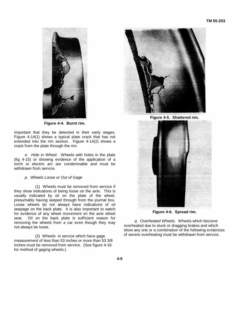
e. Burnt Rim. If a portion of the flange or rimbreaks off with a coarse fracture and rough granularsurface (fig. 4-4), the wheel was overheated inmanufacture and must be removed from service.
f. Shattered Rim. If a portion of the flange or rimparts and shows on parting a smooth surface (fig 4-5), thewheel must be removed from service.
g. Spread Rim. If the rim widens out for a shortdistance on the front face, an internal defect may bepresent, and the wheel must be withdrawn from service.This is shown in figure 4-6. Spreading of the rim isusually accompanied by a flattening of the tread, and thewheel may or may not have cracks on the tread. Thiscondition is usually associated with a shattered rim. It isusually less than 12 inches long and should not beconfused with the uniform curling over of the outer edgeof the rim around the entire wheel. This latter is acommon service condition and is not a defect Figure 4-7illustrates a subsurface defect uncovered while the wheelwas being turned to restore tread and flange contour.Unless these voids or flaky and/or laminated conditionscan be readily turned out (within the safe wear or turningmarks on the wheel), this wheel must be scrapped.
h. Shelled Tread
(1) When pieces of metal break out of thetread surface in several places more or less continuouslyaround the rim, the wheel has a shelled tread and must beremoved from service (fig 48).
(2) When excessive shelling occurs inservice, remedial measures should be taken.Contributing factors include poor track, excessive speed,excessive load, or the use of wheels of insufficienthardness.
i. Built-Up Tread. A built-up tread is caused bymetal from the tread or brakeshoe being heated to aplastic state and then dragged or built-up around the tread(fig. 4-9). Such wheels must be removed from service.
j. Grooved Tread. Wheels which havecircumferential groove or grooves in the tread to a depthof 1/8 inch or more must be removed from service (fig. 4-10).
4-3

TM 55-203
CAST STEEL WHEELS NOT HAVING FLAT BACK FACE OF RIM
ALL OTHER STEEL WHEELS
Figure 4-3. Method of measuring high flange.
k. Out of Round. Wheels which are out of round inexcess of 3/64 inch within an arc of 12 inches or less withuse of the gage as shown in figure 4-11 must be removedfrom service. This rule applies only to 33-inch wheels.
l. Cracked Hub. Hub failures take the form ofradial cracks, as illustrated in figure 4-12 which shows theback hub of the wheel. They usually occur duringmounting.
m. Thermal Cracks. Thermal cracks are caused byintensive brake heating. They occur crosswise on thetread as shown in figure 4-13 and may be confined totread or flange. In extreme cases, they may go through
the entire tread and into the plate. Thermal cracking is aserious defect and in any stage of development is causefor immediate removal of the wheel from service.
n. Cracked or Broken Plate. A wheel with acracked plate is condemnable and must be removed fromservice. Cracks in the plate develop due to stresses fromservice loads and braking. Most plate cracks areprogressive in nature. It is
4-4
TM 55-203
Figure 4-4. Burnt rim.
important that they be detected in their early stages.Figure 4-14(1) shows a typical plate crack that has notextended into the rim section. Figure 4-14(2) shows acrack from the plate through the rim.
o. Hole in Wheel. Wheels with holes in the plate(fig 4-15) or showing evidence of the application of atorch or electric arc are condemnable and must bewithdrawn from service.
p. Wheels Loose or Out of Gage
(1) Wheels must be removed from service ifthey show indications of being loose on the axle. This isusually indicated by oil on the plate of the wheel,presumably having seeped through from the journal box.Loose wheels do not always have indications of oilseepage on the back plate. It is also important to watchfor evidence of any wheel movement on the axle wheelseat. Oil on the back plate is sufficient reason forremoving the wheels from a car even though they maynot always be loose.
(2) Wheels in service which have gagemeasurement of less than 53 inches or more than 53 3/8inches must be removed from service. (See figure 4-16for method of gaging wheels.).
Figure 4-5. Shattered rim.
Figure 4-6. Spread rim.
q. Overheated Wheels. Wheels which becomeoverheated due to stuck or dragging brakes and whichshow any one or a combination of the following evidencesof severe overheating must be withdrawn from service.
4-5

TM 55-203
Figure 4-7. Subsurface defect found on turningwheel
(1) Road dirt and oil mixture on front face ofplate and underside of rim, cindered (burnt) to a hardconsistency or burnt away.
(2) A deep "blue" color on the flange, tread,or front face of rim, any or all of these conditions.
(3) A uniform pattern of "reddish brown" colorcovering back face of rim and extending down into plate.This same coloring may also be present on front face ofrim and plate.
Figure 4-8. Shelled tread.
4-6

TM 55-203
Figure 4-9. Built-up tread.
4-7

TM 55-203
Figure 4-10. Grooved tread wheel.
Figure 4-11. Gage for 3/64-inch worn-through spot in chill area. Out-of-round 33-inch wheel.
4-8

TM 55-203
Figure 4-12. Cracked hub.
4-9

TM 55-203
Figure 4-13. Thermal cracks.
Figure 4-14(1). Cracked or broken plate.
Figure 4-14(2). Crack extending through the rim.
4-10

TM 55-203
Figure 4-15. Crack originating from hole burned in wheel.
Figure 4-16. Method of gaging wheels.
4-11

TM 55-203
Section III. AXLES AND JOURNALS
4-7. Axles
a. The standards for axle design and dimensions arebased on load ratings, which in turn are fixed by journalsize. Figure 4-17 shows the limits of wear and the newdimensions for plain bearing freight-car axles, and figure
4-18 the same data for passenger-car axles. When newpassenger-car axles are used on new cars in passengercar service, the load rating of the individual axles shouldbe as shown in table 4-1. Wheels and axles areselected in accordance with the tables shown in figure 4-19.
Table 4-1. Axleload Ratings
Figure 4-17. New and limiting dimensions for plain bearing freight-car axles.
b. Common Defects. Cited below are short, generaldescriptions of various common axle and journal defectsand recommended practices.
(1) Cut or burnt journal. A depression, continue-outstreak, or an injury to the surface of the metal of wheelseats or journals, such as cut journal, must not beremoved except by a machine cut in a lathe. Such a
defeat, if allowed to remain, may cause a broken axle ora hot journal.
(2) Bent axle. All secondhand dismounted axlesshould be checked in the lathe or between centers forrotundity, concentricity, and taper of
(Figure 2A.3 PB-AAR Wheel Manual)
4-12

TM 55-203
Figure 4-13. New and limiting dimensions for plain bearing passenger-car axles.
wheel seats and journals. If an axle is found to be bent,it should be scrapped unless the journals and wheelseats can be trued up within, the specified limits. Apractice sometimes followed is to leave a chalk witnessmark around the wheel seats to show that the axle hasbeen checked in the lathe.
(3) Broken axle. Circumferential laps or seams inany portion of the axle are likely to cause trouble. Abroken axle or one with a broken end collar must bescrapped.
(4) Back journal fillet. To standardize lathe toolsand simplify shop practices, journal fillets normally areturned to the standard radii for new axles. The rules,however, permit the use of secondhand axles withminimum back fillet radius of 1/8 inch for C and largeraxles which can be gaged with the wheel-defect gage.This minimum radius should be employed only whenaxles can, be reapplied without refinishing or whenrestoring the fillets to standard radii would cause thejournal to be scrapped for a deficiency in length ordiameter.
(5) Journal length worn to limit. The length of wornjournals should be measured from a ,point 1/4 inch
above the journal surface on the face of the end collarto a point 1/8 inch below the dust-guard seat on the backfillet, as shown in figure 4-20. Any gage whichmeasures the length of journals in accordance with thismethod can be used. Figure 4-21 illustrates the type ofgage used on railroads throughout the United States.
(6) Collar worn to limit. Limits of wear will conformto those shown in figure 4-18.
(7) Journal diameter worn below limits. Limits ofwear will conform to those shown in figure 4-18.
(8) Wheel seat below limit. Limits of wear willconform to those shown in figure 4-18.
(9) Journal length worn to limit. Axles usually arescrapped because the journals have reached thecondemning length rather than because the journal orwheel seats have reached the condemning diameter. Intheaters of operations where axles may be in shortsupply, a light 1/8-inch cut off the diameter of the journalwill remove average scores or cuts in the fillets orrestore worn fillets without lengthening the journalappreciably or reducing the thickness of the end collar.
4-13
Figure 2A.2 PB-AAR Wheel Manual)

TM 55-203
Figure 4-19. Economical selection of wheels and axles.
Figure 4-20. Length of worn journal.
4-8. Journal Box and Assemblya. General. The journal box contains the bearing and
wedge assembly, the axle journal, and necessary wastepacking or lubricating pads and lubricant (fig 4-22). Thejournal -box dust guard ,and plug are inserted in avertical slot in the back end of the box. The plugprovides a close fit with the turned axle dust-guard seatto prevent cinders, dirt, or moisture from entering thebox from the back) a condition that might otherwiseincrease wear on the journal or bearing and possiblyeventually cause a hot journal. The dust guard is
inserted in place before the journal box is fitted over thejournal.
b. Bearing. The journal bearing serves the samepurpose as all other bearings. Its distinguishing featureis its unusual top bearing function in contrast to theusual lower or all-round bearing so often encountered inmachine construction. If affords a tough, solid wearingsurface at the point of contact, where the weight of thecar is transferred to the journal. Since it is necessary toreplace these bearings frequently, they are designed tobe removed easily. They are
4-14

TM 55-203
Figure 4-21. Gage to be used in measuring length of worn journals on classA to F axles, inclusive.
Figure 4-22. Typical journal box assembly.
built to meet specifications and are fabricated of eitherbronze or a .special iron. They are also provided with ababbitt metal lining, which is poured cast to face thebearing back and become an integral part of it. Thiscombination of metals has long been considered thebest for solid-bearing construction. The babbit is soft,although tough and durable, and provides a highlyefficient bearing surface. The iron or bronze backing inturn gives support and tends to dissipate the heatgenerated by transferring it to the box top.
c. Wedge. The wedge, a companion part of thebearing assembly, is provided to furnish limited rockeranchorage for the bearing It also serves to distribute theweight of the car equally over the wear surface of thebearing because of its rocker-bearing contour. The
wedge is held in place by projections provided for thispurpose in the cast-steel journal box top The lugs arereleased when the journal box is jacked up a few inches.
d. Journal Box. The journal box packing contained inthe journal box bottom is an important part of thebearing assembly Whether it consists of commercialspring-type lubricating pads or cotton and/or wool waste,when packed in the prescribed manner, it acts as a wickand feeds lubricant to the bearing. The use of wastepacking has been discontinued on most commercialrailroads in the continental United States (CONUS),present practice being to use AAR-approved lubricatorpads. There is increasing use of the roller bearingjournals for freight service also. Most Department of theArmy (DA)-owned rolling stock overseas has the waste-type journals. Details concerning proper packing ofjournal boxes are contained in paragraphs 4-12 through4-18.
e. Box Lid. The journal box lid closes the front of thejournal box and keeps out dust, dirt, and other foreignmatter detrimental to the operation of the journalbearing. Although the lid is hung so that it will remainclosed during movement of the car, it is made to openeasily for servicing and inspection. The lid is hingedfrom the top of the box and is spring-loaded to insuretight closure. An attachment is provided to keep the lidopen when servicing operations are in progress. Onoversea cars, bolt-locked journal box lids arestandardized to minimize pilferage of waste and brassjournal bearings.
f. Roller Bearings. These are being used to a greatextent worldwide for both passenger and freight cars.They require relatively little maintenance attentionbeyond periodic relubrication. Additional advantagesare almost total elimination
4-15

TM 55-203
of "hot-box" problems, better riding qualities for the car,and lessened wheel and truck wear. Roller bearings aremanufactured by various commercial concerns inCONUS of two general types-cylindrical and taperedhard steel bearings fitted snugly to the axle journal. Thetapered bearing is illustrated in figure 4-23(1). Thecomponent parts of another bearing are shown in figures4-23(2) and 4-23(3).
4-9. Causes of Hotboxes
a. Waste Grab. Threads or particles of wastebetween the bearing and the journal act as an oil wipeand cause a dry spot. Waste grab may be caused byloose threads and lint wedging (a waste grab) betweenthe bearing and journal. Loose threads must be tuckedunder, and packing must be free from lint. Wedging ismost likely when a standard size bearing is applied to aminimum size journal or one which is worn close to thelimit. Packing which is rolled up on one side of the boxis an invitation to waste grab. Rough handling in yardsor severe buffing shocks in trains may causedisplacement of the bearing on the journal for an instant,long enough for bits of waste to get under the bearing.The method of detecting waste grab is to feel along theedge of the bearing with the waste grab hook (fig 4-24).
Figure 4-23(1). Tapered roller bearing.
b. Dry or Misplaced Packing. If the packing hassettled away from the journal for any portion of its lengthor if the back roll is not in contact with the journal fillet, adry spot develops and overheating results. Theaccepted method of 'detecting misplaced packling isexamination with the standard packing iron or packinghook (fig 4-24). Dry packing is corrected by adding freeoil. However, too much oil makes the packing soggyand causes thread and lint to stick to a cold journal.
c. Loose or Overrun Lining. If the bearing lining isoverrun, it interferes with the proper oil circulation andprevents oil from following the journal into the load-bearing area. Loose or overrun lining can be detectedwith the lining or waste grab hook when checking forwaste grab.
d. Water in Packing. In freezing weather, waterfreezes in the waste threads and shuts off the capillaryaction which carries oil to the journal. It may cause thepacking to adhere to the journal and become badlymisplaced. Water also gets under the oil when it doesnot freeze and displaces oil from the back of the boxthrough the dust-guard well. Loose or poorly fitting lidsadmit snow and cause water trouble.
e. Dripping Brine. Brine dripping from refrigeratorcars causes trouble if it enters the journal box. It iscorrosive and can cause rough spots on journals.
f. Flat or Rough Wheels. Flat or rough wheels causea pounding which settles the packing away from thejournal and breaks the oil film under the bearing.
g. Overloaded Cars. Common causes of hotboxesare overloaded cars, or cars having misplaced or shiftedlading which increases the load on one or more journalboxes.
h. Defective Trucks. Trucks which are out of squareor which do not swivel freely owing to binding of sidebearings or dry center plates may contribute tooverheated bearings.
i. Axles. Bent axles may cause hotboxes. If an axleis bent between wheels, the wheel tread will showuneven wear. Bearings on bent axles will also showtapered wear, and if allowed to continue in service maybecome badly damaged by overheating. The bearingon the other end of the axle should be examined as aprecaution if a bent axle is suspected.
j. Truck Bolster Springs and Snubbing Devices.Defective or improperly applied coil springs andsnubbing devices may result in hotboxes.
4-16
TM 55-203
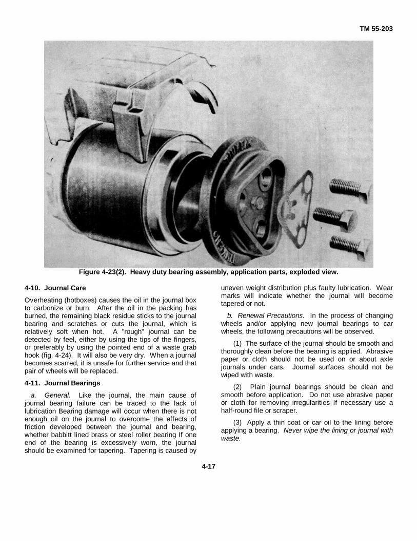
Figure 4-23(2). Heavy duty bearing assembly, application parts, exploded view.
4-10. Journal Care
Overheating (hotboxes) causes the oil in the journal boxto carbonize or burn. After the oil in the packing hasburned, the remaining black residue sticks to the journalbearing and scratches or cuts the journal, which isrelatively soft when hot. A "rough" journal can bedetected by feel, either by using the tips of the fingers,or preferably by using the pointed end of a waste grabhook (fig. 4-24). It will also be very dry. When a journalbecomes scarred, it is unsafe for further service and thatpair of wheels will be replaced.
4-11. Journal Bearings
a. General. Like the journal, the main cause ofjournal bearing failure can be traced to the lack oflubrication Bearing damage will occur when there is notenough oil on the journal to overcome the effects offriction developed between the journal and bearing,whether babbitt lined brass or steel roller bearing If oneend of the bearing is excessively worn, the journalshould be examined for tapering. Tapering is caused by
uneven weight distribution plus faulty lubrication. Wearmarks will indicate whether the journal will becometapered or not.
b. Renewal Precautions. In the process of changingwheels and/or applying new journal bearings to carwheels, the following precautions will be observed.
(1) The surface of the journal should be smooth andthoroughly clean before the bearing is applied. Abrasivepaper or cloth should not be used on or about axlejournals under cars. Journal surfaces should not bewiped with waste.
(2) Plain journal bearings should be clean andsmooth before application. Do not use abrasive paperor cloth for removing irregularities If necessary use ahalf-round file or scraper.
(3) Apply a thin coat or car oil to the lining beforeapplying a bearing. Never wipe the lining or journal withwaste.
4-17

TM 55-203
Nomenclature
Figure 4-23(3). Nomenclature, heavy-duty bearing assembly.
(4) Renew journal bearings when:
(a) Back lug is broken or cracked.
(b) Worn 1/4 inch or more lengthwise at eitherend.
(c) Combined wear lengthwise is 3/8 inch ormore.
(d) Lug worn to a depth 1/8 inch or more in areawhich is over 50 percent of contact face.
(e) Combined wear, on both sides of lugextension is 1/4 inch or more at any location.
(f) Lining is worn through to brass at any location3/8 inch or more above the lower edge of brass side
walls.
(g) Lining is loose or broken out.
(h) Lining is pulled in journal contact area(indicated by wear pattern).
(i) Wheels and axles are changed (2 bearings foreach set of wheels).
(j) Missing.
c. Method of Removal. To remove a journal bearingthe journal packing should first be removed
4-18

TM 55-203
Figure 4-24. Packing iron and waste grab hook.
moved from the journal box. Suitable size journal jacksshould be placed under both journal boxes The one atthe opposite end from which the bearing is to beremoved will merely be raised to contact the bottom ofthe journal box to counterbalance and minimize thejacking action In the other end. If only one jack isavailable, the wheel may be blocked by suitable sizeblocks placed between wheel tread and car frame. Jackunder journal box from which the bearing is to beremoved will be raised until the wedge over the bearingwill slide free. The wedge and then the bearing will becarefully removed by using packing hooks. Carrepairmen or inspectors will not insert their fingers orhands between the wedge, journal, or journal box top.Reverse procedure will be used for placing new bearing.It will be placed part way in the box by hand, pushedover the journal collar into place with a packing hook,wedge inserted in the same manner, jacks lowered and
removed, and journal box packing replaced.
d. Handling. Journal bearings, whether new, relined,or broached, should be handled with the same care andattention as finished machine parts. The lining isrelatively soft and easily damaged by abrasion orimpact. Railway car repairmen and supply personnelhandling the journal bearings will be guided by thefollowing general policies.
(1) Bearings with loose, thin, or spread lining, butwithin dimensional limits of standard specifications, maybe reclaimed by relining.
(2) If journal bearings removed in wheel changes ortaken from dismantled cars are within dimensionallimits, they may be reclaimed by boring or broaching,provided that not less than 1/8
4-19
TM 55-203
inch of lining metal remains. Such bearings should betested for loose lining after broaching. This is done bystanding the bearing on end and tapping it with ahammer If the lining is tight, the bearing will have aclear, metallic ring Journal bearings should be selectedfor broaching by proper inspecting and by use ofappropriate gages.
(3) Bearings with lining melted off from overheatingin service should not be relined.
(4) When wheels are removed to be turned andwhen it is feasible to do so, it is good practice to returnbearings to service with the same journals, providedthey are within dimensional limits and linings are tight.
(5) Bearings should not be thrown or dropped orallowed to lie around mixed with other material.
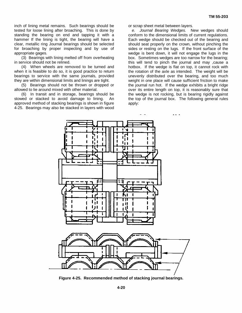
(6) In transit and in storage, bearings should bestowed or stacked to avoid damage to lining. Anapproved method of stacking bearings is shown in figure4-25. Bearings may also be stacked in layers with wood
or scrap sheet metal between layers.e. Journal Bearing Wedges. New wedges should
conform to the dimensional limits of current regulations.Each wedge should be checked out of the bearing andshould seat properly on the crown, without pinching thesides or resting on the lugs. If the front surface of thewedge is bent down, it will not engage the lugs in thebox. Sometimes wedges are too narrow for the bearing;this will tend to pinch the journal and may ,cause ahotbox. If the wedge is flat on top, it cannot rock withthe rotation of the axle as intended. The weight will beunevenly distributed over the bearing, and too muchweight in one place will cause sufficient friction to makethe journal run hot. If the wedge exhibits a bright ridgeover its entire length on top, it is reasonably sure thatthe wedge is not rocking, but is bearing rigidly againstthe top of the journal box. The following general rulesapply:
Figure 4-25. Recommended method of stacking journal bearings.
4-20
TM 55-203
(1) Wedges cracked, distorted, or broken shouldnot be reapplied.
(2) Wedges flat on top for a length exceeding theoriginal diameter of the journal should not be reapplied.Wear limits are indicated in the following table.
Table 4-2. Journal Wear LimitsNormal journal size (in.) Wear limit flat-
lengthwise (in.)
4 1/4 x 8 ......................................... 3 1/45 x 9 ............................................... 45 1/2 x 10 ....................................... 4 1/26 x 1 ............................................... 56 1/2 x 12 ....................................... 65 1/2
(3) Wedges having the overall length reduced morethan three-sixteenths of an inch at contact surfacesshould not be reapplied.
(4) If bottom of bearing surface of wedge is unevento the extent of 1/64 of an inch, as determined by astraightedge or suitable gage, wedge must be removedfrom service.
f. Dust Guards. Whenever wheels are changed, thedust guards also should be renewed.
Section IV. JOURNAL BOX LUBRICATION
4-12. Journal Packing
a. General. Lubrication failures which result inoverheated journal bearings (hotboxes) cause seriousdelay in railway operations. Trains are delayed becauseof the necessity of attending to, or setting out cars withhotboxes. This results in delays and interference withother train movements. Hotboxes not detected in timemay result in journals burning off and consequentderailments. Car journals may be packed with oil-soaked waste (fig 4-26) or AAR-approved mechanicallubricating devices (fig 4-27). These devices consist ofoil-soaked pads held against car journals be retainersprings. AAR Interchange Rules, applicable In CONUS,state that "-journal lubricating devices, AAR-approvedtypes, conditionally approved types, or types authorizedfor limited test application are required on all carshaving plain bearings in interchange."
b. Packing Adjustment. Journal packing may appearin good condition on first examination; however, carinspectors should make a thorough Inspection by use ofthe packing hook (para 4-9a). The packing hook shouldbe pushed under lone side of the Journal as far as it willgo, and out-of-place packing turned and adjusted toprovide a new bearing surface. When packing is left toolong without this adjustment, the part that bears on thejournal becomes glazed as the turning journal pressesagainst it. Dust and dirt tend to accumulate at this pointand contribute to journal wear. These conditions reduceor stop the oil flow to the journal and may cause it tobecome overheated, i.e., a hotbox.
4-13. Inspection of Journal Packing
a. General. When inspection reveals any of thefollowing conditions, action will be taken as indicatedbelow.
(1) If the journal packing is dirty or mixed withgrease, the box should be repacked.
(2) Journal boxes containing excessive amounts -ofsnow, ice, or water should be repacked. Particularattention should be given to all boxes located underdrains of ice bunkers or refrigerator cars. When foundto contain drippings, the boxes should be repacked.
(3) Journal boxes that have been in high watershould be cleaned and repacked as soon as practicable;careful examination must be made.
for corroded or pitted journals.
b. Reoiling. If packing shows dry along the -top afterhaving been reset or if there is less than 1/2 inch of oilin the bottom of box, oil should ,be added, starting at theback of the box and working the oil can spout forwardalong both sides of the journal. If the direction of carmovement is known, oil should be added on the risingside of the journal only. The box lid must closeproperly, and there must be no loose threads of packinghanging outside. If it is necessary In cold weather toadd cutback or thinner oil, hot car oil or thin oil having aflashpoint of 300° F. or above may be used The use ofkerosene oil or any oil with a flashpoint below 300° F. isprohibited.
4-14. Preparation and Handling of Packing Materials
a. Packing must consist of all new, all renovated, or ablended mixture of new and renovated waste orlubricating pads as determined by the requirements ofthe service for which it is to be used.
b. The waste should be loosened and shaken outthoroughly and then placed in a saturating vat. Thewaste should be completely submerged 'in oil(temperature of the oil not less than 70° F.) for a periodof not less than 48 hours to insure
4-21

TM 55-203
Figure 4-26. Method of packing journal boxes.
4-22

TM 55-203
Figure 4-27. Typical lubricator pad.
thorough saturation of the threads. To remove theexcess oil, it should be drained on a rack until thepacking is resilient or elastic. Oil should not drip fromdrained packing when lifted from the drain rack, but oilshould flow from drained packing squeezed in the hand.
c. When prepared packing is shipped, drums orcontainers capable of excluding water, dust, and foreignmatter should be used. When such containers are usedfor return shipments of old packing, they should bethoroughly cleaned before being refilled.
d. Prepared packing stored in shipping containersawaiting use should be protected with tight-fitting lids toprevent contamination.
e. Prepared packing in tanks, vats, or othercontainers should be turned over or the accumulated oilin the bottom drawn off and poured over the top at leastonce in each 4 hours during working hours.
4-15. Preparation for Packing Journal Boxes
a. Before packing a journal box, the interior, includingthe journal, bearing, and wedge, must be thoroughlycleaned. The front of the box, which may come incontact with the packing being applied, and the inside ofthe lid must also be cleaned.
b. When applying new boxes or reapplying boxes, thedust-guard well should also be cleaned as above.
c. Boxes should be inspected for cracks which mightcause oil leakage.
d. Journal box rear seals or close-fitting dust guards,dust-guard plugs, and box lids complying withspecifications should be applied.
4-16. Packing Journal Boxes (Waste)
a. All reclaimable packing removed from journalboxes should be pulled directly into containers, avoidingcontact with the ground or any other place where it maypick up dirt. Large, loose pieces of lining, grease, orforeign matter should be removed. The packing shouldthen be taken promptly to the waste plant or the centralshipping point. It should be kept under cover to protectit from weather, dust, or dirt, and to exclude water.Removed packing must not be reused until it has beenrenovated. When reclaimed packing is insufficient forrequirements, new waste should be added andthoroughly blended to form a uniform mixture.
b. Back rolls consisting of light-twisted preparedpacking with ends turned under, or of suitable size to fillthe space between the journal and the journal box,should be inserted and worked back under the journal tothe extreme back of the box as shown in the top row offigure 4-26. The length of the roll should suit thediameter of the journal, and the ends must beapproximately 1 Inch below the centerline of the journal.The roll must be well up against the journal so as toproperly lubricate the journal fillet and to keep out dustand dirt Rolls tied with twine should not be used.
c. Sufficient packing is applied in one piece (B, fig 4-26) or in rolls (A, fig 4-26) to firmly fill the space underthe journal and to bear evenly along the length of thejournal to prevent settling away. Care must be taken tohave the 'packing bear evenly along the full length ofthe lower side of the journal. Boxes equipped with aspring-type packing retainer device must have packingat front, finished off, straight down from the inside faceof the journal collar (C, fig 4-26) Boxes not equippedwith a packing retainer device must have packing at thefront finished off on a downward Incline (C-I, fig 4- 26).
d. For the one-piece or bulk method, after the backroll has been applied, with the packing bucket directlyunder the box, the packing is placed across the fullwidth of the mouth of the journal box and the strandsallowed to hang outside. More packing must always beadded before the hanging strands are placed inside thebox This has the effect of binding all of the body of thepacking together The top of the packing along the sidesmust be approximately 1 inch below the centerline of thejournal.
4-23
TM 55-203
e. For the roll method, lightly twisted rolls of preparedpacking with the ends turned under, or suitable size tofill the space between journal and journal box, are usedto fill up the box as shown in the bottom row of figure 4-26. The back roll (1) and the additional rolls marked (2),(3), and (4) are prepared and inserted In the samemanner from the back roll to the inner or back face ofthe journal collar. No loose ends of threads shouldprotrude at sides or ends, and any loose ends or threadsshould be carefully tucked under the sides of thepacking. The number of rolls per box is optional. Whenthe box has been serviced the level of packing on eachside should be approximately 1 inch below thecenterline of the journal. Packing should be added orremoved if necessary to produce this condition.
f. Oil should be added to such boxes as do notappear to contain sufficient oil after packing. Thereshould be approximately 1 inch of oil in the bottom ofthe box in front of the journal collar. Too much oilcauses soggy packing and results in oil being thrown outof back of the box. Lubrication is adequate if oil showsbetween the fingers when a handful of waste issqueezed.
g. Journal boxes equipped with approved spring-typepacking retainer devices should be packed more firmlythan those without such devices to insure that bothpacking and retainer will stay in proper position.
4-17. Packing Journal Boxes (Lubricator Pads)
a. General. All oil waste packing or damaged or wornlubricator devices will be removed from the journal box.Journal bearings and journal box will be cleaned andinspected as prescribed in paragraph 4-15. Applyjournal lubricator in accordance with manufacturer'sinstructions provided in each lubricator shippingcontainer. Rail- way car oil (VV-L822) will be used tosaturate the pad and for subsequent replenishing.When necessary to replace all lubricating devices in acar at the same time, all devices applied must be of thesame kind. Refer to the current issue of the AARInterchange Rules for complete listing of AAR"approved," "conditionally approved," and "approved fortest."
b. Typical Pads. Figure 4-27 depicts a typicallubricating pad, constructed of chenilled cotton fabric.Lubrication is provided by wicking action. It has onecontinuous pull strap extending out at each end fittedwith brass grommets for ease of adjustment andremoval from box. Only those types of lubricating padswhich have been conditionally approved, finallyapproved, or approved by the AAR for limited testperiods are authorized for installation in any car journalwhich is in interchange service. DA policy is to convertall car journal box packing to the lubricator pad type onmilitary-owned cars, even though the cars are used
interpost or interplant only, and are not offered to anycommercial railroad in interchange. Initial application ofthese lubricating pads is to be made in accordance withinstructions of the manufacturer.
c. Inspection. Inspection of journal boxes equippedwith lubricating devices consists of visual examination tosee that the lubricator, journal bearing, and wedge are ingood condition and in their proper places and that thebox is not overheating. No servicing or setting up with apacking iron is required unless the lubricator is shifted inthe box, in which case it should be adjusted to theproper position. Journal box packing (waste) will not beused with these devices.
d. Cause for Renewal. Journal lubricating deviceswill be considered as defective and requiring renewalwhen:
(1) There is any noncontact with journal.
(2) There is any scorched or burnt area.
(3) There is any glazing of the surface whichcontacts the journal.
(4) Top, front, back, or side is torn for more than1/2 its length.
(5) Fabric is deteriorated or decayed.
(6) Exposed core or metal part is contacting journal.
(7) Missing.
(8) Removed on account of change of wheels andaxle.
(9) Journal box repairs require removal oflubricators.
(10) Journal boxes receive periodic lubricationattention (para 4-19).
(11) AAR approval has been withdrawn (para 419).
(12) When involved with a hotbox requiring renewalof journal bearing.
4-18. Periodic Attention-Plain Bearing JournalBoxes
a. Overdated when Equipped with AAR Approved,Conditionally Approved or Approved for TestLubricators.
(1) Stenciled with numeral "30" adjacent to repackstenciling information.
(a) After expiration for 30 months.
(b) After expiration of 29 months when car is onrepair track.
4-24
TM 55-203
(c) Between 24 and 29 months when car has achange of wheels or truck repairs requiring removal oflubricators in one-half of the boxes on car.
(2) Not stenciled with numeral "30."
(a) After expiration of 24 months.
(b) After expiration of 13 months when car is onthe repair track.
(c) Between 18 and 23 months when car has achange of wheels or truck repairs requiring removal oflubricators in one-half of the boxes on car.
Note. Cars under authorized test for repack periodmust be repacked at expiration of such period and all teststenciling removed. However, where conditions In (c)above prevail, they will have priority over test period.Expiration of time limits is defined as after the date ofmonth stenciled on car.
b. Attention at Any Time.
(1) When stenciled for type of lubricators that arenot approved, conditionally approved, or approved fortest per AAR Interchange Rules, regardless of type oflubricators in boxes.
(2) When equipped with waste packing.
(3) When stenciling is missing, incorrect, orindistinct.
(4) When not stenciled for any kind (name) oflubricating device.
(5) When boxes have been submerged.
(6) When car is on repair track and all lubricatorsare defective (para 4-17d).
c. Correct Repairs.
(1) Remove journal bearings, wedges, andlubricators or waste packing Thoroughly clean boxes,including inside of lid and front of box that could come incontact with lubricator when being applied Do not usewaste for cleaning purposes.
(2) Examine journal bearings, wedges, journal stopsand box lid seals, renew if defective.
(3) Renew dust guard plugs when missing ordefective and apply sealer material on top of plug.
(4) Secure wooden dust guard plugs (when used)with a device to lock the plug In place.
(5) Renew defective rear seals only when truck isdismantled for any reason.
(6) Apply new lubricators only, in accordance withmanufacturer's instructions furnished in each lubricatorshipping container. Prior to installation saturate thelubricator in railway car oil If any free oil is visible inbottom of box after lubricator has settled, no furtheroiling is necessary. If there is no indication of free oil,add oil until approximately 3/8 inch of oil is visible inbottom of box.
(7) Scrape off old stencil and paint over with quick-drying black paint.
(8) Apply stencil (similar to that shown in figure 8-19 for airbrake testing) as follows:
(a) Show place, month, day, and year ofrepacking.
(b) Show railroad, military, or private linereporting marks.
(c) Show symbol for repack "RPKD."
(d) Use same shop or station initial as used forairbrake stencil (fig. 8-19).
(e) Show name of lubricator applied.
(f) Stencil numeral "30" adjacent to repackstenciling data when car is equipped with sealed andstabilized journal box assemblies.
(g) Stenciling must be on car body, near bodybolster at diagonal corners, with not less than 1-inchfigures and letters.
Section V. TRUCK SIDE FRAME, BOLSTER, AND SPRINGS4-19. Truck Side Frame
a. General. The truck side frame is the trussed cast-steel frame of the truck assembly on the outside of thetruck wheels, which extends from one axle to the other(fig 4-28). The journal boxes, except for lids, the brake-rig lugs for hanger-type brake beams, and the guideslots for hanger-less-type brake beams are cast integralwith the side frame proper. These journal boxes aredesigned to seat the top bearing wedge and bearingassembly, provide a rear slot for the dust guard andplug, and retain lubricating pads and lubricant for journaland bearings. When the roadbed is not in goodcondition, especially around curves, the truck side
frames will be subject to heavy impact forces. Uneventrack and excessive swaying of a car body are thegreatest contributing causes to increased wear on sideframes. Figure 4-29 shows the disassembled truck withcomponent .parts.
b. Repairs. The truck side frame is subjected tosevere stresses and strains under a car, particularlywhen under load and traveling at high speed. Sideframes will wear in the center portion where the springsand truck bolster are located. Cracks also may be foundin this area or anywhere on the side frame. Journalboxes may contain broken or worn lugs. A defectiveside frame
4-25

TM 55-203
Figure 4-28. Typical truck, assembled.
usually is removed and a new or reconditioned oneinstalled. When it is necessary to build up a !surface bywelding, it should be done evenly to produce the desiredfinish without excessive grinding. Building up ofsurfaces and the welding of cracks or fractures at anylocation are permissible on CONUS-type equipmentprovided the side frame is of U-section design,manufactured subsequent to 1926. In CONUS, AARCode of Rules governs these repairs Frames must beremoved from the truck, and the section to be weldedmust be preheated locally to approximately 6000 F.before welding is started. Frames must be normalizedafter welding has been completed and legibly markedwith place and date (AAR regulations in CONUS). Oncertain limited sections of the Journal box and brakehanger bracket, heat treatment is not required.
4-20. Truck Bolster
a. General. The truck bolster (fig 4-28) is the bodybearing part of the truck. It is designed to support the
car's underframe and load. It is set crosswise and thematching car body bolster rests on it, secured by theweight of the car and the matching of the male andfemale forged or cast-steel center plates. A loosecenter pin in the center plates helps resist lateralmovement. Under normal conditions, the truck bolsteroscillates in its position between the columns of the sideframe. On application of the brakes, if severe, thebolster will tilt, and the corners of the bolster will rubagainst the faces of the truck columns (side frames).With its fitted ends working in and guided by the castcolumns of the cast-steel truck side frames, the truckbolster transmits its load to the bottom spring clusters(leaf springs in passenger cars) which have caps andbearing plates. The frame load is in turn transferred tothe axle journals and wheels and then to the railsthrough journal bearing assemblies (brass and wedge)or roller bearings located in the journal boxes of the sideframes.
4-26

TM 55-203
Figure 4-29. Typical truck, disassembled.
b. Bolster Repairs(1) Bolsters wear at the center plate, at the side
bearings, and at the ends where contact is made withthe columns of the side frames as discussed in a,above. It is generally feasible to build up worn spots on
cast-steel bolsters by welding if AAR (CONUS) and TRS(overseas) regulations permit. A bolster worn beyondreclaimable limits must be removed, scrapped, and anew one installed. There are no restrictions on weldingof pressed or structural steel bolsters.
4-27

TM 55-203
(2) To remove a truck bolster of the integral castframe type illustrated in figure 4-28, the followingprocedures will apply:
(a) Remove all packing (or lubricants) fromjournal boxes.
(b) Disconnect top brake rod from truck live lever.
(c) Jack end of car to a height sufficient to allowtruck to be rolled from under the car.
(d) Place safety trestles under corners of car sothat if the jacks fail, the car will not fall.
(e) Remove center pin. If it is necessary to rolltruck from under car before placing safety trestles, apair of long-handled tongs-never bare hands-will beused to remove the center pin.
(f) Roll truck from under the car.
(g) Remove all brake rigging, including brakebeams, rods, levers, and safety hangers.
(h) By means of jacks or hoists, raise bolstersufficiently to permit removal to journal box wedges.
(i) Remove spring plank if used.
(j) Lower bolster to a position, which will allow theside frames to be slipped from ends of bolster
(k) Using hoists or wheel sticks, swing sideframes clear of bolster.
(l) Remove bolster.
(3) To reassemble the truck, lower the bolster intoplace, roll up the wheel sets, put the side frames intoposition, and assemble the remainder of the parts in thereverse order of the disassembly, described above.Bolster side control wedges (if used) should belubricated after assembly.
c. Welding Bolsters. Inspection of bolsters removedfrom car trucks may reveal loose rivets in the male andfemale center castings and cracks 'in the body of thebolster. There are no restrictions on the welding ofcracks or fractures in bolsters, but cast-steel bolstersmust be removed from the car before welding andnormalized after welding. Pressed or structural steelbolsters should be removed from the car truck if majorcracks or fractures are detected. Loose rivets in thecenter plate will be cut out and replaced.
d. Center Plate The truck bolster center plate (fig. 4-28) is a depression into which the center casting rivetedto the center sill of the car fits. It is held in place by theweight of the car body, the conformation of the casting,and a center pin. The center plate should be inspected
for the presence of dirt, grit, scale, or any foreign matterwhich will cause binding and above average wear. Thecenter plate and pin should be lubricated with suitablehard grease prior to being replaced under the car. Thecenter plate should be examined for cracks and brokenportions. If damage is noted, the center plate andbolster, if necessary, should be removed as outlined inb, above, and replaced with a new one. If the centerplate is riveted on, it can be replaced singly. Liners orshims placed in center plates to adjust coupler height(para 4-2) are permissible, providing the vertical bearingsurface of the center plate is not reduced below 1 1/8inches. Such liners shall be of one piece not to exceed1/4 inch thickness. To inspect center plates for cleaningand lubrication, the car can be raised by hoists or jacksto a sufficient height to make the center plate visible forinspection. Care should be taken not to put the hands orfingers into the center casting under suchcircumstances.
e. Side Bearings. Side bearings, consisting of specialsteel plates with flat bearing surfaces which contactsimilar plates on the body bolster, are fabricated as apart of the bolsters. They are designed to steady the carbody and prevent excessive rocking by maintainingintermittent contact with similar members of the bodybolster. Instead of a flat bearing surface, a combinationof rollers and rockers may be found on some cars. Newcars specifications require side-bearing clearances to beadjusted within the limits of 1/8 inch to 1/4 inch perbearing, measured at each bearing, with the car on leveltrack and the car body level. Total side-bearingclearance at B-end and R and A-end L and A-end and Rcorners must be the same as the total clearance at B-end L and A-end R corners, with a permissible variationof 1/8 inch. By raising the end of the car above thetrucks, the side bearings can be inspected for wear orbreakage. If repairs or replacement are indicated, thetruck should be rolled out from under the car to facilitatethe repair. If replacement is necessary, the old sidebearing can be burned off and a new one affixed byriveting or welding in its original manner. Care will betaken to adjust for proper clearances.
4-21. Truck Springs
a. General. The truck bolster ends, properly fittedbetween the columns of the truck side frame, will rest -on unit clusters of coil springs (fig. 4-28) which, in turn,are set into built-up shouldered spring pockets of thetruck side frame and truck bolster. The makeup of thespring clusters is dependent upon the loads and springtravel dictated by operating conditions.
4-28

TM 55-203
These clusters, with cap and seat plates, are removable,since they are fixed to neither the bolster nor the sideframe.
b. Spring Replacement. Bolster coil springs (fig 4-28) may break and become lost. When this occurs toone spring, it is not too serious. However, additionalstrain is thereby placed on remaining springs and Incase of a heavily loaded car they may be unable tocarry the load, thus possibly resulting in truck failure, hotjournal, derailment, or other serious damage. Rusting orbreakage of connecting parts may cause a spring to
become loose and eventually lost. If the spring plank isdamaged, great pressure will be applied to the springs,resulting in broken springs or the tilting of the truck.When a spring is found broken or missing, a new springwill be installed. To do this, the truck can be partiallydisassembled following the procedure outlined above.The weight must be taken from the bolster and bolster'raised high enough for the spring to come free. Newsprings should fit the spring seats exactly and have thesame snubbing characteristics as the other springs inthe group.
4-29

TM 55-203
CHAPTER 5
UNDERFRAME ASSEMBLY
Section I. GENERAL
5-1. Underframe Sills
a. Center Sill. The center sill of a structural frame isthe built-up central, longitudinal structural member ofthe underframe of a car and forms the backbone of theunderframe. It transmits the buffing shocks from oneend to the other. It contains the couplers and draftgears in pockets at either end.
b. Side Sill. The underframe side sill is the outsidelongitudinal member of the underframe. In some cars,especially flatcars, the side sills are strengthened. Inother cars, such as gondolas and copper cars forexample, the entire side of the car may be designed asa deep plate girder or truss to carry much of the load tothe bolster. On hook-and-link equipped cars, it isreinforced to withstand buffer shocks.
c. End Sill. The end sill of an underframe is thetranverse member extending across the ends of thelongitudinal center and side sills. This member may befabricated of rolled or pressed steel, with sill connectionsof either a bracket or gusset-plate type.
d. Floor Stringer. In steel car construction, the termfloor stringer is applied to the longitudinal memberssometimes used to support floors. Longitudinal floorstringers sometimes occupy positions similar tointermediate sills, but are not designed to act as sills.
5-2. Underframe Body Bolster
The body bolster is the transverse member of the
underframe over the car trucks through which the weightof the underframe, super-structure (if any), and thelading of the car carried by the longitudinal sills istransmitted to the truck. The body bolster carries andtransmits its load through the mated body bolster andtruck bolster center plates, the body bolster resting onthe truck bolster. A typical welded-steel underframe isshown in figure 5-1
5-3. Crossbearers and Crossties
Crossbearers are transverse structural members of theunderframe placed between the bolsters. They act as atie between the body side sills and the center sillanchorage and help to distribute the weight of the carand lading and to stiffen the structure. Crossbearersbuilt as single units extend across the car from side sillto side sill, usually with a filler between the center sills.The term crosstie is commonly applied only to thosemembers which tie together the side sill with the near-side members of the center sill.
5-4. Striking Plates or Castings
The striking plates or castings are a component part ofthe coupler and draft gear arrangement. They areriveted or welded to the end sills and fitted around theopening for freight car couplers. They help preventdamage to the center sill, as the coupler horn will strikewhen the draft gear is weak or defective.
5-1

TM 55-203
Figure 5-1. Typical welded-steel underframe.
Section II. UNDERFRAMES FOR CARS USED IN THEATERS OFOPERATION
5-5. General
One of the basic developmental requirements of theoversea fleet was a flatcar underframe upon whichsatisfactory superstructures for boxcars, high-side andlow-side gondolas, and possibly caboose cars could beeasily and economically assembled in the field and thenused in service with a minimum of maintenance. The40-ton oversea flatcar with its underframe truss-rodfeatures is built to take the standard automatic coupler
at a 34 1/2-inch coupler height as well as the Europeanhook-and-link coupler or the Willison coupler at a 41-inch coupler height. The change in ,coupler height isaccomplished by the use of collars between bolstercenter plates and shims at the side bearings of both thebody and truck bolsters. Design load limits are fixed at34,000 pounds per axle based on use of 5- by 9-inchaxles.
5-2

TM 55-203
5-6. Field Assembly and Maintenance
Underframes of the knocked-down oversea fleet arecompletely fabricated at the car builder's shops inCONUS. They are shipped to depots for storage and/ortransshipment overseas. Field assembly of flatcars willinvolve placing the underframe on truck assemblies,inserting the klngplns and keys, and mounting the brakecylinders
and foundation brake gear, including the necessaryconnection with that part of the foundation brake gearbuilt into the truck assemblies. Oversea underframemaintenance will probably consist almost entirely ofstructural repairs, which are discussed in the followingsection. Figures 52 and 5-3 illustrate two steps in theassembly of knocked-down type cars.
Figure 5-2. Component parts being installed on underframe.
5-3

TM 55-203
Figure 5-3. Lowering completed underframe on trucks.
Section III. REPAIR PROCEDURES
5-7. General
The usual procedures to be used in making typical repairsto car underframes and/or their components arediscussed In the following paragraphs; only generalinformation is included. The nature and extent of thedamage, the accessibility of the damaged parts,preliminary disassembly or removal of components, andother factors determine the individual steps required forany particular repair job. Details are not discussed, butthe general procedures to be followed in repairing certaindamaged parts or frame members are Indicated. Exactmethods are based on the good judgment and experienceof the carman.
5-8. Special Jobs
a. Use of Templates. Special kinds of repairs mayrequire a special pattern of patch. After the method ofrepair has been determined, a template of the patchshould be made. When a part is to be replaced by a newone, a template insures that the new part will fit exactlyand that any necessary holes or cuts will be marked outcorrectly with a minimum of lifting and figuring.Templates of skeleton construction, braced to retainshape, are the easiest to make and to handle. A templateshould be of light construction for
ease of handling. After careful measuring and planning,the required template is constructed. The template is usedto mark for cutting the desired piece from a steel plate,beam, channel angle iron, or the kind of materialnecessary for the repair. The template is also used formarking the new piece The piece is placed on firm, heavyplanks supported with benches, horses, or some heavybase, as illustrated in figure 5-4. The template is clampedIn position on the piece, and holes and cuts are marked.After the template is secured, the piece is ready forcutting and drilling, followed by installation on theunderframe or other part of the car Figures 5-5 and 5-6show templates for angles and I-beam, respectively.When it is necessary to make several duplicate parts,stops on the templates (fig 5-5) save time and trouble.
b. Straightening Out-of-Square Underframes. Whena car is sideswiped or receives a blow on a corner, thewhole underframe may be forced out of square. The endand side sills may be bent so badly that they must beremoved. They are later heated and straightened underthe press. The -center sill, body bolsters, crossties,diagonal braces and the remainder of the underframe canbe left connected. Two chains are attached, one aroundthe end of each body bolster, and brought
5-4

TM 55-203
together In the middle of the frame with a pull jack. Thepull jack exerts a diagonal pull on the underframe,bringing it back into square. Application of heat 'to thecenter sill may speed the operation.
5-9. Steel Splicesa. General. Frequently, underframe sills are cracked
or broken through deterioration, rough handling, oraccident. In many cases the crack or break is of suchproportion or in such a location that the whole membermust be replaced. In other cases the sill may be repairedby "splicing." Where practicable and especially in atheater of operations, splicing of sills is recommended.Splicing may be done on a sill adjacent to another spliceor adjacent to a sill that is spliced Whether the break is onthe inside, outside, or completely through, the procedureswill be generally as explained in b, below. In all cases ofsplicing, reinforcing cover plates must be used on eachside of the broken sill, over the fracture.
b. Center Sills. Before a broken sill is spliced,measure the web and flanges A piece of steel plate asthick as the sill to be spliced will be used in marking offand cutting out the splice The location of rivet holes arethen marked off on the sill to be spliced Marking off maybe done by using a template as described in paragraph 5-8a or by measuring and marking. After the splice plate isput in place, the holes to be made are (marked forpunching or1 drilling Before any holes are made in the sill,the adjacent broken parts of the sill must be drawntogether by bolts for butt-joint splicing These tie bolts holdthe sill until the splice is secured. In CONUS, AARregulations may require welding of the break beforeapplication of the splice cover plates As soon as the sill isprepared, the cover plates are applied and riveted. Theriveting process is discussed in paragraph 5-19.
c. End and Side Sills. Because of the stresses landstrains to which the end sills are subjected, they arefrequently badly bent between the buffer and the corner ofthe car. This damage may be repaired by placing a jackagainst the bent part any applying heat to the sill with anacetylene torch, at the same time tightening on the jackas illustrated in figure 5-7. This usually will restore an endsill to its original position. Side sills usually can bestraightened in a similar manner.Small kinks in side and end sills may be straightened byheating and hammering Broken side sills may be splicedat any point between the end sills.
d. Crossbearers Defective Crossbearers usually arecut out and replaced with new ones, since they connect tothe center and side sills. While it is a simple operation toremove them, crossbearers may be patched if it can bedone satisfactorily. Whether replaced or repaired, thecrossbearer must be removed by cutting the rivets
5-5
Figure 5-4. Marking with templates.
Figure 5-5. Template for angle.
Figure 5-6. Templates for I-beam

TM 55-203
Figure 5-7 Straightening a pushed-in end sill byjacking against the body bolster.
which connect each crossbearer to the center sill and sidesills (fig 5-1). If the angle irons, which connect the twoarms, are good they can be cut loose and used on thenew crossbearer. In theaters of operations whereacetylene is not available, rivets can be removedmanually by cutting the heads off with a chisel bar andsledge hammer, and knocking the old rivet body out byuse of a drift punch and hammer.
e. Stringer Supports. Defective stringer supportsusually are replaced They are removed in a mannersimilar to that described for renewing crossbearers.
5-10. Draft Castings
Draft castings are frequently found broken or missing.Broken draft castings can be removed by taking out thedraft gear, the coupler, and uncoupling level. The rivetswhich hold the draft casting in place can be removed byusing acetylene torch equipped with a rivet-piercing tip. Ifa rivet buster is available, the punch can be substitutedfor the chisel and the old rivets backed out. When therivets are removed, the draft casting can be easilylowered out. The new draft casting can then be riveted(or welded) in place.
5-11. Cover Plates
The center sill cover plate may be patched by cutting outdefective parts and replacing them with new ones. Thenew plate should be of the same thickness as the oldcover plate and should be lapped about 6 inches at thepoint of the old cover plate. Defective body bolster coverplates should be removed, since they bear too, muchstrain to make a patch practical.
5-12. Body Bolster Fillers
a. General. Body bolster fillers are frequentlybroken. Substantial repairs can be made with a patchflanged on top and bottom to fit the place to be patched orspliced. Such patches should extend at least 12 incheson each side of the break. They should be secured byrivets through the web on each side, staggered to fit thecondition. In CONUS, where AAR rules permit, thepatches can be welded When riveted, rivets securing thetop and bottom flanges of the patch to the flanges of thebolster should be long enough to go through the top andbottom cover plates. Usually, however, it is best to cutout broken body bolster fillers and replace them. Toremove a pressed-steel flanged filler, the top and bottomcover plate must be cut loose and the rivets whichconnect the filler with the center sill and side sills must becut The rivets which connect the adjacent crossbearer tothe side sill must also be cut The side sill can then besprung out far enough to allow the old filler to be removedand the new one fitted into place.
b. Body Bolster Center Plate. Broken body bolstercenter plates must be renewed. The rivet heads are cutoff with an acetylene torch or a rivet buster and the oldrivets punched out. Sometimes the center plate will haveto be pried down after the rivet heads are removedbecause the plate shanks are bent sideways to fit thesmall space between the lower bolster cover plate and thecenter plate In this case, the rivet shank cannot be drivenup and it will be necessary to burn off the rivet shankbelow the center plate before the upper rivet head can beremoved. During riveting (or welding), the new plate canbe held temporarily in place by two diagonally placedbolts.
5-13. Straightening and Repairing Sills
a. General. If a center or side sill is so badly brokenor damaged that repair is impractical, the sill must be cutout completely, removed and replaced with a new one. Itmust be disconnected from the end sills, the bodybolsters, the diagonal braces, the crossbearers, and thestringer supports. When the new sill is installed, it mustbe connected to all these same parts.
b. Broken End Sills. When an end sill breaks, thebreak usually occurs in the center. In this case, it is betterto cut the end sill off and replace it with a new one. Thenew end sill should be of heavier design that the originaldamaged
5-6

TM 55-203
one. To remove the end sill, it is necessary to take thegrab irons and uncoupling lever casting off If the sill has acover plate, the cover plate should be removed. After thesill is stripped, the coupler should be removed, and thestriking casting, corner braces, and diagonal bracesremoved The old grab irons and uncoupling levercastings, if undamaged, may be replaced on the new sill.The new end sill is then put in place and riveted or weldedto all connecting parts. Broken end sills can be repaired,if necessary. The striking casting is removed and a patchflanged to cover the top leg of the sill, extending down theface of the sill and riveted (or welded) both to the faceand to the top leg. This patch must be at least 24 incheslong and of heavy material.
c. Bent Sills
(1) If a sill is badly bent, it must be removed for repairSuch sills should be heated in a furnace and straightenedunder a press. Sills bent out of line to one side or theother can be straightened by placing the underframe In ajacking stall where it may be jacked back. Whether ajacking is used or not, the procedure is the same. Jacksshould be placed against the point farthest out of line.Anchor jacks can be placed at the most convenient pointsalong the sills, depending upon the extent of the bend.Jacking both ways will restore the sill to its former positionWhen jacking such sills into 'line, it is always best to jackthem slightly past the point of alinement. This permitsthem to spring back to some extent toward their originalset when the jacks are released.
(2) Center or side sills which are bent down at eitherend usually can be straightened by chaining theunderframe firmly to the rails at the body bolster andjacking under the end of the affected sill. If the sill is bentup at the ends, it may be firmly secured from theunderside at the ends and the frame can be jacked up atthe center. If the sill is bent down in center, both endsmay be secured firmly at the body bolsters and jacks maybe placed under the center. Jacking up will restore theunderframe to its former position.
5-14. Diagonal Braces
These braces extend from the body bolster and the topflanges of the center sill to the top flanges of the end sillsand side sills. These braces may break, or the gussetplates which fasten the braces at each end may break Ineither case, the diagonal braces and the gusset slatesusually are cut out and replaced. The rivets at the pointsof connection must be cut to release the braces
5-15. Striking Castings
When these castings are broken or badly damaged theyshould be cut loose and replaced.Rivets are burned or cut off, then punched out, the oldstriking casting removed, and a new one riveted intoplace.
Section IV. RIVETING
5-16. General
In car repair work, rivets are universally used for holdingplates together or joining plates to structural shapes ormembers. In most instances where splicing is done,cover plates are required. These cover plates are securedby rivets to the structure or member repaired. Rivetsgenerally are heated in portable compressed air operatedforges; however, one or two rivets for a small job can besatisfactorily heated by an acetylene torch Standardpractices and safety precautions should be observedwhile riveting (DA Pam 551). The rivets used in allriveted splicing should be the same as the existing typesin the underframe.
5-17. Types of Rivets
a. General. Rivets used in freight car work have fourdifferent types of heads, depending on
the place where they are to be used: button, cone,countersunk, and steeple. The button head is the mostcommon type, because it is most easily formed. Inrepairing tank car interiors, cone head rivets are usedbecause they are strong and do not chip easily. Steeplehead rivets are used in the floors of hopper cars becausethey have the least tendency to retard the bulk loadingwhen the car is being dumped. The countersunk head isused where a finished flat surface is required, such as aplace where the part riveted and the rivet heads are to becovered by a plate, or where clearance is requiredbetween moving riveted parts.
b. Rivet Length. The proper rivet length isdetermined by the thickness of the parts to be joined. Therivet must be long enough to project beyond the rivet holeand leave sufficient shank so that a head can be formedat the end. The length of shank necessary to form a headvaries
5-7

TM 55-203
from 1 inch for a 1/2-inch-diameter rivet to 1 1/2 inchesfor a 7/8-inch rivet. Generally, a shank must be twice thediameter of the rivet. If the proper length of the rivet isnot available do not attempt to use a rivet of shorterlength, because a flat, insufficient head will be formed,the shank may fail to fill the hole, and the rivet willbecome loose. If the proper length rivet is not available,select one that is longer than required and cut it to theproper length. Do not use a rivet that is too long withoutfirst cutting it to length
5-18. Rivet Fittinga. General Before any riveting is done, the parts to
be joined must be secured in correct relative positions.This is done by inserting special fitting-up bolts intoenough rivet holes to secure the parts and the parts drawnlightly together. These bolts should be exactly the samesize as the rivets to be used and will be removed onlywhen rivets have been driven in the remaining holes.Where the surfaces do not come tightly together, strikingthem with a sledge and simultaneously tightening up thebolts will help to pull them close. Fitting up bolts shouldbe so located that the majority of the punched holes are inalinement. If not so alined, holes may be reamed.
b. Rivet Spacing. The spacing of rivets is determinedby the particular job, type, and thickness of plate and/orcasting, etc. Generally, the distance between rivets,center to center, should not be less than three times thediameter of the rivets; the maximum center-to-centerdistance should not exceed 6 inches for rivets of 3/4-inchdiameter shank or larger; and center of rivet (holesshould not be less than 1 1/4 inches (for 3/4and 7/8-inchrivets) from the edge of the ,piece being worked, exceptwhere the piece is less than 2 1/2 inches wide. When itis, the distance from the edge of the piece to the center ofthe .rivet hole should be at least twice the diameter of therivet but should not exceed eight times the thickness ofthe plate. When the plate being worked is adjacent tolegs of angles or flanges, there should be an allowancebetween the legs and the rivet centers of at least 3/8 inchplus 1/2 the diameter of the rivet head.
5-19. Rivet Driving
a. General. Riveting should begin at one end of thepiece or plate and continue around the fitting bolts whichare holding the members together. Rivet along the pieceand do not skip from place to place, as skipping fails todraw the parts together tightly. Hot rivets contract incooling and draw the
pieces more firmly together. Therefore, rivet drivingshould be done systematically and new rivets driven,alongside cooling rivets. Surfaces next to riveted piecesof metal should be coated with a rust preventive paint tominimize rusting out of parts.
b. Driving Methods. Rivets should be fitted squarelyinto the hole so that the hole is completely plugged. Thepoint of the rivet should not be bent over but should beupset so that it fills the hole its entire length. The rivetinghammer used should be powerful enough to form aperfect head without rocking the hammer to work downthe edges. The hammer should be started slowly andapplied lightly until the rivet has settled into the hole andenough head has been formed to hold the rivet in thehole, then full pressure can be applied. To obtain tightrivet work, it is essential that the rivet be handled andseated in the hole while red hot and completely drivenbefore cooling. The method used to form the rivet headdepends upon the type of riveting machine used, but willfall into one of the following categories: compression;succession of rapid blows; rapid blows accompanied byrotary motion of the rivet set; combined compressive androlling or spinning motion; and application of pressure toan electrically heated rivet. To drive flat-headcountersunk rivets, the hammer must be held firmly inposition so that it does not slip off the rivet. One way todo this is to hold the 'hammer
c. Riveting Machines. There are two general types ofriveting machines, the air (pneumatic)driven rivetinghammer and the yoke or gap riveter. Pneumatichammers are most commonly used. The short-strokehammers are suitable for driving rivets of 5/8-inchdiameter or less, the long-stroke hammers for driving alllarger sizes. Other forms of riveting machines include theportable yoke riveter; the pinch bug portable riveter; aportable hammer-type yoke riveter; and stationary rivetingmachines, such as yoke riveters, bull riveters, andhydraulic riveters.
d. Riveting in Enlarged Holes. Standard steelworking procedure requires reaming holes in surfaces tobe joined so that the holes are in perfect ,alinement. It isnot always possible to do this in freight car repair work.The hole in the old part may be enlarged from wear, andany reaming may weaken the part. In such cases, use arivet which fits the smaller hole. By slanting the hammer
5-8

TM 55-203
first in one direction to fill the larger hole and then slantingit in the opposite direction, the rivet can be driven so as tofill the entire hole. The hammer can then be rotated toround off the rivet head and clinch its edge to the repairedsurface.
e. Riveting in Partly Inaccessible Locations. In manyinstances, because of projecting parts, it is difficult orimpossible to obtain clear access to, a rivet. In suchcases the hammer may be slanted from various sides soas to swell the rivet shank and hold the rivet moresecurely in place.
f. The head should be almost completed. Then theedges can be clinched and the head rounded off.In some instances, specially devised apparatusmay be used to reach the most difficult andinaccessible spots. An example is the Installationof draft castings on, the center sill for use withdraft gears. Pipe, provided with a rivet header,can be bent to the desired shape. The bentportion will be placed against a fixed structure sothat pressure exerted against the opposite endwill force the rivet header against the rivet. Theother end of the rivet shank can then be formedinto a head.
5-9

TM 55-203
CHAPTER 6
DRAFT GEAR
6-1. General
As noted in paragraph 3-6, the draft gears in a car aremechanisms which connect the couplers to theunderframe. Their purpose is to absorb the shocks ofcoupling and train movement. Various kinds of draftgears have been developed, but Army-owned rolling stockgenerally is equipped with the friction type illustrated infigure 6-1. Draft gears used in Army-owned or DFRIF(Defense Freight Railway Interchange Fleet) cars (inCONUS) are usually Cardwell, Miner, National, orWestinghouse spring and/or friction types. However,some of the newer DFRIF cars may be equipped with theshock-resistant rubber cushioned draft gears made by oneof the various commercial manufacturers. These draftgears are discussed in paragraph 6-3. Yokes, followers,arms, and other attachments make up a complete draftgear installation Some cars, particularly oversea types,may be equipped with either spring or friction-type buffersto provide more cushioning against shock The travel mustbe not less than 2 1/2 inches, nor more than 2 3/4 inches,and the draft gear followers must be at least 2 1/4 inchesthick. In most draft gears, the friction surfaces are theonly elements subject to wear. A disassembled draft gearand yoke are shown in figure 6-2.
6-2. Friction Type
a. General Any draft gear must create as low aninitial resistance to the compression of the draft gearsprings as possible to permit the slack to be taken up andthe train to be started smoothly, one car at a time. Fromthis point on, an increasingly high resistance must becreated to prevent the closure from coming too soon.Also, when the coupler pull is decreased, a rapid andpowerful recoil must not accompany the release of thegear. Low initial resistance, followed by an increasingresistance, is attained by arranging each spring so thatone of the ends butts against the friction member of thegear. When springs begin to compress, pressures of thefriction elements will be relatively low and the resistance
to compression of the springs will be at its lowest. Ascompression steadily increases, thrust on the frictiondevices increases. As a result, resistance to the completeclosing of the springs increases progressively as the pullon the coupler increases. Upon release of the gear, thefriction elements cause the springs to expand gradually,thus preventing strong recoil. Regulations include testrequirements for friction-type gears, covering minimumexterior dimensions, restrictions of the travel of gear, andlimits on the minimum closed length of the gear underspecific load conditions.
b. Components. All approved friction draft gearsconsist of two major components-a coilspring unit and afriction unit assembled within a single housing. The coil-spring unit usually is composed of a nest of coil springsfitted within the housing, with frictional elliptical springs orfriction segments of steel blocks or plates seated in agrooved wedge Whatever form the friction unit may have,the action will be similar. As the coil springs begin tocompress, they meet the resistance of the fixed frictionunit. As the force on the springs increases, theycompress further and the friction unit offers furtherresistance. This combined action of the units contributesto the smooth starting of the car. The recoil of the springsis diminished when the pull is relieved and any slightvibration that may follow a recoil is prevented from beingtransmitted to the car. The performance of the frictionand coil-spring units is similar when the gear is suddenlypushed rather than pulled. Briefly, the friction-type draftgear, by eliminating spring recoil, insures smootherstarting of a car. When the force of the coupling, whetherit be by pull or buff, is removed, there is no violent actionof recoil as there would be from a simple coil-spring draftgear
6-3. Cushioned Rubber-Type Gear
A multipad, twin-cushioned, two-way rubber draft gear hasbeen developed and accepted as standard for use on bothfreight and passenger
6-1

TM 55-203
Figure 6-1. Typical friction draft gear.
cars. These twin-cushioned gears are designed to fit thestandard freight-and passenger-car draft gear pocket.None of those draft gears are currently used in Army-owned rolling stock but may be found in newer DFRIFcars especially designed to reduce shock in themovement of sensitive materials.
64. Replacement Procedures
a. General. Defective parts of draft gear attachmentsmust be renewed when detected. Splicing and patching isunauthorized except as an emergency measure, becausethe failure of draft gear attachments can result inconsiderable damage to the car and its lading. Except forcenter sills and draft castings, parts of the draft gear mustbe normalized after any repairs by welding.
b. Disassembly.(1) To disassemble a draft gear arrangement, the
coupler must be removed from the yoke using theprocedure described in paragraph 7-5f(1) through (8).The yoke draft gear assembly may then be dropped inone of several ways:
(a) Chock the car wheels at the opposite end tothe end being worked. Remove the uncoupling lever,draft key, coupler, etc.
(b) Disconnect the brake rod to the truck /at thetop of the live lever. Jack up the end of the car, and rollthe truck out of the way.
(c) Place suitable jack or hydraulic lift under theyoke.
(d) By use of hydroram or steel wedge, compressthe draft gear free of the follower and block it.
(e) Remove the carrier iron bolts.(f) Lower the draft gear and yoke assembly from
the pocket.(2) Where the type of car, draft gear, and facilitiespermit, it may not be necessary to remove the truck fromthe car. In many cases the draft gear may be removed byfollowing steps (a), (c), (d), (e), and (f), above, only.(3) When hydraulic jacks or lifts are not available, a truckjack may be used as a field expedient, as follows:
(a) Remove the uncoupling lever, etc. ((1) (a),above), but leave the draft key in place.
(b) Compress the follower away from the lugs((1) (d), above).
(c) Place 2" x 10" oak or other heavy boardunder the draft gear with one end resting on the axle ofthe nearest wheels, one end on the ground.
6-2
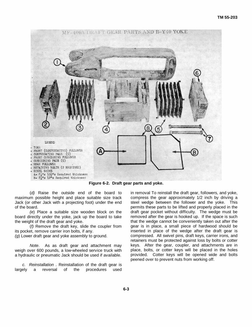
TM 55-203
Figure 6-2. Draft gear parts and yoke.
(d) Raise the outside end of the board tomaximum possible height and place suitable size trackJack (or other Jack with a projecting foot) under the endof the board.
(e) Place a suitable size wooden block on theboard directly under the yoke, jack up the board to takethe weight of the draft gear and yoke.
(f) Remove the draft key, slide the coupler fromits pocket, remove carrier iron bolts, if any.(g) Lower draft gear and yoke assembly to ground.
Note. As as draft gear and attachment mayweigh over 600 pounds, a low-wheeled service truck witha hydraulic or pneumatic Jack should be used if available.
c. Reinstallation . Reinstallation of the draft gear islargely a reversal of the procedures used
in removal To reinstall the draft gear, followers, and yoke,compress the gear approximately 1/2 inch by driving asteel wedge between the follower and the yoke. Thispermits these parts to be lifted and properly placed in thedraft gear pocket without difficulty. The wedge must beremoved after the gear is hooked up. If the space is suchthat the wedge cannot be conveniently taken out after thegear is in place, a small piece of hardwood should beinserted in place of the wedge after the draft gear iscompressed. All swivel pins, draft keys, carrier irons, andretainers must be protected against loss by bolts or cotterkeys. After the gear, coupler, and attachments are inplace, bolts, or cotter keys will be placed in the holesprovided. Cotter keys will be opened wide and boltspeened over to prevent nuts from working off.
6-3

TM 55-203
6-5. Maintenance
Established regulations of the Association of American
Railroads (AAR) and the Department of Transportation
(DOT) for the maintenance and inspection of freight and
passenger cars contained In current AAR interchange
rules are mandatory in interchange service on the
railroads of the United States. Although it is not
mandatory that Army personnel concerned with the
maintenance of railway freight and passenger cars in
oversea areas comply strictly with these regulations, it is
recommended that they be used as a guide, particularly
from a safety viewpoint.
6-6. Draft Gear for Oversea Equipment
The discussion on draft gears in paragraphs 6-1 through6-3 is applicable to railroad equipment in the continentalUnited States, Canada, and Mexico. The draft geardescribed for these countries is designed to take both buffand draft shocks. Of the oversea areas believed to bestrategically important, only China and Korea haveequipment where this type is adaptable. In most otherareas, only pull load is absorbed by the draft gear andbuff is absorbed by side buffers set approximately 35inches to each side of the centerline of the draft gear.The hook-and link coupler of European pattern and theWlllison coupler of Russian pattern are examples of thelatter type (fig 7-5 and 7-9).
6-4
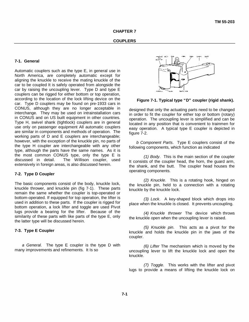
TM 55-203
CHAPTER 7
COUPLERS
7-1. General
Automatic couplers such as the type E, in general use inNorth America, are completely automatic except foraligning the knuckle to receive the mating knuckle of thecar to be coupled It is safely operated from alongside thecar by raising the uncoupling lever. Type D and type Ecouplers can be rigged for either bottom or top operation,according to the location of the lock lifting device on thecar. Type D couplers may be found on pre-1933 cars inCONUS, although they are no longer acceptable ininterchange. They may be used on intrainstallation carsin CONUS and on US built equipment in other countries.Type H, swivel shank (tightlock) couplers are in generaluse only on passenger equipment All automatic couplersare similar in components and methods of operation. Theworking parts of D and E couplers are interchangeable;however, with the exception of the knuckle pin, no parts ofthe type H coupler are interchangeable with any othertype, although the parts have the same names. As it isthe most common CONUS type, only the type E isdiscussed in detail. The Willison coupler, usedextensively in foreign areas, is also discussed herein.
7-2. Type D Coupler
The basic components consist of the body, knuckle lock,knuckle thrower, and knuckle pin (fig 7-1). These partsremain the same whether the coupler is top-operated orbottom-operated. If equipped for top operation, the lifter isused in addition to these parts. If the coupler is rigged forbottom operation, a lock lifter and toggle are used Pivotlugs provide a bearing for the lifter. Because of thesimilarity of these parts with like parts of the type E, onlythe latter type will be discussed herein.
7-3. Type E Coupler
a General. The type E coupler is the type D withmany improvements and refinements. It Is so
Figure 7-1. Typical type “D” coupler (rigid shank).
designed that only the actuating parts need to be changedin order to fit the coupler for either top or bottom (rotary)operation. The uncoupling lever is simplified and can belocated in any position that is convenient to trainmen foreasy operation. A typical type E coupler is depicted infigure 7-2.
b Component Parts. Type E couplers consist of thefollowing components, which function as indicated
(1) Body. This is the main section of the couplerIt consists of the coupler head, the horn, the guard arm,the shank, and the butt. The coupler head houses theoperating components.
(2) Knuckle. This is a rotating hook, hinged onthe knuckle pin, held to a connection with a rotatingknuckle by the knuckle lock.
(3) Lock. A key-shaped block which drops intoplace when the knuckle is closed. It prevents uncoupling.
(4) Knuckle thrower The device which throwsthe knuckle open when the uncoupling lever is raised.
(5) Knuckle pin. This acts as a pivot for theknuckle and holds the knuckle pin in the jaws of thecoupler.
(6) Lifter The mechanism which is moved by theuncoupling lever to lift the knuckle lock and open theknuckle.
(7) Toggle. This works with the lifter and pivotlugs to provide a means of lifting the knuckle lock on
7-1

TM 55-203
Figure 7-2. Typical type “E” coupler
c. Operation. To throw the knuckle (i.e., uncouple),the lock is lifted above its lockset position until thefulcrum on the forward side contacts the shoulder withinthe coupler head. This contact stops the verticalmovement of the lock and forces it to rotate about itsfulcrum, thus giving the lock key a positive movement tothe rear. This rotates the knuckle thrower about itstrunnions, and the lip of the thrower contacts the shoulderon the underside of the knuckle, throwing the knuckleopen, or unlocking It, if coupled to another.
7-4. Tightlock Couplers
The type H or tightlock coupler, of entirely new design,incorporates a number of distinct new features. Inoutward appearance, it is similar to those discussed andconsists of essentially the same named parts (para 7-2).Certain surfaces of the coupler head knuckle, lock andknuckle pinholes in both head and knuckle are machinefinished to meet the close fitting tolerances required. Inaddition, aligning wings extend from both sides of thecoupler head. These form a part of the head and provideincreased coupling efficiency. This type of coupler isrotary-operated and normally operated from the left sideof the car by a single-type lock-lift assembly. It can beadapted to a double-type lock-lift assembly for operationfrom either side. The principal advantages of this couplerdesign are the reduction of contour -slack, elimination ofnoise caused by coupler slack, the reduction of fatiguefailures in the coupler face and knuckle wall, andelimination of buffing stresses. Since slack is reducedand resulting buffing and jolting is also reduced, theservice lift of the coupler is increased.
7-5. Maintenance, CONUS-Type Couplers
a. General. Design specifications, requirements, andregulations will dictate when and what couplermaintenance action is to be accomplished. For CONUS-type couplers previously discussed, two of the morefrequent requirements for maintenance are cited below.Familiarity with AAR rules and Army regulations, as wellas with parts and their operational functions, is essentialfor good maintenance. Frequent inspections will detectdefective parts. Couplers, types D and E with distancebetween point of knuckle and guard arm exceeding 5 5/16inches as measured by gage (fig 7-3), must have thedefective part or parts renewed to bring coupler withinrequired gage of 5 1/8 inches as measured by gage (fig 7-4). If coupler is out of gage, the body must not berenewed unless the application of second-hand,reconditioned, or new knuckle lock and pin, any or all, willnot bring it within the required gage of 5 1/8 inches.
b. Coupler Height. Coupler height must bemaintained within the proper limits. The height of acoupler is measured from the top of the rail to the centerof the face of the coupler knuckle. Empty freight cars withcoupler heights measuring 32 1/2 inches or less will beadjusted to 34 1/2 inches. Loaded freight cars withcoupler heights measuring 31 1/2 inches or less will beadjusted to, but will not exceed, 33 1/2 inches. Whenadjusting coupler heights, the coupler should first beplaced in proper alinement with draft gear. Shim of 1/4-inch thickness or more, as required, may be applied to thecarrier iron to adjust coupler height. If a shim less than1/4inch thickness is required, realignment is unnecessary.After the coupler has been placed in
7-2

TM 55-203
Figure 7-3. Use of contour gage.
Figure 7-4. Use of worn limit gage.
proper alinement by shimming the carrier, if its heightis not at least 1/2 inch in excess of the minimumdimensions specified above, further adjustments shouldbe made at the truck springs, center plates, or journalboxes.
c. Knuckles. Excessive knuckle play, which ,oftenresults from exceptional shock and jar in switching, maycause the guard arm of the coupler to be bent out ofcontour This can cause the opening of the knuckle to beout of gage and allow the knuckle of the coupler of anadjoining car to slip out. The distance between the guardarm and the knuckle should meet gage requirements, notto exceed 5 1/8 inches, as shown in figure 7-4. Theknuckle opening may be exceptionally large. Thiscondition may be corrected by building up (by welding)the knuckle where it makes contact with the lock fulcrum.However, a new coupler may be installed under thesecircumstances. If the excessive opening is due to a wornknuckle in the knuckle pinhole, replacement of theknuckle may be required A knuckle worn on the face orback bearings will be condemned by gagging. Suchknuckles will be replaced. Knuckles are sometimes foundcracked down the face. Such cracks are dangerous, andthe knuckleshould be removed and replaced.
d. Knuckle Pins. Knuckle pins are frequently founddefective. When replaced, pins of the proper size mustbe used. Larger pins might crack the pinhole casting, andsmaller or undersized pins will become loose and willcreate slack, permitting the passing of the knuckle on theadjoining car between the knuckle and the guard arm.Cotter keys should not be used in knuckle pins except onfixed end gondola and hopper cars.
e. Slack. If any slack exists between the coupler buttand the follower plate or draft gear body, the cause shouldbe determined and remedial action taken. Slack usuallyis caused by a worn coupler butt, but may be due todefective draft gear (chap 6). Worn coupler butts may bebuilt up by electric welding or shim plates inserted toeliminate slack.
f. General Repairs. The rigid shank couplers incommon use on Army rolling stock are attached to thedraft gear yoke by draft keys inserted laterally throughholes in the yoke and coupler shank or butt. It issupported underneath by a coupler carrier (iron) securedto, or part of the underframe, and a shim or wear platebetween the carrier iron and the shank of the coupler. Toremove the coupler, the following procedure is used(assembly is in reverse order):
(1) Disconnect the uncoupling lever from thecoupler lock lifter.
(2) Remove knuckle pin and knuckle.
7-3

TM 55-203
(3) Remove lock, lock lifter, and knuckle thrower.
(4) Remove cotter keys or bolts from draft key.
(5) Drift out the draft key from tapered end.
(6) Slide the coupler backward until two thirds out.
(7) Place a long bar or pipe immediately behind thecoupler head, under the thickest portion of the shank, andwith two men holding the bar or pipe in one hand, eachside, using the other hand to balance the coupler, lift it outand lower to the ground.
(8) Remove yoke, draft gear, etc., as required (para 6-4b).
7-6. Couplers for Oversea Railway Equipment
With few exceptions, hook-and-link and Willison couplersset at 41 inches coupler height predominate in overseaareas. The exceptions are those areas such as Korea,Japan, and China where AAR-type automatic couplers areused. As stated previously, neither hook-and-link norWillison couplers transmit buff directly to the center sillthrough draft gear. Buff loads are taken up by two sidebuffers at coupler height above the top of the rail. Eachbuffer is set approximately 35 inches off the longitudinalcenterline of the car. Design loads are fixed for bothbuffers and the hook and links of the coupler. This designestablishes the maximum drawbar pull allowed whenfixing train tonnage’s, and the useful life of the coupler isdirectly related to the amount of misuse brought about byoverloading. One of the outstanding characteristics of thehook-and link coupler is that its design provides for nobuilt-in slack between cars. Links are turned tight byturnbuckles, thus losing all slack. These two couplingdevices are illustrated in figures 75 and 7-6. Figure 7-6shows side buffer arrangement.
7-7. Hook-and-Link Couplers
a. General. The standard European coupler consistsof three main parts on each end of the car. These partsare a screw coupling, a draw hook, and two bufferassemblies, illustrated in figure 7-. The draw hook formsa part of the underframe of the car. The screw coupling ismounted at the base of the hook. The two bufferassemblies are located one on each side of the hook andscrew coupling toward the outer sides of the car, asshown. The screw coupling consists
Figure 7-5. Hook and link (screw) coupler, buffer,and draft gear.
Figure 7-6. Side buffersof the clevis, screw and lever, and the shackle. Eachbuffer assembly consists of a housing which is attached tothe framework of the craft and in which is housed aspring-loaded section, extending out of the housing.
b. Operation. When cars are coupled, the shackle ofthe screw coupling on one car is
7-4

TM 55-203
hooked over the draw hook of the other car; tightening ofthe lever tightens the screw and draws up the screwcoupling The coupling is tightened until all slack isremoved. The face of each buffer on the car should thenbe in contact with the face of the corresponding buffer onthe other car. When the train is started or running, thescrew coupling carries the pulling load. In running,stopping, and starting, the buffers protect the cars andlading by obstructing any jolts and shocks and preventingthe cars from running together (the function of the draftgear in U. S. type equipment). On curves, the buffers onthe side of the cars on the inside of the curve are passedfarther into the housing The buffers on the outside of thecars extend from the housing because of the pressureexerted by the springs, thus they steady the car duringruns. To uncouple, the screw coupling lever must beloosened by loosening the screw until there is sufficientslack to lift the shackle off the draw hook.
7-8. Willison Automatic Couplers
a. General. The Willison coupler, used in someoversea areas, is an automatic coupler which works onthe same general principles as the standard AAR couplerused in the United States. It has one marked difference,that of being capable of coupling to the continentalEurope Standard hook-and-link coupling by means of atransition device, the standard clevis and screw discussedin paragraph 7-7. The principal components, shown infigure 7-7, include the following: friction buffer (1);Willison coupler (2); buffer spacer (3); coupler support (4);draft gear and yoke (5); and transition device (6). Theoperating parts of two types of Willlison coupler areillustrated in figures 7-8 and 7-9.
b. Maintenance The operating parts illustrated infigures 7-8 and 7-9 are removable and accessible formaintenance The following steps are taken in theinspection of this type coupler:
(1) Visually inspect the operating parts of thecoupler to see that they are not cracked or broken.
(2) Test uncoupling device for proper operation.(3) Check all visible parts of the draft gear for
cracks or damage(4) Measure coupler height. Centerline of coupler
should be 41 inches from top of rail. Buffer centerlinemust measure 42 inches from top of rail.
(5) Inspect friction buffers and transition screwdevice for loose, missing, or cracked parts.
c. Removal and Disassembly. The Willison typecoupler is removed from a car in the following manner:
(1) Disconnect uncoupling rigging(2) Support coupler weight and remove coupler
support from coupler by removing the four holding nutsand bolts.
(3) Remove the coupler pivot pin retaining keythrough the cut-out hole provided in the side of thecoupler and drop out the pin.
(4) Disconnect coupler from draft gear yoke andpull out to remove.
(5) Remove thrower arm bolt and nut(6) Remove thrower, lock, and filler block.(7) Clean and inspect all parts for serviceability.
d. Reassembly
(1) Replace all damaged or worn parts.(2) Assemble and install parts in reverse order of
removal.(3) Gage coupler height when installation In the
car has been completed. Adjust as required.
7-5

TM 55-203
Figure 7-7. Typical Willison arrangement.
Figure 7-8. Operating parts, type E, Willison coupler.
7-6

TM 55-203
Figure 7-9. Operating parts type L, Willison coupler.
7-7

TM 55-203
CHAPTER 8
CAR BRAKE EQUIPMENT
Section I. CAR TRUCK BRAKE GEAR
8-1. General
a. Brake gear is the whole combination of parts ona car or train which, when working together, slow downor stop the motion of the car or train These parts includethe foundation brake system. On many oversearailways, a vacuum brake system is used in lieu of thestandard airbrake system found in the United States.
b. A truck brake assembly includes those parts ofthe foundation brake gear that are secured directly tothe truck. It includes the truck live lever, bottomconnecting rod, bottom brake rod and brake beamsafety supports, truck dead lever, dead-lever fulcrum,brake beams, brake beam heads, brakeshoes, and allkeys, pins, etc, needed to make the assembly complete(fig 4-29). The dividing point is the connection of thetruck live lever with the remainder of the foundationgear.
c. Foundation brake gear parts, including thoseparts known as truck brake gear parts, are standardizedby regulations and specifications Required braking ratiosare fixed by Association of American Railroad (AAR)regulations which are strictly adhered to. Theseregulations are incorporated in Department of the Armyspecifications for all railway equipment for both overseaand domestic service.
d. Certain railway equipment such as depressedcenter flatcars and exceptionally long passenger cars,such as circus train cars, because of low congestedcenter sections on their underframes, require separatebrake cylinders mounted on each truck for effectivebraking action in lieu of the conventional single body-mounted brake cylinder and foundation brake gear.This difficulty is circumvented by mounting completeand independent brake cylinders with foundation brakegear on each truck.
8-2. Foundation Brake Gear
a. General. The foundation brake gear (fig 8-1, 8-2) is defined as levers, rods, brakeshoes, brake beams,
and similar equipment either secured directly to the cartrucks or associated with the car trucks throughcomponent parts of the system. These parts connectthe brakeshoes to the handbrake system and to thepiston rod of the brake cylinder of the airbrake system.This connection is so made that, when the handbrakewheel is operated or the air pressure forces the pistonout, the brakeshoes are forced against the wheels Thisaction slows down or stops the car or train, dependingupon its speed, the extent of brake application, and thefrequency of application. Brake beams, brakeshoes,levers, etc., are illustrated in figure 4-29.
b. Brake Lever Badge Plate
(1) A standard badge and dimension plateshowing the dimensions of the truck and body leverswhich are standard for each car was adopted by theAssociation of American Railroads in 1928.
(2) The badge plate (fig 8-2) is made of metaland fastened to the underframe of the car in anaccessible place, preferably near the brake cylinder.This plate gives the proper dimensions of the levers forboth the body and truck brake gear. After an approvedbadge plate has been applied to any car, levers will bechecked to see that they conform to standarddimensions. These requirements are a part of the rulesin effect on all railroads governing annual repairs tobrakes on freight cars. If wrong levers are found, theywill be replaced with levers conforming to thedimensions shown on the badge plate.
8-3. Brake Gear Regulators
a. General. Several types of brake gear regulatorsare in use on freight cars. These regulators take upslack manually in the brake gear to adjust piston travel.Automatic slack adjusters (fig 8-3) must be properlyregulated each time piston travel is adjusted to insurethat sufficient takeup is available to maintain properpiston travel en
8-1

TM 55-203
Figure 8-1. Foundation brake gear diagram.
route in service. Maintenance is described inparagraphs 16-7 and 8-19. Three of these regulatorsare described below.
b. Type 1. One type is provided with a notchedpull rod at each end of the car which is connected to thedead lever. To adjust piston travel: pull straight on thehandle which is located on the right side of the couplerand let go. A pawl on the notched pull rod locks whenthe rod is pulled as far as it will go. Then go to theopposite end of the car and repeat the operation. Torelease slack to change brakeshoes, pull handle, thengive it 1/8 turn to right, then push back all the way. Thisgives maximum slack in the brake.
c. Type 2. Another type is provided with a rigginglever which extends in a horizontal position to a pointnear and just under the outer ledge of the car near thecenter, or in some applications on hopper cars it islocated at one end. The lever actuates a notchedsquare bar, which has a pawl underneath the bar,
engaging the notches. A single lever serves to take upslack on both trucks. To adjust piston travel: pull thehandle of the lever as far as it will go, then release. Torelease slack: push up pawl, then push back handle asfar as it will go.
d. Type 3. A third type is provided with a rotatingsquare shaft, which is placed in a horizontal positionunder the car body, extending out under the outer sill ofthe car. Two holes are drilled through the end of thesquare shaft. A short bar can be inserted in the hole onany of the four sides. A pawl wheel is 'placed on theshaft, and the direction -to turn shaft to take up slack isindicated by an arrow on the housing inclosing the pawlwheel. To take up slack: insert a short bar in hole in endof shaft, and turn shaft in direction indicated by arrow asfar as it will go, then release. To release slack: releasepawl and turn shaft as far as it will go in oppositedirection. Adjustments for this type are shown in figure8-4.
8-2

TM 55-203
Figure 8-2. Typical brake lever badge and dimension plate.
8-3

TM 55-203
Figure 8-3. Brakes regulator, automatic type.
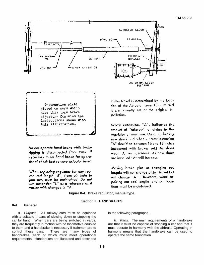
TM 55-203
Figure 8-4. Brake regulator, manual type.
Section II. HANDBRAKES8-4. General
a. Purpose. All railway cars must be equippedwith a suitable means of slowing down or stopping thecar by hand. When cars are being switched in yards,they are frequently in motion with no locomotive coupledto them and a handbrake is necessary if trainmen are tocontrol these cars. There are many types ofhandbrakes, each of which must meet operationalrequirements. Handbrakes are illustrated and described
in the following paragraphs.
b. Parts. The main requirements of a handbrakeare that it must be capable of stopping a car and that itmust operate in harmony with the airbrake Operating inharmony means that the handbrake can be used tooperate the same foundation
8-5
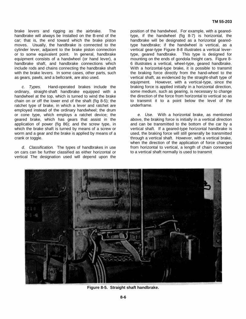
TM 55-203
brake levers and rigging as the airbrake. Thehandbrake will always be Installed on the B-end of thecar; that is, the end toward which the brake pistonmoves. Usually, the handbrake is connected to thecylinder lever, adjacent to the brake piston connectionor to some equivalent point. In general, handbrakeequipment consists of a handwheel (or hand lever), ahandbrake shaft, and handbrake connections whichinclude rods and chains connecting the handbrake shaftwith the brake levers. In some cases, other parts, suchas gears, pawls, and a bellcrank, are also used.
c. Types. Hand-operated brakes include theordinary, straight-shaft handbrake equipped with ahandwheel at the top, which is turned to wind the brakechain on or off the lower end of the shaft (fig 8-5); theratchet type of brake, in which a lever and ratchet areemployed instead of the ordinary handwheel; the drumor cone type, which employs a ratchet device; thegeared brake, which has gears that assist in theapplication of power (fig 86); and the screw type, inwhich the brake shaft is turned by means of a screw orworm and a gear and the brake is applied by means of acrank or toggle.
d. Classification. The types of handbrakes in useon cars can be further classified as either horizontal orvertical The designation used will depend upon the
position of the handwheel. For example, with a geared-type, if the handwheel (fig 8-7) is horizontal, thehandbrake will be designated as a horizontal geared-type handbrake; if the handwheel is vertical, as avertical gear-type Figure 8-8 illustrates a vertical lever-type, geared handbrake. This type is designed formounting on the ends of gondola freight cars. Figure 8-6 illustrates a vertical, wheel-type, geared handbrake.With a horizontal-type brake, it is possible to transmitthe braking force directly from the hand-wheel to thevertical shaft, as evidenced by the straight-shaft type ofequipment. However, with a vertical-type, since thebraking force is applied initially in a horizontal direction,some medium, such as gearing, is necessary to changethe direction of the force from horizontal to vertical so asto transmit it to a point below the level of theunderframe.
e. Use. With a horizontal brake, as mentionedabove, the braking force is initially in a vertical directionand can be transmitted to the bottom of the car by avertical shaft. If a geared-type horizontal handbrake isused, the braking force will still generally be transmittedthrough a vertical shaft. However, with a vertical brake,when the direction of the application of force changesfrom horizontal to vertical, a length of chain connectedto a vertical shaft normally is used to transmit
Figure 8-5. Straight shaft handbrake.
8-6

TM 55-203
Figure 8-6. Vertical geared-type handbrake, 50-ton USA boxcar, showing retainer valve.
the braking force beneath the car. When the straightshaft is used, it will rotate as the handwheel is turned.When the chain is used, it will rise upon brakeapplication and wind on a small shaft or drum or it willlower upon brake release, thus unwinding. When thebraking force reaches a point below the level of theunderframe, it must change direction to connect to thefoundation brake rigging levers and rods and thusoperate the brakeshoes.
8-5. Design
a. Early Straight-Shaft Design. The straightshaftdesign consists of a handwheel or hand lever, a shaftrunning vertically along the end of the car and anchored
to a bracket on the underframe, and the horizontal brakechain fastened to the end of the vertical shaft. A gearand pawl, usually near the top of the vertical shaft,prevent the equipment from backing off. When thehand- wheel is turned to apply the brakes, the shaft andthe gear turn, and the pawl engages each tooth of thegear, preventing backing off. Simultaneously, thehorizontal brake chain winds around the turning shaftand applies the brakes. To release the brakes, the pawlshould be disengaged and the handwheel turned in theopposite direction to permit the chain to unwind from thevertical shaft. A variation of the straight-shaft type,embodying the same principle as the gear type, is tohave the end of the shaft anchored to the under-
8-7

TM 55-203
Figure 8-7. Typical horizontal-type handbrakes.
frame, with a spur gear installed on the shaft.Sometimes the shaft may be bent to such an extent thatthe brake will be inoperative. When a bent shaft isnoticed, the brake should be tested to see whether thebend is prohibitive Also, where the chain winds aroundthe shaft, the chain must be properly secured at thebottom to the underframe. The ratchet wheel and pawl,where exposed, should be inspected to see that both thewheel and pawl are secure, that they operate properly tohold the brake in any position, and that the brakereleases properly when the pawl is released.
Figure 8-8. Vertical, lever-type, geared handbrakes.
b. Geared Handbrakes. Geared handbrakes are ofthree types-horizontal, vertical, and lever. All typesoperate in a similar manner. The handbrake operates inharmony with the power brake, and the design is suchthat, when force is applied to the brake cylinder lever atthe brake piston connection, it permits a movement ofnot less than 14 inches. Also, when the brake piston isin full-release position, there is no excess slack in thehandbrake chain or in other connections. The brakewheel and drum are arranged so that both revolve whenthe handbrake is applied or gradually released.Standard 9/16-inch hand chains or minimum 3/4-inch-diameter rods are used.
8-6. Maintenance
a. Lubrication. When cars are on shop or repairtracks for periodic attention to airbrakes, the gearedhandbrake mechanism and connections
8-8
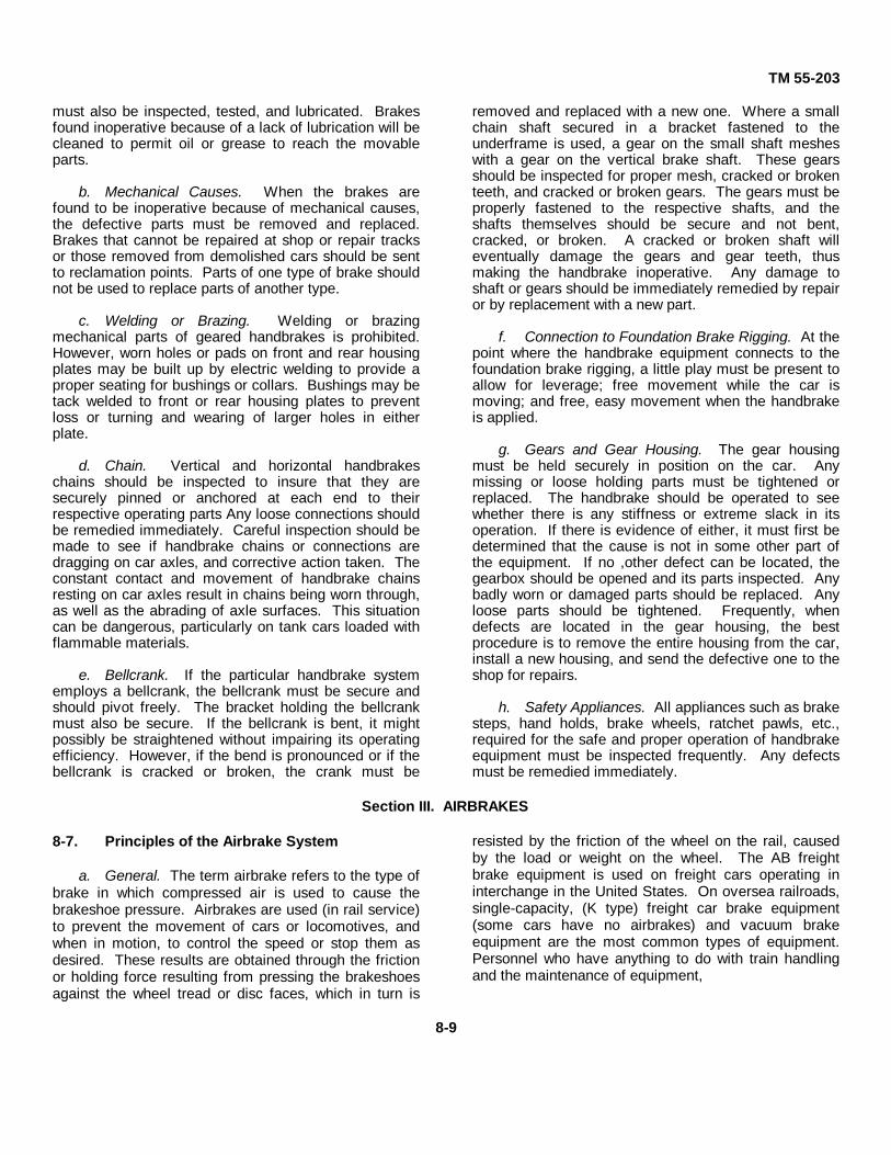
TM 55-203
must also be inspected, tested, and lubricated. Brakesfound inoperative because of a lack of lubrication will becleaned to permit oil or grease to reach the movableparts.
b. Mechanical Causes. When the brakes arefound to be inoperative because of mechanical causes,the defective parts must be removed and replaced.Brakes that cannot be repaired at shop or repair tracksor those removed from demolished cars should be sentto reclamation points. Parts of one type of brake shouldnot be used to replace parts of another type.
c. Welding or Brazing. Welding or brazingmechanical parts of geared handbrakes is prohibited.However, worn holes or pads on front and rear housingplates may be built up by electric welding to provide aproper seating for bushings or collars. Bushings may betack welded to front or rear housing plates to preventloss or turning and wearing of larger holes in eitherplate.
d. Chain. Vertical and horizontal handbrakeschains should be inspected to insure that they aresecurely pinned or anchored at each end to theirrespective operating parts Any loose connections shouldbe remedied immediately. Careful inspection should bemade to see if handbrake chains or connections aredragging on car axles, and corrective action taken. Theconstant contact and movement of handbrake chainsresting on car axles result in chains being worn through,as well as the abrading of axle surfaces. This situationcan be dangerous, particularly on tank cars loaded withflammable materials.
e. Bellcrank. If the particular handbrake systememploys a bellcrank, the bellcrank must be secure andshould pivot freely. The bracket holding the bellcrankmust also be secure. If the bellcrank is bent, it mightpossibly be straightened without impairing its operatingefficiency. However, if the bend is pronounced or if thebellcrank is cracked or broken, the crank must be
removed and replaced with a new one. Where a smallchain shaft secured in a bracket fastened to theunderframe is used, a gear on the small shaft mesheswith a gear on the vertical brake shaft. These gearsshould be inspected for proper mesh, cracked or brokenteeth, and cracked or broken gears. The gears must beproperly fastened to the respective shafts, and theshafts themselves should be secure and not bent,cracked, or broken. A cracked or broken shaft willeventually damage the gears and gear teeth, thusmaking the handbrake inoperative. Any damage toshaft or gears should be immediately remedied by repairor by replacement with a new part.
f. Connection to Foundation Brake Rigging. At thepoint where the handbrake equipment connects to thefoundation brake rigging, a little play must be present toallow for leverage; free movement while the car ismoving; and free, easy movement when the handbrakeis applied.
g. Gears and Gear Housing. The gear housingmust be held securely in position on the car. Anymissing or loose holding parts must be tightened orreplaced. The handbrake should be operated to seewhether there is any stiffness or extreme slack in itsoperation. If there is evidence of either, it must first bedetermined that the cause is not in some other part ofthe equipment. If no ,other defect can be located, thegearbox should be opened and its parts inspected. Anybadly worn or damaged parts should be replaced. Anyloose parts should be tightened. Frequently, whendefects are located in the gear housing, the bestprocedure is to remove the entire housing from the car,install a new housing, and send the defective one to theshop for repairs.
h. Safety Appliances. All appliances such as brakesteps, hand holds, brake wheels, ratchet pawls, etc.,required for the safe and proper operation of handbrakeequipment must be inspected frequently. Any defectsmust be remedied immediately.
Section III. AIRBRAKES
8-7. Principles of the Airbrake System
a. General. The term airbrake refers to the type ofbrake in which compressed air is used to cause thebrakeshoe pressure. Airbrakes are used (in rail service)to prevent the movement of cars or locomotives, andwhen in motion, to control the speed or stop them asdesired. These results are obtained through the frictionor holding force resulting from pressing the brakeshoesagainst the wheel tread or disc faces, which in turn is
resisted by the friction of the wheel on the rail, causedby the load or weight on the wheel. The AB freightbrake equipment is used on freight cars operating ininterchange in the United States. On oversea railroads,single-capacity, (K type) freight car brake equipment(some cars have no airbrakes) and vacuum brakeequipment are the most common types of equipment.Personnel who have anything to do with train handlingand the maintenance of equipment,
8-9

TM 55-203
either directly or indirectly, must thoroughly understandthe elementary functions and operating principles ofairbrakes. Such an understanding is the largestcontributing factor to safety and economy and theprevention of loss of life or damage to railroad rollingstock and lading.
b. Operation. The necessity for accurate andpositive control of railway trains requires the use ofefficient brakes and has led to the development of themodern airbrake. The use of airbrakes is compulsory onAmerican railways, and this apparatus has beendeveloped to a high state of efficiency. The termairbrakes includes any brake operated by air pressure,but usually is restricted to systems of continuous brakesoperated by compressed air as generally used inAmerican railway practice to distinguish them fromvacuum brakes. Air is compressed by a pump on thesteam locomotive or by a motor compressor on electricor internal-combustion locomotives or cars stored inreservoirs, and is conveyed by pipes and flexible hosebetween the cars to cylinders and pistons under eachcar. Under the cars the pressure is transmitted to thebrake levers and thence to the brakeshoes. The brakesare applied by reducing the pressure in the brake pipebelow that in the auxiliary reservoirs. Such a reductionis caused when the engineman opens the brake pipe tothe atmosphere through the brake valve, or accidentallywhen a hose bursts or a pipe breaks. The brakes arereleased by admitting compressed air from the mainreservoir on the locomotive through the brake valve intothe brake pipe, thus increasing the air pressure abovethat remaining in the auxiliary reservoir.
8-8. Principal Parts of the Automatic Brake
a. A power-driven air compressor, which suppliescompressed air for use in the brake and signal system.
b. A governor, which controls compressoroperation and regulates the air pressure maintained inthe main reservoir.
c. Main reservoirs, which serve three purposes:
(1) To receive and store the compressed air.
(2) To act as a cooling chamber for thecompressed air and as a catch basin for moisture and oilwhich is passed from the compressor and precipitatedfrom the air by cooling.
(3) To act as a storage chamber for expresspressure for operating other air-using devices withoutinterfering with brake pipe pressure, and to serve as a
backing volume or driving head of excess pressure forthe purpose of releasing the brakes and recharging theairbrake system.
d. Two duplex gages (located in locomotive cab),one indicating main reservoir and equalizing reservoirpressure, the other, brake pipe and brake cylinderpressure. In addition, on dieselelectric passengerlocomotives with high-speed control brake equipment,another single pointer gage in the cab shows controlpipe pressure, while a single pointer gage in the engine-room of each unit shows main reservoir pressure. Ondiesel-electric freight locomotives with No. 8 ELequipment, three duplex air gages are located in thecab, one indicating main reservoir and equalizingreservoir pressure, a second indicating brake pipe andlocomotive brake cylinder pressure, and a thirdindicating application and suppression pipe pressure. Asingle pointed gage indicating main reservoir pressure islocated in the engineroom of each unit.
e. An automatic brake valve (located in locomotivecab), which regulates the flow of air from the mainreservoirs into the brake pipe for releasing the brakesand from the brake pipe to the atmosphere for applyingthe brakes. A feed valve controls and reduces mainreservoir pressure passing through the brake valve tothe brake pipe in running position of the automatic brakevalve.
f. A brake pipe (including branch pipe, flexiblehose, and couplings), which connects the locomotiveautomatic brake valve and the conductor's valve withthe brake control valve on each car. Angle cocks areprovided at each end of every car for opening or closingthe brake pipe at any desired point in the train. Cutoutcocks are located in the branch pipe or crossover pipe tothe brake control valve under each car to cutoutindividual brakes.
g. A brake control valve on each car to which thebrake pipe, auxiliary reservoir, brake cylinder, andpressure retaining valve are connected, which performsthree functions: first, to charge the auxiliary reservoirfrom the brake pipe; second, to admit air from theauxiliary reservoir to the brake cylinder to apply thebrake; and third, to exhaust air from the brake cylinderto the atmosphere to release the brake. The AB typebrake, used on freight cars operating in CONUS, isprovided with an additional valve and reservoir whichare used to provide additional braking power inemergency situations.
h. An auxiliary reservoir (also an emergencyreservoir with the AB type brakes) on each car in whichcompressed air is stored for applying the brakes.
8-10

TM 55-203
i. A brake cylinder or cylinders on each car,provided with a piston rod connected with the brakelevers in such a manner that when the piston is movedby air pressure the brakes are applied.
j. A pressure-retaining valve that permits thebrake cylinder air to be freely exhausted to theatmosphere or retards the exhaust of air from the brakecylinder down to a predetermined pressure and thenretains that amount.
8-9. Definition of Term Used
a. Increase In Brake Pipe Pressure. When air ispassing into the brake pipe more rapidly than it isescaping, so as to produce a rise in pressure (brake pipepressure increase), it will move the control valves torelease position.
b. Maintaining Brake Pipe Pressure. With theautomatic brake valve in running position, air is beingsupplied to the brake pipe as fast as it is escaping. Thefeed valve automatically supplies brake pipe losses.
c. Brake Pipe Reduction. Air is escaping or beingdischarged from the brake pipe faster than it is beingsupplied through the brake valve, or feeding back fromthe auxiliaries. Losses from the brake pipe that are notbeing supplied will constitute a brake pipe reduction andtend to cause the brake control valves to move towardapplication position.
d. Lap. This term designates the position of thelocomotive brake valve and brake control valves ordistributing valve, in which all operative parts are closedto the passage of air.
e. Brake Application. A sufficient reduction ofbrake pipe pressure (no matter how made) to cause thebrake control valves, or distributing valve, to move toapplication position. If made with the locomotive brakevalve in service position, it may consist of one or morereductions with brakes remaining applied.
f. Service Application. A quick, heavy reduction ofbrake pipe pressure so as to cause the brake controlvalves to move to service application position. Thiscondition is accomplished by the locomotive engineerfor an expected stop or slow down or when a gradualreduction is made with the conductor's valve or tailhose.
g. Emergency Application. A quick heavyreduction of brake pipe pressure which will cause thebrake control valves to move to emergency position andtransmit quick action. This condition is accomplishedwhen the locomotive brake valve is placed inemergency position, or by the trainmen with theconductors valve or tail hose. It is also madeautomatically when the brake pipe is broken or when thetrain parts.
Section IV. AB FREIGHT BRAKE EQUIPMENT
8-10. General
a. In 1926, the Association of American Railroadsin cooperation with the Interstate CommerceCommission inaugurated a series of tests of varioustypes of airbrake equipment for freight train brakes.Rack tests were followed by road tests. These resultedin adoption of an approved freight brake which has beengiven the designation AB. Additional equipment nowavailable includes:
(1) AB-1-B brake equipment for highspeedfreight or passenger service.
(2) AB-4-12 brake equipment for heavy freightcars.
(3) AB Automatic Empty and Load brakeequipment used generally on high-capacity gondola andhopper cars operating primarily in coal or ore servicewhere they operate empty or fully loaded.
b. The performance and maintenance of the AB-
4-12 and the AB Automatic Empty and Load brakes arepractically the same as the AB brakes with minorvariations. Therefore, only the AB and AB-1-B brakeswill be covered in the following paragraphs.
8-11. Description
a. AB Freight Brake. The AB freight brake wasdeveloped to keep pace with other major improvements.All of the good operating features of the standard brakehave been retained and other valuable ones added.The AB brake has been adopted by the Association ofAmerican Railways (A.A.R.) as standard freight brake.Following are some of the approved features in the ABbrake that were not included in the K freight brake.
(1) Improved quick service. The three stagesof quick service provide a prompt and positive brakeapplication on all cars of long modern trains.
(2) Improved release. In case of excessiveslide valve friction that may delay release (or cause astruck brake), a release insuring valve
8-11

TM 55-203
automatically releases the brake by reducing auxiliaryreservoir pressure.
(3) Rapid recharge. A rapid increase of brakepipe pressure is obtained when release is started byusing the emergency reservoir (which remains fullycharged during a service application).
(4) Improved emergency. Undesiredemergency during service application is eliminated byseparation of the parts controlling the service andemergency portion.
(5) Emergency brake cylinder pressure.Emergency brake cylinder pressure approximately 20percent higher than that obtainable from a full servicebrake application.
(6) Speed of emergency. Speed of emergencythrough the train is approximately 40 percent faster thanthe former standard freight brake.
(7) Development of emergency pressure.Development of emergency brake cylinder pressure insteps at a controlled rate prevents damaging shocks.Emergency pressure is available at all times.
b. AB-1-B Freight Brake. The AB-1-B brake is thesame as the standard AB brake equipment with theaddition of a filling piece with a selector valve portion,which is applied between the pipe bracket andemergency portion of the AB control valve. The serviceand emergency portions are standard in all respects tothe AB control valve, but the studs holding the fillingpiece and emergency portion to the pipe bracket arelonger than standard.
8-12. AB and AB-1-B Brake System Components
The components for both the AB and AB-1-B brakesystems are the same unless otherwise noted:
a. AB Control Valve (used with AB brakes). TheAB valve (fig. 8-9) consists of the following components:
(1) A pipe bracket, which is permanentlymounted on the car and carries the pipe connections sothat no pipes need to be disconnected to remove avalve portion. It also contains a removable hair strainerto keep foreign matter out of the valve portions.
(2) The service portion, which controls thecharging of the reservoirs and the service applicationand release of brakes.
(3) The emergency portion, which controls thequick-action feature, high brake cylinder pressure, and
the accelerated emergency release function.b. AB-1-B Control Valve (used with AB-1-B brakes)
(1) The AB-1-B control valve is the same as thestandard AB control valve except for the addition of afilling with selector valve portion and longer emergencyportion bolting studs. The filling piece is bolted onbetween the pipe bracket and the emergency portion.
(2) A safety valve is provided on the selectorvalve portion which limits brake cylinder pressure forsevere brake applications, but is closed off from thebrake cylinder in emergency. The proper setting for thesafety valve is 60 pounds.
(3) A connection is made from the signal line tothe filling piece which automatically adjusts the selectorvalve for either passenger or freight service. Whenoperated in passenger service, signal pressureautomatically adjusts the selector valve to provide adirect build-up of emergency brake cylinder pressure.
(4) When operated in freight service, theabsence of signal line pressure automatically adjusts theselector valve to provide the standard three-stagedevelopment of emergency brake cylinder pressure.
(5) In service braking the operation of this equipment isthe same as the AB equipment.
c. A-2-A Quick-Service Valve (When Equipped).The A-2-A quick-service valve (fig 8-10) insures promptbrake pipe reduction and positive brake application.
d. Brake Cylinder (Fig 8-11)
(1) The brake cylinders are equipped with apiston and rod connected through the brake levers,brake rods, and brakeshoes. When the piston is forcedoutward by the air pressure, force is transmitted throughthe rods and levers applying the brakeshoes to thewheels. A release spring forces the piston to the releaseposition when air pressure is exhausted from theopposite end of the cylinder. A packing cup pressesagainst the cylinder walls and prevents the escape of airpast the piston.
(2) Periodic cleaning, oiling, and testing of thebrake cylinder is performed without removing thecylinder from the car.
e. Combined Auxiliary and Emergency Reservoir.The auxiliary and emergency reservoirs are combinedinto one unit (fig. 8-12) which is divided into twocompartments. One serves as storage for auxiliary airpressure and the other for
8-12

TM 55-203
Figure 8-9. AB valve showing the operating portions with pipe bracket sectioncut away to show strainer.
8-13

TM 55-203
Figure 8-10. Exterior view of A-2-A quick-servicevalue.
emergency air pressure. Letters cast on a lug projectingfrom the separation plate identify the reservoirs. Theletters AUX on one side of the lug indicate the auxiliaryreservoir and the letters EMERG on the other side of thelug indicate the emergency reservoir.
f. Automatic Air-Operated Slack Adjuster (whenequipped)
(1) The automatic slack adjuster (fig 8-3) is adevice for maintaining a uniform running standard pistontravel.
(2) The piston travel, when over that for whichthe adjuster is set, is automatically shortened by a smallcylinder having a piston with a pawl which engages withand turns the ratchet nut The adjuster cylinder takes airfrom the brake cylinder through a small pipe which istapped into the brake cylinder at a distance from thepressure head approximately equal to the desired pistontravel.
(3) When piston travel allows the pistonpacking cup to pass the port where the adjuster pipe isconnected to the cylinder, brake cylinder pressure isadmitted to the adjuster cylinder which moves the pistonthe full stroke of the cylinder, compresses a spring andmoves the pawl over two teeth of the ratchet nut.
(4) When the airbrake is released and the brakecylinder piston moves back past the port, the air in theadjuster cylinder exhausts into the nonpressure end ofthe brake cylinder. This permits the piston spring in theadjuster cylinder to force back the adjuster piston, andby means of the pawl makes 1/8 of a turn of the ratchetnut.
g. Combined Dirt Collector and Cutout Cock. A
combined dirt collector and cutout cock (fig 8-13) isconnected in the brake pipe leading to the pipe bracket.It prevents pipe scale, sand, cinder, and other foreignmatter from entering the AB valve. The umbrella-shaped check valve retains in the dirt chamber thecollected dirt accumulated during airbrake operation. Toremove the dirt chamber for cleaning, remove the twonuts securing the chamber to the collector body.
h. Branch Pipe Tee. The branch pipe tee (fig 8-14)connects the branch pipe to the brake pipe. It preventsexcessive moisture that may be deposited in brake pipefrom passing into the branch pipe and thence to the ABvalve.
i. Retaining Valve.
(1) The retaining valve is a three-position,manually operated, pressure-retaining exhaust valve(fig. 8-15). The valve is usually fastened to the end ofcar near the brake staff The handle positions are plainlyidentified as follows:
(a) EX (Direct Exhaust) handle pointingdownward.
(b) HP (High Pressure Retain) handle 45° to60° clockwise from EX position.
(c) SD (Slow Direct Exhaust) handle 135°to 1500 clockwise from EX position.
(2) The retaining valve is calibrated to regulatethe air pressure as follows:
(a) With the handle in direct exhaust thebrake cylinder pressure exhausts freely to theatmosphere.
(b) With the handle in high pressure retainit retards the exhaust of air from the brake cylinder downto a predetermined pressure and then retains thatamount (approximately 16 to 22 psi).
(c) With the handle in slow direct exhaustthe brake cylinder pressure exhausts slowly to theatmosphere.
(3) The calibration of the retaining valve is suchas to permit the blowdown of a 435-cubic-inch reservoirvolume from an initial charge 80 psi pressure for each ofits three positions in the time specified below:
Position Pressure blowdown Time (in seconds)
Direct Exhaust 70 to 10 psi Less than 3seconds
High PressureRetain 60 to 40 psi 33 to 43 seconds
Slow DirectExhaust 60 to 40 psi 17 to 22 seconds
8-14

TM 55-203
Figure 8-11. Assembly view of the AB-A brake cylinder with lever brackets.
Note. Prior to 1967, some care were equippedwith a two-position retaining valve to control brakecylinder pressure. With the handle In down position, thebrake cylinder air exhausts freely to the atmosphere.With the handle in up position, it retards the exhaust ofair from the brake cylinder down to a predeterminedpressure and then retains that amount.
j. Angle Cocks. Angle cocks with hoseconnections and couplings are connected on the ends ofthe brake. They provide a flexible connection betweenthe brake pipes on adjoining cars.
8-13. Cleaning and Testing AB Brakes on RepairTrack
a. Requirements. The complete brake equipmentmust be cleaned, oiled, tested, and stenciled (COT&S)as follows:
(1) After expiration of 48 months as indicatedby the stencil marking on car; and may be given COT&Sattention after expiration of 45 months when the car ison the repair track regardless of whether or not it needsother repairs.
(2) When airbrakes are inoperative due tofailure to pass the Single Car Test Device Code ofTests, unless the inoperative condition is due to renewalof pipes and fittings (including flange and compression
type) duplex release valve part, vent protector, brakereservoir, combined dirt collector and cutout cock,branch pipe tee, retaining valve or parts of these items.
(3) When stenciled markings as required aremissing, incorrect, or indistinct.
b. Cleaning
(1) To secure the required external clearancesand reduce the cleaning time to a minimum, thefollowing tools and equipment are required by the brakecleaning personnel for performing their respectivefunctions:
(a) An open end S wrench with 3/4-inch and13/16-inch openings, for dirt collector, branch pipe tee,and cutout cock.
(b) Combination socket wrench set for ABvalve portions, flange fittings, and brake cylindernonpressure head. The set consists of one ratchet-typehandle, two extensions, one universal joint, and fivesockets in sizes 9/16- inch, 5/8-inch, 3/4-inch, 13/1.6-inch, and 1 inch. The 13/16-inch socket is required onlyfor the AB empty and load changeover valve.
(c) Strainer nut wrench for brake pipestrainer nuts, used with handle and extensions listed in(b) above.
8-15

TM 55-203
Figure 8-12. Combined auxiliary and emergency reservoir.
(d) Blowing nozzle valve with suitable 1/4-inch pipe nipple nozzle for blower hose.
(e) Shipping covers and vent protector plugas per brake manufacturer's standard for protecting ABvalve portions in transit.
(f) Suitable covers or containers to protectthe AB brake cylinder piston, hollow rod andnonpressure head assemblies from dirt or damageshould be provided when transporting assemblies to andfrom the car.
(g) A grease can arranged so that both thegrease and brush can be protected against dirt.
(2) Record the car number, owner, and lastcleaning date. All old cleaning marks must be scrapedoff and painted over with quick-drying black paint.
(3) Close the branch pipe cock and drain the airout of the auxiliary reservoir, emergency reservoir, andbrake cylinder. Remove the cup from the dirt collectorand leave it off until cleaned valve portions are applied.Disconnect the release valve lever, leaving it attachedto the release rods.
(4) Blow any dirt or water out of the yard air lineand supply hose connection to car. If the brake testsare to be made by the men who clean the brake, couplethe single car tester to the yard air line and the car brakepipe at the B-end of the car. Otherwise, couple the yardair supply directly to the car brake pipe. Charge thebrake pipe, and leave the yard air supply connected toit. Blow out the brake pipe by opening the angle cock atthe A end of car, and then apply a dummy coupling orthe blower hose to the A end of the car and leave bothangle cocks open. Open the branch pipe cock to blowdirt from the branch pipe, then close it.
(5) Scrape, wipe, and blow off all dirt adjacentto the gaskets between -the pipe bracket and the valveportions, then using the blower hose, blow off all loosedirt on the AB valve portions, pipe bracket, hopperslopes, car underframes, etc., that may otherwise getinto the AB valve portions or pipe bracket when theportions are being removed and clean portions applied.
Note. The operating portions of the AB controlvalve or parts thereof must never be dismantled or haveany parts removed or replaced on the car. All cleaningand relubrication of the valve portions must beaccomplished by competent airbrake mechanics in awell- lighted location.
8-16

TM 55-203
Figure 8-13. Combined dirt collector and cutoutcock.
Figure 8-14. Branch pipe tee for AB brake.
Figure 8-15. Sectional view of standard retainingvalve.
c. Remove AB Valve Service Portion(1) Disconnect the brake cylinder release rod.
Remove the three nuts from mounting studs and slidethe valve portion off the studs.
(2) Remove the brake pipe strainer and place itin the shipping cover. Immediately apply the cover tothe service portion and tighten the holding nuts. Theshipping cover must be applied to prevent entrance ofdirt, water, or damage to internal parts whentransporting the valve to the airbrake shop forreconditioning (para 8-15).
d. Remove AB Valve Emergency Portion
(1) Remove vent protector and plug theopening with a vent protector plug.
(2) Remove the three nuts from the mountingstuds and slide the valve portion off the studs.
(3) Move the piston into release position andimmediately apply the shipping cover and tighten theholding nuts. The cover must be applied to prevententrance of dirt, water, or damage to internal parts whentransporting the valve portion to the airbrake shop forreconditioning (para 8-15).
e. Remove Retaining Valve(1) Unscrew the exhaust pipe from the elbow
and uncouple inlet air line at the union.(2) Remove the nuts and bolts that secure the
valve to car end and remove valve and strainer.(3) Place the strainer in the spare shipping
cover, then apply the shipping cover and tighten theholding bolts. Transport the valve to the airbrake shopfor reconditioning (para 8-15).
f. Clean Dirt Collector. Remove nuts and boltsthat secure dirt chamber to collector body and removechamber from collector body. Separate gasket andcheck valve from the collector. Thoroughly cleanchamber and check valve of all dirt and other foreignmatter. Do not replace chamber and check valve untilafter pipe bracket and associate parts have beencleaned (G, below). When replacing check valve andchamber, use a new gasket between chamber and body.
g. Clean Pipe Bracket and Associate Parts(1) Using scrapers of suitable form, loosen any
dirt in the brake pipe passages, strainer chamber, andother connecting passages of the pipe bracket.
(2) Use a blower hose with a suitable nozzleand blow any loose dirt and scale from pipe bracket andassociate parts. Blow dirt from the face of the bracket,strainer chamber, and branch pipe passage toward theopen dirt collector.
h. Install Reconditioned Service Portion(1) Apply a new throw-away type or a cleaned
felt or hair type strainer to the cavity in the pipe bracket.Use a wood mandrel to guide
8-17

TM 55-203
the strainer into proper position. Make sure of its innerengagement with sealing bead (if inserted properly, allnut threads will be visible). Apply its holding nut andtighten it firmly.
(2) With the service portion gasket in place onthe pipe bracket and fully seated in its lockingprojection, remove the shipping cover from the cleanservice portion. With the piston in release position,immediately mount the portion, sliding it slowly andcarefully on the studs against the pipe bracket. Coat thestud threads with graphite grease and tighten theholding nuts evenly and then firmly.
(3) Connect the brake cylinder release rod tothe release valve handle.
i. Install Reconditioned Emergency Portion(1) With the emergency portion gasket in place
on the pipe bracket and fully seated in its lockingprojection, remove the shipping cover from the cleanemergency portion Examine the emergency piston toinsure it is in release position. Damage to the pistonand bush will result if the piston is out of the bush whilethe portion is mounted on the pipe bracket.
(2) Mount the portion, sliding it slowly andcarefully on the studs against the pipe bracket. Coat thestud threads with graphite grease and tighten theholding nuts evenly and then firmly.
(3) Remove the vent protector plug and applyand securely tighten a serviceable vent protector to theclean emergency portion.
j. Install Reconditioned Retaining Valve. Installretaining valve in reverse of removal (e, above). Makesure the valve is securely fastened to the car in avertical position and that the handle moves freely (para8-24b).
k. Clean and Lubricate Frame-Mounted BrakeCylinders
(1) Disconnect brake lever and removebrake cylinder push rod.
(2) To avoid personal injury, examine thehollow rod collar on end of piston to determine if it willhold securely.
(3) Remove the pressure head bolts and thenremove the piston, release spring and nonpressure headcomplete.
(4) Apply a shipping cap to the nonpressurehead. This will protect the piston packing cup, lubricatorswab assembly, and other parts against damage andcontact with dirt when transporting the assembly to theairbrake shop for reconditioning (para 8-18).
(5) If the nonpressure head gasket is in suitablecondition to provide a tight seal, replacement is notrequired. If damaged, remove gasket, clean its seatwhen cleaning the brake cylinder and apply new gasket.
(6) Thoroughly clean the brake cylinder by firstusing a dull rounded scraper for removal of all greaseand dirt. Use solvent, if necessary, to soften gummydeposits and remove rust spots, then wipe dry and cleanwith a lint-free cloth.Do not use cotton waste.
Note. After cylinder is cleaned, it should be covered toprotect it from dust and dirt unless the piston andnonpressure head assembly is to be immediatelyinstalled. The lubricant must be applied to the cylinderjust before the cleaned and lubricated piston is applied.
(7) Using a suitable brush, coat the cylinderwall thoroughly with a thin layer of brake cylinderlubricant. Place the nonpressure head gasket in correctposition in the recess on the cylinder flange. Removethe shipping cover from the piston assembly. Coat thecylinder wall bearing surface of the packing cup and fillthe grease groove of the swab retainer with brakecylinder lubricant. Insert the piston assembly in thebrake cylinder as follows:
(a) Stand the piston assembly on end with thenonpressure end down.
(b) With the piston in this position, enter it into thecylinder. Slowly raise the nonpressure head until theupper portion of the packing cup engages in the cylinderwall. Shove the piston back into the cylinder.
(c) Apply nonpressure head bolts and tightenevenly and then securely.
(d) Apply push rod and connect it to brake leverwith brake lever pin and secure with cotter key.
Clean and Lubricate Truck-Mounted Brake Cylinders(1) Remove cotter pin and anchor pin from the
piston rod and release the rod from the yoke.(2) Remove capscrews that secure the air line
adapters to the cylinder and separate the adapters fromthe cylinder. Remove the gaskets.
(3) Remove locknuts, nuts, and bolts that securethe brake cylinder to the truck bolster. Remove thecylinder assembly and transport the assembly to theairbrake shop for reconditioning (para 8-18).
(4) Using new gaskets, install the brake cylinder inreverse of removal.
m. Inspect Brake Rigging(1) Check all brake levers and rods to insure
that they conform to the standard dimensions shown onthe metal badge plate attached to car. Wrong brakelevers or brake rods shall be replaced with standard tocar except where brake
8-18

TM 55-203
levers on car are of same ratio as dimensions on badgeplate.
(2) Inspect bottom rod and brake beam safetysupports. Repair or renew as necessary.
(a). Brake beams, brake hangers, hangerpins, and brackets must be checked in accordance withthe condemning limits shown below and renewed orrepaired as necessary: (a) Brake beam hangers ofround or other section, irrespective of original diameteror thickness, if vertical thickness of top or bottom portionis worn or reduced to 3/4 inch or less when measuredvertically or through the corners measured on theradius.
(b) Brake beam hanger pins or bolts, originally1 inch in diameter, if worn to 7/8 inch or less.
(c) Brake beam hanger pins, bolts or brakeconnection pins, originally in excess of 1 inch indiameter, if worn to 1 inch or less at any point.
(d) Brake beams should be renewed whentension rods are cut or worn 5/16 inch or more beloworiginal diameter or when brake heads are worn so thatthe vertical thickness of the top portion of top eye isworn 7/8 inch or less; center or upper hanger openingsare worn so that the opening measured vertically athanger bearing is 1 1/2 inches or more; the distancebetween upper and lower brakeshoe lugs exceeds 2 1/4inches measured at face of head; one or more toes arebroken or worn off to such extent that no portion willcontact the back of brakeshoe when brakes are applied;brake hanger bracket cast integral with truck sidebolster, having pin hole worn oblong to a depth of 1/2 ofits original diameter, or worn oblong not more than 40percent, shall be restored to original diameter bybushing or by fusion welding process. If the hangerbracket is not cast integral with truck side or bolster, itshall be repaired or renewed when pin hole is worn tothe extent specified above.
Note. The wear limits prescribed above areprimarily intended to apply to inspection made of cars inshops or on the repair track, as such parts cannot bemeasured or gaged with any degree of accuracy withoutdisassembly. The determination of condemning limits ofthese parts in tralnyards must therefore be left to theexercise of good judgment by the trainyard inspector,
(3) Inspect brakeshoes for broken or missing keysand worn or damaged shoes. Brakeshoes shall berenewed with any of the following defects:
(a) AAR standard type with 1/2 inch or lesswear metal. Composition type with 3/8 inch or lessthickness, including lining and backing plate.
(b) Broken or part missing. Wear metalbroken through and sliding on reinforced back.
n. Clean, Test and Adjust Air-Operated Auto-mattec Slac Adjusters
(1) Remove the capscrews that secure the airline adapter to the adjuster cylinder and separate fromthe cylinder and remove gasket.
(2) Refer to figure 8-3(2) and remove the threecasing nuts and lockwashers that secure the engineportion to the adjuster body. Turn the engine portion offthe adjuster screw and transport it to the airbrake shopfor reconditioning.
(3) Remove the crosshead and adjuster screwfrom adjuster body. Clean the screw threads thoroughlywith a wire brush. Do not lubricate. The adjuster screwnut should turn freely on the screw. If the threads of thescrew or nut are excessively worn, replace withserviceable parts. Blow out the slack adjuster air line toinsure that the brake cylinder port is open.
(4) Assemble the adjuster screw, crosshead,and reconditioned engine portion in reverse of removal.Use new gaskets between engine portion and adjusterbody and the air line adapter and the adjuster cylinder.
(5) Adjust brake cylinder piston travel asfollows:
(a) Apply the brakes with full serviceapplication. With brake thus applied, measure andrecord piston travel. Check all levers and rods forproper clearance. Inspect brake cylinder and slackadjuster connections for leakage.
(b) Release brakes and see if slack adjusterhas operated. If the adjuster has not operated and theshoes clear the wheels by 3/8 inch, no adjustment isnecessary. If shoes exceed 3/8 inch, adjust brakerigging manually. If the slack adjuster operates andpiston travel is excessive, adjust brake rigging manually.
(c) On swivel trucks where the brakes onmore than one truck are operated by the same cylinder,adjust standing piston travel to 7 1/2 inches. Where thecylinder operates the brakes on one truck only and onunits equipped with truckmounted brake cylinders,adjust the piston travel for that type of brake cylinder.
o. Inspect Airbrake Hoses. Carefully inspectairbrake hoses and renew if found defective because ofthe following wear limits:
(1) Burst hoses.(2) Leakage discernible without soapsuds
test.
8-19

TM 55-203
(3) Abrasion through the outer covering whichindicates damage to, or deterioration of, the first layer ofduck (fig. 8-16).
(4) Longitudinal or spiral cracks whichshow damage to, or deterioration of, the first layer ofduck (fig 8-17).
(5) Soft spots which clearly indicate that thefabric has broken down (fig 8-18).
(6) Loose or defective fittings on either end oron both ends of the hose.
(7) End of the tube 3/8 inch or more from theshoulder of either the nipple or the coupling.
Figure 8-16. Hose with a hole in outer cover. Fabricin good condition.
Figure 8-17. Hose with a bad longitudinal crack inouter casing.
Figure 8-18. Hose with a "soft" bend.
(8) Porous hose, as determined by soapsudstest.
(9) Spliced hose.(10) Missing hose.(11) Over 8 years old (determined by date
on hose), date obliterated at time of cleaning, oiling,testing, and stenciling, or periodic attention (indatetesting and stenciling) of airbrakes.
p. Perform Code of Tests. After all work iscompleted, blow out supply line to which testing deviceis to be attached and perform code or tests inaccordance with TM 55-2006.
q. Apply Stenciling(1) Scrape off old stencil and paint over with
quick-drying paint.(2) Apply stenciling showing month, day, and
year, railroad or private line, line reporting marks, andinitial of shop or station (fig 819).
(3) If location of lettering does not present aclear view from outside of car, stenciling shall be placedon side sill near release valve handle. Do not stencilboth reservoir and side; only one stencil is permitted.On tank cars, where location of reservoir is such thatstenciling would be obliterated due to spillage, stencilingmay be located on reservoir side of center sill betweenbolsters and close to B end bolster as possible. Onhopper cars where construction of car will permit,stenciling may be located on sub side sill near releaserods. The application of duplicate markings isprohibited.
Note. Stencil markings must not be changeduntil all work has been completed.
8-14. Cleaning and Testing AB-1-B Brakes onRepair Track
Cleaning, oiling, testing, and stenciling of AB1-B brakesis the same as that for AB brakes (para 8-13), with thefollowing additional instructions:
a. Remove Filling Piece with Selector Valve(1) Remove emergency portion (para 8-13d).(2) Disconnect air piping from filling piece.(3) Slide filling piece with selector valve off
mounting studs. Immediately apply shipping cover toselector valve and tighten holding nuts. The shippingcover must be applied to prevent entrance of dirt, water,or damage to internal parts when transporting the valveto the airbrake shop for reconditioning (para 8-16).
8-20

TM 55-203
Figure 8-19. Stenciling for cleaning, oiling, testing, and stenciling in-date testingof airbrakes.
b. Remove A-2-A Quick-Service Valve(1) Clean exterior of valve thoroughly of all dirt
and other foreign matter.(2) Remove nuts from mounting studs.
Carefully slide valve off mounting studs and applyshipping cover.
(3) Transport valve to the airbrake shop forreconditioning (para 8-17).
c. Install Reconditioned Filling Piece with SelectorValve
(1) With the filling piece gasket in place on thepipe bracket and fully seated in its locking projection,remove shipping cover and slide filling piece on
mounting studs. Make certain it fits snugly against pipebracket.
(2) Install emergency portion as specified inparagraph 8-13i.d. Install Reconditioned A-2-A Quick ServiceValve
(1) With the valve gasket in place on the pipebracket and fully seated in its locking position, removeshipping cover and slide valve on mounting studs.
(2) Coat threads of studs with graphite greaseand tighten holding nuts evenly and then firmly.
8-21

TM 55-203
8-15. Shop Maintenance of AB Control Valve
a. General(1) The purpose of these instructions is to avoid
unnecessary expense due to careless handling of theparts. It is possible to dismantle or assemble all parts ofthe valve readily. If excessive force is required, makean investigation immediately as to the cause of thedifficulty.
(2) When dismantling the operating portions,exercise care to avoid distortion of belts, studs, nuts,and like items by using tools especially adapted for thistype of work. Similar care must be taken to avoidmutilation or damage when dismantling the valves withrespect to pistons, springs, gaskets, slide valves,graduating valves, and like items.
(3) Completely dismantle the operating portionsand lay out the parts as illustrated in figures 8-20through 8-25. Wash all metal parts in approved solventthat will dissolve oil and grease without abrasion.
(4) Dip all gaskets and rubber seated valves inapproved solvent to assist in the removal of greasy dirtand immediately wipe dry after cleaning. Do not soakthe parts in the cleaning fluid.
(5) Replace all gaskets which have broken orflattened beads or any that reveal cracks or cuts ondiaphragms or sealing surfaces. Remove and replaceall "0" rings.
(6) Brush serviceable gaskets with a soft bristlebrush (such as a shoe brush) to remove any remainingdirt and to give them a polish.
(7) Check all piston bushings for shoulders,grooving, cracks, pitting, hollow ring bearing surfaces,and for taper and out-of-round with a dial indicator gage.If necessary, true up the bushings on a precisiongrinder, boring machine, or hand grinder before beinggaged for ring size. After bushings are reconditioned,wipe with an oily cloth and then wipe clean with a clean,lint-free cloth. Finally, clean with an approved solvent toremove all traces of powdered bushing material beforereassembling the piston.
(8) When necessary to remove or replace thepiston ring, use suitable tools to avoid damage to thegroove.
(9) Splined socket choke plugs are nowsupplied in place of the screwdriver slotted type. Thesplined socket type can be readily removed or appliedwithout damage to the choke plug or to the thread in thetapped hole.
(10) The size of chokes is important. Thechoke fittings must be removed, cleaned, and inspected,to insure that they are not restricted. Do not usemetallic tools for cleaning chokes, as their size andshape must not be changed.
Check passages for cleanliness and blow out ifnecessary. Replace chokes in the same location fromwhich removed. The choke fittings for each portion aredescribed under the heading for that particular portion.
(11) Replace all springs which show rust pitsor distortion, or which have a permanent set. A list ofsprings and a table of identification are presented underthe heading of that particular portion.
(12) When reassembling valve portions,tighten cap screws and nuts sufficiently to preventgasket leakage but not excessively to cause distortion ofcovers and gaskets.
b. Service Portion(1) Choke fittings. The service portion contains
five choke fittings. Three of the five choke fittings areshown in figure 8-20. They govern the flow of airthrough the ports in which they are located as follows:
(a) The choke located in the body under thecover controls the flow of air from the quickserviceportion to the atmosphere.
(b) The choke located under the limitingvalve cover controls the flow of air in the quickservicepassage between the slide valve and the limiting valve.
(c) The choke located in the cover controlsthe flow of air in the passage between the releaseinsuring valve and the slide valve exhaust in service lapposition.
(d) The correct orifice size of each of theabove three chokes is 1/32-inch drill.
(e) Two chokes (not illustrated) which arelocated in the service portion body, control the chargingof the auxiliary reservoir. The correct orifice size is No.57 drill (.043 inch).
(2) Springs. The service portion has a total often springs (nine coil and one leaf) which are identifiedas follows:
(a) Release insuring valve spring ((8), fig 8-21) holds the valve on its seat until brake valve pressurerises 1 1/2 pounds above auxiliary reservoir pressure.
(b) Diaphragm spring ((5), fig. 8-22) actson the diaphragm of the quick-service limiting valve tohold the valve open until the force of the spring isbalanced by a brake cylinder pressure of 10 pounds.
(c) Piston spring ((12), fig 8-22)mounted in the stem resists movement of the piston andgraduating valve after the feed grooves or chargingports are closed and just previous to opening of thepreliminary quick-service port.
8-22

TM 55-203
Figure 8-20. Location of chokes in service portionbody and cover.
(d) Return spring ((14), fig 8-22) returns thepiston and slide valve from retarded recharge to normalrecharge position.
(e) Slide valve spring ((15, fig 8-22) holds theservice slide valve to its seat.
(f) Graduating valve spring ((17), fig 8-22)holds the graduating valve to its seat.
(g) Check valve spring ((6), fig 8-23) holds thelimiting valve check and backflow check to their seats.
(h) Check valve springs ((8), fig 8-23) hold theauxiliary and emergency reservoir release check valvesto their seats when the release valve plunger is down.
(i) Duplex release valve plunger spring ((17),fig 8-23) returns the plunger to normal position when theoperating rod is released, so that reservoir releasecheck valves can return to their seats.
(j) Spring identification. The followingtabulation gives the Westinghouse Airbrake datanecessary to identify each of the springs described.
Table 8-1. Spring Identification AB Service Portion
Approximate Approximate Approximate ApproximateReference No. Part No. O D. dia wire free height No. turns Material
8, fig 8-21 A96026 31/64" .047" 1 9/32" 10 Steel5, fig 822 A95023 1 9/64" .125" 3" 10 1/2 Steel
12, fig 8-22 A501006 13/16" .062" 2 13/32" 11 Steel14, fig 8-22 A95026 1 27/32" .156" 3 45/64" 8 Steel17, fig 8-22 A93940 5/32" .020" 21/32" 12 PH. Bronze6, fig 8-23 A94852 15/32" .035" 15/16" 7 PH. Bronze8, fig 8-23 A93972 9/16" .057" 1 15/32" 8 Steel
17, fig 8-23 A95025 59/64" .098" 2 15/16" 10 Steel
(3) Inspection and lubrication of choke fittings.Check all choke sizes ((1) above). Coat threads ofchoke fitting’s lightly with a compound consisting of onepart graphite and two parts oil (SAE-20) by weight.Make sure the chokes are replaced in the same locationfrom which removed.
(4) Inspection and lubrication of slide valve(a) Remove slide valve ((16), fig 8-22) from
service piston (22). Check retaining pin holes in slidevalve and slide valve pin tube for excessive wear.
(b) Remove shoulders or roughness onslide valve by facing with No. FF-280 Carborundumcloth placed on a lapping plate. Then finish slide valveon lapping plate, using flour of emery as an abrasive.
(c) Recondition slide valve seat in bodywith lapping stick faced with No. FF-280 Carborundumcloth placed on the underside of the lapping stick tool.
Remove burrs from all ports in the slide valve seat. Donot enlarge the ports when removing burrs.
(d) Clean all parts with an organic solventtype of cleaner to remove all dirt, oil, gum, or grease.Do not use an alkaline cleaning solution. Lubricate theentire surface with one drop of lubricating oil (SAE-20).
(5) Inspection and lubrication of graduatingvalve
(a) Check the lengthwise clearance of thegraduating valve (20, fi 8-22), in the piston assembly.The lengthwise clearance must be not less than, 0.004inch.
(b) Check graduating valve seat in the bodyand lap seat using H-40 fine Carborundum compound oran approved metal polish.
8-23

TM 55-203
Figure 8-21. Service portion cover and releaseinsuring parts.
(c) Thoroughly clean all parts with anorganic solvent type cleaner to remove all dirt, oil, gum,and grease. Do not use an alkaline cleaning solution.Lubricate the entire surface with one drop of lubricatingoil (SAE-20).
(6) Inspection and lubrication of self-oilingpiston
(a) Clean the piston ring and its groove bydipping the piston in cleaning fluid and then moving thering around in the groove. Repeat the operation untilthe groove and ring are thoroughly cleaned.
Note. An early type of self-oiling piston,having two holes drilled in the piston head near the topof the piston, must not be submerged in cleaning fluid.For this type of piston, see instructions in (7) below.
(b) Where rings are stuck with dirt tootightly to be moved in the groove, soak the ring inpenetrating oil and then tap the ring gently with ahardwood block to drive it flush with the top edge of thegroove. Start the tapping at one side of the ring jointand progress around the piston in short steps until thering is loosened sufficiently to be moved in the groove.If this procedure will not loosen the ring, it is evident thatthe groove is binding and must be reconditioned and anew ring fitted.
(c) When a new ring is to be fitted, placering in the body cylinder; a snug fit should be obtained.Check alignment of piston and position outside surfaceof ring into ring groove. Turn the ring the full length ofthe circumference and note if ring is restricted fromturning freely. If ring does not turn free, remove burrs orrepair as required. Position ring in groove. A slight dragshould be felt when, turning the ring in the groove.
Note. When fitting new lap joint rings, theymust be carefully installed with the narrow bearingsurface of the scarf towards the brake pipe side.
(d) If the wick which runs from the smallcrescent-shaped recess in the bottom of the ring grooveto the oil reservoir is damaged, it must be replaced. Anew wick is approximately 5 3/4 inches long. Tofacilitate assembly, a special wick is available havingbare wire on one end for about 2 1/4 inches. If speciallyprepared wicks are not available, bare the wire byburning. Start the wire down through the wick hole andpull the wick through the hole until about 1/2 inch end isleft in the ring groove. Bend the end of the wick acrossthe middle or breather hole and anchor in the last hole inthe recessed ,section at the bottom of the ring groove.Cut the bare wire off the wick and wind it in acounterclockwise direction around the oil reservoir. Thefree end of the wick must not obstruct or come incontact with the 1/32-inch-diameter breather holelocated adjacent to the wick hole in the oil reservoir.
(e) When the piston ring and its groove arethoroughly clean and dry, position the end of the ringabove the lubricating hole in the bottom of the ringgroove. Raise the end of the ring and make sure thatthe lubricating wick is flat on the bottom of the recessedportion of the ring groove. The wick must not touch thering or the mouth of the breather hole.
(f) Remove the oil plug which seals the oilreservoir and drain the old oil from the reservoir. If theoil plug is of the hexagon type, insert a capscrew intothe outer tapped opening so it will not be distorted withthe wrench when being removed. Use care to avoidtwisting the piston stem. If the oil plug has beentightened excessively, tap lightly or use some othermeans in loosening it rather than by means of a wrenchand vise, which will cause damage.
8-24

TM 55-203
Figure 8-22. Service portion body and parts.
(g) Place piston in a vise with copper Jaws andtighten only enough to hold the piston without damage.With the piston head in a horizontal position and thestem down, fill the reservoir with lubricating oil until the
oil is level with the bottom of the threads located in thecenter of the piston head. Tighten the oil plug (withcapscrew still in place, if used) only tight enough
8-25
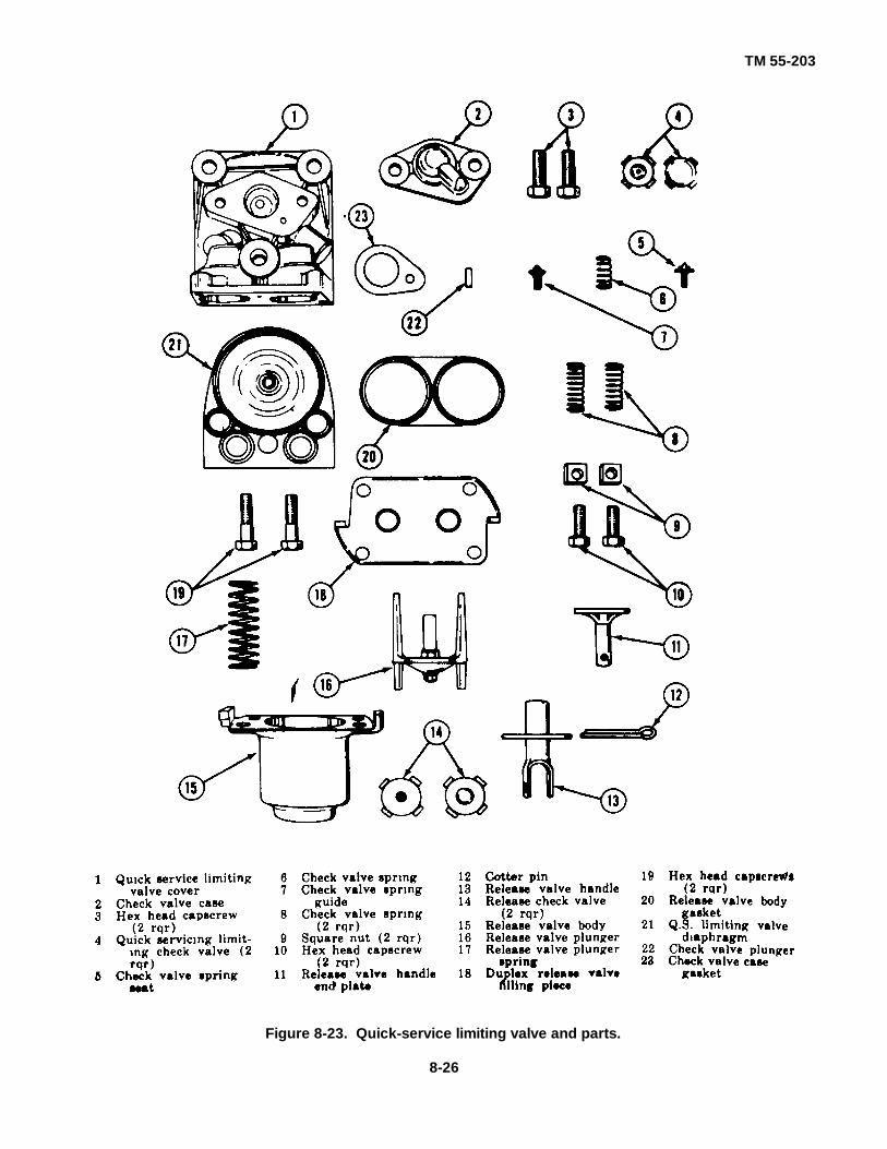
TM 55-203
Figure 8-23. Quick-service limiting valve and parts.
8-26

TM 55-203
to prevent oil leakage. Make sure the oil plug makes aseal between the flanged collar and the vearing surfaceon the piston to prevent oil leakage out of the chamber.Remove capscrew from oil plug, if used. To tighten oilplugs of the non-hexagon type, use a torque wrench andtighten to a force of 17 foot-pounds (200 inch-pounds).
(7) Inspection and lubrication of early type self-oiling piston
(a) The early vintage type self-oiling pistonhas two holes drilled in the piston head near the top ofthe piston. The piston must not be submerged incleaning fluid. To clean the ring and its groove, squirtthe cleaning fluid around the ring and then move thering around in its groove. Repeat the operation until thering and groove are thoroughly clean. After cleaning,blow the excess fluid away with a jet of air.
(b) If it is necessary to remove the ringfrom the piston ((6) above), remove the wick in thebottom of the groove. Do not replace when a new ringis applied.
(c) Follow the same procedure for filling theoil reservoir as described in (6) above.
(8) Inspection and lubrication of release-insuringparts. Inspect the release-insuring parts (fig 8-21) fordefects Reseat valve and seat if necessary Test springfor proper tension using a spring gage Apply new springif required.
(9) Inspection and lubrication of quick-servicelimiting valve and duplex release valve parts
(a) Inspect the quick-service limiting checkvalves and release check valves and seats for pitting.Renew if found defective. Lubricate the rubber checkvalves by placing them in a box with dry graphite.Shake the box and remove check valves, wipe offexcess graphite with a chamois.
(b) Lubricate the two short prongs of theduplex release valve plunger that fit in the bottom of thereservoir. Release valve body with brake cylinderlubricant prior to assembly to the body.
(10) Assembly of parts to service portionbody
(a) Press the side of the piston ringopposite the scarf to the bottom of the ring groove andapply three drops of lubricating oil through the ring scarfopening. Restore the ring to normal position andcarefully rotate ring in groove to distribute the oil.Position the ring scarf approximately 1 inch on eitherside of the piston top center.
(b) Apply a few drops of oil to pistonbushing and distribute evenly over the entire surface.Evenly distribute one drop of oil on the collar at thepiston spring end of the piston. Then insert the pistonand slide valve in the body, ,leaving them in releaseposition.
(c) Assemble balance in parts in reverseorder of removal, using new parts as required.
(11) Performance of code of tests. Installreconditioned valve portion on test rack and refer to TM55-21023 for testing instructions.
c. Emergency Portion(1) Choke fittings. The emergency portion
contains six choke fittings; figure 8-24 illustrates thelocation of these choke fittings. The instructions forcleaning and checking choke fittings in the serviceportion apply for all of these chokes except for chokes(1'), (3), and (4) which are not readily removable andshould be cleaned in place. The removable chokes (2),(5), and (6) must be removed, cleaned, and replacedone at a time. Remove the filter felt in choke (5), clean,and replace or renew if damaged. If choke (5) is theearlier type which does not have a filter felt, replace withthe latest design.
(a) Choke (3), which serves to protectagainst excessive spillover check valve leakage, islocated in the bushing under the spillover ball check (11,fig 8-25). Orifice size 3/64-inch drill.
(b) Choke (4) (fig 8-24), which serves toprotect against diaphragm leakage, is located an the ballcheck cover in the port between the chamber above thespiliover valves and the chamber above the strutdiaphragm. Orifice size No. 69 drill.
(c) Choke (1), which serves to control therate of quick-action chamber pressure reduction duringan emergency application, is located in the vent piston.Orifice size No. 69 drill.
(d) Choke (6), which controls the secondstage flow of air to the brake cylinder immediately afterthe incite valves closes during an emergencyapplication, is located in the emergency portion bodyand is accessible by removing a 1/4inch pipe plug.Orifice size 3/32-inch drill.
(e) Choke (5), which controls thequickaction chamber charging rate, is located in theemergency portion body under the ball check cover.The attached filter felt prevents restriction of the chokeby very fine dirt, thereby insuring the proper chargingrate of the quick-action chamber. Orifice size No. 73drill.
8-27

TM 55-203
(f) Choke (2), which controls the third stageof brake cylinder pressure buildup during emergencyapplication, is located under the emergency portioncover in the port which bypasses choke (6) when thetiming valve opens. Orifice size 9/64-inch drill.
(2) Springs. The emergency portion contains atotal of nine wire springs which are identified on figure 8-25 as follows:
(a) Accelerated release check valve spring5, holds the check valve (4) to its seat.
(b) Spillover check valve spring 6, holdscheck valve (8) to its seat.
(c) Diaphragm spring 7, holds the slidevalve to its seat when the diaphragm is balanced.
(d) Vent valve spring 20, holds theemergency vent valve to its seat.
(e) Inshot check valve spring 25, holds thecheck valve in contact with inshot piston stem
(f) Emergency piston spring 28, resistsmovement of the spring guide in the piston stem.
(g) Return sprang 31, returns the piston andslide valve to normal release position when brake pipeand quick-action chamber pressures are equalized.
(h) Graduating valve spring 34, holds thegraduating valve to its seat on the slide valve.
(i) Inshot piston spring 48 resists inshotpiston movement until brake cylinder pressure rises to15 pounds.
Figure 8-24. Location of the six emergency portionchoke fittings.
(j) Spring identification. The following tabulation givesthe Westinghouse Airbrake data necessary to identifyeach of the springs described.
Table 8-2. Spring Identification AB Emergency Portion
Approximate Approximate Approximate ApproximateReference No Part No 0. D. diameter wire free height No turns Material
5 A94952 3/4" .072" 1 13/32" 7 Ph Bronze6 A94581 3 1/64" .028" 1 3/32" 7 Ph Bronze7 A94839 11/16" .064" 1 1/8" 6 1/2 Ph Bronze
20 A81643 1 3/8" .121" 2 23/32" 71,/2 Steel25 A94836 33/64" .050" 1 23/32" 14 Ph Bronze28 A501006 13/16" .062" 2 13/32" 11 Steel31 A500944 1 27/32" .187" sq. 2 29/64" 6 Steel84 A93940 5/32" .020" 21/32" 12 Ph Bronze48 A95032 1 3/16" .098" 11/32" 8 Steel
(3) Inspection, lubrication, and assembly ofparts. Inspection, lubrication, and assembly of parts isthe same as that of the service portion with the followingexceptions:
(a) The main (emergency) piston cannot beremoved without first removing the ball check cover andtaking out the slide valve strut which holds the slidevalve to its seat. Damage will result if force is used toremove the emergency piston from its bushing withoutfirst removing the strut.
(b) The springs behind the vent valve andthe inshot valve are held in place by circular metalretainers which have lugs on two opposite sides.
These lugs engage under a lip around the outer edge ofthe cavities in the body casting. To remove the springand valve, press down on spring retainer and tilt it sothat one lug is exposed upward. When in this position,the parts can be readily removed and can bereassembled by using the same method in reverse.
(c) If the vent protector chamfer at theexhaust of the emergency portion body is pittedexcessively due to rust, refinish the surface with emerycloth or a suitable reamer. Do not remove
8-28
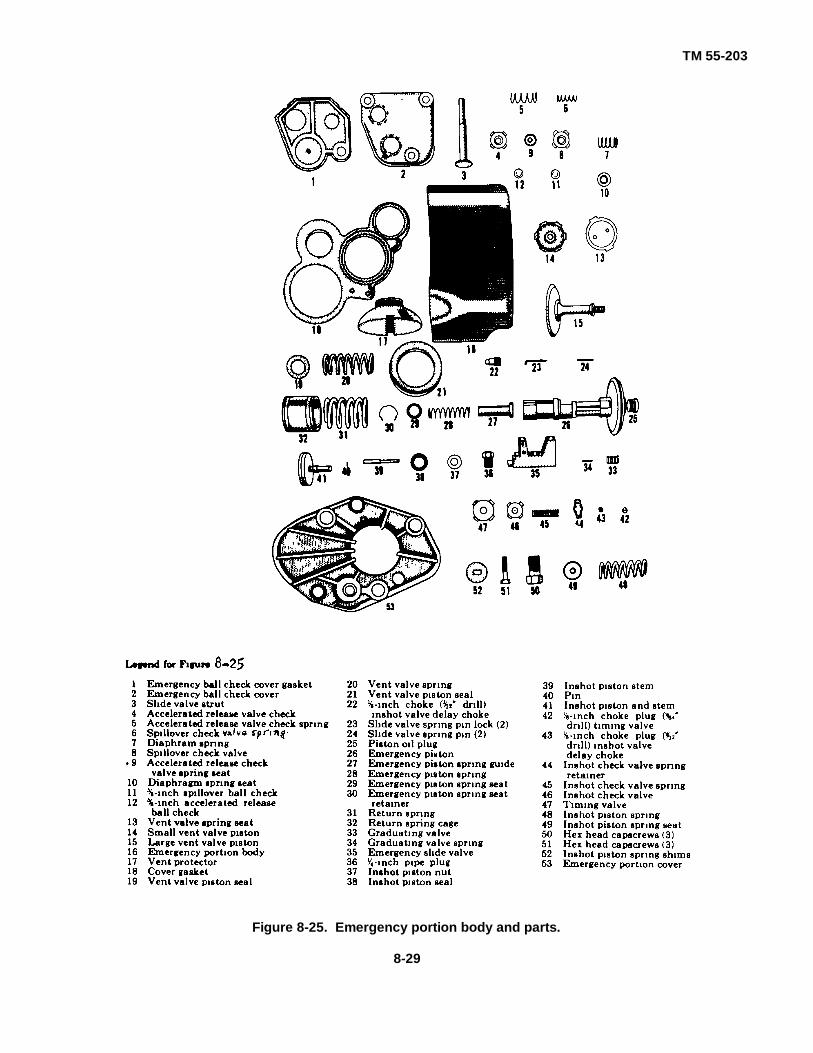
TM 55-203
Figure 8-25. Emergency portion body and parts.
8-29

TM 55-203
any more material than is necessary to obtain a cleansurface The chamfer must be held to a 45° angle toinsure proper fit and tightness of vent protector.
(d) When the vent valve piston and theinshot valve piston are assembled to the body, placetwo drops of oil in the piston ring groove. Rotate the ringin the groove to distribute the oil. Insert the piston in thebody and then evenly spread three drops of oil aroundthe piston bush. Move the piston back and forth severaltimes and then remove the surplus oil from the outeredge of the cylinder.
(4) Performance of code of tests. Installreconditioned valve portion on test rack and performcode of tests in accordance with instructions in TM 55-2006.
8-16. Shop Maintenance of AB-1-B Control Valve
a. General. Maintenance of the AB-1-B Con-trol Valve is the same as the AB Control Valve(para 8-15), except for the addition of a fillingpiece with selector valve portion, located betweenthe emergency portion and the pipe bracket.
b. Disassembly. Refer to figure 8-26, and dis-assemble the parts as illustrated. Use extremecare when dismantling the parts to avoid mutila-tion or damage to springs, gaskets, diaphragms,seals, and like items.
c. Cleaning and Inspection(1) Wash all parts in a suitable solvent that will
remove oil and grease. Do not allow gaskets andrubber-seated valves to soak in the cleaning fluid.
(2) Inspect valves and valve seats for wearpitting or scoring. Recondition or renew as required.
(3) Check springs for rust pits, distortion,breaks, cracks, and permanent set. The springs shouldhave a free height of 1 1/2 inches
.
(4) Replace all gaskets and diaphragms thathave broken or flattened beads, cracks, swelling, or cutson diaphragm sealing surfaces. Coat all gaskets anddiaphragms with dry graphite before replacing.
(5) Inspect wasp excluder for defects. Cleanwire mesh with compressed air. Renew if founddefective.
d. Reassembly. Refer to figure 8-26, andreassemble the parts as illustrated. Tighten nuts andcapscrews evenly, but not excessively to causedistortion of covers and gaskets.
8-17. Shop Maintenance of A-2-A Quick-ServiceValve
a. General(1) The A-2-A quick-service valve consists of a
pipe bracket and valve portion. The brake pipe strainerused in the pipe bracket is identical to the strainer usedin AB control valve pipe bracket.
(2) Three springs and one choke are used inthe valve portion. They are identified in figure 8-27 byreference numbers as follows:
(a) Choke (3) with filter controls thecharging of the quick-service volume reservoir. It islocated in the valve portion body under the strutdiaphragm cover. Attached to the choke plug is a filterfelt which prevents restriction of the choke by very finedirt, thereby insuring the proper charging rate of thequick-service volume reservoir. Orifice size No. 73drill.
(b) Spring (11) holds the piston slide valveto its seat.
(c) Check valve spring (10) seats the cutoffvalve check valve.
(d) Diaphragm follower spring (8) seats thediaphragm follower.
(e) The following tabulation gives the datanecessary to identify each of the springs described.
Table 8-3. Spring Identification A-2-A Quick-Service Valve
Approximate Approximate Approximate ApproximateReference No. Part No . O. D. diameter wire free height. No turns Material
11 A94839 11/16" .065" 1 1/8" 6 1/2 Ph Bronze10 A513914 11/16" .072" 1 1/16" 8 Steel8 A513913 1 5/32" .072" 1 15/16" 7 Steel
b. Disassembly(1) Remove nuts (24) (fig 8-27) from strut
diaphragm cover (22) and remove cover.(2) Remove slide valve strut (23), piston (14),
and slide valve (16). The remaining operating portions
can now be readily removed from the valve body. Takecare to avoid distortion or damage to parts with respectto piston springs, gaskets, diaphragms, slide valve, andlike items.
8-30

TM 55-203
Figure 8-26. Filling piece and selector valve portion.
c. Cleaning. Wash all metal parts in approvedsolvent that will dissolve oil and grease withoutabrasion. Dip all gaskets and rubber seated parts inapproved solvent to assist in removal of grease and dirtand immediately wipe dry after cleaning. Do not soakthe parts in the cleaning fluid. Blow out all air passageswith compressed air.
d. Inspection and Maintenance(1) Replace all gaskets which have broken or
flattened beads or any that reveal cracks or cuts ondiaphragm or sealing surfaces. Brush serviceablegaskets with a soft bristle brush (such as a shoe brush)
to remove any remaining dirt and to give them a polish.(2) Check the piston bushing for ring size by
using a cylinder gage.(3) Remove the filter felt in choke (3). Clean
and replace or renew if damaged. If the choke is theearlier type which does not have a filter felt, replace withthe latest design.
(4) Reconditioning of the slide valve and pistonis the same as for the AB control valve (para 8-15b(4)and (6)).
8-31

TM 55-203
(5) Inspect springs (8), (10), and (11) for rustpits, distortion, breaks, cracks, or permanent set.Renew all springs that are defective.
e. Assembly of Parts to Body(1) Press the side of piston ring opposite the
scarf to the bottom of the ring groove. Apply threedrops of lubricating oil through the ring scarf opening.Restore the ring to normal position and rotate ring ingroove to distribute the oil. Position the ring scarfapproximately 1 inch on either side of piston top center.
(2) Apply a few drops of lubricating oil to pistonbushing and distribute evenly over the entire surface.Distribute one drop of oil on the collar at the pistonspring end of piston, then insert piston and slide valve inthe body.
(3) Assemble balance of parts in reverse ofremoval, using new parts as required.
f. Performance of Code of Tests. Installreconditioned valve on test rack and perform code oftests in accordance with TM 552023.
8-18. Shop Maintenance of AB Brake Cylinder
a. Disassembly(1) Remove shipping cap and place piston
assembly on a clean workbench.(2) Remove packing cup (4) (fig 8-28) with a
wood tool about I inch wide and 1/8 inch thick, withrounded edges to prevent damage to packing cup andpiston lubricator.
(3) Place piston and nonpressure head in aholding fixture which will hold the compression springpartially compressed.
(4) Remove collar from end of hollow rod(3), then remove retaining plate and packing
seal (13).(5) Remove nonpressure head and
compression spring (9) from the hollow rod.
Figure 8-27. Assembly view of A-2-A qutck-serice valve.
8-32

TM 55-203
Figure 8-28. AB brake cylinder, showing air pipe connection when used with automatic slack adjuster.
b. Cleaning, Inspection, and Maintenance(1) Blow all dirt out of the nonpressure head
and strainer.(2) Using a scraper and solvent, clean the seal
recess in the nonpressure head gasket face.(3) With a tile, break any sharp edges from the
ends of the opening in the nonpressure head 'whichguides the hollow rod.
(4) Clean the piston and the hollow rod,removing any rust or rough surfaces; use emery cloth ifnecessary.
(5) Examine the compression spring. If rust,spots are found, clean them with emery cloth and coatthe spring with a rust preventive.
(6) Clean the seal ring retaining plate and theseal rings, renewing any ring which does not close firmlyon the hollow rod.
(7) Thoroughly clean the packing cup (4) withsolvent and clean the piston lubricator as follows:
(a) Submerge the piston lubricator in a tankof solvent for a few minutes; then loosen the lubricatorswab in its groove with a thin round edge blade. Returnthe lubricator swab to the solvent tank long enough todissolve the grease.
(b) Brush the outer surface of the lubricatorswab with a handbrush and blow dry with compressedair.
(c) Renew the lubricator swab if it is,damaged, worn out, or in such a condition that it cannotbe loosened and raised in its groove to make a fullcontact against the cylinder wall.
(d) Submerge the clean lubricator in a tankof oil. Soak in the oil for at least 10 minutes and allow itto drain for about 10 minutes This will saturate thelubricator swab with oil and thereby prevent it fromabsorbing the brake cylinder lubricant.
8-33

TM 55-203
c. Reassembly(1) Apply a light coat of brake cylinder lubricant
to the hollow rod and place the piston and hollow rod ina holding fixture. Then apply the compression spring (9)and nonpressure head (12) Use the locking mechanismof the fixture to hold the compression spring partlycompressed.
(2) Place the hollow rod lubricator swab overthe hollow rod and push into the recess in thenonpressure head. Put the swab compression ring -onthe inner portion of the assembly tool; then slide the toolover the outer end of the hollow rod until it contacts thelubricator swab. With the tool held in this position, pushfirmly on the outer portion forcing the swab compressionring off the tool into position around the lubricator swab.Insert brake cylinder lubricant in the nonpressure headrecess until the space is about 1/3 full. Place the swabretainer over the lubricator swab; then assemble theseal rings with their openings staggered. Completely fillthe recess with brake cylinder lubricant and apply theseal ring retaining plate. Fasten it with capscrewssecured with lockwashers.
(3) Apply the piston, lubricator (7) to piston withflat (felt) side next to piston. Apply the packing cup (4)to piston by starting the cup over the edge of piston;while holding it in this position, work the cup into placewith the hands. If the cup does not seat properlybecause of trapped air, the air can be removed byraising one side of the cup and pushing the cup intoplace with the hands.
(4) Apply shipping cap over the assembledpiston and secure with bolts to nonpressure head.
8-19. Shop Maintenance of Engine Portion ofAutomatic Slack Adjuster
a. Disassembly of Engine Portion(1) Remove snap ring (31) (fig 8-29) at end of
the ratchet nut bearing. Then remove the ratchetassembly from the adjuster body end of the casing (27).
(2) Remove check pawl ring (34), pawls (28),pins (29), and springs (30).
(3) Remove ratchet nut felt (11) at the end ofratchet nut bushing (33).
(4) Remove piston packing cup (21) by using awooden tool with rounded edges about 1 inch wide and3/32-inch thick, to prevent damage to packing cup andpiston lubricator swab (18) and retainer (20).
(5) Remove the lubricator swab (18) andretainer (20).
b. Cleaning, Inspection, and Maintenance(1) Thoroughly clean all parts in solvent to
remove oil, grease, and dirt.(2) Renew all worn or damaged parts.(3) Clean the piston lubricator swab and
retainer as follows:(a) Submerge the assembly in a tank of
solvent for a few minutes. Then loosen the lubricatorswab in its groove with a thin round-edge blade. Returnto solvent tank to dissolve the grease from the swab.Brush the outer surface of the swab with a handbrush toaid in removing the old grease. After the swab isthoroughly clean, dry with low pressure air.
(b) Renew the lubricator swab when it isworn, damaged, or in such condition that it cannot beloosened and raised in its groove to make full contactwith the cylinder.
(c) Submerge the cleaned piston lubricatorin a tank of new journal box oil for at least 10 minutes.Then allow the assembly to drain for about 10 minutes.This saturates the swab and prevents absorption of oilfrom the brake cylinder lubricant.
c. Reassembly of Engine Portion(1) Lubricate the cylinder wall and piston
packing cup (21) with brake cylinder lubricant.(2) Place the piston spring (26) in the pocket of
the casing (27). Place the piston (22) on top of thespring and apply the cylinder to the piston over thepacking cup.
(3) Apply pressure to force the cylinder intoplace against the resistance of the piston spring. Beforepressure is applied and during application of pressure,hold the knockout lug away from contact with pawl stop(25) to prevent rupture of this part. The knockout lug ispart of pawl (14) which is accessible through theadjuster body opening in casing (27). The pawl can bereached by removing pipe plug (15).
(4) Stand the ratchet assembly on the brass nutend and reassemble the pawl ring, pawls, pins, andsprings on the ratchet nut. Lubricate these parts and theratchet nut bearing with 6 ounces of graphite grease.
(5) Lower the casing (complete with piston andspring) in position over the ratchet nut.
Saturate the ratchet nut felt (11) with journal oil and putin place next to the ratchet nut bushing (33). If the felt isso worn that it does not seal against the ratchet nut,renew the felt.
(6) Replace felt retainer (32) and snapring (31).(7) Protect reconditioned engine portions againstdamage and entrance of dust and dirt during storage.
8-34

TM 55-203
Figure 8-29. Slack adjuster, automatic type, assembly view.
Section V. SINGLE-CAPACITY FREIGHT CAR 'BRAKE EQUIPMENT (K)
8-20. Features
a. General. The type K triple valve illustrated anddescribed in this manual, formerly standard for thesingle cylinder form of freight car brake equipment,possesses the features of quick action, quick service,uniform release, and uniform recharge. The K brakeequipment has been replaced in CONUS by the AB typeand is no longer accepted in interchange service by US
railroads. However, much US Army-owned rolling stockused within CONUS installations and in oversea areas isequipped with K brake equipment, so its features arediscussed herein for the information of TRSmaintenance personnel who may be unfamiliar with thistype of freight car brake.
8-35
TM 55-203
b. Quick-Action Feature. This functions when aemergency rate of brake pipe reduction takes placefrom any cause. This feature insures a quick drop ofbrake pipe pressure (by opening direct communicationbetween the brake pipe and the brake cylinder) at thetriple valve which in turn causes the next triple valve tofunction in the same manner, thereby propagating theemergency rate of brake pipe reduction and securingmaximum brake cylinder pressure through the entiretrain at a fast rate.
c. Quick-Service Feature. This feature producesuniform and quick application of the brakes in serviceapplications on long trains and reduces shocks. Thereare two service positions of the triple valve ports, quickservice and full service. When the valve is in quick-service position, the usual service port is only partiallyopen and in addition the quick-service ports are inregistration so that air is vented from the brake pipe intothe brake cylinder, which hastens the transmission ofthe reduction through a train. When the parts are in full-service position, the service port is fully open and thequick-service ports do not register. The proper positionis automatically assumed by the triple valve. On shorttrains the brake pipe pressure will fall more rapidly for acertain reduction at the brake valve than on long trains.Consequently, when the train is long the triple valveports will be stopped in quick-service position, as thepartial opening of the service port will permit theauxiliary reservoir pressure to fall as rapidly as thebrake pipe pressure is reducing. But when the train isshort, the triple valve ports will move directly to fullservice position as the rate of reduction is such that thefull opening of the service port is necessary in order thatthe auxiliary reservoir pressure may keep pace with thatin the brake pipe.
d. Uniform Release Feature. This brings aboutuniform release of the brakes on long trains and,lessens the possibility of shocks during the releaseoperation. A spring is placed on the auxiliary reservoirend of the triple valve with a projecting stem whichstops the triple valve slide valve in what is called fullrelease position, unless the pressure in, the brake pipeis raised materially higher than that of the auxiliaryreservoir. When the pressure in the brake pipe is in-creased about 3 pounds above that of the auxiliaryreservoir, the spring is compressed and the slide valveconsequently makes a further inward travel to retardedrelease position, partially closing the exhaust port andthereby making the release of brake cylinder pressureslower than before. In a 50-car train or longer, it isimpossible to raise the brake pipe pressure 3 poundshigher than the auxiliary reservoir for more than 30 carsback in the train; therefore, the brake cylinder exhaust is
retarded only on the first 30 cars, those beyondreleasing at the normal rate; but as those at the headend commence to release first and those at the rear endlast, the result is a practically uniform release on thetrain as a whole.
e. Uniform Recharge Feature. This feature insuresthat the recharge will be nearly uniform throughout along train, so that the tendency of the head brakes toreapply is reduced when the brake valve is returned torunning position, and a more nearly uniformreapplication short after a release is possible. Thisuniform recharge is brought about by decreasing thesize of the charging port or grooves when the triplevalve is in retarded release position (the piston sealingagainst the slide valve bush, except at one point wherethere is a feed groove smaller than that in the pistonbush), and as this can only be when the pressure in thebrake pipe is higher than that in the auxiliary reservoir, itis seen that where the pressure is the highest thecharging ports ,are the smallest, while where thepressure is the lowest, as at the rear end, the chargingports are the largest; thus, the recharge is more uniformbecause the high pressure will charge as quickly througha small port as the low pressure will through a large port.
8-21. Equipment Parts
a. General Following is a list of the parts whichmake up the single capacity K freight car brakeequipment, with a short description of each. These parts(fig 8-30) are discussed in detail in subsequentparagraphs.
b Triple Valve Type K. This has connectionsthrough its seat on the auxiliary reservoir to the brakecylinder and the auxiliary reservoir, and a pipeconnection to the brake pipe branch pipe. It operates inresponse to a suitable increase or decrease in brakepipe pressure, so as to charge the auxiliary reservoir byopening communication to it from the brake pipe; applythe brakes in service, by allowing the compressed airstored in the auxiliary reservoir to flow into the brakecylinder; and release the brakes, by allowing the lair inthe brake cylinder to escape to the atmosphere.
c. Brake Cylinder. This has a piston and rod isconnected through the brake levers and rods to thebrakeshoes that when the piston is forced
8-36
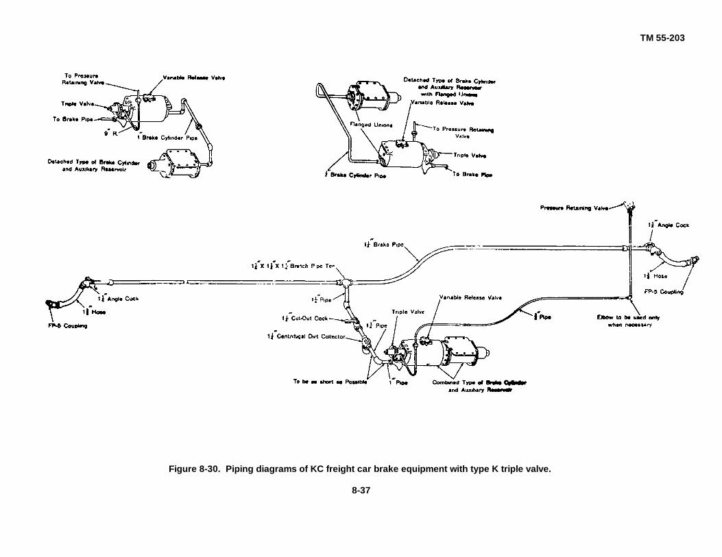
TM 55-203
Figure 8-30. Piping diagrams of KC freight car brake equipment with type K triple valve.
8-37

TM 55-203
outward by air pressure, this force is transmitted throughthe rods and levers to the brakeshoes and applies themto the wheels.
d. Auxiliary Reservoir. This contains stored air foruse in applying the brakes.e. Centrifugal Dirt Collector. This is connected in thebranch pipe between the brake pipe (and the triple valveas near the triple valve as circumstances will permit,and is for the purpose of preventing pipe scale, sand,cinders, or foreign particles of any kind from reachingthe triple valve.
f. Branch Pipe Tee. This tee is to prevent thedeposit in the branch pipe of excessive moisture fromthe brake pipe.
g. Pressure Retaining Valve. This valve isconnected by piping to the triple valve exhaust, itspurpose being when the handle is placed in retainingposition, to retard the rate of brake cylinder exhaustwhile the engineman is recharging the auxiliaryreservoirs and when brake cylinder pressure has beenreduced to a certain predetermined amount, to retainthat pressure in the brake cylinder.
h. Release Valve. This is attached to the auxiliaryreservoir, by means of which the brake may be releasedwhen desired by bleeding the reservoir.
i. Cutout Cock, Angle Cocks, Hose, and HoseCouplings. The location and uses of these items will bereadily understood from the isometric view of theequipment, figure 8-30 and the descriptions whichfollow.
8-22. Description of Parts
a. Triple Valve. The type K triple valve ismanufactured in two sizes, the K-1 for use with 6-inchand 8-inch freight car brake cylinders, corresponding tothe J-1 (F36), and the K-2 with 10-inch freight car brakecylinders, corresponding to the H-2 (H49). The K-1 willbolt to the same reservoir as the H-1 and K-2 to thesame reservoir as the H-2. Figures 8-31 and 8-32 aresectional views of the K-1 and K-2 types, respectively.Each valve is marked with its designation on the side ofthe valve body, and the K-2 may be distinguished fromthe K-1 by the fact that it has three, as compared withtwo, bolt holes in the reservoir flange. Also, in order todistinguish the type K valves from the old standard type,their exterior being similar when they are attached to theauxiliary reservoir, a lug is cast on the top of the valvebody, as shown in the illustrations. This enables them tobe easily recognized.
b. Port Connections, etc.(1) Openings. As shown in figures 8-31 and 8-
32, the retarding device body projects into the auxiliaryreservoir and is constructed so that free communicationexists between the auxiliary reservoir and chamber R, inwhich the slide valve 3, and graduating valve 7, operateThe opening marked "To Brake Cylinder," figures 8-31and 8-32, comes opposite one end of the tube whichleads through the auxiliary reservoir to the brakecylinder, when the valve is bolted in place on the end ofthe auxiliary reservoir, as shown in section in thediagrammatic views. The letter designating the portsand passageways, and the reference numbersdesignating the parts appearing in the illustrations,correspond throughout.
(2) Port designations. As illustrated in theisometric view of the slide valve seat, figure 8-33, theports are as follows:
(a) r leads to the brake cylinder and alsoconnects with chamber X over the emergency valve andunder the emergency piston.
(b) y leads to the check valve case andchamber Y.
(c) t leads to the top of the emergencypiston.
(d) p leads to the exhaust (or retainingvalve).
(e) Ports o on top and bottom of slide valveconnect and are alike in size. Port q runs directlythrough the slide valve, but is smaller at the top than atthe face of the valve, and the smaller port is out ofcenter with the larger port. Ports s and z run through thevalve and connect with cavities in the face, port z alsohas a cavity at the top.
(f) The face view of the graduating valveshows that it has a small cavity v. This valve is of theslide valve type, and it seats on the top of the slidevalve, where it controls the upper end of ports z, q ando. The purpose of the cavity v is to connect the upperends of ports o and q in a service application, asexplained in detail later.
(g) As shown by the face view of the slidevalve, n is a long cavity connected by a restricted port toa "tail port" at its right-hand end. This cavity n connectsthe ports through which the air escapes from the brakecylinder in releasing. Port b is cut diagonally from theface of the valve till it just cuts into the edge, at the topof the slide valve. It admits auxiliary reservoir pressureto port t in an emergency application.
8-38

TM 55-203
Figure 8-31. K-1 triple valve, actual section and end viewc. Brake Cylinder and Reservoir
(1) Auxiliary reservoir. A standard castironauxiliary reservoir is included with the complete freightbrake set, which is furnished either combined with thebrake cylinder (type KC, see fig 8-34), or detachedtherefrom, as desired, according to the conditions of theinstallation. This reservoir is of such volume that withan initial auxiliary reservoir pressure of 70 pounds andstandard (8-inch) piston travel, the brake cylinder andauxiliary reservoir pressures will equalize at 50 pounds.
(2) Piston. The piston 3 of the brake cylinderhas a hollow sleeve in which is the loose push rodattached to the levers and rods of the foundation brakerigging; 9 is a release spring which forces piston 3 torelease position when the air is exhausted from theopposite end of the cylinder; the packing cup pressesagainst the cylinder wall and prevents the escape of airpast the piston. In the combined equipment theauxiliary reservoir forms the pressure head for the brakecylinder; in the detached equipment, 18 is the pressure
head. Excessive piston travel will result in damage tothe protector 20 (if used) and must not be permitted.
d. Wabcotite Fittings
(1) Purpose. The purpose of the Wabcotitefittings is to produce pipe joints which can be made andmaintained permanently airtight and at the same timeavoid costly failures in road service due to the breakageof pipe or fittings. The fitting is designed to clamp thepipe back of the threaded end so as to relieve the threadof tension stresses, and it is arranged so that removalsand reapplications can be conveniently made.
(2) Fittting arrangement. The sectional view,figure 8-35, illustrates the construction details of theWabcotite fittings. Tightening the clamping nut willcause the anchor ring to close in and grip the pipe firmlyso that all bending
8-39

TM 55-203
Figure 8-32. K-2 triple valve, actual section and end view
strains are removed from its weakest point andconcentrated at its strongest point. The gasket is underan initial strain, but it is not subject to any subsequentmovement because the union flange is drawn up solid,metal to metal (fig 8-36).
e. Centrifugal Dirt Collector
(1) Location. The centrifugal dirt collector islocated in the branch pipe in order to protect the triplevalve against the entrance of pipe scale, sand, cinders,dirt, or foreign substances of any kind. Figure 837 is asectional view of the standard "Check Valve Type" inwhich the detachable enlarged dirt chamber and thecheck valve are the outstanding features. This designcomprises two separate portions; the upper or bodyportion to which the pipe connections are made, and thelower or dirt chamber portion which contains the brassumbrella-shaped check valve. The two portions arebolted together and the joint between is protected bymeans of a rubber gasket. The detachable dirt chamberprovides for easier cleaning, and the increased capacity
permits longer time between cleaning periods (may bethe same as for triple valve and brake cylinder).
(2) Check valve. The purpose of the checkvalve is to hold in the dirt chamber the collected dirtunder all conditions of airbrake operation. The bodyportion has a machined seat against which the checkvalve seats when a heavy reduction in pressure occursabove it, such as that during an emergency application,thereby shutting off communication between the dirtchamber and the dirt collector outlet. The check valveis so designed and placed on the valve stem as topermit a rocking motion whereby any fine dust whichmay collect on top of the check valve will be shaken offinto the dirt chamber.
f. Pressure Retaining Valve
(1) Description. The following description ofthe pressure retaining valve applies in detail
8-40
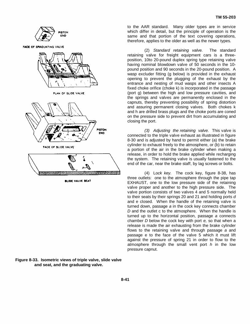
TM 55-203
Figure 8-33. Isometric views of triple valve, slide valveand seat, and the graduating valve.
to the AAR standard. Many older types are in servicewhich differ in detail, but the principle of operation is thesame and that portion of the text covering operations,therefore, applies to the older as well as the newer types.
(2) Standard retaining valve. The standardretaining valve for freight equipment cars is a three-position, 10to 20-pound duplex spring type retaining valvehaving nominal blowdown valve of 50 seconds in the 10-pound position and 90 seconds in the 20-pound position. Awasp excluder fitting (g below) is provided in the exhaustopening to prevent the plugging of the exhaust by theentrance and nesting of mud wasps and other insects Afixed choke orifice (choke k) is incorporated in the passage(port g) between the high and low pressure cavities, andthe springs and valves are permanently enclosed in thecapnuts, thereby preventing possibility of spring distortionand assuring permanent closing valves. Both chokes kand h are drilled brass plugs and the choke ports are conedon the pressure side to prevent dirt from accumulating andclosing the port.
(3) Adjusting the retaining valve. This valve isconnected to the triple valve exhaust as illustrated in figure8-30 and is adjusted by hand to permit either (a) the brakecylinder to exhaust freely to the atmosphere, or (b) to retaina portion of the air in the brake cylinder when making arelease, in order to hold the brake applied while rechargingthe system. The retaining valve is usually fastened to theend of the car, near the brake staff, by lag screws or bolts.
(4) Lock key. The cock key, figure 8-38, hasthree outlets: one to the atmosphere through the pipe tapEXHAUST, one to the low pressure side of the retainingvalve proper and another to the high pressure side. Thevalve portion consists of two valves 4 and 5 normally heldto their seats by their springs 20 and 21 and holding ports dand e closed. When the handle of the retaining valve isturned down, passage a in the cock key connects chamberD and the outlet c to the atmosphere. When the handle isturned up to the horizontal position, passage a connectschamber D below the cock key with port e, so that when arelease is made the air exhausting from the brake cylinderflows to the retaining valve and through passage a andpassage e to the face of the valve 5 which it must liftagainst the pressure of spring 21 in order to flow to theatmosphere through the small vent port h in the lowpressure capnut.
8-41

TM 55-203
Figure 8-34. Sectional and end view 8 -by 12-inch freight brake cylinder and reservoir combined.
(5) Brake cylinder pressures. Spring 21 iscapable of retaining a pressure of 10 pounds in thebrake cylinder. As long as the pressure of the air fromthe brake cylinder is greater than this, valve 5 isunseated and the air exhausts to the atmospherethrough the vent port which, being ,small, makes therelease of the brake much slower than when theretaining valve is not used. When the pressure hasbeen reduced to 10 pounds, it is no longer able to holdvalve 5 off its seat and the valve then closes and theremaining 10 pounds is retained in the brake cylinderuntil the handle 5 is turned down. Failure of thepressure retaining valve to hold air in the brake cylindergenerally is due to a leak in the connecting pipe, afrequent seat of trouble being at the union; it may alsobe due to a leak in the brake cylinders or in the retainingvalve, but seldom in the latter. When it is desired toretain high pressure in the cylinder, the handle is placedin the intermediate position marked HP. In this position,passage a connects chamber D with port d so that theair pressure must lift valve 4 against the 10-pound valueof spring 20. The air then 'passes through choke g tovalve 5, which will be lifted from its seat against the 10-pound value of its spring 21, resulting in a pressure of10 pounds in the spring chamber over valve 4. With 10pounds air pressure plus 10 pounds spring pressureacting above valve 4, pressure of 20 pounds is requiredto unseat this valve. Consequently, 20 pounds airpressure will be retained in the brake cylinder. The airwhich is vented to atmosphere in this position passesvalve 4, through choke k, valve 5 and through choke h.In passing through both chokes k and h, the flow of air is
restricted so that release of the brake is slower than inlow pressure position.
g. Vent Protector and Improved Wasp Excluder forRetaining Valve. Figure 8-39 illustrates a standardretaining valve with a vent protector (26) and animproved wasp excluder (23). The vent protector ismolded Wabco and fits tightly over the low pressurecapnut to protect the small vent port against theentrance of moisture which may cause corrosion andconsequent restriction or stoppage of the port. Theimproved wasp excluder contains a flexible Wabco discwhich normally maintains a seal against the entrance ofwater and wasps, but flexes readily to permit freeexhaust of brake cylinder air through the retaining valveexhaust. The excluder is applied to the tapped exhaustopening by a hollow capscrew, having a cross portthrough which air passes to the excluder exhaust. Boththe vent protector and the wasp excluder are applicableto retaining valves in service.
h. Four-Position Release Control Retainer(1) Features. The four-position type of
release control retainer (fig 8-40), accepted as arecommended practice by the AAR and acceptable oncars in interchange service in CONUS has the samefeatures of the AAR standard retaining valve, plus afourth position which affords a slowdown release ofbrake cylinder pressure from 50 pounds to 10 pounds inapproximately 86 seconds. The purpose of thisadditional position is to provide a better control of slackin long freight trains during release of the brakes whilethe train is in motion, especially in cases where trainsare operated over rolling country. The use
8-42

TM 55-203
Figure 8-35. Wabcottie fitting as used on the brakecylinder and reservoir.
Figure 8-36. Wabcotite pipe union.
of this fourth or slow direct exhaust position avoids thenecessity for resetting a retaining valve en route, especiallyon adverse grades. This new design of pressure retainingvalve has many constructional features which areconsidered improvements over the former types. Thevalve is mounted upon a pipe bracket which is fastenedpermanently upon the car and to which the pipe connectionis made. This arrangement makes it possible to removethe valve for cleaning and repairs without interfering withthe piping. A strainer, similar in construction to the ABvalve brake pipe strainer, is located in the bracket forcleaning the air before it passes to the valves and chokeswithin the retainer. A wasp excluder, similar to theseparate unit now being furnished with the standardretaining valve is built into the retainer body casting. Itconsists of a flexible rubber diaphragm confined within abell-shaped housing. A Wabcotite fitting connects theretainer pipe to the retainer pipe bracket. This insuresagainst breakage of the pipe at this point. Provision ismade for attaching the device for testing the brakecylinder, retainer pipe, and retainer without removal fromthe car.
(2) Exhaust positions. The exhaust of brakecylinder air through the release control retainer in the four-handle positions is as follows:
(a) In direct position, handle 5 is turned downward tothe position marked EX. The triple valve exhaust isthrough strainer 25, chamber A, unrestricted passage g,and past wasp excluder 22 to atmosphere in unrestrictednormal manner.
Figure 8-37. Centrifugal dirt collector.(b) In high pressure position, handle 5 is turned to the
position marked HP, 45 degrees below horizontal. Thetriple valve exhaust is through strainer 25, chamber A, pastlow pressure valve 4, through intermediate choke b, pasthigh pressure 4a, through final choke t, passage s, drilledport x in cock key 6, and past wasp excluder 22 toatmosphere. The pressure retaining valve of each valve is10 pounds, and since the
8-43

TM 55-203
Figure 8-38. Diagrammatic views of standard pressure retaining valve.
valves are in series, they will close and retain 20 poundsbrake cylinder pressure. The blowdown time of thebrake cylinder from 50 pounds to 20 through chokes band t is approximately 90 seconds.
(c) In low pressure position, handle 5 is turned tothe horizontal position marked LP. The triple valveexhaust is through strainer 25, chamber A, past lowpressure valve 4, through choke b, chamber D, port g incock key 6, and past wasp excluder 22 to atmosphereValve 4 will close to retain 10 pounds pressure in thebrake cylinder. The blowdown time of the cylinder from50 pounds to 10 pounds through choke b isapproximately 60 seconds.
(d) In slow -direct exhaust position, handle 5 isturned to the position marked SD, 45 degrees abovehorizontal. The triple valve exhaust is through choke a,port g in cock key 6, and past wasp excluder 22 toatmosphere. The blowdown time of the brake cylinderfrom 50 pounds to 10 pounds is approximately 86seconds; however, brake cylinder exhaust continuesuntil all pressure is vented.
i. Variable Release Valve
(1) Valve. Figure 8-41 illustrates the auxiliaryreservoir release valve which is of the variable reductiontype with a maximum rate of reduction that permits therapid depletion of auxiliary reservoir pressure. Thisvalve is installed horizontally, providing greaterclearance than the vertical type valve; and the internal
parts are accessible for repair or replacement withoutremoving the complete device from the reservoir. Inorder to inspect the valve assembly and spring, it is onlynecessary to remove the valve stem nut.
(2) Handle. The handle is made in two partswhich are pivoted to impart travel to the variableopening vent valve, thereby unseating the latter,permitting the air to discharge from the reservoir. Theamount of travel of the variable opening vent valvedetermines the rate of blowdown. A light or short pull onthe hand rod results in a slow rate of discharge ofauxiliary reservoir air, whereas a heavier pull, movingthe valve to its maximum open position, will causeauxiliary reservoir pressure to be exhausted from 70pounds in approximately 3 seconds. This valve isoperated in the same manner as the old, by hand rodsfrom either side of the car, and being fitted with 1/2-inchpipe stud, is completely interchangeable with the old.
j. Angle Cock. Figures 8-30 and 8-45 illustrate theangle cock, one of which is installed at each end of thebrake pipe as shown. The cock is open with the handleparallel to the pipe line, as illustrated, and closed withthe handle crosswise or at right angles to the pipe line.The handle may be removed independent of the socket.After driving out the hinge pin, the handle may be easilyremoved by first depressing it and then sliding it forwardto permit the web to clear the
8-44

TM 55-203
Figure 8-39. Sectional view of retaining valve withvent protector and improved wasp excluder.
socket lugs. The handle, of course, locks in both open andclosed positions. When so locked, it is necessary toslightly raise the handle before it can be turned, thusinsuring against accidental opening or closing by beingstepped upon, flying missiles, or loose rods and chains. Anextension with a U-bolt groove to the brake pipe end of theangle cock serves to support the brake pipe entering theangle cock while the groove in the extension permits theangle cock to be positively attached to the hanger bracket.The hinge portion has been strengthened and the size ofthe hinge pin increased to provide a larger bearing area. Asplit type socket is used and the rivet pinhole for lockingthe socket to the key is drilled through the split portion,engaging a notched out cavity in the square of the key.These changes provide greater strength and closer fit ofthe hinge portion, and a close and permanent fit betweenthe 'handle socket and the cock key.
k Branch Pipe Tee. The purpose of the branch pipetee (fig 8-42) is to prevent moisture that may be depositedin the brake pipe, from any cause, draining into the branchpipe connection and from thence into the triple valve.While the centrifugal dirt collector has proved very efficientin collecting moisture and dirt from the piping
of the airbrake system, thereby protecting the triple valve,the use of the branch pipe tee will materially assist inpreventing the excessive deposit of moisture in the branchpipe sometimes occasioned in charging and testing drainsfrom poorly designed yard plants, or because thelocomotive has insufficient reservoir capacity or coolingpipe to insure precipitation of the water before passing tothe brake system. This fitting has the interior coring sodesigned that the outlet from the brake pipe to the branchpipe is at the top. Thus, as air enters at K from the brakepipe it flows upward into chamber L and thence through thepipe opening at the bottom to the branch pipe, the moistureand heavy particles of dirt passing on through the brakepipe.
l. Cutout Cock. The cutout cock, figure 8-43, ofwhich there is one, 1 1/4-inch size in the branch pipe,should be placed where it can easily be reached butprotected from accidental closing. This cock, when closed,cuts off communication between the brake pipe and thetriple valve. The handle should be in such a position that,as affected by vibration, it would tend to jar open instead ofshut.
m. Hose Connections. These (fig 8-44) makethe brake pipe continuous throughout the train. When carsare being separated, as in switching, the angle cocksshould be closed and the hose should be uncoupled byhand, to prevent rupture or damage. Failure to uncoupleby hand causes shifting and breaking of the brake pipe aswell as damage to the coupling gasket and hose.
8-23. Operation of Equipmenta. General. As it is impossible to show all the ports
and connecting passageways in the graduating valve, slidevalve, and seat by any single section taken through thetriple valve, figures 8-45 through 8-50 illustrate in a purelydiagrammatic way the relations of the various parts to eachother, for the different positions of the triple valve piston.The actual proportions and mechanical construction of theparts have been disregarded where necessary to make theconnections 'and operation more easily understood.
b. Full Release and Charging Position. As shown infigure 8-45, air from the brake pipe enters the triple valvethrough passages a and e, cylinder cap ports f and g tochamber H on the face of the triple valve piston; thencethrough feed groove i, now open to chamber R above theslide valve, which is always in free communication with theauxiliary reservoir. Air flows from
8-45

TM 55-203
Figure 8-40. Diagrammatic views of four-position release control retainer.
the brake pipe to the auxiliary reservoir, as described,until their pressures become equal, when the latter isthen, fully charged.
c. Quick-Service Position
(1) First action. A quick service application ofthe brake is obtained by making a gradual reduction inbrake pipe pressure. As soon as the pressure inchamber H has been sufficiently reduced below that inchamber R on the other side of the triple valve piston,
the higher pressure on the auxiliary reservoir side of thepiston is able to overcome the friction of the piston 4and its attached graduating valve 7 and move theseparts to the left until the shoulder on the end of thepiston stem strikes against the right-hand end of theslide valve 3. The latter is then moved to the left untilthe piston strikes the graduating stem 21, which is heldin place by the compression of graduating spring 22.The parts of the valve are then in the position shown infigure 8-46. The first movement of the piston 4 closesthe feed groove i, preventing air from feeding back intothe brake pipe from the auxiliary reservoir, and at thesame time the graduating valve opens the
8-46

TM 55-203
Figure 8-41. The auxiliary reservoir variable releasevalve.
Figure 8-42. Branch pipe tee.
Figure 8-43. Sectional view of cutout cock
Figure 8-44. Hose connection
(2) Secondary action. At the same time, thefirst movement of the graduating valve connects the twoports o and q in the slide valve through the cavity v in thegraduating valve, and the movement of the slide valvebrings port o to register with port y in the slide valve seat,and port q with port t. Consequently, the air in chamber Yflows through ports y, o, v, q and t, thence around theemergency piston 8, which fits loosely in its cylinder, tochamber X and the brake cylinder. When the pressure inchamber Y has reduced below the brake pipe pressureremaining in a, the check valve 15 is raised and allowsbrake pipe air to flow past the check valve and through theports mentioned above to the brake cylinders. The size ofthese ports is so proportioned that the flow of air from thebrake pipe to the top of emergency piston 8, is notsufficient to force the latter downward and thus cause anemergency application, but at the same time enough air istaken from the brake pipe to cause a definite localreduction in brake pipe pressure at that point, which istransmitted in like manner to the next ,triple valve and, inturn, to the next, thus increasing the rapidity with which thebrake pipe reduction travels through the train.
d. Full-Service Position. With short trains, the brakepipe volume being comparatively small, the pressure willreduce more rapidly for a certain reduction at the brakevalve than with long trains. Under such circumstances, itmight be expected that the added reduction at each triplevalve by the quick-service feature would bring about sorapid a brake pipe reduction as to cause quick action andan emergency application, when only a light applicationwas intended. (The emergency application is explainedlater. ) But this is automatically prevented by the triplevalve itself.From figure 8-46 it will be noted that in the quick-serviceposition, port z in the slide valve and port r in the seat donot fully register. Nevertheless, the opening is sufficient toallow the air to flow from the auxiliary reservoir to the brakecylinder with sufficient rapidity to reduce the pressure in theauxiliary reservoir as fast as the pressure is reducing in thebrake pipe, when the train is of considerable length. If thebrake pipe reduction is more rapid than that of the auxiliaryreservoir, which may be the case on short trains, thedifference in pressure on the two sides of piston 4 soonbecomes sufficient to slightly compress the graduatingspring, and move the slide valve
8-47

TM 55-203
Figure 8-45. Release and charging position.

TM 55-203
Figure 8-46. Quick service position.
to the position shown in figure 8-47, called Full Service.In this position, quick-service port y is closed, so that noair flows from the brake pipe to the brake cylinder.Thus, when the brake pipe reduction is sufficiently rapid,there is no need for the additional quick-servicereduction, and the triple valve automatically cuts out thisfeature of the valve when it is not required. Also, in full-service position ports z and r are fully open, allowing theauxiliary reservoir pressure to reduce more rapidly, soas to keep pace with the more rapid brake pipereduction.
e. Lap Position. When the brake pipe reductionceases, air continues to flow from the auxiliary reservoirthrough ports z and r to the brake cylinder, until thepressure in the chamber R becomes enough less thanthat of the brake pipe to cause piston 4 and graduating
valve 7 to move to the right until the shoulder on thepiston stem strikes the left-hand end of slide valve 3.As the friction of piston and graduating valve is muchless than that of the slide valve, the difference inpressure which will move the piston and graduatingvalve, will not be sufficient to move all three;consequently, the piston stops in the position shown infigure 8-48. This movement has caused the graduatingvalve to close z, thus cutting off any further flow of airfrom the auxiliary reservoir to the brake cylinder andalso port o, thus preventing further flow of air from thebrake pipe through the quick-service portsConsequently, no further change in air pressures canoccur, and this position is called Lap, because all ports
8-49

TM 55-203
are tape--that is, closed. Figure 848 shows the parts inquick-service lap position. It will be seen that the exactposition of the slide valve 3, in lap position dependsupon whether its previous position was that of quick-service, figure 846, or full service, figure 8-47. If theformer, the lap position assumed would be quick-servicelap position, as shown in figure 8-48. If the slide valvehad previously moved to full-service position, however,the lap position assumed would be full-service lapposition, figure 8-47, but with the graduating valvemoved back so as to blank ports z and o in the slidevalve and with the shoulder on the piston stem incontact with the ,left-hand end of slide valve 3 as shownin figure 8-48. If it is desired to make a heavier applica-tion, a further reduction of the brake pipe pressure ismade and the operation described above repeated until
the auxiliary reservoir and brake cylinder pressurebecome equal, after which any further brake pipereduction is only a waste of air. About 20 pounds brakepipe reduction will ,give this equalization, with 70pounds brake pipe pressure and 8-inch piston travel.
f. Retarded Release and Charging Position
(1) Auxiliary reset in pressure. The K triple valve hastwo release positions, full release and retarded release.Which position its parts will move to When the trainbrakes are released depends upon how the brake pipepressure is increased in relation to the auxiliary reservoirpres-
8-50

TM 55-203
Figure 8-48. Quick-service lap position .sure, as already explained. It is well known that infreight trains when the engineman releases the brakes,the rapidity with which the brake pipe pressure increaseson any car depends on the posi(tion of the car in thetrain. Those cars toward the front, receiving the air first,will have their brake pipe pressure raised more rapidlythan those in the rear. With the old standard apparatus,this is due to two things: the friction in the brake pipe;and the fact that the auxiliary reservoirs in the frontbegin to recharge, thus tending to reduce the pressurehead by absorbing a quantity of air and holding back theflow from front to rear of the train. The retarded-releasefeature of the type K triple valve overcomes the secondpoint mentioned, taking advantage of the first whiledoing so. The friction of the brake pipe causes the
pressure to build up more rapidly in chamber H of thetriple valves toward the front end of the train than inthose at the rear. As soon as the pressure is enoughgreater than the auxiliary reservoir pressure remainingin chamber R after the application as above described,to overcome the friction of piston, graduating valve, andslide valve, all three are moved toward the right until thepiston stem strikes the retarding stem 31. The latter isheld in position by the retarding spring 33. If the rate ofincrease of the brake pipe pressure is small as, forexample, when the car is near the rear of the train, it willbe impossible to raise the pressure in chamber H 3pounds higher than that in the auxiliary reser-
8-51

TM 55-203
Figure 8-49. Retarded release and recharging positions.
voir on account of the flow of air from chamber Hthrough feed groove i into the auxiliary reservoir, whichis going on at the same time, the triple valve parts willremain in this position, as shown in figure 8-45. Brakecylinder air is exhausted through port r, large cavity n inthe slide valve, and port p leading to the atmosphere (orretaining valve). The auxiliary reservoirs recharge asdescribed under "Full Release and Charging. " If,however, the triple valve is near the head of the train,and the brake pipe pressure builds up more rapidly thanthe auxiliary reservoir can recharge, the necessaryexcess of pressure in chamber H over that in theauxiliary reservoir will be attained quickly, and will causethe piston to compress retarding spring 33, and movethe triple valve parts to the position shown in figure 8-49.
(2) Retarded release. exhaust cavity n in theslide valve now connects port r leading to the brakecylinder with port p to the atmosphere, and the brake willrelease; but as the small "tail port" extension of cavity nis over exhaust port p, the discharge of air from thebrake cylinder to the atmosphere is quite slow. In thisway, the brakes on the front end of the train require alonger time to release than those on the rear. Thisfeature is called the "retarded release," and although thetriple valves near the locomotive commence to releasebefore those in the rear, yet the exhaust of air from thebrake cylinder in retarded release position is sufficientlyslow to hold back the release of the brakes at the frontend of the train long enough to insure a practicallysimultaneous release of the brakes on the train as awhole. This permits releasing the brakes on
8-52

TM 55-203
Figure 8-50. Emergency position.
very long trains at lower speeds without danger of asevere shock or break-in-two than is possible withoutthis feature.
(3) Triple valve piston feed groove. At thesame time, the back of the triple piston is in contact withthe end of the slide valve bush, and, as these twosurfaces are ground to an accurate fit, the piston makesa tight "seal" on the end of the bush except at one pointwhere a feed groove (not shown in the dlagrammatics)is cut in the piston to allow air to pass around the end ofthe slide valve bush into chamber R and the auxiliaryreservoir. This feed groove is much smaller than thestandard feed groove t in the piston bush, so that whenthe triple valve piston is in retarded release position, therecharge of the auxiliary reservoir takes place muchmore slowly than when it is in full-release position. This
feed groove is larger in the K-2 than In the K-1 triplevalve so as to maintain the proper rate of recharge totheir respective auxiliary reservoirs in retarded releaseposition.
g. Emergency Position. Quick action is caused bya sudden and considerable reduction in brake pipepressure below that in the auxiliary reservoir, no matterhow caused. This fall in brake pipe pressure causes thedifferences in pressure on the two sides of piston 4 toincrease very rapidly, so that by the time the piston hastraveled to its full-service position, as already explained,there is a sufficiently higher pressure on the auxiliaryreservoir side of the triple valve piston to cause it tocompress the graduating spring 22, forcing back thestem and spring until the
piston seats firmly against the gasket, as shown8-53

TM 55-203
in figure 8-50. The resulting movement of the slidevalve opens port t In the slide valve seat and allows airfrom the auxiliary reservoir to flow to the top ofemergency piston 8, forcing the latter downward andopening emergency valve 10.
The pressure in chamber Y being thereby instantlyrelieved, allows brake pipe air to raise the check valve15 and flow rapidly through the chambers Y and X to thebrake cylinder, until brake cylinder and brake pipepressures nearly equalize, when the valve is forced toits seat by the check valve spring, preventing thepressure in the cylinders from escaping back into thebrake pipe again. The emergency valve, being heldopen by the emergency piston, will consequently returnto its seat when the auxiliary reservoir and brakecylinder pressure have nearly equalized. At the sametime, port s in the slide valve registers with port r in theslide valve seat and allows air from the auxiliaryreservoir to flow to the brake cylinder. But the size ofports s and r is such that comparatively little air getsthrough them before the brake pipe has stopped ventingair into the brake cylinder. This sudden discharge ofbrake pipe air into the brake cylinder has the sameeffect on the next triple valve as would be caused by asimilar discharge of brake pipe air to the atmosphere. Inthis way ,each triple valve causes the next to assumeemergency position, thus giving a quick and fullapplication of all brakes.
The release after an emergency is effected in exactlythe same manner as after a service application, butrequires longer time, owing to the high brake cylinderand auxiliary pressures and lower brake pipe pressures.
8-24. Maintenance
a. General. The movable parts of the triple valveshould never be removed while it is on the car. If thevalve is not working properly or needs cleaning andoiling, take it down and replace it by a valve in goodcondition. All cleaning and oiling should be done at abench, by a competent mechanic, where the liability ofdamage to the internal parts of the valve is least. Anyattempt to take the triple valve apart while still on thecar is almost sure to result in a large percentage ofvalves being injured by careless handling or dirt gettinginside the pipes or valve. If repairs are necessary, suchtriple valves should be returned to the shops for thatpurpose.
b. Retaining Valve. The retaining valve shouldstand vertically; there should be no obstruction to theremoval of the caps; it should be so located as to befreely accessible when the train is in motion. It shouldbe cleaned, but not oiled, every time the remainder ofthe airbrake equipment receives that attention; both itand the connecting pipe should be well secured; and alittle flexibility should be provided in the pipe leading to
it from the triple valve. The wasp excluder (if used)should be removed from the retaining valve during theusual brake cleaning period and the retaining valve pipeblown out, after which the wasp excluder should bereplaced in the retaining valve.
c. Brake Cylinder Lubrication.
(1) Disassembly. Close the branch pipecutout cock and drain the auxiliary reservoir. Fasten thehollow piston rod and nonpressure head together with acotter pin through the hole provided in the hollow rod orwith a suitable clamp. Remove -the nuts fromnonpressure head bolts, then remove the piston fromthe cylinder.
(2) Cleaning cylinders. Scrape the oldlubricant from the cylinder wall and leakage groove andwipe these surfaces clean and dry. Kerosene may beused for assisting in cylinder cleaning but should becompletely removed to prevent damage to cylindergaskets and packing cups. If the cylinder wall is rusted,the rust should be removed with sandpaper.
(3) Cleaning piston and packing cup.Remove expander ring (if used) from piston Scrape oldlubricant from the metal part and packing cup, using adull-edge round-end scraper (like a case knife), andwipe all surfaces clean and dry. The packing cup shouldbe carefully examined and should be renewed if brittle,thin at any point, cut, cracked, or otherwise defective.Examine piston and follower plate for cracks and tightenup follower plate nuts.
(4) Applying new packing cups. Examinefollower studs for tightness in the piston. Locate thepacking cup centrally on the piston. Place the followerin position and apply the nuts, bringing them in contactwith the follower without tightening. Then draw themdown uniformly.
(5) Application of lubricant. Apply a coatingof brake cylinder lubricant to the wall of the cylinder andto the outside of the packing cup with a brush.
(6) Assembling. The piston should be stoodon end with the top edge or flat side of the nonpressurehead flange and the opening of the expander ring (ifused) toward the workman. With the piston In thisposition, enter it into the cylinder. The sleeve or rodshould then be slowly raised and the piston moved intothe cylinder until the upper portion of the packing cupengages
8-54

TM 55-203
the cylinder wall. Form this portion into the cylinderwhile the sleeve or rod is being gradually raised, takingspecial care not to crimp or otherwise damage thepacking cup Then pull upward and outward on thesleeve or rod until it is in horizontal position. Push thepiston to its release position and then raise the sleeve orrod to the top of the cylinder to determine whether theexpander (if used) is in its proper position, which will beindicated by freedom of movement.
d. Triple Valve Lubrication(1) Cleaning. Under ordinary service
conditions, the triple valve should be thoroughly cleanedand lubricated every 15 months. The proper interval isbest determined for each particular case by a carefulinspection and trial. Where conditions are severe andthe triple valve exposed to extremes of weather, dirt,etc, more frequent inspections will, no doubt, be foundnecessary. Where the valve is protected and notsubjected to hard usage,-the interval may belengthened. The piston, slide valve, graduating valve,and bushings must be thoroughly cleaned so as toremove all dirt, oil, gum, or grease. Benzine, gasoline,or other approved cleaning fluid can be used for thispurpose. The piston packing ring and its groove shouldbe cleaned without removing the ring from the pistongroove. This can be done by dipping the piston in thecleaning fluid and then moving the ring around in thegroove. This operation should be repeated until thegroove and ring are thoroughly cleaned, after which theexcess cleaning fluid can be blown away or dried byusing an air jet.
(2) Loosening rings. Where rings are stuckwith dirt too tightly to be moved in the groove, it may benecessary to soak the ring in penetrating oil and thentap the ring gently with a hard block. For this purpose, amaple or hickory wooden block about 1 by 1 by 4 inches(with square ends) should be used to tap the ring so asto drive it flush with the top edge of the groove. Thistapping should start at one side of the ring joint andprogress around the piston in short steps until the ring isloosened sufficiently to be moved in the groove. If thisprocedure will not loosen the ring, it is evident that thegroove is binding, in which case, the groove must be -coniditioned and a new ring fitted.
(3) Glazing valves. The face of thegraduating valve, the upper surface of the slide valve(which is the graduating valve seat), the slide valveface, the slide valve seat, and the upper portion of thebushing (slide valve spring bearing) must be glazed withthe best grade of very fine, pure, dry airbrake graphite.To apply the graphite, it will be found convenient to usea small wooden paddle about 8 inches long having asmall piece of chamois skin glued to the paddle end.
The width of this paddle must be somewhat less thanthe width of the slide valve seat in the bushing. Place asmall quantity of the graphite on the chamois skin andrub the surfaces specified until they show a dark coppercolor. There must be no free graphite allowed to remainon the valves or seats and they must be free from anyoil or grease before the graphite is applied.
(4) Oiling piston Before the cleaned piston isreplaced in the piston bushing, press the side of thepacking ring opposite the scarf to the bottom of itsgroove, then introduce three drops of approved triplevalve oil in the groove through the ring scarf opening,after which restore the ring to its normal position andcarefully rotate it in its groove to distribute the oil.Position the ring scarf approximately 1 inch either sideof the piston top center Next, place three drops of thetriple valve oil in the clean, dry bushing and distribute itover the entire surface in a manner to avoid introducingdirt or other grit. Then insert the piston and slide valvein the body, leaving them in release position, after whichplace three additional drops of tripe valve oil in thecylinder bushing and again distribute it on the bushingsurface as previously described. No lubricant should beused on the quick action parts.
8-25. General Information for Carmen and Trainmen
a. Releasing Brakes. In releasing an individualbrake by means of the release valve on the auxiliaryreservoir, the brake pipe being charged, the releasevalve should be held open only until the exhaust isheard to start. In this way, if the auxiliary reservoirpressure is reduced much below that ,in the brake pipe,the piston will go to retarded release position and therelease will be slower. Where there is no air in thebrake pipe, the brake must be released by holding therelease valve open until all the air has escaped. Whenit is found necessary to cut out the brake, close thecutout cock in the brake pipe branch pipe and bleed theauxiliary reservoir.
b. Road Troubles
(1) Common defects. The most seriousdefects that might cause trouble on the road are leakyslide valve, leaky check valve case gasket, leaky triplevalve body gasket, leaky emergency
8-55

TM 55-203valve, leaky main piston packing ring, leaky auxiliaryreservoir tube, and broken graduating spring.
(2) Air leaks(a) A blow from the triple valve exhaust indicates a
leak either from the brake pipe or the auxiliary reservoir.To determine which, cut out the brake by closing thebrake pipe branch pipe cutout cock. If the brake appliesand the blow stops, it indicates a leak from the brakepipe If the blow continues and the brake does not apply,it indicates a leak from the auxiliary reservoir.
(b) An auxiliary reservoir blow is caused by a leakyslide valve, triple valve body gasket, or the auxiliaryreservoir tube. A leaky slide valve usually will cause ablow when the triple valve is in either release orapplication position, while a leaky body gasket orauxiliary reservoir tube will cause a blow only when thetriple valve is in release position.
(c) A brake pipe blow is caused either by a leak bythe emergency valve or the check valve case gasket.
(d) A leaky main piston packing ring may preventthe brake from applying on a light reduction on a longtrain or if applied it may prevent a proper release.
(3) Broken springs
(a) A broken graduating spring may causeundesired quick action depending upon the condition of
the triple valve and the rate of brake pipe reduction. Ifthe triple valve is dry and gummy or the brake pipe isreduced at too rapid a rate through leakage orotherwise, quick action is almost sure to result.
(b) A broken retarding spring permits the triplevalve piston to move to retarded release position,causing a slow release of the brake.
c. Valve Buzzing. A type K triple valve in goodcondition will not continuously buzz. A continuouslybuzzing valve indicates that the emergency valve isleaking, in which case there will be a blow at the triplevalve exhaust. This may sometimes be remedied byjarring the triple valve lightly near the emergency valve.Should this not stop the blow, apply the brake inemergency by parting the hose and opening the anglecock quickly; then release the brake by connecting upthe hose and repeat the operation, if necessary. Thismay dislodge the dirt and allow the valve to seatproperly. If the valve cannot be forced to its seat, thedefect should be reported for correction.
Section VI. SPECIAL-PURPOSE EQUIPMENT
8-26. Air Strainer and Wasp Excluder
a. General. The 3/8-inch OB-1 strainer with choke and wasp excluder may be encountered on freight cars builtfor foreign service and other special-purpose cars. It isconnected with the triple valve exhaust by a short pipenipple and takes the place of the pressure retainingvalve and pipe described in paragraph 8-21g. Thepurpose of the device is to choke the brake cylinderexhaust and provide for a longer release time after arelease has been started. This device, however,exhausts all the air pressure at the reduced rate. Thestrainer curled hair cleans the air and protects the chokefrom being clogged. A wasp excluder located in thestrainer opening to the atmosphere insures a clearpassage.
b. Components. The 3/8-inch OB-1 air strainerwith choke and wasp excluder consists of a strainerbody tapped for a 3/8-inch pipe, perforated brass plate,curled hair which cleans the air, and a choke fittingwhich holds the choke and wasp excluder. The OB-1strainer is connected to the triple valve exhaust pipe bya cap, thus the path of the exhaust air is through thecap, strainer hair, choke, and wasp excluder to theatmosphere.
8-27. Combined Brake Cylinder and AuxiliaryReservoir
a. General. The auxiliary reservoir has a chokeplug inserted in the tube leading to the brake cylinder.The purpose of the choke is to nullify the quick-actionfeature. In other respects, this reservoir and the brakecylinder are the same as those described elsewhere inthis manual. Piston travel less than 7 inches or morethan 9 inches must be adjusted to approximately 8inches.
b. Operation. The operation of this equipment isthe same as that described in paragraph 8-16 exceptwhen the brake pipe pressure is suddenly reduced tocause emergency quick action, as described inparagraph 8-23g (fig 8-50). The choke then controls theflow of brake pipe air to the brake cylinder. It, therefore,prevents quick action from being passed to adjoiningequipment. Consequently, in a train of special-purposeequipment, the brake pipe reduction will not be at anemergency rate throughout the train on account
8-56
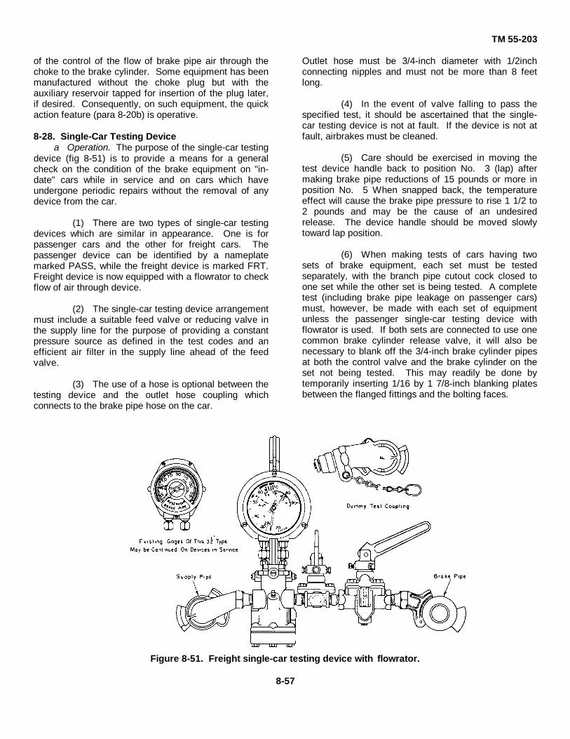
TM 55-203
of the control of the flow of brake pipe air through thechoke to the brake cylinder. Some equipment has beenmanufactured without the choke plug but with theauxiliary reservoir tapped for insertion of the plug later,if desired. Consequently, on such equipment, the quickaction feature (para 8-20b) is operative.
8-28. Single-Car Testing Devicea Operation. The purpose of the single-car testing
device (fig 8-51) is to provide a means for a generalcheck on the condition of the brake equipment on "in-date" cars while in service and on cars which haveundergone periodic repairs without the removal of anydevice from the car.
(1) There are two types of single-car testingdevices which are similar in appearance. One is forpassenger cars and the other for freight cars. Thepassenger device can be identified by a nameplatemarked PASS, while the freight device is marked FRT.Freight device is now equipped with a flowrator to checkflow of air through device.
(2) The single-car testing device arrangementmust include a suitable feed valve or reducing valve inthe supply line for the purpose of providing a constantpressure source as defined in the test codes and anefficient air filter in the supply line ahead of the feedvalve.
(3) The use of a hose is optional between thetesting device and the outlet hose coupling whichconnects to the brake pipe hose on the car.
Outlet hose must be 3/4-inch diameter with 1/2inchconnecting nipples and must not be more than 8 feetlong.
(4) In the event of valve falling to pass thespecified test, it should be ascertained that the single-car testing device is not at fault. If the device is not atfault, airbrakes must be cleaned.
(5) Care should be exercised in moving thetest device handle back to position No. 3 (lap) aftermaking brake pipe reductions of 15 pounds or more inposition No. 5 When snapped back, the temperatureeffect will cause the brake pipe pressure to rise 1 1/2 to2 pounds and may be the cause of an undesiredrelease. The device handle should be moved slowlytoward lap position.
(6) When making tests of cars having twosets of brake equipment, each set must be testedseparately, with the branch pipe cutout cock closed toone set while the other set is being tested. A completetest (including brake pipe leakage on passenger cars)must, however, be made with each set of equipmentunless the passenger single-car testing device withflowrator is used. If both sets are connected to use onecommon brake cylinder release valve, it will also benecessary to blank off the 3/4-inch brake cylinder pipesat both the control valve and the brake cylinder on theset not being tested. This may readily be done bytemporarily inserting 1/16 by 1 7/8-inch blanking platesbetween the flanged fittings and the bolting faces.
Figure 8-51. Freight single-car testing device with flowrator.
8-57

TM 55-203
Figure 8-52. Piping diagram of arrangement for testing the standard passengersingle-car testing device.
(7) air signal equipment must be tested as provided inWestinghouse Instruction Leaflet No. 2377-2.
b. General Instructions for Testing and Maintainingthe Freight Single-Car Testing Device
(1) To secure reliable and uniform resultswith the single-car testing device, it must be kept freefrom leakage and must be tested (fig 8-52) not less thanonce every 30 days and oftener if necessary. Anyleakage must be corrected.
(2) As often as service conditions require, therotary valve must be lubricated with a suitable
diaphragm cock, it is necessary to apply only a smallamount of suitable grease to the cam part of the handlewhere it contacts the actuating plunger.
(3) The test gage must be kept accurate andmust be compared with a master gage as often as thedevice is tested.
(4) Step-by-step instructions on how tooperate the test device, make various tests, andmaintain the device are contained in WAB InstructionPamphlet No. 5039-4, Supplement No. 1 (Single-CarTesting Device, Code of Tests).
Section VII. VACUUM AUTOMATIC AIRBRAKES8-29. General
Vacuum brakes are extensively used in the SouthAmerican republics, Africa, India, and Great Britain.Vacuum automatic brake equipment offers a verysimple and efficient means of providing braking powerfor relatively light tonnage trains. In a vacuum brakesystem, the maximum available pressure for applyingthe brakes is less than that of the atmosphere.
Consequently, much larger brake cylinders arenecessary to provide the needed force than in thecompressed airbrake system used in CONUS and someother parts of the world such as China, Korea, andJapan. Figure 8-53 illustrates the component parts ofthe conventional vacuum brake system.
8-58

TM 55-203
Figure 8-53. Vacuum brake system.

TM 55-203
8-30. Operation-Steam Locomotives
a. The train pipe and vacuum chambers arecarried at subatmospheric pressure during release andrunning operations. The pressure on both sides of thebrake cylinder piston is thus equalized, and the brakingforce is removed from the brakeshoes. To apply thebrakes, the vacuum in the trainline is reduced byadmitting air from the atmosphere into the trainline.This inflow of air creates a difference in pressure acrossthe brake cylinder piston resulting in a force which istransmitted through the brake rigging to the brakeshoesto apply the brakes.
b. A steam ejector on the locomotive uses steamat boiler pressure to create a vacuum in the vacuumreservoirs and the train pipe until such time as it isdesired to apply the brakes. The vacuum reductionattachment of the steam ejector controls the amount ofvacuum in the trainline to a constant maximum valueirrespective of variations in steam pressure. Each brakecylinder is connected with one side of its piston open tothe train-line and the other side open to a vacuumchamber which is evacuated to correspond to trainlineconditions through a ball type check valve. To apply thebrakes, it is only necessary to partially reduce thevacuum on the application side of the brake cylinderpiston without disturbing it on the vacuum chamber side.This is done by admitting air from the atmosphere intothe trainline. The maximum power is derived from thebrake cylinder by maintaining the vacuum on thevacuum changer side of the piston and completelydestroying the vacuum in the trainline.
c. The vacuum system is made up of two separatepipelines connected to the steam ejector. The first lineis for the locomotive and tender only and connects thevacuum reservoirs and the chambers above the brakecylinder piston to the vacuum chamber connection ofthe steam ejector. The second line (the trainline) runsthe entire length of the train and is made up ofpermanently fixed lines on each car, locomotive, andtender. The second line is coupled between the carswith a flexible hose and coupling. This line is connectedto each car, and to all vacuum chambers through a ballvalve. The ends of the trainline, both at the head of thelocomotive and at the rear of the last car, are closed by
placing the couplings on dummy coupling plugs.Atmospheric pressure forces the coupling gaskets toseal on the plugs, thereby effectively closing the ends ofthe system.
d. On heavy steam locomotives, it is customary touse live steam in the driver brake cylinders and vacuumbrakes in the tender. The admission of steam to, andthe exhausting of steam from, the steam brake cylindersis controlled by the engineman with the use of a steambrake attachment which is applied to the steam ejector.
8-31. Operation-Diesel-Electric Locomotives
a. General. Diesel-electric locomotives to be usedin single or multiple (MU) service handling vacuum-braked trains may be equipped with the Westinghouse28-LV-1 brake equipment, a combined compressed airand vacuum brake. Thus, on trains equipped withvacuum brakes, the locomotive brakes are operated bycompressed air, either independently or in conjunctionwith the car brakes. In the latter case, the air systemacts as a pilot for the train vacuum brakes.
b. Brake Application. When the locomotive andtrain brakes are applied, the automatic brake valve ismoved into the service brake zone, permitting brakepipe air pressure to drop at the desired service rate.The reduction in brake pipe pressure operates a controlvalve to admit atmospheric air into the vacuum brakepipe. The destruction of vacuum in the vacuum brakepipe is in proportion to the air pressure brake pipereduction made. The 28-V13 control valve responds tothe loss of vacuum in the vacuum brake pipe to applythe locomotive brakes via the C-2 relay valve.Simultaneously, the vacuum car brakes are applied dueto the destruction of vacuum via the VA-1-A controlvalve. On a vacuum-braked train after the desired airbrake pipe reduction, the atmospheric air buildup in theVA-1-A control valve operates to cut off the flow ofatmospheric air to the vacuum brake pipe. Thus, thecontrol valve is lapped, holding the vacuum brakesapplied. The VA-1-A control valve will automaticallymaintain the desired degree of brake application againstnormal vacuum brake pipe leakage. Complete detailsof the operation of this equipment are contained in themanufacturer's instruction pamphlets.
8-60

TM 55-203
CHAPTER 9
CAR SUPERSTRUCTURE
Section I. PASSENGER CARS
9-1. General
a. Superstructure Assembly. Car superstructurehas been generally defined in paragraph 3-9 aseverything installed above the car floor. Passenger typecar bodies are constructed of plates or sheets of steel orsome other metal of equivalent strength. Many modernpassenger cars have aluminum superstructure or bodiesBoth the inner and outer finish sheets are riveted,bolted, or welded to a steel skeleton framework, which inturn is secured to the car underframe.
b. Heating, Lighting and Ventilation. Modernpassenger car equipment has one or more of thefollowing systems: heating, lighting, pressure or gravitywater supply, and air conditioning. Equipment forheating, lighting, and ventilation will be installed onArmy-owned passenger cars only when specified by theprocuring agency.
c. Specifications for CONUS-Type Cars. TheRailway Mall Service Specifications for 1938 were usedas the basis for accepted specifications for cars whichmay be used in domestic trains of over 600,000 poundslightweight. Trucks are required to be locked to the carbody. A car structure is required which resists a staticend load of 800,000 pounds applied to the centerline ofdraft without developing any permanent deformation inany member of the car structure. In meeting thisrequirement, it is important that vertical deflection bekept to a minimum. Normal vertical deflections of carshaving approximately a 60-foot distance between truckcenters range from 1/2 to 3/4 inch for steel construction.Cars must be designed to resist a horizontal load of500,000 pounds applied on the buffer beam at a point12 inches above the centerline of draft. The bufferbeam construction, and anticlimbing arrangement, andthe coupler-carrier arrangement are designed to resistvertical loads of 100,000 pounds. These requirementsenable coupled car ends moving vertically with respect
to each other to resist abnormal impact. The two mainvertical end members are required to have an ultimateshear value of not less than 300,000 pounds each at apoint even with the top of the underframe to which theyare attached.
9-2. Guard Cars
The standard gage domestic service railway guard car(fig. 2-8), somewhat similar to a caboose, is designed totransport Army security personnel when accompanyingclassified shipments over commercial railroads withinCONUS. It is mounted on two four-wheel trucks thathave coil spring suspension. Seven of these cars areequipped with roller bearing trucks and type A2A quick-service valves in the airbrake system. The other 14have plain friction-bearing type trucks and are notequipped with the type A-2A air valves. These cars,designed for high-speed passenger service, are 50 feet6 inches long, 9 feet 1 1/2 inches wide inside, and airconditioned throughout. They are divided into threemain sections. The front section contains a completelyequipped kitchen. It also has a dining area and alavatory with one wash basin, shower, and toilet. Thecenter section contains nine folding bunks arranged intiers of three and a wardrobe closet. The third section,separated from the sleeping compartment by doublesound-reducing doors contains a diesel-engine-drivengenerator set, air conditioning unit, oil-fired hot waterheater, temperature control panel, and miscellaneouselectrical controls and instruments. This car is equippedwith hydraulic draft gear, train steam line system forheat, and AB-1-B airbrake system. Water tanks with atotal capacity of 400 gallons are suspended from theceiling in the kitchen dining end of the car. Waterpressure is maintained by an electric motor-drivenshallow well jet pump. Detailed instructions foroperator's and organizational maintenance of the guardcars are contained in TM 55-2220-210-12.
9-1

TM 55-203
9-3. Troop Kitchen Cars
The standard domestic service Army troop kitchen carresembles, in outward appearance, the guard carillustrated in figure 2-8. It is a complete kitchen unitused for storing and preparing food for passengers ontroop trains. These cars are equipped with two rangesfor cooking, cook's worktable, utensil cabinet, tworefrigerators, meat cutting table, and two sets of sinks.Other interior equipment includes a hand-fired waterheater, overhead water storage tanks, and a shower anddressing room equipped with hot and cold water.Exhaust fans and ventilating blowers exhaust heat andcooking fumes. These cars are 50 feet 6 inches longinside, mounted on double drop-equalizer, swing bolster;passenger-service type, cast-steel, four-wheel trucks,equipped with 5 ½ by 10-inch axles. Air brakes,coupling, and draft gears are all designed for passengerservice. Complete details of troop kitchen cars arecontained in TM 55-2019.
9-4. Army Medical Department Cars
a. General. Standard ambulance trains operatingunder the prescribed TOE or TD may be employed bythe Army Medical Department for the movement ofpatients in the zone of interior (ZI) and in the theater ofoperations. In the ZI, ambulance trains are maintainedby the Surgeon General for the movement of patientsfrom various debarkation points to Armed Forceshospitals and in the transfer of patients between medicaltreatment facilities. In the theater of operations they areused to evacuate patients from hospital or holding unitsof the combat zone to the communications zone,between hospitals of the communications zone, andfrom hospitals to aerial and/or water ports ofembarkation.
b. Design. Standard ambulance cars have beendesigned for ease in rapid loading and unloading of litterpatients, to maintain a comfortable inside temperaturethroughout the car even when outside temperaturesrange from 125° F. to minus 40°F., and for unrestrictedinterchange of ambulance car railway traffic throughoutthe United States and Canada, including theunderground tubes of New York City.
9-5. Ambulance Trains
a. General. Ten ambulance trains of nine carseach have been authorized by the Surgeon General forstrategic location at various places m CONUS foremergency use. All these cars are marked with a RedCross on the roof and at each end on the sides. Thesetrains consist of six ambulance unit cars, and one each
baggage, kitchen and personnel cars, which are brieflydescribed below. Periodic maintenance of these carswill be performed by MECOM Mobile Shop Teams orcommercial railway shops using routine proceduresdiscussed in this manual and in SB 7402220-97-E02.
b. Ambulance Unit Car. Within CONUS,ambulance cars are operated over the commercialrailroad systems either singly or as part of a train asnoted above. This type of car is mounted on two four-wheel trucks with coil spring suspension and roller-bearing journals. These cars, equipped with tight-lockcouplers and designed for high speed passenger serviceon all standard gage railroads in CONUS, are airconditioned throughout. These cars, 85 feet long, aredivided into five sections. The front (enlisted men's)section contains seating and sleeping accommodationsfor six members of the medical staff or operating crew.The rear section contains a compartment for a doctor,one for a nurse, two separate toilet compartments, ashower room, a sterilizer room, closet space, theelectrical closet, and a water cooler. The third wardsection contains seating and sleeping accommodationsfor 27 patients and storage closets for bedding, foodserving equipment, etc. Section four is the receivingroom, it has two large loading doors (to handle litters), alarge utility sink, a desk, and locker space. The fifthsection is a complete electric kitchen at the rear of thecar. Two diesel electric power plants furnish power foroperation of the car's electrical equipment when trainlinepower is not available. A standby receptacle is ,locatedon each side of the car for yard connection tocommercial power. Four water tanks coupled to theairbrake and steam heat system furnish wash water totoilets, shower, kitchen water tanks, etc.
c. Ambulance Personnel Car. These cars,converted from Pullman sleepers, contain 10 roomettesand 5 bedrooms, and are used for ambulatory patientsand medical attendants. They are 84 feet 6 inches long,10 feet 6 inches wide, and completely air-conditioned.These cars obtain electric power from under car axle-driven generator or a.c. standby power (when parked)and heat from steam heat lines. They have lockerspace for baggage, linen, and car supplies, with roof andframe tanks for water storage.
d. Ambulance Baggage Car. These areconventional type baggage cars, 51 feet, 1/4 inch long,equipped with two four-wheel trucks, roller bearing, coilspring types. They are used
9-2

TM 55-203
for transporting baggage and supplies incident to themovement of patients between points in CONUS.These cars carry road numbers 89612, 89623, 89625,89634, 89640, 89637, 89644, 89657, 89661, and 89670stenciled on each side and on the end doors.
e. Ambulance Kitchen Car. This car, mounted onstandard passenger-type, roller bearing, fourwheeltrucks, is divided into three sections, a dining areaseating 16 people, a kitchen and work area in thecenter, and storage area at the opposite end. It is airconditioned, equipped with electric griddles and steamjet cookers, coffeemakers, an eight-unit electric range,dishwasher, hot food table, icemaker, etc. Heat andelectricity are provided from trainline connections. A180gallon hot water tank in the roof supplies the sinkand dishwasher. Cold water is stored in three tanksunder the car, with a total capacity of 651 gallons. Thestorage area contains two 72.1-cubic-foot refrigeratorsand one 72.1-cubicfoot freezer cabinet for the storage offood. These cars carry road numbers 89600, 89603,89606, 89614, 89635, 89641, 89642, 89643, 89667, and189680, stenciled on each side and on the exterior ofeach end door.
f. Maintenance. Detailed maintenanceinstructions for all the cars in ambulance trains arecontained in SB 740-2220-97-E02. Those cars instandby status will be inspected on a weekly (visual) andmonthly (technical) basis. Ambulance train cars inreserve storage status will be inspected monthly (visual)and semiannually (technical). The frequency will beincreased if evidence of deterioration is detected. Allsystems of the complete ambulance train will be givenan operational test in conjunction with the monthlytechnical inspection. This will include moving the cars(exercising) at least two brake applications, check ofelectrical appliances, etc.
9-6. Ambulance Trains in Theaters of Operations
a. Normally, the standard ambulance train in atheater of operations consists of six ambulance cars,two ambulance personnel cars, and one ambulancekitchen-dining car. This grouping is not considered afixed requirement nor is it intended to limit the ArmyMedical Department to a nine- car train. Trains may beregrouped in accordance with rail line capabilities and asthe theater patient evacuation load may dictate. Thenumber of cars in an ambulance train may varydepending upon available locomotive power, numberand type of patients being transported, and the size ofthe medical staff.
b. General coverage of the facilities of each typeis shown below. All oversea ambulance train cars have
the same overall dimensions.
(1) Ambulance car.
(a) Steam heating, lighting, and air-conditioning facilities are patterned after those of thedomestic ambulance unit car (TM 55-2020).
(b) Ward section berths accommodate30 litter patients. Six sections are two tiers high, and sixsections are three tiers high. Lower berths can beconverted to seat four. Upper berths are hinged to foldto the ceiling.
(c) A receiving room is located at theplatform end. Side sliding doors are provided to receivepatients.
(d) The car has medical,communications, and administrative facilities.
(2) Kitchen-dining car
(a) Steam heat and lighting are thesame as for the ambulance car (TM 55-2020).
(b) There is no air conditioning. Thecar is ventilated by a blower.
(c) The kitchen facilities prescribed bythe Surgeon General include a refrigerator, steamtables, urns, etc., to prepare complete meals.
(3) Personnel car
(a) Heating and lighting facilities arethe same as in the kitchen-dining car.
(b) There is no air conditioning. Thecar is ventilated by a blower.
(c) The car has personnel sleepingquarters, dressing rooms, and toilet facilities as follows:an officer-personnel stateroom two berths high, a nurse-personnel stateroom two berths high, and an enlisted-personnel stateroom three berths high.
9-7. General MaintenanceThe transportation railway service in a theater ofoperations normally will have little passenger equipmentto maintain. This equipment will usually be limited toambulance and hospital train cars and some fewpassenger type cars used for official travel by higherheadquarters. Passenger service in forward areas, ifany, will be limited to the movement of troops in anytype of equipment available Any passenger serviceoperated in communications zone for the local nativepopulation would be by civilian railway authorities.Army-owned passenger equipment in CONUS located atother than military installations having railway
9-3

TM 55-203
repair facilities, will be repaired by the commercialrailway on a contract basis. Repairs to Army ownedpassenger car superstructure usually will be limited tobodies, roofs, floors, etc., as required to keep theequipment serviceable and safe for the movement ofpersonnel.
9-8. Repair Schedules
a. General. Except in the case of accidents,passenger car superstructures require few extensiverepairs during their first years of service. Normalrailway practice is to establish shopping cycles rangingfrom 17 to 24 months, based on the type of service thecar is assigned to, -the length of the runs, etc. Thecondition of wheels, trucks, and draft gear aredetermining factors in shopping cars for repairs.
b. Procedure. All parts of the superstructurewhich cannot be repaired in place are removed. Windowcurtains, aisle strips, seat and back cushions, etc., aretaken out and sent to their particular shops for repairsand renovation. Window sashes and doors are strippedof hardware for repair and repainting. Each part isproperly marked or tagged for correct replacement.Other items removed may include luggage racks,mirrors, pipe covering, toilet fixtures, screens andventilations, or any specially installed equipment.
c. Renewing Side Sheets. Damaged or corrodedsheets should be renewed. New sheets may be installedby riveting or by the use of machine screws. After theinterior finish sheets have been removed, the rivetsholding old side sheets may be cut off. It is usuallynecessary to remove a few rivets in adjacent sheets torelease the old sheet. A template should be made sothat the new sheet can be cut and drilled accurately:Drill the holes slightly smaller than required and reamthem to size after the new sheet is temporarily boltedinto place. Enough bolts should be placed to hold the
sheet firmly while the other holes are reamed andriveted. Machine screws should be used only fortemporary repairs when no riveting facilities areavailable, or when a rivet cannot be used.
d. Repairs to Roof. To gain access to theunderside of car roof, the interior ceiling finish must beremoved. Roof patches must be formed to the contoursof the roof and carefully fitted. Before the patch isinstalled, the underside of the patch should be coatedwith a waterproofing compound. Machine screwstapped into the existing roof are generally used tosecure patches. Small defects may be repaired bysoldering or welding.
e. Repairs to Inside of Cars. Renewal or repair tothe inside finish of passenger-type cars usually is fairlysimple, as it is arranged in small sections or sheets. Toinsure accurate fits, care must be used in renewing apiece. If holes are not properly alined, the section maybuckle when installed. Sheets may be spliced by usinga batten ,or reinforcing strip behind the butt joint. Thebatten should be drilled or tapped and the sheetssecured to the batten with countersunk head machinescrews. Any empty holes resulting from relocation orremoval of equipment should be filled with solder andscraped level with the surface.
f. Floors. Composition cement is universallyused for passenger car floors. If cracks occur, or it isnecessary to remove a section of the floor to makeunderframe repairs, the floor must be patched. Repairmaterial is mixed to the proper consistency, applied tothe section being repaired land leveled with the old floor.If a brass aisle strip passes through a section of floorbeing patched, the strip should be imbedded in thecement when the patch is made.
Section II. BOXCARS
9-9. General
No all-wood boxcars are now in service in CONUS;however, boxcars with steel under- frames andcomposite wood-steel superstructures are still used.The all-steel car is a rarity in most foreign countries;most oversea boxcars are constructed with wood orcomposite wood-steel superstructures. The boxcarcomponents of the Army oversea fleet have woodensuperstructures with steel under frames. Consequently,this manual will be largely limited to the types of boxcarthat TRS car repair units in a theater of opera- tionswould most likely be concerned with.
9-10. Oversea Fleet
An estimated 35 to 40 percent of the 40-ton, knocked-down Army oversea fleet is boxcars. The 40-ton fleetcontains boxcars, gondola cars, and the basic flatcar.The superstructure of the box- cars is designed toprovide rigidity without the side truss framings carryingany appreciable amount of the total loading. Thisconcept justifies the light framing of the boxcarsuperstructure and the use of plywood for inside liningwithout the usual outside steel sheathing used oncommercial equipment on railways in the United States.Field erection is expedited by the fact that
9-4
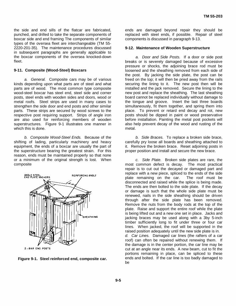
TM 55-203
the side and end sills of the flatcar are fabricated,punched, and drilled to take the separate components ofboxcar side and end framing The components of similartypes of the oversea fleet are interchangeable (TM 55-2220-201-35). The maintenance procedures discussedin subsequent paragraphs are generally applicable tothe boxcar components of the oversea knocked-downfleet.
9-11. Composite (Wood-Steel) Boxcars
a. General. Composite cars may be of variouskinds depending upon what parts are of steel and whatparts are of wood. The most common type compositewood-steel boxcar has steel end, steel side and cornerposts, steel ends with wooden sides and doors, wood ormetal roofs. Steel strips are used in many cases tostrengthen the side door and end posts and other similarparts. These strips are secured by wood screws to therespective post requiring support. Strips of angle ironare also used for reinforcing members of woodensuperstructures. Figure 9-1 illustrates one manner inwhich this is done.
b. Composite Wood-Steel Ends. Because of theshifting of lading, particularly machinery and heavyequipment, the ends of a boxcar are usually the part ofthe superstructure bearing the greatest strain. For thisreason, ends must be maintained properly so that noneor a minimum of the original strength is lost. Whencomposite
Figure 9-1. Steel reinforced end, composite car.
ends are damaged beyond repair they should bereplaced with steel ends, if possible. Repair of steelcomponents is discussed in paragraph 9-13.
9-12. Maintenance of Wooden Superstructure
a. Door and Side Posts. If a door or side postbreaks or is severely damaged because of excessivepressure or shocks, the adjoining brace rod must beloosened and the sheathing removed from each side ofthe post. By jacking the side plate, the post can befreed on the top; it will then be pried away from the railssecuring the lining to it. The new post then will beinstalled and the jack removed. Secure the lining to thenew post and replace the sheathing. The last sheathingboard cannot be replaced individually without damage tothe tongue and groove. Insert the last three boardssimultaneously, fit them together, and spring them intoplace. To prevent or retard end decay and rot, newposts should be dipped in paint or wood preservativebefore installation. Painting the metal post pockets willalso help prevent decay of the wood and rusting of themetal.
b. Side Braces. To replace a broken side brace,carefully pry loose all boards and sheathing attached toit. Remove the broken brace. Reset adjoining posts inproper position and install and secure the new brace.
c. Side Plate. Broken side plates are rare, themost common defect is decay. The most practicalrepair is to cut out the decayed or damaged part andreplace with a new piece, spliced to the ends of the sideplate remaining on the car. The roof must bedisconnected and raised while the splice is being made.The ends are then bolted to the side plate. If the decayor damage is such that the whole side plate must berenewed, nails in the side sheathing should be driventhrough after the side plate has been removed.Remove the nuts from the body rods at the top of theplate. Raise and support the entire roof while the plateis being lifted out and a new one set in place. Jacks andjacking braces may be used along with a 3by 5-inchtimber sufficiently long to fit under three or four carlines. When jacked, the roof will be supported in theraised position adequately until the new side plate is in.d. Car Lines. Damaged car lines (the rafters of a carroof) can often be repaired without renewing them. Ifthe damage is in the center portion, the car line may becut at an angle near its ends. A new beam, cut to fit theportions remaining in place, can be spliced to theseends and bolted. If the car line is too badly damaged tobe
9-5

TM 55-203
repaired in this way, it must be removed and a new oneinstalled. The damaged car line must be disconnectedfrom the side plates and the purlins.
e. Roof Boards. Damaged roof boards may beremoved and replaced. After removing the damagedboards, make a careful inspection for any damage to theinner lining (double-sheathed roofs). Repair suchdamage before putting the new roof boards in place.Minor leaks or light damage can often be repaired byusing sheet metal patches over the affected area.Details of wooden boxcars' roof construction are shownin figure 9-2.
f. Running Boards and Saddles. Running boardson tops of boxcars, while no longer required (paragraph9-14d), where used, will be maintained in a safecondition using AAR Standards as a guide. Nails mustnot be used in running boards; if screws become loose,they should be removed and the holes plugged. Newscrews must be applied in other locations and secureddown tight. When running board saddles becomedecayed or split, they will be replaced (fig 9-2).
g. Sheathing. When sheathing is damaged byshifting loading or other accident, it should be promptlyreplaced. The damaged portion should be removed soas not to damage the remaining portion in the processNew boards should be of good quality without large orloose knots. If sheathing boards are wider at one endthan the other, care must be exercised to keep theboards plumb while nailing them in place. The boardsshould be lightly nailed, narrow end first The other endcan then be pried into plumb position and nailed down.The groove in the last board ,should not be broken off inorder to insert the ,board. The last three or four boardsshould be fitted together in the form of an arch, they canthen be sprung into position and nailed down. Nailsshould not be driven into the tongues of
Figure 9-2. Cutaway of wooden boxcar roof.
the boards, as this splits them and causes leaks. It alsoprevents the boards from fitting tightly together.
h. Flooring. Damaged floorboards should beremoved and replaced with new boards. If only one ortwo boards are to be removed, split one or both of themwith a sharp pointed bar to prevent damage to adjoiningtongues and grooves. In any case when damagedfloorboards are removed, the understructure should becarefully examined for any further damage. The bottomboards of the inner lining must be removed to allowroom for removing the floorboards and replacing them.In applying new flooring, the boards may coverprojecting bolt or rivet heads. Place the board inposition and tap lightly to make an impression of theobstruction. Then cut a notch in the board large enoughfor the bolt or rivet head and secure the board inposition.
i. Lining. When lining is damaged, old boardscan be readily pried loose and new ones affixed intoplace If any large number of boards must be replaced, itis best to begin removing them at the belt rail and workdown, or up, as the case may be. In replacing the newboards, the belt rail should be secured before workingdownward or upward from it. This prevents having thelast board positioned next to the belt rail.
j. End Plate. To replace an end plate, it isnecessary to detach the end of the running board andfree it enough at the attached points so that the end canbe raised and blocked at a sufficient height to allow thework to be done. Tie rods and cover sheets at thecorners must be removed. Parts of the end of the roofmay have to be removed to free the damaged end plateand allow room to attach the new one After the newplate is installed, all disconnected or removed partsshould be replaced in reverse order to that in which theywere removed.
k. Wood Doors. Top-supported wood doorsfrequently bind on the bottom door guides. This iscaused by loose hanger bolts which allow the door todrop down. The hangers should be removed and theholes plugged. Bore new holes and affix the hangerswith new bolts. Pilferage of sealed cars can bediscouraged by insuring that all bolts used to securedoor guides, door stops, door tracks, door hasps, andlike items are fastened with carriage heads to theoutside of the car. In making any repairs orreplacements of door parts, bolts of exactly the rightsize should be used so that they can be securely rivetedover.
9-6

TM 55-203
When the rub strip is applied behind the door orsheathing, all wood screws should be tightened so thatthe heads are flush with the strip.
9-13. Maintenance of Steel Component, CompositeCars
a. General. In many instances wood-steelcomposite cars were originally wooden cars on whichwooden parts have been replaced by steel parts. Manyof these composite cars have steel ends and roofs, butstill retain the wooden sides. This discussion isconcerned with practical measures used in maintenanceand repair of these steel components.
b. Bent Steel Ends. Bent steel ends of compositecars usually can be straightened without removing themfrom the car To straighten an end that is bent outward,the damaged car should be coupled to another car, withthe bent end facing the other car to provide a jackingbase. After coupling, a pair of trestles should be placedbetween the cars, one on each side of the opening. Aplank should be placed between the trestles A heavyjack, with a wide plank set against the good car as abase, is inserted with the base end of the jack againstthe wide plank and the other end of the jack against theapex or high point of the bend in the damaged car. Byoperating the jack, the bend will be forced back intoposition. If it becomes necessary to move the jack frompoint to point, the couplers should be blocked before thejack is removed after the first operation. By placing ablock between the coupler horn and the striking castingof each car, the slack between cars will remain thesame and other jackring operations made easier. If theend is bent in, it will be necessary to remove severallining boards to provide a bearing surface on the endposts for a timber placed crosswise in the car. Thejacking procedure will be the same, except that the workwill be done from inside to outside and the damaged carneed not be coupled If the bend is too severe, too deepand short, or lover too great an area, the piece shouldbe removed and a new end installed.
c. Bent Steel Sides. Steel sides that are bentinward or outward can be straightened by following thebasic procedure outlined for bent ends. A jack and ablock of wood are required, as well as a convenientmeans of providing a base for the jack.
d. Steel Roofs. Steel roofs should be painted atthe first evidence of rust as a preventive maintenancemeasure. Bent sheets or roof caps should be removedand straightened without heating. If too badly bent, they
should be replaced with new parts Rivets that are rustedthrough should be burnt off and replaced. Joints shouldbe drawn up tight (to prevent leaks) before installingnew rivets or welding.
e. Steel Doors. Top-supported doors will beinspected to insure that the top track and hangers aresecurely in position, with no projecting parts whichinterfere with opening and closing the car door. The toptrack must be level; if an unlevel track is found, it shouldbe repaired promptly to prevent further damage to thedoor and the car. Badly bent or damaged tracks must bereplaced.
9-14. All-Steel Cars
a. General. The repair of riveted all-steel andwelded all-steel cars will be very similar, except for theremoval and replacement of parts. In the former case,rivets will have to be removed to free the defective part;in the latter case, a defective portion will have to beburned out. The new piece will be attached in the samemanner as the part removed.
b. Bent Sheets and Side Plates. Bent end or sidesheets usually can be straightened without removal fromthe car by the procedures discussed in paragraph 9-13band c. If a side plate is damaged In only a limited area,the area affected can be disconnected from partsattached to it and then cut out. A similar size side platecan then be spliced into place. Rust spots or smallholes may be repaired by welding a steel patch over theaffected area.
c. Doors, Flooring, and Sheathing The flooringand sheathing or inside lining used in all steel boxcars isin most cases identical so that used in the old all-woodcars The maintenance of wooden superstructure isdiscussed in paragraph 9-12, that of steel doors inparagraph 13e.
d. Running Boards. The installation of boxcarrunning boards as a safety measure on top of newly builtboxcars is no longer required. However, such runningboards on older cars must be maintained in serviceablecondition. Fastenings of running boards should beinspected regularly ,and any loose pieces or rivetsreplaced. Preventive maintenance includes painting atregular intervals to prevent rusting.
9-7

TM 55-203
Section III. REFRIGERATOR CARS
9-15. General
The framework of a refrigerator car is similar to that of aboxcar, with special facilities to provide and maintaintemperatures at a desired level. Refrigerator cars areused to transport perishable commodities or other itemsdependent upon refrigeration or heat to prevent theirdeterioration. These cars employ insulated structures toretain heat or cold as desired. They have thick floors,sides, and roofs, are equipped with ice bunkers or someform of mechanical heating or refrigeration. A numberof US Army standard gage, domestic-type, 50-tonboxcars have been converted for use as foreign serviceice refrigerator cars. These cars have weldedunderframes, all welded steel sheathed superstructure,steel ends, rigid galvanized steel roof, sliding doors andice ,compartments, stationary type, at each end,arranged for full or half stage icing These cars have acapacity of approximately 2,000 cubic feet available forloading. Exterior and interior views of these cars areshown in figures 2-1, 2-2, and 2-3. Discussion herein isconfined to those features peculiar to any type ofrefrigerator cars which presents the major maintenanceproblems. Recently built 40-ton mechanically activatedUS Army-owned refrigerator cars are operated oncertain foreign narrow-gage lines for US forces. Thesecars are maintained by the 'host national railroads undersupervision of US Army personnel as discussed in TM55-205. These cars are mounted on conventional typetrucks, equipped with coil springs and roller bearingjournals. This car is illustrated in figure 2-2.
9-16. Flooring
Refrigerator car floors usually are constructed of twolayers of wood with some type of insulating materialapplied between them and covered with a waterproofingmaterial. The principal problem In the maintenance ofrefrigerator car flooring is to keep the structurewaterproof and free from abrasions caused by impactssustained in loading. If water is permitted to seepthrough the floor, it will adversely affect the insulatingmaterials, nullifying their efficiency. It also causes theinsulation to become soggy and matty, promotingdisplacement by sagging. Water seepage can bearrested only by constant inspection and maintenance.When abraded conditions of the floor covering are foundit must be promptly repaired or replaced. Renewalsmust be treated with waterproofing compounds toprevent leakage.
9-17. Insulation
Insulation is provided by materials of required thermalconductivity. It should be in blanket form, with asuitable backing and should be applied to car sides andends in continuous blankets extending from the doorpostaround the end of the car to the opposite doorpost. Aninsulation blanket will extend the length of the floor andanother the length of the roof. Insulation should be 3inches thick on sides and ends and 3 1/2 inches thick onfloors and roofs. If temperatures in refrigerator cars areunstable or it becomes difficult to maintain adequatelylow temperatures, an inspection must be made todetermine whether any of the structure has beendamaged. If the inner and outer walls, roof, doors,floors, and ends are in good condition, the insulationmust be examined for condition and positioning.Dislocation or disability of the insulating materialgenerally can be detected by differences in temperatureof the outer shell of the refrigerator car. At such points,sections of the structure (lining, etc.) will have to beremoved to gain access to the insulation in the affectedarea. If the insulation has only shifted, it will merelyrequire relocation and reaffixing. If it has become watersoaked or matted, it must be replaced. This sameprocedure is followed in repairing the doors and paddingaround the doors. If the canvas covering the paddingbecomes wrinkled or torn through 'use, it should besmoothed or reattached.
9-18. Doors
a. General. Doors of refrigerator cars generallyare provided in pairs and located centrally in the side ofthe car. They are thick and adequately insulated. Theedges of the doors are beveled, matching the bevel ofthe door frame. This permits free-swing clearances andtightness of fit when the door is closed. Some of thedifficulties that are encountered in maintainingrefrigerator ,car doors include lack of airtightness anddisability of the locking devices.
b. Airtightness. The airtightness of car doors isdependent upon the closeness of fit, and the manner inwhich the padding around the door )has been applied. Ifthe padding was loosely applied, permitting it to becomefolded or wrinkled, leaks will develop. Padding canbecome hardened and lumpy, thus contributing to airleakage. When such conditions are found, defectivepadding will be replaced. Sprung doors or door
9-8

TM 55-203
frames resulting from wood warping may cause leakage.In this event, such members will be replaced and thedoors refitted.
c. Locking Devices. The hardware of refrigeratorcar doors includes the hinges, cranks, locking bars, andlevers. These members generally are constructed ofmalleable iron, affixed with bolts passing completelythrough the door and anchored with a nut on the outside.These locking and hinge devices become inoperativedue to rust, wear, deformation or breakage, andlooseness. If one of the devices cannot be repaired orfirmly affixed, it should be replaced with a new one, andthe portion of the car body or door to which it is affixedbe repaired to afford a satisfactory support or anchorpoint. Airtight closures are not possible if these devicesmalfunction.
9-19. Roofs
a. General. There are several types of roof usedon refrigerator cars: board, plastic, inside or outsidemetal, and all-steel. It is important that car roofs be keptleakproof to prevent decay and corrosion of the carstructure and/or damage to the loading. Roofs and allparts such as roof boards, plastic coverings, metal roofsheets, purlins, carllnes, ridge poles, etc., should beinspected periodically and any leaks or damagerepaired. Neglect of damaged supporting members mayresult in the development of stresses that open seamsand joints, thereby causing leaks in the roof.
b. Repairs. Outer or inner roofs which leakshould be repaired or the leaky member replaced. Inthe case of plastic covering, the leaky portion should berecovered This may be applied directly over the oldroofing. Where cars have inside sheet metal roofs, carewill be taken to insure that 'nails used to secure theouter boards do not extend into the car interior andpuncture the metal lining. This type of repair generallycan be effected without removing the entire roof;however, It may be necessary to remove some roofboards or parts of the running board. If car lines,purllns, ridge poles, or planks must be replaced, itusually will be necessary to remove the entire portion ofroof. In some types of construction, car lines are soinstalled that removal is impossible without disassemblyof the roof. If only one car line must be replaced, it canbe removed piecemeal and a new one installed in twosections, to be spliced after installation Purlins, ifdefective, can be replaced by removal of the roof, or asection of it. Steel roofs deteriorate through rust andcorrosive action. Rusty areas should be cleaned with a
steel brush to remove all traces of oxidation, then theareas should be coated with red lead or some other rustinhibitor, and painted.
9-20. Waterproofing
The greatest single problem in the maintenance ofrefrigerator car superstructures is the prevention ofwater seepage into the inner sections of the car, walls,ends, and floors. This seepage will In time corrode themetallic members of the structure and decay thewooden portions. To correct this action waterproofing isrequired Various remedies include the use ofcompounds and the application of plastic sheets.Impregnating all lumber used with a creosote mixturemakes the material highly resistant to moisture. Whenrepairs are made to the car body, all joints should besealed with waterproofing materials. The areaimmediately behind the ice bunkers or brine tanks is acritical area and requires greater care because of itsproximity to condensate water and brine solutionscontained in these tanks or0 emanating from them. Inthe case of box bunkers, in which the walls are formedby the ends and sides of the car, waterproof constructionand repair are essential.
9-21. Overflow Pipes
Overflow pipes are used in conjunction with brine tanksand are provided to drain off excessive moisture As theice melts, the brine solution rises in the-tank until thelevel of the overflow pipe is reached. At this point,excess solution is drained into a tank and retained to bedischarged later, or when no damage to the tracks androadbed will ensue. Overflow pipes become cloggedwith sludge and incrustations. This must be removedduring routine maintenance and the pipes thoroughlycleaned, since a stoppage of the overflow pipes willresult in overflow of the brine tanks and flooding of thecar. The overflow pipe valve will be periodicallycleaned also and maintained In good working order.
9-22. Bunkers
a. General. In some refrigerator cars, theretaining wall or box bunker bulkhead is used to formone end of the ice bunker. In these cars the bulkheadsare arranged as collapsible members that may be swungupward, or to one side, and fastened out of the way Thisis done when commodities which do not requirerefrigeration are transported, so the space normallyoccupied by
9-9

TM 55-203
the bunkers may be used for loading. This unit must bemaintained in good order; the fastening devices shouldbe inspected to assure that they will retain the bulkheadin position. If the bulkhead is permitted to shift, it maydamage the loading; if a bulkhead in use as a wall fails,it will permit the ice to mix with and damage the goodsbeing shipped. Antirust and corrosion measures will betaken for all metal portions (para 9-19b).
b. Basket Bunkers. Basket bunkers (when used)are hung just below the roof in the center of the car,applying refrigeration where temperature is the highest.In some cases, brine tanks are similarly installed Thesebunkers and tanks must be removed periodically andthoroughly cleaned. Any rust or corrosion should beremoved and coatings of preservative material applied.If leaks develop, the tanks must be removed and theholes soldered.
Section IV. GONDOLA CARS
9-23. General
The gondola is an open-top freight car with sides andends. The floor or bottom is level and may be solid orprovided with bottom doors. They are used for thetransportation of bulk freight. Classifications includehigh side, low side, drop end, drop bottom and generalservice. A typical drop end type gondola is illustrated infigure 9-3.
9-24. Oversea Fleet
The knock-down 40-ton oversea fleet includes bothhigh-side (48-inch) and low-side (18-inch) gondolas.These are basic 40-ton flatcars with sides and endsadded. The ends are fixed, and the sides have pressed-steel truss members with a substantial chord angle.Sheathing is 1 1/2-inch tongue and groove wood. Sincethe basic flatcar body is designed for 40 tons, the sidesare not primarily designed to serve as truss membersThe Jow-side unit may be provided with drop ends,which drop outward. Because of its 18-inch side
Figure 9-3. End view, drop-end gondola.
height the low-side gondola will serve as an auxiliary forthe flatcar fleet (TM 55-2220-201-35).
9-25. Maintenance and Repair
a. General. Gondola cars as a class receive theroughest usage of any freight cars, and as a result aresubject to corrosion which weakens the car structure.Since this class of car represents a large proportion ofall freight cars in service, adequate maintenance andrepair schedules must be established and adhered to. Itshould be re- membered that as the gondolas of the 40-ton oversea fleet are basically flatcars, maintenance oftheir superstructure is, therefore, a matter of upkeep ofthe sides and ends. When stripped of sides and ends,damaged or otherwise, they can be returned to serviceas flatcars. Conversely, since gondola sides and endsare unit packed for shipment and storage, flatcars maybe converted into gondolas at depots where stores areavailable, at railway salvage depots, or as a last resortby cannibalization.
b. Major Repairs. Repair work of a major naturebegins with dismantling the car and removing allmaterial or mechanisms that require straightening,repair, or renewal. The car is then moved to wherenecessary repairs can be made to those parts of the carremaining intact. When truck repairs are indicated, theframe is jacked and the trucks moved out as outlined inparagraph 4-4b; new and repaired floor sheets can befitted while the trucks are out. Side and end repairs canbe made at this time, also. These repairs may includereplacement of repaired sections, renewal of parts, allriveting and welding required on the superstructure andthe installation of safety appliances. Car trucks,couplers, airbrake cylinders, etc., are reapplied,airbrakes tested, and the car is ready for painting andrelease for service.
9-10

TM 55-203
c. Minor Repairs. Defective side or floor sheetmay be cut out at the stakes or at cross bearer and sillsto make light or minor repairs (organizational and directsupport maintenance). Patch sheets will then lap overthe edges of the remaining portions of the old sheet. Ifthe sides become distorted (steel-sided cars) from thestrain of excessive loads, a turn buckle bar of sufficientlength to hook over the sides of the car will pull themback into shape. If the side of a car is bent in, it can bejacked out to the proper position with an ordinary jack.The side plates at the opposite side of the car can beused as an anchor or base for the jack by bracingproperly with thick timbers so as to distribute the forceover a wide area. When the end of a gondola is cavedin, it may be jacked out by placing heavy timbersagainst the crosstie, one on each side near the centersills, and arranging jacks between the timbers to push
out the caved-in portion. At the .same time a jackshould be placed across the end of the car to push outthe corners. If the end is 'bulged out, it may be jackedback into position with a jack based on another carcoupled end to end with the bulged car. Cars withdamaged ends often have pulled in corners. Theseshould be shaped to the proper position by jacking at thesame time repairs are made at the ends. Repair ofdamaged sides and ends of 40-ton gondolas mayinvolve only replacement of wooden parts. This requirescarpenter skill only. If side structural steel trussmembers of high-side gondolas or steel posts of low-side gondolas are damaged to the extent thatreplacement is necessary, the type of repair and theplace for performing repairs becomes a matter ofjudgment on the part of the responsible maintenancepersonnel.
Section V. HOPPER CARS
9-26. General
A hopper car is a freight-carrying car with the floorsloping from the ends and sides to one or more hoppers,which are capable of discharging their entire load bygravity through the hopper doors, a self-cleaningfeature. The hopper compartment doors may beopened or closed as required. The door operating gearconsists of a shaft, ratchet gear, paw], and chainlinkage. All hopper doors are provided with lockingdevices to secure the doors in closed position. Coveredhopper cars are permanently inclosed, equipped withtight-fitting covers and doors. They are used for theshipment of chemical products (sulphur, etc.) in bulk.
9-27. Major Repairs
a. Dismantling. For complete rebuild or majorrepairs, hopper cars are disassembled on an outlyingtrack in the following manner. At the first position theends, crosstie braces, side gussets, and coupler carrierbolts are removed. The car is then moved to thesecond position where the sides and long hoods aredismantled. Side sheets are not cut loose at this time.Couplers and draft riggings are then removed and partsneeding repair sent to the proper shop. At the nextposition the hopper slope sheets, floor sheets, crossbridges, drop doors, hinge pins, and hinge butts areremoved. If the cross-bridge sheets are to be scrapped,it will be necessary to cut off the crossbridge and centercross-bridge braces. At the final dismantling positionthe remaining parts are removed. These parts include
inside hopper sheets, long hood support, lever guides,floating lever guides, center sill stiffeners, hinge, buttsupports, outside sill stiffener and center sills, bodycenter plates, back center sill fillers, center braces, draftsills, draft and end sill gussets, top follower guides,handbrake steps, brake mast step, uncoupling device,body bolsters, and airbrakes; old rivets should beremoved from all material to be repaired or used inreplacement.
b. Reassembly. Material to be reapplied to thecar should be positioned at the proper place along theassembly track. Bolsters and diaphragms should beassembled at some point other than the erecting trackso that they can be applied to the car in a singlecompact unit. Reassembly is accomplished at severalpositions along the erecting track in the followingsequence:
(1) After assembly, place the body bolstersand diaphragms on four trestles at opposite ends of thefirst position. Fit the center sill to the bolsters andsquare them. Apply the following units: long hoodsupports, body side bearings, bolster diaphragm fillers,end sills, side sills, striking castings, striking castingbraces, draft attachments, top follower guides, centerbraces, center plate fillers, sill stiffeners, centercrossbridge brace, brake rod anchor assembly, brakerod anchor, body center plates, lever connection guides,floating lever guide fillers, and hinge butt supports.
9-11

TM 55-203
(2) Lower the car body, with this equipmentinstalled, from the trestles onto service trucks and roll tothe next position to be riveted.
(3) Apply the following parts to the rivetedconstruction: inside hopper sheets, inside hopper sheetangles, side sheet gusset plates, cross-bridge sheet,cross-bridge braces, hinge butts, and drop doors.
(4) Move car to floor construction positionand apply the following parts: floor strut angles, longhood, outside hopper sheet, angles, and the lower floorangles.
(5) Move car into position for riveting thesemembers To facilitate work underneath the car, it shouldbe raised from the service trucks, blocked at the draftsills, and lowered to rest on them.
(6) Upon completion of riveting, retruck thecar and move to next position for application of endsand sides. Then apply following parts: corner caps, sidesheet ties, tie reinforcements, center floor plate fillers,draft and end sill gusset plates, and diagonal struts.
(7) Move to next position for riveting ofthese parts and the application of safety appliances.These include inside steps, brake mast supports, brakemast rests, sill steps, grab irons, and ladders.
(8) Move car to final assembly position. Removethe service trucks and apply the repair trucks. After carbody is lowered on trucks, connect the brake rigging andinstall draft gears, couplers, carrier irons, and allrequired locknuts. Gage the car for proper couplerheight, check side bearing clearances and testairbrakes. Car is then ready for painting.
9-28. Minor Repairs
Because of the basic similarities of hopper cars andgondolas, the procedures outlined in paragraph 9-25cgoverning light repairs to gondolas are also applicable tohopper cars. Drop doors and drop-drop operatingmechanisms are also quite similar on gondolas andhoppers and the same repair procedures will apply. Thesides of hopper cars, near the bottom, have a tendencyto rust out prematurely from rain, melted snow, etc.,seeping through the sand, coal, or other bulk cargoesthey usually are loaded with. Often such a car cannotbe shopped and a temporary repair is required. Thiscan be accomplished by affixing repair sheets to theinside of the car of adequate size to cover the damagedarea. Replacement plates should be bolted or welded inposition as deteriorated side sheets will rarely withstandriveting. Repaired areas should be painted to retardfurther corrosion.
Section VI. DUMPCARS
9-29. General
An air dumpcar is an all-metal car so constructed that itscontents may be discharged to either side or both sidesof the track through doors in the car sides or drop doorsin the floor; by means of an inclined floor and sidedoors; or by tipping the car body sidewise by means ofcompressed air secured from the trainline. Dumpcarsare used to move large quantities of earth in excavationand construction work along rail lines. It is used forditching, trestle filling, coal handling, and emergencywork occasioned by landslides or washouts. Themajority of side dumpcars are provided with sides thatturn down and out coincident with the tilting of the body.As the entire side of the car turns down, it forms a chuteover which the load in the car is discharged (fig 9-4).
9-30. Operation
The dumpcar body is mounted on a steel underframe,pivoted longitudinally over the center sill so as todischarge on either side. When dumping, the hinges,
which are riveted to the center sill under the car body,rock on the pedestal castings, which are riveted to thecenter sill. Vertical dump cylinders on each side of thecar perform the dumping and righting of the car body.The body is supported in such a manner that allmembers between it and the underframe are incompression, with the result that the shock of loading iscarried directly through the truck spring to the roadbedAir dumpcars are provided with air storage reservoirslocated on the car and charged through the trainlinefrom the locomotive. Dumping of air dumpcars usuallyis accomplished by turning the handle of a control valvelocated on the platform of the car. This charges orexhausts the operating (air) line. The locks are operatedby a separate air cylinder connected to the operatingline through a cutout cock. Closing the cutout cockleading to any latch cylinder cuts out the dumpingoperation of the particular car. The dump body is tiltedby the dump cylinders (as shown in figure 9-4) one ofwhich is mounted on each end of the body. On somecars the same pair of cylinders is used to tilt the body ineither direction, reversal of dumping being accom
9-12
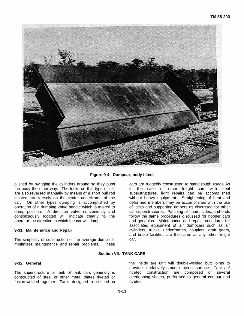
TM 55-203
Figure 9-4. Dumpcar, body tilted.
plished by swinging the cylinders around so they pushthe body the other way. The locks on this type of carare also reversed manually by means of a short pull rodlocated transversely on the center underframe of thecar. On other types dumping is accomplished byoperation of a dumping valve handle which is moved todump position. A direction valve conveniently andconspicuously located will indicate clearly to theoperator the direction In which the car will dump.
9-31. Maintenance and Repair
The simplicity of construction of the average dump carminimizes maintenance and repair problems. These
cars are ruggedly constructed to stand rough usage Asin the case of other freight cars with steelsuperstructures, light repairs can be accomplishedwithout heavy equipment. Straightening of bent anddeformed members may be accomplished with the useof jacks and supporting timbers as discussed for othercar superstructures. Patching of floors, sides, and endsfollow the same procedures discussed for hopper carsand gondolas. Maintenance and repair procedures forassociated equipment of air dumpcars such as aircylinders, trucks, underframes, couplers, draft gears,and brake facilities are the same as any other freightcar.
Section VII. TANK CARS
9-32. General
The superstructure or tank of tank cars generally isconstructed of steel or other metal plates riveted orfusion-welded together. Tanks designed to be lined on
the inside are unit will double-welded butt joints toprovide a relatively smooth interior surface. Tanks ofriveted construction are composed of severaloverlapping sheets, preformed to general contour andriveted
9-13

TM 55-203
together at the overlapped seams. Tanks vary in designin relation to commodity transported Some, like Army-owned tank cars used for the transportation of petroleumproducts, are constructed to provide one largecompartment (fig 2-6), other types are divided intoseveral compartments so as to carry different kinds ofliquids at the same time.
9-33. Construction Features
a. General. The superstructures of tank cars(shells) must be constructed of materials which resistcorrosion, or be lined with corrosion-resistant material.For this reason, tank shells are built of alloyed steel,nickel steel, or aluminum. Insulation is sometimesrequired to maintain an even temperature for certaincommodities. Some viscous liquids require theapplication of heat to facilitate unloading. This normallyis accomplished by steam coils installed inside the tankshell.
b. Dome. Most tank cars are equipped withdomes (fig 2-6). These are cylindrical chambers affixedto the top of the tank to provide a means of filling thetank to its full cubic capacity. Domes also serve asreservoirs for the accumulation of gases and fumes thatdevelop in the transportation of some liquids. The sizeof the dome is governed by the size and class of thetank to which affixed. In multiple-compartment tanks,each compartment is equipped with a separate dome.Domes are provided with vents or safety valves toexhaust accumulated gases or vapors. The details ofdome and outlet valve arrangement are shown in figure9-5.
c. Outlet Valves. These valves (fig 9-5) areinstalled on the underside of the tank and provide ameans of emptying the contents of the car. They mustbe constructed in such a manner that they will becapable of passing the type of lading carried, whether itbe free-flowing liquid (aviation gasoline) or heavyviscous materials (crude oil, molasses). The outletvalve must be able to pass the contents without blockingor stopping. It must also be made of materials whichresist corrosive action. Outlet valves extend downwardfrom the bottom of the tank to a point below theunderframe members, providing a ready access. Thesevalves are opened and closed by a mechanism housedin the valve and activated by a rod which passes fromthe valve upward into and through the tank body, and isaffixed to the inside of the dome housing.
Figure 9-5. Arrangement of dome and, bottomdischarge outlet.
d. Tank Cars in Theaters of Operations.Petroleum products are the principal commoditiesmoved in tank cars in oversea theaters of operations.Tank cars of AAR, DOT, and CONUS specifications,modified by emergency austerity demands, are standardfor oversea theaters. The United States type center-sillconstruction between bolsters is incorporated in cardesigns, and side buffing is provided for In designswhere hook-and-link couplers are used as shown infigure 7-6. Shock is absorbed by diagonal bracingapplied to the bolster center-sill connection; this ispreferable to the conventional European use of side sillsfor buff resistance Standard bottom outlet valves anddome safety valves are incorporated in tank carspecifications, which are available from the US ArmyMobility Equipment Command, St. Louis, Mo.
9-34. Maintenance and Repair
a. General. A leaky tank is one of the morecommon defects encountered in tank car maintenance.The first and most vital tank car maintenance principleis: CAUTION-NEVER APPROACH A L,EAKING TANKCAR WITH AN OPEN LIGHT. This is applicablewhether or not the inspector knows what the ladingconsists of. In fact and in practice, an open light(match, torch, candle, or lantern) must NEVER be usedin the inspection of tank cars, empty or loaded.
9-14

TM 55-203
b. Leaking Tanks. A leaking tank car shouldhave its load transferred as soon as possible; if leakingbadly, temporary repairs must be accomplished. Onemethod is to stuff waste or rags, impregnated with aheavy lubricant into the opening to arrest the flow.Where the rupture is not too great, soap or clay may beadequate. These are strictly temporary expedients, onlyperformed to provide time to transfer the lading toanother car. If possible, the empty tank car selected toreceive the transferred lading should have held a similarcommodity. Otherwise the lading may be contaminatedor two noncompatible substances become mixed. Ifpossible, the load should be transferred by gravity flow.If a gravity transfer cannot be made, siphon or pressuremay be used. Air pressure should be Judiciously usedand only on cars loaded with heavy oils, and at a verylow level Leaks in seams can be calked temporarily bypacking them with twine or lead-wood pushed into placewith a sharpened piece of wood or bronze After thetwine calking has been tamped into place, soap shouldbe patted over it to form a ridge. Tools made of ferrousmetals must not be used in tank car repairs of this type,since there is a danger of igniting flammable lading orgases by sparks that might occur when ferrous metalsare brought into sharp contact. A dent in a tank cardoes not require any attention if not leaking.
c. Outlet Valve Leaks. Many leaks occur at theoutlet valve underneath the tank. These generally arecaused by a leaking valve inside the tank. This type ofleak often may be stopped by tightening the cap on thebottom of the tank nozzle. If this does not remedy thetrouble, a blind gasket can be placed over the end of thetank nozzle and the cap screwed up tight against it.Sometimes such leakage can be stopped by removingthe dome cover and moving the valve up and downseveral times. Bad leaks often develop in the tanknozzle of the outlet valve, because of freezing in coldweather. As water is heavier than oil, any formed fromcondensation will be at the bottom of the tank and befirst to run out. This water often freezes in cold weather,bursting the tank nozzle, and causing a leak when itthaws. In such cases, the leaky valve should bereplaced after the car is emptied and before reloading.
d. Tank Heads. These members, the ends of thetank shell, are frequently bent. This results from beingstruck by the shifting load of another car or as a result ofa blow from a projecting object or building. Such dentsmay be straightened by bumping them from the insidewith a heavy maul or a tool made from an old axle. Tofacilitate this operation, a little heat may be applied tothe dented areas of the tank head while the bumping is
being done. The tank head must never be heated to abright red heat, as this will cause the member to buckle.When straightening tank heads, never strike the headdirectly, as that will mar the sheet or member It ispreferable to use a flat-faced swage or wooden maulagainst the surface. If the tank head is badly staved in,it can be straightened by means of a jack placedbetween timbers and braced against the other end of thecar. While it is frequently possible to straighten dents intank heads and shells without removing the tank fromthe car frame, more ,extensive damage requiresremoval. The tank should then be set up on skids orlarge horses for repairs.
e. Shell Plates. The repair or straightening ofdented shell plates generally is performed in the samemanner as repairs to tank heads, discussed in d, above.When it is necessary to remove a tank plate, care mustbe taken to avoid damaging it when removing the oldrivets. Rivets should be driven (headed over) on theoutside and bucked on the inside, using a well designedbucking bar instead of another hammer. Rivets must betight. A loose rivet can be detected by holding a fingeron the rivet head and tapping the rivet lightly with ahammer. If loose, it will vibrate slightly. Loose rivetsmust never be calked. If they leak, they must bereplaced.
f. Safety Valves and Vents. The lading often runsinto the top of the safety valve when the car is beingloaded. Asphalt or similar products may congeal andprevent the valve from unseating at the prescribedpressure. If inspection indicates a faulty safety valve,remove the valve from the tank. To disassemble astandard safety valve, remove the valve plug from thecenter of the valve. Back out the valve stem until thespring follower and spring are detached. Remove thevalve and valve stem from the housing and inspect thevalve. If the valve or valve seat is pitted or rough, thecontact surfaces may be ground smooth with emerypowder. All parts of the valve should be cleaned beforereassembly. Spring tension will be adjusted and thereassembled valve tested for correct pressure opening.
g. Dome Covers. Dome covers require littlemaintenance, as they seldom fall in service. Domecovers are provided with 1/2-inch holes just underneaththe flange of the cover. These holes
9-15

TM 55-203
are necessary to permit the release of gases andpressure less than that required to lift the safety valve.Dome covers without these holes should never beapplied. It is necessary to inspect to see that the domecover chain is secured to the tank so that the covercannot slip off and fall.
h. Tank Car Tanks. After any repairs requiringwelding, riveting, calking of rivets, or hot or cold formingto restore tank contour of tank cars used in Interchangeservice in CONUS, the tanks must be retested asprescribed by paragraph 173.31, DOT Regulations (49CFR Part 173) before return to service. Glass, lead, orrubberlined tanks must be retested before the lining isrenewed. Interior heater systems must be retestedbefore return of the car to service after repairs to, orrenewals of any part of the system.
9-35. Tank Cleaning
a. General. When it is necessary to repair a tank,It must be thoroughly cleaned so as to be safe to enter.Often the fumes remaining after the load has beendischarged are highly flammable or toxic. Theprocedures following are prescribed for differentcommodities.
b. Tanks Carrying Oils. This type of tank is bestcleaned with steam. A jet of stem will be blown into thetank, the steam vapor will condense on the tank walland run down to the bottom of the tank, taking the oilwith it. Before applying the steam, it is necessary toremove the outlet cap and to open the tank valve,thereby allowing the condensate and oil to run out. After4 to 5 hours of steaming, a carman should enter thetank and sweep out the residue The final step is athorough flushing with cold water.
c. Tanks Carrying Acids, Fats, Heavy Greases.Tanks that have transported these commodities must becleaned by boiling out. This is accomplished by fillingthem with water and adding four or five hundred poundsof caustic soda. A steam hose should then be insertedinto the tank and turned on. Tanks of this type shouldbe boiled for 48 hours before the solution is drained out.After this treatment, the tank must be thoroughlywashed out with cold water before it is safe for aworkman to enter. As this caustic solution will causepainful burns if it comes in contact with the skin, rubberboots, gloves, and oil-skin clothing should be worn whenthe solution is handled.
Section VIII. FLATCARS
9-36. General
The Department of Army 40-ton flatcar is speciallydesigned for foreign service as the basic component ofthe knocked-down fleet The other components (excepttank cars) are simply flatcars with their respective typesof superstructure (high- and low-side gondolas andboxcars) added. These components are shippedpackaged and are easily assembled as outlined in TM552220-201-35. For the movement of ordnance andengineer materials, or other equipment weighing over 40tons, a standardized Army 80-ton flatcar has beendesigned to meet most theater operating conditions. Noconversion of this car is anticipated. It is mounted onsix-wheel (3-axle) trucks to avoid exceeding the low axleload limit on track and bridge structures of foreignrailways. The 80-ton flatcar, like the 40-ton flatcar, isshipped knocked down and packed so that it can beassembled in the field with minimum effort.
9-37. Depressed-Center Flatcars
A minimum design capacity load of the depressed-center flatcars (fig 2-5(2)) In service on the railroads ofthe United States is 70 tons. Body-mounted airbrake
cylinders and foundation brake gears of theconventional type of flatcar cannot be used indepressed-center flatcars; hence, brake cylinders with aseparate foundation gear for each truck are required.Cylinders may be truck mounted or body mounted. Railmovement of ordnance and engineer material and otherequipment with vertical dimensions exceeding thosepermissible for mounting on regular 40or 80-ton flatcarsis sometimes possible on depressed-center flatcars;however, the load limit of the depressed-center flatcarwill not equal that of the regular 80-ton flatcar. Theusefulness of the depressed-center car is measuredprimarily by the added headroom it affords.
9-38. Maintenance and Repair
a. General. The life expectancy of flatcars- ismaterially affected by the adequacy and quality of themaintenance and repairs performed. This is because ofthe tremendous load transported on flatcars. Thestructural material used in flatcar construction consistsof members rolled, shaped, extended, or cast. Thesevarious members are combined and fabricated to form acomplete struc-
9-16

TM 55-203
ture. This is generally accomplished by riveting and/orwelding. Since many CONUS flatcars have woodendecks or flooring and many foreign flatcars are partly ofwood construction, repairs to both types will bediscussed.
b. Repairs to Wooden Flatcars. The repair ofunderframes was discussed in chapter 5, so thisdiscussion is limited to superstructure repairs only. Theonly superstructure on the average flatcar is theplatform or flooring. The wood flooring normally used isof 1 3/4-inch lumber, squared or provided with a shiplapJoint. The floorboards are cut out for the side and endstake pockets. When renewing a car floor, all old nailsand spikes should be removed and the car structurerepaired if needed. When old flooring is relaid or newflooring is applied, it should be fastened with 30or 40-penny spikes, depending on the thickness of the lumberFlooring usually is milled In widths that lie with a face of5 1/4, 7 1/4, or 9 1/4 inches. Two spikes should be usedin each end of the board where it Is affixed to the sidesills, two more in the area over each center sill, and onewhere the board is affixed to the intermediate nailingstrips. This applies when 5 1/4-inch boards are used,additional spikes may be necessary when wider boardsare laid Flooring should project about 1 inch beyond theouter edge of the side sill. It must be laid In alinement ifthe boards are presawed to length. If random and milllengths are used, they may be marked with a chalk lineand sawed straight across after they are nailed intoplace. Any sill that is slightly tipped or twisted must beblocked straight before the flooring is applied. It is alsonecessary to see that the car is properly trussed to
secure the required camber or curvature of the sillsbefore laying a new floor, since this enables the car towithstand concentrated loads on its center.
c. Repairs to Steel Flatcars. Steel flatcars are ofthree general types: the ordinary flatcar with steel sillsand wood or steel floor, the depressed center flatcar,and the well-hole car. Cars of the latter types aregenerally equipped with riveted steel floors. When steelfloors are used, they are riveted to the sills with soft ironrivets. These rivets have large flat heads and areinserted from the top and driven from the lower side ofthe car floor. The floors generally are made of steelplate, riveted directly to the side, center, andintermediate sills of the car Defects developing in thesefloors usually are caused by the lading they carry Insome cases, the floors warp and buckle; in others, holesmay be punched through the floor sheets. Often rivetsare sheared off by lading sliding across the floor. Holesin a steel floor may be repaired with patches, or theentire sheet can be replaced, if necessary. Floors thathave buckled may be removed and straightened ,orrelaid It is often necessary to weld over old rivet holesand punch or drill new ones, because buckled memberstend to stretch when straightened Sheared rivets shouldbe replaced whenever found. Other repairs todepressed-center and well-hole flatcars areaccomplished in accordance with methods applicable toordinary steel flatcar repair.
9-17

TM 55-203
PART THREE
HEATING, LIGHTING, AND AIR CONDITIONING
CHAPTER 10
TRAIN LIGHTINIG
10-1. General
The three commonly used systems for train lighting arethe axle-generator system, the head-end system, andthe storage system.
a. Axle-Generator System. The axle-generatorsystem is the one most frequently used for train lighting.In this system the drive is the means of transmittingpower from the axle of a railway car to the generator.The types most generally used are the belt drive and thedirect drive. The belt drive is the earlier developmentand is still found on many cars Exposure of theoperating mechanism to severe winter weather and tothe dust and grit encountered in hot, dry weather createsproblems in wear, loss of tension, and generalmaintenance that have been impossible to overcome.Moreover, the larger generators demanded by airconditioning have made the belt drive impractical. Themore efficient direct drive does not present theseproblems, since a shaft replaces the belt. An additionaladvantage of the direct drive is that power transmissionlosses are relatively low.
(1) Belt drive (fig 10-1).
(a) The driving pulleys or sheaves areaffixed to the car axle, and the driven pulleys aresecured to the armature shaft of the generator. Overthis set of pulleys, an endless flat belt or a V-belt isinstalled, and as the car axle rotates, the belt transfersthis power to the generator The combined V-belt andgear drive employes four or six V-belts to drive a set ofsheaves mounted on a gearbox hung from the truck endsill. These sheaves drive a gear shaft which, by meansof a bevel gear, drives the generator mounted on the carbody through a propeller shaft equipped with universaland slip Joints.
(b) A spring arrangement givespractically constant belt tension throughout anymovement of the generator caused by belt stretch or bythe car's rounding a curve. This arrangement, termed
an underframe suspension, gives constant belt tensionfor 8 inches of generator travel.
(c) The suspension must be lubricatedproperly to prevent wear of the parts and loss of properalinement Grease may be forced through the bronzebearings in which ample grease space is providedGrease can be applied by a compression cup installed inthe supporting shaft and bearing or by a grease gun ifthe proper fittings are applied to the suspension. As thebearings are not subjected to heating, petrolatum Ispreferable to cup grease.
(d) When necessary to remove thegenerator from the suspension, block up the generatorto take the weight off the suspension shaft.
Loosen the lockscrew and remove the grease cap at oneend. Then insert a bolt into the tapped hole in the endof the suspension shaft and pull the shaft out of thebearings and lugs. The Insertion of the bolt provides ameans of applying a drawing force; or if the shaft is free,it serves as a handhold with which the shaft may bewithdrawn. If the supporting shaft resists efforts towithdraw it, remove it by further disassembly of thebearing cap.
(2) Direct drive.
(a) Direct drive generally employs aminimum number of moving parts. In one type, allwearing parts run in a constant bath of light oil wherethey are completely sealed and protected from ballast,dirt, water, snow, Ice, or other foreign matter. This typeof drive transmits power from the axle of a railway car toa generator through a mechanism consisting of a gearunit, a propeller shaft, and a clutch This drive consists ofan unsplit hypoid gear mounted in a gearcase ,on astandard axle (fig 10-2). This gear is in mesh with apinion connected to a propeller shaft suspendedbetween universal joints, one of which
10-1

TM 55-203
Figure 10-1. Arrangement of an axle-generator belt-drive system.
is attached to an automatic clutch installed on thegenerator. The hypoid gear, through the pinion,universal joints, and propeller shaft, drives a generator(fig. 1043) or in some cases a generator mounted on thecar body. The automatic clutch mounted between thegenerator and the propeller shaft completelydisconnects the drove from the generator in case ofexcessive overload 'or when the car speed falls below 5miles per hour. It also eliminates shock loads when carsare being shunted. The automatic release permitsmotoring of the generator for electrical inspection ordriving of the generator motor or generator by standbyalternating current.
(b) Correct lubrication is the mostimportant item of maintenance in connection with thesedrives. Proper lubricants must be used and the correctoil level maintained to prevent drive failure Extremecare must be exercised to prevent the admission of dirtor other foreign matter into open filler plug holes.
(c) If inspection reveals a rapid loss ofoil, the oil seals should be examined and replaced ifnecessary. Oil leaks must be corrected as soon aspossible. They may be detected by a wetting of thesurface around the sealed points. A slight seepage is a
natural condition.
(d) A program of regular inspectionand replacing of small parts will prevent excessive wearand possible generator drive failure. This includes thoseparts apt to become worn, loose, or broken, such asrubber mountings, bolts, nuts, washers, oil seals,gaskets, bearings, etc. Drives correctly installed andmaintained will operate satisfactorily without attentionfor long periods.
b. Head-End System.
(1) The head-end system was one of thefirst electrical systems to be used in train lighting. Inthis system, the generator may be located in thebaggage car and driven by a steam turbine or a gasengine, or it may be installed on the tender orlocomotive and driven by a steam turbine. In a fewcases, the head-end system has been used on modernstreamline trains, power being generated by two or morediesel-engine generator sets located in the locomotiveor in a power car at the head of the train.
10-2

TM 55-203
Figure 10-2. Generator drive gearcase mounted on a standard axle.
Figure 10-3. Type GP 25-kilowatt generator.
10-3

TM 55-203
(2) The main advantage of the system is itseconomy of operation and maintenance, since itemployes only one generator for the train rather thanseparate generators for each car.
(3) The system has two majordisadvantages. In making up trains, it is necessary(unless the generator is on the locomotive) to have a carwith a generator at the head end. All cars must beequipped with sufficient batteries to provide satisfactoryillumination when uncoupled from the generator car ofthe power source.
(4) Power is delivered to the cars by a three-wire trainline which serves to compensate for voltagedrop and to keep the same voltage at all lamp socketsthroughout the train. The line runs the length of the trainand has flexible connections between cars. Indicatingand control devices normally are located near thegenerator to facilitate control of the system.
c. Storage System. The power supply of thestorage system consists of storage batteries carried withthe individual cars, usually in a box ,under the car. Thebox has a hinged door for access. The bottom of thebox generally is grated rather than solid to keep thebatteries cool A charging connection is provided forcharging the batteries at terminals during layoverperiods As the battery voltage is reasonably constantduring the normal discharge period of the battery, noauxiliary equipment or controls are employed. The sizeof the batteries in the storage system is necessarilylarger than the batteries required with head-end or axle-generator systems for the same load. The principaladvantages of the system are its simplicity and smallinvestment cost. In older types of passenger cars wherelighting standards are low and no air conditioning isprovided, the storage system may be used satisfactorily.However, the system is impractical for modern carsbecause of their increased loads and longer runs As thebatteries of a storage system cannot be charged whilethe car is underway, it is necessary to have adequatecapacity for the longest period of use and to scheduleenough recharging time during layover periods.
10-2. Electrical Equipment
a. General. The principal parts of electric lightingequipment for railway cars are the generator, generatorregulator, lamp regulator, pole changer, storagebatteries, and electrical fixtures. The care andmaintenance of this equipment is essentially a matter ofregular inspections and keeping it meticulously clean.
b. Regulators. Regulators should be checkedperiodically. This inspection consists of cleaning the
carbon and pivot pins, and removing any friction in thepins or supports. Carbon is cleaned by releasing thepressure on the carbons and then blowing the dirt outwith an air hose, or moving the carbons up and down ontheir support rods by hand The pins may be cleaned bypolishing them with very fine emery paper; the pinholesshould be reamed to remove any foreign matter. Uponreassembly, check all connections for tightness andcleanliness.
c. Pole Changer. To maintain the polarity of anaxle generator, an automatic device called a polechanger is used. This unit is provided in one of threetypes: rotating, mechanical, or electrical. 'Thesedevices generally are a part of the commutator endhead and may be removed from the head for cleaning.
(1) Rotating type. This type shifts thebrushes of the generator when the direction of axlerotation changes. On a two-pole generator, brushesshift 180° or through an angle equal to the pole pitch, ona four-pole unit, they shift 90°. The advantages of arotating type of pole changer are that the continuity ofthe armature circuit is free of the interference that mayoccur in the use of switches and contacts, and thebrushes can take a "lead." This is not possible in fixedtypes.
(2) Mechanical type. The mechanical typeof pole changer consists of a reversing switch which ismechanically operated by rotation of the armature shaftand which opens and closes by rotation of the shaft Inone direction or the other.
(3) Electrical type. The electrical polechanger employs a reversing switch, generally operatedby solenoids. This device is placed inside the car withother electrical apparatus. The switch is thrown one wayor the other automatically, depending upon the directionof rotation of the generator armature.
d. Storage Battery. The storage battery used inelectrical lighting in railway cars in an electrochemicaldevice consisting of a number of cells connected inseries. It receives and stores electrical energy anddelivers it to the circuits as needed. There are threetypes of storage batteries in common use: the nickel-iron alkaline, the lead acid, and the nickel-cadmiumtypes. Proper maintenance of storage batteries requirethe carman to understand the factors that influencebattery condition and life. Some of the conditionsencountered in servicing railway car battery installationsinclude overcharging and undercharging, cor
10-4

TM 55-203
roded terminals which prevent the delivery of sufficientcurrent under heavy load; cracked or broken cases withresultant loss of electrolyte, short circuits within thecells; worn out plates, chipping of active material;freezing, sulphation; growth of positive plates; shrinkageof negatives; and electrolyte below the tops of the platesTerminals and cable connections must be kept clean ofcorrosion and electrolyte maintained at level adequateto cover the plates. Defective batteries will be replacedwith new or rebuilt ones.
(1) Alkaline type. The alkaline cells (fig 10-4) consist of nickel-plated steel grids containing tubes orpockets to hold the active materials of nickel and ironoxides. The electrolyte for the nickel-iron cells is asolution of potassium hydroxide, more familiarly calledcaustic potash.
(2) Lead type. In this type, the plates arelead and lead oxide immersed in an electrolyte of dilutesulphuric acid (fig 10-5).
(3) Nickel cadmium type. The nickelcadmium battery (fig 10-6 and 10-7) consists of 10 cells,with intertray connectors and terminal adapters for SAEpositive and negative cables, contained in two five-cellcrates. This is a 12-volt battery, and lS used in themechanically activated refrigerator cars discussed inparagraph 9-15.
10-3. Lighting Fixtures
a. General. Railway passenger cars are lightedwith fluorescent and/or incandescent lamps. Themaintenance problems of fluorescent lights aresomewhat more complicated than those of incandescentlamps. Regular cleaning of fixtures, glasswarereflecting surfaces, and lamp tubes is necessary. Lampreplacement is an important service function.
b. Fluorescent Lamps. These do not screw intosockets like incandescent lamps. There is a lampholder at each end of the unit specially designed to holdthe lamp in contact. Lamp tubes are removed orinserted by a quarter turn in these holders. The tubeshould be inserted gently to avoid twisting the lampbase, but firmly enough to lock it into contact so it willnot be jarred loose by vibration. The average life varieswith the size. The 14-watt lamp most commonly usedon trains is rated at 1,500 hours Normal failure offluorescent lamps is caused by the gradual dissipation ofthe material with which the electrodes at either end are
coated When this active material ,is used up, the lampwill blink on and off. At the end of life, the lamps usuallyshow a dense -blackening at the ends Blinking of thelamps, failure to start, etc., are symptoms of somedefect requiring attention, not necessarily the lamp tubeitself The fault may be in the starter or the ballast orother parts of the system.
c. Maintenance Procedures.
(1) If a fluorescent lamp fails to light. Checkto see that it is properly seated in the sockets. If it is,check the starter If defective, replace the starter. If thelamp still falls to light, test the tube in another circuit; ifdefective, put in a new lamp tube.
(2) If a lamp is slow at starting. Check thestarter switch and replace if defective. Low line voltageand an improper ballast may also cause sluggishstarting.
(3) If only the ends of a lamp light. Thisindicates a short circuit in the starter, which should bereplaced. Starters long in service frequently fail in thismanner. This trouble should be promptly corrected orthe circuit inactivated by removal of the lamp or starter,since a lamp tube glowing only at the ends will shortlyburn out.
(4) If a lamp blinks on and off. This usuallyindicates failure of the lamp. The starter should bereplaced as a test, if blinking continues, then renew thelamp. Low circuit voltage, low ballast rating, lowtemperatures, and cold drafts may also cause difficultiesof this nature. Blinking lamps should be correctedpromptly, as this condition will ruin both the lamps andthe starter.
d. Incandescent Lamps. The principalmaintenance required for these lamps is regularcleaning and the replacement of blackened or burnedout lamp bulbs. Regular inspection of circuits should bemade for cracked or broken reflectors, damagedsockets, frayed insulation, faulty switches, etc.Preventive maintenance includes replacement ofdamaged parts or adequate repairs and cleanliness.Insulation in particular is affected by dirt, oil, andmoisture, which cause failures.
10-5

TM 55-203
Figure 10-4. Alkaline type of storage cell.
10-6

TM 55-203
Figure 10-5. Lead-acid type of storage battery.
10-7

TM 55-203
Figure 10-6. Cutaway view, nickel cadmium battery.
10-8

TM 55-203
Figure 10-7. Top view, nickel cadmium battery.
10-9

TM 55-203
CHAPTER 11
HEATING
11-1. General
a. Modern passenger cars are heated almostuniversally by finned-copper, floor-mounted, steamradiation systems supplied from the locomotive. A well-constructed and insulated car will use from 250 to 350pounds of steam per car per hour. In some cases,passenger cars are heated by a split system whichincludes an overhead air circulating system provided withheating and cooling coils and floor-mounted standingradiation along the car sides Some electric trains andmotorcars use electric heat in which resistance coilsusually are placed beneath the seats or along the walls.
b. The systems most generally used today includethe steam vapor, the vapor zone, the straight vapor, andthe direct steam (or pressure heating) systems The vaporzone system uses steam at high pressure; the others usesteam at low pressure. The steam vapor system iscontrolled manually. In other systems, automatic controlis furnished by thermostats and electrically energizedvalves. The steam vapor system is used on most Army-owned passenger cars.
11-2. Steam Line ConnectionsThe steam line of each car has a flexible metallic conduit(fig 11-1) at each end. These conduits permit connectionto the line of an adjacent car. One end of the conduitconnects to the car steam heat line, and the other end,which is equipped with a steam coupler, connects to asimilar coupler on the flexible metallic conduit on theadjoining car. A steam coupler includes a body, a spring-loaded locking lever, and a gasket which is held in placeby a spring Flanges and lugs provide a means ofinterlocking connections so that the couplers aresteamtight. The end trainpipe valve provides a means ofshutting off the steam in the main steam line at each endof a car. A conduit includes an end-valve connector, anupper body, an intermediate casting, a lower body, and acoupler adapter The coupler adapter is joined to the lowerbody by means of a sleevetype joint. All these parts areconnected to form ,a complete unit by use of steamtightball-type joints which permit the conduit to adjust to anyirregularity.
11-3. Pressure-Reducing ValveThe pressure-reducing valve (fig 11-2) located in thelocomotive provides a means of maintaining apredetermined reduced pressure on the train steam-heatline. Outside temperatures and the number of cars in thetrain are the factors which govern the pressure desiredSteam is admitted to two chambers in the valve. Itpasses an open or unseated auxiliary valve, which is held
Figure 11-1. Flexible metallic conduit.
11-1

TM 55-203
open by a spring-loaded diaphragm. As pressureincreases in these chambers, a piston is moved, whichforces open an auxiliary and a main valve in the pressure-reducing valve Steam under pressure is permitted tomove upward and exert pressure on the spring-loadeddiaphragm The auxiliary valve is then closed. As thesteam condenses and pressure is reduced, the springagain exerts tension on the auxiliary valve and opens it,simultaneously opening and closing valves and ports asrequired. The spring on the springloaded diaphragm canbe adjusted to exert any desired pressure.
11-4. Steam Vapor SystemSteam at atmospheric pressure is termed vapor. At sealevel, its temperature is 212°F. In theory, when steamcondenses to water it gives off the same amount of heatthat was required to convert the water to steam.Therefore, the maximum quantity of heat is recoverablewhen vapor at 212°F. condenses to water at thattemperature, imposing the least drain on the boiler or heatsource. The vapor system, like all other steamheatsystems, obtains steam or vapor from the locomotive orfrom a flash boiler. Delivery is controlled by a pressureregulator. The regulator is controlled manually in thelocomotive by opening and closing cutout valves whichregulate the amount of steam entering the car radiatorsystem. The regulator generally is set to deliver steam atapproximately 15 pounds pressure per car in the train. Indiesel operations, the source of steam sometimes is
Figure 11-2. Pressure-reducing valve.
contained in a specially constructed heated car carried atthe head end of the train. In figure 11-3, a vapor systemfor one side of a passenger car is shown provided withmanual controls. An identical system is employed on theother side of the car. The system consists of a ,steamline underneath the car; a vapor regulator, -also on theunderside of the car; and two vapor ,cutout valves fromwhich heating coils of the car are supplied. The vaporregulator is connected to the steam line by a branch pipein which a constant-pressure valve and a standard cutoffvalve are installed.
11-5. Vapor Zone Systema. Compared to the manual system, the vapor
zone system gives a better distribution of heat and a moreuniform temperature through the car and makes moreeconomical use of steam. In this system the car isdivided into two or more zones or areas, each of which isfitted with a separate radiation system and a flow-limitvalve under independent thermostatic control. Radiation,usually of the fin-tube type, may be located either on thefloor or overhead. A one-zone diagram of this type ofheating system is shown in figure 11-4.
Figure 11-3. Hand-operated vapor system.
11-2

TM 55-203
Figure 11-4. Zone system of car heating.
b. Essentially, the vapor zone heating systemconsists of one or more steam-supply loops of pipeunderneath the car. Each loop is supplied by a singlevapor regulator which releases live steam from the trainpipe and converts it into vapor at 212° F. The steam-supply loop in turn furnishes steam (vapor) to two or moreradiators, which are of the extended-surface, unit-fin type.Steam from the trainline is conducted from the trainlinestrainer tee (or cross) to the vapor regulator, where it isreduced to a pressure of 40 pounds. A shutoff and drainvalve is placed ahead of the regulator to permit the steamto the vapor regulator and steam-supply loop to be shutoff if required.
c. Each steam-supply loop is controlled inaccordance with steam requirements by a flow valveincorporated in the regulator. The steam loop is dividedinto a feed portion and a return portion by a vapor loopretarder, which creates a reservoir of steam in the feedportion to insure an immediate delivery of steam to theradiator whenever the radiator steam-admission valvesare open. The radiator condensate is piped to the returnportion of the loop, and the condensate is opencontinually to the atmosphere through a return-pipe draintube adjacent to the regulator. One type of automatic
temperature-controlled vapor automatically operatedvapor cutout valve is employed instead of the twomanually operated valves previously discussed.
11-6. Direct Steam or Pressure SteamIn the direct steam system of car heating, the steam fromthe locomotive is carried directly to the radiators orheating pipes in the cars. The term is used to distinguishthis system from those in which steam is vaporized beforeentering the heating system or is employed to heat thewater which circulates in the radiators or heating pipes inthe hot-water system of heating.
11-7. Electric HeatOn electric motorcars, the common method of heating isby use of resistance coils usually placed beneath theseats or along the walls. These coils become heatedwhen electric current is passed through them, and theheat is transmitted to the surrounding air in the car. Thecoils are sectionalized so that varying degrees of heatmay be obtained. On cars operated by direct current, it iscustomary to use the line voltage for heating. Onalternating-current cars, a transformer is employed to cutdown the voltage for heater use.
11-3
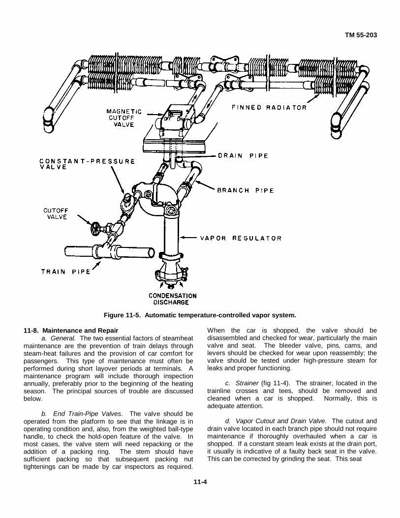
TM 55-203
Figure 11-5. Automatic temperature-controlled vapor system.
11-8. Maintenance and Repaira. General. The two essential factors of steamheat
maintenance are the prevention of train delays throughsteam-heat failures and the provision of car comfort forpassengers. This type of maintenance must often beperformed during short layover periods at terminals. Amaintenance program will include thorough inspectionannually, preferably prior to the beginning of the heatingseason. The principal sources of trouble are discussedbelow.
b. End Train-Pipe Valves. The valve should beoperated from the platform to see that the linkage is inoperating condition and, also, from the weighted ball-typehandle, to check the hold-open feature of the valve. Inmost cases, the valve stem will need repacking or theaddition of a packing ring. The stem should havesufficient packing so that subsequent packing nuttightenings can be made by car inspectors as required.
When the car is shopped, the valve should bedisassembled and checked for wear, particularly the mainvalve and seat. The bleeder valve, pins, cams, andlevers should be checked for wear upon reassembly; thevalve should be tested under high-pressure steam forleaks and proper functioning.
c. Strainer (fig 11-4). The strainer, located in thetrainline crosses and tees, should be removed andcleaned when a car is shopped. Normally, this isadequate attention.
d. Vapor Cutout and Drain Valve. The cutout anddrain valve located in each branch pipe should not requiremaintenance if thoroughly overhauled when a car isshopped. If a constant steam leak exists at the drain port,it usually is indicative of a faulty back seat in the valve.This can be corrected by grinding the seat. This seat
11-4

TM 55-203
should be tight when the valve is in open position.
e. Steam Couplers. If steam blows at the joint, itmay indicate broken lugs, faulty gasket, gasket spring, orlocking lever. Replace entire coupling only whennecessary.
f. Constant Pressure Valve (fig 11-5). This valveshould be removed and repaired annually usingprocedures as follows:
(1) Disassemble the valve, clean and inspectparts for wear.
(2) Replace any part showing excessive wearon any springs that have lost their tension.
(3) Inspect the diaphragm carefully,particularly at the edges where continual flexing occurs,as cracks develop in these areas.
(4) Check the needle valve assembly, assurethat the stem is true, and the valve and seat are notscored.
(5) Replace the needle valve if it or the valveseat are scored or wiredrawn.
(6) Reassemble, adjust, and test the constant-pressure valve under live steam pressure.
g. Vapor Regulator (fig 11-4). Visual observationof vapor regulators is sufficient to insure properfunctioning. Steam leaking through the regulator whenthe vapor valve is closed is an indication the valve is notseating properly. A worn valve seat or dirt between thevalve and seat may cause this condition. A worn seatshould be reground or replaced; dirt may be blown out byclosing the shutoff valve ahead of the regulator for a fewminutes, then opening it again. If steam blows from thedrain tube, the bellows diaphragm may be damaged.Before each heating season the regulator should betested under pressure. Assure that the operating rods arefree in the guide ruts. Thorough biennial overhaulincludes the following:
(1) Disassemble, clean, and inspect all partsfor wear.
(2) Replace badly worn or damaged parts.(3) Check spring tension and inspect the
gaskets.(4) Inspect the regulator valve, assembly,
bellows packing assembly, and the main bellows.(5) Reassemble the regulator and check on a
steam line.
h. Steam Traps. Excessive steam blows may beeliminated by changing the position of the adjustingscrew. A steam trap that cannot be properly adjusted
should be disassembled and inspected In the followingmanner:
(1) Remove the strainer and disassemble thetrap. Examine the spring seat, disk, diaphragm, andstrainer. Replace any defective parts.
(2) Test diaphragms before installation. Ifthe diaphragm is expanded too much, it will not return toits normal fully contracted form when cool. Place thediaphragm in a holding fixture and submerge in water atabout 190°F. Any leaks will be indicated by risingbubbles. A leaky diaphragm must be discarded; noattempt will be made to refill or repair it. After the test,submerge the diaphragm in cold water to contract it, thenremove it from the holding fixture.
(3) Reassemble the trap. Check to see theadjusting screw, pins, and cotters are in good condition.Test the trap on a steam line at about 55 psi. Regulatethe adjusting screw and observe for excessive steamblows.
i. Flow Limit Valve (fig 11-4). These valves shouldbe checked and repaired annually, prior to the heatingseason, using the following procedure:
(1) Disassemble the valve and inspect theinlet valve assembly.
(2) Thoroughly clean the inlet valveassembly, particularly the strainer. Assure that the stemis free and that the valve and seat are not seated or worn.
(3) If the inlet valve will not seat tightly,replace the inlet valve assembly and inspect the 'gasketunder the cap to see that the body of the flow limit valveis steamtight.
(4) Reassemble the valve and put it on alow-pressure steam line to determine the pressure atwhich the valve opens.
(5) If it does not open at the correct pressure,replace the spring.
j. Vapor Retarder (fig 11-4). A steam blow from theouter drain tube of a regulator indicates a faulty vaporretarder. Vapor retarders should be disassembled,cleaned, and inspected at least every 2 years, as follows:
(1) Test the thermostatic bellows for leaks byplacing it in a holding fixture and submerging in boilingwater. Do not submerge except in a fixture, as an over-expanded bellows will not return to its normally fullycontracted form. Leaks in the bellows will be indicated bybubbles rising In the water. Leaky bellows must bediscarded and replaced.
(2) Contract the bellows by submerging incold water. Reassemble the vapor retarder; assure thatthe cap is steamtight. If the retarder is fitted
11-5

TM 55-203
with a gasket under the cap, see that the gasket is in goodcondition and properly seated. Renew the gasket ifrequired.
k. Solenoid Steam Admission Valves (fig 114). It isessential that the wings and bodies be cleaned thoroughlywhen repairing the valve. The inside of the valve bodycan be cleaned without removing it from the car. Whenreassembling the valve, care must be exercised in thealinement of parts. With a thorough cleaning and properassembly, these valves should operate between shoppingperiods with little attention other than an occasional checkfor free operation. In some valves of the cutout type, thevalves controlling the floor-heat radiation normally areopen and are closed electrically as are the valvescontrolling steam to overhead radiators. Duringscheduled maintenance, the needle inlet valve should bereplaced if the seat is badly wiredrawn, or a sticking valvewill result.
l. Terminal Tests. Steam-heat equipment will betested in car yards to determine if in proper operatingcondition, prior to placing passenger type cars soequipped into train service. The following proceduresshould be followed:
(1) Place a "dummy" coupling on one end,and connect the car to the yard steam supply line at theother end.
(2) Place a steam pressure of 50 pounds onthe line.
(3) Check all shutoff valves and see that theyare open.
(4) Close all floor and overhead admissionvalves.
(5) Inspect all regulators to determine thatthey do not have a continuous steam blow.
(6) Inspect all conduits, end valves andbranch piping for leaks.
(7) Move admission valves to the "on"position; see that a complete heating circuit is made in allcoils.
(8) On vapor loop equipment, test the loopby closing all admission valves and checking all shutoffvalves to determine that they are in ,"open" position. Ifthere is a slight blow at the regulator, it indicates a faultyloop retarder. If a heavy steam blow is noted, it indicatesa bad valve or bellows in the regulator.
(9) Open each admission valve separatelyand check for a blow at the regulator. If a blow occurs, itindicates a faulty retarder or a dirty seat in that particularcoil.
11-6

TM 55-203CHAPTER 12
AIR CONDITIONING
12-1. GeneralThree types of air-conditioning systems have beendeveloped for use on railway passenger equipment: theice-activated, the steam-ejector, and the mechanical-compression types. In the ice-activated system, coolingis accomplished by bringing the air to be cooled in contactwith coils through which cold water is pumped.Mechanical refrigeration is not used in this system In thesteam-ejector system, water, the refrigerating system, isevaporated rapidly in a vacuum to produce the coolingeffect. Unevaporated water which is cooled as a result ofevaporation is circulated through the cooling coil. Thesesystems are largely obsolete, and only the mechanical-compression type is discussed in this manual (fig 12-1).Any military passenger equipment, such as ambulancecars, required to be air conditioned would be equippedwith this type of air-conditioning system. The SurgeonGeneral in the continental United States (CONUS) or thetheater surgeon in oversea areas would probablyprescribe conditions when excessive heat and humidityrequire air conditioning of rail equipment.
12-2. Mechanical-Compression SystemPractically all the mechanical-compression systems nowin use employ Freon (dichlorodifluoro-methane) as arefrigerant. The operation of the mechanical-compressionsystem is as follows: the refrigerant in a liquid state and athigh pressure in a receiver or storage reservoir is forcedby its pressure through an expansion valve. This valvecontrols the flow of the liquid-refrigerant from the high-pressure receiver to the air-cooling coil or refrigeratingevaporator where a lower pressure exists. Because of thereduction in pressure, a portion of the refrigerantevaporates, thereby lowering the temperature. The lowtemperature refrigerant in flowing through the air-coolingcoil absorbs heat from the air passing over the coil. Thisabsorption of heat vaporizes the refrigerant. Therefrigerant vapor flows to the suction side of therefrigerating compressor where it is compressed and itstemperature increased. The high-pressure, high-temperature refrigerant vapor is discharged from the
compressor into the refrigerating condenser, or heatexchanger, where heat is transferred from the refrigerantto the cooling medium passing over the condenser coils.The cooling medium is either outside air or a combinationof air and water. Thus, the refrigerant is condensed to aliquid state. The liquid refrigerant at high pressure flowsfrom the refrigerating condenser into the storagereservoir, after which the cycle is repeated. Diagram ofone kind of mechanical-compression system is shown infigure 12-1.
12-3. Control Equipment
a. General. Pneumatic-electric temperaturecontrol is based on the use of compressed air and electricmotors operated through accurately calibratedthermostats. The latter selects the proper coolness, heat,and humidity required by inside and outside conditions.Whether air conditioning depends upon a singlethermostat operating a damper motor or upon a moreelaborate system with compensated temperature andhumidity controls, the pneumatic-electric system can beused to control it.
b. Components. The system consists of thefollowing parts:
(1) A main thermostat, subject to changes intemperature inside the car.
(2) An inside or humidity compensator whichis exposed to the same temperature as the mainthermostat and an outside compensator which is exposedto the outdoor temperature in the air intake.
(3) A parking thermostat to controltemperatures when the car is in the yard.
(4) Damper and valve motors, controlled bythe main thermostat.
(5) A closed system of piping connected withthe compressed-air system of the train, supplemented bya storage cell of compressed air or by an air pump on theunderframe.
12-1

TM 55-203
Figure 12-1. Flow diagram for mechanical-compression system.
(6) A control panel with gages, switches,reducing valves, pilot lights, and other devices forchecking operation of the air conditioning when the car isin service and for checking replacements and repairswhen the car is out for maintenance. Most elaboratesystems use a series of thermostats, gaged to meet thevarying requirements of heating, cooling, and humidifyingthe air.
12-4. Maintenance and Repaira. General. A definite program of inspection and
maintenance is essential to the operation of air-conditioning equipment on railway passenger cars.Commercial railroads have found by experience thismaintenance program is divided into three generalcategories. The railroad designation and its militaryequivalent are: daily or end-of-trip maintenance(organizational), semimonthly (organizational-directsupport), and annual equipment overhaul (generalsupport-depot) In commercial railroad practice, this isflexible and is changed as necessary to meet therequirements of the particular service in which theequipment is placed. Maintenance procedures for variouscomponents are discussed below.
b. Condensing Unit. The coil assemblies should beinspected periodically and the framed surfaces cleanedwith compressed air. Accumulated cinders and dirtshould be cleaned from the framework. Supporting boltsshould be checked to assure they are drawn up tight, withthe nuts locked in place.
c. Compressor. Surface dust accumulations will beblown off with compressed air at the periodic inspections.An oily dirt accumulation indicates leaks which should belocated and corrected. All nuts will be tightened. Checkof compressor speed will indicate any belt slippage. Thecorrect compressor speed is 511 rpm for 6-ton equipmentand 382 rpm for 5-ton equipment. The correspondingmotor speeds are 1,750 rpm and 1,450 rpm respectively.Direction of rotation of the compressor is clockwise whenfacing the flywheel end.
d. Belt Adjustment. After loosening the motorsupporting bolts, adjust the belt tension by shifting themotor in its slotted supports by means of the adjusterscrews. When belt adjustment is necessary and until theinitial stretch is taken up, the fan shroud on the movableback half of the back cover should be moved with themotor so that the fan shift will always be centrally withinthe shroud. Proper belt tension will be
12-2

TM 55-203
obtained when a pressure of 10 to 15 pounds per belt,applied midway between the compressor and motorpulleys, will depress a single belt 1 inch. More sag thanthis shows too little tension and will cause belt slippageGreater tension increases belt stretch and shortenswearing life. The faces of the compressor and motorpulleys should be in alinement Check this after beltadjustments The face of the motor pulley must not projectout past the plane of the face of the compressor pulleyand should not be more than 1/16 inch behind this plane.
e. Lubrication. The compressor flywheel bearing iswick-fed lubricated from an oil reservoir in the crankcaseunder the bearing. This reservoir should be drained,flushed, and refilled monthly while air conditioning is inuse. Access to the reservoir is through oil filling plugs oneach side and in the bottom. The reservoir holds one-fourth inch and should be filled to the level of the fillinghole. All other lubricated surfaces are fed from the oilpump in the compressor crankcase. The crankcase holds12 pints of oil, filled to one-eighth inch from the top of thesight gage. The oil level must be checked after one-halfhour of normal operation and immediately upon shuttingoff the compressor. The accumulation of Freon in thecrankcase when the equipment is idle results in a fictitiousoil level indication. This may cause violet boiling of thecrankcase mixture when the pressure is reduced whilepumping down This result in oil being carried into thecylinder and pumped into the system, lowering the oillevel in the crankcase. The need for operating theequipment for some time before obtaining the true oillevel is obvious. Oil must be added when the observedtrue level is within 1/8 inch of the bottom of the sightgage.
f. Refilling Crankcase. To add oil to the crankcase,proceed as follows (compressor crankcase oil should bekept in, clean closed containers and not be left open tothe atmosphere any more than absolutely necessary):
(1) Place sufficient quantity of #24 or #25refrigerating machine oil in a clean container.
(2) Remove the plug from the oil chargingvalve on the side of the crankcase.
(3) Screw a short nipple into the plug holeand attach a clean rubber hose or copper tube to thenipple.
(4) Submerge the fuel end of the hose (ortube) well down into the oil in the container and open thevalve very slightly to purge the hose.
(5) Close the receiver shutoff valve andpump the system down until the low-pressure gage showsa slight vacuum.
(6) Open the oil filling valve slightly andpermit oil to enter.
(7) From observation of the true oil level,estimate the quantity of oil required to fill the level towithin 1/8 inch of the top of the sight gage and admit onlythis amount.
(8) If the true level cannot be determinedbecause of being below the sight gage, admit 2 pints at atime, operating the equipment after each addition until thelevel can be determined. Then proceed as outlinedabove, falling to the desired level.
(9) Close the oil filling valve and replace theplug in the valve outlet; open the receiver shutoff valve.
Caution: Never let the oil level in the containerfall below the mouth of the tube when adding oil, asthis would allow the compressor to suck in air.
g. Refrigerant Troubleshooting. The diagnosis oftrouble in the refrigerating system is a problem of causeand effect. The troubleshooter must have accurate gagesand thermometers, otherwise misleading reading will betaken. Care must be taken in handling Freon since it hasno odor and gives no warning of leaks. Car repairmenmust wear goggles when working on parts from whichrefrigerant may be liberated. If liquid refrigerant (Freon)gets into the eyes, the injured person should be rushed toa medical officer for attention. The following procedure isprescribed in the interest of safety:
(1) Open the compressor control switchbefore starting work around the electrical parts or rotatingparts.
(2) When the refrigerant vapor is pumpedfrom the compressor crankcase, follow the intermittentoperation to avoid pumping over excess amounts of oil,and building up of pressure in the crankcase. Thispressure is caused by the release of refrigerant dissolvedin the oil and results in blowing out of refrigerant vaporand oil when the crankcase is opened.
(3) Permit the evaporator unit to warm up toroom temperature before pumping down the refrigerant.This precludes escape of any liquid refrigerant left whenthe evaporator is disconnected.
(4) Check the oil level in the compressor afterreplacing major parts, which may contain
12-3

TM 55-203
oil, or after any change resulting in the loss of oil Addmore oil if required.
(5) Check that all shutoff valves are in openposition before starting equipment. This is particularlyapplicable to the compressor discharge shutoff valve, asthe compressor will be damaged if it is operated withthese valves closed.
(6) Service valves to be left open will beturned back slightly from the wide open position to insurethat they will not bind in the open, or back seated position.
(7) Purge all parts previously opened to theatmosphere to remove all air by releasing somerefrigerant.
(8) Check thoroughly for leaks at any pointwhere repairs have been made.
(9) Seal all valve connection plugs byapplying Clyptol to the slug threads. Do not apply it to thefemale threads.
(10) Use new gaskets when replacing partsrequiring gaskets. Be sure all parts are removed from thesurfaces before new gaskets are applied.
h. Winter Preparation. When the use of airconditioning equipment is discontinued for the wintermonths, the following precautions should be taken:
(1) Close the receiver shutoff valve and pumpthe refrigerant into the receiver, stopping the operation assoon as 5 pounds suction pressure is reached.
(2) Leave the crankcase with this positivepressure imposed to help prevent air and moisture frombeing drawn into the system at the shaft seal.
(3) Close the condenser shutoff valve, thecompressor suction cutoff valve, and the compressordischarge shutoff valve. Leave all other valves in normaloperating position.
(4) Remove the compressor driving belts,keeping each set intact and store them in a clean dryplace.
(5) Cover the unpainted surfaces of thecompressor flywheel pulley and motor pulley with rustpreventive.
(6) Remove the d.c. compressor motor fuse.(7) Place the narrow canvas belt provided
with the equipment over the fan openings in the middle ofthe motor. The ends of the belt should be at the bottomand the belt tied tightly around the motor.
(8) Place the canvas hood over the pulley andthe commutator end of the motor. The drawstring at theend of the hood will be at the outer end of the motorframe, while the drawstring placed through the ears ofextensions of the hood will be behind the rear row of pole
piece bolts. Both should be tied tightly in place.Enclosing covers of tin should be placed over thecondenser openings on both ends of the unit and thecondenser fan opening in the back cover of the unit.
(9) Shut off the air pressure to the spray watersupply tank where a separate tank is provided, and drainthe system. If separate water tanks are not provided,close the valve in the water line leaving the tank.
(10) Clean the strainers in the water line ofsediment and dirt.
(11) Open the petcocks in the spray nozzlepiping to drain all the water out, then close petcocks andblow down openings to prevent the entrance of dirt andforeign matter during the winter period.
i. Summer Preparation. Before operation of theair-conditioning equipment after the winter shutdownperiod, take the following actions:
(1) Remove all winter hoods and covers.(2) Inspect the apparatus for cleanliness and
blow out any dirt that may have collected.(3) Examine all bearings; add any lubrication
required.(4) Tighten all bolted joints in the wiring.(5) Inspect all contacts in the control for
proper condition.(6) Check brushes in the motor for freedom
and spring pressure.(7) Remove the slushing compounding from
the compressor flywheel and motor pulley and replace thebelts, keeping each set of belts intact. Check belt tensionand the proper alinement of pulleys.
(8) Loosen or remove both purge plugs, andnote whether or not any Freon is purged from thecompressor.
(9) Operate the compressor by hand to pull avacuum on the crankcase; then open the receiver shutoffvalve and the compressor suction shutoff valve. This willpermit Freon to flow from the receiver to the compressorcrankcase. Again rotate the compressor by hand to purgeany air that has leaked into the crankcase.
(10) Replace the purge plugs and open thecompressor discharge cutoff valves and condensershutoff valves. Check all valves for operating positioning,and replace the d.c. compressor motor fuse.
(11) Operate the equipment for a few minutesand check oil level in the compressor crankcase. Operatefor an hour making checks at intervals on refrigerant andoil levels.
(12) Check all joints for Freon leaks.
12-4

TM 55-203
PART FOUR
PAINTING, LETTERING, AND NUMBERING OF RAILWAY
CARS
CHAPTER 13
GENERAL
13-1. ColorsRailway equipment will be repainted only when requiredfor preservation purposes and not merely for the purposeof beautification or of changing color, unless considerednecessary for safety or security purposes by theresponsible commander. Except where otherwisespecified or directed, railway rolling stock in theaters ofoperations will be painted lusterless olive drab X34087. Inthe continental United States (CONUS), all exposedexterior painted surfaces on freight, passenger, hospital,kitchen, and caboose or guard cars, will be painted glossolive green 14064. All exposed exterior surfaces ongondola, hopper, and tank cars, will be painted glossblack 17038. All painting and marking will be inaccordance with AR 746-1, and paint standards containedin MIL-P-3320. For painting in theaters of operations, allexterior finish coats will be olive drab semigloss 24087. Acomplete list of paints authorized for use for railwayfreight and passenger cars is given in table 13-1.
Table 13-1. Authorized Materials
Material NumberAluminum gloss.........................17178Black, gloss...............................1703,8Black, semigloss .......................27038Black, lusterless ........................37038Blue, gloss ................................15044Blue, semigloss.........................25053Buff, gloss.................................10371Gray, gloss................................16187Gray, semigloss ........................26152, 26492, 26307Gray, lusterless .........................X14050, 14062, 14110Green, gloss..............................36118, 26270Green, semigloss ......................24410, 24260Olive drab, gloss .......................14087Olive drab, semigloss................24087Olive drab, lusterless.................34087
Table 13-1 Authorized Materials-Continued
Material NumberOlive green, gloss..................... 14064Red, gloss ................................ 11136White, gloss.............................. 17875White, semigloss ...................... 37875White, lusterless ....................... 13538Yellow, gloss............................. 33538Yellow, lusterless ...................... 33538
13-2. Safety
a. General. As a matter of Army policy, safetymarkings on railroad equipment will be applied in CONUSonly. Personnel engaged in painting operations must becautioned by supervisors to exercise caution in handlingpaints. Poisonous compounds are often used in paints.Personnel working with paints should wash hands andface carefully before handling food, and keep cuts orwounds free of painting materials. Many thinners createdangerous fumes, and personnel can be seriously injuredthrough inhalation. Most paint materials are flammable,and use of matches, open flames, or smoking should beavoided in paint areas.
b. Ventilation
(1) When painting the inside of anyequipment having only a small opening to the outer air,an air hose or electric blower will be used to force acontinuous flow of fresh air into the enclosed space. Twopersons will work together inside, while a third personremains outside near the opening to insure their safety.Personnel working on the interior will emerge at 15-minute intervals for fresh air.
(2) If it is at all practicable, cars will bepainted in the open air.
13-1

TM 55-203
c. Safety Precautions
(1) Respirators will be worn during all spraypainting operations.
(2) Preparations containing benzol will not beapplied by spraying Inhaling benzol fumes is extremelyinjurious to health.
(3) Cover lugs of the pressure-feed paint tankwill not be loosened unless it is certain that pressure inthe container has been released.
(4) Pressure-feed paint-tank safety valves willbe tested regularly.
(5) Rubber gloves should be worn when!handling sealer or acid solvents.
d. Causes and Prevention of Fire
(1) Fires in spray booths and other parts ofthe paint shop usually are the result of one of thefollowing causes: broken electric lamps and otherelectrical defects; cleaning of fans, motors, and interior ofbooths with highly flammable solvents; accumulateddeposits in booths, tubes, and vent pipes, resulting fromfailure to clean them frequently; defective fans andmotors used to ventilate the booths and paint shops;poorly designed and unguarded vent tubes; and staticelectricity.
(2) It is very important that the paint shop bekept clean Accumulated spray dust in booths and incracks and corners of the paint shop is particularlydangerous, because it ignites readily from spontaneouscombustion. All dust spray must be scraped from thewalls, spray booths, corners, and any other places inwhich it accumulates. Special nonsparking bronzescrapers will be used for this purpose. Before scrapingsare discarded, they must be soaked thoroughly with water.
(3) Flammable solvents are never used toclean the walls of the paint shop.
(4) Mist which comes from a spray gun ishighly flammable and a spark may ignite it. Smoking; theuse of open flame lights, space heaters, and processingequipment; the use of resistance-type electrical heaters;and the use of electric motors, switches, fuses, fuseboxes, and wiring not approved for use in atmospherecontaining flammable vapors, are prohibited in the plantshop.
(5) Only vapor-proof lamps will be usedwhere spraying is being done.
(6) Rags and waste which are soaked withpaint and oil are fire hazards, and will be placed instandard, self-closing metal cans having legs 'at least 4inches high to provide space for air circulation. Cans willbe emptied at the end of each working day and contentsremoved to a safe area for destruction. Trash andrubbish will be placed in covered metal containers whichwill be emptied daily and their contents destroyed orstored in a safety isolated vault.
(7) The main stock of solvents, paints, andother flammable materials will be stored outside the paintshop in a separate enclosure. Cans containing paints,thinners, and other paint materials will be covered tightlybefore being stored or put away for the night. Theprecautions outlined in TM 10-1101, for the storage ofpetroleum, will also be followed for paint, thinners, etc.
(8) Empty drums or other containers in whichsolvents, thinners, and similar other materials have beenshipped are potential hazards, since they often containenough vaporized material of a flammable nature tocause an explosion. Heat or flame must never be appliedto such drums or cans unless they are first steamed outthoroughly, filled with water, and Inspected to insure thatall traces of odor and of paint material are removed.
e. Protection While Sandblasting
(1) Operators will be equipped with propermasks, gloves, and canvas aprons to guard against injury.It will be the responsibility of the officer in charge to seethat these are provided and used.
(2) Sandblasting will not be performed inclosed areas unless adequate ventilation is provided, andadditional personnel are stationed outside to protect theworkers.
(3) Whenever possible, a shed or building atleast 100 feet away from any other shop building will beused for sandblasting. When it is necessary to sandblastin the open, the operation will be placed at a sufficientdistance to prevent sand, dust, or other particles fromgetting into nearby machinery or other equipment.
13-2
TM 55-203CHAPTER 14
PAINTING OF RAILWAY FREIGHT AND PASSENGER CARS
Section I. GENERAL14-1. Painting Policy
Railway freight and passenger cars normally will berepainted completely during depot maintenance. At othertimes, spot painting will be done as a matter of preventivemaintenance if the painted surface has deteriorated tosuch an extent that rusting or peeling is evident. Allrolling stock will be inspected periodically to locate anysurfaces on which paint has blistered, peeled, orotherwise deteriorated. Timely spot painting will insuresuitable protective coating on wood and metal surfaces,and often eliminate the need for complete repainting ofequipment The car repair shop supervisor will determinethe need for repainting, and whether to paint over oldsurfaces or remove old coatings. Exterior surfaces areexposed to rain, snow, sleet, hail, corrosive gases, heat,intense sunlight, wind-driven grit, and other destructiveinfluences. A good paint job depends upon weatherconditions, the selection of a suitable paint, properpreparation of the surface to be painted, and the methodof application. A film of sufficient thickness to cover andprotect the surface will be used.
14-2. Preparation for Painting
All surfaces will be cleaned of loose paint, dirt, scale,grease, and rust before they are painted. It is preferableto sandblast cars having steel exteriors or interior finishes,when the undercoats require renewing. This normally isdone in a sandblast shed (para 13-2e), where the oldcoatings are removed and a priming coat is appliedSandblasting of the thin inner sheets, such as are used forinterior finish on passenger equipment, may besatisfactorily accomplished with reduced air pressure, andwith sand that has been previously used on the heavyexterior sheets and has lost some of its sharpness Thesandblasting and priming of new sheets to be used in carrepairs frequently is done before the sheets are used.The manner in which either freight or passenger cars areprepared for painting depends upon the material of whichthe car is constructed, and upon the type of paint applied.
Freight cars usually are prepared by sandblasting,scraping, wire brushing, burning off old paint, or chemicalpaint stripping. Regardless of how the paint is removedand how the freight car is readied for painting, the firstcoat should be applied as soon after preparation aspossible. This prevents rusting on steel materials andwater-soaking of wooden materials involved. Onpassenger cars, the paint or varnish is removed whennecessary by paint or varnish remover. Paint is removedfrom the car body while the car is in the repair shop, andfrom trim in the shop where it is being reconditioned.Before being repainted or revarnished, the surfaces arecleaned with naphtha or similar material to remove alltraces of the remover. Fire and safety precautions will betaken when using naphtha.
14-3. Painting Techniques
a. General. Paint will be applied with care andunder competent supervision. For the protection of thesurface, the first or priming coat is of the greatestimportance, since corrosion or rot may spread rapidlyunder the paint film if the primer is not properly applied.
(1) Steel surfaces, other than welded or hot-riveted surfaces which are inaccessible after assembly,will be given one coat of chromate primer beforeassembly. Wood surfaces which are inaccessible afterassembly will be given one coat of synthetic primer beforeassembly.
(2) Wood or steel sills, braces, posts,stringers, etc., which are exposed during repairs toequipment, will be brush painted or sprayed with one coatof chromate primer.
(3) Paint applied to trucks and componentparts will be thinned sufficiently so that detection of cracksor other flaws is not prevented. Wheels, axles, and partscontained in the journal box will not be painted.
14-1

TM 55-203
b. Spray Gun Application. Hose of adequate insidediameter must be used with paint spray equipment. In agreat many instances, malfunction of the spray gun is dueto an insufficient supply of air at the gun. This conditionusually is caused by the use of hose of improper size. A
drop in pressure occurs whenever compressed air istransmitted. Table 14-1 Indicates the air pressure inpounds per square inch (psi) of a spray gun equipped withan air cap consuming approximately 12 cubic feet of airper minute at 60 pounds pressure.
Table 14-1. Spray Gun Air Pressures
Section II. FREIGHT CARS
14-4. General
a. Surfaces will be prepared for painting as outlinedin MILP-3320 (para 14-2).
b. All sections of new wood, except those to bevarnished, will be coated with wood preservative.
c. Parts exposed during repair parts inaccessibleafter assembly will be coated as outlined in paragraph 14-3.
d. Wheels, axles, couplers, and parts contained inthe journal box will not be painted.
e. On both all-steel and outside metal roofs, carewill be taken to cover with the required number of coatsall parts which are folded over or otherwise concealed.The finish coat on that portion of roof under the running
board is to be applied before running board saddles areinstalled. Running board saddles will receive one coat ofsynthetic primer and two coats of olive green enamelbefore being applied to cars.
f. When painting cabooses, measures will be takento prevent paint from damaging signal or brake valves,lights, gages, first-aid cabinets, firefighting equipment,hardware, door and window glasses, and lavatories.
14-5. Application of Materials
The type and number of primer and finish coats to beapplied to the various portions of freight cars andcabooses is shown in table 14-2.
14-2

TM 55-203
Table 14-2. Painting System for Freight Cars and Cabooses
14-3

TM 55-203Table 14-2. Painting System for Freight Cars and Cabooses-Continued
14-4

TM 55-203Table 14-2. Painting System for Freight Cars and Cabooses Continued
14-5
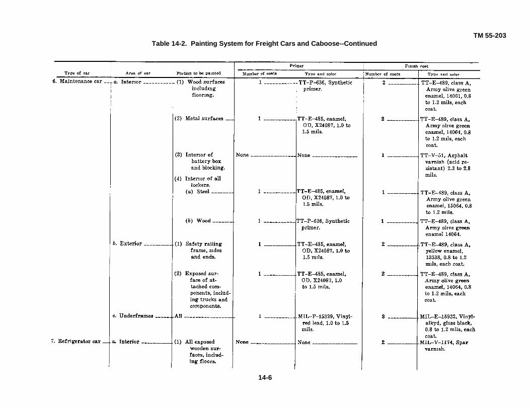
TM 55-203Table 14-2. Painting System for Freight Cars and Caboose--Continued
14-6

TM 55-203Table 14-2. Painting System for Freight Cars and Cabooses-Continued
14-7
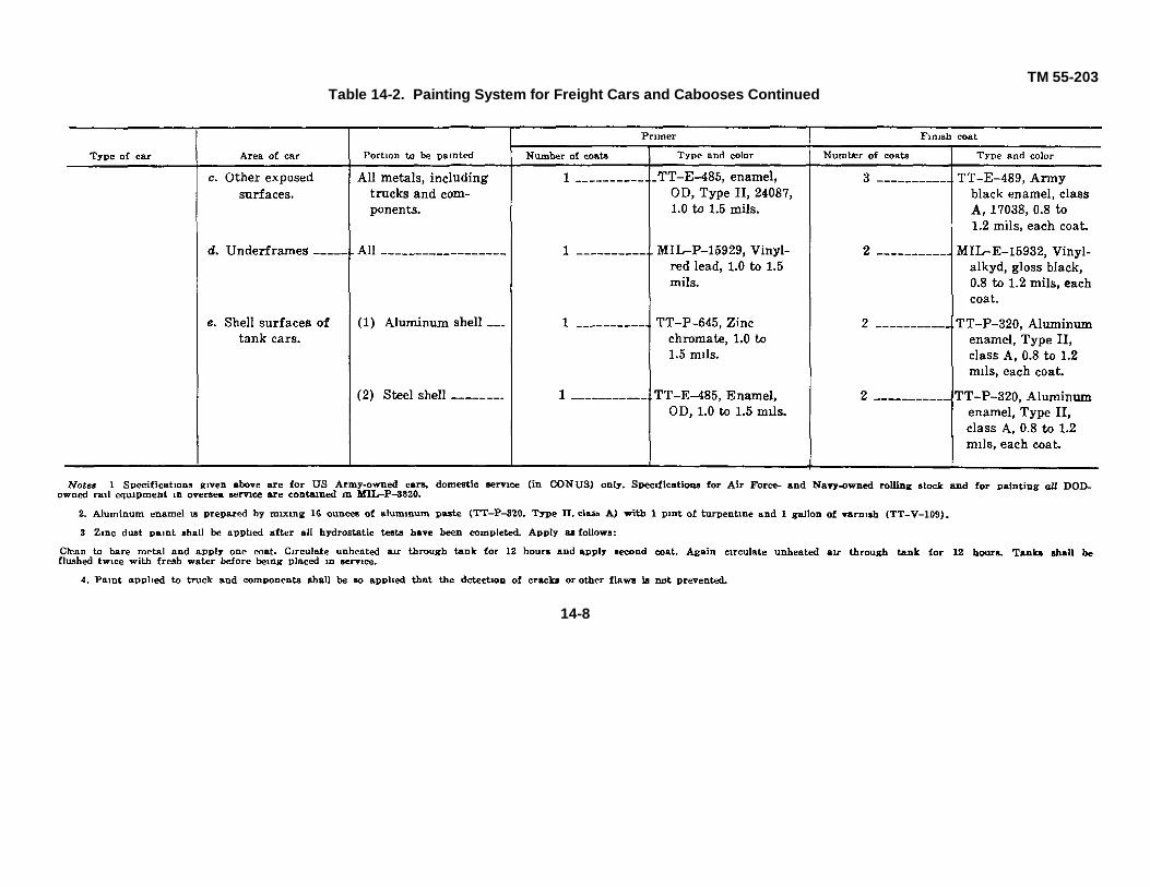
TM 55-203Table 14-2. Painting System for Freight Cars and Cabooses Continued
14-8

TM 55-203Section III. PASSENGER SERVICE CARS
14-6. GeneralPassenger, troop kitchen, guard, and Army MedicalDepartment cars (ambulance and hospital cars) requiremore careful attention to painting than freight cars, inorder to maintain standards of appearance, sanitation,and comfort. The precautionary measures indicated inparagraph 14-4 for freight cars and cabooses aregenerally applicable to passenger-type equipment, exceptthat in most cases additional care is required All glasssurfaces (windows, doors, etc.), screwheads, bearing andlubrication oilholes, rubber components, hinge pins, signalvalves, pressure gages, wheels, axles, journal box parts,
and all other surfaces or openings where paint may bedetrimental to operation or use, will be masked orotherwise suitably protected during painting. Safetymarkings will not be applied on railway equipment to beused outside the United States. All priming and finishcoats will be applied so that the work, when finished, willpresent a smooth, uniform coating with good adhesionover the entire surface. The various paints authorized foruse in painting passenger-type railway equipment arelisted in table 14-3. Passenger and Army MedicalDepartment cars will be painted and stenciled as providedin AR 746-1.
Table 14-3. Painting of Ambulance Cars
14-7. Application of MaterialsProtective coatings will be applied in thin, even coats.Particular care will be used to insure complete coverageof corners or other surfaces difficult of access. All bareand abraded spots in each coat will be touched up. Eachcoat will be completely dry before the succeeding coat isapplied. Each coat will be free from sags, blisters, brush
marks, evidence of poor adhesion, or other deficiencies.Surfaces will be dusted, and a tack rag will be used tofree them from dust before application of paint. Theprimer coat will be sanded lightly. Tables 14-3, 14-4, and14-5 show the type and number of primer and finish coatsto be applied to the various portions of passenger, troopkitchen, and ambulance cars.
Table 14-4. Painting of Kitchen Cars
14-9

TM 55-203Table 14-5. Painting of Troop Sleeper Cars
14-10

TM 55-203
CHAPTER 15
LETTERING AND NUMBERING OF RAILWAY FREIGHT
AND PASSENGER CARS
Section I. GENERAL
15-1. Purpose
The primary purpose of lettering and numbering is toidentify and classify equipment. Marking will be in clear-cut, properly located figures and will reflect the samehigh quality of workmanship as that in the equipmentitself. Distinction can be lent to an engineering designwith letters and numbers of neatness, strength, andquality that contribute to the general appearance of theequipment Even the roughest freight equipment will begiven the highest possible degree of perfection inbalance, proportion, and design of its markings. It isextremely important that letters and numbers be legibleand correctly placed, since they often must be copiedfrom the equipment by yard or train personnel at night,
and while the equipment is in motion.
15-2. Requirements
a. Lettering and numbering of Departmentof the Army (DA) railroad equipment will comply withrequirements of AR 55-255, AR 55-650, AR 746-1,Military Specification 3320, and MIL STD 129. Lettersand numbers illustrated in figure 15-1 are authorized forall Army-owned railroad equipment and will insureuniformity in identification and classification labels.Proportion has been analyzed mathematically andgeometrically in the drawings
Figure 15-1. Typical letters and numbers.
15-1

TM 55-203
b. Illustrations in this manual arepresented as typical of the various types of cars used bythe Department of the Army. Marking arrangementsmust be flexible to fit all types. On some cars, it will beimpossible to adhere strictly to size, arrangement, andlocation of markings as illustrated. Information infigures 15-2 to 15-6, as appropriate, will be shown in itsentirety on the cars in all cases. Information not shownon the drawings will not be added unless specificallyauthorized by the US Army Mobility EquipmentCommand. Markings on freight and passenger cars willbe arranged so as to present the same view from eitherside,
c. US Army and US Air Force-ownedfreight and passenger equipment meeting AAR andDOT specifications and required to operate on railroadsystems in the United States, Canada, and Mexico, willhave the reporting marks USAX or DAFX. US Navy-owned cars are marked USNX. All other equipment willhave the reporting marks USA, USN, or DAF.Department of Defense-owned cars of the interchangefleet are marked DODX. Military service-owned railequipment not marked with the letter "X" followingownership designation is restricted to interinstallationuse.
Section II. FREIGHT CARS
15-3. Boxcars, Flatcars, Gondola, Hopper,and Caboose (Guard) Cars in CONUS
a. White gloss enamel No. 17875 will beused for letters and numbers. All exposed exteriorpainted surfaces on boxcars, flatcars, and caboose(guard) cars will be painted gloss olive green No.14064. All exposed exterior painted surfaces ongondola, hopper, and Army-owned tank cars will bepainted gloss black No. 17038, as prescribed by AR746-1 Markings and lettering, including those on trucksand underframes, will conform to the applicableprovisions of the Manual of Standard andRecommended Practices, and to the AAR Code ofRules governing the condition of and repairs to freightand passenger cars. Army-owned cars which areacceptable to commercial railroads for interchange andwhich meet all requirements will be reported to the USArmy Mobility Equipment Command. These cars, whenauthorized, bear USAX and the car number.
b. Seven to nine-inch characters will beused and will be located to suit car construction (fig 1'5-2 to 15-6) Reporting marks on ends of the car, on trucks,and on purlins or the wall inside the car, will be 4-inchcharacters (fig 15-2 to 156). Letters and numbers willbe uniformly spaced. Weights will be shown as follows:
(1) The capacity (CAP) of the car will beshown in pounds to the nearest 1,000 pounds. Thiscapacity is the normal loading assigned to the car and isbased on the size of its axles.
(2) The load limit (LD LMT) is the actuallimitation on loading based on the difference betweenthe total weight on the rails permitted by the size of theaxle used and the lightweight of the car. When carscannot carry this maximum load, the actual loadingpermissible will be shown and a star will precede theload-limit marking. (3) The lightweight (LT WT) is the
actual scale lightweight of the car in multiples of 100pounds.
c. The full data carried on boxcars followsin d through i below. On all other types of cars, onlysuch dimensions as actually exist will be covered bythese markings. Dimensions indicating eaves width andheight (EW & H) are defined as follows:
(1) Eaves width is the outside width of a carat the top of the eaves (upper eaves if car is equippedwith Z-bar side plate), except on cars having a latitudinalrunning board extension, in which case, eaves measurefrom the outside edge of the top of the latitudinal runningboard to a corresponding point on the opposite side of thecar.
(2) Eaves height is the height from the topof the rails to the eaves (upper eaves if car is equippedwith Z-bar side plate), except on cars having latitudinalrunning board extension, where it is the height to the topof the latitudinal running board extension at the side ofthe car.
d. For all cars standing more than 12 feetfrom the top of the rail to the eaves, an additional set ofdimensions will be shown on the car. These will indicatethe car's extreme width and height (EXW & H).
(1) Extreme width is the measurementtaken from the attachment projecting to the greatestextent around eaves.
(2) Extreme height at extreme width is thedistance from the top of the rail to the point whereextreme width exists. e. Inside width, inside length, andinside height are represented as IW, IL, and IHrespectively. For all dimensions, fractions are omitted.For inside dimensions they are dropped,
15-2

TM 55-203
Figure 15-2. Standard markings for boxcars and refrigerator cars, CONUS.
Figure 15-3. Standard markings for gondola cars, CONUS.
15-3

TM 55-203
Figure 15-4. Standard markings for hopper cars, CONUS.
Figure 15-5. Standard markings for flatcars, CONUS.
15-4

TM 55-203
Figure 15-6. Standard markings for caboose cars, CONUS.
and for outside dimensions, the next full inch is used.Cubic capacity (CU FT) is the inside cubage; insidedimensions are used for computation. All abovemarkings (d and e) will be in 2-inch characters andspacing
f. On newly built cars, the NEW date with3 inch letters and numbers will be shown. When the carhas been rebuilt, the letters RBLT will be used and thedate indicated.
g. Airbrake cleaning data marking willinclude the place, month, day, and year of the lastairbrake cleaning. The reporting marks will be shown onthe auxiliary reservoir in 1 1/2-inch letters and numerals,with 1-inch spacing between lines. Stock will be one-fourth of an inch and bridges will be not more thanthree-sixteenths of an inch wide. If markings are notlocated to present a clear view from the outside of thecar, stenciling will be near the handle of the release rodon the reservoir side of the car (fig 8-19).
(1) The stenciling for periodic airbrakecleaning, etc., is of such importance that special caremust be taken to obtain in full detail the correct record ofold markings before they are removed. If the oldmarkings are indistinct due to grime, etc., they shouldbe carefully cleaned so that the correct information canbe ascertained, if possible.
(2) All old marks must be scraped off andpainted over with quick-drying paint (preferably black),which should be dry before new marks are applied
(3) The new marks must be correctlylocated as designated and must not be duplicated. Thisstencil must conform to the standard block type design(fig 1'5-1). The stencil must be kept clean, and themarks should be applied in a neat and exact manner.After the new marks have been applied, they should becarefully inspected to insure their correctness in alldetails.
h. Journal box repacking data for carsused in interchange must be in accordance with thecode of rules and conform to instructions contained inparagraph 4-14c. For cars not used in interchange, thedate and location of the last periodic jacking andrepacking will be shown; for example, RPKD-FE-1-6-72USAX.
i. On equipment owned and operated byDA, the words UNITED STATES ARMY in 7-inch letters,will be placed on both sides of cars in the locationindicated by figures 15-2 through 15-6.
15-4. Army Tank Cars in CONUS
a. White gloss enamel No. 17875 will beused for all letters, numbers, and insignia. Markings ontank cars are in more detail than markings on otherfreight cars because tank cars, for safety reasons, havebeen divided into several classes by Department ofTransportation (DOT) regulations. Each class is markedaccording to the type of commodity it is designed tohandle. These classifications will be followed in letteringand numbering tank cars which will be used ininterchange on commercial railroads.
b. Regulations referred to in a above willbe used in conjunction with instructions in this manual togovern the lettering and numbering of Army-owned newtank cars, new tank-car structures, new tanks forexisting car structures, and tank cars that have beenrepainted.
c. Tank cars that are acceptable forinterchange with commercial railroads will bear thereporting marks USAX (AR 746-1).
d. When tank cars are repainted andrestenciled, restenciling will be as illustrated in figure 15-7.
15-5

TM 55-203
Figure 15-7. Standard markings for tank cars, CONUS.
15-6
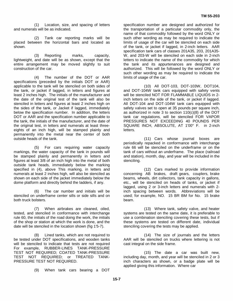
TM 55-203
(1) Location, size, and spacing of lettersand numerals will be as indicated.
(2) Tank car reporting marks will beplaced between the horizontal bars and located asshown.
(3) Reporting marks, capacity,lightweight, and date will be as shown, except that theentire arrangement may be moved slightly to suitconstruction of the car.
(4) The number of the DOT or AARspecifications (preceded by the initials DOT or AAR)applicable to the tank will be stenciled on both sides ofthe tank, or jacket if lagged, in letters and figures atleast 2 inches high. The initials of the manufacturer andthe date of the original test of the tank will also bestenciled in letters and figures at least 2 inches high onthe sides of the tank, or Jacket if lagged, immediatelybelow the specification number. In addition, the lettersDOT or AAR and the specification number applicable tothe tank, the initials of the manufacturer, and the date ofthe original test, in letters and numerals at least three-eights of an inch high, will be stamped plainly andpermanently into the metal near the center of bothoutside heads of the tank.
(5) For cars requiring water capacitymarkings, the water capacity of the tank in pounds willbe stamped plainly and permanently in letters andfigures at least 3/8 of an inch high into the metal of bothoutside tank heads, immediately below the markingspecified in (4), above This marking, in letters andnumerals at least 2 inches high, will also be stenciled asshown on each side of the jacket immediately below thedome platform and directly behind the ladders, if any.
(6) The car number and initials will bestenciled on underframe center sills or side sills and onboth truck bolsters.
(7) When airbrakes are cleaned, oiled,tested, and stenciled in conformance with interchangerule 60, the initials of the road doing the work, the initialsof the shop or station at which the work is done, and thedate will be stenciled in the location shown (fig 1'5-7).
(8) Lined tanks, which are not required tobe tested under DOT specifications, and wooden tankswill be stenciled to indicate that tests are not requiredFor example, RUBBER-LINES TANK-PRESSURETEST NOT REQUIRED; COATED TANK-PRESSURETEST NOT REQUIRED; or TREATED TANK-PRESSURE TEST NOT REQUIRED.
(9) When tank cars bearing a DOT
specification number are designed and authorized forthe transportation of a particular commodity only, thename of that commodity followed by the word ONLY orsuch other wording as may be required to indicate thelimits of usage of the car will be stenciled on each sideof the tank, or jacket if lagged, in 2-inch letters. AARspecification tank cars of classes 201A35, 203, 201A35-W, and 203-W will be stenciled on each side in 2-inchletters to indicate the name of the commodity for whichthe tank and its appurtenances are designed andauthorized. This will be followed by the word ONLY orsuch other wording as may be required to indicate thelimits of usage of the car.
(10) All DOT-103, DOT-103W, DOT104,and DOT-104W tank cars equipped with safety ventswill be stenciled NOT FOR FLAMMABLE LIQUIDS in 2-inch letters on the side of the tank, or jacket if lagged.All DOT-104 and DOT-104W tank cars equipped withsafety valves set to open at 35 pounds per square inch,as authorized in note 3 to section 110(c)(8) of the DOTtank car regulations, will be stenciled FOR VAPORPRESSURES NOT EXCEEDING 40 POUNDS PERSQUARE INCH, ABSOLUTE, AT 1'00° F. in 2-inchletters.
(11) Cars whose journal boxes areperiodically repacked in conformance with interchangerule 66 will be stenciled on the underframe or on thetank of cars without an underframe. The place (railroadand station), month, day, and year will be included in thestenciling.
(12) Cars marked to provide informationconcerning AB brakes, draft gears, couplers, brakebeams, wheels, dirt collectors, tank capacity in gallons,etc., will be stenciled on heads of tanks, or jacket iflagged, using 2 or 3-inch letters and numerals with 2-inch spacing between words. Abbreviations will beused; for example, NO. 15 BR BM for No. 15 brakebeam.
(13) Where tank, safety valve, and heatersystems are tested on the same date, it is preferable touse a combination stenciling covering these tests, but ifthese systems are tested on different date, individualstenciling covering the tests may be applied.
(14) The size of journals and the lettersAAR will be stenciled on trucks where lettering is notcast integral on the side frame.
(15) The date a car was built new,including day, month, and year will be stenciled in 2 or 3inch characters as shown, or a badge plate will beapplied giving this information. Where car
15-7

TM 55-203
structures and tanks have been built on separate dates,see AAR interchange rule 3, section s.
(16) On all cars used for the transportationof commodities classified as dangerous by DOTregulations, metal placard holders will be applied to bothsides of the car as near the center of the car aspossible, and to both ends in the location shown.
(17) In no event will the capacity asstenciled on the card exceed the load limit based on theaxle capacity.
(18) Tank cars of classes DOT--103,DOT-103W, DOT-104, and DOT-104W, withmanhole closures equipped with approved safeguardswhich make removal of closures from manhole openingspractically impossible while tank interior is subjected tovapor pressure of lading, will be stenciled on each sideof dome, or jacket if lagged. Stenciling will be in linewith ladders and in a color which contrasts with the colorof the dome Manhole closure identification marks asshown will be included in the stencil. For dimensions,see paragraph 20(h) of DOT103 specifications. Tankcars of classes ARA-II, ARA-III, ARA-IV, DOT-103,DOT-103W, DOT-104, and DOT-104W, built before theeffective date of these specifications, which now havemanhole closures equipped with the approvedsafeguards mentioned above, will be stenciled asrequired by DOT regulations on each side of the dome,or jacket if lagged, in line with the ladders. A colorwhich contrasts with the color of the dome will be used(DOT regulations).
(19) Brake lever diagram metal badgeplates will be attached (AAR interchange rule 3, section(b)).
e. On tank cars owned and operated by the Departmentof the Army, the words UNITED STATES ARMY in 7-inch letters, will be located 7 inches above the tophorizontal bar and centered above the reporting marksand car number (typical letters are shown In figure 15-1).
15-5. Boxcars, Flatcars, Gondolas, Caboose, andRefrigerator Cars in Theaters of Operations
a. White gloss enamel No. 17875 will beused for all insignia, letters, and numbers. Letters andnumbers will conform to figure 15-1. Boxcar andrefrigerator car markings are shown in figure 158, andgondola car markings are shown in figures 15-9 and 15-10. Markings on flatcars will conform to figures 15-10and 15-11 and will be restricted to the informationshown. Category numbers for European railcars
(used by STANAG countries) are illustrated in figure1512. Caboose markings are shown in figure 15-13.
b. The reporting marks USA and the carnumbers on the sides of the car will be 7-inchcharacters. Reporting marks on the ends of cars will be4-inch characters.
c. The capacity (CAP) and lightweight (LTWT) will be 2-inch characters. Load limit (LD LMT) willnot be shown.
d. Inside width (IW), inside length (IL), andinside height (IH), as applicable, will be shown in 2-inchcharacters. For all dimensions, fractions will bedropped.
e. Airbrake cleaning data marking will beshown in 1-inch characters. Only the month, day, andyear of the last airbrake cleaning will be shown.
f. Journal box repacking data (date only)will be shown in 1-inch characters (fig 15-2 to 15-6).
g. Foreign service flatcars destined forNATO countries shall be marked with category numbersin accordance with table L5-1. The category number (fig15-12) shall be displayed on both sides of the car andlocated as shown in note 2, figure 15-11.
Table 15-1. STANAG 2153 Category Numbers
Capacity (tons) Width of car Category number40 8' 7 1/4" None50 8' 7 1/4" None70Depressed center 9' 8" 580 9' 8" 5
15-6. Tank Cars, Theaters of Operations
a. White gloss enamel No. 17875 will beused for all letters, numbers, and insignia. Letters andnumbers will conform to figure 15-1. Markings willconform to figure 15-14 and will be restricted toinformation shown so far as practicable. Deviation willbe at the discretion of the headquarters of the militaryservice of the theater concerned.
b. Reporting marks USA and the carnumber on the sides of the car will be 7-inch characters.!Reporting marks on the ends of the car will be 4-lunchcharacters.
15-8

TM 55-203
Figure 15-8. Standard markings for boxcars and refrigerator cars, theatersof operations.
c. The capacity (CAP) in pounds to the nearest1,000 pounds will be shown in 2-inchcharacters on the sides of the tank.
d. The lightweight (LT WT) in pounds to thenearest 100 pounds will be shown In 2-inchcharacters on the sides of the tank.
e. The capacity of the tank in gallons will beshown in 2-inch characters on the ends of
the tank.
f. Airbrake cleaning data (date only) will beshown in 1-inch characters (fig 15-14).
g Journal box repacking data (date only) willbe shown in 1-inch characters.
15-9

TM 55-203
Figure 15-9. Standard markings for high-side gondola cars, theaters of operations.
15-10

TM 55-203
Figure 15-10. Standard markings for low-side gondola cars, theaters of operations.
15-11

TM 55-203
Figure 15-11. Standard markings for flatcars, theaters of operations.
15-12
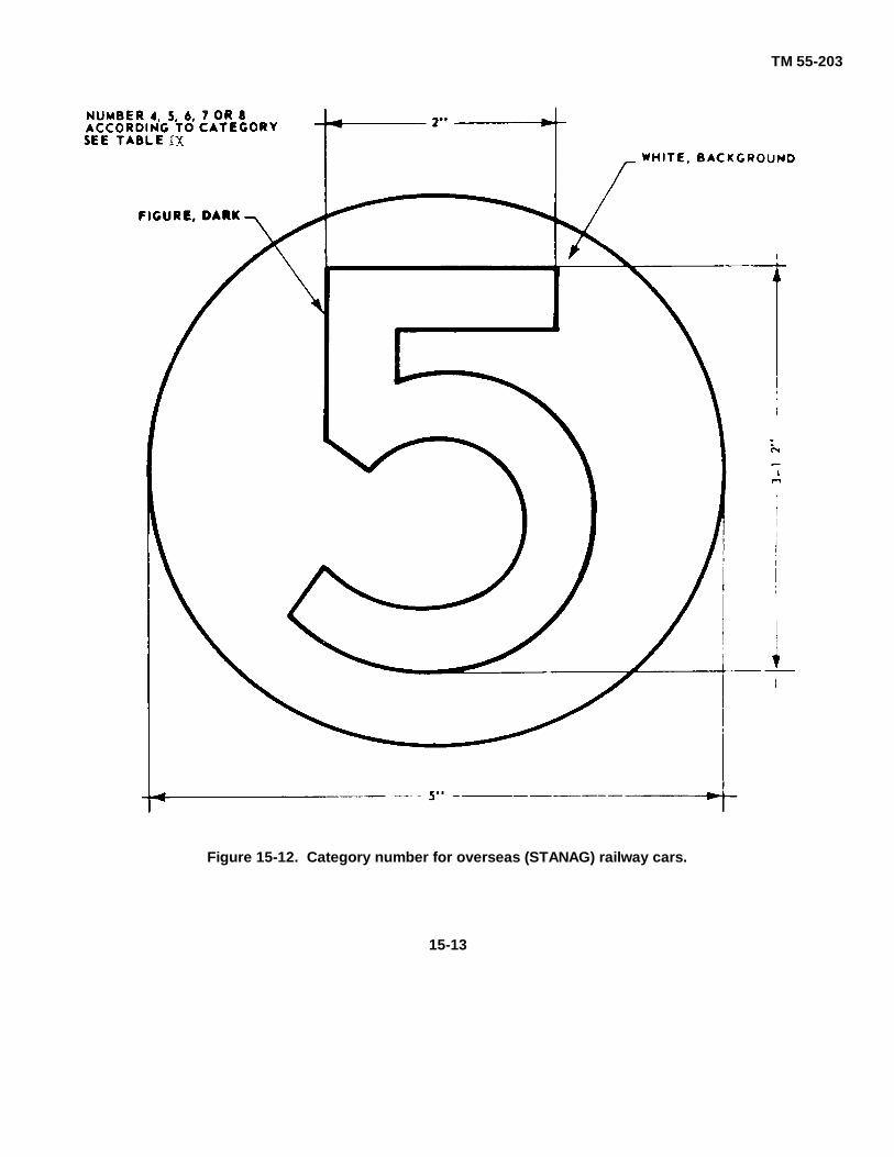
TM 55-203
Figure 15-12. Category number for overseas (STANAG) railway cars.
15-13

TM 55-203
Figure 15-13. Standard markings for caboose cars, theaters of operations.
Figure 15-14. Standard markings for tank care, theaters of operations.
15-14

TM 55-203
Section III. PASSENGER 'SERVICE CARS
15-7. Passenger Cars in CONUS
a. It is not practicable to present standardprocedures for lettering and numbering passengerequipment, since there is little use by the Department ofthe Army. However, the example illustrated in figure15-15 should be used as a guide in marking passengerequipment.
b. All letters, numbers and insignia will be
applied with white gloss enamel No. 17875, inaccordance with AR 746-5.
c. On equipment owned and operated byDA, the words UNITED STATES ARMY will be appliedin extended letters on the letter board on the side of thecar in 7 or 9-inch letters to suit
Figure 15-15. Standard markings for ambulance train cars.
15-15

TM 55-203
the width of the board, approximately in the positionshown in figure 1'5-15.
d. The car number, in 7-inch figures, will belocated below the belt rail, centered on the side panelabove each truck, and in 4-inch figures on the outside ofthe vestibule door at each end of the car.
e. Airbrake cleaning date will conform to theprovisions of interchange rule 60 for all cars used ininterchange. The place, month, day, and year of thelast airbrake cleaning and the reporting marks will beshown on the auxiliary reservoir in 1 1/2-inch characterswith 1-inch space between lines. If the marks are notlocated so as to present a clear view from the outside ofthe car, the stenciling will be placed near the handle ofthe release rod on the reservoir side of the car.
f. Journal box repacking data for cars used ininterchange must be in accordance with AAR passengercar interchange rule 7 (1) (1). For cars not used ininterchange, the date and location of the last periodicrepacking is sufficient.
g. Size and positioning of markings for troopkitchen cars will be as indicated in figure 15-16.
15-8. Passenger Cars and Troop Kitchen Cars,Theaters of Operations In theaters of operations,
passenger cars and troop kitchen cars ordinarily will bemarked as in the continental United States. Deviationsfrom markings illustrated in figures 15-15 and 15-16 willbe at the discretion of the headquarters, transportationrailway service, of the theater concerned.
15-9. Ambulance Cars, CONUS and Theaters ofOperations
a. General. When it becomes necessaryto renew lettering and numbering of ambulance cars,these markings will be restored as illustrated in figures15-17 and 15-18. No deviations will be made fromthese instructions except upon authority from the ArmyMedical Department through the US Army MobilityEquipment Command.
b. Letters, Numbers, and Insignia
(1) All letters and numbers will beapplied with white gloss enamel and will be of the styleshown in figure 15-1.
(2) The Red Cross insignia will be appliedwith red enamel on a white enamel field. The caduceus(fill 15-19) will be red enamel.
Figure 15-16. Standard markings for troop kitchen cars, CONUS and theatersof operations.
15-16

TM 55-203
Figure 15-17. Standard Army Medical Department markings for ambulance unitcars, CONUS and theaters of operations.
Figure 15-18. Standard Army Medical Department markings for ambulancekitchen cars, CONUS and theaters of operations.
15-17

TM 55-203
Figure 15-19. Caduceus, Army Medical Departmentinsignia.
(3) The words UNITED STATES ARMY will be inscribedon letter boards of all cars.
(4) All numbers, letters, and insignia will be applied asshown in figures 15-17 and 15-18. Sizes and positions ofmarkings will not be deviated from.
(5) Airbrake cleaning data will conform to provisions ofinterchange rule 60 for all cars used in interchange. Theplace, month, day, and year of the last airbrake cleaningand the reporting marks will be shown on the auxiliaryreservoir in 1 1/2-inch characters with 1-inch spacebetween lines. If marks are not located so as to presenta clear view from the outside of the car, the stencilingwill be near the handle of the release rod on thereservoir side of the car.
(6) Journal box repacking data (in accordance withpassenger car interchange rule 7(1) (1) will be locatedon each side of each truck at corners diagonallyopposite to each other where space permits; otherwise,It will be placed on the side of the car body at theplatform end sill or the step side on corners diagonallyopposite to each other. The day, the location, and therailroad marking of the last periodic packing andrepacking will be shown; for example, RPKD FE-1-6-72USAX.
15-18

TM 55-203
PART FIVE
INSPECTION AND MAINTENANCE
CHAPTER 16
GENERAL
16-1. Inspections
There are two general categories of inspections whichare performed on Army-owned rolling stock. One is theperiodic and required inspection performed atDepartment of Army installations by the agencies havingresponsibility for the equipment as part of themaintenance program. The other type of inspection isthat performed by railway inspectors. Anywhere thatArmy owned rolling stock is operated, in CONUS or inoversea areas, it will be subjected to such inspectionsSuch cars will be inspected when received from anArmy activity for movement, when delivered from onerail line to another at connecting line interchange points,and at the various yards and terminals through whichthey pass en route from origin to destination The detailsof inspections discussed herein are applicable to anytype of inspection that DA civilian or military carinspectors may be required to perform.
16-2. Maintenance
a. General. Inspection reports showing thecondition of worn or damaged parts requiring repair orreplacement, the extent of maintenance required, andthe record of work performed are responsibilities of theindividual installation car inspector. He assures byvisual examination that no defects exist which mightaffect the safe movement of a car and its contents. Theoverall responsibility for frequency of inspections andmaintenance policies and procedures is vested in theDepartment of Defense agency which controls,operates, or utilizes the railway rolling stock concerned.Various forms used by Army Inspectors are discussed inchapter 17. Reports required will be prepared incompliance with applicable AMC directives. In overseaareas, such reports will be prepared as directed by thetheater commander. TM 38-750, which contains generaldirectives and facsimile forms required In the Armymaintenance program, is not applicable to railway cars.Inspectors will check condition of Automatic CarIdentification (ACI) labels where applied to DOD-owned
cars in interchange service. ACI labels when originallyapplied will comply with AAR label application rules.
b. Cyclic Maintenance Inspection. Railwayrolling stock in storage will be inspected at statedintervals in accordance with the type of storage on thefollowing schedule:
(1) Limited storage, 6 months or less.Items placed in limited storage will be inspectedevery 90 days.
(2) Standby storage, 6 to 12 months.Items placed in standby storage will be inspected every90 days.
(3) Long-term storage, over 12 months.These items will be inspected as follows:
(a) Items not stored underdehumidification, every 90 days.
(b) Items stored underdehumidification, annually. These items will havehumidity readings taken each week and recorded.
c. Protective Maintenance Procedures.The procedures for maintenance and preservation ofstored railway rolling stock, both freight and passengerequipment, are outlined in detail for the three categoriesof storage Just discussed in DA Technical Bulletin TC14. In both limited and standby storage, car journals willbe preserved by moving the equipment approximately100 feet each month. Airbrakes will be preserved byoperating or actuating the brakes four or five timesduring each monthly exercising. In long-term storage ofcars not dehumidlfled, Journals will be preserved byremoval of packing waste and lubricating oil, repackingwith new waste, and saturation of journal boxes withprescribed pre-
16-1

TM 55-203
servative oil (Type P-10, Grade 2). These cars will alsobe moved 100 feet or so monthly to distribute thepreservative over the journals. Airbrakes also will beoperated during this exercising as prescribed above.
16-3. Inspection Points
a. General. Railway cars are inspected atvarious places for different reasons. In normal railwaypractice, commercial or military-owned cars areinspected at terminals and classification yards whenthey arrive (in trains); when made up into trains forforwarding to the next yard; at interchange points whenreceived from another railway; at loading points; and, atvarious repair or shop tracks On the railways of NorthAmerica, Western Europe, or other areas where carsmove freely between different rail lines and differentcountries, interchange inspection constitutes animportant detail of through traffic movement. Thetechniques of car inspection and the various inspectionobjectives are discussed in the following paragraphs.The primary purpose of inspecting railway cars, likeinspections of any item, is to determine the condition,suitability for service, extent of any needed repairs, etcCar inspectors should be technically qualified andshould be equipped with inspector's hammer, reflectorlamp (for night use), and packing hook. The specificgeneral reasons for inspections at the various placeslisted in this paragraph are discussed below.
b. Receiving and Classification Yards.Cars are inspected on arrival for defects requiringimmediate attention. Inspection includes draft andrunning gear and, if the car is loaded, inspection forleaking and for poorly secured or shifted lading. Carsrequiring maintenance that cannot be completed on timefor the movement of the train will be tagged "bad order"(para 17-10), cut out, and sent to a repair track fornecessary servicing. After trains are made up, cars areagain inspected to insure that they are in good conditionbefore departure. This involves the inspection andtesting of airbrakes, a thorough examination of journalboxes, and the detection of other possible defectsdeveloped during yard switching operations.
c. Loading Points. At loading points suchas freight stations, industrial plants, military installations,etc., cars are inspected to insure the suitability of the carfor the proposed lading; that all loading rules are (orwere) properly observed; and that the lading is loaded,blocked, braced, or secured for safe movement.
d Interchange Points. Cars to be receivedfrom connecting lines are inspected to see that theyconform to proper interchange loading and 'safetyappliance rules (AAR and DOT in CONUS) and that
they are in good mechanical condition. This Inspectionprecludes the receiving railway from acceptingresponsibility for defective equipment and/or damagedlading that occurred elsewhere.
e. Repair or Shop Tracks. The inspectionof cars on repair or shop tracks involves a careful andthorough examination of all car details to determine theextent of repairs necessary. The kind and quantity ofrepair material required and the disposition of car forrepairs largely depend on the results of these repairtrack inspections At railway shops and repair tracks, theclass of repairs is determined by the number of man-hours required to make the repairs. Unlike the Armysystem, commercial railway repairs are designated light,medium, or heavy as follows:
(1) Light repairs: labor under 20 hours.
(2) Medium repairs: labor 2.0 hours to 50hours.
(3) Heavy rep-airs: labor 50 hours orover.
16-4. Inspection Procedures-Freight Cars
a. General. In classification yards andterminals, two car inspectors (one on either side) shouldmeet each incoming train for a general visual inspectionof the cars as they roll into the yard. Military installationinspectors should make similar inspections as drafts ofcars are brought onto the installation from the deliveringrailway interchange track. Wheels that are pounding(flat spots) or wobbly, or that have broken flanges, canbe spotted as the cars move slowly past the inspectors.Leaking air lines, low or dragging brake rigging,brakeshoes riding wheels, etc, will be readily visibleThese defects are more difficult to detect when cars arestanding still. The train, or draft of cars, should bestretched when it is stopped with airbrakes applied toenable inspectors to more readily detect excessivepiston travel, weak draft gears, broken yokes and yokerivets, worn knuckle locks, wornout draft sills, shortbrake pipes, defective hose and coupler defects, brokentruck frames, etc. Careful inspection will be made ofeach car in the draft or train after they are stopped. Anydefects found will be corrected before the car is movedin another train, or car is loaded (if
16-2

TM 55-203
empty), etc., as applicable. Flame torches will not beused in inspecting cars. Only electric, gas, or kerosenelamps, with glass reflectors, are authorized. Theprocedures next discussed are applicable to all types ofcars; items pertinent to specific types of cars arediscussed separately. (These same procedures areapplicable to the periodic maintenance inspections ofmilitary owned rolling stock made by Army maintenancepersonnel.)
b. General Inspections. Car inspector willcheck over all cars just received in the yard orinstallation as follows:
(1) Couplers. Inspect knuckle, knucklepin, coupler body, and carrying iron for cracks, wear, orother defects. Height should be checked with couplergage, or in relation to another coupler.
(2) Draft gears. Check for broken ormissing cross keys, cotter keys, loose or broken rivets,broken draft spring.
(3) Safety appliances. Check condition ofbrake wheels, brake chains, grab irons, ladders, brakesteps, etc.
(4) Underframes. Inspect for bent,broken, or loose body bolster center plates and brokenor missing side bearings Check sills for cracks -orbrakes. Tap nuts and rivets with hammer.
(5) Car trucks. Inspect for cracked orbroken side frames, missing or broken bolster springs,broken brake lever brackets, damaged center castingsor center pins; inspect brake rigging for wornbrakeshoes (replace 1/2 inch or less thick) broken brakehangers, brake rods, missing brake lever pins, or cotterkeys.
(6) Car wheels. Inspect wheels for slidflats; shelled spots; brake burns; cracked, broken, orworn flanges; broken rims; bent axles; wheels loose onaxle, etc.
(7) Journal boxes Inspect journals byraising the box lid and, through visual inspection and byuse of the packing hook, assure that journal bearingsand wedges are in good condition and in place, that thepacking is placed properly against the journal, and thatthere is sufficient oil.
(8) Superstructure. Inspect end and sideladders, corner and end posts, brake shaft, siding,striking castings, uncoupling levers, etc.
(9) Tightness check. Tap all nuts withinspector's hammer to check for tightness.
c. Closed Cars. Car doors of box and
refrigerator cars will be inspected for the following:(1) Assure doors open and close without
jamming or difficulty, and that when closed, they areweathertight and capable of being secured againstpilferage.
(2) Roofs and sides do not leak.
(3) Insides will be inspected to determinefor which ladings the car is not suitable (e.g, flour orsugar should not be placed in a leaky boxcar).
(4) Doors, hatches, and other openings ofrefrigerator cars will be inspected to insure tightness tofit; floors, roofs, and walls will be checked for air orwater leaks. Bunkers will be examined for leaks.
(5) Heating, ventilating, and refrigeratingequipment and appliances will be inspected formalfunctions or defects.
d. Open-Top Cars. The completeinspection of these cars includes the additional itemspeculiar to the type of car. These items include stakepockets on flatcars, end gates, bottom and side doors (ifprovided) on gondolas; hopper mechanism, drop-bottomdoors, etc., on hopper cars, and pneumatic equipmenton dump cars.
e. Tank Cars. When inspected underload, all parts of the cistern will be examined for leaksand discharge valve checked to see that it is watertight.Leaky tank cars "will be repaired before furthermovement, or the load transferred to another car.Inspections will include dome covers, dome valves, andheater coils (if used).
16-5. Inspection Procedures--Passenger Carsa. General The inspection of passenger
equipment is similar in many respects to freight cars.The inspection of couplers, draft gear, underframes,trucks, and wheels generally are the same. Sincepassenger cars carry human cargo, inspections must becomplete and thorough and include other items peculiarto passenger equipment such as steam lines, steamhose connections, signal lines, signal valves,generators, batteries, motors, refrigerating equipment,water pipes, and the various heat, light, water and airconditioning controls.
b. General Inspections. In addition to theinspections prescribed in paragraph 16-4 for freight cars,the following items found only on passenger equipmentwill be inspected when passenger trains arrive atterminals where inspectors are located or whenpassenger cars are assembled to make up a train.
16-3

TM 55-203
(1) Doors and windows. Doors should beinspected for proper operation, to insure that doorchecks and latches function, etc. Doors and windowswill be checked for broken glass.
(2) Heating and lights. Heat and lightswitches, lights, heat valves, blowers, fans, pumps,compressors, thermostats, etc , will be inspected forproper functioning.
(3) Superstructure. Superstructureinspection includes roofs, sides, corner and vestibuleposts, steps, handholds, ladders, marker brackets,trainline, air signal and steam heat fittings, buffers,diaphragms, gates, etc.
(4) Trucks. Elliptic springs, equalizersprings, and other parts not found on freight car truckswill be inspected for wear, damage, and properfunctioning.
(5) Interiors. Interiors should beinspected for condition of baggage racks, seats,washroom facilities, etc.
166. Terminal Testsa. General. As a general policy, trains will
not depart from dispatching points where car repairs and
materials are available for repairs unless all airbrakesare in good order and working properly. Cars found withinoperative airbrakes that cannot be quickly repaired willbe cut out, tagged (para 16-4), and sent to shop tracks.Rolling stock which is not equipped with airbrakes, buthas efficient handbrakes, handholds, steps, etc., can behandled, provided not more than 1'5 percent of therolling stock in any train will be handbraked. Theremaining 85 percent must be power braked withoperative airbrake equipment.
b. Preparation for Movement. Cars,derricks, steam cranes, and shovels and similar rollingstock which are not equipped with airbrakes, will befitted with a temporary 1 1/4-inch brake pipe with a 11/4-inch angle cock and standard air hose on each end.At each angle fitting, a standard shipping tag will beplaced indicating the date and place where the pipe wasapplied. Handbraked equipment, fitted as indicated, willnot be placed next to the locomotive, but may be placedanywhere else in the train. When more than one car orpiece of equipment is to be handled, they will bescattered throughout the train but always between carswith operating airbrakes The tender of a steamlocomotive will be counted as one car table 16-1 liststhe number of cars that may have inoperative airbrakesin trains of varying lengths.
Table 16-1. Maximum Number of Cars with Inoperative AirbrakesMaximum number of ears with
Number of cars in train Inoperative airbrakes6 or less ........................................................................................... 07 to 13 .............................................................................................. 114 to 19............................................................................................. 220 to 26............................................................................................. 327 to 33............................................................................................. 434 to 39 ............................................................................................ 540 to 46............................................................................................. 647 to 53............................................................................................. 754 to 59 ............................................................................................ 860 to 66............................................................................................. 967 to 73............................................................................................. 1074 to 79 ............................................................................................ 1180 to 86............................................................................................. 1287 to 93............................................................................................. 1394 to 99............................................................................................. 14100 to 106......................................................................................... 15107 to 113 ........................................................................................ 16114 to 119......................................................................................... 17120 to 126......................................................................................... 18127 to 133......................................................................................... 19134 to 139......................................................................................... 20140 to 146......................................................................................... 21
c. Terminal Train Brake Tests (1) The train must becharged to the required pressure. (Air pressureregulating devices on freight locomotives and cars mustbe adjusted for the following standard pressures: brake
pipe, 80 pounds main reservoir, 140 pounds ) Retainingvalves and retaining-valve 'pipes on freight cars must beinspected and
16-4
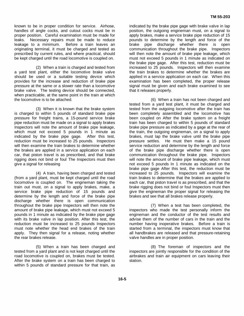
TM 55-203
known to be in proper condition for service. Airhose,handles of angle cocks, and cutout cocks must be inproper position. Careful examination must be made forleaks. Necessary repairs must be made to reduceleakage to a minimum. Before a train leaves anoriginating terminal, it must be charged and tested asprescribed by current rules, and where practical, shouldbe kept charged until the road locomotive is coupled on.
(2) When a train is charged and tested froma yard test plant, either the locomotive brake valveshould be used or a suitable testing device whichprovides for the increase and reduction of brake pipepressure at the same or a slower rate than a locomotivebrake valve. The testing device should be connected,when practicable, at the same point in the train at whichthe locomotive is to be attached.
(3) When it is known that the brake systemis charged to within 5 pounds of standard brake pipepressure for freight trains, a 15-pound service brakepipe reduction must be made on a signal to apply brakesInspectors will note the amount of brake pipe leakage,which must not exceed 5 pounds in 1 minute asindicated by the brake pipe gage. After this test,reduction must be increased to 25 pounds. Inspectorswill then examine the train brakes to determine whetherthe brakes are applied in a service application on eachcar, that piston travel is as prescribed, and that brakerigging does not bind or foul The Inspectors must thengive a signal for releasing
(4) A train, having been charged and tested(from a yard plant, must be kept charged until the roadlocomotive is coupled on. The engineman taking thetrain out must, on a signal to apply brakes, make, aservice brake pipe reduction of 15 pounds anddetermine by the length and force of the brake pipedischarge whether there is open communicationthroughout the brake pipe Inspectors will then note theamount of brake pipe leakage, which must not exceed 5pounds in 1 minute as indicated by the brake pipe gagewith its brake valve in lap position. After this test, thereduction must be increased to 25 pounds Inspectorsmust note whether the head end brakes of the trainapply. They then signal for a release, noting whetherthe rear brakes release.
(5) When a train has been charged andtested from a yard plant and is not kept charged until theroad locomotive is coupled on, brakes must be tested.After the brake system on a train has been charged towithin 5 pounds of standard pressure for that train, as
indicated by the brake pipe gage with brake valve in lapposition, the outgoing engineman must, on a signal toapply brakes, make a service brake pipe reduction of 15pounds to determine by the length and force of thebrake pipe discharge whether there is opencommunication throughout the brake pipe. Inspectorswill then note the amount of brake pipe leakage, whichmust not exceed 5 pounds in 1 minute as indicated onthe brake pipe gage. After this test, reduction must beincreased to 25 pounds. Inspectors will then examinethe train brakes to determine whether the brakes areapplied in a service application on each car. When thisexamination has been completed, the proper releasesignal must be given and each brake examined to seethat it releases properly.
(6) When a train has not been charged andtested from a yard test plant, it must be charged andtested from the outgoing locomotive after the train hasbeen completely assembled and the locomotive hasbeen coupled on After the brake system on a freighttrain has been charged to within 5 pounds of standardbrake pipe pressure as indicated by a gage at the rear ofthe train, the outgoing engineman, on a signal to applybrakes, must lap the brake valve until the brake pipepressure settles. He must then make a 15 poundservice reduction and determine by the length and forceof the brake pipe discharge whether there is opencommunication throughout the brake pipe. Inspectorswill note the amount of brake pipe leakage, which mustnot exceed 5 pounds In 1 minute as indicated on thebrake pipe gage After this test, the reduction must beincreased to 25 pounds. Inspectors will examine thetrain brakes to determine that the brakes are applied toeach car, that piston travel is as prescribed, and that thebrake rigging does not bind or foul Inspectors must thengive the engineman the proper signal for releasing thebrakes and see that all brakes release properly.
(7) When a test has been completed, theinspectors who made the test personally inform theengineman and the conductor of the test results andadvise them of the number of cars in the train and thenumber having inoperative brakes. Before a train isstarted from a terminal, the inspectors must know thatall handbrakes are released and that pressure-retainingvalve handles are in proper position.
(8) The foreman of inspectors and theinspectors are jointly responsible for the condition of theairbrakes and train air equipment on cars leaving theirstation.
16-5

TM 55-203
d. Road Train Brake Tests (1) At the point where motive power
or engine crew or train crew is changed, tests must bemade of the train brake system. After the brake systemon a freight train has been charged to within not lessthan 5 pounds below the standard brake pipe gage withthe brake valve in lap position, the engineman mustmake a 15-pound service reduction upon proper requestor signal and note the amount of brake pipe leakage asindicated by the brake pipe gage (which must notexceed 5 pounds per minute). After this test, thereduction must be increased to 25 pounds. Then, anexamination of the train brakes must be made todetermine whether brakes apply in a service applicationon each car. When this examination has beencompleted, the proper release signal must be given andeach brake must be examined to see that it releasesproperly.
(2) On a freight train, before a locomotiveis detached or an angle cock is closed on a locomotiveor car, the train brakes must be applied with a fullservice brake application. After recoupling, opening theangle cocks, and releasing the train brakes, but beforeproceeding, a 25 pound service reduction must bemade. Inspectors will note whether the rear brakes ofthe train apply and then signal for a release, notingwhether rear brakes release.
(3) When a locomotive or locomotives are,added to a freight train, after coupling on and openingthe angle cocks, but before proceeding, a 25-poundservice reduction must be made Inspectors will notewhether brakes on the cars at the rear of the train applyand then signal for a release, noting whether the rearbrakes release.
e. Airbrakes Tests on Arriving Trains.Freight trains arriving at terminals where facilities areavailable for immediate brake inspection and repairsshall be left with airbrakes applied with a total servicebrake pipe reduction of at least 10 pounds. Trainmenmust close the angle cocks on the head and rear carsbefore cutting off the locomotive or caboose. Inspectionof brakes and needed repairs must be made as soonthereafter as practicable. Where inspectors areemployed to make a general inspection of cars uponarrival at a terminal, they must make a visual inspectionof retaining valves, release valves and rods, retaining-valve pipes, brake rigging, handbrakes, hose, and theposition of angle cocks, and make necessary repairs ormark for repair tracks any cars to which repairs cannotbe made promptly.
16-7. Periodic Repairsa. Airbrake equipment on railway cars
must be cleaned, repaired, lubricated, and tested asoften as required to maintain it in a safe and suitablecondition for service, but not less frequently than as
prescribed below.(1) Freight cars:
(a) AB type brake, including ABtype brake cylinders, 48 months as indicated bystenciled date on car.
(b) Other brake equipment, 15months.
(c) When a freight car having brakeequipment not due for periodic attention as indicated byairbrake cleaning stencil is on shop or repair track, brakeequipment must be tested by single car testing device(fig 8-41) as prescribed by currently effective AAR Codeof Tests, providing such car has not been so testedwithin the previous 90 days as indicated by airbrakecleaning or in-date testing stenciling on the car. Propermethod of stenciling is illustrated in figure 819.
(2) Passenger cars:(a) D-22 type brake, 24 months.
(b) UC-type brake, 15 months.
(c) All other types, 12 months.
b. Missing pipe clamps must be replaced,and loose ones must be tightened. Hose and anglecocks must be properly positioned. Piston travel mustbe adjusted If required.
c. Handbrakes and connections must beinspected, lubricated, and tested and necessary repairsmade to insure that they are in suitable condition forsafe and effective operation.
d. Complete AB type freight car brake equipmentand high-speed passenger car brake equipment must becleaned, repaired, lubricated as required, and tested asprescribed by manufacturer's instruction pamphletsavailable through the US Army Mobility EquipmentCommand, St. Louis, Mo.
e. Brake cylinders other than the AB typemust be cleaned, repaired, lubricated as required, andtested as prescribed below.
(1) Brakes must be made inoperativebefore work is done on brake cylinders. This isaccomplished by closing the cutout cocks in the brakepipe branch pipes and draining all reservoirs. Whencutout cocks are provided in the brake cylinder pipes,only these cutout cocks must be closed. The reservoirsneed not be drained.
(2) Piston rods must first be secured tononpressure cylinder heads, after which nonpres-
16-6

TM 55-203
sure heads, piston rod, piston heads, and releasesprings must be removed and thoroughly cleaned byscraping off all deposits of grease and dirt and byremoving rust spots from piston rods and cylinder wallsusing sandpaper preferably, or emery cloth, if necessaryGrease and dirt must also be removed from leakagegrooves. All parts must be thoroughly cleaned (withcleaning solution, if necessary) and must be dried with acloth before being reassembled.
(3) Excessively worn piston packing cupsmust be renewed. Packing cups slightly worn at 'onelocation but otherwise in good condition may be used byrotating cups so that the worn side is at the top of thecylinder. Packing cups must be applied centrally onpiston heads. Follower studs in piston heads of otherthan U-type brake cylinders must be tight, and nuts mustbe tightened uniformly.
(4) The inner walls of cylinders and thebearing surfaces of piston packing cups must [have athin coating of approved brake cylinder ,lubricantapplied with a brush The grease groove of the pistonlubricator swab must also be filled with this lubricant
(5) Sharp tools must not be used in inserting piston assemblies in cylinders After pistonassemblies have been inserted in cylinders, but beforenonpressure heads are applied, piston rods must berotated slightly to avoid damage to packing cups and todetermine that assemblies are free and do not bind.
(6) After brake cylinders have beenreassembled on cars, a leakage test must be made,strictly in accordance with the approved, currentlyeffective, single-car code of tests.
f. Miscellaneous inspections and repairsinclude the following:
(1) Brake pipe, branch pipe, and pipe'bracket must be thoroughly blown out, and the strainerin the branch pipe, triple valve, or control valve must becleaned The dirt collector must be thoroughly cleanedby removing the bowl or plug. Before the plug or flangebolts are reapplied, threaded portions must be coatedwith oil and graphite or graphite grease. The dirtcollector must be applied in a vertical position with thebowl at the bottom.
(2) Should any of the triple-valve orcontrol-valve bushings require renewing, such workmust be done in the airbrake shop.
(3) Standard gaskets must be usedGaskets of irregular thickness or those having improperregistry of ports must be rejected.
(4) Slack adjusters, other than an air-operated type, must be adjusted to provide piston travelstandard to the car, see (9) and k below.
(5) Automatic slack adjusters on carsmust be cleaned, repaired, lubricated, adjusted, andtested as often as conditions require and not less 4frequently than triple valves or control valves arecleaned and repaired.
(6) Air-operated slack adjuster screwsmust first be moved full travel toward the brake cylinderend of the adjuster bodies by turning the ratchet nuts.After removing the crosshead pin cups and pins,engines and screws must be removed. Screws mustthen be thoroughly cleaned with a wire brush. Enginesmust be disassembled, thoroughly cleaned, andinspected to determine repairs and new parts required.All parts except ,piston packing cups and gaskets mustbe thoroughly cleaned with cleaning solution, blown withcompressed air, and dried with a cloth. Packing cupsmust be removed before pistons are cleaned withsolution and must be renewed when necessary.Packing cups and gaskets must be cleaned only with adry cloth. Defective packing cups and gaskets must bereplaced only with standard parts. All parts must beblown with compressed air, and air passages must befree of obstructions. Springs must meet standardrequirements and must be renewed when necessary.
(7) Piston lubricator swabs must beremoved and left out of cylinder. Ratchets, pawls, andappurtenances, and packing cups must be lubricatedwith approved brake cylinder lubricant.
(8) Lubrication of slack adjuster screws islimited to a small quantity of dry graphite applied in thehollow of the ratchet nuts
(9) After slack adjuster cylinders have beenreassembled, screws and engines have been applied,and screws are in full-travel position toward brakecylinder ends of adjuster bodies, prescribed piston travelmust be provided by the use of manual slack adjustersor by moving the pin to the proper hole in the brakeadjusting rod. Piston travel must be adjusted to allow 1/2inch in excess of prescribed travel, and the position ofratchet nuts will be indicated by marking nuts andhousings A service application of brakes must bemade. After the pipes leading from the brake cylindersto the slack adjusters have been checked for leakageand after the brakes have been released, a movementof the ratchet nuts from their marked positions indicatesthat the slack adjusters are in proper operatingcondition.
16-7

TM 55-203
g. After periodic attention has been givenairbrake equipment on freight cars, old stenciledcleaning dates must be obliterated and new datesstenciled in accordance with requirements of currentrules
h. Retaining valves must be thoroughlycleaned with cleaning solution by removing valve caps,wraps excluder, and valves. Vent ports and drilledpassages must be inspected for obstructions caused bypipe scale, dirt, or wasp activities and to determinevisible defects Small amounts of graphite grease mustbe applied to the threads -of retaining-valve caps whenthey are being reassembled. The strainer in a four-position type retaining-valve bracket must be thoroughlycleaned by being blown with compressed air, and, ifdefective, must be replaced Retaining valves must beadequately secured in a vertical position and handlesmust move freely.
i. Retaining valves and retaining-valvepipes on cars must be tested as prescribed by approvedmanufacturer's code of tests.
j. Brake pipe hose which has beenremoved from passenger cars may be reused on freightcars if such hose satisfactorily passes inspection. If ahose is not condemned and is to be reused on a freightcar, visual inspection must be made of its inner lining byplacing the opening In the coupling against a frosted,150-watt electric light bulb and sighting through the
nipple end. If the lining does not appear to be damaged,a steel ball of 3/4-inch diameter must be passed throughthe hose assembly, including the gasket, to determinewhether the hose is obstructed After this test, the hosemust be subjected to a pressure test of 140 poundseither while submerged In water oil while entirely coatedwith soapsuds airbrake hose must be replaced if over 8years old or the date is obliterated
k . Brakeshoes will be removed when wornto 1/4 inch or less in thickness, next to the flange. Pistontravel must be adjusted by hand, or by the slackadjuster, when brakeshoes are renewed. The pistontravel must be sufficient to provide proper showclearance when the brakes are released, but with a fullservice brake application, must be adjusted within thelimits of 7 to 9 inches. Before piston travel IS adjustedon cars, or before work is done on brake rigging or partsadjacent to brake rigging on a car in a train when thetrain line is charged, the cutout cock in the branch pipemust be closed The reservoir draincocks and releasevalves must remain open until the work is completed.
l. Single-pressure type retaining valveswith bypass chokes on passenger cars must be testedwith 50 pounds of initial cylinder pressure with thehandle in a horizontal position After this test, brakecylinder air pressure must release In approximately 1minute after triple or control valves have been moved torelease position.
16-8

TM 55-203
CHAPTER 17
INSPECTION FORMS
17-1. General
Authorized forms pertinent to the inspection andmaintenance of railway cars are listed in Department ofthe Army Pamphlet (DA Pam) 310-2, Index of BlankForms. Most of these forms are designed for use by atransportation (military) railway service in an overseatheater, but many are suitable for use by installationtransportation officers and other agencies concerned inthe inspection, maintenance, and repair of Army-ownedrailway cars in the continental United States (CONUS)Discussion and illustrations contained herein areintended for the general guidance of responsible officersand subordinate inspectors. All forms are not illustratedbecause of space limitations; those shown are includedas being of the most interest and applicability to present-day operations. All forms will be requisitioned throughnormal supply channels except those which are stockedand issued by the Adjutant General, US ArmyTransportation Center, Fort Eustis, Virginia 23604.
17-2. DA Form 55-126 (Request and Receipt forSpare Parts, Supplies, Services, or Repairs forUS Army Hospital Cars from Railroads)
a. Supplies of this form will be carried onall ambulance, guard, or kitchen cars to be completedby the train commander or responsible transportationofficer, in quadruplicate, when it is necessary to securesupplies or services from railroads. The original andone copy will be provided the railroad representative;the third copy forwarded to the US Army MaterielCommand (AMC), Washington, D. C. 20310; the fourthcopy will be retained by the agency to which the car(s) isassigned.
b. The Commanding General, US ArmyMateriel Command, will be responsible for processing allbills for spare parts, supplies, repairs, and servicesfurnished by railroads in CONUS for ambulance guardand troop kitchen cars owned by the department of theArmy (DA).
(1) The railroads will submitinvoices in quadruplicate, together with the original copy
of DA Form 55-126, to the Commanding General, USArmy Mobility Equipment Command, St. Louis, Missouri63166, or such other agency as the CommandingGeneral, 'US Army Materiel Command, may designate.
(2) The responsible agency willcheck all invoices submitted to insure that they are inaccordance with applicable regulations and theAssociation of American Railroads (AAR) Code of Rulesgoverning the condition of and re-pairs to passengertype railway cars in interchange. Such invoices will thenbe processed for payment by the appropriate financedisbursing officer.
17-3. DA Form 55-154 (Record of Special TestsMade on Airbrake Equipment)
DA Form 55-154 (fig 17-1) will be completed in triplicateby the person in charge of testing equipment whenevercars develop faulty airbrakes which cause delay to trainsor damage to wheels. Item on this form pertaining tothe condition of the feed valve, compressor-governor,brake valves, main reservoir safety valve, deadman'sdevice, air signal valve, reducing valve, and air gageswill be completed only when rail motorcars or othertypes of self-propelled cars equipped with airbrakes aretested. These items will not be filled in when freight orpassenger cars are tested. In theaters of operations,one copy will be forwarded to the commanding officer ofthe railway operating battalion and one copy totransportation railway group headquarters. In thecontinental United States, one copy will be retained onfile at the installation and two copies will be forwarded tothe Commanding General, US Army Mobility EquipmentCommand.
17-4. DA Form 55-156 (Battery Removal andApplication Record)
This form (fig 17-2) will be completed in duplicate by theperson in charge of removing batteries from andinstalling batteries in cars
17-1

TM 55-203
Figure 17-1. DA Form 55-154 (Record of Special Tests Made on AirbrakeEquipment).
17-2

TM 55-203
equipped with electric lighting systems. One copy willbe kept on file at the Installation and one copy will beforwarded to the transportation railway headquarters Intheaters of operations or to the US Army MobilityEquipment Command in CONUS.
17-5. DA Form 55-158 (Hospital Car Inspection andRepair Record)
This form (fig 17-3 (1) and 17-3 (2)) is a progressiverecord of inspection and repairs given DA ambulancecars and will be maintained on the car at all times In asuitable holder located on the back of the electrical-locker door. The inspectors will initial each iteminspected, and the person in charge will sign his fullname under that of the Inspector. When a card iscompleted, it will be sent to the headquarters, railwaygroup, in theaters of operations or to the US ArmyMobility Equipment Command In CONUS. A newercard will then be placed on the locker door.
17-6. DA Form 55-160 (Record of Cleaning WaterTanks on Hospital and Kitchen Cars)
This form (fig 17-4) will be maintained to indicate whenwater tanks and drinking-water containers were drainedand cleaned and will be carried in holders provided forthat purpose in all ambulance and kitchen cars. Whenwater tanks are sterilized or before cars are released
from a shop, a notation, "Sterilized," with the date, willbe made under the caption, "Water Tanks." Records onthis form will be entered by the foreman in charge or bythe person doing the work immediately after work iscompleted. After the card has been filled completely, itwill be removed and filed for further reference in theoffice of the foreman in charge. A fresh card will thenbe inserted in the holder.
17-7. DA Form 55-161 (Airbrake Defect Tags)
This form (fig 17-5) will be used by a car inspector or atrain conductor to tag a car having inoperative brakes sothat the defective condition will be noticed readily.Inspectors or conductors finding brakes inoperative willnote the defect on the back of the card and attach thecard to the brake pipe close to the triple valve InCONUS, inspectors or other personnel after completingrepairs, will make a "repairs made" notation on the cardand forward It to the officer in charge at the installationIn theaters of operations, the inspector or otherpersonnel, after completing repairs, will make a similarnotation and forward the card to the officer In charge ofairbrake repairs in the railway operating battalion
17-8. DA Form 55-162 (Inspector's Record)
This form (fig 17-6) will be used by car inspectors toreport all defects on cars inspected by
Figure 17-2. DA Form 55-156 (Battery Removal Record, Battery ApplicationRecord).
17-3

TM 55-203
Figure 17-3(1). DA Form 55-158 (Hospital Car Inspection and Repair Record)(front). (Second and third pages are same as front page.)
Figure 17-3(2). DA Form 55-158 (Hospital Car Inspection and Repair Record)(fourth page).
17-4

TM 55-203
Figure 17-4. DA Form 55-160 (Record of CleaningWater Tanks Hospital and Kitchen Cars).
Figure 17-5. DA Form 55-161 (Airbrake Defect Tag).
them and will include cars having defective handbrakes,cars carded to repair tracks, cars carded for reweighing,and cars inspected for other purposes. In theaters ofoperations, the completed form will be sent to the officerin charge of car repairs in the operating battalion. InCONUS, the completed form will be forwarded to thetransportation officer at the installation where theinspections were made.
17-9. DA Form 55-163 (Car Inspector's Train Report)
This form (fig 17-7) will be used by the chief carinspector in reporting inspection of each train arriving orleaving the terminal or originating point where carInspectors are located. In theaters of operations, thisreport will be retained on file by the officer in charge ofcar repairs in the railway operating battalion. InCONUS, the report will be retained on file at theinstallation.
Figure 17-6. DA Form 55-162 (Inspector's Record).
17-10. DA Form 55-164 (Bad-Order Card)
This card (fig 17-8) will be completed by car inspectorsor other personnel inspecting railroad rolling stock intrain assembly yards or in other places where cars arechecked to see if they are in a safe suitable condition forservice. It is used to indicate equipment which needsrepairs before further use.
a. Required information, which may be written in pencil,will include date, car number, nature of defect, placecarded, and the name of the inspector, as well aswhether the car is loaded or empty.
b. The side of the card having the words "Bad Order"on a black background will be used when the defectivecondition of a loaded car is such that it can be moved toa destination within the local switching district forunloading before repairs need to be made. This formmay be used also when bad-order empty cars areforwarded from one shop or from one repair point toanother for repairs.
c. Cards with the words "Bad Order" on a redbackground will be used to designate cars that are insuch defective condition that they are not handledexcept to repair tracks.
d. Cards carry the words "light" and "heavy" ion eachside. Marking one or the other of these words willindicate whether the car is to be placed on the lightrepair or the heavy repair track.
e. One card will be applied to each side of a bad-ordercar. On cars having wooden sides, the card will beplaced below the car number. On cars with steel sides,cards will be placed on boards provided for this purpose.
17-5

TM 55-203
f. Bad-order cards will not be removedfrom a car until repairs have been completed, and thenonly by authorized personnel. In both CONUS andtheaters of operations, the inspector responsible forrepairs will remove and destroy the cards when hedetermines a car is ready for service.
17-11. DA Form 55-165 (Conductor's Report ofDamaged or Defective Cars)
This form (not shown) will be completed in duplicate bythe conductor in charge of a train to provide the carinspector or foreman at the terminal with detailedinformation covering defects which developed while thecars were en route. One copy will be sent to the carforeman or inspector at the end of the trip, and one copywill be forwarded to the commanding officer of therailway operating battalion in theaters of operations or inthe CONUS to the commanding officer, attention:
installation transportation officer of the installation atwhich the car terminates.
17-12. DA Form 55-237 (Rolling Stock SpecificationRecord)
This card (fig 17-9) will be used to provide informationas to classification, type, capacity, gage, building, andother pertinent information for all rolling stock. When allcars of a group, type, or class are identical, only onecard will be required for that group. A new card will becompleted to indicate exceptions. If required data arenot available, the information will be obtained fromdrawings and specifications or by an inspection of thecar. A specification card for each car in service will beforwarded to the transportation railway groupheadquarters in theaters of operations or to the USArmy Mobility Equipment Command in CONUS.
Figure 17-7. DA Form 55-163 (Car Inspector's Train Report).
Figure 17-8. DA Form 55-164 (Bad-Order Card).
17-6

TM 55-203
Figure 17-9. DA Form 55-237 (Rolling Stock Specification Record).
17-13. DD Form 1335 (Inspection Report for RailwayCars)
a. General. This form (not shown) will be used inmaking maintenance inspections described thereon Itcan also be used to report damages to commercialrailway-owned cars as discussed below Reports will befiled in the office of the inspector at the installationmaking the inspection, held for 1 year, then retired tothe appropriate record holding office.
b. Damage, Commercial Railway Cars. If a car ownedby a commercial railroad is damaged while the car iswithin the confines of a Government installation,including damage by collision, derailment, bad handling,or loading and unloading by DOD personnel, the ITO willmake an inspection to determine the extent of thedamage and to fix responsibility. If investigationdiscloses that the damage is the fault of installationpersonnel, payment for such damage is that
installation's responsibility. The ITO will forward reportof such investigation, with a copy of DD Form 1335,showing damage to the car, to the Installation ClaimsOfficer for necessary handling with the owning railroad.
17-14. DA Form 2407 (Maintenance Request)
This form (not shown) will be used to reportmanufacturing, design, or operational defects in railwaycars, and will be completed by the agency that isresponsible for maintaining the equipment. In theatersof operation or other oversea areas, a copy will beforwarded to the transportation command or staffactivity responsible for rail operations. In CONUS, theform will be prepared and forwarded as prescribed byTM1 38750, although this manual is not otherwiseapplicable to railway equipment
17-7

TM 55-203PART SIX
MAINTENANCE OPERATIONS AND FACILITIES
CHAPTER 18
SHOPS, HEAVY (DEPOT) MAINTENANCE
Section I. GENERAL
18-1. Transportation Railway Car Repair Company(TOE 55-248)
a. Mission. The mission of the transportationrailway car repair company is-
(1) To perform general supportmaintenance on railway equipment.
(2) To receive, store, and issue 8,000items of supply required for maintenance of railwayrolling stock and diesel-electric locomotives and directsupport of four to six railway battalions.
b. Capabilities. This company is capable of-
(1) Performing heavy maintenanceinvolving stripping, fabricating, milling, painting,assembling, and erecting work for 2,500 cars.
(2) Operating a car wheel and axle shop.
(3) Pattern making, upholstering, canvaswork, and machine operations on car parts.
(4) Assembling new or repaired freight,passenger, and special-purpose cars.
(5) Maintaining 600 railway cars permonth.
c. Equipment. Normally, the TOE for thiscompany will include only such equipment necessary toperform the above functions. In theaters of operations,the TOE equipment may be greatly augmented byfacilities and equipment found in existing shops,particularly where damage to such shops is small.
18-2. Rehabilitation of Shops and Facilities,Theaters of Operations
A reconnaissance will be made to determine the bestlocation for the car repair company. Search should be
made at the division points or terminals for facilitieswhich can be rehabilitated most rapidly with thepersonnel and materials at hand. Certain preliminaryinformation secured through intelligence channels isnecessary, including:
a. Purpose for which the railroad is requiredand availability of indigenous labor.
b. Tonnage capacity of the railroad.
c. Terminal points, division and intermediate
d. Number of cars, present and future.
e. Condition of cars.
f. Controlling points as determined by tacticaland strategic considerations.
18-3. Stores, Theaters of Operations
a. For overseas military railway service, thesignificance of stores, particularly delivers scheduling,may be a matter of real concern since reliablemaintenance experience factors have not beenestablished to show the expected lift of individualcomponent parts of cars. These factors for overseaequipment will concern wheels, brakeshoes, bearings,coupler parts, lubricants, journal packing, springs, doors,brake beams, and airbrake hose and connections.
b. Equipment arriving overseas cannot becannibalized for replacement parts. Arriving cars arescheduled for service and will not be available as asource of parts supply. Stripping new cars will bepermitted only in cases of extreme emergency. Storesplanning for car maintenance is, therefore, a functionthat must be given serious consideration. DA SupplyCatalog 22001L lists railway car accessories andcomponents authorized for issue and local procurementin Federal Supply Classification Group 22, RailwayEquipment, item 2240.
18-1

TM 55-203
Section II. FREIGHT CARS
18-4. General
The following should be given careful consideration inplanning a new or modified shop in a theater ofoperations:
a. The availability of land, buildings, labor, andmaterial is an important factor. If shop buildings areavailable or can be converted, the car repair operationwill be less vulnerable to interruptions or delays due toweather than if work is performed in the open.
b. Where practicable, even in a smalloperation, the facilities should be arranged for repairoperations on one class of car, that is, designated tracksfor one class at a time. This permits concentration ofmaterial and the installation of subassembly lines,platforms, racks, and devices for efficient repairoperations.
c. The size of the shop will depend on theoutput that will be required from it. The tactical situationand seasonal demand may determine requirements,since it might be necessary to concentrate the heavyrepair work on a certain class of car during a short lighttraffic period. Any available heavy repair shops may beused for the building or assembly of completely newcars, such as flatcars, boxcars, and gondola cars. Therailway service may fabricate some major parts such asunderframes, sides, ends, roof sections, hoppers, doors,and various subassemblies. These parts can beassembled into a complete car in a series of relativelysimple operations and with limited shop facilities.
18-5. Heavy Repairs
a. Heavy repair work on varied andmiscellaneous types of cars will consist of thoseoperations requiring more than 3 days to complete. Thiswill include repair or rebuilding of cars damaged incombat actions, wrecks, derailments, accidents, or bysabotage, as well as the necessary work on bad-ordercars to upgrade or restore them to service for anadditional period.
b. The facilities required for this type ofgeneral heavy repair work will be similar to thoseoutlined for light car repairs and usually will include anopen side of enclosed building; offices; wash, locker,and toilet rooms; blacksmith shop; fabricating shop;airbrake room; and a woodworking shop with relatedmaterial storage building and platforms.
18-6. Estimating Material Needs
a. Where practicable in advance of thescheduled shipping date, a certain number of cars of aparticular series should be forwarded to the heavy repairshop These cars should be stripped down and tabulationshould then be made of the repairs and items neededand an average secured representing the quantityrequired for one car of a series. This average figure canthen be used as an experience factor to set up amaterial estimate to cover the entire series. Preliminaryinspections and repair work may indicate certain carparts which can be reclaimed or reworked successfully.
b. Necessary requisitions can be prepared andorders placed with supply personnel for delivery on afixed schedule to coincide with repair operations. Carrepair company supply officers should be cognizant ofapproximate times required to get materials fromCONUS and submit requisitions accordingly. A carefulcheck of material orders and deliveries must be maderegularly during the repair period. It may be necessaryto increase or reduce quantities of certain items if therepairs required are greater or less than were indicatedby the average figure. Where deliveries of some itemsare delayed, special efforts can be made to expeditesuch shipment to prevent shutdown or delays in therepair shop operations.
c. Preliminary estimates of labor and materialprovide valuable data for preparation offorecasts of future repair shop operations.
18-7. Progressive Repair System
The scheduling of repairs to one or more series of carson a program basis provides an opportunity forappreciable economies when such work is performed bya progressive or spot system. The progressive systemis an adaptation in the railroad shop of the assembly linemethod used in automotive production plants. For theArmy, it is well adapted to the erection of knocked downcars or to conversion programs such as the conversionof flatcars to lowside gondolas. Advantages result fromincreased production, since personnel can specialize ina particular operation; materials and tools can belocated conveniently; and jigs, fixtures, and devices canbe used for subassembly and final assembly. Animportant requirement is the provision of some meansof moving a car or group of cars from one position toanother, such as the use of gravity, car puller, or both.
18-2

TM 55-203
18-8. Shop Procedure
a. The general procedure in the operation of aheavy repair facility on the progressive system will besomewhat as outlined below, subject to wide variationsfor different classes of cars.
b. The cars are spotted at one or morepositions where they are stripped to the underframe orto the point where all corroded, defective, or brokensteel or wooden parts are removed. This work is doneby oxyacetylene torch. Cranes are used to removescrap. Lumber should be piled and burned to eliminatehandling.
c. The next general location provides meansfor cleaning the car and preparing it for the assemblyline. Sandblasting, grit-blasting, acid cleaning, or hand-cleaning methods are used for this purpose. The carsare then moved to the painting area where they receiveone or more prime coats of paint or a protective coatingbefore the start of the assembly work.
d. Car bodies are removed from the trucks atsome point on the assembly line and are moved bydummy trucks or supported on pedestals until rebuilttrucks can be applied. Truck overhaul is usuallyperformed on a separate track or at a suitable locationwhere trucks can be returned to the assembly linewithout interfering with the work on the body ornecessitating excessive handling.
e. Actual assembly locations may consist of afew or many positions, depending on the output,personnel, extent of work, etc. The work done at eachlocation must be carefully planned and supervised. Thework starts with trimming, drilling, and reaming of theunderframe for new reinforcements, parts, orsubassemblies; the installation of such parts; theinstallation of airbrakes equipment; and the work onsides, ends, or roofs. Further work consists of theapplication of draft gear and couplers and, for a boxcar,the installation of floor and lining. Final operationscover the installation of handbrakes, ladders, andrunning boards, if required.
f. The completed cars are then moved to thepainting area, which also may comprise two or morespot locations, for painting and stenciling. A scaleshould be provided near the shop for weighing. Afterthe car has been weighed, it is stenciled with the lightload weight and is then ready for service.
18-9. Shop Buildings
a. The requirements for service buildings willbe dependent on the facilities which are housed in themain shop building and the volume of work to behandled. As noted above, the fabricating andblacksmith shops should be in an area adjacent to theassembly line, also a toolroom, an airbrake room, anelectric shop, a pipe shop, offices, a washroom, and alocker room in the main building.
b. The wheel shop, which is a desirable featureof a large shop, will preferably be in a separate buildingbecause of outside storage space necessary for wheels,axles, and wheel pairs.
c. Lighting in buildings should be adequate fornecessary work when night work is required. Heatingshould be provided in all enclosed buildings for winteroperations. It may also be desirable to provide motor-driven exhaust ventilators to remove fumes and heatfrom shops, forges, and furnaces.
18-10. Shop Machinery and Equipment
a. The machinery needed in a car repair shopcan only be determined after a careful analysis of themachinery and of the characteristics of the work to beperformed in the shop. Tables of organization andequipment dictate the equipment authorized for Armyrailway shop units. In oversea areas, the equipment isaugmented by local equipment found in the shops orlocal area. By securing car sets of prefabricatedmaterial, it is possible to rebuild cars on a program basisor to build new cars with very little machinery.
b. The machinery provided for the steel-fabrication and blacksmith shops will have an importantbearing on the repair of old cars or the construction ofnew ones. Special machinery is required for shearing,rolling, bending, forming, and forging the heavy steelplate and parts in modern freight car construction, and itshould be used only where the volume of work justifiesit.
c. Most freight cars now in service consist of ariveted or welded frame assembly of steel plates,standard rolled sections, and pressed shapes. The oldercars of all-riveted construction include many plateassemblies with flanged sections-some with offset bendswhich originally were formed on giant hydraulic presses.The initial cutting of the plates and rolled-steel sectionscan be performed with power shears provided with rollertables or supports for easy handling. Oxyacetylenetorches, either a hand torch or a straight line cuttingmachine, may be used.
18-3

TM 55-203
d. A hydraulic press should be included to formand offset sheets. This equipment also can be used forthe manufacture of corrugated car end sheets, hopperdoors, and similar flanged parts. A number of powerpunches of different types will be essential. Singlepunches will be needed for angles, channels, and platestrips. Gap-type punches with stands and supports willbe required for wider shape and plates.
e. Pneumatic and hydraulic forming pressescan be shop-built for straightening bent parts, forbending or forming light sections, and for miscellaneouswork. One or more furnaces and forges will be essentialfor heating certain parts before they are reworked andfor annealing other items after they have been welded.Blacksmith shop equipment should include steam orpower hammers of various sizes, forging machines,furnaces, and forges. Many items such as ladder rungs,platform supports, door hardware, etc., can bereclaimed or manufactured in such a shop.
f. Machine tool equipment for heavy car repairwork should comprise a number of radial drills ofvarious lengths, drill presses, bolt threaders, powerhacksaws, planers, latches of various sizes, and shapersand grinders at convenient locations. The machineshop tools should also include a lathe, a millingmachine, a tool grinder, a drill grinder, and othernecessary tools for the manufacture of devices, jigs, andfixtures, as well as for maintenance of equipment. Atoolroom is an essential adjunct to a machine shop.
g. Work generally assigned to sheet metalworkers in a railroad shop consists of tinning,coppersmithing, and pipefitting. Tinning andcoppersmithing consist of building, erecting, assembling,installing, dismantling for repairs, and maintaining partsmade of 10-gage sheet metal and lighter and of copper,brass, tin, zinc, white metal, and black planlshed,pickled, and galvanized iron. Brazing, soldering,tinning, and some babbitting are included. The amountof machinery required normally will be limited to a foot-operated shear, a brake, a folder, hand-operated rolls,crimpers, etc. , for lighter gage metal. Sheet metalworkers also do welding.
h. Pipework includes bending, fitting, cutting,threading, brazing, connecting, and disconnecting air,water, gas, oil, and steam pipes. The pipe shop sectionshould be equipped with the necessary machinery toform or fabricate any of the standard sizes of pipes usedon railway cars. A pipe threading machine with capacityup to 2 1/2-inch pipe will be satisfactory. Hydraulic orpower pipe benders are essential.
i. To eliminate handwork or delays, the heavycar repair shop must be provided with a largecomplement of portable tools for all applicableoperations. Tools of this type will include rivethammers, chipping hammers, drills, reamers, grinders,saws, impact wrenches, portable sanders, and floorsanders. These tools are either pneumatic or electric.
18-11. Materials Handling Equipment
a. The heavy car repair shop will require a fullcomplement of mobile equipment, such as crane trucks,forklift trucks, tractors, trailers, platform trucks, and handwagons, similar to that listed for light repair operations.Of equal importance is the need for overhead cranes, jibcranes, hoists, monorails, etc. , for handling themultitude of heavy plates, parts, and subassemblies.
b. Cranes should be provided in the repairshop, as well as in material and fabricating bays of thecarshop building Capacities will vary from 2: 0 to 5,0tons over the heavy repair tracks and from 5 to 10 tonsfor materials handling or truck work. Each crane canserve 2 or 3 tracks from runways extending the fulllength of the building.
c. Provisions must be made for transfer ofmaterial and assemblies from one bay to another bypush car or jib cranes. Jib or post type cranes, withelectric or pneumatic 1 or 2-ton hoists, are essential formoving plates, parts, and material into and out ofmachines, presses, furnaces, etc. , and for handlingmounted wheels. Monorail hoists are also useful wherematerial is to be moved a relatively short distance fromone fixed location to another.
d. Assembly lines located in the open shouldbe provided with monorails, shop-built runways, or pillar-type cranes equipped with 1 or 2-ton hoists to handleplates and subassemblies. A portable gantry cranespanning the entire car will prove useful. Portablepneumatically operated jacks, or possibly fixed powerjacks are necessary for jacking cars to remove trucks,bodies, ends, and other heavy assemblies.
e. Skids or pallets should be used in handlingboth storehouse and shop materials in heavy car repairoperations. The skids or pallets can be lifted byplatform or forklift trucks and carried from thestorehouse to machines or shops and then to the properlocation on the repair line, minimizing the costs ofshifting and handling material.
18-4

TM 55-203
f. Gasoline-operated motor vehicles ofdifferent types are desirable for handling material, forroad trips, and for movement of personnel.
18-12. Material Storage
a. A well designed heavy car repair shop mustinclude storehouse facilities adequate for storing,handling, and distributing the large volume of materialrequired for repair or rebuilding programs. Thestorehouse building should be of adequate size to stockmaterial items, supplies, and parts which would beaffected by exposure. The oil house, whether as part ofthe main building or separate from it, should have tanks,pumps, and dispensing facilities for packing, oil, grease,solvents, etc. , as required.
b. If sufficient space is available in the carshopbuilding or the fabricating shop, plates, structural-steelshapes, bar iron, etc, can be stored indoors underoverhead cranes. Such an arrangement reduceshandling costs and delays due to severe cold or rainyweather. Otherwise, hardtop areas should be providednear material car tracks for storage of these items, aswell as truck sides, bolsters, fabricated car parts, andother heavy Items not affected by the weather Outsiderunways with an overhead crane provide an economicalmeans of unloading, storing, and handling materialwhere space is not available inside the shop building.Additional advantages can be secured if these runwaysare extensions of the shop crane runways.
18-13. Welding and Cutting Operations
a. All-steel freight cars require welding andcutting equipment, some cars feature many welds intheir fabrication and assembly; consequently the heavycar repair shop must be equipped for repairs to, orrebuilding of, this type of equipment. The equipmentused in the heavy car repair shop includes portableelectric welders for manual welding and oxyacetylenecutting, inert gas-shielded metal-arc welding, submerge-d-arc welding, and stud welding equipment.
b. Oxyacetylene cutting torches areindispensable in the stripping operation for burning outor cutting off rivets; removing sections of bent, broken,or corroded sheets, structural shapes, and parts; andcutting scrap to a predetermined size for ease In loadingand shipping these torches are also used for weldingoperations or building up worn spots on cast Iron andmalleable iron and for brazing and soldering. The hand-welding torch is most commonly used for this type ofwork.
c. Portable electric welding sets of the motorgenerator type, alternating-current transformer type, orrectifier types are used for all hand-welding operationsCapacities will range from 150 amperes to 400 amperesfor the heavier operations, but most freight car shopshave standardized on the rating of 400 amperes for allsuch work. The repair shop should be well equippedwith welding sets so that it is not necessary to haul themfrom one point to another or to delay repair work whilewaiting for equipment.
Section III. PASSENGER-TYPE CARS
18-14. General
Making heavy or general repairs (depot maintenance) topassenger car equipment presents problems differentfrom those of freight car repair work since the formernormally cannot be performed on a production linebasis. The reason for this is that the number ofpassenger cars is relatively small compared to thenumber of freight cars and even this comparativelysmall passenger car population is divided among a widevariety of types. Normally, in times of war, there will bevery little passenger car repair work performed,particularly in combat zones. Repairs to passenger trainequipment will be feasible in intermediate and rearareas only.
18-15. Shop Buildings and Service Facilities
a. The layout of a passenger car shop dependsupon the output capacity of the facilities and personnel,
and the type of equipment. Capacity is determined bythe general repair policy, the average age of equipment,and the seasonal demands for certain classes of cars.Shopping policy establishes the repair cycle and has adirect bearing on the capacity Military requirements willgovern.
b. Each repair track should be served with gas,air, water, and electricity to permit repair work on brakeequipment, plumbing, and electrical features while thecar is still on the repair track. Small, power-driven toolssuch as grinders, cutoff saws, and portable drills arerequired and provision should be made for them. Aconvenient location for such tools is between repairtracks. In this way, space that is of little use otherwise,although it is necessary for clearance between adjacentcars, is at least partially utilized.
c. Pits are desirable for each repair track sothat repairs can be made to the equipment suspended
18-5

TM 55-203
beneath the car body without raising the car. Improvedworking conditions where there is a pit will tend toreduce costs and expedite completion of the repairs.
d. Cars should be carefully inspected beforethey enter the shop to determine what work isnecessary, and again after the work has beencompleted. The inspection facilities should include aninspection pit with test equipment for testing airbrakes,heating, lighting, water supply, and plumbing.
e. The truck shop should be convenientlylocated near the wheel and axle shop, the blacksmithshop, and the machine shop, and as near the pointwhere the car is unwheeled as conditions will permit.The truck shop may be laid out with tracks upon whichthe trucks are repaired, or the trucks may rest directlyupon the floor. The former method is more conductiveto orderly operations
Section IV. WHEEL AND AXLE SHOP
18-16. General
Wheel shop operations should be placed on an efficientbasis by the use of the best available machinery andconveying devices. It is essential that careful studies bemade and detailed layouts prepared before a new shopis started or an existing one modernized. With propermachinery and equipment capable of or 3-shiftoperation in a good shop, it is possible to centralizewheel and axle work, thus securing better work, greaterproduction, and appreciable labor economy.
18-17. Wheel Types
a. Narrow flange contour multiple-wearwrought-steel wheels are in general use underpassenger cars and passenger equipment in CONUS.One-wear wrought-steel wheels are also used. All kindsof wheels (discussed in detail in paragraphs 4-3 through4-6) may be found under passenger equipment inoversea areas, so personnel of transportation railwayshop units should be familiar with them.
b. Wrought-steel wheels are used forpassenger cars and are made in a wide range of designsand in various compositions, untreated and heat-treated.They are classified as multiple-wear and one-wearwheels and are marked MW for multiple-wear and 1Wfor one-wear on the back of the wheel rim with the yearand the manufacturer's brand. Multiple-wear wheels areused for driving wheels of electric and diesel-electriclocomotives, and for passenger and freight cars.
c. A one-wear wheel has a minimum rimthickness of 1 1/4 inches, which does not permitrestoration of the flange or tread to the original contourafter being worn to the condemning limit. These wheelscan, however, be reclaimed by turning in conformity withcertain rules prescribed in the AAR Wheel Manual.
18-18. Wheel and Limited Defects
a. Wheels and axles are removed from serviceand sent to the wheel shop for two general reasons:either they are worn to the prescribed limits, or theyshow a defect that requires removal from service.When a wheel pair (referred to in this section as an axleupon which two wheels are mounted) is removed from atruck for shipment to the wheel shop, a wheel tag orsome similar form of marking is used to indicate thereason for removal. Upon arrival at the wheel shop, afurther inspection is made to determine whether thecondition is such that the wheels are to be dismountedand the journals turned on wheel pairs or the treadsturned on steel wheels. While the original basis forremoval may have been wheel defects, carefulinspection at the wheel shop frequently develops thatthe axle also is worn beyond limits. The various wheeland axle defects, together with the AAR symbols whichare universally used to designate each specific defect,are discussed in paragraphs 43 through 4-8.
b. If the one-wear wheel does not take either aremount or road gage, it does not require turning eventhough slightly worn. However, if it takes either theremount or road gage, it must be turned before it can beused, provided sufficient metal will remain after theturning operation.
18-19. Wheel Shop Operations
a. Wheels, axles, and bearings when theyarrive at the wheel shop, either new or after a period ofservice, must be rigidly inspected, accurately machined,and properly assembled. They should be restored tooperation in such condition that they will render theiranticipated term of service without causing train delaysas a result of defects or improper workmanship. After
18-6

TM 55-203
the wheel pairs received at the wheel shop have beenInspected and marked as to disposition, they are sentthrough the shop in different directions depending uponthe nature of the operations to be performed.
b. The following outline shows a typicalsequence of operations in a car wheel shop handling alltypes of wheels.
(1) Wheel pairs are moved from therailroad car to the demounting press.
(2) Wheels are demounted from theaxles.
(3) Axles are moved from thedemounting press to the axle lathes, axle storage, orscrap axle bin.
(4) Individual wheels are moved from thedemounting press to the wheel storage or scrap wheelbin.
(5) Wheel pairs are moved from the railroadcar to the wheel grinder, wheel lathe, or Journal-turninglathe.
(6) Individual wheels are moved fromstorage to the wheel boring mills.
(7) New axles are moved from storage tothe axle lathes.
(8) New cast iron or wrought-steel wheelsare bored.
(9) Secondhand cast iron or wrought-steel wheels are bored
(10) New or secondhand axles aremachined.
(11) Journals on new or secondhand axlesare burnished.
(12) Journals on mounted wheel pairs arerefinished by turning and burnishing.
(13) Treads on new or secondhand cast ironor wrought-steel wheels are ground.
(14) Treads on wrought-steel wheels areturned.
(15) New or secondhand axles are centeredor recentered.
(16) Axles are inspected for defects by theMagnaflux, Magnaglo, X-ray, or Whiting method.
(17) Wheels and axles are matched formounting. To secure the greatest value from both thewheel seat and the hub bore, it is preferable to mountnew wheels on secondhand axles with wheel seatsreduced in diameter; and to mount secondhand or wornwheels with increased bore diameter on new axles orthose with comparatively large wheel seat diameters.New wheels must never be bored for application tooversize wheel seats. The wheel bore should always befitted to the axle, not the axle to the wheel bore. Seefigure 419 for example of selection of wheels and axlesfor mounting.
(18) Wheels and axles are moved from theboring mills and the axle lathes to the mounting press.See figure 18-1 for AAR-approved mounting pressures.
(19) Mounted wheels are given their finalshop inspection before storage or shipment.
(20) A protective coating is applied to axlejournals.
(21) Finished wheel pairs are moved tostorage or are loaded on cars for shipment.
c. Figure 18-2 shows the actual distribution orflow of 100 wheel pairs and the course through the shoptaken by the parts necessary to complete them,including the assembly of the necessary finished parts,both new and from storage. The quantities may varyconsiderably from one shop to another, depending uponthe number of cast iron or steel wheel pairs received,whether the wheel pairs are ground, treads turned, orjournals turned; and whether diesel wheelwork isincluded in the shop operations. This chart shows thesequence of operations on wheels, axles, and wheelpairs.
18-20. Handling Wheel Pairs
a. It is the usual practice to transport wheelpairs in special cars designed and regularly assigned forwheel service, although gondolas may be used. Astandard flatcar or gondola will accommodate
WHEEL PRESS PRACTICE
Classof Journal
NominalWheelSeat
Cast IronWheels
SteelWheels
Axle Size Diameter Min - Max Min - Max
5 1/8" 30 55 50 70
5 1/2"
5 3/4"
6 5/16"
6 1/2"
7"
7"
7 9/16"
7 518"
8 1/4" 55 80
8 1/8"
8 3/4" 90 140
*Nominal Wheel Seat Diameters of A A R AxlesNo tolerances permitted below minimum or abovemaximum pressures shown aboveFigure 18-1. Wheel mounting pressures, in tons.
35 60 55 80
40 65 70 100
45 70 75 110
50 75 80 120
85 130
A
B
C
D
E
F
3 3/4" x 7"
4 1/4" x 8"
5" x 9"
5 1/2" x 10"
6" x 11"
6 1/2" x 12"
18-7

TM 55-203
Figure 18-2. Work flow chart showing course of axles and wheels through the shop.
approximately 20 wheel pairs in a single layer. A cararriving at a wheel shop may contain a variety of wheelsof different journal sizes and types. Some may be castiron or wrought-steel to be dismounted; others mayrequire that one or both journals be turned; or wrought-steel multiple or one-wear wheels may require theirtreads to be turned. Wheels should be tagged or plainlymarked to show the defect. Wheels requiring similarwork should be placed together.
b. Wheels storage tracks must be spaced sothat the flanges of one pair of wheels cannot strikeeither the journal or the center portion of the axle of anadjacent pair. A nick in the journal may cause a hotbox,and a nick in the center portion of an axle may lead tobreakage. Spacing pairs of rails 6 inches on center willprevent (nicking as the flanges will then strike the hub ofthe next wheel. To prevent axles and flanges fromcontacting wheels of different nominal diameters,wheels should be segregated so that those widelyvarying diameters are not stored together. For example,
33-inch nominal diameter wheels should not be storedwith 36-inch nominal wheels. Multiple-wear wheels ofthe same nominal diameter should be furthersegregated so that those having a rim thickness 1 3/4inches or more are stored separately from those havinga rim thickness of less than 1 3/4 inches.
c. Dolly cars, turntables, hoists, or cranes canbe used to move wheel pairs from the storage tracks tothe car wheel lathe or the journal-turning lathe. Wheelpairs for demounting should be rolled directly fromstorage tracks into the wheel press or should be handledautomatically to eliminate the labor which wouldnormally be required.
18-21. Handling Axles
a. New axles can be unloaded from cars tostorage racks by a locomotive crane, a mobile cranetruck, forklift trucks, or a hoist, depending on the type ofcar and the method of loading.
18-8

TM 55-203
New axle storage racks should be designed withseparate tiers for each size and type of axle and shouldbe arranged to feed the axles into the shop as required.
b. Scrap axles from the demounting pressshould be conveyed to a location where they can beloaded into cars for shipment to the scrap dock. Afteraxles have been turned, they are moved to theburnishing lathe, then to the inspection station, andfinally to the mounting press. The handling of axles Inand out of lathes is done by a suitable crane or hoist.Still another satisfactory arrangement is the use of anoverhead monorail and a 1 or 2-ton electric hoist to liftaxles as they come out of the demount press and tocarry them to scrap-axle storage racks, to secondhandaxle storage racks, or to the axle lathes.
c. Means should be provided for cleaning allsecondhand axles before they start through the shop.Removal of dirt and scale from the body of the axle andof oil or protective coatings from journals will insuremore positive Magnaflux or Magnaglo tests regardlessof whether the dry or wet method is used Cleaning isparticularly important with Magnaglo tests, since dust,dirt, and oil will contaminate the oil bath medium andseriously affect the quality of the test Any cleaningmethod, such as handcleaning, placing the axle in a lyevat, sandblasting or gritblasting the body of the axle,flame cleaning with oxyacetylene, or wire-brush cleaningis satisfactory.
18-22. Handling Loose Wheels
a. Loose wheels may be received in gondolas,boxcars, or special wheel cars which provide racks landblocking to hold the wheels in an upright position. Theycan be unloaded by mobile crane truck or by a forklifttruck, or they can be rolled manually. The forklift truckoffers the most convenient method, since the wheels arealways held upright. New wheels, after being unloadedfrom cars, are stocked upright in rows outside thebuilding and segregated as to kind and tape sizes. Thesimplest method for moving the wheels from storage isby hand-rolling, but this involves an excessive amountof labor and the possibility of personal injury.
b. In a large shop, an arrangement can beprovided using two dollies to hold the wheel upright untilthe axle is removed. The wheel pairs roll out of theremounting press into this arrangement, an overheadhoist lifts the axle slightly, and the dollies move away
from the axle carrying wheels with them in an uprightposition.
c. Wheels which have been dismounted butwhich can be reused can be handled from the demountpress to storage or to the boring mill by forklift truck,roller wheel conveyor, monorail, or overhead crane, orthey may be hand-rolled. Wheels of this type will berelatively few, mainly wrought-steel wheels removedbecause of a defective axle.
18-23. Demounting Wheels From Axles
a. The most efficient and satisfactoryarrangement for demounting is the use of a high-speedhydraulic double-cylinder demount press. A wheel pairis rolled into the press and the ram pushes one end ofthe axle as the near wheel is held by the center beam.One man rolls the wheel pair out, and another takes theloose wheel and rolls it to the disposal chute. The firstman turns the axle and one wheel assembly and rolls itback into the press As soon as the second wheel hasbeen pressed off, one man removes the loose wheeland the other picks up the axle with a hoist and places iton a rack b When wheels are demounted, they shouldbe rebored. The same care in tolerance and finishshould be observed as with new wheels Care must betaken to secure the greatest value from the metal Inboth wheel seat and hub through economical selectionof wheels and axles (para 18-25).
18-24. Wheel Press Practice
a. Separate presses should be used formounting and demounting wheels, where possible, toincrease production. If the same press is used for bothoperations, it should have a capacity of 400 to 600 tons.Mounting pressures are shown in figure 18-1.
b. Wheel mounting presses must be providedwith a dial pressure gage and a pressure recordinggage. These gages must agree with each other, and thedial gage must be checked at least every 6 months witha deadweight tester or an accurate master gage. Thegages must always be used for every mountingoperation. The recording gage must make a completewheel fit pressure diagram of the type in figure 18-3 foreach wheel mounted. The diagram for the mounting ofeach wheel should be marked to show the type of wheel,its make, identifying number, and axle size. Wheelmounting and check gages must be checked frequentlyby the shop foreman or the test department so thatexcessive gage wear will not cause improper mounting.
18-9
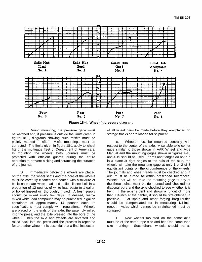
TM 55-203
Figure 18-4. Wheel-fit pressure diagram.
c. During mounting, the pressure gage mustbe watched and, if pressure is outside the limits given infigure 18-1, diagrams showing such misfits must beplainly marked "misfit." Misfit mountings must becorrected. The limits given in figure 18-1 apply to wheelfits of the multigage fleet of Department of Army cars.In mounting the wheels, both Journals must beprotected with efficient guards during the entireoperation to prevent nicking and scratching the surfacesof the journal.
d. Immediately before the wheels are placedon the axle, the wheel seats and the bore of the wheelsmust be carefully cleaned and coated with a mixture ofbasic carbonate white lead and boiled linseed oil in aproportion of 12 pounds of white lead paste to 1 gallonof boiled linseed oil, thoroughly mixed. A fresh supplyshould be mixed every few days. If desired, ready-mixed white lead compound may be purchased in galloncontainers of approximately 14 pounds each Itsspecifications must comply with regulations. Wheelsare placed on the ends of the axle, the assembly rolledinto the press, and the axle pressed into the bore of thewheel. Then the axle and wheels are reversed androlled back into the press and the process is repeatedfor ,the other wheel. It is essential that a final inspection
of all wheel pairs be made before they are placed onstorage tracks or are loaded for shipment.
e. Wheels must be mounted centrally withrespect to the center of the axle. A suitable axle centergage similar to those shown in AAR Wheel and AxleManual and the mounting gages shown in figures 4-18and 4-19 should be used. If rims and flanges do not runin a plane at right angles to the axis of the axle, thewheels will take the mounting gage at only 1 or 2 of 3equidistant points on the circumference of the wheels.The journals and wheel treads must be checked and, ifout, must be turned to within prescribed tolerances.Wheels that will not take the mounting gage at any ofthe three points must be demounted and checked fordiagonal bore and the axle checked to see whether it isbent. If the axle is bent and shows a runout of morethan 1/4-inch at the center, it should be straightened, ifpossible. Flat spots and other forging irregularitiesshould be compensated for in measuring 1/4-inchrunout. Axles which cannot be straightened must bescrapped.
f. New wheels mounted on the same axlemust be of the same tape size and bear the same tapesize marking. Secondhand wheels should be as
18-10

TM 55-203
nearly the same diameter as possible and must not varymore than half tape size when measured with a standardwheel tape. In selecting wheels for mating, inmachining wheels and axles, and In mounting them forinterchange service, the following points must beobserved:
(1) New wheels must not be mated withsecondhand wheels.
(2) One-wear wrought-steel wheels mustnot be mated with multiple-wear wrought-steel wheels.
(3) Double-plate cast iron wheels andwheels and single-plate nonbracketed-design cast ironwheels must not be mated.
(4) Cast iron wheels varying over 25pounds in marked weight must not be mounted on thesame axle.
(5) Cast iron single-plate nonbracketedwheels must not be mated with iron single-platebracketed wheels.
(6) Heat will not be applied to the hub ofa tight wheel with a torch to assist in disloading it.Wheels bearing any evidence of such heating or whichhave holes burned in the plate by a torch must bescrapped.
g. In handling pairs of mounted wheels, wheelsticks must not be used on the journal surface. Journalsof mounted axles must be coated with rust preventive,unless they are to be placed directly in the trucks.Before placing wheels with coated journals in a truck,the coating must be carefully removed with a suitablesolvent (para 18-33).
18-25. Boring-Mill Practice
a. Boring mills must be maintained with thetable running true and with the boring bar held true withrespect to the center and the plane of the table, andmust not chatter.
b. Chuck jaws must be properly alined radiallyand vertically. Contour of the chuck jaw may have ataper of 1 inch in 20 inches to correspond to the wheeltread line or it may be maintained vertically The boringbar must have a position micrometer adjustment for thecutters accurate to 0. 001 inch.
c. If roughing and finishing cutters are carriedon the boring bar at the same time, they must beseparated by a distance greater than the length of thehub, unless the roughing and finishing cuts are separateoperations With the wheel properly alined in position onthe mill with regard to concentricity and to plane, the
metal must be removed from the bore of new wheels by2 or more separate cuts; that is, 1 or more roughing cutsand 1 finishing cut. A radius or chamfer ofapproximately 1/8 of an inch must be turned at the entryor back end of the hub after the finishing cut Thefinished wheel bore must be within the limits forrotundity and taper and must be smooth and concentricwith the tread.
d. Inside and outside micrometer calipers arenecessary for the measurement of wheel bores andaxles wheel seats to insure consistent results. On eachwheel bore and axle wheel seat, a fine, smooth machinefinish is required and must be checked at not less thanthree points in its length, and on two different diameters,at each of these points, to insure rotundity and absenceof taper. The variation for any two of thesemeasurements must not exceed 0 002 inch. The boreshould be smaller than the wheel seat diameter, with atolerance of 0. 0. 01 inch per inch of diameter of wheelseat for wrought-steel wheels. For cast iron wheels, thetolerance should be equivalent to 0.005 inch per inch ofwheel seat diameter and a maximum of 0.102 inch.
e. Permissible variations in dimensions forcast steel wheels not shown by tolerances on individualdesign sheets are indicated below Figures 18-4 and 18-5show dimensions for machining 33-inch one-wear andmultiple-wear wheels
(1) Inside diameter-back face of rim. Theinside diameter of the rim at the back face of the wheelshall not vary more than 3/8 inch under the nominaldimension. The maximum diameter at this location isgoverned by the rim thickness and the tape size.
(2) Inside diameter-front face of rim. Fornarrow flange wheels, the inside diameter of the rim atthe front face of the wheel shall not exceed that at theback face of the wheel and shall not vary under thisdimension by more than 1/4 inch. For wide flangewheels, the inside diameter of the rim at the front faceof the wheel shall not differ from that at the back face ofthe wheel by more than 1/4 inch.
(3) Thickness of rim. In any wheel, theradial thickness of the rim shall not vary more than 1/8inch around the wheel.
(4) Corner at inside diameter of backface. A sharp corner is preferable to facilitatemeasurement. In any case, the radius of the cornershall not exceed 1/8 inch.
(5) Plane of back face. When wheels aregaged with a straightedge applied to back face of rim,no point on back face of narrow flange wheels morethan 1 1/4 inch from inside edge of rim shall be morethan 1/32 inch from the
18-11

TM 55-203
CA-33, Steel Freight Car Wheels
StandardCA-33 adopted 1956, revised 1960, 1962
Figure 18-4. Thirty-three-inch one-wear cast steel freight car wheel.
18-12

TM 55-203
CN-33, Steel Freight Car Wheels
StandardAdopted, 1962
Figure 18-5. Thirty-three-inch multiple-wear (MW) cast steel freight car wheel.
18-13

TM 55-203
straightedge. For wide flange wheels, no point on backface of rim shall be more than 1/16 inch fromstraightedge.
(6) Hub wall thickness. The thickness ofthe hubwall in any one wheel measured at any twopoints equidistant from the face of the hub shall not varyby more than 3/8 inch if the hub is not machined, nor bymore than 1/8 inch if the hub is machined. Hub lengthtolerance is based on finished dimension.
(7) Rotundity. Tread when gaged with aring gage must not have opening between tread andgage at any point over 1/32 inch.
(8) Diameter of bore. The diameter ofrough bore shall not vary more than 1/16 inch over, normore than 1/8 inch under the dimensions specified. Thespecified rough bore shall be at least 1/4 inch less indiameter than the finished bore, subject to 1/16-inchtolerance and/or 1/8 inch under the diameter specified.
(9) Eccentricity bore. Eccentricitybetween the rough bore and tread measured in theplane of the taping line shall not exceed 1/8 inch.
18-26. Machining Axles
a. The modern design of the center-drive axlelathe features antifriction bearings in the head- stock,tallstock, and driver chuck. This lathe is capable ofhigh-speed operation using carbide tools. An averageproduction of 10 to 12 axles in 8 hours is possible onthis type of machine.
b. Greater production can be secured fromend-drive axle lathes if available. One design usesseparate drive motors on the headstocks and tailstocks,two carriages with a swivel toolholder and, if desired, anopposed equalizing burnishing attachment on eachcarriage. Since axles are turned and burnished on onemachine and may be rolled into and out of the machine,machining time is greatly reduced This machineoperated by one man has a production rate as high as18 axles in 8 hours.
c. Machining diesel locomotive or streamlinedpassenger car axles from rough-turned blanks re- quiresmore care than machining freight car axles whichnormally do not require turning the body of the axlebetween the wheel seats. The severity of the servicerequired of these axles necessitates particular attentionto the surface condition of all highly stressed steel parts,and good shop practice is to grind the axles all overafter they have been machined.
d. The journals of freight car axles must berolled or burnished to a fine, smooth finish after
machining. Burnishing lathes have antifriction bearingsthroughout; an end-drive arrangement; and twocarriages, each holding two opposed rollers withequalizing screws. Rollers can be fed by handwheel orby hydraulic cylinders which permit greater pressures.The average output on a machine of this type is 48axles on an 8-hour shift.
18-27. Refinishing Journals on Wheel Pairs
a. Defective journals on wheel pairs areregularly turned on axle lathes similar to thosepreviously described except for modifications toaccommodate and swing the wheel pair. Center- drivejournal lathes (fig 18-6) are modified by providing deepgaps in the bed for the wheels and a hinged, splitcenter-drive arrangement which can be opened to admitthe axle. The carriages are equipped with either singleor opposed burnishing rolls. The average output of amachine of this type using carbide tools is 16 pairs in 8hours.
b. The end-drive axle lathe is furnished withboth headstock and tallstock raised to swing 49 inchesover the bed The two carriages are arranged for swiveltype toolholders, carbide tooling, and opposedburnishing rolls. Owing to the lathe's design, a simple,shop-built loading arrangement is possible. Productionwith 1 man operating the machine will be 20 to 25 wheelpairs in 8 hours.
18-28. Wheel Lathe ,Practice
a. General
(1) When a pair of standard one-wear,multiple-wear wrought-steel, or multiple-wear cast-steelwheels is removed from service because of a normalservice defeat, the wheels may be placed in a lathe andmachined to a new tread and flange contour with minorexpense and little loss of time. This process is thenrepeated as occasion demands until the rim is finallyreduced to the scrapping limit of 3/4-inch thickness forfreight cars and 1-inch thickness for passenger cars.
(2) A minimum number of 33-inchnominal diameter cast steel and wrought-steel wheelsand 36-inch nominal diameter wrought-steel wheels ofvarious hub diameters should be held in stock. Either33-inch or 36-inch nominal diameter wrought-steelwheels which have been condemned at 1-inch rimthickness for use under passenger cars may bereapplied under freight cars for an additional serviceperiod before they reach the final 3/4-inch rim thicknesscondemning
18-14

TM 55-203
Figure 18-6. Typical center-drive journal lathe.
limit. Wheel shop foremen, inspectors, and wheel-latheoperators should be thoroughly familiar with wrought-steel wheel defects.
(3) Normally, the turning of wheels isperformed to correct ordinary service defects, such asthin flanges, vertical flanges, high flanges, and slid-flatspots. The tread should be machined to a smoothfinish. If a wheel is turned and released for service aftertoo rough a cut, it will be worn away rapidly by the railand brakeshoe. Moreover, brakeshoes may grab,causing slid-flat spots, which in turn result In thermalchecking.
b. Lathe and Tools
(1) To get a good head surface, a sturdylathe with ample power is necessary. A lathe operator
should not have to force his machine in order to turn outthe requisite number of wheels. If he does, the finishedsurface will have chatter marks or the fish scaleappearance, which indicates poor workmanship.
(2) The tools necessary to complete theoperation of restoring the tread and flange contour are aroundnose roughing tool or round-button tool, which isused to cut the top off the flange and to rough off thetread to within about 3/32 of an Inch of the finished treadsurface, and three finishing tools The finishing tools areforming blades and act as scrapers rather than asordinary cutting tools. All the tools are held in a turrettype of sliding toolpost, so that it is not necessary tochange tools during the operation.
18-15

TM 55-203
18-29. Steel-Wheel Gage
a. Before a pair of wheels is put in the lathe,each wheel should be taped and gaged with a steel-wheel gage at the point where the flange and rim arethinnest. The gage should be applied to at least threepoints around the circumference and at least a quartercircle apart. The tape size, the rim thickness, and theamount to be turned off the tread to restore the contouras read from the gage should be chalked on thebackplate of each wheel. On some wrought-steelwheels, especially those that have been in service along time, the inside edge of the rim is not clearlydefined because the surface is rounded at the pointwhere the scale on the long leg of the wheel gageshould intersect the line of the inside surface of the rim.Where such a condition is encountered, a straightedgemay be applied to the inside surface of the rim to protectthe line of this surface over to the scale on the edge ofthe gage, and the gage reading may be obtained at thepoint where the straightedge intersects the scale.
b. The steel-wheel gage is so calibrated that,when applied as shown in figure 4-26 with the leg flatagainst the back of the rim and the end of the movablefinger pressed against the face of the flange, the scaleon the finger will show in sixteenths of an inch theamount of metal to be removed at the center of thetread in order to restore the flange contour to thewitness groove. The 0 mark on the finger correspondsto a normal flange thickness of 1 5/32 inches, 5/8 inchabove the baseline. The specification tolerance permitsthis dimension to vary 1/16 of an inch over but maynever be less.
c. The witness groove in the flange serves twopurposes. First, its presence in the finished turnedwheel shows that the lathe operator has not wastedservice metal by turning more off the tread thannecessary Second, if the wheel has a thin or verticalflange, the witness groove saves 1/8 inch of servicemetal each time a wheel is turned. However, thewitness groove must not be more than 3/64 of an Inchdeep (fig. 18-7) and must not extend into the throat ofthe flange. Owing to the important part the throat playsin wheel service and safety, it is essential that theselimits for the witness groove be observed.
18-30. Centering or Recentering Axles
Wheel shops should clean out the centers onsecondhand axles, using a grinder to remove any burrsor rolled-over edges. Heavy-duty stationary
Figure 18-7. Method of applying steel-wheel gage tocheck depth of witness groove in flange.
machines are used for this purpose. In general, theyinclude mechanically or hydraulically operated clampingblocks which grip either the wheel seat or the journal.The headstock and tailstock have individual motors,each driving a tapered reamer or cutter which iscentered with the clamping blocks The design is suchthat the axle can be rolled in and clamped by the blocks,and the reamers can be fed into the ends of the axleautomatically until they reach an adjustable stop.
18-31. Axle-Lathe Practice
a. Axle lathes must be maintained so that lathecenters are In alinement and the wear between the waysand the tool carriages must be taken up so machining ofaxles is truly concentric and without taper or chatter.Spindle bearings must be renewed when necessary toinsure accurate turning. Lathe centers must bereground or renewed when they show signs of wear.
b. The lathe tools used for finishing cuts oncollars, journals, and wheel seats should have an edgeapproximately 1 1/4 inches wide and be absolutelystraight except for a 1/8-inch radius at one side forcutting the back or dust-guard fillet, or some other toolarrangement must be used that will give equivalentresults. Separate tools must be used for the roughing
18-16

TM 55-203
and finishing cuts Sharp-nosed tools and coarsehorizontal feeds must not be used to finish wheel seatsurfaces.
c. Wheel seats must not be polished or filed.A smooth machine cut gives the best results. Outsidemicrometer calipers must be used for measuring axlewheel seats.
d. A taper of 1/32-inch diameter extending amaximum of 1/2-inch from the dust-guard seat must beturned in the wheel seat to insure entry into the wheeland to prevent tearing and gouging during mounting.Depressions, continuous streaks, or injuries to thesurface of the metal of the wheel seat or journals mustbe removed by a machine cut in a lathe.
e. Centering holes in the ends of axles musttaper at an angle of 60°. To insure concentricity whenturning, center holes must be wiped clean before theaxles are placed in the lathe. Any burrs formed aroundcenters by turning must be removed.
f. Files should not be used on journal surfacesor fillets, but they may be used to break the sharp edgesof the end collars and the dust guard seat Journals mustnever be ground with a coarse abrasive, but they maybe smoothed with No. 180 grit or finer abrasive clothunder light pressure.
g. Journals should be rolled to a finish with ahardened steel roller which preferably has a face 1 1/4inches wide and edges which are turned to a 1/8-inchradius for the collar end and a radius at the other end tosuit the journal fillet. The roller should be mounted witha hardened pin and bushing or by roller or ball bearingsin a shank to fit the toolpost.
h. While journals are being rolled, they mustbe coated with suitable oil Satisfactory mixtures are 1 or2 parts of lard oil and 1 part of lard oil to 3 parts of redmachine oil. Before journal surface is rolled, it must beclean and free from metal chips.
i. Journal fillets and end collars must bemachined smooth before they are rolled. Dust guardseats should be finished smooth and may be rolled. Theend collar must be smooth to avoid disturbing thepacking. The horizontal surfaces, when the journaldiameter has been reduced 1/4 inch or more, must beturned and rolled to maintain the same difference in
diameter between the journal and the collar as whennew.
j. Before use, all unmounted axles must bechecked in the lathe or between centers for rotundity,concentricity, and absence of taper of wheel seats andjournals. Where out of tolerance, correction must bemade.
k. Wheel seats of secondhand axles must bereturned before being remounted All second-hand axlesshould be magnetic-particle tested before they areremounted. If the journal surface or end of the axle hasany discoloration due to overheating (a light-straw ordark-straw color or any departure from the normal brightfinish of the journal) or if circumferential checks orcracks are found in the journals, wheel seats, or body ofthe axle, the axle must be scrapped unless thediscoloration, checks, or cracks can be turned outwithout going below the condemning limits.
18-32. Matching Wheels and Axles for Mounting
Current practice is the use of step sizes in turningwheel-fit diameters in the axle lathes. The steps are inincrements of 1/32 of an inch, with the minimumdiameter the shop limit for each particular size of axle.The step sizes can be numbered from 1 to 13. Size No.1 is the minimum or shop limit, No. 9 the standard, andNos. 10 to 13 oversizes. The wheels are bored to matchthe axles, and a lineup of the axles and size numbers islisted on a chart for the guidance of each boring-milloperator. This method of operation requires that onlyone nominal size of axle be handled each working day.
18-33. Protective Coating on Journals
The journals of all axles on wheel pairs must be coatedwith a rust preventive which will not wash away butwhich may be wiped off easily. The journals ofunmounted axles, if placed in storage, should likewisebe protected by a suitable coating. It is essential thatthe coating be applied as soon as possible after thejournal has been burnished, since rusting may startwithin an hour or so. There are various rust preventiveson the market which are suitable for this purpose, or amixture of paint and oil may be used. The normalmethod of application is with a brush. The entiresurface from the wheel hub to the end of the axle mustbe covered.
18-17

TM 55-203
Section V. PAINT SHOP, RAILWAY CARS
18-34. General
Although freight cars may be painted in the open, it isgenerally considered advisable to paint them in a shopPassenger cars should be painted in a shop or closedbuilding. Cars can be painted more quickly In a shop,and weather conditions do not interfere; moreover, theresults are better. Freight cars normally are preparedfor painting outside the paint shop, and protection fromthe weather is not always necessary. The size of a paintshop for freight cars may be determined by the numberof cars in service, their general condition, and thenumber of cars to be painted annually, the length oftime in the shop depending upon the amount of cleaningdone inside the shop, the number of coats of paintapplied, and the stenciling. Painting is discussed inchapters 13 and 14.
18-35. Car Paint Shop Facilities
a. The paint shop should be constructedentirely of fireproof material and have a concrete floorwith a smooth surface and good drainage. The floorshould be waterproof, and its corners should be roundedto facilitate cleaning. All shelves and lockers should beof noncombustible material. Any source of sparking,such as electric wiring, switches, or belt-drivenequipment, which would produce electric arcing or staticelectricity, should be eliminated or installed in such away that paint fumes cannot Ignite. A paint shop shouldbe provided with an automatic sprinkle system and fireextinguishers in accordance with fire prevention lawsand recommendations.
Where possible, the paint should be stored in a separatebuilding (para 13-2d(7)).
b. The same type of sandblasting shed may beused for both freight and passenger cars. It should bemade long enough to take two cars at a time when thenumber of cars to be handled so requires, and ifpossible, should be served by the transfer table. Suchlocation will avoid the annoyance of the dust in the othershops and will save delays incident to switchingmovements (para 13-2e).
18-36. Scaffolding
a. Scaffolds may be of the elevator type andmay extend the length of the enclosure. There shouldbe one on each side of the car to be painted. Theplatform may be raised and lowered by two cablecontrols which extend from end to end. The platform israised when one cable is pulled and lowered when theother is pulled. Safety devices limit the maximum andminimum height to which the platform will go.
b. Platforms should be made of expandedmetal which presents a nonskid surface and enables theworkmen to see through the platform. Thus, work canproceed on at least two different levels of any side ofthe car at the same time, be- cause the platform for theupper level workmen can be raised so it does notinterfere with the men standing on the floor and workingon the lower part of the car.
18-18
TM 55-203
CHAPTER 19
SHOPS, LIGHT (RUNNING) REPAIRS
Section I. CAR REPAIR PLATOON, TRANSPORTATION RAILWAY
EQUIPMENT MAINTENANCE COMPANY, TRANSPORTATION
RAILWAY BATTALION, TOE 55-228
19-1. Mission and Capabilities
The mission of the car platoon is to inspect, condition,and make running repairs (light repairs) on railway cars.This unit is adequate to inspect, condition, and makerunning repairs to approximately 800 railway cars perday and to perform running inspections forapproximately 2,0.00 rail- way cars per day. Normally,the TOE for the car platoon, transportation railwayequipment maintenance company, transportationrailway battalion, will include only equipment necessaryto per- form the above functions. In theaters ofoperations, the TOE equipment may be greatlyaugmented by facilities and equipment contained inexisting shops, particularly where damage to car shopsis small.
19-2. Planning Factors
a. General. The shortage of all types of carsin a theater of operations makes it essential that repairtracks be designed and equipped to complete suchrepairs in the shortest possible time. This is even moreImportant on a repair track where an appreciablepercentage of the cars handled are loaded. Delay inInspection, classification, switching, repairs, and return
of the car to service means delay in the receipt of theshipment by the consignee.
b. Track Facilities. There are a number offactors which should receive serious consideration whenplanning new, or remodeling old, light freight car repairfacilities to provide the most efficient operation
(1) The operation of the light repair shopis particularly important. It should be adjacent to aclassification yard or terminal yard so that bad ordercars can be placed in the repair yard without delay.Practically all classification yards have a sizable repairtrack so located that a switch engine can readily placeand remove cars.
(2) The repair yard should be providedwith through tracks and a switching lead at both ends.With such an arrangement, switching moves arereduced to a minimum. The size of the repair tracklayout will depend entirely on the number of cars to berepaired in 24 hours, the extent of such repairs, thetypes of cars, the frequency of switching, and the size ofthe repair force. A careful study should be made of themaximum number of cars to be repaired at one time todetermine track standing space required.
Section II. LIGHT FREIGHT CAR (RUNNING) REPAIRS
19-3. General
a. This section discusses the ideal standardsfor light repairs and facilities. The situation in theoversea area concerned will dictate the degree to whichthese standards can be adopted.
b. Light freight car repairs can be consideredas comprising repair, renewal, or overhaul work whichcan be completed in 1 to 3 days (usually not exceeding40 hours). Such work includes one or more of thefollowing operations:
(1) Replacing journal boxes.
(2) Replacement, repair, or cleaning ofairbrake equipment.
(3) Renewing brakeshoes, levers, rods, orpins.
(4) Changing worn or defective wheels,truck side frames, bolsters, or draft gear.
(5) Renewing or repairing ladders, steelrunning boards, platforms, door hinges, latches,etc.
19-1

TM 55-203
(6) Patching, renewing, or repairingcorroded or broken plates, angles, side stakes, centersills, and steel underframe parts.
(7) Patching or replacing wooden floors,lining, running boards, etc.
(8) Repairing sides, ends, or roofs.
(9) Installing, adjusting, or repairingspecial loading devices.
(10) Repairing cars for upgrading toreceive a higher commodity classification.
(11) Restenciling required.
c. The preparation of cars for highercommodity loading is an important function of any lightrepair yard. Cards for commodities such as flour, grain,sugar, perishable rations or supplies, and similarmaterials subject to damage must have good floors,sides, and roofs to prevent rain, ice, snow, or cindersfrom entering. Boxcars for this type of loading shouldbe reworked on the repair track to insure theircontinuance in such service.
19-4. Light Repair Track
a. The physical size of the repair track facilitieswill depend upon the volume of the work to beperformed. A small repair shop located at the end of abranch line or at a small yard where 10 or more men arestationed (exclusive of train-yard inspectors or oilers)should have buildings for an office; latrine facilities; anda storeroom to house all material except wheels,bolsters, truck sides, couplers, and draft gears. Theoperation may be so small that a shed, roof, or buildingover the repair track is not justified, except in areaswhere extremes In weather are encountered.
b. A hard-surface pavement should beprovided at the side of or between the working tracks toform a roadway and to permit jacks, wheels, couplers,draft gear, etc., to be hauled from storehouse or storageplatforms to a car undergoing repairs The platformshould be extended to provide a connection withstorehouse, shop buildings, and an access road. Theaccess road will permit material and supply trucks,ambulances, and firefighting equipment to reach therepair shop facility.
c. A minimum facility should also include acrane truck, a pillar crane, or a jib type crane with apower hoist for loading and unloading wheels. A cranetruck is desirable, since it can be used for handling all
types of heavy material In addition to loading,unloading, and handling wheels.
d. An air compressor with necessary pipingand outlets at all convenient locations is essential. Anelectrical distribution system should be provided withoutlets for an electric welding set, electric tools, andfloodlighting if necessary for night shift work.
19-5. Large Repair Tracks
a. The layout of a large repair track where 50or more car repairmen are stationed is dependentprimarily upon the plan of operation Either the carsrequiring repairs are placed at one repair position in theyard, and men, tools, and materials are moved to eachcar, or, if the spot system is used, the cars to berepaired are moved from one point to another forprogressive repairs, and cars which require wheelchanges are segregated. Cars for wheel change-out orother repairs are placed on one or more tracks andmoved successively to a location provided withpermanent jacking pads or blocks, pneumatic jacks, anda fixed or portable frame or hoists for dismantling andassembling truck sides, bolsters, etc. The wheelinglocation must be adjacent to wheel storage tracksequipped with a crane, dolly car, or turntables for easymovement of wheels to and from the working area.
b. The spot system for miscellaneous lightrepair work can be used effectively in those repair yardswhere the cars to be repaired are predominantly of oneclass or type. This would be true In a yard in a coal areawhere hopper cars are handled, at a tank car terminalnear a refinery or oil-producing section, or at, a terminalor yard for refrigerator cars, etc. The spot system hasmany advantages where the type and volume of workpermit At repair positions, material, tools, and suppliescan be stored in bins, racks, or cupboards adjacent tothe location where they are to be used. This savesdelays and manhours and reduces the time required tomove from one car to another.
c. It is difficult to have a repair track operatingon the spot system if all types of loaded or empty carsmust be handled and if repairs vary from lightoperations such as the renewal of running boards,repairs to safety appliances, etc., to straightening orrenewing bent sheets, ends, or doors, or other heavywork on open-top or enclosed cars. It is possible,however, to use the spot system for wheeling cars, eventhough its use on the repair track is not justified. Thecooperation of the train operating company is essentialto the success of such an arrangement, since carsrequiring wheel change must be
19-2

TM 55-203
segregated from other bad-order cars, and thisnecessitates extra switching A careful study is requiredof all factors to determine which system to use.
19-6. Shop Buildings
a. It is desirable, particularly at a small carrepair facility, to house all shops, offices, etc, in onebuilding, for convenience. Provision of plumbing,heating, light, and other services is simplified.
b. Offices should be provided for the foremanand clerks with a small locker room, toilet facilities, andfile storage for office personnel
c. Washrooms and locker rooms shouldprovide latrines, washbasins, and shower stalls.Individual lockers for car repair platoon personnel arerequired for storage of uniforms, individual weapons,and other items of military equipment not needed on theJob.
d. Building space is necessary for heatingboilers, air compressors, and fire pumps, if theseservices are not available from a nearby shop.
e. Toolroom space is essential for storage andprotection of jacks, portable tools, air hose,oxyacetylene torches, electric welders, cable, and handtools.
f. Because of fire hazards, the building forstorage of waste, prepared packing, and oil should be offireproof construction and be separated from otherbuildings It should be large enough for packing vats ortanks, as well as for storage of a carload of waste.
g. The airbrake room or building furnishesspace for the storage of reconditioned airbrakecomponents If the volume of work justifies, this roomshould be equipped with necessary test racks andplates.
h. Pipe and sheet metal repairs normally willnot require a great amount of space, and the necessarymachines can be installed at one of the fabricating shopor planing mill. The blacksmith shop, particularly at asmall shop, may also be combined with other shopfacilities It is preferable, however, to have it in aseparate, well ventilated room or building, because ofthe fumes, dust, and dirt resulting from its operation.
i. A room or building is essential to housemachinery for fabricating operations on steel and fordrilling, threading, and grinding This space should beconvenient to storage platforms, driveways, and workingareas and should provide ample room for handling largeplates.
j. The wood mill and planing mill presentcertain fire hazards and should be in a separate buildingor have a firewall separating them for adjacent shops orfacilities. Lumber must be reworked for use as flooring,siding, or sheathing in camp cars and cabooses. It isalso desirable to provide a shed near the wood mill forthe storage of lumber An open-side shed should havean overhanging roof to protect the lumber from drivingrains.
k. The paint shop can be a small room orbuilding, since the average light repair track will notattempt any extensive painting operations. It should beprotected from fire hazards. Space should be availablefor the storage of paint, stencils, and supplies.
l. In addition to the service buildings, seriousconsideration should be given to the desirability ofproviding a shed or an enclosed building over the repairtrack area. Elimination of lost time and delays due tobad weather may justify the construction.
m. The amount of machinery and equipment tobe provided will depend upon the volume and type ofwork to be performed The small repair yard, and inmany cases even the larger yard, can be supplied withprefabricated parts, precut lumber, and reconditionedairbrake, truck, and draw gear assemblies from a centrallocation
n. TOE equipment is considered sufficient toperform 1- to 3-day repairs, usually not exceeding 40hours.
o. The storehouse room or building shouldhave adequate space for storage of bolts, nuts, smallmaterials, and supplies in bins, racks, or cupboards.Heavy items of car material can be stored on outsideracks or platforms, since this type of material is notaffected by the weather.
p. Wheel storage tracks preferably should bearranged at right angles to the repair tracks. Sufficientdouble storage tracks should be provided to permitclassification of wheels by journal sizes, steel or castiron, new or reworked.
19-7. Materials Handling Equipment
a. The importance of providing adequatematerials handling equipment cannot be overemphasized. Its use in loading, unloading, and movingmaterials and supplies will expedite car repair work,reduce delays, and effect considerable economies inoperation.
b. The well-equipped car repair yard should beprovided with a truck crane of 8,000- to
19-3

TM 55-203
10,000-pound capacity. Among other things, this unitcan be used to load and unload wheels and heavymaterials, carry mounted wheel sets to and from thestorage tracks, handle doors in repair operations,straighten car ends, and shift loads It is much moreversatile than the locomotive type of on-track crane.
c. A forklift truck can be used to handlematerial on skids, mounted wheels, and other similaritems and to assist in actual repair operations. Similarly,a tractor with trailers is a valuable piece of equipment.The tractor, If of adequate capacity, may be usedoccasionally for shifting cars.
d. Small platform trucks are desirable forhauling light materials and supplies from the storehouseto the point of use. Oxyacetylene tanks, electricwelders, or supply cabinets can be mounted on platformtrucks for mobility.
e. Hand wagons, trucks, or buggies arevaluable for moving tools, supplies, or materials. If thisequipment is to be hand propelled, it should be as lightas possible and be equipped with ball or roller bearingson axles.
Section III. LIGHT PASSENGER CAR (RUNNING) REPAIRS
19-8. General
Light passenger car maintenance is interpreted to meanrunning repairs and cleaning and servicing operations atcoach yards and terminals before cars are again readyfor service. The work involved includes everything fromrepairing a door latch to changing out slid-flat wheels Itincludes replacing a defective light, fixing inoperative airconditioning equipment, inspecting running gear andsafety appliances, testing airbrakes, cleaning andtouching up car exteriors and interiors, checkingbatteries, and putting all required supplies aboard.
19-9. Coach Yard Layout
Coach yard tracks should be spaced so as to assuresufficient width on the runways to permit material andtrucks to pass each other. It will also permit truckingaround men who are working under the cars oroccupying part of the runway with their material andapparatus without interference with their work. Steam,air, water, and electric outlets can be located along thecenter of the runway from either overhead orunderground lines extending to the boiler plant. Thepowerplant will of necessity include one or more aircompressors, electrically or diesel engine driven
19-10. Wheel and Truck Repairs
a. Car wheels are subject to many defects,discussed in chapter 4, the repair of which necessitatesthe removal of the axle with its pair of wheels. Removalof complete trucks because of defects is infrequent, ascompared with the removal of mounted wheels. Mostcoach yards are equipped with facilities to remove andreplace pairs of wheels and complete trucks, the kind orextent of facilities varying with the amount andcharacter of the work in each yard. In large terminals,pairs of wheels are changed on pneumatic orhydraulically operated wheel-dropping jacks usually
equipped with V-blocks to engage the axles Trucks arereleased by means of hand or power-operated jacks thatlift the car sufficiently to permit the trucks to be rolledfrom it.
b. Drop-pit tables simplify the operation, as therails spanning the pit are a part of the movable tableWheels supported on these rails can be removedwithout any part of the lifting mechanism coming incontact with the axle. This type of equipment shouldhave the following characteristics:
(1) A capacity sufficient to raise a pair ofwheels above the rails spanning the pit.
(2) Detachable tabletops to engage thewheel treads instead of the axles, so as to avoid havingto strip the axles of pulleys or other attachments.
(3) Electrical operation to provide a lowcost source of power and to permit the use of remotecontrol.
19-11. Inspection Facilities
a. In most cases, complete inspection can beaccomplished best at inspection pits. With theexception of a pit track of required capacity forinspection, the general requirements in terminal facilitiesfor passenger cars usually are included in the servicingfacilities of a coach yard. Consideration should be givento the location of the 'inspection pit track at a coach yardto permit maneuvering the train into the faculties withoutdelays and to reduce switching operations to aminimum.
b. The car unit capacity or length of theinspection pit, and the necessity for componentsservicing facilities at the pit track, such as usually aremaintained in passenger car servicing
19-4

TM 55-203
yards, depend upon the requirements and the tacticalsituation in the theater of operations. The number oftrains requiring terminal inspection, repairs, and
servicing; the length of trains; and the schedules orlayover time are factors to be considered.
19-5
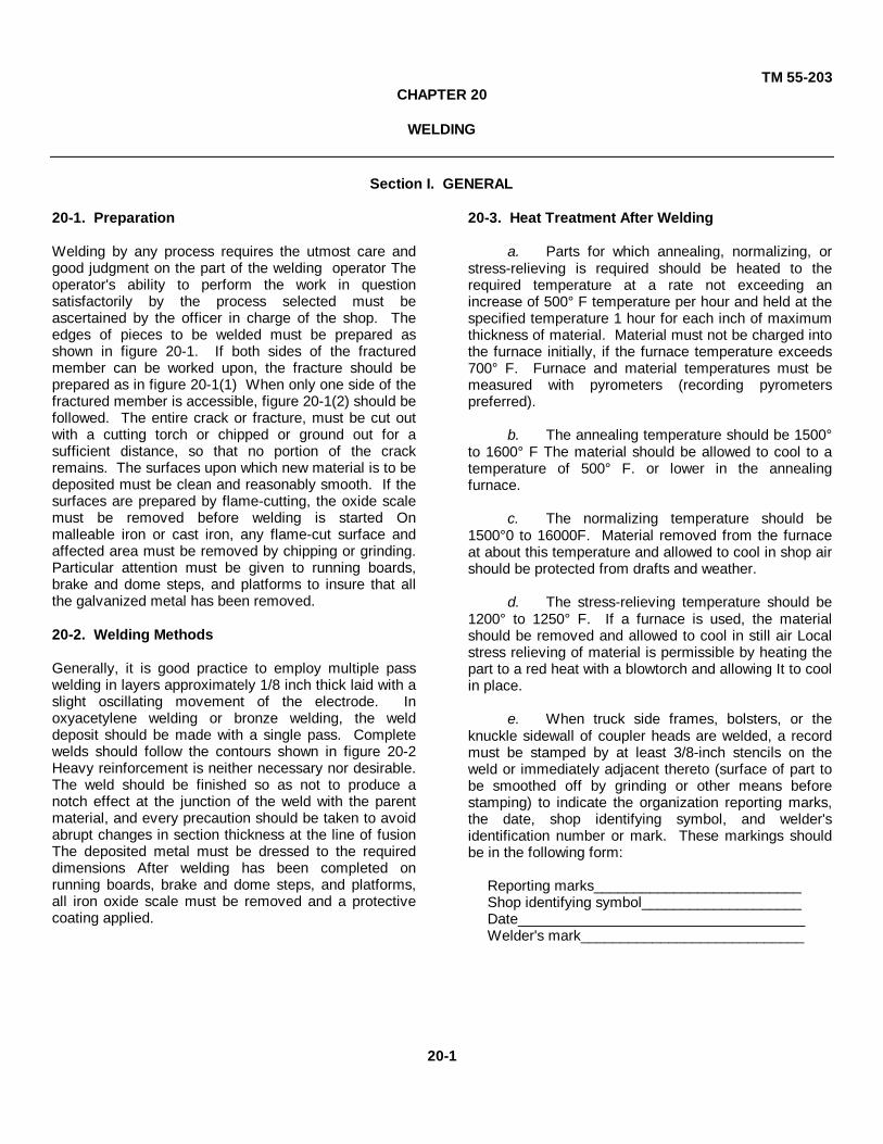
TM 55-203CHAPTER 20
WELDING
Section I. GENERAL
20-1. Preparation
Welding by any process requires the utmost care andgood judgment on the part of the welding operator Theoperator's ability to perform the work in questionsatisfactorily by the process selected must beascertained by the officer in charge of the shop. Theedges of pieces to be welded must be prepared asshown in figure 20-1. If both sides of the fracturedmember can be worked upon, the fracture should beprepared as in figure 20-1(1) When only one side of thefractured member is accessible, figure 20-1(2) should befollowed. The entire crack or fracture, must be cut outwith a cutting torch or chipped or ground out for asufficient distance, so that no portion of the crackremains. The surfaces upon which new material is to bedeposited must be clean and reasonably smooth. If thesurfaces are prepared by flame-cutting, the oxide scalemust be removed before welding is started Onmalleable iron or cast iron, any flame-cut surface andaffected area must be removed by chipping or grinding.Particular attention must be given to running boards,brake and dome steps, and platforms to insure that allthe galvanized metal has been removed.
20-2. Welding Methods
Generally, it is good practice to employ multiple passwelding in layers approximately 1/8 inch thick laid with aslight oscillating movement of the electrode. Inoxyacetylene welding or bronze welding, the welddeposit should be made with a single pass. Completewelds should follow the contours shown in figure 20-2Heavy reinforcement is neither necessary nor desirable.The weld should be finished so as not to produce anotch effect at the junction of the weld with the parentmaterial, and every precaution should be taken to avoidabrupt changes in section thickness at the line of fusionThe deposited metal must be dressed to the requireddimensions After welding has been completed onrunning boards, brake and dome steps, and platforms,all iron oxide scale must be removed and a protectivecoating applied.
20-3. Heat Treatment After Welding
a. Parts for which annealing, normalizing, orstress-relieving is required should be heated to therequired temperature at a rate not exceeding anincrease of 500° F temperature per hour and held at thespecified temperature 1 hour for each inch of maximumthickness of material. Material must not be charged intothe furnace initially, if the furnace temperature exceeds700° F. Furnace and material temperatures must bemeasured with pyrometers (recording pyrometerspreferred).
b. The annealing temperature should be 1500°to 1600° F The material should be allowed to cool to atemperature of 500° F. or lower in the annealingfurnace.
c. The normalizing temperature should be1500°0 to 16000F. Material removed from the furnaceat about this temperature and allowed to cool in shop airshould be protected from drafts and weather.
d. The stress-relieving temperature should be1200° to 1250° F. If a furnace is used, the materialshould be removed and allowed to cool in still air Localstress relieving of material is permissible by heating thepart to a red heat with a blowtorch and allowing It to coolin place.
e. When truck side frames, bolsters, or theknuckle sidewall of coupler heads are welded, a recordmust be stamped by at least 3/8-inch stencils on theweld or immediately adjacent thereto (surface of part tobe smoothed off by grinding or other means beforestamping) to indicate the organization reporting marks,the date, shop identifying symbol, and welder'sidentification number or mark. These markings shouldbe in the following form:
Reporting marks__________________________Shop identifying symbol____________________Date____________________________________Welder's mark____________________________
20-1

TM 55-203
Figure 20-2. Weld contours.
Section 11. WELDING LIMITATIONS
20-4. General
Unless otherwise provided, welding by either the electricor oxyacetylene process will be permitted on parts withinthe limitations referred to, except that parts made ofhigh alloy steel subject to severe brittleness must not bewelded nor have fusion heats applied to them. Heat-treated carbon steels must not be welded nor havefusion heats applied to them unless such parts can beheat treated again (duplicating the original heattreatment) after welding to restore former properties.
Car parts other than those listed in paragraphs 20-5 to20-8 may be repaired by welding, provided the weldedmetal joint equals or exceeds the physical properties ofthe section welded. Where it is permissible to weldmalleable iron parts, it is mandatory to use theoxyacetylene (or equivalent gas) bronze weldingprocess for making repairs in sections subject to tensilestresses. For malleable iron sections subject tocompression stresses only, it will be permissible to usethe arc-welding process. Care must be exercised to
20-2
Figure 20-1. Preparation of edges.

TM 55-203
see that the general condition of the part to be repairedis not due to defective material or weak design,conditions which are often evidenced by the existenceof previously made welds. Such parts should not berepaired.20-5. Limitations on ReclamationSpecific limitations on reclamation by either electric oroxyacetylene welding are as follows:
a. Axles, Solid. No welding permitted.b. Bolsters, Cast Steel, Grade B. Welding
cracks or fractures from the end to within 12 inches ofthe center plate (as shown in AAR Interchange Manual)is permissible, providing crack or fracture does notextend more than forty percent through the cross-sectional area of the casting. Welding cracks outside ofthis area is prohibited. Bolster must be removed fromcar before welding and normalized after welding.
c. Bolsters, Cast Steel, Grade C and HighTensile Steel. Welding limitations as discussed above,except that castings shall be uniformly preheated to atemperature of between 300° F and 6000 F and thewelding shall be accomplished while the casting ismaintained at a temperature of above 3000 F.
d. Bolsters, Pressed- or Structural-Steel. Norestrictions.
e. Braces, Body. No restrictionsf. Brake Beam Tension Members. No welding
of cracks or fractures or building up permitted.g. Brake Steps Metal. No welding permitted
except for restoring original construction weld.h. Carlines. No restrictions.i. Center Plates, Malleable Iron. Must be
removed and be bronze welded.j. Center Plates, Cast or Forged Steel. No
restrictions. If removed from car, it is recommendedpart be stress-relieved after welding.
k. Check Plates, Follow. No weldingpermitted when section is broken out between key slots.
l. Couplers, Rigid Shank Lengths. May berestored by welding.
m. Couplers, Swivel Shank, Lengths. May berestored by welding. Must be normalized after welding.
n. Couplers, Key Slot. May be restored bywelding. Must be normalized after welding.
o. Coupler Draft Keys. No welding permitted.p. Coupler Knuckles, High Tensile. Worn
surfaces may be built up by welding.q. Coupler Knuckles, Grade B. No welding
permitted.r. Coupler Pins. No welding permitted.s. Coupler Yokes, Horizontal, Forged Steel.
No welding permitted.
t. Dome Steps and Dome Platforms. Nowelding permitted, except for restoring original weld.
u. Draft Lugs, Cast- or Forged-Steel. Norestrictions.
v. Equalizers, Truck. No welding of cracks orfractures permitted
w. Grabirons. No welding permitted.x. Hanger, Brake Beam. Cracks and fractures
must not be welded. Building up worn eyes ispermissible.
y. Hanger, Spring or Bolster. Crack orfractures must not be welded. Worn areas may be builtup provided material remaining in part is not less than80 percent of the original section. Must be normalizedafter welding.
z. Hanger Bracket, Brake Beam. Cracks orfractures may be welded. Normalizing is required, ifweld is located closer than 1 inch from inside flange ofside frame. Brake hanger brackets may be renewed orother types substituted by welding. Normalizing isrequired, if weld is located closer than 1 inch from insideflange of side frame. Building up worn holes ispermissible.
aa. Heads, Brake Beams, Cast Steel. Norestrictions.
ab. Journal Boxes (Not Integral), Cast Steel. Norestrictions.
ac. Journal Boxes (Not Integral), Malleable orCast Iron. No welding permitted.
ad. Ladders and Supports. No weldingpermitted.
ae. Levers, Brake. Cracks or fractures must notbe welded Holes may be built up provided materialremaining in part is not less than 80 percent of theoriginal section.
af. Plates, End or Side. No restrictions.ag. Posts, End, Side, or Door. No restrictions.ah. Reservoirs, Auxiliary and Emergency
Airbrake, Cast Iron. No welding of body portionpermitted. Worn holes in lugs may be built up, and lugsfractured or broken off beyond 1/2 inch from body maybe reclaimed by bronze welding.
ai. Running Boards, Metal (Steel) (Except TankCars). Running board sections must be removed fromcar for welding repairs.
(1) Longitudinal running board betweenthe end running board saddles-welding of cracks andfractures permitted up to 50 percent of sectional area ofcomplete section.
(2) Longitudinal running boards extendingbeyond the ends of car-no welding permitted except torestore original construction weld.
20-3

TM 55-203
(3) Latitudinal running boards-welding ofcracks and fractures permitted up to 50 percent ofsectional area of complete section.
aj. Running Boards, Aluminum. No welding ofcracks or fractures permitted.
ak. Running Boards, Steel (Tank Cars Only).Only welding of cracks or fractures in running boardsections permitted, except to restore originalconstruction weld or if over running board support.Welding in connection with splicing of running boardsections over body bolsters, center sills, and crosssupports for purpose of renewing sections at theselocations permitted.
al. Sheets, Body or Roof. No restrictions.
am. Sill Steps and Their Supports. No weldingpermitted.
an. Shaft, Brake. No welding permitted.
ao. Stakes. No restrictions.
ap. Spring, Planks. No restrictions except that,where thickness is reduced to less than 1/4 inch owingto corrosion, spring planks must not be welded. Springplank must be removed for welding.
aq. Tanks of Tank Cars. Welding of any kind isnot permitted on tanks of tank cars unless the shopperforming such welding is certified by the AAR. Forwelding repairs to tanks of riveted or weldedconstruction, all applicable requirements of currentlyeffective DOT Regulations for Transportation ofExplosives and other Dangerous Articles, and AppendixR, AAR Specifications for Tank Cars must be fullycomplied with before cars are restored to service.
ar. Top Chord Angles of Open-Top Cars. Norestrictions.
as. Transom Truck (the Crossmember of EachSide of Bolsters Which Tires the Side Frames Together).May be welded in place by removing truck fromunderneath the car body.
at. Truck Sides, Cast Steel. Building up wornsurfaces and welding cracks within certain areas orwelding performed on other parts extending from framemembers, such as tie strap lugs on Andrews type sideframes, where the weld is over 1 inch from the framemember, is permissible on side frames of U-sectiondesign manufactured (as indicated by foundry marks) in1926 or before. The material remaining in the part to bebuilt up must be equal to 60 percent of the originalsection, or the area of the crack must be less than 40percent of the total area through the section at the pointof fracture. Welding or other cracks or fractures isprohibited. Brake hanger bracket repairs or renewalsmay be performed, however, as outlined in z above.
au. Truck Sides, Pressed- or Structural-Steel.No welding permitted.
av. Uncoupling Levers. No welding of cracks orfractures permitted.
aw. Wedges, Journal Bearing. AAR standarddrop-forged or cast-steel wedges removed from servicebecause they have reached the limit of wear may bereclaimed by reforging or fusion welding and restored tonew dimensions. Wedges thus reclaimed will beclassified as new. Journal bearing wedges may also bereclaimed by machining or grinding provided-
(1) Original top contour of wedge isformed to 50-inch radius.
(2) Nominal thickness of crown is notreduced more than 3/32 inch.
(3) Lengths over contract surfaces arerestored to nominal dimensions if reduced more than1/16 inch. Wedges thus reclaimed will be classified assecondhand.
ax. Wheels, Brake. No welding of cracks orfractures permitted.
ay. Wheels, Car, or Tires. No weldingpermitted.
20-6. Welding Regulations for Couplers and CastSteel Yokes
Welding is permitted for couplers and cast steel yokesunder the following regulations:
a. Welding practices permitted under theseregulations are confined to couplers and yokes made ofgrade B carbon steel. The work must be done onlyunder expert supervision and only at reclamation plantswhere facilities such as heat treating furnaces usingpyrometers (preferably recording pyrometers) and otheressential safeguards are provided, so that quality anduniformity of results may be assured. All existing rulesand restrictions with respect to welding of couplers andyokes remain in full force except as herein modified.
b. Cracks In couplers and cast steel yokes arewelded by the electric process, using a shielded arcelectrode.
c. Cracks in couplers must be prepared forwelding by single veeing as shown in figure 20-1(2), sothat the welding can all be done from the outside.
d. Cracks in yokes, if both sides of thefractured member can be worked upon, should beprepared as shown in figure 20-1(1) and the weldingdone from both sides. If only one side can be workedupon, preparation should be as shown in figure 20-1(2).
20-4

TM 55-203
e. In all cases, the entire crack should be cutout far enough back so that no portion of the crackremains in the metal, and the surfaces where new metalis to be deposited are clean and reasonably smooth.
f. If a gas pocket encountered when cuttingout a crack or making a weld cannot be entirelyremoved, the part must not be reclaimed.
g. On couplers, welds must be dressed off, sothat there is no projection on the front face, inside theguard arm, or at the bottom of the shank. Also, noprojections or beads which might interfere with operationof the coupler will be allowed inside the knuckle or lockcavities.
h. On yokes, welds must be dressed off flushwith parent metal on the inside and outside of ,strapsand in the key slots. Front end of key slots must begaged from rear bearing surface of yoke to insure equallengths on each side of the yoke so that it will line upproperly in assembly. After welding, couplers and caststeel yokes must be normalized. No welding ispermitted on forged steel coupler yokes.
20-7. Welding Coupler Cracks
a. Transverse cracks, including shrinkagecracks in the shank of the coupler from the rear end ofthe shank to and including the backwall of the horn, maybe welded There is no limitation in length or depth ofcracks that may be welded.
b. Cracks in the guard arm and the front faceof the coupler, including cracks extending the full lengthof the face into the lock opening and into top and bottomparts of the wall, may be welded. If a crack is more than1/16 inch wide, parts should be pressed back to originalcontour before welding is done.
c. A coupler having a 5- by 7-inch shank with a6 1/2-inch butt may be converted to one with a 9 1/8-inch butt by welding metal shims on the top and bottomof the butts in accordance with the following regulations:
(1) Shims must be cut to proper size 15/16 by 5 by 5 1/2 inches.
(2) Shims will be drilled In pairs to matchholes in related coupler butts.
(3) Coupler butts will be ground to giveneat seating of shims.
(4) Shims will be beveled 3/8 of an inchto 60° angle (or J-weld preparations given) for all aroundcontact face. No beveling of the coupler butt ispermitted.
(5) Shims will be tightened to weldingposition on the coupler butt by dummy pin and key, andcare will be exercised to see that shim edges are flushwith corresponding edges of the coupler butt.
(6) After shims are in position, they willbe welded to the coupler butt by the shielded arc electricmethod.
(7) All sharp corners of applied shimsmust be removed by grinding.
20-8. Cast Steel Yokes
a. Cracks in straps not closer than 3 inches tojunction with the rear of the yoke may be weldedregardless of extent or direction of the crack. If a crackstands open, a means must be used to hold the severedends alined in proper relation while welding, so that thelength of the crack is not changed.
b. Cracks anywhere in the front section of theyoke, including the key slot, may be welded.
c. Cracks in the rear end of yokes, including 3inches of adjacent strap, must not be welded.
20-5

TM 55-203
CHAPTER 21
SAFETY
21-1. Accident Prevention Program
a. A sound, practical accident preventionprogram is essential in decreasing accidents in the carrepair yard. Some of the elements that contribute to thesuccess of such a program are--
(1) Establishment of a shop safetycommittee, the membership of which should be chosen,in large part, from the rank and file and given authorityto enforce safety regulations.
(2) Establishment of sound safety rulesand
instruction In their observance.
(3) Enforcement of the rules
(4) Instruction in safer ways of doingeach job.
(5) Instruction in first aid.
(6) Fixing of responsibilities from top tobottom.
b. The following cautions are suggested infixing responsibilities:
(1) The usual causes of accidents shouldbe known.
(2) Snap judgments must be avoided. Aninvestigation should be conducted in each case todetermine the causes for the accident.
(3) Determination should be made of thereason why the safe method was not followed.
(4) Investigation should reveal whetherany unsafe condition was involved and why it existed.
(5) Action should be taken to prevent arecurrence.
21-2. Safety Rules
a. Safety rules are for the protection ofpersonnel, as well as for the safeguarding ofGovernment property. All personnel engaged in themaintenance of railway cars must be conversant withand obey the safety rules and special instructions.Situations not covered by the rules demand soundjudgment in applying correct principles of safety.
b. It must be realized that the rules contained
herein cannot be considered as all inclusive, since timeand conditions will dictate additions and deletions Theydo, however, cover the major safety hazards involved inthe maintenance of railway cars Detailed railway safetyrules are contained in DA Pam 55-1, a copy of whichshould be in each shop worker's possession.
21-3. General Rules
a. Persons in charge of work are responsiblefor the safety of the men under their supervision,including those temporarily borrowed or transferred fromanother division This does not preclude individualresponsibility. Personnel are responsible for their ownsafety and will not depend upon others to apply thesafety rules for them.
b. Inexperienced personnel must be properlyinstructed in safe methods of performing their work.
c. Personnel will familiarize themselves withtools, appliances, and equipment before use, makingcertain that their condition is safe.
d. Personnel will not cross, sit, or lie undercars, except in performance of duty, and then only whenprotection is afforded
e. Personnel will look in both directions beforecrossing, walking parallel to, or standing close to tracks.They must walk clear of tracks when duties permit andagainst the current of traffic A lookout must be kept inboth directions for approaching trains or cars.
f. Personnel will not step or walk on rails,frogs, switches, or interlocking machinery except whennecessary in the performance of duty.
g. Material will not be placed close to orbetween tracks, but must be moved to a site wheresafety is assured.
h. Care will be exercised to avoid injury fromprotruding nails When practicable, nails should be bentdown or removed.
i. Personnel will not use hammers, mauls,picks, etc., without sufficient room, except Inemergencies.
j. Personnel will not ride on cranes or attachedidler cars, except In the performance of
21-1

TM 55-203
duty, and then only after a proper understanding with thecrane operator.
k. Horseplay of any kind is prohibited.
l. The use of compressed air to blow dirt fromclothes is prohibited.
m. Ear coverings which interfere with hearingwill not be worn by personnel.
n. Flagging equipment will be used only byauthorized personnel, except in an emergency.
o. Dangling wires will be avoided. If itbecomes necessary to handle a dangling wire, a non-conducting substance will be used or qualifiedassistance will be secured.
p. Persons must be suitably clothed to performtheir duties safely. Trousers or overall cuffs should betied.
q. In dangerous places where authorizedroutes to yards, shops, stations, etc., are provided, theuse of other routes is prohibited.
r. Standing near a cable, a rope, or a chainunder tension, or when a heavy pull is being made,except when absolutely necessary. In the performanceof duty, is prohibited.
s. Unnecessarily working, walking, or standingunder other workmen, where tools or materials are likelyto fall, is prohibited. When it is necessary to do so, themen above will be notified.
t. Removing material or supplies from, orplacing them in, a keg, a barrel, or a box beforeprotruding nails, staples, or loose ends of metal bandsor wire have been removed is prohibited.
u. Placing or leaving equipment, tools, or othermaterial where they will constitute a tripping or slippinghazard or where they may be struck by a train or othermoving equipment is prohibited.
v. Operating machines, switches, valves, orother apparatus with a "Danger-Do not operate" signattached is prohibited. "Danger-Do not operate" signs,tags, or banners will be removed only by the person whoplaced them 'there, and then only when it is safe to doso.
w. Cutting off the heads of bolts or rivetswithout using a broom, bagging, or similar object as ashield is prohibited.
x. The prescribed gloves, goggles, and othernecessary protection will be worn when handling orworking with battery acid, caustic soda, lye, oxalic acid,or other chemical injurious to the skin.
21-4. Prevention of Burns, Fires, and Explosions
a. Personnel will keep sufficiently covered as aprotection against burns. Smoking will be permittedonly in authorized or unrestricted areas.
b. Smoking material will be extinguishedbefore it is discarded.
c. Rubbish will be disposed of daily or as oftenas necessary.
d. Lockers will be inspected periodically. Useof lockers of materials other than metal shouldbe discouraged.
e. Oily waste and other flammable materialshould be kept in approved metal containers anddisposed of daily.
f. Combustible material should be kept a safedistance from all heating units.
g. Kerosene, gasoline, or other volatile liquidsshould not be used to start fires.
h. Motor cars should be refueled outsidebuildings. Ignition should be shut off and the enginestopped before refueling.
i. If it is necessary to refuel equipment from aportable can, only an approved safety canshould be used.
j. Only proper size fuses, standard wiring, andapproved electrical appliances should be used.
k. Extension lights should be kept in goodorder and protected by suitable guards.
l. Outlets carrying voltage higher than 110 to130 volts should be plainly marked with correct voltage.
m. Personnel will not hold a torch, an openlight, or a heated object near a storage battery or a tankor other container which holds or has recently heldgasoline or- other highly flammable liquids.
n. Storing or handling gasoline or other highlyflammable liquid in other than approved containers isprohibited.
o. Smoking or using a torch, lantern, or otherflame within 50 feet of gasoline being transferred fromone container to another is prohibited.
p. Removing the filling plug while a gasolineblowtorch or furnace is burning is prohibited.
q. The filling plug on a blowtorch or a furnacewill be replaced immediately after filling. The torch orfurnace will be examined for leaks and to see that thefilling plug is tight before lighting.
r. Using cutting or welding apparatus, hotrivets, or other source of heat while working on or in acontainer which has been used for oil, gasoline, or otherflammables, is prohibited until
21-2

TM 55-203
all traces of such material have been completelyremoved.
s. Personnel will stand clear of a door oropening when lighting an oil or gas forge, furnace, orheater.
t. When a furnace, a forge, or other suchequipment is being extinguished or shut down, the fuelsupply must be shut off before the air is turned off.
u. Throwing gasoline, kerosene, or otherflammable liquid in a refuse can is prohibited.
v. Placing wet, damp, or cold material, tools,or other objects in molten metal is prohibited.
w. Cleaning with steel wool or steel brusharound a tank or other place where gasoline or kerosenefumes may be present is prohibited.
21-5. Handling Material
a. Sprains and strains are frequent amongpersonnel engaged in the maintenance of railway carsThese injuries could be avoided if personnel wouldfollow these basic rules when lifting objects:
(1) Lifting beyond normal physicalcapabilities is prohibited.
(2) Footing must be secure.(3) The strong arm and leg muscles
should exert the force of lifting. Figure 21-1 shows rightand wrong methods of lifting a heavy object. In thearched position depicted in figure 21-1(1), the weakmuscles of the spinal column and the sacroiliac exertthe full force. The squatting position shown in figure 21-1(2) requires the large muscles of the legs and arms totake the load. The man crouches and gets a good gripHe then straightens his legs slowly, and the box comesup with the least strain on the muscles of the back.
b. When it is necessary for two or morepersons to handle heavy or bulky materials by hand, thefollowing precautions must be taken:
(1) Slipping or tripping hazards will beremoved when practicable.
(2) One person will be designated to givecommands for all movements (lifting, walking, lowering,or throwing). When practicable, this individual will beplaced at one end of the object being handled.
(3) The person designated to give thecommands must fully inform those assisting him of whatis to be done and what the words of command will be.
(4) Commands by other than thedesignated person are prohibited.
Figure 21-1. Right and wrong positions for lifting.
(5) Men will be placed according to size,strength, and experience.
(6) Walking backwards will be avoidedwhenever possible.
(7) Unnecessarily loud talking whenhandling material is prohibited.
c. Material will be piled and stowed in a safe
and orderly manner.d. Tools and material not in use will be kept a
safe distance from the edge of platforms or tracks andclear of aisles and runways.
e. Personnel must be prepared to stop short ofpersons or objects, especially when going through orpast doors, gangways, or other passageways.
f. Walking backwards while pulling trucks orwagons is prohibited.
g. Mounted wheels will be stopped by exertinga pull on the axle from the rear. Stopping wheels bytaking hold of the flange is prohibited
h. Leaving wheels, mounted or unmounted,before they are stopped and secured is prohibited.
i. Rubbing the face, arms, or any other part ofthe body with the hands while handling creosotedmaterial will be avoided.
21-6. Use of Handtools
a. Employees must be sure that tools whichthey use in performing their duties are in propercondition. The use of defective tools is prohibited.
b. Standing on or straddling a bar or leverwhile using it is prohibited.
c. The following precautions must be takenwhen using a wrench:
21-3

TM 55-203
(1) A solid-end wrench must be of theproper size to fit the object on which it is to be used, oranother wrench will be properly adjusted.
(2) A monkey wrench or similar wrenchwill be placed so that the turn is toward the open side ofthe jaws.
(3) The use of any object, as a shimbetween a nut, a bolthead, or a similar object, and thejaws of a wrench, to make the wrench fit is prohibited.
(4) The body must be braced to avoidoverbalancing in case the wrench slips, or wrench, bolt,nut, or other object fails.
(5) Before full force is applied, thewrench must have a proper grip; then force is graduallyincreased until nut, bolt, pipe, or other object turns.Jerking a wrench is prohibited.
(6) The use of a pipe or other object toextend the length of the handle, unless the wrench isdesigned to be extended, is prohibited.
d. Standing on the same side as the strikerwhile holding a bar, a cutter, or a punch is prohibited.
e. When striking tempered or case-hardenedobjects, a soft hammer will be used or the object will becushioned with wood.
. It is prohibited to use a file as a wedge orpry, to strike a file with metal, or to use a file without ahandle.
g. It is forbidden to carry a file, an ice pick, orother pointed tools, unless the point is protected.
h. It is forbidden to leave a shovel, a fork, arake, a hoe, or other pointed or edged tool with thepointed edge up when not in use.
21-7. Operation of Portable Power Tools
a. The operation of electric or pneumatic toolsby personnel who have not been instructed in their useis prohibited.
b. It is prohibited to connect or disconnect apneumatic tool before closing the valve at the supplyline or draining the pressure from the hose.
c. Laying down an electric or a pneumatic toolwhile the motor is running is prohibited. Such a tool willbe placed in a position where trigger, valve, or switch isshielded to prevent the tool from being accidentallystarted.
d. Leaving unattended a drill, a reamer, or atap with an electric or a pneumatic motor attached isprohibited.
e. Attaching a drill, a reamer, a tap, or othertool to an electric or a pneumatic motor while the motoris running is prohibited.
f. Using a pneumatic hammer for riveting,unless it is equipped with a spring clip or otherarrangement for holding the die or set in the hammer, isprohibited.
g. Pointing a pneumatic hammer at a person isprohibited.
21-8. Use of Jacks
a. Before the end of a car or a crane is jackedup, the wheels or end must be blocked.
b. After a car has been jacked up, trestles orblocks are placed under it. Going under or working onsuch equipment not so protected is prohibited
c. The jack should be set securely with propercontact at top and bottom.
d. A piece of wood should be inserted betweenjackhead and load when jacking against metal. Jackingmetal against metal is prohibited.
e. The use of a handle which is not standardfor the type of jack being operated is prohibited. Theuse of a bar or handle which does not fit is prohibited. f.Using the jack without the handle fully inserted in thesocket is prohibited.
g. The handle must be removed when the jackis not being operated.
h. Personnel using a ratchet jack must stand atthe side of the handle In a braced position and move thehandle slowly and uniformly, being sure that the latchesare fully engaged and that the body is clear of thehandle before releasing pressure on the jack.
i. Using a jack of lower capacity than requiredfor the job is prohibited.
j. Leaving jacks standing under load in shopsor on repair tracks without support of trestles, horses, orblocks is prohibited.
21-9. Operating Oxyacetylene Equipment
a. The operation of cutting or weldingequipment by unauthorized persons is prohibited.
b. Clothing and shoes that will give full bodyprotection must be worn when cutting or weldingoperations are being performed. Wearing torn, oily, or 1greasy clothing when performing welding operations isprohibited.
c. Attempting to repair a gas cylinder or valveis prohibited.
21-4

TM 55-203
d. A gas hose, torch, gage, or regulator mustbe disconnected from the tank before being repaired.
e. Performing cutting, welding, or heatingoperations on a container, a corded casting, a pipe,plugged holes, etc. unless the material is properlyvented or drilled to permit escape of gas, steam, or hotair is prohibited.
f. A flint lighter will be used to light a gascutting or welding torch. Using a match or other sourceof open flame for this purpose is prohibited. The torchwill be held in a downward position and in a directionaway from other personnel.
g. Using oil or grease on a gas torch, gage,regulator, or hose connection is prohibited.
h. Before cutting through a sheet, a plate, orany other part, personnel must assure themselves thatthere is no one on the other side who might be burned.
i. Laying an object to be heated, cut or weldedacross s gas or an air cylinder is prohibited.
j. Leaving oxyacetylene torches on pressurelines, unless the valves at the other end of the hose areclosed, is prohibited.
k. Throwing, dropping, or otherwise roughlyhandling a gas cylinder, whether empty or loaded isprohibited.
l. Allowing gas cylinders to stand nearfurnaces, steampipes, or other sources of heat isprohibited m. When the cylinder is not in use, the valvemust be closed and the key removed. it. The use ofleaking gas cylinders is prohibited Leaking cylinders willbe removed to the open air to an area clear offlammable material or anything that will cause gas toIgnite.
o. Using an open flame or smoking in gasstorage buildings is prohibited.
p. Using leaking hose or connections on gascylinder is prohibited.
q. Changing or adjusting pressure onregulators with torch valves closed is prohibited.
r. Laying down a lighted torch is prohibited.
s. Passing a lighted torch from one man toanother or climbing with a lighted torch is prohibited.
t. When cylinders are stored or in use, valvesshould be In an upright position.
21-10. Electric Arc Welding
a. Voltage, current, or polarity controls ofportable machines must not be adjusted while they areunder load. A resistor unit switch must never be openedor closed while current is passing through the unit.
b. An electrode must not be allowed to stick towork, causing a short circuit, longer than a few seconds.An electrode holder must not be left where it can beknocked or dropped on work, causing a short circuit.There must be no attempt to start a machine while ashort circuit exists.
c. Worn or poorly connected welding cablesmust not be used.
d. An electric arc must not be looked at withthe naked eye at a distance of less than 40 feet.Welders must completely surround an arc with a darkcurtain or screen to protect other workmen from arcrays.
e. A cracked filter glass or a cracked helmetmust never be used
f. Welding in confined places without suitableventilation is prohibited.
g. Welding on hollow castings withoutproviding vent holes for air In the cavity is prohibited.
h. Striking an arc on oxygen, acetylene, orother gas cylinders is prohibited.
i. Containers used for volatile or flammableliquids must not be welded until all traces of suchmaterial have been completely removed.
21-11. Use of Ladders, Trestles, Platforms, orScaffolds
a. Personnel will face cars, scaffolds, trestles,or ladders when climbing on or leaving them A securehandhold and a firm footing are essential.
b. When climbing, it is prohibited to carry toolsor material which prevent a secure handhold or whichinterfere with safe movement.
c. Placing a ladder on a box, a barrel, a block,or any other insecure object to extend its reach isprohibited.
d. Using a straight ladder not equipped withspikes or nonslip bases suitable for the surface on whichit is to be used, unless lashed or otherwise secured, isprohibited.
e. A ladder in use at a location where personsor vehicles are likely to collide with it will be guarded bya man assigned for the purpose, or will be otherwiseprotected.
f. Use of weak, cross-grained, or otherwiseunsuitable material for scaffolds, platforms, ladders, orhandrails is prohibited.
g. Use of a scaffold or a platform made ofloose boards, not equipped with end stops to keep themfrom sliding or coming off the supporting trestle, horse,brace, or bracket, is prohibited.
21-5

TM 55-203
h. Reaching or leaning out more than an arm'slength from the edge of a ladder, scaffold, or platform isprohibited.
i. It is prohibited for personnel to "walk" aladder while on it.
j. A stepladder should be opened fully and thespreaders set before it is used.
k. When a ladder is used within the swing of adoor or so as to obstruct a doorway, the door will belocked or secured in a closed or an open position.
l. Placing a ladder on a track or in intertrackspace, unless protection is provided, is prohibited.
m. Using a ladder lengthened by splicing twoshort ladders Is prohibited.
21-12. Working on or About Machinery
a. Operating machinery or equipment, unlessauthorized to do so, is prohibited.
b. Removing safety guards from saws, emerywheels, gears, or other parts of machinery, except forthe purpose of making repairs, is prohibited.
c. Operating a machine or an appliancewithout safety guards or with safety guards out ofposition, except for test purposes or while makingrepairs, is prohibited.
d. Machinery must not be repaired, cleaned,oiled, or adjusted while in operation, except for oiling oradjusting powerplant machinery or other equipmentrequiring continuous operation.
e. Standing, climbing, or riding on a movingmachine or motor is prohibited. Being on or inside aguardrail of a moving machine is prohibited.
f. Repairing, dismantling, or assembling amotor-driven machine without first opening the powerswitch and placing a "Danger-Do not operate" sign onthe switch is prohibited. In case of a machine drivenfrom a line shaft, the belt must be removed or the beltshifter tied in the "off" position and a DANGER signplaced on the machine.
g. A drive motor must be shut down andallowed to come to a stop before blades or dies on ashears, punch, or forging machine are changed. h.Stepping through or reaching between moving belts isprohibited. i. Operating a machine with a defective beltshifter or with a "creeping" belt, or placing the hand on amoving belt, is prohibited.
j. It is prohibited for personnel to wear ringswhile operating machines.
k. While machinery is being operated, glovesmay not be worn, unless authorized by the supervisor.
l. Material must be properly secured beforemachine work is performed on it.
m. Using the hand to remove chips, cuttings, orscale from a drill, a press, or other machine isprohibited.
n. Grinding on the side of an emery wheel or agrindstone, unless the side is designed for that purpose,is prohibited A tool rest should not be more than 1/8 inchfrom the wheel.
o. All setscrews or keys in revolving spindlesor shafts must be flush or countersunk.
p. Using a power ripsaw not equipped with aspreader is prohibited.
q. A push stick of sufficient length will be usedto feed short pieces of wood or ends of long piecesthrough and clear or a power ripsaw. Using fingers forthis purpose is prohibited.
r. Personnel must stand to the side of a powerripsaw to avoid being struck in the event of a kickback.
s. Loose or scrap material must be kept awayfrom the saw blade.
t. On woodworking machinery, all offbearingoperations should be performed on the end opposite tothe feed or away from the cutting edge or side of thetoo].
u. Standing directly in front of an overheadswing saw while it is being operated is prohibited.
v. When operating bar shears, placing thehand between stock and shear guard is prohibited.Tongs will be used for material too short to be held downby the guard.
21-13. Working on or About Cars
a. Before a drop-bottom car door is opened, allpersonnel must be clear of the door on the opposite sideof the car.
b. Using a wrench to hold a door-windingmechanism, while the pawl is being released from theratchet, is prohibited. The pawl will be knocked from theratchet and, if necessary, unwound with a ratchet or aself-adjusting car wrench. Using the fingers to release apawl from a ratchet is prohibited.
c. The use of any wrench other than a ratchetor a self-adjusting car wrench when operating a door-winding mechanism of a drop-bottom or hopper car isprohibited. (This does not apply to a man closing a dooron an empty car in a classification yard. )
d. Placing hands or fingers in the jamb or onthe frame of a drop-bottom or hopper car door, or usingthe hands to swing or close a hopper door having a windtype lock, is prohibited.
21-6

TM 55-203
When a drop-bottom door with wind type lock is closed,the following precautions will be observed:
(1) Men on the other side of the car mustbe clear of the door.
(2) The flange or angle on the side of thecar is grasped to keep from losing balance.
(3) One foot is placed on the corrugatedportion of the push or locking casting (of door). Theother foot must be firmly placed to avoid slipping.
(4) The door should be pushed with thefoot until it is engaged in the first notch of the lock.
(5) A bar should be used to engage adoor in the second notch or closed position. The barmust be carefully placed, and the body must be bracedto avoid falling if the bar slips.
e. While car doors are being opened or closed,fingers will be kept clear of the edge of the jamb of thedoor, the casting, or the rail on which the door travels.The body will be kept clear of the door opening.
f. Personnel must stand outside the gate andtake a secure hold on the grab iron before unlatchingand lowering the end gate on a gondola car.
g. Until it is known that the tension of thefriction draft gear has been released, personnel mustkeep in the clear and warn others to keep in the clear ofall attachments.
h. Attempting to remove a brake cylinder heador piston without having the piston rod sleeve clampedto prevent the spring from suddenly dislodging the headis prohibited.
i. Hands and fingers should be kept out ofJournal boxes. A packing hook or tongs should be usedto adjust a brass or a wedge.
j. Repairing air or steam heat lines, while theline is under pressure, is prohibited.
k. When engaged in inside work on a carabout to be shifted, proper precautions must be taken toavoid injury from the sudden starting or stopping of thecar. (The supervisor must notify the workmen when ashift is about to be made. )
l. Walking or standing on a passenger carseat is prohibited. m. Jumping from the roof of aclosed car to open the car, or jumping from the top of acar to a car on another track, is prohibited.
n. Guiding the center pin with the hands whena car is being lowered on trucks is prohibited.
21-14. Eye Protection
a. Prescribed goggles, properly fitted, will beworn by personnel engaged in the work listed below.Personnel near enough to these operations to beexposed to their hazards must also wear prescribedgoggles. This is an inviolable rule, no matter how briefthe job. One exposure is enough to blind a man-the
man engaged in the work, men watching the work, ormen near the work.
(1) Blowing with compressed air orsteam.
(2) Brazing with coke or gas.
(3) Breaking or cutting concrete, stone,asphalt, or cemented ballast.
(4) Using a handle tool to break or loosenfrozen material (ground, gravel, cinder, ballast, coal, orice).
(5) Using or dressing the grinding wheel.
(6) Heating, pouring, or otherwisehandling molten metal.
(7) Paint spraying.
(8) Heating rivets.
(9) Driving or backing up rivets orstaybolts.
(10) Scaling, scraping, or sandblasting.
(11) Striking metal against metal orholding metal to be struck with metal.
(12) Performing other work hazardous tothe eye (to be determined by the supervisor).
(13) Chipping iron, steel, or other metals.
(14) Reaming and drilling.
(15) Soldering joints In electrical workwhen a metal pot is used.
(16) Cutting or backing out rivets.
(17) Autogenous welding or cuttingoperations.
(18) Sandblasting.
(19) Working with acids, lye, babbitt, solder, or othermolten metals.
b. Objections about using goggles becausethey fog up, get dirty, or cause headaches can belargely overcome by following a few commonsenserules for keeping goggles clean and for proper fit.
(1) Rules for keeping goggles clean.
(a) Goggles should be held by theframe to avoid touching the lenses.
(b) Goggles should be protectedwhen not in use.
(c) Goggles should be washed withsoap and water occasionally.
(2) Proper fit.
(a) To prevent headaches, thegoggles should fit properly and be clean.
21-7
TM 55-203
(b) As nearly as possible, the eyeshould look through the center of each lens.
(c) The bridge strap or bead chainshould be adjusted to a comfortable fit.
(d) The headband on cup gogglesshould be carefully adjusted with just enough tension tohold the goggles secure. The band should be worn lowon the back of the head.
(e) The bow on spectacle gogglesshould hook behind the ear close to the head and shouldtouch the ear evenly, not just at one or two points.
21-15. Rules for Prevention of Falls
The prevention of falls of personnel engaged in themaintenance of railway cars in one of the major accidentproblems. When an injury results from a fall, the truecause should be determined and the responsibility fixed.The following are some of the most common causes offalls: a. Falls Caused by Slipping
(1) Walks, steps, footboards, andgangways should be kept free from ice or snow as far aspracticable. Salt should be kept available for thispurpose. Sand and ashes should be used where ice orsnow cannot be removed.
(2) Good housekeeping will preventmany falls on wet, oily, or greasy surfaces or on objectssuch as stones, coal, bolts, and nuts. Personnel shouldbe cautioned to watch for ground irregularities and placetheir feet carefully.
b. Falls From Scaffolds
(1) To prevent falls from scaffolds,planks, braces, supports, and other parts should be ofadequate strength and should be bolted securely.Failure to assemble securely all parts of a scaffold oftenresults In falls.
(2) A substantial railing at the properheight (usually 42 inches) should be securely installedon all open sides of scaffolds. Toeboards should beused to prevent tools and material from slipping.
c. Falls From Ladders
(1) A good ladder of the right type andlength for the job should be used The ladder should beproperly placed and secured against slipping by lashing,use of safety feet, or having another man hold theladder when conditions require.
(2) Since personnel fall more frequentlygoing down ladders than up them, special care shouldbe taken in descending (descend facing the ladder). Asecure grip on the ladder with the foot firmly on theladder rung is important. If the foot should slip while thegrip is relaxed, a fall is difficult to prevent. Jumpingfrom lower rungs to the ground frequently causes falls.Tools and material should be kept away from the baseof the ladder.
d. Falls From Stairs or Steps. Where ahandrail is provided, it should be used. Where nohandrail is provided, additional care should be used.The feet should be carefully placed to avoid missteps.Running or undue haste should be avoided.
e. Falls Caused by Tripping
(1) Personnel must be alert to avoidtripping over fixed objects such as switch stands, rails,and machinery. The eyes provide the best protection.Work location should be properly lighted. Hand lampsor flashlights should be used to light pathways.
(2) Good housekeeping will prevent fallsover removable objects such as tools, equipment, ties,or drawbars.
21-8

TM 55-203
APPENDIX A
REFERENCES
A-1. Army Regulations (AR)
55-255 Railroad Equipment.55-257 Operation of Utility Railroad Equipment.55-650 Military Railroads.700-53 Support of Railroad Equipment.746-1 Color, Marking, and Preparation of Equipment for Shipment.
A-2. Field Manuals (FM)
55-1 Army Transportation Services in a Theater of Operations.55-15 Transportation Reference Data.55-20 Army Rail Transport Operations.
A-3. Technical Manuals (TM)
5-618 Paints and Protective Coating.10-1101 Petroleum Handling Equipment and Operations.38-750 The Army Maintenance Management Systems (TAMMS).55-200 Railway Operating Rules.55-2019 Railway Car, Kitchen, Troop.55-2023 Rack, Test, "AB" Valve, Westinghouse Airbrake Model 511588.55-2220-201-35 Assembly Instructions for 40-Ton Railway Freight Car Fleet (Flat, Box,
Tank, High- and Low-Side Gondola) (Foreign Service).55-2220-210-12 Operator's and Organizational Maintenance Manual: Railway Car, Guard,
56 1/2-Inch Gage, 8-Wheel, Domestic Service.
A-4. Technical Bulletins (TB)
5,5-2200-205-25/1 Installation and Servicing of Journal Lubricating Devices.
A-5. Department of the Army Pamphlets (DA Pam)
55-1 Transportation Railway Service.
A-6. Tables of Organization and Equipment (TOE)
55-228 Transportation Railway Equipment Maintenance Company, Transportation RailwayBattalion.
55-248 Transportation Railway Car Repair Company.
A-7. Miscellaneous PublicationsDA Supply Catalog 2200-IL, FSC Group 22, Railway Equipment.
Association of American Railroads
Code of Rules Governing the Condition of, and Repairs to, Freight and Passenger Cars for the Interchange of Traffic.
A-1

TM 55-203
Lubrication Manual, Standard and Recommended Practice.Wheel and Axle Manual.
Westinghouse Airbrake Company
Instruction Pamphlet No. 2502.Instruction Pamphlet No. 5030-Single Capacity Freight Car Brake Equipment (K Triple Valve).Instruction Pamphlet No. 5039-4-Supplement No. 1, Single Car Testing Device, Code of Tests.Instruction Pamphlet No. 5050-44-The UC Passenger Car Brake Equipment.Test Code Instruction Leaflet No. 2377-2.Instruction Pamphlet No. 5050-5-UC Passenger Car Brake Equipment with U-20 (Universal Valve).Instruction Pamphlet No. 5050-7-D-22-P Passenger Car Brake Equipment with D-22-AR (Control Valve).Instruction Pamphlet No. 5062-The AB Freight Brake Equipment.Instruction Pamphlet No. 5062, Supplement 1-AB-1-AB Freight Brake Equipment.Instruction Leaflet No. 2391-Shop Maintenance, Freight Brake Equipment, AB Type Valves and Associated Devices.Instruction Leaflet No. 2391, Supplement No. 1-Repair Track Maintenance, Freight Brake Equipment, AB Type.
New York Airbrake Company
Instructional Pamphlet No. 47.
Simmons-Boardman, Inc.
Car Builder's Cyclopedia.
A-2
TM 55-203
GLOSSARY
The following are terms commonly used inmaintenance of railway cars.
A-end of car. The end opposite to that on which thebrake shaft is located, this end being called the B-end. If there are two brake shafts, the ends aredesignated by stenciling the letters A and B,respectively, on both sides near the ends.
Airbrake. In its widest sense, the term airbrake mayinclude any system in which the mechanism isactuated by the manipulation of air pressuresexerted on different parts of the apparatus A morerestricted meaning is general in the United States,covering only brakes which employ air underpressures above atmospheric.
AB brake equipment. The type of brake equipmentmade standard for new freight cars built after 1September 1933 and for rebuilt cars after 1 August1937. AB brake equipment was made compulsoryin interchange after 1 January 1945 by theAssociation of American Railroads (AAR). Itreplaced type K brakes in CONUS.
Airbrake hose. Laminated rubber and canvas tubingattached to a nipple that screws into the angle cockat the end of the brake pipe The other end of thehose is fitted with a coupling which engages with asimilar coupling on the adjoining car. The completearrangement forms a flexible air connectionbetween the brake pipes of the two cars.
Airbrake-hose coupling. A special type of standardizedfitting which is attached to one end of an airbrakehose to provide means for quick and secureconnection and disconnection of the hoses by whichthe airbrake pipe and signal pipe are carried fromcar to car.
Airbrake schedule. A tabular index of times of protectedoperations and recurring events pertaining to themaintenance and periodical testing of airbrakeequipment.
Air conditioning. In its broadest sense, the simultaneousadjustment of atmospheric conditions, chemical aswell as physical, within an enclosed space to suit thepurpose for which that space is used, regardless of
variations in natural atmospheric conditions. Thisprocess involves control of moisture content,temperature, purity, and circulation.
Air gage (airbrake). A gage to register the pressure ofair in reservoirs, brake pipe, or brake cylinders,similar to an ordinary steam pressure gage. The airgage is made either with a single pointer or with twopointers (duplex gage) to indicate on one dial boththe reservoir pressure and the brake pipe pressure.
Angle cock. A special type of valve located at bothends of the brake pipe on passenger and freightcars. The free opening is threaded to receive the airconnecting hose nipple.
Articulated car. A car consisting of two or more full-sizeunits free to swivel, the portions being carried on acommon-center truck. Automatic airbrake. Anairbrake system in which the brake will be appliedautomatically in case of an accident which permitsair to escape from the system.
Automobile car. A boxcar for carrying automobiles. Ithas exceptionally large side doors (usually double)at least 10 feet wide and sometimes has end doors.Often fitted with automobile racks. Automobile-parts car. A boxcar specially fitted for transportationof automobile parts.
Auxiliary reservoir. A reservoir for storage ofcompressed air to operate the brakes of eachindividual car. This reservoir is supplied from themain reservoir on the engine through the brake pipe.
Axle. The cylindrical steel shaft on which the car wheelsare mounted. The axle not only holds the wheels togage, but also transmits the load from the journalboxes to the wheels Axle generator. A special typeof electrical generator designed for drive from thecar axle by belt and pulleys or direct drive.
B-end of car (See also Designations). The end of thecar on which the brake shaft is located, or the endtoward which the brake-cylinder piston travels.
Glossary 1

TM 55-203
Ball bearing. A group of bearings which depend upon anarrangement of spherical balls (usually hardenedalloy steel) and races to reduce rotational frictionbetween two parts which bear against each other.
Bellcrank. Usually an L-shaped lever (but often with twoextremities connected so as to be of triangular form)for changing the direction of motion by 900, more orless.
Belt rail. A part of a passenger car frame below thewindow on the outside, extending the whole lengthof the car body. Also applied in boxcar construction,in the double-sheathed type, to the inside horizontalstrip between the side-sill filler and the uppersideplate filler. Also called girth.
Body (of a car). The main or principal part in or onwhich the load is placed. Body bolster bottom coverplate. The bottom cover plate used on a bolster ofthe built-up type. Also known as the body bolstercompression bar and body bolster tie plate.
Body framing. The framework of that part of a carabove the underframe. It is commonly subdividedinto side, end, and roof framing.
Body post (freight car bodies). An upright piece which isfastened to the sill and plate of a freight car. Thebody posts and corner posts from the verticalmembers of the side frame of a car body.
Body side bearing. The upper one of the two sidebearings. It is attached to the body bolster.
Bolster. A crossmember on the underside of a car bodyand in the center of a truck through which the weightis transmitted. The bolsters carry the body andtruck center plates, the body bolster resting on thetruck bolster.
Bolster spring. The mainspring of a car, supporting thetruck bolster, on which the weight of the car bodyrests.
Boxcar. A car having a roof and enclosed sides andends. Doors are placed in the sides and ends.
Brakes. The whole combination of parts by which themotion of a car or train is retarded or arrested.
Brake beam. The immediate supporting structure forthe two brakeheads and the two brakeshoes actingupon any given pair of wheels.
Brake cylinder (airbrakes). A cast-iron cylinder attachedto the body frame or the truck frame of a car,containing a piston which is forced outward by thecompressed air to apply the brakes. When the airpressure is released, the piston is returned to its
normal position by a release spring coiled about thepiston rod inside the cylinder.
Brake hanger. A link or bar by which brake beams andattachments are suspended from a truck frame.
Brake levers (airbrakes). A general term designating thelevers used as a part of the foundation brake gear.
Brake pipe. That section of the airbrake piping of a carwhich acts as a supply pipe for the reservoirs and, inthe case of full pneumatic brakes, is also the soleconnecting means by which the car brakes arecontrolled by the engineman.
Brake pipe air strainer. A strainer inserted in the brakepipe to prevent foreign matter from entering thebrake apparatus under the car. Brake shaft. An ironor steel shaft of a handbrake. It is usually vertical(but sometimes horizontal), and it has a handwheelor a handle and ratchet on one end by means ofwhich a chain connected to the brake levers may bewound on the shaft and the brakes applied.
Brakeshoe The cast-iron shelf which is held against thecar wheel to produce braking action.
Brakeshoe key. A key or wedge by which a brakeshoeis fastened to a brakehead It is inserted through akeyway in the face of the brakehead and the lug onthe birakeshoe.
Brake step. A small shelf or ledge on the end of afreight car, near the top, on which the brakemanstands when operating the handbrake.
Branch pipe (airbrake). A pipe extending from the brakepipe to the triple valve in the K-type brake, from thebrake pipe to the AB valve in the AB equipment,and from the brake pipe to the ABEL-1 valve whenthe AB automatic empty and load brake is used.
Branch pipe strainer. A dirt collector used in the branchpipe.
Branch pipe tee (airbrake). A tee used to connect thebranch pipe to the brake or train pipe. Brine tank.Sheet metal containers placed at the ends oroverhead in a refrigerator car for the purpose ofcarrying salt water and ice.
Carline. Framing members which extend across the topof a car from one side to the other and support theroof.
Center plate. One of pair of plates which fit one into theother and which support the car body on the trucks,allowing them to turn freely under the car. Thecenter pin or kingbolt passes through both, but doesnot really serve
Glossary 2

TM 55-203as a pivot. The body center plate or male centerplate is attached to the underside of the bodybolster, or, in cast-steel bolsters, is made an integralpart of the casting. The female or truck center plateis attached to the top side of, or cast integral with,the truck bolster.
Center sill. The central longitudinal member of theunderframe of a car. This sill forms the backbone ofthe underframe.
Centrifugal dirt collector. A device connected in thebranch pipe between the brake pipe and distributingvalve or triple valve and so connected that owing tothe combined action of centrifugal force and gravity,dirt and foreign material are automaticallyeliminated from the air flowing through the collectorchamber. By means of a plug, the dirt thuscollected may be removed without breaking anypipe connections whatever
Changeover valve (airbrakes). A valve used with doublecapacity brakes to enable changing from "empty" to"load" brake. Check valve (triple valve). The valveunder the emergency valve which prevents brakecylinder pressure from escaping back into thetrainline when a hose bursts or the train parts.
Composite. Made up of distinct parts of elements.
Coupler (car). The device by means of which cars canbe automatically connected and disconnected.
Coupler head. The portion of the coupler which housesthe coupling mechanism.
Coupler horn. The projecting lug cast on the head of thecoupler which bears on the striking plate when thedraft gear is closed solid.
Coupler-knuckle lock. The block which drops intoposition when the knuckle closes and holds it inplace, preventing uncoupling.
Coupler lock lifter. The part of the mechanism inside thecoupler head which is moved by the uncoupling rodand in moving lifts the knuckle lock so that theknuckle can open.
Coupler shank. The portion of the coupler behind thecoupler head.
Coupler yoke. The yoke or strap that surrounds the draftgear and is keyed or riveted to the end of thecoupler shank. Also called draft yoke.
Cover plate. In the metal underframe of cars, a platewhich is riveted or welded to the flanges of thecenter sills to give them additional vertical strengthas in a box girder. The plate riveted to the topflanges is called a top cover plate and the oneriveted to the bottom flanges, a bottom cover plate.
Crossbearer. A transverse member of the underframe,placed between the bolsters, which acts as a tiebetween the various sills and helps to distribute theweight of the cars.
Designations. Facing the B end of the car, in their orderon the right side of the car, wheels, journal boxes,and contained parts (excluding box lids) are knownas R1, R2, R3, and R4, and similarly, those on theleft side of the car are known as L1, L2, L3, and L4.The same order of numbers is used for designatingcorresponding locations of brake beams.
Dome cover. The closure for the top of a tank cardome.
Draft gear. That unit which forms the connectionbetween the coupler rigging and the center sill. Thepurpose of this unit is to receive the shocksincidental to train movements and coupling of carsand so spread out the force of impact that themaximum unit stress is brought within the capacityof the car structure.
Draft gear attachments. The parts which connect thecoupler and the draft gear.
Draft gear pocket. The space occupied by the draft gearand followers in the center of draft sills.
Draft lug. One of a set of stops riveted, bolted, orwelded to the draft sills and transmitting to them thestresses received from the draft gear.
Dust collector (airbrake). A device for preventing dustor pipe scale from passing to an airbrake valvemechanism.
Dust guard. An ordinary dust guard may be a thin pieceof wood, leather, felt, asbestos, or other materialinserted in the dust chamber at the back of a journalbox. The dust guard fits closely around the dustguard bearing of the axle.
Elliptic spring. A spring shaped like an ellipse andcomposed of two sets of parallel steel plates, calledleaves, of constantly decreasing length. Suchsprings generally are used for bolster springs forpassenger cars.
Emergency reservoir. A reservoir for storage ofcompressed air to operate the brakes of individualcars in an emergency application.
Empty and load brake equipment (freight).Equipment which gives, automatically, practicallyuniform braking power whether loaded or empty.
End sill. The transverse member of the underframe of acar, extended across the ends of all the longitudinalsills.
Glossary 3

TM 55-203
End train pipe valve (steam heating). A valve in thetrain steampipe at the end of the car by which thesteam supply may be cut off.
Equalizer (passenger equipment trucks). A wrought-ironor steel piece which bears on top of the journalboxes and extends longitudinally from one to theother.
Equalizer spring. A spring which rests on an equalizingbar and carries part of the weight of a car. Single ordouble-coil spiral or helical springs are generallyused for this purpose.
Express car. A car operated in passenger trains forcarrying express matter. Often combined withfacilities for handling baggage or mail.
Fascia. A plain board or plate running the length orwidth of the car directly under the roof.
Foundation brake gear. The levers, rods, brake beams,etc. , by which the piston rod of the brake cylinderis connected to the brakeshoes in such a mannerthat, when air pressure forces the piston out, thebrakeshoes are forced against the wheels.
Friction draft gear. Any form of draft gear which makesuse of friction for absorbing and dissipating part ofthe energy of buffing and tension shocks transmittedthrough the couplers.
Geared brake. A handbrake which employs gear wheelsto increase braking force. Head-end system. Asystem of furnishing electric power for a completerailway train from a single generating plant locatedon the locomotive, on the tender, or on one of thecars of the train.
Hotbox. An overheated journal caused by excessivefriction between bearing and journal, lack oflubricant, or foreign matter.
I-beam. A rolled-steel commercial bar whose crosssection has the form of the letter I.
Ice bunker (refrigerator car). The receptacle orcompartment in which the ice is placed in arefrigerator car.
Journal. The part of an axle on which the journalbearing rests.
Journal bearing. A combination of rollers and races or ablock of metal, usually brass or bronze, in contactwith a journal on which the load rests.
Journal bearing wedge. A device used to hold thejournal bearing in place, to distribute the load evenlyover the bearing, and to allow it to be removedeasily. Journal box. The metal housing whichencloses the journal of a car axle and the journalbearing and wedge and which holds the oil andpacking for lubricating the journal.
Journal box lubricator. A device for supplying oil to acar journal bearing. This device takes the place ofthe ordinary form of waste packing.
Journal brass. A solid type journal bearing.
Knuckle (coupler). The rotating coupling hook by meansof which coupling is effected when the knuckle islocked by the catch or lock.
Knuckle pin (coupler). The pin holding the knuckle inthe jaws of the coupler.
Knuckle thrower. A device which throws the knuckle ofa car coupler open when the uncoupling rigging isoperated.
L1, L2, L3, and L4. (See Designations. )
Lamp regulator. An electrical device which holds thevoltage of the utilization circuits of the car electricalsystem constant during variations in the generatorvoltage necessary for battery charging.
Lateral motion. The motion which takes place crosswiseof the track.
Load limit (on rail). The combined light weight and loadweight of a car, which gives the maximum AAR axleloading.
Load limit (in car). That weight of load in a car which,when added to the light weight of the car, gives themaximum AAR axle loading.
Main reservoir (airbrake). A cylindrical tank carried on alocomotive or a motorcar to hold a supply ofcompressed air.
Nailing strip. A strip of wood laid over a metal frameand bolted to it to which the boards are nailed in acombined wood and steel car or an all-steel car.
Non-pressure head (brake cylinder). The cover for theend of the brake cylinder opposite to that having airpressure against it. Packing cup. A packing ofcomposition material which has largely replacedleather for airbrake cylinders.
Packing ring (airbrake). A circular metallic ring ofvariable rectangular cross section which is placed ingrooves in the edge of the piston to make it fitairtight in the cylinder.
Pedestal (truck). In old designs of build-up trucks, acasting in somewhat the form of an inverted Ubolted to the truck frame to hold the journal box inplace horizontally, but permitting a verticalmovement. In modern trucks, pedestals are castintegrally with the truck frame.
Piston. A metal disk with packing, etc. , made to fit in acylinder and transmit the power caused by thepressure of a working fluid to the external
Glossary 4

TM 55-203
rod and working parts of some form of engine. In abrake cylinder, the piston transfers the pressure ofthe air to the foundation brake gear.
R1, R2, R3, and R4. (See Designations )
Release valve (airbrake). A cock for reducing airpressure in the auxiliary reservoir when thelocomotive is detached or when the apparatus is outof order, so as to release or "bleed" the brakes.
Reservoir (airbrake). A cylindrical container. Mainreservoirs of large capacity are placed under allmotorcars having air compressors; auxiliaryreservoirs are placed under all cars equipped withautomatic airbrakes. In freight service, a cast-ironauxiliary reservoir is connected directly with thebrake cylinder and triple valve.
Reservoir pipe (airbrake). Also called air pipe anddischarge pipe The pipe conveying the air from theair compressor to the main reservoir.
Ridge pole. A longitudinal member in the center of aroof, supported by the carllnes or rafters (of woodencars), on which the roof boards rest.
Rocker side bearing. A device somewhat similar to theroller side bearing. Instead of rollers, rockers areused, which offer a gradually increasing resistanceto the lateral motion of the bolster and force it toreturn to its normal position at all times.
Roller bearing. The general term applied to a group ofbearings which depend upon the action of a set ofrollers to reduce rotational friction.
Roller side bearing. A side bearing fitted with rollers toreduce friction.
Roof handhold (boxcars and stock cars). An iron barbent to a required shape and fastened to the roof tobe grasped when ascending the ladder at the end ofthe car.
Running board. A plane surface made of boards or aspecial metal structure on which trainmen may walk.It may be placed on the roof of the caboose,boxcars, stock cars, refrigerator cars, and coveredhopper cars, and at the sides of tank cars. (Nolonger required by AAR rules in CONUS. )
Safety valve (car heating). A pressure relief valve whichprotects against an accumulation of excesspressure.
Safety valve (high-speed brake). A relief valve appliedto the brake cylinders of cars which are notequipped with a high-speed reducing valve torelieve the brakes from excessive pressure.
Safety valve (tank car). A valve attached to the domeof a tank car to prevent excess pressure due to thevapors arising from volatile liquids.
Safety vent. An opening formed by a hollow casting or apiece of pipe inserted in the dome of a tank car. Itis used on cars carrying products which arenonflammable or do not give off flammable vapors.
Shank (coupler). That part of a coupler between the buttand the head.
Sheathing. The covering around the sides and ends ofa car Tongue and groove lumber is used on woodencars and steel plates on all steel cars. On steel-frame cars, horizontal wood sheathing is generallyapplied
Side bearings. Bearings attached to the bolsters of acar body or truck on each side of the center plate tosteady the car and prevent excessive rocking.
Side frame. The frame which forms the side of a carbody or a truck.
Side sill. The outside longitudinal members of theunderframe.
Skirt. An extension 'of the sheathing below the side sillon passenger cars.
Spring plank. A transverse member underneath a truckbolster on which the bolster springs rest.
Stake pocket (gondola and flatcars). A metal receptacleor collar attached to the side and end sills to receivethe end of a stake which supports the side orconfines the load. Also, used near the top ofgondola cars to receive the stakes used in applyinga coke rack or other appliance for increasing thedepth of the car.
Stringer. A floor nailing strip or a steel member whichacts as a support for a nailing strip.
Swivel-butt coupler. A coupler in which the solid shankhas been replaced by a swivel-butt castingconnected to the coupler itself by means of a pin.This arrangement permits the coupler head to swivelwithout causing eccentric loads.
Tank dome. A vertical cylinder attached to the top of atank car. It permits the tank proper to be filled to fullcubic capacity, which would be impossible if therewere no dome.
Tank head. The end sheet of a cylindrical tank.
Tape size. Circumference of the wheel at the wheeltread.
Trainline. The complete line of airbrake, air signal, orsteam heat pipes in a railroad train
Glossary 5

TM 55-203
Transfer table. A platform structure consisting of steelgirders mounted on car wheels. This platform isused to allocate cars to their respective repair stallsin shops. The transfer table operates in a pitlocated along the side of a shop so that the rails [ofthe table may be made to register with tracksleading to the various stalls.
Tread (of a car wheel). The exterior cylindrical surfaceof a car wheel next to the flange which comes incontact with the rail.
Triple valve (airbrake). A device which automaticallyperforms three functions in operating the airbrakes.This valve charges the auxiliary reservoir andapplies and releases the brakes according to thevarying pressures in the trainline.
Truck. The general term covering the assembly of partscomprising the structures which support a car bodyat each end (or, in the case of articulated cars, thejoint support of two abutting car ends) and providefor attachment of wheels and axles.
Truck bolster. A crossmember in the center of a truck,on which the car body rests. The truck bolster isconnected to the body bolster by a center pin, whichpasses through both. Truck frame. A structuremade of cast steel in one piece to which the journalboxes or pedestals, springs, and other parts areattached The truck frame forms the skeleton of atruck.
Truck side bearing (See also Side bearings). A deviceattached to the top of the truck bolster and havingan upper bearing surface which comes in contactwith a similar bearing surface fastened to theunderside of the body bolster
Truck side frame. The longitudinal portion of a truckstructure on the outside of the wheels. The sideframe extends from one axle to the other. Journalboxes and bolsters or transoms are attached to orform a part of this frame.
Truck springs. The springs that carry the weight of thecar body and its load.
Uncoupling lever or uncoupling rod. A rod with a benthandle forming a lever, usually attached to the endsill, by which the lock of the automatic coupler isopened and the cars uncoupled without personnelgoing between them. The lever proper is the partattached to the rod and operates the unloading
mechanism, but, in the case of freight cars, thelever and rod are generally made in one piece. Theshort lever, which is directly connected to apassenger coupler, is also sometimes called anuncoupling lever.
Underframe. A framework which receives buffing andpulling stresses and carries the weight of the floorand body of the vehicle.
Universal valve. A valve mechanism used with UCpassenger brake equipment which corresponds in ageneral way to the triple valve in that it operates tocharge the reservoirs and to control the admissionof air to, and exhaust of air from, the brake cylinder.
Vapor regulating valve (car heating). A valve by whichthe amount of steam admitted to the heater pipe iscontrolled. For a more detailed description ofoperation of the valve used with the pressure andvapor car heating system, see Vapor reservoir.
Vapor reservoir. Used in the pressure and vapor carheating system in conjunction with the vaporregulating valve. It is placed below the blowoff (ordrip) valve, forming an extension to it, and consistsof a spiral coil of copper piping surrounding a pipewhich forms an extension to the flowoff valve.
Vent valve (airbrake). A pneumatically operated valveplaced in the airbrake pipe to insure quick action ofthe brake especially when the brakes are cut out onone or more of the first cars in a train. It is alsoused when cars equipped with quick-action devicesmay be placed too far apart in a train.
Wainscoting. The lining for interior walls of a passengercar body. Term applies especially when panelingand relatively elaborate workmanship are employed.
Wainscot panel (passenger car interior). A panel underthe windows between the two wainscot rails.
Waste. Threads of wool or cotton or mixtures of theseinto which is incorporated mechanically curledvegetable fiber, often coconut fiber, to Impart to theproduct an elasticity not possessed by wool orcotton threads. The material is saturated withlubricating oil and placed in a journal box so that itcomes in contact with the lower half of the journal.Sometimes called packing or dope.
Glossary 6
TM 55-203INDEX
Paragraph PageAirbrakes
AB brake.................................................................................................................... 8-10 8-11Brake shop maintenance ..................................................................................... 8-15 8-22Components ....................................................................................................... 8-12 8-12Control valve ....................................................................................................... 8-12a, 8-15 8-12, 8-22Repair track maintenance.................................................................................... 8-13 8-15
AB-1-B control valve.................................................................................................. 8-12b, 8-16 8-12, 8-30AB-2-A quick-service valve........................................................................................ 8-12c, 8-17 8-12, 8-30Air strainer and wasp excluder ................................................................................... 8-26 8-56Automatic brake valve ............................................................................................... 8-8e 8-10Auxiliary reservoir ...................................................................................................... 8-27 8-56Car ............................................................................................................................ 8-1 8-1Airbrake Defect Tag, DA Form 55-161 ....................................................................... 17-7 17-3
Diesel-electric locomotive.................................................................................... 8-31 8-60Foundation gear......................................................................................................... 8-2, 8-6 8-1, 8-8
General information for carmen and tralnmen .................................................................. 8-25 8-55K-trple valve .............................................................................................................. 8-20a, 8-21b, 8-35, 8-36Operation................................................................................................................... 8-22a 8-38Periodic repairs ......................................................................................................... 8-7 8-9Quick-action triple valve ............................................................................................ 16-7 16-6Road tests.................................................................................................................. 8-20a 8-35Single-car testing device............................................................................................ 16-6d 16-6Steam ....................................................................................................................... 8-28 8-57Terminal tests ............................................................................................................ 8-30 8-60Tests on arriving ....................................................................................................... 16-6c 16-4Vacuum automatic ..................................................................................................... 16-6a, e 16-4, 16-6Wabcotite fittings ....................................................................................................... 8-29 8-58
Air conditioning ................................................................................................................ 8-22d, g 8-38Maintenance and repair ............................................................................................. 12-4, 12-2
Army Medical Department: Cars ...................................................................................... 12-4 12-2Association of American Railroads (AAR) car specifications............................................. 2-2 2-1Axles ............................................................................................................................ 2-2 2-1
Centering, recentering................................................................................................ 4b, 4-8 3-2, 4-14Lathe practice ............................................................................................................ 18-30 18-16Lathe practice ............................................................................................................ 18-31 18-16Maintenance handling ................................................................................................ 18-21 18-8Machining .................................................................................................................. 18-26 18-14Reclamation............................................................................................................... 20-5a, b 20-3
Axle-generator: Lighting system 2 .................................................................................... 10-1a 10-1
Bearings:Journal boxTruck side .................................................................................................................. 4-8b, f 4-14, 4-15
Bolsters. Truck ................................................................................................................ 4-20e 4-28Body underframe fillers.............................................................................................. 4-20 4-26Reclamation............................................................................................................... 5-12 5-6Repair........................................................................................................................ 20-5c 20-3Repair........................................................................................................................ 4-20b 4-27Welding ..................................................................................................................... 4-20c 4-28
Brake equipment, DOD passenger car ............................................................................. 2-8 2-5
Couplers:CONUS cars .............................................................................................................. 3-7, 7-5 3-3, 7-2Cracks ....................................................................................................................... 20-7 20-5Hook and link 20 ........................................................................................................ 7-7 7-4
Oversea ........................................................................................................................... 7-6 7-4Reclamation..................................................................................................................... 20-5l, m 20-3Tightlock .......................................................................................................................... 7-4 7-2
Index 1

TM 55-203
Paragraph PageType D....................................................................................................................... 7-2 7-1Type E....................................................................................................................... 7-3 7-1Welding regulations ................................................................................................... 20-6 20-4Willison automatic ..................................................................................................... 7-8 7-5
Department of Defense (DOD) ·Cars owned by .......................................................................................................... 2-2, 2-8 2-1, 2-5
Department of Transportation (DOT) car:Specifications ........................................................................................................... 2-2 2-1Tank car regulations .................................................................................................. 2-7 2-4
Draft castings ................................................................................................................... 5-10 5-6Draft gear......................................................................................................................... 3-6, 6-1 3-2, 6-1
Cushioned rubber type............................................................................................... 6-3 6-1Friction type............................................................................................................... 6-2 6-1Maintenance ............................................................................................................. 6-5 6-4Replacement ............................................................................................................. 6-4 6-2
Dumpcars ........................................................................................................................ 9-29--9-31 9-12, 9-13
Flatcars............................................................................................................................ 2-6, 9-36Depressed center ............................................................................................................. 9-37, 9-38 9-16Forms, DA:
55-126 ....................................................................................................................... 17-2 17-155-154 ....................................................................................................................... 17-3 17-155-156 ....................................................................................................................... 17-4 17-155-158 ...................................................................................................................... 17-5 17-355-160 ...................................................................................................................... 17-6 17-355-161 ...................................................................................................................... 17-7 17-355-162 ...................................................................................................................... 17-8 17-355-163 ...................................................................................................................... 17-9 17-555-164 ...................................................................................................................... 17-10 17-555-165 ...................................................................................................................... 17-11 17-655-237 ...................................................................................................................... 17-12 17-62407 .......................................................................................................................... 17-14 17-7
Forms, DD:1335 ......................................................................................................................... 17-13 17-7
Freight cars:Heavy (depot) maintenance shops for ....................................................................... 18-4, 18-13 18-2, 18-5Light running repairs ................................................................................................. 19-3, 19-4 19-1, 19-2Oversea service......................................................................................................... 2-3a 2-1Painting .................................................................................................................... 14-4, 14-5 14-2Periodic repairs on brakes ......................................................................................... 16-7a(1) 16-6
Gondola cars ................................................................................................................... 9-23-9-25 9-10Maintenance and repair ............................................................................................ 9-25 9-10
Handbrakes, car .............................................................................................................. 8-4 8-5Design ....................................................................................................................... 8-5 8-7Maintenance ............................................................................................................. 8-6 8-8
Heating, trains.................................................................................................................. 11-1 11-1Electric ..................................................................................................................... 11-7 11-3Maintenance and repair ............................................................................................ 11-8 11-4Steam ....................................................................................................................... 11-6 11-3Steam lines ............................................................................................................... 11-2, 11-3 11-1Vapor systems ........................................................................................................... 11-4, 11-5 11-2
Hopper cars .................................................................................................................... 9-26-9-28 9-11, 9-12Major repairs ............................................................................................................. 9-27 9-11Minor repairs ............................................................................................................. 9-28 9-12
Hotboxes ......................................................................................................................... 4-9 4-16Repairs .................................................................................................................... 4-18 4-25
House cars ...................................................................................................................... 2-4 2-2
Inspections:Arriving trains ............................................................................................................ 16-3 16-2Brakes ....................................................................................................................... 16-6 16-4Facilities ................................................................................................................... 19-11 19-4Forms ....................................................................................................................... 17-1-17-14 17-1-17-7
Index 2

TM 55-203
Paragraph PageFreight cars ............................................................................................................... 16-4 16-2General...................................................................................................................... 16-4b 16-3Maintenance ............................................................................................................. 16-2 16-1Passenger cars ......................................................................................................... 16-5 16-3Points ....................................................................................................................... 16-3 16-2Terminal tests ........................................................................................................... 16-6 16-4
Jacks: safety rules ........................................................................................................... 21-8 21-4Journal boxes................................................................................................................... 4-8, 4-9 4-14, 4-16
Bearings .................................................................................................................... 4-11 4-17Care........................................................................................................................... 4-10 417Packing ..................................................................................................................... 4-12 4-21Preparation and handling packing materials .............................................................. 4-14 4-21
Journals burnishing ........................................................................................................ 18-26 18-14Protective coating ..................................................................................................... 18-33 18-17Refinishing ................................................................................................................ 18-27 1814
Knock-down fleet, cars ..................................................................................................... 2-3a 2-1
Lighting:Axle generator .......................................................................................................... 10-1a 10-1Belt drive ................................................................................................................... 10-1a(1) (a) 10-1Direct drive ............................................................................................................... 10-1a(2) (a) 10-1Electrical equipment components ............................................................................. 10-2 10-4Fixtures ..................................................................................................................... 10-3 10-6Storage batteries ....................................................................................................... 10-1c 10-4
Maintenance:Car repair platoon, (railway equipment maintenance company) ................................. 19-1 19-1Light freight car running repairs ................................................................................. 19-3-19-7 19-1-19-3Light passenger car running repairs .......................................................................... 19-8-19-11 19-4Passenger cars ......................................................................................................... 18-14, 18-15 18-5Railway car repair company ...................................................................................... 18-1 18-1Shops, heavy (depot) for freight cars ........................................................................ 18-4-18-13 18-2-18-5
Stores, theaters of operations ............................................................................. 18-3 18-1Wheels ............................................................................................................... 18-16, 18-17 18-6
MTMTS............................................................................................................................ 1-3
Open-top cars .................................................................................................................. 2-5 2-2Oversea fleet truck parts ................................................................................................. 3-3 3-1Pads, lubricator for journal boxes ..................................................................................... 4-17 4-24Painting ........................................................................................................................... 13-1-14-7 13-1-14-9
Freight cars ............................................................................................................... 14-4-14-6 14-2--14-9Paint shop, railway cars ............................................................................................. 18-84-18-36 18-18Policy ........................................................................................................................ 14-1 14-1Scaffolding ................................................................................................................ 18-36 18-18Techniques ............................................................................................................... 14-3 14-1
Passenger cars:All-steel ..................................................................................................................... 9-14 9-7Ambulance trains ...................................................................................................... 9-5 9-2Army Medical Department ........................................................................................ 9-4 9-2CONUS-type specifications ....................................................................................... 9-1c 9-1General ..................................................................................................................... 2-3b, 2-8 2-1, 2-5General maintenance ................................................................................................ 9-7 9-3Guard cars ................................................................................................................ 9-2 9-1Periodic repairs on brakes ......................................................................................... 16-7a(2) 16-6Shops, heavy (depot) maintenance ........................................................................... 18-1-18-36 18-1-18-18Steel component composite cars .............................................................................. 9-13 9-7Superstructure .......................................................................................................... 9-1a 9-1Troop kitchen cars .................................................................................................... 9-3 9-2
Refrigerator cars .............................................................................................................. 9-15-9-22 9-8, 9-9Rivets ....................................................................................................................... 5-16, 5-17 5-7Driving ...................................................................................................................... 5-19 5-8Fittings....................................................................................................................... 5-18 5-8Spacings.................................................................................................................... 5-18b 5-8
Index 3

TM 55-203
Paragraph PageSafety:
Accident prevention program ..................................................................................... 21-1 21-1Eye protection, goggles ............................................................................................. 21-14 21-7Falls, prevention ...................................................................................................... 21-15 21-8Handbrake ................................................................................................................ 8-5b 8-8Rules ......................................................................................................................... 21-2, 21-3 21-1Welding .................................................................................................................... 21-9, 21-10 21-4, 21-5
Sills Straightening and repairing....................................................................................... 5-13 5-6Springs, truck .................................................................................................................. 4-21 4-28Replacement ................................................................................................................... 4-21b 4-29Striking castings, broken .................................................................................................. 5-16 5-7Superstructure: cars ........................................................................................................ 3-9 3-3
Wooden..................................................................................................................... 9-9, 9-11 9-4, 9-5Maintenance .............................................................................................................. 9-12, 9-13, 9-5, 9-7
............................................................................................................................ 9-32, 9-33 9-13, 9-14Tank cars ......................................................................................................................... 2-7 2-4
Cleaning ................................................................................................................... 9-35 9-16Maintenance and repair ............................................................................................. 9-34 9-14Welding limitations ................................................................................................... 20-4 20-2
Terminal tests ................................................................................................................. 16-6 16-4TOE 55-228 .................................................................................................................... 19-1 19-1TOE 55-248 ..................................................................................................................... 18-1 18-1Transportation railway car repair company ....................................................................... 3-2, 3-3, 3-1Trucks Railcar ................................................................................................................. 4-1, 4-2 4-1
Bolsters...................................................................................................................... 4-20 4-26Light passenger car running repairs ........................................................................... 19-8-19-11 19-4Maintenance .............................................................................................................. 4-2 4-1Side frames, cast steel............................................................................................... 4-19 4-25Springs ..................................................................................................................... 4-21 4-28
Underframes .................................................................................................................... 3-5, 5-1, 3-2, 5-15-5, 5-6 5-2, 5-3
Bolsters...................................................................................................................... 5-2 6-1Crossbearers and crossties ........................................................................................ 5-3 6-1Draft castings ............................................................................................................ 5-10 5-6General...................................................................................................................... 5-5, 5-6 5-2, 5-3Repairs ...................................................................................................................... 5-7-5-9 5-4, 5-5Striking plates or castings .......................................................................................... 5-4 5-1
US Army Transportation School ....................................................................................... 1-2 1-1US Army Mobility Equipment Command ......................................................................... 17-2, 17-5 17-1, 17-3Vertical flange, wrought and cast steel wheels ................................................................. 4-6c 4-3Wasp excluder ................................................................................................................. 8-22g 8-26 8-38, 8-56Welding ........................................................................................................................... 20-1 20-1
Coupler cracks........................................................................................................... 20-7 20-5Electric arc safety ..................................................................................................... 21-10 21-5Methods .................................................................................................................... 20-2 20-1Regulations................................................................................................................ 20-6 20-4Safety ....................................................................................................................... 21-9 21-4
Wheels:Cast iron .................................................................................................................... 3-4a 3-1Cast steel .................................................................................................................. 3-4a 3-1Defects ...................................................................................................................... 4-3a 4-1Handling .................................................................................................................... 18-21, 18-22 18-8, 18-9Lathe practice ............................................................................................................ 18-28 18-14Removal .................................................................................................................... 4-4 4-2Shop operations......................................................................................................... 18-19, 18-20 18-6, 18-7Steel-wheel gage ....................................................................................................... 18-29 18-16Types......................................................................................................................... 18-16 18-6
Wrought steel................................................................................................................... 3-4a 3-1
Index 4

TM 55-203
By Order of the Secretary of the Army:
BRUCE PALMER, JR.,General, United States Army,
Official: Acting Chief of Staff.
VERNE L. BOWERSMajor General, United States Army,The Adjutant General.
Distribution:Active Army:
DCSOPS (2) USACDCTA (1)DCSPER (2) CONARC (5)COA (1) LOGCOMD (2)CRD (1) AMC (2)ACSI (1) Armies (10)GORC (2) USMA (2)ACSFOR (2) Svc Colleges (2)CINFO (2) Br Svc Sch (1) exceptTIG (1) USATSCH (50)TJAG (1) USATCFE (4)CNGB (2) Instl (1)CAR (2) USAADCENFB (1)CMH (1) USALMC (1)TPMG (1) MECOM (10)COE (2) MOTBA (5)TSG (2) MOTBY (5)ACSC-E (2) MOTKI (5)Dir of Trans (2) MOTSU (5)DCSLOG (4)
NG. None
USAR · Units org under fol TOE:
55-201 (1) 55-226 (5)55-202 (1) 55-228 (5)55-203 (1) 55-248 (20)55-225 (5)
*U.S. GOVERNMENT PRINTING OFFICE : 1994 O - 300-421 (02120)


PIN: 019743-000

This fine document...
Was brought to you by me:
Liberated Manuals -- free army and government manuals
Why do I do it? I am tired of sleazy CD-ROM sellers, who take publicly available information, slap “watermarks” and other junk on it, and sell it. Those masters of search engine manipulation make sure that their sites that sell free information, come up first in search engines. They did not create it... They did not even scan it... Why should they get your money? Why are not letting you give those free manuals to your friends?
I am setting this document FREE. This document was made by the US Government and is NOT protected by Copyright. Feel free to share, republish, sell and so on.
I am not asking you for donations, fees or handouts. If you can, please provide a link to liberatedmanuals.com, so that free manuals come up first in search engines:
<A HREF=http://www.liberatedmanuals.com/>Free Military and Government Manuals</A>
– SincerelyIgor Chudovhttp://igor.chudov.com/
– Chicago Machinery Movers