Maintenance manual – XT modules - FlexLink · Preventive maintenance ... Catenary drive unit”...
81
Maintenance manual – XT modules
Transcript of Maintenance manual – XT modules - FlexLink · Preventive maintenance ... Catenary drive unit”...
Maintenance manual – XT modules

© Copyright FlexLink 2013
The contents of this publication are the publishers and may not be reproduced (even extracts) unless permission is granted. Every care has been taken to ensure the accuracy of the information but no liability can be accepted for any errors or omissions. The right is reserved to make design modifications.
Drawings are made to European standards.
Patents
Essential parts of the FlexLink product range are protected by patents and design regulations.
1
Table of contentsPreventive maintenance ................................ 3
Introduction ............................................................. 4
XT Pallets XTPP ...................................................... 5
XT Compact conveyor XTUC S11 ........................... 6
XT Conveyor XTUC ................................................. 8
Transfer units XTPT .............................................. 10
Locating station XTPX P11 A ................................. 11
Lift and locate stations XTPX P12 .......................... 12
Lift and rotate station XTPR ................................... 13
Stops and dampers ............................................... 14
Mounting instructions ................................. 15
Replace chain on XT conveyor module – End drive unit ......................................................... 17
Replace chain on XT conveyor module – Catenary drive unit ................................................ 23
Replacement of slide rail ........................................ 31
Replace motor on XT conveyor drive unit – Side mounted ........................................................ 35
Replace motor on XT conveyor drive unit – Centre mounted ..................................................... 37
Replace chain on XT Compact conveyor module .. 39
Replace driving belt on XT Compact conveyor module .................................................................. 45
Replace motor on XT Compact conveyor module .. 49
Replace motor on XT transfer unit XTPT M1 .......... 53
Replace motor on XT transfer unit XTPT M2 .......... 55
Replace driving belt on XT transfer unit XTPT M1 ............................................................... 59
Replace driving belt on XT transfer unit XTPT M2 ............................................................... 65
Mounting guide pins to locating, lift-and-rotate and lift-and-locate station ............................................. 69
Trouble shooting ......................................... 73
XT Compact conveyor XTUC S11 ......................... 74
XT Conveyor XTUC _51/52 ................................... 75
XT Transfer unit XTPT PWxPL .............................. 76
XT Locating station XTPX P11 A ........................... 77
XT Lift & Locate station XTPX P12 ......................... 77
XT Lift & Rotate station XTPR ................................ 78
Stops and dampers ............................................... 78
Recycle ......................................................... 79

2 17-09-28

Preventive maintenance
3
Introduction
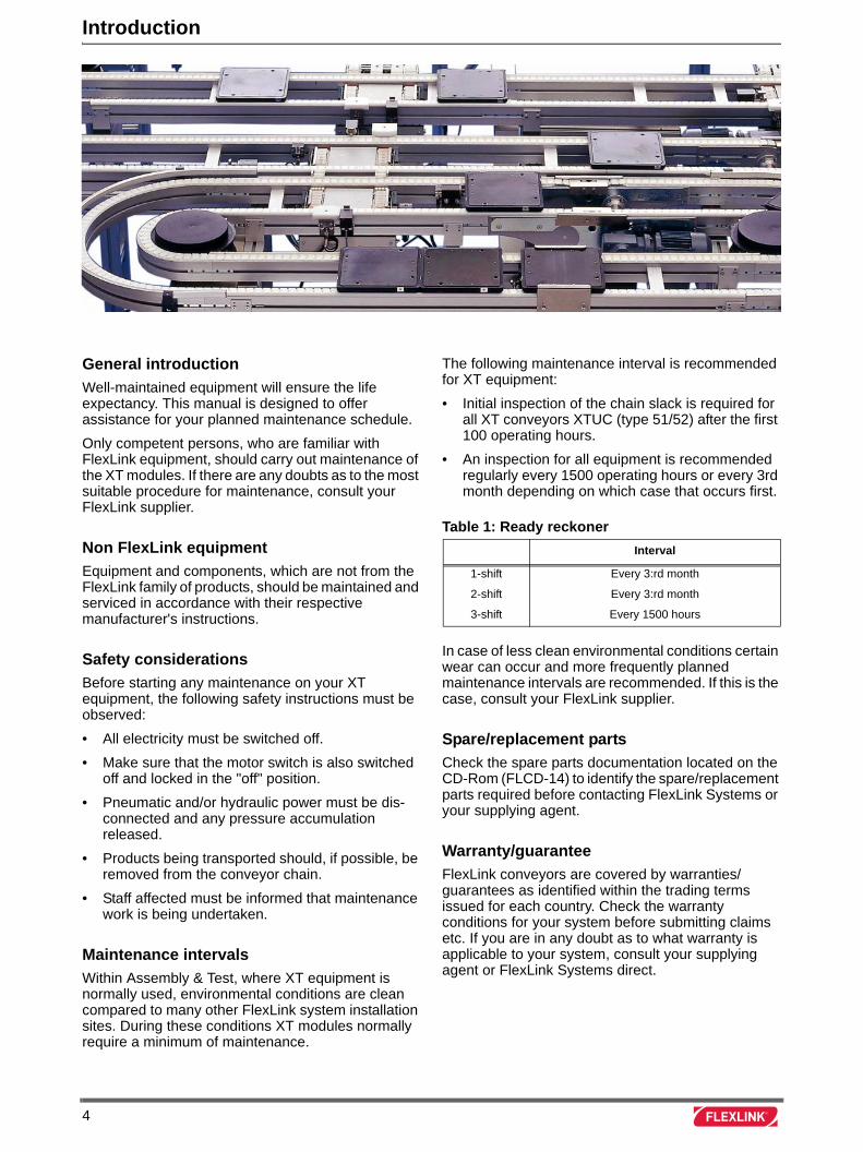
General introduction
Well-maintained equipment will ensure the life expectancy. This manual is designed to offer assistance for your planned maintenance schedule.
Only competent persons, who are familiar with FlexLink equipment, should carry out maintenance of the XT modules. If there are any doubts as to the most suitable procedure for maintenance, consult your FlexLink supplier.
Non FlexLink equipment
Equipment and components, which are not from the FlexLink family of products, should be maintained and serviced in accordance with their respective manufacturer's instructions.
Safety considerations
Before starting any maintenance on your XT equipment, the following safety instructions must be observed:
• All electricity must be switched off.
• Make sure that the motor switch is also switched off and locked in the "off" position.
• Pneumatic and/or hydraulic power must be dis-connected and any pressure accumulation released.
• Products being transported should, if possible, be removed from the conveyor chain.
• Staff affected must be informed that maintenance work is being undertaken.
Maintenance intervals
Within Assembly & Test, where XT equipment is normally used, environmental conditions are clean compared to many other FlexLink system installation sites. During these conditions XT modules normally require a minimum of maintenance.
The following maintenance interval is recommended for XT equipment:
• Initial inspection of the chain slack is required for all XT conveyors XTUC (type 51/52) after the first 100 operating hours.
• An inspection for all equipment is recommended regularly every 1500 operating hours or every 3rd month depending on which case that occurs first.
In case of less clean environmental conditions certain wear can occur and more frequently planned maintenance intervals are recommended. If this is the case, consult your FlexLink supplier.
Spare/replacement parts
Check the spare parts documentation located on the CD-Rom (FLCD-14) to identify the spare/replacement parts required before contacting FlexLink Systems or your supplying agent.
Warranty/guarantee
FlexLink conveyors are covered by warranties/ guarantees as identified within the trading terms issued for each country. Check the warranty conditions for your system before submitting claims etc. If you are in any doubt as to what warranty is applicable to your system, consult your supplying agent or FlexLink Systems direct.
Table 1: Ready reckoner
Interval
1-shift Every 3:rd month
2-shift Every 3:rd month
3-shift Every 1500 hours
4
XT Pallets XTPP
Recommended inspection interval
Inspection is recommended every 1500 operating hours or every 3rd month depending on which case that occurs first.
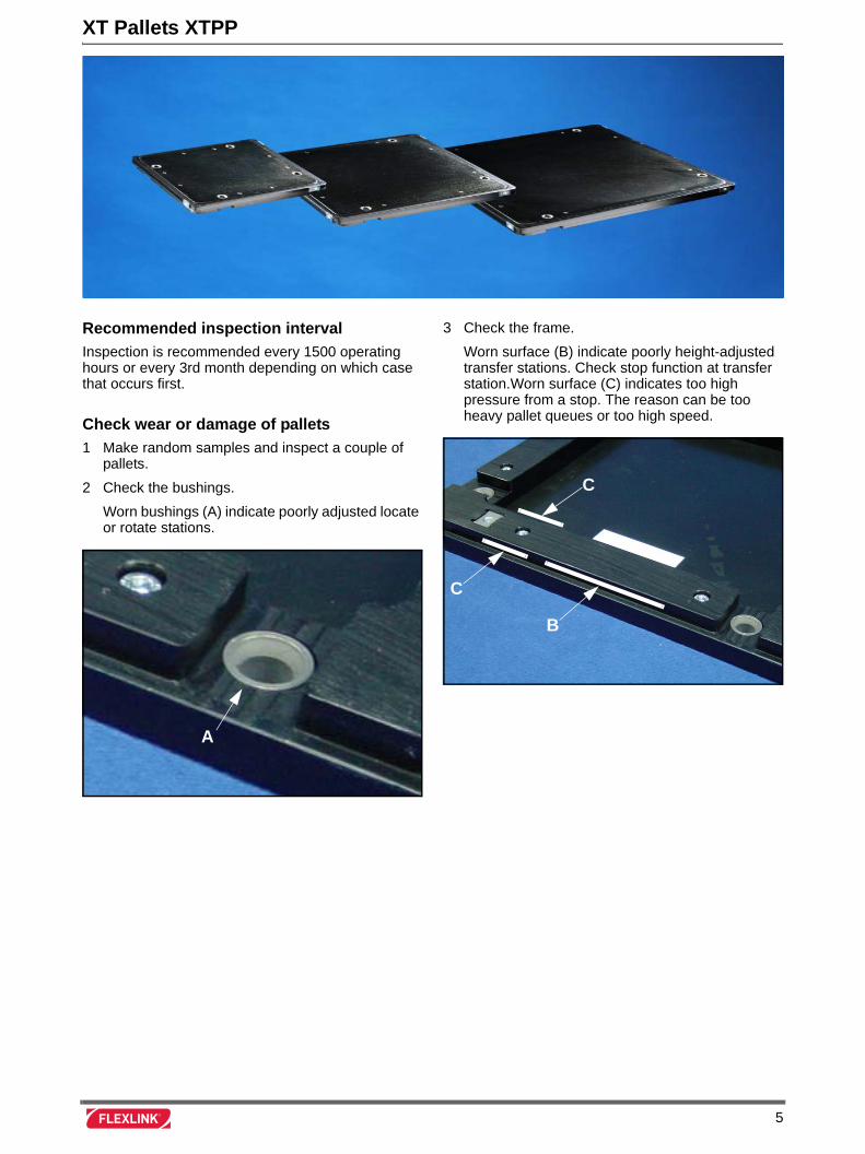
Check wear or damage of pallets
1 Make random samples and inspect a couple of pallets.
2 Check the bushings.
Worn bushings (A) indicate poorly adjusted locate or rotate stations.
3 Check the frame.
Worn surface (B) indicate poorly height-adjusted transfer stations. Check stop function at transfer station.Worn surface (C) indicates too high pressure from a stop. The reason can be too heavy pallet queues or too high speed.
A
C
C
B
5
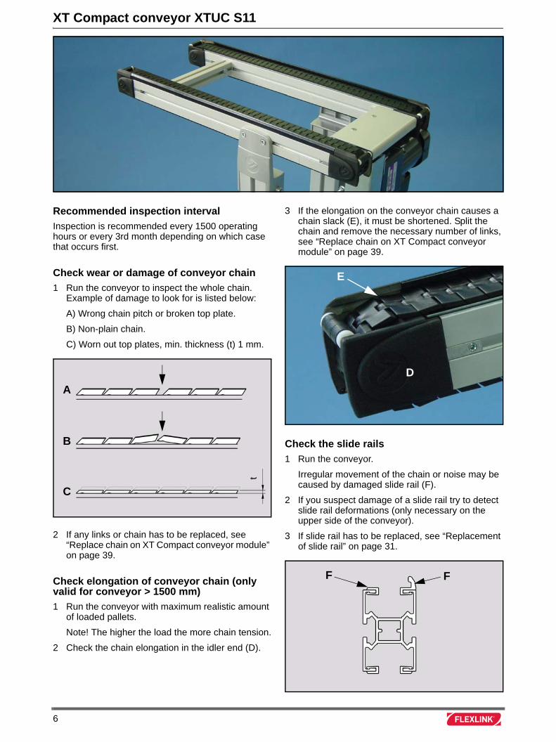
XT Compact conveyor XTUC S11
Recommended inspection interval
Inspection is recommended every 1500 operating hours or every 3rd month depending on which case that occurs first.
Check wear or damage of conveyor chain
1 Run the conveyor to inspect the whole chain. Example of damage to look for is listed below:
A) Wrong chain pitch or broken top plate.
B) Non-plain chain.
C) Worn out top plates, min. thickness (t) 1 mm.
2 If any links or chain has to be replaced, see “Replace chain on XT Compact conveyor module” on page 39.
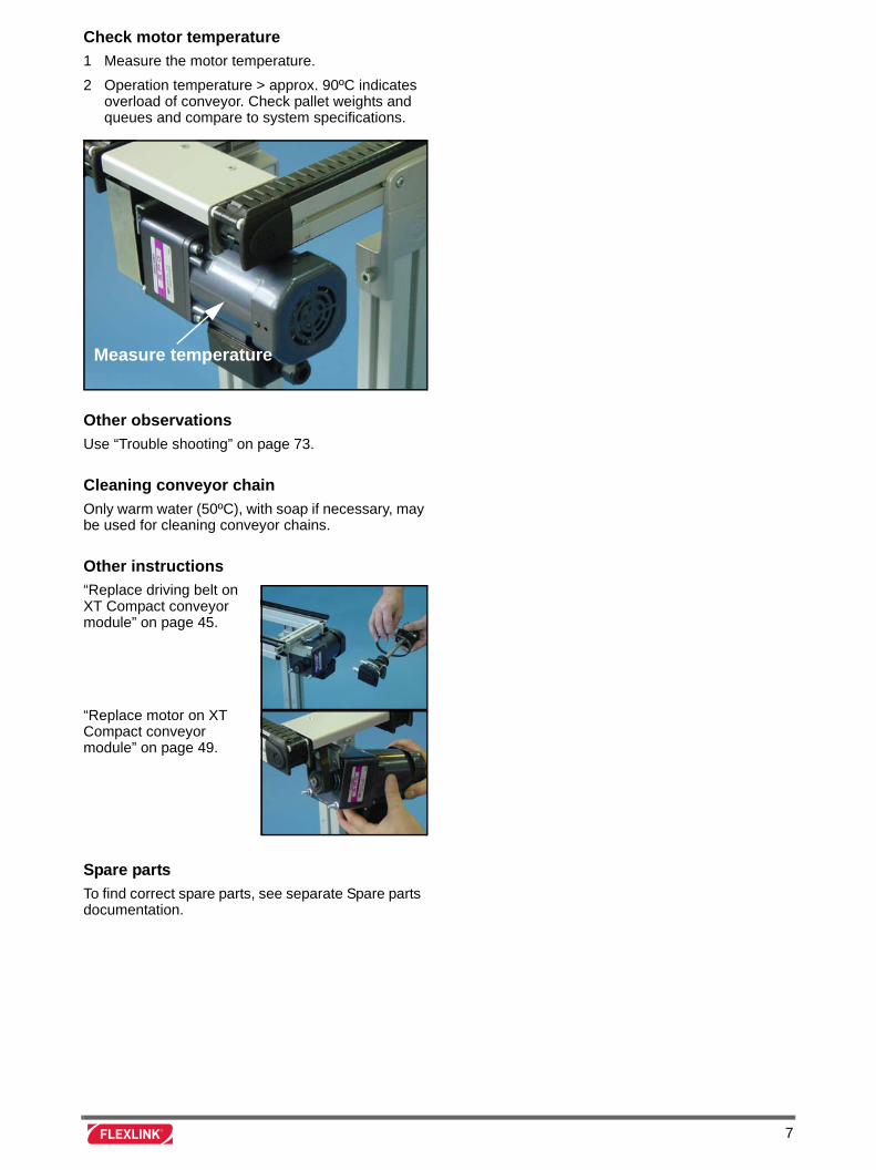
Check elongation of conveyor chain (only valid for conveyor > 1500 mm)
1 Run the conveyor with maximum realistic amount of loaded pallets.
Note! The higher the load the more chain tension.
2 Check the chain elongation in the idler end (D).
3 If the elongation on the conveyor chain causes a chain slack (E), it must be shortened. Split the chain and remove the necessary number of links, see “Replace chain on XT Compact conveyor module” on page 39.
Check the slide rails
1 Run the conveyor.
Irregular movement of the chain or noise may be caused by damaged slide rail (F).
2 If you suspect damage of a slide rail try to detect slide rail deformations (only necessary on the upper side of the conveyor).
3 If slide rail has to be replaced, see “Replacement of slide rail” on page 31.
A
C
B
t
D
E
FF
6
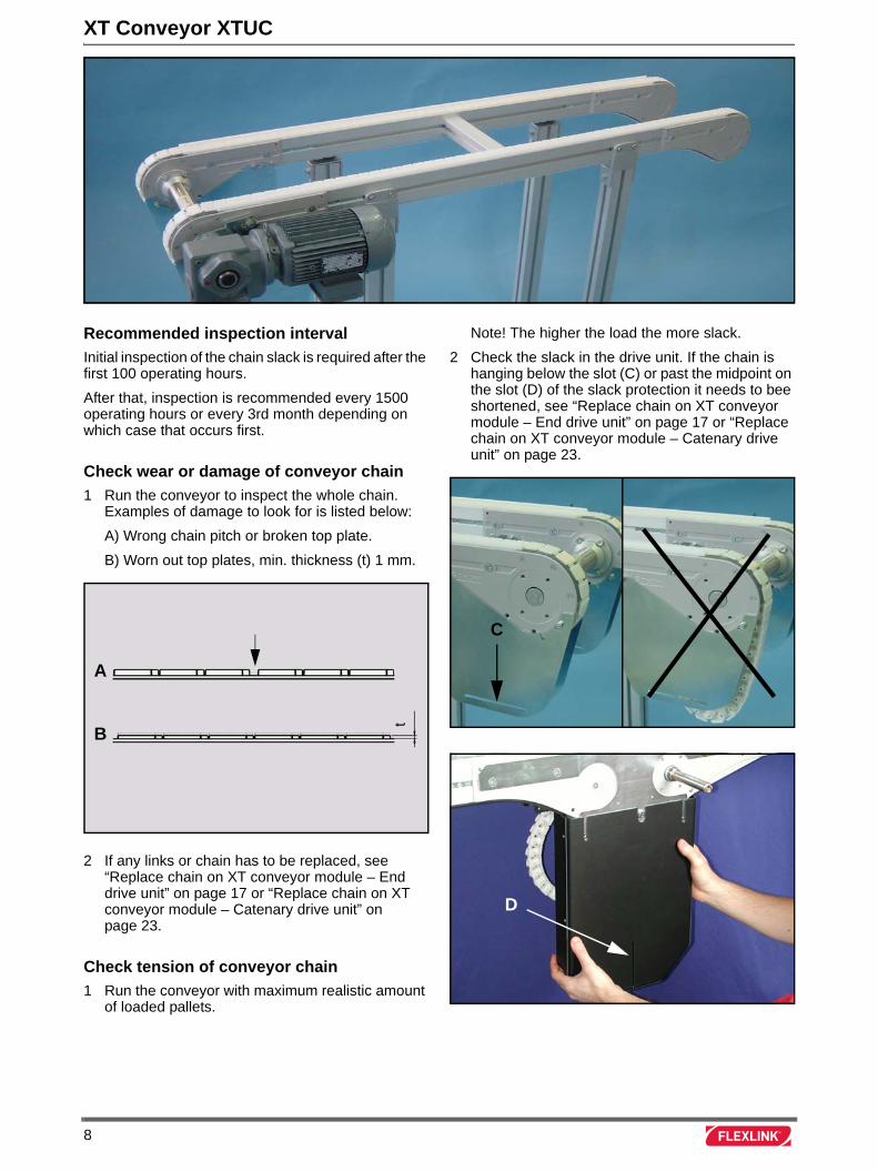
Check motor temperature
1 Measure the motor temperature.
2 Operation temperature > approx. 90ºC indicates overload of conveyor. Check pallet weights and queues and compare to system specifications.
Other observations
Use “Trouble shooting” on page 73.
Cleaning conveyor chain
Only warm water (50ºC), with soap if necessary, may be used for cleaning conveyor chains.
Other instructions
“Replace driving belt on XT Compact conveyor module” on page 45.
“Replace motor on XT Compact conveyor module” on page 49.
Spare parts
To find correct spare parts, see separate Spare parts documentation.
Measure temperature
7
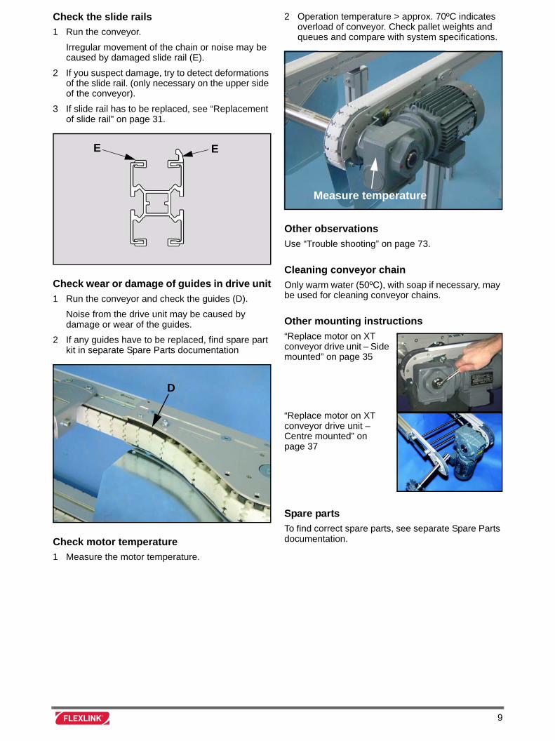
XT Conveyor XTUC
Recommended inspection interval
Initial inspection of the chain slack is required after the first 100 operating hours.
After that, inspection is recommended every 1500 operating hours or every 3rd month depending on which case that occurs first.
Check wear or damage of conveyor chain
1 Run the conveyor to inspect the whole chain. Examples of damage to look for is listed below:
A) Wrong chain pitch or broken top plate.
B) Worn out top plates, min. thickness (t) 1 mm.
2 If any links or chain has to be replaced, see “Replace chain on XT conveyor module – End drive unit” on page 17 or “Replace chain on XT conveyor module – Catenary drive unit” on page 23.
Check tension of conveyor chain
1 Run the conveyor with maximum realistic amount of loaded pallets.
Note! The higher the load the more slack.
2 Check the slack in the drive unit. If the chain is hanging below the slot (C) or past the midpoint on the slot (D) of the slack protection it needs to bee shortened, see “Replace chain on XT conveyor module – End drive unit” on page 17 or “Replace chain on XT conveyor module – Catenary drive unit” on page 23.
A
B
t
C
D
8
Check the slide rails
1 Run the conveyor.
Irregular movement of the chain or noise may be caused by damaged slide rail (E).
2 If you suspect damage, try to detect deformations of the slide rail. (only necessary on the upper side of the conveyor).
3 If slide rail has to be replaced, see “Replacement of slide rail” on page 31.
Check wear or damage of guides in drive unit
1 Run the conveyor and check the guides (D).
Noise from the drive unit may be caused by damage or wear of the guides.
2 If any guides have to be replaced, find spare part kit in separate Spare Parts documentation
.
Check motor temperature
1 Measure the motor temperature.
2 Operation temperature > approx. 70ºC indicates overload of conveyor. Check pallet weights and queues and compare with system specifications.
Other observations
Use “Trouble shooting” on page 73.
Cleaning conveyor chain
Only warm water (50ºC), with soap if necessary, may be used for cleaning conveyor chains.
Other mounting instructions
“Replace motor on XT conveyor drive unit – Side mounted” on page 35
“Replace motor on XT conveyor drive unit – Centre mounted” on page 37
Spare parts
To find correct spare parts, see separate Spare Parts documentation.
EE
D
Measure temperature
9
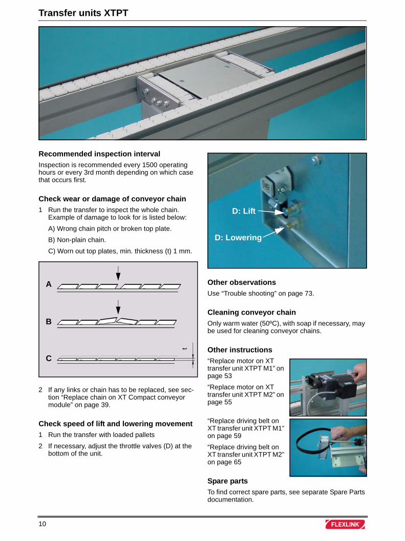
Transfer units XTPT
Recommended inspection interval
Inspection is recommended every 1500 operating hours or every 3rd month depending on which case that occurs first.
Check wear or damage of conveyor chain
1 Run the transfer to inspect the whole chain. Example of damage to look for is listed below:
A) Wrong chain pitch or broken top plate.
B) Non-plain chain.
C) Worn out top plates, min. thickness (t) 1 mm.
2 If any links or chain has to be replaced, see sec-tion “Replace chain on XT Compact conveyor module” on page 39.
Check speed of lift and lowering movement
1 Run the transfer with loaded pallets
2 If necessary, adjust the throttle valves (D) at the bottom of the unit.
Other observations
Use “Trouble shooting” on page 73.
Cleaning conveyor chain
Only warm water (50ºC), with soap if necessary, may be used for cleaning conveyor chains.
Other instructions
“Replace motor on XT transfer unit XTPT M1” on page 53
“Replace motor on XT transfer unit XTPT M2” on page 55
“Replace driving belt on XT transfer unit XTPT M1” on page 59
“Replace driving belt on XT transfer unit XTPT M2” on page 65
Spare parts
To find correct spare parts, see separate Spare Parts documentation.
A
C
B
t
D: Lowering
D: Lift
10
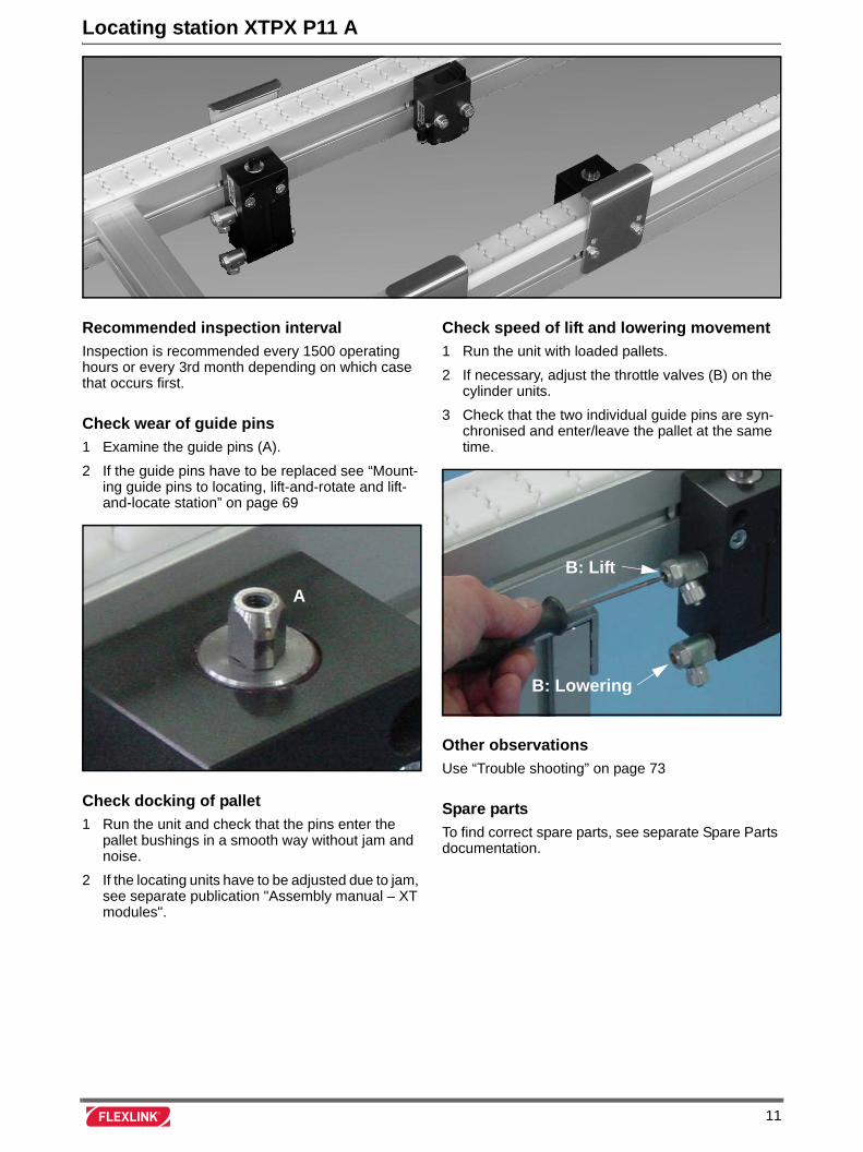
Locating station XTPX P11 A
Recommended inspection interval
Inspection is recommended every 1500 operating hours or every 3rd month depending on which case that occurs first.
Check wear of guide pins
1 Examine the guide pins (A).
2 If the guide pins have to be replaced see “Mount-ing guide pins to locating, lift-and-rotate and lift-and-locate station” on page 69
Check docking of pallet
1 Run the unit and check that the pins enter the pallet bushings in a smooth way without jam and noise.
2 If the locating units have to be adjusted due to jam, see separate publication "Assembly manual – XT modules".
Check speed of lift and lowering movement
1 Run the unit with loaded pallets.
2 If necessary, adjust the throttle valves (B) on the cylinder units.
3 Check that the two individual guide pins are syn-chronised and enter/leave the pallet at the same time.
Other observations
Use “Trouble shooting” on page 73
Spare parts
To find correct spare parts, see separate Spare Parts documentation.
A
B: Lift
B: Lowering
11
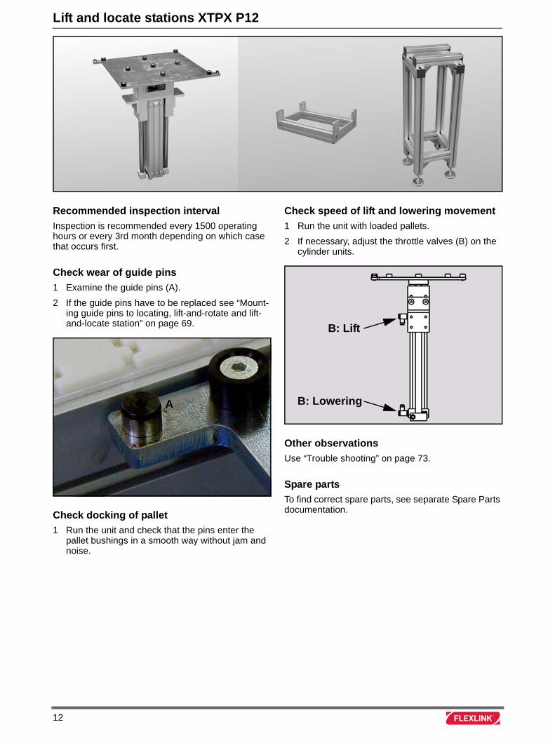
Lift and locate stations XTPX P12
Recommended inspection interval
Inspection is recommended every 1500 operating hours or every 3rd month depending on which case that occurs first.
Check wear of guide pins
1 Examine the guide pins (A).
2 If the guide pins have to be replaced see “Mount-ing guide pins to locating, lift-and-rotate and lift-and-locate station” on page 69.
Check docking of pallet
1 Run the unit and check that the pins enter the pallet bushings in a smooth way without jam and noise.
Check speed of lift and lowering movement
1 Run the unit with loaded pallets.
2 If necessary, adjust the throttle valves (B) on the cylinder units.
Other observations
Use “Trouble shooting” on page 73.
Spare parts
To find correct spare parts, see separate Spare Parts documentation.
A
B: Lift
B: Lowering
12
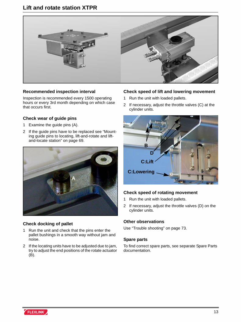
Lift and rotate station XTPR
Recommended inspection interval
Inspection is recommended every 1500 operating hours or every 3rd month depending on which case that occurs first.
Check wear of guide pins
1 Examine the guide pins (A).
2 If the guide pins have to be replaced see “Mount-ing guide pins to locating, lift-and-rotate and lift-and-locate station” on page 69.
Check docking of pallet
1 Run the unit and check that the pins enter the pallet bushings in a smooth way without jam and noise.
2 If the locating units have to be adjusted due to jam, try to adjust the end positions of the rotate actuator (B).
Check speed of lift and lowering movement
1 Run the unit with loaded pallets.
2 If necessary, adjust the throttle valves (C) at the cylinder units.
Check speed of rotating movement
1 Run the unit with loaded pallets.
2 If necessary, adjust the throttle valves (D) on the cylinder units.
Other observations
Use “Trouble shooting” on page 73.
Spare parts
To find correct spare parts, see separate Spare Parts documentation.
A
B
D
C:Lift
C:Lowering
13
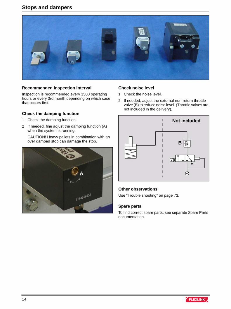
Stops and dampers
Recommended inspection interval
Inspection is recommended every 1500 operating hours or every 3rd month depending on which case that occurs first.
Check the damping function
1 Check the damping function.
2 If needed, fine adjust the damping function (A) when the system is running.
CAUTION! Heavy pallets in combination with an over damped stop can damage the stop.
Check noise level
1 Check the noise level.
2 If needed, adjust the external non-return throttle valve (B) to reduce noise level. (Throttle valves are not included in the delivery).
Other observations
Use “Trouble shooting” on page 73.
Spare parts
To find correct spare parts, see separate Spare Parts documentation.
A
Not included
B
14

Mounting instructions
15

16
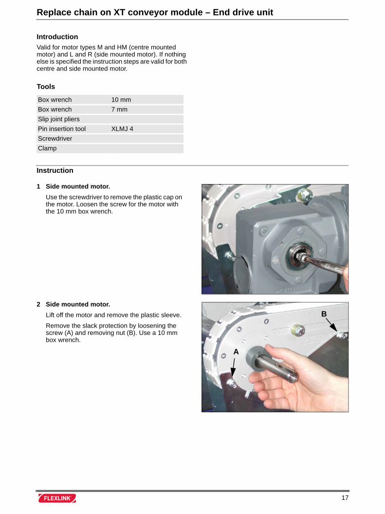
Replace chain on XT conveyor module – End drive unit
Introduction
Valid for motor types M and HM (centre mounted motor) and L and R (side mounted motor). If nothing else is specified the instruction steps are valid for both centre and side mounted motor.
Tools
Instruction
Box wrench 10 mm
Box wrench 7 mm
Slip joint pliers
Pin insertion tool XLMJ 4
Screwdriver
Clamp
1 Side mounted motor.
Use the screwdriver to remove the plastic cap on the motor. Loosen the screw for the motor with the 10 mm box wrench.
2 Side mounted motor.
Lift off the motor and remove the plastic sleeve.
Remove the slack protection by loosening the screw (A) and removing nut (B). Use a 10 mm box wrench.
A
B
17
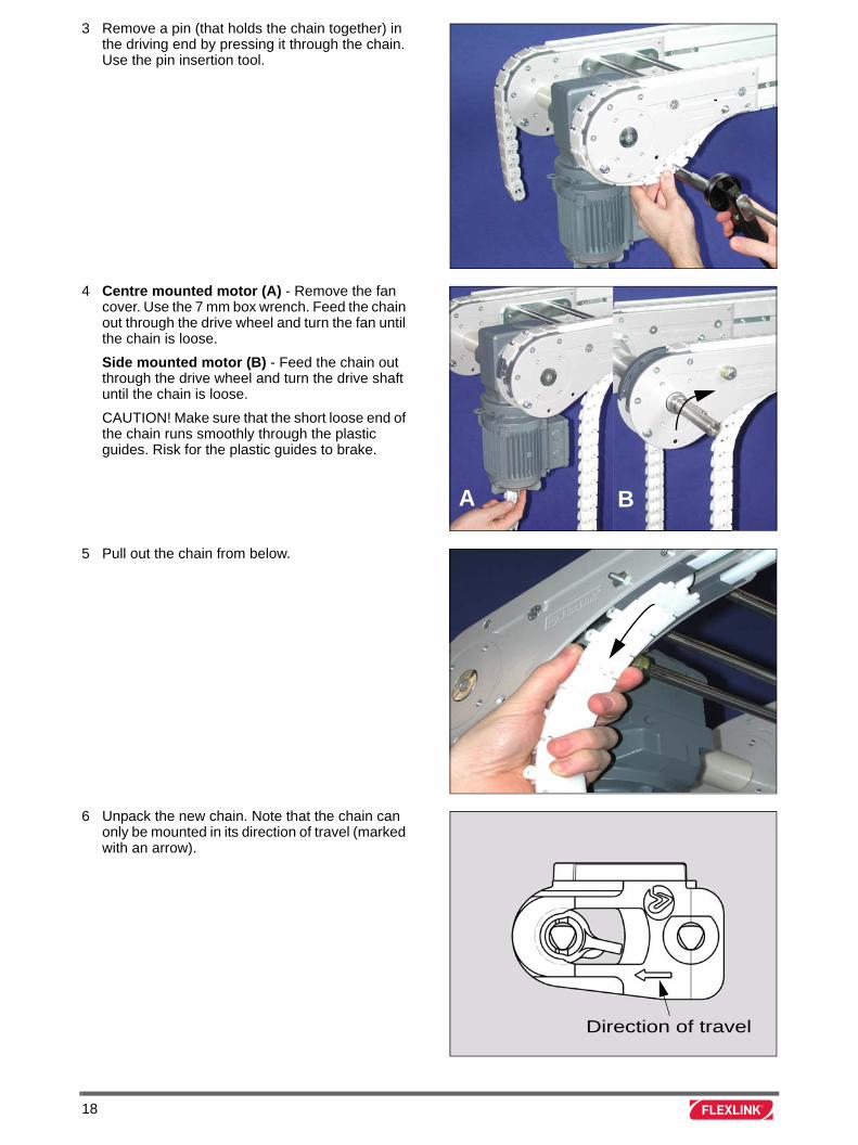
3 Remove a pin (that holds the chain together) in the driving end by pressing it through the chain. Use the pin insertion tool.
4 Centre mounted motor (A) - Remove the fan cover. Use the 7 mm box wrench. Feed the chain out through the drive wheel and turn the fan until the chain is loose.
Side mounted motor (B) - Feed the chain out through the drive wheel and turn the drive shaft until the chain is loose.
CAUTION! Make sure that the short loose end of the chain runs smoothly through the plastic guides. Risk for the plastic guides to brake.
5 Pull out the chain from below.
6 Unpack the new chain. Note that the chain can only be mounted in its direction of travel (marked with an arrow).
BA
Direction of travel
18
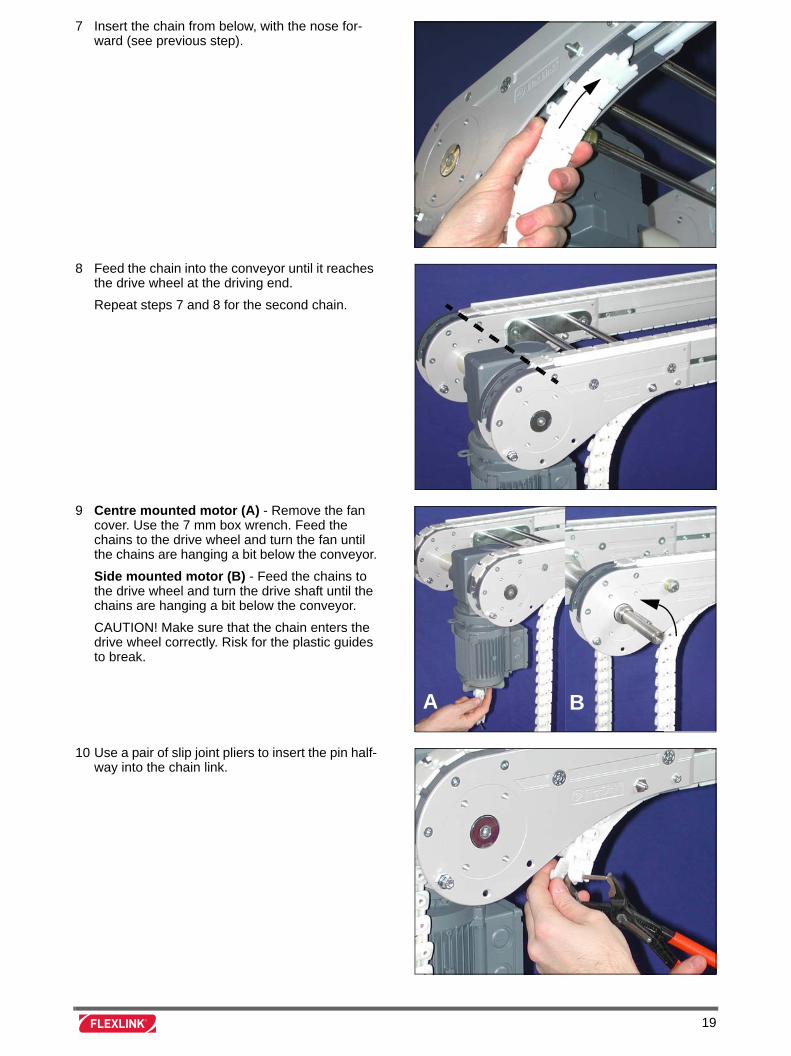
7 Insert the chain from below, with the nose for-ward (see previous step).
8 Feed the chain into the conveyor until it reaches the drive wheel at the driving end.
Repeat steps 7 and 8 for the second chain.
9 Centre mounted motor (A) - Remove the fan cover. Use the 7 mm box wrench. Feed the chains to the drive wheel and turn the fan until the chains are hanging a bit below the conveyor.
Side mounted motor (B) - Feed the chains to the drive wheel and turn the drive shaft until the chains are hanging a bit below the conveyor.
CAUTION! Make sure that the chain enters the drive wheel correctly. Risk for the plastic guides to break.
10 Use a pair of slip joint pliers to insert the pin half-way into the chain link.
BA
19
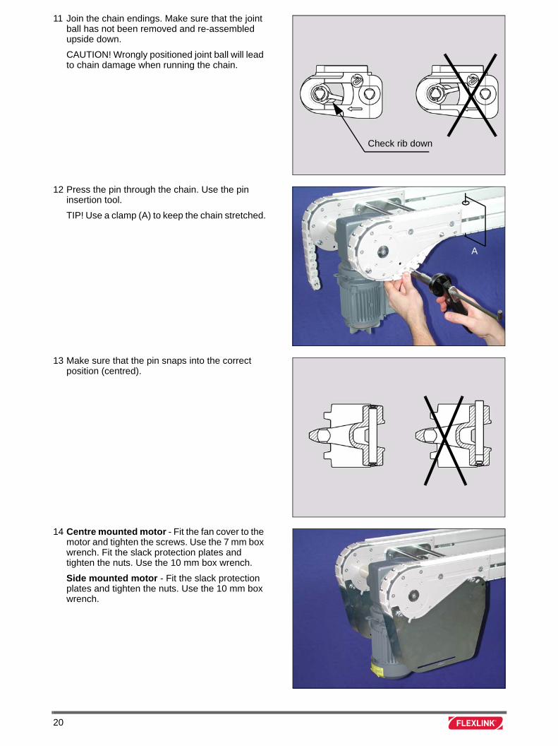
11 Join the chain endings. Make sure that the joint ball has not been removed and re-assembled upside down.
CAUTION! Wrongly positioned joint ball will lead to chain damage when running the chain.
12 Press the pin through the chain. Use the pin insertion tool.
TIP! Use a clamp (A) to keep the chain stretched.
13 Make sure that the pin snaps into the correct position (centred).
14 Centre mounted motor - Fit the fan cover to the motor and tighten the screws. Use the 7 mm box wrench. Fit the slack protection plates and tighten the nuts. Use the 10 mm box wrench.
Side mounted motor - Fit the slack protection plates and tighten the nuts. Use the 10 mm box wrench.
Check rib down
A
20
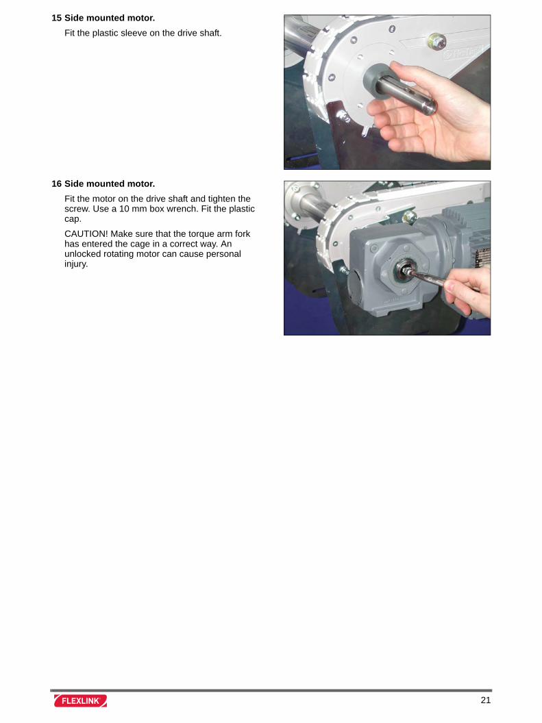
15 Side mounted motor.
Fit the plastic sleeve on the drive shaft.
16 Side mounted motor.
Fit the motor on the drive shaft and tighten the screw. Use a 10 mm box wrench. Fit the plastic cap.
CAUTION! Make sure that the torque arm fork has entered the cage in a correct way. An unlocked rotating motor can cause personal injury.
21

22
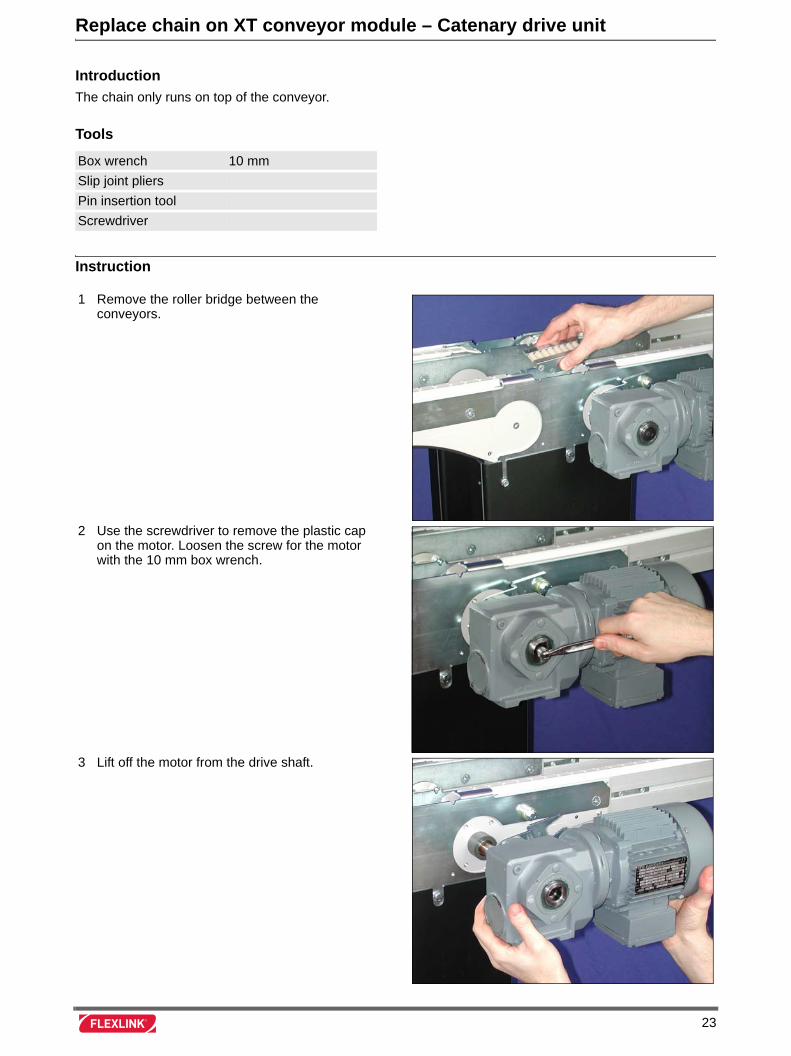
Replace chain on XT conveyor module – Catenary drive unit
Introduction
The chain only runs on top of the conveyor.
Tools
Instruction
Box wrench 10 mm
Slip joint pliers
Pin insertion tool
Screwdriver
1 Remove the roller bridge between the conveyors.
2 Use the screwdriver to remove the plastic cap on the motor. Loosen the screw for the motor with the 10 mm box wrench.
3 Lift off the motor from the drive shaft.
23
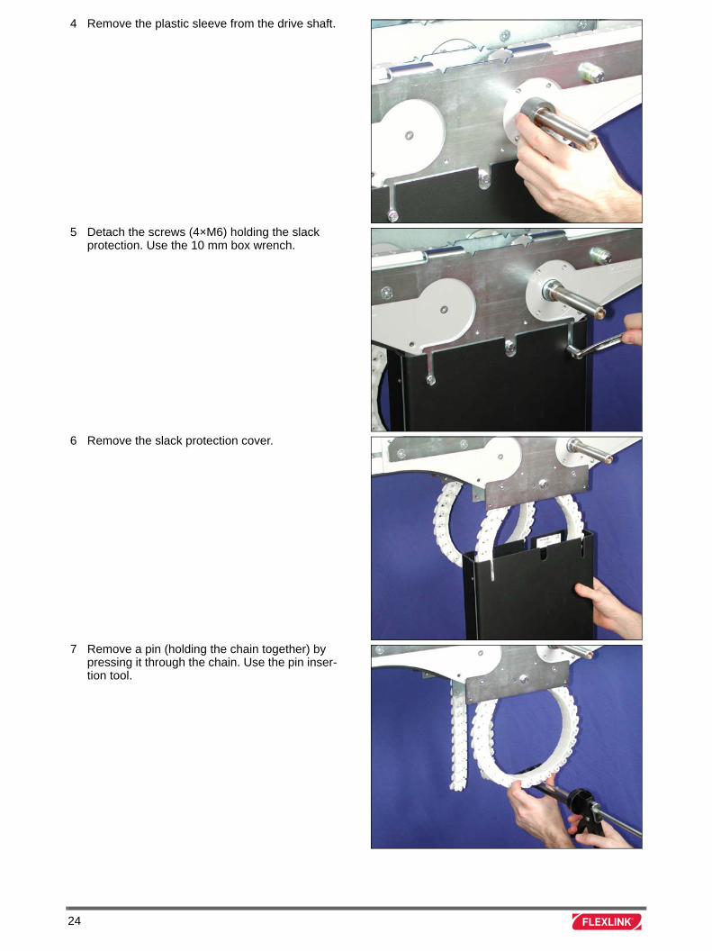
4 Remove the plastic sleeve from the drive shaft.
5 Detach the screws (4×M6) holding the slack protection. Use the 10 mm box wrench.
6 Remove the slack protection cover.
7 Remove a pin (holding the chain together) by pressing it through the chain. Use the pin inser-tion tool.
24
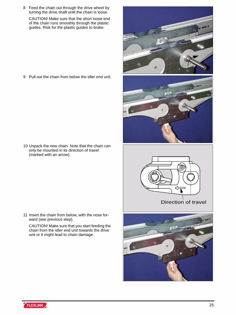
8 Feed the chain out through the drive wheel by turning the drive shaft until the chain is loose.
CAUTION! Make sure that the short loose end of the chain runs smoothly through the plastic guides. Risk for the plastic guides to brake.
9 Pull out the chain from below the idler end unit.
10 Unpack the new chain. Note that the chain can only be mounted in its direction of travel (marked with an arrow).
11 Insert the chain from below, with the nose for-ward (see previous step).
CAUTION! Make sure that you start feeding the chain from the idler end unit towards the drive unit or it might lead to chain damage.
Direction of travel
25
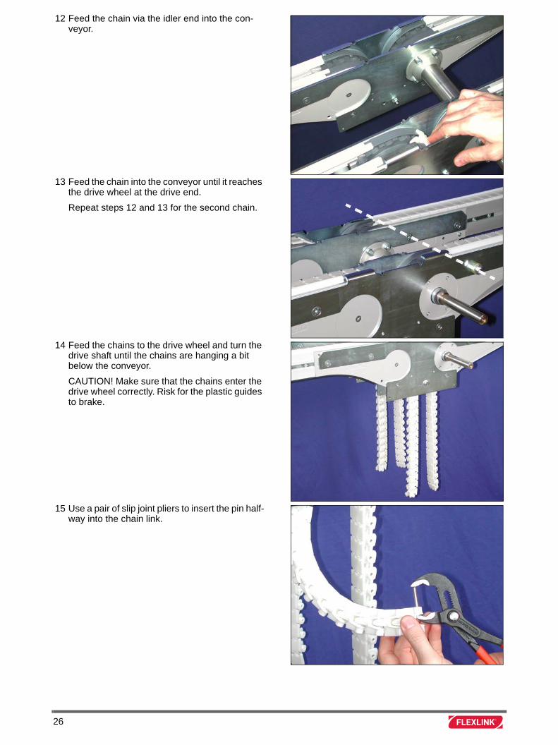
12 Feed the chain via the idler end into the con-veyor.
13 Feed the chain into the conveyor until it reaches the drive wheel at the drive end.
Repeat steps 12 and 13 for the second chain.
14 Feed the chains to the drive wheel and turn the drive shaft until the chains are hanging a bit below the conveyor.
CAUTION! Make sure that the chains enter the drive wheel correctly. Risk for the plastic guides to brake.
15 Use a pair of slip joint pliers to insert the pin half-way into the chain link.
26
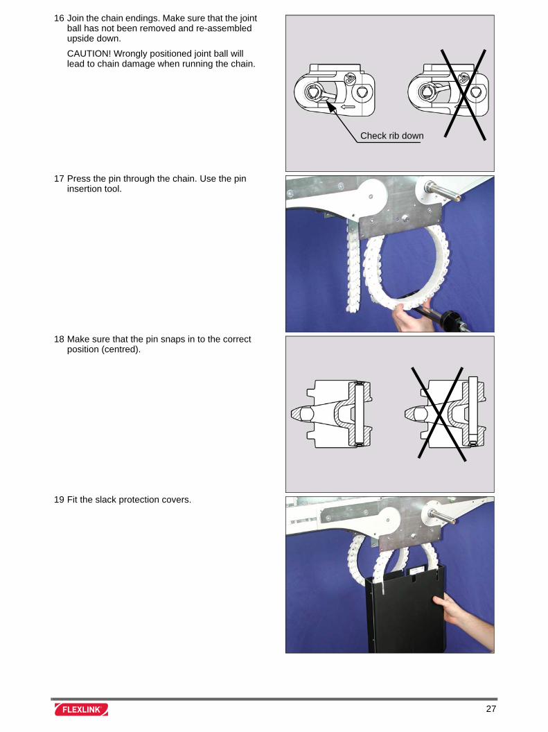
16 Join the chain endings. Make sure that the joint ball has not been removed and re-assembled upside down.
CAUTION! Wrongly positioned joint ball will lead to chain damage when running the chain.
17 Press the pin through the chain. Use the pin insertion tool.
18 Make sure that the pin snaps in to the correct position (centred).
19 Fit the slack protection covers.
Check rib down
27
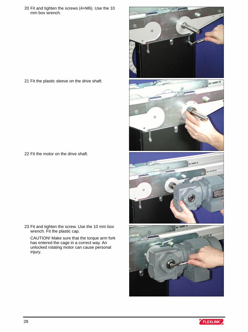
20 Fit and tighten the screws (4×M6). Use the 10 mm box wrench.
21 Fit the plastic sleeve on the drive shaft.
22 Fit the motor on the drive shaft.
23 Fit and tighten the screw. Use the 10 mm box wrench. Fit the plastic cap.
CAUTION! Make sure that the torque arm fork has entered the cage in a correct way. An unlocked rotating motor can cause personal injury.
28
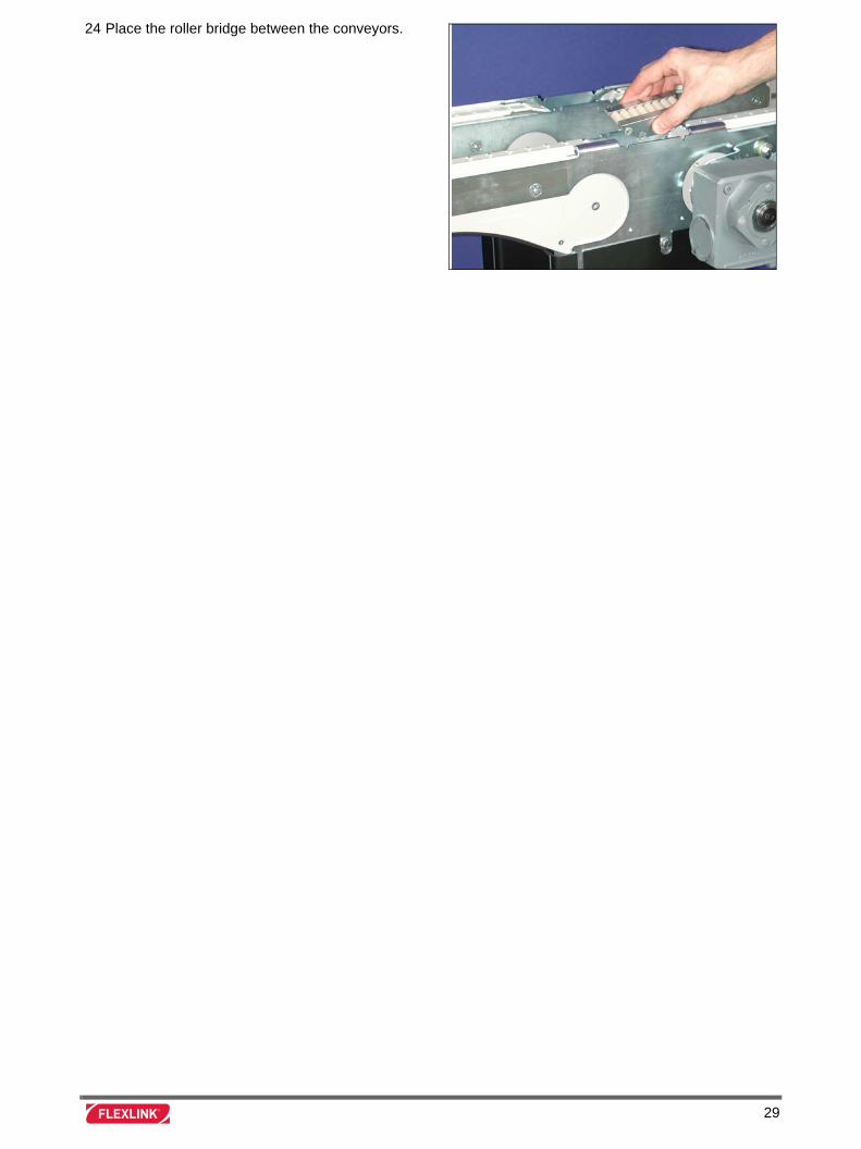
24 Place the roller bridge between the conveyors.
29

30
Replacement of slide rail
Introduction
This instruction is primarily intended for conveyor XT, but can also be used as a guideline for the XT Compact conveyor.
Tools
Instruction
Allen key 4 mm
Drilling machine
Drill 3,2 mm
Screwdriver
File
Drill fixture tool 3923584
Countersink tool
Rivet tool 3923563
Cutting pliers
Marker
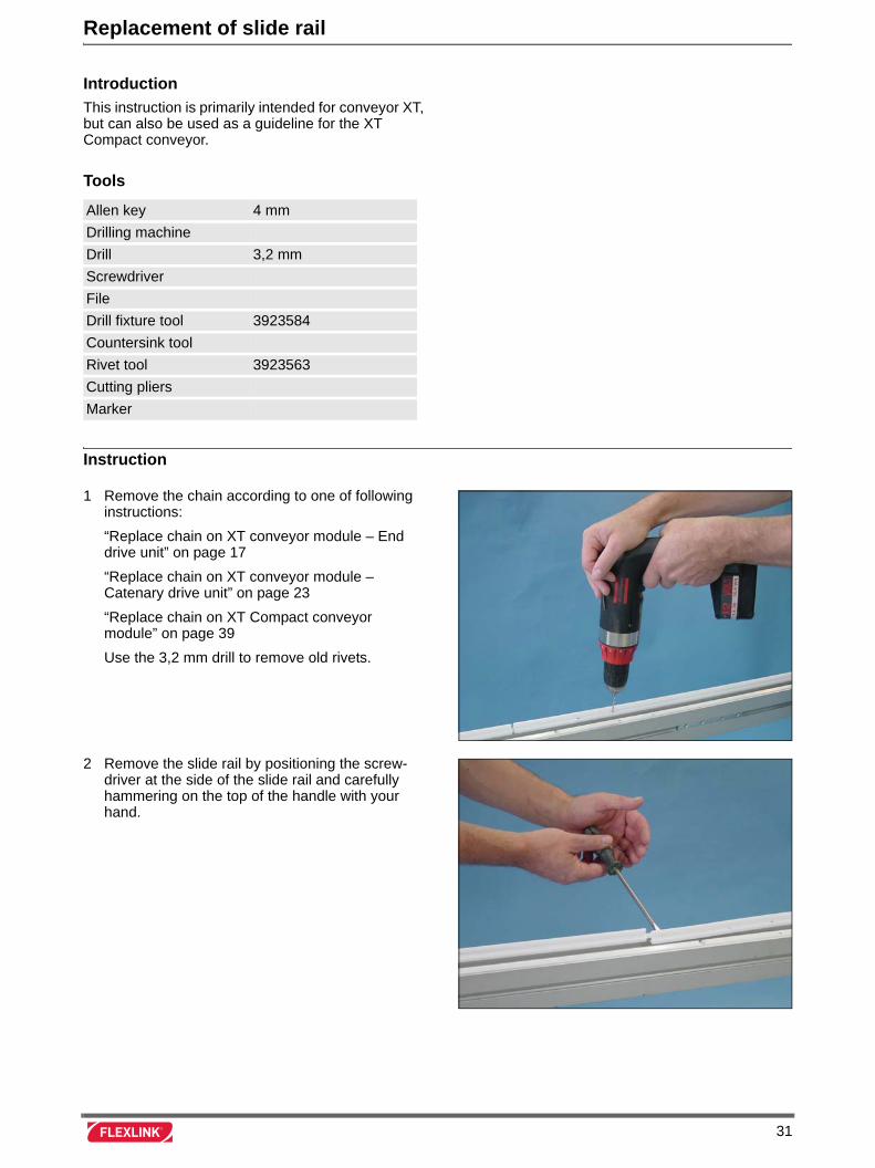
1 Remove the chain according to one of following instructions:
“Replace chain on XT conveyor module – End drive unit” on page 17
“Replace chain on XT conveyor module – Catenary drive unit” on page 23
“Replace chain on XT Compact conveyor module” on page 39
Use the 3,2 mm drill to remove old rivets.
2 Remove the slide rail by positioning the screw-driver at the side of the slide rail and carefully hammering on the top of the handle with your hand.
31
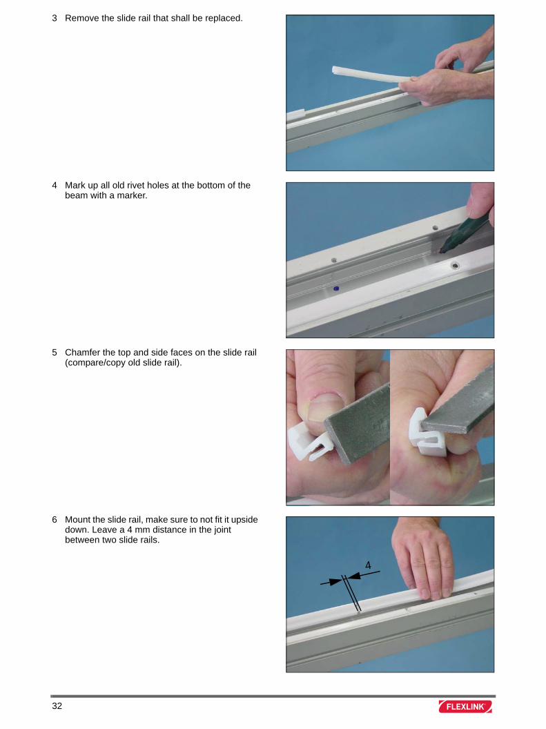
3 Remove the slide rail that shall be replaced.
4 Mark up all old rivet holes at the bottom of the beam with a marker.
5 Chamfer the top and side faces on the slide rail (compare/copy old slide rail).
6 Mount the slide rail, make sure to not fit it upside down. Leave a 4 mm distance in the joint between two slide rails.
4
32
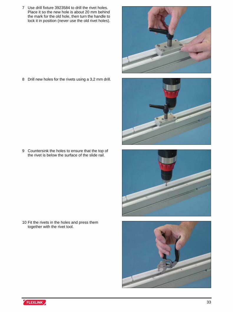
7 Use drill fixture 3923584 to drill the rivet holes. Place it so the new hole is about 20 mm behind the mark for the old hole, then turn the handle to lock it in position (never use the old rivet holes).
8 Drill new holes for the rivets using a 3,2 mm drill.
9 Countersink the holes to ensure that the top of the rivet is below the surface of the slide rail.
10 Fit the rivets in the holes and press them together with the rivet tool.
33
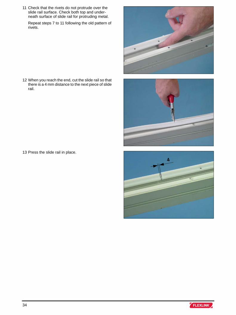
11 Check that the rivets do not protrude over the slide rail surface. Check both top and under-neath surface of slide rail for protruding metal.
Repeat steps 7 to 11 following the old pattern of rivets.
12 When you reach the end, cut the slide rail so that there is a 4 mm distance to the next piece of slide rail.
13 Press the slide rail in place.
4
34
Replace motor on XT conveyor drive unit – Side mounted
Introduction
Valid for motor types L and R (side mounted motor).
Tools
Instruction
Box wrench 10 mm
Box wrench 13 mm
Screwdriver
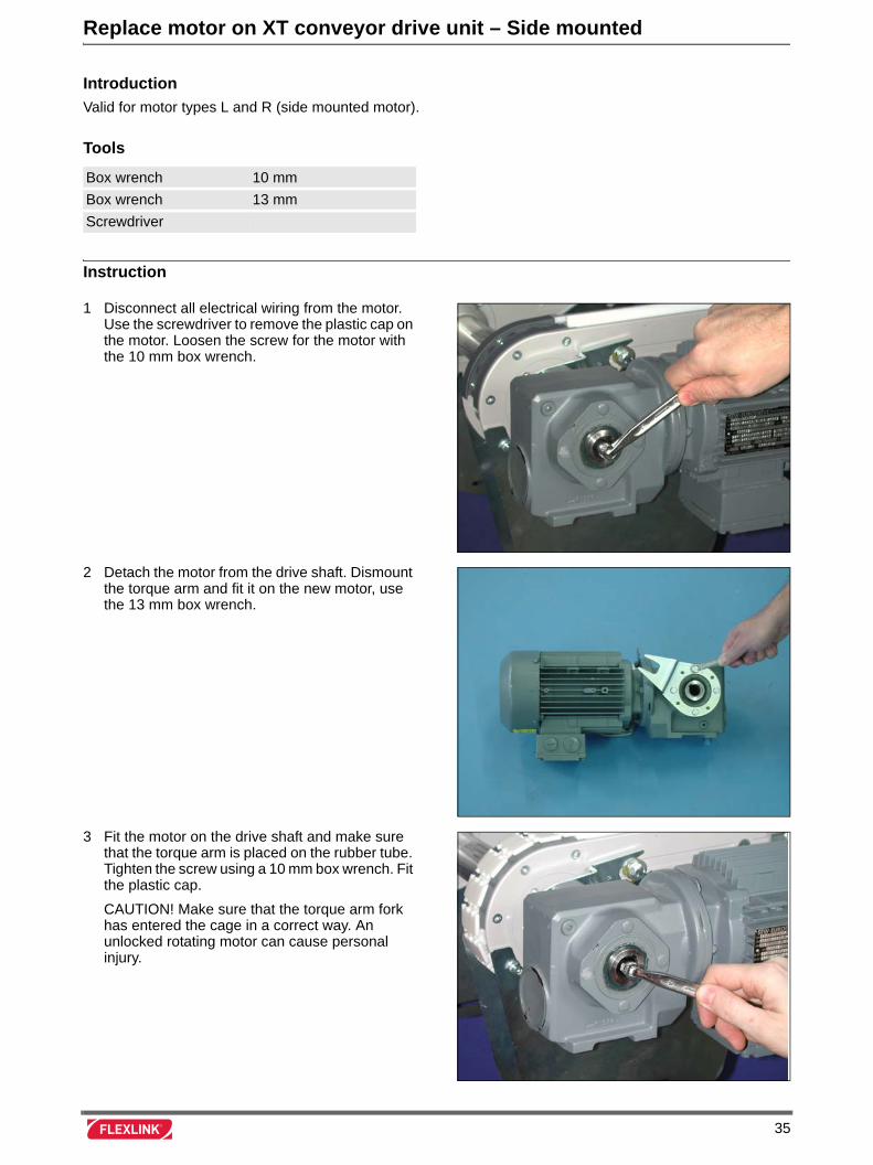
1 Disconnect all electrical wiring from the motor. Use the screwdriver to remove the plastic cap on the motor. Loosen the screw for the motor with the 10 mm box wrench.
2 Detach the motor from the drive shaft. Dismount the torque arm and fit it on the new motor, use the 13 mm box wrench.
3 Fit the motor on the drive shaft and make sure that the torque arm is placed on the rubber tube. Tighten the screw using a 10 mm box wrench. Fit the plastic cap.
CAUTION! Make sure that the torque arm fork has entered the cage in a correct way. An unlocked rotating motor can cause personal injury.
35

36
Replace motor on XT conveyor drive unit – Centre mounted
Introduction
Valid for motor types M and HM (centre mounted motor).
Tools
Instruction
Allen key 5 mm
Retaining ring plier
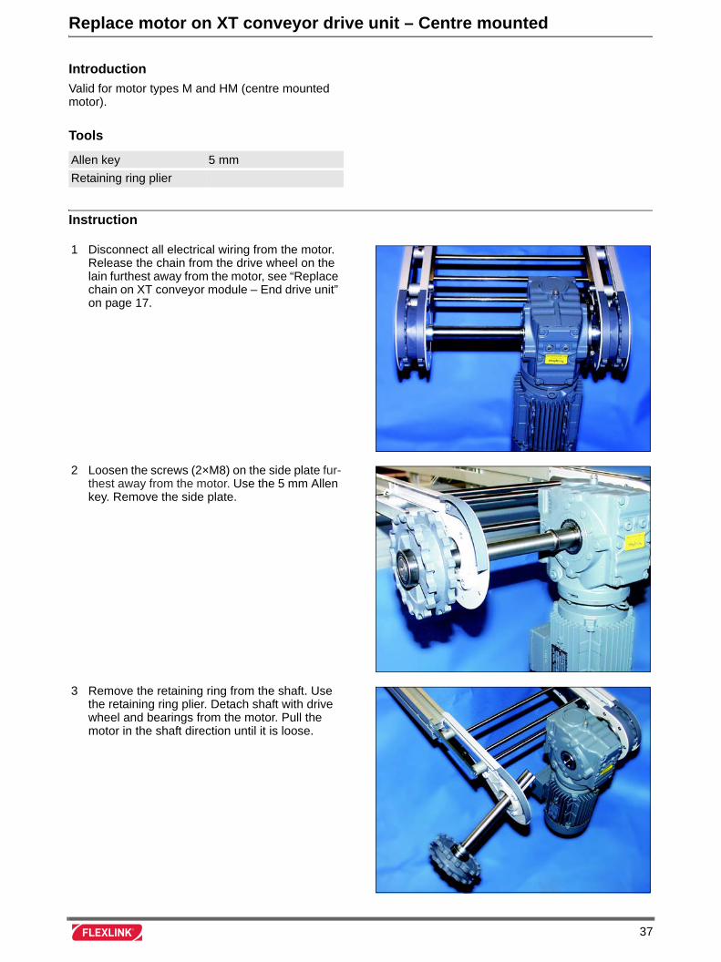
1 Disconnect all electrical wiring from the motor. Release the chain from the drive wheel on the lain furthest away from the motor, see “Replace chain on XT conveyor module – End drive unit” on page 17.
2 Loosen the screws (2×M8) on the side plate fur-thest away from the motor. Use the 5 mm Allen key. Remove the side plate.
3 Remove the retaining ring from the shaft. Use the retaining ring plier. Detach shaft with drive wheel and bearings from the motor. Pull the motor in the shaft direction until it is loose.
37
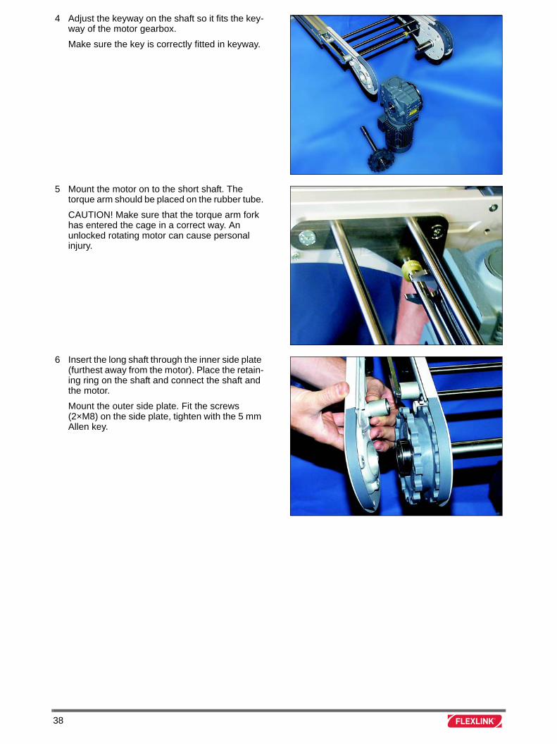
4 Adjust the keyway on the shaft so it fits the key-way of the motor gearbox.
Make sure the key is correctly fitted in keyway.
5 Mount the motor on to the short shaft. The torque arm should be placed on the rubber tube.
CAUTION! Make sure that the torque arm fork has entered the cage in a correct way. An unlocked rotating motor can cause personal injury.
6 Insert the long shaft through the inner side plate (furthest away from the motor). Place the retain-ing ring on the shaft and connect the shaft and the motor.
Mount the outer side plate. Fit the screws (2×M8) on the side plate, tighten with the 5 mm Allen key.
38
Replace chain on XT Compact conveyor module
Introduction
Valid for XT Compact conveyor only.
Tools
Instruction
Screwdriver
Allen key 3 mm
Allen key 2,5 mm
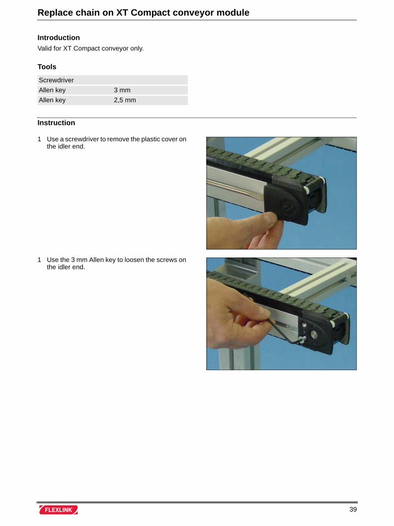
1 Use a screwdriver to remove the plastic cover on the idler end.
1 Use the 3 mm Allen key to loosen the screws on the idler end.
39
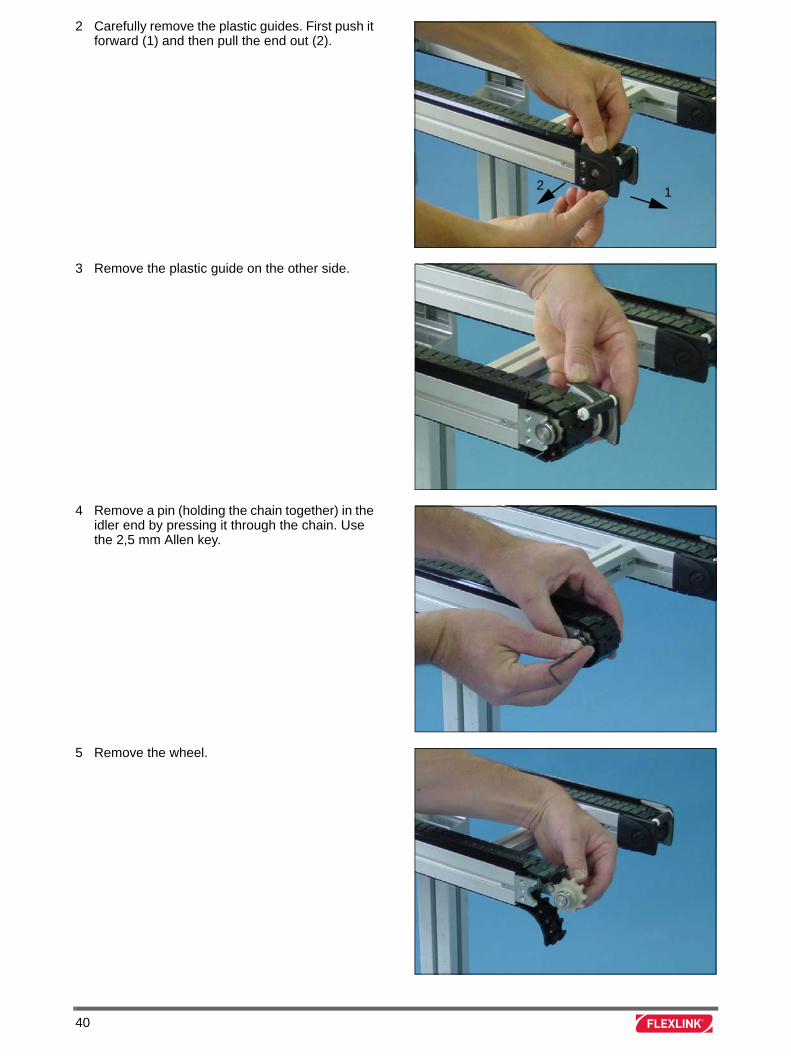
2 Carefully remove the plastic guides. First push it forward (1) and then pull the end out (2).
3 Remove the plastic guide on the other side.
4 Remove a pin (holding the chain together) in the idler end by pressing it through the chain. Use the 2,5 mm Allen key.
5 Remove the wheel.
12
40
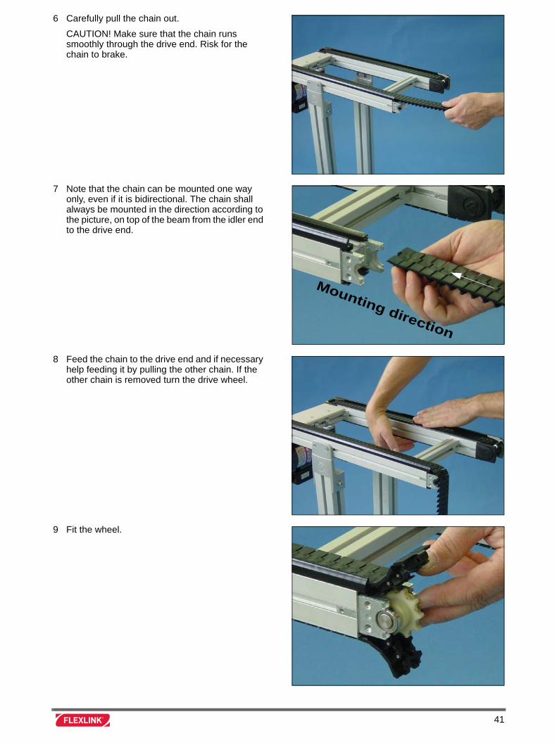
6 Carefully pull the chain out.
CAUTION! Make sure that the chain runs smoothly through the drive end. Risk for the chain to brake.
7 Note that the chain can be mounted one way only, even if it is bidirectional. The chain shall always be mounted in the direction according to the picture, on top of the beam from the idler end to the drive end.
8 Feed the chain to the drive end and if necessary help feeding it by pulling the other chain. If the other chain is removed turn the drive wheel.
9 Fit the wheel.
Mounting direction
41
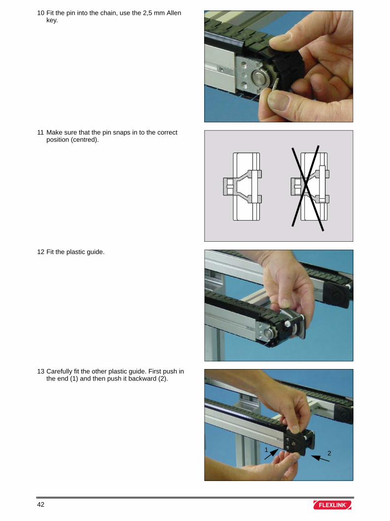
10 Fit the pin into the chain, use the 2,5 mm Allen key.
11 Make sure that the pin snaps in to the correct position (centred).
12 Fit the plastic guide.
13 Carefully fit the other plastic guide. First push in the end (1) and then push it backward (2).
21
42
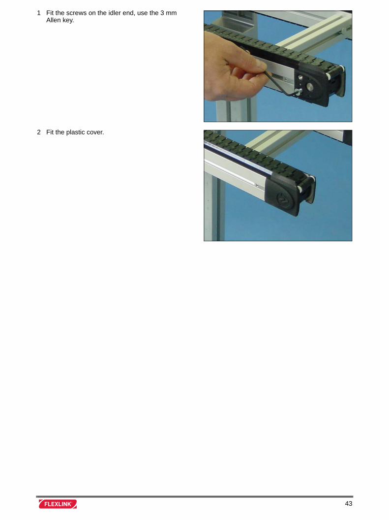
1 Fit the screws on the idler end, use the 3 mm Allen key.
2 Fit the plastic cover.
43

44
Replace driving belt on XT Compact conveyor module
Introduction
Valid for XT Compact conveyor only.
Tools
Instruction
Box wrench 8 mm
Allen key 3 mm
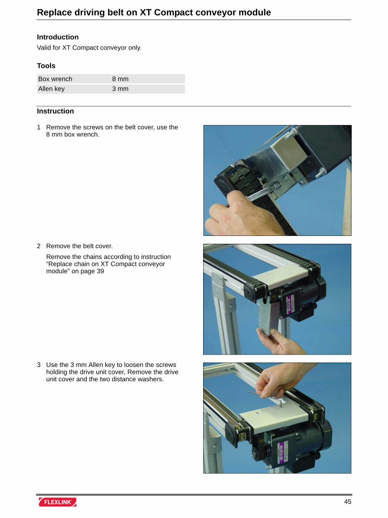
1 Remove the screws on the belt cover, use the 8 mm box wrench.
2 Remove the belt cover.
Remove the chains according to instruction “Replace chain on XT Compact conveyor module” on page 39
3 Use the 3 mm Allen key to loosen the screws holding the drive unit cover, Remove the drive unit cover and the two distance washers.
45
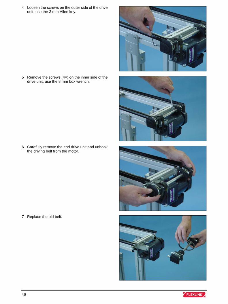
4 Loosen the screws on the outer side of the drive unit, use the 3 mm Allen key.
5 Remove the screws (4×) on the inner side of the drive unit, use the 8 mm box wrench.
6 Carefully remove the end drive unit and unhook the driving belt from the motor.
7 Replace the old belt.
46
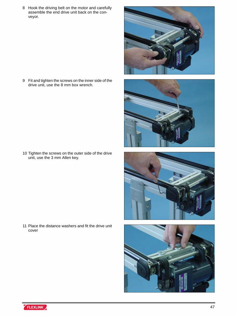
8 Hook the driving belt on the motor and carefully assemble the end drive unit back on the con-veyor.
9 Fit and tighten the screws on the inner side of the drive unit, use the 8 mm box wrench.
10 Tighten the screws on the outer side of the drive unit, use the 3 mm Allen key.
11 Place the distance washers and fit the drive unit cover
47
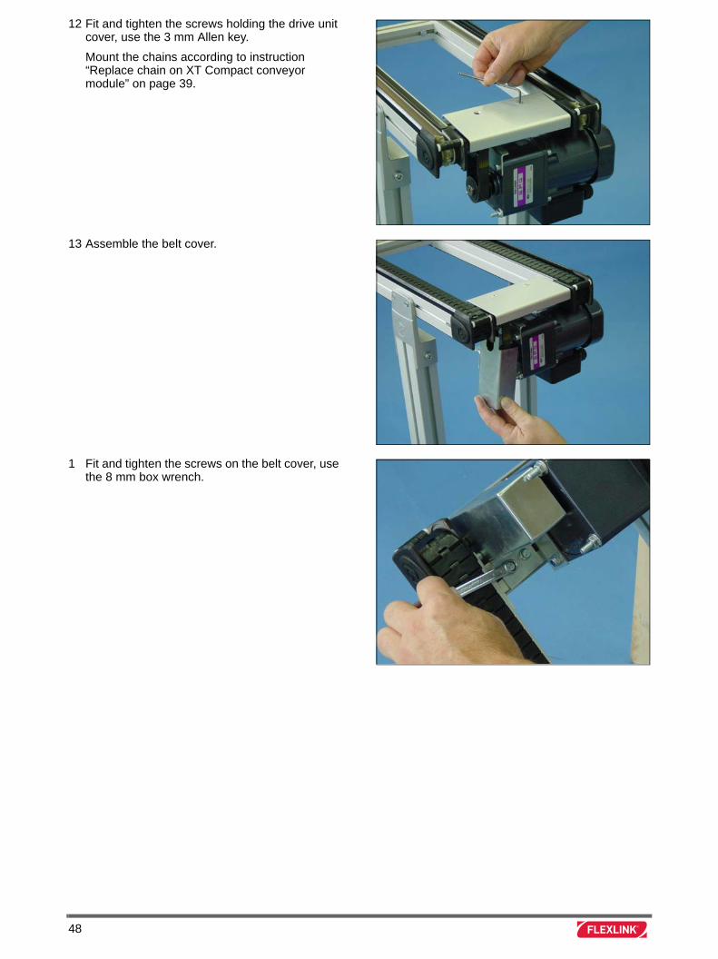
12 Fit and tighten the screws holding the drive unit cover, use the 3 mm Allen key.
Mount the chains according to instruction “Replace chain on XT Compact conveyor module” on page 39.
13 Assemble the belt cover.
1 Fit and tighten the screws on the belt cover, use the 8 mm box wrench.
48
Replace motor on XT Compact conveyor module
Introduction
Valid for XT Compact conveyor only.
Tools
Instruction
Box wrench 10 mm
Box wrench 8 mm
Allen key 5 mm
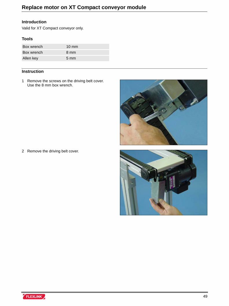
1 Remove the screws on the driving belt cover. Use the 8 mm box wrench.
2 Remove the driving belt cover.
49
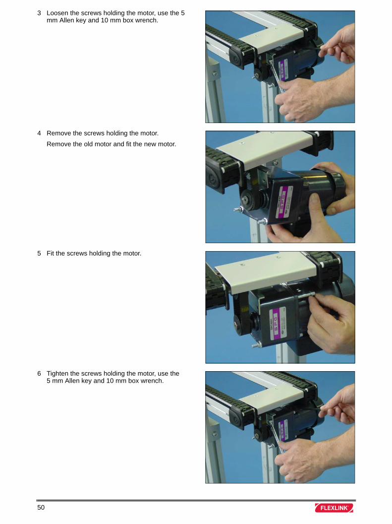
3 Loosen the screws holding the motor, use the 5 mm Allen key and 10 mm box wrench.
4 Remove the screws holding the motor.
Remove the old motor and fit the new motor.
5 Fit the screws holding the motor.
6 Tighten the screws holding the motor, use the 5 mm Allen key and 10 mm box wrench.
50
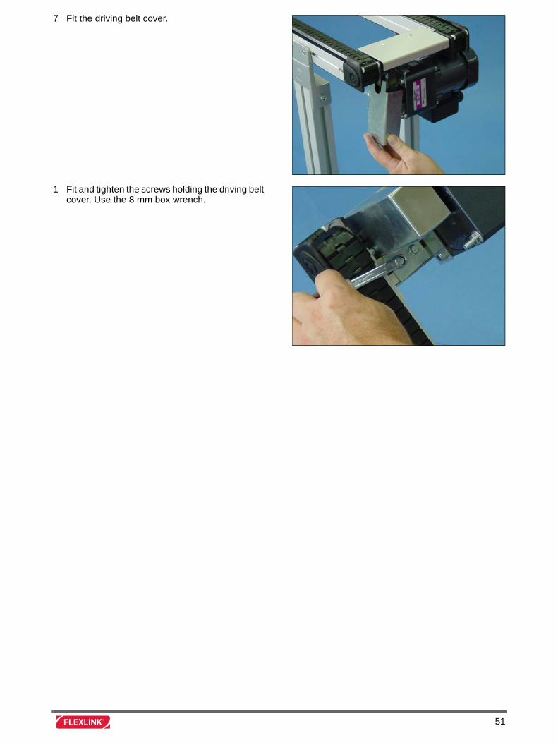
7 Fit the driving belt cover.
1 Fit and tighten the screws holding the driving belt cover. Use the 8 mm box wrench.
51

52
Replace motor on XT transfer unit XTPT M1
Introduction
Valid for XT transfer unit type M1.
Tools
Instruction
Phillips screwdriver
Allen key 5 mm
Box wrench 10 mm
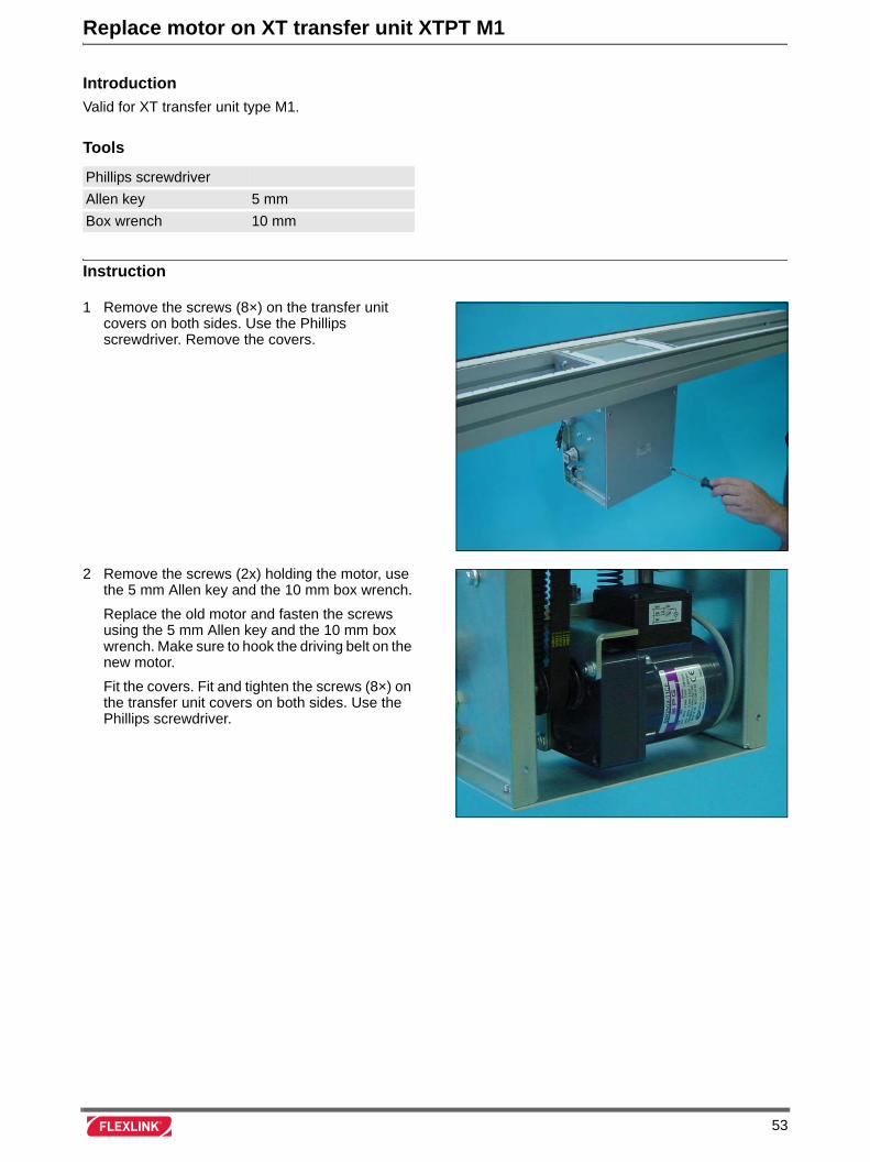
1 Remove the screws (8×) on the transfer unit covers on both sides. Use the Phillips screwdriver. Remove the covers.
2 Remove the screws (2x) holding the motor, use the 5 mm Allen key and the 10 mm box wrench.
Replace the old motor and fasten the screws using the 5 mm Allen key and the 10 mm box wrench. Make sure to hook the driving belt on the new motor.
Fit the covers. Fit and tighten the screws (8×) on the transfer unit covers on both sides. Use the Phillips screwdriver.
53

54
Replace motor on XT transfer unit XTPT M2
Introduction
Valid for XT transfer unit type M2.
Tools
Instruction
Allen key 3 mm
Allen key 5 mm
Box wrench 10 mm
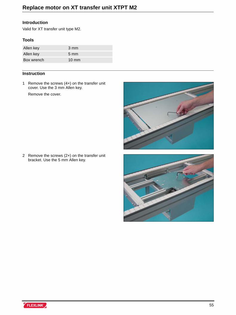
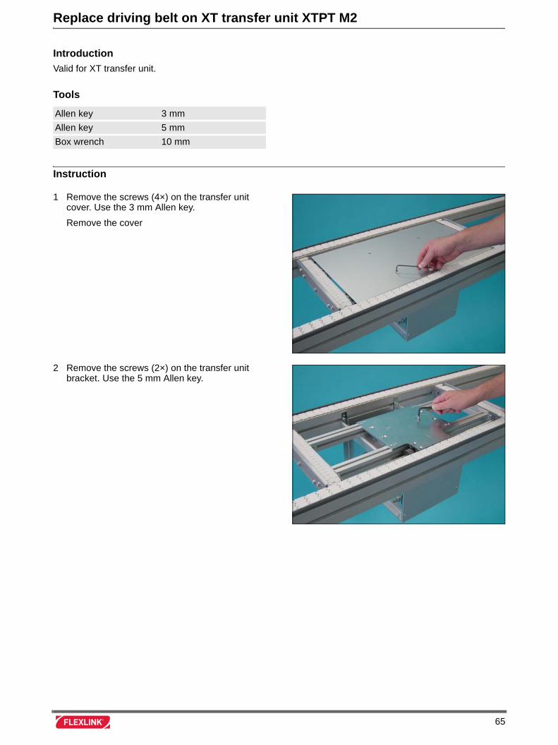
1 Remove the screws (4×) on the transfer unit cover. Use the 3 mm Allen key.
Remove the cover.
2 Remove the screws (2×) on the transfer unit bracket. Use the 5 mm Allen key.
55
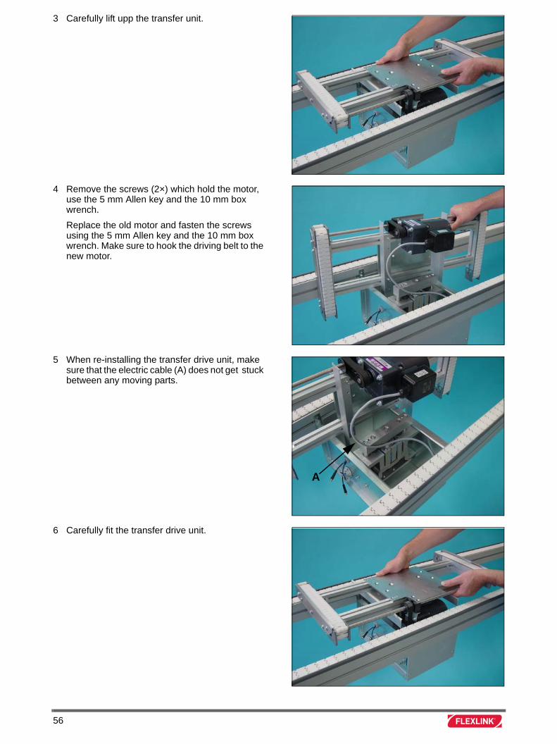
3 Carefully lift upp the transfer unit.
4 Remove the screws (2×) which hold the motor, use the 5 mm Allen key and the 10 mm box wrench.
Replace the old motor and fasten the screws using the 5 mm Allen key and the 10 mm box wrench. Make sure to hook the driving belt to the new motor.
5 When re-installing the transfer drive unit, make sure that the electric cable (A) does not get stuck between any moving parts.
6 Carefully fit the transfer drive unit.
A
56

7 Fit and tighten the screws (2×) on the transfer unit bracket. Use the 5 mm Allen key.
8 Fit the cover
Fit the screws (4×) holding the transfer unit cover. Use the 3 mm Allen key.
57

58
Replace driving belt on XT transfer unit XTPT M1
Introduction
Valid for XT transfer unit type M1.
Tools
Instruction
Phillips screwdriver
Allen key 3 mm
Allen key 5 mm
Box wrench 10 mm
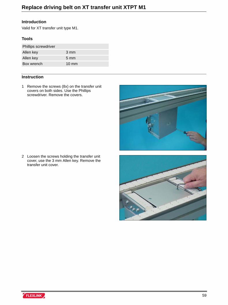
1 Remove the screws (8x) on the transfer unit covers on both sides. Use the Phillips screwdriver. Remove the covers.
2 Loosen the screws holding the transfer unit cover, use the 3 mm Allen key. Remove the transfer unit cover.
59
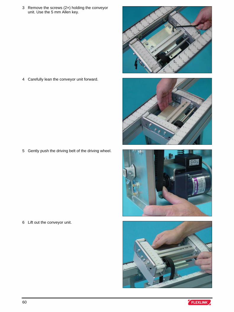
3 Remove the screws (2×) holding the conveyor unit. Use the 5 mm Allen key.
4 Carefully lean the conveyor unit forward.
5 Gently push the driving belt of the driving wheel.
6 Lift out the conveyor unit.
60
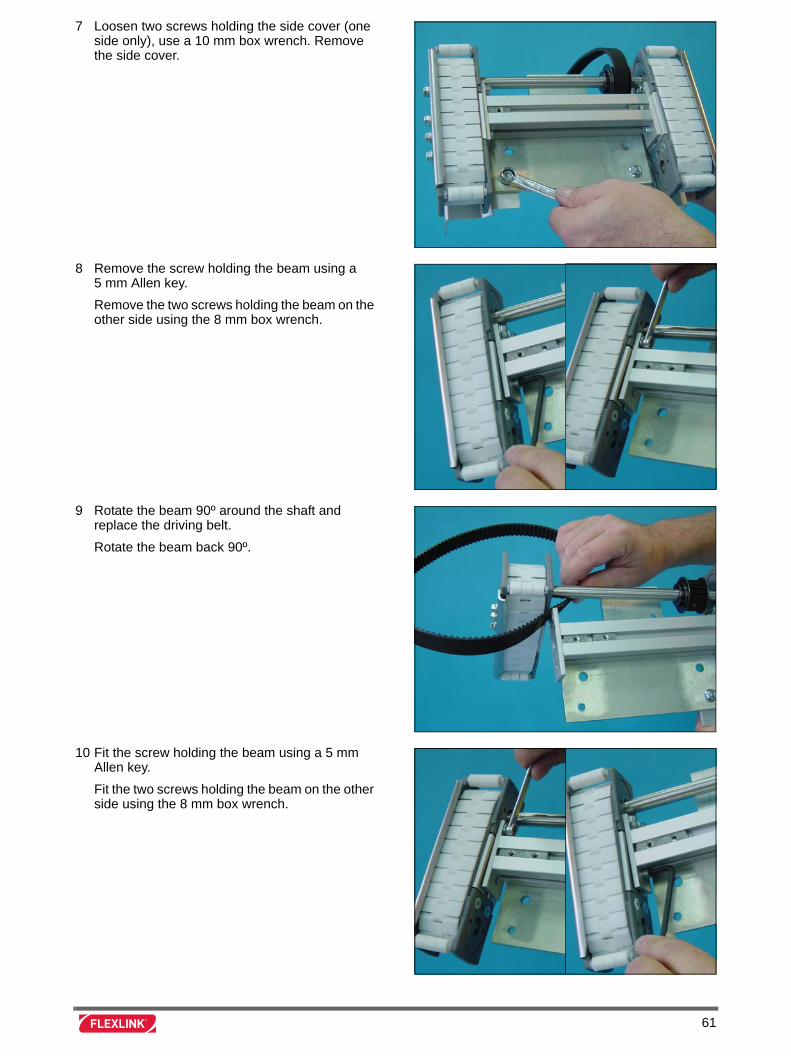
7 Loosen two screws holding the side cover (one side only), use a 10 mm box wrench. Remove the side cover.
8 Remove the screw holding the beam using a 5 mm Allen key.
Remove the two screws holding the beam on the other side using the 8 mm box wrench.
9 Rotate the beam 90º around the shaft and replace the driving belt.
Rotate the beam back 90º.
10 Fit the screw holding the beam using a 5 mm Allen key.
Fit the two screws holding the beam on the other side using the 8 mm box wrench.
61
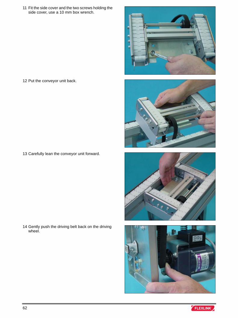
11 Fit the side cover and the two screws holding the side cover, use a 10 mm box wrench.
12 Put the conveyor unit back.
13 Carefully lean the conveyor unit forward.
14 Gently push the driving belt back on the driving wheel.
62
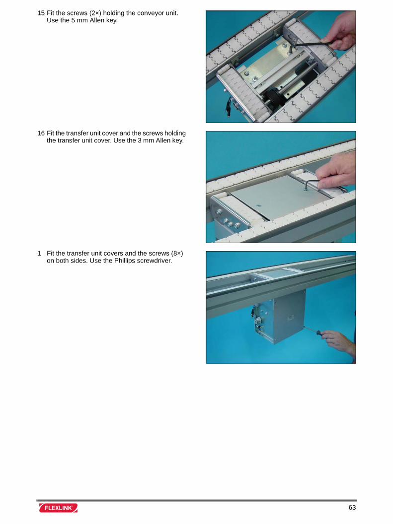
15 Fit the screws (2×) holding the conveyor unit. Use the 5 mm Allen key.
16 Fit the transfer unit cover and the screws holding the transfer unit cover. Use the 3 mm Allen key.
1 Fit the transfer unit covers and the screws (8×) on both sides. Use the Phillips screwdriver.
63

64
Replace driving belt on XT transfer unit XTPT M2
Introduction
Valid for XT transfer unit.
Tools
Instruction
Allen key 3 mm
Allen key 5 mm
Box wrench 10 mm
1 Remove the screws (4×) on the transfer unit cover. Use the 3 mm Allen key.
Remove the cover
2 Remove the screws (2×) on the transfer unit bracket. Use the 5 mm Allen key.
65
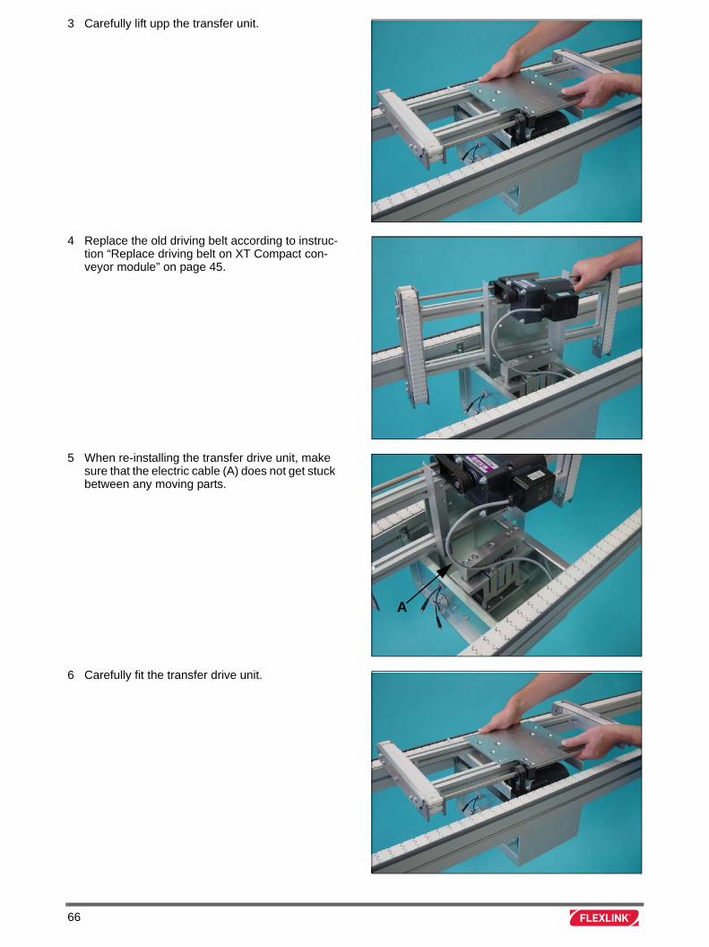
3 Carefully lift upp the transfer unit.
4 Replace the old driving belt according to instruc-tion “Replace driving belt on XT Compact con-veyor module” on page 45.
5 When re-installing the transfer drive unit, make sure that the electric cable (A) does not get stuck between any moving parts.
6 Carefully fit the transfer drive unit.
A
66
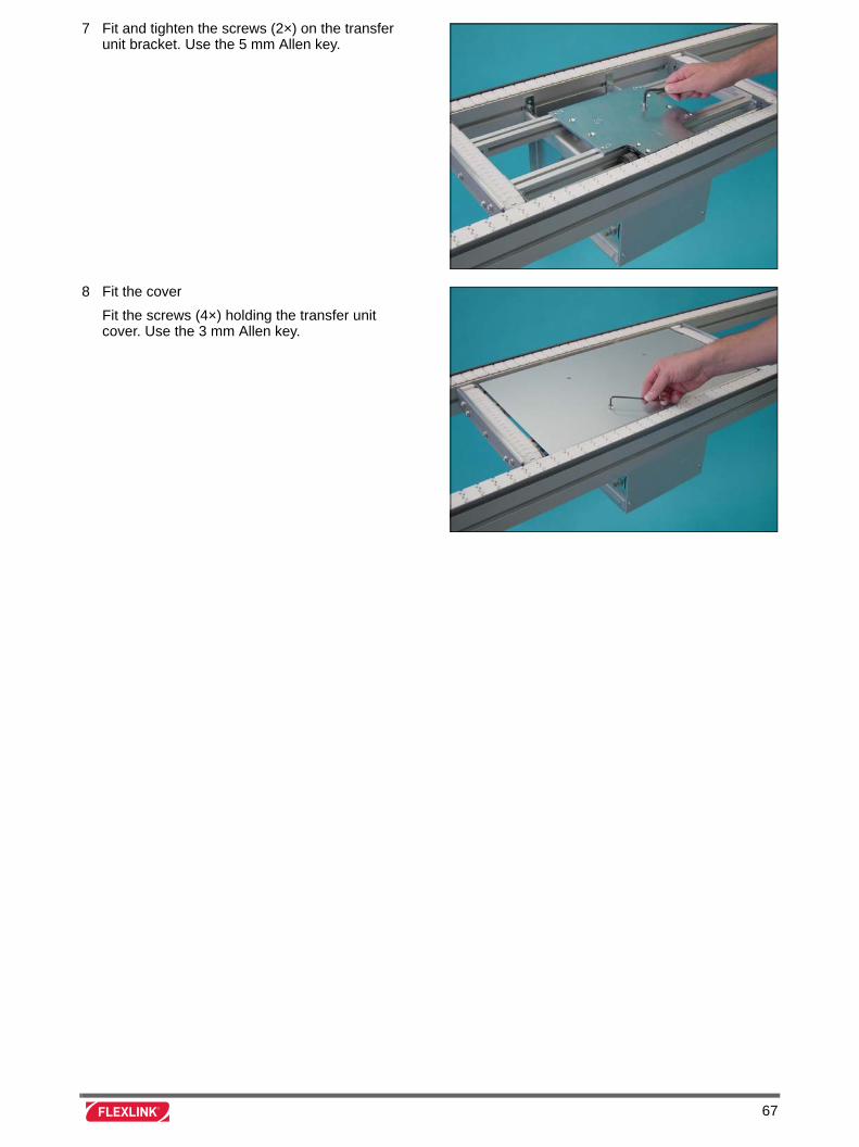
7 Fit and tighten the screws (2×) on the transfer unit bracket. Use the 5 mm Allen key.
8 Fit the cover
Fit the screws (4×) holding the transfer unit cover. Use the 3 mm Allen key.
67

68
Mounting guide pins to locating, lift-and-rotate and lift-and-locate station
Introduction
Valid for all locating stations.
Tools
Instruction
Allen key 4 mm
Soft faced hammer
Box wrench 10 mm
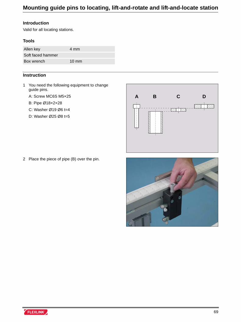
1 You need the following equipment to change guide pins.
A: Screw MC6S M5×25
B: Pipe Ø18×2×28
C: Washer Ø19 Ø6 t=4
D: Washer Ø25 Ø8 t=5
2 Place the piece of pipe (B) over the pin.
DCBA
69
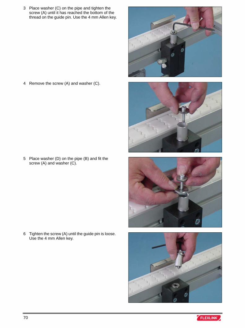
3 Place washer (C) on the pipe and tighten the screw (A) until it has reached the bottom of the thread on the guide pin. Use the 4 mm Allen key.
4 Remove the screw (A) and washer (C).
5 Place washer (D) on the pipe (B) and fit the screw (A) and washer (C).
6 Tighten the screw (A) until the guide pin is loose. Use the 4 mm Allen key.
70
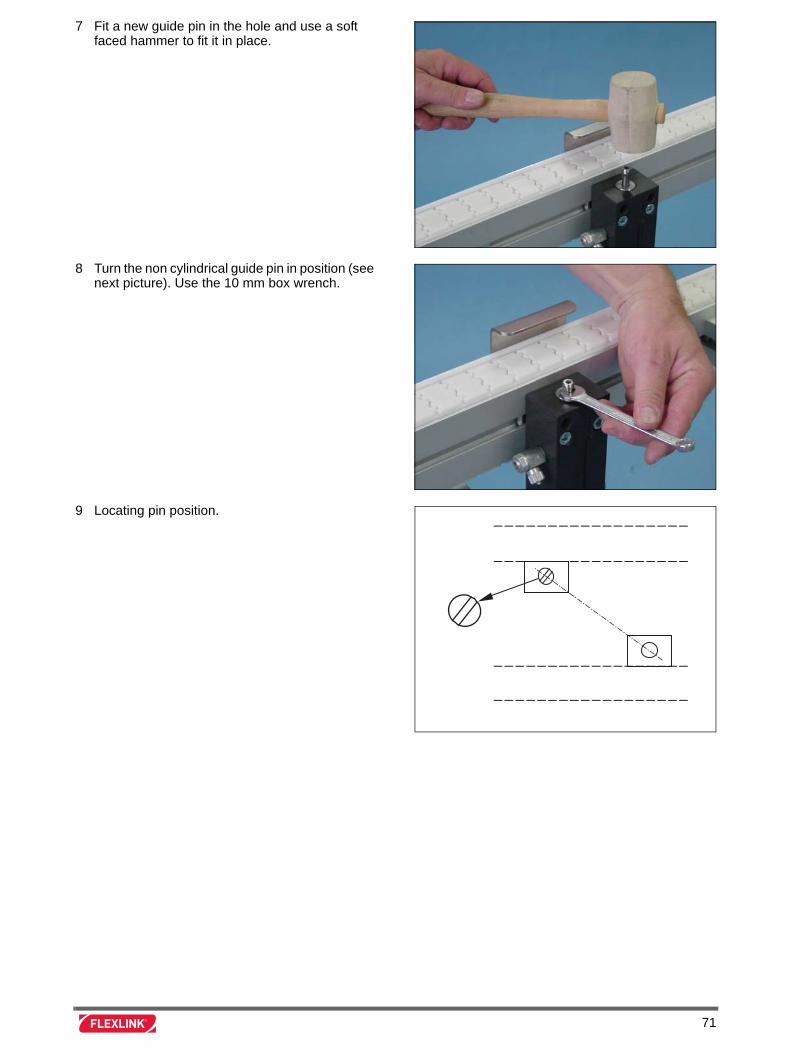
7 Fit a new guide pin in the hole and use a soft faced hammer to fit it in place.
8 Turn the non cylindrical guide pin in position (see next picture). Use the 10 mm box wrench.
9 Locating pin position.
71

72

Trouble shooting
73
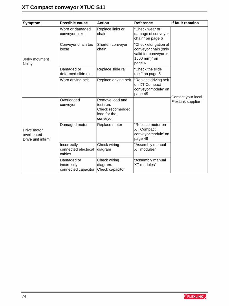
XT Compact conveyor XTUC S11
Symptom Possible cause Action Reference If fault remains
Jerky movmentNoisy
Worn or damaged conveyor links
Replace links or chain
“Check wear or damage of conveyor chain” on page 6
Contact your local FlexLink supplier
Conveyor chain too loose
Shorten conveyor chain
“Check elongation of conveyor chain (only valid for conveyor > 1500 mm)” on page 6
Damaged or deformed slide rail
Replace slide rail “Check the slide rails” on page 6
Worn driving belt Replace driving belt “Replace driving belt on XT Compact conveyor module” on page 45
Drive motor overheatedDrive unit infirm
Overloaded conveyor
Remove load and test run.Check recomended load for the conveyor.
Damaged motor Replace motor “Replace motor on XT Compact conveyor module” on page 49
Incorrectly connected electrical cables
Check wiring diagram
“Assembly manual XT modules”
Damaged or incorrectly connected capacitor
Check wiring diagram.Check capacitor
“Assembly manual XT modules”
74
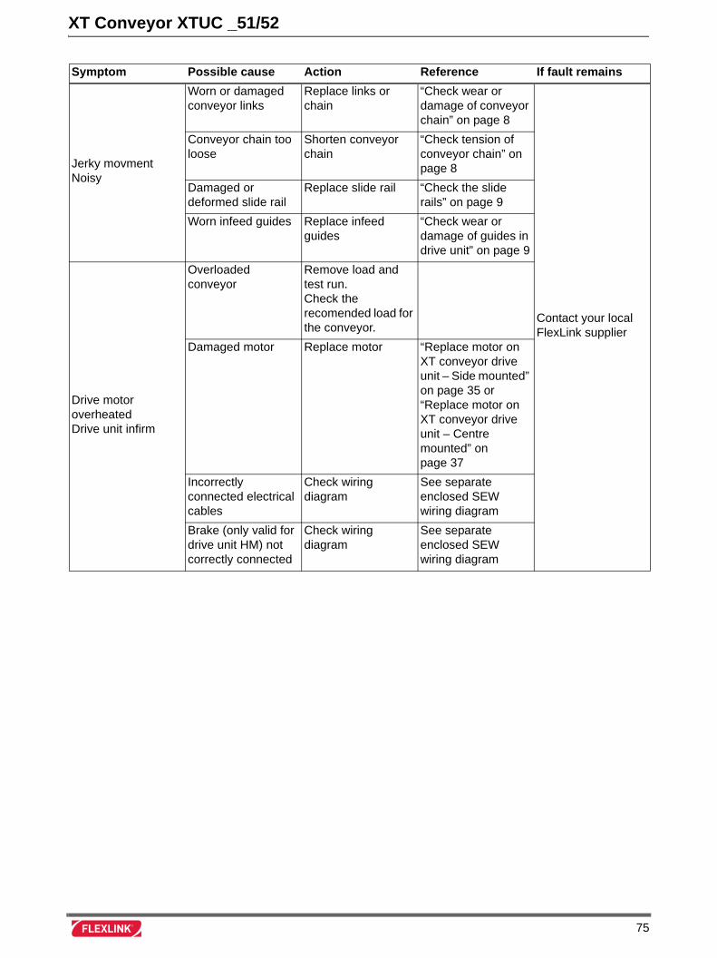
XT Conveyor XTUC _51/52
Symptom Possible cause Action Reference If fault remains
Jerky movmentNoisy
Worn or damaged conveyor links
Replace links or chain
“Check wear or damage of conveyor chain” on page 8
Contact your local FlexLink supplier
Conveyor chain too loose
Shorten conveyor chain
“Check tension of conveyor chain” on page 8
Damaged or deformed slide rail
Replace slide rail “Check the slide rails” on page 9
Worn infeed guides Replace infeed guides
“Check wear or damage of guides in drive unit” on page 9
Drive motor overheatedDrive unit infirm
Overloaded conveyor
Remove load and test run.Check the recomended load for the conveyor.
Damaged motor Replace motor “Replace motor on XT conveyor drive unit – Side mounted” on page 35 or “Replace motor on XT conveyor drive unit – Centre mounted” on page 37
Incorrectly connected electrical cables
Check wiring diagram
See separate enclosed SEW wiring diagram
Brake (only valid for drive unit HM) not correctly connected
Check wiring diagram
See separate enclosed SEW wiring diagram
75
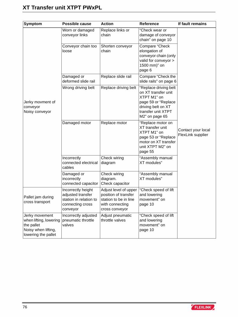
XT Transfer unit XTPT PWxPL
Symptom Possible cause Action Reference If fault remains
Jerky movment of conveyorNoisy conveyor
Worn or damaged conveyor links
Replace links or chain
“Check wear or damage of conveyor chain” on page 10
Contact your local FlexLink supplier
Conveyor chain too loose
Shorten conveyor chain
Compare “Check elongation of conveyor chain (only valid for conveyor > 1500 mm)” on page 6
Damaged or deformed slide rail
Replace slide rail Compare “Check the slide rails” on page 6
Wrong driving belt Replace driving belt “Replace driving belt on XT transfer unit XTPT M1” on page 59 or “Replace driving belt on XT transfer unit XTPT M2” on page 65
Damaged motor Replace motor “Replace motor on XT transfer unit XTPT M1” on page 53 or “Replace motor on XT transfer unit XTPT M2” on page 55
Incorrectly connected electrical cables
Check wiring diagram
“Assembly manual XT modules”
Damaged or incorrectly connected capacitor
Check wiring diagram.Check capacitor
“Assembly manual XT modules”
Pallet jam during cross transport
Incorrectly height adjusted transfer station in relation to connecting cross conveyor
Adjust level of upper position of transfer station to be in line with connecting cross conveyor
“Check speed of lift and lowering movement” on page 10
Jerky movement when lifting, lowering the palletNoisy when lifting, lowering the pallet
Incorrectly adjusted pneumatic throttle valves
Adjust pneumatic throttle valves
“Check speed of lift and lowering movement” on page 10
76
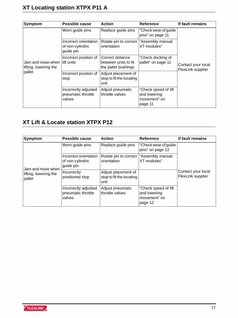
XT Locating station XTPX P11 A
XT Lift & Locate station XTPX P12
Symptom Possible cause Action Reference If fault remains
Jam and noise when lifting, lowering the pallet
Worn guide pins Replace guide pins “Check wear of guide pins” on page 11
Contact your local FlexLink supplier
Incorrect orientation of non-cylindric guide pin
Rotate pin to correct orientation
“Assembly manual XT modules”
Incorrect position of lift units
Correct distance between units to fit the pallet bushings
“Check docking of pallet” on page 11
Incorrect position of stop
Adjust placement of stop to fit the locating unit
Incorrectly adjusted pneumatic throttle valves
Adjust pneumatic throttle valves
“Check speed of lift and lowering movement” on page 11
Symptom Possible cause Action Reference If fault remains
Jam and noise when lifting, lowering the pallet
Worn guide pins Replace guide pins “Check wear of guide pins” on page 12
Contact your local FlexLink supplier
Incorrect orientation of non-cylindric guide pin
Rotate pin to correct orientation
“Assembly manual XT modules”
Incorrectly positioned stop
Adjust placement of stop to fit the locating unit
Incorrectly adjusted pneumatic throttle valves
Adjust pneumatic throttle valves
“Check speed of lift and lowering movement” on page 12
77
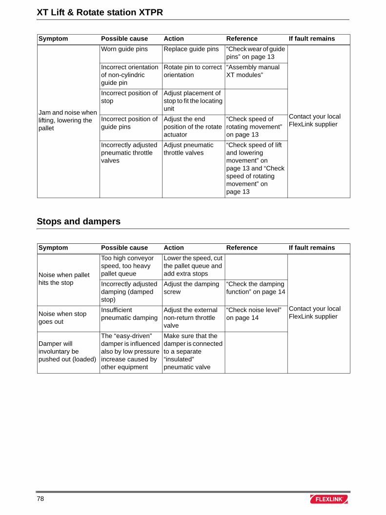
XT Lift & Rotate station XTPR
Stops and dampers
Symptom Possible cause Action Reference If fault remains
Jam and noise when lifting, lowering the pallet
Worn guide pins Replace guide pins “Check wear of guide pins” on page 13
Contact your local FlexLink supplier
Incorrect orientation of non-cylindric guide pin
Rotate pin to correct orientation
“Assembly manual XT modules”
Incorrect position of stop
Adjust placement of stop to fit the locating unit
Incorrect position of guide pins
Adjust the end position of the rotate actuator
“Check speed of rotating movement” on page 13
Incorrectly adjusted pneumatic throttle valves
Adjust pneumatic throttle valves
“Check speed of lift and lowering movement” on page 13 and “Check speed of rotating movement” on page 13
Symptom Possible cause Action Reference If fault remains
Noise when pallet hits the stop
Too high conveyor speed, too heavy pallet queue
Lower the speed, cut the pallet queue and add extra stops
Contact your local FlexLink supplier
Incorrectly adjusted damping (damped stop)
Adjust the damping screw
“Check the damping function” on page 14
Noise when stop goes out
Insufficient pneumatic damping
Adjust the external non-return throttle valve
“Check noise level” on page 14
Damper will involuntary be pushed out (loaded)
The “easy-driven” damper is influenced also by low pressure increase caused by other equipment
Make sure that the damper is connected to a separate “insulated” pneumatic valve
78
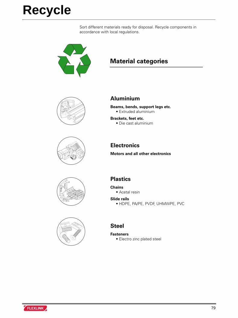
RecycleSort different materials ready for disposal. Recycle components inaccordance with local regulations.
Material categories
AluminiumBeams, bends, support legs etc. • Extruded aluminium
Brackets, feet etc. • Die cast aluminium
ElectronicsMotors and all other electronics
PlasticsChains • Acetal resin
Slide rails • HDPE, PA/PE, PVDF, UHMWPE, PVC
SteelFasteners • Electro zinc plated steel
79