MAINTENANCE MANUAL - RepairDynamicsrepairdynamics.com/Kipor-Diesel-Gen-ServiceManual.pdf ·...
44
DIESEL GENERATOR SINGLE-PHASE: KDE2200X/E KDE3500X/E/T KDE5000X/E/T KDE6500X/E/T/TA KDE6700T/TA KDA6700TA/TAO THREE-PHASE: KDE6500X3/E3/T3 KDE6700T3/TA3 KDA6700TA3/TAO3 MAINTENANCE MANUAL
Transcript of MAINTENANCE MANUAL - RepairDynamicsrepairdynamics.com/Kipor-Diesel-Gen-ServiceManual.pdf ·...

DIESEL GENERATOR
S I N G L E - P H A S E : K D E 2 2 0 0 X / E K D E 3 5 0 0 X / E / T K D E 5 0 0 0 X / E / T K D E 6 5 0 0 X / E / T / TA K D E 67 0 0 T / TA K D A 67 0 0 TA / TA OT H R E E - P H A S E : K D E 6 5 0 0 X 3 / E 3 / T 3 K D E 67 0 0 T 3 / TA 3 K D A 67 0 0 TA 3 / TA O 3
MAINTENANCE MANUAL

PREFACE
WARNING
Please read this instruction and ensure understand all regulations concerning
handling, check and maintenance thoroughly prior to application.
Failure to follow this instruction may cause serious accidents.
Incorrect operation is likely to lead accidents.
Operate and maintain the machine on the basis of thorough understanding of this
instruction.
Place this instruction in the fitting box or near machine after reading because it
is regularly needed.
If this introduction is lost or damaged, please order one from local KIPOR
dealer.
Please provide this introduction to another user whom machine will be
transferred to.
Machine may be improved or modified. Therefore actual conditions may be
different from this introduction.
If you have any doubt, please consult local KIPOR dealer.
Machine is the special diesel generator for ground application.
Safety information contained in this introduction are extremely important.
Please read and understand it.

Content
1.Technical Specifications
1.1Main Technical Parameters
1.2Power vs Voltage Diagram of Generating Set Output Characteristic
1.3Overall Dimension Drawing
1.4Electric Principle and Wiring Diagram for Various Models of Generating Set
2.Important Information
2.1Versions Description
2.2Safety
2.3Importance of Proper Maintenance
2.4Important Safety Precautions
2.5Maintenance Regulations
2.6Electric Precautions
2.7Parts Name
2.8Location of Generating Set Series Number
2.9Maintenance Norm for Generating Set
2.10 Torque List (Torque Value)
2.11 Factory Settings of Generating Set
2.12 Troubleshooting Open-shelf Diesel Engine and Quiet Generating Set
2.12.1General Symptom and Possible Cause
2.12.2Flow Chart of Troubleshooting
3.Maintenance Checks
3.1Service List
3.2Checks
3.2.1Check Fuel Oil
3.2.2Check Engine Oil
3.2.3Check Air Cleaner
3.2.4Check Starting Performance of Generating Set
3.2.4.1Recoil Starting
3.2.4.2Electric Starting
3.2.5Check Battery
3.2.6Checks during the Running

3.2.6.1 Check A.C.Output Characteristic
3.2.6.2 Check D.C
3.2.7 Check Overload Operation
3.2.8 Check Stopping of Generating Set
4.Maintenance
4.1Oil-line and intake/exhaust parts
4.1.1Engine Oil
4.1.2Replace Engine Oil
4.1.3Oil Tank / Fuel Oil Filter
4.1.4Oil Pipe / Oil Pump
4.1.5Air Cleaner
4.1.6Muffler
4.2Control Panel
4.2.1A.C. Receptacle
4.2.2D.C. Receptacle or Terminal Post
4.2.3Starting Switch
4.2.4Voltmeter
4.2.5Air Breaker
4.2.6Engine Oil Alerting Apparatus
4.3Generator
4.3.1Generator
4.3.2Installation of Rotor
4.3.3Stator
4.4Cabinet
4.4.1Right Plate
4.4.2Left Plate
4.4.3Cabinet
4.4.4Cabinet Transformer
4.4.5Chassis
5.Service of Intelligent Control Panel for KDE6700TA/TA3
5.1Setting
5.2Check
5.3Maintenance
5.4Parameter Setting List
5.5Diagram of Switch Position for Address Setting

1. SPECIFICATIONS
1-1 Main technical Specifications
Mo
de
lK
DE
35
00
XK
DE
35
00
EK
DE
65
00
XK
DE
65
00
EK
DE
35
00
T
KD
E3
70
0T
KD
E2
20
0X
KD
E2
20
0E
Generating Set
Ra
ted
fre
qu
en
cy (
Hz)
Rat
ed o
utpu
t pow
er (k
VA)
Max
. pow
er (
kW)
Rat
ed c
urre
nt (
A)
Rat
ed ro
tatio
n sp
eed
(r/m
in )
Ph
ase
Po
we
r fa
cto
r (c
os
)
Exc
itatio
n typ
e
DC
ou
tpu
t
Ge
ne
rato
r st
ruct
ure
Ge
ne
rato
r
Insu
latio
n g
rad
e
Po
le n
um
be
r
50
50
50
50
60
60
60
3.2
3.8
55
.53.
23
.8
23
0
30
00
24
0/1
20
36
00
30
00
36
00
36
00
36
00
30
00
30
00
23
02
30
230
240/
120
240/
120
240/
120
Sin
gle
ph
ase
Se
lf-e
xcita
tion
12
V/8
.3A6
05
06
0
1.7 2
23
0
30
00
2.2
240/
120
36
00
Sin
gle
ph
ase
3.2
3.8
Rat
ed v
olta
ge (
V)
7.4
12
.213
.8/2
7.5
19
.620
.8/4
1.7
12
.213
.8/2
7.5
8.3/
16.7
12
.213
.8/2
7.5
2.8
4.5
2.8
2.8
3.3
3.3
3.3
52
Sin
gle
ph
ase
Sin
gle
ph
ase
Sin
gle
ph
ase
11
11
1
On
e b
ea
rin
g, S
elf
ven
tila
tion
Ro
tatio
n m
ag
ne
tic fie
ld, ro
tor
chu
te
BB
BB
22
22
2
KM
17
0F
KM
17
8F
KM
18
6F
KM
17
8F
KM
17
8F
On
e c
ylin
de
r, 4
ch
oke
, a
ir c
oo
led
, in
line
d, d
iese
l en
gin
e
En
gin
e m
od
el
En
gin
e typ
e
Bo
re
ch
oke
(m
m)
70
55
78
62
86
72
78
62
78
62

Mo
de
lK
DE
35
00
XK
DE
35
00
EK
DE
65
00
XK
DE
65
00
EK
DE
35
00
T
KD
E3
70
0T
KD
E2
20
0X
KD
E2
20
0E
Str
uct
ure
typ
e
Engine
Dis
pla
cem
en
t(L
)
Co
mp
ress
ion
ra
te
Rat
ed p
ower
kW
/(r/
min
)
Fu
el m
od
el
Lu
brica
ting
oil
mo
de
l
Volta
ge d
eviat
ion a
t ste
ady s
tate
Fre
nq
ue
ncy
ra
te
Volta
ge wa
ve ty
pe di
stortio
n rate
(zero
load)
Insula
tion r
esist
ence
(at c
old st
ation
)
Fuel
con
sum
ptio
n ra
te(g
/kw.
h)
Cap
abili
ty o
f fue
l tan
k(L)
Con
tinuo
us ru
nnin
g tim
e(H
r)
Over
all d
imen
sion(
mm
) (L
WH)
Ne
t w
eig
ht (k
g)
Sta
rtin
g typ
e
Noise
leve
l(dBA
/7m
)(at r
ated
load
)
0.2
11
20
:01
2.5
/30
00
2.8
/36
00
0.2
96
20
:01
0.4
18
19
:1
0.2
96
20
:01
0.2
96
20
:01
3.7
/30
00
4.0
/36
00
5.7
/30
00
6.3
/36
00
3.7
/30
00
4.0
/36
00
3.7
/30
00
4.0
/36
00
37
0
15
22
64
04
80
53
0
X:5
3 E
:60
77
Op
en
fra
me
o#
(su
mm
er)
, -1
0#
(w
inte
r),-
35
# (
ch
ill c
old
) d
iese
l
SA
E1
0W
30
(ab
ove
CC
gra
de
)
2.5
%
5%
Sin
gle
ph
ase
5
% T
hre
e-p
ha
se
8
%
2M
X:R
ecoi
l sta
rter;
E:R
ecoi
l sta
rter/E
lect
ric s
tarte
r
37
0
15
14
64
04
80
53
0
70
77
Op
en
fra
me
36
0
15 8
72
04
92
65
0
X:9
5 E
:10
0
79
Op
en
fra
me
37
0
16
14
.5
83
05
32
74
0
14
0
70
Sile
nt
37
0
16
14
.5
84
55
47
74
2
15
0
79
Sile
nt
Re
co
il s
tart
er
/Ele
ctr
ic s
tart
er
X:R
ecoi
l sta
rter;
E:R
ecoi
l sta
rter/E
lect
ric s
tarte
rE
lectr
ic s
tart
er
Ele
ctr
ic s
tart
er
Generating set
Mo
de
lK
DE
67
00
T/T
A/T
AO
KD
E6
50
0X
3/E
3/T
3K
DE
6700
T3/T
A3/
TAO
3
KD
E6
50
0T
Generating Set
Ra
ted
fre
qu
en
cy (
Hz)
Ra
ted
ou
tpu
t p
ow
er
(kV
A)
Ma
x. p
ow
er
(kW
)
Ra
ted
cu
rre
nt ( A
)
Ra
ted
ro
tatio
n s
pe
ed
(r/
min
)
Ph
ase
Po
we
r fa
cto
r (c
os
)
Excita
tio
n typ
e
DC
ou
tpu
t
Ge
ne
rato
r str
uctu
re
Ge
ne
rato
r
Insu
latio
n g
rad
e
Po
le n
um
be
r
Sin
gle
ph
ase Se
lf-e
xcita
tio
n
12
V/8
.3A
Ra
ted
vo
ltag
e (
V)
Sin
gle
ph
ase
11
On
e b
ea
rin
g, S
elf v
en
tila
tio
n
Ro
tatio
n m
ag
ne
tic fie
ld, ro
tor
ch
ute
BB
B
22
22
KM
18
6F
KM
18
6F
KM
18
6F
KM
18
6F
On
e c
ylin
de
r, 4
ch
oke
, a
ir c
oo
led
, in
line
d, d
iese
l e
ng
ine
En
gin
e m
od
el
En
gin
e typ
e
Bo
rech
oke
(m
m)
86
72
86
72
86
72
86
72
50
50
50
60
60
6kV
A7
kV
A
23
0
30
00
24
0/1
20
36
00
30
00
36
00
36
00
30
00
40
0/2
30
40
0/2
30
41
6/2
40
41
6/2
40
60
50
60
4.5 5
23
0
30
00
5.5
24
0/1
20
36
00
Th
ree
ph
ase
19
.61
9.6
7.9
20.8
/41.
77
.9
5.5
kV
A6
.3kV
A5
Th
ree
ph
ase
0.8
(la
g)
0.8
(la
g)
20.8
/41.
7
4.5 5
5.55
6kV
A7
kV
A
5.5
kV
A6
.3kV
A
8.7
8.7
No
12
VN
o 1
2V
B

Note: Explaination for generating set model: KDE is the generating set, 2200 is the set
model. Function code: X is recoil starter E is electric starter set, T is electric starter
silent set, A is digital control panel set, O is automatic starter and automatic change
function with ATS. A, O code only used for above 6700 set model.
Str
uctu
re typ
e
Engine
Dis
pla
ce
me
nt(
L)
Co
mp
ressio
n r
ate
Ra
ted
po
we
r kW
/(r/
min
)
Fu
el m
od
el
Lu
brica
tin
g o
il m
od
el
Volta
ge d
evia
tion
at s
tead
y st
ate
Fre
nq
ue
ncy r
ate
Volta
ge w
ave t
ype d
istor
tion r
ate(ze
ro lo
ad)
Insu
latio
n re
siste
nce(
at c
old
stat
ion)
Fue
l con
sum
ptio
n ra
te(g
/kw
.h)
Ca
pa
bili
ty o
f fu
el ta
nk(L
)
Con
tinuo
us r
unni
ng ti
me(
Hr)
Ove
rall
dim
ensi
on(m
m) (
LW
H)
Ne
t w
eig
ht (k
g)
Sta
rtin
g typ
e
Noi
se le
vel(d
BA/7
m)(a
t rat
ed lo
ad)
0.2
11
20
:01
5.7
/30
00
6.3
/36
00
0.2
96
20
:01
0.4
18
19
:1
0.2
96
20
:01
5.7
/30
00
6.3
/36
00
5.7
/30
00
6.3
/36
00
5.7
/30
00
6.3
/36
00
36
0
15 8
91
05
30
74
0
16
5
70
Sile
nt
o#
(su
mm
er)
, -1
0#
(w
inte
r),-
35
# (
ch
ill co
ld)
die
se
l
SA
E1
0W
30
(ab
ove
CC
gra
de
)
2.5
%
5%
Sin
gle
ph
ase
5
% T
hre
e-p
ha
se
8
%
2M
37
0
15
14
91
55
47
74
2
17
7
70
Sile
nt
36
0
15 8
91
05
30
74
0
16
5
70
Sile
nt
37
0
16
14
.5
91
55
47
74
2
17
7
70
Sile
nt
Ele
ctr
ic s
tart
er
Generating set
Mo
de
lK
DE
67
00
T/T
A/T
AO
KD
E6
50
0X
3/E
3/T
3K
DE
6700
T3/
TA3/
TAO
3
KD
E6
50
0T
Ele
ctr
ic s
tart
er
Ele
ctr
ic s
tart
er
Ele
ctr
ic s
tart
er
Main technical specification of single-phase and three-phase generator sets
Model
Rated frenquency (Hz)
Rated output(kW)
Rated output (V)
Rated current(A)
Phase
Poweer factor (cos )
Rated welding current(A)
Welding work voltage(V)
We
ldin
g w
ork
con
diti
on
(D
C)
We
ldin
g a
nd
ge
ne
ratin
g s
et
Ge
ne
ratin
g w
ork
co
nd
itio
n (
AC
)
Welding voltage at zero load(V)
Welding continous load rate(%)
Diameter of welding rod (mm)
Adjusting range of welding current (A)
50
2.8
230
12.2
60
3
240
12.5
50
2.8
230
12.2
60
3
240
12.5
Single
1
70-75
160
25-35
60%
30-180
1.6-4.0
Single
1
60-65
160
26
60%
50-180
1.6-4.0
KDE6500XW/EW KDE6700TW
Rated rotation speed r/min
Exciation type
Rectify type
Connecting type
Insulation grade
Voltage deviation at steady state
Frenquency rate
Motor
Pole number
Engine model
Engine type
Displacement(ml)
Bore x stroke(mm)
Compression rate
Rated power Kw/(r/min)
Fuel model
Lubricating oil model
Fuel consumption(g/kw.h)
Oil tank capacity (L)
Continuous running time(h)
Overall dimension(L W H)[mm(in)]
Net weight[kg(1bs)]
Starting type
Noise level [db(A)@7m](at rated load)
Structure
X XE
ng
ine
Set
Voltage wave type distortion rate(zero load)
3000 36000 3000 36000
Self exciation and automatic voltage adjusting(AVR)
IGBT+three-phase rectify bridge(PWM ) IGBT+three-phase rectify bridge(PWM)
Single bearing
2.5%
5%
5%
Rotor chute band damping winding
2
KM186FAG
418
86X72
19
5.7/3000 6.3/3600
2
KM186FAG
418
86X72
19
5.7/3000 6.3/3600
Inlined .single .4-stroke.air cooled Inlined .single .4-stroke.air cooled
SAE10W30 (above CC grade)
360
15
6.5
840x535x650
X 115 E 120
360
16
T:7
915x547x742
188
75
EW/XW Open-frame TW Silent
0#(Summer) -10#(Winter) -35#(Chill cold)Light diesel
XW: Recoil starter EW/TW: Electric starter
70
B B

1-2 The set power and voltage characteristic curves
The following curves indicate generator performance at average conditions. The
performance may vary according to ambient temperature.
Before generator set leave the factory, voltage is set beyond rated voltage. When
generator set start running, output voltage should be equal to rated output, as
load time increase, rated voltage decrease.
(1) AC external characteristic curves of KDE2200X/E generator sets
(2)AC external characteristic curves of KDE3500X/E generator sets
ACouput
voltage
V
130
120
110
1000 2 4 6 8 10 12 14 16 18 20
KDE2200X/E 120V
250
240
230
2200 2 4 6 8 10
KDE2200X/E 240V
0 2 4 6 8 10
KDE2200X/E
18
16
14
12
10
0 2 4 6 8 10 12 14 16 18 20 22 24 26 28 30
KDE3500X/E 120V
130
120
110
100
KDE3500X/E 240V
0 2 4 6 8 10 12 14 16 18
250
240
230
220
KDE3500X/E
18
16
14
12
10
0 2 4 6 8 10
130
120
110
100
KDE6500X/E 120V
0 2 4 6 8 10 12 14 16 18 20 22 24 26 28 30 32 34 36 38 40 42
250
240
230
2200 2 4 6 8 10 12 14 16 18 20 22
KDE6500X/E 240V KDE6500X/E
0 2 4 6 8 10
18
16
14
12
10
0 2 4 6 8 10 12 14 16 18 20 22 24 26 28 30 32 34 36 38 40 42
KDE6500X/E 120V
130
120
110
100
250
240
230
220
18
16
14
12
10
(3)AC external characteristic curves of KDE6500X/E generator sets
(4)AC external characteristic curves of KDE6500T generator sets
0 2 4 6 8 10 12 14 16 18 20 22
KDE6500X/E 240V KDE6500X/E
0 2 4 6 8 10

(5)AC external characteristic curves of KDE6700T/TA generator sets
(6)AC external characteristic curves of KDE6700T3/TA3 generator sets
(7)AC external characteristic curves of KDE6500EW/XW generator sets
130
120
110
100
KDE6700T/TA 120V
0 2 4 6 8 10 12 14 16 18 20 22 24 26 28 30 32 34 36 38 40 42
250
240
230
220
0 2 4 6 8 10 12 14 16 18 20 22
KDE6700T/TA 240V KDE6700T/TA
0 2 4 6 8 10
18
16
14
12
10
KDE6500EW/XW
75
70
65
60
55
50
45
40
35
30
25 18
0
16
0
12
0
10
0
80
60
40
432
416
400
KDE6700T3/TA3 416V/240V KDE6700T3/TA3
250
240
220
0 2 4 6 8
250
240
230
220
0 2 4 6 8
0 2 4 6 8 10 12
0
KDE6500EW/XW
1-3 Overall dimension drawing Unit mm KDE2200X/E generator sets
KDE3500X/E generator sets

KDE6500X/E/X3/E3 generator sets
KDE6500T/T3 generator sets
KDE6700T/TA/T3/TA3 generator sets
KDE6500XW/EW generator sets
930

KDE3500X/E&KDE6500X/E generator sets
KDE3500X KDE6500X Single voltage output, electric schematic diagram the same
(Yellow)
(Black)
Voil pressure indicator light
Voil pressure protection
Sto
p e
lect
rom
ag
ne
t
Charging winding
Main winding Main winding
Sampling winding
Exc
ita
tion
win
din
g
Assis
tant
exc
itatio
n wi
ndin
g
Air switch
Voltmeter Over loading protection
Double voltagesimultaneousant put
current mutual-
inducator
1-4 Wiring diagrams of:
KDE2200X/E generator sets
KDE2200X single voltage output, electric schematic diagram
Low oil pressureprotection
Low oil pressureindicator light
Charging winding
Air switch Single voltoge output
Exc
itatio
n w
indi
ng
Ass
ista
nt e
xcita
tion
w
ind
ing
Main winding Main winding
Sto
p e
lecto
ma
gn
et
Voltmeter
Sampling winding
KDE2200X Double voltage selective output, electric schematic diagram
Low oil pressureprotection
Low oil pressureindicator light
Sto
p e
lect
om
ag
ne
t
Charging winding Sampling winding
Main winding Main winding
Excit
atio
n wi
ndin
g
Assis
tant e
xcita
tio
n
win
din
g
Breaker
Output
Output
Voltmeter indicates 240V & 20V respectively
Voltmeter indicates 120V output
Low oil pressureprotection
Low oil pressureindicator light
Sto
p e
lecto
ma
gn
et
Charging windingSampling winding
Main winding Main winding
Excit
atio
n wi
ndin
g
Assis
tan
t e
xcita
tio
n
win
din
g
Air switch
KDE2200X Double voltage simultaneous output, electric schematic diagram
Output
Air switch
Air switch
Output
Output

KDE3500X KDE6500X
Double voltage selective output electric schematic diagram the same
Lo
w o
il p
ressu
re
dic
ato
r lig
ht
Lo
w o
il p
ress
ure
pro
tectio
n
Sto
p e
lectro
ma
ge
nt
A
ssis
tan
t e
xcita
tio
n
win
din
g
Exc
itatio
n w
indi
ng
Main winding Main winding
Charging winding Sampling winding
Current mutual-inducator
Voltmeter indicates
Excitation
winding
Breaker
Output
Output
Protect
Overloading
KDE3500X KDE6500X
Double voltage simultaneous output, electric schematic diagram
Vo
il p
ressu
re in
dic
ato
r lig
ht
Vo
il p
ress
ure
p
rote
ctio
n
Stop
ele
ctro
mag
net
Charging winding
Main winding Main winding
Sampling winding
Exci
tatio
n w
indi
ng
Assis
tant
exc
itatio
n wi
nding
Air switch
Over loading protection
Current mutual-inducator
Air switch
Air switch
Output
Output
Voltmeter mdicates
KDE3500E KDE6500E Single roltage output, electric schematic diagram the same
Red
Sampling winding Black
Yellow & Green
Green
White
Green
Ch
arg
ing
re
gu
lato
r
Yellow
Start relay
Start electric motor
White
Yellow & Green
Blue
Blue
Red
Yellow Black
Black
Protection
Low oilpressure switch
BL
KDE3500E KDE6500E Double voltage selective output, electric schematic diagram the same
Red
Sampling winding
Yellow&Green
Ch
arg
ing
re
gu
lato
r
Start relay
Start electric motor
White
Black
Protection
Low oil pressure switch
RedBrown
Blue
Voltmeter indicates 240V & 20V respectively
Output
Output
Black
BlackBlue
Blue
Yellow Red
Yellow
White
Yellow & Green
Breaker
Green
Green

Protection
Low oil pressure switch
Output
Output
Voltmeter indicates
Air switch
Air switch
Air switch
Black
Black
Start relay
Start electric motor
Blue
Blue
Yellow
Red
White
Yellow & Green
Red
Sampling winding
Black
Brown
Blue
Green
White
Ch
arg
ing
reg
ula
tor
Yellow & Green
KDE3500E KDE6500E Double voltage simultaneous output, electric schematic diagram the same
KDE3500T&KDE6500T generator sets
KDE3500T KDE6500T Single voltage output, electric schematic diagram
Red
Electric switch lock
Start electromagnet
Sto
rag
e b
atte
ry
Throttle electromagnetic valve S
tart
e
lect
ricm
oto
r
Voil
pres
sure
pro
tect
ion
Flywheel generator
Rregulator
Voil pressure indicator light
Black
Yellow
Main winding Main winding
Sampling winding
Exci
tatio
n w
indi
ng
Assis
tant
exc
itatio
n wi
nding
Ele
ctric
switc
h lo
ck
Start
ele
ctrom
agne
t
Stor
age
batte
ry
Thro
ttle
elec
trom
agne
tic
valve
Start electric-motor
Fly
wh
ee
l ge
ne
rato
r
reg
ula
tor
Sam
plin
gw
indi
ng
Bro
wn
Bla
ck
Re
d
Blu
e
Vo
ltm
ete
r m
dic
ate
s 2
40
V &
20
V
Ou
tpu
t Ou
tpu
t
Voil pressure indicator light
Re
d
Bre
ake
r
Ye
llow
& G
ree
n
Voil pressure protection
KD
E3
50
0T
KD
E6
50
0T
Do
ub
le v
olta
ge
se
lect
ive
ou
tpu
t, e
lect
ric
sch
em
atic
dia
gra
m
Ele
ctric s
witc
h lo
ck
Sto
rage
ba
ttery
Start electricmotor
Fly
wh
ee
lg
en
era
tor
reg
ula
tor
Sa
mp
ling
win
din
g
Bro
wn
Air s
witc
h
Vo
ltme
ter
md
ica
tes
Air s
witch
Air s
witch
Ou
tpu
t Ou
tpu
t
Ye
llow
& G
ree
n
Voil pressure indicator light
Vo
ilp
ressu
re
pro
tect
ion
Bla
ck
Re
d
Blu
eSt
art
electr
omag
net
KD
E6
50
0T
K
DE
35
00
T D
ou
ble
vo
ltag
e s
imu
ltan
eo
us
ou
tpu
t, e
letr
ic s
che
ma
tic d
iag
ram

KDE6700TA generator sets
KDE6700TA Single voltage output, electric schematic diagram
Ass
ista
nt e
xcita
tion
win
din
g
Exc
ita
tion
win
din
g
Current mutual-inducator
Sampling winding
Main
wind
ing
Th
rottle
e
lect
rom
ag
ne
tice
va
lve
Flyw
heel
gene
rato
r
Regu
lator
Storage battery
Yellow&Green
Red Bla ck
Red
Current sampling
Starting electromagnet
Starting electric motor
Blue
Inte
llig
ne
t b
oa
rd c
on
rolle
r
Ch
arg
ing
win
din
g
Blue
Blue
Fuse
OFF-ON relationship list of electic switch lock
Red
Black
Direct current socket
RedBlack
Voltage sampling converter
GreyGrey
White
White
Yellow
Yellow Green
Orange Flyw
heel
AC
Brown Purple
Protect
Red
Blue
Red
Fuse
White Fuse
Simple intellagent screen
BreakerRed
Black
Voltage sampling
Volta
ge sa
mplin
g
Green
KDE6700TA Doulbe voltage selective output electric schematic diagram
Current mutual-inducator
Sampling winding
Main
wind
ing
Assista
nt e
xcitatio
n
win
din
g
Excita
tion
win
din
g
Th
rottle
e
lect
rom
ag
ne
tice
va
lve
Flyw
heel
gene
rato
r
Regu
lator St
orag
e batt
ery
RedBlack
Current sampling
Starting electromagnet
Starting electric motor
Blue
Inte
llig
ne
t b
oa
rd c
on
rolle
r
Ch
arg
ing
win
din
g
Blue
Blue
Fuse
OFF-ON relationship list of electic switch lock
Red
Black
direct current socket
BlackRed
Breaker
BlueRedBlack
RedBlack
Voltage sampling converter
GreyGreyGreyGrey
Green
White
White
Yellow
Yellow Green
OrangeFlywheel AC
Brown Purple
Protect
Red
Blue
Red
Fuse White
White Fuse
Simple intellagent screen
Output
Output
Voltage sampling
Brown
KDE6700TA Double voltage simulataneous output, electric schematic diagram
Current mutual-inducator
Sampling winding
Main
wind
ing
Ass
ista
nt e
xcita
tion
win
din
gE
xcita
tion
win
din
g
Main
wind
ing
Current sampling
RedBlack
GreyGreyRedRedGreen
White Fuse
White Fuse
Breaker Breaker
RedBlack
SinglesocketBlack
Single socket
Yellow&Green
RedBlack
FuseBlue
Blue
Ch
arg
ing
win
din
g
Red D socketirect current
OFF-ON relationship list of electic switch lock
Voltage Sampling
Simple intellagent screen
Inte
llig
en
t b
oa
rd c
on
tro
ller
Blue
PurpleBrown
Startingelectromagnet
Startingelectric motor
Storage battery
Regu
lator
Yellow-Green Orange
Throttle electromagnetice valve
Flyw
heel
gene
rato
r
White
Yellow
Voltage sampling converter
Black
Red
Red
Blue
Red
KDE6500EW generator sets
Assistant winding
Excitation winding
Sampling winding
Red OFF-ON relationship list of electic switch lock
Low oilpressureswitch
Red Black Orange
Control modele
Black
Yellow Green
Protect
Protect Yellow Black
Blue
Absorptron board
Plastic sheath
Drive board
Plastic sheath
Red Blue
Plastic sheath
Generateelectricitywinding
R BL O
Welding
output
KDE6500EW Both manual start

KDE6500EW Double vltage selective output with electric start Electric schematic diagram
Voltage selective switch
Excitation winding
Assistant winding
Generating winding
Sampling winding Ge
nerat
ing w
inding
Red
Black
Breaker
Breaker
On-off relationship list of electric switch lock
Green
Green
Ch
arg
ing
re
gu
lato
r White
Yellow & Green
Start relay
Start electric motor
Low oil pressure switch
Black
Blue
Yellow
Yellow
White
Protection
Absorption boardred/black blue/black white/black
Welding output
Plasticsheath
Plastic sheath
Red Blue
Driving board
Control modele
Plastic sheath
Red
Black
Red
Excitation winding
Assistant winding
Generating winding
Sampling winding
Gener
ating w
inding
Red
Black
Brown
Breaker
On-off relationship list of electric switch lock
Green
Green
Ch
arg
ing
re
gu
lato
r White
Yellow & Green
Start relay
Start electric motor
Low oil pressure switch
BlackBlue
Yellow
Yellow
White
Protection
Absorption boardred/black blue/black white/black
Welding output
Plasticsheath
Plastic sheath
Red Blue
Driving board
Control modele
Plastic sheath
Red
Black
Brown
Breaker
Blue
Blue
Red
KDE6500XW Manual & electric start electric schematic diagram
KDE3500E3/T3 & 6500E3/T3 generator sets
KDE3500E3 KDE6500E3 Electric schematic diagram the same
Exc
itatio
n w
indi
ngA
ssis
tant
win
ding
Sampling inputMain winding
BreakeYellowGreen
Red
Black
Three-phases socketYellow
GreenRed
BlackYellow & Green Yellow & Green
Single-phase socket
Protection
Ch
arg
ing
re
gu
lato
r
Start relay
Start electric motor
Low oil pressure switch
Black
Black
Blue
Blue
Red Yellow
Yellow & Green
Yellow
White
White
Green
Green
Electric switch lock
Start electromagnet
Storage battery
Sta
rt
ele
ctr
ic-m
oto
r
Flywheel generator
regulator
Sampling input Main winding
Voil pressure indicator light
Red
Breaker
Yellow & Green
Voil pressure protection
Low
oil
alar
m s
yste
m
Winding Black
Green
Yellow
Green
Red
Black
Yellow & Green
Excitation winding
Vice winding
Singlereceptacle
Three-phases receptacle
KDE3500T3 KDE6500T3 Electric schematic diagram the same

2. Important information
2.1 Release note
This manual is to instruct you how to operate and maintain/service Kipor
generator sets in a proper way. Please read the manual and main technical
parameters to ensure your correct operation of the generator set and keep it run
in best condition as well as quick troubleshooting. Any questions and suggestions
about this manual are welcome to contact us or our agents.
Please note that as our products are improving, general items in this manual may
be different from real products, please service your generator set as stated in the
Instructions packed with the generator set.
2.2 Safety precautions
Warning:
2.2.1. To prevent fire
Do not refill fuel when engine is running.
Wipe off spilt fuel with a clean cloth. Keep flammable/ explosive materials away
from generator set.
Run generator set at least 1 meter away from buildings and other equipment
and keep good ventilation.
Run generator set at a horizontal level.
Do not put generator set in a room when it is still hot.
2.2.2 To avoid inhaling exhaust gas
Exhaust gas contains poisonous monoxide which is harmful to health.
Don not run generator set at a poky or poorly-ventilated place. Sufficient
ventilation facility must be available if generator is running in a room.
2.2.3 To avoid injuries
When generator set is running, do not have your head, hands, foot etc. close to
rotating parts or exhaust port of hot parts, otherwise you may be burnt or hurt.
Do not touch muffler or hot parts immediately after generator set stops.
Do not touch generator case during its operation.
2.2.4 Electric shock, short circuit
Do not touch generator set with wet hands, otherwise, electric shock or circuit
may happen. Kipor diesel generator sets are not rainproof, so please protect your
generator set from rain, snow and water. Running at wet place may cause short
circuit or electric shock.
Please connect ground wire for your generator to avoid electric shock. There is a
thick and long ground wire between panel ground terminal and the ground,
please ensure resistance of the ground wire is below 20 .
Do not connect any load to generator set before it starts, otherwise, the load may
move suddenly when the generator set starts and cause injuries. Do disconnect
the load before start the generator set.
For most equipment, starting power is bigger than the power at normal
operation.
Do not excess current limit of the receptacle.
Do not connect your generator set to circuit of utility power, for the difference
of output frequency and voltage will damage your appliances and generator set.
2.3 Significance of proper servicing
Proper maintenance is critical to personal safety of the operator and reliability of
the generator set. Any mistake or oversight of the maintenance man may cause
generator set failure, engine damage and/or physical injuries.
Improper servicing may cause dangers and lead to
serious injuries or even deaths. Please do follow the
operation procedures and safety precuations stated in
this manual.
Some of the most important precaustions are given below. However, we can not
warn you of all possible hazards. You yourself are to decide whether a given
maintenance task can be performed.
Failure to follow maintenance instructions and
precautions may cause serious injuries or even deaths.
Please do follow the operation procedures and safety
precuations stated in this manual.
2.4 Important safety precautions
Make sure you have a basic and complete understanding of safe operations.
Please wear proper work clothes and equipped with proper safety facility. Please
keep the following in mind when performing maintenance and repair:
WARNING
WARNING

You have read service instructions before performing maintenance and have
necessary tools and skills, so taht safe maintenance can be secured:
Switch off the engine before performing maintenance and repair to avoid the
follosing hazards:
Nonocide poisoning by exhaust gas from the engine
Ensure good ventilation condition whenever run the engine.
Burnt by hot parts
Do not touch these parts until engine gets cool
Injury by rotating parts
Do not start the engine unless serving instructions require so. Keep your hands,
fingers and clothes away from rotating parts of the engine.
To minimize possibility of explosion and fire, when performing maintenance or
repair, if gasoline left in generator set, only nonflammable solvent instead of
gasoline can be used to clean the parts. Cigarette, spark and flame must be kept
away from fuel-related parts.
2.5 Service rules
2.5.1. Use Kipor recommended parts and lube or their equivalents, otherwise
engine may be damaged.
2.5.2. Use special tools designed for the product.
2.5.3. Easily damaged parts such as gaskets and O-rings must be replaced when
reassembling .
2.5.4. When torquing bolts or nuts, begin with larger-diameter or inner bolts first
and tighten to the specified torque diagonally, unless a particular sequence is
specified.
2.5.5. Clean parts in cleaning solvent upon disassembly. Lubricate any sliding
surfaces before reassembly.
2.5.6 After reassembly, check all parts for proper installation and operation.
2.5.7. Many screws used in this machine are self-tapping. Be aware that cross-
threading or over tightening these screws will strip the threads and ruin the hole.
2.5.8. Use only metric tools when servicing this engine. Metric bolts, nuts and
screws are not interchangeable with nonmetric fasteners. The use of incorrect
tools and fasteners will damage the engine.
2.5.9. When using tools, follow the instructions and symbols in page 2-3.
2.6 Electric precautions
2.6.1. Hold the connector body to disconnect the connector. Do not disconnect by
pulling the wire harness. To disconnect the locking connector, be sure to unlock
first, and then disconnect.
2.6.2. Check the connector terminals for bend, excessive extrusion, missing
terminal, or other abnormalities before connecting the connector.
2.6.3 To connect, insert the connector as full as it goes. If the connector is a
locking type, be sure that it is locked securely.
2.6.4 Check the connector cover for breakage and check whether the connector
female terminal is not open excessively. Then, connect the connector securely.
Check the connector terminal for rust. Remove the rust using an emery paper or
equivalent material before connecting the connector.
2.6.5 Set the harness clips in the specified places of the frame securely, and
securely the wire harnesses.
2.6.6 Clamp the cables securely.
2.6.7 Clamp the wire harnesses securely so that they do not interfere with the
rotating parts, moving parts and the hot parts.
2.6.8 Route and connect the wire harnesses properly. Be sure that the harnesses
are not slack, twisted or pulled taut.
2.6.9 Route the wire harnesses properly so that they do not contact with the
shape edges and corners, and the end of the bolts and screws on the body.
2.6.10 If a wire harness contacts the end of the bolts/screws or sharp edges and
corners, protect the contact part of the harness with a tube or by winding with an
electrician's insulating tape. If the wire harness has a grommet, set the grommet
securely.
2.6.11 Take care not to pinch the wire harnesses during installation of a part. If a
wire harness has the damaged insulation, repair by winding with the electrician's
insulating tape.
2.6.12 Read the tester manufacture's operation instructions carefully before
operation with tester. Follow the instructions of the Service Manual. Be sure that
the battery built in a tester is fully charged and check the meter before inspection
using the tester.

2.7 Part name/description
(KDE2200----6500E/X external parts)
KDE6500T/KDE6500T3 - --KDE6700TKDE6700T3---KDE6700TA/KDE6700TA3
Oil filler cap/Dipstick
Fuel tank
Air cleaner
Starting handle
Recoil starter
Decompression lever
Engine speed lever Oil drain plug
Muffler Fuel filler cap
Split pin
Fuel gavge
Fuse seat
Volometer
Cooling plate
Switch lock
Plug
Eareh bolt
Dc terminal
Door lock
Exhaustcap
Fuel tank cover
Rubberwheel
Air filtrationcover
Handle
Air switch
Hook
Fuel filter
Battery bracket
Battery positive lineBattery screw rod
Battery cover
Battery Battery earth line
Battery pad
Generator earth line

2.8 Serial number location
Serial number location varies according to generator set series:
Open frame generator sets (KDE2200X/EKDE6500X/E----KDE6500EW/XW): at
outer iron plate of generator stator, to be specifically, below fuel tank.
Silent generator sets (KDE6500T/T3, KDE6700T/T3, KDE6700TA/KDE6700TA3 ):
Befor open the set, look up, at the air guide plate at the front of the set.

Chargewinding
WeldingControlwinding
Weldingwinding
Subwinding
Rotor winding
Main winding
2.9 The service standard for generating set
Set modeResistance
standard ( )Standard value of
voltage at zero load (V)Winding
KDE2200X/E
KDE3500X/E
KDE6500X/E
KDE6500T
KDE6700T/TA
KDE6500XW/EW
KDE6500X/E/T/3
KDE2200X/E
KDE3500X/E
KDE6500X/E
KDE6500T
KDE6700T/TA
KDE6500XW/EW
KDE6500X/E/T/3
KDE2200X/E
KDE3500X/E
KDE6500X/E
KDE6500T
KDE6700T/TA
KDE6500XW/EW
KDE6500X/E/T/3
KDE2200X/E
KDE3500X/E
KDE6500X/E
KDE6500T
KDE6700T/TA
KDE6500XW/EW
KDE6500X/E/T/3
1-1.5
1.6-1.8
0.75-0.85
0.75-0.85
0.75-0.85
1.2-1.3
RaN=1.5-1.6
30
30-35
40-45
40-45
40-45
25-30
R40-45
2
2.5
2.5
2.5
2.5
1.1
2.5
0.25
0.35
2.5
2.5
2.5
0.22
0.25
230/240
230/240
230/240
230/240
230/240
230/240
230/240
85
60
70
70
70
Welding/generating 110/40
85
115
120
135
135
135
140
140
13/13
13/13
13/13
13/13
13/13
13
13/13
KDE6500XW/EW
KDE6500XW/EW
0.15/0.152
0.02 V line: 53
18/18
NOTE 1. Sample winding voltage 16V Resistance:0.5 2. Measure the ohm mete, the value is "0" or " ", separately show
2.10
Front end cover
Rotor through bolt
Base frame
Damping block
Reactor seat
Guard shield of reactor
Fixed reactor
Output wire of reactor
Median baffle plate
Oil scale
Oil switch subassembly
Oil switch
Back cover plate
Indrced air cover
AVR control module
Pannel
Power supply regulator
Electromagnet
Fixed resistance
Fixed capacitor(clip)
Fixed capacitor
Diverter
KDE6500EW/XW
Hexagonal flange face bolt
Hexagonal flange face bolt
Hexagonal flange face bolt
Hexagonal flange face bolt
Hexagonal bolt
Hexagonal bolt
Hexagonal flange face bolt
Hexagonal flange face bolt
Hexagonal flange face bolt
Hexagonal flange face nut
Hexagonal flange face bolt
Hexagonal bolt
Hexagonal flange face bolt
Hexagonal flange face nut
Cross slotted pan head screw
Cross slotted pan head screw
Hexagonal flange face nut
Hexagonal flange face bolt
Hexagonal bolt
Hexagonal flange face bolt
Hexagonal flange face nut
Hexagonal flange face bolt
Hexagonal flange face bolt
Hexagonal flange face nut
Cross slotted pan head screw
Hexagonal flange face bolt
Cross slotted pan head screw
Cross slotted pan head screw
Cross slotted pan head screw
Cross slotted pan head screw
Hexagonal bolt
Cross slotted pan head screw
Hexagonal bolt
Cross slotted pan head screw
Hexagonal bolt
Hexagonal flange face bolt
Cross slotted pan head screw
Hexagonal bolt
Hexagonal flange face bolt
Faxed oil tank and upper cover plate
Tighten bolt of front/back end cover
Electromagnet fixed on the frame
Connecting plate of the fixed capacitor
Fixed absorbing plate and driving plate
Fixed IGBT and rectification bridge Cross slotted pan head screw(big)
M8 25
M10 210
M6 140
M10 45
M10
M10
M8 14
M6 14
M6 14
M6
M8 14
M8
M6 14
M6
M5 12
M5 12
M6
M6 25
M6
M6 14
M6
M5 12
M6 40
M6
M6 16
M6 14
M4 10
M5 12
M5 12
M3 6
M3
M4 20
M4
M5 10
M5
M5 25
M4 40
M4
M5 16
M8 14
18
50
10
40
40
40
20
9
9
9
20
20
9
9
9
9
9
9
9
9
9
9
9
20
1.8
5
1
4
4
4
2
0.9
0.9
0.9
2
2
0.9
0.9
0.9
0.9
0.9
0.9
0.9
0.9
0.9
0.9
0.9
2
13
36
7
29
29
29
15
7
7
7
15
15
7
7
7
7
7
7
7
7
7
7
7
15

Fixed diverter
Battery
Carbon brush
Pannel
Connecting wire of diverter
Hexagonal flange face nut
Hexagonal flange face bolt
Hexagonal flange face bolt
Cross slotted pan head screw
Hexagonal bolt
Hexagonal flange face bolt
Hexagonal flange face nut
Butterfly nut
Hexagonal flange face bolt
Cross slotted pan head screw
Cross slotted pan head screw
Cross slotted pan head screw
Hexagonal flange face bolt
Front end cover
Rotor through screw
Frame power
Frame parts
Resonance block
Fore-indrced air plate
Back-indrced air plate
Shockmitigation bracket
Pressure plate of oil pipe
Carbon brush
Resonance block
Earth wire(Jar wire)
Exhaust pipe
Pressure plate of jar
Jar
AVR fixed
Plate of oil tank
Fan plate of air filter
Electric door lock
Pannel
Cabinet
Right side plate
Cover plate of air filter
Left side plate
Radictor
Muffler
Parts of right side plate
KDE6500T
Hexagonal flange face bolt
Hexagonal flange face bolt
Hexagonal flange face bolt
Hexagonal flange face bolt
Hexagonal bolt
Hexagonal bolt
Hexagonal flange face bolt
Hexagonal bolt
Hexagonal flange face bolt
Hexagonal flange face bolt
Hexagonal flange face bolt
Hexagonal flange face bolt
Hexagonal flange face bolt
Hexagonal bolt
Hexagonal flange face bolt
Hexagonal flange face bolt
Hexagonal flange face bolt
Hexagonal nut
Hexagonal head bolt
Hexagonal head bolt
Cross slotted pan head screw
Hexagonal nut
Hexagonal flange face bolt
Cross slotted pan head screw
Hexagonal head bolt
Butterfly nut
Hexagonal flange face bolt
Hexagonal head bolt
Hexagonal flange face bolt
Hexagonal head bolt
Cross slotted pan head screw
Cross slotted pan head screw
Hexagonal head bolt
Hexagonal head bolt
Hexagonal head bolt
Hexagonal head bolt
Hexagonal head bolt
Hexagonal head bolt
Hexagonal flange face bolt
Hexagonal flange face bolt
Hexagonal nut
Hexagonal flange face bolt
Cover plate of cabinet back door
Lower body of heat insulation chamber
Cover plate of heat insulation chamber
Hydraulic pressure regulator
Fan duct plate of motor tailstock
Tighted bolt of fore/back end cover
Indrced air cover of motor
M8
M6 12
M5 12
M4 10
M4
M6 45
M6
M6
M8 14
M3 10
M5 20
M3 6
M6 20
M8 25
M10 210
M6 140
M10 45
M10
M10
M5 12
M10
M8 16
M6 18
M8 16
M6 25
M6 18
M6
M5 12
M5 12
M8 16
M8
M8 16
M6 18
M5 20
M5
M5 12
M5 12
M6 18
M6
M6 25
M6 18
M6 25
M6 15
M5 12
M6 16
M6 15
M6 15
M6 15
M6 15
M6 15
M6 15
M8 20
M8 30
M8
M5 12
20
9
9
9
9
20
9
2
0.9
0.9
0.9
0.9
2
0.9
15
7
7
7
7
15
7
18
50
10
40
40
40
40
20
9
20
9
9
9
20
30
9
9
9
9
9
9
9
9
9
9
9
9
9
9
9
30
30
30
1.8
5
1
4
4
4
4
2
0.9
2
0.9
0.9
0.9
2
3
0.9
0.9
0.9
0.9
0.9
0.9
0.9
0.9
0.9
0.9
0.9
0.9
0.9
0.9
0.9
3
3
3
13
36
7
29
29
29
29
15
7
15
7
7
7
15
22
7
7
7
7
7
7
7
7
7
7
7
7
7
7
7
22
22
22

KDE6700T
Hexagonal flange face bolt
Hexagonal flange face bolt
Hexagonal flange face bolt
Hexagonal flange face bolt
Hexagonal nut
Hexagonal nut
Hexagonal flange face bolt
Hexagonal nut
Hexagonal flange face bolt
Hexagonal flange face bolt
Hexagonal flange face bolt
Hexagonal flange face bolt
Hexagonal flange face bolt
Hexagonal flange face bolt
Hexagonal flange face bolt
Hexagonal flange face bolt
Hexagonal flange face bolt
Hexagonal nut
Hexagonal head bolt
Hexagonal head bolt
Cross slotted pan head screw
Hexagonal nut
Hexagonal flange face bolt
Cross slotted pan head screw
Hexagonal head bolt
Butterfly nut
Hexagonal flange face bolt
Hexagonal head bolt
Cross slotted pan head screw
Cross slotted pan head screw
Hexagonal head bolt
Hexagonal head bolt
Hexagonal head bolt
Hexagonal head bolt
Hexagonal head bolt
Hexagonal head bolt
Hexagonal flange face bolt
Hexagonal flange face bolt
Hexagonal nut
Hexagonal flange face bolt
Hexagonal flange face bolt
Front end cover
Rotor through bolt
Frame power
Frame parts
Resonant vibration block
AVR bracket
Front induced draft plate
Back induced draft plate
Shockmitigation bracket
Pressure plate of oil pipe
Carbon brush
Rectification bolck
Earth wire
Air exhaust pipe
Fan duct cover of motor
Pressure plate of jar
Battery
Parts of oil tank
Fan plate of air filter
Electric door lock
Pannel
Cabinet
Right side plate
Cover plate of air filter
Left side plate
Radiator
Muffler
Parts of right side plate
Tighten bolt of fore/back end cover
Air flue plate of motor tailstock
Hydraulic pressure regulator
Lower body of heat insulation chamber
Cover plate of heat insulation chamber
Cover plate of cabinet back door
Connecting wire of battery
M8X25
M10X210
M6X140
M10X45
M10
M10
M5X12
M10
M6X18
M8X16
M6X18
M8X16
M6X25
M6X18
M5X12
M5X12
M6X18
M8
M6X18
M6X18
M5X20
M5
M5X12
M5X12
M6X18
M6
M6X25
M6X15
M5X12
M6X16
M6X15
M6X15
M6X15
M6X15
M6X15
M6X15
M8X20
M8X30
M8
M5X12
M8X16
18
50
10
40
40
40
40
9
20
9
20
9
9
9
30
9
9
9
9
9
9
9
9
9
9
9
9
9
30
30
30
20
1.8
5
1
4
4
4
4
0.9
2
0.9
2
0.9
0.9
0.9
3
0.9
0.9
0.9
0.9
0.9
0.9
0.9
0.9
0.9
0.9
0.9
0.9
0.9
3
3
3
2
13
36
7
29
29
29
29
7
15
7
15
7
7
7
22
7
7
7
7
7
7
7
7
7
7
7
7
7
22
22
22
15
KDE6500E
Hexagonal flange face bolt
Hexagonal flange face bolt
Hexagonal flange face bolt
Hexagonal flange face bolt
Hexagonal nut
Hexagonal flange face bolt
Cross slotted pan head screw
Cross slotted pan head screw
Hexagonal flange face bolt
Hexagonal flange face bolt
Hexagonal nut
Hexagonal flange face bolt
Hexagonal nut
Hexagonal flange face bolt
Hexagonal flange face bolt
Hexagonal flange face bolt
Hexagonal flange face bolt
Hexagonal nut
Cross slotted pan head screw
Cross slotted pan head screw
Nut
Cross slotted pan head screw
Hexagonal flange face bolt
Hexagonal flange face bolt
Hexagonal nut
Hexagonal flange face bolt
Nut
Butterfly nut
Front end cover
Rotor through bolt
Frame power
Earth wire
Electromagnet
Antihunting bracket
Oil tank
Decorating plate
Carbon brush
Rectification block
Earth wire
Back cover
AVR
Oil tank assembly
Pannel
Battery bracket
Battery
M8X25
M10X210
M6X140
M10X45
M10
M6X12
M3X5
M4X8
M8X16
M6X25
M6
M6X25
M6
M5X20
M5X20
M5X12
M5X12
M5
M5X12
M5X8
M6
M6X16
M6X18
M8X16
M8
M6X12
M6
M6
18
50
10
40
40
9
20
9
9
9
9
9
9
9
20
30
9
9
9
1.8
5
1
4
4
0.9
2
0.9
0.9
0.9
0.9
0.9
0.9
0.9
2
3
0.9
0.9
0.9
13
36
7
29
29
7
15
7
7
7
7
7
7
7
15
22
7
7
7
Tighten bolt of fore/back end cover
Hydraulic pressure regulator

Hexagonal flange face bolt
Hexagonal flange face bolt
Hexagonal flange face bolt
Hexagonal nut
Hexagonal nut
Hexagonal flange face bolt
Cross slotted pan head screw
Cross slotted pan head screw
Hexagonal flange face bolt
Hexagonal flange face bolt
Hexagonal nut
Hexagonal flange face bolt
Hexagonal nut
Hexagonal flange face bolt
Hexagonal flange face bolt
Hexagonal flange face bolt
Hexagonal flange face bolt
Hexagonal nut
Cross slotted pan head screw
Cross slotted pan head screw
Nut
Cross slotted pan head screw
Hexagonal flange face bolt
Hexagonal flange face bolt
Hexagonal nut
Hexagonal flange face bolt
Nut
Butterfly nut
Front end cover
Rotor through bolt
Frame power
Earth wire
Electromagnet
Antihunting bracket
Oil tank
Decorating plate
Carbon brush
Rectification block
Earth wire
Back cover
AVR
Oil tank assembly
Pannel
Battery bracket
Battery
M8X25
M8X180
M6X120
M8
M10
M6X12
M3X5
M4X8
M8X16
M6X25
M6
M6X25
M6
M5X20
M5X20
M5X12
M5X12
M5
M5X12
M5X8
M6
M6X16
M6X18
M8X16
M8
M6X12
M6
M6
18
30
10
30
40
9
20
9
9
9
9
9
9
9
20
30
9
9
9
1.8
3
1
3
4
0.9
2
0.9
0.9
0.9
0.9
0.9
0.9
0.9
2
3
0.9
0.9
0.9
13
22
7
22
29
7
15
7
7
7
7
7
7
7
15
22
7
7
7
Tighten bolt of fore/back end cover
Hydraulic pressure regulator
Hexagonal flange face bolt
Hexagonal flange face bolt
Hexagonal nut
Hexagonal nut
Hexagonal flange face bolt
Hexagonal nut
Hexagonal flange face bolt
Hexagonal flange face bolt
Cross slotted pan head screw
Nut
Hexagonal flange face bolt
Hexagonal flange face bolt
Hexagonal flange face bolt
Hexagonal flange face bolt
Hexagonal flange face bolt
Hexagonal flange face bolt
Nut
Hexagonal flange face bolt
Hexagonal flange face bolt
Hexagonal flange face bolt
Hexagonal nut
Hexagonal flange face bolt
Hexagonal nut
Butterfly nut
Front end cover
Rotor through bolt
Frame power
Earth wire
Muffler
Fixed
Pannel
AVR
Carbon brush
Rectification
Earth wire
Back cover of motor
Oil tank
Fixed air cleaner
Charging regulator
Bracket
Battery bracket
Battery
M10 225
M6 150
M8
M10
M6 8
M8
M8 25
M6 12
M6 16
M6
M5 16
M5 20
M5 20
M5 12
M5 12
M6 20
M6
M8 25
M6 12
M8 16
M8
M6 12
M6
M6
30
50
10
18
50
9
30
20
9
9
9
9
9
20
9
20
20
9
9
9
3
5
1
1.8
5
0.9
3
2
0.9
0.9
0.9
0.9
0.9
2
0.9
2
2
0.9
0.9
0.9
22
36
7
13
36
7
22
15
7
7
7
7
7
15
7
15
15
7
7
7
Tighten bolt of fore/back end cover
KDE2200X/EKDE6500E

2.11 The set value for leaving the factory
2.11.1 The set value of the automatic adjuster of the voltage AVR
Output voltage is set as rated voltage; the setting of units load protecting current
is the 110% of the rated load.
(The following table is the reference value, the electric parts for AVR will be
changed according to the temperature)
60HZ 120/240V Units
ModelRatedpower (KVA)
Rated current
(A)
Ratedvoltage
(V)
Maxpower(KVA)
Maxcurrent
(A)
Current protected value (A)
KDE2200E
KDE3500E
KDE6500E
KDE6700TA
KDE6500E3
Frequency(Hz)
60
60
60
60
60
1.7
3
4.5
4.5
5
7.0
12.5
18.8
18.8
6.9
2
3.3
5.0
5.0
5.5
120/240
120/240
120/240
120/240
416/240
8.3
13.8
20.8
20.8
7.6
14
21.5-22.0
21.2
8
No protecting setting
Note: The setting of no function and model units leave the factory as the same model setting in the above table
50HZ 230V Units
ModelRatedpower (KVA)
Rated current
(A)
Ratedvoltage
(V)
Maxpower(KVA)
Maxcurrent
(A)
Current protected value (A)
KDE2200E
KDE3500E
KDE6500E
KDE6700TA
KDE6500E3
Frequency(Hz)
50
50
50
50
50
1.7
2.8
4.2
4.2
5
7.4
12.2
18.3
18.3
7.2
230
230
230
230
400/230
2
3
4.5
4.5
5.2
8.7
13
19.6
19.6
7.5
13.5
21
21
8
No protecting setting
Note: The setting of no function and model units leave the factory as the same model setting in the above table
2.11.2 The protecting setting values of the digital panel divide to:
A The standard setting value of leaving factory
Low oil pressure protection: Protection by stopping if the oil pressure low for 5s,
display P-01:
Over frequency protection: Output frequency =55 65 HZ protection by
stopping for 5s, display P-02
Over voltage protection: The rated output voltage is 110%V, protection by
stopping for 3s, display P-03
Over load protection: The rated output current is 110%, protection by stopping for
1 hour ,display P-04
Charging malfunction warning: No protection, only display while charging
malfunction, display P-05.
B 5KW the special requirement of the North America:
Low oil pressure protection: Protection by stopping if the oil pressure low for 5s,
display P-01:
Lack frequency protection: Output frequency =57HZ protection by stopping for
20s, display P-02
Over frequency protection: Output frequency =65HZ protection by stopping for
3s, display P-02
Lack voltage protection: The output voltage is =105V or =210V, protection by
stopping for 20s, display P-03
Over voltage protection: The output voltage is =132V or =264V, protection by
stopping for 3s, display P-03
Over load protection: The output current is between 19.2A and 21.2A, protection
by stopping for 1 hour ,display P-04
Over load protection: The output current is =21.2A, protection by stopping for 20s
,display P-04
Charging malfunction warning: No protection, only display while charging
malfunction, display P-05.

2.12 Troubleshooting Open-shelf diesel engine and quiet generating set
2.12.1General symptom and possible cause
Th
e g
en
era
tor
can
no
t g
en
era
te, g
en
era
ting
se
t h
as
no
ele
ctrici
ty o
r th
e
volta
ge
is a
bn
orm
al,
the
vo
ltag
e is
flu
ctu
ate
d w
he
n lo
ad
ed
.
Fa
ult
cau
sed
by
ele
ctric
ma
chin
e.
1.
2.
3.
4.
5.
7.
8.
9.Open circuit of electric machine rotor winding coil.
10.
11.
12.
13.
14.
15.
16.
17.
18.
19.
20.
21.Insulation resistance of generator is decreased.
Check the wiring harness.
Check or replace terminal.Remedy
Drain the fuel oil, check and clean.
Refill the fuel oil.
Turn it to START position.
Check.
Clean.
Switch on.
Clean.
Check, replace.
Check or replace.
Check, replace.
Check, replace.
Check, replace.
Check, replace battery or charge regulator.
Check or adjust lash.
Check or replace recoil part.
Check or replace starting motor.
Adjust or disassemble to clean
Check or replace.
Repair the fault.
Repair the fault
Adjust.
Fault
Deteriorated diesel oil in fuel oil.
Fuel oil is not sufficient
Fuel cock is not at START position
Diesel oil filter is clogged
The pump does not delivery oil
Oil nozzle is clogged
Engine cylinder has a seize fault.
Oil pump or nozzle is faulty.
Engine governor spring is faulty.
Valve lash is adjusted improperly.
Oil delivery pipe of oil tank is bent or oil pipe is clogged
Fuel injection pump and nozzle do not delivery oil
The governor lever of engine throttle is not at START position.
Engine oil filter is clogged causing low oil protection
Solenoid fuel valve is clogged or does not work because power off .
The governor lever of engine throttle is faulty
The contact of starting switch fails to function
Electromagnetic coil in starting motor is faulty
The starting motor has internal mechanical fault
Oil level switch (engine oil alerting apparatus) is faulty
The battery has no electricity, charge circuit is faulty
Valve lash is improperly adjusted or valve pad falls off
Driving gear for starting motor is abrasive or cracked
Generator has a overload or short circuit fault
Remove the high pressure oil pipe, check for delivery of oil, replace pump or clean.
Remove the high pressure oil pipe, check for delivery of oil, replace pump or clean.
Check the 12V power supply or replace solenoid valve.
Check and observe the engine rotation, disassemble the engine to replace faulted part.
Check the wiring harness of 12V battery with gauge panel.
Recoil part in recoil starting set is faulty
Power supply for starting circuit is faulty
The oil supply for oil-line is not sufficient.
Th
e d
iese
l en
gin
e c
an
no
t st
art
or
diff
icu
lt to
sta
rt
Check exhaust-gas or observe engine rotation,
clean or replace oil nozzle.
Engi
ne s
peed
is u
nsta
ble,
too
high
or t
oo lo
w.G
auge
pan
el o
f ge
nera
ting
set 1. Air breaker fails to function
2.
3.
Check the wiring harness.
Check or replace receptacle.
The wiring of gauge panel is loosened.
The connection of receptacle is loosened or contact is melted.
Remove it and check for open circuit. The resistance reading in multimeter should be "0"
The lead-out of electric machine is loosened.
The four-port terminal of electric machine is cracked.
Open circuit of electric machine main winding coil
Short circuit of electric machine main winding coil.
Open circuit of electric machine secondary winding coil.
Open circuit of electric machine sampling winding coil.
Interturn short circuit of electric machine main winding coil.
Short circuit of electric machine rotor winding coil.
Loss of magnetism in electric machine rotor magnetic steel
Short circuit of electric machine rotor collector.
Fixed carbon-brush on electric machine stator is loosened or wear-out.
Rear end cover of electric machine stator is cracked.
Frictional short-circuit of electric machine stator and rotor.
Electric machine fault caused by wearing of engine output bearing.
Fan blade of electric machine is cracked.
High temperature overheating of electric machine stator or rotor.
Front end cover of electric machine is cracked.
Carbon-brush is sparking or wearing, or collector is darkening.
Check resistance value at terminal, reconnect or replace stator.
Check resistance value at terminal, reconnect or replace stator.
Check resistance value at secondary winding inserter, reconnect or replace stator.
Check resistance value at sampling winding inserter, reconnect or replace stator.
Check temperature of electric machine for overheating, check resistance value, or replace stator.
Check resistance value at collector, reconnect or replace rotor.
Check resistance value at collector, reconnect or replace rotor.
Check main winding for initial voltage when no AVR in electric machine.
Check resistance value at collector, reconnect or replace rotor.
Check resistance value at collector, reconnect or replace carbon-brush.
Check insulation resistance of stator and rotor by voltage withstanding gauge, or replace stator and rotor of electric machine.
Check resistance value at collector, reconnect or replace carbon-brush.
Check temperature of electric machine for overheating, check resistance value, or replace stator and rotor.
Check for abnormal sound or high temperature of electric machine, replace front end cover.
Check for abnormal sound or high temperature of electric machine, replace rotor.
Check for abnormal noise of engine or high temperature of electric machine at starting, replace engine.
Check temperature of electric machine for overheating, check resistance value, or replace stator and rotor.
Check for abnormal noise of electric machine at starting, check resistance value, replace front end cover.
Check output voltage or adjust AVR, check connecting harness
1.
2. Voltage excursion
3.
4. Electric component failed
5.
6.
7.
8.
9.
10. Incorrect wiring for exciting
Fa
ult
cau
sed
by
au
tom
atic
vo
ltag
e r
eg
ula
tor A
VR
Voltage can not be regulated, regulating potential meter is fault
Generator set automatically stopped after loading, current setting incorrect
After entering sampling signal no exciting output
The voltage can not be established because of insufficient residual voltage of electric machine
Power loss is increased because of higher voltage output of secondary winding
The voltage deviation of zero load and full load is too large , voltage regulating rate is low
The rising of voltage of generating set is high after capacitive load
Check output voltage or adjust AVR, or replace AVR
Correct wiring
Check loading, decrease load; check the voltage of AVR secondary winding, or replace AVR
Check AVR and the temperature of electric machine for high temperature, or replace electric machine or AVR
Check that the voltage of secondary winding should not above 140 V
Check that the voltage of main winding should be above 6 V without AVR in electric machine
Check exciting output voltage of AVR or adjust AVR, or replace AVR
Replace AVR
Check output voltage or adjust AVR, or replace AVR
Fault Remedy:
Fault
of in
tellig
ent
contr
ol pa
nel 1. No display on screen.
2. Display wrong code.
3. Can not start.
Check 12V power supply of generating set
and check wiring for loosening or replace
display screen.

Check gauging system in panel
Check the connecting plug for loosening
Check the air switch for damage
Check the harness of air switch for dropout
No voltage (No electricity generated)
Have voltage
Check AVR secondary windingfor 3-4V voltage at swtiching on
Check AVR
Check connector of AVR sec-ondary winding for loosening
Check AVR for output
Check AVR for
damage
Have no voltage
Check electric
machineCheck magnetic steel of rotor for loss of magnetism, check that the polarity of magnetic steel is not reversed
Check rotor section
Check carbon brush of rotor and collector for contact
Check rotor for open circuit
Check collector for short circuit
Check secondary winding connector for loosening
Check stator section
Check that the connection ofquadbit line bank and gaugingpanel is correct and is not lo-osened
Check stator winding for opencircuit
Check stator winding for inte-rturns short circuit
(2)Troubleshooting steps for no voltage
(Fig. Flow chart for diesel 2)2.12.2 Flow Chart of Troubleshooting
(1)Troubleshooting steps for difficult starting of diesel engine set
(Fig. Flow chart for Diesel 1)
(
Circuit and battery section
Difficult starting of failure to start
Electric starting Recoil starting
Check the relay of electric starter for acting
Check the batteryfor sufficient voltage
Check for 12V when starting switch at START
Check electric starter spark plug test
Check the harness of 12V battery of electric starter for 12V
Can recoil Can not recoil
Check flywheelor hand disk
Check oil system
Oilway and fuel section
Check that there is oil in tank, Check that the oil switch is on, Check oil tank for clogging and leakage
Check the inlet valve and outlet valvein cylinder head cover for damage
Check the gasket of cylinder head cover for damage and leakage
Check the oil piping for clogging,bending, seizing, and air presence
Check carburetor solenoid valve in carburetor system for intactness and seizing, check oil and air piping forclogging.
Check the fuel filter for clogging
Check the location and function of main damper and throttle of carburctor
Check that the clearances between piston, piston ring and cylinder sleeveare not excessive, the liner is not seized

(3)Troubleshooting steps for failure to regulate voltage of diesel engine set
(Fig. Flow chart for diesel 3)
(4)Troubleshooting steps for low output voltage of diesel engine set (insufficient
power) (Fig. Flow chart for diesel 4)
Failure to regulate voltage
Check the voltage on gauge panel for 300 or above
Check the sampling harnessof generator or sesure the socket connector
Check the socket connector of gen-erator stator harness and sampling winding for loosened plug.
Check the regulating potentiometer
of AVR for damage
Replace AVR
Low voltage or insufficient power of generating set
Check the load of generating set for overloading Checkout the power factor (cos )for overloading
Check the voltage of generating set for dropping
Adjust or decrease the loading power of generating set
Check that the frequency of generating set is in the rangs of rated frequency of generating set(52.5~49.5H2 or 62.5~59.5H2 for zero load and full load)
No
No
Yes
Yes
Overloading Not overloading
Check the engine regulator system
in the range beyond the range
Check generator for heating up
Check AVR for abnormal work
Check the carburettor oil-line system for sei-zing or clogging
Check engine regulating bolt or regulating lever for seizing
Replace AVRCheck the rotor in generator for iron core
Check the rear end cover of generator for wearing or damaged rotor bearing
Check engine crankshaft for eccentricity or damaged bearing
(5)Troubleshooting steps for automatic stopping of diesel engine set
(Fig. Flow chart for diesel 5)
Check that the engine oil alert systemis at low level (the contact of alertor isconnected to casing)
Add engine oil
Check the engine oil filter for cloggingReplace engine oil filter
Check the engine oil sensor for groun-
ding
Replace engine
oil sensor
Check the harness for short circuit Replace connector
Check gauge PCB, whether the harn-ess is normal in energized state
Good
Yes
Automatic stop
Check that the magnet for stopping is energized
Replace PCB
Replace engine
oil sensor
Check the battery for 12V
Check oil system tank filter and carb-uretor for clogging
Replace engine
oil filter
Check the 12V shutdown
circuit on gauge panel,
check the contact of relay
for loosening, check the
starting switch Check flywheel forvoltage output
Replace flywheel
Check chargingregulator for 12V
Replace charging regulatorReplace relay
Replace starting
switch
No
Good
Yes
Yes
Good
Yes
Yes
Yes
No
Good
Yes
Yes
Yes

3. MAINTENANCE CHECKS
3.1 Service ListPeriodic check and service are very important for keeping the engine in good
condition. The chart below indicates what checks to make and when to make
them.
3.2 Checks
3.2.1Check fuel oil
Select proper fuel oil. Only use the light diesel, which is most suitable for the
engine. Keep dust and water out of the fuel. When filling the fuel tank from drums,
make sure that no dust or water is mixed in the fuel. Otherwise the serious fuel
injection pump and nozzle problems will result. Do not overfill. Overfilling is very
dangerous.. Do not fill the tank beyond the top of the red plug inside the fuel tank.
Interval
Check and refill fuel oil
Drain out fuel oil
Check and refill engine oil
Check for oil leakage
Replace engine oil
Clean engine oil filter
Clean fuel oil filter
Check fuel injection pump
Check nozzle
Check fuel pipe
Replace piston ring
Check and tighten fastening parts
Replace air cleaner element
Adjust clearance of intake/exhaust valves
Check carbon brush and slip ring
Every year or 1000 Hrs
Tighten thecylinder head bolts
(First time) (Sine second time)
(Replace if necessary)
(Service more frequently when used in dusty areas) (Replace)
(Replace)
(Replace ifnecessary)
(First time)
Every time First month or 20 Hrs
Third month or 100 Hrs
Sixth month or 500 Hrs
3.2.2 Check engine oil
Always check the engine oil level with the generating set on a level surface
before starting and refill if necessary.
The engine may be damaged if operated with insufficient engine oil, it is also
dangerous to refill too much engine oil as sudden increase in engine speed may be
caused by its combustion.
WARNING
! CAUTION:
The generating set is equipped with low oil protection system. This system will
stops the engine automatically when the oil level falls below the lower level. This
prevents accidents such as bearing seizures, etc.
Select the most applicable engine oil
It is very important to select the applicable engine oil for keep up the performance
and life of the generating set. If inferior engine oil is used, or if your engine oil is
not replaced periodically, the risk of piston seizure, piston ring sticking and
accelerated wear of the cylinder liner, bearing and other moving components
increases significantly. So the generating set life will be shortened.
KIPOR recommends CC/CD oil classified by API. Choose the applicable viscosity
oil according to the local ambient temperature.
3.2.3 Check air cleaner
(1)Screw off the wing nut, remove the air
cleaner cover and take out the element.
! CAUTION
Do not wash the element with detergent.
Replace the element when its output
decrease or a bad exhaust color is noticed.
Never run the generating set without the
element, otherwise the rapid engine wear
will result.
(2)Reattach the air cleaner cover and
screw on the wing nut.
Series KDE, Type X/E

3.2.4 Check Starting Performance of
Generating Set
Turn off the main switch and any other
loads.
Be sure to turn off the main switch
before starting.
The generating set should be earthed
to prevent electric shocks.
3.2.4.1 Recoil starting
Start the engine according to the
following procedures:
(1)Open the fuel cock.
(2) Set the engine speed lever at the
RUN position.
(3)Pull out the recoil starter handle.
Pull out the handle until you feel the resistance, then return it back to the initial
position.
Press down the decompression lever. It will return automatically when the recoil
starter is pulled.
Pull out the recoil starter handle briskly with both hands.
ATTENDED
Do not allow the handle grip to snap back against the engine. Return it
gently.
When the engine is difficult to start in cold weather, remove the screw plug
from the cylinder head cover and add 2 cc engine oil.
3.2.4.2.Electric starting
(1)Starting (The preparations for electric
starting are the same as for the recoil
starting.)
Open the fuel cock. (Note: This
procedure is not necessary for generating
set of series KDE type T.)
Set the engine speed lever at RUN
position. (Note: This procedure is not
necessary for generating set of series
KDE type T .)
Turn the starting key to START position.
Remove your hand from the key as
soon as the engine starts.
If the starting motor does not start after
10 seconds, wait 15 seconds before
starting it again.
ATTENDED
Run the starting motor for long time will cost the battery power greatly even
burn out the battery.
Always leave the starting key at ON position while the engine is running.
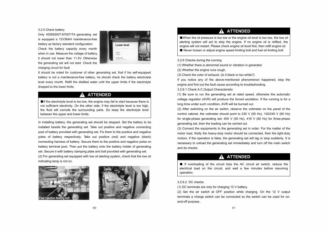
3.2.5 Check battery
Only KDE6500T-6700T/TA generating set
is equipped a 12V36AH maintenance-free
battery as factory standard configuration.
Check the battery capacity every month
when in use. Measure the voltage of battery,
it should not lower than 11.5V. Otherwise
the generating set will not start. Check the
charging circuit for fault.
It should be noted for customer of other generating set, that if his self-equipped
battery is not a maintenance-free battery, he should check the battery electrolyte
level every month. Refill the distilled water until the upper limits if the electrolyte
dropped to the lower limits.
In installing battery, the generating set should be stopped. Set the battery to be
installed beside the generating set. Take out positive and negative connecting
post of battery provided with generating set. Fix them to the positive and negative
poles of battery respectively. Take out positive (red) and negative (black)
connecting harness of battery. Secure them to the positive and negative poles on
battery terminal post. Then put the battery onto the battery holder of generating
set. Secure it with battery clamping plate and bolt provided with generating set.
(2) For generating set equipped with low oil alerting system, check that the low oil
indicating lamp is not on.
ATTENDED
If the electrolyte level is too low, the engine may fail to start because there is
not sufficient electricity. On the other side, if the electrolyte level is too high,
the fluid will corrode the surrounding parts. Do keep the electrolyte level
between the upper and lower limits.
3.2.6 Checks during the running
(1) Whether there is abnormal sound or vibration in generator.
(2) Whether the engine runs rough.
(3) Check the color of exhaust. (Is it black or too white?)
If you notice any of the above-mentioned phenomenon happened, stop the
engine and find out the fault cause according to troubleshooting.
3.2.6.1 Check A.C.Output Characteristic
(1) Be sure to run the generating set at rated speed, otherwise the automatic
voltage regulator (AVR) will produce the forced excitation. If the running is for a
long time under such condition, AVR will be burned out.
(2) After switching on the air switch, observe the voltmeter on the panel of the
control cabinet, the voltmeter should point to 230 V (50 Hz), 120/240 V (60 Hz)
for single-phase generating set; 400 V (50 Hz), 416 V (60 Hz) for three-phase
generating set, then the loading can be carried out.
(3) Connect the equipments to the generating set in order. For the matter of the
motor load, firstly the heavy-duty motor should be connected, then the light-duty
motors. If the operation is false, the generating set will lag or stop suddenly. It is
necessary to unload the generating set immediately and turn off the main switch
and do checks
3.2.6.2 DC checks
(1) DC terminals are only for charging 12 V battery.
(2) Set the air switch at OFF position while charging. On the 12 V output
terminals a charge switch can be connected so the switch can be used for on-
and-off purpose..
ATTENDED
When the oil pressure is too low or the engine oil level is too low, the low oil
alerting system will act to stop the engine. If no engine oil is refilled, the
engine will not restart. Please check engine oil level first, then refill engine oil.
Never loosen or adjust engine speed limiting bolt and fuel oil limiting bolt.
ATTENDED
If overloading of the circuit trips the AC circuit air switch, reduce the
electrical load on the circuit, and wait a few minutes before resuming
operation.

ATTENDED
Connect the positive and negative poles of the battery with the positive and
negative poles of DC terminals separately. Do not confuse them, otherwise the
generator and battery will burn out.
Do not contact the positive pole of the DC terminal with its negative pole,
otherwise the generating set damage will result.
Do not contact the positive pole of the battery with its negative pole,
otherwise the battery damage will result.
When a large capacity battery is charged, excessive current flows
(charging current should not exceed 8 A), the fuse for the direct current will
burn out.
Never run the generating set while it is still connected with the battery.
Never use DC 12 V and AC at the same time.
ATTENDED
Battery exhausts explosive gas. Keep sparks, flames, and cigarettes away
from the battery. To prevent from creating a spark near the battery, always
connect the charging cables to the battery first and only then to the generating
set. When disconnecting, you should disconnect the cables at the generating
set first.
Charge the battery at a well-ventilated place.
Before charging, remove the cap from each cell of the battery.
Stop charging if the electrolyte temperature exceeds 45 .
3.2.7 Check Overload Operation
Electrical appliance particularly motor-driven equipment will produce very high
current while starting, the table below provides the reference for connecting these
apparatus to the generating set in service by user.

3.2.8Check Stopping of Generating Set
(1)Disconnect the load from the generating
set.
(2)Turn off the air switch of the generating
set.
(3)Set the speed lever at RUN position,
run the generating set without load for
about 3 minutes. Do not stop the engine
suddenly, otherwise the temperature will
increase abnormally, the nozzle will
blocked and the generating set will be
damaged.
Press down the stop lever.
Concerning the electric starter, turn the key to OFF.
Turn the fuel cock lever to S position.
Pull out the recoil starter handle until you feel resistance (at this position, both
intake/exhaust valve are closed.) and leave the handle in this position. This
prevents the engine from rust.
If the engine keep on running even after the speed lever is placed at the
STOP position, either turn the fuel cock to the CLOSE position or loosen the
nut of high pressure fuel pipe on the pump side to stop the engine.
Do not stop the engine with the decompression lever.
Do not stop the generating set with load. Stop it after the load removed.
WARNING
4. MAINTENANCE
4.1 Oil-line and intake/exhaust parts
This section mainly deal with the actions which should be taken while a fault of
engine oil, oil quantity variation, air cleaner, oil line or oil tank presents.
(1) In case of excessive engine oil filled (exceeds 2/3) or white smoke emitted
from engine during generating set running, drain the oil.
(2) Refill engine oil to prescribed level. The low oil alert lamp will on and the
generating set will stop automatically.
(3) If the abnormal condition still presents, carry out the troubleshooting checks
for engine automatic stopping
4.1.1 Engine oil
Check oil level.
Check the engine oil level with the engine stopped and the generating set on a
level surface.
(1) Open the cabinet door.
(2) Remove the oil filler cap and check the oil level, note that the oil level should
be a bit lower the oil filler.
(3) If the oil level is low, refill oil to a position a bit lower the oil filler.
Check the stability of engine oil. Check that no impurity is adulterated.
Recommended engine oil: SAE10W-30 or SAE30, grade SE, SF, or SG of API
service classification.
Engine oil is the main factor to affect the engine service life. Use four-stroke
automatically purifying oil.
Recommended oil of SAE10W-30 is commonly used. When the average
temperature of user's area is within the applicable range for recommended
engine oil, the engine oil of other viscosity may be used.
Viscosity table.
(4) Tighten the oil filler cap.
4.1.2 Replace engine oil
Drain the oil while the engine is still warm, since hot oil is drained fast and
thoroughly.
(1) Remove service cap. Remove the oil filler cap. Drain the old oil into a suitable
container.
For environment protection it is recommended to put the waste engine oil in a
sealed container and delivery it to service station or recycle center of user's area.
Never pour the engine oil on the ground or debris.
Caution: The used engine oil contains cancerogenous substance. If contact with
skin frequently or for long time, skin cancer would be caused. Clean your hands
with soak thoroughly and rinse it immediately.

(2) Refill engine oil to specified position.
(3) check the oil level again after fueling;if oil level is too low, fuel to specified level.
(4) Reinstall the service cap.
(Fig.)Drawing of engine oil components
4.1.3 Oil tank/fuel oil filter
Cleaning:
(1) Remove the oil pipe from oil tank. Remove the fuel oil filter.
(2) Remove the clogging material in filter. Check the filter for damage. Replace if
necessary.
(3) Remove the oil tank. Clean it with detergent. After cleaning air dry completely,
then reinstall it.
(4) In quiet generating set, the cabinet must be removed.. Remove the oil tank.
Clean it with detergent. After cleaning air dry completely, then reinstall it.
(5) Reinstall the filter into oil tank. Connect oil pipe.
(6) Reinstall other parts in counter order for disassembling.
Refill the oil tank with diesel oil. Check the oil pipe for leakage.
4.1.4 Oil pipe/oil pump
(1) Check the oil pipe for deterioration, cracking, or leakage of diesel oil. If the oil
pipe has any abnormality, replace it.
(2) Check the magnet of pump for deterioration, cracking, or leakage of oil. If
there is any abnormality, replace the oil pump.
(3) Check for water accumulation or other foreign material in pump. If any,
replace pump.
(4) After assembling check all parts for leakage again.
Service: The fault phenomena is fluctuation of engine running or automatic
stopping -----fuel supply is insufficient or air presents.
Cause: Air presents in oil tank, oil pipe. Generally in new engine, or after oil-break
during running, a lot of air would be entered in engine pump or high pressure oil
pipe while fill oil.
Remedy:
(1)Stop the generating set. Check oil tank and oil pipe for oil-break;
(2)If oil-break happens, refill fuel oil.
(3)Loosen the circlip at the intake pipe of engine pump with a nipper pliers. Place
a container under the oil pump and oil pipe, discharge the air from oil pipe which
was entered in oil-break. Seeing oil flow out from oil pipe, connect the oil pipe to
the intake pipe of pump immediately and clip on.
Service: The fault phenomena is not starting or automatic stopping----------The oil
pump does not delivery oil.
Remedy:
(1)Loosen the discharging pipe at engine oil pump and high pressure oil pipe with
a open-end spanner.
(2)When starting open-shelf generating set by recoil or electric starter, pull out the
discharging pipe of oil pump. It is normal if there is oil in it. If no oil, replace the oil
pump.
(3)For quiet generating set check the 12V power supply first.
Checkout the voltage. Repeat the steps (1) and (2). Set the electric switch lock to
ON position. Checkout the 12V with a multimeter. If the 12V presents, replace oil
pump. If there is no 12V voltage, check the electric wiring and electric switch lock,
service according to the gauge panel.
Oil nozzleAir cleaner
Air-cooled diesel engineEngine oil drain screw
Engine oil filter
Oil pump
(Fig.) Drawing of oil tank
Oil leveller assembly
Screw M5x12 Filter cap assemblyFiller screen
Oil tank weldment
Oil nozzleBuckle II
High pressure oil pipe
Oil pump component
Fuel oil control valve component
Buckle I
Buckle I
Oil flter
Buckle I
Oil delivery pipeI
Buckle I
LiningDamping
sheath
Oil delivery pipe II
Oil return pipe
Oil tank compont
Bolt
(Fig.) Electric switch lock
1 2 3 4 5offonstart
1 43
5 2

4.1.5 Air cleaner
A dirty air cleaner will obstruct air from entering carburetor, thus reduces the
engine working efficiency. If the engine is running in dusty area, clean the air
cleaner more frequently.
Caution: Never run the engine without the element or with a defective element,
the dirt may enter into engine to accelerate the engine damage.
Checking/cleaning:
(1) Loosen screws on service cap, remove the service cap.
(2) Push off the locking plate on the top of air cleaner, remove the air cleaner.
(3) Take out the filter element.
(4) Wash the element in warm soap water, rinse it and air dry completely. Or
clean with high fire point solution and air dry.
Soak the element in clean engine oil, squeeze out redundant engine oil. The
redundant engine oil may prevent air to enter into foam element and would smok
at engine starting.
(5) Reinstall the element in air cleaner. If necessary, clean the air cleaner rubber
and housing. Make sure that the seal ring of air cleaner cover is secured.
(6) Reinstall the air cleaner cover. Reinstall parts in order. Lock the locking plate
on the top of air cleaner. Make sure that the seal ring of air cleaner cover is
secured. If the seal ring of air cleaner cover is damaged, replace it.
(7) Reinstall the service cap.
Caution: If the cover of air cleaner installed not tightly, it would fall during engine
running due to vibration. Never run the engine without air cleaner or with a
defective air cleaner to prevent accelerated wear of engine.
Service: The fault phenomena is fluctuation of engine running and incapable of
power raising-------insufficient air intake.
Cause: (1) Dirty air enters; (2) Exhaust gas feedbacks during engine running,
which causes incomplete combustion in engine and carbon deposition on oil
nozzles.
Remedy: Repeat the above-mentioned steps for cleaning. Refer to engine service
for oil nozzle faults.
4.1.6 Muffler
a. Removing and reinstalling
Caution: Remove and reinstall the muffler after the engine is cooled down.
(1)Protective hood of muffler
In quiet generating set the cooling plate must be removed, then remove the
muffler.
(2)Muffler (Installation: Before installing, tap muffler with a plastic hammer to
remove internal carbon deposition.)
(3)Gasket of muffler (Can not be reused)
Service 1: The fault phenomena is black smoke emitted from exhaust port during
engine running -------insufficient air intake.
Cause: (1) Dirty air enters; (2) Exhaust gas feedbacks into air cleaner during
engine running, which causes incomplete combustion in engine and carbon
deposition on oil nozzles.
Remedy:Repeat the above-mentioned steps for cleaning. Refer to engine service
for oil nozzle faults.
Service 2: The fault phenomena is black smoke emitted from exhaust port during
engine running ------generating set is overloaded
Cause:1.Generating set is overloaded. 2.Engine oil nozzle and oil pump have
faults causing incomplete combustion in engine and carbon deposition on oil
nozzles.
Remedy: 1.Repeat the above-mentioned steps for cleaning. 2.Reduce the loading
power of generating set. 3. Refer to engine service for oil nozzle faults.
4.2 Control panel
This section mainly deal with the remedy for faults caused by air switch, voltmeter,
electric switch lock, receptacle or PCB in control panel, and actions which should
be taken while the generating set faults such as no voltage output, no voltage
indication, not starting, automatic stopping, etc. present.
4.2.1 A.C. receptacle
Check: Connect two poles of receptacle with a jumper. The current should flow
normally between conductor terminals. There is current passed between
receptacle ground terminal and receptacle installing set.
Air cleaner
Right side plate Cover plate of cleaner
(Fig.) Cleaning of air cleaner
Nut
Tail-gas turning weldment
Plain washer
BoltM6x30
Second stage muffler assembly
Bolt M8x30
Bolt M8x16
First stage muffler assembly
Exhaust pipe assembly
Nut M8
Buckle I
Spring washerPlain washer
Gasket for exhaust pipe
(Fig.) Muffler

Service 1: The fault phenomena is no voltage output in generating set.
----Receptacle terminal is loosened, receptacle terminal is melted.
Cause: 1.Wring is loosened due to vibration. 2. Receptacle patchplug is loosened
to result in heating up
Remedy: 1. Add glue. 2. Replace plug and receptacle.
4.2.2 D.C. receptacle or post
Check: Connect two poles or posts of receptacle with a jumper. Open the circuit
breaker (if any), the current should flow normally between conductor terminals.
Service 1: The fault phenomena is no voltage output in generating set.
----Receptacle terminal is loosened, receptacle terminal is melted.
Cause: 1. Wring is loosened due to vibration. 2. Receptacle patchplug is
loosened to result in heating up
Remedy: 1. Add glue. 2. Replace plug and receptacle.
4.2.3 Starting switch
Check: Circuit should be closed when switched on. Circuit should be open when
switched off. In starting position the circuit should be closed.
Service 1: The fault phenomena is incapable to switch on, start or stop.------------
Receptacle terminal of switch is loosened, switch contact is melted.
Cause: 1. Wring is loosened due to vibration.
2. Switch patchplug is loosened, result in heating up
Remedy: 1. Checkout the resistance for each switch position with a multimeters.
The on-off relation should comply with the table above, otherwise there would be
fault.
2. Replace patchplug and electric door lock.
(Fig.) Position of electric switch lock
OFF
ON
START
1 2 3 4 5 6 7
(Fig.) Panel
1 2 3 4 5offonstart
1 43
5 2
Low-oil alert lamp Voltmeter
Electric switch lock
Four-holereceptacleof americanstyle
Combined receptacle of american style
Grounding bolt
Electric switch lock Voltmeter
Combinedreceptacleof american style
Air switch
DC receptacle
Intelligent display
Fuse base
Low oil alert lampVoltmeter
Air switch
DC receptacle
Air switch
Electric switch lockDC terminal post
Combined receptacle of american style
Three-holereceptacleof americanstyle
Four-holereceptacleof americanstyle
Grounding bolt
Electric switch lock DC receptacle
Air switch
Four-holereceptacleof americanstyle
Grounding bolt Combined receptacle of american style
Three-holereceptacleof americanstyle
Three-holereceptacleof americanstyle
Four-holereceptacleof americanstyle
Grounding bolt
Electric switch lock DC receptacle
Air switchIntelligent display
Fuse base Grounding bolt
Three-phase five-holereceptacle of english style
Honda receptacle

4.2.4 Voltmeter
Check: Connect electric supply , which voltage range is the same as voltmeter, to
the terminal post of voltmeter. The voltmeter should indicate normal voltage.
Service: Fault phenomena is that there is AC current output during generating set
running, but no AC voltage indication.-----------The voltmeter is open-circuit, the
wring of voltmeter is loosened.
Cause: 1. Wring is loosened due to vibration. 2. The element in voltmeter is
damaged. 3. The pointer of voltmeter is seized.
Remedy: 1. Checkout the resistance on voltmeter terminal posts with a
multimeter for on-off relation. On is normal. Off is faulty. 2. Replace voltmeter.
Cause: 1. The generator does not generate power.
Remedy: According the troubleshooting for generator.
4.2.5 Air switch
Check: Checkout the resistance at two ends of air switch with a multimeter. The
resistance should be infinity in OFF and zero in ON.
Service 1: The fault phenomena is that there is AC current output during
generating set running, but no AC voltage indication.-----The voltmeter is open-
circuit, the wring of voltmeter is loosened.
Cause: 1. Wring is loosened due to vibration. 2. The element in voltmeter is
damaged. 3. The pointer of voltmeter is seized.
Remedy: 1. Checkout the resistance on voltmeter terminal posts with a
multimeter for on-off relation. ON is normal. OFF is faulty. 2. Replace voltmeter.
4.2.6 PCB parts for engine oil alarming and stopping
Check: Checkout the contact and circuit of relay on PCB with a multimeter for
correct on-off.
Service 1: The fault phenomena is low oil pressure indication alarming.-----The
indicating lamp on PCB always on.
Cause: 1. The engine oil filter is dirty, result in false alarm of engine oil. 2. The
relay on PCB is defective.
Remedy: 1. Checkout the resistance of two harnesses at the terminal post of
alarming apparatus for on-off relation. Off is normal. On is faulty. 2. Replace
PCB. 3. Replace relay, or 4.Replace engine oil alarming apparatus.
Service 2: The fault phenomena is automatic stopping during generating set
running.----------The relay on PCB is damaged.
Remedy: 1. Checkout the resistance of two harnesses at the terminal post of
alarming apparatus for on-off relation. Off is normal. On is faulty. 2. Replace
PCB. 3. Replace relay, or 4.Replace engine oil alarming apparatus.
Plug
Screw M6x12
AC receptacle
Fuse baseElectric switch lock
Intelligent display
Grounding nut
Air switch
Receptacle Plastic Veneer
Panel
Honda receptacle
Gauge panel Three-phase generating set
Gauge panel Three-phase generating set
Plug
Boat switch
Electric switch lock
DC receptacle
Fuse base
Air switch
Grounding nutScrew
Plastic veneer
Panel
Grounding bolt
Air switchReceptacle
Nut
Intellgent display
Electric switch lock

4.3 Generator
4.3.1 Generator
Check
(1) Front end cover: Check for cracking
(2) Generator fan: (Take care not to damage the fan blade in disassembling and
assembling)
(3)Rotor: Remove engine oil and contaminant on surface part before
installation. Normal measured resistance should comply with table 2.9. The color
should be red brown. In case of burn-out by short circuit, it would become black
and cracking would present. Then the rotor should be replaced.
(4)Clip ring: It should be smooth without any defect or distortion. The semicircle of
center boss should be clear. In case of distortion the clip ring should be replaced.
(5)Through stud: Locking torque is 50-55 Nm. If locked not tightly, the generator
would be damaged by scrubbing of rotor and stator.
(6)Stator: Check the external enamel covered wire for defect in disassembling
and assembling. Do not contact the copper wire part with ground or sharp metal
part directly to prevent scuffing.
(7)Stator lead-out: Divided into main winding, secondary winding, sampling
winding and 12V low voltage winding. Checkout the resistance of each winding, it
should be same as the parameter in table 2.9. Otherwise the stator should be
replaced.
(8)Carbon brush: There should be no open-circuit between lug and pole of carbon
brush, and no short-circuit between two poles.
(9)Rear end cover: Check for cracking.
Disassembling/assembling
(1)Open the rear end cover for open-shelf generating set. Remove the cabinet,
cooling plate, left and right side plate, and muffler for quiet generating set.
(2)Remove the generator with wiring. In quiet generating set must remove the
induced draft hood, then remove the harness.
(3)Remove 4XM6X175M bolt of rear end cover.
(4)Take out the stator.
(5)Fix the rotor with a belt spanner, then remove 10MM flange bolt.
Caution: Never knock the nut or rotor with hammer etc.
(6)Remove the rotor with a flywheel drawer.
4.3.2 Installation of rotor
Caution: Remove the dust and oil pollution from the crankshaft and rotor part.
Check the magnetic part of rotor for attachment of metallic material or gasket.
(1)Insert the semicircle clip ring into key groove.
(2)Install the rotor on the crankshaft.
(3)Fix the rotor with a belt spanner, secure the 10MM flange bolt to specified
torque.
Tightening torque: 50 Nm (5.0 kgf.m, 37.5 lbf.ft)
4.3.3 Stator
If measured resistance exceeds above-mentioned specified value, check the
harness of generator. Replace the harness of generator if necessary. If the
harness of generator is regular, replace the stator assembly.
Secondary winding:
Checkout the resistance between two blue (green) terminals of four-position
connector. See table 2.9 for the resistance value.
If measured resistance exceeds above-mentioned specified value, check the
harness of generator. Replace the harness of generator if necessary. If the
harness of generator is regular, replace the stator assembly.
AC winding:
Checkout the resistance of main winding on four-position terminal board.
The resistance value between (red, white, green) terminals in 120V/240V
simultaneous output.
In 120V/240V selected output the resistance for (brown, black, red, blue)
terminals which are (L1, L2; R1, R2) respectively.
If measured resistance exceeds specified value in table 2.9, check the harness of
generator. Replace the harness of generator if necessary. If the harness of
generator is regular, replace the stator assembly.
12V low voltage winding:
Checkout the resistance between the green terminals on four-position connector.
If measured resistance exceeds specified value in table 2.9, check the harness of
generator. Replace the harness of generator if necessary. If the harness of
generator is regular, replace the stator assembly.
Sampling winding:
Checkout the resistance between the yellow terminals on four-position connector.
If measured resistance exceeds specified value in table 2.9, check the harness of
generator. Replace the harness of generator if necessary. If the harness of
generator is regular, replace the stator assembly.
B. Adjustment
The spacing between the stator winding and rotor.
Insert a feeler between the stator winding and the projection of rotor. Push the
rotor winding to 90 , 180 , 270 , 360 . The rotor rotate for one turn. Secure
the flange bolt connecting stator and front end cover. The locking torque is 10-13
Nm (1.0 kgf.m, 7.5 lbf.ft). Spacing: 0.25 +/- 0.1 mm (0.020+/-0.004 in)

Service: The fault phenomena is: no voltage, no power output, scrubbing of stator
and rotor, generator burn-out, generating set does not start.
Cause: 1. Open circuit of winding, 2. Short circuit of winding, 3. Carbon brush
wearing, 4. Fixing parts loosened due to vibration, 5. Front and rear end covers
cracking, 6. Seizing of stator and rotor, 7. Engine crankshaft bearing wearing
Remedy: 1. Avoid overloading and ventilate to cool down, 2. Replace carbon
brush, 3.Replace generator, 4. Secure the connecting parts, 5. Replace front
and rear end covers.
4.4 Cabinet
4.4.1 Right side plate
Check: Check the inlet and outlet of air duct on right side plate to ensure
ventilation. Each sound absorbing sponge should be clog-free.
Service: 1. The fault phenomena is insufficient AC current output during
generating set running------Air duct clogged. 2. High temperature of engine
Cause: 1. Vibration 2. The sponge falls off by the effect of temperature.
Remedy: 1. Replace sponge
4.4.2 Left side plate, cooling plate
Check: Check the inlet and outlet of air duct on left side plate to ensure ventilation.
Each sound absorbing sponge should be not clogged or fall off.
Service: 1. The fault phenomena is insufficient AC current output during
generating set running------Air duct clogged. 2. High temperature of engine 3.
High temperature of exhaust pipe
Cause: 1. Vibration 2. The sponge falls off by the effect of temperature.
Remedy: 1. Replace sponge. 2. Replace heat insulating material.
4.4.3 Cabinet
Check: Check the inlet and outlet of air duct on cabinet to ensure ventilation.
Each sound absorbing sponge should be not clogged.
Service: 1. The fault phenomena is insufficient AC current output during
generating set running------Air duct clogged. 2. High temperature of engine 3.
High temperature of exhaust pipe
Cause: 1. Vibration 2. The sponge falls off by the effect of temperature.
Remedy: 1. Replace sponge. 2. Replace heat insulating material.
4.4.4 Transformer in cabinet
Check: Checkout the resistance at two terminals of transformer with a multimeter.
Closed circuit is normal. Open circuit is faulty. The transformer is installed only in
model KDE6700TA. In other model there is no transformer.
Service: The fault phenomena is no voltage indication during generating set
running or a code of P-03 present..--------------Open circuit or short circuit of
transformer.
Cause: 1. Vibration. 2. Fixing parts loosened or fall off.
Remedy: 1. Replace transformer.
4.4.5 Chassis
Check: Check the inlet and outlet of air duct to ensure ventilation. Each sound
absorbing sponge should be not clogged.
Service: 1. The fault phenomena is that the wheel falls off during generating set
running. 2.Air duct clogged.
Cause: 1.Vibration. 2. Fixing parts loosened or fall off.
Remedy: 1. Replace wheel. (Only in model KDE6700T/TA/TA3 have to remove
the cabinet of generating set)
Bolt M5x18
Weldment of induced draft casing
Screw M5x14
Carbon brush
Rear end cover
Bolt M5x16Rectifier
Bolt M6x175(Locking front end cover) torque:10-13Nm
Bolt M5x18
Main winding
Yellow:sampling
Round nut
Stator
Bolt M10(Locking torque:50-55Nm)Washwr
Bolt M8x30
Front end cover
Fan
Rotor
Clip ringBlue(or green):secondry winding
(Fig.) Components of electric machine
Rubber wheel
Chassis

(Fig.) Cabinet (1), (2), (3)
Cooling plate
Left side plate
Fixing sheath for sight window
Buoy sight window
Shock pad of oil tank
Bolt M6x16
Bolt M6x16Spring washer 6 Bolt M6x16
Big washer 6
Rear door weldment
Bolt M6x16
Bolt M5x15
Shock pad of air cleaner port
Bolt M5x12Spring washer 5
Closing plate of air cleaner
Transtormer
Cabimet weldment
Bolt M6x20Spring washer
Bolt M6x20 Big washer 6
Bolt M6x20Spacer
Reinforced plate for door lock
Nut M4Door Lock Bolt M5x10
Bolt M5x15Knob of door lock
Right side plateCover plate
of air cleaner

5. SERVICE OF INTELLIGENT CONTROL PANEL
(Fig.) Intelligent control panel
To regulate curret of protected point
To regulate current of phase C
To regulate current of phase B
To regulate current of phase A
To regulate voltage of phase C or line CA
To regulate voltage of phase B or line BC
To regulate voltage of phase A or line AB
1: Frequency setting
2 3:Voltage setting (2:ON 3:ON)--230V
(2:OFF 3:ON)--240V
(2:ON 3:OFF)--115V
(2:ON 3:ON)--230V
(2:OFF 3:OFF)--120V
(4:ON 5:ON)--single phase
(4:OFF 5:ON)--double voltage
selected output
(4:ON 5:OFF)--double voltage
simultanceous output
(4:OFF 5:OFF)--three phase
Toggle switch for function setting
Charging checkout, negative
Common terminal fur output
Starting output
Fuel oil control output
Power supply input, positive
Protection input(low is valid)
Starting signal (high is valid)
Input terminal 2 for current of phase C
Input terminal 2 for current of phase B
Input terminal 2 for current of phase A
Phase B voltage input (the phase-voltage)in transforned)
Phase A voltage input (teh phase-voltage) in transforned)
Charing checkout, position
Common terminal for output
Stating output
Power supply input
Voltage selection 120/240
Engine oil alarming input(grounding is valid)
Input termianl 1 for current of phase C
Input termianl 1 for current of phase B
Input termianl 1 for current of phase A
Common torminal for voltage input
Phase C voltage input (the phase-voltage is transformed)Both pin of common terminal
starting motor to be connected
Diagram of starting motor fuel
oil control
Plug
Boat switch
Intelligent display
Electric switch lock
DC receptacle
Fuse base
ScrewGrounding nut
Panel
Grounding bolt
Plastic veneer
Air switch Receptacle
Nut
Electric switch lock
Chinese PVC veneer English PVC veneer
PVC circuit board on module exterior

(7) Press and hold down key "FUN", Turn the electric switch lock from OFF to ON. After 5
seconds enter setting program. Start generating set. The protection function for electrical
parameters will be revoked
(8) Charge and checkout the toggle switches as table below
Warning: Do not adjust this switch. It is adjusted in factory. The user and
maintenance person should not vary the settings.
5.2 Checks
Starting check
(1) Turn the electric switch lock from OFF to ON. The rated current of generating
set output is displayed in display window. After 0.1-0.5 seconds the output voltage
will displayed (at this point the voltage is zero).
(2) Turn the electric switch lock from ON to ST. "STArt" will displayed in display
window. The starting motor drive the engine to start.
Display of electrical parameters
(1) After starting of generating set the voltage indicating lamp will on. The output
voltage is displayed in display window. According to different phase number of
output the voltage will be displayed as follows:
5.1 Setting
(1) Press and hold down key "FUN", turn the electric switch lock from OFF to
ON. After 5 seconds enter the setting program.
(2) According to the number of voltage phases and the table below select
corresponding toggle switch.
(3) Press key "FUN" to enter frequency setting. According to the frequency of
output voltage and table below select corresponding toggle switch.
(4) Press key "FUN" to enter voltage setting. According to the output voltage
and table below select corresponding toggle switch.
(5) Press key "FUN" to enter current setting. Display IXXX.X. Regulate the potentiometer
I_set to vary displayed value. Clockwise to decrease and counterclockwise to increase. The
minimum variation is 0.3. Set the current value to rated current..
(6) After setting:
a. Start generating set directly. At this point the protection function for electrical parameter is
revoked.
b. Turn the electric switch lock from ON to OFF, then restart generating set.
Ph
ase
nu
mb
er
se
ttin
g
DisplayToggle switch DIP4
Toggle switch DIP5
Toggle switchDIP4 DIP5
Left Right Left RightMeaning
PH-1
PH-2
PH=2
PH-23
ON ON
ON OFF
ON OFF
OFF OFF
Single phase single voltage outputON OFF
ON OFF
ON OFF
ON OFF
OFF ON
OFF ON
OFF ON
OFF ON
Double voltage selected output
Three-phase output
Double voltageselected output
MeaningToggle switch DIPIToggle switch DIPIDisplayFrequency
settingF-60
F-50
ON
OFF
Left Right
Left Right
Frequency of output voltage is 60 Hz
Frequency of output voltage is 50 Hz
Toggle switch DIP2
Toggle switch DIP3
MeaningToggle switch
DIP2 DIP3Left Right Left Right
Display
Vo
lta
ge
se
ttin
g
OFF
ON
OFF
ON
OFF
OFF
ON
ON
ON OFF
ON OFF
ON OFF
ON OFF
ON OFF
ON OFF
ON OFF
ON OFF
U-120
U-115
U-240
U-230
Output voltage 120
Output voltage 115
Output voltage 240
Output voltage 230
Type of engine
5KW diesel
DIP1(three positions) Remark (three position toggle switch) DIP2(three positions) DIP3(three positions)
OFF ON ON According to the voltage of flywheel generator
Double voltage selected output
Display
Display output voltage
Display actual output voltage according to various selection
Double voltage simult-
aneous output
Three-phase output
Phase number
Single phase single voltage
Display "AbXXX", in which the XXX is voltage value, display voltage value of line AB. Press key FUN to display"bCXXX", in which the XXX is voltage value, display the voltage value of line BC. Press key FUN to display "CAXXX", in which the XXX is voltage value, display the voltage value of line CA
Display "AXXX.X", in which the XXX.X is voltage value, display the high voltage
value of output. Press key FUN to display "bXXX.X", in which the XXX.X is
voltage value, display a lower voltage value of output. Press key FUN to display
"CXXX>X", in which the XXX.X is voltage value, display another lower voltage
value of output.

Press key FUN, the current (power) indicating lamp will on. The output current
(power) is displayed in display window. According to different phase number of
output display current (power) as follows:
(3)Press key FUN, the frequency indicating lamp will on, the output frequency is
displayed in display window.
(4)Press key FUN, the running indicating lamp will on, the accumulated running
time (hrs) is displayed in display window.
(5)Press key FUN, the battery indicating lamp will on, the voltage of battery is
displayed in display window..
(6)Press key FUN, the voltage is displayed in display window.
Display electrical parameters in turn
(1)Enter in-turn display
After starting of generating set, press and hold down the key FUN for 2 seconds.
The electrical parameters will be in turn displayed in display window in following
sequence:
Voltage------Current(power)------Frequency------Running time------Voltage of
battery--- Voltage
(2) Exit in-turn display
In in-turn display condition press and hold down FUN for 2 seconds to exit in-turn
display.
Stopping
Turn the electric switch lock from ON to OFF to stop the generating set.
5.3 Maintenance
Fault code display and actions to be taken (factory default)
Code display
P-01
P-02
P-03
P-04
P-05
Insufficient engine oil pressure.
Sustain for 5 seconds, then
stop
Meaning
1.Check engine oil
2.Check fuel oil
3.Check engine oil sensor
4.Check oil line for air
5.Check connecting wire
RemarkAction to be taken
Frequency exceeds 55 Hz
or 65 Hz. Sustain for 5
seconds, then stop
1.Check oil line for air
2.Check fuel oil
3.Check engine governor
4.
Output voltage exceeds 110%
of rated voltage. Sustain for 3
seconds, then stop
1.Check generator output voltage
2.Check AVR
3.Check generator carbon brush
4.
5.Check transformer unit
6.Check fuel oil
7.Check oil line for air
Overloading: Load exceeds
110% of rating, sustain for
60 seconds, then stop; load
exceeds rating but less than
110% of rating, sustain for 60
min. then stop
1.Check load for overloading
2.
3.Check generator
4.Check current transformer
5.Check oil line for air
Check frequency of generator output voltage
Check generator sampling winding
Check output circuit for short circuit
Charging fault 1.Check battery
2.Check charger
3.
4.Check fuel oil
5.Check oil line for air
Check charging generator (flywheel generator)
Display power (VA)
Display power (VA)
Display power (VA)
Three-phase output
DisplayPhase number
Single phase single voltage
Double voltage selected output
Double voltage simultaneous output
Display "AXXX.X", in which the XXX.X is current value, display the current value of phase A. Press key FUN to display "bXXX.X", in which the XXX.X is current value, display the current value of phase B. Press key FUN to display"CXXX.X", in which the XXX.X is current value, display the current value of phase C.

Code display
P-01
P-02
P-03
P-04
P-05
Meaning
6.Check engine oil
7.Check fuel oil
8.Check engine oil sensor
9.Check oil line for air
10.Check connecting wire
RemarkAction to be taken
5.Check oil line for air
6.Check fuel oil
7.Check engine governor
8.
8.Check generator output voltage
9.Check AVR
10.Check generator carbon brush
11.
12.Check transformer unit
13.Check fuel oil
14.Check oil line for air
6.Check load for overloading
7.
8.Check generator
9.Check current transformer
10.Check oil line for air
Check frequency of generator output voltage
Check generator sampling winding
Check output circuit for short circuit
6.Check battery
7.Check charger
8.
9.Check fuel oil
10.Check oil line for air
Check charging generator (flywheel generator)
Fault code display and actions to be taken (default for 5 KW special requirement
in North America)
Insufficient engine oil pressure.
Sustain for 5 seconds, then
stop
Frequency 65 Hz. Sustain
for 3 seconds, then stop.
Frequency 57 Hz Sustain
for 20 seconds, then stop.
Voltage 132V (264V),
Sustain for 3 seconds, then
stop. Voltage 105V (210V),
Sustain for 20 seconds, then
stop
Overloading: Load exceeds
rated 21.2A, sustain for 60
seconds, then stop. Load
exceeds rating, in 19.2A-
21.2A, sustain for 60 min.
then stop
Charging fault, display with-
out protection
Note:
(1) At protection of generating set the protected object and protection code are
displayed alternately in display window.
(2) When protection stopping happens, you can press key FUN to inquire the
parameters before protection.
(3) Do not remove battery during generating set running, otherwise the electrical
device may be damaged.
(4) When stopping happens due to burn-out of fuel oil, the protection of P-01, P-
02, P-03, P-04, P-05 will happen because of air in oil line. The air would be
discharged completely after several times of restarting. If necessary, the oil line
should be treated with air-bleeding for normal running of generating set. After
starting the generating set may run unstably. Run generating set without load for
5 min., then the generating set will resume to normal running.
(5) When start with insufficient electricity of battery, the display screen may be
abnormal and the generating set will not start. Charge the battery or replace with
a new battery.
(6) The DIP switches on panel are set in factory. Do not vary the settings by
unprofessional person. If varied, the panel would not work abnormally.
5.4 Parameter setting list
Three-phase output
Output frequency 60 Hz
Output frequency 50 Hz
Output voltage 115V
Output voltage 120V
Output voltage 230V
Output voltage 240V
Rated current
Item Display Toggle switch Meaning Remark
Phase number setting
Frequency
Output voltage
PH-1
PH-2
PH-2
PH-3
F-60
F-50
U-115
U-120
U-230
U-240
I____Rated current
DIP4 ON, DIP5 ON
DIP4 OFF, DIP5 ON
DIP4 ON, DIP5 OFF
DIP4 OFF, DIP5 OFF
DIP1 ON
DIP1 OFF
DIP2 ON, DIP3 OFF
DIP2 OFF, DIP3 OFF
DIP2 ON, DIP3 ON
DIP2 OFF, DIP3 ON
Double voltage simultaneous output
Single phase single voltage output
Double voltage selected output
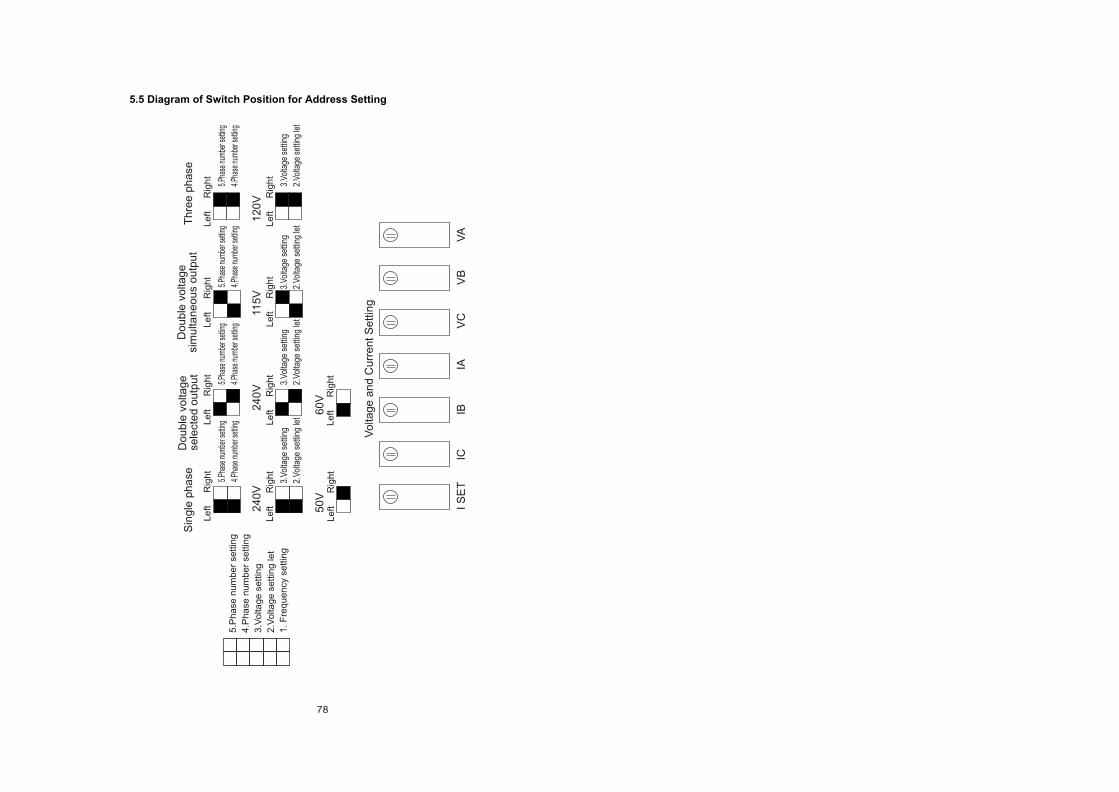
5.5 Diagram of Switch Position for Address Setting
5.P
ha
se n
um
be
r se
ttin
g
4.P
ha
se n
um
be
r se
ttin
g
3.V
olta
ge
se
ttin
g
2.V
olta
ge
se
ttin
g le
t
1. F
req
ue
ncy s
ettin
g
5.Ph
ase
num
ber s
ettin
g
4.Ph
ase
num
ber s
ettin
g
5.Ph
ase
num
ber s
ettin
g
4.Ph
ase
num
ber s
ettin
g
5.Ph
ase
num
ber s
ettin
g
4.Ph
ase
num
ber s
ettin
g
5.Ph
ase
num
ber s
ettin
g
4.Ph
ase
num
ber s
ettin
g
3.Vo
ltage
set
ting
2.Vo
ltage
set
ting
let
3.Vo
ltage
set
ting
2.Vo
ltage
set
ting
let
3.Vo
ltage
set
ting
2.Vo
ltage
set
ting
let
3.Vo
ltage
set
ting
2.Vo
ltage
set
ting
let
Sin
gle
ph
ase
D
ou
ble
vo
ltag
e
sele
cte
d o
utp
ut
Do
ub
le v
olta
ge
si
mu
ltan
eo
us
ou
tpu
tT
hre
e p
ha
se
24
0V
2
40
V 11
5V
1
20
V
50
V 6
0V
Le
ft R
igh
tL
eft R
igh
tL
eft R
igh
tL
eft R
igh
t
Le
ft R
igh
tL
eft R
igh
tL
eft R
igh
tL
eft R
igh
t
Le
ft R
igh
tL
eft R
igh
t
Vo
ltag
e a
nd
Cu
rre
nt S
ettin
g
I S
ET
IC
IB
IA
V
C V
B V
A