MAINTENANCE INSTRUCTIONS - idealvac.com · PASCAL SERIES Rotary vane pumps 5 to 21 m3/h . EN – 1...
45
MAINTENANCE INSTRUCTIONS MAINTENANCE INSTRUCTIONS EN EN Translation of the original instructions Translation of the original instructions PASCAL SERIES PASCAL SERIES Rotary vane pumps 5 to 21 m Rotary vane pumps 5 to 21 m 3 3 /h /h
Transcript of MAINTENANCE INSTRUCTIONS - idealvac.com · PASCAL SERIES Rotary vane pumps 5 to 21 m3/h . EN – 1...
MAINTENANCE INSTRUCTIONSMAINTENANCE INSTRUCTIONS ENEN
Translation of the original instructionsTranslation of the original instructions
PASCAL SERIESPASCAL SERIESRotary vane pumps 5 to 21 mRotary vane pumps 5 to 21 m33/h /h
EN – 1
Main
ten
an
ceN
om
en
clatu
reEN
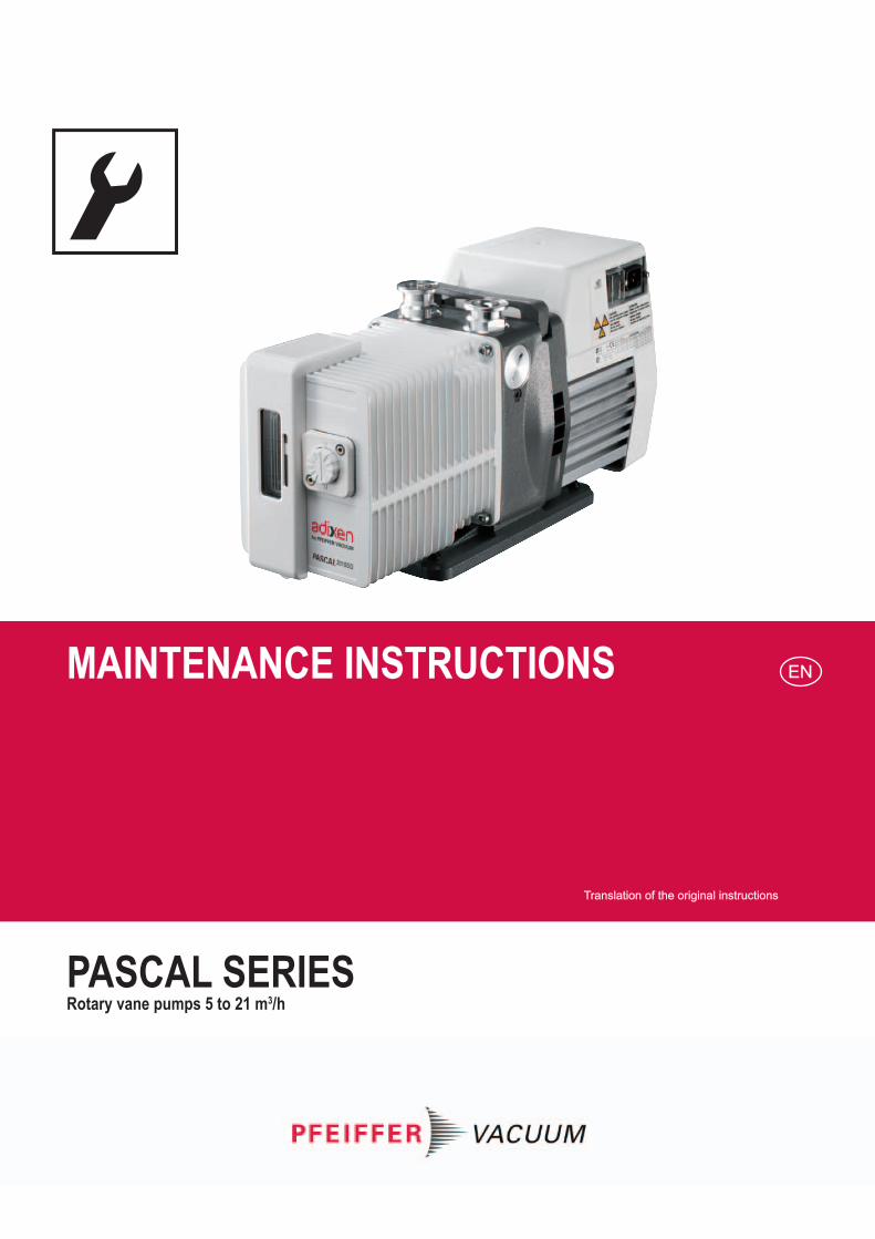
Rotary vane pumps
Dear customer,
This Maintenance instructions is intended for customers of the Pfeiffer Vacuum Company.It describes the product maintenance operations which can be performed by the user on the product concerned. This documentation must be used together with the operating manual for the product of the same name.
MaintenanceSafety instructions for maintenance ............................................................ 3Tools and consumable products .................................................................. 4Replacement of external shaft seal.............................................................. 7Disassembling the pump ............................................................................. 8Cleaning components ................................................................................. 13Replacement of shaft seals ......................................................................... 14Reassembling the pump .............................................................................. 15
Service ....................................................................................................... 19
NomenclatureSpare parts lists ............................................................................N - 1 à N - 23
EN – 2
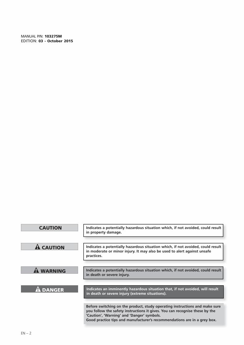
Indicates a potentially hazardous situation which, if not avoided, could result in moderate or minor injury. It may also be used to alert against unsafe practices.
Indicates a potentially hazardous situation which, if not avoided, could result in property damage.
Indicates an imminently hazardous situation that, if not avoided, will result in death or severe injury (extreme situations).
Indicates a potentially hazardous situation which, if not avoided, could result in death or severe injury.
Before switching on the product, study operating instructions and make sure you follow the safety instructions it gives. You can recognise these by the ‘Caution’, ‘Warning’ and ‘Danger’ symbols. Good practice tips and manufacturer’s recommendations are in a grey box.
MANUAL P/N: 103275MEDITION: 03 - October 2015
EN – 3
EN
Main
ten
an
ce
General precautions
Safety instructions for maintenance
For normal operation, the maintenance of 5 to 21 m3/h series pumps only require regular oil changes (see Operating instructions).
Insufficient tightness after servicing could result in chemical hazards. Always perform a leak test after maintenance.
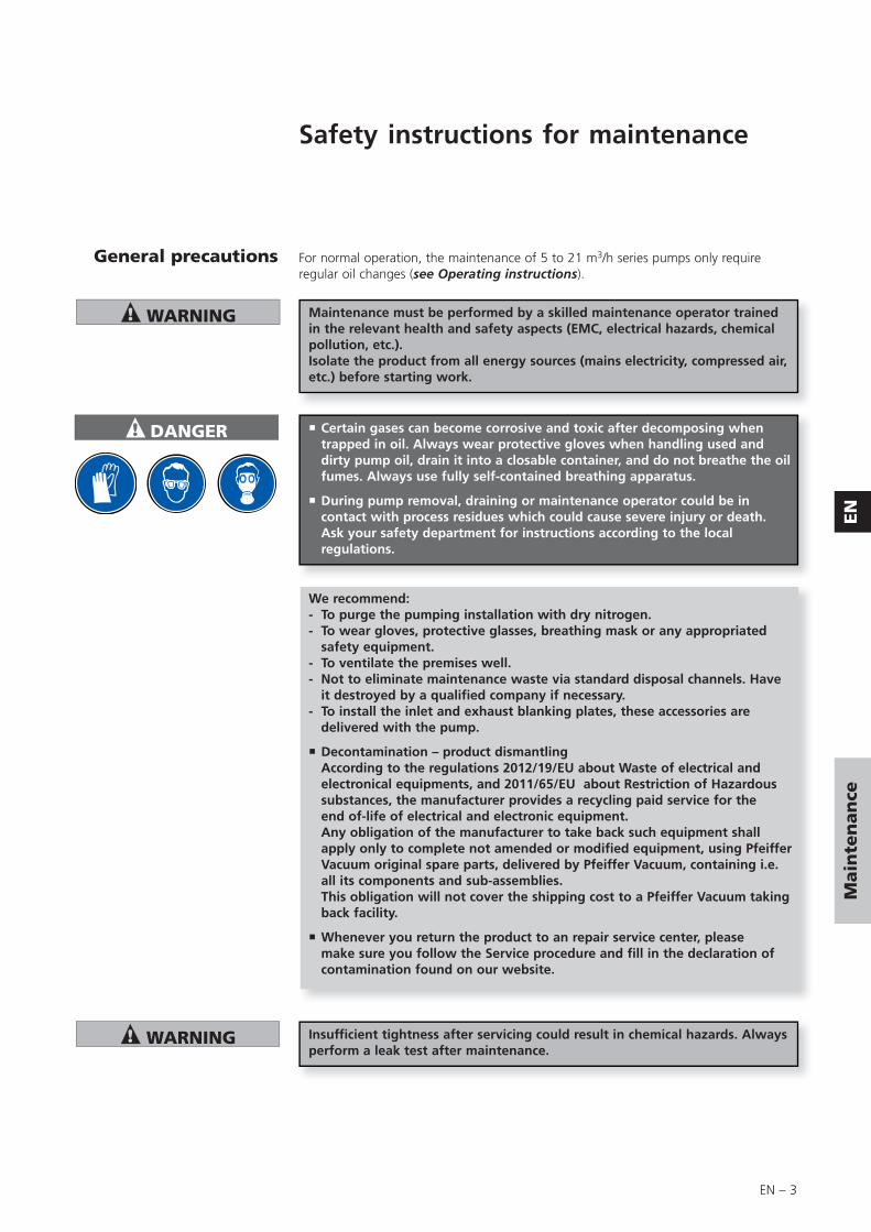
Certain gases can become corrosive and toxic after decomposing when trapped in oil. Always wear protective gloves when handling used and dirty pump oil, drain it into a closable container, and do not breathe the oil fumes. Always use fully self-contained breathing apparatus.
During pump removal, draining or maintenance operator could be in contact with process residues which could cause severe injury or death. Ask your safety department for instructions according to the local regulations.
We recommend:- To purge the pumping installation with dry nitrogen.- To wear gloves, protective glasses, breathing mask or any appropriated
safety equipment.- To ventilate the premises well.- Not to eliminate maintenance waste via standard disposal channels. Have
it destroyed by a qualified company if necessary.- To install the inlet and exhaust blanking plates, these accessories are
delivered with the pump.
Decontamination – product dismantlingAccording to the regulations 2012/19/EU about Waste of electrical andelectronical equipments, and 2011/65/EU about Restriction of Hazardoussubstances, the manufacturer provides a recycling paid service for theend of-life of electrical and electronic equipment.Any obligation of the manufacturer to take back such equipment shallapply only to complete not amended or modified equipment, using Pfeiffer Vacuum original spare parts, delivered by Pfeiffer Vacuum, containing i.e. all its components and sub-assemblies.This obligation will not cover the shipping cost to a Pfeiffer Vacuum taking back facility.
Whenever you return the product to an repair service center, please make sure you follow the Service procedure and fill in the declaration of contamination found on our website.
Maintenance must be performed by a skilled maintenance operator trained in the relevant health and safety aspects (EMC, electrical hazards, chemical pollution, etc.).Isolate the product from all energy sources (mains electricity, compressed air, etc.) before starting work.
EN – 4
Tools and consumable products
Overhaul kit
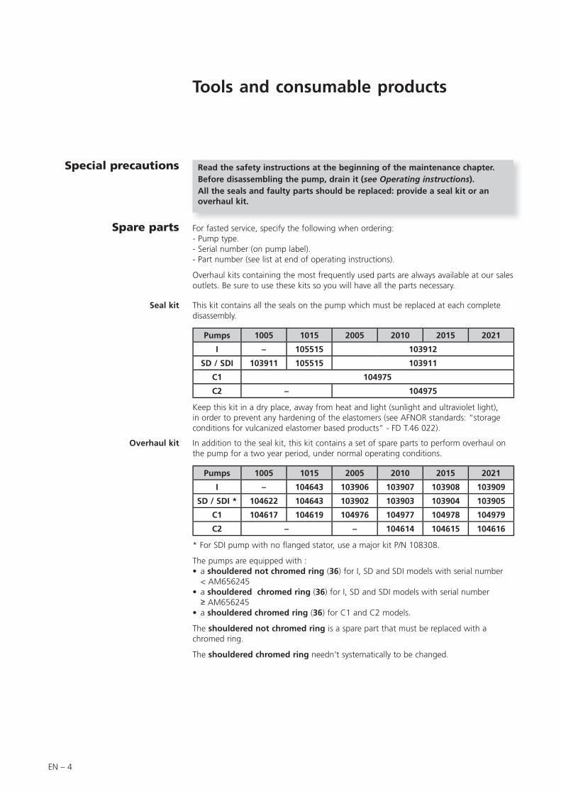
Seal kit This kit contains all the seals on the pump which must be replaced at each complete disassembly.
Pumps 1005 1015 2005 2010 2015 2021
I – 105515 103912
SD / SDI 103911 105515 103911
C1 104975
C2 – 104975
Keep this kit in a dry place, away from heat and light (sunlight and ultraviolet light), in order to prevent any hardening of the elastomers (see AFNOR standards: “storage conditions for vulcanized elastomer based products” - FD T.46 022).
Special precautions Read the safety instructions at the beginning of the maintenance chapter.Before disassembling the pump, drain it (see Operating instructions).All the seals and faulty parts should be replaced: provide a seal kit or an overhaul kit.
Spare parts
In addition to the seal kit, this kit contains a set of spare parts to perform overhaul on the pump for a two year period, under normal operating conditions.
Pumps 1005 1015 2005 2010 2015 2021
I – 104643 103906 103907 103908 103909
SD / SDI * 104622 104643 103902 103903 103904 103905
C1 104617 104619 104976 104977 104978 104979
C2 – – 104614 104615 104616
* For SDI pump with no flanged stator, use a major kit P/N 108308.
The pumps are equipped with :• a shouldered not chromed ring (36) for I, SD and SDI models with serial number
< AM656245• a shouldered chromed ring (36) for I, SD and SDI models with serial number ≥ AM656245
• a shouldered chromed ring (36) for C1 and C2 models.
The shouldered not chromed ring is a spare part that must be replaced with a chromed ring.
The shouldered chromed ring needn’t systematically to be changed.
For fasted service, specify the following when ordering:- Pump type.- Serial number (on pump label).- Part number (see list at end of operating instructions).
Overhaul kits containing the most frequently used parts are always available at our sales outlets. Be sure to use these kits so you will have all the parts necessary.
EN – 5
EN
Main
ten
an
ce
Vane kits for 2-stage pumps This kit contains only vanes and springs in order to maintain several pumps of the same model (see table here after).
Pumps 2005 2010 2015 2021
LP stage vane kit 108417 108396 108397 108398
Vane / Spring (quantity) 20 / 22 20 / 42 20 / 62 20 / 62
HP stage vane kit* 108417 108399 108399 108399
Vane / Spring (quantity) 20 / 22 20 / 22 20 / 22 20 / 22
* except models C1 and C2.
Pumps 2005 2010 2015 2021
Oil vane pump kit** 108407 (10 vanes)
** except models SD and C2.
External shaft seal replacement kit (parts for shaft passage
tightness on motor side)
This kit contains all the parts which must be replaced in the event of a leak on the shaft on the motor side.
Screw kit This kit contains all screws and washers for the range of Pascal’s pump.
Pump models P/N
All pumps 104919
Pump models P/N
All pumps 065612
Spare parts (cont’d)
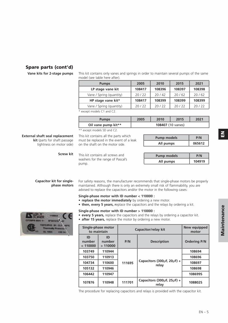
For safety reasons, the manufacturer recommends that single-phase motors be properly maintained. Although there is only an extremely small risk of flammability, you are advised to replace the capacitors and/or the motor in the following cases:
Single-phase motor with ID number < 110000 :• replace the motor immediately by ordering a new motor. • then, every 5 years, replace the capacitors and the relays by ordering a kit.
Single-phase motor with ID number > 110000 :• every 5 years, replace the capacitors and the relays by ordering a capacitor kit.• after 15 years, replace the motor by ordering a new motor.
Single-phase motor to maintain
Capacitor/relay kitNew equipped
motor
ID number
< 110000
ID number
> 110000P/N Description Ordering P/N
103749 110944
111695Capacitors (300μF, 20μF) +
relay
108694
103750 110913 108696
104734 110600 108697
105132 110946 108698
106442 110947 108699S
107876 110948 111701Capacitors (300μF, 25μF) +
relay108802S
The procedure for replacing capacitors and relays is provided with the capacitor kit.
Capacitor kit for single-phase motors
EN – 6
Recommended tools • Two 5.5 x 100 flat screwdrivers
• Thin spanner: 10 mm on face
• Male hexagonal wrench: 2.5 - 3 - 4 - 5 - 12 mm 5
• 12 mm female hexagonal wrench
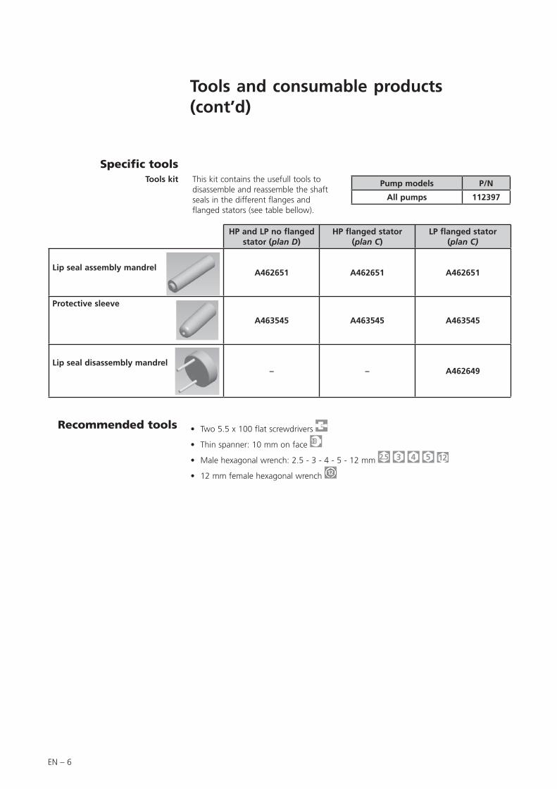
Tools kit This kit contains the usefull tools to disassemble and reassemble the shaft seals in the different flanges and flanged stators (see table bellow).
Pump models P/N
All pumps 112397
Specific tools
HP and LP no flanged stator (plan D)
HP flanged stator(plan C)
LP flanged stator (plan C)
Lip seal assembly mandrel A462651 A462651 A462651
Protective sleeve
A463545 A463545 A463545
Lip seal disassembly mandrel – – A462649
Tools and consumable products (cont’d)
EN – 7
EN
Main
ten
an
ce
Replacement of external shaft seal
In the event of an external oil leak on the pump, it is necessary to change the external shaft seal on the motor side (see page N – 4).
You will need: a front seal replacement kit (see page 5), a screwdriver, a 3, 4 and 5 mm Allen wrench, a lip seal mandrel (see page 6).
Stop the pump and disconnect the power cord motor.
Disconnect the pump from the installation to which it is connected.
If possible, position the pump vertically, with the motor at the top, resting on the front side of the oil case; in this position, it is not necessary to drain the oil case. Otherwise, disassemble the pump in the horizontal position, resting it on its base, after it has been drained (see Operating instructions).
Disconnect the motor by unscrewing the 4 fastening screws, simultaneously and alternately.
Remove the motor vertically.
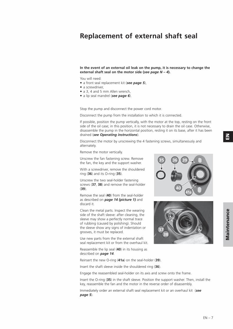
Unscrew the fan fastening screw. Remove the fan, the key and the support washer.
With a screwdriver, remove the shouldered ring (36) and its O-ring (35).
Unscrew the two seal-holder fastening screws (37, 38) and remove the seal-holder (39).
Remove the seal (40) from the seal-holder as described on page 14 (picture 1) and discard it.
Clean the metal parts. Inspect the wearing side of the shaft sleeve: after cleaning, the sleeve may show a perfectly normal trace of rubbing (caused by polishing). Should the sleeve show any signs of indentation or grooves, it must be replaced.
Use new parts from the the external shaft seal replacement kit or from the overhaul kit.
Reassemble the lip seal (40) in its housing as described on page 14.
Reinsert the new O-ring (41a) on the seal-holder (39).
Insert the shaft sleeve inside the shouldered ring (36).
Engage the reassembled seal-holder on its axis and screw onto the frame.
Insert the O-ring (35) in the shaft sleeve. Position the support washer. Then, install the key, reassemble the fan and the motor in the reverse order of disassembly.
Immediately order an external shaft seal replacement kit or an overhaul kit (see page 5).
35 36 39
4041a
3738
EN – 8
Disassembling the pump
Disassembling the fan coupling
(see page N – 2)
Replacing the front seal
Disassembling the gas ballast
except model pump C2(see page N – 2)
Disassembling the motor block
cover
Follow the chronological order of disassembling instructions.See the drawings and their part lists in pages N – 1 to N – 23.
Removing pump fromsystem
The following steps are necessary to protect the pump as far as possible from the effects of corrosion:
• Flush pump with a neutral gas (dry nitrogen) during half an hour to prevent toxic or corrosive gases accumulating in the pump.
• C2 Model: Disconnect the nitrogen lines to the pump.
• Disconnect the pump from the system and seal off the inlet and exhaust ports. Bring the pump to the maintenance area immediately.
• Drain pump (see Operating instructions).
The first phase of disassembly is to disassemble the motor, the second is to disassemble the pumping module.Th fi t h f di bl i t di bl th t th d i t di bl
Do not store a pump in this condition for any length of time: once the neutral gas has dissipated, the inside of the oil case will be in contact with the ambient air laden with water vapor; this may react with the pumped gases to form acids that may corrode the pump even at room temperature.
Study the general precautions listed on Maintenance chapter page 3.
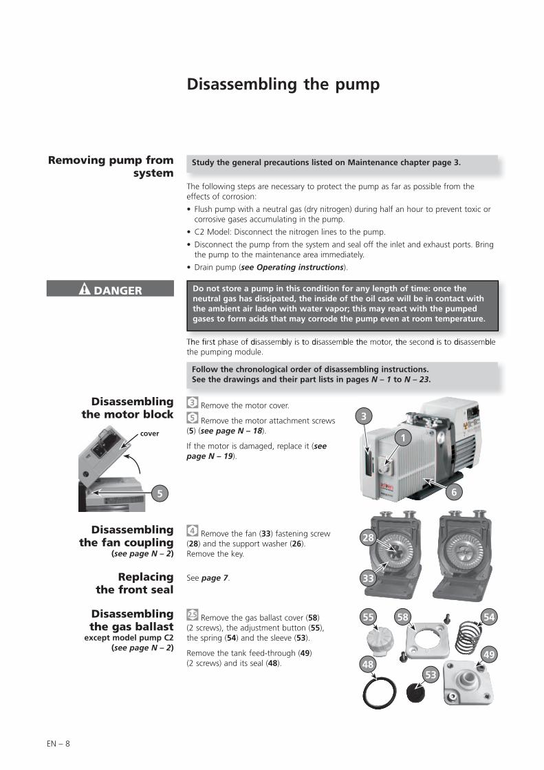
Remove the motor cover.
5 Remove the motor attachment screws (5) (see page N – 18).
If the motor is damaged, replace it (see page N – 19).
1
3
6
Remove the fan (33) fastening screw (28) and the support washer (26).Remove the key.
28
33See page 7.
Remove the gas ballast cover (58)(2 screws), the adjustment button (55), the spring (54) and the sleeve (53).
Remove the tank feed-through (49) (2 screws) and its seal (48).
55 58 54
4948
53
5

EN – 9
EN
Main
ten
an
ce
1 4 4a
5
2 8
Remove the sight glass cover (3).
Remove the plate (1), the ring (4a), the sight glass (4) and the O-ring (5).
Disassembling the oil sight glass
(see page N – 2)
Removing the oil case(see page N – 2)
Disassembling the bubbler (C2 pump)
(see page N – 20)
5 Remove the oil case (6) and its O-ring (11) after removing the 4 fastening screws (9).
Disconnect the nitrogen inlet. Remove the nitrogen inlet and disconnect the coupling (2) without unscrewing the connector (6).
Disconnect the nut (16) which secures the tube on the functional block and pull the bubble (8) to release it from the frame.
Disassembling the exhaust valve cover
(see page N – 6)
5 Remove the screws (4) (13) (15) and the cover(s) (6) (17), the exhaust valves (2) (11) and their springs (3) (12).
4 13
6 17
15
Disassembling the sniffer pipe
(SDI model)(see page N – 10)
5 Remove the screw (41) and its washer.
Insert a flat screwdriver near to the stator connector, and use it as lever arm to remove the sniffer pipe (38) from the stator. Then, pull on the other end of the pipe to remove it from the housing.
41
38
EN – 10
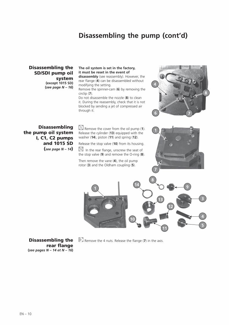
5 Remove the cover from the oil pump (1). Release the cylinder (13) equipped with the washer (14), piston (11) and spring (12).
Release the stop valve (10) from its housing.
In the rear flange, unscrew the seat of the stop valve (9) and remove the O-ring (8).
Then remove the vane (4), the oil pump rotor (3) and the Oldham coupling (5).
Disassembling the pump oil system
I, C1, C2 pumps and 1015 SD (see page N – 14)
Remove the 4 nuts. Release the flange (7) in the axis.Disassembling therear flange
(see pages N – 14 et N – 16)
114
8
9
3
4
5
12
13
10
11
1
7
Disassembling the SD/SDI pump oil
system (except 1015 SD)(see page N – 16)
The oil system is set in the factory, it must be reset in the event of disassembly (see reassembly). However, the rear flange (4) can be disassembled without modifying the setting.Remove the spinner-cam (6) by removing the circlip (7).Do not disassemble the nozzle (8) to clean it. During the reassembly, check that it is not blocked by sending a jet of compressed air through it.
4
6 7
8
Disassembling the pump (cont’d)
EN – 11
EN
Main
ten
an
ce
Disassembling the pumping module
with flanged stator(see N – 10)
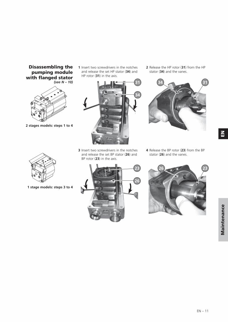
1 Insert two screwdrivers in the notches and release the set HP stator (34) and HP rotor (31) in the axis.
2 Release the HP rotor (31) from the HP stator (34) and the vanes.
3 Insert two screwdrivers in the notches and release the set BP stator (26) and BP rotor (23) in the axis.
4 Release the BP rotor (23) from the BP stator (26) and the vanes.
31
34
34 31
232623
26
2 stages models: steps 1 to 4
1 stage models: steps 3 to 4
EN – 12
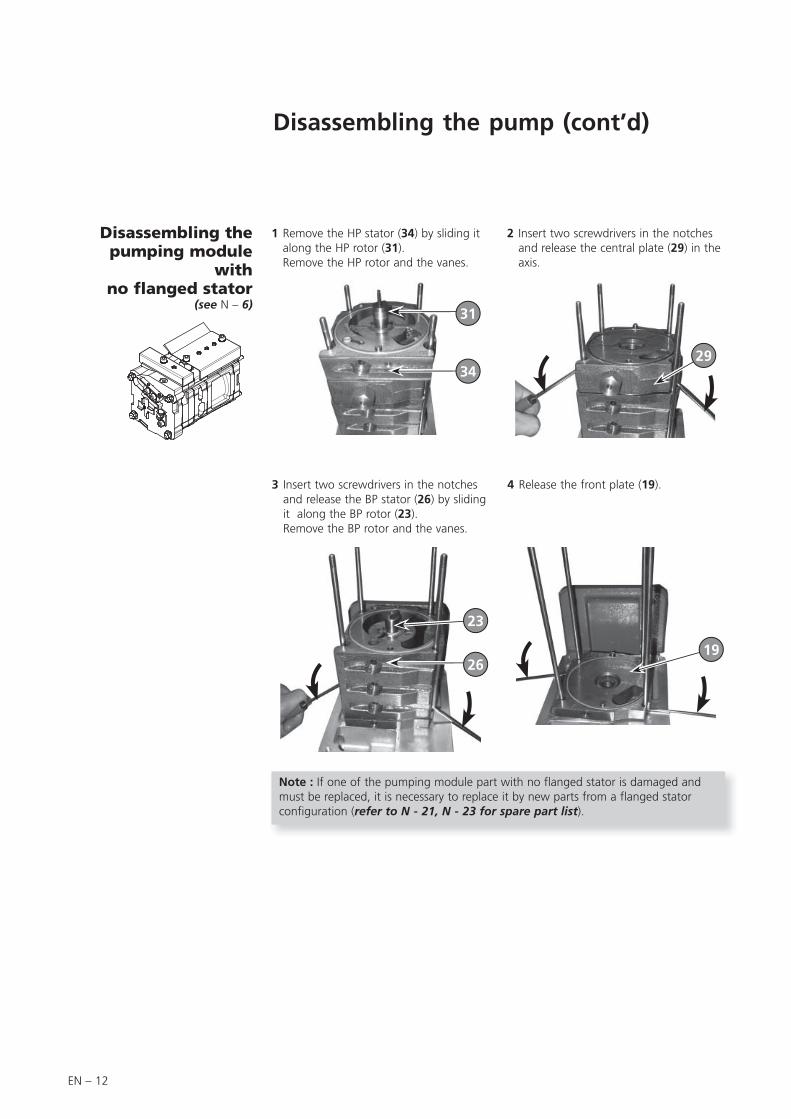
Disassembling the pumping module
with no flanged stator
(see N – 6)
1 Remove the HP stator (34) by sliding it along the HP rotor (31).Remove the HP rotor and the vanes.
2 Insert two screwdrivers in the notches and release the central plate (29) in the axis.
3 Insert two screwdrivers in the notches and release the BP stator (26) by sliding it along the BP rotor (23).Remove the BP rotor and the vanes.
4 Release the front plate (19).
31
34
23
26
29
19
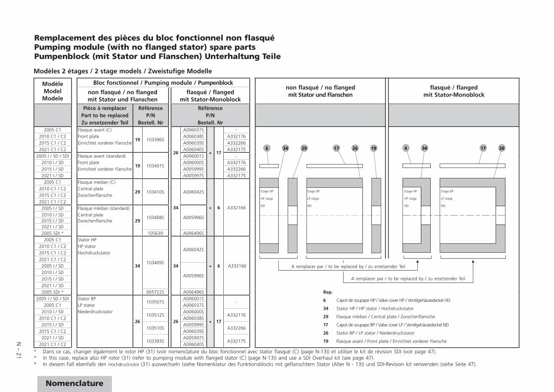
Note : If one of the pumping module part with no flanged stator is damaged and must be replaced, it is necessary to replace it by new parts from a flanged stator configuration (refer to N - 21, N - 23 for spare part list).
Disassembling the pump (cont’d)
EN – 13
EN
Main
ten
an
ce
Cleaning components
Cleaning metal components
Cleaning the oil level sight glass
I, SD, SDI, C2 series pumps
Solvents are required to clean components.
Standard precautions should be taken in compliance with the manufacturer's instructions.
After use in mineral or synthetic oil, clean the metal components with a mineral products based solvent such as AXAREL(1) , CARECLEAN(2), PREMACLEAN(3), NAPHTESOL(4). Proceed as follows:• Clean when cold or hot (max. 45°C) by dipping or using a cloth• Vacuum dry in a ventilated oven• The component must be cleaned a second time with alcohol.
After use in (perfluorinate) synthetic oil, clean the metal components in a solvent such as GALDEN S 90™(5) and proceed as follows:• Clean when cold by dipping or using a cloth• Dry the components in the air or with compressed air
After use in (non-perfluorinate) synthetic or mineral oil, clean the metal components with a solvent such as alcohol and proceed as follows:• Clean when cold by dipping or using a cloth• Dry the components in the air• Industrial washing solutions can also be used. The cleaning operation should be
followed by vacuum drying.
When cleaning this plastic sight glass, avoid contact with alcohol or alcohol-based washing solutions. Clean the component with a solvent, but do not steep it, and rinse it immediately.
The sight glass of these pumps is made of glass: it can be cleaned with common used solvents.
(1) DUPONT DE NEMOURS registered trademark(2) CASTROL registered trademark(3) DOW registered trademark(4) Nippon Oil Corporation registered trademark(5) MONTEDISON registered trademark
C1 series pumps
EN – 14
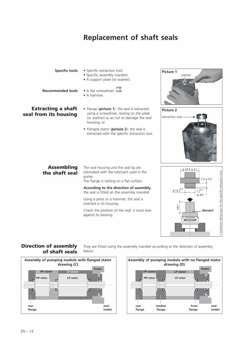
Replacement of shaft seals
Recommended tools
• Specific extraction tool.• Specific assembly mandrel.• A support plate (or washer).
• A flat screwdriver .• A hammer.
• Flange (picture 1): the seal is extracted using a screwdriver, resting on the plate (or washer) so as not to damage the seal housing, or
• Flanged stator (picture 2): the seal is extracted with the specific extraction tool.
The seal housing and the seal lip are lubricated with the lubricant used in the pump.The flange is resting on a flat surface.
According to the direction of assembly, the seal is fitted on the assembly mandrel.
Using a press or a hammer, the seal is inserted in its housing.
Check the position of the seal: it must lean against its bearing.
They are fitted using the assembly mandrel according to the direction of assembly below:
Direction of assemblyof shaft seals
Assembling the shaft seal
Extracting a shaft seal from its housing
ø 24.5 ± 0.1
5.5 ± 0.210
5*
ø 14+0.20 1
at 45°
+0.20
Picture 1
Picture 2
Mandrel
* m
inim
um d
imen
sion
for
the
spe
cific
ext
ract
ion
tool
.
Specific tools
HP rotor
frame
rear fl ange
front fl ange
seal-holder
medianfl ange
Assembly of pumping module with no flanged stator drawing (D)
HP stator
LP rotor
LP stator
washer
extraction tool
HP rotor
frame
rear fl ange
seal-holder
HP stator
LP rotor
LP stator
Assembly of pumping module with flanged stator drawing (C)
EN – 15
EN
Main
ten
an
ce
Reassembling the pump
• All surfaces in contact are coated with oil (rotors, vanes...).• Check that the lubrication holes are not blocked.• Observe the nominal clamping torques for the reassembly of the functional
block (see chapter “Nomenclature”).• Rest the frame (42) on a flat surface in order to raise the pump.
Component preparation
Reassembling the pumping module
with flanged stator(see page N – 10)
1 Place the BP stator (26) on the frame (42).If there is no centering pin, align the top of the stator with the exhaust notch in the housing.
2 For not damage the shaft seal, use protective sleeve on the rotor axis (or wrap end of shaft with adhesive tape) and oil it.
3 Slide the BP rotor (23) equipped with its vanes and springs (rounded edges facing outwards) in the BP stator (26). Remove the protective sleeve
4 Place the HP stator (34) on the BP stator (26).
5 Slide the HP rotor (31) equipped with its vanes and springs (rounded edges facing outwards) in the HP stator (34).
6 Place the rear flange (7) on the HP stator (34).
Sleeve
26
23
31
34
7
26
2 stages models: steps 1 to à 6
1 stage models: steps 1, 2, 3 and 6
EN – 16
Reassembling the pumping module with no flanged
stator(see page N – 6)
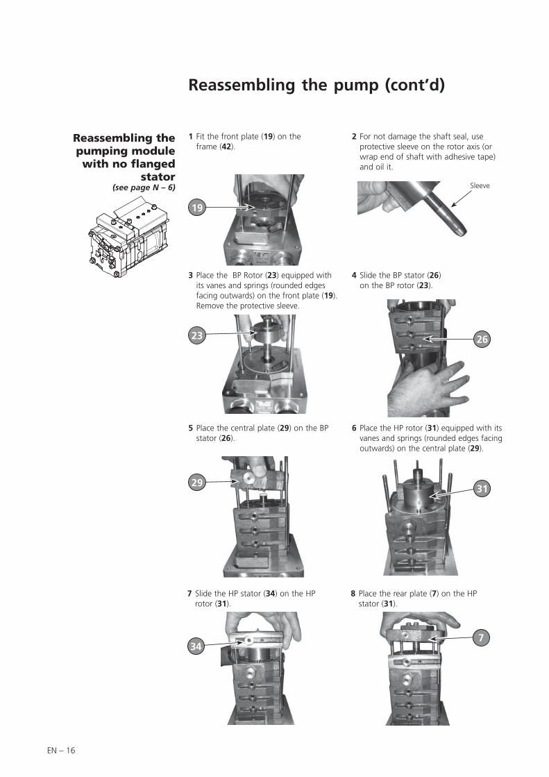
1 Fit the front plate (19) on the frame (42).
2 For not damage the shaft seal, use protective sleeve on the rotor axis (or wrap end of shaft with adhesive tape) and oil it.
3 Place the BP Rotor (23) equipped with its vanes and springs (rounded edges facing outwards) on the front plate (19). Remove the protective sleeve.
4 Slide the BP stator (26) on the BP rotor (23).
5 Place the central plate (29) on the BP stator (26).
6 Place the HP rotor (31) equipped with its vanes and springs (rounded edges facing outwards) on the central plate (29).
Sleeve
2931
23 26
19
7 Slide the HP stator (34) on the HP rotor (31).
8 Place the rear plate (7) on the HP stator (31).
347
Reassembling the pump (cont’d)
EN – 17
EN
Main
ten
an
ce
C1 series pump: The sight glass is made of glass: gradually tighten the two attachment screws in alternation to avoid placing the sight glass under stress.
Reassembling the oil casing
(see page N – 6)
Reassembling the oil level sight glass
(see page N – 2)
Fit the oil casing (6) equipped with its o-ring (11) on the frame (42).Tighten it with screw (9) and washers (10) ( after making sure that the seal is positioned in its seal groove).
Place the o-ring (5) in its groove and fit the sight glass (4), the flat ring (4a) (according to the model), the oil sight glass cover (3) and tighten with screws (2). Comply with the recommended tightening torque.
Reasembling the gas ballast
(see page N – 2)
Position the oil case feed-through (49) equipped with its o-ring (48) in its housing by centering it on the gas ballast tube (46). Assemble using the screws (52).
Equip the adjustment knob (55) with the sleeve (53) and the spring (54). Position the assembly in the cover (58) and secure on the oil case feed-through (49) with screws (57).
a
d
c
b
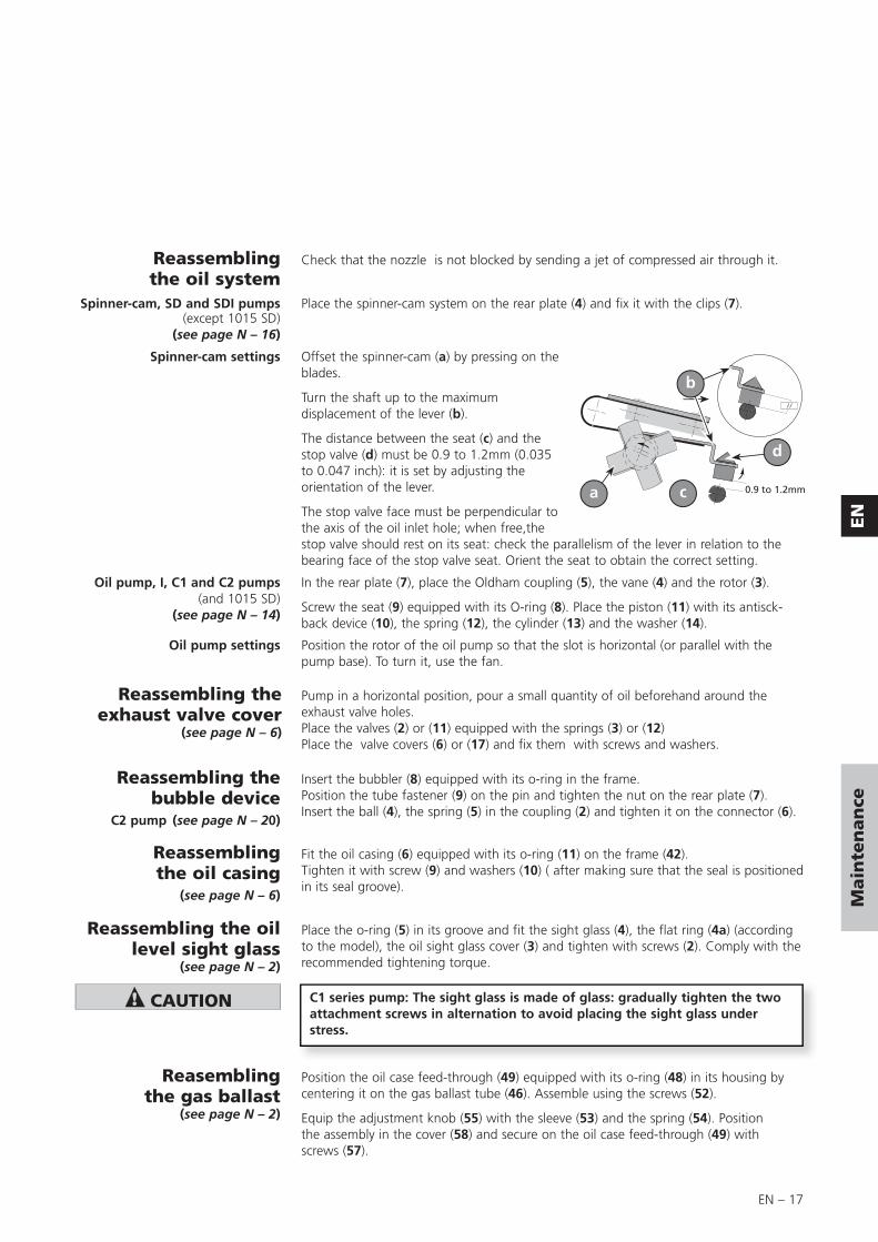
Check that the nozzle is not blocked by sending a jet of compressed air through it.Reassembling the oil system
Reassembling the exhaust valve cover
(see page N – 6)
Reassembling the bubble device
C2 pump (see page N – 20)
Spinner-cam, SD and SDI pumps (except 1015 SD)
(see page N – 16)
Spinner-cam settings
Oil pump, I, C1 and C2 pumps (and 1015 SD)
(see page N – 14)
Oil pump settings
Place the spinner-cam system on the rear plate (4) and fix it with the clips (7).
Offset the spinner-cam (a) by pressing on the blades.
Turn the shaft up to the maximum displacement of the lever (b).
The distance between the seat (c) and the stop valve (d) must be 0.9 to 1.2mm (0.035 to 0.047 inch): it is set by adjusting the orientation of the lever.
The stop valve face must be perpendicular to the axis of the oil inlet hole; when free,the stop valve should rest on its seat: check the parallelism of the lever in relation to the bearing face of the stop valve seat. Orient the seat to obtain the correct setting.
In the rear plate (7), place the Oldham coupling (5), the vane (4) and the rotor (3).
Screw the seat (9) equipped with its O-ring (8). Place the piston (11) with its antisck-back device (10), the spring (12), the cylinder (13) and the washer (14).
Position the rotor of the oil pump so that the slot is horizontal (or parallel with the pump base). To turn it, use the fan.
Pump in a horizontal position, pour a small quantity of oil beforehand around the exhaust valve holes.Place the valves (2) or (11) equipped with the springs (3) or (12)Place the valve covers (6) or (17) and fix them with screws and washers.
Insert the bubbler (8) equipped with its o-ring in the frame.Position the tube fastener (9) on the pin and tighten the nut on the rear plate (7).Insert the ball (4), the spring (5) in the coupling (2) and tighten it on the connector (6).
EN – 18
Reassembling the seal-holder
(see page N – 2)
Reassembling the fan and the motor side
components(see page N – 2)
(See page 7).
Fill with oil
Fit the shaft key (22) (N – 10) on HP rotor.Fit the coupling fan (33) and secure it with the screw (28) and washer (26).Fit the drive key on the motor shaft. Install the motor coupling (3) (N – 18) down to the stop on the motor shaft and secure it with the screw (2) (N – 18).Install the plastic coupling (4) (N – 18) on the motor coupling (3) (N – 18).Fit the motor on the frame and secure with the 4 mounting bolts (5) (N – 18).
After reassembling, fill the pump with oil before start-up the pump (see Operating instructions).
Reassembling of the pumping pipe
(model SDI)
Position one the end of the pipe (38) into the housing hole designed for this purpose and the other end on the stator (34).
Do not forget to install o-rings (39) and (40) after having checked their status (no cuts).
Reassembling the pump (cont’d)
EN – 19
EN
Main
ten
an
ce
Service
On-Site maintenance for many products Overhaul / repair in the nearby Service Location Fast replacement with refurbished exchange products in mint condition Advice on the most cost-effi cient and quickest solution
Detailed information, addresses and forms at: www.pfeiffer-vacuum.com (Service).
The following general recommendations will ensure a fast, smooth servicing process: Fill out the «Service Request/Product return» form and send it to your local Pfeiffer Vacuum Service contact.
Include the confirmation on the service request from Pfeiffer Vacuum with your shipment.
Fill out the declaration of contamination and include it in the shipment (mandatory!). The Declaration of contamination is valid for any product/device including a part exposed to vacuum.
Dismantle all accessories and keep them.
Close all the ports flange openings by using the original protective covers or metallic airtight blank flanges for contaminated devices.
If possible, send pump or unit in its original packaging.
No devices will be accepted if they are contaminated with micro-biological, explosive or radioactive substances. “Hazardous substances” are substances and compounds in accordance with the hazardous goods regulations (current version).
Neutralize the pump by flushing it with nitrogen or dry air.
Close all openings airtight.
Seal the pump or device in suitable protective film.
Return the pump/device only in a suitable and sturdy transport container and send it in while following applicable transport conditions.
Pump or device returned without declaration of contamination form fully completed and/or non-secured in a suitable packaging, will be decontaminated and/or returned at the shipper’s expense.
The factory operating parameters are always preset with exchange or repaired devices. If you use specific parameters for your application, you have to set these again.
All service orders are carried out exclusively according to our general terms and conditions for the repair and maintenance, available in our website.
Pfeiffer Vacuum offers first-class
customer service!
Overhaul and repair in the Pfeiffer
Vacuum Service Center
Sending of contaminated pumps
or devices
Exchange or repaired devices
Service orders

N – 1
Nomenclature
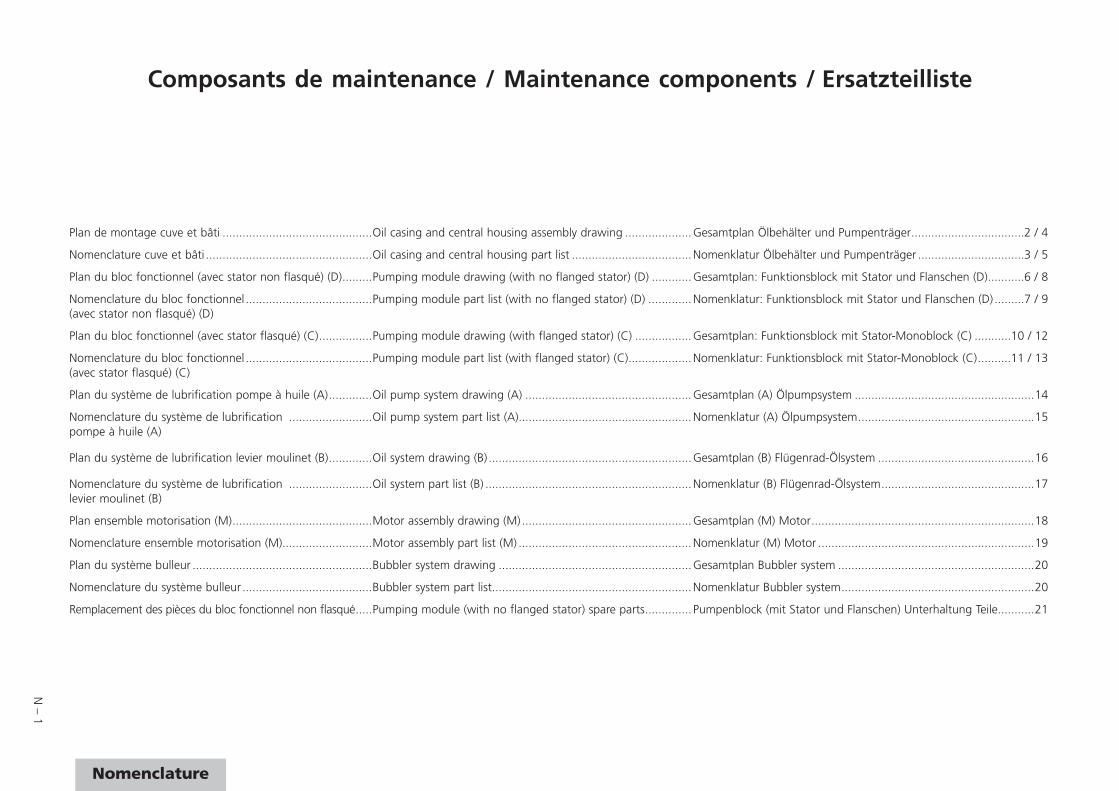
Composants de maintenance / Maintenance components / Ersatzteilliste
Plan de montage cuve et bâti .............................................Oil casing and central housing assembly drawing ....................Gesamtplan Ölbehälter und Pumpenträger ..................................2 / 4
Nomenclature cuve et bâti ..................................................Oil casing and central housing part list ....................................Nomenklatur Ölbehälter und Pumpenträger ................................3 / 5
Plan du bloc fonctionnel (avec stator non flasqué) (D) .........Pumping module drawing (with no flanged stator) (D) ............Gesamtplan: Funktionsblock mit Stator und Flanschen (D) ...........6 / 8
Nomenclature du bloc fonctionnel ......................................Pumping module part list (with no flanged stator) (D) .............Nomenklatur: Funktionsblock mit Stator und Flanschen (D) .........7 / 9(avec stator non flasqué) (D)
Plan du bloc fonctionnel (avec stator flasqué) (C) ................Pumping module drawing (with flanged stator) (C) .................Gesamtplan: Funktionsblock mit Stator-Monoblock (C) ...........10 / 12
Nomenclature du bloc fonctionnel ......................................Pumping module part list (with flanged stator) (C) ...................Nomenklatur: Funktionsblock mit Stator-Monoblock (C) ..........11 / 13(avec stator flasqué) (C)
Plan du système de lubrification pompe à huile (A) .............Oil pump system drawing (A) ..................................................Gesamtplan (A) Ölpumpsystem ......................................................14
Nomenclature du système de lubrification .........................Oil pump system part list (A) ....................................................Nomenklatur (A) Ölpumpsystem .....................................................15pompe à huile (A)
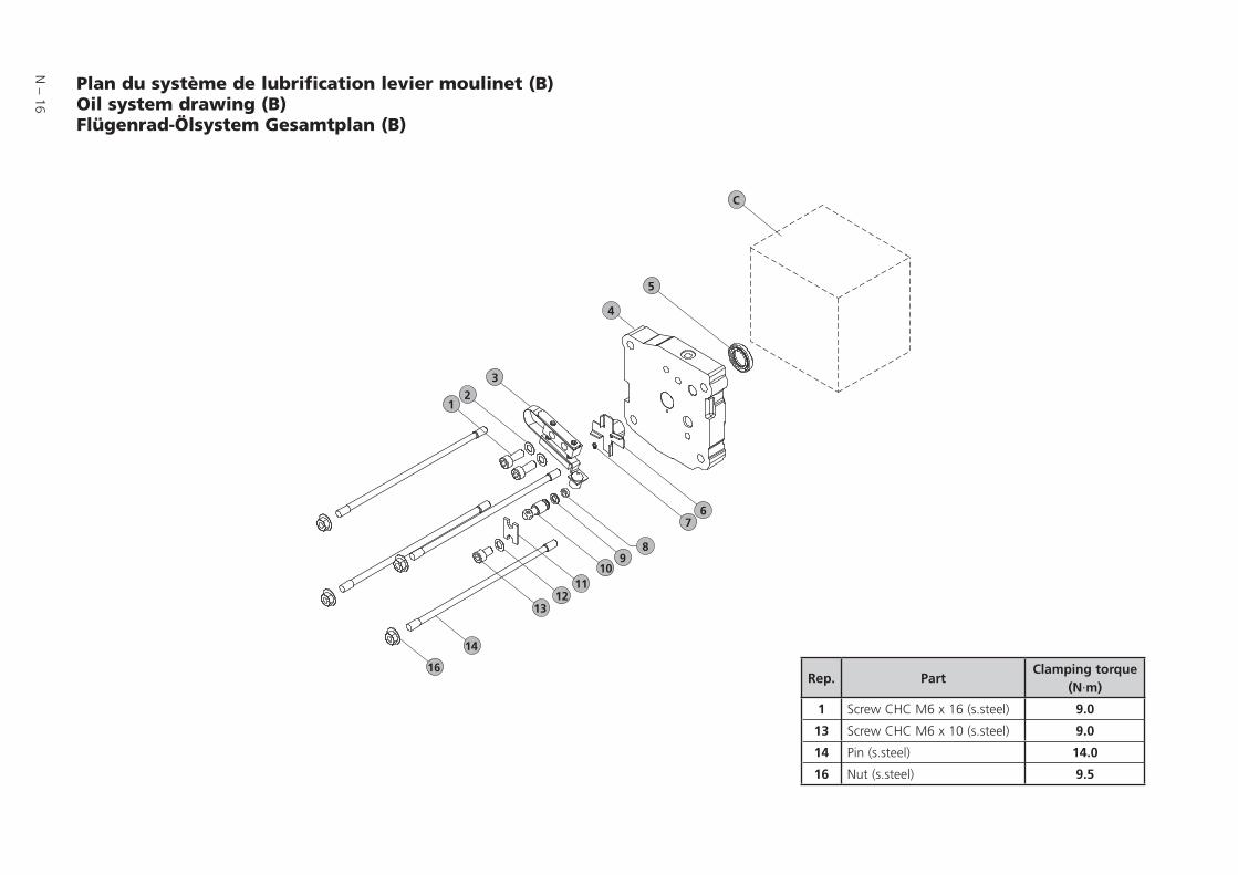
Plan du système de lubrification levier moulinet (B) .............Oil system drawing (B) .............................................................Gesamtplan (B) Flügenrad-Ölsystem ...............................................16
Nomenclature du système de lubrification .........................Oil system part list (B) ..............................................................Nomenklatur (B) Flügenrad-Ölsystem ..............................................17levier moulinet (B)
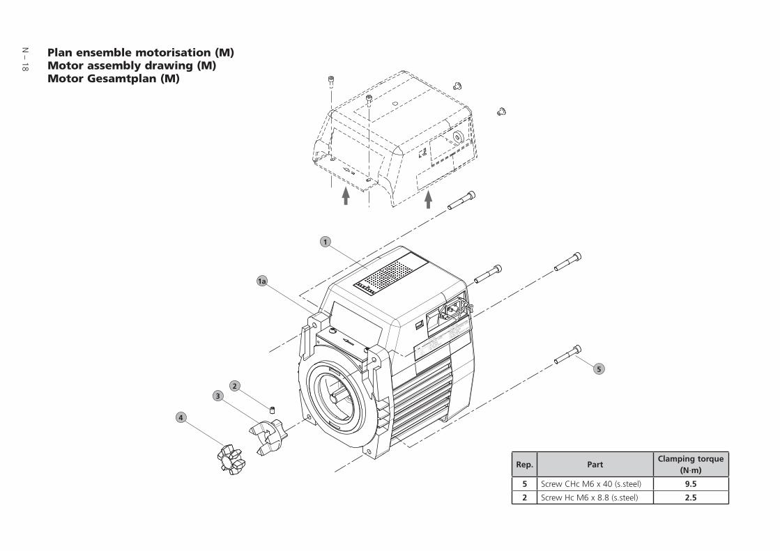
Plan ensemble motorisation (M) ..........................................Motor assembly drawing (M) ...................................................Gesamtplan (M) Motor ...................................................................18
Nomenclature ensemble motorisation (M) ...........................Motor assembly part list (M) ....................................................Nomenklatur (M) Motor .................................................................19
Plan du système bulleur ......................................................Bubbler system drawing ..........................................................Gesamtplan Bubbler system ...........................................................20
Nomenclature du système bulleur .......................................Bubbler system part list ............................................................Nomenklatur Bubbler system ..........................................................20
Remplacement des pièces du bloc fonctionnel non flasqué .....Pumping module (with no flanged stator) spare parts .............. Pumpenblock (mit Stator und Flanschen) Unterhaltung Teile ...........21
N – 2
1
57
58
59
5554
5349
4847
4645
43
43
43a
43b
43a
59a
43c
42
4141a
4039
3837
3635
3433
44
52
2
3
44a
5
67
8
11
1213
1415
1617
17a
23
18
19
20
8a
21
22
2826
910
C
M
Bor
Dor
A
1015I
1015I
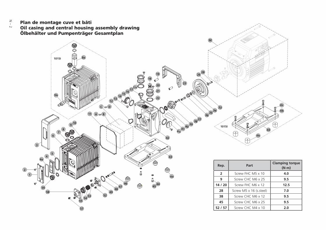
Plan de montage cuve et bâtiOil casing and central housing assembly drawing Ölbehälter und Pumpenträger Gesamtplan
Rep. PartClamping torque
(N·m)
2 Screw FHC M5 x 10 4.0
9 Screw CHC M6 x 25 9.5
14 / 20 Screw FHC M6 x 12 12.5
28 Screw M5 x 16 (s.steel) 7.0
38 Screw CHC M6 x 12 9.5
45 Screw CHC M6 x 25 9.5
52 / 57 Screw CHC M4 x 10 2.0
N – 3
Nomenclature
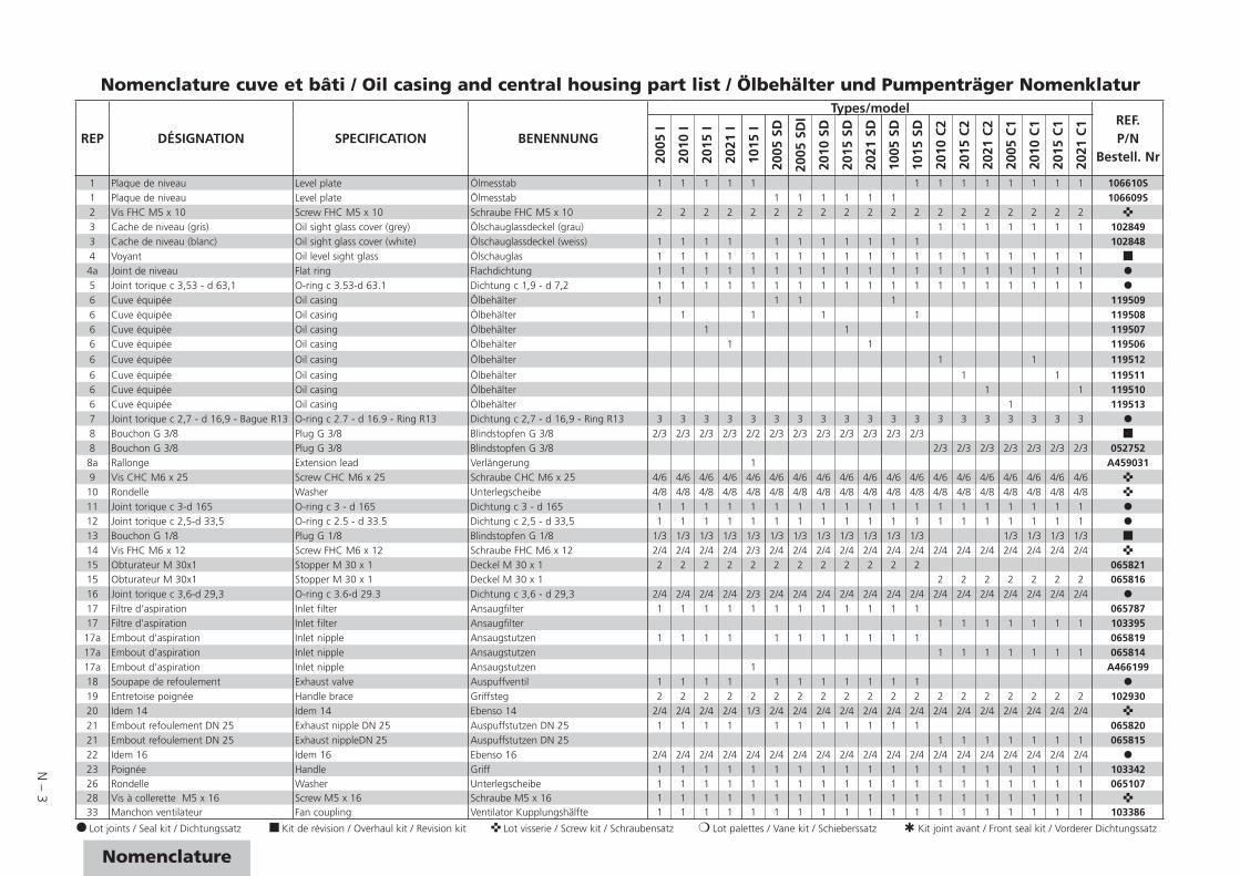
Nomenclature cuve et bâti / Oil casing and central housing part list / Ölbehälter und Pumpenträger Nomenklatur
REP DÉSIGNATION SPECIFICATION BENENNUNG
Types/modelREF.P/N
Bestell. Nr2005
I
2010
I
2015
I
2021
I
1015
I
2005
SD
2005
SD
I
2010
SD
2015
SD
2021
SD
1005
SD
1015
SD
2010
C2
2015
C2
2021
C2
2005
C1
2010
C1
2015
C1
2021
C1
1 Plaque de niveau Level plate Ölmesstab 1 1 1 1 1 1 1 1 1 1 1 1 1 106610S1 Plaque de niveau Level plate Ölmesstab 1 1 1 1 1 1 106609S2 Vis FHC M5 x 10 Screw FHC M5 x 10 Schraube FHC M5 x 10 2 2 2 2 2 2 2 2 2 2 2 2 2 2 2 2 2 2 2 3 Cache de niveau (gris) Oil sight glass cover (grey) Ölschauglassdeckel (grau) 1 1 1 1 1 1 1 1028493 Cache de niveau (blanc) Oil sight glass cover (white) Ölschauglassdeckel (weiss) 1 1 1 1 1 1 1 1 1 1 1 1028484 Voyant Oil level sight glass Ölschauglas 1 1 1 1 1 1 1 1 1 1 1 1 1 1 1 1 1 1 1 4a Joint de niveau Flat ring Flachdichtung 1 1 1 1 1 1 1 1 1 1 1 1 1 1 1 1 1 1 15 Joint torique c 3,53 - d 63,1 O-ring c 3.53-d 63.1 Dichtung c 1,9 - d 7,2 1 1 1 1 1 1 1 1 1 1 1 1 1 1 1 1 1 1 16 Cuve équipée Oil casing Ölbehälter 1 1 1 1 1195096 Cuve équipée Oil casing Ölbehälter 1 1 1 1 1195086 Cuve équipée Oil casing Ölbehälter 1 1 1195076 Cuve équipée Oil casing Ölbehälter 1 1 119506
6 Cuve équipée Oil casing Ölbehälter 1 1 119512
6 Cuve équipée Oil casing Ölbehälter 1 1 1195116 Cuve équipée Oil casing Ölbehälter 1 1 1195106 Cuve équipée Oil casing Ölbehälter 1 1195137 Joint torique c 2,7 - d 16,9 - Bague R13 O-ring c 2.7 - d 16.9 - Ring R13 Dichtung c 2,7 - d 16,9 - Ring R13 3 3 3 3 3 3 3 3 3 3 3 3 3 3 3 3 3 3 38 Bouchon G 3/8 Plug G 3/8 Blindstopfen G 3/8 2/3 2/3 2/3 2/3 2/2 2/3 2/3 2/3 2/3 2/3 2/3 2/3 8 Bouchon G 3/8 Plug G 3/8 Blindstopfen G 3/8 2/3 2/3 2/3 2/3 2/3 2/3 2/3 0527528a Rallonge Extension lead Verlängerung 1 A4590319 Vis CHC M6 x 25 Screw CHC M6 x 25 Schraube CHC M6 x 25 4/6 4/6 4/6 4/6 4/6 4/6 4/6 4/6 4/6 4/6 4/6 4/6 4/6 4/6 4/6 4/6 4/6 4/6 4/6
10 Rondelle Washer Unterlegscheibe 4/8 4/8 4/8 4/8 4/8 4/8 4/8 4/8 4/8 4/8 4/8 4/8 4/8 4/8 4/8 4/8 4/8 4/8 4/8 11 Joint torique c 3-d 165 O-ring c 3 - d 165 Dichtung c 3 - d 165 1 1 1 1 1 1 1 1 1 1 1 1 1 1 1 1 1 1 112 Joint torique c 2,5-d 33,5 O-ring c 2.5 - d 33.5 Dichtung c 2,5 - d 33,5 1 1 1 1 1 1 1 1 1 1 1 1 1 1 1 1 1 1 113 Bouchon G 1/8 Plug G 1/8 Blindstopfen G 1/8 1/3 1/3 1/3 1/3 1/3 1/3 1/3 1/3 1/3 1/3 1/3 1/3 1/3 1/3 1/3 1/3 14 Vis FHC M6 x 12 Screw FHC M6 x 12 Schraube FHC M6 x 12 2/4 2/4 2/4 2/4 2/3 2/4 2/4 2/4 2/4 2/4 2/4 2/4 2/4 2/4 2/4 2/4 2/4 2/4 2/4 15 Obturateur M 30x1 Stopper M 30 x 1 Deckel M 30 x 1 2 2 2 2 2 2 2 2 2 2 2 2 06582115 Obturateur M 30x1 Stopper M 30 x 1 Deckel M 30 x 1 2 2 2 2 2 2 2 06581616 Joint torique c 3,6-d 29,3 O-ring c 3.6-d 29.3 Dichtung c 3,6 - d 29,3 2/4 2/4 2/4 2/4 2/3 2/4 2/4 2/4 2/4 2/4 2/4 2/4 2/4 2/4 2/4 2/4 2/4 2/4 2/417 Filtre d’aspiration Inlet filter Ansaugfilter 1 1 1 1 1 1 1 1 1 1 1 1 06578717 Filtre d’aspiration Inlet filter Ansaugfilter 1 1 1 1 1 1 1 10339517a Embout d’aspiration Inlet nipple Ansaugstutzen 1 1 1 1 1 1 1 1 1 1 1 06581917a Embout d’aspiration Inlet nipple Ansaugstutzen 1 1 1 1 1 1 1 06581417a Embout d’aspiration Inlet nipple Ansaugstutzen 1 A46619918 Soupape de refoulement Exhaust valve Auspuffventil 1 1 1 1 1 1 1 1 1 1 119 Entretoise poignée Handle brace Griffsteg 2 2 2 2 2 2 2 2 2 2 2 2 2 2 2 2 2 2 2 10293020 Idem 14 Idem 14 Ebenso 14 2/4 2/4 2/4 2/4 1/3 2/4 2/4 2/4 2/4 2/4 2/4 2/4 2/4 2/4 2/4 2/4 2/4 2/4 2/4 21 Embout refoulement DN 25 Exhaust nipple DN 25 Auspuffstutzen DN 25 1 1 1 1 1 1 1 1 1 1 1 06582021 Embout refoulement DN 25 Exhaust nippleDN 25 Auspuffstutzen DN 25 1 1 1 1 1 1 1 06581522 Idem 16 Idem 16 Ebenso 16 2/4 2/4 2/4 2/4 2/4 2/4 2/4 2/4 2/4 2/4 2/4 2/4 2/4 2/4 2/4 2/4 2/4 2/4 2/423 Poignée Handle Griff 1 1 1 1 1 1 1 1 1 1 1 1 1 1 1 1 1 1 1 10334226 Rondelle Washer Unterlegscheibe 1 1 1 1 1 1 1 1 1 1 1 1 1 1 1 1 1 1 1 06510728 Vis à collerette M5 x 16 Screw M5 x 16 Schraube M5 x 16 1 1 1 1 1 1 1 1 1 1 1 1 1 1 1 1 1 1 1 33 Manchon ventilateur Fan coupling Ventilator Kupplungshälfte 1 1 1 1 1 1 1 1 1 1 1 1 1 1 1 1 1 1 1 103386
Lot joints / Seal kit / Dichtungssatz Kit de révision / Overhaul kit / Revision kit Lot visserie / Screw kit / Schraubensatz Lot palettes / Vane kit / Schieberssatz Kit joint avant / Front seal kit / Vorderer Dichtungssatz
N – 4
1
57
58
59
5554
5349
4847
4645
43
43
43a
43b
43a
59a
43c
42
4141a
4039
3837
3635
3433
44
52
2
3
44a
5
67
8
11
1213
1415
1617
17a
23
18
19
20
8a
21
22
2826
910
C
M
Bor
Dor
A
1015I
1015I
Rep. PartClamping torque
(N·m)
2 Screw FHC M5 x 10 4.0
9 Screw CHC M6 x 25 9.5
14 / 20 Screw FHC M6 x 12 12.5
28 Screw M5 x 16 (s.steel) 7.0
38 Screw CHC M6 x 12 9.5
45 Screw CHC M6 x 25 9.5
52 / 57 Screw CHC M4 x 10 2.0
Plan de montage cuve et bâtiOil casing and central housing assembly drawing Ölbehälter und Pumpenträger Gesamtplan
N – 5
Nomenclature
REP DÉSIGNATION SPECIFICATION BENENNUNG
Types/modelREF.P/N
Bestell. Nr2005
I
2010
I
2015
I
2021
I
1015
I
2005
SD
2005
SD
I
2010
SD
2015
SD
2021
SD
1005
SD
1015
SD
2010
C2
2015
C2
2021
C2
2005
C1
2010
C1
2015
C1
2021
C1
34 Rondelle d’appui Washer Unterlegscheibe 1 1 1 1 1 1 1 1 1 1 1 1 1 1 1 1 1 1 1 06584735 Joint torique c 2,7 - d 12,1 Bague R1O O-ring c 2.7 - d 12.1 - Ring R1O Dichtung c 2,7 - d 12,1 - Ring R1O 1 1 1 1 1 1 1 1 1 1 1 1 1 1 1 1 1 1 1 36 Bague épaulée Shouldered ring Abnutzungring 1 1 1 1 1 1 1 1 1 1 1 1 1 1 1 1 1 1 1 06582337 Idem 10 Idem 10 Ebenso 10 2/8 2/8 2/8 2/8 2/8 2/8 2/8 2/8 2/8 2/8 2/8 2/8 2/8 2/8 2/8 2/8 2/8 2/8 2/838 Vis CHC M6 x 12 Screw CHC M6 x 12 Schraube CHC M6 x 12 2 2 2 2 2 2 2 2 2 2 2 2 2 2 2 2 2 2 239 Porte joint Seal holder Lippendichtung-sockel 1 1 1 1 1 1 1 1 1 1 1 1 1 1 1 1 1 1 1 A33366040 Joint à lèvre 15 x 25,5 x 4,6 FMP81 Shaft seal 15 x 25.5 x 4.6 FMP81 Lippendichtung 15 x 25,5 x 4,6 FMP81 1 1 1 1 1 1 1 1 1 1 1 1 1 1 1 1 1 1 1 41 Feutre Felt Filz 1 1 1 1 1 1 1 1 1 1 1 1 1 1 1 1 1 1 1 41a Joint torique c 3,6-d 34,1 O-ring c 3.6-d 34.1 Dichtung c 3,6 - d 34,1 1 1 1 1 1 1 1 1 1 1 1 1 1 1 1 1 1 1 1 42 Bâti équipé* Equipped central housing* Pumpenträger einrichtet* 1 1 1 1 1 1 103384S42 Bâti équipé* Equipped central housing* Pumpenträger einrichtet* 1 1 1 1 1 103385S42 Bâti équipé* Equipped central housing* Pumpenträger einrichtet* 1 105834S42 Bâti équipé* Equipped central housing* Pumpenträger einrichtet* 1 1 1 1 1 1 1 105832S43 Socle Base Fuss 1 1 1 1 1 1 1 1 1 1 1 1 1 1 1 1 1 1 10871243 Socle Base Fuss 1 107134S43a Amortisseur Shock mount Schwingunsdämpferm 4/4 4/4 4/4 4/4 4/4 4/4 4/4 4/4 4/4 4/4 4/4 4/4 4/4 4/4 4/4 4/4 4/4 4/4 06579043a Amortisseur Shock mount Schwingunsdämpferm 4/4 08269143b Rondelle Washer Unterlegscheibe 4/443c Vis CHC M6 x 12 Screw CHC M6 x 12 Schraube CHC M6 x 12 4/444 Idem 10 Idem 10 Ebenso 10 2/8 2/8 2/8 2/8 2/8 2/8 2/8 2/8 2/8 2/8 2/8 2/8 2/8 2/8 2/8 2/8 2/8 2/845 Idem 9 Idem 9 Ebenso 9 2/6 2/6 2/6 2/6 2/6 2/6 2/6 2/6 2/6 2/6 2/6 2/6 2/6 2/6 2/6 2/6 2/6 2/646 Tube lest d’air Gas ballast tube Gasballasttrohr 1 1 1 1 1 1 1 1 1 1 1 1 1 1 1 1 10463146 Tube lest d’air Gas ballast tube Gasballasttrohr 1 06584246 Tube lest d’air Gas ballast tube Gasballasttrohr 1 1 06583947 Joint torique c 1,9 - d 5,7 Bague R5 O-ring c 1.9 - d 5.7 - Ring R5 Dichtung c 1,9 - d 5,7 - Ring R5 2 2 2 2 2 2 2 2 2 2 2 2 2 2 2 2 2 2 48 Joint torique c 3 - d 28 O-ring c 3 - d 28 Dichtung c 3 - d 28 1 1 1 1 1 1 1 1 1 1 1 1 1 1 1 1 1 1 49 Traversée de cuve Oil case feedthrough Ölbehälterdurchfuhrung 1 1 1 1 10285349 Traversée de cuve Oil case feedthrough Ölbehälterdurchfuhrung 1 1 1 1 1 1 1 1 10285249 Traversée de cuve Oil case feedthrough Ölbehälterdurchfuhrung 1 1 1 1 1 1 1 10095252 Vis M4 x 10 Screw M4 x 10 Schraube M4 x 10 2/4 2/4 2/4 2/4 2/4 2/4 2/4 2/4 2/4 2/4 2/4 2/4 2/4 2/4 2/4 2/4 2/4 2/4 2/453 Manchon lest d’air Gas ballast sleeve Gasballastmuffe 1 1 1 1 1 1 1 1 1 1 1 1 1 1 1 1 1 1 1 54 Ressort lest d’air Gas ballast spring Gasballastfeder 1 1 1 1 1 1 1 1 1 1 1 1 1 1 1 55 Bouchon de manoeuvre Gas ballast knob Gasballastknopf 1 1 1 1 1 1 1 1 1 10284655 Bouchon de manoeuvre Gas ballast knob Gasballastknopf 1 1 1 1 1 1 10284557 Idem 52 Idem 52 Ebenso 52 2/4 2/4 2/4 2/4 2/4 2/4 2/4 2/4 2/4 2/4 2/4 2/4 2/4 2/4 2/4 2/4 2/4 2/4 2/458 Couvercle lest d’air Gas ballast cover Gasballastdeckel 1 1 1 1 1 1 1 1 10778958 Couvercle lest d’air Gas ballast cover Gasballastdeckel 1 1 1 1 1 1 1 10779058 Couvercle lest d’air Gas ballast cover Gasballastdeckel 1 1 1 10779258 Couvercle lest d’air Gas ballast cover Gasballastdeckel 1 10779359 Idem 8 Idem 8 Ebenso 8 1/3 1/3 1/3 1/3 1/3 1/3 1/3 1/3 1/3 1/3 1/3 1/3 1/3 1/3 59 Idem 8 Idem 8 Ebenso 8 1/3 1/3 1/3 1/3 1/3 1/3 1/3 05275259a Raccord rapide Quick connect Schnellkupplung 1 107523
Nomenclature cuve et bâti / Oil casing and central housing part list / Ölbehälter und Pumpenträger Nomenklatur
Lot joints / Seal kit / Dichtungssatz Kit de révision / Overhaul kit / Revision kit Lot visserie / Screw kit / Schraubensatz Lot palettes / Vane kit / Schieberssatz Kit joint avant / Front seal kit / Vorderer Dichtungssatz
* Pour les pompes utilisées dans les détecteurs (sauf pompe 1005I), utiliser le bâti A006731S
* For pumps used in detectors (except 1005I pump), use A006731S housing * Für Pumpen, die in den Lecksuchgeräten verwendet werden (außer Pumpe 1005l), den Rahmen A006731S verwenden

N – 6
19
20
22
23
26
2728
30
34
37
3536
33
3132
29
32
1
7
10
18
1112
8
9
24
25
21
6
4
5
15
16
13
14
17
43
Plan du bloc fonctionnel (avec stator non flasqué) (D)Pumping module drawing (with no flanged stator) (D) Gesamtplan: Funktionsblock mit Stator und Flanschen (D)
Rep. PartClamping torque
(N·m)
4 Screw CHC M6 x 30 (s.steel) 9.0
13 Screw CHC M6 x 10 (s.steel) 9.0
15 Screw CHC M6 x 25 (s.steel) 9.0
N – 7
Nomenclature
REP DÉSIGNATION SPECIFICATION BENENNUNG
Types/modelREF.P/N
Bestell. Nr2005
I
2010
I
2015
I
2021
I
2005
SD
2005
SD
I
2010
SD
2015
SD
2021
SD
1005
SD
1015
SD
2010
C2
2015
C2
2021
C2
2005
C1
2010
C1
2015
C1
2021
C1
1 Goupille D6 LG8 Centering pin D6 LG8 Zentrierstift 1/4 1/4 1/4 1/4 1/4 1/4 1/4 1/4 1/4 1/4 1/4 1/4 1/4 1/4 1/4 1/4 2 Soupape Valve Auslassventil 1 1/3 1/4 1/4 1 1 1/3 1/4 1/4 1/3 1/4 1/4 1/2 1/3 1/4 1/4 3 Ressort de soupape Valve spring Ventilfeder 1 1/3 1/4 1/4 1 1 1/3 1/4 1/4 1/3 1/4 1/4 1/2 1/3 1/4 1/4 4 Vis CHC M6 x 30 Screw CHC M6 x 30 Schraube CHC M6 x 30 1 1 1 1 1 1 1 1 1 1 1 1 1 1 1 1 1 5 Rondelle Washer Unterlegscheibe 1 1/2 1/2 1/2 1 1 1/2 1/2 1/2 1/2 1/2 1/2 1 1/2 1/2 1/2 6 Capot de soupape HP Valve cover HP Ventilgehäusedeckel HD 1 1 1 1 1 1 1 1 1 1 1 1 1 1 1 1 1 1035216 Capot de soupape HP Valve cover HP Ventilgehäusedeckel HD 1 A3285717 Idem 1 Idem 1 Ebenso 1 1/4 1/4 1/4 1/4 1/4 1/4 1/4 1/4 1/4 1/4 1/4 1/4 1/4 1/4 1/4 1/4 8 Joint torique c 2,7 - d 10,5 - Bague R9 O-ring c 2.7 - d 10.5 - Ring R9 Dichtung c 2,7 - d 10,5 - Ring R9 1 1 1 1 1 1 1 1 1 1 1 1 1 1 1 1 9 Bouchon support capot Cover holder Gehäusedeckelhalter 1 1 1 1 1 1 1 1 1 1 1 1 1 1 1 1 10354410 Idem 1 Idem 1 Ebenso 1 1/4 1/4 1/4 1/4 1/4 1/4 1/4 1/4 1/4 1/2 1/2 1/4 1/4 1/4 1/4 1/4 1/4 1/4 11 Idem 2 Idem 2 Ebenso 2 2/3 3/4 3/4 2/3 3/4 3/4 1 3 2/3 3/4 3/4 1/2 2/3 3/4 3/4 12 Idem 3 Idem 3 Ebenso 3 2/3 3/4 3/4 2/3 3/4 3/4 1 3 2/3 3/4 3/4 1/2 2/3 3/4 3/4 13 Vis CHC M6 x 10 Screw CHC M6 x 10 Schraube CHC M6 x 10 1 1 1 1 1 1 1 1 1 1 1 1 1 1 14 Rondelle Washer Unterlegscheibe 1/2 1/2 1/2 1/2 1/2 1/2 1/2 1/2 1/2 1/2 1/2 1/2 1/2 1/2 15 Vis CHC M6 x 25 Screw CHC M6 x 25 Schraube CHC M6 x 25 1 1 1 1 1 1 2 2 1 1 1 1 1 1 16 Rondelle Washer Unterlegscheibe 1/3 1/3 1/3 1/3 1/3 1/3 1/2 2/2 1/3 1/3 1/3 1/3 1/3 1/3 17 Capot de soupape BP Valve cover LP Ventilgehäusedeckel ND 1 1 1 1 10352317 Capot de soupape BP Valve cover LP Ventilgehäusedeckel ND 1 1 1 1 10352517 Capot de soupape BP Valve cover LP Ventilgehäusedeckel ND 1 1 1 1 10339418 Idem 1 Idem 1 Ebenso 1 1/4 1/4 1/4 1/4 1/4 1/4 1/4 1/4 1/4 1/2 1/2 1/4 1/4 1/4 1/4 1/4 1/4 1/4 19 Flasque avant assemblé Equipped front plate Einrichtet vorderer Flansche 1 1 1 1 1 1 1 1 1 1 1 103401S19 Flasque avant assemblé Equipped front plate Einrichtet vorderer Flansche 1 1 1 1 1 1 1 103396S
20 Joint à lèvre15 x 25,5 x 4,6
Shaft seal15 x 25.5 x 4.6
Lippendichtung 15 x 25,5 x 4,6 1/2 1/2 1/2 1/2 1/2 1/2 1/2 1/2 1/2 1 1 1/2 1/2 1/2 1/2 1/2 1/2 1/2
21 Joint torique c 2 - d 90 O-ring c 2 - d 90 Dichtung c 2 - d 90 1/4 1/4 1/4 1/4 1/4 1/4 1/4 1/4 1/4 1/2 1/2 1/4 1/4 1/4 1/4 1/4 1/4 1/4
22 Clavette Parallèle A4 x 4 x 12
Shaft keyA4 x 4 x 12
NutensteinA4 x 4 x 12 1 1 1 1 1 1 1 1 1 1 1 1 1 1 1 1 1 1
23 Rotor BP LP rotor Niederdruckrotor 1 1 1 065745S23 Rotor BP LP rotor Niederdruckrotor 1 1 065749S23 Rotor BP LP rotor Niederdruckrotor 1 1 065750S23 Rotor BP LP rotor Niederdruckrotor 1 1 065751S23 Rotor BP LP rotor Niederdruckrotor 1 103880S23 Rotor BP LP rotor Niederdruckrotor 1 103569S23 Rotor BP LP rotor Niederdruckrotor 1 1 065801S23 Rotor BP LP rotor Niederdruckrotor 1 1 065802S23 Rotor BP LP rotor Niederdruckrotor 1 1 065803S23 Rotor BP LP rotor Niederdruckrotor 1 065601S24 Ressort de palette Vane spring Schieberfeder 2/4 4/6 6/8 6/8 2/4 2/4 4/6 6/8 6/8 2 6 4/6 6/8 6/8 2/4 4/6 6/8 6/8
Nomenclature du bloc fonctionnel (avec stator non flasqué) (D)
Pumping module list (with no flanged stator) (D)
Nomenklatur: Funktionsblock mit Stator und Flanschen (D)
Lot joints / Seal kit / Dichtungssatz Kit de révision / Overhaul kit / Revision kit Lot visserie / Screw kit / Schraubensatz Lot palettes / Vane kit / Schieberssatz Kit joint avant / Front seal kit / Vorderer Dichtungssatz
N – 8
19
20
22
23
26
2728
30
34
37
3536
33
3132
29
32
1
7
10
18
1112
8
9
24
25
21
6
4
5
15
16
13
14
17
43
Plan du bloc fonctionnel (avec stator non flasqué) (D)Pumping module drawing (with no flanged stator) (D) Gesamtplan: Funktionsblock mit Stator und Flanschen (D)
Rep. PartClamping torque
(N·m)
4 Screw CHC M6 x 30 (s.steel) 9.0
13 Screw CHC M6 x 10 (s.steel) 9.0
15 Screw CHC M6 x 25 (s.steel) 9.0
N – 9
Nomenclature
REP DÉSIGNATION SPECIFICATION BENENNUNG
Types/modelREF.P/N
Bestell. Nr2005
I
2010
I
2015
I
2021
I
2005
SD
2005
SD
I
2010
SD
2015
SD
2021
SD
1005
SD
1015
SD
2010
C2
2015
C2
2021
C2
2005
C1
2010
C1
2015
C1
2021
C1
25 Palette BP LP vane Niederdruckschieber 2 2 2 2 2 2 2 2 2 2 2 2 2 2 2 2 2 2 26 Stator BP LP stator Niederdruckstator 1 1 1 1 103507S26 Stator BP LP stator Niederdruckstator 1 1 1 1 103512S26 Stator BP LP stator Niederdruckstator 1 1 1 1 103510S26 Stator BP LP stator Niederdruckstator 1 1 1 1 103393S26 Stator BP LP stator Niederdruckstator 1 103409S26 Stator BP LP stator Niederdruckstator 1 10388227 Idem 20 Idem 20 Ebenso 20 1/2 1/2 1/2 1/2 1/2 1/2 1/2 1/2 1/2 1/2 1/2 1/2 1/2 1/2 1/2 1/2 28 Idem 21 Idem 21 Ebenso 21 1/4 1/4 1/4 1/4 1/4 1/4 1/4 1/4 1/4 1/2 1/2 1/4 1/4 1/4 1/4 1/4 1/4 1/4 29 Flasque médian Central plate Zwischenflansche 1 1 1 1 1 1 1 1 103408S29 Flasque médian Central plate Zwischenflansche 1 1 1 1 1 1 1 103410S29 Flasque médian Central plate Zwischenflansche 1 10563930 Idem 21 Idem 21 Ebenso 21 1/4 1/4 1/4 1/4 1/4 1/4 1/4 1/4 1/4 1/4 1/4 1/4 1/4 1/4 1/4 1/4 31 Rotor HP HP rotor Hochdruckrotor 1 065853S31 Rotor HP HP rotor Hochdruckrotor 1 1 1 1 065852S31 Rotor HP HP rotor Hochdruckrotor 1 1 1 1 103417S31 Rotor HP HP rotor Hochdruckrotor 1 1 1 1 1 1 1 102854S32 Idem 24 Idem 24 Ebenso 24 2/4 2/6 2/8 2/8 2/4 2/4 2/6 2/8 2/8 2/6 2/8 2/8 2/4 2/6 2/8 2/8 33 Palette HP HP vane Hochdruckschieber 2 2 2 2 2 2 2 2 2 2 2 2 2 2 2 2 *34 Stator HP HP stator Hochdruckstator 1 065722S34 Stator HP HP stator Hochdruckstator 1 1 1 1 1 1 1 1 1 1 1 1 1 1 1 103409S35 Ressort clapet anti-retour Spring of the antisuck-back Federrückschlagventil 1 1 1 1 1 1 1 1 1 1 1 1 1 1 1 1 36 Clapet anti-retour Antisuck-back device Rückschlagventil 1 1 1 1 1 1 1 1 1 1 1 1 1 1 1 1 06579837 Idem 21 Idem 21 Ebenso 21 1/4 1/4 1/4 1/4 1/4 1/4 1/4 1/4 1/4 1/4 1/4 1/4 1/4 1/4 1/4 1/4 43 Gicleur Injector Düse 1 105091
Lots de joints / Seal kit / Dichtungssatz Kit de révision / Overhaul kit / Revision kit Lot visserie / Screw kit / Schraubensatz Lot palettes / Vane kit / Schieberssatz Kit joint avant / Front seal kit / Dichtungssatz
* sauf C2 / except C2 / ausgemomen C2
Nomenclature du bloc fonctionnel (avec stator non flasqué) (D)
Pumping module list (with no flanged stator) (D)
Nomenklatur: Funktionsblock mit Stator und Flanschen (D)

N – 10
22
23
26
20
27
28
34
37
35 36
33
32 31
3 2
1
10
11 12
8
9
24
25
6
4
5
15
16
13
14
17
40
38
3942
41
SDI
43
Modèles 1 étage /
1 stage m
odels / Einstu
fige M
odelle
Modèles 2 étages /
2 stage models /
Zweistufig
e Modelle
Plan du bloc fonctionnel (avec stator flasqué) (C)Pumping module drawing (with flanged stator) (C)Gesamtplan: Funktionsblock mit Stator-Monoblock (C)
Rep. PartClamping torque
(N·m)
4 Screw CHC M6 x 30 (s.steel) 9.0
9 Straight fitting M/F 1/4 BSPP 18.0
13 Screw CHC M6 x 10 (s.steel) 9.0
15 Screw CHC M6 x 25 (s.steel) 9.0
41 Screw CHC M5 x 8 (s.steel) 7.0
N – 11
Nomenclature
REP DÉSIGNATION SPECIFICATION BENENNUNG
Types/modelREF.P/N
Bestell. Nr2005
I
2010
I
2015
I
2021
I
1015
I
2005
SD
2005
SD
I
2010
SD
2015
SD
2021
SD
1005
SD
1015
SD
2010
C2
2015
C2
2021
C2
2005
C1
2010
C1
2015
C1
2021
C1
1 Goupille D6 LG8 Centering pin D6 LG8 Zentrierstift 1/4 1/4 1/4 1/5 1/5 1/5 1/5 1/4 1/4 1/4 1/4 1/4 1/4 1/4 1/5 1/5 2 Soupape Valve Auslassventil 1 1/3 1/4 1/4 1 1 1/3 1/4 1/4 1/3 1/4 1/4 1/2 1/3 1/4 1/4 3 Ressort de soupape Valve spring Ventilfeder 1 1/3 1/4 1/4 1 1 1/3 1/4 1/4 1/3 1/4 1/4 1/2 1/3 1/4 1/4 4 Vis CHC M6 x 30 Screw CHC M6 x 30 Schraube CHC M6 x 30 1 1 1 1 1 1 1 1 1 1 1 1 1 1 1 1 1 4 Vis CHC M6 x 10 Screw CHC M6 x 10 Schraube CHC M6 x 105 Rondelle Washer Unterlegscheibe 1 1/2 1/2 1/2 1 1 1/2 1/2 1/2 1/2 1/2 1/2 1 1/2 1/2 1/2 6 Capot de soupape HP Valve cover HP Ventilgehäusedeckel HD 1 1 1 1 1 1 1 1 1 1 1 1 1 1 1 1 1 A3321668 Joint torique c 2,7 - d 10,5 - Bague R9 O-ring c 2.7 - d 10.5 - Ring R9 Dichtung c 2,7 - d 10,5 - Ring R9 1 1 1 1 1 1 1 1 1 1 1 1 1 1 1 1 9 Bouchon support capot Cover holder Gehäusedeckelhalter 1 1 1 1 1 1 1 1 1 1 1 1 1 1 1 1 103544
10 Idem 1 Idem 1 Ebenso 1 1/4 1/4 1/4 1/4 1/4 1/4 1/4 1/4 1/4 1/2 1/2 1/4 1/4 1/4 1/4 1/4 1/4 1/4 11 Idem 2 Idem 2 Ebenso 2 2/3 3/4 3/4 3 2/3 3/4 3/4 1 3 2/3 3/4 3/4 1/2 2/3 3/4 3/4 12 Idem 3 Idem 3 Ebenso 3 2/3 3/4 3/4 3 2/3 3/4 3/4 1 3 2/3 3/4 3/4 1/2 2/3 3/4 3/4 13 Vis CHC M6 x 10 Screw CHC M6 x 10 Schraube CHC M6 x 10 1 1 1 1 1 1 1 1 1 1 1 1 1 1 14 Rondelle Washer Unterlegscheibe 1/2 1/2 1/2 1/2 1/2 1/2 1/2 1/2 1/2 1/2 1/2 1/2 1/2 1/2 15 Vis CHC M6 x 25 Screw CHC M6 x 25 Schraube CHC M6 x 25 1 1 1 2 1 1 1 2 2 1 1 1 1 1 1 16 Rondelle Washer Unterlegscheibe 1/3 1/3 1/3 2/2 1/3 1/3 1/3 1/2 2/2 1/3 1/3 1/3 1/3 1/3 1/3 17 Capot de soupape BP Valve cover LP Ventilgehäusedeckel ND 1 1 1 1 A33217617 Capot de soupape BP Valve cover LP Ventilgehäusedeckel ND 1 1 1 1 A33226617 Capot de soupape BP Valve cover LP Ventilgehäusedeckel ND 1 1 1 1 A33217517 Capot de soupape Valve cover Ventilgehäusedeckel 1 A33290017 Capot de soupape Valve cover Ventilgehäusedeckel 1 A21650320 Joint à lèvre 15 x 25,5 x 4,6 Shaft seal 15 x 25.5 x 4.6 Lippendichtung 15 x 25,5 x 4,6 1/2 1/2 1/2 1/2 1 1/2 1/2 1/2 1/2 1/2 1 1 1/2 1/2 1/2 1/2 1/2 1/2 1/2 22 Clavette Parallèle A4 x 4 x 12 Shaft key A4 x 4 x 12 Nutenstein A4 x 4 x 12 1 1 1 1 1 1 1 1 1 1 1 1 1 1 1 1 1 1 1 23 Rotor BP LP rotor Niederdruckrotor 1 1 1 065745S23 Rotor BP LP rotor Niederdruckrotor 1 1 065749S23 Rotor BP LP rotor Niederdruckrotor 1 1 065750S23 Rotor BP LP rotor Niederdruckrotor 1 1 065751S23 Rotor Rotor Rotor 1 103880S23 Rotor Rotor Rotor 1 1 103569S23 Rotor BP LP rotor Niederdruckrotor 1 1 065801S23 Rotor BP LP rotor Niederdruckrotor 1 1 065802S23 Rotor BP LP rotor Niederdruckrotor 1 1 065803S23 Rotor BP LP rotor Niederdruckrotor 1 065601S24 Ressort de palette Vane spring Schieberfeder 2/4 4/6 6/8 6/8 6 2/4 2/4 4/6 6/8 6/8 2 6 4/6 6/8 6/8 2/4 4/6 6/8 6/8 25 Palette BP LP vane Niederdruckschieber 2 2 2 2 2 2 2 2 2 2 2 2 2 2 2 2 2 2 2 26 Stator BP LP stator Niederdruckstator 1 1 1 A006001S26 Stator BP LP stator Niederdruckstator 1 1 A006000S26 Stator BP LP stator Niederdruckstator 1 1 A005999S26 Stator BP LP stator Niederdruckstator 1 1 A005997S26 Stator Stator Stator 1 A006465S
Nomenclature du bloc fonctionnel (avec stator flasqué) (C)
Pumping module list (with flanged stator) (C)
Nomenklatur: Funktionsblock mit Stator-Monoblock (C)
Lots de joints / Seal kit / Dichtungssatz Kit de révision / Overhaul kit / Revision kit Lot visserie / Screw kit / Schraubensatz Lot palettes / Vane kit / Schieberssatz Kit joint avant / Front seal kit / Dichtungssatz
N – 12
22
23
26
20
27
28
34
37
35 36
33
32 31
3 2
1
10
11 12
8
9
24
25
6
4
5
15
16
13
14
17
40
38
3942
41
SDI
43
Modèles 1 étage /
1 stage m
odels / Einstu
fige M
odelle
Modèles 2 étages /
2 stage models /
Zweistufig
e Modelle
Plan du bloc fonctionnel (avec stator flasqué) (C)Pumping module drawing (with flanged stator) (C)Gesamtplan: Funktionsblock mit Stator-Monoblock (C)
Rep. PartClamping torque
(N·m)
4 Screw CHC M6 x 30 (s.steel) 9.0
9 Straight fitting M/F 1/4 BSPP 18.0
13 Screw CHC M6 x 10 (s.steel) 9.0
15 Screw CHC M6 x 25 (s.steel) 9.0
41 Screw CHC M5 x 8 (s.steel) 7.0
N – 13
Nomenclature
Nomenclature du bloc fonctionnel (avec stator flasqué) (C)
Pumping module list (with flanged stator) (C)
Nomenklatur: Funktionsblock mit Stator-Monoblock (C)
REP DÉSIGNATION SPECIFICATION BENENNUNG
Types/modelREF.P/N
Bestell. Nr2005
I
2010
I
2015
I
2021
I
1015
I
2005
SD
2005
SD
I
2010
SD
2015
SD
2021
SD
1005
SD
1015
SD
2010
C2
2015
C2
2021
C2
2005
C1
2010
C1
2015
C1
2021
C1
26 Stator Stator Stator 1 1 A006466S26 Stator BP LP stator Niederdruckstator 1 A006037S26 Stator BP LP stator Niederdruckstator 1 1 A006038S26 Stator BP LP stator Niederdruckstator 1 1 A006039S26 Stator BP LP stator Niederdruckstator 1 1 A006040S27 Idem 20 Idem 20 Ebenso 20 1/2 1/2 1/2 1/2 1/2 1/2 1/2 1/2 1/2 1/2 1/2 1/2 1/2 1/2 1/2 1/2 28 Joint torique c 2 - d 90 O-ring c 2 - d 90 Dichtung c 2 - d 90 1/2 1/2 1/2 1/2 1 1/2 1/2 1/2 1/2 1/2 1 1 1/2 1/2 1/2 1/2 1/2 1/2 1/2 31 Rotor HP HP rotor Hochdruckrotor 1 1 1 1 1 065852S31 Rotor HP HP rotor Hochdruckrotor 1 1 1 1 103417S31 Rotor HP HP rotor Hochdruckrotor 1 1 1 1 1 1 1 102854S32 Idem 24 Idem 24 Ebenso 24 2/4 2/6 2/8 2/8 2/4 2/4 2/6 2/8 2/8 2/6 2/8 2/8 2/4 2/6 2/8 2/8 33 Palette HP HP vane Hochdruckschieber 2 2 2 2 2 2 2 2 2 2 2 2 2 2 2 2 34 Stator HP HP stator Hochdruckstator 1 1 1 1 1 1 1 1 A005996S34 Stator HP HP stator Hochdruckstator 1 1 1 1 1 1 1 A006042S34 Stator HP HP stator Hochdruckstator 1 A006496S35 Ressort clapet anti-retour Spring of the antisuck-back Federrückschlagventil 1 1 1 1 1 1 1 1 1 1 1 1 1 1 1 1 1 1 1 36 Clapet anti-retour Antisuck-back device Rückschlagventil 1 1 1 1 1 1 1 1 1 1 1 1 1 1 1 1 1 1 1 06579837 Idem 28 Idem 28 Ebenso 28 1/4 1/4 1/4 1/4 1/4 1/4 1/4 1/4 1/4 1/4 1/4 1/4 1/4 1/4 1/4 1/4 38 Tube pompage Sniffer pipe Gaseinlassleitung 1 06562739 Joint torique c 1,9 - d 7,2 O-ring c 1,9 - d 7,2 Dichtung c 1,9 - d 7,2 140 Joint torique c 1,9 - d 8,9 O-ring c 1,9 - d 8,9 Dichtung c 1,9 - d 8,9 141 Vis CHC M5 x 8 Screw CHC M5 x 8 Schraube CHC M5 x 8 1 42 Rondelle M5 Washer M5 Unterlegscheibe M5 1 43 Gicleur Injector Düse 1 105091
Lots de joints / Seal kit / Dichtungssatz Kit de révision / Overhaul kit / Revision kit Lot visserie / Screw kit / Schraubensatz Lot palettes / Vane kit / Schieberssatz Kit joint avant / Front seal kit / Dichtungssatz
N – 14
14
17
19
12
6
1516
7
89
1011
3
20
21
22
1
2
45
13
C1015I
Plan du système de lubrification pompe à huile (A)Oil pump system drawing (A) Ölpumpsystem Gesamtplan (A)
Rep. PartClamping torque
(N·m)
16 / 22 Screw CHC M6 x 16 (s.steel) 9.0
17 Pin (s.steel) 14.0
19 Nut HM6 (s.steel) 9.5
N – 15
Nomenclature
REP DÉSIGNATION SPECIFICATION BENENNUNG
Types/modelREF.P/N
Bestell. Nr2005
I
2010
I
2015
I
2021
I
1015
I
1015
SD
2010
C2
2015
C2
2021
C2
2005
C1
2010
C1
2015
C1
2021
C1
1 Couvercle pompe à huile Oil pump cover Ölpumpendeckel 1 1 1 1 1 1 1 1 1 1 1 1 1 1034162 Tube entrée d’air Air admission tube Lufteinlass 1 1 1 1 1 1 1 1 1 1 1 1 1 1043343 Rotor pompe à huile Oil pump rotor Ölpumpenrotor 1 1 1 1 1 1 1 1 1 1 1 1 1 1034124 Palette pompe à huile Oil pump vane Ölpumpenschieber 1 1 1 1 1 1 1 1 1 1 1 1 1 5 Joint de oldham Oldham coupling Oldham-Kupplung 1 1 1 1 1 1 1 1 1 1 1 1 1 1034136 Joint à lèvre 15 x 25,5 x 4,6 Shaft seal 15 x 25.5 x 4.6 Lippendichtung 15 x 25,5 x 4,6 1 1 1 1 1 1 1 1 1 1 1 1 7 Flasque arrière Rear plate Hintererflansche 1 1 1 1 103411S7 Flasque arrière Rear plate Hintererflansche 1 1 1 1 1 1 1 1 1 103398S8 Joint torique c 1,5 - d 7,5 O-ring c 1.5 - d 7.5 Dichtung c 1,5 - d 7,5 1 1 1 1 1 1 1 1 1 1 1 1 1 9 Siège Seat Sitz 1 1 1 1 1 1 1 1 1 1 1 1 1 103389
10 Clapet anti-retour Antisuck-back device Rückschlagventil 1 1 1 1 1 1 1 1 1 1 1 1 1 11 Piston anti-retour Antisuck-back piston Kolber 1 1 1 1 1 1 1 1 1 1 1 1 1 10296212 Ressort d’étanchéité Spring Feder 1 1 1 1 1 1 1 1 1 1 1 1 1 13 Cylindre anti-retour Oil pump antisuck-back cylinder Rückschlagzylinder 1 1 1 1 1 1 1 1 1 1 1 1 1 10296314 Rondelle élastique Spring washer Scheibe 1 1 1 1 1 1 1 1 1 1 1 1 1 15 Rondelle Washer Unterlegscheibe 2 2 2 2 2 2 2 2 2 2 2 2 2 16 Vis CHC M6 x 16 Screw CHC M6 x 16 Schraube CHC M6 x 16 2 2 2 2 2 2 2 2 2 2 2 2 2 17 Goujon M6-106 / 12 Pin M6-106 / 12 Stift M6-106 / 12 4 4 10352417 Goujon M6-129 / 19 Pin M6-129 / 19 Stift M6-129 / 19 4 4 10285517 Goujon M6-142 / 12 Pin M6-142 / 12 Stift M6-142 / 12 4 4 4 06580617 Goujon M6-164 / 12 Pin M6-164 / 12 Stift M6-164 / 12 4 4 4 06580517 Goujon M6-187 / 12 Pin M6-187 / 12 Stift M6-187 / 12 4 4 4 06580419 Ecrou à embase HM6 Shoudered nut HM6 Schraubenmutter HM6 4 4 4 4 4 4 4 4 4 4 4 4 4 20 Tole pare-eclat Oil protective cover Ölgehäusedeckel 1 1 10463321 Rondelle Washer Unterlegscheibe 1 1 –22 Vis CHC M6 x 10 Screw CHC M6 x 10 Schraube CHC M6 x 10 1 1 –
Lots de joints / Seal kit / Dichtungssatz Kit de révision / Overhaul kit / Revision kit Lot visserie / Screw kit / Schraubensatz Lot palettes pompe à huile / Oil vane pump kit / Ölpumpenschieberssatz
Nomenclature du système de lubrification pompe à huile / Oil pump system part list / Ölpumpsystem Nomenklatur
Sous-ensemble A / Subassembly A / Gesamtplan A
N – 16
11
14
16
9
1213
67
8
4
12
3
5
10
C
Plan du système de lubrification levier moulinet (B)Oil system drawing (B)Flügenrad-Ölsystem Gesamtplan (B)
Rep. PartClamping torque
(N·m)
1 Screw CHC M6 x 16 (s.steel) 9.0
13 Screw CHC M6 x 10 (s.steel) 9.0
14 Pin (s.steel) 14.0
16 Nut (s.steel) 9.5
N – 17
Nomenclature
REP DÉSIGNATION SPECIFICATION BENENNUNG
Types/modelREF.P/N
Bestell. Nr
2005
SD
2005
SD
I
2010
SD
2015
SD
2021
SD
1005
SD
1 Vis CHC M6 x 16 Screw CHC M6 x 16 Schraube CHC M6 x 16 2 2 2 2 2 2 2 Rondelle Washer Unterlegscheibe 2/3 2/3 2/3 2/3 2/3 2/3 3 Levier oscillant Equipped lever Hebel 1 1 1 1 1 1 4 Flasque arrière Rear plate Hintererflansche 1 1 1 1 1 1 103485S5 Joint à lèvre 15 x 25,5 x 4,6 Shaft seal 15 x 25.5 x 4.6 Lippendichtung 15 x 25,5 x 4,6 1 1 1 1 1 1 6 Came moulinet Impeller Flügenrad 1 1 1 1 1 1 0527217 Bague d’arrêt Clips Sprengring 1 1 1 1 1 1 8 Rondelle Washer Unterlegscheibe 1 1 1 1 0527588 Gicleur Jet Düse 1 1029108 Gicleur Jet Düse 1 1033149 Joint torique c 1,9 - d 5,7 - Bague R5 O-ring c 1.9 - d 5.7 - Ring R5 Dichtung c 1,9 - d 5,7 - Ring R5 1 1 1 1 1 1 10 Siège de clapet Seat Ventilsitz 1 1 1 1 1 1 05271811 Bride Flange Klammer 1 1 1 1 1 1 05256912 Idem 2 Idem 2 Ebenso 2 1/3 1/3 1/3 1/3 1/3 1/3 13 Vis CHC M6 x 10 Screw CHC M6 x 10 Schraube CHC M6 x 10 1 1 1 1 1 1 14 Goujon M6-129 / 19 Pin M6-129 / 19 Stift M6-129 / 19 4 4 10285514 Goujon M6-142 / 12 Pin M6-142 / 12 Stift M6-142 / 12 4 06580614 Goujon M6-164 / 12 Pin M6-164 / 12 Stift M6-164 / 12 4 06580514 Goujon M6-187 / 12 Pin M6-187 / 12 Stift M6-187 / 12 4 06580414 Goujon M6-72 / 19 Pin M6-72 / 19 Stift M6-72 / 19 4 06563614 Goujon M6-84 / 12 Pin M6-84 / 12 Stift M6-84 / 12 10352416 Ecrou à embase HM6 Shoudered nut HM6 Schraubenmutter HM6 4 4 4 4 4 4
Lots de joints / Seal kit / Dichtungssatz Kit de révision / Overhaul kit / Revision kit Lot visserie / Screw kit / Schraubensatz
Nomenclature du système de lubrification levier moulinet / Oilsystem part list / Flügenrad-Ölsystem Nomenklatur
Sous-ensemble B / Subassembly B / Gesamtplan B
N – 18
1
2
5
3
4
1a
Plan ensemble motorisation (M)Motor assembly drawing (M) Motor Gesamtplan (M)
Rep. PartClamping torque
(N·m)
5 Screw CHc M6 x 40 (s.steel) 9.5
2 Screw Hc M6 x 8.8 (s.steel) 2.5
N – 19
Nomenclature
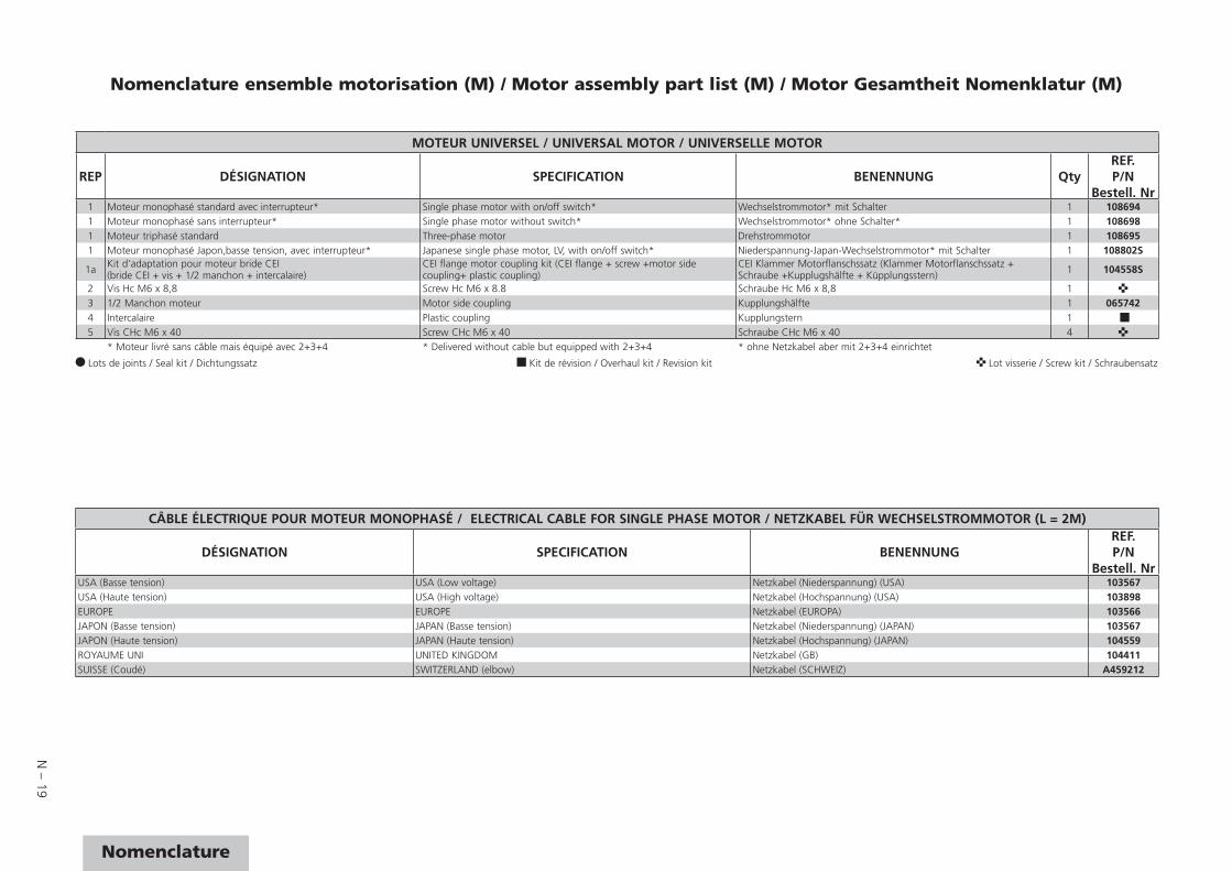
Nomenclature ensemble motorisation (M) / Motor assembly part list (M) / Motor Gesamtheit Nomenklatur (M)
MOTEUR UNIVERSEL / UNIVERSAL MOTOR / UNIVERSELLE MOTOR
REP DÉSIGNATION SPECIFICATION BENENNUNG QtyREF.P/N
Bestell. Nr1 Moteur monophasé standard avec interrupteur* Single phase motor with on/off switch* Wechselstrommotor* mit Schalter 1 1086941 Moteur monophasé sans interrupteur* Single phase motor without switch* Wechselstrommotor* ohne Schalter* 1 1086981 Moteur triphasé standard Three-phase motor Drehstrommotor 1 1086951 Moteur monophasé Japon,basse tension, avec interrupteur* Japanese single phase motor, LV, with on/off switch* Niederspannung-Japan-Wechselstrommotor* mit Schalter 1 108802S
1a Kit d’adaptation pour moteur bride CEI (bride CEI + vis + 1/2 manchon + intercalaire)
CEI flange motor coupling kit (CEI flange + screw +motor side coupling+ plastic coupling)
CEI Klammer Motorflanschssatz (Klammer Motorflanschssatz + Schraube +Kupplugshälfte + Küpplungsstern) 1 104558S
2 Vis Hc M6 x 8,8 Screw Hc M6 x 8.8 Schraube Hc M6 x 8,8 1 3 1/2 Manchon moteur Motor side coupling Kupplungshälfte 1 0657424 Intercalaire Plastic coupling Kupplungstern 1 5 Vis CHc M6 x 40 Screw CHc M6 x 40 Schraube CHc M6 x 40 4
* Moteur livré sans câble mais équipé avec 2+3+4 * Delivered without cable but equipped with 2+3+4 * ohne Netzkabel aber mit 2+3+4 einrichtet
Lots de joints / Seal kit / Dichtungssatz Kit de révision / Overhaul kit / Revision kit Lot visserie / Screw kit / Schraubensatz
CÂBLE ÉLECTRIQUE POUR MOTEUR MONOPHASÉ / ELECTRICAL CABLE FOR SINGLE PHASE MOTOR / NETZKABEL FÜR WECHSELSTROMMOTOR (L = 2M)
DÉSIGNATION SPECIFICATION BENENNUNGREF.P/N
Bestell. NrUSA (Basse tension) USA (Low voltage) Netzkabel (Niederspannung) (USA) 103567USA (Haute tension) USA (High voltage) Netzkabel (Hochspannung) (USA) 103898EUROPE EUROPE Netzkabel (EUROPA) 103566JAPON (Basse tension) JAPAN (Basse tension) Netzkabel (Niederspannung) (JAPAN) 103567JAPON (Haute tension) JAPAN (Haute tension) Netzkabel (Hochspannung) (JAPAN) 104559ROYAUME UNI UNITED KINGDOM Netzkabel (GB) 104411SUISSE (Coudé) SWITZERLAND (elbow) Netzkabel (SCHWEIZ) A459212
N – 20
8
9
7
12
3
45
6
C
BA or
Plan du système bulleurBubbler system drawingBubbler system Gesamtplan
Nomenclature du système bulleur / Bubbler system part list / Bubbler system Nomenklatur
REP DÉSIGNATION SPECIFICATION BENENNUNG
Types/modelREF.P/N
Bestell. Nr
2010
C2
2015
C2
2021
C2
1 Bouchon 1/8 NPT Plug 1/8 NPT Blindstopfen 1/8 NPT 1 1 1 0829262 Manchon Coupling Kupplung 1 1 1 0658663 Ruban teflon Teflon band Teflon band 1 1 1 0609754 Bille inox 18/8 d. 5,8 Ball 18/8 d. 5.8 Kugel 18/8 d, 5,8 1 1 1 0875935 Ressort Spring Feder 1 1 1 0651496 Raccord G 1/8 -1/8 NPT Connector G 1/8 -1/8 NPT Verbindungselement 1 1 1 0658677 Joint torique c 1,9 - d 7,2 O-ring c 1.9 - d 7.2 Dichtung c 1,9 - d 7,2 1 1 18 Bulleur Bubbler Bubler 1 1 0658368 Bulleur Bubbler Bubler 1 0658359 Attache tube Tube fastener Rohrbefestigung 1 1 1 065835
Lots de joints / Seal kit / Dichtungssatz Kit de révision / Overhaul kit / Revision kit Lot visserie / Screw kit / Schraubensatz
N – 21
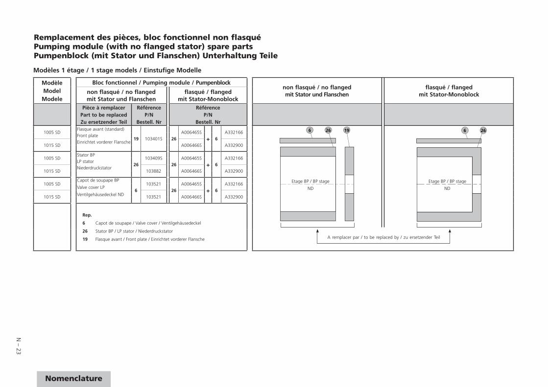
Nomenclature
ModèleModelModele
Bloc fonctionnel / Pumping module / Pumpenblocknon flasqué / no flangedmit Stator und Flanschen
flasqué / flangedmit Stator-Monoblocknon flasqué / no flanged
mit Stator und Flanschenflasqué / flanged
mit Stator-MonoblockPièce à remplacer
Part to be replacedZu ersetzender Teil
RéférenceP/N
Bestell. Nr
RéférenceP/N
Bestell. Nr2005 C1 Flasque avant (C)
19 103396S
26
A006037S
+ 17
-
6 34 29 17 26 19 6 34 17 26
2010 C1 / C2 Front plate A006038S A3321762015 C1 / C2 Einrichtet vorderer Flansche A006039S A3322662021 C1 / C2 A006040S A332175
2005 I / SD / SDI Flasque avant (standard)
19 103401S
A006001S -2010 I / SD Front plate A006000S A3321762015 I / SD Einrichtet vorderer Flansche A005999S A3322662021 I / SD A005997S A3321752005 C1 Flasque médian (C)
29 103410S
34
A006042S
+ 6 A332166
2010 C1 / C2 Central plate2015 C1 / C2 Zwischenflansche2021 C1 / C22005 I / SD Flasque médian (standard)
29103408S A005996S2010 I / SD Central plate
2015 I / SD Zwischenflansche2021 I / SD2005 SDI * 105639 A006496S2005 C1 Stator HP
34103409S
34
A006042S
+ 6 A332166
Rep.
6 Capot de soupape HP / Valve cover HP / Ventilgehäusedeckel HD
34 Stator HP / HP stator / Hochdruckstator
29 Flasque médian / Central plate / Zwischenflansche
17 Capot de soupape BP / Valve cover LP / Ventilgehäusedeckel ND
26 Stator BP / LP stator / Niederdruckstator
19 Flasque avant / Front plate / Einrichtet vorderer Flansche
2010 C1 / C2 HP stator2015 C1 / C2 Hochdruckstator2021 C1 / C22005 I / SD
A005996S2010 I / SD2015 I / SD2021 I / SD2005 SDI * 065722S A006496S
2005 I / SD / SDI Stator BP
26
103507S
26
A006001S
+ 17
-2005 C1 LP stator A006037S
2010 I / SD Niederdruckstator103512S
A006000SA332176
2010 C1 / C2 A006038S2015 I / SD
103510SA005999S
A3322662015 C1 / C2 A006039S2021 I / SD
103393SA005997S
A3321752021 C1 / C2 A006040S
Remplacement des pièces du bloc fonctionnel non flasquéPumping module (with no flanged stator) spare partsPumpenblock (mit Stator und Flanschen) Unterhaltung Teile
A remplacer par / to be replaced by / zu ersetzender Teil
Etage HP
HP stage
HD
Etage BP
LP stage
ND
Etage HP
HP stage
HD
Etage BP
LP stage
ND
Modèles 2 étages / 2 stage models / Zweistufige Modelle
A remplacer par / to be replaced by / zu ersetzender Teil
* Dans ce cas, changer également le rotor HP (31) (voir nomenclature du bloc fonctionnel avec stator flasqué (C) (page N-13)) et utiliser le kit de révision SDI (voir page 47).* In this case, replace also HP rotor (31) (refer to pumping module with flanged stator (C) (page N-13)) and use a SDI Overhaul kit (see page 47).* In diesem Fall ebenfalls den Hochdruckrotor (31) auswechseln (siehe Nomenklatur des Funktionsblocks mit geflanschtem Stator (Alter N - 13)) und SDI-Revision kit verwenden (siehe Seite 47).
N – 22
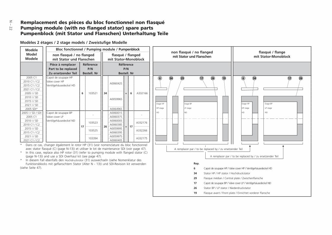
Remplacement des pièces du bloc fonctionnel non flasquéPumping module (with no flanged stator) spare partsPumpenblock (mit Stator und Flanschen) Unterhaltung Teile
ModèleModelModele
Bloc fonctionnel / Pumping module / Pumpenblocknon flasqué / no flangedmit Stator und Flanschen
flasqué / flangemit Stator-Monoblocknon flasqué / no flanged
mit Stator und Flanschenflasqué / flanged
mit Stator-MonoblockPièce à remplacer
Part to be replacedZu ersetzender Teil
RéférenceP/N
Bestell. Nr
RéférenceP/N
Bestell. Nr2005 C1 Capot de soupape HP
6 103521 34
A006042S
+ 6 A332166
6 34 29 17 26 19 6 34 17 262010 C1 / C2 Valve cover HP2015 C1 / C2 Ventilgehäusedeckel HD2021 C1 / C22005 I / SD
A005996S2010 I / SD2015 I / SD2021 I / SD2005 SDI* A006496S
2005 I / SD / SDI Capot de soupape BP
17
-
26
A006001S
+ 17
-2005 C1 Valve cover LP A006037S
2010 I / SD Ventilgehäusedeckel ND103523
A006000SA332176
2010 C1 / C2 A006038S2015 I / SD
103525A005999S
A3322662015 C1 / C2 A006039S2021 I / SD
103394A005997S
A3321752021 C1 / C2 A006040S
Rep.
6 Capot de soupape HP / Valve cover HP / Ventilgehäusedeckel HD
34 Stator HP / HP stator / Hochdruckstator
29 Flasque médian / Central plate / Zwischenflansche
17 Capot de soupape BP / Valve cover LP / Ventilgehäusedeckel ND
26 Stator BP / LP stator / Niederdruckstator
19 Flasque avant / Front plate / Einrichtet vorderer Flansche
A remplacer par / to be replaced by / zu ersetzender Teil
A remplacer par / to be replaced by / zu ersetzender Teil
Etage HP
HP stage
HD
Etage BP
LP stage
ND
Etage HP
HP stage
HD
Etage BP
LP stage
ND
Modèles 2 étages / 2 stage models / Zweistufige Modelle
* Dans ce cas, changer également le rotor HP (31) (voir nomenclature du bloc fonctionnel avec stator flasqué (C) (page N-13)) et utiliser le lot de maintenance SDI (voir page 47).* In this case, replace also HP rotor (31) (refer to pumping module with flanged stator (C) (page N-13)) and use a SDI Overhaul kit (see page 47).* In diesem Fall ebenfalls den Hochdruckrotor (31) auswechseln (siehe Nomenklatur des Funktionsblocks mit geflanschtem Stator (Alter N - 13)) und SDI-Revision kit verwenden (siehe Seite 47).
N – 23
Nomenclature
ModèleModelModele
Bloc fonctionnel / Pumping module / Pumpenblocknon flasqué / no flangedmit Stator und Flanschen
flasqué / flangedmit Stator-Monoblocknon flasqué / no flanged
mit Stator und Flanschenflasqué / flanged
mit Stator-MonoblockPièce à remplacer
Part to be replacedZu ersetzender Teil
RéférenceP/N
Bestell. Nr
RéférenceP/N
Bestell. Nr
1005 SDFlasque avant (standard)
19 103401S 26A006465S
+ 6A332166 196 26
266Front plate
1015 SDEinrichtet vorderer Flansche
A006466S A332900
1005 SDStator BP
26103409S
26A006465S
+ 6A332166
LP stator
1015 SDNiederdruckstator
103882 A006466S A332900
1005 SDCapot de soupape BP
Valve cover LP
Ventilgehäusedeckel ND6
10352126
A006465S
+ 6A332166
1015 SD 103521 A006466S A332900
Rep.
6 Capot de soupape / Valve cover / Ventilgehäusedeckel
26 Stator BP / LP stator / Niederdruckstator
19 Flasque avant / Front plate / Einrichtet vorderer Flansche
Remplacement des pièces, bloc fonctionnel non flasquéPumping module (with no flanged stator) spare partsPumpenblock (mit Stator und Flanschen) Unterhaltung Teile
A remplacer par / to be replaced by / zu ersetzender Teil
Etage BP / BP stage
ND
Etage BP / BP stage
ND
Modèles 1 étage / 1 stage models / Einstufige Modelle
VACUUM SOLUTIONS FROM A SINGLE SOURCEVACUUM SOLUTIONS FROM A SINGLE SOURCEPfeiffer Vacuum stands for innovative and custom vacuum solutions worldwide, Pfeiffer Vacuum stands for innovative and custom vacuum solutions worldwide,
technological perfection, competent advice and reliable service. technological perfection, competent advice and reliable service.
COMPLETE RANGE OF PRODUCTSCOMPLETE RANGE OF PRODUCTSFrom a single component to complex systems:From a single component to complex systems:We are the only supplier of vacuum technology that provides a complete product portfolio. We are the only supplier of vacuum technology that provides a complete product portfolio.
COMPETENCE IN THEORY AND PRACTICECOMPETENCE IN THEORY AND PRACTICEBenefi t from our know-how and our portfolio of training opportunities!Benefi t from our know-how and our portfolio of training opportunities!We support you with your plant layout and provide fi rst-class on-site service worldwide.We support you with your plant layout and provide fi rst-class on-site service worldwide.
Are you looking for aAre you looking for a
perfect vacuum solution?perfect vacuum solution?Please contact us:Please contact us:
Pfeiffer Vacuum GmbHPfeiffer Vacuum GmbHHeadquarters • GermanyHeadquarters • GermanyT +49 6441 802-0T +49 6441 802-0
[email protected]@pfeiffer-vacuum.de
www.pfeiffer-vacuum.comwww.pfeiffer-vacuum.com
Ed
03 -
Dat
e 20
15/1
0 - P
/N: 1
0327
5ME
NE
d 03
- D
ate
2015
/10
- P/N
: 103
275M
EN
*103275*