Maintenance Bypass Box for Parallel UPSs Installation & Operation Guide
2
Maintenance Bypass Box for Parallel UPSs Installation & Operation Guide About this Guide This guide contains information about installing and operating the Delta Maintenance Bypass Box for Parallel UPSs (MBB-P). Before you install this unit, please read the safety instructions below. Save these Instructions This guide contains instructions and warnings that should be followed during the installation, operation and storage of this product. Failure to heed these instructions and warnings will void the product warranty. This product is designed for indoor use only in a controlled environment away from excess moisture, temperature extremes, conductive contaminants, dust or direct sunlight. • Do not connect the MBB-P to an ungrounded outlet or extension cords or adapters that eliminate the connection to ground • Do not use this equipment in the presence of flammable substances. • The power requirement for each piece of equipment connected to the MBB must not exceed the individual outlet's load rating. • Do not drill into or attempt to open any part of the MBB housing. There are no user serviceable parts inside. • Do not modify the MBB-P. • Do not use the MBB-P if any part of it becomes damaged. • Never install electrical equipment during a thunderstorm. Safety Precautions To reduce the risk of personal injury from electric shock, you must observe the following safety precautions when placing, installing, operating, or performing maintenance on the Delta MBB-P. Warnings! • Elevated Operating Ambient - If installed in a closed or multi-unit rack assembly, the operating ambient temperature of the rack environment may be greater than room ambient. Therefore, consideration should be given to installing the equipment in an environment compatible with the maximum ambient temperature (Tma) specified by the manufacturer. • Reduced Air Flow - Installation of the equipment in a rack should be such that the amount of air flow required for safe operation of the equipment is not compromised. • Mechanical Loading - Mounting of the equipment in the rack should be such that a hazardous condition is not achieved due to uneven mechanical loading. • Circuit Overloading - Consideration should be given to the connection of the equipment to the supply circuit and the effect that overloading of the circuits might have on over-current protection and supply wiring. Appropriate consideration of equipment nameplate ratings should be used when addressing this concern. • Reliable Earthing - Reliable earthing of rack-mounted equipment should be maintained. Particular attention should be given to supply connections other than direct connections to the branch circuit (such as use of power strips). Precautions for Rack Mounting Delta strongly recommends that you do not perform maintenance on the MBB-P if it is receiving input power. • To reduce your risk of personal injury by electric shock, you must: • Be a certified electrician trained in live electrical installation • Always work with another qualified person • Know how to disconnect electricity to the MBB and data center in case of emergency • Wear the right protective equipment • Use double-insulated tools • Strictly follow local and site regulations Maintenance with Input Power This is a Class A product. In a domestic environment this product may cause radio interference in which case the user may be required to take adequate measures. Electromagnetic Interference The Delta Maintenance Bypass Box for Parallel UPSs (MBB-P) lets you isolate a single UPS from the load without interrupting power to essential applications. In addition, the MBB-P connects to a parallel UPS to provide redundant power protection for the UPS that is undergoing maintenance. This allows you to perform scheduled UPS maintenance or UPS replacement without disrupting power, while maintaining UPS redundancy. The MBB-P easily transfers power between normal and bypass mode using a rotary switch. 1. MBB-P Overview The Delta MBB-P package should contain the following items: 2. Package Contents 3. Installing the MBB-P CAUTION: • A licensed electrician must install the Delta MBB-P. • The two UPS units must be switched off and unplugged before installation. • Install a utility circuit breaker for input wiring. Refer to the drawing & table below. Quantity Item 1pcs MBB-P 1set Fixing Plate 1set Ear bracket 2pcs Parallel Cable 1pcs MBB-P Installation & Operation Guide 6pcs Cable gland 18pcs Terminal System Voltage Current Full Load Nominal External Input Circuit Breaker Typical Wire Size Typical (mm 2 ) WIRE1 WIRE2 Input Output Input Output For 5/7k UPS For 9/11k UPS For 5/7k UPS For 9/11k UPS MBB-P 200/208/220/ 230/240Vac 1Phase 63A 63A 2Pole 10 10 8 10 Remark: The External Input Circuit Breaker must use the components approved for its safety certification. 4. Fixing the MBB-P 4-1. Tower Configuration 1. Place the MBB-P on the top rear of the UPS unit. 2. Locate and align the fixing holes on the MBB-P and UPS unit.Use a screwdriver to fasten the fixing plates with the provided screws and attach the MBB-P to the UPS unit. 3. Place the UPS and MBB-P in the upright tower position and secure the mounting feet. x8 4-2. Rack-mount Configuration 1. Attach the mounting brackets to the MBB-P using the M4*6mm screws that came with the brackets. 2. Choose a location in the rack for the MBB-P. 3. Install the MBB-P on your rack using the screws and cage nuts. (The screws and cage nuts are provided with the rack frame.) Fig. 2 5. Making Connections The steps below show you how to connect power cables so the path of AC power flows through the MBB-P to the two UPS units, or alternately, bypassing UPS1 and through UPS2 to the connected load. Fig. 3 5-2. Attach the cable glands to the cable entry box of UPS2. Unscrew and pull out the tray of UPS2 terminal block from the enclosure. Insert the cables through the cable glands and then insert the leads of the cables into the terminal blocks of UPS2 and fasten screws. See Fig. 4. Fig. 4 5-1. Unscrew and remove the cable entry boxes on the MBB-P. See Fig. 3. (The mounting feet are provided with the UPS or from a dealer.) Fig. 1 MBB-P N L N L TO UPS2 OUTPUT TO UPS2 INPUT x6 x4 x4 OUTPUT UPS 2 INPUT UPS 2
-
Upload
delta-electronics-inc -
Category
Documents
-
view
236 -
download
2
Transcript of Maintenance Bypass Box for Parallel UPSs Installation & Operation Guide

Maintenance Bypass Box
for Parallel UPSs
Installation & Operation Guide
About this GuideThis guide contains information about installing and operating the Delta Maintenance Bypass Box for Parallel UPSs (MBB-P). Before you install this unit, please read the safety instructions below.
Save these Instructions This guide contains instructions and warnings that should be followed during the installation, operation and storage of this product. Failure to heed these instructions and warnings will void the product warranty.
This product is designed for indoor use only in a controlled environment away from excess moisture, temperature extremes, conductive contaminants, dust or direct sunlight.
• Do not connect the MBB-P to an ungrounded outlet or extension cords or adapters that eliminate the connection to ground• Do not use this equipment in the presence of flammable substances.• The power requirement for each piece of equipment connected to the MBB must not exceed the individual outlet's load rating.• Do not drill into or attempt to open any part of the MBB housing. There are no user serviceable parts inside.• Do not modify the MBB-P.• Do not use the MBB-P if any part of it becomes damaged.• Never install electrical equipment during a thunderstorm.
Safety PrecautionsTo reduce the risk of personal injury from electric shock, you must observe the following safety precautions when placing, installing, operating, or performing maintenance on the Delta MBB-P.
Warnings!
• Elevated Operating Ambient - If installed in a closed or multi-unit rack assembly, the operating ambient temperature of the rack environment may be greater than room ambient. Therefore, consideration should be given to installing the equipment in an environment compatible with the maximum ambient temperature (Tma) specified by the manufacturer.• Reduced Air Flow - Installation of the equipment in a rack should be such that the amount of air flow required for safe operation of the equipment is not compromised.• Mechanical Loading - Mounting of the equipment in the rack should be such that a hazardous condition is not achieved due to uneven mechanical loading.• Circuit Overloading - Consideration should be given to the connection of the equipment to the supply circuit and the effect that overloading of the circuits might have on over-current protection and supply wiring. Appropriate consideration of equipment nameplate ratings should be used when addressing this concern.• Reliable Earthing - Reliable earthing of rack-mounted equipment should be maintained. Particular attention should be given to supply connections other than direct connections to the branch circuit (such as use of power strips).
Precautions for Rack Mounting
Delta strongly recommends that you do not perform maintenance on the MBB-P if it is receiving input power.
• To reduce your risk of personal injury by electric shock, you must:• Be a certified electrician trained in live electrical installation• Always work with another qualified person• Know how to disconnect electricity to the MBB and data center in case of emergency• Wear the right protective equipment• Use double-insulated tools• Strictly follow local and site regulations
Maintenance with Input Power
This is a Class A product. In a domestic environment this product may cause radio interference in which case the user may be required to take adequate measures.
Electromagnetic Interference
The Delta Maintenance Bypass Box for Parallel UPSs (MBB-P) lets you isolate a single UPS from the load without interrupting power to essential applications. In addition, the MBB-P connects to a parallel UPS to provide redundant power protection for the UPS that is undergoing maintenance. This allows you to perform scheduled UPS maintenance or UPS replacement without disrupting power, while maintaining UPS redundancy. The MBB-P easily transfers power between normal and bypass mode using a rotary switch.
1. MBB-P Overview
The Delta MBB-P package should contain the following items:
2. Package Contents
3. Installing the MBB-PCAUTION: • A licensed electrician must install the Delta MBB-P. • The two UPS units must be switched off and unplugged before installation. • Install a utility circuit breaker for input wiring. Refer to the drawing & table below.
Quantity Item
1pcs MBB-P
1set Fixing Plate
1set Ear bracket
2pcs Parallel Cable
1pcs MBB-P Installation & Operation Guide
6pcs Cable gland
18pcs Terminal
System
Voltage Current Full Load Nominal
External Input
Circuit Breaker Typical
Wire Size Typical (mm2)
WIRE1 WIRE2
Input Output Input OutputFor 5/7k UPS
For 9/11k UPS
For 5/7k UPS
For 9/11k UPS
MBB-P200/208/220/230/240Vac
1Phase63A 63A
2Pole 10 10 8 10
Remark: The External Input Circuit Breaker must use the components approved for its safety certification.
4. Fixing the MBB-P 4-1. Tower Configuration1. Place the MBB-P on the top rear of the UPS unit.2. Locate and align the fixing holes on the MBB-P and UPS unit.Use a screwdriver to fasten the fixing plates with the provided screws and attach the MBB-P to the UPS unit.3. Place the UPS and MBB-P in the upright tower position and secure the mounting feet.
x8
4-2. Rack-mount Configuration1. Attach the mounting brackets to the MBB-P using the M4*6mm screws that came with the brackets.
2. Choose a location in the rack for the MBB-P. 3. Install the MBB-P on your rack using the screws and cage nuts.
(The screws and cage nuts are provided with the rack frame.)Fig. 2
5. Making ConnectionsThe steps below show you how to connect power cables so the pathof AC power flows through the MBB-P to the two UPS units, or alternately, bypassing UPS1 and through UPS2 to the connected load.
Fig. 3
5-2. Attach the cable glands to the cable entry box of UPS2. Unscrew and pull out the tray of UPS2 terminal block from the enclosure. Insert the cables through the cable glands and then insert the leads of the cables into the terminal blocks of UPS2 and fasten screws. See Fig. 4.
Fig. 4
5-1. Unscrew and remove the cable entry boxes on the MBB-P. See Fig. 3.
(The mounting feet are provided with the UPS or from a dealer.)
Fig. 1
MBB-P
NL N LTO UPS2 OUTPUT TO UPS2 INPUT
x6
x4
x4
OUTPUT UPS 2
INPUT UPS 2
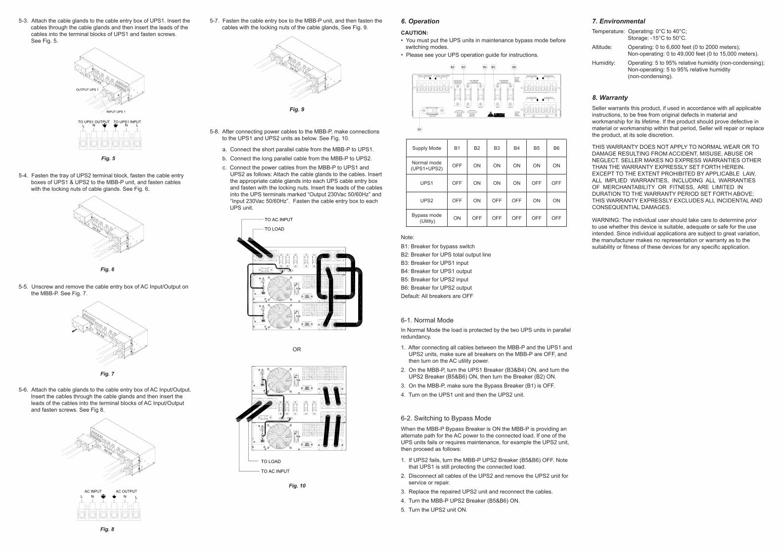
a. Connect the short parallel cable from the MBB-P to UPS1. b. Connect the long parallel cable from the MBB-P to UPS2. c. Connect the power cables from the MBB-P to UPS1 and UPS2 as follows: Attach the cable glands to the cables. Insert the appropriate cable glands into each UPS cable entry box and fasten with the locking nuts. Insert the leads of the cables into the UPS terminals marked “Output 230Vac 50/60Hz” and “Input 230Vac 50/60Hz”. Fasten the cable entry box to each UPS unit.
5-8. After connecting power cables to the MBB-P, make connections to the UPS1 and UPS2 units as below. See Fig. 10.
5-4. Fasten the tray of UPS2 terminal block, fasten the cable entry boxes of UPS1 & UPS2 to the MBB-P unit, and fasten cables with the locking nuts of cable glands. See Fig. 6.
Fig. 6
5-6. Attach the cable glands to the cable entry box of AC Input/Output. Insert the cables through the cable glands and then insert the leads of the cables into the terminal blocks of AC Input/Output and fasten screws. See Fig 8.
5-7. Fasten the cable entry box to the MBB-P unit, and then fasten the cables with the locking nuts of the cable glands, See Fig. 9.
5-5. Unscrew and remove the cable entry box of AC Input/Output on the MBB-P. See Fig. 7.
Fig. 7
Fig. 8
Fig. 9
CAUTION: • You must put the UPS units in maintenance bypass mode before switching modes. • Please see your UPS operation guide for instructions.
6. Operation
Supply Mode B1 B2 B3 B4 B5 B6
Normal mode (UPS1+UPS2) OFF ON ON ON ON ON
UPS1 OFF ON ON ON OFF OFF
UPS2 OFF ON OFF OFF ON ON
Bypass mode (Ulitity) ON OFF OFF OFF OFF OFF
Note:B1: Breaker for bypass switch B2: Breaker for UPS total output line B3: Breaker for UPS1 input B4: Breaker for UPS1 output
B5: Breaker for UPS2 input B6: Breaker for UPS2 outputDefault: All breakers are OFF
In Normal Mode the load is protected by the two UPS units in parallel redundancy.
6-1. Normal Mode
1. After connecting all cables between the MBB-P and the UPS1 and UPS2 units, make sure all breakers on the MBB-P are OFF, and then turn on the AC utility power.2. On the MBB-P, turn the UPS1 Breaker (B3&B4) ON, and turn the UPS2 Breaker (B5&B6) ON, then turn the Breaker (B2) ON.3. On the MBB-P, make sure the Bypass Breaker (B1) is OFF.4. Turn on the UPS1 unit and then the UPS2 unit.
When the MBB-P Bypass Breaker is ON the MBB-P is providing an alternate path for the AC power to the connected load. If one of the UPS units fails or requires maintenance, for example the UPS2 unit, then proceed as follows:
6-2. Switching to Bypass Mode
1. If UPS2 fails, turn the MBB-P UPS2 Breaker (B5&B6) OFF. Note that UPS1 is still protecting the connected load.2. Disconnect all cables of the UPS2 and remove the UPS2 unit for service or repair.3. Replace the repaired UPS2 unit and reconnect the cables.4. Turn the MBB-P UPS2 Breaker (B5&B6) ON.5. Turn the UPS2 unit ON.
Temperature: Operating: 0°C to 40°C; Storage: -15°C to 50°C.Altitude: Operating: 0 to 6,600 feet (0 to 2000 meters); Non-operating: 0 to 49,000 feet (0 to 15,000 meters).Humidity: Operating: 5 to 95% relative humidity (non-condensing); Non-operating: 5 to 95% relative humidity (non-condensing).
7. Environmental
Seller warrants this product, if used in accordance with all applicable instructions, to be free from original defects in material and workmanship for its lifetime. If the product should prove defective in material or workmanship within that period, Seller will repair or replace the product, at its sole discretion.
8. Warranty
THIS WARRANTY DOES NOT APPLY TO NORMAL WEAR OR TO DAMAGE RESULTING FROM ACCIDENT, MISUSE, ABUSE OR NEGLECT. SELLER MAKES NO EXPRESS WARRANTIES OTHER THAN THE WARRANTY EXPRESSLY SET FORTH HEREIN. EXCEPT TO THE EXTENT PROHIBITED BY APPLICABLE LAW, ALL IMPLIED WARRANTIES, INCLUDING ALL WARRANTIES OF MERCHANTABILITY OR FITNESS, ARE LIMITED IN DURATION TO THE WARRANTY PERIOD SET FORTH ABOVE; THIS WARRANTY EXPRESSLY EXCLUDES ALL INCIDENTAL AND CONSEQUENTIAL DAMAGES.
WARNING: The individual user should take care to determine prior to use whether this device is suitable, adequate or safe for the use intended. Since individual applications are subject to great variation, the manufacturer makes no representation or warranty as to the suitability or fitness of these devices for any specific application.
Fig. 10
OR
NL N LAC INPUT AC OUTPUT
5-3. Attach the cable glands to the cable entry box of UPS1. Insert the cables through the cable glands and then insert the leads of the cables into the terminal blocks of UPS1 and fasten screws. See Fig. 5.
Fig. 5
NL N LTO UPS1 OUTPUT TO UPS1 INPUT
B2
AC INPUT 230Vac 50/60Hz
LNL N
AC OUTPUT 230Vac 50/60Hz
INPUT OUTPUT INPUT OUTPUT
TO UPS2TO UPS1
LNL NTO UPS1230Vac 50/60Hz
TO UPS1 OUTPUT
LNL N
TO UPS2230Vac 50/60Hz
TO UPS1 INPUT
TO UPS2 OUTPUT TO UPS2 INPUT
B1
B3 B4 B5 B6
OUTPUT UPS 1
INPUT UPS 1
TO AC INPUT
TO LOAD
TO AC INPUT
TO LOAD