MAINTENANCE AND OPERATION OF WATER SUPPLY …rdso.indianrailways.gov.in/works/uploads/File/Handbook...
83
CAMTECH/C/2001/WTP/1.0 Water Treatment Plant August - 2001 1 GOVERNMENT OF INDIA MINISTRY OF RAILWAYS For Official Use Only WATER TREATMENT PLANT CAMTECH/2001/C/WTP/1.0 August - 2001 Centre for Advanced Maintenanc e TECH nology Excellence in Maintenance Maharajpur, GWALIOR - 474 020
Transcript of MAINTENANCE AND OPERATION OF WATER SUPPLY …rdso.indianrailways.gov.in/works/uploads/File/Handbook...

CAMTECH/C/2001/WTP/1.0
Water Treatment Plant August - 2001
1
GOVERNMENT OF INDIA
MINISTRY OF RAILWAYS
For Official Use Only
WATER TREATMENT PLANT
CAMTECH/2001/C/WTP/1.0
August - 2001
Centre
for
Advanced
Maintenance
TECHnology
Excellence in Maintenance
Maharajpur, GWALIOR - 474 020

CAMTECH/C/2001/WTP/1.0
Water Treatment Plant August - 2001
Foreword
Water Treatment Plant plays an important role in water
supply system network.
Its proper and regular function ensures the provision of
safe and adequate potable water to the user. This book draws
the focus on the operation and maintenance aspects of water
treatment plant. Inspection schedule as laid down in IRWM,
routine-abnormal operational and maintenance instructions as
described in various codes and books are incorporated as a
ready reckoner to the personnel, dealing with water supply
system.
I am sure this book would be of considerable help to all
Civil Engg. Personnel for improvement in maintenance and
handling of water treatment plant.
CAMTECH, Gwalior M.L.Gupta
Date : 31.08.2001 Executive Director

CAMTECH/C/2001/WTP/1.0
Water Treatment Plant August - 2001
Preface
Potable water is the one of the fundamental
requirements of civilisation. Our Engg. department bearing the
responsibility of effective arrangement of water supply for all
Railway Stations, offices and colonies of Indian Railways.
We are using different kind of resources of water, as
per the availability at that nearby place, like river, lakes,
borewell etc.. Many places Engg. Department has established
their own water treatment plants, to meet the demand of
potable drinking water, so the maintenance of water treatment
plant and their management has become an important aspect
for Engg. department. The main objective of this book to
provide a concise and complete knowledge regarding
maintenance problems and their remedies, which are coming in
day to day operation and maintenance of water treatment plant.
This handbook does not supersede any existing
instruction from Railway Board, IRPWM, RDSO etc. except
where necessary correction slips intimating the required
changes are issued by Railway Board/RDSO.

CAMTECH/C/2001/WTP/1.0
Water Treatment Plant August - 2001
I am grateful for the assistance given to me by
Shri Anupam Sharma, CTA/Civil/CAMTECH, who went
through the complete text, collected information, data etc. and
done editing work. Nice data entry has been done by Shri
Ramesh Bhojwani, CO/CAMTECH.
We welcome any suggestion for improvements from
our readers.
CAMTECH, Gwalior J.K.Nandanwar
Date : 31.08.2001 Director/Civil
CAMTECH/C/2001/WTP/1.0
Water Treatment Plant August - 2001
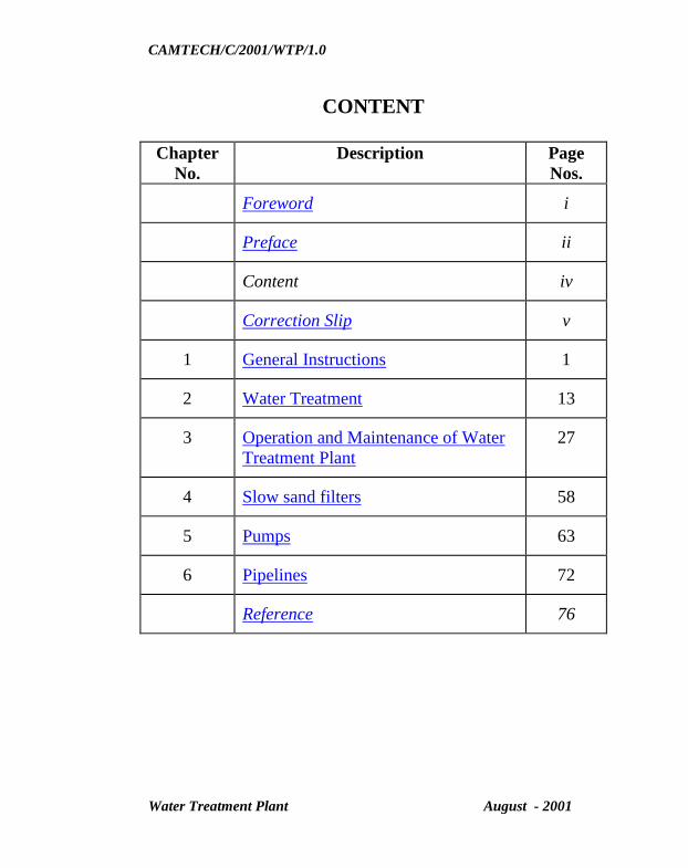
CONTENT
Chapter
No.
Description Page
Nos.
Foreword i
Preface ii
Content iv
Correction Slip v
1 General Instructions 1
2 Water Treatment 13
3 Operation and Maintenance of Water
Treatment Plant
27
4 Slow sand filters 58
5 Pumps 63
6 Pipelines 72
Reference 76

CAMTECH/C/2001/WTP/1.0
Water Treatment Plant August - 2001
ISSUE OF CORRECTION SLIPS
The correction slips to be issued in future for this
handbook will be numbered as follows:
CAMTECH/C/2001/WTP/1.0/CS. # XX date ............
Where “XX” is the serial number of the concerned
correction slip (starting from 01 onwards).
CORRECTION SLIPS ISSUED Sr. No.
of
C.Slip
Date of
issue
Page no. and Item
No. modified
Remarks
GO TO INDEX
CAMTECH/C/2001/WTP/1.0
Water Treatment Plant August - 2001
1
CHAPTER - 1
GENERAL INSTRUCTIONS
Joint operating, Engineering, Mechanical Engineering and
Electrical Engineering Department’s Circular
No. 92/Ele. (G)/150/12 :
(Authority : Central Rly.'s Circular No. 92/Ele. (G)/150/12)
Procurement, Installation, Operation and Maintenance of
pumps for water supply installations :
1. Introduction
1.1 Consequent upon large scale dieselisation
electrification, replacement of bulk of steam traction on
the one hand & provision of electric pumps substituting
the steam and diesel pumps and providing diesel pumps
only as a stand by, on the other hand, the need for
redefining the responsibilities in respect of
procurement, installation, operation and maintenance of
pumps has arisen. This joint circular is, therefore,
issued in super session of the earlier circular issued on
08.3.1972.
1.2 These instructions will come into force with effect from
01.10.94.
CAMTECH/C/2001/WTP/1.0
Water Treatment Plant August - 2001
2. Procurement and installation :
2.1 Electric pumps and diesel pumps :
2.1.1 Electrical department shall be responsible for
procurement, installation and operation of
electrical pumps whether permanent or
temporary including those at filtration plants
meant for domestic water supply. Stand by
diesel pumps should be dispensed with
gradually, wherever possible and where stand by
is a must, the existing stand by diesel pumps
will continue to be maintained by Mechanical
department. In case any of these diesel pumps
are due for replacement and at the condemning
stage these will be replaced by diesel generating
sets of minimum required capacity to drive the
existing electric pumps. Such stand by sets are
to be identified jointly by divisional officers of
Electrical and Mechanical branch. The
procurement and maintenance of diesel
generating sets with associated switch gear will
be the responsibility of Electrical department.
The existing operating and maintenance staff of
Mechanical department should be re-
deployed/transferred for use of Electrical
department.
2.1.2 At locations where there are no electric pumps
and only diesel pumps are provided, these will
be installed by Mechanical department. At such
CAMTECH/C/2001/WTP/1.0
Water Treatment Plant August - 2001
locations, if it’s replacement is to be done with
electric pump, the entire process of procurement
of electric pumps and their process of
procurement of electric pumps and their
installation will be done by Electrical
department. Staff under Mechanical department
should be re-deployed for maintenance of
electric pumps which have replaced the diesel
pumps.
2.2 Water main and control valves :
2.2.1 The responsibility for procurement, installation
and laying of water supply distribution system
including the controlling valves shall be
responsibility of the Civil Engineering
department.
The non return valves, in case these are provided
alongwith the pumps, electric or diesel shall be
procured and installed by the
Electrical/Mechanical department along with the
pumps. Except foot valve all other control valves
and non return valves should be procured and
maintained by Engineering department.
2.2.2 Procurement of valves for replacement shall be
done by Engineering department which is
responsible for maintenance of the system
alongwith control valves.
CAMTECH/C/2001/WTP/1.0
Water Treatment Plant August - 2001
3. Operation
3.1 Electric pumps
3.1.1 Operation of electric pumps/diesel stand by
pumps meant for supply of raw water from main
source from river or Municipal Corporation,
Reservoirs shall be the responsibility of the
Electrical Department. Further responsibility of
control of electric pumps has been decided by the
Board vide Board’s letter no. 92/Elec (G)/150/12
dated : 26.8.92, according to which control over
such pumps will be as indicated below :
(A) At smaller stations where neither electrical non
engineering supervisors are head quartered:-
under station master.
(B) At stations, where an engineering supervisor is
headquartered, but not electrical supervisor is
headquartered:- under Engineering supervisor.
(C) At stations having both engineering and electrical
supervisors are headquartered:- existing
arrangements to continue.
(D) Repairs and maintenance of electrical equipment
for categories (A) and (B) should be arranged
locally and Electrical department’s help be asked
only for major works.
CAMTECH/C/2001/WTP/1.0
Water Treatment Plant August - 2001
3.1.2 At way side stations, the station master shall be
trained to operate the pumps.
3.1.3 At stations where a valveman is posted, he shall
be trained to operate the pumps.
3.1.4 At filter house and water treatment plants where
special staff is provided for the purpose of water
treatment and for filter house, such staff will
also operate the electric pumps and stand by
diesel pumps connected with the filter/treatment
plant. The staff shall be borne on the cadre of
Civil Engineering department. Necessary
training for operation of these pumps and a
certificate to this effect shall be given by the
Electrical department. The training of the staff
and issue of competency certificate shall be
borne at divisional level by Electrical
department.
3.2 Diesel pumps
3.2.1 Operation of Diesel pumps : Operation of diesel
pumps as well diesel stand by pump for supply
of raw water from main source shall be
responsibility of Mechanical department.

CAMTECH/C/2001/WTP/1.0
Water Treatment Plant August - 2001
4. Maintenance
4.1 Electric pumps & stand by diesel pumps
4.1.1 Electrical department shall be responsible for the
maintenance and heavy repairs for all electric
pumps and stand by diesel pumps meant for
domestic purpose.
4.2 Diesel pumps :
At places where only diesel pumps are existing, the
maintenance, heavy and running repairs shall be
continued to be done by Mechanical department.
However, wherever these pumps are replaced with
electric pumps and stand by diesel pumps, the
maintenance shall be done by Electrical department.
4.3 Pipelines and control :
Maintenance of the pipelines, controlling valves etc.
will be the responsibility of the Civil Engineering
department. At the pumping installations its
responsibility will commence from the delivery valve
of the pump. The maintenance of the foot valve on the
suction side will be done by the agency maintaining the
pumps. However, in large river pumping installations
where jack wells are provided with long and heavy
suction pipes, the maintenance of the suction pipe lines
and foot valve between the pump and the jack well, be
the responsibility of the Civil Engineering department.
CAMTECH/C/2001/WTP/1.0
Water Treatment Plant August - 2001
4.3.1 Maintenance of suction pipe line together with
valves at all water pumping points except
filtration plants will be the responsibility of the
Electrical department who will maintain these
along with the electrical installation and stand by
diesel pumps. Electrical department shall be
responsible only for maintenance and repair of
electric equipment i.e. pump, motor, starter etc.
5. General
5.1 The pumping installations and surroundings shall be
kept in a decent condition by the pump operators. The
pumping staff will also be responsible for cleaning and
removing obstruction from the inlet and foot valves.
Cleaning of strainers will also be done by operators.
The grass weeds, algae and floating debris shall be
removed by Engineering department. Desilting of well,
duct line porous pipes shall be done by Engineering
department. Intermediate setting tank, if any provided
should be cleaned by Engineering department.
5.2 As per existing practice the adequacy of availability of
water at all stations on each division would be got
reviewed by DRM's every year after the monsoon and
measures taken by the DRM's to augment supplies and
improve quality of water wherever felt necessary to
ensure adequate and potable drinking water especially
during the summer and monsoon seasons.

CAMTECH/C/2001/WTP/1.0
Water Treatment Plant August - 2001
Inspection by Divisional Engineer –
The Divisional Engineer should inspect the water works
in every detail once a year and record his notes in the
Inspection Register maintained for the purpose.
Inspection by Assistant Engineer and staff
a) The Assistant Engineer and Section Engineer (Works)
should frequently inspect all water supply installations
and pipelines and ensure their maintenance in efficient
condition. The Section Engineer (Works) should be
equipped with an adequate imprest of materials such as
pipes and specials and water taps of requisite sizes and
the necessary tools to facilitate immediate attention on
repairs as and when required.
b) Storage-tanks for drinking water and for flushing
purposes over offices, bungalows and quarters should
be inspected frequently by the Section Engineer
(Works) and their cleanliness ensured. Complaints from
residents should be promptly attended to.
Inspection Register – An Inspection Register should
be maintained at each water purification work to enable
every inspecting officer of the Engg. and Medical
Department to record notes. Prompt action on
inspection notes should be ensured.

CAMTECH/C/2001/WTP/1.0
Water Treatment Plant August - 2001
Water Purification Works
a) Periodical analysis of water – Samples of raw, filtered
and sterilised water from filter plants should be sent for
examination and certification once a month or as may
be prescribed to the Divisional Medical Officer who
will advise, if deemed necessary, on the appropriate
dosage of the coagulant or the sterilising agent. Reports
on water analysis received form the Divisional Medical
Officer should be carefully filed, the action taken on
each report being recorded. Samples for chemical
examination should be sent for testing once in six
months or one before monsoon and once after
monsoon.
b) Maintenance of water works – Detailed instructions in
regard to the maintenance and operation of filtration
and chlorination plants at each installation shall be
issued by the Chief Engineer. It should be ensured that :
The plants, in general, with their ancillaries are
maintained in a perfectly sanitary and hygienic
condition.
Aeration of raw water is affected by spraying
through the air, cascading over obstacles.
The sedimentation tanks or basins are drained at
such intervals as prescribed;

CAMTECH/C/2001/WTP/1.0
Water Treatment Plant August - 2001
Coagulants, either in the form of dry powder or in
aqueous solution, or added in the correct proportion
according to the turbidity of raw water;
The filters are cleaned and washed with pure water
at such intervals as prescribed;
The filtered water is sterilised either by adding
liquid chlorine or bleaching powder strictly to the
dosage specified.
Disinfectants are stored properly and all safety
precautions are taken.
The water works staff incharge shall strictly adhere
to the prescribed rules. A copy of the detailed
instructions on the operation of plant and
purification process should be available at each
installation together with the duty lists of the staff
posted there.
c) Supervision by Assistant Engineer
The AEN shall inspect each installation once in three
months and record his notes in the inspection register
maintained for the purpose. He should follow the course of
water from the point of intake and through the different
treatment stages to the point of delivery to the distribution
mains and arrange to remedy defects noticed.
CAMTECH/C/2001/WTP/1.0
Water Treatment Plant August - 2001
AEN should arrange for a joint detailed inspection by
Section Engineer (Works) of the pumping machinery once
a year as may be prescribed alongwith the staff of the
Mechanical/Electrical Department and ensure prompt
compliance to repairs or replacements required.
The Assistant Engineer should check the following:
Stock account-showing transactions of stores.
Log book for filtration plant
Water supply plans
Up to date plans should be maintained in the Offices of
Chief Engineer's Divisional Engineer, Assistant Engineer
and Section Engineer (Works) of every water supply
system showing the source, pumps and pumping
particulars, rising mains, storage tanks and capacities, the
distribution mains, service pipe, hydrants and taps. The
diameters and type of pipelines should be clearly indicated
on the plans and on the longitudinal sections.
Where there are separate supplies for drinking and other
requirements, the respective systems should be shown on
the plan in different colours or on separate plans.
The Assistant Engineer shall ensure that water supply plan
is corrected as and when there is any addition or
modification in pipeline. Wherever the laying/modification
to the existing pipeline is done through contractual agency,

CAMTECH/C/2001/WTP/1.0
Water Treatment Plant August - 2001
a certificate in the measurement book shall be recorded
while entering the final measurements to the effect that
necessary changes in the plans have been incorporated. In
case of Construction Organisation implementing any water
supply scheme or augmenting the existing scheme, a copy
of the water supply plan shall be handed over to open line
as and when the scheme is completed.
***
GO TO INDEX

CAMTECH/C/2001/WTP/1.0
Water Treatment Plant August - 2001
CHAPTER – 2
WATER TREATMENT
Quality of water
It should be ensured that the water supplied is clear,
potable, and free from pathogenic organisms and odour.
Water should be of reasonable temperature and free from
minerals, which could produce undesirable physiological
effects.
The physical and chemical standards as per table given
below may be adhered for drinking water supply.
STANDARDS OF QUALITY OF DRINKING WATER
Physical and chemical standards
Sr.
No.
Characteristics Requirement
(desirable
limit)
Permissible
limit in the
absence of
alternate
source
1 Turbidity (NTU scale) 5.0 10
2 Colour Haten units 5.0 25
3 Taste and odour Un-
objectionable
-
4 pH value 6.5 to 8.5 No
relaxation
5 Total dissolved solids
(mg/l) max.
500 2000

CAMTECH/C/2001/WTP/1.0
Water Treatment Plant August - 2001
6 Total hardness as CaCo3
(mg/l) 250
300 600
7 Chlorides as Cl2 (mg/l)
250
1000
8 Sulphates as SO4 (mg/l)
max.
200 400
9 Fluorides as F (mg/l) max. 1.0 1.5
10 Nitrates as No3 (mg/l)
max.
45 100
11 Calcium as Ca (mg/l)
max.
75 200
12 Iron as Fe (mg/l) max. 0.3 1.0
13 Zinc as Zn (mg/l) max.
5.0
15.0
14 Mineral oil (mg/l) max.
0.01
0.03
15 Copper as Cu (mg/l) max.
Toxic materials
0.05 1.5
16 Arsenic as As (mg/l) max. 0.05 No
relaxation
17 Cadmium ad Cd (mg/l)
max.
0.01 -do-
18 Lead as Pb (mg/l) max.
0.05
-do-
19 Residual free chlorine
(mg/l) max.
0.2* -
Source: Indian Standards – Drinking water – specification
(First revision) IS : 10500-1991 by BIS.
* When protection against viral infection is required, it should
be min. 0.5 mg/l.
CAMTECH/C/2001/WTP/1.0
Water Treatment Plant August - 2001
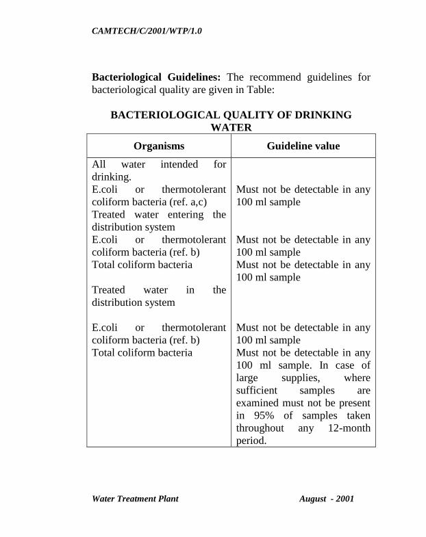
Bacteriological Guidelines: The recommend guidelines for
bacteriological quality are given in Table:
BACTERIOLOGICAL QUALITY OF DRINKING
WATER
Organisms Guideline value
All water intended for
drinking.
E.coli or thermotolerant
coliform bacteria (ref. a,c)
Treated water entering the
distribution system
E.coli or thermotolerant
coliform bacteria (ref. b)
Total coliform bacteria
Treated water in the
distribution system
E.coli or thermotolerant
coliform bacteria (ref. b)
Total coliform bacteria
Must not be detectable in any
100 ml sample
Must not be detectable in any
100 ml sample
Must not be detectable in any
100 ml sample
Must not be detectable in any
100 ml sample
Must not be detectable in any
100 ml sample. In case of
large supplies, where
sufficient samples are
examined must not be present
in 95% of samples taken
throughout any 12-month
period.

CAMTECH/C/2001/WTP/1.0
Water Treatment Plant August - 2001
Source: WHO guidelines for Drinking Water Quality Vol. 1 –
1993
a) Immediate investigative action must be taken if either
E.coli or total coliform bacteria are detected. The minimum
action in the case of total coliform bacteria is repeat
sampling these bacteria are detected in the repeat sample,
the cause must be determined by immediate further
investigation.
b) Although E.coli is the more precise indicator of faecal
pollution, the count of thermotolerant coliform bacteria is
an acceptable alternative. If necessary, proper confirmatory
test must be carried out. Total coliform bacteria are not
acceptable indicators of the sanitary quality of rural water
supplies, particularly in tropical areas where many bacteria
of no sanitary significance occur in almost all untreated
supplies.
c) It is recognises that, in the great majority of rural water
supplies in developing countries, faecal contamination is
widespread. Under these conditions, the national
surveillance agency should set medium term targets for
progressive improvement of water supplies, as
recommended in volume 3 of WHO guidelines for drinking
water quality 1993.
CAMTECH/C/2001/WTP/1.0
Water Treatment Plant August - 2001
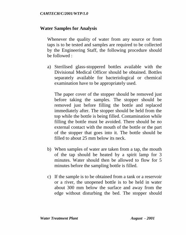
Water Samples for Analysis
Whenever the quality of water from any source or from
taps is to be tested and samples are required to be collected
by the Engineering Staff, the following procedure should
be followed :
a) Sterilised glass-stoppered bottles available with the
Divisional Medical Officer should be obtained. Bottles
separately available for bacteriological or chemical
examination have to be appropriately used.
The paper cover of the stopper should be removed just
before taking the samples. The stopper should be
removed just before filling the bottle and replaced
immediately after. The stopper should be held from the
top while the bottle is being filled. Contamination while
filling the bottle must be avoided. There should be no
external contact with the mouth of the bottle or the part
of the stopper that goes into it. The bottle should be
filled to about 25 mm below its neck.
b) When samples of water are taken from a tap, the mouth
of the tap should be heated by a spirit lamp for 3
minutes. Water should then be allowed to flow for 5
minutes before the sampling bottle is filled.
c) If the sample is to be obtained from a tank or a reservoir
or a river, the unopened bottle is to be held in water
about 300 mm below the surface and away from the
edge without disturbing the bed. The stopper should

CAMTECH/C/2001/WTP/1.0
Water Treatment Plant August - 2001
then be removed, the bottle withdrawn when full, a few
drops of water poured out and the stopper replaced and
tied down.
d) Well water should be collected by lowering the bottle
(tied with a piece of weight) into the well by a string
attached to the neck the stopper should be removed by
another string tied to it and the bottle filled in with
water, not from the surface but from a point a metre or
two above the bottom of the well. If collected from a
tube-well with a pump, the water should be allowed to
flow for about 20 minutes.
e) Bottles containing samples of water should be properly
labelled, packed around with ice and saw-dust and sent
without any delay to reach the Divisional Medical
Officer. Satisfactory packing and expeditious dispatch
are essential for proper bacteriological examination.
Method of Treatment
The aim of water treatment is to produce and maintain
water that is hygienically safe, clean and potable in an
economical manner. Treatment should ensure the desired
quality at the end points of consumption.
The method of treatment to be employed depends on the
nature of raw water and the desired standards of water
quality. The unit operations in water treatment constitute
aeration, flocculation (rapid and slow) and clarification,
filtration, disinfection, softening, deferrization,

CAMTECH/C/2001/WTP/1.0
Water Treatment Plant August - 2001
defluoridation and water conditioning. Different
combinations are possible to achieve the required quality of
water. The choice of any particular sequence of treatment
will depend not only on the quality of the raw water
available but also on the comparative economics of
alternative treatment steps to get desired quality.
In case of ground water storage which are well protected,
where the water has turbidity below 10 NTU and water is
free from odour and colour, plain disinfection by
chlorination is adopted before supply.
Where ground water contains excessive iron, dissolved
carbon dioxide and odorous gases, aeration followed by
flocculation and sedimentation, rapid gravity or pressure
filtration and disinfection may be necessary.
Conventional treatment including pre-chlorination,
aeration, flocculation and sedimentation, rapid gravity
filtration and post chlorination are adopted for highly
polluted surface waters laden with algae or other micro
organisms.
Water with excessive hardness will need softening by
conventional method or by ion exchange method.
Disinfection of water
Water treatment processes described in paragraph above
remove micro-organism to varying degrees. For utmost
safety of water for drinking purposes, disinfection of water

CAMTECH/C/2001/WTP/1.0
Water Treatment Plant August - 2001
has to be done to remove disease-producing organisms
before it enters distribution system. Disinfection is also
required to prevent contamination of water during its transit
from the treatment plant to the place of its consumption.
The efficiency of disinfection depends on the nature of
disinfectants. For treatment on larger scale, chlorination is
generally used as treatment for disinfection. Chlorine can
be applied in water by using bleaching powder,
chloramines or as free chlorine gas. A minimum of 30 to 60
minutes contact time must be provided before delivery of
water to the consumer.
Sufficient number of chlorinators in working conditions
should be available with the Inspector of Works. To decide
the quantity of chlorine to be added, Inspector of works
should find out breakpoint chlorination and accordingly
chlorinate the supply.
Disinfection through chlorine
Disinfection is an important unit operation in a water
treatment practice. This process is brought about by
addition of chlorine either in the form of gas or bleaching
powder to the water body. In a water treatment plant, this
chlorination is effected n two stages (i) prechlorination (ii)
post chlorination. Prechlorination is done to reduce the
algal population, which may otherwise hinder the process
of coagulation and filtration.
Post chlorination is recommended on the filtered water to
make it suitable for human consumption.

CAMTECH/C/2001/WTP/1.0
Water Treatment Plant August - 2001
Chlorine acts as a disinfectant by the :
a) Destruction of micro-organisms
b) Oxidation of Fe, Mn, H2S
c) Removal of taste and odour producing compounds
d) Oxidation of organic compounds by producing chloro-
derivatives.
For effective chlorination in water treatment practice it is
necessary to ascertain (a) dose of chlorine required (b)
optimum contact period and (c) the presence of residual
chlorine (.3 to .5 mg/l). from experience it has been found
that a contact period of 30 minutes is adequate to disinfect
water.
When chlorine is added to water, very quick hydrolysis
takes place as follows :
Cl2 + H2O - HOCl + HCl
Hypochlorous acid is very unstable and HOCl ionises to
HOCl - H+ + OCl
-
The equilibrium in Cl2, HOCL, OCl- is dependent on pH of
water and HOCl, OCl-
forms are known as free residual
available chlorine. At pH around 2 - Cl2 ; 2.5 – 7 pH HOCl;
and at pH 8.5 and above entirely OCl- exists.

CAMTECH/C/2001/WTP/1.0
Water Treatment Plant August - 2001
Beyond a certain stage, any added chlorine, remains in the
form of free residual chlorine. This point is known as break
point. At his point all pollutants are destroyed and free residual
chlorine starts forming.
The existence of residual chlorine in treated water, therefore,
provided indication of the water being free from any organic
impurities and also safe from aquatic and bacteriological
contamination.
Chlorine demand
Chlorine and chlorine compounds by virtue of their oxidising
powder can be consumed by a variety of inorganic and organic
materials present in water before any disinfection is achieved.
It is, therefore, essential to provide sufficient time and dose of
chlorine to satisfy the various chemical reactions and leave
some amount of unreacted chlorine as residual either in the
form of free or combined chlorine adequate for killing the
pathogenic organisms.
The difference between the amount of chlorine added to water
and the amount of residual chlorine after a specified contact
period is defined as the chlorine demand. The chlorine
demand of any given water varies with the amount of chlorine
applied, the time of the contact, pH, temperature, and type and
quality of residual desired.

CAMTECH/C/2001/WTP/1.0
Water Treatment Plant August - 2001
Estimation of chlorine
The usual tests practised for estimating the residual chlorine in
water are the orthotoulidine test (OT) and orthotoulidine
arsenite test (OTA), the former used for total residual chlorine
concentration and the latter for free available chlorine. When
orthotoulidine reagent is added to water containing chlorine; a
greenish yellow colour develops, the intensity of, which is
proportional to the amount of residual chlorine present. Soluble
tablets of DPD (diethylphenylene-diamine) have also been
used satisfactorily in place of orthotoulidine reagent.
Residual Chlorine
General
The residual chlorine is estimated to assess whether the water
is satisfied to its chlorine demand or not. The existence of
residual chlorine indicates that the water is safe from reducing
and organic substances and also that the harmful aquatic and
bacteriological masses have been properly disinfected. Min.
residual chlorine available at the farthest end shall be 0.2 mg/l.
During monsoon months or if specific complaints are there,
super-chlorination more than 2 PPM of chlorine may be
resorted to effectively get rid of bacteria.
Principle
Orthotolidine method is recommended as the most easiest and
applicable method for the estimation of residual chlorine
Orthotolidine produces yellow coloured compound with
CAMTECH/C/2001/WTP/1.0
Water Treatment Plant August - 2001
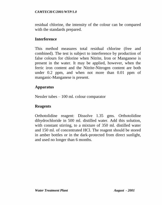
residual chlorine, the intensity of the colour can be compared
with the standards prepared.
Interference
This method measures total residual chlorine (free and
combined). The test is subject to interference by production of
false colours for chlorine when Nitrite, Iron or Manganese is
present in the water. It may be applied, however, when the
ferric iron content and the Nitrite-Nitrogen content are both
under 0.2 ppm, and when not more than 0.01 ppm of
manganic-Manganese is present.
Apparatus
Nessler tubes – 100 ml. colour comparator
Reagents
Orthotolidine reagent: Dissolve 1.35 gms. Orthotolidine
dihydrochloride in 500 ml. distilled water. Add this solution,
with constant stirring, to a mixture of 350 ml. distilled water
and 150 ml. of concentrated HCl. The reagent should be stored
in amber bottles or in the dark-protected from direct sunlight,
and used no longer than 6 months.
CAMTECH/C/2001/WTP/1.0
Water Treatment Plant August - 2001
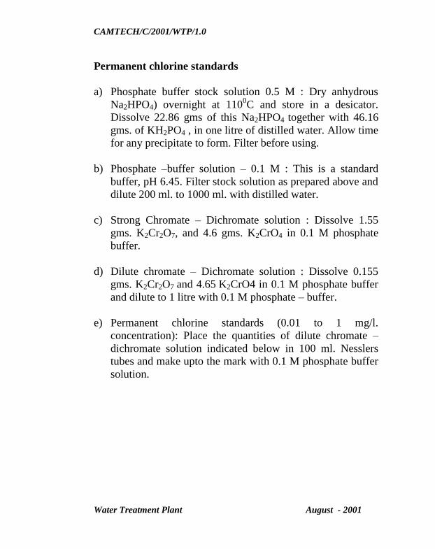
Permanent chlorine standards
a) Phosphate buffer stock solution 0.5 M : Dry anhydrous
Na2HPO4) overnight at 1100C and store in a desicator.
Dissolve 22.86 gms of this Na2HPO4 together with 46.16
gms. of KH2PO4 , in one litre of distilled water. Allow time
for any precipitate to form. Filter before using.
b) Phosphate –buffer solution – 0.1 M : This is a standard
buffer, pH 6.45. Filter stock solution as prepared above and
dilute 200 ml. to 1000 ml. with distilled water.
c) Strong Chromate – Dichromate solution : Dissolve 1.55
gms. K2Cr2O7, and 4.6 gms. K2CrO4 in 0.1 M phosphate
buffer.
d) Dilute chromate – Dichromate solution : Dissolve 0.155
gms. K2Cr2O7 and 4.65 K2CrO4 in 0.1 M phosphate buffer
and dilute to 1 litre with 0.1 M phosphate – buffer.
e) Permanent chlorine standards (0.01 to 1 mg/l.
concentration): Place the quantities of dilute chromate –
dichromate solution indicated below in 100 ml. Nesslers
tubes and make upto the mark with 0.1 M phosphate buffer
solution.

CAMTECH/C/2001/WTP/1.0
Water Treatment Plant August - 2001
CHLORINE STANDARDS
(0.01 to 1.0 mg./l)
Chlorine
Mg./l
Chromate –
dichromate
solution (ml.)
Chlorine
Mg./l
Chromate –
dichromate
solution
(ml.)
0.01 1 0.3 30
0.02 2 0.35 35
0.05 5 0.45 4
0.07 7 0.6 60
0.1 10 0.7 70
0.15 15 0.8 80
0.20 20 0.9 90
0.25 25 1.0 100
Procedure
Use 0.5 ml. orthotoulidine reagent for 10 ml. sample, 5 ml. for
100 ml. sample and the same ration for higher volumes. Place
orthotoulidine reagent in the Nessler tube or other container,
add sample to the proper mark or volume, mix rapidly, and
allow standing for 5 minutes. Compare the colour developed,
against the standards.
*** GO TO INDEX

CAMTECH/C/2001/WTP/1.0
Water Treatment Plant August - 2001
CHAPTER – 3
OPERATION & MAINTENANCE OF
WATER TREATMENT PLANT
Requirements
Maintenance should be carried out in a manner, which prevents
emergencies and unscheduled shutdowns. An efficient
maintenance requires considerable skill, which can only be
acquired experience, study and practice. Basically, any
maintenance programme should observe the following general
rules:
a) Keep a set of plans giving details of the several units and
indicating the layout and position of all pipelines and
appurtenances;
b) Establish a systematic plan of daily operations;
c) Establish a routine schedule for inspection of machinery
and lubrication and maintain records thereof. Instructions
for lubrication, the type of lubricant suggested and the
frequency of lubrication should be drawn;
d) Main data and record of each piece of equipment giving
details of cleaning and faulty operating conditions. Details
for any special equipment should be obtained from the
manufacturers;
CAMTECH/C/2001/WTP/1.0
Water Treatment Plant August - 2001
e) Keep a record of analysis of water collected at various
points from the source to the distribution system and
observation on the effect of such quality on the several
units of operation ; and
f) List out safety measures including good housekeeping.
General Maintenance
The backbone of the successful plants is the regular preventive
maintenance by the operating staff. The following are the
general points to be noted for the maintenance. Besides, the
instructions are outlined for important operative equipment in
the manufacturer’s instruction manuals.
Oil levels are to be checked and the deficit level is to be made
up by using the recommended grade of oil.
Reduction gears.
Oil lubricated pumps (if any).
The frequency of application and type of lubricant to be used is
to be followed as per the manufacturer’s instruction manual.
The major greasing points to be checked once in a week are
listed below:
Plumber Blocks
MS shutter sides
Handwheel operated spindles/valves.
CAMTECH/C/2001/WTP/1.0
Water Treatment Plant August - 2001
The sprocket and chain drive for Clarifier.
Clarifier central bearing.
Motors
Recommended grade of grease:
Shell Retiflux – A
Mobilax – 3
Multipurpose grease – 3
Some hand-operated shutters, which are not in regular use,
should be operated from time to time for easy movement and
prevention of failure when required to be put into service.
The carbon brushes of the current collector box should be
checked for abrasion and wear every three months and replaced
when worn out, with brushes suitable for use in slip ring
(5 rings) induction motor.
‘V’ belt drives, couplings should be checked for tension and
alignment and adjusts periodically, if necessary.
The common problems encountered in water treatment
plants are:
Raw Water
The problem will mainly relate to the change in the quality of
the raw water due to natural causes and by adverting pollution
of the source.

CAMTECH/C/2001/WTP/1.0
Water Treatment Plant August - 2001
In the case of river source, a sanitary survey of the catchment
area should be undertaken at regular intervals and water
samples taken at significant points where pollution is likely to
take place. The analysis of these samples will reveal the degree
and nature of pollution and thus help in taking the necessary
measures to check or control the pollution. If the fluctuations in
quality are rapid, the surveys should be undertaken at shorter
intervals. Turbidity is not a special problem as the dosage of
the coagulant is adjusted on a daily routine. On the other hand
a sudden rise in chlorides content will indicate pollution most
probably due to sewage. In such cases, more confirmatory test
should be undertaken such as for nitrogen in its various forms,
dissolved oxygen absorbed and chlorine demand to help the
operator whether pollution has taken place and to fix the dose
of prechlorination needed.
In the case of a lake as a source the periodical biological and
physical examination of the samples will indicate if there is any
need for control of algae which may lead to taste and odour
problems or clogging of filters. Samples taken at different
depths in the lake will indicate the level at which water should
be drawn to get the best quality of water.
1) Flow Measuring Devices
Float sump should be periodically cleaned so see that silt does
not accumulate which may affect the proper functioning of the
float. Charts and pen recorders should be stocked adequately.
Annual or more frequent calibration of these devices is
necessary. Annual servicing and checking of the instruments is
imperative.
CAMTECH/C/2001/WTP/1.0
Water Treatment Plant August - 2001
2) Chemical feeding unit
Alum preparation tank is to be painted annually by anti
corrosive paint. V-notch weirs and floats and floating
arrangements should be cleaned daily. Enough spares for the
mixing device in the chemical preparation should be stocked.
Setting of the V-notch should be checked periodically.
Sometimes, if the alum dosing equipment is not in order, the
alum slabs are just dumped in the raw water channel. This is
bad practice and should not be adopted as it will mean wastage
of alum and improve dosing of alum. Alum should be made
into a solution and dispensed until the dosing equipment is
rectified. The optimum dosing of alum and coagulant aids
should be based on a proper and detailed laboratory study
including Jar Test. The chemical feeding rate should be
controlled, depending upon the needs from time to time.
3) Rapid Mixer
Adequate spares should be kept ready in stock for timely
replacement when necessary. Periodical painting with
anticorrosive paints could prolong life of the equipment.
4) Slow Mixer
Slow Mixer should be operated continuously for avoiding
sludge built-up. All equipment should be painted with anti-
corrosive paints every year. Mechanical devices should be
properly lubricated and worn out parts replaced. In non-
CAMTECH/C/2001/WTP/1.0
Water Treatment Plant August - 2001
mechanical type of flocculators like baffle and tangential flow
tanks. Desludging atleast once in six months is necessary.
5) Aerators
Aerators are required to be maintained in a clean condition so
that maximum water surface and agitation are provided.
Slime and algae growth on the surface would require cleaning
and periodic treatment with copper sulphate with or without
lime to kill growth. The porous or tubes used with diffusion
aerators may become partly clogged either from dust in the
compressed air or from the collection of sediment on the
outside surfaces. When Aerators are shutdown, appropriate
cleaning with detergents or acid brush should be attempted.
Clogging of diffuser plates could be minimised by
i. maintaining air filters in effective operation
ii. not over-lubricating air compressors and blowers
iii. maintaining air pressure on diffusers when compressors
are shut down.
6) Clarifier or Sedimentation Tank
Annual overhauling and repainting of the unit should be done a
month or two prior to monsoon.
Sludge lines should be kept free of chokages. The lines should
be flushed with high-pressure water if chokages are noticed.
The telescopic sludge discharge device, when provided, should
CAMTECH/C/2001/WTP/1.0
Water Treatment Plant August - 2001
be checked for free vertical movement and O-rings replaced
when leaky.
The traction wheels should be checked for alignment and
rubber wheels replaced, if required.
The unit should be worked continuously to protect the
mechanical parts from ill effects of corrosion, malfunctioning
etc., as well as problems from sludge built-up. Outlet weirs
should be kept cleaned at all times. Algaecide or bleaching
powder may be used for controlling biological growth or weirs.
i) Important features in the operation of Clarifier are:
a) The introduction of water into the tank with a minimum
turbulence;
b) The prevention of short circuiting between inlet and
outlet; and
c) The removal of the effluent with the minimum of
disturbance to avoid settled material being carried out
of the tank.
Very often, a basin which is not functioning properly can be
modified by making changes to the inlet and outlet devices by
installing stilling baffles so as to improve any or all of the
important features mentioned above. Algal growth, if any
should be controlled.
CAMTECH/C/2001/WTP/1.0
Water Treatment Plant August - 2001
ii) Algal growth
During summer season, reasonably higher quantities of algal
species are reported in the river water. Stagnant water is also
liable to have algal growth. The intensity of algal growth
depends upon the type of algal species, the prevailing nutrient
conditions and other physio-chemical characteristics of water.
The major species of trouble causing algae can be identified
with aid microscope. Algae impart colour, odour and
anaesthetic taste to the water body. Adequate pre-chlorination
effectively curbs the algal nuisance. Besides chlorination,
application of copper sulphate and potassium permanganate
have also been found to be effective. Before conducting the
chemical treatment for algal destruction, it is necessary to
ascertain ‘chlorine demand’ and oxygen absorbed at 370 for 4
hours, of the water for the optimum implementation of the
chemical dosage without affecting the performance of the
proceeding treatment units. The pre-chlorinated water should
not contain residual chlorine since excess of residual chlorine
partially retards the efficiency of the chemical treatment during
coagulation process.
7) Rapid Gravity Filters
a) Deflection gauge: Rate of flow gauges and loss of head
gauges frequently get out of order. The operator should
be conversant with the working of gauges and should be
able to handle minor repairs. Necessary spares should
be stocked.

CAMTECH/C/2001/WTP/1.0
Water Treatment Plant August - 2001
However, even if the rate of filtration gauge is under
repairs, the filtration rate can be checked whenever
desired by closing the inlet valve and observing the
time during which the level of water in the filter falls by
measured distance.
For knowing the loss of head when the gauges are out
of operation, a temporary arrangement consisting of
two glass tubes on each side of a calibrated scale could
be provided. One tube is to be connected to the effluent
pipe between filter and controller and the other tube to
the filter structure above the sand. The relative
elevation of the water surfaces in these tubes indicates
the prevailing hydraulic gradient or loss of head
through the filter.
b) Slime growth: When slime growths are noticed on
filters, the bed is cleared in the normal way and the
water is lowered to the level of the sand bed. Then
common salt is distributed evenly over the surface of
the sand, using 7kg/m2 of filter area, after which the
wash water valve is opened until water rises above 15
cm above the sand level. The water is allowed to remain
for 2 hours to dissolve the salt and then lowered to the
bed level to be retained for 24 hours after which it is
thoroughly back washed before placing into service. If
this procedure does not produce effective results, it may
be necessary to replace the media.
c) Backwash requirements: The waste water drains
carrying filter back wash water is led away quickly,

CAMTECH/C/2001/WTP/1.0
Water Treatment Plant August - 2001
there will be no backing up in water channel or into the
filter bed. Incidentally, it may be worthwhile to
consider setting up a plain sedimentation tank to
recover the supernatant from the backwash water. For
the small investment, the water recovery could be
appreciable.
The requisite upflow velocity of backwash water should
be maintained at the design rate for proper cleaning of
the sand. The practice of backwash at reduced rate for
longer periods should be avoided as it leads to wastage
of water and washing becoming ineffective.
Backwashing of filters should not be based on
arbitrarily fixed time schedules but the frequency
should be in accordance with the filtrate quality and
head loss measurement. Duration should be dependent
upon the turbidity of the wastewater.
d) Mud ball formation of filter beds:
With deficient washing gelatinous material on the sand
grains are not washed off. They accumulate and
agglomerate to form ‘Mud Balls’ in the initial stages,
after back washing, the mud balls being lighter are
deposited on the media and are seen easily. Unchecked
formation of mud balls will eventually result in large
balls sinking through the agitated sand during the
washing process and then collecting between gravel and
sand this will cause clogging of gravel which will:

CAMTECH/C/2001/WTP/1.0
Water Treatment Plant August - 2001
a) Reducing efficiency of filter beds.
b) Uneven distribution of wash water and thereby sand
in free area.
c) Formation of jets during washing which dislodges
the gravel and the gradation of filter media is no
longer level.
By proper coagulation and settling of applied water,
mud-ball formation could be considerably reduced.
Surface wash, or surface raking, or shovelling at
intervals helps reduce mud ball formation. Also
compressed air scouring during backwash for periods of
three minutes, instead of 1 to 2 minutes, effectively
decreases mud-ball concentration.
e) Crack in sand beds:
The existence of cracks in sand under water indicates
that the sand grains are being cemented together by
some material in the applied water. Organic matter, fine
clay, oil and the very gelatinous floc formed at times
when micro-organisms are coagulated or developed in
the beds have been found to cement the sand grains and
this causes shrinkage of sand bed. This causes cracks
and is most likely to occur at the filter walls and the
sand is drawn away from the walls.
The gelatinous film on the sand grain may be removed
by treatment with alkali or chlorine.

CAMTECH/C/2001/WTP/1.0
Water Treatment Plant August - 2001
a) Wash the bed thoroughly as possible and have water
above the sand upto slightly lower level than the
trough.
b) Dissolve 5-10 kgs. of caustic soda in this water for
each square meter of filter area.
c) Filter until the water level reduces almost upto 1"
above the same.
d) Allow to act for 6-12 hours.
e) Wash the bed thoroughly.
Similar procedure may be followed for the treatment
with chlorine also but use 0.2 kg. of calcium
hypochlorite per sq. m. filter area and let the solution
act for 12-24 hours, before washing.
If algae infested water is applied on sand,
alkali/chlorine treatment as enumerated above clogs the
media.
f) Air binding in filter beds:
Air binding is caused due to the accumulation of air in
the filter bed and under drains. The trouble occurs
during the winter season when the dissolved air content
of the water is at maximum or due to operation of filter
under ‘negative head’.

CAMTECH/C/2001/WTP/1.0
Water Treatment Plant August - 2001
Shutting off the filter for a few minutes to eliminate the
negative head or washing the filter for 1 or 2 minutes
would remedy the situation by releasing the retained air
in the system. Air binding would materially reduce the
rate of filtration or impair the filtrate gravity.
g) Bumping of filter beds:
Sometimes careless and indifferent operation may lead
to ‘bumping’ or ‘lifting’ of the filter beds when
switching on the back-wash for a minutes to dislodge
the sand bed and recommencing filtration without going
through the full backwash cycle is adopted. This
practice should be discouraged as the filtrate quality
deteriorates considerably.
h) Inadequate media on the filter bed:
Expansion of sand bed during Backwashing should be
kept within the limits to avoid carry over the sand to
wash water through which would lead to appreciable
depletion of sand depth over a period of time. Sand
depth should never be depleted by more than 10 cm.
after which the media has to be replenished. The entire
bed should be taken out and additional sand mixed to
give the required effective size and uniformity
coefficient. Before starting the filter, the sand has to be
backwashed to stratify the bed.

CAMTECH/C/2001/WTP/1.0
Water Treatment Plant August - 2001
i) Defective Gauges:
Rate of flow gauges and loss of head gauges frequently
get out of order. The operator should be conversant
with the working of the gauges and should be able to
handle minor repairs. Necessary spares should be
stocked.
However, even if the rate of filtration gauge is under
repair, the filtration rate can be checked whenever
desired by closing the inlet valve and observing the
time during which the level of water in the filter falls by
a measured distance.
For knowing the loss of head when the gauges are out
of operation, a stop gap arrangement consisting of two
glass tubes on each side of calibrated scale could be
provided. One tube is to be connected to the effluent
pipe between filter and rate controller and the other
elevation of the water surfaces in these tubes indicates
the prevailing hydraulic gradient or loss of head
through the filter.
8) Problems related to the quality & flow pattern:
When flow gets reduced, it may be desirable to cutout certain
units but it is preferable to operate all the units with reduced
flow conditions. In any case, the flow through condition in the
several units should be periodically studied using appropriate
tracers. This will help to locate if there is any short-circuiting
so that corrective measure can be adopted.
CAMTECH/C/2001/WTP/1.0
Water Treatment Plant August - 2001
The flow condition in open channels should be examined
periodically to avoid obstructions and heading up which will
affect the unit process especially the efficiency of the
clarification unit.
9) Sludge carry over from clariflocculator:
Sometimes it is observed that the chemical flocs are carried
over alongwith the clariflocculator effluent. This may happen
due to heavy accumulation of sludge in the clariflocculator
resulted from improper desludging. Periodic and proper sludge
withdrawal is recommended as a remedy.
During lean periods, when the turbidity of raw water is very
low, the phenomenon of sludge carry over in clariflocculator
has been observed. In such cases addition of weighting agents
like Fuller’s earth, calcite etc. or re-circulation of settled sludge
solve the problem.
Excessive addition of chemicals used for coagulation or else
imbalance addition of chemical also tends to add to the sludge
carry over in clariflocculator. To avoid this performance of Jar
Test dosing of chemical accordingly has to be done for the
proper functioning of the plant.

CAMTECH/C/2001/WTP/1.0
Water Treatment Plant August - 2001
10) Master balancing reservoirs and elevated reservoirs
Important aspects to be considered during
maintenance are :
i. Measurement of inflows and outflows : Whenever
measuring devices are provided, it should be seen that
discharge at inlets fairly tallies. It should be seen that
water level indicators and recorders are in proper
working order.
ii. Structural Leakage: A structural damages and leakage
should be promptly repaired.
iii. Preventing External Pollution: The manhole opening
ventilating shafts and overflow pipes should be
properly closed and protected with wire gauge from
external pollution.
iv. General cleanliness in the around the reservoir should
be maintained and observed. A garden around the
reservoir structure may be provided.
v. A programme for periodical cleaning of the reservoirs
atleast once in a year should be undertaken. During
such cleaning process there should be facility to bye
pass the supply to distribution system.
vi. Appropriate safety measures to prevent climbing of
unauthorised persons should be provided. All the
railings provided shall be maintained in a safe and firm
condition.
CAMTECH/C/2001/WTP/1.0
Water Treatment Plant August - 2001
Start up Preparation
Check and ensure that the pump sets, motors valves, piping
etc. are secured and in proper alignment.
Remove all construction materials and tools lying in and
around units.
Ensure that the drainage is in working condition.
Fill up the bearings, gearboxes and the moving parts with
the correct grade and quantity of lubricants.
Turn unit by hand to ensure free movement of pump and
drive shafts.
Ensure that the power supply is sufficient to run all the
equipment at full load.
Ensure that the correct grades of chemical are available in
ready stock at least for one month.
CAMTECH/C/2001/WTP/1.0
Water Treatment Plant August - 2001
Shut down
The following procedure is recommended to be adopted when
the plant needs to have a shut down.
a) Out of raw water supply and additional of chemicals to the
respective points.
b) Withdraw the settled sludge completely from the
clariflocculator and then stop the bridge and flocculating
paddles.
c) If the shut down is planned for 24 hours, the mixing
arrangements in chemical preparation tanks should be kept
on the entire period. On the increase of the duration of shut
down, these may be kept stopped and should be restarted
atleast six hours before the start up of the plant for
achieving a homogeneous solution slurry.
d) Backwash the filter beds as procedure mentioned in filters
operation and keep it ready for restart.
e) Agitators in flash mixer are to be stopped.
f) All pumps are to be stopped.
CAMTECH/C/2001/WTP/1.0
Water Treatment Plant August - 2001
Safety
General
In the operation of any plant safety of personnel and equipment
is an important consideration. Precautionary measures for
personnel working near rotating machinery or at a higher
elevation etc., are common for any plant and hence, they are
not elaborated here. Handling of chemicals only needs special
mention.
i) Hydrated Lime
Lime is supplied as a very fine powder of the order of 100-
mesh size. Handling this chemical hence gives dust nuisance.
Use safety goggles, gas mask, gloves, apron and boots.
ii) Alum
Alum is commonly available in the form of blocks, which
needs to be made into pieces for quick dissolution. Because of
Hygroscopic characteristics, alum and its solution cause
irritation on skin. Rubber aprons, gloves, boots and safety
goggles are recommended for use while handling the alum.
iii) Chlorine
Chlorine vapour is extremely hazardous to human health. On
leakage, avoid prolonged or repeated breathing inside the
chlorinator room. Suitable gas mask may be used while
handling chlorinator unit.

CAMTECH/C/2001/WTP/1.0
Water Treatment Plant August - 2001
iv) Coagulants
Handling
1. Ordinarily a plant labourer can handle 50-kg container
when aided by small handcart. Heavy container should
be handled with the aid of mechanical contrivance such
as trucks, monorails, cranes and other special
equipment.
2. Rolling of cylinders, barrels, drums on the floor should
be avoided.
3. Iron salts generally require more careful handling as
compared to alum salts.
4. While laying electrical wiring and fixtures adequate
safety precautions should be observed during their
installation for ensuring safe use of electricity.
5. Use of mechanical lifting devices should be preferred.
Storage
1. The coagulant store should be suitably located to
prevent entry of water. Where coagulants are purchased
in bags, storage by piling on the floor of the storeroom
shall be suitably located at a convenient level.

CAMTECH/C/2001/WTP/1.0
Water Treatment Plant August - 2001
2. In case when coagulants are purchased in blocks, the
height of stack is generally limited up to 3 m for non-
operational stacks and 1.5 m for operational stacks.
3. Coagulants should be stored in a damp-proof storage
room.
4. Hygroscopic coagulant should be packed in moisture-
proof container.
5. All plants, particularly small ones should keep on hand
at all times the supply of coagulants sufficient to
provide a safety factor. A storage of 3 months based on
average consumption is advisable. Special
consideration should be given to requirements of the
monsoon season. But this again depends upon the type
and form of coagulant, location of the plant, source of
supply, transport facilities and the arrangement made
with the suppliers.
6. In case where the major storage is provided at a place
away from the feeding device a week’s storage space
should be provided near the coagulants feeding device
to facilitate handling. Special precautions against
flooding should be taken.
7. The floor of the storage room should be given anti-
corrosive treatment. Similar treatment should also be
given to side walls and intervening columns, upto a
minimum height of 3 m above the floor level.

CAMTECH/C/2001/WTP/1.0
Water Treatment Plant August - 2001
8. A working space of minimum 30 % of floor area should
be provided so that all stacked coagulants are easily
accessible.
Weighing
1. It is necessary that predetermined quantity of
coagulants is used for preparing the solutions.
Arrangements of weighing of coagulants both when the
consignments are received as well as before feeding it
into the equipment should be provided.
2. Depending upon the quality of the coagulant,
appropriate weighing machine conforming to IS may be
used.
Solution tanks
Number of tanks
There should be three dosing tanks. For avoiding the
interruption in dosing, one of them would be for
preparation, other for dosing and the third as a stand by (for
being got ready for receiving coagulants after cleaning).
However, when the coagulant solution is to be used at the
rate of 5000 litres per 24 hours or less, the number of
solution tanks can be restricted to 2, each tank to hold
solution for 24 hours. When the quantity of coagulants used
is large, more than one tank may be used to meet 8 hours
dose.

CAMTECH/C/2001/WTP/1.0
Water Treatment Plant August - 2001
Level Indicators
Level indicators shall be installed in the solution tanks to
know the quantity remaining in the tank at any given
instant. The level indicator should be such that they are not
affected by the agitation of liquid in the tank.
Preparation of coagulant solution
Mixing Devices
It is essential to ensure homogeneity of the prepared
coagulants solution. Proper mixing may be done by the
following methods.
Mechanical Agitation
The normal turnover capacity of the agitators for the alum
solution tank should be 2 hours.
Compressed Air
Agitation by compressed air is particularly economical for
large size tanks and also when number of tanks is more
than four.
Air supply should be 0.1 to 0.15 m3/minute per m
3 of
effective liquid capacity of solution tank. The pressure of
air supply will depend upon depth of liquid and losses
through distribution pipe and orifice holes. High density
polyethylene, unplasticized PVC or polypropylene pipe
CAMTECH/C/2001/WTP/1.0
Water Treatment Plant August - 2001
should be used as distribution pipe inside the tank at a level
300 to 350 mm above tank bottom.
Air agitation need not be continuous. Five minutes
agitation followed by 20 to 30 minutes of rest is sufficient
to keep the solution homogeneous.
Re-circulating solution
When re-circulation pumps are provided the capacity
should be sufficient to turn over the tanks content in 2
hours.
Water for preparing Coagulants
Whenever filters are installed filtered water should be used
for making chemical solutions. In absence of filters or in
industrial water treatment plant settled clear water may be
used.
v) Chlorination equipment and container room
Installation
1) Chlorine gas units and cylinders shall be housed in
separate rooms, easily accessible, close to the point of
application and convenient for truck loading and safe
container handling. The floor shall be flat and at least
150 mm above the surrounding ground and drainage
shall be adequate. The height of the container room
should be at least 4.0 m. under no circumstances such

CAMTECH/C/2001/WTP/1.0
Water Treatment Plant August - 2001
units shall be housed in basement or below ground level
since the chlorine gas is heavy and settles into
depressions.
2) The exits shall lead directly out in the open and the
doors shall open outward. The hinges of the doors
should be parliamentary types. At least two exits shall
be provided in each such room.
3) Adequate arrangements for air circulation and cross
ventilation shall be made in the rooms. Air entry shall
be from above and air exit shall be from below. Exhaust
fans shall be provided at floor level.
4) Rooms for chlorine containers in which more than 200
kg chlorine is stored shall be separated from the
chlorine gas apparatus rooms and shall be accessible
only from outside.
5) Containers shall rest securely on cradles or on a level
rack equipped with adequate safety block to prevent
rolling and be slightly elevated from the floor to keep
them dry.
6) The temperature in the installation room shall be within
the range of +4 to +400C. The chlorine gas containers
and chlorine gas pipes shall not be exposed to direct
heat radiation and shall be protected from sunrays.
7) Electrical installations inside the chlorine gas rooms
shall be limited to the absolute minimum required.

CAMTECH/C/2001/WTP/1.0
Water Treatment Plant August - 2001
While laying electrical wiring and fixtures adequate
safety precautions shall be observed during their
installation of ensuring safe use of electricity. Note:
Rigid PVC conduits should be preferred.
8) The following information shall be indicated
prominently on the outside entry door:
“Chlorine gas dosing apparatus room”
“Smoking and handling naked flame prohibited”.
“Admission restricted”.
Handling
1) Ordinarily a plant labourer can handle up to 100 kg.
cylinder when aided by small handcart. Heavy
containers shall be handled with the aid of mechanical
contrivance, such as trucks, monorails, cranes or other
such equipment.
2) Chlorine gas container shall not be bumped, dropped or
rolled on the ground and no object shall be allowed to
strike them with force.
3) Use of mechanical lifting devices is recommended. For
lifting one tonne container, the capacity of the
mechanical device should be about 2 tonnes.

CAMTECH/C/2001/WTP/1.0
Water Treatment Plant August - 2001
Storage
1) All plants, particularly small ones, should keep on hand
at all times sufficient supply of chlorine cylinders or
drums.
2) Special consideration shall be given to requirements of
monsoon seasons.
3) Cylinder shall confirm to IS: 7681-1975 and the
provisions of IS:8198 (Part 6)-1979 for filling
inspection, testing, maintenance and use of containers
for storage and transportation of liquefied chlorine in
cylinders shall be observed.
4) Cylinders shall be stored vertically so that a leaking
container, if found, can be removed with the least
possible handling of others. Tonne containers shall be
stored on the sides all the time horizontally with
suitable rollers or saddles.
5) Tonne containers are equipped with two valves each
with an internal eduction pipe. A removable hood is
provided to protect the valves from injury during
shipment and handling. In placing tonne containers in
position for use, the two valves shall be in vertical
alignment. The eduction pipes then permit the upper
valve to discharge gas and the lower valve liquid
chlorine.

CAMTECH/C/2001/WTP/1.0
Water Treatment Plant August - 2001
6) No other objects except chlorine gas storing containers
shall be kept in the room.
Safety
1) All operating and storing rooms for chlorine gas
appliances and containers shall be fire proof.
2) Chlorine storage rooms should preferably be provided
with chlorine gas alarm device which gives out an
acoustic or an optical signal when the chlorine gas
concentration is reached, the set value for which is 1.0
mg chlorine per cubic metre of air in case of a person
working in the room and 20 mg chlorine per cubic
metre of air when no human being is inside the room.
3) The sensor for alarm device shall be placed not higher
than 300 mm above the floors of the room.
4) A bottle of ammonia is essential to detect leaks, etc., in
case alarm device is not provided.
5) Cylinder as well as chlorine shall be tested at every
shift period for leaks, first by trying to detect the sharp
irritating smell of chlorine, then by passing over each
cylinder and around each valve and pipe connections, a
rod with a small cotton-wool swab tied on the end,
dipped in an aqueous solution of ammonia. If chlorine
is present in the air, the swab will appear to smoke due
to formation of white cloud of ammonium chlorine. If
the leak appears to be heavy, all persons not directly

CAMTECH/C/2001/WTP/1.0
Water Treatment Plant August - 2001
concerned should leave the area and the operator should
put on his mask and make a thorough search of the leak.
Note: In tracing a leak, always work down-stream that
is start at the cylinder and work down along the line of
flow until the leak is found.
a) Safety equipment, like gas masks, rubber gloves, aprons
shall be housed in easily accessible (unlocked)
cupboard placed outside the chlorination room.
Note: Faulty gas mask is worse than none at all. Hence
these shall be tested frequently and canisters shall be
changed at proper intervals.
b) First aid box and eye wash fountain shall be provided
outside chlorinator room.
c) The provisions shall be made for emergency disposal of
chlorine from leaking containers. The proportions of
alkali and water recommended for this purpose are
given in Table 1.

CAMTECH/C/2001/WTP/1.0
Water Treatment Plant August - 2001
Table – 1
Container
capacity
Kg.
Caustic soda Soda ash Hydrated lime
100%
Kg.
Water
L
100%
Kg.
Water
L
100%
Kg.
Water
L
45 57 180 136 450 57 570
67 85 275 204 680 85 850
1000 115 3640 2272 9090 115 1150
Note: When chlorine is to be absorbed in hydrated lime, the
solution should be continuously and vigorously agitated.
d) Water shall never be applied to the chlorine leak to stop
it, as it will only make it worse.
e) When a chlorine leak occurs, the ventilation system
should be operated immediately before any person
enters the chlorination room.
Note: Ventilation system should be controlled from
outside.
f) The exhaust pipe of the apparatus shall lead to the open
through the shortest path and the outlet of this exhaust
pipe shall not be readily accessible.
g) In case of fire, the cylinders and drums containing
chlorine shall be protected by spraying with water since
the containers can burst at temperatures of over 700C.
Source of pressurised water shall be provided adjacent
to the chlorination room.
CAMTECH/C/2001/WTP/1.0
Water Treatment Plant August - 2001
h) Before disconnecting the flexible leads from containers
to gas headers, the cylinder valves should be closed first
and then the gas under pressure should be drawn from
the header and flexible leads before the header valve is
closed.
i) Solvents, such as petroleum, hydrocarbons or alcohol
should not be used for cleaning parts, which come in
contact with chlorine. The safe solvents are chloroform
or carbon tetrachloride. Grease should never be used
where it comes in contact with chlorine.
j) No direct flame should be applied to the chlorine
cylinder when heating becomes necessary.
k) The protective hood over the valve should always be
kept in place except when the cylinders are in use.
l) In addition to this, the relevant provisions of IS : 4263-
1967* shall also be observed as far as applicable.
General House Keeping
Good house keeping for any treatment plant is mandatory for
obtaining a satisfactory performance. It calls for the
establishment of systematic approach. A single individual
should be responsible for conducting various activities and co-
ordinating effectively the various functions. Promptness in
decision-making and enforcing the same form a vital factor in
better house keeping.

CAMTECH/C/2001/WTP/1.0
Water Treatment Plant August - 2001
CHAPTER - 4
SLOW SAND FILTERS
Operation and Maintenance
1) Slow sand filters should be operated continuously 24 hours
of the day, as intermittent operation will impair filtered
water quality. In case there is any interruption in raw water
flow, the filters should not be shut down, but allowed to
filter at a declining rate.
2) Generally, all the filter beds of a plant should be kept
operating and no bed should be kept idle, as standby and
idle units will take several days after they are started to
reach full efficiency.
3) Filter bed should be cleaned one at a time. When one bed is
being cleaned, other beds may be overloaded to maintain
total plant output. Overloading for short period will not
affect filtration efficiency.
4) Cleaning of a filter bed should be completed as quickly as
possible and the bed re-commissioned within 18 hours of
initial shutdown to limit the adverse effect on the biological
flora in the filter.
5) The inlet float valve should be periodically checked with a
view to maintain the desired level in the bed.

CAMTECH/C/2001/WTP/1.0
Water Treatment Plant August - 2001
6) The outlet weir arrangement should be checked
periodically with a view to ensure the design rate filtration.
Where there is telescopic arrangement, it should be
functioning smoothly and without drawing in water through
the sides. Where manual adjustment is to be done with
increasing filter heads, this should be done at specified
intervals.
7) The filter head indicator should always be kept in working
condition. When a filter is clogged, most of the head loss is
restricted to the top layer of sand and if the filter head
exceeds 1 m, pressure below atmospheric can occur in sand
gravel and in the under drains leading to air binding or
dissolved air coming out of solution. Occurrence of
negative head can be avoided by placing the sill of the
outlet weir in level with the top of the sand bed.
8) It is most important to avoid rapid fluctuations in filtering
rates. Cleaned or resanded filters should be brought up
gradually to the maximum filtering rate and maintained as
far as possible at a constant rate until the head reaches the
maximum of 1 m when the bed should be taken up for
cleaning.
9) On no account the filter bed be allowed to get reduced by
disturbing the top of the sand, as this will impair the
bacterial efficiency of the filter.

CAMTECH/C/2001/WTP/1.0
Water Treatment Plant August - 2001
Resanding
When the sand level in a filter has been reduced to the
minimum permissible level of 0.5 to 0.6 m, the filter bed
should be resanded. In resanding the throwing over method
should be followed.
1) Filters, which have been drained down below the sand
level, should first be back-filled with filtered water from
adjacent filters before top filling with raw water. New
filters should be back-filled with as clean water as possible
before top filling.
2) New filters and resanded filters should be run to waste until
the bacteriological quality is satisfactory which may take
several days.
3) When filtering to waste is not feasible, special care should
be taken to chlorinate the filtrate before supply.
Throwing over the carried out in strips Excavation is carried
out on each strip in turn, making sure that it is not dug as to
disturb the gravel layers below. The removed materials from
first strip is stacked to one side in a long ridge; the excavated
trench is filled with new sand and the adjacent strip is
excavated, throwing the removed material from the second
trench to cover the new sand in the first. When the whole of the
bed has been resanded, the material in the ridge from the first
trench is used to cover the new sand in the last strip.

CAMTECH/C/2001/WTP/1.0
Water Treatment Plant August - 2001
Chlorinators
The chlorine demand of filtered water is to be satisfied and a
free chlorine residual maintained to make it completely safe.
Hence the operator should be careful in administering
calculated doses accurately.
Bubbling the chlorine gas through the filtered water stored in
the clear water reservoir by dipping rubber tubes connected to
chlorine cylinder must be avoided. Chlorine application should
be done through a chlorinator only. The chlorinator should be
maintained properly. If the unit is out of order, the same should
be repaired quickly and re-commissioned.
A complete understanding of the principles of operation of
chlorine gas feeders and familiarity with tests for pinpointing
leakage are essential. Low capacity units require frequent
cleaning of the rotameter and rate setter. Large capacity
chlorinators must have vaporisers. The gas piping and feeders
should be completely dismantled every one or two years to
clean out accumulated impurities.
Clear Water Sump & Reservoir
Roofing should be periodically checked to ensure that no
leakage are there so that pollution can be prevented. Ventilator
outlets should be checked and cleaned to guard against
breeding and bird dropping. Cleaning of the sump and reservoir
should be done regularly. Level recorder should be kept in
working order at all times.

CAMTECH/C/2001/WTP/1.0
Water Treatment Plant August - 2001
The total capacity of clear water reservoir should be adequate
for storage of treated water especially during low supply
periods at night when reservoir become full. Instances are
reported, where water from the filters has backed up into
inspecting galleries, thus reducing the rate of filtration. The
remedy lies in having additional clear water reservoir in the
plant, or arrangement for the final water to be automatically
pumped to the balancing.
Treated Water
The quality of water distribution may be controlled by
adjusting the calcium carbonate balance in the water to
safeguard against corrosion or excessive scale formation in
pipes. The periodical analysis of the water can also indicate if
there is any biological growth in the main and if any further
chlorination is needed to check it. The samples of water
collected from several points should be routinely examined for
residual chlorine and other chemical and bacteriological
parameters.
*** GO TO INDEX
CAMTECH/C/2001/WTP/1.0
Water Treatment Plant August - 2001
CHAPTER - 5
PUMPS
Types and selection of Pumps
a) The types of pumps in general use are reciprocating,
centrifugal, airlift and vertical spindle deep well turbine
pumps. Hydraulic rams are useful and economical in
perennial streams for supply of comparatively small
quantities of water.
b) Reciprocating pumps have nearly a uniform efficiency
over a large range and therefore greater flexibility in
operation. Reciprocating pumps may duplex, triplex or
quadruplex accordingly to the number of water-cylinders
and are suitable for pumping from open wells. They are.
However, not suitable for tubewell operation as the
intermittent suction has a damaging effect on the strainers.
c) Centrifugal pumps are efficient, economical and require
little attention. The suction lift is, however, limited as in
the case of reciprocating pumps.
In tube-wells where centrifugal pumps cannot be installed
sufficiently close to the water table, airlift pumps may be
used. Their efficiency is, however, low and should not
normally be used for capacities in excess of 35000 litres
per hour.

CAMTECH/C/2001/WTP/1.0
Water Treatment Plant August - 2001
d) Vertical spindle deep well turbine pumps are suitable for
tube wells of large size they are easy to operate and have a
high efficiency. They should be used in tube wells, which
are free from grit and where competent supervisory staffs
are available, as adjustments during repairs require skilled
attention.
Submersible pump is suitable for comparatively smaller
installations. It consists of an electric motor and pump
both submerged in water; the vertical spinning shaft is
dispensed with, the water being pumped through a vertical
pipe.
e) Pumping units should be so selected that they could be
operated continuously at rated load, as the units are
operated most efficiently at the rated load.
f) Pumping capacity should not exceed the yield of the
source, so as not to damage the strata through which water
filtrates into the source.
Pump Installation
While installing a pump, the following points should be paid
attention :
a) The foundation should be sufficiently strong to absorb
vibrations and to form a permanent, rigid support for the
base plate. The foundations shall be designed for the loads
as per IS:2974 Part IV – 1979.
CAMTECH/C/2001/WTP/1.0
Water Treatment Plant August - 2001
b) The suction lift, which should be made as low as possible;
the greatest suction-lift that may be expected at sea level is
about 7 metres.
c) The suction pipe should be airtight laid with as few bends
as possible and equipped with foot-valve.
d) Near the pump, a non-return (reflux) valve and a delivery
valve (sluice or butterfly valve) should be provided. The
non-return valve should be between the pump and the
delivery valve. The size of the valve should match the size
of pipe.
e) The delivery pipe shall be of such size that the velocity of
water is about 2.5 m/s.
f) A dismantling joint must be provided between the pump
and the valves. The design of the dismantling joint should
be such that no pull or push is transmitted to the pump.
g) Sufficient space for generating sets should be available in
the pump house to locate the pump, motor, valves, pipes,
control panels in a rational manner with easy access and
with sufficient space around for the maintenance and
repairs. The minimum space between two adjoining pumps
or motors should be 0.6 m for a small or medium unit and
1.0 m for large units.
Space for control panels should be planned as per the
Indian Electricity Rules.
CAMTECH/C/2001/WTP/1.0
Water Treatment Plant August - 2001
Driving Units
The driving unit may be an electric motor or an oil engine.
Where power is available:
a) The prime mover should preferably be an electric motor,
being economical;
b) The stand-by where provided may be an electric generator
so that in case of failure of electric supply, pumping is
assured.
c) Where power is not available, oil engines may be used.
d) Non-return valve at the discharge pipe, supplemented by
the sluice valve shall not be closed while the pump is
running.
Capacity of Pumping
The pumping system should be capable of supplying:
a) In 12 hours or less, the normal quantity required in 24
hours;
b) In 16 hours or less, the present maximum quantity required
in 24 hours.
c) In about 20 hours, the estimated maximum future
requirements in 24 hours.

CAMTECH/C/2001/WTP/1.0
Water Treatment Plant August - 2001
For small pumping systems, generally of capacity less than 15
million litres per day, two pumps (one duty and one standby of
full capacity) should be provided. Alternatively, two duties and
one standby, each of 50% capacity may be provided. Although
this alternative would need larger space, it facilitates flexibility
in regulating the water supply. Also in an emergency of two
pumps going out of order simultaneously, the third helps to
maintain at least partial supply.
In the case of medium and large pumping stations, at least two
standbys should be provided. Electrical department is
responsible for installation and maintenance of electrical
machinery/equipment.
Pump Horse Power
P.H.P. = L (H+h)/4560
Where P.H.P. is the pump horsepower (metric): (One metric
horsepower = 75 kilogram metres/Sec.), H is the vertical height
in metres from suction-level to highest point of discharge; L is
the litres of water per minutes and ‘h’ the head lost in friction
in metres.
8% extra for incrustation in the case of cast iron pipes may be
allowed while calculating PHP. The relation between the pump
horse power and the indicated horse power or brake horse
power of the engine working the pump depends on the type of
engine and type of pump and their efficiency.

CAMTECH/C/2001/WTP/1.0
Water Treatment Plant August - 2001
Trouble Shooting
The anticipated troubles, their possible causes and remedies are
tabulated below for the ready reference. Nevertheless, if any of
the trouble does not respond to the remedies, it is suggested to
refer the matter immediately to the concerned personnel.
Sr.
No.
Symptom Possible Cause Remedy
1 Pump fails to
start.
a) Priming not
proper.
b) Clogged
impeller.
c) Incorrect
direction of
rotation (This
may be due to
wrong
wiring)
Check suction
valve & level in
suction tank.
Valve should be
open and suction
head adequate.
Shut down the
pump start stand
by pump inform
Foreman

CAMTECH/C/2001/WTP/1.0
Water Treatment Plant August - 2001
2 Delivery is
below the
designed
capacity.
a) Air leaking
into suction
line or stuffing.
b) Clogged
impeller.
c) Incorrect
direction of
rotation.
d) Low voltage
e) Worm wearing
ring/damaged
shaft sleeve/
defective
stuffing
box/damaged
gasket.
Shut down pump
start standby
inform Foreman.
-do-
-do-
-do-
-do-
3 Pump works
for a while
and then
stops.
a) Poor priming.
b) Air pocket in
suction and
delivery line.
Check suction
piping and valve.
4 Rapid
wearing of
coupling.
Misalignment Inform Foreman

CAMTECH/C/2001/WTP/1.0
Water Treatment Plant August - 2001
5 Heating of
bearings
a) Misalignment
b) Improper
lubrication.
Inform Foreman
6 Motor runs
hot.
a) Misalignment
b) Low voltage
c) Overload
d) Defective
motor
Shutdown &
inform Foreman
and start standby.
7 Pump Noise a) Clogged foot
valve or
strainer
b) Foreign body
in the
impeller.
c) Loose or
damaged
impeller
d) Misalignment
e) Insecure
foundation
f) Worn
bearings.
-do-
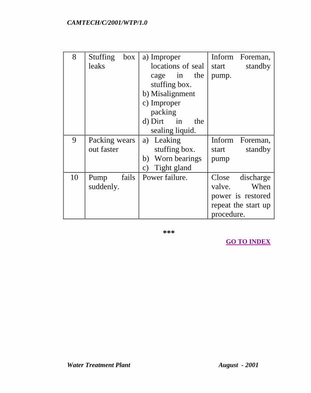
CAMTECH/C/2001/WTP/1.0
Water Treatment Plant August - 2001
8 Stuffing box
leaks
a) Improper
locations of seal
cage in the
stuffing box.
b) Misalignment
c) Improper
packing
d) Dirt in the
sealing liquid.
Inform Foreman,
start standby
pump.
9 Packing wears
out faster
a) Leaking
stuffing box.
b) Worn bearings
c) Tight gland
Inform Foreman,
start standby
pump
10 Pump fails
suddenly.
Power failure. Close discharge
valve. When
power is restored
repeat the start up
procedure.
*** GO TO INDEX

CAMTECH/C/2001/WTP/1.0
Water Treatment Plant August - 2001
CHAPTER - 6
PIPE LINES
Conveyance of water from Source.
a) Gravity conduits should be accurately set out to the
necessary gradient and covered to prevent contamination;
they should be provided at the lowest point with a scour
sluice and with manholes not farther apart than 250 metres
and at all beds and changes of gradient.
b) For pressure mains, galvanised screwed pipes upto 80 mm
diameter may be used; for diameters over 80 mm, cast
iron spigot and socket or reinforced concrete or suitable
asbestos pipes should be used as per relevant BIS
specification.
c) Cast iron pipes – First and second class cast iron pipes in
stock when used should be treated with a suitable solution
in order to reduce corrosion and encrustation.
Pipe laying and Fitting of Valves and Meters
a) The following instructions should be followed :
1) For a gravity line, the pipeline may follow the contour of
the ground so long as frequent and abrupt changes in
gradient are avoided, and it is well below the hydraulic
gradient under conditions of maximum discharge.

CAMTECH/C/2001/WTP/1.0
Water Treatment Plant August - 2001
2) Keep the top of pipe at least 0.5 metres below ground
surface and where severe frost occurs, the cover is at least 1
metre. The bed of the trench shall be finished to an even
gradient/level and filled with soil rammed in 150-mm
layers.
3) Provide air valves at all summits and scour valves at all
sags.
4) Lay spigot and socket pipes with sockets facing the
direction from which the water will flow.
5) Carry pipes across deep depressions or marshy places on
pillars or props.
6) On steep hillsides, anchor the pipe to prevent sliding of
pipes down slope in vertical position, use pipes with
flanged ends and bolts as far as possible.
7) Close the open end of the last pipe at the end of the day’s
work.
8) Test the pipeline with water pressure in sections before the
trench is filled in.
Pipelines should be fitted, where necessary with :
a) Air valves of proper size and pressure rating at summits.
b) Reflex (non-return) valves at the foot of all ascending parts
of the main.

CAMTECH/C/2001/WTP/1.0
Water Treatment Plant August - 2001
c) Scour valves at depressions on the main for clearing
sediment and emptying the pipes.
d) Sluices as necessary in order to divide the main into
convenient section for repairs.
e) A ball cock at the discharge end of a gravitational main
when the discharge into a tank or reservoir is to be
automatically controlled. A ball cock must only be used at
the end of a pumping main if there is a safety or relief valve
on the main.
f) Meters as required.
g) The covers and glands of all valves should be removed,
packing adjusted, spindles and gates examined and the
whole assembly refitted in free and perfect order before
installation.
In tube-wells where centrifugal pumps cannot be installed
sufficiently close to the water table, airlift pumps may be
used. Their efficiency is, however, low and should not
normally be used for capacities in excess of 35000 litres per
hour.
h) Vertical spindle deep well turbine pumps are suitable for
tube wells of large size they are easy to operate and have a
high efficiency. They should be used in tube wells, which
are free from grit and where competent supervisory staffs
are available, as adjustments during repairs require skilled
attention.

CAMTECH/C/2001/WTP/1.0
Water Treatment Plant August - 2001
Submersible pump is suitable for comparatively smaller
installations. It consists of an electric motor and pump both
submerged in water; the vertical spinning shaft is dispensed
with, the water being pumped through a vertical pipe.
i) Pumping units should be so selected that they could be
operated continuously at rated load, as the units are
operated most efficiently at the rated load.
j) Pumping capacity should not exceed the yield of the
source, so as not to damage the strata through which water
filtrates into the source.
*** GO TO INDEX

CAMTECH/C/2001/WTP/1.0
Water Treatment Plant August - 2001
Reference
1. Manual on Water Supply and treatment
(Third Edition – May 1999)
2. Operation and maintenance manual of water treatment
plant, Gwalior.
3. India Railway Works Manual – 2000
4. IS Code –10553 (Part 1) – 1983 – Requirement for
chlorination equipment.
5. IS Code – 9222 (Part 1) 1990 – Recommendations for
handling and dosing devices for chemicals for water
treatment.
6. IS-11401 (Part-2) – General requirements for slow sand
filters.
***
GO TO INDEX
CAMTECH/C/2001/WTP/1.0
Water Treatment Plant August - 2001
OUR OBJECTIVE
If you have any suggestion & any specific comments, please
write to us :
Contact person : Director (Civil)
Postal Address : Centre for Advanced
Maintenance Technology
Maharajpur, Gwalior (M.P.)
Pin code – 474 020
Phone : (0751) - 2470869, 2470803
Fax : (0751) - 2470841
To upgrade Maintenance
Technologies and Methodologies and achieve
improvement in
productivity and performance of all Railway
assets and manpower
which inter-alia would cover Reliability,
Availability, and Utilisation.