Maintaining the Cisco uBR10012 Router · Cisco uBR10012 Universal Broadband Router Software...
48
CHAPTER 5-1 Cisco uBR10012 Universal Broadband Router Hardware Installation Guide 5 Maintaining the Cisco uBR10012 Router The Cisco uBR10012 universal broadband router is configured to your order and ready for installation when it arrives. After you install the system, you may have to perform specific maintenance procedures to ensure the router is operating properly. These procedures can include routine maintenance such as replacing the filter, upgrading system components, or replacing components with field replaceable units (FRUs). This chapter contains the information necessary to perform the following maintenance operations for the Cisco uBR10012 router: • Shutting Down the System, page 5-2 • Removing and Replacing the Front Cover, page 5-2 • Replacing the Air Filter, page 5-4 • Removing and Replacing the Fan Assembly Module, page 5-6 • Removing and Replacing DC Power Entry Modules, page 5-7 • Connecting Alarm Indicators, page 5-7 • Removing and Replacing AC PEM Modules, page 5-9 • Removing and Replacing the PRE Module, page 5-10 • Removing and Installing a PC Media Card, page 5-16 • Removing and Replacing a Timing, Communication, and Control Plus Card, page 5-18 • Removing and Replacing a Network Line Card, page 5-21 • Removing the Half-Height Gigabit Ethernet Line Card and the Slot Splitter, page 5-27 • Replacing the Slot Splitter and Half-Height Gigabit Ethernet Line Card, page 5-32 • Removing and Replacing an SFP Module, page 5-38 • Upgrading to a Half-Height Gigabit Ethernet Line Card, page 5-41 Tip Before beginning any FRU procedure, be sure you are familiar with the safety precautions outlined in Chapter 2, “Preparing for Installation.” System components fall into two categories: hot-swappable components that do not require you to power off the system before replacing them, and those components that do require you to power off the system before you replace them. For example, all line cards are hot-swappable and can be replaced without powering off the system, but you must power off the system before replacing a single power entry module (PEM) or a single performance routing engine (PRE).
Transcript of Maintaining the Cisco uBR10012 Router · Cisco uBR10012 Universal Broadband Router Software...

Cisco uBR10012 Unive
C H A P T E R 5
Maintaining the Cisco uBR10012 RouterThe Cisco uBR10012 universal broadband router is configured to your order and ready for installation when it arrives. After you install the system, you may have to perform specific maintenance procedures to ensure the router is operating properly. These procedures can include routine maintenance such as replacing the filter, upgrading system components, or replacing components with field replaceable units (FRUs).
This chapter contains the information necessary to perform the following maintenance operations for the Cisco uBR10012 router:
• Shutting Down the System, page 5-2
• Removing and Replacing the Front Cover, page 5-2
• Replacing the Air Filter, page 5-4
• Removing and Replacing the Fan Assembly Module, page 5-6
• Removing and Replacing DC Power Entry Modules, page 5-7
• Connecting Alarm Indicators, page 5-7
• Removing and Replacing AC PEM Modules, page 5-9
• Removing and Replacing the PRE Module, page 5-10
• Removing and Installing a PC Media Card, page 5-16
• Removing and Replacing a Timing, Communication, and Control Plus Card, page 5-18
• Removing and Replacing a Network Line Card, page 5-21
• Removing the Half-Height Gigabit Ethernet Line Card and the Slot Splitter, page 5-27
• Replacing the Slot Splitter and Half-Height Gigabit Ethernet Line Card, page 5-32
• Removing and Replacing an SFP Module, page 5-38
• Upgrading to a Half-Height Gigabit Ethernet Line Card, page 5-41
Tip Before beginning any FRU procedure, be sure you are familiar with the safety precautions outlined in Chapter 2, “Preparing for Installation.”
System components fall into two categories: hot-swappable components that do not require you to power off the system before replacing them, and those components that do require you to power off the system before you replace them. For example, all line cards are hot-swappable and can be replaced without powering off the system, but you must power off the system before replacing a single power entry module (PEM) or a single performance routing engine (PRE).
5-1rsal Broadband Router Hardware Installation Guide

Chapter 5 Maintaining the Cisco uBR10012 RouterShutting Down the System
Caution Cisco recommends that you create a duplicate PC media card that contains the current boot software image and the current software configuration. You can use the backup card to quickly recover from a major system failure. You can also use a backup card to load a new PRE module and avoid the time-consuming reconfiguration process. For instructions to create a backup PC media card, refer to the Cisco uBR10012 Router Software Configuration Guide.
Shutting Down the SystemAlthough most components in the Cisco uBR10012 router are hot-swappable, you may have to shut down the system under certain circumstances. Use the following procedure to shut down the system.
Step 1 Notify appropriate personnel that you plan to shut down the system and that the shutdown results in total loss of service. Appropriate personnel includes the regional alarm or network monitoring center, central office personnel, and key customers.
Step 2 Before you shut down the router, use the copy command to save any configuration changes to the NVRAM, and also, if you want, to a PC media card. For instructions on using the copy command, see Cisco uBR10012 Universal Broadband Router Software Configuration Guide.
Step 3 Power down the system by setting the power switch on all PEMs to the Standby (0) position.
Step 4 If you are also using the optional AC-input power shelf, also disconnect the AC power cord for each of the AC-input power modules from the power outlet.
Warning This unit has more than one power supply connection; all connections must be removed completely to completely remove power from the unit. Statement 102
Required Maintenance ToolsThe only tools required to perform the maintenance procedures described in this chapter are:
• A Number 2 Phillips screwdriver
• A flat-blade screwdriver
• An electrostatic discharge (ESD) grounding strap
Removing and Replacing the Front CoverThe Cisco uBR10012 router is equipped with a plastic front cover that ensures proper airflow through the system and protects the cables and connectors from damage. The following procedures describe how to remove and replace the front cover.
5-2Cisco uBR10012 Universal Broadband Router Hardware Installation Guide

Chapter 5 Maintaining the Cisco uBR10012 RouterRemoving and Replacing the Front Cover
Removing the Front CoverUse the following procedure to remove the front cover from the chassis.
Step 1 Remove the cover by lifting it up slightly and then pulling it toward you (see Figure 5-1).
Figure 5-1 Removing the Front Cover
Replacing the Front CoverUse the following procedure to replace the front cover on the chassis.
5642
2
POWERMISWIREFAULT
ALARMS
CISCO10000
FAIL
PE
RF
OR
MA
NC
E R
OU
TIN
G E
NG
INE
CONSO
LE
STATUS
ACO
CRITICAL
MINO
R
MAJO
R
ETHERNETLINK
ACTIVITY
AUX
SLO
T 0
SLO
T 1
ALARMS
CISCO10000
FAIL
PE
RF
OR
MA
NC
E R
OU
TIN
G E
NG
INE
CONSO
LE
STATUS
ACO
CRITICAL
MINO
R
MAJO
R
ETHERNET
LINK
ACTIVITY
AUX
SLO
T 0
SLO
T 1
POWERMISWIREFAULT POWER
MISWIREFAULT
POWERMISWIREFAULT POWER
MISWIREFAULT
IPS
UM
IPS
UM
SA
NC
T
IPS
U S
A T
US
POWERMISWIREFAULT
5-3Cisco uBR10012 Universal Broadband Router Hardware Installation Guide

Chapter 5 Maintaining the Cisco uBR10012 RouterReplacing the Air Filter
Step 1 Slide the cover onto the four corner posts of the chassis and then push down so that the posts are seated in the grooves above the cover holes (see Figure 5-2).
Figure 5-2 Attaching the Cover to the Chassis
Replacing the Air Filter If the air filter is dirty or clogged, the fan assembly module could have a problem providing sufficient cooling airflow throughout the chassis, causing the system to overheat. To prevent a potential overheating problem, you should replace the air filter approximately every 6 to 12 months, depending on how clean and dust-free your operating environment is normally. In certain environments where the air quality is poor, you may have to replace the filter more frequently.
5642
3
POWERMISWIREFAULT
ALARMS
CISCO10000
FAIL
PE
RF
OR
MA
NC
E R
OU
TIN
G E
NG
INE
CONSO
LE
STATUS
ACO
CRITICAL
MINO
R
MAJO
R
ETHERNETLINK
ACTIVITY
AUX
SLO
T 0
SLO
T 1
ALARMS
CISCO10000
FAIL
PE
RF
OR
MA
NC
E R
OU
TIN
G E
NG
INE
CONSO
LE
STATUS
ACO
CRITICAL
MINO
R
MAJO
R
ETHERNET
LINK
ACTIVITY
AUX
SLO
T 0
SLO
T 1
POWERMISWIREFAULT POWER
MISWIREFAULT
POWERMISWIREFAULT POWER
MISWIREFAULT
IPS
UM
IPS
UM
SA
NC
T
IPS
U S
A T
US
POWERMISWIREFAULT
5-4Cisco uBR10012 Universal Broadband Router Hardware Installation Guide

Chapter 5 Maintaining the Cisco uBR10012 RouterReplacing the Air Filter
Note The product order number for a replacement air filter is UBR10-FAN-FILTER=.
Use the following procedure to replace the air filter:
Step 1 Remove the front cover (see “Removing the Front Cover” section on page 5-3).
Step 2 Slide the air filter out of its slot.
Step 3 Discard the old filter.
Figure 5-3 Removing and Inserting the Air Filter
Step 4 Position the new air filter above the tabs on the inside of the front cover and slide it down into the slot. When fully inserted, it should appear as shown in Figure 5-4.
5639
3
5-5Cisco uBR10012 Universal Broadband Router Hardware Installation Guide

Chapter 5 Maintaining the Cisco uBR10012 RouterRemoving and Replacing the Fan Assembly Module
Figure 5-4 Air Filter Inserted into the Front Cover
Step 5 Replace the front cover (see “Replacing the Front Cover”).
Removing and Replacing the Fan Assembly Module
Caution The Cisco uBR10012 chassis should not be run without a working fan assembly module for more than three minutes. To prevent the possibility of the system overheating, be sure that the replacement fan assembly module is out of its box and packaging, so it is ready to install as soon as the defective module is removed.
The fan assembly module does not need to be replaced when it is operating normally. However, if either of the two failure LEDs come on, the fan assembly module should be replaced:
• SINGLE FAN FAILURE—This yellow LED indicates that one of the four fans in the module has failed. The module can still provide enough cooling to safely operate the Cisco uBR10012 chassis, but it might begin operating the fans in its high-speed mode to do so. If this LED lights, the fan assembly module should be replaced as soon as is conveniently possible.
• MULTIPLE FAN FAILURE—This yellow LED indicates that two or more fans in the module have failed, and that the module is no longer able to consistently cool the Cisco uBR10012 chassis. To prevent overheating the chassis and possible damage to the line cards and other modules, the fan assembly module should be replaced immediately.
5639
2
5-6Cisco uBR10012 Universal Broadband Router Hardware Installation Guide

Chapter 5 Maintaining the Cisco uBR10012 RouterRemoving and Replacing DC Power Entry Modules
If the failure LEDs—SINGLE FAN FAILURE and MULTIPLE FAN FAILURE—are illuminated, remove and reinsert the fan assembly module. If the failure LEDs are still illuminated, replace the fan assembly module. The fan assembly module supports hot-swapping and can be replaced without interrupting system operation.
For more information about removing and replacing the fan assembly module, see Cisco uBR10012 Universal Broadband Router Fan Assembly Module.
Removing and Replacing DC Power Entry ModulesThe Cisco uBR10012 router is shipped with two DC power entry modules (PEM) that provide a redundant power supply to the system. One DC PEM can provide sufficient power for a fully configured chassis, so that if one DC PEM fails, the other automatically begins providing power for the entire system. However, the system should not be run for an extended period time with only one DC PEM. If a DC PEM fails, install a replacement DC PEM as soon as possible.
Note You do not need to shut down the Cisco uBR10012 router to replace a redundant DC PEM. And, if you are replacing both DC PEMs, you can replace one, bring it online, and then replace the other one to avoid shutting down the entire system.
The DC PEM is operating correctly when its POWER LED lights (green). Replace a DC PEM if either of the PEM failure LEDs light (yellow):
• MISWIRE—This LED indicates that the wires connecting the PEM to DC power source were wired incorrectly. The DC PEM therefore needs to be removed so that the wiring can be corrected. After the wiring has been corrected, the same DC PEM can be reinserted. See “Connecting Alarm Indicators” section on page 5-7 for more information.
• FAULT—This LED indicates that the DC power source is supplying power but that the DC PEM is not providing power to the system.ced.
Warning Before performing any of the following procedures, ensure that power is removed from the DC circuit. To ensure that all power is OFF, locate the circuit breaker on the panel board that services the DC circuit, switch the circuit breaker to the OFF position, and tape the switch handle of the circuit breaker in the OFF position. Statement 7
For more information on removing and replacing the DC PEM module, see DC Power Entry Module for the Cisco uBR10012 Universal Broadband Router.
For more information on removing and replacing the 3300 W DC PEM, see 3300 W DC Power Entry Module for the Cisco uBR10012 Universal Broadband Router.
Connecting Alarm IndicatorsThe Cisco uBR10012 router provides relay contacts for optional (customer-supplied) audible or visual alarm indicators. Relay contacts are provided for three levels of severity:
• Minor—This is an informational alarm and does not affect the system operation.
• Major—A condition that affects system operation and should be investigated as soon as possible.
• Critical—A condition that affects system operation and requires immediate attention.
5-7Cisco uBR10012 Universal Broadband Router Hardware Installation Guide

Chapter 5 Maintaining the Cisco uBR10012 RouterConnecting Alarm Indicators
If you did not connect the alarm indicators when you originally installed the Cisco uBR10012 chassis, use the following procedure to connect an alarm indicator to the system. For safety and convenience reasons, you need to remove power from the DC PEM on the right side (DC PEM “B”) and remove that DC PEM for easier access to the alarm indicators terminal block.
For more information on removing and replacing the DC PEM module, see DC Power Entry Module for the Cisco uBR10012 Universal Broadband Router.
For more information on removing and replacing the 3300 W DC PEM, see 3300 W DC Power Entry Module for the Cisco uBR10012 Universal Broadband Router.
Attaching the Alarm WiresFor each alarm indicator being connected (minor, major, or critical), use two wires that are long enough to reach between the Cisco uBR10012 chassis and the alarm indicator equipment. Use the gauge of wire required by the audible or visual alarm indicator equipment you are using (14 AWG maximum gauge).
Warning Use copper conductors only. Statement 1025
Caution The alarm contacts on the Cisco uBR10012 router are only relays and do not provide any power from the unit. These relays are rated for 60 VDC, 1 A maximum—ensure that the connected alarm equipment does not exceed these voltage and current ratings.
Step 1 For each pair of wires, strip not more than 0.3 inches (8 mm) of insulation off of the ends of each wire (see Figure 5-5).
Figure 5-5 Stripping Insulation
Step 2 Connect one end of each pair of alarm indicator wires to the alarm terminal block as follows:
a. Connect one lead to the common (COM) terminal.
b. If you are wiring the router in series with other equipment for the alarm indicators, wire the other lead to the normally closed (NC) terminal.
c. If you are wiring the router in parallel with other equipment for the alarm indicators, wire the other lead to the normally open (NO) terminal.
Figure 5-6 shows the wiring configuration for normally open (NO) alarm relays.
Step 3 Connect the other end of this pair of alarm indicator wires to the appropriate connectors on the alarm indicator equipment. Route these cables through the square hole on the bottom right side of the chassis, as you face the front of the chassis.
Step 4 Repeat steps through 3 for the remaining alarm indicators.
Step 5 Secure the cabling to the chassis by feeding a tie wrap through one of the round holes next to the large hole on the side of the chassis. Then use the tie wrap to bind the cables to the chassis.
5868
8
8 mm max
5-8Cisco uBR10012 Universal Broadband Router Hardware Installation Guide
Chapter 5 Maintaining the Cisco uBR10012 RouterRemoving and Replacing AC PEM Modules
Figure 5-6 Alarm Terminal Block Connections
Removing and Replacing AC PEM ModulesThe Cisco uBR10012 router ships with two AC power entry modules (PEMs). In this redundant system, (2 power supplies), one AC PEM provides sufficient power for a fully configured chassis. If one AC PEM fails, the other automatically begins providing power for the entire router, without impacting system operations. However, even though one AC PEM provides sufficient power for a fully configured Cisco uBR10012 chassis, the system should not be run for extended periods of time with only one AC PEM. Always install the replacement AC PEM as soon as possible and order a spare for backup.
Caution For proper airflow, cooling, and safety, do not remove the failed unit until the replacement unit is available for installation.
Caution The Cisco uBR10012 router supports using either the AC PEM or the DC PEM, but it does not support mixing AC and DC PEMs. Both PEMs must be either AC PEMs or DC PEMs.
The AC PEMs use standard 200–240 VAC (50/60 Hz) input power obtained through power receptacles on the front panel of each PEM. The two AC PEMs convert the AC power to provide filtered, redundant, and load shared DC power to the Cisco uBR10012 chassis.
Caution The AC PEMs cannot be used with a 100–120 VAC input power source.
Tip For fully redundant power protection, use either an uninterruptible power supply (UPS) or a separate AC-input power source for each AC PEM.
9874
9
ALARMS60 VDC1A MAX
MINOR
NC NOCOMMAJOR
NC NOCOMCRITICAL
NC NOCOM
MINOR
NC NOCOM
5-9Cisco uBR10012 Universal Broadband Router Hardware Installation Guide

Chapter 5 Maintaining the Cisco uBR10012 RouterRemoving and Replacing the PRE Module
Note You do not need to shut down the Cisco uBR10012 router to replace a redundant AC PEM. If you are replacing both AC PEMs, you can replace one, bring it online, and then replace the other one to avoid shutting down the system.
For information on removing and replacing the AC PEM, see AC Power Entry Module for the Cisco uBR10012 Universal Broadband Router.
For information on removing and replacing the 3300 W AC PEM, see 3300 W AC Power Entry Module for the Cisco uBR10012 Universal Broadband Router.
Removing and Replacing the PRE ModuleIt is not necessary to configure the PRE module if you are installing or replacing a second PRE. The system automatically downloads the necessary configuration information from the primary PRE.
Removing the PRE ModuleUse the following procedure to install a new PRE module, or to replace an existing PRE module.
Step 1 Be sure you are properly grounded.
Step 2 If necessary, remove the blank cover from the PRE module slot and discard.
Step 3 Disconnect any interface cables from the PRE module if necessary.
Step 4 Remove the PC media card from the PRE module (see the “Removing and Installing a PC Media Card” section on page 5-16).
Step 5 Unscrew the top and bottom captive screws on the PRE module (see Figure 5-7).
5-10Cisco uBR10012 Universal Broadband Router Hardware Installation Guide

Chapter 5 Maintaining the Cisco uBR10012 RouterRemoving and Replacing the PRE Module
Figure 5-7 Loosening the Captive Screws
Step 6 Simultaneously pivot both ejector levers away from each other to disengage the PRE module from the backplane (see Figure 5-8).
5642
4
ALARMS
CISCO10000
FAIL
PE
RF
OR
MA
NC
E R
OU
TIN
G E
NG
INE
CONSO
LE
STATUS
ACO
CRITICAL
MINO
R
MAJO
R
ETHERNETLINK
ACTIVITY
AUX
SLO
T 0
SLO
T 1
ALARMS
CISCO10000
FAIL
PE
RF
OR
MA
NC
E R
OU
TIN
G E
NG
INE
CONSO
LE
STATUS
ACO
CRITICAL
MINO
R
MAJO
R
ETHERNET
LINK
ACTIVITY
AUX
SLO
T 0
SLO
T 1
Captive screw
Captive screw
POWERMISWIREFAULT
POWERMISWIREFAULT
5-11Cisco uBR10012 Universal Broadband Router Hardware Installation Guide

Chapter 5 Maintaining the Cisco uBR10012 RouterRemoving and Replacing the PRE Module
Figure 5-8 Opening the Ejector Levers
Step 7 Slide the PRE module out of the slot and place it on an antistatic surface, or in an antistatic bag (see Figure 5-9).
ALARMS
CISCO10000
FAIL
PE
RF
OR
MA
NC
E R
OU
TIN
G E
NG
INE
CONSO
LE
STATUS
ACO
CRITICAL
MINO
R
MAJO
R
ETHERNETLINK
ACTIVITY
AUX
SLO
T 0
SLO
T 1
ALARMS
CISCO10000
FAIL
PE
RF
OR
MA
NC
E R
OU
TIN
G E
NG
INE
CONSO
LE
STATUS
ACO
CRITICAL
MINO
R
MAJO
R
ETHERNET
LINK
ACTIVITY
AUX
SLO
T 0
SLO
T 1
POWERMISWIREFAULT
POWERMISWIREFAULT
5642
5
FAIL
STATUS
FAIL
STATUS
C10000PRE
CONSO
LE
ETHERNETLINK
ACTIVITY
AUX
SLO
T 1
CONSO
LE
AUX
CISCO10000
CISCO10000
SLO
T 0
5-12Cisco uBR10012 Universal Broadband Router Hardware Installation Guide

Chapter 5 Maintaining the Cisco uBR10012 RouterRemoving and Replacing the PRE Module
Figure 5-9 Removing the PRE Module from the Chassis
Step 8 If you are installing a new or replacement PRE module, proceed to the next step. Otherwise, install a blank cover over the slot and screw down its captive screws to conclude this procedure.
Note For proper cooling and airflow, a blank PRE module cover should always be installed when a second PRE module is not installed.
The product order number for the blank PRE module cover is ESR-PRE-COVER=.
Warning Blank faceplates and cover panels serve three important functions: they prevent exposure to hazardous voltages and currents inside the chassis; they contain electromagnetic interference (EMI) that might disrupt other equipment; and they direct the flow of cooling air through the chassis. Do not operate the system unless all cards, faceplates, front covers, and rear covers are in place. Statement 1029
5629
2
ALARMS
CISCO10000
FAIL
PE
RF
OR
MA
NC
E R
OU
TIN
G E
NG
INE
CONSO
LE
STATUS
ACO
CRITICAL
MINO
R
MAJO
R
ETHERNELINK
ACTIVITY
AUX
SLO
T 0
SLO
T 1
PE
RF
OR
MA
NC
E R
OU
TIN
G E
NG
INE
ALARMS
CISCO10000
FAIL
PE
RF
OR
MA
NC
E R
OU
TIN
G E
NG
INE
CONSO
LE
STATUS
ACO
CRITICAL
MINO
R
MAJO
R
ETHERNETLINK
ACTIVITY
AUX
SLO
T 0
SLO
T 1
POWERMISWIREFAULT
POWERMISWIREFAULT
5-13Cisco uBR10012 Universal Broadband Router Hardware Installation Guide

Chapter 5 Maintaining the Cisco uBR10012 RouterRemoving and Replacing the PRE Module
Replacing the PRE ModuleWhen replacing a PRE1 module with a PRE2 module, you must also install EMI gaskets and RF absorber material, for more information, go to the following URL:
http://www.cisco.com/en/US/docs/cable/cmts/ubr10012/installation/field_replaceable_units/pre2gkit.html
Step 1 Grasp the faceplate of the new PRE module with one hand and place your other hand under the card carrier (to support the weight of the module) and position the card in front of the card cage slot.
Step 2 Carefully align the upper and lower edges of the PRE module with the upper and lower guides in the chassis, and slide the module into the slot until you can feel it begin to seat in the backplane connectors (see Figure 5-10).
Figure 5-10 Inserting the PRE Module in the Chassis
Step 3 Simultaneously pivot both ejector levers toward each other (until they are parallel to the faceplate) to firmly seat the PRE module in the backplane (see Figure 5-11).
Step 4 Secure the PRE module in the chassis by tightening the top and bottom captive screws (see Figure 5-7).
Caution Always tighten the captive screws on each newly installed PRE module. These screws prevent accidental removal and provide proper grounding for electromagnetic interference (EMI) shielding.
5642
7
ALARMS
CISCO10000
FAIL
PE
RF
OR
MA
NC
E R
OU
TIN
G E
NG
INE
CONSO
LE
STATUS
ACO
CRITICAL
MINO
R
MAJO
R
ETHERNELINK
ACTIVITY
AUX
SLO
T 0
SLO
T 1
PE
RF
OR
MA
NC
E R
OU
TIN
G E
NG
INE
ALARMS
CISCO10000
FAIL
PE
RF
OR
MA
NC
E R
OU
TIN
G E
NG
INE
CONSO
LE
STATUS
ACO
CRITICAL
MINO
R
MAJO
R
ETHERNETLINK
ACTIVITY
AUX
SLO
T 0
SLO
T 1
POWERMISWIREFAULT
POWERMISWIREFAULT
5-14Cisco uBR10012 Universal Broadband Router Hardware Installation Guide

Chapter 5 Maintaining the Cisco uBR10012 RouterRemoving and Replacing the PRE Module
Figure 5-11 Closing the Ejector Levers
Step 5 When fully inserted, the PRE module cycles through its power-on self-test. The FAIL LED stays on briefly (about 5 to 6 seconds) and then shuts off. If the FAIL LED remains on or is flashing, go to the “Troubleshooting Installation Problems” section on page 4-3.
Step 6 Reconnect any interface cables to the PRE module if necessary. Route the cables through the square hole in the front left side on the chassis.
Step 7 Install the PC media card in the PRE module, if necessary (see the Removing and Installing a PC Media Card).
ALARMS
CISCO10000
FAIL
PE
RF
OR
MA
NC
E R
OU
TIN
G E
NG
INE
CONSO
LE
STATUS
ACO
CRITICAL
MINO
R
MAJO
R
ETHERNETLINK
ACTIVITY
AUX
SLO
T 0
SLO
T 1
ALARMS
CISCO10000
FAIL
PE
RF
OR
MA
NC
E R
OU
TIN
G E
NG
INE
CONSO
LE
STATUS
ACO
CRITICAL
MINO
R
MAJO
R
ETHERNET
LINK
ACTIVITY
AUX
SLO
T 0
SLO
T 1
POWERMISWIREFAULT
POWERMISWIREFAULT
5642
6
FAIL
STATUS
FAIL
STATUS
C10000PRE
CONSO
LE
ETHERNETLINK
ACTIVITY
AUX
SLO
T 1
CONSO
LE
AUX
CISCO10000
CISCO10000
SLO
T 0
5-15Cisco uBR10012 Universal Broadband Router Hardware Installation Guide

Chapter 5 Maintaining the Cisco uBR10012 RouterRemoving and Installing a PC Media Card
Removing and Installing a PC Media CardUse the following procedure to remove and install a PC media card.
Note The Cisco uBR10012 router uses PC media cards that are a minimum of 64 MB in size. For information about formatting media cards and disks, see the “Formatting PC Media Cards” section on page 3-71.
Step 1 Loosen the captive screw on the PC media card cover on the PRE (see Figure 5-12).
Figure 5-12 PC Media Card Cover Captive Screws
Step 2 Lift the cover, push the proper eject button, and pull the Flash card out of its slot (see Figure 5-13).
5642
8
POWERMISWIREFAULT
POWERMISWIREFAULT
ALARMS
CISCO10000
FAIL
PE
RF
OR
MA
NC
E R
OU
TIN
G E
NG
INE
CONSO
LE
STATUS
ACO
CRITICAL
MINO
R
MAJO
R
ETHERNETLINK
ACTIVITY
AUX
SLO
T 0
SLO
T 1
ALARMS
CISCO10000
FAIL
PE
RF
OR
MA
NC
E R
OU
TIN
G E
NG
INE
CONSO
LE
STATUS
ACO
CRITICAL
MINO
R
MAJO
R
ETHERNET
LINK
ACTIVITY
AUX
SLO
T 0
SLO
T 1
Captivescrew
1
0
5-16Cisco uBR10012 Universal Broadband Router Hardware Installation Guide

Chapter 5 Maintaining the Cisco uBR10012 RouterRemoving and Installing a PC Media Card
Figure 5-13 Removing the PC Media Card
Step 3 Insert the new PC media card into one of the card slots on the PRE (see Figure 5-14).
Figure 5-14 Inserting the PC Media Card
Step 4 Close the cover and tighten the captive screw to maintain proper EMI emissions levels (see Figure 5-12).
3269
0
CONSO
LE
ETHERNETLINK
ACTIVITY
AUX
SLO
T 0
SLO
T 1
CISCO10000
3269
1
CONSO
LE
ETHERNETLINK
ACTIVITY
AUX
SLO
T 0
SLO
T 1
CISCO10000
5-17Cisco uBR10012 Universal Broadband Router Hardware Installation Guide

Chapter 5 Maintaining the Cisco uBR10012 RouterRemoving and Replacing a Timing, Communication, and Control Plus Card
Removing and Replacing a Timing, Communication, and Control Plus Card
Use the following procedure to install a new Timing, Communication, and Control Plus (TCC+) card or to replace an existing TCC+ card. If two TCC+ cards are installed for redundant operation, one of the cards can be removed and replaced without interrupting system operations.
Note The product order number for the TCC+ card is UBR10-TCC+=
Step 1 Attach an antistatic wrist strap to your wrist and to a bare metal, unpainted surface on the chassis or frame.
Step 2 Face the back of the Cisco uBR10012 chassis. If necessary, clear aside enough interface and power cables to allow sufficient space to work.
Step 3 If installing a new TCC+ card, remove the blank slot cover and discard, and then proceed to step 8. Otherwise, disconnect the clock cables from the TCC+ card being replaced.
Step 4 Loosen the top and bottom captive screws on the TCC+ card (see Figure 5-15).
Figure 5-15 TCC+ Card Captive Screws
Step 5 Verify that the maintenance LED is lighted on the TCC+ card you are removing. This LED indicates that the card can be removed from the chassis without interrupting systems operations.
Step 6 Using the handle, pull the TCC+ card out of the slot and place it on an antistatic surface, or in an antistatic bag (see Figure 5-16).
CISCO10000
FAIL
CISCO10000
FAIL
CISCO10000
FAIL
CISC100
FAIL
US0
US1
US2
US3
US4
US5
US6
US7
US8
US9
uB
R10-M
C5x2
0S
-D
POWER
STATUSM
AINT
US0
US1
US2
US3
US4
US5
US6
US7
US8
US9
uB
R10-M
C5x2
0S
-D
POWER
STATUSM
AINT
US0
US1
US2
US3
US4
US5
US6
US7
US8
US9
uB
R10-M
C5x2
0S
-D
POWER
STATUSM
AINT
US0
US1
US2
US3
US4
US5
US6
US7
US8
US9
uB
R10-M
C5x2
0S
-D
POWER
STATUSM
AINT
US0
US1
US2
US3
US4
US5
US6
US7
US8
US9
uB
R10-M
C5x2
0S
-D
POWER
STATUSM
AINT
US0
US1
US2
US3
US4
US5
US6
US7
US8
US9
uB
R10-M
C5x2
0S
-D
POWER
STATUSM
AINT
US0
US1
US2
US3
US4
US5
US6
US7
US8
US9
uB
R10-M
C5x2
0S
-D
POWER
STATUSM
AINT
US0
US1
US2
US3
US4
US5
US6
US7
US8
US9
uB
R10-M
C5x2
0S
-D
POWER
STATUSM
AINT
5645
6
Captive screws
5-18Cisco uBR10012 Universal Broadband Router Hardware Installation Guide

Chapter 5 Maintaining the Cisco uBR10012 RouterRemoving and Replacing a Timing, Communication, and Control Plus Card
Figure 5-16 Removing the TCC+ card
Step 7 If you are installing a replacement card, proceed to the next step. Otherwise, install a blank cover over the slot and screw down its captive screws to conclude this procedure.
Note For proper cooling and airflow, a cover must always be installed in a blank TCC+ card slot. The product order number for the blank TCC+ card cover is UBR10-TCC+-COVER=.
Warning Blank faceplates (filler panels) serve three important functions: they prevent exposure to hazardous voltages and currents inside the chassis; they contain electromagnetic interference (EMI) that might disrupt other equipment; and they direct the flow of cooling air through the chassis. Do not operate the system unless all cards and faceplates are in place. Statement 1029
Step 8 Pick up the replacement TCC+ card and position it in front of the card cage slot.
Step 9 Carefully align the upper and lower edges of the line card with the upper and lower guides in the chassis, and slide the line card into the slot so that it firmly seats in the backplane connectors (see Figure 5-17).
CISCO10000
FAIL
CISCO10000
FAIL
CISCO10000
FAIL
CISC100
FAIL
US0
US1
US2
US3
US4
US5
US6
US7
US8
US9
uB
R10-M
C5x2
0S
-D
POWER
STATUSM
AINT
US0
US1
US2
US3
US4
US5
US6
US7
US8
US9
uB
R10-M
C5x2
0S
-D
POWER
STATUSM
AINT
US0
US1
US2
US3
US4
US5
US6
US7
US8
US9
uB
R10-M
C5x2
0S
-D
POWER
STATUSM
AINT
US0
US1
US2
US3
US4
US5
US6
US7
US8
US9
uB
R10-M
C5x2
0S
-D
POWER
STATUSM
AINT
US0
US1
US2
US3
US4
US5
US6
US7
US8
US9
uB
R10-M
C5x2
0S
-D
POWER
STATUSM
AINT
US0
US1
US2
US3
US4
US5
US6
US7
US8
US9
uB
R10-M
C5x2
0S
-D
POWER
STATUSM
AINT
US0
US1
US2
US3
US4
US5
US6
US7
US8
US9
uB
R10-M
C5x2
0S
-D
POWER
STATUSM
AINT
US0
US1
US2
US3
US4
US5
US6
US7
US8
US9
uB
R10-M
C5x2
0S
-D
POWER
STATUSM
AINT
5645
7
5-19Cisco uBR10012 Universal Broadband Router Hardware Installation Guide

Chapter 5 Maintaining the Cisco uBR10012 RouterRemoving and Replacing a Timing, Communication, and Control Plus Card
Figure 5-17 Inserting the TCC+ Card
Step 10 Secure the line card in the chassis by tightening the top and bottom captive screws (see Figure 5-15).
Caution Always tighten the captive screws on each TCC+ card. These screws prevent accidental removal and provide proper grounding for electromagnetic interference (EMI) shielding.
Step 11 When fully inserted, the TCC+ card cycles through its power-on self-test. The Power LED lights (green) and the Status LED then briefly lights (yellow). If this is the primary (or only) TCC+ card, the Status LED then lights a solid green. On the backup TCC+ card, the Status LED should start flashing green after a few moments. If these LEDs do not operate as described, go to the “Troubleshooting Installation Problems” section on page 4-3.
Step 12 Connect the clock cables to the TCC+ card.
Caution The TCC+ card can connect only to a national clock source such as a GPS receiver or Building Integrated Timing Supply (BITS) clock. The Cisco uBR10012 router does not support directly connecting the RJ-45 connectors on the TCC+ cards to an outside plant line or telco-provided T1/E1 clock source. You can use an outside or telco-provided T1/E1 clock source only by connecting the source to the TCC+ cards using a CSU/DSU or other equipment that is approved to FCC part 68 and ANSI/UL1950 for the connection to the Public Switched Telephone Network (PSTN).
Note It is not necessary to configure the TCC+ card if you are installing a replacement card in the same slot. The system automatically downloads the necessary configuration information from the PRE module.
Step 13 Configure the TCC+ card if necessary (see the “Formatting PC Media Cards” section on page 3-71.
CISCO10000
FAIL
CISCO10000
FAIL
CISCO10000
FAIL
CISC100
FAIL
US0
US1
US2
US3
US4
US5
US6
US7
US8
US9
uB
R10-M
C5x2
0S
-D
POWER
STATUSM
AINT
US0
US1
US2
US3
US4
US5
US6
US7
US8
US9
uB
R10-M
C5x2
0S
-D
POWER
STATUSM
AINT
US0
US1
US2
US3
US4
US5
US6
US7
US8
US9
uB
R10-M
C5x2
0S
-D
POWER
STATUSM
AINT
US0
US1
US2
US3
US4
US5
US6
US7
US8
US9
uB
R10-M
C5x2
0S
-D
POWER
STATUSM
AINT
US0
US1
US2
US3
US4
US5
US6
US7
US8
US9
uB
R10-M
C5x2
0S
-D
POWER
STATUSM
AINT
US0
US1
US2
US3
US4
US5
US6
US7
US8
US9
uB
R10-M
C5x2
0S
-D
POWER
STATUSM
AINT
US0
US1
US2
US3
US4
US5
US6
US7
US8
US9
uB
R10-M
C5x2
0S
-D
POWER
STATUSM
AINT
US0
US1
US2
US3
US4
US5
US6
US7
US8
US9
uB
R10-M
C5x2
0S
-D
POWER
STATUSM
AINT
5645
8
5-20Cisco uBR10012 Universal Broadband Router Hardware Installation Guide

Chapter 5 Maintaining the Cisco uBR10012 RouterRemoving and Replacing a Network Line Card
Removing and Replacing a Network Line CardUse the following procedure to install a new network line card, or to remove or replace an existing network line card in the Cisco uBR10012 chassis. The following cards are supported:
• Cisco OC-12/STS12c/STM4 POS (UBR10-OC12/P-SMI=)
• Cisco uBR10-SRP-OC12SML-DPT WAN (UBR10-SRP-OC12SML=)
• Cisco Single Port Gigabit Ethernet line card (UBR10-1GE=)
• Cisco uBR10012 OC-48 DPT/POS interface module
Tip To prevent alarms from activating, you can administratively shut down a line card before hot-swapping it. Otherwise, inform the network administrator that this portion of the network will be temporarily interrupted.
Removing the Network Line Card
Warning Class 1 laser product. Statement 1008
Warning Invisible laser radiation present. Statement 1016
Warning Because invisible radiation may be emitted from the aperture of the port when no fiber cable is connected, avoid exposure to radiation and do not stare into open apertures. Statement 1056
Warning Statement for Sweden
Warning Osynlig laserstrålning när denna del är öppen och förregleringen är urkopplad. Rikta inte blicken in mot strålen. Statement 1036
Warning Statement for Finland
Warning Alleviates ja suojalukitus ohitettaessa olet alttiina näkymättömälle lasersäteilylle. Äjä katso säteeseen. Statement 1035
Step 1 Attach an antistatic wrist strap to your wrist and to a bare metal surface on the chassis or frame.
Step 2 Face the back of the Cisco uBR10012 chassis. Clear aside enough interface and power cables to allow sufficient space to work.
5-21Cisco uBR10012 Universal Broadband Router Hardware Installation Guide

Chapter 5 Maintaining the Cisco uBR10012 RouterRemoving and Replacing a Network Line Card
Figure 5-18 Loosening the Captive Screws
Step 3 If installing a new line card in a blank slot, remove the blank slot cover and discard. Otherwise, disconnect the cables from the network line card.
Step 4 Unscrew the top and bottom captive screws on the card (see Figure 5-18).
Step 5 Simultaneously pivot both ejector levers away from each other to disengage the line card from the backplane (see Figure 5-19).
1034
91
CISCO10000
CA
RR
IER
ALA
RM
LOO
P
FAIL
CH
OC
-12-DS
O S
M-IR
CISCO10000
CA
RR
IER
ALA
RM
LOO
P
FAIL
CH
OC
-12-DS
O S
M-IR
CISCO10000
CA
RR
IER
ALA
RM
LOO
P
FAIL
CH
OC
-12-DS
O S
M-IR
CISC100
CA
RR
IER
ALA
RM
LFA
IL
Captive screws
US0
US1
US2
US3
US4
US5
US6
US7
US8
US9
US10
US11
US12
US13
US14
US15
US16
US17
US18
US19
DS0
DS1
DS2
DS3
DS4
RF
RF
RF
RF
RF
uB
R10-M
C5x2
0S
-D
POWER
STATUSM
AINT
US0
US1
US2
US3
US4
US5
US6
US7
US8
US9
US10
US11
US12
US13
US14
US15
US16
US17
US18
US19
DS0
DS1
DS2
DS3
DS4
RF
RF
RF
RF
RF
uB
R10-M
C5x2
0S
-D
POWER
STATUSM
AINT
US0
US1
US2
US3
US4
US5
US6
US7
US8
US9
US10
US11
US12
US13
US14
US15
US16
US17
US18
US19
DS0
DS1
DS2
DS3
DS4
RF
RF
RF
RF
RF
uB
R10-M
C5x2
0S
-D
POWER
STATUSM
AINT
US0
US1
US2
US3
US4
US5
US6
US7
US8
US9
US10
US11
US12
US13
US14
US15
US16
US17
US18
US19
DS0
DS1
DS2
DS3
DS4
RF
RF
RF
RF
RF
uB
R10-M
C5x2
0S
-D
POWER
STATUSM
AINT
US0
US1
US2
US3
US4
US5
US6
US7
US8
US9
US10
US11
US12
US13
US14
US15
US16
US17
US18
US19
DS0
DS1
DS2
DS3
DS4
RF
RF
RF
RF
RF
uB
R10-M
C5x2
0S
-D
POWER
STATUSM
AINT
US0
US1
US2
US3
US4
US5
US6
US7
US8
US9
US10
US11
US12
US13
US14
US15
US16
US17
US18
US19
DS0
DS1
DS2
DS3
DS4
RF
RF
RF
RF
RF
uB
R10-M
C5x2
0S
-D
POWER
STATUSM
AINT
US0
US1
US2
US3
US4
US5
US6
US7
US8
US9
US10
US11
US12
US13
US14
US15
US16
US17
US18
US19
DS0
DS1
DS2
DS3
DS4
RF
RF
RF
RF
RF
uB
R10-M
C5x2
0S
-D
POWER
STATUSM
AINT
US0
US1
US2
US3
US4
US5
US6
US7
US8
US9
US10
US11
US12
US13
US14
US15
US16
US17
US18
US19
DS0
DS1
DS2
DS3
DS4
RF
RF
RF
RF
RF
uB
R10-M
C5x2
0S
-D
POWER
STATUSM
AINT
Captivescrews
5-22Cisco uBR10012 Universal Broadband Router Hardware Installation Guide

Chapter 5 Maintaining the Cisco uBR10012 RouterRemoving and Replacing a Network Line Card
Figure 5-19 Opening the Ejector Levers
Step 6 Slide the card out of the slot and place it on an antistatic surface, or in an antistatic bag (see Figure 5-20).
1034
92
CISCO10000
CA
RR
IER
ALA
RM
LOO
P
FAIL
CH
OC
-12-DS
O S
M-IR
CISCO10000
CA
RR
IER
ALA
RM
LOO
P
FAIL
CH
OC
-12-DS
O S
M-IR
CISCO10000
CA
RR
IER
ALA
RM
LOO
P
FAIL
CH
OC
-12-DS
O S
M-IR
CISC100
CA
RR
IER
ALA
RM
LFA
IL
CISCO10000
FAIL
CISCO10000
FAIL
CISCO10000
FAIL
CISCO10000
FAIL
US0
US1
US2
US3
US4
US5
US6
US7
US8
US9
US10
US11
US12
US13
US14
US15
US16
US17
US18
US19
DS0
DS1
DS2
DS3
DS4
RF
RF
RF
RF
RF
uB
R10-M
C5x2
0S
-D
POWER
STATUSM
AINT
US0
US1
US2
US3
US4
US5
US6
US7
US8
US9
US10
US11
US12
US13
US14
US15
US16
US17
US18
US19
DS0
DS1
DS2
DS3
DS4
RF
RF
RF
RF
RF
uB
R10-M
C5x2
0S
-D
POWER
STATUSM
AINT
US0
US1
US2
US3
US4
US5
US6
US7
US8
US9
US10
US11
US12
US13
US14
US15
US16
US17
US18
US19
DS0
DS1
DS2
DS3
DS4
RF
RF
RF
RF
RF
uB
R10-M
C5x2
0S
-D
POWER
STATUSM
AINT
US0
US1
US2
US3
US4
US5
US6
US7
US8
US9
US10
US11
US12
US13
US14
US15
US16
US17
US18
US19
DS0
DS1
DS2
DS3
DS4
RF
RF
RF
RF
RF
uB
R10-M
C5x2
0S
-D
POWER
STATUSM
AINT
US0
US1
US2
US3
US4
US5
US6
US7
US8
US9
US10
US11
US12
US13
US14
US15
US16
US17
US18
US19
DS0
DS1
DS2
DS3
DS4
RF
RF
RF
RF
RF
uB
R10-M
C5x2
0S
-D
POWER
STATUSM
AINT
US0
US1
US2
US3
US4
US5
US6
US7
US8
US9
US10
US11
US12
US13
US14
US15
US16
US17
US18
US19
DS0
DS1
DS2
DS3
DS4
RF
RF
RF
RF
RF
uB
R10-M
C5x2
0S
-D
POWER
STATUSM
AINT
US0
US1
US2
US3
US4
US5
US6
US7
US8
US9
US10
US11
US12
US13
US14
US15
US16
US17
US18
US19
DS0
DS1
DS2
DS3
DS4
RF
RF
RF
RF
RF
uB
R10-M
C5x2
0S
-D
POWER
STATUSM
AINT
US0
US1
US2
US3
US4
US5
US6
US7
US8
US9
US10
US11
US12
US13
US14
US15
US16
US17
US18
US19
DS0
DS1
DS2
DS3
DS4
RF
RF
RF
RF
RF
uB
R10-M
C5x2
0S
-D
POWER
STATUSM
AINT
5-23Cisco uBR10012 Universal Broadband Router Hardware Installation Guide

Chapter 5 Maintaining the Cisco uBR10012 RouterRemoving and Replacing a Network Line Card
Figure 5-20 Removing the Network Line Card
Step 7 If you are installing a new or replacement card, proceed to the next step. Otherwise, install a blank cover over the slot and screw down its captive screws to conclude this procedure.
Warning Blank faceplates (filler panels) serve three important functions: they prevent exposure to hazardous voltages and currents inside the chassis; they contain electromagnetic interference (EMI) that might disrupt other equipment; and they direct the flow of cooling air through the chassis. Do not operate the system unless all cards and faceplates are in place. Statement 1029
1034
93
CISCO10000
CA
RR
IER
ALA
RM
LOO
P
FAIL
CH
OC
-12-DS
O S
M-IR
CISCO10000
CA
RR
IER
ALA
RM
LOO
P
FAIL
CH
OC
-12-DS
O S
M-IR
CISC100
ALA
RM
LFA
IL
US0
US1
US2
US3
US4
US5
US6
US7
US8
US9
US10
US11
US12
US13
US14
US15
US16
US17
US18
US19
DS0
DS1
DS2
DS3
DS4
RF
RF
RF
RF
RF
uB
R10-M
C5x2
0S
-D
POWER
STATUSM
AINT
US0
US1
US2
US3
US4
US5
US6
US7
US8
US9
US10
US11
US12
US13
US14
US15
US16
US17
US18
US19
DS0
DS1
DS2
DS3
DS4
RF
RF
RF
RF
RF
uB
R10-M
C5x2
0S
-D
POWER
STATUSM
AINT
US0
US1
US2
US3
US4
US5
US6
US7
US8
US9
US10
US11
US12
US13
US14
US15
US16
US17
US18
US19
DS0
DS1
DS2
DS3
DS4
RF
RF
RF
RF
RF
uB
R10-M
C5x2
0S
-D
POWER
STATUSM
AINT
US0
US1
US2
US3
US4
US5
US6
US7
US8
US9
US10
US11
US12
US13
US14
US15
US16
US17
US18
US19
DS0
DS1
DS2
DS3
DS4
RF
RF
RF
RF
RF
uB
R10-M
C5x2
0S
-D
POWER
STATUSM
AINT
US0
US1
US2
US3
US4
US5
US6
US7
US8
US9
US10
US11
US12
US13
US14
US15
US16
US17
US18
US19
DS0
DS1
DS2
DS3
DS4
RF
RF
RF
RF
RF
uB
R10-M
C5x2
0S
-D
POWER
STATUSM
AINT
US0
US1
US2
US3
US4
US5
US6
US7
US8
US9
US10
US11
US12
US13
US14
US15
US16
US17
US18
US19
DS0
DS1
DS2
DS3
DS4
RF
RF
RF
RF
RF
uB
R10-M
C5x2
0S
-D
POWER
STATUSM
AINT
US0
US1
US2
US3
US4
US5
US6
US7
US8
US9
US10
US11
US12
US13
US14
US15
US16
US17
US18
US19
DS0
DS1
DS2
DS3
DS4
RF
RF
RF
RF
RF
uB
R10-M
C5x2
0S
-D
POWER
STATUSM
AINT
US0
US1
US2
US3
US4
US5
US6
US7
US8
US9
US10
US11
US12
US13
US14
US15
US16
US17
US18
US19
DS0
DS1
DS2
DS3
DS4
RF
RF
RF
RF
RF
uB
R10-M
C5x2
0S
-D
POWER
STATUSM
AINT
CONSO
LE
ETHERNETLINK
ACTIVITY
AUX
SLO
T 0
SLO
T 1
CA
RR
IER
ALA
RM
LOO
P
0
5
4
3
2
1
CA
RR
IER
ALA
RM
LOO
P
0
5
4
3
2
1
CISCO10000
CA
RR
IER
ALA
RM
LOO
P
FAIL
CH
OC
-12-DS
O S
M-IR
5-24Cisco uBR10012 Universal Broadband Router Hardware Installation Guide

Chapter 5 Maintaining the Cisco uBR10012 RouterRemoving and Replacing a Network Line Card
Installing the Network Line Card
Note For proper cooling and airflow, a blank card cover must always be installed in a blank line card slot. The product order number for the blank card cover is ESR-LC-Cover=.
Step 1 Grasp the faceplate of the new card with one hand and place your other hand under the card carrier (to support the weight of the card) and position the card in front of the card cage slot.
Step 2 Carefully align the upper and lower edges of the line card with the upper and lower guides in the chassis, and slide the line card into the slot until you can feel it begin to seat in the backplane connectors (see Figure 5-21).
Figure 5-21 Inserting the Network Line Card
1034
94
CISCO10000
CA
RR
IER
ALA
RM
LOO
P
FAIL
CH
OC
-12-DS
O S
M-IR
CISCO10000
CA
RR
IER
ALA
RM
LOO
P
FAIL
CH
OC
-12-DS
O S
M-IR
CISC100
ALA
RM
LFA
IL
US0
US1
US2
US3
US4
US5
US6
US7
US8
US9
US10
US11
US12
US13
US14
US15
US16
US17
US18
US19
DS0
DS1
DS2
DS3
DS4
RF
RF
RF
RF
RF
uB
R10-M
C5x2
0S
-D
POWER
STATUSM
AINT
US0
US1
US2
US3
US4
US5
US6
US7
US8
US9
US10
US11
US12
US13
US14
US15
US16
US17
US18
US19
DS0
DS1
DS2
DS3
DS4
RF
RF
RF
RF
RF
uB
R10-M
C5x2
0S
-D
POWER
STATUSM
AINT
US0
US1
US2
US3
US4
US5
US6
US7
US8
US9
US10
US11
US12
US13
US14
US15
US16
US17
US18
US19
DS0
DS1
DS2
DS3
DS4
RF
RF
RF
RF
RF
uB
R10-M
C5x2
0S
-D
POWER
STATUSM
AINT
US0
US1
US2
US3
US4
US5
US6
US7
US8
US9
US10
US11
US12
US13
US14
US15
US16
US17
US18
US19
DS0
DS1
DS2
DS3
DS4
RF
RF
RF
RF
RF
uB
R10-M
C5x2
0S
-D
POWER
STATUSM
AINT
US0
US1
US2
US3
US4
US5
US6
US7
US8
US9
US10
US11
US12
US13
US14
US15
US16
US17
US18
US19
DS0
DS1
DS2
DS3
DS4
RF
RF
RF
RF
RF
uB
R10-M
C5x2
0S
-D
POWER
STATUSM
AINT
US0
US1
US2
US3
US4
US5
US6
US7
US8
US9
US10
US11
US12
US13
US14
US15
US16
US17
US18
US19
DS0
DS1
DS2
DS3
DS4
RF
RF
RF
RF
RF
uB
R10-M
C5x2
0S
-D
POWER
STATUSM
AINT
US0
US1
US2
US3
US4
US5
US6
US7
US8
US9
US10
US11
US12
US13
US14
US15
US16
US17
US18
US19
DS0
DS1
DS2
DS3
DS4
RF
RF
RF
RF
RF
uB
R10-M
C5x2
0S
-D
POWER
STATUSM
AINT
US0
US1
US2
US3
US4
US5
US6
US7
US8
US9
US10
US11
US12
US13
US14
US15
US16
US17
US18
US19
DS0
DS1
DS2
DS3
DS4
RF
RF
RF
RF
RF
uB
R10-M
C5x2
0S
-D
POWER
STATUSM
AINT
CONSO
LE
ETHERNETLINK
ACTIVITY
AUX
SLO
T 0
SLO
T 1
CA
RR
IER
ALA
RM
LOO
P
0
5
4
3
2
1
CA
RR
IER
ALA
RM
LOO
P
0
5
4
3
2
1
CISCO10000
CA
RR
IER
ALA
RM
LOO
P
FAIL
CH
OC
-12-DS
O S
M-IR
5-25Cisco uBR10012 Universal Broadband Router Hardware Installation Guide

Chapter 5 Maintaining the Cisco uBR10012 RouterRemoving and Replacing a Network Line Card
Step 3 Simultaneously pivot both ejector levers toward each other (until they are parallel to the faceplate) to firmly seat the card in the backplane (see Figure 5-22).
Figure 5-22 Closing the Ejector Levers
Step 4 Secure the network line card in the chassis by tightening the top and bottom captive screws (see Figure 5-18).
Caution To ensure that there is adequate space for additional line cards, always tighten the captive screws on each newly installed line card before you insert any additional line cards. These screws prevent accidental removal and provide proper grounding for electromagnetic interference (EMI) shielding.
US0
US1
US2
US3
US4
US5
US6
US7
US8
US9
US10
US11
US12
US13
US14
US15
US16
US17
US18
US19
DS0
DS1
DS2
DS3
DS4
RF
RF
RF
RF
RF
uB
R10-M
C5x2
0S
-D
POWER
STATUSM
AINT
US0
US1
US2
US3
US4
US5
US6
US7
US8
US9
US10
US11
US12
US13
US14
US15
US16
US17
US18
US19
DS0
DS1
DS2
DS3
DS4
RF
RF
RF
RF
RF
uB
R10-M
C5x2
0S
-D
POWER
STATUSM
AINT
US0
US1
US2
US3
US4
US5
US6
US7
US8
US9
US10
US11
US12
US13
US14
US15
US16
US17
US18
US19
DS0
DS1
DS2
DS3
DS4
RF
RF
RF
RF
RF
uB
R10-M
C5x2
0S
-D
POWER
STATUSM
AINT
US0
US1
US2
US3
US4
US5
US6
US7
US8
US9
US10
US11
US12
US13
US14
US15
US16
US17
US18
US19
DS0
DS1
DS2
DS3
DS4
RF
RF
RF
RF
RF
uB
R10-M
C5x2
0S
-D
POWER
STATUSM
AINT
US0
US1
US2
US3
US4
US5
US6
US7
US8
US9
US10
US11
US12
US13
US14
US15
US16
US17
US18
US19
DS0
DS1
DS2
DS3
DS4
RF
RF
RF
RF
RF
uB
R10-M
C5x2
0S
-D
POWER
STATUSM
AINT
US0
US1
US2
US3
US4
US5
US6
US7
US8
US9
US10
US11
US12
US13
US14
US15
US16
US17
US18
US19
DS0
DS1
DS2
DS3
DS4
RF
RF
RF
RF
RF
uB
R10-M
C5x2
0S
-D
POWER
STATUSM
AINT
US0
US1
US2
US3
US4
US5
US6
US7
US8
US9
US10
US11
US12
US13
US14
US15
US16
US17
US18
US19
DS0
DS1
DS2
DS3
DS4
RF
RF
RF
RF
RF
uB
R10-M
C5x2
0S
-D
POWER
STATUSM
AINT
US0
US1
US2
US3
US4
US5
US6
US7
US8
US9
US10
US11
US12
US13
US14
US15
US16
US17
US18
US19
DS0
DS1
DS2
DS3
DS4
RF
RF
RF
RF
RF
uB
R10-M
C5x2
0S
-D
POWER
STATUSM
AINT
1034
95
CISCO10000
CA
RR
IER
ALA
RM
LOO
P
FAIL
CH
OC
-12-DS
O S
M-IR
CISCO10000
CA
RR
IER
ALA
RM
LOO
P
FAIL
CH
OC
-12-DS
O S
M-IR
CISCO10000
CA
RR
IER
ALA
RM
LOO
P
FAIL
CH
OC
-12-DS
O S
M-IR
CISC100
CA
RR
IER
ALA
RM
LFA
IL
CISCO10000
FAIL
CISCO10000
FAIL
CISCO10000
FAIL
CISCO10000
FAIL
5-26Cisco uBR10012 Universal Broadband Router Hardware Installation Guide

Chapter 5 Maintaining the Cisco uBR10012 RouterRemoving the Half-Height Gigabit Ethernet Line Card and the Slot Splitter
Step 5 When fully inserted, the card cycles through its power-on self-test. The Fail LED stays on briefly (about 5 to 6 seconds) and then shuts off. If the Fail LED remains on or is flashing, go to the “Troubleshooting the Line Cards” section on page 4-16.
Step 6 Reconnect any network interface cables to the card.
Step 7 Configure the network line card if necessary (see the “Formatting PC Media Cards” section on page 3-71, or refer to the Cisco uBR10012 Router Software Configuration Guide, for information about configuring the card).
Note It is not necessary to configure the network card if you are installing a replacement card in the same slot. The system automatically downloads the necessary configuration information from the PRE module.
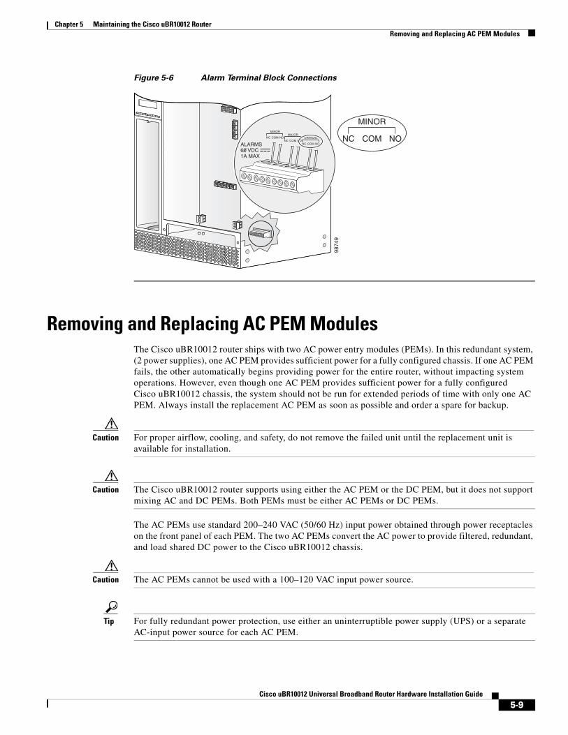
Removing the Half-Height Gigabit Ethernet Line Card and the Slot Splitter
This section describes how to properly remove and replace HHGE line cards and the slot splitter from the chassis. This section includes the following tasks:
• Removing a Half-Height Gigabit Ethernet Line Card, page 5-27
• Removing the Slot Splitter, page 5-30
Removing a Half-Height Gigabit Ethernet Line CardUse the following procedure to remove the HHGE line card from the slot splitter:
Step 1 Verify that you are properly grounded.
Step 2 Disconnect any network cables connected to the line card port.
5-27Cisco uBR10012 Universal Broadband Router Hardware Installation Guide

Chapter 5 Maintaining the Cisco uBR10012 RouterRemoving the Half-Height Gigabit Ethernet Line Card and the Slot Splitter
Figure 5-23 Captive Screw Locations
Step 3 Loosen the top and bottom captive screws until they disengage and spring away from the face plate (Figure 5-23).
Step 4 Simultaneously pivot both ejector levers away from each other to disengage the line card from the backplane (Figure 5-24).
Step 5 Slide the line card out of the slot splitter and place it on an antistatic surface or in an antistatic bag.
Step 6 If you are not installing a replacement line card, install a blank faceplate in the slot.
1351
54
US0
US1
US2
US3
US4
US5
US6
US7
US8
US9
US10
US11
US12
US13
US14
US15
US16
US17
US18
US19
DS0
DS1
DS2
DS3
DS4
RF
RF
RF
RF
RF
uB
R10-M
C5x2
0S
-D
POWER
STATUSM
AINT
US0
US1
US2
US3
US4
US5
US6
US7
US8
US9
US10
US11
US12
US13
US14
US15
US16
US17
US18
US19
DS0
DS1
DS2
DS3
DS4
RF
RF
RF
RF
RF
uB
R10-M
C5x2
0S
-D
POWER
STATUSM
AINT
US0
US1
US2
US3
US4
US5
US6
US7
US8
US9
US10
US11
US12
US13
US14
US15
US16
US17
US18
US19
DS0
DS1
DS2
DS3
DS4
RF
RF
RF
RF
RF
uB
R10-M
C5x2
0S
-D
POWER
STATUSM
AINT
US0
US1
US2
US3
US4
US5
US6
US7
US8
US9
US10
US11
US12
US13
US14
US15
US16
US17
US18
US19
DS0
DS1
DS2
DS3
DS4
RF
RF
RF
RF
RF
uB
R10-M
C5x2
0S
-D
POWER
STATUSM
AINT
US0
US1
US2
US3
US4
US5
US6
US7
US8
US9
US10
US11
US12
US13
US14
US15
US16
US17
US18
US19
DS0
DS1
DS2
DS3
DS4
RF
RF
RF
RF
RF
uB
R10-M
C5x2
0S
-D
POWER
STATUSM
AINT
US0
US1
US2
US3
US4
US5
US6
US7
US8
US9
US10
US11
US12
US13
US14
US15
US16
US17
US18
US19
DS0
DS1
DS2
DS3
DS4
RF
RF
RF
RF
RF
uB
R10-M
C5x2
0S
-D
POWER
STATUSM
AINT
US0
US1
US2
US3
US4
US5
US6
US7
US8
US9
US10
US11
US12
US13
US14
US15
US16
US17
US18
US19
DS0
DS1
DS2
DS3
DS4
RF
RF
RF
RF
RF
uB
R10-M
C5x2
0S
-D
POWER
STATUSM
AINT
US1
US2
US3
US4
US5
US6
US7
US8
US9
US10
US11
US12
US13
US14
US15
US16
US17
US18
US19
DS0
DS1
DS2
DS3
DS4
RF
RF
RF
RF
RF
uB
R10-M
C5x2
0S
-D
POWER
STATUSM
AINT
CISCO10000
CISCO10000
FAIL
LINK
CISCO10000
EN
AB
LE
PO
SS
RP
FA
IL
OC
–48/S
TM
–16 P
OS
/SR
P S
M–LR
CD TX
RX
SY
NC
WR
AP
PA
SS
TH
RU
TXRX
CISCO10000
EN
AB
LE
PO
SS
RP
FA
IL
OC
–48/S
TM
–16 P
OS
/SR
P S
M–LR
CD TX
RX
SY
NC
WR
AP
PA
SS
TH
RU
TXRX
Captive screw
Captive screw
5-28Cisco uBR10012 Universal Broadband Router Hardware Installation Guide

Chapter 5 Maintaining the Cisco uBR10012 RouterRemoving the Half-Height Gigabit Ethernet Line Card and the Slot Splitter
Figure 5-24 Opening the Ejector Levers
Caution Do not operate the system unless all slots contain a line card or a blank faceplate. Always install a full-slot blank faceplate into an empty slot. Half-height blank faceplates do not have air dams, and the empty slot will rob cooling air from the other slots. A slot splitter with one half-height line card and one blank faceplate is allowed.
Warning Blank faceplates and cover panels serve three important functions: they prevent exposure to hazardous voltages and currents inside the chassis; they contain electromagnetic interference (EMI) that might disrupt other equipment; and they direct the flow of cooling air through the chassis. Do not operate the system unless all cards, faceplates, front covers, and rear covers are in place. Statement 1029
1351
56
US0
US1
US2
US3
US4
US5
US6
US7
US8
US9
US10
US11
US12
US13
US14
US15
US16
US17
US18
US19
DS0
DS1
DS2
DS3
DS4
RF
RF
RF
RF
RF
uB
R10-M
C5x2
0S
-D
POWER
STATUSM
AINT
US0
US1
US2
US3
US4
US5
US6
US7
US8
US9
US10
US11
US12
US13
US14
US15
US16
US17
US18
US19
DS0
DS1
DS2
DS3
DS4
RF
RF
RF
RF
RF
uB
R10-M
C5x2
0S
-D
POWER
STATUSM
AINT
US0
US1
US2
US3
US4
US5
US6
US7
US8
US9
US10
US11
US12
US13
US14
US15
US16
US17
US18
US19
DS0
DS1
DS2
DS3
DS4
RF
RF
RF
RF
RF
uB
R10-M
C5x2
0S
-D
POWER
STATUSM
AINT
US0
US1
US2
US3
US4
US5
US6
US7
US8
US9
US10
US11
US12
US13
US14
US15
US16
US17
US18
US19
DS0
DS1
DS2
DS3
DS4
RF
RF
RF
RF
RF
uB
R10-M
C5x2
0S
-D
POWER
STATUSM
AINT
US0
US1
US2
US3
US4
US5
US6
US7
US8
US9
US10
US11
US12
US13
US14
US15
US16
US17
US18
US19
DS0
DS1
DS2
DS3
DS4
RF
RF
RF
RF
RF
uB
R10-M
C5x2
0S
-D
POWER
STATUSM
AINT
US0
US1
US2
US3
US4
US5
US6
US7
US8
US9
US10
US11
US12
US13
US14
US15
US16
US17
US18
US19
DS0
DS1
DS2
DS3
DS4
RF
RF
RF
RF
RF
uB
R10-M
C5x2
0S
-D
POWER
STATUSM
AINT
US0
US1
US2
US3
US4
US5
US6
US7
US8
US9
US10
US11
US12
US13
US14
US15
US16
US17
US18
US19
DS0
DS1
DS2
DS3
DS4
RF
RF
RF
RF
RF
uB
R10-M
C5x2
0S
-D
POWER
STATUSM
AINT
US0
US1
US2
US3
US4
US5
US6
US7
US8
US9
US10
US11
US12
US13
US14
US15
US16
US17
US18
US19
DS0
DS1
DS2
DS3
DS4
RF
RF
RF
RF
RF
uB
R10-M
C5x2
0S
-D
POWER
STATUSM
AINT
CISCO10000
CISCO10000
FAIL
LINK
CISCO10000
EN
AB
LE
PO
SS
RP
FA
IL
OC
–48/S
TM
–16 P
OS
/SR
P S
M–LR
CD TX
RX
SY
NC
WR
AP
PA
SS
TH
RU
TXRX
CISCO10000
EN
AB
LE
PO
SS
RP
FA
IL
OC
–48/S
TM
–16 P
OS
/SR
P S
M–LR
CD TX
RX
SY
NC
WR
AP
PA
SS
TH
RU
TXRX
CISCO10000
CISCO10000
FAIL
LINK
5-29Cisco uBR10012 Universal Broadband Router Hardware Installation Guide

Chapter 5 Maintaining the Cisco uBR10012 RouterRemoving the Half-Height Gigabit Ethernet Line Card and the Slot Splitter
Removing the Slot SplitterUse the following procedure to remove a slot splitter from the chassis:
Step 1 Attach an antistatic wrist strap to your wrist and to the ESD socket on the chassis, or to a bare metal surface on the chassis or frame).
Step 2 Remove any line cards from the splitter according to the “Removing a Half-Height Gigabit Ethernet Line Card” section on page 5-27.
The slot splitter does not have ejector levers to disengage cards from the backplane, so you must remove any line cards before you remove the splitter.
Step 3 Loosen the top and bottom captive screws on the slot splitter (Figure 5-25).
Figure 5-25 Captive Screw Locations
1351
50
US0
US1
US2
US3
US4
US5
US6
US7
US8
US9
US10
US11
US12
US13
US14
US15
US16
US17
US18
US19
DS0
DS1
DS2
DS3
DS4
RF
RF
RF
RF
RF
uB
R10-M
C5x2
0S
-D
POWER
STATUSM
AINT
US0
US1
US2
US3
US4
US5
US6
US7
US8
US9
US10
US11
US12
US13
US14
US15
US16
US17
US18
US19
DS0
DS1
DS2
DS3
DS4
RF
RF
RF
RF
RF
uB
R10-M
C5x2
0S
-D
POWER
STATUSM
AINT
US0
US1
US2
US3
US4
US5
US6
US7
US8
US9
US10
US11
US12
US13
US14
US15
US16
US17
US18
US19
DS0
DS1
DS2
DS3
DS4
RF
RF
RF
RF
RF
uB
R10-M
C5x2
0S
-D
POWER
STATUSM
AINT
US0
US1
US2
US3
US4
US5
US6
US7
US8
US9
US10
US11
US12
US13
US14
US15
US16
US17
US18
US19
DS0
DS1
DS2
DS3
DS4
RF
RF
RF
RF
RF
uB
R10-M
C5x2
0S
-D
POWER
STATUSM
AINT
US0
US1
US2
US3
US4
US5
US6
US7
US8
US9
US10
US11
US12
US13
US14
US15
US16
US17
US18
US19
DS0
DS1
DS2
DS3
DS4
RF
RF
RF
RF
RF
uB
R10-M
C5x2
0S
-D
POWER
STATUSM
AINT
US0
US1
US2
US3
US4
US5
US6
US7
US8
US9
US10
US11
US12
US13
US14
US15
US16
US17
US18
US19
DS0
DS1
DS2
DS3
DS4
RF
RF
RF
RF
RF
uB
R10-M
C5x2
0S
-D
POWER
STATUSM
AINT
US0
US1
US2
US3
US4
US5
US6
US7
US8
US9
US10
US11
US12
US13
US14
US15
US16
US17
US18
US19
DS0
DS1
DS2
DS3
DS4
RF
RF
RF
RF
RF
uB
R10-M
C5x2
0S
-D
POWER
STATUSM
AINT
US0
US1
US2
US3
US4
US5
US6
US7
US8
US9
US10
US11
US12
US13
US14
US15
US16
US17
US18
US19
DS0
DS1
DS2
DS3
DS4
RF
RF
RF
RF
RF
uB
R10-M
C5x2
0S
-D
POWER
STATUSM
AINT
CISCO10000
CISCO10000
EN
AB
LE
PO
SS
RP
FA
IL
OC
–48/S
TM
–16 P
OS
/SR
P S
M–LR
CD TX
RX
SY
NC
WR
AP
PA
SS
TH
RU
TXRX
CISCO10000
EN
AB
LE
PO
SS
RP
FA
IL
OC
–48/S
TM
–16 P
OS
/SR
P S
M–LR
CD TX
RX
SY
NC
WR
AP
PA
SS
TH
RU
TXRX
Captivescrew
Captivescrew
5-30Cisco uBR10012 Universal Broadband Router Hardware Installation Guide

Chapter 5 Maintaining the Cisco uBR10012 RouterRemoving the Half-Height Gigabit Ethernet Line Card and the Slot Splitter
Step 4 Slide the splitter out of the slot (Figure 5-26).
Step 5 If you are not installing a replacement splitter or a line card, install a full-slot blank faceplate in the slot.
Figure 5-26 Removing the Slot Splitter
1351
57
US0
US1
US2
US3
US4
US5
US6
US7
US8
US9
US10
US11
US12
US13
US14
US15
US16
US17
US18
US19
DS0
DS1
DS2
DS3
DS4
RF
RF
RF
RF
RF
uB
R10-M
C5x2
0S
-D
POWER
STATUSM
AINT
US0
US1
US2
US3
US4
US5
US6
US7
US8
US9
US10
US11
US12
US13
US14
US15
US16
US17
US18
US19
DS0
DS1
DS2
DS3
DS4
RF
RF
RF
RF
RF
uB
R10-M
C5x2
0S
-D
POWER
STATUSM
AINT
US0
US1
US2
US3
US4
US5
US6
US7
US8
US9
US10
US11
US12
US13
US14
US15
US16
US17
US18
US19
DS0
DS1
DS2
DS3
DS4
RF
RF
RF
RF
RF
uB
R10-M
C5x2
0S
-D
POWER
STATUSM
AINT
US0
US1
US2
US3
US4
US5
US6
US7
US8
US9
US10
US11
US12
US13
US14
US15
US16
US17
US18
US19
DS0
DS1
DS2
DS3
DS4
RF
RF
RF
RF
RF
uB
R10-M
C5x2
0S
-D
POWER
STATUSM
AINT
US0
US1
US2
US3
US4
US5
US6
US7
US8
US9
US10
US11
US12
US13
US14
US15
US16
US17
US18
US19
DS0
DS1
DS2
DS3
DS4
RF
RF
RF
RF
RF
uB
R10-M
C5x2
0S
-D
POWER
STATUSM
AINT
US0
US1
US2
US3
US4
US5
US6
US7
US8
US9
US10
US11
US12
US13
US14
US15
US16
US17
US18
US19
DS0
DS1
DS2
DS3
DS4
RF
RF
RF
RF
RF
uB
R10-M
C5x2
0S
-D
POWER
STATUSM
AINT
US0
US1
US2
US3
US4
US5
US6
US7
US8
US9
US10
US11
US12
US13
US14
US15
US16
US17
US18
US19
DS0
DS1
DS2
DS3
DS4
RF
RF
RF
RF
RF
uB
R10-M
C5x2
0S
-D
POWER
STATUSM
AINT
US0
US1
US2
US3
US4
US5
US6
US7
US8
US9
US10
US11
US12
US13
US14
US15
US16
US17
US18
US19
DS0
DS1
DS2
DS3
DS4
RF
RF
RF
RF
RF
uB
R10-M
C5x2
0S
-D
POWER
STATUSM
AINT
CISCO10000
CISCO10000
EN
AB
LE
PO
SS
RP
FA
IL
OC
–48/S
TM
–16 P
OS
/SR
P S
M–LR
CD TX
RX
SY
NC
WR
AP
PA
SS
TH
RU
TXRX
CISCO10000
EN
AB
LE
PO
SS
RP
FA
IL
OC
–48/S
TM
–16 P
OS
/SR
P S
M–LR
CD TX
RX
SY
NC
WR
AP
PA
SS
TH
RU
TXRX
5-31Cisco uBR10012 Universal Broadband Router Hardware Installation Guide

Chapter 5 Maintaining the Cisco uBR10012 RouterReplacing the Slot Splitter and Half-Height Gigabit Ethernet Line Card
Replacing the Slot Splitter and Half-Height Gigabit Ethernet Line Card
This section describes how to install the line card in the Cisco uBR10012 router. This section includes the following tasks:
• Installing the Slot Splitter, page 5-32
• Installing the Half-Height Gigabit Ethernet Line Card, page 5-35
Caution You must use slot 3 or slot 4 when installing the slot splitter and HHGE line card in the Cisco uBR10012 router, using slot 1 or slot 2 will cause the router to shut down those slots.
Caution Do not install two half-height blank faceplates into the same slot in the slot splitter. Instead, install a full-slot blank faceplate into the slot. The half-height blank faceplates do not have air dams, and the empty slot will rob cooling air from the other slots. A slot splitter with one half-height line card and one blank faceplate is allowed.
Caution Do not install a line card into the slot splitter before installing the splitter into the chassis. The slot splitter does not have ejector levers that allow you to seat the line card in the backplane.
Installing the Slot SplitterYou must install the half-height line card into a slot that contains a slot splitter, which can hold two half-height line cards. If both slots of the slot splitter are not used, then you must install a blank faceplate in the empty slot.
Follow these steps to install a slot splitter into slot 3 or slot 4 of the Cisco uBR10012 chassis.
Step 1 Attach an antistatic wrist strap to your wrist and to an ESD socket on the chassis, or to a bare metal surface on the chassis or frame (Figure 5-21).
5-32Cisco uBR10012 Universal Broadband Router Hardware Installation Guide
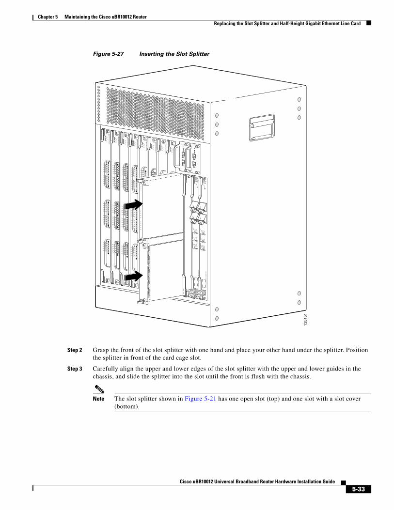
Chapter 5 Maintaining the Cisco uBR10012 RouterReplacing the Slot Splitter and Half-Height Gigabit Ethernet Line Card
Figure 5-27 Inserting the Slot Splitter
Step 2 Grasp the front of the slot splitter with one hand and place your other hand under the splitter. Position the splitter in front of the card cage slot.
Step 3 Carefully align the upper and lower edges of the slot splitter with the upper and lower guides in the chassis, and slide the splitter into the slot until the front is flush with the chassis.
Note The slot splitter shown in Figure 5-21 has one open slot (top) and one slot with a slot cover (bottom).
1351
51
US0
US1
US2
US3
US4
US5
US6
US7
US8
US9
US10
US11
US12
US13
US14
US15
US16
US17
US18
US19
DS0
DS1
DS2
DS3
DS4
RF
RF
RF
RF
RF
uB
R10-M
C5x2
0S
-D
POWER
STATUSM
AINT
US0
US1
US2
US3
US4
US5
US6
US7
US8
US9
US10
US11
US12
US13
US14
US15
US16
US17
US18
US19
DS0
DS1
DS2
DS3
DS4
RF
RF
RF
RF
RF
uB
R10-M
C5x2
0S
-D
POWER
STATUSM
AINT
US0
US1
US2
US3
US4
US5
US6
US7
US8
US9
US10
US11
US12
US13
US14
US15
US16
US17
US18
US19
DS0
DS1
DS2
DS3
DS4
RF
RF
RF
RF
RF
uB
R10-M
C5x2
0S
-D
POWER
STATUSM
AINT
US0
US1
US2
US3
US4
US5
US6
US7
US8
US9
US10
US11
US12
US13
US14
US15
US16
US17
US18
US19
DS0
DS1
DS2
DS3
DS4
RF
RF
RF
RF
RF
uB
R10-M
C5x2
0S
-D
POWER
STATUSM
AINT
US0
US1
US2
US3
US4
US5
US6
US7
US8
US9
US10
US11
US12
US13
US14
US15
US16
US17
US18
US19
DS0
DS1
DS2
DS3
DS4
RF
RF
RF
RF
RF
uB
R10-M
C5x2
0S
-D
POWER
STATUSM
AINT
US0
US1
US2
US3
US4
US5
US6
US7
US8
US9
US10
US11
US12
US13
US14
US15
US16
US17
US18
US19
DS0
DS1
DS2
DS3
DS4
RF
RF
RF
RF
RF
uB
R10-M
C5x2
0S
-D
POWER
STATUSM
AINT
US0
US1
US2
US3
US4
US5
US6
US7
US8
US9
US10
US11
US12
US13
US14
US15
US16
US17
US18
US19
DS0
DS1
DS2
DS3
DS4
RF
RF
RF
RF
RF
uB
R10-M
C5x2
0S
-D
POWER
STATUSM
AINT
US0
US1
US2
US3
US4
US5
US6
US7
US8
US9
US10
US11
US12
US13
US14
US15
US16
US17
US18
US19
DS0
DS1
DS2
DS3
DS4
RF
RF
RF
RF
RF
uB
R10-M
C5x2
0S
-D
POWER
STATUSM
AINT
CISCO10000
CISCO10000
EN
AB
LE
PO
SS
RP
FA
IL
OC
–48/S
TM
–16 P
OS
/SR
P S
M–LR
CD TX
RX
SY
NC
WR
AP
PA
SS
TH
RU
TXRX
CISCO10000
EN
AB
LE
PO
SS
RP
FA
IL
OC
–48/S
TM
–16 P
OS
/SR
P S
M–LR
CD TX
RX
SY
NC
WR
AP
PA
SS
TH
RU
TXRX
5-33Cisco uBR10012 Universal Broadband Router Hardware Installation Guide

Chapter 5 Maintaining the Cisco uBR10012 RouterReplacing the Slot Splitter and Half-Height Gigabit Ethernet Line Card
Figure 5-28 Captive Screw Locations
Step 4 Secure the slot splitter to the chassis by tightening the top and bottom captive screws (Figure 5-28).
Warning Blank faceplates and cover panels serve three important functions: they prevent exposure to hazardous voltages and currents inside the chassis; they contain electromagnetic interference (EMI) that might disrupt other equipment; and they direct the flow of cooling air through the chassis. Do not operate the system unless all cards, faceplates, front covers, and rear covers are in place. Statement 1029
1351
50
US0
US1
US2
US3
US4
US5
US6
US7
US8
US9
US10
US11
US12
US13
US14
US15
US16
US17
US18
US19
DS0
DS1
DS2
DS3
DS4
RF
RF
RF
RF
RF
uB
R10-M
C5x2
0S
-D
POWER
STATUSM
AINT
US0
US1
US2
US3
US4
US5
US6
US7
US8
US9
US10
US11
US12
US13
US14
US15
US16
US17
US18
US19
DS0
DS1
DS2
DS3
DS4
RF
RF
RF
RF
RF
uB
R10-M
C5x2
0S
-D
POWER
STATUSM
AINT
US0
US1
US2
US3
US4
US5
US6
US7
US8
US9
US10
US11
US12
US13
US14
US15
US16
US17
US18
US19
DS0
DS1
DS2
DS3
DS4
RF
RF
RF
RF
RF
uB
R10-M
C5x2
0S
-D
POWER
STATUSM
AINT
US0
US1
US2
US3
US4
US5
US6
US7
US8
US9
US10
US11
US12
US13
US14
US15
US16
US17
US18
US19
DS0
DS1
DS2
DS3
DS4
RF
RF
RF
RF
RF
uB
R10-M
C5x2
0S
-D
POWER
STATUSM
AINT
US0
US1
US2
US3
US4
US5
US6
US7
US8
US9
US10
US11
US12
US13
US14
US15
US16
US17
US18
US19
DS0
DS1
DS2
DS3
DS4
RF
RF
RF
RF
RFuB
R10-M
C5x2
0S
-D
POWER
STATUSM
AINT
US0
US1
US2
US3
US4
US5
US6
US7
US8
US9
US10
US11
US12
US13
US14
US15
US16
US17
US18
US19
DS0
DS1
DS2
DS3
DS4
RF
RF
RF
RF
RF
uB
R10-M
C5x2
0S
-D
POWER
STATUSM
AINT
US0
US1
US2
US3
US4
US5
US6
US7
US8
US9
US10
US11
US12
US13
US14
US15
US16
US17
US18
US19
DS0
DS1
DS2
DS3
DS4
RF
RF
RF
RF
RF
uB
R10-M
C5x2
0S
-D
POWER
STATUSM
AINT
US0
US1
US2
US3
US4
US5
US6
US7
US8
US9
US10
US11
US12
US13
US14
US15
US16
US17
US18
US19
DS0
DS1
DS2
DS3
DS4
RF
RF
RF
RF
RF
uB
R10-M
C5x2
0S
-D
POWER
STATUSM
AINT
CISCO10000
CISCO10000
EN
AB
LE
PO
SS
RP
FA
IL
OC
–48/S
TM
–16 P
OS
/SR
P S
M–LR
CD TX
RX
SY
NC
WR
AP
PA
SS
TH
RU
TXRX
CISCO10000
EN
AB
LE
PO
SS
RP
FA
IL
OC
–48/S
TM
–16 P
OS
/SR
P S
M–LR
CD TX
RX
SY
NC
WR
AP
PA
SS
TH
RU
TXRX
Captivescrew
Captivescrew
5-34Cisco uBR10012 Universal Broadband Router Hardware Installation Guide

Chapter 5 Maintaining the Cisco uBR10012 RouterReplacing the Slot Splitter and Half-Height Gigabit Ethernet Line Card
Installing the Half-Height Gigabit Ethernet Line CardUse the following procedure to install a HHGE line card into an installed slot splitter. See the “Installing the Slot Splitter” section on page 5-32 to install the slot splitter.
If you are replacing a line card, see the “Removing a Half-Height Gigabit Ethernet Line Card” section on page 5-27 before you begin this procedure.
Step 1 Attach an antistatic wrist strap to your wrist and to an ESD socket on the chassis, or to a bare metal surface on the chassis or frame.
Figure 5-29 Inserting the Line Card
Step 2 Grasp the faceplate of the line card with one hand and place your other hand under the card carrier (to support the weight of the card). Position the card in front of the slot splitter.
Step 3 Carefully align the upper and lower edges of the line card with the upper and lower guides in the slot splitter, and slide the line card about half-way into the splitter.
1351
52
US0
US1
US2
US3
US4
US5
US6
US7
US8
US9
US10
US11
US12
US13
US14
US15
US16
US17
US18
US19
DS0
DS1
DS2
DS3
DS4
RF
RF
RF
RF
RF
uB
R10-M
C5x2
0S
-D
POWER
STATUSM
AINT
US0
US1
US2
US3
US4
US5
US6
US7
US8
US9
US10
US11
US12
US13
US14
US15
US16
US17
US18
US19
DS0
DS1
DS2
DS3
DS4
RF
RF
RF
RF
RF
uB
R10-M
C5x2
0S
-D
POWER
STATUSM
AINT
US0
US1
US2
US3
US4
US5
US6
US7
US8
US9
US10
US11
US12
US13
US14
US15
US16
US17
US18
US19
DS0
DS1
DS2
DS3
DS4
RF
RF
RF
RF
RF
uB
R10-M
C5x2
0S
-D
POWER
STATUSM
AINT
US0
US1
US2
US3
US4
US5
US6
US7
US8
US9
US10
US11
US12
US13
US14
US15
US16
US17
US18
US19
DS0
DS1
DS2
DS3
DS4
RF
RF
RF
RF
RF
uB
R10-M
C5x2
0S
-D
POWER
STATUSM
AINT
US0
US1
US2
US3
US4
US5
US6
US7
US8
US9
US10
US11
US12
US13
US14
US15
US16
US17
US18
US19
DS0
DS1
DS2
DS3
DS4
RF
RF
RF
RF
RF
uB
R10-M
C5x2
0S
-D
POWER
STATUSM
AINT
US0
US1
US2
US3
US4
US5
US6
US7
US8
US9
US10
US11
US12
US13
US14
US15
US16
US17
US18
US19
DS0
DS1
DS2
DS3
DS4
RF
RF
RF
RF
RF
uB
R10-M
C5x2
0S
-D
POWER
STATUSM
AINT
US0
US1
US2
US3
US4
US5
US6
US7
US8
US9
US10
US11
US12
US13
US14
US15
US16
US17
US18
US19
DS0
DS1
DS2
DS3
DS4
RF
RF
RF
RF
RF
uB
R10-M
C5x2
0S
-D
POWER
STATUSM
AINT
US0
US1
US2
US3
US4
US5
US6
US7
US8
US9
US10
US11
US12
US13
US14
US15
US16
US17
US18
US19
DS0
DS1
DS2
DS3
DS4
RF
RF
RF
RF
RF
uB
R10-M
C5x2
0S
-D
POWER
STATUSM
AINT
CISCO10000
CISCOCISCO1000010000
FAIL
AIL
LINK
LINK
Ejectorlever CISCO
10000
FAIL
LINK
CISCO10000
EN
AB
LE
PO
SS
RP
FA
IL
OC
–48/S
TM
–16 P
OS
/SR
P S
M–LR
CD TX
RX
SY
NC
WR
AP
PA
SS
TH
RU
TXRX
CISCO10000
EN
AB
LE
PO
SS
RP
FA
IL
OC
–48/S
TM
–16 P
OS
/SR
P S
M–LR
CD TX
RX
SY
NC
WR
AP
PA
SS
TH
RU
TXRX
Ejectorlever
Ejectorlever
5-35Cisco uBR10012 Universal Broadband Router Hardware Installation Guide

Chapter 5 Maintaining the Cisco uBR10012 RouterReplacing the Slot Splitter and Half-Height Gigabit Ethernet Line Card
Step 4 Be sure the ejectors are in the open position (as shown) and continue to push the line card into the splitter until you can feel it begin to seat in the backplane connectors.
Step 5 Verify that the captive screws are properly aligned with the captive screw holes in the splitter. If the captive screws are not properly aligned, the card will not seat properly in the backplane.
Step 6 Simultaneously pivot both ejector levers toward each other (until they are parallel to the faceplate) to firmly seat the card in the backplane (Figure 5-22).
The line card cycles through its power-on self-test. The FAIL LED lights during portions of the POST (Power-On Self Test), but remains off after POST on a properly working line card. If the FAIL LED remains on, go to the “Troubleshooting the HHGE Installation” section on page 4-17.
Figure 5-30 Closing the Ejector Levers
1351
53
US0
US1
US2
US3
US4
US5
US6
US7
US8
US9
US10
US11
US12
US13
US14
US15
US16
US17
US18
US19
DS0
DS1
DS2
DS3
DS4
RF
RF
RF
RF
RF
uB
R10-M
C5x2
0S
-D
POWER
STATUSM
AINT
US0
US1
US2
US3
US4
US5
US6
US7
US8
US9
US10
US11
US12
US13
US14
US15
US16
US17
US18
US19
DS0
DS1
DS2
DS3
DS4
RF
RF
RF
RF
RF
uB
R10-M
C5x2
0S
-D
POWER
STATUSM
AINT
US0
US1
US2
US3
US4
US5
US6
US7
US8
US9
US10
US11
US12
US13
US14
US15
US16
US17
US18
US19
DS0
DS1
DS2
DS3
DS4
RF
RF
RF
RF
RF
uB
R10-M
C5x2
0S
-D
POWER
STATUSM
AINT
US0
US1
US2
US3
US4
US5
US6
US7
US8
US9
US10
US11
US12
US13
US14
US15
US16
US17
US18
US19
DS0
DS1
DS2
DS3
DS4
RF
RF
RF
RF
RF
uB
R10-M
C5x2
0S
-D
POWER
STATUSM
AINT
US0
US1
US2
US3
US4
US5
US6
US7
US8
US9
US10
US11
US12
US13
US14
US15
US16
US17
US18
US19
DS0
DS1
DS2
DS3
DS4
RF
RF
RF
RF
RF
uB
R10-M
C5x2
0S
-D
POWER
STATUSM
AINT
US0
US1
US2
US3
US4
US5
US6
US7
US8
US9
US10
US11
US12
US13
US14
US15
US16
US17
US18
US19
DS0
DS1
DS2
DS3
DS4
RF
RF
RF
RF
RF
uB
R10-M
C5x2
0S
-D
POWER
STATUSM
AINT
US0
US1
US2
US3
US4
US5
US6
US7
US8
US9
US10
US11
US12
US13
US14
US15
US16
US17
US18
US19
DS0
DS1
DS2
DS3
DS4
RF
RF
RF
RF
RF
uB
R10-M
C5x2
0S
-D
POWER
STATUSM
AINT
US0
US1
US2
US3
US4
US5
US6
US7
US8
US9
US10
US11
US12
US13
US14
US15
US16
US17
US18
US19
DS0
DS1
DS2
DS3
DS4
RF
RF
RF
RF
RF
uB
R10-M
C5x2
0S
-D
POWER
STATUSM
AINT
CISCO10000
CISCO10000
FAIL
LINK
CISCO10000
EN
AB
LE
PO
SS
RP
FA
IL
OC
–48/S
TM
–16 P
OS
/SR
P S
M–LR
CD TX
RX
SY
NC
WR
AP
PA
SS
TH
RU
TXRX
CISCO10000
EN
AB
LE
PO
SS
RP
FA
IL
OC
–48/S
TM
–16 P
OS
/SR
P S
M–LR
CD TX
RX
SY
NC
WR
AP
PA
SS
TH
RU
TXRX
CISCO10000
CISCO10000
FAIL
LINK
5-36Cisco uBR10012 Universal Broadband Router Hardware Installation Guide

Chapter 5 Maintaining the Cisco uBR10012 RouterReplacing the Slot Splitter and Half-Height Gigabit Ethernet Line Card
Figure 5-31 Captive Screw Locations
Step 7 Secure the line card in the slot splitter by tightening the top and bottom captive screws (Figure 5-31).
Caution To ensure that there is adequate space for additional line cards, always tighten the captive screws on each newly installed line card before you insert any additional line cards. These screws prevent accidental removal and provide proper grounding for electromagnetic interference (EMI) shielding.
1351
54
US0
US1
US2
US3
US4
US5
US6
US7
US8
US9
US10
US11
US12
US13
US14
US15
US16
US17
US18
US19
DS0
DS1
DS2
DS3
DS4
RF
RF
RF
RF
RF
uB
R10-M
C5x2
0S
-D
POWER
STATUSM
AINT
US0
US1
US2
US3
US4
US5
US6
US7
US8
US9
US10
US11
US12
US13
US14
US15
US16
US17
US18
US19
DS0
DS1
DS2
DS3
DS4
RF
RF
RF
RF
RF
uB
R10-M
C5x2
0S
-D
POWER
STATUSM
AINT
US0
US1
US2
US3
US4
US5
US6
US7
US8
US9
US10
US11
US12
US13
US14
US15
US16
US17
US18
US19
DS0
DS1
DS2
DS3
DS4
RF
RF
RF
RF
RF
uB
R10-M
C5x2
0S
-D
POWER
STATUSM
AINT
US0
US1
US2
US3
US4
US5
US6
US7
US8
US9
US10
US11
US12
US13
US14
US15
US16
US17
US18
US19
DS0
DS1
DS2
DS3
DS4
RF
RF
RF
RF
RF
uB
R10-M
C5x2
0S
-D
POWER
STATUSM
AINT
US0
US1
US2
US3
US4
US5
US6
US7
US8
US9
US10
US11
US12
US13
US14
US15
US16
US17
US18
US19
DS0
DS1
DS2
DS3
DS4
RF
RF
RF
RF
RF
uB
R10-M
C5x2
0S
-D
POWER
STATUSM
AINT
US0
US1
US2
US3
US4
US5
US6
US7
US8
US9
US10
US11
US12
US13
US14
US15
US16
US17
US18
US19
DS0
DS1
DS2
DS3
DS4
RF
RF
RF
RF
RF
uB
R10-M
C5x2
0S
-D
POWER
STATUSM
AINT
US0
US1
US2
US3
US4
US5
US6
US7
US8
US9
US10
US11
US12
US13
US14
US15
US16
US17
US18
US19
DS0
DS1
DS2
DS3
DS4
RF
RF
RF
RF
RF
uB
R10-M
C5x2
0S
-D
POWER
STATUSM
AINT
US1
US2
US3
US4
US5
US6
US7
US8
US9
US10
US11
US12
US13
US14
US15
US16
US17
US18
US19
DS0
DS1
DS2
DS3
DS4
RF
RF
RF
RF
RF
uB
R10-M
C5x2
0S
-D
POWER
STATUSM
AINT
CISCO10000
CISCO10000
FAIL
LINK
CISCO10000
EN
AB
LE
PO
SS
RP
FA
IL
OC
–48/S
TM
–16 P
OS
/SR
P S
M–LR
CD TX
RX
SY
NC
WR
AP
PA
SS
TH
RU
TXRX
CISCO10000
EN
AB
LE
PO
SS
RP
FA
IL
OC
–48/S
TM
–16 P
OS
/SR
P S
M–LR
CD TX
RX
SY
NC
WR
AP
PA
SS
TH
RU
TXRX
Captive screw
Captive screw
5-37Cisco uBR10012 Universal Broadband Router Hardware Installation Guide

Chapter 5 Maintaining the Cisco uBR10012 RouterRemoving and Replacing an SFP Module
Removing and Replacing an SFP ModuleYour HHGE line card is shipped with an SFP module installed. Use the procedures in this section if you need to change the SFP module:
• Removing an SFP Module, page 5-38
• Inserting an SFP Module, page 5-40
Use only SFP modules supplied by Cisco with your HHGE line card. Each SFP module contains an internal serial EEPROM that is security-programmed by the SFP manufacturer with information that provides a way for Cisco (through Cisco IOS software) to identify and validate the SFP module as a module type that is tested and qualified by Cisco to operate properly with your line card. Unapproved SFP modules (those not purchased directly from Cisco) do not work with the HHGE line card.
Types of SFP ModulesSFP modules from different manufacturers provide different methods for freeing the locking pin and removing the SFP module. Figure 5-32 shows two available module types.
Figure 5-32 Mylar Tab SFP Module and Bale Clasp SFP Module
• Mylar Tab SFP—Pulling the mylar tab simultaneously releases the locking pin and pulls the SFP module out of its receptacle.
• Bale Clasp SFP—Opening the bale clasp releases the locking pin so you can remove the SFP module from its receptacle.
Removing an SFP ModuleUse the following procedure to remove an SFP module from the HHGE line card.
Note You can remove an SFP module while the system is powered on, but the interface shuts down.
Step 1 Attach an antistatic wrist strap to your wrist and to an ESD socket on the chassis, or to a bare metal surface on the chassis or frame.
Mylar tab Bale clasp 7641
5
5-38Cisco uBR10012 Universal Broadband Router Hardware Installation Guide

Chapter 5 Maintaining the Cisco uBR10012 RouterRemoving and Replacing an SFP Module
Figure 5-33 Disconnecting the LC-type Fiber-Optic Cable
Step 2 Disconnect the fiber-optic cable connector from the SFP module (Figure 5-33).
Note which cable connector plug is TX and which is RX for reattachment.
Figure 5-34 Removing an SFP Module
CISCO10000
FAIL
LINK
TX
0
RX
GIG
AB
IT E
TH
ER
NE
T
7641
6
GIG
AB
IT E
TH
ER
NE
T
GIG
AB
IT E
TH
ER
NE
T
GIG
AB
IT E
TH
ER
NE
T
1351
551 2
5-39Cisco uBR10012 Universal Broadband Router Hardware Installation Guide

Chapter 5 Maintaining the Cisco uBR10012 RouterRemoving and Replacing an SFP Module
Step 3 Unlock and remove the SFP module as follows:
a. Mylar Tab SFP Modules—Gently, but firmly pull the plastic tab to free the locking pin and remove the SFP module (Figure 5-34).
Caution Do not twist the Mylar tab when you remove the SFP module. Twisting the tab may disconnect it from the module.
b. Bale Clasp Modules—Open the bale clasp to release the locking pin and remove the SFP module (Figure 5-34).
Step 4 Insert a dust plug into the optical ports of the removed SFP module to keep the optical interfaces clean, and place the module in an antistatic bag or other protective environment.
Inserting an SFP ModuleUse the following procedure to insert an SFP module into the HHGE line card.
Step 1 Attach an antistatic wrist strap to your wrist and to an ESD socket on the chassis, or to a bare metal surface on the chassis or frame.
Figure 5-35 Inserting the SFP Module
CISCO10000
FAIL
LINK
TX
0
RX
GIG
AB
IT E
TH
ER
NE
T
7641
9
Dust plug
5-40Cisco uBR10012 Universal Broadband Router Hardware Installation Guide

Chapter 5 Maintaining the Cisco uBR10012 RouterUpgrading to a Half-Height Gigabit Ethernet Line Card
Step 2 Gently insert the SFP module into the line card port until the edge connector is fully seated in the connector. You will hear a click as the triangular pin on the bottom of the SFP module snaps into place (Figure 5-35).
Step 3 Remove the dust plug from the SFP module optical ports and plug the LC-type fiber-optic cable connector into the SFP module (see Figure 5-35).
Upgrading to a Half-Height Gigabit Ethernet Line CardThis section provides instructions for upgrading from two full height Gigabit Ethernet line cards to half-height Gigabit Ethernet line cards.
Note Verify that you have a PRE2 installed in the router and that you are using the latest IOS software, IOS software release 12.3(13)BC or later.
To upgrade from the full-height GigE line card to the HHGE line card, perform the following steps:
Step 1 Verify traffic is passing through slot 3 and slot 4.
Step 2 Administratively shut down the line card in slot 3 and let traffic reroute through slot 4.
Step 3 Remove the full height line card in slot 3.
Step 4 Install the slot splitter into slot 3.
Step 5 Install the half height card in the slot splitter 3/0/0 or slot 3/1/0.
Step 6 Configure and bring up the ethernet card in slot 3/0/0 or slot 3/1/0.
Refer to Configuring the Half-Height Gigabit Ethernet Line Card for the Cisco uBR10012 Universal Broadband Router at the following URL:
http://www.cisco.com/en/US/docs/interfaces_modules/cable/line_cards/ubr_hh_ge/configuration/guide/hhgefm10.html
Step 7 Repeat this procedure for the GigE line card in slot 4.
Removing and Replacing a Cable Interface Line CardUse the following procedure to install a new cable interface line card, or to remove or replace an existing cable interface line card in the Cisco uBR10012 chassis. The following cable interface line cards are supported:
• Cisco uBR10-MC5X20S/U, UBR10-MC5X20S=, UBR10-MC5X20U=
• Cisco UBR-MC20X20V, UBR-MC20X20V-20D=, UBR-MC20X20V-5D=, UBR-MC20X20V-0D=
• Cisco uBR-MC3GX60V, uBR-MC3GX60V=
5-41Cisco uBR10012 Universal Broadband Router Hardware Installation Guide

Chapter 5 Maintaining the Cisco uBR10012 RouterRemoving and Replacing a Cable Interface Line Card
Tip To prevent alarms from activating, you must administratively shut down a cable interface line card before hot-swapping it. Otherwise, inform the network administrator that this portion of the network will be temporarily interrupted. If the maintenance LED is lighted, you can remove the line card without affecting systems operations.
Removing the Cable Interface Line Card
Step 1 Attach an antistatic wrist strap to your wrist and to a bare metal, unpainted surface on the chassis or frame.
Step 2 Face the back of the Cisco uBR10012 chassis. Clear aside enough interface and power cables to allow sufficient space to work.
Step 3 If installing a new cable interface line card in a blank slot, remove the blank slot cover and discard. Otherwise, disconnect all coaxial cables from the cable interface line card being replaced or removed.
Step 4 Unscrew the top and bottom captive screws on the cable interface line card (see Figure 5-36).
5-42Cisco uBR10012 Universal Broadband Router Hardware Installation Guide

Chapter 5 Maintaining the Cisco uBR10012 RouterRemoving and Replacing a Cable Interface Line Card
Figure 5-36 Captive Screws, Ejector Levers
Step 5 Simultaneously pivot both ejector levers away from each other to disengage the cable interface line card from the backplane.
Step 6 Slide the cable interface line card out of the slot and place it on an antistatic surface, or in an antistatic bag (see Figure 5-37).
7250
8
US0
US1
US2
US3
US4
US5
US6
US7
US8
US9
US10
US11
US12
US13
US14
US15
US16
US17
US18
US19
DS0
DS1
DS2
DS3
DS4
RF
RF
RF
RF
RF
uB
R10-M
C5x2
0S
-D
POWER
STATUSM
AINT
US0
US1
US2
US3
US4
US5
US6
US7
US8
US9
US10
US11
US12
US13
US14
US15
US16
US17
US18
US19
DS0
DS1
DS2
DS3
DS4
RF
RF
RF
RF
RF
uB
R10-M
C5x2
0S
-D
POWER
STATUSM
AINT
US0
US1
US2
US3
US4
US5
US6
US7
US8
US9
US10
US11
US12
US13
US14
US15
US16
US17
US18
US19
DS0
DS1
DS2
DS3
DS4
RF
RF
RF
RF
RF
uB
R10-M
C5x2
0S
-D
POWER
STATUSM
AINT
US0
US1
US2
US3
US4
US5
US6
US7
US8
US9
US10
US11
US12
US13
US14
US15
US16
US17
US18
US19
DS0
DS1
DS2
DS3
DS4
RF
RF
RF
RF
RF
uB
R10-M
C5x2
0S
-D
POWER
STATUSM
AINT
CISCO10000
EN
AB
LE
PO
SS
RP
FA
IL
OC
–48/S
TM
–16 P
OS
/SR
P S
M–LR
CD TX
RX
SY
NC
WR
AP
PA
SS
TH
RU
TXRX
CISCO10000
EN
AB
LE
PO
SS
RP
FA
IL
OC
–48/S
TM
–16 P
OS
/SR
P S
M–LR
CD TX
RX
SY
NC
WR
AP
PA
SS
TH
RU
TXRX
CISCO10000
EN
AB
LE
PO
SS
RP
FA
IL
OC
–48/S
TM
–16 P
OS
/SR
P S
M–LR
CD TX
RX
SY
NC
WR
AP
PA
SS
TH
RU
TXRX
CISCO10000
EN
AB
LE
PO
SS
RP
FA
IL
OC
–48/S
TM
–16 P
OS
/SR
P S
M–LR
CD TX
RX
SY
NC
WR
AP
PA
SS
TH
RU
TXRX
US0
US1
US2
US3
US4
US5
US6
US7
US8
US9
US10
US11
US12
US13
US14
US15
US16
US17
US18
US19
DS0
DS1
DS2
DS3
DS4
RF
RF
RF
RF
RF
uB
R10-M
C5x2
0S
-D
POWER
STATUSM
AINT
US0
US1
US2
US3
US4
US5
US6
US7
US8
US9
US10
US11
US12
US13
US14
US15
US16
US17
US18
US19
DS0
DS1
DS2
DS3
DS4
RF
RF
RF
RF
RF
uB
R10-M
C5x2
0S
-D
POWER
STATUSM
AINT
US0
US1
US2
US3
US4
US5
US6
US7
US8
US9
US10
US11
US12
US13
US14
US15
US16
US17
US18
US19
DS0
DS1
DS2
DS3
DS4
RF
RF
RF
RF
RF
uB
R10-M
C5x2
0S
-D
POWER
STATUSM
AINT
US0
US1
US2
US3
US4
US5
US6
US7
US8
US9
US10
US11
US12
US13
US14
US15
US16
US17
US18
US19
DS0
DS1
DS2
DS3
DS4
RF
RF
RF
RF
RF
uB
R10-M
C5x2
0S
-D
POWER
STATUSM
AINT
uB
R10-M
C5x2
0S
-F
POWER
STATUSM
AINT
US0
uB
R10-M
C5x2
0S
-F
POWER
STATUSM
AINT
uB
R10-M
C5x2
0S
-F
POWER
STATUSM
AINT
uB
R10-M
C5x2
0S
-F
POWER
STATUSM
AINT
DS4 RF
Captivescrews
5-43Cisco uBR10012 Universal Broadband Router Hardware Installation Guide

Chapter 5 Maintaining the Cisco uBR10012 RouterRemoving and Replacing a Cable Interface Line Card
Figure 5-37 Removing the Cable Interface Line Card
Step 7 If you are installing a new or replacement cable interface line card, proceed to the next step. Otherwise, install a blank cover over the slot and screw down its captive screws to conclude this procedure.
Note For proper cooling and airflow, a blank cable interface line card cover must always be installed in a blank line card slot.
The product order number for the blank cable interface line card cover is UBR10-MC-Cover=.
Warning Blank faceplates (filler panels) serve three important functions: they prevent exposure to hazardous voltages and currents inside the chassis; they contain electromagnetic interference (EMI) that might disrupt other equipment; and they direct the flow of cooling air through the chassis. Do not operate the system unless all cards and faceplates are in place. Statement 1029
7232
4
US0
US1
US2
US3
US4
US5
US6
US7
US8
US9
US10
US11
US12
US13
US14
US15
US16
US17
US18
US19
DS0
DS1
DS2
DS3
DS4
RF
RF
RF
RF
RF
POWER
STATUSM
AINT
US0
US1
US2
US3
US4
US5
US6
US7
US8
US9
US10
US11
US12
US13
US14
US15
US16
US17
US18
US19
DS0
DS1
DS2
DS3
DS4
RF
RF
RF
RF
RF
uB
R10-M
C5x2
0S
-D
POWER
STATUSM
AINT
US0
US1
US2
US3
US4
US5
US6
US7
US8
US9
US10
US11
US12
US13
US14
US15
US16
US17
US18
US19
DS0
DS1
DS2
DS3
DS4
RF
RF
RF
RF
RF
uB
R10-M
C5x2
0S
-D
POWER
STATUSM
AINT
US0
US1
US2
US3
US4
US5
US6
US7
US8
US9
US10
US11
US12
US13
US14
US15
US16
US17
US18
US19
DS0
DS1
DS2
DS3
DS4
RF
RF
RF
RF
RF
uB
R10-M
C5x2
0S
-D
POWER
STATUSM
AINT
US0
US1
US2
US3
US4
US5
US6
US7
US8
US9
US10
US11
US12
US13
US14
US15
US16
US17
US18
US19
DS0
DS1
DS2
DS3
DS4
RF
RF
RF
RF
RF
uB
R10-M
C5x2
0S
-D
POWER
STATUSM
AINT
US0
US1
US2
US3
US4
US5
US6
US7
US8
US9
US10
US11
US12
US13
US14
US15
US16
US17
US18
US19
DS0
DS1
DS2
DS3
DS4
RF
RF
RF
RF
RF
uB
R10-M
C5x2
0S
-D
POWER
STATUSM
AINT
US0
US1
US2
US3
US4
US5
US6
US7
US8
US9
US10
US11
US12
US13
US14
US15
US16
US17
US18
US19
DS0
DS1
DS2
DS3
DS4
RF
RF
RF
RF
RF
uB
R10-M
C5x2
0S
-D
POWER
STATUSM
AINT
US0
US1
US2
US3
US4
US5
US6
US7
US8
US9
US10
US11
US12
US13
US14
US15
US16
US17
US18
US19
DS0
DS1
DS2
DS3
DS4
RF
RF
RF
RF
RF
uB
R10-M
C5x2
0S
-D
POWER
STATUSM
AINT
CISCO10000
EN
AB
LE
PO
SS
RP
FA
IL
OC
–4
8/S
TM
–1
6 P
OS
/SR
P S
M–
LR
CD TX
RX
SY
NC
WR
AP
PA
SS
TH
RU
TXRX
CISCO10000
EN
AB
LE
PO
SS
RP
FA
IL
OC
–4
8/S
TM
–1
6 P
OS
/SR
P S
M–
LR
CD TX
RX
SY
NC
WR
AP
PA
SS
TH
RU
TXRX
CISCO10000
EN
AB
LE
PO
SS
RP
FA
IL
OC
–4
8/S
TM
–1
6 P
OS
/SR
P S
M–
LR
CD TX
RX
SY
NC
WR
AP
PA
SS
TH
RU
TXRX
CISCO10000
EN
AB
LE
PO
SS
RP
FA
IL
OC
–4
8/S
TM
–1
6 P
OS
/SR
P S
M–
LR
CD TX
RX
SY
NC
WR
AP
PA
SS
TH
RU
TXRX
ESD-preventivestrap
5-44Cisco uBR10012 Universal Broadband Router Hardware Installation Guide

Chapter 5 Maintaining the Cisco uBR10012 RouterRemoving and Replacing a Cable Interface Line Card
Installing a Cable Interface Line Card
Step 1 Grasp the faceplate of the new cable interface line card with one hand and place your other hand under the card carrier (to support the weight of the card) and position the card in front of the card cage slot.
Step 2 Carefully align the upper and lower edges of the cable interface line card with the upper and lower guides in the chassis, and slide the cable interface line card into the slot until you can feel it begin to seat in the backplane connectors (see Figure 5-38).
Figure 5-38 Inserting the Cable Interface Line Card
Step 3 Simultaneously pivot both ejector levers toward each other (until they are parallel to the faceplate) to firmly seat the card in the backplane (see Figure 5-39).
7232
5
US0
US1
US2
US3
US4
US5
US6
US7
US8
US9
US10
US11
US12
US13
US14
US15
US16
US17
US18
US19
DS0
DS1
DS2
DS3
DS4
RF
RF
RF
RF
RF
POWER
STATUSM
AINT
US0
US1
US2
US3
US4
US5
US6
US7
US8
US9
US10
US11
US12
US13
US14
US15
US16
US17
US18
US19
DS0
DS1
DS2
DS3
DS4
RF
RF
RF
RF
RF
uB
R10-M
C5x2
0S
-DPOW
ERSTATUSM
AINT
US0
US1
US2
US3
US4
US5
US6
US7
US8
US9
US10
US11
US12
US13
US14
US15
US16
US17
US18
US19
DS0
DS1
DS2
DS3
DS4
RF
RF
RF
RF
RF
uB
R10-M
C5x2
0S
-D
POWER
STATUSM
AINT
US0
US1
US2
US3
US4
US5
US6
US7
US8
US9
US10
US11
US12
US13
US14
US15
US16
US17
US18
US19
DS0
DS1
DS2
DS3
DS4
RF
RF
RF
RF
RF
uB
R10-M
C5x2
0S
-D
POWER
STATUSM
AINT
US0
US1
US2
US3
US4
US5
US6
US7
US8
US9
US10
US11
US12
US13
US14
US15
US16
US17
US18
US19
DS0
DS1
DS2
DS3
DS4
RF
RF
RF
RF
RF
uB
R10-M
C5x2
0S
-D
POWER
STATUSM
AINT
US0
US1
US2
US3
US4
US5
US6
US7
US8
US9
US10
US11
US12
US13
US14
US15
US16
US17
US18
US19
DS0
DS1
DS2
DS3
DS4
RF
RF
RF
RF
RF
uB
R10-M
C5x2
0S
-D
POWER
STATUSM
AINT
US0
US1
US2
US3
US4
US5
US6
US7
US8
US9
US10
US11
US12
US13
US14
US15
US16
US17
US18
US19
DS0
DS1
DS2
DS3
DS4
RF
RF
RF
RF
RF
uB
R10-M
C5x2
0S
-D
POWER
STATUSM
AINT
US0
US1
US2
US3
US4
US5
US6
US7
US8
US9
US10
US11
US12
US13
US14
US15
US16
US17
US18
US19
DS0
DS1
DS2
DS3
DS4
RF
RF
RF
RF
RF
uB
R10-M
C5x2
0S
-D
POWER
STATUSM
AINT
CISCO10000
EN
AB
LE
PO
SS
RP
FA
IL
OC
–4
8/S
TM
–1
6 P
OS
/SR
P S
M–
LR
CD TX
RX
SY
NC
WR
AP
PA
SS
TH
RU
TXRX
CISCO10000
EN
AB
LE
PO
SS
RP
FA
IL
OC
–4
8/S
TM
–1
6 P
OS
/SR
P S
M–
LR
CD TX
RX
SY
NC
WR
AP
PA
SS
TH
RU
TXRX
CISCO10000
EN
AB
LE
PO
SS
RP
FA
IL
OC
–4
8/S
TM
–1
6 P
OS
/SR
P S
M–
LR
CD TX
RX
SY
NC
WR
AP
PA
SS
TH
RU
TXRX
CISCO10000
EN
AB
LE
PO
SS
RP
FA
IL
OC
–4
8/S
TM
–1
6 P
OS
/SR
P S
M–
LR
CD TX
RX
SY
NC
WR
AP
PA
SS
TH
RU
TXRX
SD-preventivestrap
5-45Cisco uBR10012 Universal Broadband Router Hardware Installation Guide

Chapter 5 Maintaining the Cisco uBR10012 RouterRemoving and Replacing a Cable Interface Line Card
Figure 5-39 Closing the Ejector Levers
Step 4 Secure the cable interface line card in the chassis by tightening the top and bottom captive screws (see Figure 5-36).
Tip If you are installing more then one card, wait until all the cards are installed before tightening the captive screws.
Tip Captive screws prevent accidental removal and provide proper grounding for electromagnetic interference (EMI) shielding.
Step 5 When fully inserted, the cable interface line card cycles through its power-on self-test. The POWER LED lights (green) and the STATUS LED lights (yellow). If the card is operating correctly, the STATUS LED then starts lighting green. If these LEDs do not operate as described, see the “Troubleshooting the Line Cards” section on page 4-16.
7232
6
US0
US1
US2
US3
US4
US5
US6
US7
US8
US9
US10
US11
US12
US13
US14
US15
US16
US17
US18
US19
DS0
DS1
DS2
DS3
DS4
RF
RF
RF
RF
RF
uB
R10-M
C5x2
0S
-D
POWER
STATUSM
AINT
US0
US1
US2
US3
US4
US5
US6
US7
US8
US9
US10
US11
US12
US13
US14
US15
US16
US17
US18
US19
DS0
DS1
DS2
DS3
DS4
RF
RF
RF
RF
RF
uB
R10-M
C5x2
0S
-D
POWER
STATUSM
AINT
US0
US1
US2
US3
US4
US5
US6
US7
US8
US9
US10
US11
US12
US13
US14
US15
US16
US17
US18
US19
DS0
DS1
DS2
DS3
DS4
RF
RF
RF
RF
RF
uB
R10-M
C5x2
0S
-D
POWER
STATUSM
AINT
US0
US1
US2
US3
US4
US5
US6
US7
US8
US9
US10
US11
US12
US13
US14
US15
US16
US17
US18
US19
DS0
DS1
DS2
DS3
DS4
RF
RF
RF
RF
RF
uB
R10-M
C5x2
0S
-D
POWER
STATUSM
AINT
CISCO10000
EN
AB
LE
PO
SS
RP
FA
IL
OC
–48/S
TM
–16 P
OS
/SR
P S
M–LR
CD TX
RX
SY
NC
WR
AP
PA
SS
TH
RU
TXRX
CISCO10000
EN
AB
LE
PO
SS
RP
FA
IL
OC
–48/S
TM
–16 P
OS
/SR
P S
M–LR
CD TX
RX
SY
NC
WR
AP
PA
SS
TH
RU
TXRX
CISCO10000
EN
AB
LE
PO
SS
RP
FA
IL
OC
–48/S
TM
–16 P
OS
/SR
P S
M–LR
CD TX
RX
SY
NC
WR
AP
PA
SS
TH
RU
TXRX
CISCO10000
EN
AB
LE
PO
SS
RP
FA
IL
OC
–48/S
TM
–16 P
OS
/SR
P S
M–LR
CD TX
RX
SY
NC
WR
AP
PA
SS
TH
RU
TXRX
US0
US1
US2
US3
US4
US5
US6
US7
US8
US9
US10
US11
US12
US13
US14
US15
US16
US17
US18
US19
DS0
DS1
DS2
DS3
DS4
RF
RF
RF
RF
RF
uB
R10-M
C5x2
0S
-D
POWER
STATUSM
AINT
US0
US1
US2
US3
US4
US5
US6
US7
US8
US9
US10
US11
US12
US13
US14
US15
US16
US17
US18
US19
DS0
DS1
DS2
DS3
DS4
RF
RF
RF
RF
RF
uB
R10-M
C5x2
0S
-D
POWER
STATUSM
AINT
US0
US1
US2
US3
US4
US5
US6
US7
US8
US9
US10
US11
US12
US13
US14
US15
US16
US17
US18
US19
DS0
DS1
DS2
DS3
DS4
RF
RF
RF
RF
RF
uB
R10-M
C5x2
0S
-D
POWER
STATUSM
AINT
US0
US1
US2
US3
US4
US5
US6
US7
US8
US9
US10
US11
US12
US13
US14
US15
US16
US17
US18
US19
DS0
DS1
DS2
DS3
DS4
RF
RF
RF
RF
RF
uB
R10-M
C5x2
0S
-D
POWER
STATUSM
AINT
uB
R10-M
C5x2
0S
-F
POWER
STATUSM
AINT
US0
uB
R10-M
C5x2
0S
-F
POWER
STATUSM
AINT
uB
R10-M
C5x2
0S
-F
POWER
STATUSM
AINT
uB
R10-M
C5x2
0S
-F
POWER
STATUSM
AINT
DS4 RF
Captivescrews
5-46Cisco uBR10012 Universal Broadband Router Hardware Installation Guide

Chapter 5 Maintaining the Cisco uBR10012 RouterRemoving and Replacing a Cable Interface Line Card
Step 6 Connect all downstream and upstream coaxial cables to the cable interface line card as necessary.
Step 7 Configure the cable interface line card if necessary (refer to the Cisco uBR10012 Router Software Configuration Guide for information about configuring the line card).
Note It is not necessary to configure the cable interface line card if you are installing a replacement card in the identical slot. The system automatically downloads the necessary configuration information from the PRE.
5-47Cisco uBR10012 Universal Broadband Router Hardware Installation Guide

Chapter 5 Maintaining the Cisco uBR10012 RouterRemoving and Replacing a Cable Interface Line Card
5-48Cisco uBR10012 Universal Broadband Router Hardware Installation Guide