Maintaining backup battery systems for maximum usage...
4
Application Note Maintaining backup battery systems for maximum usage and reliability Standby battery backup systems play a critical role in keeping essential operations functional in the event of a utility outage. Facilities like data centers, hos- pitals, airports, utilities, oil and gas facilities, and railways can’t operate without 100 % backup power reliability. Even standard commercial and manufacturing facilities have backup power systems for their emergency systems, alarms and controls, emergency lighting, steam and fire control systems. Most backup power systems use an uninterruptable power supply (UPS) and a string of batteries. The UPS backs up the digital control system (DCS) to keep control of plant operations until systems can be safely shut down or until the auxiliary generator kicks on. Although most batteries used in modern day UPS systems are “maintenance free” they are still susceptible to deteriora- tion from corrosion, internal shorts, sulphation, dry-out and seal failure. This article outlines best practices for keeping these “battery banks” at optimum performance, so that if an outage does occur, the backup is ready. Top two indicators of battery health One: Internal battery resistance Internal resistance is a life-span test, not a capacity test. Battery resistance stays relatively flat up until the end of life draws near. At that point, internal resistance increases and battery capac- ity decreases. Measuring and tracking this value helps identify when a battery needs replacing. Only use a specialized battery tester designed to measure battery resistance while the battery is in service. Read the voltage drop on the load current (conductance) or the AC imped- ance. Both results will be in ohmic values. A single ohmic measurement is of little value without context. Best practice requires measur- ing ohmic values over months and years, each time compar- ing them to previous values on record to create a base line. Two: Discharge testing Discharge testing is the ultimate way to discover the true avail- able capacity of a battery but can be complicated to perform. In discharge testing, a battery is connected to a load and dis- charged over a specified period of time. During this test period, current is regulated and a con- stant known current is drawn while voltage is measured peri- odically. Details of the discharge current, the specified time period for discharge testing, and the capacity of the battery in ampere hours can be calculated and compared to the manufac- turers’ specification. For example a 12V 100 amp hour battery may require a discharge current of 12A for an eight hour period. A 12V battery would be consid- ered to be discharged when the terminal voltage is 10.5V. Batteries cannot support critical loads during and imme- diately after a discharge test. Transfer critical loads to a dif- ferent battery bank until well after the test is complete and then re-connect a temporary comparably-sized load to the batteries under test. In addi- tion, before conducting the test, prepare a cooling system to compensate for a rise in ambi- ent temperature. When large batteries discharge, they release a significant amount of energy expended as heat. 1 2 3 4 5 Weakest link When one battery in a string fails, the entire string • goes offline • shortens lifespan 2 Worst case A battery with a high level of impedance can overheat and ignite or explode during discharge. Voltage measurements alone will not flag this danger. 1 The main cause of battery failure is heat. For every 8 °C (15 °F) increase in average temperature battery life is cut in half. 2 A single bad battery raises the charge voltage of adjacent batteries, due to charger settings, affecting the usable life of the entire string 5 Top causes of battery failure Loose terminals and inter-cell connections Aging Over-charging and over-discharging Thermal runaway 1 Ripple 1 2 3 4 5 From the Fluke Digital Library @ www.fluke.com/library
-
Upload
nguyenthien -
Category
Documents
-
view
232 -
download
1
Transcript of Maintaining backup battery systems for maximum usage...
Application Note
Maintaining backup battery systems
for maximum usage and reliability
Standby battery backup systems play a critical role in keeping essential operations functional in the event of a utility outage.
Facilities like data centers, hos-pitals, airports, utilities, oil and gas facilities, and railways can’t operate without 100 % backup power reliability. Even standard commercial and manufacturing facilities have backup power systems for their emergency systems, alarms and controls, emergency lighting, steam and fire control systems.
Most backup power systems use an uninterruptable power supply (UPS) and a string of batteries. The UPS backs up the digital control system (DCS) to keep control of plant operations until systems can be safely shut down or until the auxiliary generator kicks on.
Although most batteries used in modern day UPS systems are “maintenance free” they are still susceptible to deteriora-tion from corrosion, internal shorts, sulphation, dry-out and seal failure. This article outlines best practices for keeping these “battery banks” at optimum performance, so that if an outage does occur, the backup is ready.
Top two indicators of battery health
One: Internal battery resistanceInternal resistance is a life-span test, not a capacity test. Battery resistance stays relatively flat up until the end of life draws near. At that point, internal resistance
increases and battery capac-ity decreases. Measuring and tracking this value helps identify when a battery needs replacing.
Only use a specialized battery tester designed to measure battery resistance while the battery is in service. Read the voltage drop on the load current (conductance) or the AC imped-ance. Both results will be in ohmic values.
A single ohmic measurement is of little value without context. Best practice requires measur-ing ohmic values over months and years, each time compar-ing them to previous values on record to create a base line.
Two: Discharge testingDischarge testing is the ultimate way to discover the true avail-able capacity of a battery but can be complicated to perform. In discharge testing, a battery is connected to a load and dis-charged over a specified period of time. During this test period, current is regulated and a con-stant known current is drawn while voltage is measured peri-odically. Details of the discharge current, the specified time period for discharge testing, and the capacity of the battery in ampere hours can be calculated and compared to the manufac-turers’ specification. For example a 12V 100 amp hour battery may require a discharge current of 12A for an eight hour period. A 12V battery would be consid-ered to be discharged when the terminal voltage is 10.5V.
Batteries cannot support critical loads during and imme-diately after a discharge test. Transfer critical loads to a dif-ferent battery bank until well
after the test is complete and then re-connect a temporary comparably-sized load to the batteries under test. In addi-tion, before conducting the test, prepare a cooling system to compensate for a rise in ambi-ent temperature. When large batteries discharge, they release a significant amount of energy expended as heat.
1
2
3
4
5
Weakest linkWhen one battery in a string fails, the entire string• goes offline• shortens lifespan2
Worst caseA battery with a high level of impedance can overheat and ignite or explode during discharge. Voltage measurements alone will not flag this danger.1 The main cause of battery failure is heat. For every 8 °C (15 °F) increase in average temperature battery life is cut in half.
2 A single bad battery raises the charge voltage of adjacent batteries, due to charger settings, affecting the usable life of the entire string
5Top causes of battery failure
Loose terminals and inter-cell connections
Aging
Over-charging and over-discharging
Thermal runaway1
Ripple
1
2
3
4
5
F r o m t h e F l u k e D i g i t a l L i b r a r y @ w w w. f l u k e . c o m / l i b r a r y
2 Fluke Corporation Maintaining backup battery systems for maximum usage and reliability
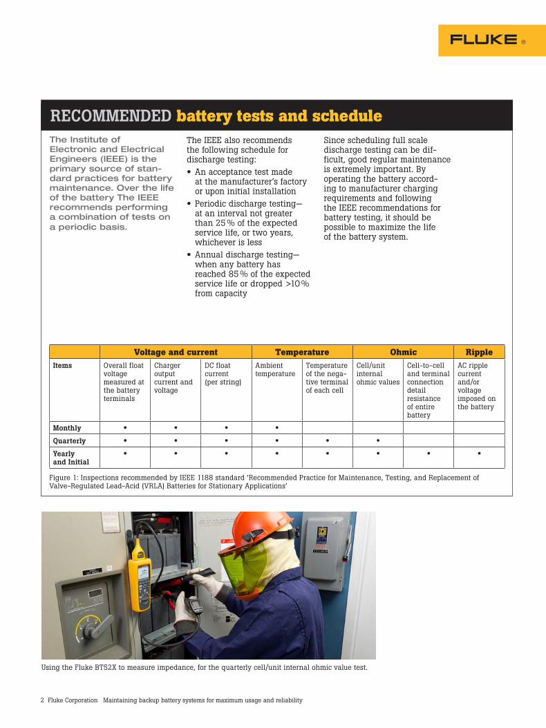
Voltage and current Temperature Ohmic RippleItems Overall float
voltage measured at the battery terminals
Charger output current and voltage
DC float current (per string)
Ambient temperature
Temperature of the nega-tive terminal of each cell
Cell/unit internal ohmic values
Cell-to-cell and terminal connection detail resistance of entire battery
AC ripple current and/or voltage imposed on the battery
Monthly • • • •
Quarterly • • • • • •
Yearly and Initial
• • • • • • • •
Figure 1: Inspections recommended by IEEE 1188 standard ‘Recommended Practice for Maintenance, Testing, and Replacement of Valve-Regulated Lead-Acid (VRLA) Batteries for Stationary Applications’
RECOMMENDED battery tests and scheduleThe Institute of Electronic and Electrical Engineers (IEEE) is the primary source of stan-dard practices for battery maintenance. Over the life of the battery The IEEE recommends performing a combination of tests on a periodic basis.
The IEEE also recommends the following schedule for discharge testing:• An acceptance test made
at the manufacturer’s factory or upon initial installation
• Periodic discharge testing— at an interval not greater than 25 % of the expected service life, or two years, whichever is less
• Annual discharge testing—when any battery has reached 85 % of the expected service life or dropped >10 % from capacity
Since scheduling full scale discharge testing can be dif-ficult, good regular maintenance is extremely important. By operating the battery accord-ing to manufacturer charging requirements and following the IEEE recommendations for battery testing, it should be possible to maximize the life of the battery system.
Using the Fluke BT52X to measure impedance, for the quarterly cell/unit internal ohmic value test.
3 Fluke Corporation Maintaining backup battery systems for maximum usage and reliability
For complete specifications, visit www.Fluke.com
Key indicators of battery failureHealthy batteries should main-tain a capacity above 90 % of the manufacturer’s rating; most manufacturers recommend replacing the battery if it falls below 80 %. When conduct-ing battery tests, look for these indicators of failure:• Drop in capacity of more than
10 % compared to the baseline or previous measurement
• 20 % or more increase in resistance compared to baseline or previous
• Sustained high temperatures, compared to baseline and manufacturer’s specs
• Degradation in plate condition
How to conduct standard battery testsIt is important to make sure you are wearing the proper personal protective equipment (PPE) before conducting the following tests.
Float voltage1. Measure the individual cell
voltage or string using a digital multimeter or battery analyzer such as the Fluke 500 Series Battery Analyzers on a monthly basis.
Charger output1. Measure the charger output
voltage at the charger output terminals using a digital multimeter or battery analyzer such as the Fluke 500 Series Battery Analyzers on a monthly basis.
2. Observe the output current shown on the charger current meter or use an appropriate dc current clampmeter such as an Amprobe LH41A. Measure monthly.
DC float current1. Refer to manufacturers specifi-
cations for approximate values for expected float currents
2. Use an appropriate dc current clampmeter such as an Amprobe LH41A to measure expected float current on a monthly basis.
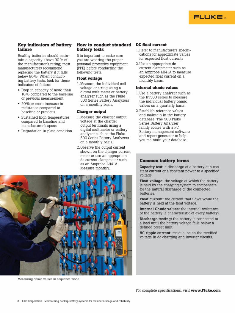
Internal ohmic values1. Use a battery analyzer such as
the BT500 series to measure the individual battery ohmic values on a quarterly basis.
2. Establish reference values and maintain in the battery database. The 500 Fluke Series Battery Analyzer family comes with a PC Battery management software and report generator to help you maintain your database.
Common battery termsCapacity test: a discharge of a battery at a con-stant current or a constant power to a specified voltage.Float voltage: the voltage at which the battery is held by the charging system to compensate for the natural discharge of the connected batteries.Float current: the current that flows while the battery is held at the float voltage.Internal Ohmic values: the internal resistance of the battery (a characteristic of every battery).Discharge testing: the battery is connected to a load until the battery voltage falls below a defined preset limit.AC ripple current: residual ac on the rectified voltage in dc charging and inverter circuits.
Measuring ohmic values in sequence mode
4 Fluke Corporation Maintaining backup battery systems for maximum usage and reliability
Fluke Corporation PO Box 9090, Everett, WA 98206 U.S.A.Fluke Europe B.V. PO Box 1186, 5602 BD Eindhoven, The NetherlandsFor more information call: In the U.S.A. (800) 443-5853 or Fax (425) 446-5116 In Europe/M-East/Africa +31 (0) 40 2675 200 or Fax +31 (0) 40 2675 222 In Canada (800)-36-FLUKE or Fax (905) 890-6866 From other countries +1 (425) 446-5500 or Fax +1 (425) 446-5116 Web access: http://www.fluke.com
©2014 Fluke Corporation. Specifications subject to change without notice. Printed in U.S.A. Pub ID 13269-eng
Modification of this document is not permitted without written permission from Fluke Corporation.
Fluke. Keeping your worldup and running.®
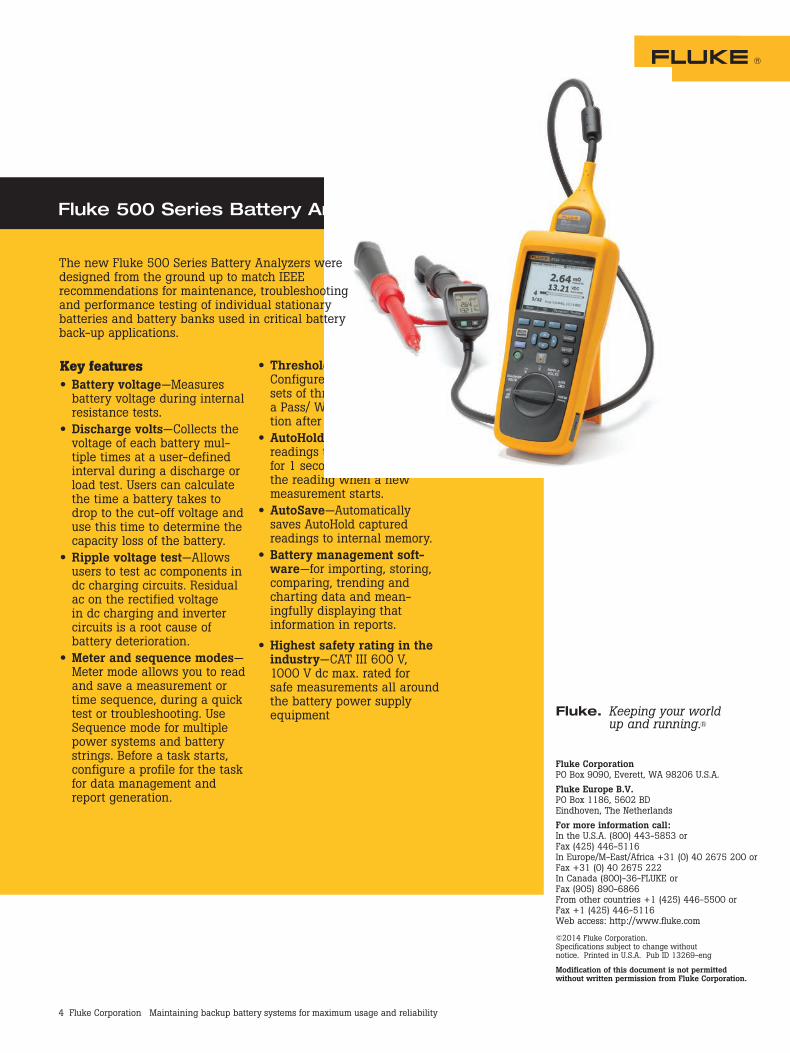
Fluke 500 Series Battery Analyzers
Key features• Battery voltage—Measures
battery voltage during internalresistance tests.
• Discharge volts—Collects thevoltage of each battery mul-tiple times at a user-definedinterval during a discharge orload test. Users can calculatethe time a battery takes todrop to the cut-off voltage anduse this time to determine thecapacity loss of the battery.
• Ripple voltage test—Allowsusers to test ac components indc charging circuits. Residualac on the rectified voltagein dc charging and invertercircuits is a root cause ofbattery deterioration.
• Meter and sequence modes—Meter mode allows you to readand save a measurement ortime sequence, during a quicktest or troubleshooting. UseSequence mode for multiplepower systems and batterystrings. Before a task starts,configure a profile for the taskfor data management andreport generation.
• Threshold and warning—Configure a maximum of 10sets of thresholds and receivea Pass/ Warning/ Fail indica-tion after each measurement.
• AutoHold—AutoHold capturesreadings that remain stablefor 1 second and then releasesthe reading when a newmeasurement starts.
• AutoSave—Automaticallysaves AutoHold capturedreadings to internal memory.
• Battery management soft-ware—for importing, storing,comparing, trending andcharting data and mean-ingfully displaying thatinformation in reports.
• Highest safety rating in theindustry—CAT III 600 V,1000 V dc max. rated forsafe measurements all aroundthe battery power supplyequipment
The new Fluke 500 Series Battery Analyzers were designed from the ground up to match IEEE recommendations for maintenance, troubleshooting and performance testing of individual stationary batteries and battery banks used in critical battery back-up applications.