MAINTAINING AN ALL-DIGITAL PLANT - scte.org · ANALOG VS. DIGITAL Analog Digital Video Audio...
54
MAINTAINING AN ALL-DIGITAL PLANT February 19, 2014
Transcript of MAINTAINING AN ALL-DIGITAL PLANT - scte.org · ANALOG VS. DIGITAL Analog Digital Video Audio...

MAINTAINING AN ALL-DIGITAL PLANT
February 19, 2014

SCTE LIVE LEARNING
• Monthly Professional Development service
• Generally “Hot Topics” or Topics of high interest
to the industry
• Vendor Agnostic – No product promotion
• Free to SCTE members
• Live sessions are recorded
– Members-only benefit

TODAY’S SESSION
• Approximately 50 minutes discussion
• 10 minute Q&A at the end, however..…
– Ask questions anytime throughout the session
– Asking questions adds value and enhances learning opportunity for you and others

HOW TO ASK A QUESTION
• Select the “Q&A” tab
• Type in your question and
submit

NOW LET’S GET STARTED…
MAINTAINING AN
ALL-DIGITAL PLANT
February 19, 2014

CEO & President
VeEX
• Products for Broadband, Metro Ethernet, Transport and CATV Service Providers
• Previously with Sunrise Telecom and DGGN
• M.S. in Electrical Engineering, Certificate on Client/Server computing, M.S. in Telecommunication and General Engineering
Cyrille Morelle

AGENDA
Physical layer metrics used by operators to measure digital network health such as S/N, MER, EVM, BER, CWER, Reverse Ingress, etc.
QAM performance metrics that are used to assess the forward and return paths
Network layer metrics used by operators to measure digital health, such as Latency, Packet Loss, Jitter, etc.
Possible physical and network layer causes of system malfunctions

NOW LET’S GET STARTED…
MAINTAINING AN
ALL-DIGITAL PLANT
February 19, 2014

CATV HFC NETWORK
TV
STB
VoIP
Router
CMTS
Internet
Head End
VoD
Satellite
PSTN
Voice Gateway
DOCSIS
Modem
DHCP serverTOD
serverTFTP server
Data
Return Path / Reverse Path
HDTV, MOD, VoIP, Broadband data services are made possible by Digital Cable Services.
IPTV
O/E
Forward Path

ANALOG VS. DIGITAL
Analog DigitalVideo
Audio
Haystack
Video and two audio channels are modulated to three separated frequencies within a 6MHz bandwidth.They are transmitted at different levels. Normally, a video channel is about 10dB higher than the audio channels.Signals are in analog nature, therefore, more resistance to noise.
Video and audio signals are digitized to digital 0 and 1, QPSK or QAM-16/64/256 modulated, then transmit in a 6MHz band.Digital symbols (bits) are embedded in the Haystack.High digital bit rates can be transmitted in a 6MHz band for up to 40Mbps suitable for internet, VoIP, or HDTV services.Noise can affect the digital bit streams.Uses FEC (forward error correction) to correct errors caused by noise.

DIGITAL SIGNAL MODULATION
Modulation algorithms:QPSK: Quadrature Phase Shift KeyingQAM: Quadrature Amplitude Modulation
QPSK has been used for many years and is the same as QAM-4.
QAM modulates both phase and amplitude with more levels to achieve higher bit rate than QPSK, for example; QAM-16, -64, -128,-256, and -1024
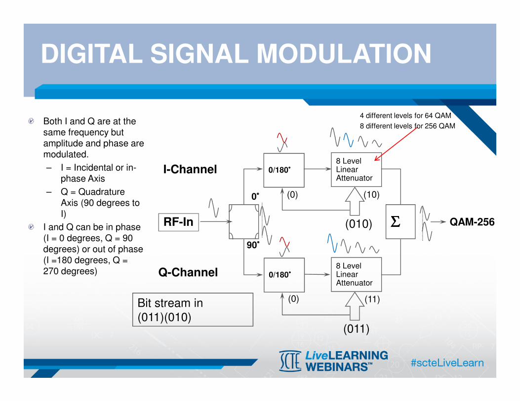
DIGITAL SIGNAL MODULATION
Both I and Q are at the same frequency but amplitude and phase are modulated.
– I = Incidental or in-phase Axis
– Q = Quadrature Axis (90 degrees to I)
I and Q can be in phase (I = 0 degrees, Q = 90 degrees) or out of phase (I =180 degrees, Q = 270 degrees)
QAM-256
8 LevelLinearAttenuator
0/180°°°°
0/180°°°°
ΣΣΣΣ
I-Channel
Q-Channel
RF-In
0°°°°
90°°°°
(010)
(011)
Bit stream in(011)(010)
(0) (10)
(0) (11)
8 LevelLinearAttenuator
4 different levels for 64 QAM
8 different levels for 256 QAM

FORWARD ERROR CORRECTION (FEC)
Adds additional information (data) to the original data stream
The additional information is generated by using Reed Solomon encoder
calculated from the original data stream before transmitting
By using the same Reed Solomon decoder at the receiving end, bit errors can
be detected as are called Pre-FEC errors
By going through the error correction
algorithm, some Pre-FEC errors can
be corrected. When Pre-FEC errors
become significant and some errors
can be not corrected and they are
called Post-FEC errors
Post-FEC errors cause the poor TV
quality or Internet data
retransmission.

THE CLIFF EFFECT – ANALOG VS. DIGITAL
Most visible on digital transmission (Digital Cable TV, Satellite TV, over-the-air terrestrial TV)
Image perfect until saturation
Sudden degradation in quality
* pixelization, frozen frames
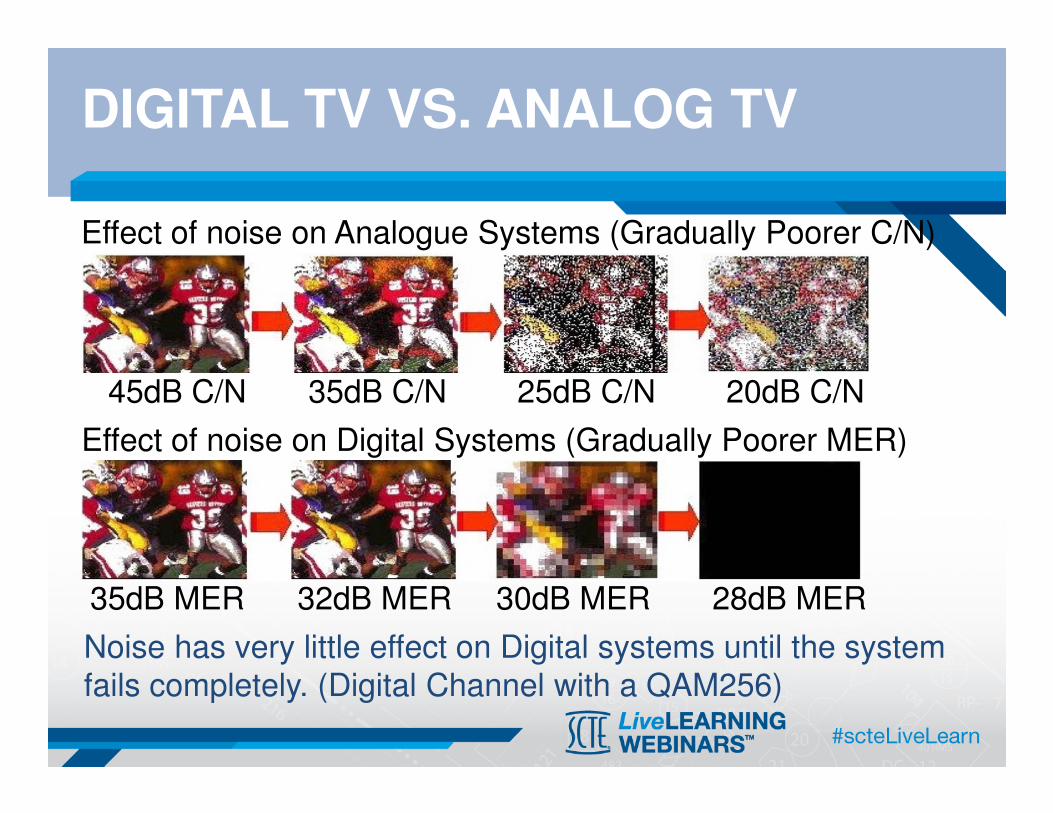
Effect of noise on Analogue Systems (Gradually Poorer C/N)
45dB C/N 35dB C/N 25dB C/N 20dB C/N
Noise has very little effect on Digital systems until the system fails completely. (Digital Channel with a QAM256)
35dB MER 32dB MER 30dB MER 28dB MER
Effect of noise on Digital Systems (Gradually Poorer MER)
DIGITAL TV VS. ANALOG TV

QAM – CONSTELLATION DIAGRAM
Each box in the constellation diagram contains one symbolQAM64: 6 bits per symbol, 64 boxesQAM256: 8 bits per symbol, 256 boxes
Quadrant 1
Quadrant 2Quadrant 3
Quadrant 4

HFC FORWARD PATH
Modulation
type
Std. Symbol Rate (MHz)
Max data rate
(Mbps)
Annex A
(8MHz)
QAM64 6.952 41.4
Annex A
(8MHz)
QAM256 6.952 55.2(440 max 8 Ch bonding)
Annex B
(6MHz)
QAM64 5.057 38
Annex B
(6MHz)
QAM256 5.361 43(320M @ 8 Ch bonding)
(800M @ 20 ch bonding)
QAM 64 or QAM 256 are commonly used

HFC RETURN PATH – DOCSIS
DOCSIS Bandwidth
(MHz)
Modulation
type
Max data rate
(Mbps)
1.0 3.2 QPSK 5.12
1.1 3.2 QPSK
QAM-16
5.12
10.24
2.0 6.4 QAM-16
(QAM-64)
10.24
30.72
3.0 6.4 QAM-16
(QAM-64)
10.24
120 (4 channel bonding)
DOCSIS (Data-Over-Cable Service Interface Specifications)Reverse Path / Upstream Data Rate
Standard symbol rate (bandwidth): 1.28 (1.6), 2.56 (3.2), 5.12 (6.4) MHz

MEASURING ANALOG CHANNELS
1. Video and audio signal levels2. Carrier to Noise3. Adjacent channel and HUM4. More advanced meter measures CSOs and CTB
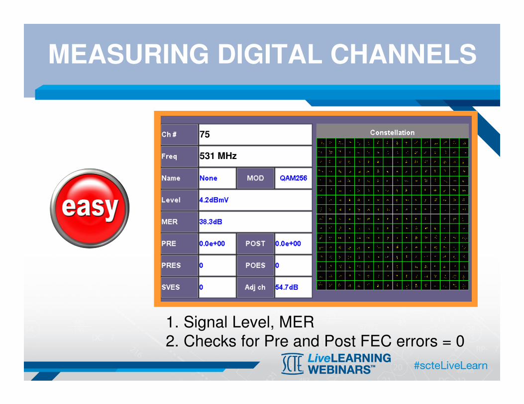
MEASURING DIGITAL CHANNELS
1. Signal Level, MER2. Checks for Pre and Post FEC errors = 0
75
531 MHz
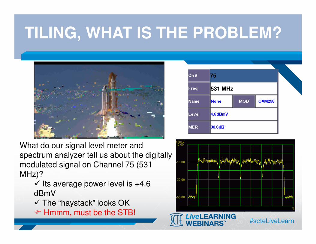
TILING, WHAT IS THE PROBLEM?
What do our signal level meter and spectrum analyzer tell us about the digitally modulated signal on Channel 75 (531 MHz)?
� Its average power level is +4.6 dBmV� The “haystack” looks OK� Hmmm, must be the STB!
75
531 MHz

WHAT’S MISSING?
While a signal level meter and conventional spectrum analyzer
are valuable tools, they don’t tell the whole story about the
health of downstream and upstream digitally modulated signals.
How, then, can one “look inside” the haystack to see what’s
going on?

QAM ANALYZER
QAM Analyzers support a suite of sophisticated measurements:
� Analog channel signal level
� Digital channel average power
� Constellation display
� Modulation error ratio (MER)
� Pre- and post-FEC bit error rate
� Adaptive equalizer graph
Some instruments support other measurements such as ;�in-channel frequency response, group delay�ingress or interference under the carrier�Phase jitter�Max amplitude change�HUM�EVM
Some instruments with DOCSIS cable modem can measure the upstream channels of their;�upstream transmit level�IP Ping, Trace Route�Web browser, Throughput�VoIP, IPTV
More advanced instruments support additional measurements such as;�Symbol rate error�Frequency error�Un-equalized MER�Echo margin�Noise margin�Equalizer stress�ASI MPEG �MPEG analysis

QAM ANALYZER BLOCK DIAGRAM
ASI

DOWNSTREAM PERFORMANCE: QAM ANALYZER
Pre- and post-
FEC BER
MER64-QAM: 27 dB min
256-QAM: 31 dB min
Constellation

DOWNSTREAM PERFORMANCE: PRE/POST-FEC BER
In this example, digital channel power, MER and the constellation are fine, but pre- and post-FEC BER indicate a problem—perhaps sweep transmitter interference, downstream laser clipping, an upconverter problem in the headend, or a loose connection.

MODULATION QUALITY: MODULATION ERROR RATIO
Modulation error = Transmitted symbol – Target symbol
Source: Hewlett-Packard
Modulation error
Transmitted (or received)
symbol
Target symbol
Q
I

MODULATION ERROR RATIO
MER = 10log(average symbol power/average error power)
Average symbolpower
I
Q
Average error power
Source: Hewlett-Packard
I
Q
I
Q
A large “cloud” of symbol points means low MER—this is not good!
A small “cloud” of symbol points means high MER—this is good!
+
+
=
∑
∑
=
=
N
jjj
N
jjj
QI
QIMER
1
22
1
22
10log10
δδ

CONSTELLATION DISPLAY
Poor CNR or low MER I-Q imbalance

CONSTELLATION DISPLAY
Phase Jitter/Noise Coherent Interference

CONSTELLATION DISPLAY
Gain compressionGain compression
Upstream Laser Clipping

CONSTELLATION DISPLAY
Quadrature distortion Zoom function

LINEAR DISTORTIONS
Equalizer graph
In-channelfrequency response
In-channelgroup delay
Un-equalized-equivalentconstellation and MER

LINEAR DISTORTIONS
Micro-reflection at about 2.5 µs (2500 ns):Assume ~1 ns per ft., 2500/2 = 1250 ft(actual is 1.17 ns per ft: (2500/1.17)/2 = 1068 ft)
Frequency response ripple ~400 kHz p-p:Distance to fault = 492 x (.87/.400) = 1070 ft.

LINEAR DISTORTIONS: IN-DEPTH UNDERSTANDINGS
ECHO MARGIN
The Coefficients of the Equalizer will also reveal the presence of an Echo, (a.k.a. micro-reflections). The Equalizer
will cancel such an echo, and in doing so, the equalizer coefficient which corresponds to the delay of the echo will be
much higher than the surrounding ones, “it sticks out of the grass”. The relative amplitude of this coefficient is an
indication of the seriousness of the echo, and its position gives the delay of the echo, hence its roundtrip distance.
The Echo Margin is the smallest difference between any coefficients and a template defined by Cablelabs, as a safety
margin before getting too close to the “cliff effect”. It is normal to notice relatively high coefficients close to the
Reference as this corresponds to the filters in the modulator / demodulator pair and to the shape of QAM signal.
EQUALIZER STRESS
The Equalizer Stress is derived from the Equalizer coefficients and indicate how much the Equalizer has to work to
cancel the Linear distortions, it is a global indicator of Linear distortions. The higher the figure, the less stress.
NOISE MARGIN
We all know that the lower the MER, the larger the probabilities of errors in transmission (Pre-FEC and then Post-
FEC); the MER degrades until errors are so numerous that adequate signal recovery is no more possible (cliff effect).
As Noise is a major contributor to the MER, we define Noise Margin as the amount of noise that can be added to a
signal (in other words, how much we can degrade MER) before get dangerously close to the cliff effect. Noise is
chosen because on the one hand it is always present, and on the other hand it is mathematically tractable. Other
impairments, such as an Interferer, are not easily factored into error probabilities.

LINEAR DISTORTIONS: IN-DEPTH UNDERSTANDINGS
EQUALIZED MER vs. UN-EQUALIZED MER
The MER (Modulation Error Ratio) is the ratio of the QAM signal to Non-Linear distortions of the incoming QAM signal.
The MER should have included the Linear distortions to indicate the health of the signal; but the QAM demodulator
cannot operate properly without the Equalizer and the Equalizer uses the MER as a tool to adaptively cancel the Linear
distortions. Consequently it is convenient to distinguish the MER (non-linear distortions only) from an Un-equalized
MER (non-linear and linear distortions), the Un-equalized MER is calculated from the MER and Equalizer Stress.
The Un-equalized MER is always worst than the MER. A small difference between the two indicates little Linear
distortions, a large difference shows that there are strong Linear distortions. Even if the Linear distortions are
cancelled by the Equalizer, we have to keep in mind that the Equalization is a dynamic process as it tracks Linear
distortions by trial and error even after converging. The larger the Linear distortions the larger the tracking transients
are, hence more probability of transmission error (pre-FEC or Post-FEC BER).
PHASE JITTER
Phase Jitter is caused by instability of the carrier of the QAM signal at the demodulator. This instability could be found
at the QAM modulator and up-converter or in the QAM receiver (Local Oscillators used in frequency conversions). The
phase jitter introduces a rotation of the constellation, where the symbols clusters elongate and get closer to the
symbol’s boundary. Eventually some symbols will cross the boundary and cause an error in transmission. The QAM
demodulator has a Phase lock loop to track phase variations of the carrier; it tracks easily long term drift as well as
some short terms variations (up to 10 or 30 kHz) but it cannot track very fast variations above its loop response. So in
a QAM demodulator, the wideband jitter is more damageable than short term jitter.
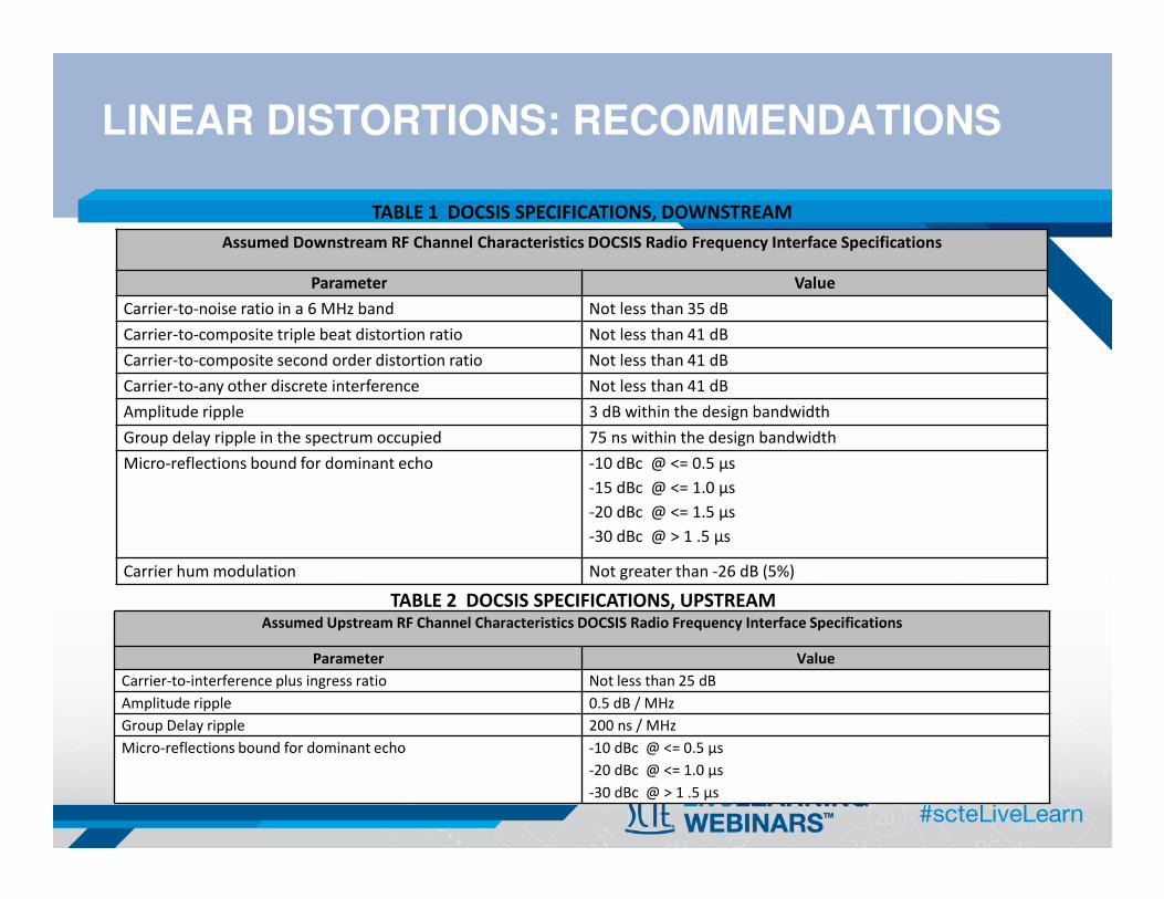
LINEAR DISTORTIONS: RECOMMENDATIONS
Assumed Downstream RF Channel Characteristics DOCSIS Radio Frequency Interface Specifications
Parameter Value
Carrier-to-noise ratio in a 6 MHz band Not less than 35 dB
Carrier-to-composite triple beat distortion ratio Not less than 41 dB
Carrier-to-composite second order distortion ratio Not less than 41 dB
Carrier-to-any other discrete interference Not less than 41 dB
Amplitude ripple 3 dB within the design bandwidth
Group delay ripple in the spectrum occupied 75 ns within the design bandwidth
Micro-reflections bound for dominant echo -10 dBc @ <= 0.5 µs
-15 dBc @ <= 1.0 µs
-20 dBc @ <= 1.5 µs
-30 dBc @ > 1 .5 µs
Carrier hum modulation Not greater than -26 dB (5%)
Assumed Upstream RF Channel Characteristics DOCSIS Radio Frequency Interface Specifications
Parameter Value
Carrier-to-interference plus ingress ratio Not less than 25 dB
Amplitude ripple 0.5 dB / MHz
Group Delay ripple 200 ns / MHz
Micro-reflections bound for dominant echo -10 dBc @ <= 0.5 µs
-20 dBc @ <= 1.0 µs
-30 dBc @ > 1 .5 µs
TABLE 2 DOCSIS SPECIFICATIONS, UPSTREAM
TABLE 1 DOCSIS SPECIFICATIONS, DOWNSTREAM

UPSTREAM PERFORMANCE – CABLE MODEM IP
Proper IP connection and throughput should be verified at the cable modem service location.

MEASUREMENT AND TROUBLESHOOTING SUMMARY
• Constellation display– Low MER or CNR
– Phase noise
– I-Q imbalance
– Coherent interference (ingress, beats)
– Gain compression
– Laser clipping
– Sweep transmitter interference
• Pre- and post-FEC BER– Sweep transmitter interference
– Laser clipping
– Loose connections
– Low MER or CNR
• Equalizer graph– Micro-reflections
• Linear distortionsAdaptive equalizer graph
In-channel frequency response
In-channel group delay
Constellation display (unequalized)
MER (unequalized)
• Transient impairmentsPre- and post-FEC BER
Constellation display zoom function
Upstream packet loss
• Signal level problemsAnalog TV channel signal level
Digital channel power
Upstream transmit level
Constellation display

NETWORK METRICS TO
DIGITAL HEALTH
February 19, 2014

OSI MODEL
7654321
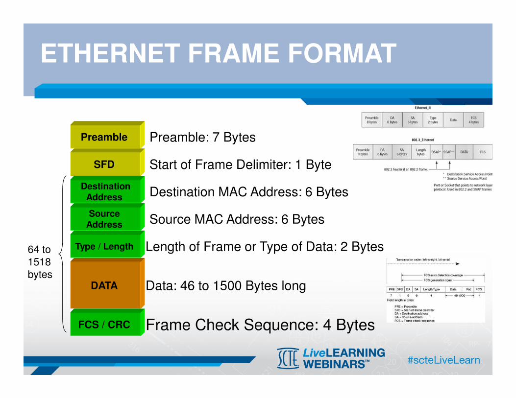
ETHERNET FRAME FORMAT
FCS / CRC
DATA
Type / Length
Source Address
DestinationAddress
SFD
Preamble: 7 Bytes
Start of Frame Delimiter: 1 Byte
Destination MAC Address: 6 Bytes
Source MAC Address: 6 Bytes
Data: 46 to 1500 Bytes long
Frame Check Sequence: 4 Bytes
Length of Frame or Type of Data: 2 Bytes
Preamble
64 to
1518
bytes
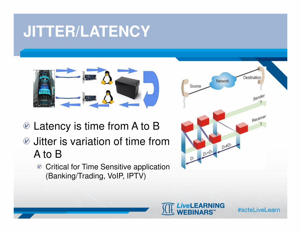
JITTER/LATENCY
Latency is time from A to B
Jitter is variation of time from
A to BCritical for Time Sensitive application (Banking/Trading, VoIP, IPTV)

BERT VS. THROUGHPUT
Ethernet � drops bad packets
Need to know how many frames to be received in order to provide accurate Throughput
Errors in packets = Drop Packets
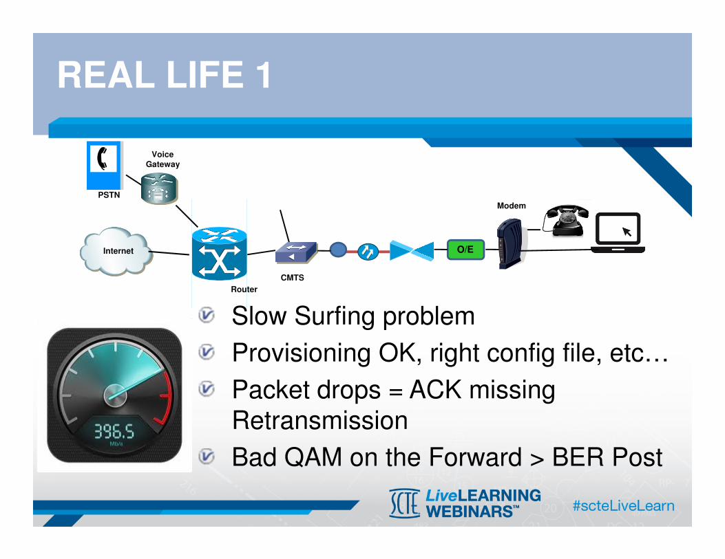
REAL LIFE 1
Slow Surfing problem
Provisioning OK, right config file, etc…
Packet drops = ACK missing
Retransmission
Bad QAM on the Forward > BER Post
Router
CMTS
Internet
PSTN
Voice Gateway
Modem
O/E

REAL LIFE 2
Voice Quality bad (Customer Out)
CQ or LQ?
Customer Out > Return
Look at Noise around Upstream if CQ
Dispatch to IP Softswitch issue if LQ or EMTA
Router
CMTS
Internet
PSTN
Voice Gateway
Modem
O/E

REAL LIFE 3
The PING works or does not work !?!
Does the network support PING?
PING is not sufficient to validate
PING is a continuity check
Router
CMTS
Internet
PSTN
Voice Gateway
Modem
O/E
All Digital means old fashion way = blind
New set of parameters = new visibility and possible prediction
RF vs. Network = they are together
Still a lot of fun
SUMMARY

HOW TO ASK A QUESTION
• Select the “Q&A” tab
• Type in your question and
submit
REMINDER
• This session has been recorded
• Will be available on SCTE’s Member’s Only Site within 2-3 days
• To access previously recorded sessions
login to:
www.scte.org – with your member ID#, then scroll to the bottom of the page and select
““““SCTE Live Learning Archives”””” for a menu of previously recorded Live Learning sessions

LIVELEARNING ARCHIVES
Free for SCTE Members
www.scte.org Under Resources/LiveLearning Archives
Topics include:
• Advanced Advertising
• Broadband Premises
• Business Services
• DOCSIS
• Emergency Alert System (EAS)
• Energy
• Ethernet
• Fiber Transport
• HFC Systems
• Home Networking
• IP
• OCAP
• PacketCable™
• Routing
• Service Management
• Standards
• Video
• VoIP
• Wireless Technology

NEXT MONTH
Register for the next
SCTE Live Learning webinar
Switched IP Video:Cable’s Fast-Track to Infinite HD and IPTV
March 19, 2014
2:00 p.m. Eastern
www.scte.org
Under Professional Development/Live Learning
Available today at the conclusion of this presentation

LIVELEARNING REGISTRATION
Register for the
SCTE LiveLearning Series
www.scte.org
Under Professional Development/
LiveLearning WebinarsAvailable today at the conclusion of this presentation
Third Wednesday of the monthat 2 PM Eastern