MAIN CANAL YAKIMA PROJECT - WASHINGTON by H- G. DEvmY. ... MEMORANDUM TO CHIEF DESIGNING ENGINEER...
37
J HYDRAULICS BRANCH OFFICIAL FILE COPY * * * * * * * * * * * * * * * * * * * * * * * * * * * * * * * UNITED STATES DEPARTMENT OF THE INTERIOR BUREAU OF RX.TION * * * * * * * * * * . · Memor81d1.un to Chief Desiing .+gi+eer * * � * * * * * * * * * * * * * * * * * * . -,'·. , . .. REDESIGN. CHECK DROPS SUNNYSIDE MAIN CANAL YAKI PROJECT - WASHINGTON by H- G. DmY. JR., JUNIOR ENGHI.6ER Denver, Colorado, February 28 , 1939. * * * * * * * * * * * * * * * * * * * * * * * * * * * * * * * * * * * � * * * * * * * * F d r eaources Sanioe ICS .NCH OFF E CO . P
-
Upload
phungtuyen -
Category
Documents
-
view
217 -
download
1
Transcript of MAIN CANAL YAKIMA PROJECT - WASHINGTON by H- G. DEvmY. ... MEMORANDUM TO CHIEF DESIGNING ENGINEER...

J.
HYDRAULICS BRANCH OFFICIAL FILE COPY
* * * * * * * * * * * * * * * * * * * * * * * * * * * * * * *
UNITED STATES DEPARTMENT OF THE INTERIOR
BUREAU OF Ri<XLAlv.:ATION
* * *
* * * * * * * . · Memor8.l1d1.un to Chief Designing .2;11.gi...11.eer * * � * * * * * * * * * * * * * * * * * *
. -.,'·.
, . ... .. REDESIGN. OF CHECK DROPS
SUNNYSIDE MAIN CANAL YAKIMA PROJECT - WASHINGTON
by
H- G. DEvmY. JR., JUNIOR ENGHI.6ER
Denver, Colorado,
February 28 , 1939.
* * * * * * * * * * * * * * * * * *
* * * * * * * * * * * * * * * * * � * * * * * * * *
laleF And Power tleaources Sanioe BYDRATJLICS BP.A.NCH
OFFICE FIE COPY
. ._ BORROnD RETUJilN PROIIP.f£1'

..
..
Denver, Colorado, February 28, 1939.
MEMORANDUM TO CHIEF DESIGNING ENGINEER (H. G . Dewey, Jr.)
Subject: Redesign of check drops - Sum1yside Main cenal - Yakima project, Washington.
1. Introduction.. This report deals with the model studies made on check drop no. 4. In the report of an inspection trip to the Yakima project from May 25 to June 6, 1938 (memorandum to Chief �ngineer, August 8, 1938, by Engineer J. E. Warnock), mention was made of the excessive scour and poor flow conditions existing at rr.ost of the check drops in the Sunnyside Main canal. In that report (page 8), it was stated: 11 The original desig,ned capacity of the canal was much less than that now being carried. As the demand incre2.sed, larger quantities were handled. The resulting increase of velocity scoured the canal to such an extent that a series of 23 or 24 check drops were constructed in the canal. The scour dovmstream from at least 18 of these drops has been a source of continuous trouble since the drops were constructed. The first two were designed for a capacity of 1,076 second .. ·f'eet and, for me.ny ye.a.rs, have been handling 1,300 second-feet. Attempts to stop this scour have been primarily by riprapping, but little or no improvement has been accomplished. At drop no. 2, the width of the canal a short distance dmvnstream from the structure is at least 50 percent greater than the normal width, and Superintendent Moore says that the ho le in the center is about 15 feet deep. The size of the ho le scoured below these structures is excessive considering the very small a.mount of drop. The stream of water through the c ontro 1 is concentrated in the center of' the canal, and the high velocity prevails for several hundred feet downstream with little dis sipation. As the high-velocity water leaves the drop, there is a difference in water level due to the velocity head. This causes an inflow of water on each side near the structure. This inflow is harmful; (1) as it causes a heavy flow upstream to replace that carried away by the high-velocity stream; and (2) as it disrupts all tendency toward the formation of a hydraulic jump. To completely solve this problem, it will be necessary to make a model study of a typical structure. It is believed that the majority of the faults. can be remedi�d by extending the abutment wall sufficiently far downstream so that the adjacent water will not be drawn into the stream, and a hydraulic jump is permitted to form. The int ermediate training walls were included in the Marshall Ford stilling pool for this same purpose. The flow conditions through the structure itself ca.11. be greatly improved by stre�lining the steel brackets which support the flashboards. 11
1

...
On July 16, 1938, the Superintendent of the Yakima project submitted a letter to the Chief Engineer, requesting that a study be made of this problem. In paragraph ( 1) of this letter, it was stated: 11From time to time during the past 15 to 20 years, various members of the organization have made st,ggestions and plans for remodeling; some 20 or more drops or checks of standard design on the Sunnyside canal to prevent or reduce excessive scouring; and erosion in the light volcanic ash soils below these structures. 11 In paragraph (6), it was stated: 11 You will recall, no doubt, that this matter was discussed with you at the time of your visit to the project in March. I have also conferred •Nith iVir. McBirney and Mr. Warnock relative to the problem. It occurs to me that a test on a model of this design would be enli[:,htc:ming in reaching a solution. II . In paragraph (9), it was stated: 11 It is requested that your office make a study of this problem, looking toward a suitable modification of these structures, and furnish designs for our use in connection with a C .c .c. work ;,rogra:m to be Ui.'1.dertaken this fall on at least one drop, such as no. 4, illustrated herew·ith,'1 figure 1 of this report, 11which is typical of the worst conditions • 11
As a result of these recommendations, the problem of the redesign of the check drops was assigned on July 22, 1938, to the hydraulic laboratory of the United States Bureau of Reclamation. · At that time, it vms decided to make model s-cudies on check drop no. 4. The recommended design determined from this study may readily be adapted to the other cLeck drop structures since the drops in the Main canal are of a standard design (figure 2).
2. The Sunnyside Main ca.YJ.al. The Smmyside division of the YakLma project includes about 106,000 acres. Nearly 90,000 acres are now being irrigated. by the Sunnyside Main canal, which has its diversion dan1 and headworks near Parker and terminates about 75 miles to the southeast, near Acton, Washington (figure 3). At the time of its purchase by the Reclamation Service, the canal had a capacity of 650 second-feet at the headworks. After its purchase, plrurn were made to enlarge the canal aild incr0ase its capacity to 1,076 second-feet at the headvv0rks. This work was completed in 1912. From 1917 to 1922, additional improvements were made, allowin6 the capacity at the heacl:works to be increased to 1,300 second-feet, which is maintained at the present time. Due to increasing the capacity of the canal, the r.ydraulic gradient was changed, resulting in increased velocities and lower water surface. To meet this condition, 23 check drops (figure 2) were built in the canal about two miles apart. These structures raised the water surface so that the desired arnount of water could be diverted through the adjoining laterals and, at the same time, reduced the
2

FIGURE 1
l\
A. LOOKING UP8I'RF.AM- DISCHAIDE 1275 SECOND-FEEi'
B. -LQOKIID merREAM
SCOUR AT CHECK DROP 4 - OCTOBER 1938

F I G U R E 2
, 2 ·', 4 " Roiling TOP VIE W AT FRONT
. . 0
· v-.,,,, � ��<i�-"'-"'-"'-"""-""-""-,...._
SEO TION B -11 -�-=-:a..-
Door 1 I
I '.Of carried bock , 1 �==� k, to so/Id earth ' L:..____ _ J ' Gro�nd to be leve le d o f f to
Loca tion of tool house - - ' � h e ight of a b u tment wall ;,:. ot dot ted lin es
HAL F P L A N
:< - 7 '- 0 " ->t< - - - - - B � . Pave to th is line - ·
- _For slope of floshboord groove see details of steel broclr.et
El. 878.80 - ,
NO T E:
1 2 " x 4 " Roiling
Y �
-;-{ Bolts
LI--J-..:.-Y--"-"
r3 "x l0" Plank floor
D E TA IL OF F LOOR
A N D R A I L ING FA S T E N I N G S S C A L E { • 1 '
L • S E C T I O N
I
,- • - A ngles Ts · ·
S E C TIONA L EL E VA T IO N S C A L E {• 1 '
Make lost 8 ' o f pa ving rough with projections above the normal s u r face ( to impede veloc ity )
TA B L E OF D IM E NS IONS A ND Q UA N TI T IES
IIE'IISED1--' -+-2--;,_.3-t--4-+-_5_-+---6
-+-7-+---8-+---'9
-+---'/0'---,,-./-/ -+-'-2-+_1_3-+_1_4=-+----l 5
a....,.-+-I 6"'--+-'-'7-+-_I_B_-+-_1_9_+-...;;2�0:_..+-..;2;;.;..I ___,_=.2.=2--1
:o": b d Q * 0 ::;,/(, A C 8 E F S M N c:c��iE s�f ��F,. =���':s. s::,::rs srm· # ,i:si:os '}'}°�_E.� 8=�!�': E::r,�:s
I 46 8.0 /076 / 0- 6 " 5 0 '-0 " 2 ' -0" / / 0- 6 " l5'-0'' 14 °- 6 " 5°-8\' 0 '- 10 ' 2 '- 3 " 92 .6 4 4 1 4 I 3 4 2 2 80 8 5 3 2 2 8- 2 1 5 6
----+--- - - - -- - - � -- -- · - - ·� 2 45 s . o 1055 2'- 0" 5 o '-6 " 1 ' -6 " 12'- 0" 15'.0" 15'.0 ' 5'-l� o·.s1t 1 '. 9 " 9 7. 7 4 4 1 4 1 0 4 2 2so a o 3 22 B - 3 2 3 9
• -
3 4 5 s . o 10 55 2 ·- 0 · 5 o '-6 " 1 '-6 " 12 ' -0' 15'-0" 15'.0" 5'-l� o·-si. 1 ' . 9 " 9 7. 7 4 4 1 4 1 0 4 2 2 so a o 3 22 B - 4 3 1 0 1-�-+-'---,--t---t=,,---::t------+--,-C--ct-'--,--C-,F'-c---''-±----,---ct--'---c--,,t-'"7"'='7'-7--'---,-----=l---t---+-----+----+-=�---t-- --
4 45 a . o 1055 1 '. 3 " 5 o·-o" 2 '-0" , , ._ , .. 15�0" 14'. 3" 5�7¾' o ·-,o · 2·. 3 " B9 .6 4 4 1 4 , o 4 2 2 ao s 5 3 2 2 a- 5 3 8 6
5 44 s. o 1039 , �1!.-, 5 o'-0" 2 ' - 0" 11'-1� 15'.0" 14'.7'/� S:9 " o ·- 10" 2'.3 " 96 5 4 4 1 • 4 0 7 4 2 2 so B 5 322 a
� :; ::� :��� �::�:: : �::�:: �·.:�:: ,,�::�:. ::��:: ::::�:: :·��:·�::,�:: ��� '�!:: :: : ; :�: : :::� ;:-- �:� :::g �;:-8 4 2 8. 0 982 1 ' . 9 " 5 0'-6 " 1 '- 6 " 1 / '. 9" 15 '-0' ' , 14 '. 9 ' 5'-9 ¾' O'-B !t° l '- 9 " 96 2 4 4 1
r
o , --- 4 �2 2 Bo__ __ B O 3 2 2 B - 9 7 5 5
I-�=-
..:-=!._
9o=.,..
-
=:+
-=4=.,..
2:.,..
��=�
B�=-
-:--=
o=,..
+-:=-=-
9=-=
B=-=
2:-t-
""'=
' ·:_
- o=-=
"'�"
=_
-=
=-=
5=,...
-=
:-;
-�
o= .. ·-=-=
o:"'
":r-:
2= .. ·-=----=
o='"
":r
1 1=7• -=----=
o='" . . �r
,5==c
·=.:·O=
'" . . :i---,4=
...
,·=,--o=
:
c·:r· 5=
=
-·-6=-=
-=';¼;:
;i-
o=:-;
·-=,--
,o�-:
:
'ct:,.'=
-=
2=
-
,-·- 3=-=
-ct; . . =-
-�
a·_-13___2 _
_ + _4 4 ,
_ � o ,
� 4 2 2 so a 5 _
l, 3 2·2 -
1
� BJ a89
, -23 4 I s. o 982 2 '- 0" Z illa h Wo ste woy _ _ •
1--.:..' .:..' -+-4-'o'---l
_s.:..·-=o+.:..9.::..6_6 +--c
, ·,--- o.:...,;i
" _..:.5_+O.,.·-.::..o-::1" t-=
2'-:-·-..:o-::"
1-, ,_· -...:o-::"
t-1 5
':c�:-'o-::"t-1 '4_',..- o
'-:·:t-·
5----:'.6_¾-:':t
' oc.,:,--,o'::--;;1
"1-::2.,..·.3:::---::1
" _B:-8::-2:-----·· 4 4 1 t 3 9 4 l 4 __ � _2_2 ao_ t . 8 5 l 322 - l R - 96 3
12 4 0 8, 0 9 52 t '- 0" 5 0'-0 " 2 '- 0" I I - O" t5'-0" · /4 '-0" 5'.6¼,' 0 '- 1 0 "l 2 '- 3 " B8 2 I <141- , 3 94� , 4 2 2 B0 I 8 5 I 3 22 I 8 - 1 3 I 1 04 9
1-.:..' .:..3_._4_0=-l--"-s_. o
-+_9_3_8+-1.,.·-_o-;;1
" 1---5--+-o...,·-_o-::"+-
2--=· -_o....,"+-1...,t ',--- 0--:":1-
1_5-,-·- o--=·:t-· 1_4-,-'.o_''c+
' ' ...,5'.6,-----;:¾';;to--:.·. ,...,o-;;1
" r::2,·-cc3,--." i----c--1 a=-s::-::2_'_-.,.4"4_1_ -� 4 :_ _ 4 _ _ -2 2a� _ _si+ 3 2_? � B - �4__:_
1
1 , , 2 5
l--'-,4-'--+3::..s:,-1-::-s..;. o:-+
-::9-::'-::5t2.,..·--=6
-;;1
"1---:5
::----r2
7'.-=o
:-;;"
t-o--:··-=O::;";t
,2::.
·-:·
6::.
";t'-:
5.,..�o
::.·;t· , '-=
5.,..'- 6
::;;t"1 6
::.'..o¾=-i" -:o
:---· .
-:4
:.1"
-,d.,..
-2::;
i.;-;;�"
r---' o
=-6�2 +-- 4� +-- 1._9 0_ ;_ _i.._E�� _E;� - - +- 3E? -+- 13__- ,_5 _j 12 2 5
1-..:.'=-5--4.:..3::.6=-
1-
sc.'...:o:-+-=8..:.9..:.2+=
2.,..'·..:.O-;;1"
1--...:5_-r'7' ·-=Oc..
"t-'--:'·-:O::;";t/2::,',--o::-;"
;t'-::5,�0::-;"
;t'-::5,'- o-::·
at· , 5:::;'-A'.»;j="it::o:---· ·-=7
:.l"l
c-:1:---'· 2
::.li.-..'"r· -:9
::-7::-
_ - 4 '1_1_ 3 B 2 _'!.___.. 2_2 BO ( 7 5 , 32 2 ! - B -_1 6 _J I 3 I 3
/6 3 6 s : o 892 2 '- 0 " 5 1 ' -0 " 1 ' - 0" 12 '-0" 15'.0" 15·. 0" 5'-0¾ o ' - 7 " , �2¾' 9 7 4 4 1 3 8 2 4 j 2200 j 7 5 I 3 22 B - 1 7 , 1 364 1-.:.
, =-7
--4-'3=-
4=-i-=-
s:..:. o:.+-==
B-=:4-==o+=, -.-•• -==o
.;1 . . 1--...:
5=--+
o"·.-=o"'"t:2
=-·-:_ o::;".t-:,°'i '--'- o='".l'.1-::5··.o=-·r· , 1
--::4 ----::-t··-o
-::-,t .. , ::-5 :.:6:i
3:ot, _--=o··�:-:::
0:..1 .. -::
2_"· -_""3"'"
+t-, --a a. i ; 4 4 , • 3 1 4 ; ti
11
2 2 ao 1
a 5 t 3 2 2_ _ �= a_- , a = ·). 1 48 8
/ 8 3 2 8, 0 BOB 1 ' . 9 " Snipe s Mountain L a teral i t / 1 6 0 1
1 9 2 6 1 . 1 5 95 o '-s " 5 o'-o " 1 ' - 14" 9�74' 14�0" 12'.1J.7 5·. ,·· o'=l¼" ·1-:-4 �" 7 5 . 3 4 4 1 • 3 1 6 ; .; _ / 2_2 8�+
_! 5 322_ B -20_ ) 1 660
1--2=O--4
...:2::.4-'--f--
1-::-.--'o:-+
--':5:-'-5--=6+-o.,..·---=6
-;;1"
1---5::----ro_·.-=o:c-"
';:;--c, ·.:;;ol�:::i ('.11i: o".!_2�6 " ; 5'.o_� o ·--: 7 " /'.2¾; 7 1 3 4 4 1 3 1 0 4 2 200
I 15 32 2 -;- a - 2 1 1 1 7 9 0 -
2 , 24 6 . 6 5 / 5 I ·. 3 " 4 s . c. VI VI. Heodwor k s )1 0- 5 � 0'-7¼' • S ee s p 6.7 7 l I 56 ..
j B- 24 =-1: 1 96 5
2 2 2 2 6 . 7 4 90 0 � 9 ' 4 O � IJ." 0'-7� 9--��Bi112'. 5� 5�0Jf 0'- 5\Jo'.9¾"t 5B .6 f 3 4 9 • 34 6 : 3 1 1 7 1 0 I 5 6 240 1, B - 2 3 2 1 4 1
1--==-2
==-3
�.:..2::.2=-i-=-5_--=o:-t--=4--=
30:-::--t--=d"-1::ck.
""' 1---4::----to:.
·.--=oc-"t-o· ·- o" a·-i��o" 1 1 ·-1�· 4 '.9 " o '-4 " /o·-2�"j 54 3 349 3 3 2 3 i 1 7 1 o 1 4B 24 0 a - 26 24 20
* To obtain p r e s e n t discharge , mult iply tab u la r value by fm .
D E TA IL O F R E I N F O R C E M E N T A N D B O L T C E N T E R S
SCA L E f" = I '
<;#' '(
; ; - - -�rL · - - - - s --31-::-�-�-�--�-"':. ,r · /3 - 56 - - - -
T I E A N G L E Ts
r_
FRONT V I E W
_ ,r t....,.T----:::-7'----t;:t-----:-7---H___J}:c.:.._ ,_lf_---,----,-----41
/ .1 " - . _ .. T;! i , .1 - •t . .. -- 6 '- 3J ... 3i "' 6 '- Ji ... 3, � 6 '- 81' " - : �. '•'
·� - -- -- - - - - - · - _.J
� 3{.c 1 3 · . s r
T I E A NG L E TR
20 · - o · T I E A N G L E TL
, · ; i
; Jjf � 1 2 3 " 3 " .... - x 1 id L s
t - 4 f ; 3 " , ,f' r
* . 4 { - . . .; GROSS SEC TION OF FACE OF B RACKE TS
AS REOON S TRUO TED IN W I N TER OF 1908 SCA L E 3 " • I ' SEE S. P. 600 FOR DETAILS
3 '. o"
NOTES All plates J" thick. All r ivets ;· diameter, spaced 2· center
to center and I{ from e dge of gussets. All open holes �- diameter e ,cept as noted.
2L s - 2{,2{,{
NOTE Bose angles to be set in
concre te, bearing plate rivets countersunk and chipped between plate and angle.
These a ngles ore not por t of brack e ts.
- ,- Top of p;er - - _ ,j _ - - - - -
ill ' · Bose angle
- - �:3•:. , : .. : r· t , 14 " Machine bolr c�
D E TA IL S OF S T E E L B RAOl< E T SCA L E , .. ,, , .
- - - - - - - - - - - - - - 5 ' _ 3J "
' - -I " Ope n holes
---.•_;11\1 a,
TO P VIE W OF B A S E
N O T E S T l) i s drawing t raced from Dwg. 5 P 628, do ted January 1909. E:le vo t ,ons shown ore for C h e c k Drop 4 only . Fo r deta i l o f m odel see Fig ure 5.
0 £ PA R T M f 'IJ T o,: T "i f 1 _t'·H E R 1 0 R B U R E A U Of R EC L A 'i,A T 1 0 N
Y A K I M A P R OJ E C T - W A S H I N G T O N
MAIN CAN A L S TA N DA R D D R O PS
DRMtH E A "' T llf ACE O C . A, 8 . C H E C K E D . f.. H. E .
SU811 1 T TEO
RECO.,MEHOEO
. . . A P PROVED
3 3 - 0 - 1 7 72

�
�
z CD
� -'"\_,
,R A I N I I IE R
i.
; �\ 1/ // ' z tO
z '<t
�
z � �
i. N
�
��-�:z ,, .,_ ·-�
z 0
�
y
YAKIMA
R. 12 E. I R. 13 E.
U N ITED STATES D EPARTM ENT OF THE I NTERIOR
B U R EA U OF RECLAMATION
YA K I M A PROJ ECT WAS H I N GTO N
A M SM I T H
PRICF 10 CENTS
MAP NO. 2 6 3 7 6
1 9 3 7
OCT. 3 7 1 R. 1 6 E . I R.
_ _/' ·
R. 1 8 E. R. 20 E.
R. 2 1 E.
s I
R. 22 E.
� ,�-/� 'I" /�"I'
�.:,,, / �...,
.0,.;l,i�
t/
j
R. 21 E. R. 22 E.
F I G U R E 3
R. 23 E. R. 24 E. R. 25 E. R. 26 E.
R. SNOQUALMIE
I R
. �-4.,..,._ �,,-� l.£s'v '11"?tn•, -41(£
�
I A_.:s�
0 (J
r=
(I) ST. PAUL
NATIONAL �
'"� ,L. 1/..,i _ ,,(': /r .1\ FOREST �e,i�f�
..i # ' � , \
+,,,� /,/ � , _ -•�'1*.,
,J.# WENATCHEE >-..
� ,:,i NATIONAL \.. � .,,� I
"' r,,'-'"f't� ,p:v FOREST , i.,- � 1/;"f' ,,, i;.,,_v � l_ ;,, .. /,..�-4-,.clt ('- \ �--, £°£ . J 1 · .'""- ·�,,,,..,, 4'J-, z
j ... ' �.� � � · KE ECHELUS
--">•·�,.. i-: /4 . iii ' ... .,,,. � '-......J!.iRESER VOIR KACHE
I
SS \...,_ RESERVOIR_
---Li ---.i,cLE ELUM #/� RESER'vo1R r//////,1/. :;-/?-
1////4 �
j �'////1/, �
% ...... .,/ .. ,,,///.;} \ I� I � GE. z ��, � J<t�<pL� STORA &,� . I rwrna 1
��� ¼"� . . . , "*-o,vER &tston I SYSTEM · · ·/, & .L
· 0 sm� I U>rIU I
R. 28 E. R. 29 E. R. 30 E.
F R A
R. 31 E.
N K L
Eltopia
R. 1 6 E. j R . 1 7 E.
R. 33 E. I R. 34 E.
z '<t
�
N
�
. '/,f/,,.-� I w,,,., �,,,.,,.1,,,,.,'. '111.1.
----<'---
�
s E I N
%·· I r
R. 23 E. I R. 24 E. I R. 2 5 E.
OI
�
i (I) �
f- --+--------t-- ----L I . :;- - - ��- 1 / IYI OL.LG" 11':('ll,-,LO �
R. 26 E.
SCALE OF h41LES
1 0 I 5 10
��e::c=E..I.::E3
R. 27 E. R. 28 E. R. 29 E.

J\
ve locities in the canal. Most of the check drops were built in the winter of 1907 -1908, and the remaining; ones were complete d during the per iod 1909-1916 .
3. Solution by mode l study. Model studies are genera lly adapted to give a so lutio n to a hydr aulic prob lem when the re is no ana lytical method that can be applied vrith re asonab le accur acy. The scour effect of flow throush existing smal l drop structures is a problem o f this type . It is e ntir ely pas -sib le, however, to make an analytical study of the type of flow, for example, hydraulic j ump or standing wave, that exists at the drop struct�res , VVhen this is dono, it is possible to give the reasons for the ir unsatisfactory operation in addition to the reasons give n as a result of observation m ade on the existing structure and on tho mode 1. In order to classify the particular typ e of f low that exists at check drop no . 4, it is first necessary to discuss the hydraulic j urnp and the standi ng wave, refer ring to a sp ecific -energy diag,ram.
4 . The specific-e nergy diagra.c,1 . For a g;iven discharge , a specific-e nergy diagram is obtained by p·lotting , as absc� ssae, specific energy, which is the sum of the ve locicy he ad, ;
g
and the depth of flow, d, and plotting, as or di nates, d, the depth of flow. Figur e 4C shows the specific-energy diagram for check drop no. 4. It has been plotted for a discharge of 1, 264 second-· feet through the rectangular section having a width of 32.13 fe et . It must be understood that the specific energy varies with the depth of flow in a section and is referred to the oottom as a datum which may change from section to section, At one p articu lar depth of flow for the given dischar ge , tlw specific energ;y is a minir,rnm. This depth at which a given discharge flows with a miniLrnrn specific energy is cal led "critical depth. 11 It is now possib le, by referr ing to the specific --energy diagram, to trace the change of spec if'ic energy in the f low with a change of' depth in a sectio n.
5. The hydraulic jump . Referring to figur e s 4B and 4C, it is seen that a hydraulic jwnp is the phenomenon by which rapid f low at a depth, d1, be low· critical depth p asses in an abrupt manner to tranqui 1 flovr at a depth, d2, above critic al depth. The amount of specific -e ner gy head lost in the jump is represented by E1 - E
2• N ow, for a coi1stant cr oss section, the velocity, v1
, above -the j ump has been reduce d to a velocity , v2, below· the j ump.
The depths d 1 and d 2, upstream and downstream from the jump , respectively, are calle d conj ugate depths. A definite re lation between them may be obtaine d by ap p lying the momentum
6

=� I
I :"' ·
z 0 ;: u .. ..
(·do • 7. 10'
T R A N S I T I O N- - .
· · ·E l . 878 . 80
.. I ; j .. . � ,
F I G U R E 4
. - ST A N O I N G WAVES
d., " 7 . 35'· �
. • l <::::- •;·• '/}/ ··1ii,
• ��!;:��:�is ;!:V4r::ii�;; ii ET
P A N E L .
\
�------- - - - ---- 24·-0· - - H H HO - - - - -�HHHHH 14t3• - - - --- -:.f< - H H H • - H U H H H - -20 ·-o· - • • - - - H • • • • - - _ _ _j
A D E PT H R E LA T I O N T H R O U G H D R O P ST R U C T p R E
d z • 7. 30'. -1 - - -- v2 • !5. 38 FEET PER SECON D
B H Y D R A U L I C J U M P
9 r--"T"--.---r----.----,,---,---T--,---,---T--,--"T"---,r--,
8 OEPTH , d1 , OOWNSTAU M FROM JUM P · · -
:_g,,___
1 REGION OF SMALL ENERGY CHANGE
... ( STAN D IN G W A V E ) - · · · · · ··: · · · I t
&
i � , I 0 4 TRANQUIL F L O W . • r . � ---- --- ·! CRITICAL DEPTH dcr,
:; J R A PI D F LOW : I a : I
2
' i . -T R A N S I T I O N B Y M E A N S
. O F J U M P.
\-_ ' ' . · E N E R G Y L O S T I N J U M P
- - - - - >I,
DEPTH, d 1 , UPSfAEA M FROM JUM� � _ . � _ __j_ _ _ _ _ _ . _ _ _ i
0 o,_ _ _.__ ..... 2 __ .. , __ 4,_ _ _.,_. _ _.& __ ,__...,a'--.. e--, .. 0--, ... , --', 2-'---',,---',•
S P E C I F I C E N E R G Y , E • d + r; C
S P E C I F I C E N E R G Y D I A G R A M D I S C H A R G E 1 2 64 S E C O N D - F E E T - W I D T H A T D R O P 3 2 . 1 3 F E E T
O [ P .6 A f .. [ "I T O J" T ... [ l fllll T [ A 1 Q R
B U R E. A U O J A [ C L A .. A T I O N ( A k.. 1 M A P � O J E C T - W A S H I N G T O "I
R E D E S I G N OF CH EC K D R O P S · - S U N N Y S I DE M A I N C A N A L
H Y D RAU LI C M O D E L STU D I ES - 1 : 1 5 S C A LE
H Y D R AU L I C A N A LY S I S A T C H E C K D R O P 4
D A ll 1' N H G 0 • • u,.
T A A C [ O a . I - , a . C H E C JC [ O
s u a 11i11 1 r r t D R E C O llill llill lE N OIE O A P P R O Y [ D
. . . . . . . C O L O A A O D - J A N > , , . .. 33 - D - 1 7 7 3

principle. This relation is
From this relation, if either depth are known for a given discharge , the ing velocity are readily determined. that th.,.s relation app lies only to a
and c orresp onding velocity other depth and correspond
It is important to remember hydraulic jump.
Further study of the specific-energy diagram reveals that, if, in a constant cross section, the depth of flow·, d2 , be less than d1, there will be a gain in spacific energy . But, if the depth of flow, d2, be greater than d 1, there will be a loss in specific energy . In the p articular case where the increase in depth above d1 passes through critical depth, then, as has been seen, a hydraulic j ump occurs with a lar ge loss in energy. It wi 11 also be observed that, in trce case of a hydraulic jump, the ratio, _jJ_ , is much less than unity. This is evident
dz since large er.;.ergy losses are accompar1ied by great changes in depth.
6 . The standing; wave. If sufficient energy is not present in the flow· to cause d1 to be below critical depth, then the flow is said to be in the tranquil state , usually characterized by standing waves or surface undulations and very small energy loss. This phenomenon may also occur even with d1 just slightly below critical depth. Referring to the specific-energy diagram in the region above critical depth, if the depth of flow, d2, is less tha.,.,. d1, there will be a loss in sp ecific energy . But , if the depth o f flow·, d2, be greater t haE d1, there will bo a gain in specific m,.ergy . T hese er,.ergy chaii.ges are directly opposite to those encountered ir.;_ the hydraulic ju.1i1p, and standing waves r.:ia;y form vvith either a...YJ. ir.;.crease or decreasa in c12 • There is no abrupt cl1an 6e of depth when staLding waves exist, so that the ratio .,
�l , is nearly unity. Applying this to the specific-0nergy dia-2
gram in tho re gion above critical depth, it is seen that the rate of change of energy is very small.
7 . Classification o f check drop no . 4 . analytically the type o f flovi.r that exists at check difficult due to the fact that the losses i,1herent
To determine drop no . 4 is in the flow
thro ugh the structure are not readily determined. It is possible, however, to conpute the depth of f low· at the flashboards by applying Bernoulli I s equation fro:.:: the ca:.--:1al section above the drop to
8

the f lashboards . Bernoul li I s equation is referred to a constant datum instead of a var iab le one , as provided in the specific-energy re lation.
From observe d fie ld data ;
Q = 1, 26 4 cubic feet per secon d . D0pth of f low upstream, d0 , = 7.10 feet. Depth of f low downstrean, d3, = 7.35 foet. Flash.boards averar;e two p0r pane l.
Writing, 4A):
Bernoulli ' s e quation from section O to section F ( figure
Vo2
2g-
=
V'lith d0
= 7.10 feet, V 2
0
2g
+ L OO + losses .
= 0.16 .
( The losses are sma l l in this reach and may be neg le cted.)
A lso, VFdF = q, discharge per foot of width . The width is 32. 13 feet a� rectangu lar section.
Now, VFdF = l , 2 6 4 = 39. 33 32 . 13
( 2 )
39. 33 dF
, substituting in ( 1 ) ,
1 24 -05 7. 0 + 0.16 = dF + ---z-- + l . QO .
6 2 6 _ d + 2 4 .05 • - F -:-z- • dp
dF
It is found, by s o lving e quation ( 2), that dF = 5 . 44 feet, or dF = 2. 5 5 feet . Critical depth at section F is obtained from the re lation
d er
l 13 . 2 -· / = ;Cq . /
- -g --
= ri39_.33)::J 113
= 3. 6 4 feet • -3 2. 2 -
( Critice.l depth in the trapezoidal ca..-ia l section i s d ' er = 2 . 81 feet. ) It is noted that one va lue of dp is greater than critical depth, but the other va lue is less than critical depth. It can readi ly be seen that on ly one value applies here. If the tail water be low the drop c ou ld be lo'wered suff icient ly, the
9

depth of flow over the f lashb0ards would be practi cal ly critical dep t h ; furthermore, it would be impos s ible for the flow t o p as s below crit ical depth at this point in its natur al t endency to fall s ince critic al depth corresponds to tho least p ,.J s s ib le content of ene rgy. .Ax1y additional lowering of the wat er sur face at the f lashboards below critico.l depth would raquiro onorgy to be added from a..n. out s ide source. Hence, the value of dF, which i s greater than critical depth , applies here, or dF = 5. 44 feet.
It has been s hown that the following; cri t0ria are neces sary for the formation of a hydrau lic jump : ( 1) The dep th of flow up stream from the jrnnp, d 1, must be below critical depth, a11d the depth of' flow dowtistream from the jump , d 2, must be above critical depth; (2) d 2 must be greater than d 1; and (3) the c onjugat e depths, d 1 and d 2, must bear a definite relat ion to each other. It has also been shown that, when d 1 and d � are aboye crit ic al depth, standing waves will form. The cr i,:;eria neces sary f or -'che formation of a hydraulic jump are not so.tis fied at check drop no . 4 bec aus e : ( 1 ) Considering dF to be s imilar to d1 , tha depth up stream. from a jwDp, it has ueen showt1 that dF is greater than c ritical dept h ; ( 2 ) if, in t he conjug,o.t0 -depth relation, we lot dF = d 1 = 5. 44 f0 0t, t hen dz = 2.28 feet, whic h is not only les s tho..n dF, but it i s o.lso le s s thru1. critical depth, wh ich is impos s ible s ince no onargy ho.s boen o.dded from o.n out s ide source. The criterion neces sary for the existence of stand ing waves is s ati sfied at check drop no. 4 becaus e; ( 1 ) dF i s greater than cr i t ic al dep th; and ( 2) the pre sence of exces s ive tailvrater depth at all times not only resu lts in d2 being above critical depth, but it prevent s the flov, .from approaching criti cal depth at the f lashboards.
8. C ompari s on of los s e s. If the los se s inherent in the flm•r were knovvn from sect ion F to any other points i n the check bas in, it wou ld be pos s ib le to wr it0 Bernoul li I s e quation to determine the depth o.i flow at these points. With this data, the los s of spec ific energy c ould be datermined through the structure . It i s lmO\IVn, hovvever, that the los s of sp ec ific e:ciergy in a standir.g ,vave is about five percent. The los s o f spe c ific energy in a hydraulic jwnp was seen previc:;.sly to be much greater. Assume that , at check drop no. 4, suffic ient energy i s avai lable to form a hydraulic jump. Then, let d 1 = 1. 50 feet, and, ii' the di scharge i s 1, 264 second-feet, v1 = 26. 2 1 feet per second. The c onjugate depth, therefore, w i ll be d2 = 7 . �', O feet with a veloc ity v2 = 5.38 feet p0r sec ond (figure 4B) . l'fo,v-, E1 = 12. 30, and E2 = 7. '76 ; the los s E 1 - E2 = 4. 54 ( figure 4C) . The lo s s il: e:1ergy will be
10

•
1
12 . 30 x 100, or 36.8 percent as compare d to about 5 percent
in a standing wave .
9 . The hydraulic jump compared to standing wave at check d2· op no. 4. In pres ent-day des i gns of s;na l l drop struc -tures, the hydraulic j u..--np is usus. lly adapted to dis s ipate the energy of the f low as it pas ses through the structur e. It has just been shown that, when this is c1one, the energy of the f low· is not only greatly diss ipate d, but the v0 locity of the f low is considerably re duce d.. For bost efficiency, the hydrau lic jump is c onfine d i:::1 a rectangular sti l ling poo l, which usually inc lude s dentated s i lls or teeth to aj. d in the format ion of a uniform ve locity d istr ibution belovv tho j urn.p . If t he canal secti on is r iprappe d. for a short distance downstrearn from the sti lling po o l, vory little scour, :Lf any·, wi ll occur in. t110 canal. But s evere scour wi l l occur downstre run from a d.rop structure, even though a hydrau lic j ump f;;rrns, whe21 the jump is not prop erly cm1fine d. or control le d . 1:.'�any prob lems of this i1ature have been correcte d by mode l studies.
Unfortunate ly the des ign of check drop no . 4, and s imi lar drop str uctures in the Sunnys ide Idain cenal, provi des but little ener gy d is s ipation to the f low. The clas s if ication above showed that standi ng 'Naves form. whi ch diss ip ate only about five percent of the spec-ific energy in the f low. Under th is condition, ·the -ve locity re duction is very little ; hence, the canal downstream is subjecte d to ve locities which are exces s ive for tho fine raaterial, vo lcanic tuff, through which the Main canal f lows . Observations of the prototype w1d mode 1 reveal that the se ve locitie s are concc.mtro.te d near tho c enter of t he cana l. Further obs ervat ions made on the .mod.e 1, discus s e d more fu lly be low·, dis clos e : ( 1) That, as a result of the nonuniform velocity dis tr ibution , large e ddies form a long; the s ides of the canal, which have sufficient ve loc i ty t o cut into the canal banks and produce the exce s s ive scour that exi sts downstream from mo st of the check drop s in the Mairl ca..'1.al ; ( 2 ) that, even though the standing waves at the drop were confine d within a rectangula:c sti lling po o l p ro vided with teeth, there was very· l ittle i:mprov0rnent in the f low; and ( 3) that riprap p lace d along the canal banks be low the dr op struc ture was washe d into the ca.i.----:al .
10. The 1;1ode l. The r.iode l of check dron no . 4 was bui lt to a scale of 1 -S-o-15 ( f igures 5 and 6 ) . T11e drop structure 'Nas constructed of re dw-o od, a.Ld the ste e l brackets were made of li6ht -gage sheet r:,:::tal. The drop s J,;ructure vras installed in a large , metal- line d box, ·which provi de d sufficient length of ap proach upstrean frorn. the drop and sufficient width
1 1

� ..
,-- ---------l
·.., ·.;,
r--- ---- - --- - - - - - - - - - - - -- - - ----- ------ , o· &" - - - - - -- -- - - - -- - - - - - --- - - - - - - - - - - - - - - - - - - - - - -. __ _
: <
I � I : i I i : l ! l ! ! l I I I : I ! i I ! : i i LL 7-
i i
I 1 1 I I I 1 1 I _, __ ,_,_, ! : 1
-� --·-1-
' I I LJ
l'1 ' ! 1 ! 1
-··-· · - ---------·-···· · · - · · · - 6'· 8 " · · · · · · · · · ········ ·- · · · · · · · · ·-ol
! ; i.e.� 1 3.20· ·>+--·· · · ·-· · · 3'· o· . .. . ... . . ...... , 3 . 20" . .,.8.eo"J : : \ : : 1 I
I I I I I
' , · 1 ' ' ' I ' ' ' I O ' ' ' I -L
L> <
: u ' ' ' ' ! i i : · • Ll I' i : -----' '
: , [ , • i
--,--------,-, ' ' ' I ! I
-:!_N
i i j I ! ! : i I ' ' I L_l I
m u
-' ... z z .. ,: ,.,
l f I I II I �
I
f ... .. .. "' -' �
,-- - - - ] l i I E l .��·-'·\.·�t::·_::-- !
I I I I I I I I I
SUPPLY F R O M 8" V E N T U R I
'b -,:.,
.. . . . . . . . . .
"o ...
0 • ' I I I
: � it' · · '. · l"RIPRA� ,...,.,��"""-'liP:""ti,,,-,,�19' V
. . r-::¥?: i �� 2" I 6 "
_ _ _ _ _ _ __ _ __ _ _ _ _ _: _ - - - -- - - - - - ----- - - - - - ----------+--- --' I I
F LOOR · ••
r· 1 . . · 1 . . . . 3 '· 0 "
... ... .. m
#26 G I L I N I N G
S E C T I O N A - A
" ' 1 : : ' '
' ' ' ' ' ' ! _l :
:. . . . . . . . . . . . . . . . . . . . . . . .. . . . . . . . . . . . . . . . . . . . . . . . . . . . . . . . . . . . . 2 1 ·· 4 "
P L A N
1 1 [ 1 1 I
' ' ' ' ' ' L...!....J ' : I .!......!....J
. . - - - - - - - - - - - - - - - - - - - - - - - - - - - - - - - - - - - -- - -- - - - - - - -- - - - - - - - - ...
- - � . .. .. . .. .. . . . . . . . . . . .. . . . . . . . . . . . . . . 7 ' · 6" 9 ' · 1 0 " 1 1 ' · 6 " "':"' - - 1 8 " - - - -�
._ · I 8 11 1 9 . 2 0 " - 1 1 . 4 0 ' - 2 2 . 40 "
[ I 888 . 8 0 SH E N L A R G E D 0 E T A I L
5 '· 6 " - 6 " •
• .. -- �-LJAU,G�T E ·
- -=.--:;=�878
.8� - --. .
..,
• �� ·� • • ·� • .;.. . : .
1� . . . . . . ..... _ _ _ -�---.r, . I l [ I 6 7 , 55 � I
( =-.;..., � ' . - : ;
�n· --· . • ,_ S A N D B E D :1 �;, f':._· ;_,; � �1 .
Cl) · , � '
n' . . l Jr'=� · ' · � r ' · - ··-
r .rr i,:J-:-p· r7 1t r:·: 'rT .. , , S E C T I O N O N C E N T E R L I N E
N · ' ,n
- - - I
0
0
0
..
FIGURE 5
.,. _ _ _ _ _ _ _ _ _ _ _ _ _ 1 4 60" - - - - -------->!
E l . 888.80 ·- . . . L. 5 .6o · ......... � .. . 9.o o · -· -,� ------ ·1� : ; -E l 878.80· . ,
b �
S E E B R A CKET DETAI L· - - - - · . •1',,'J,"• L·�1 SCA L E I N FEET - P RO TOTY P E
0 5 10 15 111, 1 , 1 ,o I I I 0 4 8 �
SCA L E I N I N C H E S - M O D E L
E N L A R G E D D E T A I L O F D R O P
Cl) <O
'·
S C A L E I N F E E T - P R OT O T Y P E 1 5 30 45 60
1 2 24 36 48 S C A L E IN I N C H E S - M O D E L
i .
... ..;
r . . . . 2.4 0' . . . . . ,
• ·
: ..;
"o 1
.. · - ' FLASH BOA R D S 0. 15" 1 0.40" 1 5 . 1 0"
. · ·A L L A N G L E S 0. 1 7 ' , 0 . 1 7" 1 0 .03" E X C E P T A S N O T E D .
BR A C K E T O N l E A C H P I E R
SCA L E I N F E E T - P R O TOTY P E 0 I 2 3 4 5
0 I 2 3 4
� . . . . . . . . . . . . . 4 , 9 0· . . . . . . . . . . . . S CA L E I N I N CH E S - M ODEL
B R A C K E T D E TA I L
7"
60
FOR D E T A I L S OF E X I S T I N G S T R U CTU R E S E E F I G U R E 2
D E P A R T .. £ N T OF' T M [ I N T ( 'I I O A 9 U A [ A U O F' R E C L A M A T • O N
Y A � I M A PRO J E CT - WA S H I N G TO N R E D E S I GN O F C H ECK DROPS - SUN NY S I D E M A I N C A N A L
HYDRAULIC MODE L STU D I ES - 1 : 1 5 SCALE MODEL OF EX ISTI N G STR UCTU R E AT CHECK OROP 4
D R A•N N G D, J III S U B M I T T E D .
T A A C E D . . , A ,I . - , 8 . R I C O IUI E N D E D
C N l C K I D . H G D � � A P P R O V E D
• • • • • • . •••••••• - o,c . 1 1 , , ,n 1 33 - D - 1 774

FIGURE 6
A. LOOKING UPSl'RF.AM
\
B, DROP Br;RUOl'ORE
EXISTING STRUCTURE
and le ngth downstream so that the scouring of the canal would not be restrained. Gages were installed to measure tho depth of flow, whic h w-as c ontrolled upstrear.i by flashboards and dovmstre am by a tail gate . Because the model velocities were considerably less than the prototyp e velocities, it was necessary to use, in the raodel, the finest sand available to reproduce the prototype sc our whic h occurs in the volcanic tuff . A sieve analysis of the model sand is shovm · on figure 7.
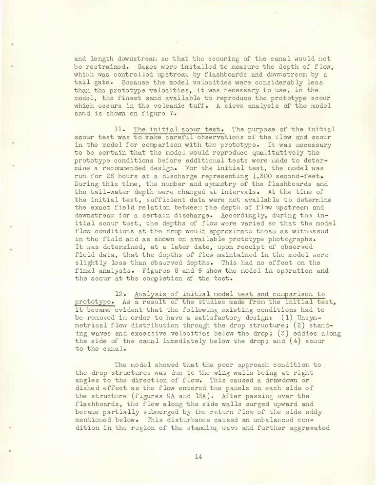
ll. The initj_al scour test . The purpose of the initial scour test was to make c areful observations o f the ilow and scour in the model for c or.ip arison with the prototyp e. It was necessary to be certain that the model ·wou ld reproduc e qua.li tati vely the prototype conditions before additional te sts were r;1ade to determine a rec o:rrnn.ended design . F or -che initial test, the model was run for 26 hours at a discharge representing 1, 300 second-feet. During this time, the nur,tber and symr,1etry of the flashbo ards and the tai l-water depth vvere changed at intervals . At the time of the initial test, sufficient data were not available to determine the exact field relation between the depth of f low upstream and dovv11.stream for a certain discharge. Ac c ordingly, during the initial scour tost, the depths of flow ·,rnre varied so that the model flovv c onditions at tho drop wou ld approxinate those as witnessed in the field and as shown on available prototype photographs. It was determined, at a later date, upon receipt of observed field data, that tho depths of flow· maintained in the mode 1 -,,ere slightly less than obsorved depths . This had no effect on the final analysis. Figures 8 and 9 show the model in operation and the scour at the completion of the test.
12. Analysis o f initial raodel test and c cr.iparison to prototype. As a result of the studie s made fror.i the initial test, it be ca.rne evident that the following existing conditions had to be rer.,.oved in order to have a sat isfactory desit,-i1. : ( 1) Unsymmetrical flow distribution thr ough the drop structur e ; ( 2) standing waves and excessive velocities below the drop; ( 3) eddies along the side of the canal irnr.1ediate ly below the drop; and ( 4) scour to the canal.
The r:wdel shmNed that the poor approach c ondition to the dr op struc tures was due to the ,,ving walls being at right angles to the direction of flow. This caused a drawdovm or dishe d effect as the flo-,v entered the panels on each side o f the structur e (figur es 9A and 18A ) . After passing over the flashboards, the flow along the side walls sur ged upw·ard and be c ame partially submerged by the r eturn flow of the side eddy mentioned below. This disturbance caused an unbalanced c ondition in the r e gion of the standin6 wave and further aggravated
14

a:, ll'l 0 0
1 00 � .... '\. -
'\.
90 .... ----"\ ,
\ \ ,___
80 \ \ \ \ \
70 \ \
S I Z E O F O P E N ING I N I N C H E S
tO '" - , . ..D - "" 4" 0 u 0
- - - - - - -·- i- - ---- - -- -
''°' en 0
Ill LO a:> r-- � ---
-- -- -- - - -- · -- · •---- ------- --·+-- ·· --··-I I
· - ---- -t-- - -- -----�--·+-· - - - ---- �--
--- -- ----- --+ ·-
\
Q W 6Q z _ < . t---� so
w U lt() a: "' Q. .
30
20
10
0 Pan • 100
v . ,.. _ 1 /Lt'U.
\ \ \ \ \ \ \ \
\ \ '
\ \
·-
' .
\ \ \ \ \ \ \ \ '
\ \ \ \
· �a •2a
.
---.-, "' . . • 8 • Jt i
''
S IEVE SIZ E
•
0 0 0 0 LO Ill 0 0 t-: -= (Tl cl:i
0 .___ --
1 0
20
--
30
Ito � CJ) en -(
so A.
"" 60 :5
0.
70
80
90
--100
¼" ,� II
I l 3 " 6"
.
GRAD I NG
S i eve o/o Cum . Com b . ¼ S i u Ret. o/o R at. Cum .
6 ''
3 ' " . ·-l ½.-3Ja." 3/e "
• I+ 0 . 0 0 . 0 -F ·M * 8 0 . I
- ·------0 . I ·--
• l lt 0 . 4 0 . 5 •'28 4 . 7 5 . 2 • 48 4 2 . 6 4 7 . 8
• 1 00 3 9 . 7 87. 5 Pan 1 2 . 5 1 00 . 0 F. M . 1 . 4 1 Com b . F. M . G/s
-
Remarks . . . . �L�.v�_ Q_f'.l.9. ! Y. �. L� . . 9f . . . . . . . !?. gn .o. _ _ V.$.�_Q_ . .i.r:i_ . 1 _ _ :_ ! .�. _ �-c.oJ� . . . _ m o d e l _ o f _c he c k _ _ d ro p 4. _ _ _ _ _
' - - - - - - - - - - - - - - - - - - - - - · - - - - - - - - - - - - - - - - - - - - · - - - --- - - -- - - - - - -- - - - - --- - - - - - ... - - - - -- - - - - - - - - - - - - - - - - - - -- - - - - -- - - - -- - - - - - - - - - - - -- - - - - - - - - - - - - - - - - - - - - - - -- - . - - - - - - - - - - - - - - - - - - - - - - - - - - - . - - - - - - - . - - - -- -
D£PARTMENT OF THE INTER I O R BUREAU O P' RECLAMATION
PROJ ECT . . . '!' AK_ ! ff!_� -� .\¥ A _S_ �- I _� � � (?_�- -f"EAT U RE - -�- e:.D.�$ 1J� .N. . _Q_f_ P ! I; Q � . p R_9 P S AG6REGATE . . . . . . . . . . . . . . . . . . . - . SAM P L E .. . . . · · · · · · - · - . . . . _ _ _ . . . . . . . . . . . . . . . DIV.WM _t:f_-�.,Q. _ . . . . CHfCKID . . . . . .. . . . • . .
Date . _, · 9 _-_.;i �- - · · f J..t e>E_N vfi i;:,_coi,o�AtJo! 3 3 P O ·- 1 775,
I
.,, G)

A. SCOUR APTER 21 HOURS .,. DISCHARGE 1300 . SECdND-FEEr UPSrREAM WATER SURFACE ELEVATION 886 ; 25 ·
DOWNSI'REAM WATER SURFACE ELEVATION 884.55 · · ;FOUR FIASHBOABDS PER B\NEt
. _ · . . B; · SCOUR AFTER 26 HOURS MODEL ELEVATION 'lOO . O EQ.UAIB PROI'OI'YEE ELEVATION 8'77 . 55
EXT ffi'Tl\Tn. i::rrmTr.'T'TTRW.
FIGURE 8

A. SCOUR AFrER. 21 HOURS - DISCHARGE 1300 SECOND-FEET Ul'SI'REAM WATER SURFACE ELEVATION 886 . 25 ,
DOWNSI'REAM WATER SURFACE ELEVATION 884. 55 FOUR . FIASIIBOARDS PER PANEL
B . SCOUR A:FrER 26 HO"LRS MODEL ELEVATION. 100 . o EQ.UALS PROTOTYPE ELEVATION 877 . 55
EXISTING STRUCTURE
FIGURE 9

the poor flow distribution extencling downstream ( figur e 8A) · The flov,r throu6h the other panels was syrm;-ietrical, but it had a tendency to pi le up on the up streren face of the stee 1 brackets a..Yld remain split as it plunged into the check bash1. This disturbance did not prevail after the flow had reached the region of the standing wave (figure 8A ) .
The standing wave, as discussed on page 8 , formed over the check basin (figures 8A and 9A), and additional waves, accompanied by excessive velocities, extended downstream about 150 feet . The higher velocity flow was concentrated near the center of the canal, but, on each side of the canal, starting at a point about 75 feet below tlie drop, the direction of flow was upstrea,,1. This peculiar co"nbination of flow downstream at the center of the canal and upstre am along the l�- to 1 side slopes formed a large eddy along each side of the canal (figure 8A ) . The upstream cor.,ponent of these eddies had sufficicmt velocity to cut into the canal ba.nks and produc0 excessive scour .
The scour in the mode 1 appears to be more severe than in the prototype, as shown on figures 1, 10 , and 11. This was expected since the sand in the iaode 1 was :nore saturated and less co:r:i.pacted than the material in the field. The scour to the riprapped cru.1al bottom. for a distance of 20 feet downstream fro:r.1 the drop was not excessive, but , beyond this point , the canal bot-tom. was he avily scoured . Observations on the model revealed that , as the flow passed over the flashboards, it was partially def le ctod upwards by the weir wall at the lovrnr end of the check basin. This had a tendency to reduce the a1i1ount of scour j ust b0low the drop. But, as the flow passe d downstream to the end of th e riprapped transition, high velocities prevailed along the bottom o f tho canal, which scoured a. largo h ole ( figure 9B) into which the rip rap near this region was d0posi tod. This may exp lain the reason why the riprap at the pro totype structure is continually washed into the pool below· the drop .
It will be noted that the scour pattern in the Ii,odel (figure 8) is symmetrical about the cent er line of the canal whereas the scour at t11e prototype (figure 1) is on the left side of the canal. This difference in scour pattern is due principally to the fact that there v,as no curvature in the canal alinemeHt in the model above or below the drop structure whereas the canal curves to t he left upsire aw. fron the prototype drop structure and to the r ight downstreai:i. Another factor contributing to the prototype scour pattern has been the r,1ethod of p lacing the f lashboards. These have been p laced unsyrat.1etrically so as to divert tho flow frori1 the scoured section of the canal. The model showed definitely, hov-rnver, that scour ·-rfill be excessive below
18

A TO P O G R A P H Y I N P O O L B E LO W D R O P F R O M F I E L D S U R V EY
AT E X I S T I N G S T R U CT U R E C H E C K D R O P 4
0
B T O P O G R A P H Y I N POOL BELOW DROP F R O M T E ST
OF 1 : 1 5 S C A LE M O D E L OF EX I ST I N G STR U CTU R E C H ECK DROP 4
+50>+-------- 50•+-------- 5o-+-------
.>··- CANAL BEFORE TEST
FOR DETAILS OF RECOMMENDED D E S I G N SEE F I G U R E 13
0 g - so,+--------50Hi1---------50'"'f--------so
01 "•AT M I NT 0, TNI I IIT( R I O• 8UAIAU OP' AICLAN AT t ON
YA K I M A PROJ ECT - WASH I N GTON
FIGURE 10
TO P O G R A P H Y I N POOL B E LOW DROP FROM TEST OF 1 : 1 5 SC A L E M O D E L OF R ECO M M E N D E D R E DE S I G N
O F E X I ST I N G S T R U C T U RE CH E C K D R O P 4 R EDESIGN DF CHECK DROPS - SUNNYSIDE MAIN CANAL HYDRAULIC MODEL STUDIES - 1 : 15 SCALE COM PARISON OF SCOUR AT EXISTIN8 STRUCTURE
WITH SCOUR IN MODEL
o•••• . . . . . . '!·. 0 o._... 1ua•1n10 . . ,ucu . . �:�- - ,.._ . . . . . ucoa•a.oco. CNIC .. O � - �; �:."� • . . . Af"f'IIOYID . •
ouvu , COLOHOCI - 010. •, 1•sa 33-- D- 1776

.f
A. SCOUR AFTER 21 HOURS - DISCHARGE 1300 SECOND-FEET UPSI'REAM WATER SURFACE ELEVATION 886 . 25
DOWNSTREAM WATER SURFACE ELEVATION 884 . 55 FOUR FIASHBOARDS PER PANEL
B . SCOUR AFTER 26 HOURS MODEL ELEVATION 100 , 0 EQUALS PROTOTYPE ELEVATION 87 7 . 55
EXI SrING STRUCTURE
FIGURE 1 1

the drop re gardless of the a.linornont in tho canal, the comp actness of the material, or th0 S;yi.!U,1etry of the flashboards.
13. iviodel tests leading to the recorn�iended design. Before a satisfactory solution to this problem could be obtained, it was necessary to investigate r;:any designs in the �aodel and us� the best features of' each. }�ach design investigated was tested with various discharges, tail-water depths, and flashboard arrangements. Careful study was made on the perfor:,1a.nce of each desig;:1 esp ecially at maxir.:Ut--:1 discharge since, at that discharge, the r,:ost unfavorable conditions existed. Before studies could be r.1-ade on the e lir;iination of the standing waves and excessive velocities, it -Nas necessary to nake the flow syran,etrical at the approach and below the check basin. To iriiprove the flow at the approach, the steel brackets were streamlined (figure 12J), and curved trainin g walls were added to the wing walls ( figure 12B). The flow was improved to such an extent that curved trainin g walls were adapted to succeeding designs since they e lininated the drawdown or di shed effect in the flmv at each side pane 1. Although the strear;1lining to the brackets ir,,proved the flow·, it was found later that the streamlining vrnuld not be required. To inprove the flow below the check basin, a rectangular stilling p ool was formed by extendh1p, the vertical side walls dowr,.strea.Ll ( figur e 12B) . This prevented the return flow of the sicie eddies fror.1 subr.1erging the nain stream as it left the check basin.
With the symmetry of the flow greatly improved through tha drop structure, it Yvas possible to r;i.alrn a careful study of the flow t o determine the p rocedure necessary for the elimination of standing waves and excessive velo cities. Observations revealed that, as tho jet p J.ung;ed over the flashboarcls into the check basin, it did not closely i·ollow along the stilling-pool floor but was deflected upwards by the we :i.r wall at the downstream end of the check basin. This condition caused nost of the higher v,0locity flow to be concentrated near the surface, which r,iade it not only difficult to elininate the standing waves but nade teeth in the stilling pool (figure 12B) ineffective in dispersing the high velocity. If the jet could be na.de to follow the stilling -�pool floor, it would be possible to greatly reduce the tendency for standing waves to forn, and teeth would have sorae effect on the velocities. To acconplish this, the design shown on figure 12C was tried. In this design , a sloping apron was placed between each pier fror.1 the top of the upstrean weir wall to the top of the downstre am weir wall of the check basin. As a result , the entering jet had a tendency to follow the stilling-pool floor. This tendency v.ras slightly increased v,hen slide gates were used at th<a stee 1 brac}mts instead of f lashboa.rds ( figur e 12C) . With slide gates in place, the direction o.nd the velocity of the jet
21

\
r------- - - - - - · · , s· - 3 " - - - - - -- - - - -·I EL. 888.80 · . �·· - 7 '· 0" · · ·:·· · · ·· · I I c 3 • ····· ·--i
r-------� 1 \ : : R I PRAPPEO T R A N S I T I O N · ..
El . 878.80· · ·
CU RVED T RA I N I N G WALLS PLA C E D AT W I N G WALLS .,
�- - - - - - - -- - - - - - - - - - - - - - - 3 3 '
- 9 " - - - - - - - -- - - - - - - - - - - - - - - � : ! : R E C T A N G U L A R P O O L A D D E O· . E l 8 8 8 8 0 !
-V A R I E D · · ·
EL 877. 55 · · · .
,�z:2:::::::2::z:::·P1:; ___ J : l FOR C O M P L E T E D E T A I L S OF E X I ST I N G STR U C T U R E S E E F I G U R E 2 T E E T H 4 0 ¼ A N D
SPAC E S 60% A C R O S S PO O L . I I I I
1 511- - � �----- 1 2 ·- o·------ -..l r 1 2 "
i · · · · · · V A R I E D
1 4 '· 3 " . . . . .. . . ,l.. . . . . -. . . . . . . . 1 9 '· 6 ''. . .. .. . _ ... .
CURVED TRAI N I NG WALLS PLACED AT W ING WALLS ·,,
P O O L F L O O R P L A C E D AT VARIOUS ELEVAT I ONS O N 2 . 5 6 : I S L O P E".
' ' ' ' ' ' �---- - - -- 1 4 !. 3• - - - ------�
A E X I S T I N G S T R U C T U R E
r<-·---·-----------·------ - ---- - -------------� 33 '· 9"
E l . 8 8 8.80 · · · . I
TEETH 1 5" W I D E PER PA N E L .
· --l.··· ·VA R I E D··· . . • .--·
' E l . 875 .5 5· · . · ·J . ·"Q: � .. . . o -·. - .
I I I I ' ' .i-···'- VA R I E D · · · ··-·.., I ' ' ' ' ' ' � -- ----- 141
• 3" ---- ___ ...:,.. _________ _ ' ' ' 1 9 · 6 ··--·---··----l
E S L O P I N G A P R O N
C U R V E D T R A I N I N G W A LLS P LA C E D AT W ING W A L L S . · .
B S I D E W A L L S E X T E N D E D
r·· · · · · --·· · · · ·· · · · · - · · - · · · · - - 4 2 . • 0 .. . • · · · · · · · ··· ····· ·····- · · ······-···l -----�- \, :
'i---,1------------------'E:.:.I :.:.. 8:.:8:.:8:.:..8:.:0-:_· ·_· :e.· -<'
/ E l . 874 . 5 5 · · . .
RA D I U S OF B U C K E T A N D PO S I T I O N O F B U C K ET O N I : I S LOPE VA R I E D .
I I
.__�-"'- .. _;;,.·: · ·,E l . 8 68 . 8 0 I
'--�-�-'-'---'�--'---------------- - - J
F B U C K E T
*· · · · · · · · · · ···- ....... · - · · ······· • 4 2 • • o ' - - - - - - - ----------- -- - --------- - -....... C U R V E D T R A I N I N G WALLS
P LA C E D AT W ING W A L L S : · . • ._ ' '
' '
,--------''--�.._.
,'---#-----------------=-E-'1 .-'8-'8-'-8-'. 8-'0_· ·_.,.____,
PA R A B OLA VARI E D A N D E L E V A T I O N OF P O O L FLOOR VA R I E D .
H
1 · .. - · · VAR IED· . . :
El 86 8 8 0· · ·1
CURV E D T R A I N I NG WA LLS P L A C E D A T WING W A LLS . · .
D I M E N S I O N S '"A" TO "H " I N C L . VA R I E D , S E E F I G U R E 1 3 FOR R E CO M M E N D E D D E S I G N .
CURVED TRA I N l1N G WALLS Pi.ACED AT Wl �G WALLS
1 : 1
! ' t 1 ......
A P R O N PL A C E D B E T W E E N Pl t R S ·
I :
CU R V E D TR A I N I N G W A L L S P LA C E D A T W I N G W A LLS · .
· · · · · · · ·· · · · · · · · · · · · · · · · 3 3 ' · g " · · · ·-·· ·- - ·· · --· --·····11
S L I D E G A T E E A C H PA N E L
E l . 8 8 8 . 8 0 · ·
VA R I E D · . r·--8 77. 55· · · · ·1
r· ······ · VA R I E D
' ' '
�--- - - - - - - - 1 4 '- 3 " _ _ _ _ _ _ _ _ l. ____________ 1 9'.. 6 " _____________ J
C S L O P I N G A P R O N
:<· ····· ·-··· · · · · · · · · · · · · · ·· · · · · · · · · · · · · 4 2 '· o "
, · · D E F L E CT O R
-
E l . 888. 8 0· · ·
->-
R A D I U S O F B U C K E T A N D P O S I T I O N
CURVED TR A I N I N G WALLS PLACE D AT W I NG WALLS ·,
· , .
�----�---
C R E S T R A I S E D. A P R O N P L A C E D BETW E E N PI E R S . · · ·
S E C. B - B
OF BUCKET ON 1 : 1 S LO P E VA R I E D . "'-...:..'"'--'C.....;...'---'"-'-�•�·CL _____________ _j
G D E F L E C T O R A N D B U C K E T
. • • • • • • • • • • • • • . • • • · · · ·· . . . .. . . .• · · ·· - . H --- - - - - - - - - - - - - -- -- - - - - - - - - - - --------.w '
· · · · · · A · · · · · · ·--:
'1--�-�-+,-...,...C---�-------------
. . . ... t "o
. . . . . . ! -�·--- ·
' ' ' , r· - - - - - - - -- - - - - - - -- ---- 0 - - - ----- - -- - - - - -�
• �- - - - - - - - - 1 4 '- 3 " - - - - - - - -�- - - - - - - - - - ----- - -- - - - - - E - - - - - - - - - -- - ----------..,,.l
I
---- -----[
O G E E C R E S T D E F L E C T O R U S E D W I T H S M A L L R E V I S I O N TO E X I ST I N G S TR U C T U R E .
F I G U R E 1 2
/ /
/�
r ····--··----·----------· 3 3 •. 9 . -- -------------------.,
' '
' ' '
E l 8 8 8 . 8 0· · ··
-
' : / r··----- ,VA R I E D ! �---- -- - 14'- 3" -- -----�---------- 1 9 '.. 6. __________ _J
D S L O P I N G A P R O N
P l E R
A - A
J S TR E A M L I N I N G O N B R A C K E T S
SCA L E I N F E E T - P ROTOTY P E 0 5 1 0 15 20 25 I 1, 1 , 1 ,1 I I I I I I I I I I I o 4 e � � w
S CA L E I N I N C H E S - M OD E L
D E PAR T M E N T O F T H E I N T E R I O R B U R E A U O F R E CL A M A T I O N
Y A K I M A P R O J ECT - W A S H I N GTON R E D ES I G N OF C H ECK D R OPS - S U N NYSIDE MAI N CANAL
HYDRAULI C MODEL STU D I ES - 1 : 1 5 SCALE DESIGNS I N VESTI GAT E D I N M O D E L OF
E X I S T I N G S T R U C T U R E C H E C K D R O P 4
'DRA W N . . N. G. D. J A . . . . . . SU B M I T T E D .
TR A C E D . . ': �: � : :"'°. r-. flli: . . . • R EC O lf ll END£D • •
C H E CK E D . . . ':f! !J: .�- -�!': . . A PPROV E D . . . • • •
D E NY E R , COLOROD O - D EC. , •• ,... 33 - D - 1777

were more nearly parallel to the apron bet-ween the piers. The teeth in the stilling pool were r,ow more effective , and it was noted that the veloc ities below the drop were slightly less . For sm all dischaq;es , the standing waves were partially eliminated, but, for max:i.mu.."11. discharge , it was necessary to raise the slide gates to such an extent that the j et no longer followed the apron into the stilling pool. As a resu lt, the standing wa-v-es still forrne d. This design , however, ·was improved by providing more depth of sti lling p ool and increasing, tho slop e of the apron ( figures 12D and 12E) . With these improvmacmts, the tendency of th 0 j et to follow· the apron into the stilling pool was further inGrease d. This rendere d the teeth still more effective , and the velocities were further decreased, especially with thG added depth of pool . The standing waves still persisted, however, as in the other designs .
·when it was seen that the ve locities below the drop decreased with an increase in p o ol depth and the tendency for the j et to follow a steeper apron viras nore favorable, the design shovm on f igure 12F was investigate d. This provided still greater p o ol depth but added a bucket . The buckot has, in certain instances, boen successfully used to dis sipato e11ergy by creating a large roller in the floil. If prop0r tail-vrater depth is fur nished, the buckot may pro duce good r0 sults; otherwise, the roller will cause excessive boil or be drovmed . It was hoped that the j et would follow the 1 t o 1 slope into the buc�.::et and result in the forraation of a ro Lh, r instead of the standing wave . This was not realiz ed, however, because, when normal tai 1-water depth was maintai ned, ·which was necessary to pr even-:; excessive boil, the j et failed to follow tho slope into the bucket sufficiently to el:i.r.1inate the standing waves . The velocitios below the pool were still excessive . This design was irnproved in one resp ect by placing a def lector at the steel brackets ( figure 12G ) . The def lector forced the j et to follow the slope into the bucket so that the stanc:i.ing wave was complete ly eliL1inated; how0ver , tho velocity o f th.J entering j ot was increase d as it passed under the deflector, and t his caused oxcossivo boil in the pool in addition to excessive scour and veloc ities downstre am frrn;"i the p ool. Although tb3 use of a bucket did not vvarrant further study, additional study was made in an attempt to r::aL:c the j ot follow a slope into a stilling p o ol without using a doflector. The de sign show.a. on fiEur o 12H p rovided an o goe crest, which ,aore nearly f it the traj ectory of the entering jet . The j et followed the ogee crest surprisingly well at raa.,"'\. imum diseharge and f or all ranges of tai l-water depth. But, if flashboards were added, the traj ectory of the j et was chan ged, and the flow then oscillated between fo llowing the ogee crest and form ing a standing ··wave . The use of slide gates a lso changed the traj ectory of the
23

,---- - - -'f' � ' '
t---- ---
i !
• A
C �
� ,.... � t_ I (l ' ' ----'----+- - --, -- · --N
•- ----- f---------F I i I ....
-� I '!.to,
j'_ ___ _ _ _ I I I I I I I I I I j I I I I I I I I I 1 I \ I L.-
0.. .. a: � '!'
..,
..;:, ·i-, @ :::l _.. .. - 0.. - --- - · --- (/) N .., ,-. 0 z .. ·� @
� .., .., ....
P L A N
rr=J rr=J - · --rr=J rr=J rr=J
Et . 877. 5 5 ·
, I
[}
B -<7
----:-�--r :. , · t
a:
L _ �
�:
� -... ..- r-,- r ,- r ' 1 I � ·1 i : I I
�--�--T-- - -
__.� E_l:E7�-� -
I I I I
----�: ,;_JJJJ
<J B
A
- - - - - - - - - - - - - - - - - - - - - · - - - - - 40·· 0" - · · · · · - - - - - - - - - - - - - - - - - - - �
� •. 7 '- 0" - �
1 887. 30 · MAX. W. S. E l . 886. 10 - -:;__:., j....__ _ _ _ _
El. 878.80- - - - -
B R ACK E T S N OT SHOWN SEE DETA I L ON F IGURE 2 ·
1 5 " - -� ;.. - - - - - , 3 '- o"
El BBG 05 _ _ ,., _j�R_A P TO El 8 86 55 ·' t.lA X W S. El 885 . 1 0
D E F L E C TO R . ..-: : - � � _8_8_Q ._5 5
E 1 87 2 . 55
1 5"· -� rtl-9",-, )," " " ' '
'
=:r:
- - 1 9 '- 0 " - ,.;_ 5·-0" .,;.zcg•:,;,.
· 2 5 · . g " ..;.,
5 5 '- o "
S E C T I O N A - A
R I P R A P 1 5" T H I C K :
1 5' -o" ...;... 1 0· · 0 "
2 5· - o "
·TO P OF C A N A L B A N K E l 8 88 55
· E l . 877, 55
"' -�
0 "' ..
"' -�
. t
0
�
""· · · - - - · - - - - - · • - -- -- ----- - --- - --- - - - - ------ --------- --- - -------- 78' - 0 " --- -------------------- ----- -------------------- - --------->, , I :
FIGURE 13
E l . 8 8 8,5 5 · · \ \ 1 . ; l
L- ------- - - , 6 · - 6 . - - - - - -- -- ---- -- - ------------- - 2 2 · - 6 · __________
1 ___________ ____ 2 2·- s· ----- ----------------- ,6 -- 6· _____
_j � : i �
Et . 889. 80 - - -
' ' ' ' l,t
I i
I
l
E t .8_??:_�.:..:_-L 2>i . l
S E .C T l O N B - 8
[ _______ _ _ _ 1 6 '- 6 " -- - - - - - ----��� - �-·: _ _ _ _ _ _ 2 2 ·- 6 • _ _ _ _ _ _ ______ .1_ ____ _ _ _ _ 1 6 ·- o¾ " - - -----
] I ... -- -£ 1 . 888 .80 _/.>I· . • _ _ >•r
--�--J;/ , · / j & - " E t . 886 05
VAR I ES
E L B���0_:_·.:_·.{ �1 -- ��
S E C T I O N C-C
N O T E S
SCA L E I N F E E T · PR OTOTY P E 0 5 10 1 5 20 25 I , , , , , ,, I ' I I I I I I I I I o 4 e 12 ,s 20
S C A L E I N I N C H E S - M OD E L
A l l r , p r a p s h o w n i s i n c l u d ed i n e x i s t i n g stru c t u r e e x cept the l e n g th of 1 5 ' - o" a d d e d b e l o w p o o l i n re com m en d e d de s i g n . O E P A A T M E. N T OF T H E I N T E R I O R
B U R E. A U o , A E C L A III A T I O N Y A K I M A P R O J E CT - W AS H I N GTO N 2. N o f i l l i s r e q u i r e d i n s coured ba n k s of cana l be l ow drop.
3 R i p r a p a d ded to b o t t om of c o n o l i s to be p l a ced o n 5 : 1 s l o p e o r o t E l . 872 . 5 5 .
4 . S e e F i g u r e 2 , t o r d e t a i l s o f e x i s t i n g s t r u c t u r e .
R E D ES IGN O F CHECK DROPS • SUN NYSIDE M A I N CAN AL H Y D RAULIC MOD E L STU D I ES - I: 15 SCALE
R E C O M M E N D E D DES I G N OF CH E C K DROP 4
D R A W N. _ ": .0,- �- ."' �
T R & C l: 0 . . �-� . J . - ,. 8. .SU S III I T Tt: 0 . . . . . . • . . . . . . • .
R lt C O lt ll ! N D E D . . . . . . . . . . . C M E C ll E D . . H: �: D_. _., !f· . . . . .A P P II O Y I D • • • • •
DE N V I R ,COLOIU, 00 - N O V. I I , 1 9SI 33 - D - 1 7 7 8

Jfil:B::..!I-CINOO:BB 00£1 :I·rnN.HOSia • 0
STTVM DNINIWJ. · a:
'I0OcI -::JNITIIJS ·v

j et at max:imum discharge and at lower discharges , and, even though slide gates or f lashboards were added, the stax1ding wave sti ll formed. Velocity reduction was again imp ossible.
The best features of the designs j ust discussed were the deflector, whic h eliminated the standing waves, and the deeper stilling pool, which caused a reduction in the velocities below the drop. Additional investigation using these features was not warranted on the latter designs since the cost of changing the existing structur e would be excessive. Further study was r.1ade, therefo re , using the deflector and deeper stilling pool wi th a minimum change to the existing structure . Figure 12I shows this revision, which was devc loped to gi v0 a satisfactory recommended dosign.
14. Tho recommended design stnwturc. The roco:ra.."ll.ended design ( figures-13 and 14) roqui:ces th:J removal from the existing structur e of tho downstream weir wall of the chock basin a.nd part of tho vertical s ide wa lls ( figure 19) . Curved training walls are add·3d in the approach, and tho v0rtical s ido wa l ls arc lengthened to form a sti lling pool with a concrete floor on which eight baffle piers are placed. A deflector is added above the check basin, consisting of timbers supported by a structuralstee 1 framework · attached to the existing stee 1 brackets (figures 19 and 20). Where it is possible in the fie ld, the canal section at the sti l ling pool may be bui lt in as shown on figure 13 . I n any event, it is necessary to place riprap 15 feet below the poo l on the canal banks and along the bottom, either on a 5 to 1 slope or at elevation 872. 55. If backfill is not placed along the stilling -poo l vrnl ls , additional riprap beyond that existing wi l l not be requir ed in the transition. No backfi l l o r riprap is required in the heavi ly scoured banks of the canal beyond the sti lling pool .
15. Flow through the rec o:au:iended design. B�r placing curved training walls in the approach an.d adapting a deflector and stilling pool at the check b asin, the recomr.1ended design has eliminated the following unfavorab le conditions that exist at the pr ototype : ( 1) Unsymmetrical flow distr ibution through the drop structure ; (2) standing waves and excessive velocities below· the drop; ( 3 ) eddies along the side of the canal ir;rrnediately below the drop; and ( 4) scour to the canal.
the approach to the drop and Present design
The addition of curved trainin6 wal ls in resu lts in a uniform depth of flow at the entrance below the chock basin (figure s 14B, 14C , and 18 ) . practice usually adopts a warped transition where the s,�ction of a canal changes fron trapezo j_dal to rectangular. This automatically
2 6

J?rovide s u:nifot'til. depth of f low at the rectangular s ect ion. The c w vod tl"ainil'lf; wa lls Vv';alrc adopte d , hm1rever , to keep the cost of r0vis iot1 to a mi.ni-r.:rura. Stt-eamlining of the bracke t s is not ne c e s s c..ry t i:.·,c e tl1d forwo.-rd ve loc ity at th is section is r e duced by the def focto:r . As the f' low p as se s over tho f lashb o ar ds , instead o f a. standing wo.vo for1;iing, the jet shoots under the def le ctor arsd fo l lows the sti lling -poo l f loor . The def le ctor is so p laced that the :i:-iax:i.r:tu1:, discharge c an b e pas s e d at norr;ial t ai 1-water depths without any sp lashing, oc cur r ing over the def lector or excess ive depths f orL1ing, upstrean. Additional d i s charce may be p as se d in the event of a c loudbur st or s L1 i lar c aus <J . If 1, 264 s ec ond-feet are f lowing and the tai 1 water is r:taintainc:, d at 0 levati on 8 84 . 9 0, tho discharge nay be increased t o 1 , 5 25 second ···feet b e for e the f low spi lls over the defloctor . The water surface up streai-.i would then bo at e lovation 886 . 56 . If the dis char6e i s 1 , 2 6 4 s econd-f'00t and tho t a i 1-wo.ter depth i s a l lowe d to inc rease
with tho dis charge , the structuro wi ll pas s 1 , 490 second-feot b 0 -f or o tho f lmv t op s tho def l(;ctor � The water surface up streara wou ld then be at e levation 886 . 60 , and the t ai l water would be at e levation 88 5. 13 . The f' lashboar ds in p lace for the se two c onditions are 3 -2-2-1-2, r ight to left looking downstrean.
As the f low pas s e s under the def le ctor and along the sti lling -p oo l floor , it is dHfused in the tai l water , and its ve loc ities are great ly reduc e d by t he baff le p ier s . It is dif f ic u lt t o c las s ify the type o f f low existing i n the sti lling poo l, but, frm:i. the analys is previous ly made , it is evi dent that a hydraulic j ut.!p cannot forD. A r o lle r , however, i s created in the poo l by the action of the baffle p iers s o that the f low could be c al le d a submerged ro l ler . The r e duct ion in energy head and vo loc ity depends on the depth of p o o l and the baff le p i er s . The effect ivene s s of this combination to give snooth flow condit ions under the existing c ircumstanc e s only i s seen on fi gur e s 1 5A, 16A, and 17A. In the s cour test dis cus sed b e low, it was observe d that , although the tendency to scour v1as not inc re ased when the f lashboards were p lace d unsyrn1.1etrically, the sti lling poo l operated more effic ient ly and better ve loc ity di stribution c ould be obtaine d when tl10 f lashboards were symr,1etrical. The pr ototype structure has been operated with s uch f lashboard ar rang ements as 6 -6-4-2-2 to div-ert the f low away from the scour e d s ection o f the canal . The funct ion o f tho sti lling p oo l in the rec or:rriiended de s i gn is to p ro duce unifo rn flow di stribut ion be lcw the drop , but it is nec e s s ary to avoi d p lacing the f' lashboar ds unsyrmetr ic a l ly if the effic iency of the poo l is to be 1.1aint ained o
A s c our te st ,·ras made on thi s de s i gn s il.1i lar t o the one r.1ade on the mo de l of the exi sting strueture . Ac the end of 26 hour s , the scour in the mo de l was s li ght ( fi f;ures lOC , 1 5B ,
2 7

A. SCOUR AFTER 21 HOURS - DISCHARGE 1300 ·SECOND-FEEI' um!'RF.A.M WATER SURFACE ELEVATION 886 ; 35
DOWNsrRF.AM WATER SURFACE ELEVATION 884. 55 FOUR FLASHBOARDS PER PANEL
B; · $GOUR AFTER 26 HQURS MODEL ELEVATION 100 . 0 EQ.UAI.S PRarOI'YPE ELEVATION 877 • 55
RECOMMENDED DESIGN
FIGURE 15

' '( ��,·'
:-...:..'· ·':"4: • . ,
A. DISCHARGE 1264 SECOND-FEEI' UPSrREAM WATER SURFACE ELEVATION 885 . 90 · DOWNsrREAM WATER SURFACE ELEVATION 884. 90
FLASHBOARDS 3-2-2-1-2 RIGHI' TO LEFT LOOKING DOWNSI'REAM
B . SCOUR AFTER 26 HOURS MODEL ELEVATION 100 . 0 EQUALS PROTOTYPE ELEVATION 877 . 55
REC01'i:.hNDED DESIGN
FIGURE 16
. /�'.� . ·�:c�::zr°:'�

A . SCOUR AFTER 21 HOURS - DISCHARGE 1300 SECOND-FEET UPSI'REAM WATER SURFACE :E::LEVATION 885 . 22
DOWNsrREAM WATER SURFACE ELEVATION 883 . 95
FLASHBOARDS l-2�1-2-1
B; SCOUR AFI'ER 26 HOURS MODEL ELEVATION 100. 0 EQ,UALS PROTOTYPE ELEVATION 87 7 . 55
RECOMMENDED DESIGN
FIGURE 17

P O N O
S E E F I G U R E 1 3
6fR���=�E
E�Eo�to"�;,�N . :.. . - - - - - - - - - - - - - - - 2 4'- o '
E l . B B B . B O ,• E X I S T I N G STR U C T U R E
W A T E R S U R F A C E ,
�- .£t' . -=�-=
�
L>A ><
�·.
-- . , - ,,._ _ =!ii: ·� _ · · · · flECOMM E N O E O D E S I G N
E t . 8 78 , B O· ·, - - - - �
�- - ·
WAT E R S U R F A C E .
-- · E t . 8 7 5 . 5 5 .,,
- - 1 4 ' · 3" ·
A W A T E R S U R FAC E P R O F I L E S AT S I D E WA L L
SCA L E I N F E ET - P R OTOTY P E 0 5 � � W
Ir, ·/, 1 , I I I I I I I I I I I ! 0 4 8 12 16
SCA L E I N I N CH E S · M O O E L
2 5
20
4 0'- o " - - - - - - - - - - ->,
- - · E t 8 8 8 . 80 r>:B
E t , 886 .05 · T A I L W A T E R
.-.:::�;,z�-�- · .. __ . � -w.d..:·•=------ · - --.-��- - -=---� ----�- ··-M·· ---� _ _ _ ""'\I/"
- A : � ·_E L � �0 , 5 5
- � -'o,
-� :< - 1 5 11
' , . - - - - - - - ><- S'- o ' >
- - 1 4' - 3 " - - - - - - - :,.<- - - - - - - - - 2 s '- 9 " L>ia
- - - ->K- -
B W AT E R S U R F A C E P R O F I L E S O N C E N T E R L I N E
C H E C K D R O P 4
:<- - - - 3 2 ' - 1 f
<i.
· >'.
���='��-��4,{%-���=-7�
�- - -
S E C T I O N A - A
· - - - - - 3 2 ' - t f
\
Et . 878 . 80·- .
:-.-���
. ,..
-' I . I . E t . 8 7 2 . 55 · · ·" , \
S E C T I O N B - B
. - - ·E t . 8 88 . 8 0
. - E l . B86 . 0 5
E t. 8 77. 55
- , s ·- o· - - - - - -- - 10 · -o· _ _ _ _ _ ,..
E X P L A N A T I O N
C O N VENTI O N I Q j TA I L W A T E R P O N O 1 C . F. S, , E L E V. E L E V.
1 2 6 4 8 8 4 . 90 8 8 5 . 9 9
F L A S H BOA R D S
1 3 - 2 - 2 • 1 - 2 -+-------- - - -• 8 8 6 . 2_9_ t 4 - 4 - 4 · 4 · 4 · ; 1 30 0 8 8 4 . 5 5
· - · - · - ·
1 1 30 0 8 8 4 . 3 0 8 8 5 . 42 1 - 2 - 1 - 2 - 1 - - - - -
11 30 0 8 8 3 . 9 5 I 8 8 5 . 1 9 1 - 2 - 1 - 2 - 1
11 3 0 0 8 8 3 . 9 5 i 8 8 4 . 8 4 N O N E
1 3 00 8 8 3 . 80 8 8 5 . 0 6 I - I - I - I - I
1 30 0 � 8 8 3. 9 5 8 8 5 . 36 1 - 2 - 1 - 2 - 1
PROF I L E T H R O U G H M O D E L O F E X I S T I N G S T R U C T U R E . A L L O T H E R S T H R O U G H M O D E L OF R E C O M M E N D E D DE S I G N .
* T H I S PROF I L E E ST I M A T E D
D E P A R T M E N T OF T H E • N T [ R I O R B U R E A U OF R E C L A M A T I O N
Y A K I M A PROJ E C T - W A S H I N G TO N R E D E S I G N OF C H ECK DROPS - S U N NYS IOE M A I N C A N A L
HYD R A U LI C MODEL STU D I ES - 1 : 1 5 SCALE WAT E R S U R FA C ES TH R O U G H M O D E L OF
R E C OM M E N D E D D E S I G N
� - - ·
t---------------------------1 .,, D fU . VUI
T R A C E D
CHECK E D
H G . 0 . J A
A W. 8 . - f &.
H G O J A.
5 U O IIII I T T E O .
A E C O IIII IIII E N O E D
A P P R O V E D
C ::0 fTI
I I O[ N V < R , C O LO R A O O - O [ C . , , , ... 1 3 3 - 0 - 1 7 7 9 I CD

;!
,.-New paving warped between
�: .. ex
h
isfinq paving and /:
J
I slope.
\ <_. -- -------\ . - l \
. '
\ 6!1 ,·3'-0!-i to" 'cl 1Uc \ \ :: I \ ., \
r-1 I I I I I I I I I
r-- -- - - -
1
-Remove old wall downstream ----1
1- -- - - - -I I I
\ from this line.
�- - A --� . . ,_ .. _ . . . - - Protection a, d;=t,dJ
b . It) �
Backfill to fop of waif- - · ·
L _ _ _ _ - , .___ I 3- /"• in outside face ..---- 3-n w,t l10"looP0 1 continuous ,n wall� and f{l}J_f'_) in inside face.- - · ..
./ ,Ill ': __ :
_ _ _ _ _ __j r- - -- - J l _ - - - -- - - ��� - - -
· ' � 1...-.:-, ir1'r'*l*''Fi'T1°r�I • �Y-¼,: __ • = �• , .. ' 'Ole bor � 1 •
I I i - -t i � I
I I I � : 1? 1 ."' I
I I I � : :E: I -Stop center bar m � � I each (ace 11'0' from: ��--� ""' face of side slab.- - ·· · , . I I 1 1 : : Bors ,n outside / I : ...__.._ __ � _ _ t I
_,
.L._ . ___ _ ___ 1 face of beam.· · ··· 1 _ _ L__ -·- b I - -- 1 j ... - �- -+- +- , T 1 .. n @9' Bent 1 1 I I .-·3-f ' I .i _ . -.----- -�- . --- -· ·- . - . --
I O 5 lt1 I I I I
up from floor : i : : .. SLTf-k. :
=-tH==t: I I I : ---n @ 1l" crs 8ond,: \ I 1 1 info floor. - · - -- · ·
SCA L E O F F E ET ·-4-f'• x g• Cinch anchors in each pier. See detail.
PA RT PL A N
�:::.- : : : ·;�;;.-.: :.·.·. : :.;,:. :;�..:i: :.-.-.--·.�� ·. : : : : : ·.·. : : : _- _- :·.-. · ���--- - · · - - . 3oc3•: _-.·_· -. ·.-_ : : _- .-. -.-. ·. : : : : · · - - - - · · : : : :.-.-.: : :J . . t .
'\....i c!$�- -: r
· · ·
4
°
o" ·1 8 '- 7"· -- - - · - · · ·
:· · · · 8'- 7" · · · · · · · + · · · · · · · · · · 8 '-7"· - · - - · · 7 f-6·
, 8 9 · · · · - · · ..f' , I '- _ _ W. S.-·.:i.
r . =
�
, -r·' i Y.;,. I : .
: : 'r- ·· · · t/- · ·9 '-0" · · · - · � · I ,·E/, 886. 05
_i � I II
m., •
Y� I 11 - - 7 I I
:-.. , - - - - - - - - 7 , ---T - - - - , , -- - - - - - - , � � I t : : I I /
I I I I I I I I
I I I I
: : I ,: 1 �-...::;:-! .L '. / ' :·El. 880.80...;;:
, �- - -- ------1 1r - - � .· .
I : I fHongif 0 9' in I 1 : walls and floor: 1
I I I I I . � ! / . , '·
-�----��· ..:;1"..:!...J , 1 �- -· Et. 87B. so "..:: ,.r-....
' . : , �· - ' 7. J. . \ -- - · f · · · · - - - - 7t4• . . .....; /I.. . _
1 , � - -Bars in outside face of /Jeom I ic
� Canal qrade.\ 1
·-�· ;;,,?/�. �7, l I I ..,,�- I : L __J...:.:_E..!.__875 22 _ _ _ _ _ ��i. I ;
-- - - f�D�w-;; l;-@18'?
� ....J f; - - ·
· /3 '-3<. - -'/7' :,.
Stop center . , - · bar here - - '
. a,
· 5 fop cen fer bar here, . 15•_ J'-9" ., I
(K .. : I °' --"' ...-. , I , . 1-'--.: ·-< I I
• : . � ! . · ·. ' , (5!!1 : ·T• Stirrups · 3- l : with _; · · - 12':-.: ·f + Tronsv. @ 12 C::tl'-· : @ 12' Bend ; no loops · . J- l' • Continuous -. : info (Joor: f + T,e bar.: in wolfs and {Joor.I 18'-0" · - - - · · · · - - · · · . . .:. . 5·-0· . . . ..:.... zcg-.�
LONGITUDINAL SECTION
:_ Structure symmetrical about i .
'b
as directed.
_ _ _ J L
W 5.c:·:;, �
8 1
F I G U R E 1 9
- - · · - · · - · - - - - - - - · · - - 321-,t - · · · · · - - · · - -
· · -- - 16" t- - __ .,_,., . . . . - - - - · - - -, ' ,., · r, e ,�-i - �� : .,,1R�
�
-i · - - - - - - - -f • Stirrups o I<'' crs. I. 13'-'!... (Bond info floor and wall I ,,-- , I : \ I I I
,·f' 4 Stirrups
I f @ 12• crs.
-11 L'- �- -��--'-; 1 � - -o i:::
.;.,; � f•@ g• . . . - · '·-Lonqif bars
from pool SECTI ON A - A
1 - 77 - - - � ,4-f• x 9' Cmch l I t • ' i anchors @ IJ"crs. r- · · -Ir 8'-101 . . · · :r}"\;5ee de foil. I l1 1 . . � I / / 4-I', 9• : · ,1· -....,:._ I / / Cinch anchors -� 1 / / @ 12' crs. / ; ' 1 /; See detail,___. :t' ...... . .... ..... 4'.
-3-f"+ x 6' Anchor bolts e 13' crs. Pro) ti '
· f Hongif @ 9"crs. • . In wa /Is and floor: ---"'f�.
- -6"
� l � �
3"
I / / -i;, , =-1 / / � �·� · · · · . . . . 9�4f- � .;...
f nonqit ti 9'crs
I I . : L - - - - � _j _ _ _l _ _
, - - - - - - - - - - -1 I 1° L_j fo. · :·:·'?· . . � :. -. -.ct
SECTI ON B -B
Two -unit plain cinch anchQr-,
, . . (j
,.,; '"-/ � d 0
. '-' ; ' /\ .0 - af't <J ,o . · .
·i'x 9' o ·J]ILJLL,1��=�;:1-g- Mach bolt .(Y . · . . , · . · - c::i · . ..
. ·1i' dia. hole-< .� Grout around bolt -�- - . . _· ·. o . . :-:
,.t I @ 8' in center of slab : bonded info vertical
\ \ wall. Turn alternate ,, .. -._bars up. �· t6• ... ..
'"<·'· Undisfur/Jed earth or thoroughly compacted .fill.
SECTI ON C - C
ESTIMATED QUANTI TIES SHEETS I ANO 2
Concrete. . . · · · · · · - - . . . 6 7 Cu.Yds. Reinforcement Steel . . . . . . . . . . . 6000 Lbs. Structural Steel. . . . . _ . _ . . . . . /694 L/Js. limber . . . . . . . . . . . . . . . . . . . . . . . . . . . . . . . . . . . 1 1 22 F.BM
NOTES
Ali reinforcement shall be placed so that th e centers of bars in the outer layer will be 2' from face of concrete, unless otherwise shown.
.[i · . · . : .<;:i· . Q . . · . '.o
Lap all bars 40 diameters at splices. Stagger splices. Loops with 270' bends and radii of 4 bar diameters to be
provided where shown.
DETAIL OF CINCH ANCHOR
0
S C A L E OF FE ET
See Dwq. S P 628 for existing structure.
D£PART•ENT o, THE lfWTIUltOR SIJREAU 0/1 RECLA.A T IO# YAK I M A PROJEC T - WA SHINGTON
SUNN YSIDE DI V I S I ON M A I N C A N A L
DROP No. 4 - MODI FI CA TI O N C ON CRE TE DE TA I I... S
ORAWN, . . . . . 4.IY-.� . . . . . . . SVBMITTEO, • . �R�� TRACEO, . . . . . "!-.r! . . . . . . . . RECOMMl!NDEO, . . . -- - �· - - - -- -�-�. : • • r.. . . CHECKEO, •.. an.::-U,A APPROVEO, . . - . . . . - - - . - - - - - - - . • - - - -- · · · · I ftllNVFD r.n, na,,..nn na,.. .... •ft'!»G I -3 3 -D- 1783

, ,
�IQ '? ,r
-�- ...,:;=iif-----.., wr.i,r..,.._,-,,;-.,._-,..�....,'.'.:':� JOINT @
" JOINT Q) -�
S C A Lt or r t c r P l 7 "x fx U' ,r • •A'·
l /J l{x l{x f X , • ,r ',
-� · · -� - -
JOIN T @ ----<
ITllM A . . I I I I I
�� 5CAL[ or rctr
"· J"JC fl° 54S
. . p, ,·Mach boll, wdh washers
I I
"'' � -
� , , ,·--: · I t ,.,. 1 '
' �-�..,;� c:.,;;----""�:'--...___'--.:. o •
�-- ,r -. '8/ ·,� .
,, ;'.; , . .,. , . •.. ,, . . . 'ii 7'/ •
l£1l1 X •t X4 JC ,1
6°· 6°
--, f'x 9 ' Cmch onchors -'- · 5ee Defo,I
. I q i � . � ' . . . · - .. .
ll• l{t lfxfx 0: 1 · · /. I'
i i
I I I I I I I I
I I I I I I
Tij��X"j�fh:�. - _ _ _ _ If� -;-� ; : a[� • ,, Dio. halr · '' � I x 9 Mach bolt.
_ � ._._� '.._ �-, --'-__ '__ �.J · · -Orouf around bo/f
' ,,. f'x 9· Cinch ancho;�-_.
Su Detail
D C TA/1. or CINCH ANCHOR • I TEM C,
L __
I ,-----------1 I
I I I \ - ,f� B· f•Holu e sfcrs. each l
L _J ·�r� � . . . 0 0 1 - ''?� - � -�=----- 0 0 � ��.;;
-
l·IJ J'x l{x f , 6 ' ?{
£1. £ VA TION C · C
z '•f
s - f- '!ot,, �,, ·c.rs tlOCh L I) -0 0- G 0
- � J 0x l{1t { L · '
�· - . ,. ,, . • .. a· - o -f'Ho!n @ !l "cn _ f - · - 0 0
- :... ;r,· ;-w. � , , ITEM f' ·DETA IL or VERT. WA LL ANGLE
(OH! RCO"O AS SHOWN A H O ONC. O N O P P HA NO)
·4 - J"x fO" S4 5 ·
0
"-J ')_,,
· I
)'-1 8 I
I TCM f TtM A
_ f!_[M !!
lJ · · L 7
�. - ... ...
,r J O I N T @
'/' Pl 7 °x J"1< 8°
J O I N T @
� J O I N T (i)
11 - r•K 9 " Cinch anchors .. . Su De +atl. 7.----�-------:------- ---7!!!�--7
I ·� -� � ½"� I : =-_ ,.;L�---_:__ �-:,:;;r�J��-J
. "'l ' ' ·� ' � �
PL A N A • A
s -f'Holts e 5fcrs i n each · t1nq!t1.
Pl. B{x fx r :a ·
, �,f
Pl. A N B · B · :--:. Provide Z ·f•K 4° M�ch. bolt, for uch bearinq
; •{• t:1
�� �f 4 ·; 4 - - -+ ' �1a J "x ,"'f" i l. · }
I TEM C • DC TA I L or LONGIT. WA L L ANGI.£ (ONC Rca·o AS ·sHOWH AND ONC. OH OPP. HAffDJ
IR1�n l D£5CRIPTIOH
Q j Stru f NO TES
All rivets �- diameters Sec Dwq S. P6l8 for ex,,finq sfruc fvre.
"Tl
r----""-'.=:-------------lG') or,.,11,r•rHr o, '""' 11,rr• ,o• •vlft.au ol' •r1a••.,no,. ..... ,.. /MA PIIO.JEC t · *A S,..,,NaroN SVNN-rs,o,: o ,v , s 10N
M A I N C A NA L. DFIOP No. 4 • MODIFI CA TION �RIJCTIJRAL. STEEL. DETAILS
C
:::0 IT1
DRA wN .. . '! �'L . . . . . . ,ueM1trto, . . . ��- -. . . 1N :::;::
o, �.h ·,tt,: ::�:v:�
N0£0. r�_-_·.·. 0
D£NVCR, ;�i��·:�r l"· . tu .3.J-D .. 1784

16B , and 17B ) . The scour in the riprapped section just downstrea17l from the stilling pool was s ligb.t ( figure 1GB ) . This demonstrates the ability of t he teeth in the stilling pool to reduce the velocity along the bottom of the canal. The scour at the side slopes, starting about 125 feet be low the drop, was due to a s laughing of the material at the start of the test and not due to excessive velocities. Befor e the c anal was rebuilt for this test, observations were made to see what effect the flow from the r eco:mmended desir;n str ucture would have upon the scour ed c anal section actua lly existing in the field. It was observed that, although eddies formed in the wide section of the scoured c anal, their velocity was reduced to such an extent that cutting into the banks was stopped. A tendency to scour c ould not be observed at any p oint. At the existing structure, the ve lac i ties are greater near the center of the canal than at the sides. This condition, it was seen, caused s ide eddies to form. Be low the recomr.1e nded design pool, however , the veloc ity distribution is uniform. Under th is condition, extens ive side eddies do not form, and the tendency to scour is removed. Small eddios do form, however, just at tho end of the ripra.pped section, but they extend only about 15 feet dow�1.stream, and their velocity is not suffic ient to scour the canal banks ( figure 15A) . This c ondition cou ld have been eliminated if it had been possible to use a warped transition from tho rectangu lar stilling p ool to the trapczQidal c anal sec-cion . The cost of using a warp would be exc essive, however, since it would first be necessary to rebuild the sc oured canal section.
16 . Conclusions. The design developed from this model study is recommended for applic atj_on to the standard drop struc ture of the Sunnyside Iv1ain canal. The recormnended design was developed from certain conditions of flow existing in th0 c anal. Care should be exerc ised in applying this design to other structures where the flow conditions and other factors are not the same .
This mode 1 study reveals th e need for better designs of smal l drop structures. In future pr oblems of this typ e, the followi ng recommendations may lead to a better design:
(a ) When a s ection of a canal or channel changes from trapezoidal to rectangular or vice versa, it is desirable to use a warp 0d transition and one in which the change in cross section is not too abrupt. If thj.s is not possible where a sec -tion changes fr om trapezoidal to rectangular , add curved training walls where the flov1 8 11.t ers the rectangular section.
(b) Hydr aulic structur es should be designed and op erated so that the flow passing through them wi ll be symmetrical ;
3 4
I

otherwise an unba lanced condition forms, particularly in t he flow below t he structure . This resu lts in the forr,,ation o f eddies and c reates nonunifonn velo cit y distribution, the combination of which may caus e abnormal scour dc,wnstre am from the structure ,
( c) Avoid the use of fo rmi ng; a hydraulic j ump or similar energy dissipator in expanding or trapez oidal sections . A rectangular sti l ling pool should be used .
( d) When a series of small drops is p lanned, an attempt should b e made to e liminate certain ones or increase the reach between. If th_is can be done , the head on any p art icular struc -ture can b e increased so that a hydraulic j ump can bo adapted at the drop.
3 5

7 - 16 -3 8
7 -2 5-3 8
8-8-3 8
9 - 28 -3 8
10- 4-3 8
ABSTRACT OF C ORRESPONDENC E
From Superintendent , Yakima proj ect, to C hief Engine er , r e gar ding prop o s e d recons truc t i on o f che ck drop s on Sunnys ide Main c ana l .
Memor andum from n . R . Mc B irney t o Ch ief De s i gning Engineer , rec ommending a limit e d pro gr am of :rao de l test ing .
From Chief Engineer to Superintendent , Yakima pro ject, stat ing that the r e de s i gn of chec k drop s has been as s igne d to the hydr auli c laborator y . Status of mode l de s ign and out line o f mode l tests g iven.
Fro.ti C hief Engineer t o S uper intendent , Yakima project, stat ing that mode l tests have start e d and r e que sting pr ototype f low and s c o ur data at check dr op no . 4.
From S uperintendent , Yakima p r oj e ct , to C h i ef Engineer , stat ing th at prototyp e f low data at check drop no . 4 wi l l b e t aken dur i ng the remainder o f the irri gation season. Scour data w i ll be t aken at end of irrigat ion s e ason.
10 - 12-38 Fr om Act ing C hief Engi neer to S uper intendent , Yakima project . Pro gr e s s rep ort o f mo de l studi e s and r e que st for avai lab le prot otyp e f low data . P lan to remove a lternate dr op s s ubmi tted.
10- 19 -3 8 From Acting Superintendent , Yakima p r oj e c t , to Chief Engineer , stat ing ob j e ct ions to p lan fo r removal of a lternate drop s . Avai lab le p r ot otyp e f low data sub m itte d .
1 1 - 2 2 -3 8 From Act ing Super intendent , Yakima proj e c t , t o Chief Engi neer . Pr ot otyp e f low dat a and c r o s s sect ions of c ana l at check dr op no . 4 submitted. �rror in data in letter of 10 - 19 -3 8 no te d .
12 -2 1-38 F'rom C hief Engine er t o Super int ende nt , Yakima proj e c t , stat ing that the mo de 1 st udie s have b e en c omp lete d. and the r e commende d de s i gn i s being detai le d . Re que st made fo r pr ints of photo gr aphs at che ck dr op s no . 4 and no . 8 .
1 -4-3 9 From Act ing S uperint endent, Yakima p r o j ect, to Chief Engi neer . Photo gr aphs o f che c k drop s no . 4 and no . 8 submi tted .
36