Genuine Medium Ship or Invisible Powers by Swami Bhakta Vishita

Advance Science. Applied Technology
Main Bearing Analysis in A
Medium Speed Ship Engine GT Users’ Conference, November 9, 2015
Kevin L. Hoag
Institute Engineer
1

Project Background and Objective
New steel-hull ship
– Two, counter-rotating medium speed V16 diesel engines
– Crankshafts mounted on bedplates – lower main bearing shells
– Lower end repairs require cutting the hull
Imperative to ensure virtually zero main bearing wear
– Pre-lube system
– Conservative MOFT
Objectives
– Validate main bearing MOFT under all conceivable conditions
2

Considerations Evaluated
Engine speed and load
Oil temperature and viscosity
Two possible firing orders, with CW and CCW crankshaft
rotation
Crankshaft torsional vibration
Filtration efficiency
Hull deflection – resulting main bearing deflection
Main bearing misaligment
3

GT Crankshaft System Model
• The flywheel and a partial selection of cylinders are illustrated
• At the crank nose is a torsional vibration damper with adjustable damping
• “Block” object is rigid geometry defining main bearing saddle locations
• “Crankconfig” object specifies crank rotational direction and firing order

Crankshaft Models
Initial Approach CADD model with section mass and stiffness input to stiff beam model
Revised Apprach FEA stiffness calculations input to 3-D quasi-static model

Main Bearing 5: Quasi-Static FEA Forces
13
4
12
5
11 14
3 6
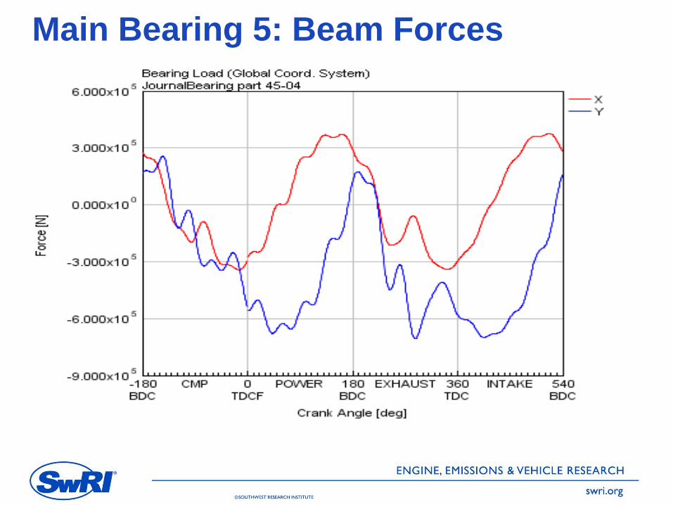
Main Bearing 5: Beam Forces

Advance Science. Applied Technology
With clockwise crankshaft rotation, the
figures shown are the ‘X’ and ‘Y’ load
components at rod bearings 1 and 9
(upper and lower left respectively), and
main bearing 1 (below)

Advance Science. Applied Technology
Each rod bearing shows the combination of reciprocating and rotating forces, creating repeating load cycles.

Advance Science. Applied Technology
Superimposed on the kinematic forces are the firing forces for cylinders 1 and 9

Advance Science. Applied Technology
The main bearing force components are a summation of those from each adjacent rod. End mains in a vee engine see forces from two rods. Interior mains see those from four rods.
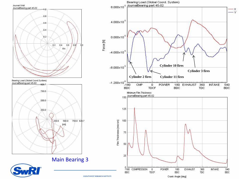
Main Bearing 3
Cylinder 3 fires
Cylinder 11 fires
Cylinder 10 fires
Cylinder 2 fires

Main Bearing 4
Cylinder 3 fires Cylinder 11 fires Cylinder 12 fires
Cylinder 4 fires

Cylinder Pressure
MOFT is most impacted, not from the pressure of an
individual cylinder, but when adjacent combustion
events are “stacked”
With initial firing order all main bearings see stacked
combustion events, and similar MOFT
With revised firing order the 3,5, and 7 main
bearings see stacked combustion events
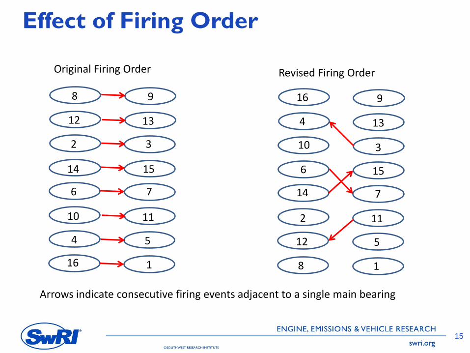
Effect of Firing Order
15
1
2 3
4 5
6 7
8 9
10 11
12 13
14 15
16 1
2
3
4
5
6
7
8
9
10
11
12
13
14
15
16
Original Firing Order Revised Firing Order
Arrows indicate consecutive firing events adjacent to a single main bearing

Hull Deflection Several recent publications discuss the impact of hull deflection on
main bearing loads
– Sverko, D., “Effect of the Hull Deflections on Propulsion System Bearing
Loading,” Paper No. 236, CIMAC 2007, Vienna.
– Sugimoto, I., Naka, T., “Optimization of Both Engine and Shaft
Alignment for Hull Deflection,” Paper No. 160, CIMAC 2007, Vienna
– Vartdal, B.J., “The Influence of Hull Deflection and Propeller Loading on
Load Distribution in Engine Bearings,” Paper No. 233, CIMAC 2010,
Bergen.
At large hull deflection magnitude failures are reported. On the order of 7 to 8mm between adjacent main bearings.
Another aspect of this project included block and hull deflection analysis. Even in high seas it was determined not to be a concern. Dynamic main bearing movement was considered but not pursued.
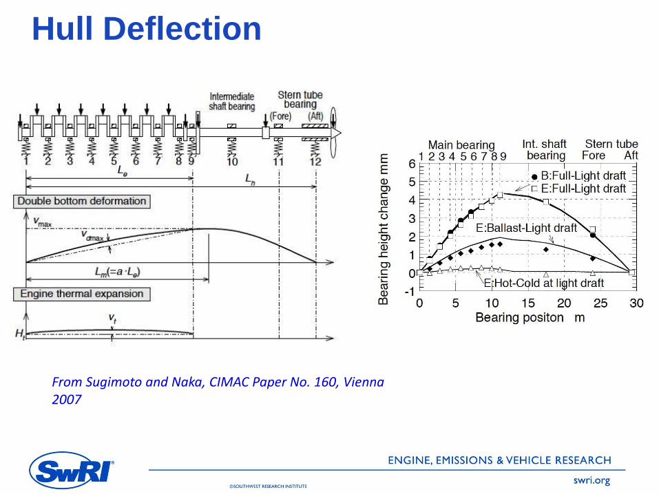
Hull Deflection
From Sugimoto and Naka, CIMAC Paper No. 160, Vienna 2007
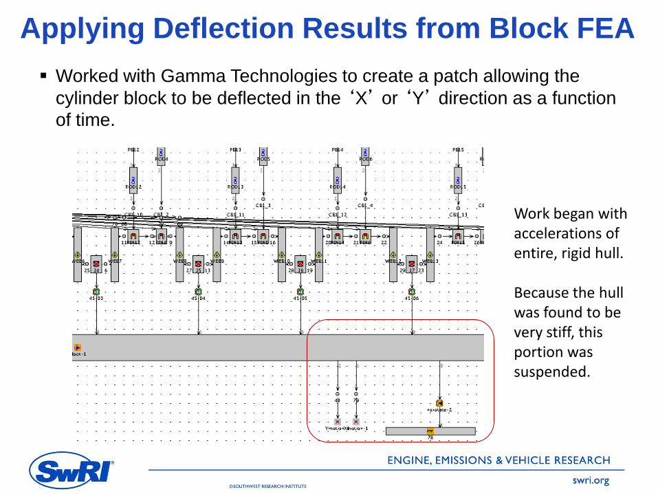
Applying Deflection Results from Block FEA
Worked with Gamma Technologies to create a patch allowing the
cylinder block to be deflected in the ‘X’ or ‘Y’ direction as a function
of time.
Work began with accelerations of entire, rigid hull. Because the hull was found to be very stiff, this portion was suspended.
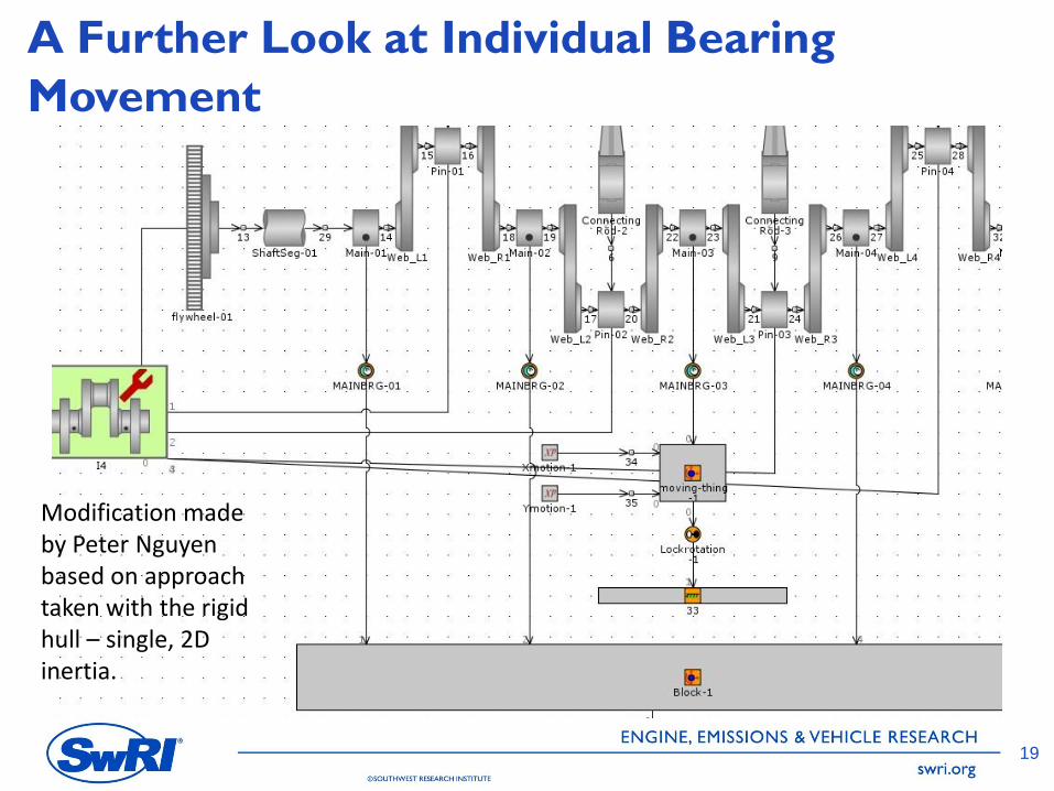
A Further Look at Individual Bearing
Movement
19
Modification made by Peter Nguyen based on approach taken with the rigid hull – single, 2D inertia.
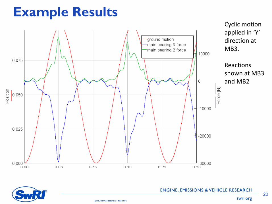
Example Results
20
Cyclic motion applied in ‘Y’ direction at MB3. Reactions shown at MB3 and MB2
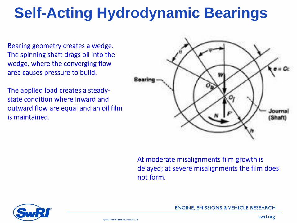
Self-Acting Hydrodynamic Bearings
Bearing geometry creates a wedge. The spinning shaft drags oil into the wedge, where the converging flow area causes pressure to build. The applied load creates a steady-state condition where inward and outward flow are equal and an oil film is maintained.
At moderate misalignments film growth is delayed; at severe misalignments the film does not form.
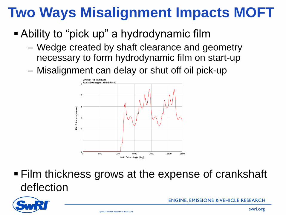
Two Ways Misalignment Impacts MOFT
Ability to “pick up” a hydrodynamic film – Wedge created by shaft clearance and geometry
necessary to form hydrodynamic film on start-up
– Misalignment can delay or shut off oil pick-up
Film thickness grows at the expense of crankshaft
deflection
Further Notes on Force Magnitude
Vertical bore misalignment is absorbed in two
locations: – Bearing film thickness reduction
– Bending deformation of the beam
At the end mains, 0.1mm of misalignment increased
bearing loads by ~4000 N (+0.8%)
At the center mains, 0.1mm of misalignment
increased bearing loads by ~28000 N (+4.3%)

Oil Film Development
Aligned Bearings

Oil Film Development
Misaligned Bearings
Worst Case Misalignment Combinations
In the following cases, adjacent main bearings were
simultaneously misaligned in opposite directions:
Case 1: – MB 2 vertically misaligned +0.1mm
– MBs 1 and 3 vertically misaligned -0.1mm
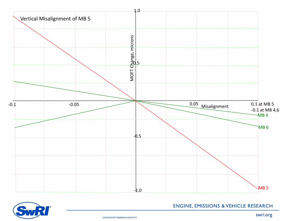
Case 2:
– MB 5 vertically misaligned +0.1mm
– MBs 4 and 6 vertically misaligned -0.1mm
Results were nearly linear with misalignment

0.1 at MB 2 -0.1 at MB 1,3
0.05 -0.1 -0.05 Misalignment
MO
FT C
han
ge, m
icro
ns
-0.5
-1.0
0.5
1.0
MB 2 MB 1
Vertical Misalignment of MB 2
MB 3
0.05 -0.1 -0.05 Misalignment
MO
FT C
han
ge, m
icro
ns
-0.5
-1.0
0.5
1.0
MB 5
MB 6
Vertical Misalignment of MB 5
MB 4
0.1 at MB 5 -0.1 at MB 4,6
Further Parameters
Torsional Vibration – In the absence of damping performance data, a
sweep from zero to maximum damping was done
– Angular deflection varied from 0.4 to 1.4 degrees CA
– No measurable difference in MOFT
Filtration Efficiency
– Not directly addressed
– Specifications based on correlation to MOFT
Oil temperature
– Greatest impact
– Monitored at every bearing
Summary
GT Suite used in conjunction with 3-D FEA allowed evaluation
of a wide range of parameters
Further capabilities for time-dependent bearing movement are
being explored
SwRI expresses our thanks to Peter Nguyen and his colleagues
for ideas, guidance, and modifications needed along the way.
30

31