MAHARASHTRA STATE ELECTRICITY DISTRIBUTION CO. LTD. KWH-KVAH.pdf · to test the meter, the pulse...
24
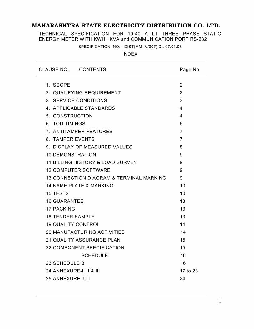
1 MAHARASHTRA STATE ELECTRICITY DISTRIBUTION CO. LTD. TECHNICAL SPECIFICATION FOR 10-40 A LT THREE PHASE STATIC ENERGY METER WITH KWH+ KVA and COMMUNICATION PORT RS-232 SPECIFICATION NO:- DIST(MM-IV/007) Dt. 07.01.08 INDEX CLAUSE NO. CONTENTS Page No 1. SCOPE 2 2. QUALIFYING REQUIREMENT 2 3. SERVICE CONDITIONS 3 4. APPLICABLE STANDARDS 4 5. CONSTRUCTION 4 6. TOD TIMINGS 6 7. ANTITAMPER FEATURES 7 8. TAMPER EVENTS 7 9. DISPLAY OF MEASURED VALUES 8 10. DEMONSTRATION 9 11. BILLING HISTORY & LOAD SURVEY 9 12. COMPUTER SOFTWARE 9 13. CONNECTION DIAGRAM & TERMINAL MARKING 9 14. NAME PLATE & MARKING 10 15. TESTS 10 16. GUARANTEE 13 17. PACKING 13 18. TENDER SAMPLE 13 19. QUALITY CONTROL 14 20. MANUFACTURING ACTIVITIES 14 21. QUALITY ASSURANCE PLAN 15 22. COMPONENT SPECIFICATION 15 SCHEDULE 16 23. SCHEDULE B 16 24. ANNEXURE-I, II & III 17 to 23 25. ANNEXURE U-I 24
Transcript of MAHARASHTRA STATE ELECTRICITY DISTRIBUTION CO. LTD. KWH-KVAH.pdf · to test the meter, the pulse...
1
MAHARASHTRA STATE ELECTRICITY DISTRIBUTION CO. LTD.
TECHNICAL SPECIFICATION FOR 10-40 A LT THREE PHASE STATIC ENERGY METER WITH KWH+ KVA and COMMUNICATION PORT RS-232
SPECIFICATION NO:- DIST(MM-IV/007) Dt. 07.01.08
INDEX
CLAUSE NO. CONTENTS Page No
1. SCOPE 2
2. QUALIFYING REQUIREMENT 2
3. SERVICE CONDITIONS 3
4. APPLICABLE STANDARDS 4
5. CONSTRUCTION 4
6. TOD TIMINGS 6
7. ANTITAMPER FEATURES 7
8. TAMPER EVENTS 7
9. DISPLAY OF MEASURED VALUES 8
10. DEMONSTRATION 9
11. BILLING HISTORY & LOAD SURVEY 9
12. COMPUTER SOFTWARE 9
13. CONNECTION DIAGRAM & TERMINAL MARKING 9
14. NAME PLATE & MARKING 10
15. TESTS 10
16. GUARANTEE 13
17. PACKING 13
18. TENDER SAMPLE 13
19. QUALITY CONTROL 14
20. MANUFACTURING ACTIVITIES 14
21. QUALITY ASSURANCE PLAN 15
22. COMPONENT SPECIFICATION 15
SCHEDULE 16
23. SCHEDULE B 16
24. ANNEXURE-I, II & III 17 to 23
25. ANNEXURE U-I 24

2
Maharashtra State Electricity Distribution Co.Ltd. Technical Specification for10-40 A LT Three Phase Static Energy Meters
With KWH+ KVA and Communication Port RS-232 Specification No. DIST (MM-IV/007) DT. 07.01.08
1.0 SCOPE:-
This specification covers the design, manufacture, testing and supply of ISI marked 10-40 A LT Three Phase Static TOD Energy Meters suitable for
measurement of Energy (kWh) and kVAMD in 3 phase, 4 wire balanced / unbalanced loads of LT Consumers.
2.0 QUALIFYING REQUIREMENTS :-
2.1 I] Offers of only original manufacturers of L.T.A.C. Static Energy Meters shall be
accepted against the Tender.
II] The following qualifying requirement shall be fulfilled by the bidders/
manufacturers
a) The bidder/manufacturer should have turnover of Rs.80 crores during any one
of the last three financial years.
b) The bidder/manufacturer should have supplied of 12.5 lakhs static meters during the last three financial years.
c) The bidder/manufacturer should have minimum experience of three years of supply or manufacturing for static meters upto the end of the last financial year.
III] The offers of Indian subsidiary company, whose parent company is located
abroad fulfilling the qualifying requirements shall be considered provided the
Indian participant subsidiary company fulfils the minimum experience of three
years of supply or manufacturing for static energy meters upto the end of the
last financial year. However, the conditions of turnover of Rs.80 crores during
any one of the last three financial years and supply of minimum quantity of 12.5
lakhs static energy meters during last three financial years can be fulfilled by
the parent company located in abroad on behalf of their Indian subsidiary
company. The parent company shall furnish undertaking for accepting
responsibility for supplying quality meters as per specifications and
execution of the contract on behalf of its India based subsidiary unit who has
participated in the tender in Annexure – U1
v] MINIMUM TESTING FACILITIES
Manufacturer should posses fully computerized Meter Test Bench System for carrying out routine and acceptance Tests as per IS 13779/1999

3
(amended up to date). In addition this facility should produce Test Reports for each and every meter. The list of testing equipments shall be enclosed.
The manufacturer should have the necessary minimum testing facilities for carrying out the following tests:
1) Insulation resistance measurement
2) No load condition
3) Starting current test
4) Accuracy requirement
5) Power consumption in voltage circuit
6) Repeatability of error
7) Transportation test – as per clause no. 15.03(a) of MSEDCL specification
8) Tamper conditions - as per clause no. 8.00 of MSEDCL specification.
9) Shock and Vibration Test.
10) The manufacturer should have duly calibrated RSS meter of class 0.1 or better accuracy. The bidder should have fully automatic Test Bench having in-built constant voltage, current and frequency source with facility to select various loads automatically and print the errors
directly.
vi] Meter Software The Bidders will have to get appraised & obtain CMMI – Level III within One year from date of letter of award.
3.00 SERVICE CONDITIONS
The meters to be supplied against this specification shall be suitable for satisfactory continuous operation under the following tropical conditions:
3.01 Environmental Condition
Maximum ambient temperature (degree C) 55
Maximum ambient temperature in shade (degree C) 45
Maximum temperature of air in shade (degree C) 35
Maximum daily average temperature (degree C) 40
Maximum yearly weighted average temperature (degree C) 32
Relative Humidity (%) 10 to 95
Maximum Annual rainfall (mm) 1450
Maximum wind pressure (Kg/sqm) 150
Maximum altitude above mean sea level (meters) 1000
Isoceraunic level (days / year) 50
Seismic level (Horizontal acceleration) 0.3g
Climate:- Moderately hot and humid tropical climate
Conducive to rust and fungus growth

4
3.02 Current & Voltage Rating
• The current rating shall be 10-40A. Rated basic current (Ib) for L.T. Energy Meters shall be 10A per phase and the maximum continuous
current (Imax) shall be 400% of rated basic current.
• The meters shall work accurately at 150% of Imax.
• The starting current for the meter should be 0.2% of Ib
• The rated voltage shall be 3x240 volts. The voltage range shall be (+) 20% to (– ) 40% of rated voltage.
3.03 Temperature
The standard reference temperature for performance shall be 27 degree C. The mean temperature co-efficient should not exceed 0.07%.
3.04 Frequency
The rated frequency shall be 50 Hz with a tolerance of +/- 5%.
3.05 Power factor range Zero Lag – Unity – Zero lead.
• For leading Power factor the value of kVAh should equal to kWh, for the
Purpose of calculation of average power factor (on the basis of kWh/kVAh)
i.e. The value of kVAh shall be based on lagging value of kVARh and
kWh..
3.06 Power consumption - less than 1Watt and 4 VA /phase in voltage circuit and 2 VA in current circuit.
4.00 APPLICABLE STANDARD
The Meters shall conform to IS 13779/1999 (amended up to date) and other relevant IS specifications and CBIP Tech-report-88 amended up to date. The specification given in this document supersedes the relevant clauses of relevant standard specifications wherever applicable.
• The meter shall bear ISI mark.
• The class of accuracy of the Energy Meter shall be 1.0.
5.00 CONSTRUCTION
5.01 The meter shall be projection type and should be dust and moisture proof. The cover shall be made out of such material so as to give it tough and
non-breakable qualities and shall be secured to base by means of sealable captive screws. The meter body shall be type tested for IP51 degree of protection.
5.02 Moulded terminal block for current and voltage connections conforming to IS
13779/1999(amended up to date) to meet the requirement of terminal connection
arrangement shall be provided. The termination arrangement shall be provided
with an extended transparent terminal cover as per clause number 6.5.2 of IS

5
13779 and shall be sealable independently to prevent unauthorized tampering.
Proper size of grooves should be provided at bottom of this terminal cover for
incoming and outgoing service wires.
5.03 All insulating materials used in the construction of the meter shall be substantially non-hygroscopic, non aging and of tested quality.
5.04 All parts that are likely to develop corrosion under normal working condition shall be effectively protected against corrosion.
5.05 The meter shall be pilfer-proof & tamper-proof. Sealing provision shall be made against opening of the terminal cover and front cover. It is necessary to provide unidirectional screws with two holes for sealing
purpose.
5.06 The meter shall have Poly-carbonate translucent base and transparent cover of Poly-carbonate- material, which shall be ultra-sonically welded (continuous welding) so that once the meter is manufactured and tested at factory, it should not be possible to open the cover at site except the
terminal cover. The thickness of material for meter cover and base shall be 2 mm (minimum).
5.07 The real time quartz clock shall be used in the meter for maintaining time (IST) and calendar. Facility for adjustment of real time should be provided through CMRI with proper security.
5.08 The meter shall be completely factory sealed except the terminal block cover. The provision shall be made on the Meter for at least two seals to be put by utility user. The Terminal cover should be transparent with one side hinge with sealing arrangement.
5.09 The blinking LED or other similar device like blinking LCD shall be provided to test the meter, the pulse rate of which either Pulse/kWH and pulse/kVARH ( meter constant ) should be indelibly provided on the name plate.
5.10 The meter accuracy shall not be affected by magnetic field (AC/DC/Permanent) upto 0.2 Tesla on all the sides of meter i.e. front, sides, top and bottom of the meter as per CBIP-88 Technical Report with latest amendments. Under influence of any magnetic field (AC/DC/Permanent) above 0.2 Tesla, meter shall record energy considering Imax and reference voltage at unity power factor.
5.11 Meter shall have CTS with magnetic shielding and same should be tested separately.
5.12 The meter shall also be capable to withstand and shall not get damaged if phase to phase voltage is applied between phase to neutral for 5 minutes.
5.13 In meter, Power supply unit should be micro control type instead of providing transformer and then conversion to avoid magnetic influence.
5.14 The RTC battery & the battery for display in case of power failure should be separate.
5.15 Non specified display parameter in the meter should be blocked and same should not be accessible for reprogramming at site.

6
5.16. Complete metering system should not be affected by the external electromagnetic interference such as electrical discharge of cables and capacitors, harmonics, electrostatic discharges, external magnetic fields and DC current in AC supply etc. The Meter shall meet the requirement of CBIP Tech-report 88 (amended up to date).
5.17 The accuracy of the meter should not be affected with the application of abnormal voltage/frequency generating device such as spark discharge of approximately 35 KV. The meter shall be tested by feeding the output of this device to meter in any of the following manner for 10 minutes:
i) On any of the phases or neutral terminals
ii) On any connecting wires of the meter (Voltage discharge with 0-10 mm spark gap)
iii) At any place in load circuit
The accuracy of meter shall be checked before and after the application of above device.
5.18 The meter should have facility for Data Retrieval through optical port using CMRI or Laptop PC and Wired RS-232 (RJ-11 type is also acceptable) communication port for remote meter reading facility. RS-232 port on
terminal block is also acceptable. Sealing arrangement for both Optical & RS-232 ports shall be provided.
5.19 Self Diagnostic Features:- a).The meter shall keep log in its memory for
unsatisfactory / non functioning of Real Time Clock battery and can be
downloaded for reading through MRI to read in base computer.
b) "LED/LCD Test" display shall be provided for checking of all display
Segments.
5.20 The meter shall have facility to read the default display parameters during
Power supply failure. An internal maintenance free battery (Ni-mh or Li-ion
or NI CD) of long life of 15 years shall be provided for the same. A suitable
Push Button arrangement for activation of battery shall be provided. This
battery may be of external type with inductive coupling arrangement.
External Battery is to be provided with inbuilt charger, in the ratio of
one battery pack per 50 nos. meters.
5.21 Wire/Cable less design. The meter PCB should be wire less to avoid
improper and loose connections / contacts.
5.22 PCB used in meter shall be made by Surface Mounting Technology.
6.00 TOD TIMINGS
There shall be provision for at least 6 (Six) TOD time zones for energy and demand. The number and timings of these TOD time Zones shall be programmable.
7
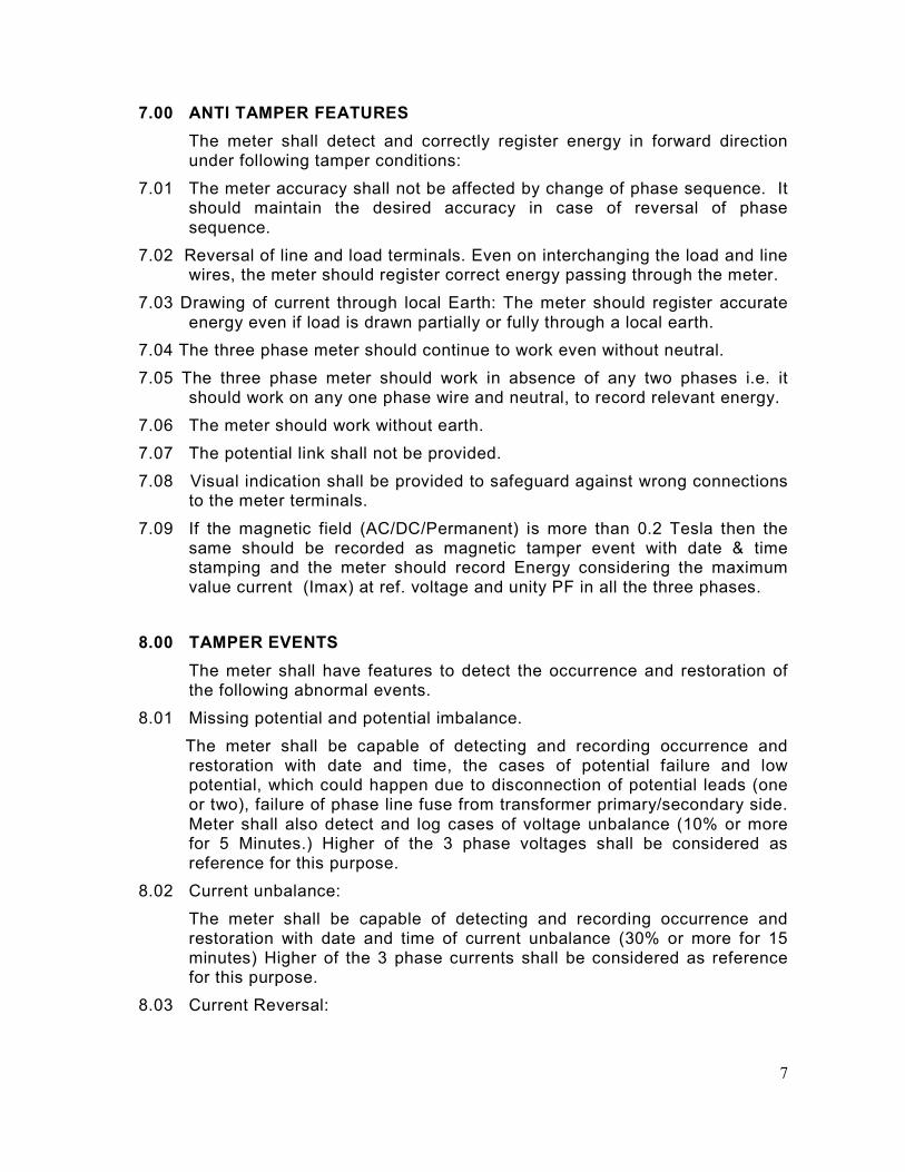
7.00 ANTI TAMPER FEATURES
The meter shall detect and correctly register energy in forward direction under following tamper conditions:
7.01 The meter accuracy shall not be affected by change of phase sequence. It should maintain the desired accuracy in case of reversal of phase
sequence.
7.02 Reversal of line and load terminals. Even on interchanging the load and line wires, the meter should register correct energy passing through the meter.
7.03 Drawing of current through local Earth: The meter should register accurate
energy even if load is drawn partially or fully through a local earth.
7.04 The three phase meter should continue to work even without neutral.
7.05 The three phase meter should work in absence of any two phases i.e. it should work on any one phase wire and neutral, to record relevant energy.
7.06 The meter should work without earth.
7.07 The potential link shall not be provided.
7.08 Visual indication shall be provided to safeguard against wrong connections to the meter terminals.
7.09 If the magnetic field (AC/DC/Permanent) is more than 0.2 Tesla then the same should be recorded as magnetic tamper event with date & time stamping and the meter should record Energy considering the maximum value current (Imax) at ref. voltage and unity PF in all the three phases.
8.00 TAMPER EVENTS
The meter shall have features to detect the occurrence and restoration of the following abnormal events.
8.01 Missing potential and potential imbalance.
The meter shall be capable of detecting and recording occurrence and restoration with date and time, the cases of potential failure and low potential, which could happen due to disconnection of potential leads (one or two), failure of phase line fuse from transformer primary/secondary side.
Meter shall also detect and log cases of voltage unbalance (10% or more for 5 Minutes.) Higher of the 3 phase voltages shall be considered as reference for this purpose.
8.02 Current unbalance:
The meter shall be capable of detecting and recording occurrence and restoration with date and time of current unbalance (30% or more for 15 minutes) Higher of the 3 phase currents shall be considered as reference for this purpose.
8.03 Current Reversal:

8
The meter shall be capable of detecting and recording occurrence and restoration with date and time of reversal of current with phase identification for persistence time of 5 minutes.
8.04 High Neutral Current. (CT bypass)
The meter shall be capable of recording incidences of excess neutral current (if it is in excess 30% of Ib for more than 5 minutes.)
The meter shall record the total duration of the above abnormalities, time and date of their occurrences and restorations with snapshot of instantaneous electrical conditions viz. System Voltages, phase Currents & System PF.
8.05 Power ON / OFF
The meter shall be capable to record power ON/OFF events in the meter memory. All potential failure should record as power off event.
The meter shall keep records for the minimum 280 events. (Occurrence + Restoration). For above abnormal conditions the recording of events shall
be on FIFO basis. It shall be possible to retrieve the abnormal event data along with all related snap shots data through the meter optical port with the help of CMRI & downloaded the same to the base computer . All the information shall be made available in simple & easy to understand format.
8.06 Current circuit short :-The meter shall be capable of detecting and recording occurrences and restoration of shorting of any one or two phases of current.
8.07 In the event the meter is forceably opened, even by one degree variation of the
meter top cover, same should be recorded as tamper event with date & time stamping and the meter should continuously display in autoscroll mode that the cover has been tampered. It is suggested that the manufacturer should develop their software such that there will be some time delay for activation of this tamper feature and during that period only the meter cover should be fitted. The delay in activation of software shall be for one instance only. After the meter cover is fitted, it shall get activated immediately with out any delay.
9.00 DISPLAY OF MEASURED VALUES
9.01 The display shall be permanently backlit LCD. The display shall be minimum full 5 digit type display. The size of digit should be minimum 10X5 mm. The decimal units shall not be displayed. The adequate back up
arrangement for storing of energy registered at the time of power
interruption shall be provided.
9.02 The display parameters will be preprogrammed at factory as per Annexure-II & the scroll period for auto scroll should be 9 sec.
The meter should Auto reset kVAMD at 24.00 Hrs. of last day of the month and this value shall be stored in the memory along with the cumulative kWH reading. No reset push button shall be provided.
The display order shall be as per Annexure -II in addition to the above parameters.
9
9.03 Maximum Demand Integration Period:-Integration period for kVAMD should be of 30 minutes real time based. However same shall be programmable to 15 minutes if required.
10.00 DEMONSTRATION
The purchaser reserves the right to ask to give the demonstration of the equipment offered at the purchaser’s place.
11.00 BILLING HISTORY & LOAD SURVEY
The meter shall have sufficient non-volatile memory for recording history of billing parameters (Cumulative kWh at the time of reset and kVAMD) for last 6 months.
11.01 Load survey parameters :- kWh , kVAh
The logging interval for load survey shall be 30 minutes. Load survey data shall be logged for last 60 days on non time based basis. i.e. if there is no power for more than 24 hours, the day should not be recorded Whenever meter is taken out and brought to laboratory the L/S data shall be retained for the period of actual use of meter. This load survey data can be retrieved as and when desired and load profiles shall be viewed graphically / analytically with the help of meter application software. The meter application software shall be capable of exporting / transmitting these data for analysis to other user software in spreadsheet format.
12.00 COMPUTER SOFTWARE.
For efficient and speedy recovery of data downloaded through CMRI on base computer, licensed copies of base computer software shall have to be supplied free of cost. This software will be used at number of places up to Division level.
The computer software shall be "Window" based & user friendly. The data transfer shall be highly reliable and fraud proof (No editing shall be possible on base computer by any means).The software shall have
capability to convert all the data into ASCII format.
As many copies of base computer software as required up to Division level shall be provided by Supplier.
The protocol used in the meter shall have to be provided at the time of supply for the purpose of Automatic Meter Reading System.
13.00 CONNECTION DIAGRAM AND TERMINAL MARKINGS.
The connection diagram of the meter shall be clearly shown on inside
portion of the terminal cover and shall be of permanent nature. Meter terminals shall also be marked and this marking should appear in the above diagram. The diagram & terminal marking on sticker will not be allowed.
10
14.00 NAME PLATE AND MARKING
Meter shall have a name plate clearly visible, effectively secured against removal and indelibly and distinctly marked with all essential particulars as per relevant standards. Meter Serial Number shall be Bar Coded along with numeric number. The size of bar coded number should not be less than 35x5 mm. The manufacturer’s meter constant shall be marked on the name plate. Meter serial number & bar code on sticker will not be allowed.
In addition to the requirement as per IS following shall be marked on the name plate.
1) Purchase order No & date.
2) Month and Year of manufacture.
3) Name of purchaser i.e. MSEDCL.
4) Guarantee Five Years.
5) ISI mark.
15.00 TESTS
15.01 Type Tests
Meter shall be fully type tested as per IS 13779/1999(amended up to date)
and external AC/DC magnetic influence tests as per CBIP Tech-Report 88 with latest amendments. The Type Test Reports shall clearly indicate the constructional features of the type tested meters. Separate type Test Reports for each offered type of meters shall be submitted. All the Type
Tests shall be carried out from Laboratories which are accredited by the National Board of Testing and Calibration Laboratories (NABL) of Govt. of India such as CPRI, Bangalore / Bhopal, ERDA Baroda, to prove that the meters meet the requirements of specification. Type Test Reports conducted in manufacturers own laboratory and certified by testing institute shall not be acceptable. The tenderer should also furnish the particulars
giving specific required details of Meters in schedule A attached. The offers without the details in Schedule ‘A’ stand rejected.
Type test reports should be submitted along with offer. The type test report of meter having identical constructional and other features carried out during last three years will be valid. the type test report of 10-60A meters shall
also be considered as the clause no. 3.02 states “Meter should work accurately at 150% of Imax”. As such the type test report of either 10-40 A or 10-60A will be acceptable The purchaser reserves the right to demand repetition of some or all the type tests in presence of purchaser’s representative at purchaser’s cost.
15.02 Meters shall pass all the acceptance and routine tests as laid down in IS: 13779/1999( amended up to date) and also additional acceptance tests as prescribed in this specification. (3 to 8 meters from a lot more than 1000
will be sealed randomly in the factory and will be tested for tamper
events).

11
15.03 Additional Acceptance Tests:
The following additional tests shall be carried out in addition to the acceptance tests specified in IS 13779/1999 (amended up to date)
15.03.a) Transportation Test:
At least 50% of the samples of the meters be tested for error at Imax, Ib and 5% Ib at unity power factor and 50% Imax and 10% Ib at 0.5 lagging
Power Factor besides checking them for starting current. This test shall be conducted on ready to install meter i.e. meter cover ultrasonically welded & sealed. After recording these errors, the meters be put in their normal packing and transported for at least 50 km in any transport vehicle such as pick up van, Jeep, etc. on uneven rural roads and then re-tested at all these loads after the transportation. The variation in errors recorded before and after transportation should not exceed 1% at higher loads and 1.5% at loads below Ib.
15.03 b) Other Acceptance Test
i) The meter shall withstand continuously for a period of at least 5 minutes at a voltage of 440 V between phase and neutral without damage/problems.
ii) Meters shall be tested for tamper conditions as stated in this specification.
iii) Glow wire testing for poly-carbonate body.
iv) Power consumption tests shall be carried out.
v) The meter shall comply all the test for external AC/DC magnetic field as per CBIP Tech Report 88 with latest amendments. Moreover, the
magnetic influence test for permanent magnet of 0.5 Tesla for minimum period of 15 minutes shall be carried out. After removal of magnet , meter shall be subjected to accuracy test as per IS 13779/1999 (amended up to date). No deviation in error is allowed in the accuracy as per specification.
vi) The meter shall withstand impulse voltage at 10 kV.
The test 15.03(b) (i) to (iv) shall be carried out at factory for each inspected lot at the time of pre dispatch inspection.
The tests 15.03 b) (v) & (vi) shall be carried out on one sample from first
lot as per procedure laid down in IS13779/1999( amended up to date) and CBIP Tech-Report 88.( with latest amendments) in NABL LAB. The test report shall be got approved from CE(Dist.) before commencement of supply.
15.03 c) Limits of error
i) Limits of variation in percentage error due to change in voltage shall not exceed the values given in the following table:
Influence quantities Value of current (Balanced unless: Otherwise stated
Power factor
Limits of variation in % error for class

12
1 meters
a) Voltage variation between – 15% to +10%
Ib
Ib 1 0.5 lag
0.7 1.0
b) Voltage variation
between – 40%, + 20% and + 10%
Ib
Ib
1
0.5 lag
1.1
1.5
ii) The meters shall be tested at (-) 15% and at (-) 40% of reference voltage as well as (+) 10% and (+) 20% of reference voltage and shall record energy within limits of variation indicated above.
iii) For other influence quantities like frequency variation, voltage unbalance etc. the limits of variation in percentage error will be as per IS:13779/1999.( amended up to date)
15.04 PRE DESPATCH INSPECTION
All Acceptance tests and inspection shall be carried out at the place of manufacturer unless otherwise specially agreed upon by the manufacturer and purchaser at the time of purchase. The manufacturer shall offer to the inspector representing the purchaser, all the reasonable facilities, free of charge, for inspection and testing, to satisfy him that the material is being supplied in accordance with this specification.The MSEDCL’s representative / Engineer attending the above testing will carry out testing on suitable number of meters as per sampling procedure laid down in IS 13779/1999 (amended up to date) and additional acceptance test as per this specification and issue test certificate approval to the manufacturer and give clearance for dispatch. The meters shall be sealed after inspection at works.
The first lot of meter may be jointly inspected by the representative of the Chief Engineer (Distribution) and the Executive Engineer (INSPECTION
WING).
15.05 INSPECTION AFTER RECEIPT AT STORES
(Random Sample Testing)(Random Sample Testing)(Random Sample Testing)(Random Sample Testing)
“For carrying out ‘Random Sample Testing’ (RST), the sample meters will
be drawn from any one of the stores against inspected lot. Sample meters
shall be drawn as per Appendix ‘C’ of IS 13779/1999 (amended up to date)
Sample meters will be tested by MSEDCL Testing Engineer in presence of
supplier’s representative jointly for (i) starting current, (ii) Limits of error, (iii)
Repeatability of error (iv) No Load Test as IS 13779 / 1999 (amended up to
date) The RST shall be carried out at Testing Division Bhandup. The 5 days
advance intimation will be given to the supplier and if the

13
Supplier fails to attend the joint inspection on the date informed , the
testing will be carried out by our testing Engineer in absence of supplier’s
representative. If the meters failed in above random sample testing, the lot
will be rejected.”
16.00 GUARANTEE
The meter shall be guaranteed for the period of five years from the date of commissioning or five and half year from the date of dispatch whichever is earlier. The meter found defective within above guarantee period shall he replaced / repaired by the supplier free of cost, within one month of receipt of intimation. If defective meters are not replaced / repaired within the specified period as above, the MSEDCL shall recover an equivalent amount plus 15% supervision charges from any of the bills of the supplier.
17.00 PACKING
17.01 The meters shall be suitably packed in order to avoid damage or
disturbance during transit or handling. Each meter may be suitably packed in the first instance to prevent ingress of moisture and dust and then placed in a cushioned carton of a suitable material to prevent damage due to shocks during transit. The lid of the carton may be suitably sealed. A suitable number of sealed cartons may be packed in a case of adequate
strength with extra crushing, if considered necessary. The cases may then be properly sealed against accidental opening in transit. The packing cases may be marked to indicate the fragile nature of the contents.
17.02 The following information shall be furnished with the consignment:
- Name of the consignee
- Details of consignment
- Destination
- Total weight of the consignment
- Sign showing upper / lower side of the crate
- Sign showing fragility of the material
- Handling and unpacking instructions
- Bill of Materials indicating contents of each package and spare
materials
18.00 TENDER SAMPLE
Tenderers are required to submit 10 nos. of meter samples of each offered
type / item as per technical specification of tender document , from any one of the factories on or before the time and date stipulated for submission of

14
offer , for evaluations. The samples shall be clearly marked with each type / item for which sample submitted and name of bidder. Out of these,Two samples should be without ultrasonic welding to confirm constructional features.
19.00 QUALITY CONTROL
The purchaser has a right to send a team of experienced engineers for assessing the capability of the firm for manufacturing and testing of meters as per this specification. The item should be given all assistance and cooperation for inspection and testing at the bidder’s work
20.00 MANUFACTURING ACTIVITIES
20.01 The manufacturer shall submit the list of plant and machinery along with the offer.
20.02 Meter should be manufactured using SMT (Surface Mount Technology) components and by deploying automatic SMT pick and place machine and reflow solder process. Further, the Bidder should own or have assured access (through hire, lease or sub-contract, documentary proof shall be attached with the offer) of above facilities.
20.03 Quality should be ensured at the following stages.
20.03.01 At PCB manufacturing stage, each Board shall be subjected to computerized bare board testing.
20.03.02 At insertion stage, all components should under go computerized
testing for conforming to design parameters and orientation
20.03.03 Complete assembled and soldered PCB should under go functional testing using Automatic Test Equipments (ATEs).
20.03.04 Prior to final testing and calibration, all meters shall be subjected to
aging test (i.e. Meters will be kept in ovens for 72 hours at 55 deg C temperature & at full load current. After 72 hours meters should work satisfactory) to eliminate infant mortality.
20.04 The calibration of meters shall be done in-house.
20.05 The bidders should submit the list of all imported and indigenous
components separately used in meter along with the offer.
20.06 Bought out items
A detailed list of bought out items which are used in the manufacturing of the meter should be furnished indicating the name of firms from whom these items are procured. The bidder shall also give the details of quality assurance procedures following by him in respect of the bought out items.

15
Sr. No.
List of Plant and Machinery used for Energy meter Production
1 Fully automatic testing Bench with ICT for testing linkless meters
Routine Testing and Calibration of Meters
2 Semi automatic testing Bench with MSVT Routine Testing and Calibration of Meters
3 IR Tester Insulation testing
4 HV Tester Insulation testing
5 Error calculators Error testing
6 Long duration Running test set ups Reliability Testing
7 Reference Meters Cl 0.01 accuracy Error calculation
8 Ultrasonic welding Machines Welding of meters
9 Automatic Pick and Place Machines Automatic placing of SMT components
10 Solder Paste Printing Machine SMT soldering
11 Soldering Furnace IR reflow SMT soldering
12 PCB Scanner For testing of PCBs
13 ATE functional tester For testing of Components
14 Programmers and Program Loaders Chip Programming Tools
15 CAD PCB designing setups PCb designing
16 Furnace IR type for Hybrid Micro Circuits resistance network and HMC manufacturing
17 Laser Trimming Machines trimming of resistances for higher accuracy measurement
18 Wave Soldering Machines Wave soldering of PCBs
19 Humidity Chamber Accelerated testing for Life cycle
20 Dry Heat Test Chamber Accelerated testing for Life cycle
21 Thermal Shock Chamber Accelerated testing for Life cycle
22 PRO -E Mechanical Design Stations Mechanical CAD stations
23 Spark Erosion Tool fabricating Machine Tool fabrication and Die manufacturing
24 CNC wire Cut Tool Fabrication machine Tool fabrication and Die manufacturing
25 CNC Milling Machine for composite tool fabrication Tool fabrication and Die manufacturing
26 Injection Moulding Machine Moulding of plastic parts
27 Vibration testing Machine Vibration testing of Meters
28 Glow Wire Test machine Testing of Plastic Material
29 Fast transient burst testing setup Type testing of Meters
30 Short term over Current testing setup Type testing of Meters
31 Magnetic and other tamper testing setups Tamper Testing
32 Impulse Voltage Testing Setup Type testing of Meters
33 Composite Environmental testing chambers Type testing of Meters
21.00 QUALITY ASSURANCE PLAN
21.01 The tenderer shall invariably furnish QAP as specified in Annexure-I along with his offer the QAP adopted by him in the process of manufacturing.
21.02 Precautions taken for ensuring uses of quality raw material and sub-
component shall be stated in QAP
22.00 The COMPONENT SPECIFICATION as per Annexure -III enclosed..

16
23.00 SCHEDULES:-
The tenderer shall fill in the following schedules which are part and parcel of the tender specification and offer. If the schedules are not submitted duly filled in with the offer, the offer shall be liable for rejection.
Schedule `A' ... Guaranteed and technical particulars (As indicated in GTP parameters on E-Tendering)
Schedule `B' ... Tenderer's Experience
The discrepancies if any between the specification and the catalogs and/or literatures submitted as part of the offer by the bidders, the same shall not be considered and representations in this regard will not be entertained.
SCHEDULE - "B"
TENDERER’S EXPERIENCE
The Tenderer shall furnish list of similar order executed or under execution of supplying three phase static energy meters by him to whom a reference may be made by purchaser in case he consider such a reference necessary.
SR. NO. NAME OF ORDER NO. QTY. ORDERED QTY. SUPPLIED
CLIENT & DATE
NAME OF FIRM _______________________________________
NAME & SIGNATURE OF TENDERER_________________
DESIGNATION ________________________________________
DATE _______________________________________________

17
ANNEXURE- I
Quality Assurance Plan :
A) The bidder shall invariably furnish the following information alongwith his bid, failing which his bid shall be liable for rejection. Information shall be separately given for individual type of material offered.
i) Statement giving list of important raw materials, names of sub- suppliers for the raw materials, list of standards according to which the raw materials are tested. List of test normally carried out on raw materials in presence of
Bidder's representative, copies of test certificates :
ii) Information and copies of test certificates as in (i) above in respect of bought out accessories.
iii) List of manufacturing facilities available.
iv) Level of automation achieved and list of areas where manual processing exists.
v) List of areas in manufacturing process, where stage inspections are
normally carried out for quality control and details of such tests and inspections.
vi) List of testing equipment available with the bidder for final testing of equipment specified and test plan limitation. If any, vis-a-vis the type, special acceptance and routine tests specified in the relevant standards. These limitation shall be very clearly bought out in schedule of deviation from specified test requirements.
B) The successful bidder shall within 30 days of placement of order, submit
following information to the purchaser.
i) List of raw materials as well as bought out accessories and the names of sub-suppliers selected from those furnished alongwith offers.
ii) Type test certificates of the raw materials and bought out accessories if required by the purchaser.
iii) Quality assurance plan (QAP) with hold points for purchaser’s inspection.
The quality assurance plant and purchasers hold points shall be discussed between the purchaser and bidder before the QAP is finalized.
C) The contractor shall operate systems which implement the following :
i) Hold point: A stage in the material procurement or workmanship process beyond which work shall not proceed without the documental approval of designated individuals organizations. The purchaser’s written
approval is required to authorise work to progress beyond the hold points indicated in quality assurance plans.

18
ii) Notification point: A stage in the material procurement or workmanship process for which advance notice of the activity is required to facilitate witness. If the purchaser does not attend after receiving documented notification in accordance with the agreed procedures and with the correct period of notice then work may proceed.
D) The successful bidder shall submit the routine test certificates of bought out accessories and central excise passes for raw material at the time of
routine testing if required by the purchaser and ensure that Quality Assurance program of the contractor shall consist of the quality systems and quality plans with the following details.
i) The structure of the organization.
The duties and responsibilities assigned to staff ensuring quality of work.
The system for purchasing taking delivery and verification of material.
The system for ensuring quality workmanship.
The system for retention of records.
The arrangements for contractor are internal auditing.
A list of administration and work procedures required to achieve and verify contract's quality requirements these procedures shall be made readily available to the project manager for inspection on request.
ii) Quality Plans :
An outline of the proposed work and programme sequence.
The structure of the contractor's organization for the contract.
The duties and responsibilities assigned to staff ensuring quality of work.
Hold and notification points.
Submission of engineering documents required by the specification.
The inspection of materials and components on receipt.
Reference to the contractor's work procedures appropriate to each activity.
Inspection during fabrication/ construction.
Final inspection and test.

19
Annexure – II of 10-40 Amps. L.T. 3-Ph. Static Energy Meters with
communication port.
(A) Default Display ( With Scrolling time 9 sec.)
1. LCD Test
2. Date – Day/Month/Year
3. Time – Hrs:Min:Sec.
4. Cumulative kWh reading
5. Cumulative kWh reading TOD Zone A
6. Cumulative kWh reading TOD Zone B
7. Cumulative kWh reading TOD Zone C
8. Cumulative kWh reading TOD Zone D
9. Current Month kVAMD in TOD Zone A
10. Current Month kVAMD in TOD Zone B
11. Current Month kVAMD in TOD Zone C
12. Current Month kVAMD in TOD Zone D
13. Previous Month billing kVAMD in TOD Zone A
14. Previous Month billing kVAMD in TOD Zone B
15. Previous Month billing kVAMD in TOD Zone C
16. Previous Month billing kVAMD in TOD Zone D
17. Cumulative kVAh reading
18. Power Factor (Average P.F. based on kVAh)
19. Total number of Tamper Counts.
20. Tamper event of Meter Cover Open with date and time.
(B) On – Demand Display
1 Instantaneous Phase to Neutral voltage R phase.
2 Instantaneous Phase to Neutral Voltage Y phase
3 Instantaneous Phase to Neutral voltage B phase.
4 Instantaneous Line current R phase
5 Instantaneous Line current Y phase
6 Instantaneous Line current B phase
7 Last date & time of reset (M.D.)
8 Cumulative kVAh reading TOD Zone A
9 Cumulative kVAh reading TOD Zone B
10 Cumulative kVAh reading TOD Zone C
11 Cumulative kVAh reading TOD Zone D

20
12 Cumulative RkVAh lag
13 Cumulative RkVAh lead
14 High resolution kWh (For calibration)
15 Rising MD with remaining time up to EOI (For calibration)
16 kVAMD value M2 Zone A
17 kVAMD value M2 Zone B
18 kVAMD value M2 Zone C
19 kVAMD value M2 Zone D
20 Number of MD reset
Note :
(a) TOD Zones
zone “A” :- 00=00 Hrs. to 06=00 Hrs. and 22=00 Hrs. to 24=00 Hrs.
zone “B” :- 06=00 Hrs. to 09=00 Hrs. and 12=00 Hrs. to 18=00 Hrs.
zone “C” :- 09=00 Hrs. to 12=00 Hrs.
zone “D” :- 18=00 Hrs. to 22=00 Hrs.
(b) The meter display should return to Default Display Mode if the “On Demand Push
Button” is not operated for more than 15 sec minimum.
( c ) The tamper event of meter cover open with date and time should be displayed in
auto scroll mode along with other parameters and the meter should work normally.

21
ANNEXURE III
Sr.No. Component function Requirement Makes and Origin
1 Current Transformers The Meters should be with
the current transformers as measuring elements.
The current transformer should withstand for the clauses under 5&9 of IS-13779 /1999
The current
transformer should withstand for the clauses under 5&9 of IS-13779 /1999
2 Measurement or computing chips
The measurement or computing chips used in the Meter should be with the Surface mount type along with the ASICs.
USA: Teridian, Anolog Devices, Cyrus Logic, Atmel, Philips Dallas, ST
Germany:Siemens
South Africa :SAMES
Japan : NEC
3 Memory chips The memory chips should
not be affected by external parameters like sparking, high voltage spikes or electrostatic discharges.
Meter shall have non volatile memory (NVM). No other type of memory shall be used for data recording and programming. (The life
of the NVM is highest)
There shall be security isolation between metering circuit, communication circuit, and power circuit.
USA: Teridian,
Atmel, National Semiconductors, Texas Instruments, Philips, ST,
Japan : Hitachi Germany :Siemens
4 Display modules a) The display modules
should be well protected from the external Uv radiations.
b) The display visibility
should be sufficient to read the Meter mounted at height of 0.5 meter as well as at the height of 2 meters ( refer 3.2 d for
Viewing angle ).
Hongkong : Genda
Singapore: Bonafied Technologies.
Korea: Advantek
China : Success ,Truly,
Japan : Hitachi,
Sony.

22
c) The construction of the modules should be such that the displayed quantity should not disturbed with the life of display ( PIN Type ).
d) It should be trans-reflective HtN or STN type industrial grade with extended temperature
range.
5 Communication
Modules
Communication modules should be compatible for the two ports ( one for optical port for communication with
meter reading instruments & the other for the hardwired RS-232 port to communicate with various modems for AMR )
USA: National
Semiconductors HP, Optonica
Holland / Korea :
Phillips
Japan : Hitachi
Taiwan: Ligitek
6 Optical port Optical port should be used
to transfer the meter data to meter reading instrument.
The mechanical construction of the port should be such to facilitate the data transfer easily.
USA: National
Semiconductors HP,
Holland / Korea : Phillips
Japan : Hitachi
Taiwan: Ligitek,Everlight
Germany : Osram,
7 Power supply The power supply should
be with the Capabilities as per the relevant standards. The power supply unit of the meter should not be affected in case the maximum voltage of the system appears to the terminals due to faults or due to wrong connections. It should not also be
affected by magnet
SMPS Type
8 Electronic components
The active & passive components should be of the surface mount type &
USA : National Semiconductors, Atmel,, Philips,

23
are to be handled & soldered by the state of art assembly processes.
Texas Instruments BC Component
Japan : Hitachi,
Oki, AVZ or Ricon Korea; Samsung
Japan : Panasonic
Germany :
Vishay, Epcos
9 Mechanical parts a)The intemal electrical components should be of electrolytic copper & should be protected from corrosion, rust etc.
b) The other mechanical components should be protected from rust, corrosion etc. by suitable plating/painting methods.
10 Battery Maintenance free battery (Ni-mh or Li-ion)of long life of 15 years.
Makes & orgin : Varta, Tedirun, Sanyo or National
Only non rechargeable battery should be used for RTC as well as display in
absence of Power since the life & Reliability of these are better than the
rechargeable batteries.
Makes : Varta, Tedirun, Sanyo or National
USA : Maxell
Japan: Panasonic,
Sony ,
France : Saft
Korea : Tekcell.
11 RTC & Micro controller.
The accuracy of RTC shall be as per relevant IEC / IS standards.
USA : ST,Teridian, Philips, Dallas Atmel, Motorola, Microchip
Japan: NEC or Oki,Epson.
12 P.C.B. Glass Epoxy, fire resistance grade FR4, with minimum
thickness 1.6 mm.

24
ANNEXURE U-I “INDEMNITY BOND”
UNDERTAKING TO BE SUBMITTED BY THE PARENT COMPANY SITUATED ABROAD IN CASE OF THE PARTICIPANT BIDDER WHO IS AN INDIAN BASED SUBSIDIARY ON GENERAL STAMP OF RUPEES 200/- The Executive Director (Stores), Maharashtra State Electricity Distribution Co. Ltd., Prakashgad, Bandra (E), Mumbai – 400 056. Dear Sir:
Sub:- Undertaking against Tender ______________ for procurement of _____________________ We, M/s .______________________________________________having registered
office at ______________________________________________ are the Parent
Company of M/s. ____________________________________ who have participated
against your tender No. ____________ for procurement of
___________________.
We have carefully read and have thoroughly understood and agree to the terms and
conditions of the subject tender.
We hereby undertake that in case of placement of order against the subject tender on
our subsidiary company, M/s.________________________________, in the event of
we accept all the responsibilities and liabilities for supply of quality meters as per
specification of the tender and execution of the contract. We further hereby undertake
that we shall be responsible for any liability arising out of the contract placed on
M/s._____________________________. and to pay MSEDCL on demand the sum of
rupees as per agreement in the event of any breach of condition of the purchase order,
loss and damage of the material till expiry of guarantee period as stipulated in the order.
Our liability here under shall not be impaired or discharged by extension of time or
variation or alteration made with or without our knowledge or consent by or between the
parties to the said contract. This undertaking shall be valid and binding on us upto and
including the execution and guarantee period of the order and shall not be terminable
by notice or change in the constitution of any of the companies. In case of any dispute
arising out of or in connection with this tender or contract, if concluded, the same shall
be subject to the exclusive jurisdiction of the “Court in Mumbai (India).”
Yours faithfully, (Authorised Signatory) FOR _________________