MAHARASHTRA STATE BOARD OF TECHNICAL … · The received signal is amplified demodulated converted...
29
MAHARASHTRA STATE BOARD OF TECHNICAL EDUCATION (Autonomous) (ISO/IEC - 27001 - 2005 Certified) WINTER – 2016 EXAMINATION Model Answer Subject Code: Page No. 1 / 29 17519 Important Instructions to examiners: 1) The answers should be examined by key words and not as word-to-word as given in the model answer scheme. 2) The model answer and the answer written by candidate may vary but the examiner may try to assess the understanding level of the candidate. 3) The language errors such as grammatical, spelling errors should not be given more importance (Not applicable for subject English and Communication Skills). 4) While assessing figures, examiner may give credit for principal components indicated in the figure. The figures drawn by candidate and model answer may vary. The examiner may give credit for any equivalent figure drawn. 5) Credits may be given step wise for numerical problems. In some cases, the assumed constant values may vary and there may be some difference in the candidate‟s answers and model answer. 6) In case of some questions credit may be given by judgement on part of examiner of relevant answer based on candidate‟s understanding. 7) For programming language papers, credit may be given to any other program based on equivalent concept. Q.N o. Sub Q.N. Answer Marking Scheme 1. a) i) Ans. Attempt any three of the following: Draw and explain the block diagram of communication system. Fig: block diagram of communication system The main components of a basic communication system are: 1. Information or input signal 3x4=12 4M 2M block diagram
Transcript of MAHARASHTRA STATE BOARD OF TECHNICAL … · The received signal is amplified demodulated converted...
MAHARASHTRA STATE BOARD OF TECHNICAL EDUCATION
(Autonomous)
(ISO/IEC - 27001 - 2005 Certified)
WINTER – 2016 EXAMINATION
Model Answer Subject Code:
Page No. 1 / 29
17519
Important Instructions to examiners:
1) The answers should be examined by key words and not as word-to-word as given in the model
answer scheme.
2) The model answer and the answer written by candidate may vary but the examiner may try to
assess the understanding level of the candidate.
3) The language errors such as grammatical, spelling errors should not be given more importance
(Not applicable for subject English and Communication Skills).
4) While assessing figures, examiner may give credit for principal components indicated in the
figure. The figures drawn by candidate and model answer may vary. The examiner may give
credit for any equivalent figure drawn.
5) Credits may be given step wise for numerical problems. In some cases, the assumed constant
values may vary and there may be some difference in the candidate‟s answers and model
answer.
6) In case of some questions credit may be given by judgement on part of examiner of relevant
answer based on candidate‟s understanding.
7) For programming language papers, credit may be given to any other program based on
equivalent concept.
Q.N
o.
Sub
Q.N.
Answer Marking
Scheme
1. a)
i)
Ans.
Attempt any three of the following:
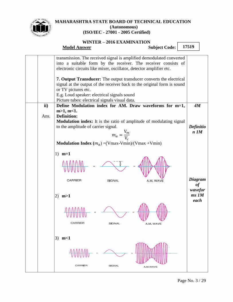
Draw and explain the block diagram of communication system.
Fig: block diagram of communication system
The main components of a basic communication system are:
1. Information or input signal
3x4=12
4M
2M
block
diagram

MAHARASHTRA STATE BOARD OF TECHNICAL EDUCATION
(Autonomous)
(ISO/IEC - 27001 - 2005 Certified)
WINTER – 2016 EXAMINATION
Model Answer Subject Code:
Page No. 2 / 29
17519
2. Input transducer
3. Transmitter
4. Communication channel or medium
5. Noise
6. Receiver
7. Output transducer
1. Information or input signal: The information can be in the form
of a sound signal like speech or music or it can be in the form of
pictures (T. V. signals) or it can be data information coming from a
computer.
2. Input Transducer: The communication system transmits
information in the form of electrical signals. The transducers convert
the non-electrical energy into its electrical energy called signals.
E.g. During a telephone conversation the words are in the form of
sound energy. The microphone converts sound signals into its
corresponding electrical signals.
TV camera converts the picture signals into electrical signals.
E.g. Microphone, TV, Camera.
3. Transmitter: It is used to convert the information into a signal
suitable for transmission over a given communication medium. It
increases the power level of the signal. The power level is increased
to cover a large range. The transmitter consists of electronic circuits
such as amplifier, mixer oscillator and power amplifier.
4. Communication channel or medium: The communication
channel is the medium used for transmission of electrical signals from
one place to other. The communication medium can be conducting
wires cables optical fiber or free space. Depending on the type of
communication medium two types of communication systems will
exist.
They are
1. Wire communication or line communication
2. Wireless communication or radio communication.
5. Noise: Noise is random undesirable electric energy that enters the
communication system through the communication medium and
interferes with the transmitted signal.
6. Receiver: The reception is exactly the opposite process of
2M
explanat
ion
MAHARASHTRA STATE BOARD OF TECHNICAL EDUCATION
(Autonomous)
(ISO/IEC - 27001 - 2005 Certified)
WINTER – 2016 EXAMINATION
Model Answer Subject Code:
Page No. 3 / 29
17519
transmission. The received signal is amplified demodulated converted
into a suitable form by the receiver. The receiver consists of
electronic circuits like mixer, oscillator, detector amplifier etc.
7. Output Transducer: The output transducer converts the electrical
signal at the output of the receiver back to the original form is sound
or TV pictures etc.
E.g. Loud speaker: electrical signals sound
Picture tubes: electrical signals visual data.
ii)
Ans.
Define Modulation index for AM. Draw waveforms for m=1,
m>1, m<1.
Definition:
Modulation index: It is the ratio of amplitude of modulating signal
to the amplitude of carrier signal.
Modulation Index ( ) =(Vmax-Vmin)/(Vmax +Vmin)
1) m=1
2) m>1
3) m<1
4M
Definitio
n 1M
Diagram
of
wavefor
ms 1M
each

MAHARASHTRA STATE BOARD OF TECHNICAL EDUCATION
(Autonomous)
(ISO/IEC - 27001 - 2005 Certified)
WINTER – 2016 EXAMINATION
Model Answer Subject Code:
Page No. 4 / 29
17519
iii)
Ans. Compare between FSK and PSK (any four points).
Parameter FSK PSK
Definition In this technique,
frequency of the RF
carrier is varied in
accordance with
baseband
digital input signal.
In this technique, phase
of the RF carrier is varied
in accordance with
baseband digital input
signal.
Band Width 4fb ( ) fb=bit frequency
fb
fb=bit frequency
Noise
immunity
High compared to
ASK
High compared to ASK
Waveforms
Bit rate Suitable upto 1200
bits/sec
Suitable upto 180 bits/sec
4M
Any
four
points
1M each
iv)
Ans. Explain the concept of frequency use in mobile communication.
Frequency reuse- Frequency reuse is the process in which the same
set of frequencies (channels) can be allocated to more than one cell.
Provided the cells are separated by sufficient distance reducing each
cells coverage area invites frequency reuse cells using the same set of
radio channels can avoid mutual interference, provided they are
properly separated. Each cell base station is allocated a group of
channel frequencies that are different from those of neighboring cells
& base station antennas are chosen to achieve a desired coverage
pattern within its cell. However as long as a coverage area is limited
to within a cells boundaries the same group of channel frequencies
4M
Relevant
diagram
2M
Concept
of
frequenc
y reuse
2M

MAHARASHTRA STATE BOARD OF TECHNICAL EDUCATION
(Autonomous)
(ISO/IEC - 27001 - 2005 Certified)
WINTER – 2016 EXAMINATION
Model Answer Subject Code:
Page No. 5 / 29
17519
may be used in different cells without interfacing with each other
provided the two cells are sufficient distance from one another.
1. b)
i)
Ans.
Attempt any one of the following:
Compare AM and FM on the basis of definition, waveform, noise
immunity, bandwidth, modulation index and frequencies used for
for transmission.
Compare AM FM
Definition Amplitude modulation
(AM) is the process of
changing the amplitude
of a high frequency
carrier signal in
proportion with
the instantaneous value
of the modulating signal
keeping frequency
&Phase constant.
Frequency modulation
(FM) is the process of
changing the frequency
of carrier signal in
proportion with the
instantaneous value of
the modulating signal
keeping Amplitude
&Phase constant.
Waveform AM wave:
FM wave:
Noise
immunity
Less More
Bandwidth BW= 2fm(fm -frequency
of modulating signal) Bandwidth =2 [ ] (fm - frequency of
modulating signal)
Modulatio
n index
Vm - Amplitude of
modulating signal
Vc- Amplitude of carrier
signal
fm - frequency of
modulating signal
Frequenci
es used for
transmissi
on
535 – 1605 KHz 88.1 – 108.1 MHz
1x6=6
6M
1M each
MAHARASHTRA STATE BOARD OF TECHNICAL EDUCATION
(Autonomous)
(ISO/IEC - 27001 - 2005 Certified)
WINTER – 2016 EXAMINATION
Model Answer Subject Code:
Page No. 6 / 29
17519
ii)
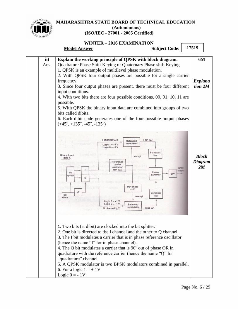
Ans. Explain the working principle of QPSK with block diagram.
Quadrature Phase Shift Keying or Quaternary Phase shift Keying
1. QPSK is an example of multilevel phase modulation.
2. With QPSK four output phases are possible for a single carrier
frequency.
3. Since four output phases are present, there must be four different
input conditions.
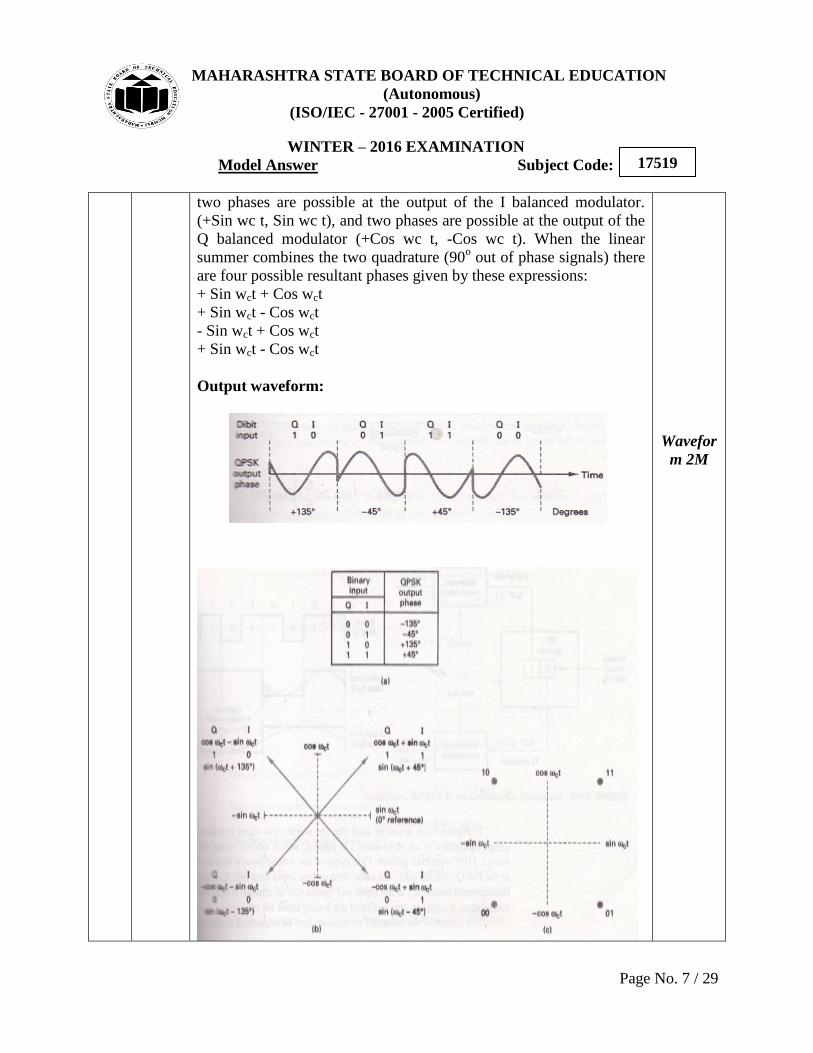
4. With two bits there are four possible conditions. 00, 01, 10, 11 are
possible.
5. With QPSK the binary input data are combined into groups of two
bits called dibits.
6. Each dibit code generates one of the four possible output phases
(+45o, +135
o, -45
o, -135
o)
1. Two bits (a, dibit) are clocked into the bit splitter.
2. One bit is directed to the I channel and the other to Q channel.
3. The I bit modulates a carrier that is in phase reference oscillator
(hence the name “I” for in phase channel).
4. The Q bit modulates a carrier that is 90o out of phase OR in
quadrature with the reference carrier (hence the name “Q” for
“quadrature” channel.
5. A QPSK modulator is two BPSK modulators combined in parallel.
6. For a logic 1 = + 1V
Logic 0 = - 1V
6M
Explana
tion 2M
Block
Diagram
2M
MAHARASHTRA STATE BOARD OF TECHNICAL EDUCATION
(Autonomous)
(ISO/IEC - 27001 - 2005 Certified)
WINTER – 2016 EXAMINATION
Model Answer Subject Code:
Page No. 7 / 29
17519
two phases are possible at the output of the I balanced modulator.
(+Sin wc t, Sin wc t), and two phases are possible at the output of the
Q balanced modulator (+Cos wc t, -Cos wc t). When the linear
summer combines the two quadrature (90o out of phase signals) there
are four possible resultant phases given by these expressions:
+ Sin wct + Cos wct
+ Sin wct - Cos wct
- Sin wct + Cos wct
+ Sin wct - Cos wct
Output waveform:
Wavefor
m 2M

MAHARASHTRA STATE BOARD OF TECHNICAL EDUCATION
(Autonomous)
(ISO/IEC - 27001 - 2005 Certified)
WINTER – 2016 EXAMINATION
Model Answer Subject Code:
Page No. 8 / 29
17519
2.
a)
Ans.
Attempt any four of the following:
Describe ionosphere wave propagation with the help of neat
sketch.
Electromagnetic waves that are directed above the horizon level are
called as sky waves. Typically, sky waves are radiated in a direction
that produces a relatively large angle with reference to earth. Sky
waves are radiated toward the sky, where they are either reflected or
refracted back to earth by the ionosphere. Because of this, sky wave
propagation is sometime called as ionosphere propagation. The
ionosphere is the region of space located approximately 50km to 400
km above Earth surface. The ionosphere is the upper portion of
earth‟s atmosphere. Therefore it absorbs large quantities of the sun
radiant energy, which ionizes the air molecules, creating free
electrons. When radio wave passes through the ionosphere the
electric field of the wave exerts a force on the free electrons, causing
them to vibrate. The vibrating electron decreases current, which is
equivalent to reducing the dielectric constant. Reducing the dielectric
constant increases the velocity of propagation and causes
electromagnetic waves to bend away from the regions of high
electron density toward regions of low electron density. As the wave
moves farther from earth ionization increase; however, there are
fewer air molecules to ionize. Therefore, the upper atmosphere has a
higher percentage of ionized molecules than the lower atmosphere.
The higher the ion density, the more refraction. Also because of the
ionosphere‟s non uniform composition and its temperature and
density variations, it is stratified. Essentially, three layers makeup the
ionosphere (the D, E, Flayers).
4x4=16
4M
Relevant
Diagram
2M
Relevant
Explana
tion 2M
MAHARASHTRA STATE BOARD OF TECHNICAL EDUCATION
(Autonomous)
(ISO/IEC - 27001 - 2005 Certified)
WINTER – 2016 EXAMINATION
Model Answer Subject Code:
Page No. 9 / 29
17519
b)
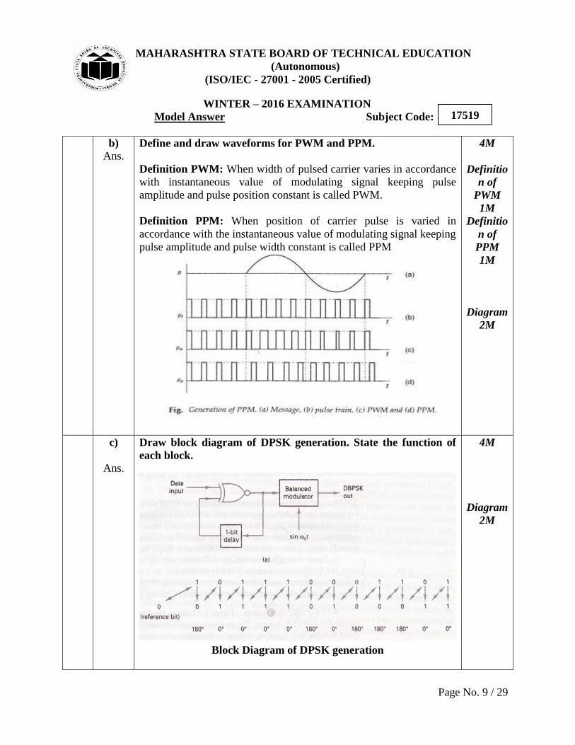
Ans. Define and draw waveforms for PWM and PPM.
Definition PWM: When width of pulsed carrier varies in accordance
with instantaneous value of modulating signal keeping pulse
amplitude and pulse position constant is called PWM.
Definition PPM: When position of carrier pulse is varied in
accordance with the instantaneous value of modulating signal keeping
pulse amplitude and pulse width constant is called PPM
4M
Definitio
n of
PWM
1M
Definitio
n of
PPM
1M
Diagram
2M
c)
Ans.
Draw block diagram of DPSK generation. State the function of
each block.
Block Diagram of DPSK generation
4M
Diagram
2M
MAHARASHTRA STATE BOARD OF TECHNICAL EDUCATION
(Autonomous)
(ISO/IEC - 27001 - 2005 Certified)
WINTER – 2016 EXAMINATION
Model Answer Subject Code:
Page No. 10 / 29
17519
Differential phase – shift keying (DPSK) is an alternative form of
digital modulation where the binary input information is contained in
the difference between two successive signaling elements rather than
the absolute phase.
XNOR: An incoming information bit is XNORed with the preceding
bit prior to entering the BPSK modulator (balanced modulator). For
the first data bit, there is no preceding bit with which to compare it.
Therefore, an initial reference bit is assumed. If the initial reference
bit is assumed a logic 1, the output from the XNOR circuit is simply
the complement of that bit.
Balanced Modulator: The first data bit is XNORed with the
reference bit. If they are the same, the XNOR output is a logic 1; if
they are different, the XNOR output is a logic 0. A logic 1 produces
+ sin at the output of the balanced modulator and a logic 0
produces- sin at the output.
Functio
ns 2M
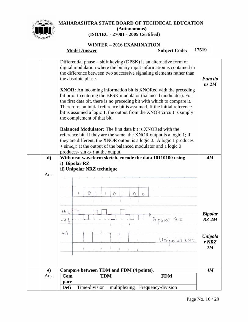
d)
Ans.
With neat waveform sketch, encode the data 10110100 using
i) Bipolar RZ
ii) Unipolar NRZ technique.
4M
Bipolar
RZ 2M
Unipola
r NRZ
2M
e)
Ans. Compare between TDM and FDM (4 points).
Com
pare
TDM FDM
Defi Time-division multiplexing Frequency-division
4M

MAHARASHTRA STATE BOARD OF TECHNICAL EDUCATION
(Autonomous)
(ISO/IEC - 27001 - 2005 Certified)
WINTER – 2016 EXAMINATION
Model Answer Subject Code:
Page No. 11 / 29
17519
nitio
n
(TDM) is digital technique to
combine data where time is
shared
multiplexing (FDM) is an
analog technique where
total range of frequncy is
divided into number of
frequency slots. Each slot of
frequency is allotted to each
channel
Sche
mati
c
Diag
ram
Prin
ciple Various channels of
different frequencies
combined, transmitted
through single wire &
separated at receiver with
help of demultiplexer.
Transmission time is
divided into number of
times slices.
Then each time slice is
allocated to different
source node, each of
which wants to send data.
Data flow of each
connection is divided into
units & link combines one
unit of each connection to
make a frame.
Data rate of link that
carries data from „n‟
connections must be „n‟
times data rate of a
connection to gurantee the
Various channels of
different frequencies
combined, transmitted
through single wire &
separated at receiver with
help of demultiplexer.
FDM is applied when
bandwidth of a link
greater than combined
bandwidth of signals to
be transmitted.
These modulated signals
are then combined into
single comosite signal
that can be transported
by the link.
Carrier frequencies are
separated by sufficient
bandwidth to
accommodate modulated
signal.
These bandwidth ranges
are channels through
1M each

MAHARASHTRA STATE BOARD OF TECHNICAL EDUCATION
(Autonomous)
(ISO/IEC - 27001 - 2005 Certified)
WINTER – 2016 EXAMINATION
Model Answer Subject Code:
Page No. 12 / 29
17519
flow of data. which various signals
travels.
Channels must be
separated by guard bands
to prevent signals from
overlapping.
Sync
hron
izati
on
Synchronitzation is required Synchronization is not
required
f)
Ans. Explain the concept of Hand-off.
Handoff: Cellular system has the ability to transfer calls that are
already in progress from one cell-site controller to another as the
mobile unit moves from cell to cell within the cellular network.
The transfer of a mobile unit from one base stations control to another
base stations control is called a handoff.
The process in which mobile station changes one cell to another,
hence from one base station to another base station and mobile station
remains connected to this called person is called “handoff” operation
of a base station.
As the vechicle containing the telephone passes through a cell it is
served by the cell transceiver.
The telephone call is routed through the MTSO and to the standard
telephone system.
As the vehicle moves the system automatically switches from one
cell to the next.
4M
Diagram
2M
Explana
tion 2M

MAHARASHTRA STATE BOARD OF TECHNICAL EDUCATION
(Autonomous)
(ISO/IEC - 27001 - 2005 Certified)
WINTER – 2016 EXAMINATION
Model Answer Subject Code:
Page No. 13 / 29
17519
The receiver in each cell station continously monitors the signal
strength of the mobile unit.
When the signal strength drops below a desired level, it
automatically seeks a cell where the signal ffrom the mobile ubit is
stronger.
The computer at the MTSO causes the transmission from the
vechicle to be switched from the weaker cell to the stronger cell. It
is called “Hand off” Mechanism.
Consider two co-channel cells using the frequencey F1 seperated by a
distance D. The radius R and the distance D are represented by q (co-
channel reuse ratio) q =D/R. The other frequency channels such as F2
F3 and F4 are selected between two co-channel cells to provide the
communication system in whole area . The corressponding cells are
C2, C3 and C4. Suppose a mobile unit is starting a cell in cell C1 and
then moves to C2. The call be dropped and reinitated in the
frequencey channel from F1 to F2 while mobile unit moves from cell
C1 to C2. The process of changing frequency can be done
automatically by the system without users mediation. This process is
called “Hand off”.
The process of reallocating a different voice channel to the mobile
cellular phonw as the user moves between cells during a call is called
Hand off.
3.
a)
Ans.
Attempt any four of the following:
Compare between DM and ADM (4 Points)
Parameters DM ADM
Number of bits per
sample
It uses only one bit
for one sample
Only one bit is used
to encode one
sample
Step size Step size is fixed Step size is variable
Distortions/errors Slop overload and
granular noise Granular noise
Signaling rate and
bandwidth
Low, if the input is
slow varying Lowest
Step size decision Up/Down counter Digital Processor
Feedback Feedback exists in
transmitter Feedback exists.
System Complexity Simple Simple
Noise immunity Very good Better than DM as it
has less errors
4x4=16
4M
Any
four
points
1M each
MAHARASHTRA STATE BOARD OF TECHNICAL EDUCATION
(Autonomous)
(ISO/IEC - 27001 - 2005 Certified)
WINTER – 2016 EXAMINATION
Model Answer Subject Code:
Page No. 14 / 29
17519
Dynamic range
Wide dynamic range
of Analog signal
cannot be present
Wide dynamic range
of Analog signal can
be used due to
variable step size
b)
Ans.
Calculate Bits per second of PCM system in which sampling
frequency is 8 KHz and each sample is converted into 8 bits with
A.D.C.
Given N=8, fs = 8 KHZ
Bit rate = N x fs = 8 x 8 KHZ
Baud rate=Bit rate = 64 K bit/sec (as transmission is binary)
4M
Analysis
/Given
Data =
1M,
formula
= 1M,
calculati
on =2M
c)
Ans.
State the bandwidth requirement of
i) ASK ii) FSK iii) DPSK iv) QPSK
Fb = input bit rate, ∆F = frequency duration
i) ASK= Fb
ii) FSK= 2(∆F + 2 Fb)
iii) DPSK= Fb
iv) QPSK = Fb/2
4M
Bandwid
th
require
ment
1M each
d)
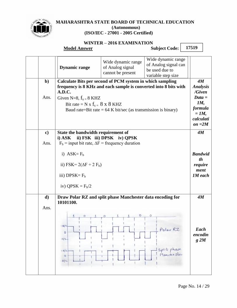
Ans.
Draw Polar RZ and split phase Manchester data encoding for
10101100.
4M
Each
encodin
g 2M
MAHARASHTRA STATE BOARD OF TECHNICAL EDUCATION
(Autonomous)
(ISO/IEC - 27001 - 2005 Certified)
WINTER – 2016 EXAMINATION
Model Answer Subject Code:
Page No. 15 / 29
17519
e)
Ans.
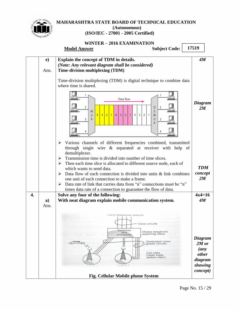
Explain the concept of TDM in details.
(Note: Any relevant diagram shall be considered)
Time-division multiplexing (TDM)
Time-division multiplexing (TDM) is digital technique to combine data
where time is shared.
Various channels of different frequencies combined, transmitted
through single wire & separated at receiver with help of
demultiplexer.
Transmission time is divided into number of time slices.
Then each time slice is allocated to different source node, each of
which wants to send data.
Data flow of each connection is divided into units & link combines
one unit of each connection to make a frame.
Data rate of link that carries data from “n” connections must be “n”
times data rate of a connection to guarantee the flow of data.
4M
Diagram
2M
TDM
concept
2M
4.
a)
Ans.
Solve any four of the following:
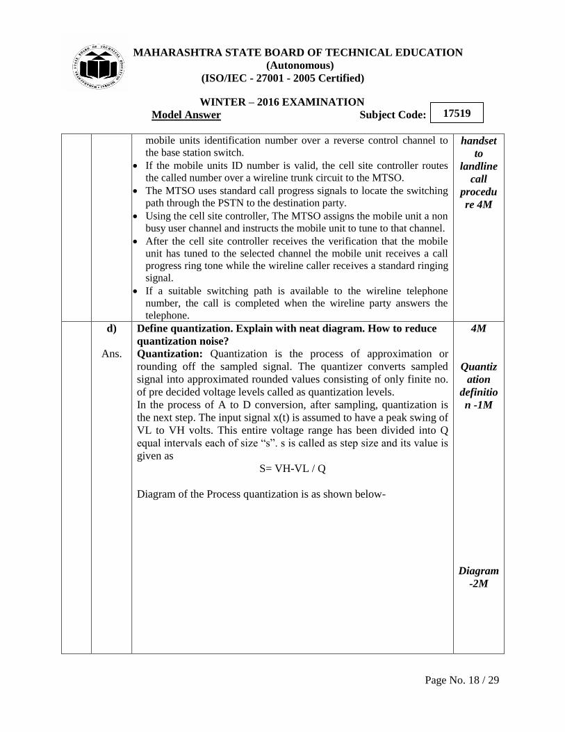
With neat diagram explain mobile communication system.
Fig. Cellular Mobile phone System
4x4=16
4M
Diagram
2M or
(any
other
diagram
showing
concept)

MAHARASHTRA STATE BOARD OF TECHNICAL EDUCATION
(Autonomous)
(ISO/IEC - 27001 - 2005 Certified)
WINTER – 2016 EXAMINATION
Model Answer Subject Code:
Page No. 16 / 29
17519
Figure above shows a cellular mobile phone system which consists of
Mobile Station (MS)
Base Station (BS), and
Mobile Telephone Switching Office (MTSO)
1) Mobile Station (MS): The mobile station contains a transceiver,
an antenna, and control circuitry and may be mounted in a vehicle or
used as a portable hand-held unit.
2) Base Station (BS): The base stations consist of several transmitter and receiver which
simultaneously handle full duplex communication and generally have
towers which support several transmitting frequency and receiving
antennas. The BS serves as a bridge between all mobile users and
connects simultaneous mobile calls via telephone lines or microwave
links to the MSC.
3) Mobile Telephone Switching Office (MTSO):
The MSC co-ordinates the activities of all the base stations and
connects the entire cellular system to the PSTN. A typical MTSO
handles 100,000 cellular subscribers and 5,000 simultaneous
conversations at a time, and accommodates all billing and system
maintenance functions as well. Communication between the BS and
mobiles is defined by a standard Common Air Interface (CAI) that
specifies four different channels.
4) Connections:
The radio and high-speed data links connected the three subsystems.
Each mobile unit can use only one channel at a time for its
communication link. Each site having multichannel capabilities that
can connect simultaneously to many mobile units.
Explana
tion 2M

MAHARASHTRA STATE BOARD OF TECHNICAL EDUCATION
(Autonomous)
(ISO/IEC - 27001 - 2005 Certified)
WINTER – 2016 EXAMINATION
Model Answer Subject Code:
Page No. 17 / 29
17519
b)
Ans.
Draw FSK waveform for the bit sequence 10101110.State the
advantages of FSK over ASK. State the disadvantages of FSK.
Advantages of FSK over ASK:
1. Low noise, since amplitude is constant
2. Power requirement is constant
3. Operates in virtually any wires available
4. High data rate
5. Used in long distance communication
6. Easy to decode
7. Good sensitivity
8. It has high security
9. Efficiency is high
Disadvantages of FSK:
1. The major disadvantage is its high bandwidth requirement.
2. Therefore FSK is extensively used in low speed modems having
bit rates below 1200 bits/sec.
3. The FSK is not preferred for the high speed modems because with
increase in speed, the bit rate increases.
4. This increases the channel bandwidth required to transmit the FSK
signal.
5. As the telephone lines have a very low bandwidth, it is not possible
to satisfy the bandwidth requirement of
FSK at higher speed. Therefore FSK is preferred only for the low
speed modems.
4M
Wavefor
m – 2M
Any 2
Advanta
ges- 1M
Any 2
Disadva
ntages-
1M
c)
Ans.
State the sequential steps for handset to landline call procedure.
(Note: Step wise marking can be considered)
The mobile subscriber enters the wireline telephone number into the
units memory using a standard touch-Tone keypad. The subscriber
then press a send key which transmits the called number as well as the
4M
Steps for
MAHARASHTRA STATE BOARD OF TECHNICAL EDUCATION
(Autonomous)
(ISO/IEC - 27001 - 2005 Certified)
WINTER – 2016 EXAMINATION
Model Answer Subject Code:
Page No. 18 / 29
17519
mobile units identification number over a reverse control channel to
the base station switch.
If the mobile units ID number is valid, the cell site controller routes
the called number over a wireline trunk circuit to the MTSO.
The MTSO uses standard call progress signals to locate the switching
path through the PSTN to the destination party.
Using the cell site controller, The MTSO assigns the mobile unit a non
busy user channel and instructs the mobile unit to tune to that channel.
After the cell site controller receives the verification that the mobile
unit has tuned to the selected channel the mobile unit receives a call
progress ring tone while the wireline caller receives a standard ringing
signal.
If a suitable switching path is available to the wireline telephone
number, the call is completed when the wireline party answers the
telephone.
handset
to
landline
call
procedu
re 4M
d)
Ans.
Define quantization. Explain with neat diagram. How to reduce
quantization noise?
Quantization: Quantization is the process of approximation or
rounding off the sampled signal. The quantizer converts sampled
signal into approximated rounded values consisting of only finite no.
of pre decided voltage levels called as quantization levels.
In the process of A to D conversion, after sampling, quantization is
the next step. The input signal x(t) is assumed to have a peak swing of
VL to VH volts. This entire voltage range has been divided into Q
equal intervals each of size “s”. s is called as step size and its value is
given as
S= VH-VL / Q
Diagram of the Process quantization is as shown below-
4M
Quantiz
ation
definitio
n -1M
Diagram
-2M

MAHARASHTRA STATE BOARD OF TECHNICAL EDUCATION
(Autonomous)
(ISO/IEC - 27001 - 2005 Certified)
WINTER – 2016 EXAMINATION
Model Answer Subject Code:
Page No. 19 / 29
17519
The quantization noise is shown by shaded portion of the above
waveform. The maximum value of quantization error ± s/2 where s is
a step size. Therefore to reduce quantization noise we have to reduce
step size by increasing the number of quantization levels i.e. Q.
Companding circuits can be used for reducing quantization error or
quantization noise. This reduces quantization noise without
increasing bandwidth. This is a process of artificially boosting low
amplitude signal during transmission and to reduce quantization error.
This is called compression. The reverse process of enhancing this
compressed signal (expansion) is carried out at the receiver to large
the signal back to original value.
Noise
reductio
n- 1M
e)
Ans. Explain Block diagram of satellite communication.
4M
Diagram
2M

MAHARASHTRA STATE BOARD OF TECHNICAL EDUCATION
(Autonomous)
(ISO/IEC - 27001 - 2005 Certified)
WINTER – 2016 EXAMINATION
Model Answer Subject Code:
Page No. 20 / 29
17519
A
satellite is any natural or artificial object located in space, capable of
receiving and retransmitting electromagnetic waves.
Transmitter
The satellite communication system consists of a satellite that links
many earth stations on the ground. When the user is connected to
earth station through a terrestrial network (telephone or leased line)
the user generates baseband s/g, processes & transmits to the satellite
at the earth station.
Satellite
It is a large repeater in space. It receives the modulated RF carrier in
uplink frequency spectrum from all the earth station in the network.
The frequency used for transmission from earth station to space
(satellite) is called uplink frequency. The satellite amplifies this
carrier & retransmits them to the earth in the down link frequency
spectrum. The frequency used for transmission from space to earth
(satellite to earth station) is called down link frequency. The uplink &
downlink frequency are made different in order to avoid interference
of these s/g is space.
Descript
ion 2M

MAHARASHTRA STATE BOARD OF TECHNICAL EDUCATION
(Autonomous)
(ISO/IEC - 27001 - 2005 Certified)
WINTER – 2016 EXAMINATION
Model Answer Subject Code:
Page No. 21 / 29
17519
Receiver
The earth station receives s/g from satellite this s/g is processed to get
the original baseband s/g which is then send to the user through
terrestrial network.
f)
Ans. Draw multiplexing hierarchy in FDM.
Multiplexing hierarchy in FDM:
4M
Diagram
4M
5.
a)
Ans.
Solve any four of the following:
Explain Shannon’s theorem related to channel capacity.
The capacity of a channel with bandwidth B and additive Gaussian
band limited white noise is
C=B log2 (1+S/N) bits/sec
Where S & N are the average signal power and noise power
respectively at the output of channel
N= ηB (if the two sided power spectral density of the noise is η/2
watts/Hz)
B= channel bandwidth
4x4=16
4M
Stateme
nt 2M
Equatio
n 2M
b)
Ans. State advantages, disadvantages and application of PCM.
Advantages –
1. High noise immunity.
2. Due to digital nature of signal, repeaters can be placed between
transmitter and receivers. The repeaters actually regenerate
received PCM signal. This is not possible in analog systems.
Repeaters further reduce effect of noise.
3. High transmitter efficiency.
4M
Any 2
advanta
ges 2M
MAHARASHTRA STATE BOARD OF TECHNICAL EDUCATION
(Autonomous)
(ISO/IEC - 27001 - 2005 Certified)
WINTER – 2016 EXAMINATION
Model Answer Subject Code:
Page No. 22 / 29
17519
4. It is possible to store PCM signal due to its digital nature.
5. It is possible to use various coding techniques so that only desired
person can decode received signal.
6. Good signal to noise ratio (SNR)
Disadvantages :
1. Encoding, decoding and quantizing circuit of PCM is very
complex.
2. Require large bandwidth compared to other systems
Applications:
1. In space communication where space craft transmits signal to
earth.
2. In telephony.
Any 1
disadvan
tage 1M
Any 1
applicati
on 1M
c)
Ans. State the applications of satellite communication systems(any 4)
1. The main application of satellite is communication. Satellites are
used as relay station in sky.
2. The main application of satellite is surveillance or observation.
E.g.:
a. Military satellites are used for reconnaissance.
b. Intelligence satellite collects information about enemies and
potential enemies.
c. Observation satellites are used as Metrological satellites and
weather satellites.
d. Satellites can spot diseased crop area mineral resources source of
pollution etc.
3. TV signals can be transmitted through satellites for redistribution.
4. Satellite can be used in navigation e.g. - Global positioning system
(GPS)
5. Telephone system uses satellites for long distance calls.
4M
Any 4
points
1M each
d)
Ans.
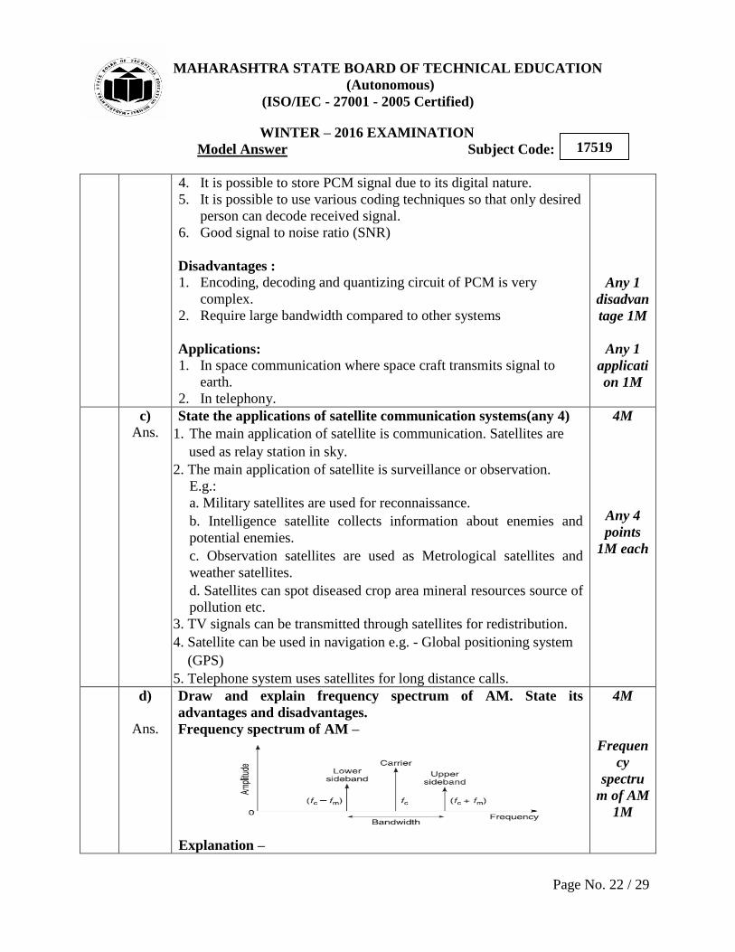
Draw and explain frequency spectrum of AM. State its
advantages and disadvantages.
Frequency spectrum of AM –
Explanation –
4M
Frequen
cy
spectru
m of AM
1M
MAHARASHTRA STATE BOARD OF TECHNICAL EDUCATION
(Autonomous)
(ISO/IEC - 27001 - 2005 Certified)
WINTER – 2016 EXAMINATION
Model Answer Subject Code:
Page No. 23 / 29
17519
1. AM wave consist of three frequency components namely carrier,
lower sideband and upper sideband.
2. Lower sideband is sinusoidal component which has frequency of
(fc-fm) and amplitude of (mEc/2)
3. Upper sideband is sinusoidal component which has frequency of
(fc+fm) and amplitude of (mEc/2)
4. Carrier has frequency fc and amplitude of Ec
Advantages –
1. AM transmitters are not complex.
2. AM receivers are simple and easy to detect.
3. Less expensive.
4. Covers large distance.
Disadvantages –
1. Requires large bandwidth.
2. Requires large power.
3. Get affected due to noise.
Explana
tion 1M
Any 1
advanta
ge 1M
Any 1
disadvan
tage 1M
e)
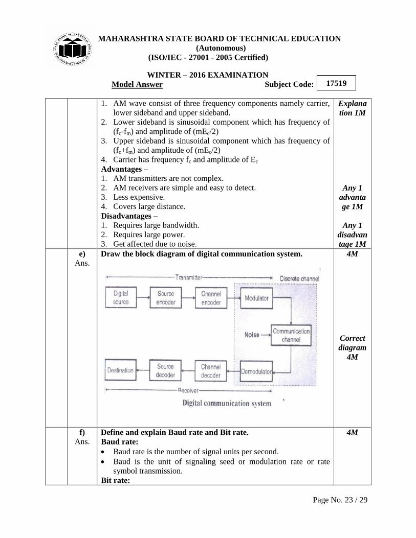
Ans. Draw the block diagram of digital communication system.
4M
Correct
diagram
4M
f)
Ans. Define and explain Baud rate and Bit rate.
Baud rate:
Baud rate is the number of signal units per second.
Baud is the unit of signaling seed or modulation rate or rate
symbol transmission.
Bit rate:
4M

MAHARASHTRA STATE BOARD OF TECHNICAL EDUCATION
(Autonomous)
(ISO/IEC - 27001 - 2005 Certified)
WINTER – 2016 EXAMINATION
Model Answer Subject Code:
Page No. 24 / 29
17519
Bit rate is the number of bits transmitted per second.
Data rate is also known as bit rate.
Bit rate = 1 /Bit interval
If the bit duration is Tb (known as bit interval), then bit rate will
be 1/Tb
Bit rate should be as high as possible.
With increase in data rate the bandwidth of transmission medium
must be increased in order to transmit the signal without any
distortion.
2M for
each
definitio
n and
explanat
ion
6. A)
i)
Ans.
Attempt Any ONE.
Draw the block diagram of AM super heterodyne AM Radio
Receiver. State the function of each block.
Function of block-
The AM signal transmitted by the transmitter travels through the air
and reaches the Receiving antenna. The signal is in the form of
electromagnetic waves. It induces a very small voltage into the
receiving antenna.
RF amplifier: The RF amplifier is used to select the wanted signal
and rejects the unwanted signals present at the antenna. It reduces the
effect of noise. At the output of RF amplifier we get the desired
signal at frequency fs.
Mixer: The mixer receives the signal from the RF amplifier at
frequency (fs) and from the local oscillator at frequency (f0) such that
f0>fs.
Intermediate frequency (IF): The mixer is a non-linear circuit. It
will mix the signals having frequency and to produce signals having
1x6=6
6M
Diagram
3M
Explana
tion 3M
MAHARASHTRA STATE BOARD OF TECHNICAL EDUCATION
(Autonomous)
(ISO/IEC - 27001 - 2005 Certified)
WINTER – 2016 EXAMINATION
Model Answer Subject Code:
Page No. 25 / 29
17519
frequencies fs, f0 , f0-fs , f0+ fs.
Out of these the difference of frequency component i.e. f0-fs is
selected and all other are rejected. This frequency is called
intermediate frequency (IF).
IF = f0-fs
Ganged Tuning: In order to maintain a constant difference between
the local oscillator frequency and the incoming signal frequency
ganged tuning is used, this is simultaneous tuning of RF amplifier
mixer and local oscillator. This is obtained by using ganged tuning
capacitors.
IF amplifier: The IF signal is amplifier by one or more IF amplifier
stage.
Detector: The amplifier IF signal is detected by the detection to
obtain the original modulating signal. Normally practical diode
detectors are used as detector.
Audio and Power Amplifier: The recovered modulating signal is
amplified to the adequate power level by using the Audio and Power
Amplifier and given to the Loudspeaker.
Loudspeaker converts the electrical signals into sound signals.
AGC (Automatic Gain Control): This circuit controls the gain of
RF and IF amplifiers to maintain a constant output voltage level even
when the signal level at the receiver input is fluctuating. This is done
by feeding a controlling D.C. voltage to the RF and IF amplifiers.
The amplitude of this dc voltage is proportional to the detector
output.
ii)
Ans.
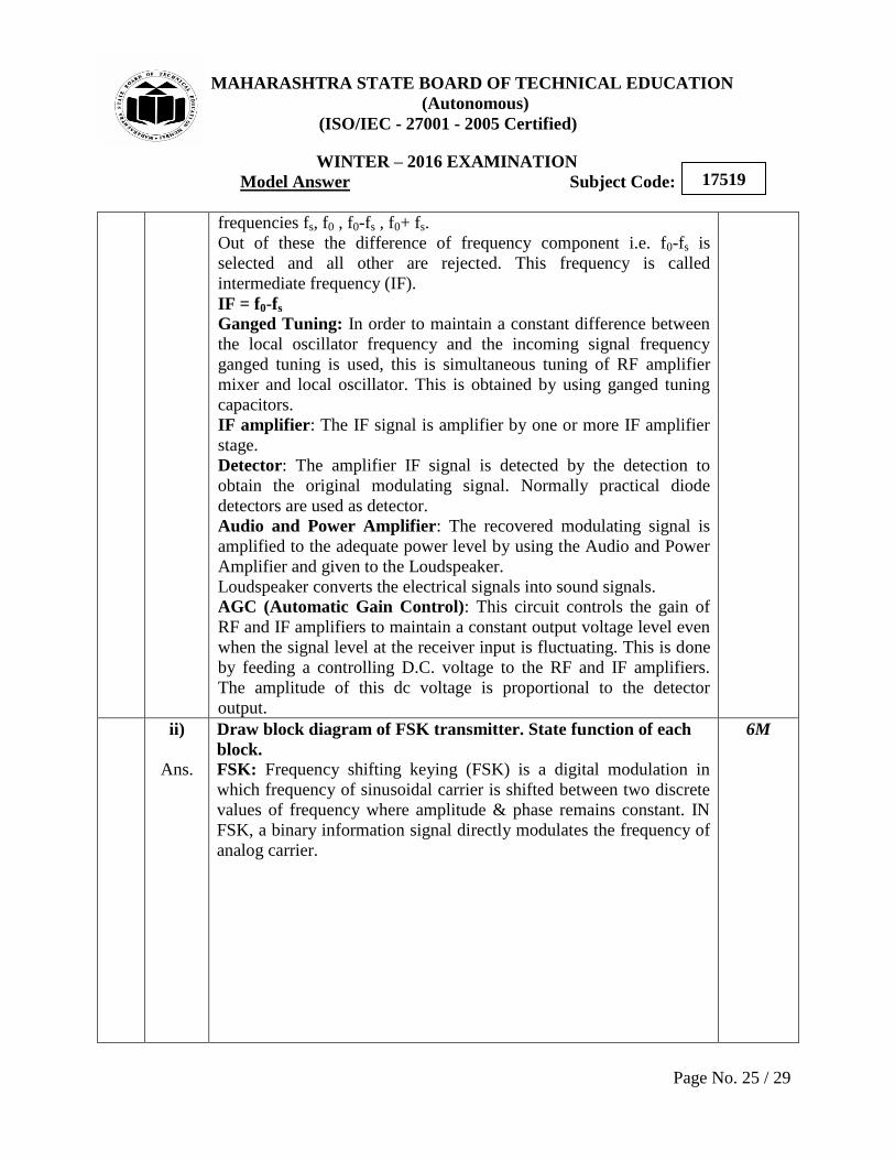
Draw block diagram of FSK transmitter. State function of each
block.
FSK: Frequency shifting keying (FSK) is a digital modulation in
which frequency of sinusoidal carrier is shifted between two discrete
values of frequency where amplitude & phase remains constant. IN
FSK, a binary information signal directly modulates the frequency of
analog carrier.
6M
MAHARASHTRA STATE BOARD OF TECHNICAL EDUCATION
(Autonomous)
(ISO/IEC - 27001 - 2005 Certified)
WINTER – 2016 EXAMINATION
Model Answer Subject Code:
Page No. 26 / 29
17519
Note that binary 1 corresponds to frequency 1270 Hz and binary 0 to
frequency 1070 Hz As shown in block diagram, Clock Oscillator:
Generates frequency of 271780Hz.
Divide ratio logic: Produces frequency division by 127
Frequency divider: when data input is zero, the frequency divider
output will be 1/127 of its input. Then output frequency will be 2140
Hz.
Flip Flop: this divides the 2140 Hz frequency by 2, producing the
desired 1070Hz output corresponding to binary “0‟ similarly, we get
1270 Hz frequency at binary “1‟ in which frequency divider will
divide 107.
Low pass filter: Removes higher frequency harmonics producing
sine wave output.
Diagram
3M
Explana
tion 3M
6. B)
i)
Ans.
Attempt any three.
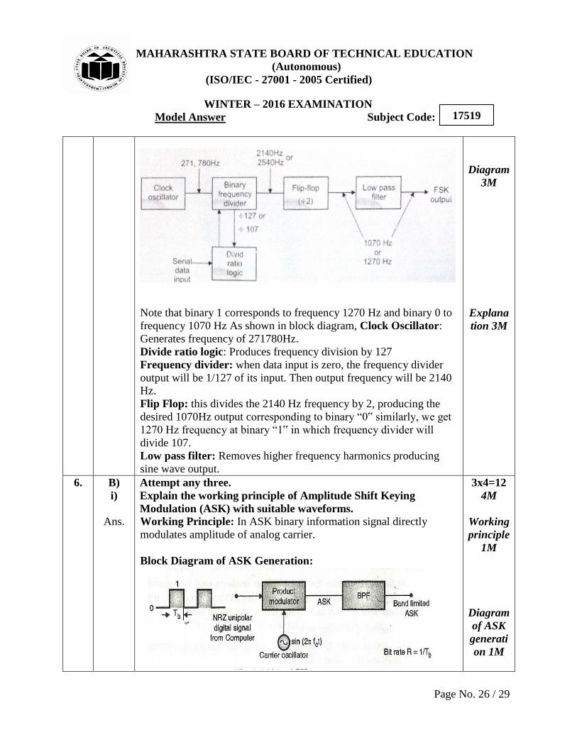
Explain the working principle of Amplitude Shift Keying
Modulation (ASK) with suitable waveforms.
Working Principle: In ASK binary information signal directly
modulates amplitude of analog carrier.
Block Diagram of ASK Generation:
3x4=12
4M
Working
principle
1M
Diagram
of ASK
generati
on 1M

MAHARASHTRA STATE BOARD OF TECHNICAL EDUCATION
(Autonomous)
(ISO/IEC - 27001 - 2005 Certified)
WINTER – 2016 EXAMINATION
Model Answer Subject Code:
Page No. 27 / 29
17519
Carrier Oscillator – Generates carrier i.e. sinewave of frequency fc
Digital Signal – Act as modulating or information signal.
Product Modulator – It is multiplier which multiplies modulating and
carrier signal. Due to multiplication ASK output will be present only
when binary „1‟ is to be transmitted.
BPF – Band pass filter allows only wanted frequency.
Waveform –
Explana
tion 1M
Wavefor
m 1M
ii)
Ans.
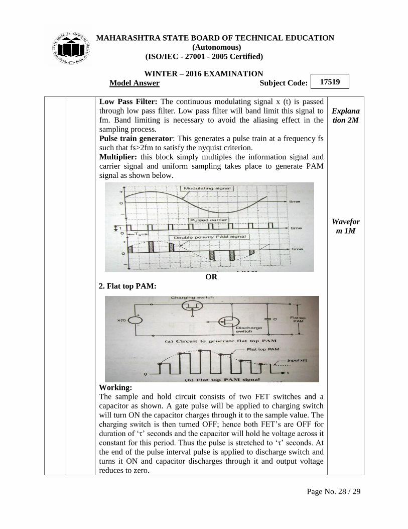
Draw diagram of PAM generation to obtain flat top sampling.
Explain the operation with suitable waveforms.
(Note: Any one of below mentioned or other relevant diagram may
also be considered)
In Pulse Amplitude Modulation system (PAM), the amplitude of the
pulsed carrier is changed in proportion with the instantaneous
amplitude of the modulating signal x(t). The carrier is in the form of
train of pulses.
1. Generation of PAM:
4M
Diagram
of PAM
1M
MAHARASHTRA STATE BOARD OF TECHNICAL EDUCATION
(Autonomous)
(ISO/IEC - 27001 - 2005 Certified)
WINTER – 2016 EXAMINATION
Model Answer Subject Code:
Page No. 28 / 29
17519
Low Pass Filter: The continuous modulating signal x (t) is passed
through low pass filter. Low pass filter will band limit this signal to
fm. Band limiting is necessary to avoid the aliasing effect in the
sampling process.
Pulse train generator: This generates a pulse train at a frequency fs
such that fs>2fm to satisfy the nyquist criterion.
Multiplier: this block simply multiples the information signal and
carrier signal and uniform sampling takes place to generate PAM
signal as shown below.
OR
2. Flat top PAM:
Working:
The sample and hold circuit consists of two FET switches and a
capacitor as shown. A gate pulse will be applied to charging switch
will turn ON the capacitor charges through it to the sample value. The
charging switch is then turned OFF; hence both FET‟s are OFF for
duration of „τ‟ seconds and the capacitor will hold he voltage across it
constant for this period. Thus the pulse is stretched to „τ‟ seconds. At
the end of the pulse interval pulse is applied to discharge switch and
turns it ON and capacitor discharges through it and output voltage
reduces to zero.
Explana
tion 2M
Wavefor
m 1M
MAHARASHTRA STATE BOARD OF TECHNICAL EDUCATION
(Autonomous)
(ISO/IEC - 27001 - 2005 Certified)
WINTER – 2016 EXAMINATION
Model Answer Subject Code:
Page No. 29 / 29
17519
iii)
Ans.
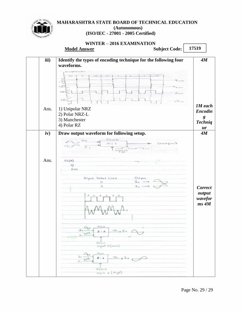
Identify the types of encoding technique for the following four
waveforms.
1) Unipolar NRZ
2) Polar NRZ-L
3) Manchester
4) Polar RZ
4M
1M each
Encodin
g
Techniq
ue
iv)
Ans.
Draw output waveform for following setup.
4M
Correct
output
wavefor
ms 4M