
MagPuck Technical Guide FINAL for OP (Fixed) - cascade … · RadioTransmission...
20
-
Upload
nguyennguyet -
Category
Documents
-
view
217 -
download
1
Transcript of MagPuck Technical Guide FINAL for OP (Fixed) - cascade … · RadioTransmission...


WARNING:SLEEVE SUSPENSION ONLY
THE MAGPUCKTM CAN ONLY BE USED WITHSLEEVE SUSPENSION.
USE OF INTERNAL SOCKET SEALING SYSTEMS(SEAL-IN LINERSTM, AURA SEALSTM, ETC.) WILL DAMAGE THE
MAGPUCKTM AND VOID THE WARRANTY.
Use the VaporPuckTM , ZeroPuck ODTM, ZeroPuck SPTM , AirPuckTM
for the following Liner Sealing systems: SEAL-IN TM LINERS, AURA / ECHO TM SOCKS SYMMETRY LINERSTM SECURE RINGTM
Table of ContentsSymbol Definitions ............................................................................3Warning and Safety Notices ..........................................................3Introduction .........................................................................................4
Unit Overview...................................................................................5Accessories ........................................................................................6
Installation ............................................................................................7Before Starting .................................................................................7Removal of the MagPuckTM ..........................................................9Patient Instructions .......................................................................10
Operating Instructions .................................................................12RunningVacuum Pump ..............................................................12Initial PumpWind Up ...................................................................12FindingMaximumVacuum Level .............................................13Shutdown Procedure ...................................................................13Automatic Pump Shut Off .........................................................13Operating Protocol ......................................................................13Charging ..........................................................................................14Hall Switch Operation .................................................................16
Maintenance / Cleaning ..............................................................17Environmental .................................................................................17
Environmental conditions of use including conditionsfor transport and storages 7.2.17
Tips andTricks ..................................................................................18Characteristics ...................................................................................18Electrical Specifications ...............................................................19Liner Configurations / Recommendations .........................19Sleeve Recommendations ..........................................................19WarrantyTerms /Return Policy ..................................................202

3
Symbol DefinitionsSymbol Description
Consult the Operating Instructions
Type B Applied Part
Direct Current
Alternating Current
Caution, Consult Instructions
Radio Transmission
Warnings And Safety NoticesREAD THESE INSTRUCTIONS FOR USE CAREFULLY AND PAYSPECIALATTENTIONTOALLSAFETY CONSIDERATIONSAND WARNINGS.
THIS MANUAL PROVIDES STEP-BY-STEP INSTRUCTIONSFOR SETUP AND OPERATIONS. FAILURE TO FOLLOW THESEINSTRUCTIONS CAN RESULT IN SERIOUS INJURY.
The MagPuckTMand its accompanying accessories donot contain any serviceable parts and should under nocircumstances be opened.
If the MagPuckTM or any of its accompanying accessoriesshow any signs of damage, they must not be used.
Do not immerse the MagPuckTM or any of its accompanyingaccessories in water or any other liquid.
Avoid all explosive/combustible materials while using theMagPuckTM System.
Battery Level of the MagPuckTM should be checkedperiodically to guarantee proper pressure levels.
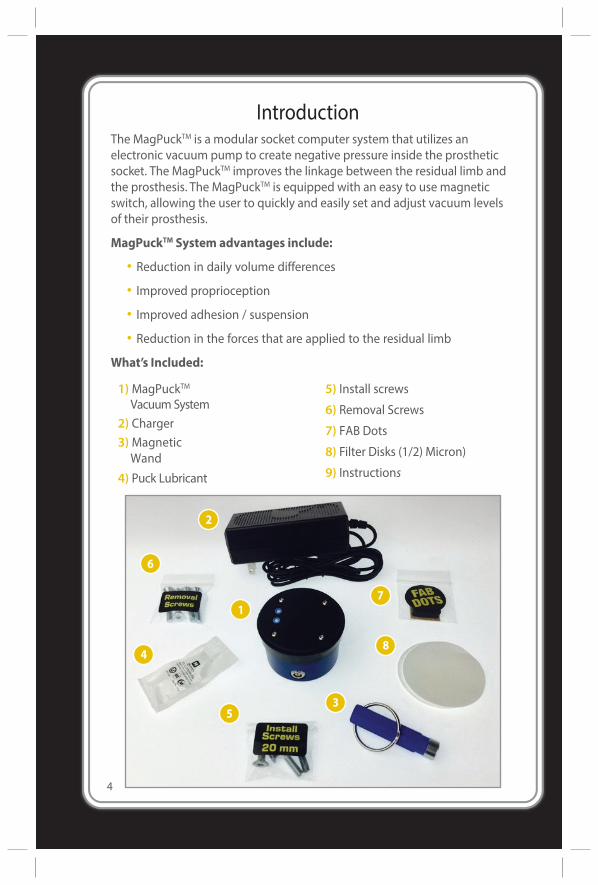
IntroductionThe MagPuckTM is a modular socket computer system that utilizes an electronic vacuum pump to create negative pressure inside the prosthetic socket. The MagPuckTM improves the linkage between the residual limb and the prosthesis. The MagPuckTM is equipped with an easy to use magnetic switch, allowing the user to quickly and easily set and adjust vacuum levels of their prosthesis.
MagPuckTM System advantages include:
• Reduction in daily volume differences
• Improved proprioception
• Improved adhesion / suspension
• Reduction in the forces that are applied to the residual limb
What’s Included:
1)MagPuckTM
Vacuum System2) Charger3)Magnetic
Wand4) Puck Lubricant
5) Install screws
6) Removal Screws
7) FAB Dots
8) Filter Disks (1/2) Micron)
9) Instructions
4
Unit OverviewThe MagPuckTM System consists of the following key components:
· MagPuckTM
· Socket (in which the MagPuckTM is installed)
· Prosthetic Liner
· AirWick
· Sealing Sleeve
· Distal Pad or Flexible inner liner
NOTE: THE MAGPUCK™ SYSTEM CAN ONLY BE USED WITH SLEEVESUSPENSION. USE OF INTERNAL MECHANICAL SEALS SUCH AS SEAL-INTM LINERS AND SIMILAR SYSTEMS WILL DAMAGE THE MAGPUCK™AND VOID THE WARRANTY.
The MagPuckTM creates an elevated vacuum in the space between thesocket and the liner when the MagPuckTM is activated. The user canconfigure and activate the MagPuckTM through the use of an easy to usemagnetic switch, manually using the included Magnet.
CAUTION: The socket MUST be fabricated following theMagPuckTM socket fabrication technique. The use of othertechniques may cause health risks for the patient.
CAUTION: Attempting to modify or use the MagPuckTM
System in any other configuration other than its intendeduse may cause health risks for the patient.
5
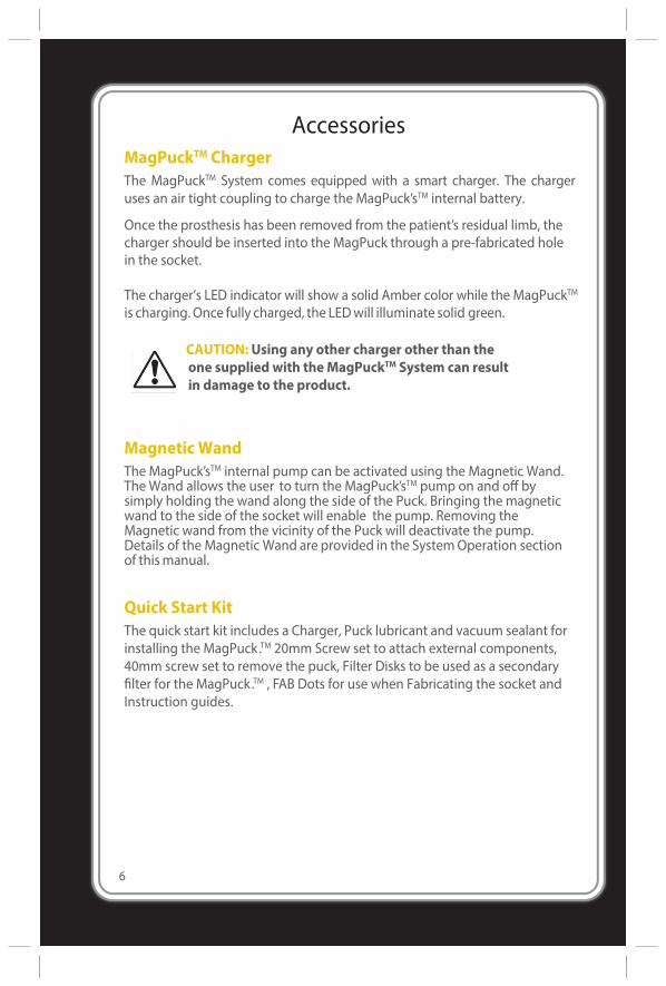
AccessoriesMagPuckTM ChargerThe MagPuckTM System comes equipped with a smart charger. The chargeruses an air tight coupling to charge the MagPuck’sTM internal battery.
Once the prosthesis has been removed from the patient’s residual limb, thecharger should be inserted into the MagPuck through a pre-fabricated holein the socket.
The charger’s LED indicator will show a solid Amber color while the MagPuckTM
is charging. Once fully charged, the LEDwill illuminate solid green.
CAUTION: Using any other charger other than theone supplied with the MagPuckTM System can resultin damage to the product.
Magnetic WandThe MagPuck’sTM internal pump can be activated using the Magnetic Wand. The Wand allows the user to turn the MagPuck’sTM pump on and off by simply holding the wand along the side of the Puck. Bringing the magnetic wand to the side of the socket will enable the pump. Removing the Magnetic wand from the vicinity of the Puck will deactivate the pump. Details of the Magnetic Wand are provided in the System Operation section of this manual.
Quick Start KitThe quick start kit includes a Charger, Puck lubricant and vacuum sealant forinstalling the MagPuck.TM 20mm Screw set to attach external components,40mm screw set to remove the puck, Filter Disks to be used as a secondaryfilter for the MagPuck.TM , FAB Dots for use when Fabricating the socket andInstruction guides.
6
7
Installation
WARNING: The user must be trained by the prosthetist orpractitioner who will be performing the product fitting.
WARNING: Installation of the MagPuckTM into thesocket must be done by a certified prosthetic technicianor practitioner who is fitting the user.
For clinical or technical assistance please contact 5280 Prosthetics LLC(Certified Prosthetists on staff) Information :5280 Prosthetics LLC 1501West Campus Drive, Suite J Littleton, CO 80120
1-800-460-0288 www.5280PROSTHETICS.COM
BEFORE STARTING:Ensure the bottom external surface of the socket is parallel to the interiorsurface on the distal end of the socket. Proper socket fabrication ensuresthat there are no shear forces on the installation screws.
INSTALLATION
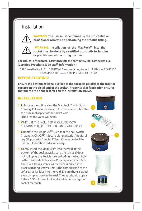
1) Lubricate the soft seal on the MagPuckTM with Dow Corning 111 Vacuum sealant. Also be sure to lubricate the proximal aspect of the socket void(The area the valve will seat).
2) ONLY USE THE INCLUDED PUCK LUBE (DOW CORNING 111) - OTHER LUBRICANTS WILL DRY OUT!
3) Orientate the MagPuckTM such that the hall switch (magnetic ON/OFF) is locate either anterior/medial LT leg OR posterior/medial RT Leg. Charge port will be medial. Orientation is discretionary.
4) Gently insert the MagPuckTM into the void at the bottom of the socket. Make sure the soft seal does not roll up as the Puck is inserted. Align the four hole pattern and side hole as the Puck is pulled into place. There will be resistance as the Puck is pulled into place with long screws. This is the compression of the soft seal as it slides into the void. Ensure there is good even compression on the seal. The seal should appear to be a 1/2”solid wet looking band (when using clear socket material).

8
5) Use a 4mm wrench to rotate the puck such that the four hole pattern is aligned with the four hole pattern in the bottom of the socket.
6) Use Screws to Pull the MagPuckTM into the bottom of the socket by connecting external hardware to the four hole pattern of the MagPuck.TM Start with longer(30 mm) screws and tighten opposite screws to pull the Puck down into the void evenly.
7) Replace the 30mm screws with the 20mm screws included with the MagPuckTM kit. Distal socket thickness should be 1/4". The MagPuckTM only accepts a screw depth of .63". If adding thicker alignable components adjust screw length accordingly.
8) CAREFULLY wipe out excess lube around the Puck Lid.
9) DO NOT GET LUBE ON THE WHITE AND BLUEINTAKE FILTERS...THIS WILL CLOG THE SYSTEM!
NOTE: Make sure the attachment componenthas a CENTER HOLE.
For best results: Use circular attachmentcomponents to reduce stress and better distributeforces to the bottom of the socket.
10) CRITICAL: Ensure the air exhaust hole is open to theambient air. This is where the MagPuckTM expulses the air. There should be a center hole drilled in the bottom of the socket. Use connection components that have a center hole. We use American Prosthetics TI-400BIL pyramid or Bull Dog.
11) Place the filter disk over the MagPuckTM lid. This 1/2 micron disk will protect the primaryintake of the the MagPuck. TM
The Filter disk should be placedfelt side down (facing puck lid).
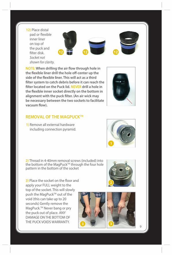
12) Place distalpad or flexibleinner lineron top ofthe puck andfilter disk.Socket notshown for clarity.
NOTE:When drilling the air flow through hole inthe flexible liner drill the hole off-center up theside of the flexible liner. This will act as a thirdfilter system to catch debris before it can reach thefilter located on the Puck lid. NEVER drill a hole inthe flexible inner socket directly on the bottom inalignment with the puck filter. (An air wick maybe necessary between the two sockets to facilitatevacuum flow).
REMOVAL OF THEMAGPUCKTM
1) Remove all external hardwareincluding connection pyramid.
2) Thread in 4-40mm removal screws (included) intothe bottom of theMagPuckTM through the four holepattern in the bottom of the socket
3) Place the socket on the floor andapply your FULL weight to thetop of the socket. This will slowlypush theMagPuckTM out of thevoid (this can take up to 20seconds) Gently remove theMagPuck.TM Never bang or prythe puck out of place. ANYDAMAGE ONTHE BOTTOMOFTHE PUCK VOIDSWARRANTY.
9
10
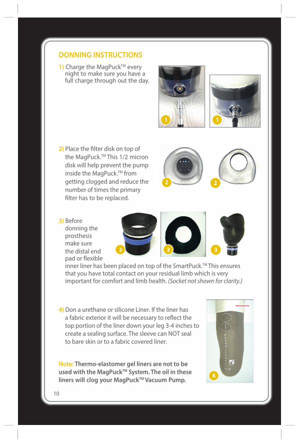
DONNING INSTRUCTIONS1) Charge the MagPuckTM every
night to make sure you have afull charge through out the day.
Note: Thermo-elastomer gel liners are not to beused with the MagPuckTM System.The oil in theseliners will clog your MagPuckTMVacuum Pump.
1
2) Place the filter disk on top ofthe MagPuck.TM This 1/2 microndisk will help prevent the pumpinside the MagPuck.TM fromgetting clogged and reduce thenumber of times the primaryfilter has to be replaced.
3) Beforedonning theprosthesismake surethe distal end 3pad or flexibleinner liner has been placed on top of the SmartPuck.TM This ensures that you have total contact on your residual limb which is very important for comfort and limb health. (Socket not shown for clarity.)
4) Don a urethane or silicone Liner. If the liner hasa fabric exterior it will be necessary to reflect thetop portion of the liner down your leg 3-4 inches tocreate a sealing surface. The sleeve can NOT sealto bare skin or to a fabric covered liner.
11
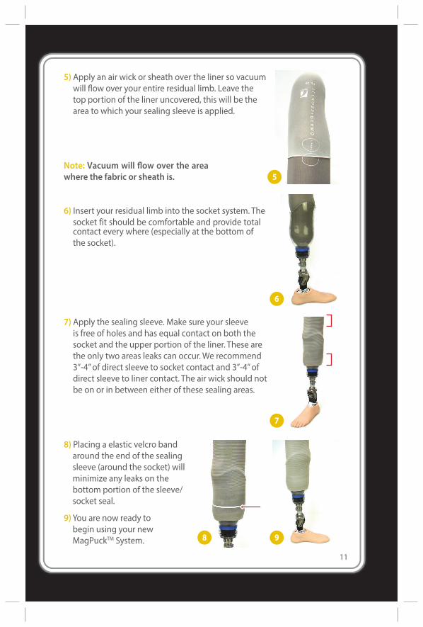
5) Apply an air wick or sheath over the liner so vacuumwill flow over your entire residual limb. Leave thetop portion of the liner uncovered, this will be thearea to which your sealing sleeve is applied.
Note: Vacuum will flow over the areawhere the fabric or sheath is.
6) Insert your residual limb into the socket system. Thesocket fit should be comfortable and provide totalcontact every where (especially at the bottom ofthe socket).
7) Apply the sealing sleeve. Make sure your sleeveis free of holes and has equal contact on both thesocket and the upper portion of the liner. These arethe only two areas leaks can occur.We recommend3”-4”of direct sleeve to socket contact and 3”-4”ofdirect sleeve to liner contact. The air wick should notbe on or in between either of these sealing areas.
8) Placing a elastic velcro bandaround the end of the sealingsleeve (around the socket) willminimize any leaks on thebottom portion of the sleeve/socket seal.
9)You are now ready tobegin using your newMagPuckTM System.
12
Operating InstructionsThe prosthesis should be applied at this stage and the sealing sleeve properly secured such that no air can enter the top of the system.
The MagPuckTM should be fully charged.
The MagPuckTM will not allow air to enter the bottom of the socket.
The ONLY place an air leak can occur is at the sleeve/socket linkage OR at the sleeve/Proximal liner linkage.
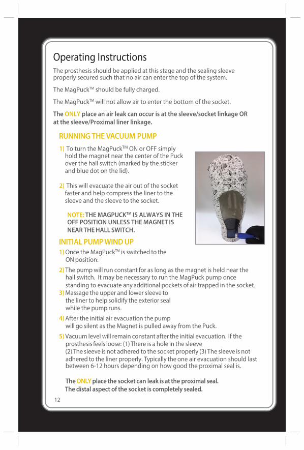
RUNNING THE VACUUM PUMP1) To turn the MagPuckTM ON or OFF simplyhold the magnet near the center of the Puckover the hall switch (marked by the stickerand blue dot on the lid).
2) This will evacuate the air out of the socketfaster and help compress the liner to thesleeve and the sleeve to the socket.
NOTE: THE MAGPUCKTM IS ALWAYS IN THEOFF POSITION UNLESS THEMAGNET ISNEARTHEHALLSWITCH.
INITIAL PUMPWINDUP1)Once theMagPuckTM is switched to the
ONposition:
2) The pumpwill run constant for as long as the magnet is held near thehall switch. It may be necessary to run the MagPuck pump oncestanding to evacuate any additional pockets of air trapped in the socket.
3)Massage the upper and lower sleeve tothe liner to help solidify the exterior sealwhile the pump runs.
4)After the initial air evacuation the pumpwill go silent as the Magnet is pulled away from the Puck.
5)Vacuum level will remain constant after the initial evacuation. If theprosthesis feels loose: (1) There is a hole in the sleeve(2) The sleeve is not adhered to the socket properly (3) The sleeve is notadhered to the liner properly. Typically the one air evacuation should lastbetween 6-12 hours depending on how good the proximal seal is.
TheONLYplace the socket can leak is at the proximal seal.The distal aspect of the socket is completely sealed.
13
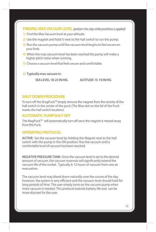
FINDINGMAXVACUUM LEVEL (performthis stepwhileprosthesis isapplied)1) Find theMaxVacuum level at your altitude.
2) Use the magnet and hold it next to the hall switch to run the pump.
3) Run the vacuumpumpuntil the vacuum level begins to feel secure onyour limb.
4) When themax vacuum level has been reached thepumpwill make ahigher pitch noise when running.
5) Choose avacuum level that feels secure andcomfortable.
6) Typicallymax vacuum is:
SEALEVEL 18-23 IN/HG ALTITUDE15-19 IN/HG
SHUT DOWN PROCEDURETo turn off the M agPuckTM simply remove the magnet from the vicinity of the hall switch in the center of the puck (The Blue dot on the lid of the Puck marks the hall switch location).
AUTOMATIC PUMPSHUT OFFThe MagPuckTM will automatically turn off once the magnet is moved away from the Puck.
OPERATING PROTOCOLACTIVE: Set the vacuum level by holding the Magnet next to the hall switch with the pump in the ON position. Run the vacuum until a comfortable level of vacuum has been reached.
NEGATIVE PRESSURE TANK: Once the vacuum level is set to the desired amount of vacuum, the vacuum reservoir will significantly extend the vacuum life of the socket. Typically 6-12 hours of vacuum from one air evacuation.
The vacuum level may bleed down naturally over the course of the day, however, the system is very efficient and the vacuum level should hold for long periods of time. The user simply turns on the vacuum pump when more vacuum is needed. This protocol extends battery life and can be more discreet for the user.
14
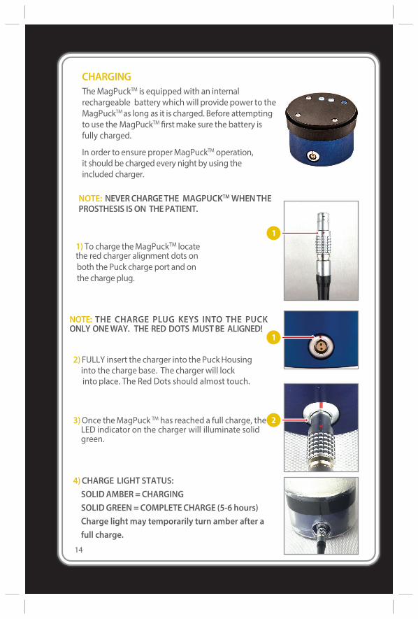
CHARGINGTheMagPuckTM is equippedwith an internalrechargeable battery whichwill provide power to theMagPuckTMas long as it is charged. Before attemptingto use the MagPuckTM firstmake sure the battery isfully charged.
In order to ensure properMagPuckTM operation,it should be charged every night by using theincluded charger.
1) To charge theMagPuckTM locatethe red charger alignment dots onboth the Puck charge port and onthe charge plug.
NOTE: NEVERCHARGETHE MAGPUCKTMWHENTHEPROSTHESIS ISON THEPATIENT.
2)FULLY insert the charger into the Puck Housing into the charge base. The charger will lock into place. The Red Dots should almost touch.
3)Once the MagPuck TM has reached a full charge, the LED indicator on the charger will illuminate solid green.
4)CHARGE LIGHT STATUS:SOLID AMBER = CHARGINGSOLID GREEN = COMPLETE CHARGE (5-6 hours) Charge light may temporarily turn amber after a full charge.
NOTE: THE CHARGE PLUG KEYS INTO THE PUCKONLY ONEWAY. THE RED DOTS MUSTBE ALIGNED!
15
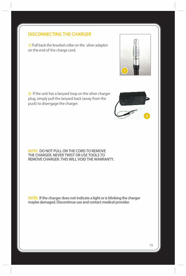
1) Pull back the knurled collar on the silver adaptoron the end of the charge cord.
2) If the unit has a lanyard loop on the silver chargerplug, simply pull the lanyard back (away from thepuck) to disengage the charger.
NOTE: DONOTPULLONTHECORDTOREMOVETHECHARGER. NEVER TWISTORUSE TOOLS TOREMOVECHARGER. THISWILL VOID THEWARRANTY.
NOTE: If the charger does not indicate a lightor is blinking the chargermaybedamaged.Discontinueuseandcontactmedical provider.
DISCONNECTING THE CHARGER
16
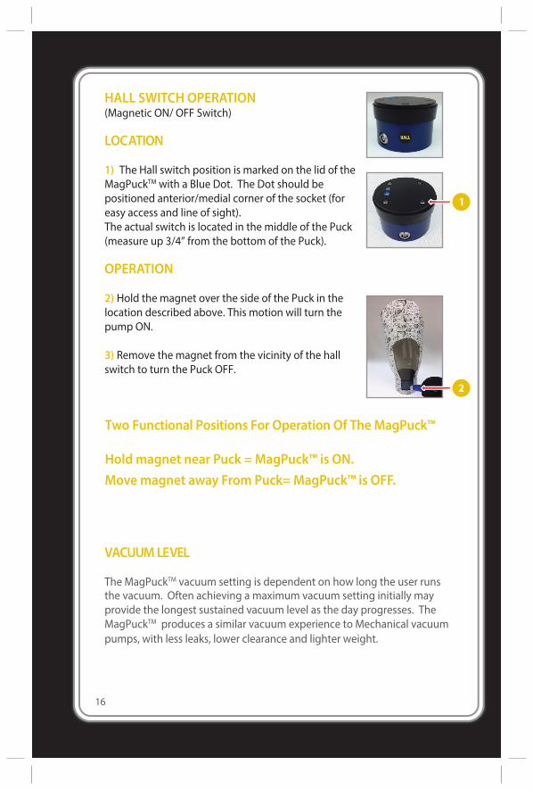
HALL SWITCH OPERATION(Magnetic ON/ OFF Switch)
LOCATION
1) The Hall switch position is marked on the lid of theMagPuckTM with a Blue Dot. The Dot should bepositioned anterior/medial corner of the socket (foreasy access and line of sight).The actual switch is located in the middle of the Puck(measure up 3/4” from the bottom of the Puck).
OPERATION
2) Hold the magnet over the side of the Puck in thelocation described above. This motion will turn thepump ON.
3) Remove the magnet from the vicinity of the hallswitch to turn the Puck OFF.
Two Functional Positions For Operation Of TheMagPuck™
Hold magnet near Puck = MagPuck™ is ON.Move magnet away From Puck= MagPuck™ is OFF.
VACUUMLEVEL
TheMagPuckTM vacuum setting is dependent on how long the user runsthe vacuum. Often achieving a maximum vacuum setting initially mayprovide the longest sustained vacuum level as the day progresses. TheMagPuckTM produces a similar vacuum experience to Mechanical vacuumpumps, with less leaks, lower clearance and lighter weight.
17
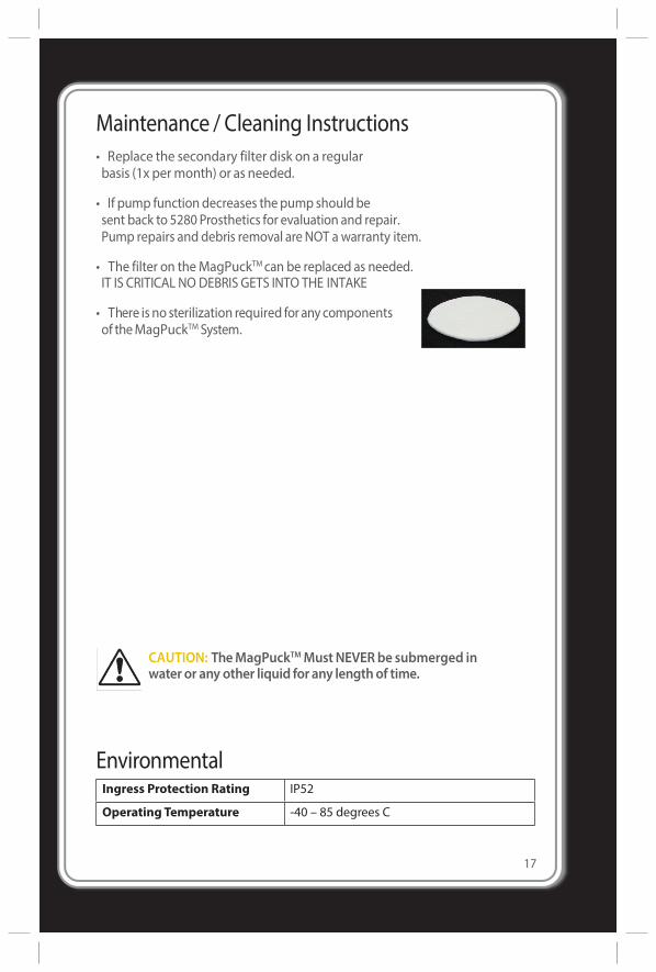
Maintenance / Cleaning Instructions• Replace the secondary filter disk on a regularbasis (1x permonth) or as needed.
• If pump function decreases thepump should besent back to 5280 Prosthetics for evaluation and repair.Pump repairs and debris removal are NOT awarranty item.
• The filter on theMagPuckTMcan be replaced as needed.IT IS CRITICAL NO DEBRIS GETS INTO THE INTAKE
• There is no sterilization required for any componentsof theMagPuckTM System.
CAUTION: TheMagPuckTMMustNEVER be submerged inwater or any other liquid for any lengthof time.
EnvironmentalIngress Protection Rating IP52
Operating Temperature -40 – 85 degrees C
18
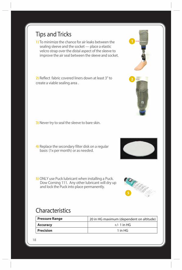
Tips and Tricks1) Tominimize the chance for air leaks between the
sealing sleeve and the socket—place a elasticvelcro strap over the distal aspect of the sleeve toimprove the air seal between the sleeve and socket.
2) Reflect fabric covered liners down at least 3" tocreate a viable sealing area .
3)Never try to seal the sleeve to bare skin.
4) Replace the secondary filter disk on a regularbasis (1xpermonth) or as needed.
5)ONLY use Puck lubricantwhen installing a Puck.Dow Corning 111. Any other lubricant will dry upand lock the Puck into place permanently.
CharacteristicsPressure Range 20 in HGmaximum (dependent on altitude)
Accuracy +/- 1 in HG
Precision 1 in HG
Electrical SpecificationsMagPuckTM
Operating Voltage 3.7VDC Typ.
Operating Current 20mAminimum 300mAmaximum
BatteryBattery Technology Rechargeable Lithium Polymer Battery
Battery Capacity 1000mAh
Battery Model
Time Between Charges 24 hours max
PowerStickTM
Input Voltage 100VAC minimum 240VAC maximum
Input Frequency 47Hz minimum 63Hz maximum
Input Current 0.6A maximum
Liner Configurations / RecommendationsMost liner configurations can be usedwith theMagPuckTM This includes:• Any silicone or urethane liner with an available sealing surface of 3”or more.(Used with a sealing sleeve configuration)• The Otto BockTM Anatomic 3D PURTM liner is a great polyurethane choice.Liner reflectionmethod (for use with fabric covered liners):We primarily useOssurTMDermo / Activa liners with a sleeve suspension. The liner is left longand the top half of the liner is reflected down such that the silicone facesoutward. The suspension sleeve is then rolled onto the reflected liner portion(at least 3”of sealing surface) to solidify the air seal.WeDONOT recommend thermo elastomer gel liners or any gel liner forvacuum systems.DONOTUSEANYTYPEOF INTERNALMECHANICAL SEAL LINER SUCHASSEAL-INTMORAURA SLEEVES TM
Sleeve RecommendationsThe general rule for sleeve selection is to choose sleeves that are tightand sticky.Rememberwe are trying to keep air molecules out of the socket this needs tobe an intimate fit!We recommend the following sleeves:• OssurTM Iceross Sleeve• ThermoPly Sleeves• OttoBock ProFlex Sleeve (must remove powder) 19
5280 PROSTHETICS, LLC1501WEST CAMPUS DRIVE, SUITE J | LITTLETON, CO 80120
1(800) 460-0288 | www.5280Prosthetics.com | www.Smartpuck.netCopyright ©2017 by 5280 Prosthetics, LLC • U S Patent 9,119,735 • Version 08/01/2017
Warranty Terms5280 Prosthetics, LLC warrants all of its products and services, to the original purchaser, to be free from defects in materials and workmanship. This warranty applies, subject to normal wear and tear, when the products are used as intended, without modifications, and following all of 5280 Prosthetics, LLC instructions and requirements.The duration of our Limited Warranties is 12 months effective from the date of receipt. 5280 Prosthetics, LLC’s sole obligation under this Limited Warranty shall be to repair, replace, or refund the cost of the item to the originalpurchaser, at 5280 Prosthetics’s sole discretion.This limited warranty does not cover : Clogged or obstructed electricpumps/pluming, damage due to accidents, pump failure due to inadequate filtration/pump maintenance, neglect, misuse, operation beyond capacity, use of internal mechanical seals, parts damaged by improper installation/removal, any alteration or repair by other that, in 5280 Prosthetics, LLC judgment, materially or adversely affects the product. Damage to the Puck from trying to pound or pry the Puck out of the socket (scratches, dents, evidence of tool use completely void the warranty of the device.)Use of this product is not a guarantee against injury. This Limited Warranty excludes liability for any personal injury, property damage, or special, incidental, or consequential damages arising out of, related, or incident to use the product, even if 5280 Prosthetics, LLC has been advised of the possibility of such potential loss or damage, unless state law otherwise precludes this exclusion.
Return PolicyPlease inspect all orders immediately upon receipt. In the event items wereordered or shipped in error, you must notify 5280 Prosthetics, LLC for a returnauthorization number. 5280 Prosthetics, LLC must be contacted within five (5) business days of the receipt of the items.No returns will be accepted without prior authorization. Due to the computerized nature of the MagPuckTM product and agreements with Apple IncTM the MagPuckTM can not be returned if the packaging has been opened. Please call 800-460-0288 to obtain a Return Authorization number.When returning a product for credit or replacement, please provide either the original or a copy of the invoice or packing slip.Credit or replacement of goods is subject to inspection and evaluation. 5280 Prosthetics, LLC will not issue a credit or replace any products returned to 5280 Prosthetics, LLC that are not in new or salable condition. The determination about whether returned products are new or salable will be made at 5280 Prosthetics, LLC sole discretion. Altered products are not returnable.
20