
3D Magnetostatic Analysis of Magneto-Inductive Devices for NDT
ARTICLE
Magnetostatic twists in room-temperatureskyrmions explored by nitrogen-vacancy centerspin texture reconstructionY. Dovzhenko1, F. Casola1,2, S. Schlotter 3,4, T.X. Zhou 1,3, F. Büttner 4, R.L. Walsworth1,2,
G.S.D. Beach 4 & A. Yacoby1
Magnetic skyrmions are two-dimensional non-collinear spin textures characterized by an
integer topological number. Room-temperature skyrmions were recently found in magnetic
multilayer stacks, where their stability was largely attributed to the interfacial
Dzyaloshinskii–Moriya interaction. The strength of this interaction and its role in stabilizing
the skyrmions is not yet well understood, and imaging of the full spin structure is needed to
address this question. Here, we use a nitrogen-vacancy centre in diamond to measure a map
of magnetic fields produced by a skyrmion in a magnetic multilayer under ambient conditions.
We compute the manifold of candidate spin structures and select the physically meaningful
solution. We find a Néel-type skyrmion whose chirality is not left-handed, contrary to pre-
ceding reports. We propose skyrmion tube-like structures whose chirality rotates through the
film thickness. We show that NV magnetometry, combined with our analysis method, pro-
vides a unique tool to investigate this previously inaccessible phenomenon.
DOI: 10.1038/s41467-018-05158-9 OPEN
1 Department of Physics, Harvard University, 17 Oxford Street, Cambridge, MA 02138, USA. 2 Harvard-Smithsonian Center for Astrophysics, 60 GardenStreet, Cambridge, MA 02138, USA. 3 John A. Paulson School of Engineering and Applied Sciences, Harvard University, Cambridge, MA 02138, USA.4Department of Materials Science and Engineering, Massachusetts Institute of Technology, Cambridge, MA 02139, USA. These authors contributed equally:Y. Dovzhenko, F. Casola. Correspondence and requests for materials should be addressed to A.Y. (email: [email protected])
NATURE COMMUNICATIONS | (2018) 9:2712 | DOI: 10.1038/s41467-018-05158-9 | www.nature.com/naturecommunications 1
1234
5678
90():,;
Magnetic skyrmions are topological defects originallyproposed as being responsible for the suppression oflong-range order in the two-dimensional (2D) Hei-
senberg model1,2 at finite temperature. The earliest observationsof magnetic skyrmions were reported in bulk crystals3 of non-centrosymmetric ferromagnetic materials at cryogenic tempera-tures. Recently, a new class of thin film materials has emerged,which support skyrmions at room temperature4–8. These resultshave paved the way towards spintronics applications and call for aquantitative and microscopic characterization of the novel spintextures. However, magnetic imaging of sputtered thin films atroom temperature in the presence of variable external magneticfields represents a serious experimental challenge for establishedtechniques8.
We address this challenge using a magnetic sensor based on asingle nitrogen-vacancy (NV) centre in diamond9. We record theprojection on the NV axis of the magnetic field produced by themagnetization pattern in the film. This information is sufficientfor reconstructing all three components of the magnetic fieldwithout the need for vector magnetometry10. However, obtainingthe underlying spin structure is an under-constrained problem11.System-dependent assumptions, e.g. regarding the spatial depen-dence of a certain spin component12, may artificially restrict themanifold of solutions compatible with experimental results.
We introduce a method to study such a manifold and show thatwe can classify all solutions by their helicity. We make use of anenergetic argument to require continuity of the structure and dis-card unphysical solutions. We discover a surprising type of structure
that disagrees with previous reports of Dzyaloshinskii–Moriyainteraction (DMI)13,14 in similar materials15–18.
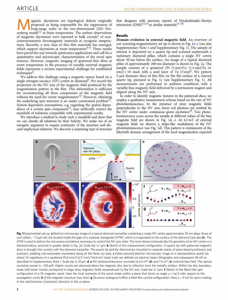
ResultsDomain evolution in external magnetic field. An overview ofour scanning magnetometry set-up is shown in Fig. 1a–c (see alsoSupplementary Note 1 and Supplementary Fig. 1). The sample ofinterest is deposited on a quartz tip and scanned underneath astationary diamond pillar, which contains a single NV centreabout 30 nm below the surface. An image of a typical diamondpillar of approximately 200 nm diameter is shown in Fig. 1a. Thesample consists of a sputtered [Pt (3 nm)/Co (1.1 nm)/Ta (4nm)] × 10 stack with a seed layer of Ta (3 nm)6. We pattern2-μm diameter discs of this film on the flat surface of a cleavedquartz tip, pictured in Fig. 1c (see Supplementary Fig. 1). Allmeasurements are performed in ambient conditions with avariable bias magnetic field delivered by a permanent magnet andaligned along the NV axis.
In order to identify magnetic features in the patterned discs, weemploy a qualitative measurement scheme based on the rate of NVphotoluminescence. In the presence of stray magnetic fieldsperpendicular to the NV axis, fewer red photons are emitted bythe NV centre under continuous green excitation19. Two photo-luminescence scans across the sample at different values of the biasmagnetic field are shown in Fig. 1d, e. At 6.5mT of externalmagnetic field, we observe a stripe-like modulation of the NVphotoluminescence (see Fig. 1d). This pattern is reminiscent of thelabyrinth domain arrangement of the local magnetization expected
∇ x mx,y = 0
f
b
4
4.5
5
5.5
6
× 105
Counts per second
B||,ext = 6.5 mT B||,ext = 7.5 mT
k
k || mx,yk x mx,y = 0x
y
z
k
k ⊥ mx,y
∇ · mx,y = 0 x
y
z
Diamondwith NV pillars
CPW
Quartztip
a c
ed
g
k · mx,y = 0
xyz
Fig. 1 Experimental set-up. a Electron microscopy image of a typical diamond nanopillar containing a single NV centre approximately 30 nm deep. Rows ofsuch pillars, ~ 1.5 μm tall, are located inside the gaps of a coplanar waveguide (CPW), which is evaporated on the surface of the diamond (see also b). TheCPW is used to deliver the microwave excitations necessary to control the NV spin state. The inset shows schematically the geometry of an NV centre in adiamond lattice, pictured in greater detail in Fig. 2d. Scale bar is 1 μm. b Sketch of the measurement configuration. A quartz tip with patterned magneticdiscs is brought into contact with the diamond nanopillar. The quartz tip and the diamond are mounted on separate stacks of piezo-based positioners andscanners, enabling sub-nanometre movement along all the three xyz axes. c False-coloured electron microscopic image of a representative quartz tip,where 10 repetitions of a sputtered Pt(3 nm)/Co(1.1 nm)/Ta(4 nm) stack (red) are defined via electron beam lithography and subsequent lift-off asdescribed in Supplementary Note 1. Scale bar is 10 μm. d, e NV photoluminescence recorded at 6.5 mT (d) and 7.5 mT (e) external bias field. The opticalexcitation power is ~ 100 μW. Higher counts are observed above the magnetic disc due to reflection from the metallic surface. Within the disc boundary,areas with lower counts correspond to large stray magnetic fields perpendicular to the NV axis. Scale bar is 1 μm. f Sketch of the Bloch-like spinconfiguration of a 1D magnetic spiral. Here the local moments of the spiral rotate within a plane that forms an angle γ= ±π/2 with respect to thepropagation vector k of the magnetic structure (see text). g Structure analogous to f for a Néel-like cycloid configuration. Here γ= 0 (π) for spins rotatingin the anticlockwise (clockwise) direction in the zx-plane
ARTICLE NATURE COMMUNICATIONS | DOI: 10.1038/s41467-018-05158-9
2 NATURE COMMUNICATIONS | (2018) 9:2712 | DOI: 10.1038/s41467-018-05158-9 | www.nature.com/naturecommunications
in these materials6,20. When the bias field is increased by 1mT, thelabyrinth domains collapse, forming a bubble-like feature shown inFig. 1e. Our aim in the present paper is to determine the form andnature (see Fig. 1f–g) of the associated spin texture in this high-fieldregime.
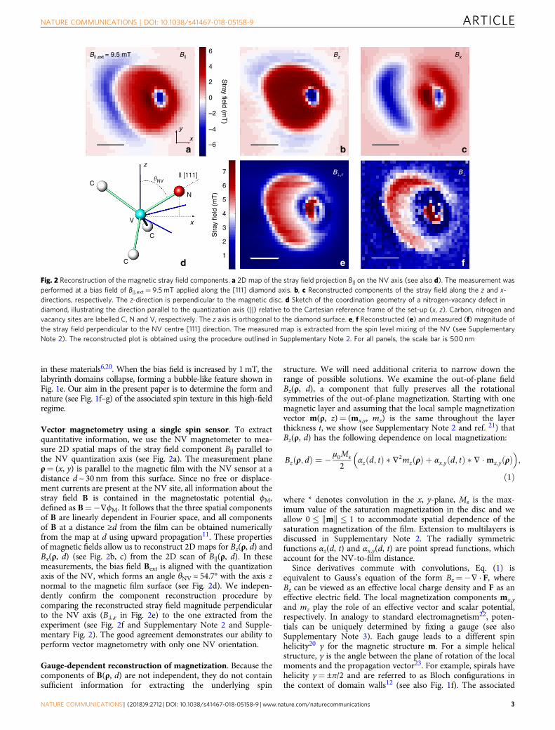
Vector magnetometry using a single spin sensor. To extractquantitative information, we use the NV magnetometer to mea-sure 2D spatial maps of the stray field component B|| parallel tothe NV quantization axis (see Fig. 2a). The measurement planeρ= (x, y) is parallel to the magnetic film with the NV sensor at adistance d ~ 30 nm from this surface. Since no free or displace-ment currents are present at the NV site, all information about thestray field B is contained in the magnetostatic potential ϕM,defined as B=−∇ϕM. It follows that the three spatial componentsof B are linearly dependent in Fourier space, and all componentsof B at a distance ≥d from the film can be obtained numericallyfrom the map at d using upward propagation11. These propertiesof magnetic fields allow us to reconstruct 2D maps for Bz(ρ, d) andBx(ρ, d) (see Fig. 2b, c) from the 2D scan of B||(ρ, d). In thesemeasurements, the bias field Bext is aligned with the quantizationaxis of the NV, which forms an angle θNV ≈ 54.7° with the axis znormal to the magnetic film surface (see Fig. 2d). We indepen-dently confirm the component reconstruction procedure bycomparing the reconstructed stray field magnitude perpendicularto the NV axis (B⊥,r in Fig. 2e) to the one extracted from theexperiment (see Fig. 2f and Supplementary Note 2 and Supple-mentary Fig. 2). The good agreement demonstrates our ability toperform vector magnetometry with only one NV orientation.
Gauge-dependent reconstruction of magnetization. Because thecomponents of B(ρ, d) are not independent, they do not containsufficient information for extracting the underlying spin
structure. We will need additional criteria to narrow down therange of possible solutions. We examine the out-of-plane fieldBz(ρ, d), a component that fully preserves all the rotationalsymmetries of the out-of-plane magnetization. Starting with onemagnetic layer and assuming that the local sample magnetizationvector m(ρ, z)= (mx,y, mz) is the same throughout the layerthickness t, we show (see Supplementary Note 2 and ref. 21) thatBz(ρ, d) has the following dependence on local magnetization:
Bzðρ; dÞ ¼ � μ0Ms
2αzðd; tÞ � ∇2mzðρÞ þ αx;yðd; tÞ � ∇ �mx;yðρÞ
� �;
ð1Þ
where * denotes convolution in the x, y-plane, Ms is the max-imum value of the saturation magnetization in the disc and weallow 0 � mk k � 1 to accommodate spatial dependence of thesaturation magnetization of the film. Extension to multilayers isdiscussed in Supplementary Note 2. The radially symmetricfunctions αz(d, t) and αx,y(d, t) are point spread functions, whichaccount for the NV-to-film distance.
Since derivatives commute with convolutions, Eq. (1) isequivalent to Gauss’s equation of the form Bz=−∇ · F, whereBz can be viewed as an effective local charge density and F as aneffective electric field. The local magnetization components mx,y
and mz play the role of an effective vector and scalar potential,respectively. In analogy to standard electromagnetism22, poten-tials can be uniquely determined by fixing a gauge (see alsoSupplementary Note 3). Each gauge leads to a different spinhelicity20 γ for the magnetic structure m. For a simple helicalstructure, γ is the angle between the plane of rotation of the localmoments and the propagation vector23. For example, spirals havehelicity γ= ±π/2 and are referred to as Bloch configurations inthe context of domain walls12 (see also Fig. 1f). The associated
B⊥,r B⊥|| [111]
V
C
C
C
z
x
�NV
N
a b c
d e f
x
y
Stray field (m
T)
B||,ext = 9.5 mT
Str
ay fi
eld
(mT
)
Bz BxB||
1
2
3
4
5
6
7
–6
–4
–2
0
2
4
6
Fig. 2 Reconstruction of the magnetic stray field components. a 2D map of the stray field projection B|| on the NV axis (see also d). The measurement wasperformed at a bias field of B||,ext= 9.5mT applied along the [111] diamond axis. b, c Reconstructed components of the stray field along the z and x-directions, respectively. The z-direction is perpendicular to the magnetic disc. d Sketch of the coordination geometry of a nitrogen-vacancy defect indiamond, illustrating the direction parallel to the quantization axis (||) relative to the Cartesian reference frame of the set-up (x, z). Carbon, nitrogen andvacancy sites are labelled C, N and V, respectively. The z axis is orthogonal to the diamond surface. e, f Reconstructed (e) and measured (f) magnitude ofthe stray field perpendicular to the NV centre [111] direction. The measured map is extracted from the spin level mixing of the NV (see SupplementaryNote 2). The reconstructed plot is obtained using the procedure outlined in Supplementary Note 2. For all panels, the scale bar is 500 nm
NATURE COMMUNICATIONS | DOI: 10.1038/s41467-018-05158-9 ARTICLE
NATURE COMMUNICATIONS | (2018) 9:2712 | DOI: 10.1038/s41467-018-05158-9 | www.nature.com/naturecommunications 3

condition k ·m= 0 for this case can be also expressed as∇ ·mx,y= 0, resembling the Coulomb gauge in electromagnet-ism22. The opposite case is a spin cycloid (see Fig. 1g) withhelicity γ= 0 (π) representing a Néel-like arrangement of spins12.In this case ∇ ×mx,y= 0. We show how to solve Eq. (1) for m inboth Bloch and Néel gauges in Supplementary Notes 3–5. Thisgauge approach allows us, for the first time, to systematicallyidentify the complete set of spin structures compatible with localmagnetometry data.
For both gauges, we use a numerical variational approach tofind a spin structure whose stray field matches the measured fieldmap. The measured field map is shown in Fig. 3a, while asimulated field map from a reconstructed spin structure is plottedin Fig. 3b. We plot cuts through the experimental map and thecomputed map along x and y axes in Fig. 3c. A 2D plot of the spinstructure for the Néel (Bloch) gauge is shown in Fig. 3d (Fig. 3e).In our analysis, we take into account local variations in thesaturation magnetization by scaling the magnetization vector m tothe mz value obtained in the saturated regime (see Fig. 3f,Supplementary Note 6 and Supplementary Figs. 3 and 4). The twostructures in Fig. 3d, e are particular examples chosen from aninfinite number of solutions to Eq. (1). These solutions are stablewith respect to variation in NV depth, as we demonstrate inSupplementary Note 6 and Supplementary Fig. 5, thus accountingfor the inherent uncertainty of NV implantation depth estimation.
A systematic study of the solution manifold requires a way tocontinuously tune γ from the Bloch to the Néel case. To vary thehelicity, we start by locally rotating the Bloch solution about the zaxis by an angle λ(ϕN− ϕB), where ϕN (ϕB) is the local azimuthalangle of the magnetic structure for the Néel (Bloch) configuration.
We then perform a rotation about an axis perpendicular to theresulting local moments so as to preserve its in-plane orientationand at the same time match the measured stray field (seeSupplementary Note 7). The parameter 0 ≤ λ ≤ 1 enables us tomove continuously through the manifold. We obtain an ensembleof quantitative, model-independent mz(ρ, λ) profiles for variousvalues of λ as shown in Fig. 4a.
Topology of the solutions. In order to select the best candidatetexture, we study the topology of the 2D vector field m(ρ, λ). Forany 2D normalized vector field n(ρ), the topological number Q isdefined as:
Q ¼ 14π
Zdxdyn � ∂n
∂x´∂n∂y
� �: ð2Þ
Whenever n || z at the boundary, any continuous solution n(ρ)must have an integer Q value24. Non-integer values of Q occur inthe case of a discontinuity, which is energetically costly andunstable24. Meanwhile, skyrmions are stable against local per-turbations because of the large energetic cost preventing theskyrmion (Q= 1) from folding back into the ferromagnetic state(Q= 0). We therefore introduce continuity as a criterion forselecting physically allowed solutions. In Fig. 4b, we plot theabsolute value of Q(λ) for each of the normalized vector fieldsn(ρ, λ), with n being the unit vector in the direction of m. Thenumber Q can be visualized as the number of times the spinconfiguration n wraps around the unit sphere25. To illustrate thevalue of Q, in the inset of Fig. 4b we plot the solid angle spannedby n while moving in the (x, y) plane. We obtain a value for Qapproaching −1 as λ → 1. We therefore identify Néel or nearly-
–0.6
0
0.6
1.2
1.8
2.4
3
3.6
−5−2.5
02.5
5
c
Bz (mT)
y
x
Str
ay fi
eld
Bz
(mT
)
a
xyData Simulated
b
x0
y0
x0, data
y0, datax0, rec.
y0, rec.
Msm
z (x
105 A
/m)
11.8 mT
9.5 mT
∇ · mx,y = 0∇ · mx,y = 0∇ x mx,y = 0
fd
mz 0
1
–1
0.5
–0.5
e
y0 cut
–6
–4
–2
0
2
4
6
Fig. 3 Extracting the local magnetic structure of the skyrmion. a z-component of the stray field from measured data at a bias field of B||,ext= 9.5mT appliedalong the [111] diamond axis. Since a single component of B contains all relevant information, Bz is chosen for comparison with simulations due to itsparticularly symmetric coupling to mz (see text). b Simulated map of Bz in both the Bloch and the Néel gauge. c Cuts along the x= x0 and y= y0 lines shownin b (solid lines) and comparison with experimental data in a (markers). d Magnetic structure obtained in the Néel gauge (see Supplementary Note 3). Itpreserves normalization of the local magnetization and produces a stray magnetic field that matches the experimental results. The colour map shows themz component. White arrows are proportional to the in-plane magnetization. The deviations of the skyrmion profile from a round shape are most likelyrelated to disc edge effects. e Plot similar to the one in d, obtained by choosing the Bloch gauge. The local magnetization at the centre of the skyrmion inthis case is mostly in-plane. f Comparison between the reconstructed Msmz local magnetization component in the Bloch gauge at two different bias fields(9.5 and 11.8 mT). The mz profile at saturation (11.8 mT) is used to normalize the local moments for the magnetic structure simulations shown in d, e (seeSupplementary Note 6). From this measurement, we obtain Msmz≃ 3.6 · 105 A/m at the disc centre (where mz= 1), which agrees with an independentlymeasured value of Msmz= 3.8 · 105 A/m. For all panels, the scale bar is 500 nm, except c where it is 400 nm
ARTICLE NATURE COMMUNICATIONS | DOI: 10.1038/s41467-018-05158-9
4 NATURE COMMUNICATIONS | (2018) 9:2712 | DOI: 10.1038/s41467-018-05158-9 | www.nature.com/naturecommunications
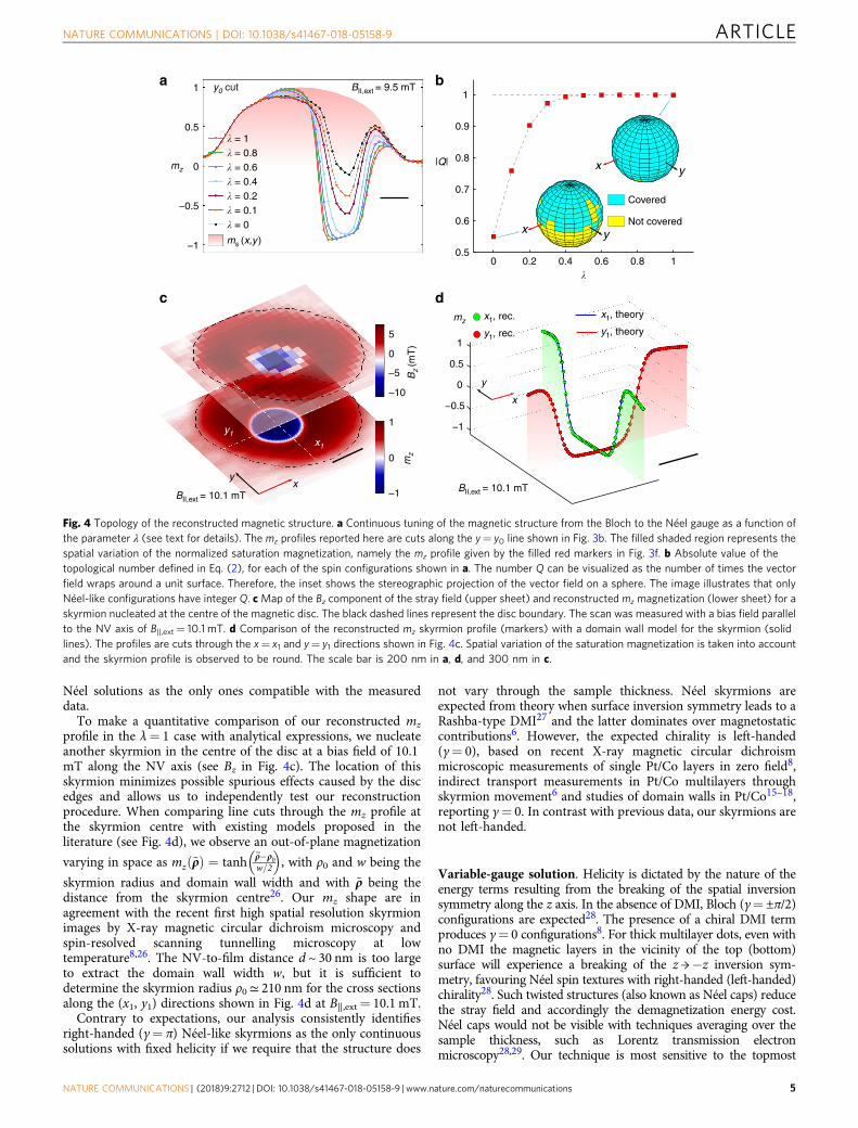
Néel solutions as the only ones compatible with the measureddata.
To make a quantitative comparison of our reconstructed mz
profile in the λ= 1 case with analytical expressions, we nucleateanother skyrmion in the centre of the disc at a bias field of 10.1mT along the NV axis (see Bz in Fig. 4c). The location of thisskyrmion minimizes possible spurious effects caused by the discedges and allows us to independently test our reconstructionprocedure. When comparing line cuts through the mz profile atthe skyrmion centre with existing models proposed in theliterature (see Fig. 4d), we observe an out-of-plane magnetization
varying in space as mzð~ρÞ ¼ tanh~ρ�ρ0w=2
� �, with ρ0 and w being the
skyrmion radius and domain wall width and with ~ρ being thedistance from the skyrmion centre26. Our mz shape are inagreement with the recent first high spatial resolution skyrmionimages by X-ray magnetic circular dichroism microscopy andspin-resolved scanning tunnelling microscopy at lowtemperature8,26. The NV-to-film distance d ~ 30 nm is too largeto extract the domain wall width w, but it is sufficient todetermine the skyrmion radius ρ0≃ 210 nm for the cross sectionsalong the (x1, y1) directions shown in Fig. 4d at B||,ext= 10.1 mT.
Contrary to expectations, our analysis consistently identifiesright-handed (γ= π) Néel-like skyrmions as the only continuoussolutions with fixed helicity if we require that the structure does
not vary through the sample thickness. Néel skyrmions areexpected from theory when surface inversion symmetry leads to aRashba-type DMI27 and the latter dominates over magnetostaticcontributions6. However, the expected chirality is left-handed(γ= 0), based on recent X-ray magnetic circular dichroismmicroscopic measurements of single Pt/Co layers in zero field8,indirect transport measurements in Pt/Co multilayers throughskyrmion movement6 and studies of domain walls in Pt/Co15–18,reporting γ= 0. In contrast with previous data, our skyrmions arenot left-handed.
Variable-gauge solution. Helicity is dictated by the nature of theenergy terms resulting from the breaking of the spatial inversionsymmetry along the z axis. In the absence of DMI, Bloch (γ= ±π/2)configurations are expected28. The presence of a chiral DMI termproduces γ= 0 configurations8. For thick multilayer dots, even withno DMI the magnetic layers in the vicinity of the top (bottom)surface will experience a breaking of the z→−z inversion sym-metry, favouring Néel spin textures with right-handed (left-handed)chirality28. Such twisted structures (also known as Néel caps) reducethe stray field and accordingly the demagnetization energy cost.Néel caps would not be visible with techniques averaging over thesample thickness, such as Lorentz transmission electronmicroscopy28,29. Our technique is most sensitive to the topmost
� = 0.8� = 0.6� = 0.4� = 0.2� = 0.1� = 0
−1
−0.5
0
0.5
1
0.8 10.60 0.40.20.5
0.6
0.7
0.8
0.9
1
x y
x y
Covered
Not covered
x
y
x1, theory
y1, theory
x1, rec.mz
y1, rec.
a
|Q|
b
c d
xy
mz
mz
ms (x,y )
y0 cut
y1x1
−1
−0.5
0
0.5
1
�
–10
–5
0
5
1
0
–1
Bz (m
T)
BII,ext = 10.1 mTBII,ext = 10.1 mT
BII,ext = 9.5 mT
� = 1
Fig. 4 Topology of the reconstructed magnetic structure. a Continuous tuning of the magnetic structure from the Bloch to the Néel gauge as a function ofthe parameter λ (see text for details). The mz profiles reported here are cuts along the y= y0 line shown in Fig. 3b. The filled shaded region represents thespatial variation of the normalized saturation magnetization, namely the mz profile given by the filled red markers in Fig. 3f. b Absolute value of thetopological number defined in Eq. (2), for each of the spin configurations shown in a. The number Q can be visualized as the number of times the vectorfield wraps around a unit surface. Therefore, the inset shows the stereographic projection of the vector field on a sphere. The image illustrates that onlyNéel-like configurations have integer Q. c Map of the Bz component of the stray field (upper sheet) and reconstructed mz magnetization (lower sheet) for askyrmion nucleated at the centre of the magnetic disc. The black dashed lines represent the disc boundary. The scan was measured with a bias field parallelto the NV axis of B||,ext= 10.1 mT. d Comparison of the reconstructed mz skyrmion profile (markers) with a domain wall model for the skyrmion (solidlines). The profiles are cuts through the x= x1 and y= y1 directions shown in Fig. 4c. Spatial variation of the saturation magnetization is taken into accountand the skyrmion profile is observed to be round. The scale bar is 200 nm in a, d, and 300 nm in c.
NATURE COMMUNICATIONS | DOI: 10.1038/s41467-018-05158-9 ARTICLE
NATURE COMMUNICATIONS | (2018) 9:2712 | DOI: 10.1038/s41467-018-05158-9 | www.nature.com/naturecommunications 5
layers, thus our observation of a right-handed skyrmion is the firstto indicate the presence of a Néel cap.
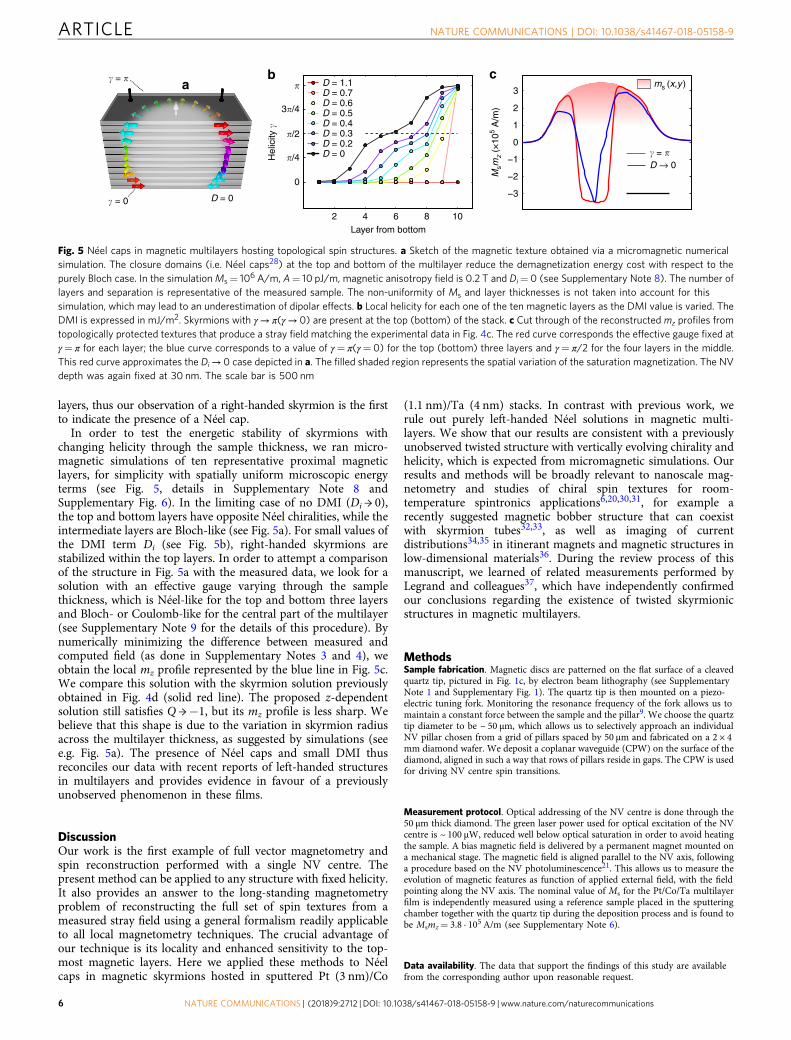
In order to test the energetic stability of skyrmions withchanging helicity through the sample thickness, we ran micro-magnetic simulations of ten representative proximal magneticlayers, for simplicity with spatially uniform microscopic energyterms (see Fig. 5, details in Supplementary Note 8 andSupplementary Fig. 6). In the limiting case of no DMI (Di → 0),the top and bottom layers have opposite Néel chiralities, while theintermediate layers are Bloch-like (see Fig. 5a). For small values ofthe DMI term Di (see Fig. 5b), right-handed skyrmions arestabilized within the top layers. In order to attempt a comparisonof the structure in Fig. 5a with the measured data, we look for asolution with an effective gauge varying through the samplethickness, which is Néel-like for the top and bottom three layersand Bloch- or Coulomb-like for the central part of the multilayer(see Supplementary Note 9 for the details of this procedure). Bynumerically minimizing the difference between measured andcomputed field (as done in Supplementary Notes 3 and 4), weobtain the local mz profile represented by the blue line in Fig. 5c.We compare this solution with the skyrmion solution previouslyobtained in Fig. 4d (solid red line). The proposed z-dependentsolution still satisfies Q →−1, but its mz profile is less sharp. Webelieve that this shape is due to the variation in skyrmion radiusacross the multilayer thickness, as suggested by simulations (seee.g. Fig. 5a). The presence of Néel caps and small DMI thusreconciles our data with recent reports of left-handed structuresin multilayers and provides evidence in favour of a previouslyunobserved phenomenon in these films.
DiscussionOur work is the first example of full vector magnetometry andspin reconstruction performed with a single NV centre. Thepresent method can be applied to any structure with fixed helicity.It also provides an answer to the long-standing magnetometryproblem of reconstructing the full set of spin textures from ameasured stray field using a general formalism readily applicableto all local magnetometry techniques. The crucial advantage ofour technique is its locality and enhanced sensitivity to the top-most magnetic layers. Here we applied these methods to Néelcaps in magnetic skyrmions hosted in sputtered Pt (3 nm)/Co
(1.1 nm)/Ta (4 nm) stacks. In contrast with previous work, werule out purely left-handed Néel solutions in magnetic multi-layers. We show that our results are consistent with a previouslyunobserved twisted structure with vertically evolving chirality andhelicity, which is expected from micromagnetic simulations. Ourresults and methods will be broadly relevant to nanoscale mag-netometry and studies of chiral spin textures for room-temperature spintronics applications6,20,30,31, for example arecently suggested magnetic bobber structure that can coexistwith skyrmion tubes32,33, as well as imaging of currentdistributions34,35 in itinerant magnets and magnetic structures inlow-dimensional materials36. During the review process of thismanuscript, we learned of related measurements performed byLegrand and colleagues37, which have independently confirmedour conclusions regarding the existence of twisted skyrmionicstructures in magnetic multilayers.
MethodsSample fabrication. Magnetic discs are patterned on the flat surface of a cleavedquartz tip, pictured in Fig. 1c, by electron beam lithography (see SupplementaryNote 1 and Supplementary Fig. 1). The quartz tip is then mounted on a piezo-electric tuning fork. Monitoring the resonance frequency of the fork allows us tomaintain a constant force between the sample and the pillar9. We choose the quartztip diameter to be ~ 50 μm, which allows us to selectively approach an individualNV pillar chosen from a grid of pillars spaced by 50 μm and fabricated on a 2 × 4mm diamond wafer. We deposit a coplanar waveguide (CPW) on the surface of thediamond, aligned in such a way that rows of pillars reside in gaps. The CPW is usedfor driving NV centre spin transitions.
Measurement protocol. Optical addressing of the NV centre is done through the50 μm thick diamond. The green laser power used for optical excitation of the NVcentre is ~ 100 μW, reduced well below optical saturation in order to avoid heatingthe sample. A bias magnetic field is delivered by a permanent magnet mounted ona mechanical stage. The magnetic field is aligned parallel to the NV axis, followinga procedure based on the NV photoluminescence21. This allows us to measure theevolution of magnetic features as function of applied external field, with the fieldpointing along the NV axis. The nominal value of Ms for the Pt/Co/Ta multilayerfilm is independently measured using a reference sample placed in the sputteringchamber together with the quartz tip during the deposition process and is found tobe Msmz= 3.8 · 105 A/m (see Supplementary Note 6).
Data availability. The data that support the findings of this study are availablefrom the corresponding author upon reasonable request.
�/4
�/2
3�/4
� D = 1.1D = 0.7 D = 0.6 D = 0.5D = 0.4 D = 0.3D = 0.2D = 0 H
elic
ity �
ba
2 4 6 8 10
0
� = �
� = 0 D = 0 −3
−2
−1
0
1
2
3
Layer from bottom
c
Msm
z (×
105 A
/m)
ms (x,y)
� = �D → 0
Fig. 5 Néel caps in magnetic multilayers hosting topological spin structures. a Sketch of the magnetic texture obtained via a micromagnetic numericalsimulation. The closure domains (i.e. Néel caps28) at the top and bottom of the multilayer reduce the demagnetization energy cost with respect to thepurely Bloch case. In the simulationMs= 106 A/m, A= 10 pJ/m, magnetic anisotropy field is 0.2 T and Di= 0 (see Supplementary Note 8). The number oflayers and separation is representative of the measured sample. The non-uniformity of Ms and layer thicknesses is not taken into account for thissimulation, which may lead to an underestimation of dipolar effects. b Local helicity for each one of the ten magnetic layers as the DMI value is varied. TheDMI is expressed in mJ/m2. Skyrmions with γ→ π(γ→ 0) are present at the top (bottom) of the stack. c Cut through of the reconstructed mz profiles fromtopologically protected textures that produce a stray field matching the experimental data in Fig. 4c. The red curve corresponds the effective gauge fixed atγ= π for each layer; the blue curve corresponds to a value of γ= π(γ= 0) for the top (bottom) three layers and γ= π/2 for the four layers in the middle.This red curve approximates the Di→ 0 case depicted in a. The filled shaded region represents the spatial variation of the saturation magnetization. The NVdepth was again fixed at 30 nm. The scale bar is 500 nm
ARTICLE NATURE COMMUNICATIONS | DOI: 10.1038/s41467-018-05158-9
6 NATURE COMMUNICATIONS | (2018) 9:2712 | DOI: 10.1038/s41467-018-05158-9 | www.nature.com/naturecommunications

Received: 12 December 2017 Accepted: 1 May 2018
References1. Belavin, Aa & Polyakov, A. M. Metastable states of two-dimensional isotropic
ferromagnets. Pisma Zh. Eksp. Teor. Fiz. 22, 503–506 (1975).2. Waldner, F. Are skyrmions (2D solitons) observable in 2D antiferromagnets?
J. Magn. Mater. 104, 793–794 (1992).3. Mühlbauer, S. et al. Skyrmion lattice in a chiral magnet. Science 323,
915–919 (2009).4. Wiesendanger, R. Nanoscale magnetic skyrmions in metallic films and
multilayers: a new twist for spintronics. Nat. Rev. Mater. 1, 16044 (2016).5. Rößler, U. K., Bogdanov, A. N. & Pfleiderer, C. Spontaneous skyrmion ground
states in magnetic metals. Nature 442, 797–801 (2006).6. Woo, S. et al. Observation of room-temperature magnetic skyrmions and their
current-driven dynamics in ultrathin metallic ferromagnets. Nat. Mater. 15,501–506 (2016).
7. Moreau-Luchaire, C. et al. Additive interfacial chiral interaction in multilayersfor stabilization of small individual skyrmions at room temperature. Nat.Nanotechnol. 11, 444–448 (2016).
8. Boulle, O. et al. Room-temperature chiral magnetic skyrmions in ultrathinmagnetic nanostructures. Nat. Nanotechnol. 11, 449–454 (2016).
9. Maletinsky, P. et al. A robust scanning diamond sensor for nanoscaleimaging with single nitrogen-vacancy centres. Nat. Nanotechnol. 7, 320–324(2012).
10. Lima, E. A. & Weiss, B. P. Obtaining vector magnetic field maps from single-component measurements of geological samples. J. Geophys. Res. 114, B06102(2009).
11. Blakely, R. J. Potential Theory in Gravity and Magnetic Applications(Cambridge University Press, Cambridge, 1996).
12. Tetienne, J.-P. et al. The nature of domain walls in ultrathin ferromagnetsrevealed by scanning nanomagnetometry. Nat. Commun. 6, 6733 (2015).
13. Dzyaloshinsky, I. A thermodynamic theory of ‘weak’ ferromagnetism ofantiferromagnetics. J. Phys. Chem. Solids 4, 241–255 (1958).
14. Moriya, T. Anisotropic superexchange interaction and weak ferromagnetism.Phys. Rev. 120, 91–98 (1960).
15. Belmeguenai, M. et al. Interfacial Dzyaloshinskii-Moriya interaction inperpendicularly magnetized Pt/Co/AlOx ultrathin films measured by Brillouinlight spectroscopy. Phys. Rev. B 91, 180405(R) (2015).
16. Emori, S., Bauer, U., Ahn, S.-M., Martinez, E. & Beach, G. S. D. Current-driven dynamics of chiral ferromagnetic domain walls. Nat. Mater. 12,611–616 (2013).
17. Pizzini, S. et al. Chirality-induced asymmetric magnetic nucleation in Pt/Co/AlOx ultrathin microstructures. Phys. Rev. Lett. 113, 047203 (2014).
18. Ryu, K.-S., Thomas, L., Yang, S.-H. & Parkin, S. Chiral spin torque at magneticdomain walls. Nat. Nanotechnol. 8, 527–533 (2013).
19. Tetienne, J.-P. et al. Magnetic-field-dependent photodynamics of single NVdefects in diamond: an application to qualitative all-optical magnetic imaging.New J. Phys. 14, 103033 (2012).
20. Nagaosa, N. & Tokura, Y. Topological properties and dynamics of magneticskyrmions. Nat. Nanotechnol. 8, 899–911 (2013).
21. Van der Sar, T., Casola, F., Walsworth, R. & Yacoby, A. Nanometre-scaleprobing of spin waves using single-electron spins. Nat. Commun. 6, 7886 (2015).
22. Griffiths, D. J. Introduction to Electrodynamics (Prentice Hall, Upper SaddleRiver, NJ, 1999).
23. Shibata, K. et al. Towards control of the size and helicity of skyrmions inhelimagnetic alloys by spin-orbit coupling. Nat. Nanotechnol. 8, 723–728 (2013).
24. Papanicolau, N. & Tomaras, T. N. Dynamics of magnetic vortices. Nucl. Phys.B 360, 425–462 (1991).
25. Altland, A. & Simons, B. D. Condensed Matter Field Theory (CambridgeUniversity Press, Cambridge, 2010).
26. Romming, N., Kubetzka, A., Hanneken, C., von Bergmann, K. &Wiesendanger, R. Field-dependent size and shape of single magneticskyrmions. Phys. Rev. Lett. 114, 177203 (2015).
27. Rowland, J., Banerjee, S. & Randeria, M. Skyrmions in chiral magnets withRashba and Dresselhaus spin-orbit coupling. Phys. Rev. B 93, 020404(R) (2016).
28. Montoya, S. A. et al. Tailoring magnetic energies to form dipole skyrmionsand skyrmion lattices. Phys. Rev. B 95, 024415 (2017).
29. Yu, X. Z. et al. Real-space observation of a two-dimensional skyrmion crystal.Nature 465, 901–904 (2010).
30. Fert, A., Cros, V. & Sampaio, J. Skyrmions on the track. Nat. Nanotechnol. 8,152–156 (2013).
31. Milde, P. et al. Unwinding of a skyrmion lattice by magnetic monopoles.Science 340, 1076–1080 (2013).
32. Rybakov, F. N., Borisov, A. B., Blügel, S. & Kiselev, N. S. New type of stableparticlelike states in chiral magnets. Phys. Rev. Lett. 115, 117201 (2015).
33. Zheng, F., et al. Experimental observation of chiral magnetic bobbers in B20-type FeGe. Nature Nanotechnol.13, 451–455 (2018).
34. Jiang, W. et al. Direct observation of the skyrmion Hall effect. Nat. Phys. 13,162–169 (2017).
35. Chang, K., Eichler, A., Rhensius, J., Lorenzelli, L. & Degen, C. L. Nanoscaleimaging of current density with a single-spin magnetometer. Nano Lett. 17,2367–2373 (2017).
36. Huang, B. et al. Layer-dependent ferromagnetism in a van der Waals crystaldown to the monolayer limit. Nature 546, 270–273 (2017).
37. Legrand, W. et al. Hybrid chiral domain walls and skyrmions in magneticmultilayers. Preprint at https://arxiv.org/pdf/1712.05978.pdf (2018).
AcknowledgementsThis work is supported by the Gordon and Betty Moore Foundations EPiQS Initiativethrough Grant GBMF4531. A.Y. and R.L.W. are also partly supported by the QuASARand the MURI QuISM projects. A.Y. is also partly supported by the Army ResearchOffice under Grant Number W911NF-17-1-0023. The views and conclusions containedin this document are those of the authors and should not be interpreted as representingthe official policies, either expressed or implied, of the Army Research Office or the U.S.Government. The U.S. Government is authorized to reproduce and distribute reprints forGovernment purposes notwithstanding any copyright notation herein. Work at MIT wassupported by the U.S. Department of Energy (DOE), Office of Science, Basic EnergySciences (BES) under Award no. DE-SC0012371 (sample fabrication and magneticproperties characterization). F.C. acknowledges support from the Swiss National ScienceFoundation (SNSF) grant no. P300P2-158417. S.S. acknowledges the National ScienceFoundation Graduate Research Fellowship under grant no. DGE1144152. F.B.acknowledges financial support by the German Research Foundation through grant no.BU 3297/1-1. Diamond samples were provided by Element Six (UK). We thank Dr. MarcWarner (Harvard) for helpful ideas in the initial stages of the experiment and Dr. RainerStöhr (Harvard–Stuttgart) for technical advice. We thank James Rowland (Ohio State)for fruitful discussions. This work was performed in part at the Center for NanoscaleSystems (CNS), a member of the National Nanotechnology Coordinated InfrastructureNetwork (NNCI), which is supported by the National Science Foundation under NSFaward no. 1541959. CNS is part of Harvard University.
Author contributionsY.D., F.C., S.S., G.S.D.B., and A.Y. conceived the experiment. T.Z. and F.C. designed anddeveloped the quartz tips and the diamond. T.Z. optimized the fabrication procedure. S.S.developed the deposition recipes and optimized the magnetic properties of the multi-layers. Y.D. and F.C. performed the experiment. F.C. developed the theoretical model. F.C. and Y.D. performed data analysis. R.L.W., G.S.D.B., and A.Y. provided guidance. F.B.and G.S.D.B proposed the twisted skyrmion model, and F.B. carried out the associatedsimulations. A.Y. supervised the work. All authors contributed to the writing and thecontent of the manuscript.
Additional informationSupplementary Information accompanies this paper at https://doi.org/10.1038/s41467-018-05158-9.
Competing interests: The authors declare no competing interests.
Reprints and permission information is available online at http://npg.nature.com/reprintsandpermissions/
Publisher's note: Springer Nature remains neutral with regard to jurisdictional claims inpublished maps and institutional affiliations.
Open Access This article is licensed under a Creative CommonsAttribution 4.0 International License, which permits use, sharing,
adaptation, distribution and reproduction in any medium or format, as long as you giveappropriate credit to the original author(s) and the source, provide a link to the CreativeCommons license, and indicate if changes were made. The images or other third partymaterial in this article are included in the article’s Creative Commons license, unlessindicated otherwise in a credit line to the material. If material is not included in thearticle’s Creative Commons license and your intended use is not permitted by statutoryregulation or exceeds the permitted use, you will need to obtain permission directly fromthe copyright holder. To view a copy of this license, visit http://creativecommons.org/licenses/by/4.0/.
© The Author(s) 2018
NATURE COMMUNICATIONS | DOI: 10.1038/s41467-018-05158-9 ARTICLE
NATURE COMMUNICATIONS | (2018) 9:2712 | DOI: 10.1038/s41467-018-05158-9 | www.nature.com/naturecommunications 7


![ALGEBRAIC TWISTS OF MODULAR FORMS AND HECKE ORBITS · GAFA ALGEBRAIC TWISTS OF MODULAR FORMS with R i,S i ∈ Z[X] coprime (in Q[X]), and given a non-trivial Dirichlet character χ(modp),](https://static.fdocuments.us/doc/165x107/5fcc3056b4765f09011ac431/algebraic-twists-of-modular-forms-and-hecke-orbits-gafa-algebraic-twists-of-modular.jpg)