Magnetisation of 2G Coils and Artificial Bulks
6
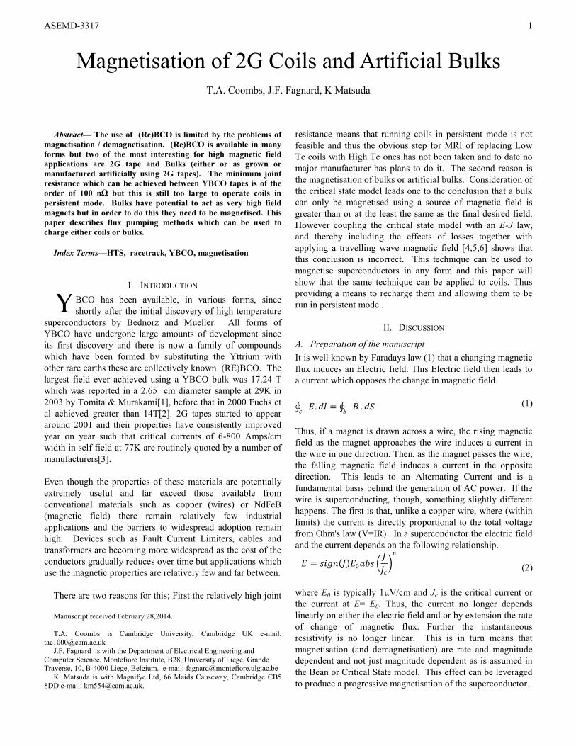
ASEMD-3317 1 Magnetisation of 2G Coils and Artificial Bulks T.A. Coombs, J.F. Fagnard, K Matsuda Abstract— The use of (Re)BCO is limited by the problems of magnetisation / demagnetisation. (Re)BCO is available in many forms but two of the most interesting for high magnetic field applications are 2G tape and Bulks (either or as grown or manufactured artificially using 2G tapes). The minimum joint resistance which can be achieved between YBCO tapes is of the order of 100 nΩ but this is still too large to operate coils in persistent mode. Bulks have potential to act as very high field magnets but in order to do this they need to be magnetised. This paper describes flux pumping methods which can be used to charge either coils or bulks. Index Terms—HTS, racetrack, YBCO, magnetisation I. INTRODUCTION BCO has been available, in various forms, since shortly after the initial discovery of high temperature superconductors by Bednorz and Mueller. All forms of YBCO have undergone large amounts of development since its first discovery and there is now a family of compounds which have been formed by substituting the Yttrium with other rare earths these are collectively known (RE)BCO. The largest field ever achieved using a YBCO bulk was 17.24 T which was reported in a 2.65 cm diameter sample at 29K in 2003 by Tomita & Murakami[1], before that in 2000 Fuchs et al achieved greater than 14T[2]. 2G tapes started to appear around 2001 and their properties have consistently improved year on year such that critical currents of 6-800 Amps/cm width in self field at 77K are routinely quoted by a number of manufacturers[3]. Even though the properties of these materials are potentially extremely useful and far exceed those available from conventional materials such as copper (wires) or NdFeB (magnetic field) there remain relatively few industrial applications and the barriers to widespread adoption remain high. Devices such as Fault Current Limiters, cables and transformers are becoming more widespread as the cost of the conductors gradually reduces over time but applications which use the magnetic properties are relatively few and far between. There are two reasons for this; First the relatively high joint Manuscript received February 28,2014. T.A. Coombs is Cambridge University, Cambridge UK e-mail: [email protected] J.F. Fagnard is with the Department of Electrical Engineering and Computer Science, Montefiore Institute, B28, University of Liege, Grande Traverse, 10, B-4000 Liege, Belgium. e-mail: [email protected] K. Matsuda is with Magnifye Ltd, 66 Maids Causeway, Cambridge CB5 8DD e-mail: [email protected]. resistance means that running coils in persistent mode is not feasible and thus the obvious step for MRI of replacing Low Tc coils with High Tc ones has not been taken and to date no major manufacturer has plans to do it. The second reason is the magnetisation of bulks or artificial bulks. Consideration of the critical state model leads one to the conclusion that a bulk can only be magnetised using a source of magnetic field is greater than or at the least the same as the final desired field. However coupling the critical state model with an E-J law, and thereby including the effects of losses together with applying a travelling wave magnetic field [4,5,6] shows that this conclusion is incorrect. This technique can be used to magnetise superconductors in any form and this paper will show that the same technique can be applied to coils. Thus providing a means to recharge them and allowing them to be run in persistent mode.. II. DISCUSSION A. Preparation of the manuscript It is well known by Faradays law (1) that a changing magnetic flux induces an Electric field. This Electric field then leads to a current which opposes the change in magnetic field. . = . (1) Thus, if a magnet is drawn across a wire, the rising magnetic field as the magnet approaches the wire induces a current in the wire in one direction. Then, as the magnet passes the wire, the falling magnetic field induces a current in the opposite direction. This leads to an Alternating Current and is a fundamental basis behind the generation of AC power. If the wire is superconducting, though, something slightly different happens. The first is that, unlike a copper wire, where (within limits) the current is directly proportional to the total voltage from Ohm's law (V=IR) . In a superconductor the electric field and the current depends on the following relationship. = 0 (2) where E 0 is typically 1μV/cm and J c is the critical current or the current at E= E 0 . Thus, the current no longer depends linearly on either the electric field and or by extension the rate of change of magnetic flux. Further the instantaneous resistivity is no longer linear. This is in turn means that magnetisation (and demagnetisation) are rate and magnitude dependent and not just magnitude dependent as is assumed in the Bean or Critical State model. This effect can be leveraged to produce a progressive magnetisation of the superconductor. Y
Transcript of Magnetisation of 2G Coils and Artificial Bulks
ASEMD-3317
1
Magnetisation of 2G Coils and Artificial Bulks
T.A. Coombs, J.F. Fagnard, K Matsuda
Abstract— The use of (Re)BCO is limited by the problems of
magnetisation / demagnetisation. (Re)BCO is available in many
forms but two of the most interesting for high magnetic field
applications are 2G tape and Bulks (either or as grown or
manufactured artificially using 2G tapes). The minimum joint
resistance which can be achieved between YBCO tapes is of the
order of 100 nΩ but this is still too large to operate coils in
persistent mode. Bulks have potential to act as very high field
magnets but in order to do this they need to be magnetised. This
paper describes flux pumping methods which can be used to
charge either coils or bulks.
Index Terms—HTS, racetrack, YBCO, magnetisation
I. INTRODUCTION
BCO has been available, in various forms, since
shortly after the initial discovery of high temperature
superconductors by Bednorz and Mueller. All forms of
YBCO have undergone large amounts of development since
its first discovery and there is now a family of compounds
which have been formed by substituting the Yttrium with
other rare earths these are collectively known (RE)BCO. The
largest field ever achieved using a YBCO bulk was 17.24 T
which was reported in a 2.65 cm diameter sample at 29K in
2003 by Tomita & Murakami[1], before that in 2000 Fuchs et
al achieved greater than 14T[2]. 2G tapes started to appear
around 2001 and their properties have consistently improved
year on year such that critical currents of 6-800 Amps/cm
width in self field at 77K are routinely quoted by a number of
manufacturers[3].
Even though the properties of these materials are potentially
extremely useful and far exceed those available from
conventional materials such as copper (wires) or NdFeB
(magnetic field) there remain relatively few industrial
applications and the barriers to widespread adoption remain
high. Devices such as Fault Current Limiters, cables and
transformers are becoming more widespread as the cost of the
conductors gradually reduces over time but applications which
use the magnetic properties are relatively few and far between.
There are two reasons for this; First the relatively high joint
Manuscript received February 28,2014.
T.A. Coombs is Cambridge University, Cambridge UK e-mail: [email protected]
J.F. Fagnard is with the Department of Electrical Engineering and
Computer Science, Montefiore Institute, B28, University of Liege, Grande Traverse, 10, B-4000 Liege, Belgium. e-mail: [email protected]
K. Matsuda is with Magnifye Ltd, 66 Maids Causeway, Cambridge CB5
8DD e-mail: [email protected].
resistance means that running coils in persistent mode is not
feasible and thus the obvious step for MRI of replacing Low
Tc coils with High Tc ones has not been taken and to date no
major manufacturer has plans to do it. The second reason is
the magnetisation of bulks or artificial bulks. Consideration of
the critical state model leads one to the conclusion that a bulk
can only be magnetised using a source of magnetic field is
greater than or at the least the same as the final desired field.
However coupling the critical state model with an E-J law,
and thereby including the effects of losses together with
applying a travelling wave magnetic field [4,5,6] shows that
this conclusion is incorrect. This technique can be used to
magnetise superconductors in any form and this paper will
show that the same technique can be applied to coils. Thus
providing a means to recharge them and allowing them to be
run in persistent mode..
II. DISCUSSION
A. Preparation of the manuscript
It is well known by Faradays law (1) that a changing magnetic
flux induces an Electric field. This Electric field then leads to
a current which opposes the change in magnetic field.
𝐸. 𝑑𝑙𝑐
= 𝐵 𝑆
. 𝑑𝑆 (1)
Thus, if a magnet is drawn across a wire, the rising magnetic
field as the magnet approaches the wire induces a current in
the wire in one direction. Then, as the magnet passes the wire,
the falling magnetic field induces a current in the opposite
direction. This leads to an Alternating Current and is a
fundamental basis behind the generation of AC power. If the
wire is superconducting, though, something slightly different
happens. The first is that, unlike a copper wire, where (within
limits) the current is directly proportional to the total voltage
from Ohm's law (V=IR) . In a superconductor the electric field
and the current depends on the following relationship.
𝐸 = 𝑠𝑖𝑔𝑛 𝐽 𝐸0𝑎𝑏𝑠 𝐽
𝐽𝑐 𝑛
(2)
where E0 is typically 1µV/cm and Jc is the critical current or
the current at E= E0. Thus, the current no longer depends
linearly on either the electric field and or by extension the rate
of change of magnetic flux. Further the instantaneous
resistivity is no longer linear. This is in turn means that
magnetisation (and demagnetisation) are rate and magnitude
dependent and not just magnitude dependent as is assumed in
the Bean or Critical State model. This effect can be leveraged
to produce a progressive magnetisation of the superconductor.
Y
ASEMD-3317
2
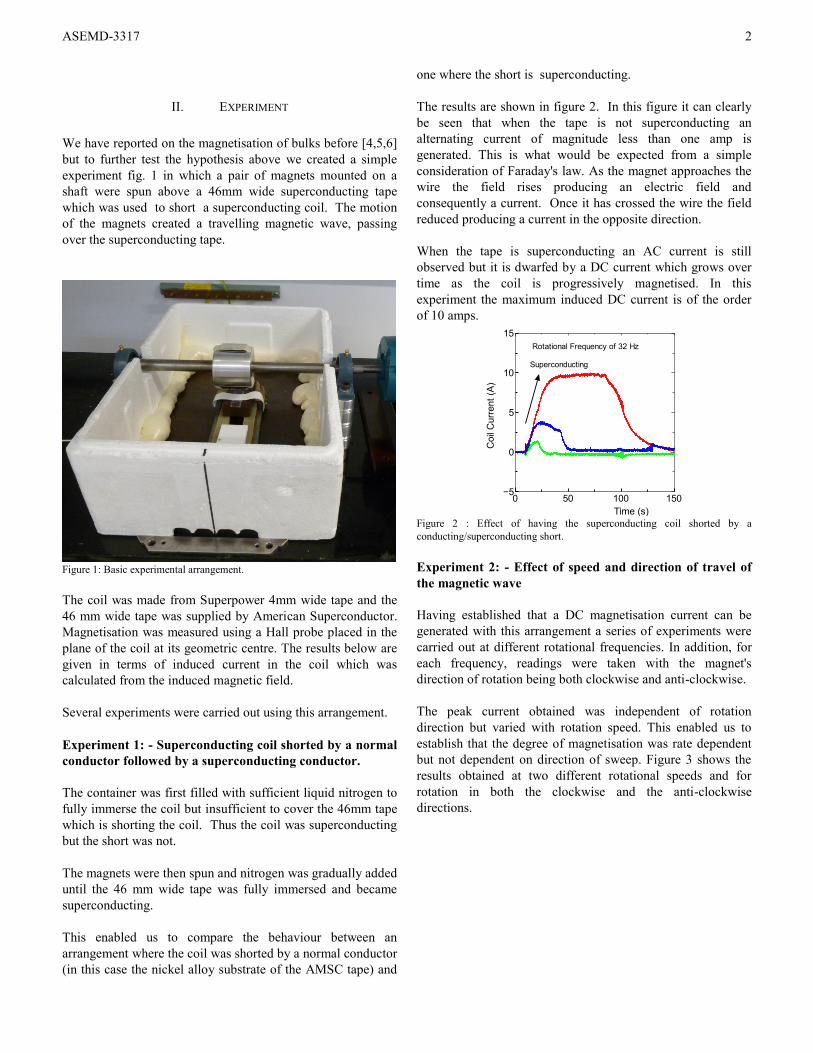
II. EXPERIMENT
We have reported on the magnetisation of bulks before [4,5,6]
but to further test the hypothesis above we created a simple
experiment fig. 1 in which a pair of magnets mounted on a
shaft were spun above a 46mm wide superconducting tape
which was used to short a superconducting coil. The motion
of the magnets created a travelling magnetic wave, passing
over the superconducting tape.
Figure 1: Basic experimental arrangement.
The coil was made from Superpower 4mm wide tape and the
46 mm wide tape was supplied by American Superconductor.
Magnetisation was measured using a Hall probe placed in the
plane of the coil at its geometric centre. The results below are
given in terms of induced current in the coil which was
calculated from the induced magnetic field.
Several experiments were carried out using this arrangement.
Experiment 1: - Superconducting coil shorted by a normal
conductor followed by a superconducting conductor.
The container was first filled with sufficient liquid nitrogen to
fully immerse the coil but insufficient to cover the 46mm tape
which is shorting the coil. Thus the coil was superconducting
but the short was not.
The magnets were then spun and nitrogen was gradually added
until the 46 mm wide tape was fully immersed and became
superconducting.
This enabled us to compare the behaviour between an
arrangement where the coil was shorted by a normal conductor
(in this case the nickel alloy substrate of the AMSC tape) and
one where the short is superconducting.
The results are shown in figure 2. In this figure it can clearly
be seen that when the tape is not superconducting an
alternating current of magnitude less than one amp is
generated. This is what would be expected from a simple
consideration of Faraday's law. As the magnet approaches the
wire the field rises producing an electric field and
consequently a current. Once it has crossed the wire the field
reduced producing a current in the opposite direction.
When the tape is superconducting an AC current is still
observed but it is dwarfed by a DC current which grows over
time as the coil is progressively magnetised. In this
experiment the maximum induced DC current is of the order
of 10 amps.
0 50 100 150−5
0
5
10
15
Coil
Curr
ent
(A)
Time (s)
Rotational Frequency of 32 Hz
Superconducting
Figure 2 : Effect of having the superconducting coil shorted by a
conducting/superconducting short.
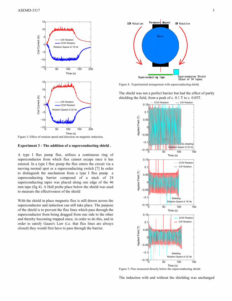
Experiment 2: - Effect of speed and direction of travel of
the magnetic wave
Having established that a DC magnetisation current can be
generated with this arrangement a series of experiments were
carried out at different rotational frequencies. In addition, for
each frequency, readings were taken with the magnet's
direction of rotation being both clockwise and anti-clockwise.
The peak current obtained was independent of rotation
direction but varied with rotation speed. This enabled us to
establish that the degree of magnetisation was rate dependent
but not dependent on direction of sweep. Figure 3 shows the
results obtained at two different rotational speeds and for
rotation in both the clockwise and the anti-clockwise
directions.
ASEMD-3317
3
0 50 100 150 200−15
−10
−5
0
5
10
15
Coil
Curr
ent
(A)
Time (s)
CW Rotation
CCW Rotation
Rotation Speed of 18 Hz
0 50 100 150 200−15
−10
−5
0
5
10
15
Coil
Curr
ent
(A)
Time (s)
CW Rotation
CCW Rotation
Rotation Speed of 32 Hz
Figure 3: Effect of rotation speed and direction on magnetic induction.
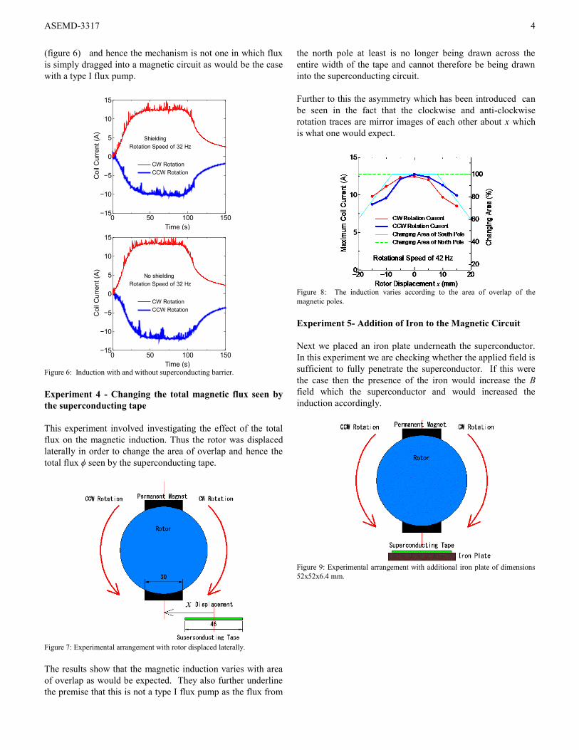
Experiment 3 - The addition of a superconducting shield .
A type I flux pump flux, utilises a continuous ring of
superconductor from which flux cannot escape once it has
entered. In a type I flux pump the flux enters the circuit via a
moving normal spot or a superconducting switch [7] In order
to distinguish the mechanism from a type I flux pump a
superconducting barrier composed of a stack of 24
superconducting tapes was placed along one edge of the 46
mm tape (fig 4). A Hall probe place below the shield was used
to measure the effectiveness of the shield
With the shield in place magnetic flux is still drawn across the
superconductor and induction can still take place. The purpose
of the shield is to prevent the flux lines which pass through the
superconductor from being dragged from one side to the other
and thereby becoming trapped since, in order to do this, and in
order to satisfy Gauss's Law (i.e. that flux lines are always
closed) they would first have to pass through the barrier.
Figure 4: Experimental arrangement with superconducting shield.
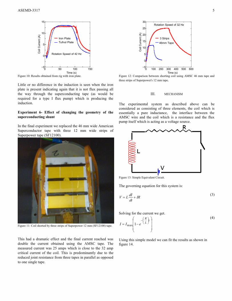
The shield was not a perfect barrier but had the effect of partly
shielding the field, from a peak of c. 0.1 T to c. 0.05T.
0 50 100 150−0.15
−0.1
−0.05
0
0.05
0.1
0.15
Applie
d F
ield
(T
)
Time (s)
Rotation Speed of 32 Hz
CCW Rotation CW Rotation
No shielding
0 50 100 150−0.15
−0.1
−0.05
0
0.05
0.1
0.15
Applie
d F
ield
(T
)
Time (s)
Rotation Speed of 18 Hz
CCW Rotation
CW Rotation
Shielding
0 50 100 150−0.15
−0.1
−0.05
0
0.05
0.1
0.15
Applie
d F
ield
(T
)
Time (s)
Rotation Speed of 32 Hz
CCW Rotation
CW Rotation
Shielding
Figure 5: Flux measured directly below the superconducting shield.
The induction with and without the shielding was unchanged
ASEMD-3317
4
(figure 6) and hence the mechanism is not one in which flux
is simply dragged into a magnetic circuit as would be the case
with a type I flux pump.
0 50 100 150−15
−10
−5
0
5
10
15C
oil
Curr
ent
(A)
Time (s)
CW Rotation
CCW Rotation
Rotation Speed of 32 Hz
Shielding
0 50 100 150−15
−10
−5
0
5
10
15
Coil
Curr
ent
(A)
Time (s)
CW Rotation
CCW Rotation
Rotation Speed of 32 Hz
No shielding
Figure 6: Induction with and without superconducting barrier.
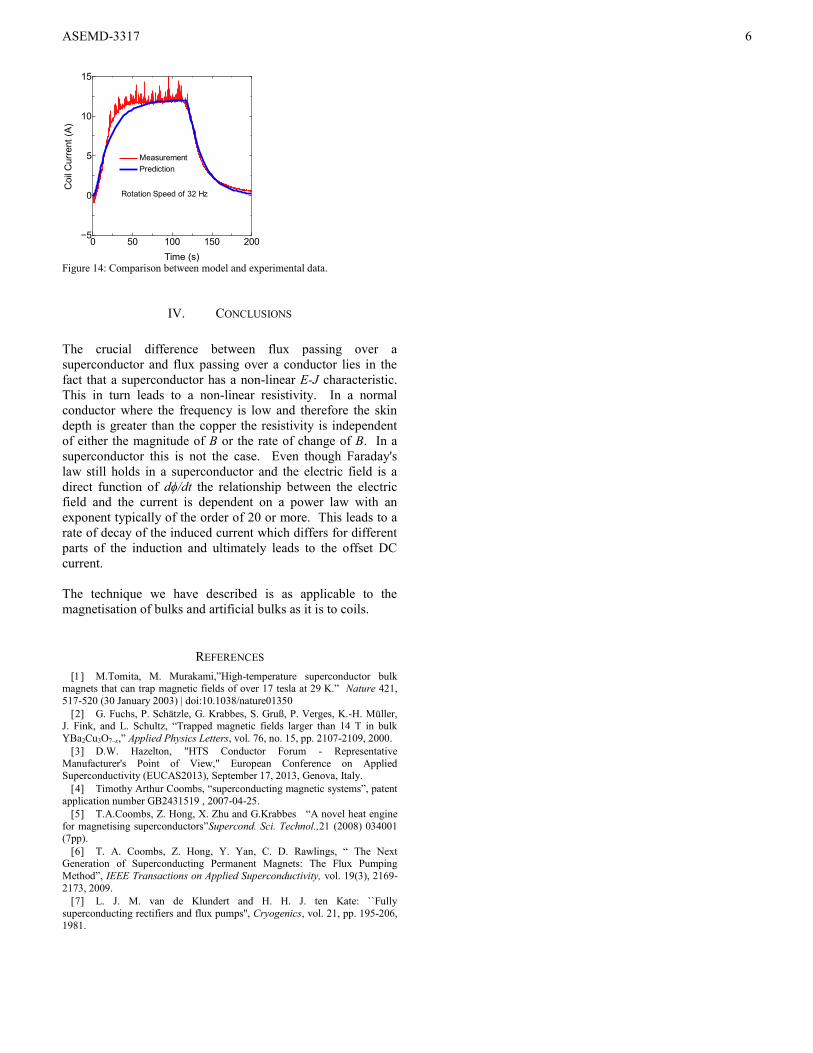
Experiment 4 - Changing the total magnetic flux seen by
the superconducting tape
This experiment involved investigating the effect of the total
flux on the magnetic induction. Thus the rotor was displaced
laterally in order to change the area of overlap and hence the
total flux ϕ seen by the superconducting tape.
Figure 7: Experimental arrangement with rotor displaced laterally.
The results show that the magnetic induction varies with area
of overlap as would be expected. They also further underline
the premise that this is not a type I flux pump as the flux from
the north pole at least is no longer being drawn across the
entire width of the tape and cannot therefore be being drawn
into the superconducting circuit.
Further to this the asymmetry which has been introduced can
be seen in the fact that the clockwise and anti-clockwise
rotation traces are mirror images of each other about x which
is what one would expect.
Figure 8: The induction varies according to the area of overlap of the
magnetic poles.
Experiment 5- Addition of Iron to the Magnetic Circuit
Next we placed an iron plate underneath the superconductor.
In this experiment we are checking whether the applied field is
sufficient to fully penetrate the superconductor. If this were
the case then the presence of the iron would increase the B
field which the superconductor and would increased the
induction accordingly.
Figure 9: Experimental arrangement with additional iron plate of dimensions
52x52x6.4 mm.
ASEMD-3317
5
0 50 100 150−5
0
5
10
15
Coil
Curr
ent
(A)
Time (s)
Rotation Speed of 42 Hz
Iron Plate
Tufnol Plate
Figure 10: Results obtained from rig with iron plate.
Little or no difference in the induction is seen when the iron
plate is present indicating again that it is not flux passing all
the way through the superconducting tape (as would be
required for a type I flux pump) which is producing the
induction.
Experiment 6- Effect of changing the geometry of the
superconducting shunt
In the final experiment we replaced the 46 mm wide American
Superconductor tape with three 12 mm wide strips of
Superpower tape (SF12100).
Figure 11: Coil shorted by three strips of Superpower 12 mm (SF12100) tape.
This had a dramatic effect and the final current reached was
double the current obtained using the AMSC tape. The
measured current was 25 amps which is close to the 32 amp
critical current of the coil. This is predominantly due to the
reduced joint resistance from three tapes in parallel as opposed
to one single tape.
0 100 200 300 400 500 600−5
0
5
10
15
20
25
30
Coil
Curr
ent
(A)
Time (s)
Rotation Speed of 32 Hz
3 Strips
46mm Tape
Figure 12: Comparison between shorting coil using AMSC 46 mm tape and
three strips of Superpower's 12 mm tape.
III. MECHANISM
The experimental system as described above can be
considered as consisting of three elements, the coil which is
essentially a pure inductance, the interface between the
AMSC wire and the coil which is a resistance and the flux
pump itself which is acting as a voltage source.
Figure 13: Simple Equivalent Circuit.
The governing equation for this system is:
IRdt
dILV
(3)
Solving for the current we get.
t
L
R
eII 1max
(4)
Using this simple model we can fit the results as shown in
figure 14.
ASEMD-3317
6
0 50 100 150 200−5
0
5
10
15C
oil
Curr
ent
(A)
Time (s)
Measurement
Prediction
Rotation Speed of 32 Hz
Figure 14: Comparison between model and experimental data.
IV. CONCLUSIONS
The crucial difference between flux passing over a
superconductor and flux passing over a conductor lies in the
fact that a superconductor has a non-linear E-J characteristic.
This in turn leads to a non-linear resistivity. In a normal
conductor where the frequency is low and therefore the skin
depth is greater than the copper the resistivity is independent
of either the magnitude of B or the rate of change of B. In a
superconductor this is not the case. Even though Faraday's
law still holds in a superconductor and the electric field is a
direct function of dϕ/dt the relationship between the electric
field and the current is dependent on a power law with an
exponent typically of the order of 20 or more. This leads to a
rate of decay of the induced current which differs for different
parts of the induction and ultimately leads to the offset DC
current.
The technique we have described is as applicable to the
magnetisation of bulks and artificial bulks as it is to coils.
REFERENCES
M.Tomita, M. Murakami,”High-temperature superconductor bulk
magnets that can trap magnetic fields of over 17 tesla at 29 K.” Nature 421,
517-520 (30 January 2003) | doi:10.1038/nature01350
G. Fuchs, P. Schätzle, G. Krabbes, S. Gruß, P. Verges, K.-H. Müller, J. Fink, and L. Schultz, “Trapped magnetic fields larger than 14 T in bulk
YBa2Cu3O7–x,” Applied Physics Letters, vol. 76, no. 15, pp. 2107-2109, 2000.
D.W. Hazelton, "HTS Conductor Forum - Representative
Manufacturer's Point of View," European Conference on Applied Superconductivity (EUCAS2013), September 17, 2013, Genova, Italy.
Timothy Arthur Coombs, “superconducting magnetic systems”, patent
application number GB2431519 , 2007-04-25.
T.A.Coombs, Z. Hong, X. Zhu and G.Krabbes “A novel heat engine
for magnetising superconductors”Supercond. Sci. Technol.,21 (2008) 034001 (7pp).
T. A. Coombs, Z. Hong, Y. Yan, C. D. Rawlings, “ The Next Generation of Superconducting Permanent Magnets: The Flux Pumping
Method”, IEEE Transactions on Applied Superconductivity, vol. 19(3), 2169-
2173, 2009.
L. J. M. van de Klundert and H. H. J. ten Kate: ``Fully
superconducting rectifiers and flux pumps'', Cryogenics, vol. 21, pp. 195-206, 1981.