Magnetics constants
22
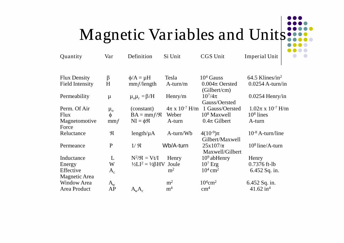
Magnetic Variables and Units Magnetic Variables and Units Quantity Var Definition Si Unit CGS Unit Imperial Unit Flux Density /A = μH Tesla 10 4 Gauss 64.5 Klines/in 2 Field Intensity H mmƒ/length A-turn/m 0.004 Oersted 0.0254 A-turn/in (Gilbert/cm) Permeability μ μ o μ r = /H Henry/m 10 7 /4 0.0254 Henry/in Gauss/Oersted Perm. Of Air μ o (constant) 4 x 10 -7 H/m 1 Gauss/Oersted 1.02 x 10 -7 H/m Flux BA = mmƒ/ Weber 10 8 Maxwell 10 8 lines Magnetomotive mmƒ NI = A-turn 0.4 Gilbert A-turn Force Reluctance length/μA A-turn/Wb 4(10 -9 ) 10 -8 A-turn/line Gilbert/Maxwell Permeance Р 1/ Wb/A-turn 25x107/π 10 8 line/A-turn Maxwell/Gilbert Inductance L N 2 / = Vt/I Henry 10 9 abHenry Henry Energy W ½LI 2 =½HV Joule 10 7 Erg 0.7376 ft-lb Effective A c m 2 10 4 cm 2 6.452 Sq. in. Magnetic Area Window Area A w m 2 10 4 cm 2 6.452 Sq. in. Area Product AP A w A c m 4 cm 4 41.62 in 4
-
Upload
paolo-steven-polintan -
Category
Documents
-
view
252 -
download
3
Transcript of Magnetics constants
Magnetic Variables and UnitsMagnetic Variables and UnitsQuantity Var Definition Si Unit CGS Unit Imperial Unit
Flux Density /A = µH Tesla 104 Gauss 64.5 Klines/in2
Field Intensity H mmƒ/length A-turn/m 0.004 Oersted 0.0254 A-turn/in(Gilbert/cm)
Permeability µ µoµr = /H Henry/m 107/4 0.0254 Henry/inGauss/Oersted
Perm. Of Air µo (constant) 4 x 10⁻⁷ H/m 1 Gauss/Oersted 1.02 x 10⁻⁷ H/mFlux BA = mmƒ/ Weber 108 Maxwell 108 linesMagnetomotive mmƒ NI = A-turn 0.4 Gilbert A-turnForceReluctance length/µA A-turn/Wb 4(10-9) 10-8 A-turn/line
Gilbert/MaxwellPermeance Р 1/ Wb/A-turn 25x107/π 108 line/A-turn
Maxwell/GilbertInductance L N2/ = Vt/I Henry 109 abHenry HenryEnergy W ½LI2 = ½HV Joule 107 Erg 0.7376 ft-lbEffective Ac m2 104 cm2 6.452 Sq. in.Magnetic AreaWindow Area Aw m2 104cm2 6.452 Sq. in.Area Product AP AwAc m4 cm4 41.62 in4
Ampere’s Law
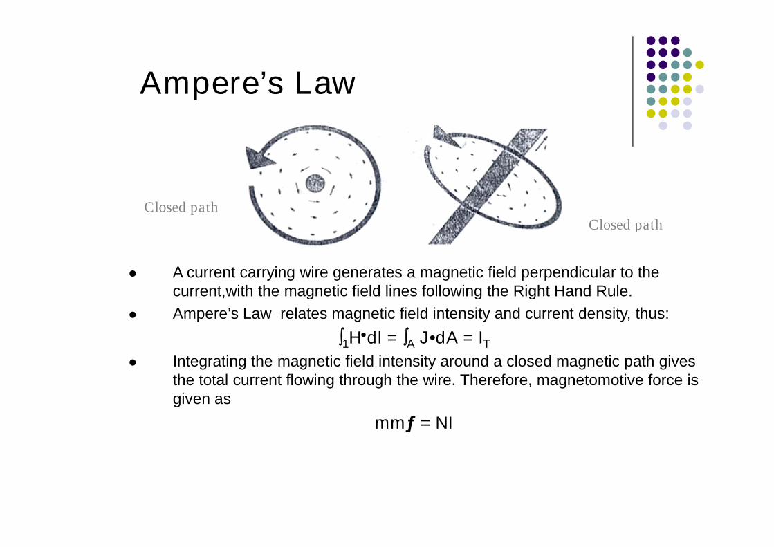
A current carrying wire generates a magnetic field perpendicular to thecurrent,with the magnetic field lines following the Right Hand Rule.
Ampere’s Law relates magnetic field intensity and current density, thus:
1Hdl = A J•dA = IT
Integrating the magnetic field intensity around a closed magnetic path givesthe total current flowing through the wire. Therefore, magnetomotive force isgiven as
mmƒ = NI
Closed pathClosed path

Faraday’s Law
Faraday’s Law is the complement of Ampere’s Law and relateselectric field intensity and magnetic flux density, thus:
1 E•dl = -/t A B•dA
The voltage induced in a conductor is proportional to the change inmagnetic flux passing through the surface enclosed by theconductor.
V = Nd/dt
A
I
+
-
Current and Magnetic Fields
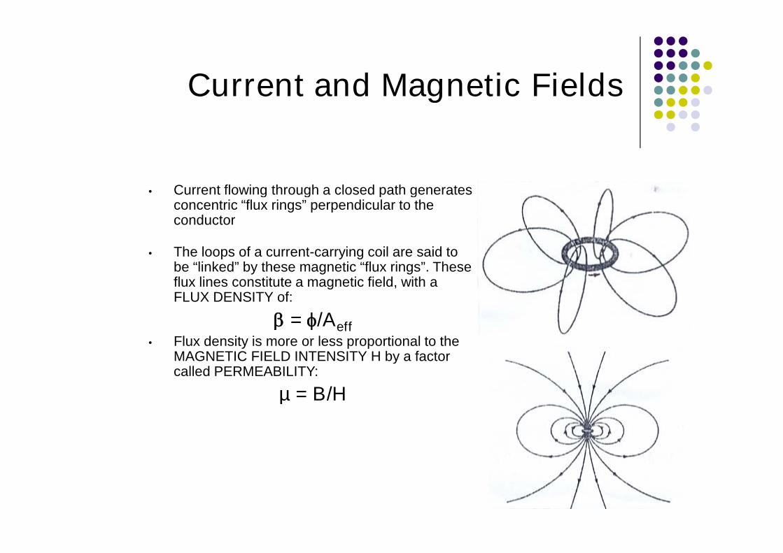
• Current flowing through a closed path generatesconcentric “flux rings” perpendicular to theconductor
• The loops of a current-carrying coil are said tobe “linked” by these magnetic “flux rings”. Theseflux lines constitute a magnetic field, with aFLUX DENSITY of:
= /Aeff• Flux density is more or less proportional to the
MAGNETIC FIELD INTENSITY H by a factorcalled PERMEABILITY:
µ = B/H

Inductance, L
• We are familiar with the equation:
V = Ldi/dt
• From Faradays Law:
V = NdΦ/dt
• Thus, Ldi = NdΦ
• Inductance is the ratio of the flux linkages NΦ in acoil to the current I which they link
L = NΦ/I
L = NBA/I

RELUCTANCERELUCTANCE
•Constricting the flux to flow through a specified magnetic path isanalogous to making current flow through an electric circuit.
•With a specified path, Ampere’s Law reduces to : Hℓ= NI
•Given that H = B/ and B = /Acore, we have: (ℓ/Acore) = NI
•Defining reluctance = ℓ/Acore, we have = NI = mmf
•This is analogous to Ohm’s Law: IR = V = emf
•Reluctance is therefore the “resistance” to the flow of flux, andcan be treated (connected in series or parallel) in the same wayas resistance.
EFFECTIVE RELATIVE PERMEABILITY OFEFFECTIVE RELATIVE PERMEABILITY OFGAPPED CORESGAPPED CORES
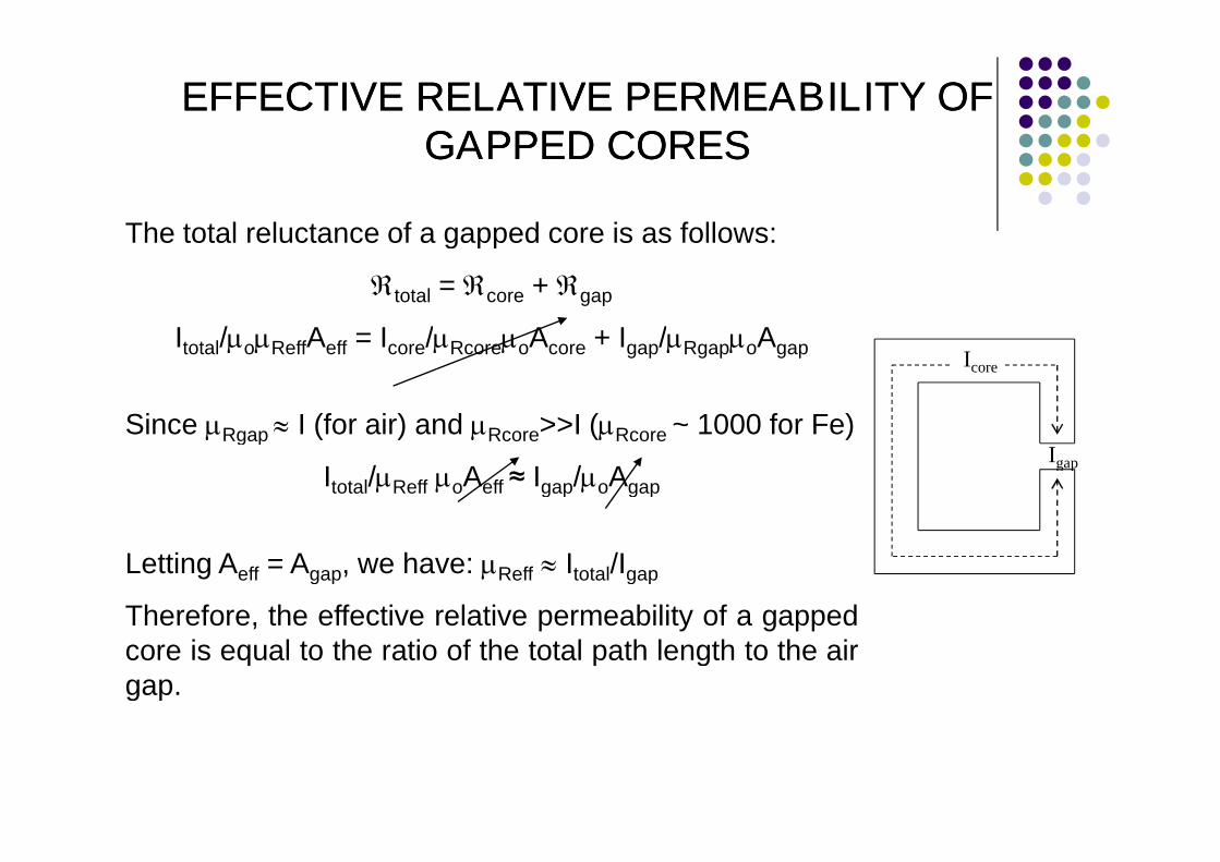
The total reluctance of a gapped core is as follows:
total = core + gap
Itotal/oReffAeff = Icore/RcoreoAcore + Igap/RgapoAgap
Since Rgap I (for air) and Rcore>>I (Rcore ~ 1000 for Fe)
Itotal/Reff oAeff ≈ Igap/oAgap
Letting Aeff = Agap, we have: Reff Itotal/Igap
Therefore, the effective relative permeability of a gappedcore is equal to the ratio of the total path length to the airgap.
Icore
Igap
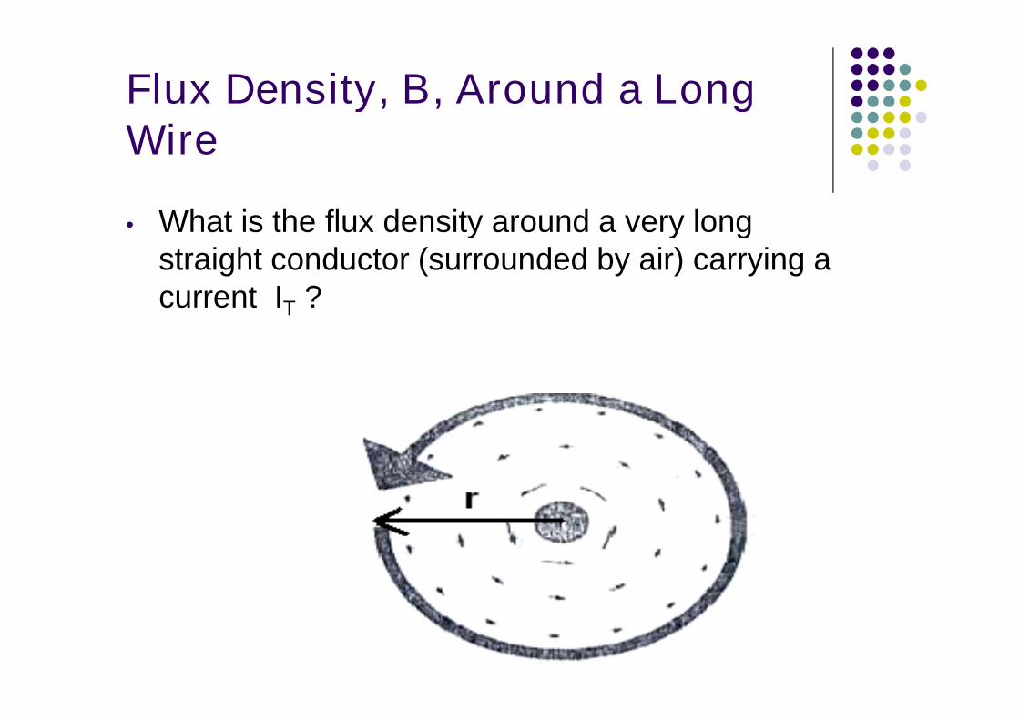
Flux Density, B, Around a LongWire
• What is the flux density around a very longstraight conductor (surrounded by air) carrying acurrent IT ?
Flux Density, B, in a Single-turnCoil
• Given a single-turn coil of radius r with acurrent Icoil flowing through it, what is the fluxdensity inside the coil?
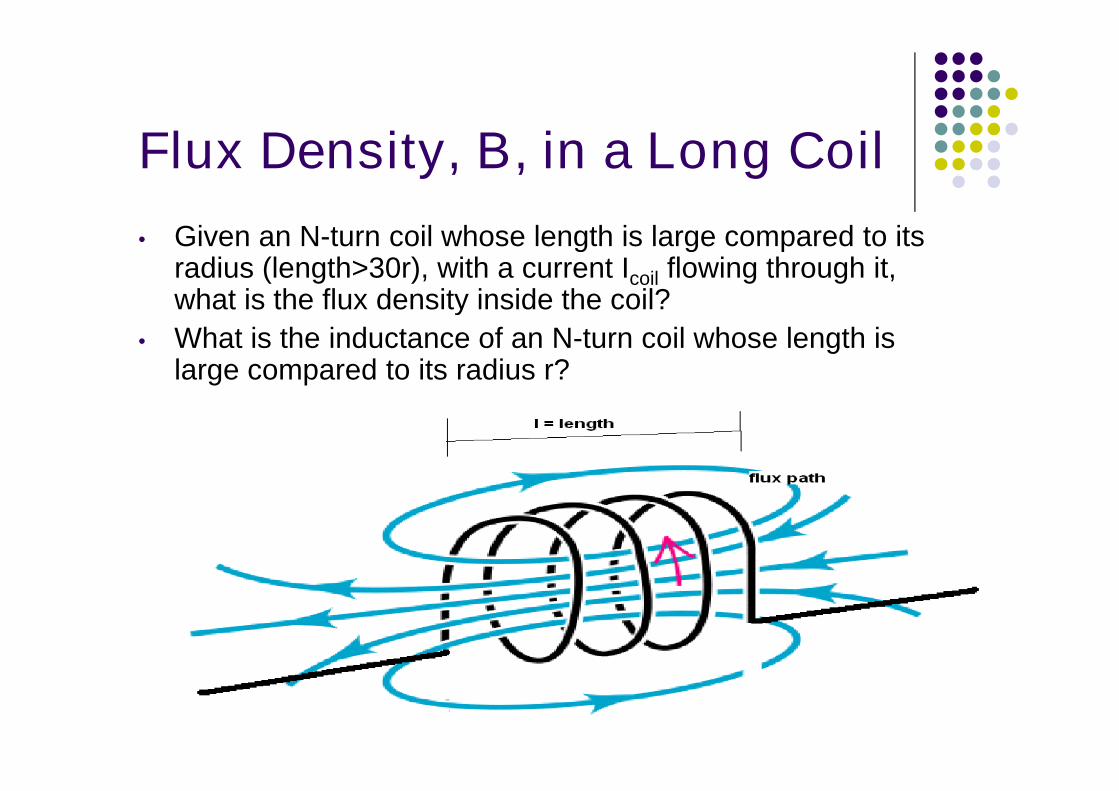
Flux Density, B, in a Long Coil
• Given an N-turn coil whose length is large compared to itsradius (length>30r), with a current Icoil flowing through it,what is the flux density inside the coil?
• What is the inductance of an N-turn coil whose length islarge compared to its radius r?
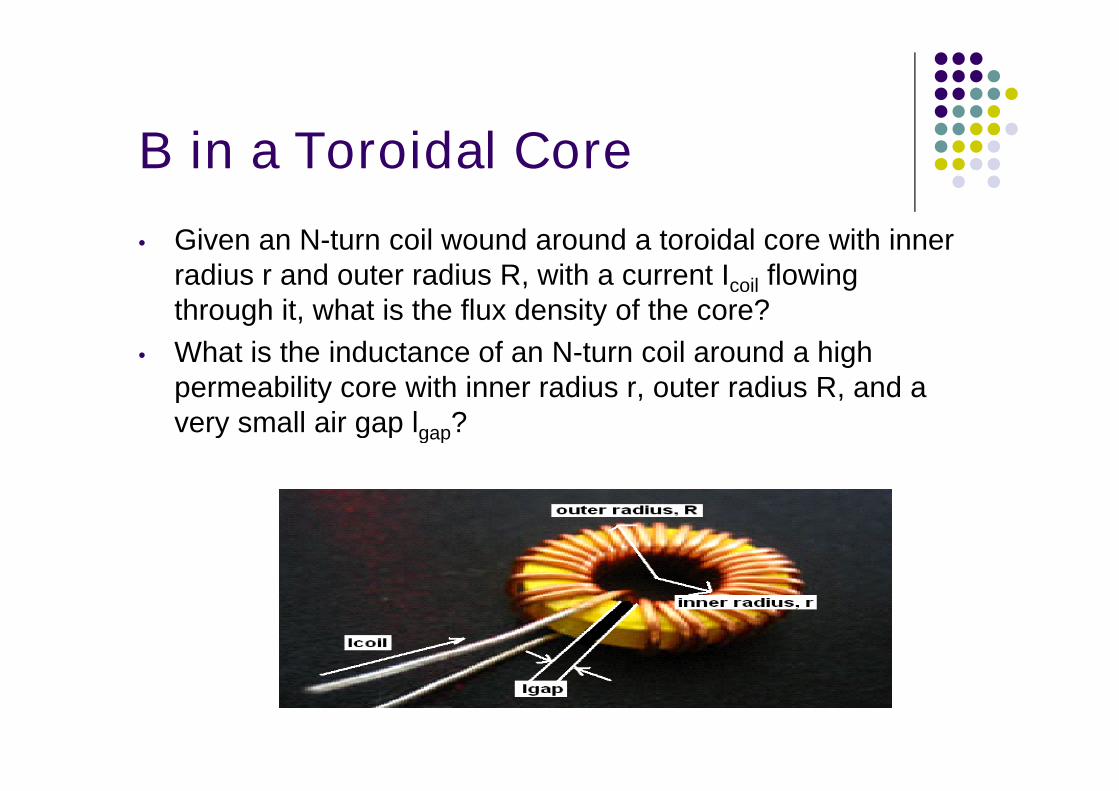
B in a Toroidal Core
• Given an N-turn coil wound around a toroidal core with innerradius r and outer radius R, with a current Icoil flowingthrough it, what is the flux density of the core?
• What is the inductance of an N-turn coil around a highpermeability core with inner radius r, outer radius R, and avery small air gap lgap?
Inductance of a C-core Inductor
• What is the inductance of an N-turn coilaround a high permeability core with innerradius r, outer radius R, and a very small airgap lgap?
Transformers
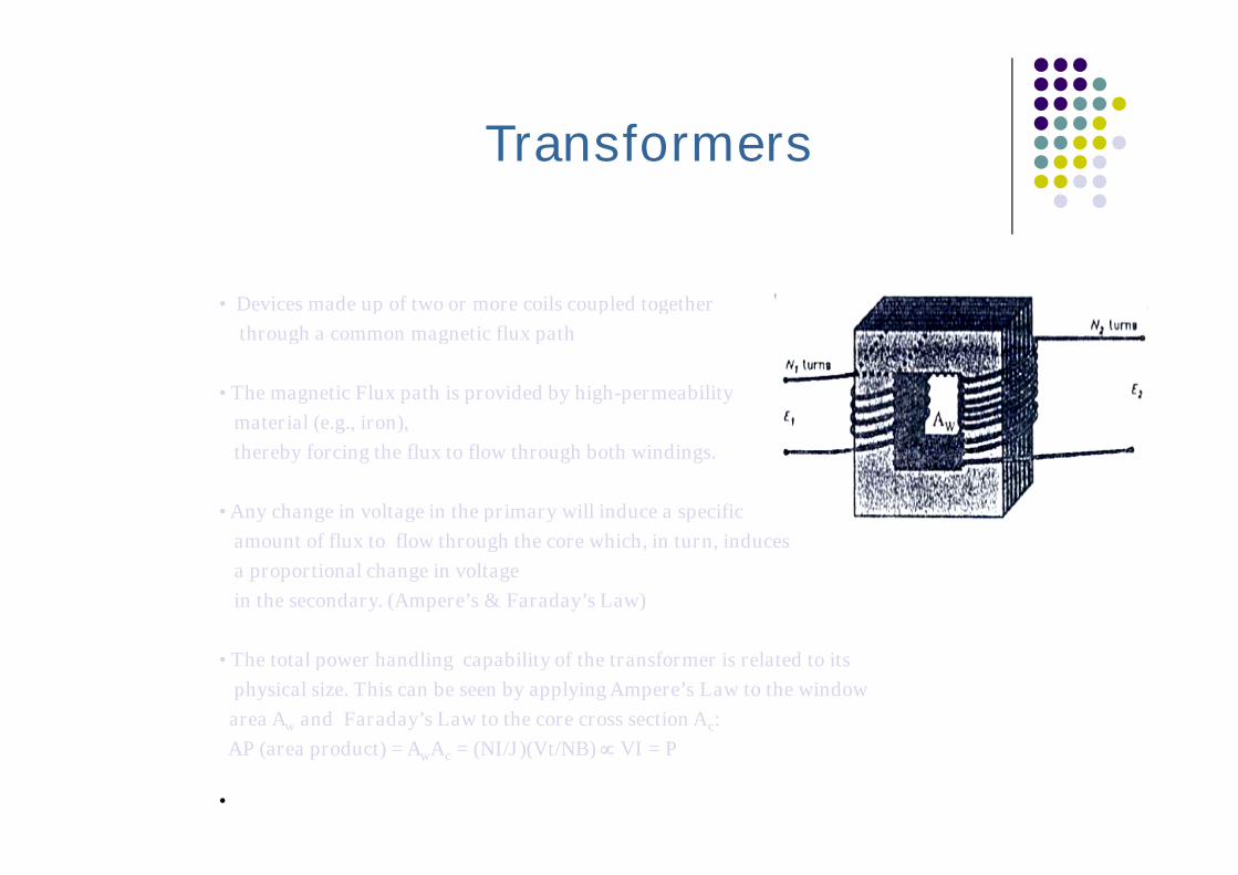
• Devices made up of two or more coils coupled together
through a common magnetic flux path
• The magnetic Flux path is provided by high-permeability
material (e.g., iron),
thereby forcing the flux to flow through both windings.
• Any change in voltage in the primary will induce a specific
amount of flux to flow through the core which, in turn, induces
a proportional change in voltage
in the secondary. (Ampere’s & Faraday’s Law)
• The total power handling capability of the transformer is related to its
physical size. This can be seen by applying Ampere’s Law to the window
area Aw and Faraday’s Law to the core cross section Ac:
AP (area product) = AwAc = (NI/J)(Vt/NB) VI = P
•
Transformer CharacteristicsTransformer Characteristics
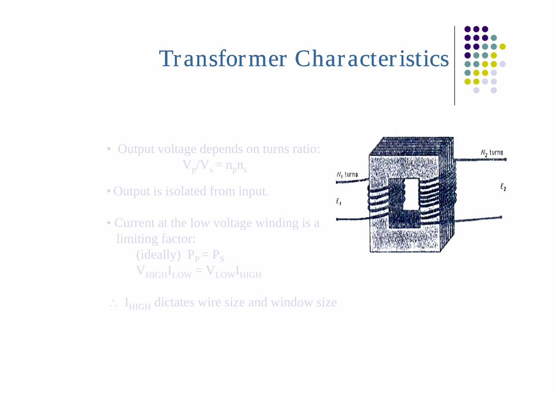
• Output voltage depends on turns ratio:Vp/Vs = npns
• Output is isolated from input.
• Current at the low voltage winding is alimiting factor:
(ideally) PP = PS
VHIGHILOW = VLOWIHIGH
IHIGH dictates wire size and window size
Core Saturation
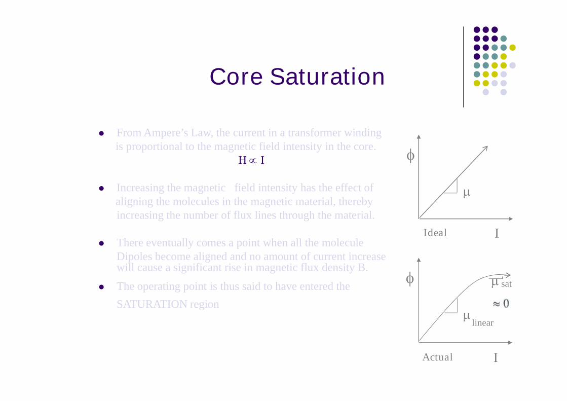
From Ampere’s Law, the current in a transformer windingis proportional to the magnetic field intensity in the core.
H I
Increasing the magnetic field intensity has the effect ofaligning the molecules in the magnetic material, therebyincreasing the number of flux lines through the material.
There eventually comes a point when all the moleculeDipoles become aligned and no amount of current increasewill cause a significant rise in magnetic flux density B.
The operating point is thus said to have entered the
SATURATION region
Ideal I
linear
sat
Actual I

Problem 1
1. Given a 350-turn coil whose length isequal to 400 mm and the radius is equalto 0.3 cm with a current of 1.5 A flowingthrough it. What is the flux density insidethe coil if μr = 3000? Also, calculate theinductance of the coil.
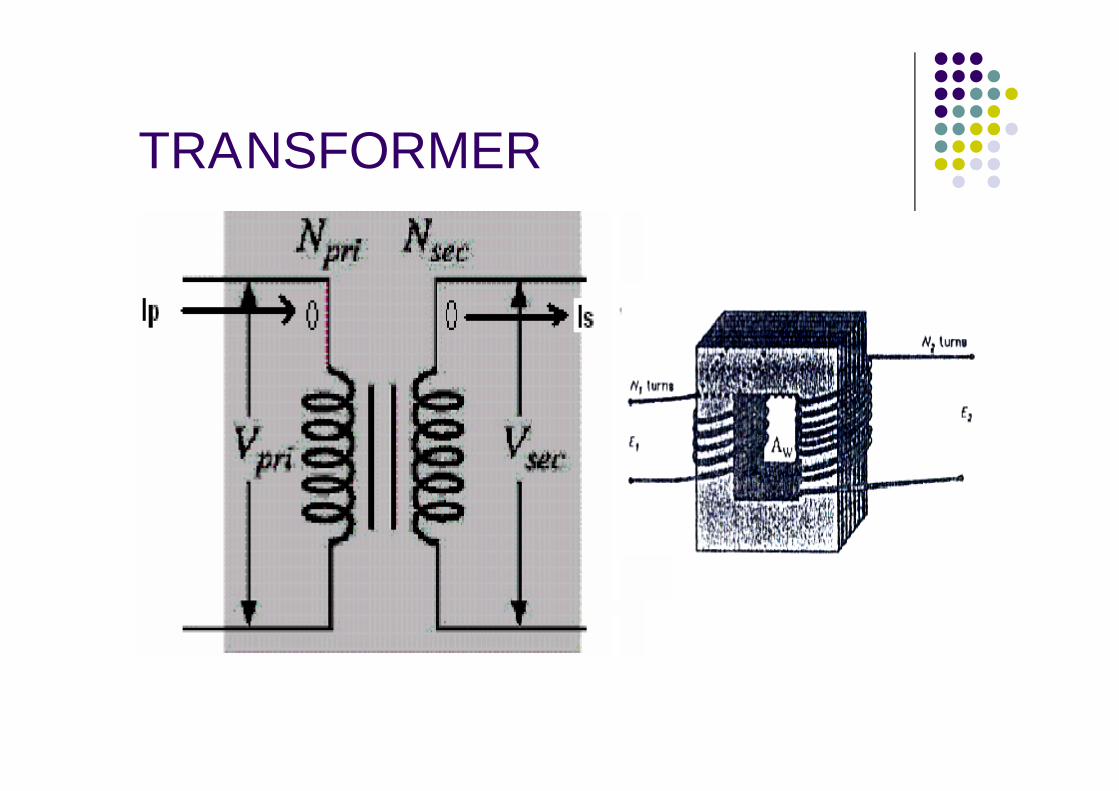
TRANSFORMER
Transformers
Devices made up of two or more coils coupledtogether through a common magnetic flux path whichcan step-up or step-down an AC voltage or current.
The turns ratio of the primary to secondary determinesthe output versus the input. Input power is ideallyequal to output power, voltage ratio is inverselyproportional to the current ratio.
Any change in voltage in the primary will induce aspecific amount of flux to flow through the core which,in turn, induces a proportional change in voltage in thesecondary. (Ampere’s & Faraday’s Law)
A magnetic flux path is provided by the iron plates,thereby coupling both the primary winding and thesecondary winding.
Output is isolated from the input.
Coupling Coefficient, K
Given that the primary coil and secondary coil havetheir own (“self”) inductance, these can be related tothe mutual inductance. The coupling coefficient K ofa transformer is defined as:
K = M/√(L1L2) < 1 where: L1 = self inductance of the primary L2 = self inductance of the secondary M = mutual inductance between coils K = 1 (ideal transformer, perfect coupling)

Current going into the dotted primaryterminal is transformed and goes out of thesecondary terminal.
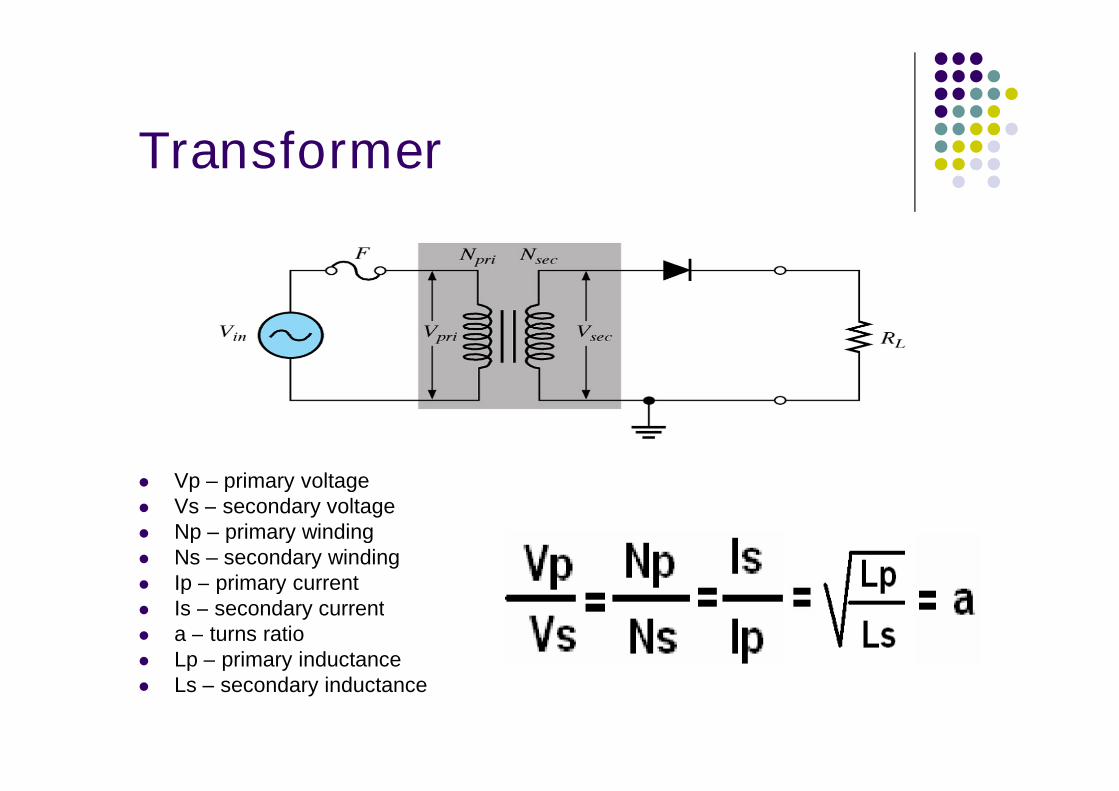
Transformer
Vp – primary voltage Vs – secondary voltage Np – primary winding Ns – secondary winding Ip – primary current Is – secondary current a – turns ratio Lp – primary inductance Ls – secondary inductance
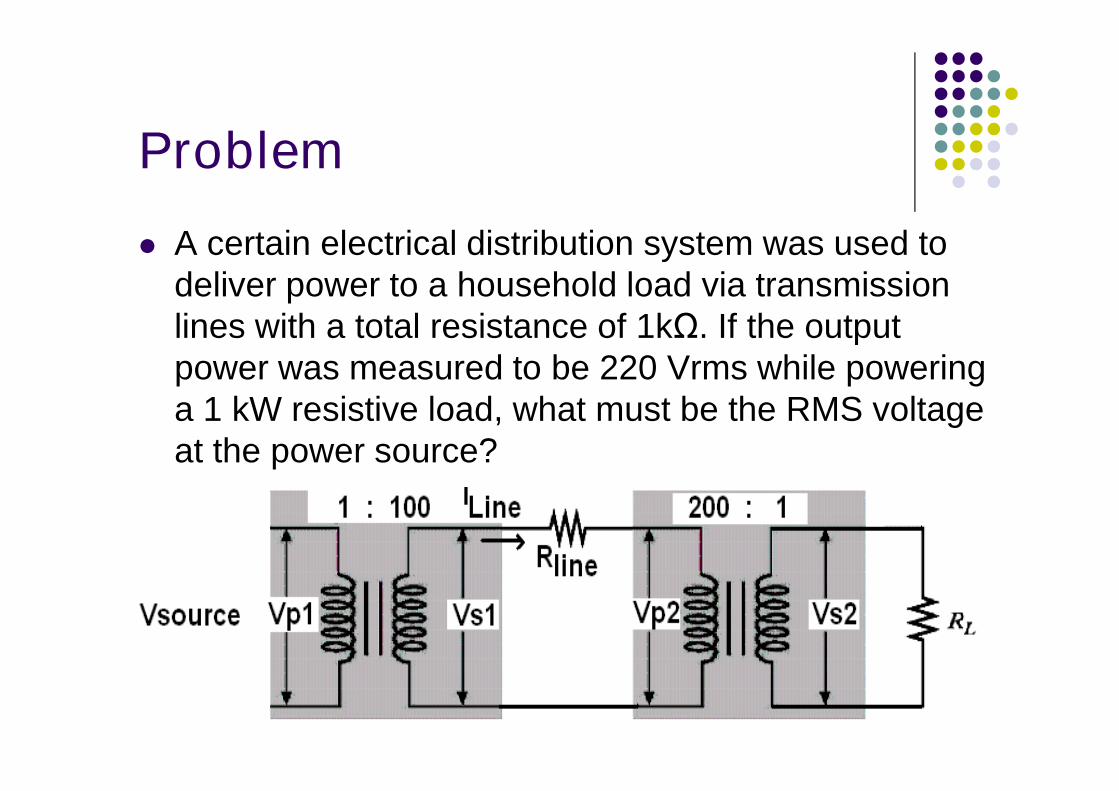
Problem
A certain electrical distribution system was used todeliver power to a household load via transmissionlines with a total resistance of 1kΩ. If the outputpower was measured to be 220 Vrms while poweringa 1 kW resistive load, what must be the RMS voltageat the power source?