Magnetic Vortex Dynamics Induced by an Electrical...
15
Magnetic Vortex Dynamics Induced by an Electrical Current YURI GAIDIDEI, 1 VOLODYMYR P. KRAVCHUK, 1 DENIS D. SHEKA 2 1 Institute for Theoretical Physics, 03680 Kiev, Ukraine 2 National Taras Shevchenko University of Kiev, 03127 Kiev, Ukraine Received 13 January 2009; accepted 10 March 2009 Published online 3 June 2009 in Wiley InterScience (www.interscience.wiley.com). DOI 10.1002/qua.22253 ABSTRACT: A magnetic nanoparticle in a vortex state is a promising candidate for the information storage. One bit of information corresponds to the upward or downward magnetization of the vortex core (vortex polarity). The dynamics of the magnetic vortex driven by a spin current is studied theoretically. Using a simple analytical model and numerical simulations, we show that a nondecaying vortex motion can be excited by a dc spin–polarized current, whose intensity exceeds a first threshold value as a result of the balance between a spin-torque pumping and damping forces. The irreversible switching of the vortex polarity takes place for a current above a second threshold. The mechanism of the switching, which involves the process of creation and annihilation of a vortex–antivortex pair is described analytically, using a rigid model, and confirmed by detailed spin–lattice simulations. © 2009 Wiley Periodicals, Inc. Int J Quantum Chem 110: 83–97, 2010 Key words: magnetic vortex; vortex polarity; micromagnetism; spin-polarized current 1. Introduction A strikingly rapid development of the elemen- tary base of systems of information storage Correspondence to: V. P. Kravchuk; e-mail: vkravchuk@bitp. kiev.ua Contract grant sponsor: Deutsches Zentrum für Luft- und Raumfart e.V., Internationales Büro des Bundesministeriums für Forschung und Technologie, Bonn, in the frame of a bilateral scientific cooperation between Ukraine and Germany. Contract grant number: UKR 05/055. Contract grant sponsor: Fundamental Researches State Fund of Ukraine. Contract grant number: F25.2/081. and processing causes the change over to magnetic particles and their structures with typical scales less than a micron. It is important to manipulate very fast by magnetic properties of such systems. Investiga- tions of magnetic nanostructures include studies of magnetic nanodots, that is, submicron disk-shaped particles, which have a single vortex in the ground state due to the competition between exchange and magnetic dipole–dipole interaction. A vortex state is obtained in nanodots that are larger than a single domain whose size is a few nanometers: for example, for the Permalloy (Ni 80 Fe 20 ) nanodot, the exchange length l ex ∼6 nm. Magnetic nanodots with their vor- tex ground state show a considerable promise as can- didates for high density magnetic storage and high International Journal of Quantum Chemistry, Vol 110, 83–97 (2010) © 2009 Wiley Periodicals, Inc.
Transcript of Magnetic Vortex Dynamics Induced by an Electrical...

Magnetic Vortex Dynamics Induced byan Electrical Current
YURI GAIDIDEI,1 VOLODYMYR P. KRAVCHUK,1 DENIS D. SHEKA2
1Institute for Theoretical Physics, 03680 Kiev, Ukraine2National Taras Shevchenko University of Kiev, 03127 Kiev, Ukraine
Received 13 January 2009; accepted 10 March 2009Published online 3 June 2009 in Wiley InterScience (www.interscience.wiley.com).DOI 10.1002/qua.22253
ABSTRACT: A magnetic nanoparticle in a vortex state is a promising candidate for theinformation storage. One bit of information corresponds to the upward or downwardmagnetization of the vortex core (vortex polarity). The dynamics of the magnetic vortexdriven by a spin current is studied theoretically. Using a simple analytical model andnumerical simulations, we show that a nondecaying vortex motion can be excited by a dcspin–polarized current, whose intensity exceeds a first threshold value as a result of thebalance between a spin-torque pumping and damping forces. The irreversible switching ofthe vortex polarity takes place for a current above a second threshold. The mechanism ofthe switching, which involves the process of creation and annihilation of avortex–antivortex pair is described analytically, using a rigid model, and confirmed bydetailed spin–lattice simulations. © 2009 Wiley Periodicals, Inc. Int J QuantumChem 110: 83–97, 2010
Key words: magnetic vortex; vortex polarity; micromagnetism; spin-polarized current
1. Introduction
A strikingly rapid development of the elemen-tary base of systems of information storage
Correspondence to: V. P. Kravchuk; e-mail: [email protected]
Contract grant sponsor: Deutsches Zentrum für Luft- undRaumfart e.V., Internationales Büro des Bundesministeriums fürForschung und Technologie, Bonn, in the frame of a bilateralscientific cooperation between Ukraine and Germany.
Contract grant number: UKR 05/055.Contract grant sponsor: Fundamental Researches State Fund
of Ukraine.Contract grant number: F25.2/081.
and processing causes the change over to magneticparticles and their structures with typical scales lessthan a micron. It is important to manipulate very fastby magnetic properties of such systems. Investiga-tions of magnetic nanostructures include studies ofmagnetic nanodots, that is, submicron disk-shapedparticles, which have a single vortex in the groundstate due to the competition between exchange andmagnetic dipole–dipole interaction. A vortex stateis obtained in nanodots that are larger than a singledomain whose size is a few nanometers: for example,for the Permalloy (Ni80Fe20) nanodot, the exchangelength lex ∼6 nm. Magnetic nanodots with their vor-tex ground state show a considerable promise as can-didates for high density magnetic storage and high
International Journal of Quantum Chemistry, Vol 110, 83–97 (2010)© 2009 Wiley Periodicals, Inc.

GAIDIDEI, KRAVCHUK, AND SHEKA
speed nonvolatile magnetic random access memory(MRAM) and spin-torque random access memory(STRAM). The vortex state disks are characterizedby the following conserved quantities, which canbe associated with a bit of information: the polarity,the sense of the vortex core magnetization direction(up or down), and the chirality or handedness, thesense of the in–plane curling direction of the mag-netization (clockwise or counterclockwise). That iswhy one needs to control magnetization reversal, aprocess in which vortices play a big role [1]. Greatprogress has been made recently with the possibilityto observe high frequency dynamical properties ofthe vortex state in magnetic dots by Brillouin lightscattering of spin waves [2, 3], time-resolved Kerrmicroscopy [4], phase sensitive Fourier transforma-tion technique [5], X-ray imaging technique [6], andmicro-SQUID technique [7].
The control of magnetic nonlinear structuresusing an electrical current is of special interest forapplications in spintronics [8–11]. The spin–torqueeffect, which is the change of magnetization due tothe interaction with an electrical current, was pre-dicted by Slonczewski [12] and Berger [13] in 1996.During the last decade, this effect was tested indifferent magnetic systems [14–33]. Nowadays, thespin–torque effect plays an important role in spin-tronics [9, 10]. Recently, the spin torque effect wasobserved in vortex state nanoparticles. In particular,circular vortex motion can be excited by anAC [34] ora DC [31, 35, 36] spin-polarized current. Very recentlyit was predicted theoretically [37, 38] and observedexperimentally [32] that the vortex polarity can becontrolled using a spin-polarized current. This opensup the possibility of realizing electrically controlledmagnetic devices, changing the direction of modernspintronics [39].
We show that the spin current causes a nontrivialvortex dynamics. When the current strength exceedssome threshold value jcr, the vortex starts to movealong a spiral trajectory, which converges to a cir-cular limit cycle. When the current strength exceedsthe second threshold value jsw, the vortex switches itspolarity during its spiral motion. After that it rapidlygoes back to the dot center. We present a simple pic-ture of this switching process and confirm our resultsby spin-lattice simulations.
2. Model and Continuum Description
We start from the model of the classical ferromag-netic system with a Hamiltonian H, described by
the isotropic Heisenberg exchange interaction Hex,on–site anisotropy Han, and the dipolar interactionHdip:
H = − J2
∑(n,δ)
Sn · Sn+δ + K∑
n
(Sz
n
)2
+ D2
∑n,n′
n �=n′
Sn · Sn′ − 3(Sn · enn′)(Sn′ · enn′)
|n − n′|3 . (1)
Here Sn ≡ (Sxn, Sy
n, Szn) is a classical spin vector
with fixed length S in units of action on the siten = (nx, ny, nz) of a three–dimensional cubic latticewith integers nx, ny, nz, J is the exchange integral,K is the on–site anisotropy constant, the parameterD = γ 2/a3 is the strength of the long–range dipo-lar interaction, γ = g|e|/(2mc) is a gyromagneticratio, g is the Landé–factor, a is the lattice constant;the vector δ connects nearest neighbors, and enn′ ≡(n − n′)/|n − n′| is a unit vector. The spin dynamicsof the system is described by the discrete version ofthe Landau—Lifshitz—Gilbert (LLG) equation
dSn
dt= −
[Sn × ∂H
∂Sn
]− α
S
[Sn × dSn
dt
]. (2)
The continuum dynamics of the the spin systemcan be describes in terms of magnetization vector M.The energy functional
E =∫
dr[
A2M2
S
(∇M)2 + KM2z − 1
2(M · Hms)
], (3)
where A = 2JS2/a is the exchange constant, MS =γ S/a3 is the saturation magnetization, K = K/(a3γ 2),and Hms is a magnetostatic field, which comes fromthe dipolar interaction. Magnetostatic field Hms sat-isfies the Maxwell magnetostatic equations [40, 41]
{∇ × Hms = 0,∇ · Hms = −4π∇ · M,
(4)
which can be solved using magnetostatic potential,Hms = −∇�ms. The source of the field Hms are mag-netostatic charges: volume charges λms ≡ −∇ · mand surface ones σ ms ≡ m · n with m = M/MS
and n being the external normal. The magnetostatic
84 INTERNATIONAL JOURNAL OF QUANTUM CHEMISTRY DOI 10.1002/qua VOL. 110, NO. 1

MAGNETIC VORTEX DYNAMICS INDUCED BY AN ELECTRICAL CURRENT
potential inside the sample and energy read:
�ms(r) = MS
(∫V
dr′ λms(r′)
|r − r′| +∫
SdS′ σ
ms(r′)|r − r′|
), (5a)
Ems = MS
2
(∫V
drλms(r)�ms(r) +∫
SdSσ ms(r)�ms(r)
).
(5b)
The evolution of magnetization can be describedby the continuum version of Eq. (2). In terms of theangular variables m = (sin θ cos φ, sin θ sin φ, cos θ)
these LLG equations read:
sin θ∂τφ = −δE
δθ− α∂τ θ , (6a)
− sin θ∂τ θ = −δE
δφ− α sin2 θ∂τφ. (6b)
Here and below
τ = ω0t, E = E4πM2
S
, ω0 = 4πγ MS. (7)
3. Magnetic Vortex in the Nanodisk
Magnetic properties of small particles can bedescribed by the macrospin approximation [42] onlywhen the typical particle size does not exceed theexchange length
=√
A4πM2
S
, (8)
which is about 5÷10 nm for typical magnetically softmaterials [40]. When the particle increases, the mag-netization curling becomes energetically preferabledue to the competition between the exchange anddipolar interaction. There appears a domain struc-ture with a typical size defined by the magneticlength l0 = √
A/|K|. Another type of the nonuni-form magnetization structure appears in magneticparticles of soft magnets with |K|/M2
S � 1, namelynonuniform structures with closed magnetic fluxdue to the dipolar interaction [40, 41].
We consider the disk–shape particle of the radiusL and the thickness h. The ground state of the smallsize nanodisk is quasi–uniform; it depends on theparticle aspect ratio ε = h/2L: thin nanodisks aremagnetized in the plane (when ε < εc ≈ 0.906)[43] and thick ones along the axis (when ε > εc).
When the particle size exceed some critical value,which depends on the thickness, the magnetizationcurlingbecomes energetically preferable due to thecompetition between the exchange and dipolar inter-action. For the disk shape particle, there appearsthe vortex state. The static vortex state provides theabsence of volume and edge surface magnetostaticcharges. The only small stray field comes from facesurface charges, which are localized inside the core.For thin disks, the magnetization distribution doesnot depend on the thickness coordinate z. The staticvortex configuration has the following form
cos θ = pmz(r), φ = qχ + Cπ/2. (9)
Here q = 1 is the π 1 topological charge (vorticity),p = ±1 describes the vortex core magnetization, thatis, the vortex polarity (up or down),C = ±1 describesthe in–plane curling direction of the magnetization,that is, its chirality (clockwise or counterclockwise).The vortex polarity is connected to the π2 topologicalproperties of the system, the Pontryagin index,
Q = εij
8π
∫d2xm · [∂im × ∂jm] = qp
2. (10)
The exchange energy of the vortex takes a form
Wex ≡ Eex
VM2S
= 4π 2
L2
∫ 1
0ρdρ
[θ ′(ρ)2 + sin2 θ(ρ)
ρ2
], ρ ≡ r
L.
(11)
The magnetostatic energy of the vortex is causedby the magnetostatic charges; for the static vor-tex configuration (9) both volume and edge surfacecharges are absent [40]. The magnetostatic energyof the vortex is only due to the face surface chargesσ ms
face = mz(ρ), and the magnetostatic energy takes aform [44]
Wms ≡ Ems
VM2S
=∫ 1
0ρdρ
∫ 1
0ρ ′dρ ′mz(ρ)mz(ρ
′)K (ρ, ρ ′),
(12a)
K (ρ, ρ ′) = 4π
∫ ∞
0g(2εx)J0(ρx)J0(ρ
′x)xdx,
g(t) ≡ 1 − exp(−t)t
. (12b)
By minimizing the total energy Wex + Wms, onecan obtain the out–of–plane vortex structure as asolution of the integro–differential equation [45]:
VOL. 110, NO. 1 DOI 10.1002/qua INTERNATIONAL JOURNAL OF QUANTUM CHEMISTRY 85
GAIDIDEI, KRAVCHUK, AND SHEKA
d2θ
dρ2+ 1
ρ
dθ
dρ− sin θ cos θ
ρ2
+ L2
4π 2sin θ
∫ 1
0ρ ′dρ ′ cos θ(ρ ′)K (ρ, ρ ′) = 0, (13)
which can be solved numerically only. In the limit ofinfinitesimally thin disk (ε � 1), the kernel takes alocal form, K (ρ, ρ ′) = 4πδ(ρ − ρ ′)/ρ [45], hence
Wms = 4π
∫ 1
0ρdρ cos2 θ(ρ), (14)
which coincides with energy of the easy–planeanisotropy. Therefore, the vortex structure can beapproximately described by the ODE [44]
d2θ
dρ2+ 1
ρ
dθ
dρ+ sin θ cos θ
[(L
)2
− 1ρ2
]= 0. (15)
Let us discuss the behavior of θ(ρ). The standardway to analyze the vortex structure is to use someansatz instead of numerical solution of (13). The sim-plest ansatz was proposed by Aharoni [43], wherethe nontrivial out–of–plane vortex structure existsinside the vortex core, when ρ < ρc, and takes a formcos θ = 1 − ρ2/ρc
2. However, such a model does notsatisfy, even approximately, Eq. (15). More realisticsounds the exchange ansatz by Usov [46]; accordingto the Usov ansatz the vortex out–of–plane structuretakes the form of Belavin–Polyakov soliton inside thecore, and, takes zero value outside:
mz(ρ) =
ρc2 − ρ2
ρc2 + ρ2
, when ρ < ρc,
0, when ρ > ρc.(16)
In this ansatz, and some other modifications [45, 47–49], the magnetostatic energy appears only throughthe core radius ρc; for thin disks ρc ≈ 2 /L [50].Note that this ansatz has a singularity at ρ = ρc.The regular model was proposed by Feldtkeller[44]. According to the Feldtkeller ansatz, the vortexout–of–plane structure has a gaussian form,
mz(ρ) = exp(
− ρ2
ρc2
)(17)
with ρc being the variational parameter. In the limitcases /L→0 and ε→0, the analytical solution givesρc = √
2 /L [44]. The core radius slightly dependson the disk thickness, ρc ≈ √
2 /L 3√
1 + 0.39h/ [51].
The deviations from the easy–plane modelsappears due to the finite thickness of the magnet,where the structure is described by the Eq. (13). Thenew feature is an appearance of the magnetostatichalo, that is, the region with cos θ < 0 [52]. The sim-plest model, which admits the appearance of halo isthe Höllinger ansatz [53]
mz(ρ) = C exp(−ρ2L2/2 2)+(1 − C) exp(−ρ2L2/8 2).(18)
The further generalization can be found in Ref. [40,p. 265].
To analyze the halo we have to solve Eq. (13).The problem appears with the nonlocal magneto-static part; it can be treated using a Fourier–Besseltransform of the magnetization,
m(q) =∫ ∞
0J0(ρq)m(ρ)ρdρ,
m(ρ) =∫ ∞
0J0(ρq)m(q)qdq. (19)
The magnetostatic energy (12) takes a form
Wms = 4π
∫ ∞
0m2(q)g(2εq)qdq,
where the integration limits were extended to infin-ity due to the local shape of mz(ρ). The local shapeof mz(ρ) gives a possibility to simplify the expres-sion (11) for the exchange energy: one can replaceθ ′2 by m′2
z . The second term in the energy densitysin2 θ/ρ2, which appears only due to the out–of–plane magnetization, we replace by the constrainmz(ρ0) = m0. Thus, we can approximately writedown the exchange energy in the following form:
Wex ≈ 4π 2
L2
∫ ∞
0
{m′2
z − λδ(ρ − ρ0)[mz(ρ) − m0]}ρdρ,
where m(ρ) < m0 for ρ > ρ0 and λ > 0; the inte-gration limits were extended to infinity. Using thetransform (19), one can rewrite the exchange energyin the following form
Wex ≈ 4π 2
L2
∫ ∞
0[q2m2(q) − ρ0λJ0(qρ0)m(q)]qdq.
By minimizing the total energy
W ≈ 4π 2
L2
∫ ∞
0{m2(q)[q2 + g(2εq)L2/ 2]
− m(q)ρ0λJ0(qρ0)}qdq (20)
86 INTERNATIONAL JOURNAL OF QUANTUM CHEMISTRY DOI 10.1002/qua VOL. 110, NO. 1

MAGNETIC VORTEX DYNAMICS INDUCED BY AN ELECTRICAL CURRENT
with respect to m(q), one can find
m(q) = ρ0λ
2J0(qρ0)
q2 + g(2εq)L2/ 2. (21)
Using the Fourier–Bessel inversion (19) anddeterming the parameter λ from the constrainmz(ρ0) = m0, one finally obtain the out–of–planevortex structure in the following form:
mz(ρ) = m0F(ρ)
F(ρ0), F(x) =
∫ ∞
0
J0(qρ0)J0(qx)qdqq2 + g(2εq)L2/ 2
,
(22)
where the function g(•) is defined in Eq. (12a).To check different approaches, we performed two
kinds of simulations. The first type is public available3D micromagnetic OOMMF simulator [54] (devel-oped by M. J. Donahue and D. Porter mainly fromNIST. We used the 3D version of the 1.2α 2 release)with Py parameters: A = 2.6 × 10⁻⁶ egr/cm, MS =8.6 × 10² Gs, α = 0.006. This corresponds to theexchange length = √
A/4πM2S ≈ 5.3 nm; the mash
size is 2 nm. The second type is original spin–latticeSLASI simulator [55], based on discrete LLG equa-tions (2) for the lattice spins, where the 3D spindistribution is supposed to be independent on zcoordinate. Comparison of different approaches isplotted on Figure 1. The slight difference betweentwo types of simulations is due to different ratio L/ .One can see that only the Fourier transform model(22) describes the halo quite well (as initial param-eters we used the constrain mz(0.1) = 0.37 fromnumerical data).
3.1. GYROSCOPIC VORTEX DYNAMICS
Under the influence of external force the vortexstarts to move. If such forces are weak, the vortexbehaves like a particle during its evolution. Such arigid vortex dynamics can be well–described usinga Thiele approach [56, 57]. Following this approach,one can use the travelling wave ansatz (TWA):
m(r, τ) = m(r − R(τ )), (23)
where the vortex center position R(τ ) becomes a col-lective variable. By integrating the Landau–Lifshitzequations (6) with the TWA, one can calculatethe effective equation of the vortex motion (Thieleequation):
G[R × z] = F − ηR. (24)
FIGURE 1. The vortex out–of–plane structure. Thedashed lines corresponds to the analytical models: (1) byUsov (16), (2) by Feldtkeller (17), (3) by Höllinger (18),and (4) the Fourier–transform model (22), see details inthe text. The continuous curves corresponds to thesimulations data: (5) the micromagnetic OOMMFsimulations for the Py disk with 2L = 200 nm and h = 20nm (aspect ratio ε = 0.1); (6) the discrete SLASIsimulations with 2L = 100a0, h = 10a0, = 2.65a0
(ε = 0.1). [Color figure can be viewed in the online issue,which is available at www.interscience.wiley.com.]
Here the force in the lefthandside is a gyroscopi-cal force (G = −4πQ = −2πp is the gyroconstant),which acts on a moving vortex in the same way as theLorentz force acts on a moving charged particle in amagnetic field. The force F = −(1/h)∇RE is externalforce, which comes from the total energy functional(3). The last term describes the Gilbert damping withη = πα ln(L/ ).
We obtained Thiele equations (24) using the TWA(23), which is a good approach for an infinite film.However for the finite size system, the boundaryconditions should be taken into account. In a finitesystem with a vortex situated far from the boundary,the boundary conditions lead first of all to a modifi-cation of the in–plane magnetization. For a circulargeometry and fixed (Dirichlet) boundary conditions,one can use the image vortex ansatz (IVA) [58]:
cos θ IVA = mz(z − Z(t)), (25a)
φIVA = Cπ/2 + arg(z − Z(t))
+ arg(z − ZI(t)) − arg Z(t). (25b)
VOL. 110, NO. 1 DOI 10.1002/qua INTERNATIONAL JOURNAL OF QUANTUM CHEMISTRY 87

GAIDIDEI, KRAVCHUK, AND SHEKA
Here ZI = ZL2/R2 is the image vortex coordinate,which is added to satisfy the Dirichlet boundaryconditions. By integrating the Landau–Lifshitz equa-tions (6) with the IVA, we obtain formally Thieleequations in the form (24).
Let us start to calculate forces in Eq. (24) withthe exchange energy contribution. By neglecting theout–of–plane vortex structure, one can calculate howthe exchange energy changes due to the vortex shift.In case of the TWA model, it has the form [59]
E ex = π
2h 2 ln(1 − s2), s ≡ R
L, (26)
in the case of the IVA model one has
E ex = −πh 2 ln(1 − s2). (27)
In the last case, the exchange energy increment ispositive and for the small vortex displacements it isE ex ≈ πh 2s2, and the restoring force Fex = −kexRwith kex = 2π( /L)2. This force produces a vortexgyration with a frequency �ex = kex/|G| = 2/L2. Inthe case of non small vortex shifts one has [58]
�ex = L2
|G|∂sEex =
(
L
)2 11 − s2
. (28)
This result was obtain without the magnetostaticcontribution; the last one drastically changes the pic-ture. The stray field produces two contributions: (i)by the surface charges σ ms = m · n and (ii) by thevolume charges λms = −∇ · m. To calculate themagnetostatic energy contribution, one has to makesome assumptions about the magnetization config-uration of the shifted vortex. The simplest way isto use the rigid TWA approach, where the shiftedvortex produces the edge surface charges withoutvolume charges; this leads to the rigid vortex modelby Metlov [60]:
R(z, z) ≡ cot(θ/2)eıφ =
f (z), |f (z)| < 1,√f (z)
f (z), |f (z)| ≥ 1,
(29a)
f (z) = ı(z − Z)
ρcL. (29b)
The vortex gyration in the framework of the rigidmodel was calculated in Refs. [59, 61, 62]. Anothermodel is the pole–free model by Metlov [63], which
takes a form (29) with the function
f (z) = ı
ρcL
[z − 1
2
(Z − Z
z2
L2
)]. (30)
This model provides the fixed boundary conditions,which prevents to the appearance of edge surfacecharges. Hence, the magnetostatic energy of thismodel is caused only by the volume charges [47].A similar and more simple model, which providesthe absence of edge surface charges, is mentionedabove IVA (25); below we will use namely the IVA.
A comparison of the rigid vortex and the pole–free models with simulations data has shown thatthe pole–free model better describes the gyroscopicalvortex motion [62]. Recently, the correctness of thepole–free model was independently confirmed the-oretically by the linear mode analysis [35, 64, 65, 67]and experimentally [4, 65, 66]. Results of comparisonof different approaches is presented on Figure 2.
Now we are able to calculate the stray field energyof the shifted vortex. We start with the image–vortexansatz (25). By neglecting the out–of–plane contri-bution of the vortex structure, one can calculate themagnetostatic charges as follows:
λms(r) = 2CsL
�(r/L, s, χ), (31a)
where the function �(ξ , s, χ) takes the followingform:
�(ξ , s, χ)
= ξ sin χ√s2 + ξ 2 − 2sξ cos χ
√1 + s2ξ 2 − 2sξ cos χ
.
(31b)
Here the origin of normalized polar coordinate frame(ξ ≡ r/L, χ) coincides with disk center and angle χ
is counted from the direction of the shifted vortex.Then the normalized magnetostatic vortex energy(5b) reads
E ms = 18π
∫dr
∫dr′ λ
ms(r)λms(r′)|r − r′| = πs2h2L�(ε, s),
(32a)
�(ε, s) = 1π 2
∫ 1
0dζ
∫ 1
0dξ
∫ 1
0dξ ′
∫ 2π
0dχ
×∫ 2π
0dψ
ξξ ′(1 − ζ )�(ξ , s, χ)�(ξ ′, s, χ + ψ)√ξ 2 + ξ ′2 − 2ξξ ′ cos ψ + 4ε2ζ 2
.
(32b)
88 INTERNATIONAL JOURNAL OF QUANTUM CHEMISTRY DOI 10.1002/qua VOL. 110, NO. 1
MAGNETIC VORTEX DYNAMICS INDUCED BY AN ELECTRICAL CURRENT
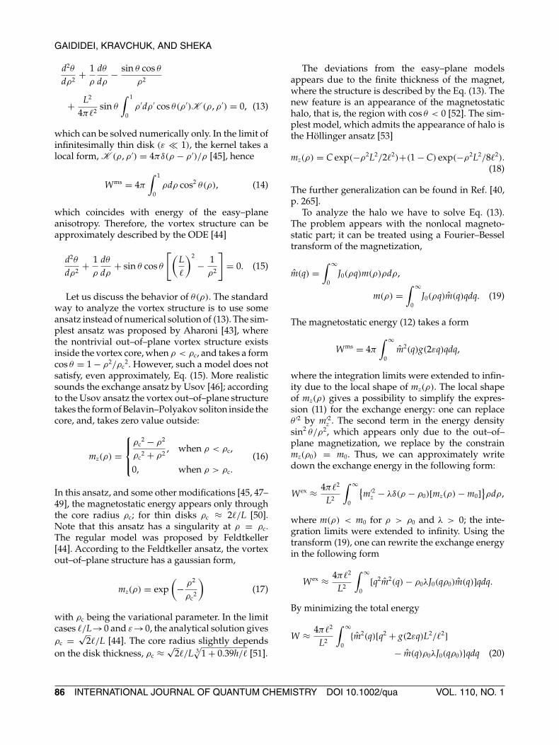
FIGURE 2. The vortex gyrofrequency � depending on the disk aspect ratio ε = h/2L. The dashed lines corresponds tothe Metlov’s ansatz following Ref. [62]: the curve (1) corresponds to the rigid ansatz (29), the curve (2) to the pole–freeansatz (30). The continuous line (3) is the theoretical calculation (34) using the image vortex ansatz. The dotted line (4)is the asymptote (35). The dashed–dotted line (5) is the magnon mode frequency according to Ref. [64], (6) the same byRef. [65]. The continuous line (7) is the OOMMF simulations data. The symbols (8) are the experimental data, see Ref.[4], symbols (9) are the experimental data by Ref. [65]. Symbols (10) corresponds to the experimental data by Ref. [66].[Color figure can be viewed in the online issue, which is available at www.interscience.wiley.com.]
Let us start with the case of small vortex displace-ments (s→0) and limit ourselves by the limit case of�(ε, 0). The last one takes a know form [47]
�(ε, 0) =∫ ∞
0dxg(ε, x)
[∫ 1
0ξdξ J1(xξ)
]2
,
g(ε, x) = 2εx − 1 + e−2εx
2x2ε2. (33)
One can see that for small vortex displacements theenergy has the harmonic law E ms = khR2/2, and therestoring force Fms = −kR with k = 4πε�(ε, 0).Therefore, the Thiele equation (24) results in avortex gyration, where the vortex precess with thefrequency
�(ε) = k|G| = 2ε�(ε, 0). (34)
This frequency corresponds to the frequency of thegyrotropic magnon mode on a vortex, which lies typ-ically in a sub-GHz range [62, 64, 66–68]. The depen-dence (34) is plotted by the curve (3) on Figure 2; itagrees well with experimental and simulations data.
In the case of very thin films (ε → 0), all calcu-lations can be done analytically, see Appendix: thegyrofrequency
�0 = 2ε�(0, 0) = 4ε
3π(2G − 1) ≈ 0.3531ε, (35)
which is in a good agreement with the result [66]:�0 ≈ 10ε/(9π) ≈ 0.3537ε.
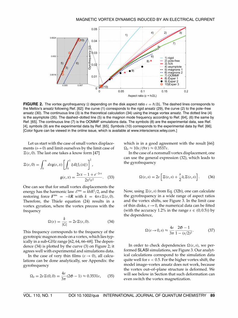
In the case of a nonsmall vortex displacement, onecan use the general expression (32), which leads tothe gyrofrequency
�(ε, s) = 2ε[�(ε, s) + s
2∂s�(ε, s)
]. (36)
Now, using �(ε, s) from Eq. (32b), one can calculatethe gyrofrequency in a wide range of aspect ratiosand the vortex shifts, see Figure 3. In the limit caseof thin disks, ε→0, the numerical data can be fitted(with the accuracy 1.2% in the range s ∈ (0; 0.5)) bythe dependence,
�(ε→0, s) ≈ 4ε
3π
2G − 11 − (s/2)2
. (37)
In order to check dependencies �(ε, s), we per-formed SLASI simulations, see Figure 3. Our analyt-ical calculations correspond to the simulation dataquite well for s < 0.5. For the higher vortex shift, themodel image–vortex ansatz does not work, becausethe vortex out–of–plane structure is deformed. Wewill see below in Section that such deformation caneven switch the vortex magnetization.
VOL. 110, NO. 1 DOI 10.1002/qua INTERNATIONAL JOURNAL OF QUANTUM CHEMISTRY 89

GAIDIDEI, KRAVCHUK, AND SHEKA
FIGURE 3. The vortex gyrofrequency �(ε, s)
normalized by �(ε, 0) as a function of the vortex shifts ≡ R/L. The continuous line (1) corresponds toanalytical caluclations by (36), (32b) for ε = 0, thedashed curve (2) is the approximate dependence (37).The continuous curves (3) and (5) correspond tocalculations for ε = 0.025 and ε = 0.1, respectively.Symbols are the SLASI simulations data: (4) correspondto ε = 0.025 for the spin lattice 2L = 40a0, h = a0, and = 1.4a0; symbols (5) correspond to ε = 0.1, 2L = 50a0,h = 5a0, and = 1.3a0. [Color figure can be viewed inthe online issue, which is available atwww.interscience.wiley.com.]
4. Current driven vortex dynamics
Let us discuss the effects of an electrical currenton the vortex dynamics in magnets. As we dis-cussed in the introduction, the current influences thespin dynamics of the magnet due to the spin–torqueeffect. There exist two main kinds of heterostruc-tures, where the spin-torque effect is observed [8]: acurrent-in-plane (CIP) structure, where both polar-izer and sensor layer are magnetized in plane and acurrent-perpendicular-to-the-plane (CPP) structure,where the sensor is in-plane magnetized, while thepolarizer is magnetized perpendicular to the plane.We consider the CPP heterostructure with a vortexstate sensor, which was proposed recently in Refs.37, 38.
It is well–known [12] that the spin torqueeffect causes a spin precession in a homogeneouslymagnetized particle. A similar picture also takesplace for the vortex state Heisenberg system [37],where the spin current, which is perpendicular tothe nanoparticle plane, mainly acts like an effec-tive perpendicular DC magnetic field. Recently, we
have shown [38] that the dipolar interaction cru-cially changes the physical picture of the process.The precessional vortex state [37] becomes unfa-vorable, because the dipolar interaction tries tominimize the edge surface magnetostatic charges,hence the magnetization at the dot edge is almostconserved [67].
We consider a pillar structure [37, 69, 70], inwhich the magnetization direction in the polarizer isaligned parallel to z (see Fig. 4). An electrical currentis injected in the polarizer, where it is polarized alongthe unit vector σ (which is collinear to z in our case).The sensor is a thin disk with a vortex ground state:the magnetization lies in the disk plane in the mainpart of the disk being parallel to the disk edge; how-ever in the disk center, the magnetization becomesperpendicular to the disk plane in order to preventa singularity in the magnetization distribution [40,58]. This perpendicular magnetization distributionforms the vortex core, which is oriented along z oropposite to z. Such a direction of the core magnetiza-tion is characterized by the vortex polarity (p = +1or p = −1, respectively). In the pillar stack, the thick-ness of the nonmagnetic layer (spacer) is much lessthan the spin diffusion length [69, 71], hence the spinpolarization of the current is conserved when it flowsinto the sensor.
The spin dynamics can be described by the LLGspin–lattice equations (2) with an additional spin–torque term Tn in the right hand side [12, 13] of thefollowing form:
Tn = jAω0
S + BSn · σ[Sn × [Sn × σ ]], (38)
FIGURE 4. Schematic of the CPP heterostructure usedfor the current induced vortex dynamics. [Color figurecan be viewed in the online issue, which is available atwww.interscience.wiley.com.]
90 INTERNATIONAL JOURNAL OF QUANTUM CHEMISTRY DOI 10.1002/qua VOL. 110, NO. 1
MAGNETIC VORTEX DYNAMICS INDUCED BY AN ELECTRICAL CURRENT
A = 4η3/2sp
3(1 + ηsp)3−16η3/2sp
, B= (1 + ηsp)3
3(1 + ηsp)3−16η3/2sp
.
(39)
Here j = Je/Jp is a normalized spin current, Je beingthe electrical current density, Jp = M2
S|e|h/�, e beingthe electron charge, and ηsp ∈ (0; 1) being the degreeof the spin polarization.
In the continuous limit one can use the LLG Eqs.(40) with an additional spin–torque term:
sin θ∂τφ = −δE
δθ− α∂τ θ , (40a)
− sin θ∂τ θ = −δE
δφ− α sin2 θ∂τφ + κ sin2 θ
1 + Bσ cos θ,
(40b)
where we introduced the normalized current κ =jσA. We are interested here by the influence of thehomogeneous spin torque T ∝ j · m only. Notethat such an approach is adequate if the magnetiza-tion does not change in the direction of the currentpropagation ( |∂zm| � 1); this is reasonable for theperpendicular current and thin nanodisks. However,if one applies a current in the direction of the diskplane, there appears a nonhomogeneous spin torqueT ∝ (j · ∇)m [72], which causes another mechanismof the vortex dynamics [32, 34, 39, 73, 74].
We start to analyze the spin torque effect with aquasi–uniform ground state, which is the in–planemagnetized disk. Under the influence of the spincurrent, the homogeneous ground state of the sys-tem changes: there appears a dynamical cone statewith the out-of-plane magnetization,
cos θh = σ
2B (√
1 + 4κBσ/α − 1) ≈ κ
α,
�h ≡ ∂τφ = cos θh, (41)
where the in–plane magnetization angle φ rotatesaround z–axes with a frequency �h. This state isstable only for |κ − αB| < α. Together with thisstate there is always the fixed point θh = 0 (resp.θh = π ), which is stable for κ − αB > α (resp.κ − αB > −α).
Let us discuss the vortex state nanodisk and studythe influence of the spin–torque effect in the vortexdynamics. The standard way to derive the effectiveequations of motions one can multiply Eq. (40a) by∇θ , Eq. (40b) by ∇φ, to add results and to inte-grate it by the sample volume. By incorporatingthe image–vortex ansatz (25) into this force balance
equation, one can finally obtain, similar to the Thieleequation (24):
G[ez × R] − 2πηR − 2π�(ε, s)R + FST = 0. (42a)
The last term in the right hand side, FST, is a spin–torque force:
FST = −κ
∫d2x
sin2 θ
1 + Bσ cos θ∇φ. (42b)
To treat this force analytically, we can neglect the B–term in denominator. Using the ansatz (25), one canapproximately calculate FST in the form [35, 36, 75]:
FST ≈ −κ
∫d2x∇φ = −πκq[R × ez]. (42c)
Using the polar coordinates for the vortex position,Z = (X + ıY) = Reı�, one can rewrite (42) in thefollowing form:
� = p�(ε, s) − 2πηRR
,RR
= −ηp� − 12
κp. (43)
Without the spin current term, the vortex stays at thedisk center, which is a ground state. This stability ofthe origin is provided by the damping. However, theloss of energy due to the damping can be compen-sated by the energy pumping due to the spin currentif the current exceeds a critical value, see below. Onecan see from Eq. (43) that the vortex position at ori-gin can be unstable when pκ < 0. The spin currentexcites a spiral vortex motion, which finally leads tothe circular limit cycle Z(τ ) = R0 exp(ıωτ) with thefrequency
ω = p�(ε, s0) = − κ
2η. (44)
The critical current can be easily estimated as fol-lows:
κcr = 2η�(ε), jcr = 2η�(ε)
A , (45)
where �(ε) = �(ε, s = 0), see (34). The spiral vortexmotion can be excited under the conditions: |j| > jcr
and pjσ < 0. Note that for small aspect ratios ε ≡h/2L � 1, one can use the approximation �(ε) ≈�0 = 4ε(2G − 1)/(3π), see (35), hence,
jcr ≈ 4αh(2G − 1)
3ALln
L
. (46)
VOL. 110, NO. 1 DOI 10.1002/qua INTERNATIONAL JOURNAL OF QUANTUM CHEMISTRY 91
GAIDIDEI, KRAVCHUK, AND SHEKA
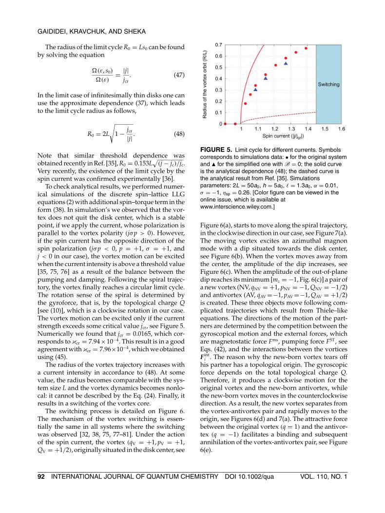
The radius of the limit cycle R0 = Ls0 can be foundby solving the equation
�(ε, s0)
�(ε)= |j|
jcr. (47)
In the limit case of infinitesimally thin disks one canuse the approximate dependence (37), which leadsto the limit cycle radius as follows,
R0 = 2L
√1 − jcr
|j| . (48)
Note that similar threshold dependence wasobtained recently in Ref. [35], R0 = 0.153L
√(j − jc)/jc.
Very recently, the existence of the limit cycle by thespin current was confirmed experimentally [36].
To check analytical results, we performed numer-ical simulations of the discrete spin–lattice LLGequations (2) with additional spin–torque term in theform (38). In simulation’s we observed that the vor-tex does not quit the disk center, which is a stablepoint, if we apply the current, whose polarization isparallel to the vortex polarity (jσp > 0). However,if the spin current has the opposite direction of thespin polarization (jσp < 0, p = +1, σ = +1, andj < 0 in our case), the vortex motion can be excitedwhen the current intensity is above a threshold value[35, 75, 76] as a result of the balance between thepumping and damping. Following the spiral trajec-tory, the vortex finally reaches a circular limit cycle.The rotation sense of the spiral is determined bythe gyroforce, that is, by the topological charge Q[see (10)], which is a clockwise rotation in our case.The vortex motion can be excited only if the currentstrength exceeds some critical value jcr, see Figure 5.Numerically we found that jcr = 0.0165, which cor-responds to κcr = 7.94×10⁻⁴. This result is in a goodagreement with κcr = 7.96×10⁻⁴, which we obtainedusing (45).
The radius of the vortex trajectory increases witha current intensity in accordance to (48). At somevalue, the radius becomes comparable with the sys-tem size L and the vortex dynamics becomes nonlo-cal: it cannot be described by the Eq. (24). Finally, itresults in a switching of the vortex core.
The switching process is detailed on Figure 6.The mechanism of the vortex switching is essen-tially the same in all systems where the switchingwas observed [32, 38, 75, 77–81]. Under the actionof the spin current, the vortex (qV = +1, pV = +1,QV = +1/2), originally situated in the disk center, see
FIGURE 5. Limit cycle for different currents. Symbolscorresponds to simulations data: • for the original systemand � for the simplified one with B = 0; the solid curveis the analytical dependence (48); the dashed curve isthe analytical result from Ref. [35]. Simulationsparameters: 2L = 50a0, h = 5a0, = 1.3a0, α = 0.01,σ = −1, ηsp = 0.26. [Color figure can be viewed in theonline issue, which is available atwww.interscience.wiley.com.]
Figure 6(a), starts to move along the spiral trajectory,in the clockwise direction in our case, see Figure 7(a).The moving vortex excites an azimuthal magnonmode with a dip situated towards the disk center,see Figure 6(b). When the vortex moves away fromthe center, the amplitude of the dip increases, seeFigure 6(c). When the amplitude of the out-of-planedip reaches its minimum [mz = −1, Fig. 6(c)] a pair ofa new vortex (NV, qNV = +1, pNV = −1, QNV = −1/2)and antivortex (AV, qAV =−1, pAV =−1, QAV = +1/2)is created. These three objects move following com-plicated trajectories which result from Thiele–likeequations. The directions of the motion of the part-ners are determined by the competition between thegyroscopical motion and the external forces, whichare magnetostatic force Fms, pumping force FST, seeEqs. (42), and the interactions between the vorticesF int
i . The reason why the new-born vortex tears offhis partner has a topological origin. The gyroscopicforce depends on the total topological charge Q.Therefore, it produces a clockwise motion for theoriginal vortex and the new-born antivortex, whilethe new-born vortex moves in the counterclockwisedirection. As a result, the new vortex separates fromthe vortex-antivortex pair and rapidly moves to theorigin, see Figures 6(d) and 7(a). The attractive forcebetween the original vortex (q = 1) and the antivor-tex (q = −1) facilitates a binding and subsequentannihilation of the vortex-antivortex pair, see Figure6(e).
92 INTERNATIONAL JOURNAL OF QUANTUM CHEMISTRY DOI 10.1002/qua VOL. 110, NO. 1

MAGNETIC VORTEX DYNAMICS INDUCED BY AN ELECTRICAL CURRENT
FIGURE 6. The temporal evolution of the vortex during the switching process by SLASI simulations: the upper rowcorresponds to the distribution of Sz spin components, the lower row corresponds to the in–plane spins around thevortex core. Isosurfaces Sx = 0 (black curve) and Sy = 0 (orange curve) are plotted to determine positions of vorticesand the antivortex. The simulation parameters: 2L = 100a0, h = 10a0, = 2.65a0, α = 0.01, σ = +1, ηsp = 0.26,j = −0.1. [Color figure can be viewed in the online issue, which is available at www.interscience.wiley.com.]
The three–body process for the Heisenberg mag-nets in a no-driving case is studied in details inRef. [82]. The internal gyroforces of the dip impartthe initial velocities to the NV and AV, which areperpendicular to the initial dip velocity and haveopposite directions. In this way, the AV gains thevelocity component directed to the center, wherethe V is moving. This new-born pair is a topologi-cally trivial Q = 0 pair, which undergoes a Kelvinmotion [83]. This Kelvin pair collides with the orig-inal vortex. If the pair was born far from V then thescattering process is semi–elastic; the new-born pair
is not destroyed by the collision. In the exchangeapproach, this pair survives, but it is scattered bysome angle [84]. Because of the additional forces(pumping, damping, and magnetostatic interaction),the real motion is more complicated and the Kevinpair can finally annihilate by itself. Another colli-sion mechanism takes place when the pair is borncloser to the original vortex. Then the AV can becaptured by the V and an annihilation with theoriginal vortex happens. The collision process isessentially inelastic. During the collision, the orig-inal vortex and the antivortex form a topological
FIGURE 7. The vortex dynamics under the switching by SLASI simulations for j = −0.1. Continuous curvecorresponds to the vortex trajectory before switching (p > 0), the dashed curve corresponds to the vortex trajectory afterthe switching (p < 0); at τ = 877 the vortex polarity is switched. [Color figure can be viewed in the online issue, which isavailable at www.interscience.wiley.com.]
VOL. 110, NO. 1 DOI 10.1002/qua INTERNATIONAL JOURNAL OF QUANTUM CHEMISTRY 93
GAIDIDEI, KRAVCHUK, AND SHEKA
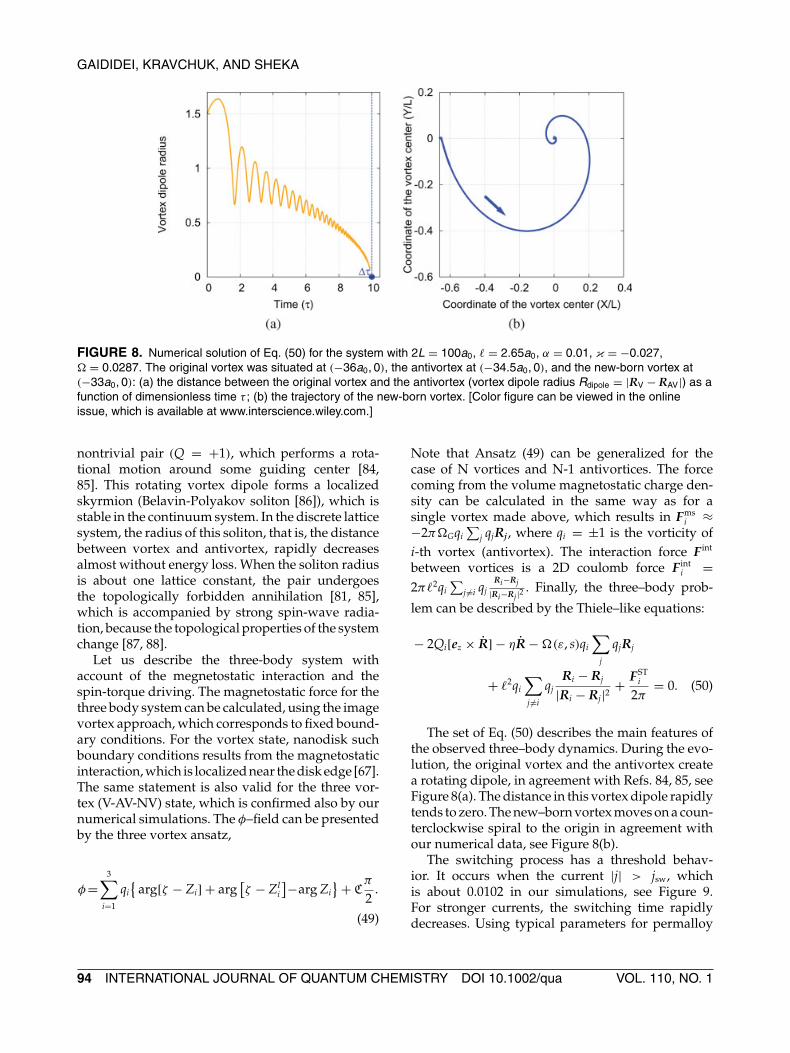
FIGURE 8. Numerical solution of Eq. (50) for the system with 2L = 100a0, = 2.65a0, α = 0.01, κ = −0.027,� = 0.0287. The original vortex was situated at (−36a0, 0), the antivortex at (−34.5a0, 0), and the new-born vortex at(−33a0, 0): (a) the distance between the original vortex and the antivortex (vortex dipole radius Rdipole = |RV − RAV|) as afunction of dimensionless time τ ; (b) the trajectory of the new-born vortex. [Color figure can be viewed in the onlineissue, which is available at www.interscience.wiley.com.]
nontrivial pair (Q = +1), which performs a rota-tional motion around some guiding center [84,85]. This rotating vortex dipole forms a localizedskyrmion (Belavin-Polyakov soliton [86]), which isstable in the continuum system. In the discrete latticesystem, the radius of this soliton, that is, the distancebetween vortex and antivortex, rapidly decreasesalmost without energy loss. When the soliton radiusis about one lattice constant, the pair undergoesthe topologically forbidden annihilation [81, 85],which is accompanied by strong spin-wave radia-tion, because the topological properties of the systemchange [87, 88].
Let us describe the three-body system withaccount of the megnetostatic interaction and thespin-torque driving. The magnetostatic force for thethree body system can be calculated, using the imagevortex approach, which corresponds to fixed bound-ary conditions. For the vortex state, nanodisk suchboundary conditions results from the magnetostaticinteraction, which is localized near the disk edge [67].The same statement is also valid for the three vor-tex (V-AV-NV) state, which is confirmed also by ournumerical simulations. The φ–field can be presentedby the three vortex ansatz,
φ=3∑
i=1
qi{
arg[ζ − Zi] + arg[ζ − ZI
i
]−arg Zi} + C
π
2.
(49)
Note that Ansatz (49) can be generalized for thecase of N vortices and N-1 antivortices. The forcecoming from the volume magnetostatic charge den-sity can be calculated in the same way as for asingle vortex made above, which results in Fms
i ≈−2π�Gqi
∑j qjRj, where qi = ±1 is the vorticity of
i-th vortex (antivortex). The interaction force F int
between vortices is a 2D coulomb force F inti =
2π 2qi∑
j �=i qjRi−Rj
|Ri−Rj |2 . Finally, the three–body prob-
lem can be described by the Thiele–like equations:
− 2Qi[ez × R] − ηR − �(ε, s)qi
∑j
qjRj
+ 2qi
∑j �=i
qjRi − Rj
|Ri − Rj|2 + FSTi
2π= 0. (50)
The set of Eq. (50) describes the main features ofthe observed three–body dynamics. During the evo-lution, the original vortex and the antivortex createa rotating dipole, in agreement with Refs. 84, 85, seeFigure 8(a). The distance in this vortex dipole rapidlytends to zero. The new–born vortex moves on a coun-terclockwise spiral to the origin in agreement withour numerical data, see Figure 8(b).
The switching process has a threshold behav-ior. It occurs when the current |j| > jsw, whichis about 0.0102 in our simulations, see Figure 9.For stronger currents, the switching time rapidlydecreases. Using typical parameters for permalloy
94 INTERNATIONAL JOURNAL OF QUANTUM CHEMISTRY DOI 10.1002/qua VOL. 110, NO. 1

MAGNETIC VORTEX DYNAMICS INDUCED BY AN ELECTRICAL CURRENT
FIGURE 9. Switching time as a function of the appliedcurrent. [Color figure can be viewed in the online issue,which is available at www.interscience.wiley.com.]
disks [37, 81] (A = 26 pJ/m, MS = 860 kA/m,α = 0.01), we estimate that the time unit 2π/ω0 = 33ps, the switching current density is about 0.1 A/µm2
for ηsp = 0.26 and 20 nm of a nanodot thickness. Thetotal current for a disk with diameter 200 nm is about10 mA.
5. Summary
As a summary, we have studied the magneticvortex dynamics under the action of an electrical cur-rent. The steady-state vortex motion (circular limitcycle) can be excited due spin–transfer effect abovea threshold current. This limit cycle results fromthe balance of forces between the pumping (dueto the spin-torque effect) and damping (due to theGilbert relaxation) [35, 75]. Recently, current-drivensubgigahertz oscillations in point contacts causedby the large-amplitude vortex dynamics wereobserved experimentally [36]. In particular, it wasobserved a stable circular orbit outside of the contactregion.
The switching of the vortex polarity takes placefor a stringer current. It is important to stress thatsuch a switching picture involving the creation andannihilation of a vortex-antivortex pair seems to bevery general and does not depend on the detailshow the vortex dynamics was excited. In particu-lar, such a switching mechanism can be induced bya field pulse [77–79], by an AC oscillating [80] orrotating field [81], by an in-plane electrical current(nonhomogeneous spin torque) [32, 74], and by aperpendicular current (our case, the homogeneous
spin torque) [35, 38, 75]. Our analytical analysis isconfirmed by numerical spin-lattice simulations.
Appendix
Let us calculate the gyrofrequency for the verythin disk. We start from the Eq. (33). In the limit caseε→0 one can write down:
�(0, 0) =∫ ∞
0dk
[∫ 1
0ξdξ J1(kξ)
]2
, (A1)
where the relation limε→0 g(ε, k) = 1 was used. Takinginto account that∫ ∞
0J1(ξx)J1(ξ
′x) dx
=
2πξ ′ [K(ξ ′/ξ)−E(ξ ′/ξ)], ξ ′ < ξ
2πξ
[K(ξ/ξ ′)−E(ξ/ξ ′)], ξ ′ > ξ ,
where K(x) and E(x) are elliptic integrals of the firstand second kinds respectively, it is easy to obtain�(0, 0) = 4
3π
∫ 10 [K(x) − E(x)]dx. After integration
by parts, where the property ddx E(x) = [E(x) −
K(x)]/x should be used, one can obtain the result�(0, 0) = 2
3π(2G − 1), with G = 1
2
∫ 10 K(x)dx ≈ 0.916
being the Catalan constant [89]. The correspondinggyrofrequency takes the form (35).
References
1. Guslienko, K. Y.; Novosad, V.; Otani, Y.; Shima, H.; Fukamichi,K. Phys Rev B 2001, 65, 024414.
2. Demokritov, S. O.; Hillebrands, B.; Slavin, A. N. Phys Reports2001, 348, 441.
3. Hillebrands, B.; Ounadjela, K. (Eds.) Spin Dynamics in Con-fined Magnetic Structures I, Topics in Applied Physics;Springer: Berlin, 2002; vol. 83.
4. Park, J. P.; Eames, P.; Engebretson, D. M.; Berezovsky, J.;Crowell, P. A. Phys Rev B 2003, 67, 020403.
5. Buess, M.; Hollinger, R.; Haug, T.; Perzlmaier, K.; Pescia,U. K. D.; Scheinfein, M. R.; Weiss, D.; Back, C. H. Phys RevLett 2004, 93, 077207.
6. Choe, S. B.; Acremann, Y.; Scholl, A.; Bauer, A.; Doran, A.;Stohr, J.; Padmore, H. A. Science 2004, 304, 420.
7. Thirion, C.; Wernsdofer, W.; Mailly, D. Nat Mater 2003, 2, 524.8. Zutic, I.; Fabian, J.; Sarma, S. D. Rev Mod Phys 2004, 76, 323.9. Marrows, C. H. Adv Phys 2005, 54, 585.
10. Tserkovnyak, Y.; Brataas, A.; Bauer, G. E. W.; Halperin, B. I.Rev Mod Phys 2005, 77, 1375.
VOL. 110, NO. 1 DOI 10.1002/qua INTERNATIONAL JOURNAL OF QUANTUM CHEMISTRY 95
GAIDIDEI, KRAVCHUK, AND SHEKA
11. Bader, S. D. Rev Mod Phys 2006, 78, 1.12. Slonczewski, J. C. J Magn Magn Mater 1996, 159, L1.13. Berger, L. Phys Rev B 1996, 54, 9353.14. Tsoi, M.; Jansen, A. G. M.; Bass, J.; Chiang, W. C.; Seck, M.;
Tsoi, V.; Wyder, P. Phys Rev Lett 1998, 80, 4281.15. Myers, E. B.; Ralph, D. C.; Katine, J. A.; Louie, R. N.; Buhrman,
R. A. Science 1999, 285, 867.16. Koo, H.; Krafft, C.; Gomez, R. D. Appl Phys Lett 2002, 81, 862.17. Kiselev, S. I.; Sankey, J. C.; Krivorotov, I. N.; Emley, N. C.;
Schoelkopf, R. J.; Buhrman, R. A.; Ralph, D. C. Nature 2003,425, 380.
18. Rippard, W. H.; Pufall, M. R.; Kaka, S.; Russek, S. E.; Silva, T. J.Phys Rev Lett 2004, 92, 027201.
19. Yamaguchi, A.; Ono, T.; Nasu, S.; Miyake, K.; Mibu, K.; Shinjo,T. Phys Rev Lett 2004, 92, 077205.
20. Krivorotov, I. N.; Emley, N. C.; Sankey, J. C.; Kiselev, S. I.;Ralph, D. C.; Buhrman, R. A. Science 2005, 307, 228.
21. Tulapurkar, A. A.; Suzuki, Y.; Fukushima, A.; Kubota, H.;Maehara, H.; Tsunekawa, K.; Djayaprawira, D. D.; Watanabe,N.; Yuasa, S. Nature 2005, 438, 339.
22. Özyilmaz, B.; Kent, A. D. Appl Phys Lett 2006, 88, 162506.23. Acremann, Y.; Strachan, J. P.; Chembrolu, V.; Andrews, S. D.;
Tyliszczak, T.; Katine, J. A.; Carey, M. J.; Clemens, B. M.;Siegmann, H. C.; Stohr, J. Phys Rev Lett 2006, 96, 217202.
24. Emley, N. C.; Krivorotov, I. N.; Ozatay, O.; Garcia, A. G. F.;Sankey, J. C.; Ralph, D. C.; Buhrman, R. A. Phys Rev Lett 2006,96, 247204.
25. Ishida, T.; Kimura, T.; Otani, Y. Phys Rev B 2006, 74, 014424.26. Jubert, P. O.; Klaui, M.; Bischof, A.; Rudiger, U.; Allenspach,
R. J Appl Phys 2006, 99, 08G523.27. Kläui, M.; Laufenberg, M.; Heyne, L.; Backes, D.; Rudiger, U.;
Vaz, C. A. F.; Bland, J. A. C.; Heyderman, L. J.; Cherifi, S.;Locatelli, A.; Mentes, T. O.; Aballe, L. Appl Phys Lett 2006, 88,232507.
28. Ozatay, O.; Emley, N. C.; Braganca, P. M.; Garcia, A. G. F.;Fuchs, G. D.; Krivorotov, I. N.; Buhrman, R. A.; Ralph, D. C.Appl Phys Lett 2006, 88, 202502.
29. Urazhdin, S.; Chien, C. L.; Guslienko, K. Y.; Novozhilova, L.Phys Rev B 2006, 73, 054416.
30. Houssameddine, D.; Ebels, U.; Delaet, B.; Rodmacq, B.;Firastrau, I.; Ponthenier, F.; Brunet, M.; Thirion, C.; Michel,J. P.; Prejbeanu-Buda, L.; Cyrille, M. C.; Redon, O.; Dieny, B.Nat Mater 2007, 6, 447.
31. Pribiag, V. S.; Krivorotov, I. N.; Fuchs, G. D.; Braganca, P. M.;Ozatay, O.; Sankey, J. C.; Ralph, D. C.; Buhrman, R. A. NatPhys 2007, 3, 498.
32. Yamada, K.; Kasai, S.; Nakatani, Y.; Kobayashi, K.; Kohno, H.;Thiaville, A.; Ono, T. Nat Mater 2007, 6, 270.
33. Bolte, M.; Meier, G.; Krüger, B.; Drews, A.; Eiselt, R.; Bocklage,L.; Bohlens, S.; Tyliszczak, T.; Vansteenkiste, A.; Waeyenberge,B. V.; Chou, K. W.; Puzic, A.; Stoll, H. Phys Rev Lett 2008, 100,176601.
34. Kasai, S.; Nakatani, Y.; Kobayashi, K.; Kohno, H.; Ono, T. PhysRev Lett 2006, 97, 107204.
35. Ivanov, B. A.; Zaspel, C. E. Phys Rev Lett 2007, 99, 247208.36. Mistral, Q.; van Kampen, M.; Hrkac, G.; Kim, J. V.; Devolder,
T.; Crozat, P.; Chappert, C.; Lagae, L.; Schrefl, T. Phys Rev Lett2008, 100, 257201.
37. Caputo, J. G.; Gaididei, Y.; Mertens, F. G.; Sheka, D. D. PhysRev Lett 2007, 98, 056604.
38. Sheka, D. D.; Gaididei, Y.; Mertens, F. G. Appl Phys Lett 2007,91, 082509.
39. Cowburn, R. P. Nat Mater 2007, 6, 255.40. Hubert, A.; Schäfer, R. Magnetic Domains: The Analysis of
Magnetic Microstructures; Springer–Verlag: Berlin, 1998.41. Stöhr, J.; Siegmann, H. C. Magnetism: From Fundamentals to
Nanoscale Dynamics, Springer Series in Solid-State Sciences;Springer-Verlag: Berlin/Heidelberg, 2006; vol. 152.
42. Stoner, E.; Wohlfarth, E. Philos Trans R Soc Lond 1948, 240,599.
43. Aharoni, A. J Appl Phys 1990, 68, 2892.44. Feldtkeller, E.; Thomas, H. Z Phys B: Condense Matter 1965,
4, 8.45. Guslienko, K. Y.; Novosad, V. J Appl Phys 2004, 96, 4451.46. Usov, N. A.; Peschany, S. E. J Magn Magn Mater 1993, 118,
L290.47. Metlov, K. L.; Guslienko, K. Y. J Magn Magn Mater 2002, 242–
245(Part 2), 1015.48. Scholz, W.; Guslienko, K. Y.; Novosad, V.; Suess, D.; Schrefl,
T.; Chantrell, R. W.; Fidler, J. J Magn Magn Mater 2003, 266,155.
49. Landeros, P.; Escrig, J.; Altbir, D.; Laroze, D.; d’Albuquerquee Castro, J.; Vargas, P. Phys Rev B 2005, 71, 094435.
50. Usov, N. A.; Peschany, S. E. Fiz Met Metal 1994, 78, 13 (inrussian).
51. Kravchuk, V. P.; Sheka, D. D.; Gaididei, Y. B. J Magn MagnMater 2007, 310, 116.
52. Ha, J. K.; Hertel, R.; Kirschner, J. Phys Rev B 2003, 67, 224432.53. Höllinger, R.; Killinger, A.; Krey, U. J Magn Magn Mater 2003,
261, 178.54. The Object Oriented MicroMagnetic Framework. Availabel at:
http://math.nist.gov/oommf/.55. Caputo, J. G.; Gaididei, Y.; Kravchuk, V. P.; Mertens, F. G.;
Sheka, D. D. Phys Rev B 2007, 76, 174428.56. Thiele, A. A. Phys Rev Lett 1973, 30, 230.57. Huber, D. L. Phys Rev B 1982, 26, 3758.58. Mertens, F. G.; Bishop, A. R. In Nonlinear Science at the Dawn
of the 21th Century; Christiansen, P. L.; Soerensen, M. P.; Scott,A. C., Eds.; Springer–Verlag: Berlin, 2000; p 137.
59. Guslienko, K. Y.; Novosad, V.; Otani, Y.; Shima, H.; Fukamichi,K. Appl Phys Lett 2001, 78, 3848.
60. Metlov, K. L. Two-dimensional topological solitons insmall exchange-dominated cylindrical ferromagnetic parti-cles, 2000, arXiv:cond-mat/0012146.
61. Guslienko, K. Y.; Metlov, K. L. Phys Rev B 2001, 63, 100403.62. Guslienko, K. Y.; Ivanov, B. A.; Novosad, V.; Otani, Y.; Shima,
H.; Fukamichi, K. J Appl Phys 2002, 91, 8037.63. Metlov, K. L. Two-dimensional topological solitons in soft
ferromagnetic cylinders, 2001, arXiv:cond-mat/0102311.64. Ivanov, B. A.; Zaspel, C. E. J Appl Phys 2004, 95, 7444.65. Zaspel, C. E.; Ivanov, B. A.; Park, J. P.; Crowell, P. A. Phys Rev
B 2005, 72, 024427.66. Guslienko, K. Y.; Han, X. F.; Keavney, D. J.; Divan, R.; Bader,
S. D. Phys Rev Lett 2006, 96, 067205.67. Ivanov, B. A.; Zaspel, C. E. Appl Phys Lett 2002, 81, 1261.
96 INTERNATIONAL JOURNAL OF QUANTUM CHEMISTRY DOI 10.1002/qua VOL. 110, NO. 1
MAGNETIC VORTEX DYNAMICS INDUCED BY AN ELECTRICAL CURRENT
68. Ivanov, B. A.; Zaspel, C. E. Phys Rev Lett 2005, 94, 027205.
69. Kent, A. D.; Ozyilmaz, B.; del Barco, E. Appl Phys Lett 2004,84, 3897.
70. Kent, A. D. Nat Mater 2007, 6, 399.
71. Xi, H.; Gao, K. Z.; Shi, Y. J Appl Phys 2005, 97, 044306.
72. Li, Z.; Zhang, S. Phys Rev Lett 2004, 92, 207203.
73. Shibata, J.; Nakatani, Y.; Tatara, G.; Kohno, H.; Otani, Y. PhysRev B 2006, 73, 020403.
74. Liu, Y.; Gliga, S.; Hertel, R.; Schneider, C. M. Appl Phys Lett2007, 91, 112501.
75. Liu, Y.; He, H.; Zhang, Z. Appl Phys Lett 2007, 91, 242501.
76. Sheka, D. D.; Gaididei, Y.; Mertens, F. G. In Electromagnetic,Magnetostatic, and Exchange-Interaction Vortices in Con-fined Magnetic Structures; Kamenetskii, E., Eds.; ResearchSignpost: India, 2008; p 59.
77. Waeyenberge, V. B.; Puzic, A.; Stoll, H.; Chou, K. W.;Tyliszczak, T.; Hertel, R.; Fähnle, M.; Bruckl, H.; Rott, K.; Reiss,G.; Neudecker, I.; Weiss, D.; Back, C. H.; Schütz, G. Nature2006, 444, 461.
78. Xiao, Q. F.; Rudge, J.; Choi, B. C.; Hong, Y. K.; Donohoe, G.Appl Phys Lett 2006, 89, 262507.
79. Hertel, R.; Gliga, S.; Fähnle, M.; Schneider, C. M. Phys RevLett 2007, 98, 117201.
80. Lee, K. S.; Guslienko, K. Y.; Lee, J. Y.; Kim, S. K. Phys Rev B2007, 76, 174410.
81. Kravchuk, V. P.; Sheka, D. D.; Gaididei, Y.; Mertens, F. G. JApplPhys 2007, 102, 043908.
82. Komineas, S.; Papanicolaou, N. In Electromagnetic, Magne-tostatic, and Exchange-Interaction Vortices in Confined Mag-netic Structures; Kamenetskii, E., Eds.; Research Signpost:India, 2008.
83. Papanicolaou, N.; Spathis, P. N. Nonlinearity 1999, 12, 285.84. Komineas, S.; Papanicolaou, N. Dynamics of vortex-
antivortex pairs in ferromagnets. In Electromagnetic, Magne-tostatic, and Exchange-Interaction Vortices in Confined Mag-netic Structures; Kamenetskii, E., Eds.; Research Signpost:India, 2008; p 335.
85. Komineas, S. Phys Rev Lett 2007, 99, 117202.86. Belavin, A. A.; Polyakov, A. M. JETP Lett 1975, 22, 24587. Hertel, R.; Schneider, C. M. Phys Rev Lett 2006, 97, 177202.88. Tretiakov, O.A.; Tchernyshyov, O. Phys Rev B 2007, 75, 012408.89. Gradshteyn, I. S.; Ryzhik, I. M. Table of Integrals, Series and
Products; Elsevir, Inc., 1980.
VOL. 110, NO. 1 DOI 10.1002/qua INTERNATIONAL JOURNAL OF QUANTUM CHEMISTRY 97