Magnetic Remanences Natural Remanent … a basaltic lava flow on Mt. Etna (Sicily) with the...
21
2013 SSRM 5/29/2013 1 Magnetic Remanences TRM (Thermoremanent Magnetization) TRM (P ti l Th tM ti ti ) pTRM (Partial ThermoremanentMagnetization) SR‐TRM (self‐reverse TRM) VRM (Viscous Remanent Magnetization) TVRM (Thermoviscous Remanent Magnetization) CRM (Chemical Remanent Magnetization) DRM (Detrital Remanent Magnetization) Natural Remanent Magnetization (NRM) 0 induced a J xH induced remanent J=J +J NRM= remanent magnetization present in a rock before any laboratory (artificial) treatments 0 induced a laboratory (artificial) treatments NRM= Process signal Geological processes during rock formation Recording process Geological processes after formation Remagnetization processes NRM is a function of several important parameters after formation processes Rock magnetism Recording media NRM = Primary + Secondary Component formed during initial rock formation Component(s) formed at some later time Types of NRM Type Process Thermoremanent Magnetization (TRM) Cooling through T c Primary NRM Detrital Remanent Magnetization (DRM) Deposition of magnetic grains Chemical Remanent Magnetization (CRM) Growth (alteration) of magnetic grains Type Process Viscous Remanent i i ( ) Long‐term exposure to H a Time Secondary NRM Magnetization (VRM) Isothermal Magnetization (IRM) Lighting strikes Exposure to large H a Chemical Remanent Magnetization (CRM) Growth (alteration) of magnetic grains Partial TRM (pTRM) Reheating below T c Field Volume temperature T hermor emanent M agnetization TRM is the magnetization produced by cooling from above the Curie temperature (T c ) in the presence of a magnetic field without any physical or chemical changes. la a flo s elded t ff deposits (ignimbrites) dikes gabbros anorthosites granites TRM is a thermally‐activated magnetization and is the form of remanent magnetism acquired by most igneous rocks. Tauxe, 2008 Basalt Welded tuff Mafic dike Mafic dike Granite Granite lava flows,welded tuff deposits (ignimbrites), dikes, gabbros, anorthosites, granites
Transcript of Magnetic Remanences Natural Remanent … a basaltic lava flow on Mt. Etna (Sicily) with the...

2013 SSRM 5/29/2013
1
Magnetic Remanences
TRM (Thermoremanent Magnetization)TRM (P ti l Th t M ti ti )pTRM (Partial Thermoremanent Magnetization)
SR‐TRM (self‐reverse TRM)VRM (Viscous Remanent Magnetization)TVRM (Thermoviscous Remanent Magnetization)CRM (Chemical Remanent Magnetization)DRM (Detrital Remanent Magnetization)
Natural Remanent Magnetization (NRM)
0induced aJ x Hinduced remanentJ = J + JNRM= remanent magnetization
present in a rock before any laboratory (artificial) treatments 0induced alaboratory (artificial) treatments
NRM=
Process signal
Geological processes during rock formation
Recording process
Geological processes after formation
Remagnetization processes
NRM is a function of several important parameters
after formation processes
Rock magnetism Recording media
NRM = Primary + SecondaryComponent formed during initial rock
formation
Component(s) formed at some later time
Types of NRM
Type Process
Thermoremanent Magnetization (TRM)
Cooling through Tc
Primary NRM Detrital Remanent Magnetization (DRM)
Deposition of magnetic grains
Chemical Remanent Magnetization (CRM)
Growth (alteration) of magnetic grains
Type Process
Viscous Remanent i i ( )
Long‐term exposure to Ha Time
Secondary NRMMagnetization (VRM)
Isothermal Magnetization (IRM)
Lighting strikesExposure to large Ha
Chemical Remanent Magnetization (CRM)
Growth (alteration) of magnetic grains
Partial TRM (pTRM) Reheating below Tc
Field
Volume
temperature
Thermoremanent MagnetizationTRM is the magnetization produced by cooling from above the Curie temperature (Tc) in the presence of a magnetic field without any physical or chemical changes.
la a flo s elded t ff deposits (ignimbrites) dikes gabbros anorthosites granites
TRM is a thermally‐activated magnetization and is the form of remanent magnetism acquired by most igneous rocks.
Tauxe, 2008
Basalt Welded tuff Mafic dikeMafic dike GraniteGranite
lava flows, welded tuff deposits (ignimbrites), dikes, gabbros, anorthosites, granites

2013 SSRM 5/29/2013
2
TRMLet’s do the following experiments on identical samples containing SD grains
1. Give a sample a TRM by cooling from Tc to room temperature in Ba= 50μTp y g c p a μ2. Give a sample an isothermal remanent magnetization (IRM) in the same field
at room temperature without any heating Observations
Intensity of Magnetization: JTRM>>JIRM
Field needed to reduce J to zeroJ : B B (50μT)JIRM: BBa (50μT)JTRM: B Brc>>Ba
Brc (coercivity of remanence) ~50‐100 mT
At surface temperatures , TRM can be stable over geologic time and resistant to remagnetization by the geomagnetic field (Brc>>Be)
Some Experimental Properties of TRM
• JTRM is parallel to B0
• JTRM B0
Weak‐Field TRM: B0<<Bcr
Field dependence
SD titanomaghemites
TRM 0• JTRM decreases with particle size• Equivalence of blocking and
unblocking temperatures in heating and cooling (TB=TUB)
~d‐1
Dunlop and Özdemir, 1997,2002
Grain size dependenceThermal demagnetization of
1‐mT TRM (TB=TUB)
Agreement of directions of
JTRM is parallel to B0
gthermoremanent magnetizationin a basaltic lava flow on Mt. Etna (Sicily) with the direction of the geomagnetic field during eruption of the lava (based upon data from Chevallier, 1925).
Lowrie, 1998
Theoretical Model of TRM for SD grainsNéel (1949) established the theoretical basis for understanding thermally‐activated magnetization
Very small changes in v, T, or H can produce very large changes in
Starting Assumptions:
Consider an assemblage of identical, non‐interacting, SD grains.
The magnetic moment of an SD grain can point in one of two equal d i di i ( i i l i )
y g , , p y g grelaxation times
and opposite directions (uniaxial anisotropy).
Above TB, the magnetic moment will flip rapidly between these two antiparallel directions.

2013 SSRM 5/29/2013
3
Néel Model for SD Thermoremanent MagnetizationTwo‐state particle (parallel or antiparallel to H0 )
E2= +0vMsH0, n‐H0
The energy difference between these two states will create a preference for occupying the state where m is parallel to HE1= ‐0vMsH0, n+
0
H0=0 H00 v=particle volume
parallel to H.
BUT, thermal energy (kT) acts as a randomizing influence
Energy partition functionB lt b bilit
N= total number of particles N=n++n‐
1 2
1 2 1 2
/ /
/ / / /
E kT E kT
E kT E kT E kT E kT
n e n eN N
Boltzmann probability
0 02 vM /1
2
sH kTn en
1 2 1 2/ / / /E kT E kT E kT E kTN e e N e e
TRM=frozen high‐temperature partition between micromagnetic states
Magnetization
Néel Model for SD Thermoremanent Magnetization
20 0
2
vM( ) 1 tanh( ),( ) 1
bs
bs
Hn nM T e b bM T n n e kT
1.0
The bias of magnetic moments (degree of -0.5
0.0
0.5
tanh
(b)
( )=M (T)tanh( )sM T b
Equilibrium Magnetization for a given v, T, and H
Maximum M ti ti moments (degree of
alignment) along H0
‐1 tanh(b) ‐ 1‐ b
-1.0-4 -3 -2 -1 0 1 2 3 4
b
Magnetization
1tanh( )
1 1b b
bb
T = Tc
T = TB
paramagnetism
superparamagnetism unblocked
e de
crea
sing
0
shortEB~mBearrthB th ~ 50 μT
Néel made a critical assumption
T>TB grain assembly in equilibrium with T, HM=M
Néel Model for SD TRM
T = T0
blocked stable
Tem
pera
ture
EB
Bearth 50 μT
Very longEB~mBcrBcr~ 50 mT
M=Meq
T<TB magnetization is blocked (frozen) at TBno further redistributionBias is fixed at TB
Weak‐field TRM (acquired in Be)
Cartoon of TRM blocking in SD GrainsvM ( )TRM(T ) =M (T )tanh s B e
B r BB
T BkT
T=TB
Néel Model for SD Thermoremanent Magnetization
vM ( )TRM(T ) =M (T )tanh s B eB r B
B
T BkT
At blocking temperatureDirection is frozen in (bias)Only magnitude changes with T
0vM ( )TRM(T ) =M (T )tanh s B e
o rB
T BkT
y g g
magnitude bias
This bias will be “locked” in as the assemblage cools through its blocking temperature to T0
The only variable that will change during cooling is the saturation magnetization.

2013 SSRM 5/29/2013
4
Let’s work through an l
Spherical particle with diameter=40 nmTB = 550 ˚C (823 K)H = 100 μT (This is ~2x the modern field)
Néel Model for SD Thermoremanent Magnetization
Degree of Alignment at TB
example:
Use these values here:
H = 100 μT (This is ~2x the modern field)Ms of magnetite at 550˚C = 140 kA/mv = 3.35 x 10‐23 m3
b = 0.041 tanh(0.041) = 0.041
vMs eBbkT
This is an incredibly small degree of alignment!
tanh( ) 4%n nbN
Néel Model for SD Thermoremanent Magnetization
0vM ( )TRM(T ) =M (T )tanh s B e
o rB
T BkT
Bias is always small, soTanh(b)b
0
0
vM ( )TRM(T ) M (T )
vM ( )TRM(T ) M (T )
s B eo r
B
s Bo r e
B
T BkT
T BkT
“constant” External field d lte
nsity
during cooling at TB
Be
TRM int TRM intensity is linearly
proportional to the external field applied at TB (for small B)
Theoretical Model of TRM for SD grains
0vM ( )TRM(T ) =M (T )tanh s B e
o rB
T BkT
This model also assumes that all the SD grains in the assemblage are identical with only one blocking temperature.
Real rocks have a wide variety of sizes and shapes that produce a range of TB.
To visualize TRM acquisition for distributions of TB, we can use v‐Hc diagram q , g
990.Stable SD
(v,Hc)
Butle
r, 19
SPMunstable
( ) ( )c sH T NM T
Just below the Curie temp. most grains behave superparamagnetically (low Hc), with relaxation times shorter than 100 s.
As the assemblage cools, Hc increases, the relaxation time of a fraction of the grains becomes longer than 100 s (SP grains become SD grains).

2013 SSRM 5/29/2013
5
Generalizing the Model
OK, so this model is pretty good in that it explains the essentials of TRM acquisition, but it assumes uniaxial anisotropy axes are all aligned. (In real rocks, ferromagnetic grains and their easy axes are distributed randomly).
To deal with this reality, we can set the aligning energy for an individual particle as:
E = m∙B = mB cosθ , where θ is the angle between the easy axis and B.
Final TRM intensity if found by integrating over all orientations
This leads to a more complicated expression, but the essence of the physics is the same.
/20
0
0 0 0
vM costanh cos sin
vM ( )( ) ( )3
ss
s Br
B
BTRM M dkT
TTRM T M T BkT
orientations
We can actually “see” the distribution of TB’s in a sample during thermal demagnetization.
Partial Thermoremanent Magnetization
Butler, 1990.
Thermal demagnetization spectra
pTRM
Thermal demagnetization spectra for a basalt sample containing two TRM components with different blocking temperatures
Stacey and Banerjee, 1974
Partial Thermoremanent MagnetizationA rock’s total TRM can be viewed as portions acquired in distinct temperature intervals, or windows of blocking temperatures.
pTRM(T2,Tc,0)=0tanh(0)=0
pTRM(T0,T1,0)=0tanh(0)=0
T0 T1 T2 Tc
B0= 0 B00 B0= 0
Only those SD grains with T1 <TB <T2 will acquire a TRM
pTRM(T1,T2,B0)
Th lli (1938) d t t d 3 i t l l i TRM
tanh(0)=0tanh(0)=0
Thellier (1938) demonstrated 3 experimental laws governing pTRMs
Law of AdditivityLaw of IndependenceLaw of Reciprocity

2013 SSRM 5/29/2013
6
Partial Thermoremanent Magnetization
PTRMs are only influenced by the magnetic field that is present during cooling through their respective TBinterval.
Law of Additivity
pTRM3
pTRM4
pTRM5
TRM
If you add up each of the PTRMs you should arrive at the total TRM.
Total TRM =pTRM1 + pTRM2 + pTRM3+…
Blocking temperature spectrum can be decomposed into non‐overlapping fractions
Butler, 1990.
pTRM1
pTRM2pTRM6
pTRM7pTRM8
overlapping fractions
Partial Thermoremanent Magnetization
A particular pTRM is independent in direction & intensity from any other
Law of Independence
pTRM produced over a different temperature interval.
While this may seem like an obvious statement, it is only true for SD grains.
This “Law” fails spectacularly for MD grains and certain kinds of PSD grains.
Tauxe, 2008.
Partial Thermoremanent Magnetization
The grains that define a particular pTRMs have unblocking temperatures (TUB) that are identical to their blocking temperature (TB) .
Law of Reciprocity
pTRM(T1,T2,B0) is thermally demagnetized over precisely the (T1,T2) interval when heated in zero field
While this may seem like an obvious statement, it is only true for SD grains.
Tauxe, 2008.
This “Law” fails spectacularly for MD grains and certain kinds of PSD grains.
Thermal DemagnetizationHeating samples to elevated temperatures (T<Tc)Cooling to room‐temperature in zero magnetic field
All grains TB<Tdemag become unblockedB demag(Acquires a pTRM=0 upon cooling in H=0)
Grains with short relaxation times (low TB) are likely to pick up secondary NRMs (unstable NRM)
These grains get demagnetized first before grains with long relaxation times (stable NRM)

2013 SSRM 5/29/2013
7
Partial Thermoremanent Magnetization
pTRM(400,500,B0)
Thermal demagnetization pTRM acquisition
Dunlop and Özdemir, 1997
Partial Thermoremanent Magnetization
An example of the Laws of Additivity, Independence, and
Initial TRM: TRM(T0,TC,B0)Rock is reheated to Tr (T0<Tr<Tc) in B*
A rock can record more than one episode of TRM acquisition.
We can “see” these two magnetization components in the lab as we thermally demagnetize a sample.
Reciprocity.
pTRMs with TB<Tr reset to new B*pTRMs with TB>Tr retain original TRM vector
Welded, pyroclastic ash deposits intruded by basaltic dikes.
http://creminer.fc.ul.pt/ingles/Workshop_LA_Horta_2006.htm
We can strip away pTRMs in grains with low TB while higher TB grains are unaffected
This is a fundamental element of paleomagnetic studies.
Grain Size Dependence of TRM
This model also assumes that
0vM ( )TRM(T ) =M (T )tanh s B e
o rB
T BkT
This model also assumes that all grains in the assemblage are SD.
Real rocks have a wide variety of sizes and shapes, and usually only a small fraction are truly SD.
SDSD
PSDPSD
Most grains are PSD or MD.
What do we know about how PSD and MD acquire TRM?
MDMD
This plot shows how different sizes of magnetite grains acquire TRM in a 0.1 mT (1 Oersted) field.
Dunlop & Özdemir, 1997
Grain Size Dependence of TRM
PSD Grains
TRM efficiency starts to decrease relative to SD grains. SDSDto SD grains.
PSD grains do acquire TRMs that are stable in time and resistant to demagnetization by later magnetic fields.
The physics of PSD TRM acquisition is not well understood, but the basic concept seems to be the same.
SDSD
MDMD
PSDPSD
NOTE! PSD grains do not always follow the Law of Additivity, Independence, and reciprocity.

2013 SSRM 5/29/2013
8
Grain Size Dependence of TRM
MD
TRM efficiency is very low relative SDSD
to SD grains.
TRM acquired by MD tends to decay rapidly with time (viscous magnetization). MDMD
PSDPSD
Dunlop & Özdemir, 1997
SD and PSD grains typically carry stable TRM, while MD grains carry a component acquired long after cooling.
Grain Size Effects: Extrusive vs. Intrusive Rocks Extrusive Igneous: Rapidly cooled volcanic rocks have a grain size distributions peaking at d < 10 µm, mainly in the SD and PSD size range.
Thus volcanic rocks are often possess strong and stable TRMs Typical intensitiesstrong and stable TRMs. Typical intensities for a basalt flow are 1 A m‐1
There is a small fraction of MD grains, but their effect is minimized.
Intrusive igneous: Grain size distributions peak at larger diameters and a majority of grains are MD.
In general extrusive volcanic
extrusive
Intrusive
The intensity of stable TRM in intrusive igneous rocks is usually much smaller than in extrusive volcanic rocks.
Secondary components carried by the MD grains can dominate the magnetization.
In general, extrusive volcanic rocks are preferred to intrusive rocks for paleomagnetic analyses.
Grain Size Effects: Intrusive Rocks: Felsic vs. MaficMafic rocks (gabbros, anorthosites) are more likely to carry a stable TRM than felsic rocks (granites, diorites).
Mafic melts have higher Fe and Ti contents and titanomagnetite grains in h k f l d hi h l i i ldthese rocks frequently undergo high temperature exsolution yields an effective magnetic grain size less than that of the original FeTi oxide grain.
Ilmenite lamellae (bright) within magnetite (grey)
5 µm
Magnetite inclusions exsolved in plagioclase. (Feinberg et al., 2006)
Mafic rocks are also more likely to contain silicate minerals with exsolved grains of magnetite and/or hematite/ilmenite.
Grain Size Dependence of pTRMSD grains
sharp TB and TB=TUB
PSD and MD grainsPSD and MD grainsindividual walls can have different TB’sSet of TB’s can change when a wall moves because of changes in HDOne MD grain can have a distribution of TB’s
Thermal demagnetization spectrum b d h
Stepwise thermal demagnetization of pTRM broadens with increasing grain size
PSD and MD grains demagnetization starts below TBextend beyond TB up to TClow‐T and high‐T pTRM tails
p g p(acquired by heating at TB for 3.5 hr) produced over narrow TB ranges in magnetites for SD (405°C), PSD(375°C), and MD (350°C) grain sizes
Dunlop and Özdemir, 2000

2013 SSRM 5/29/2013
9
Field Dependence of TRM
00
vM ( )TRM(T ) =M (T )tanh s Bo r B
B
T B T TkT
TRM intensity reaches saturation when B0>4kT/vMs
The intensity of a TRM acquired in a weak field is proportional to the field strength.
There is a linear relationship.
0 sFor 50 nm cube of magnetite at TB=500°C
Bsat1.5 mT
p
Range of Modern Field Values Dunlop & Özdemir, 1997
0vM ( )TRM(T ) M (T ) s B
o r eB
T BkT
“constant”
PaleointensityThe linearity of TRM acquisition in weak fields and pTRM Laws of Additivity, Independence, and Reciprocity also serve as the foundation of most paleointensity methods.
0vM ( )s B
B
TkT
Magnetization process in MD grain
Wall displacement and Hysteresis in 2‐domain grain
2 20 0( ) 2 /T w d H w s a sE x E E E E AM H x NAM x a
Total Energy of TD grain
994
Ew= fluctuating wall energyx=wall displacementA= domain wall areaN=demagnetizing factors
xM Ma
At equilibrium, ET(x) is a minimum if dET/dx =0: 0 02 ( ) 2ws a s i
dE AM H NM AM Hdx
Dunlop
and
Xu, 1
Internal field (Hi) needed to displace wall i i E t B i i i it
12
wc
dEhAM d
For small H0: walls are pinned near local energy minima (A,C)For larger H0: wall is displaced towards max. slope in Ew (D,E)
Assume Ew(x) is sinusoidal
over maximum in Ewall at B is microcoercivity max02csAM dx
Increasing Fields: parabolas are tilted to the right by the field energy, moving wall from one LEM state to another
Decreasing Fields: wall is pinned in a different
2 20 0( ) 2 /T w d H w s a sE x E E E E AM H x NAM x a
1997
Decreasing Fields: wall is pinned in a different set of LEM states
H00: wall is trapped away from center of grain (x=0)producing a net remanence (IRM)
Dunlop
and
Özdem
ir,
A i i i f TRM i 2D G i
Total energy ET(x) as a function of wall displacement in increasing (down arrows) and decreasing (up arrows) fields
Acquisition of TRM in 2D GrainSchmidt Model (1973)
( ) cos(2 / )pw sE BM T x B=constantℓ=wave length of stress fieldp=anisotropy exponent (p=3 ,magnetoelastic)
2013 SSRM 5/29/2013
10
Experimental and theoretical (dashed) dependences of TRM intensity on applied magnetic field Ho for SD and MD magnetite and hematite.
HematiteSmall demagnetizing fields in hematite
MD TRM
Small demagnetizing fields in hematite (low Ms ) allow large wall displacements towards saturation (Ms)
When H0 is removed walls remain displaced (Hd ~0), Mr~Ms
MagnetiteSelf demagnetization (due to high Ms) drive walls back from saturation
Dunlop and Özdemir, 2007
drive walls back from saturation
When H0 is removed, Mrs<< Ms
Self‐demagnetization is the reason why TRM saturates for MD magnetite in fields three orders of magnitude larger than for MD hematite
Dependence of TRM intensity on grain size for magnetite and hematite
Dunlop DJ and Arkani‐Hamed J (2005) Magnetic minerals in the Martian crust. Journal of Geophysical Research 110: E12S04 (doi:10.1029/ 2005JE002404).
Surprisingly, in hematite, TRM intensity is larger in coarse grained MD particles (> 1‐1000 μm ) than in fine grained SD particles.
TRM‐grain size relationship that is exactly opposite to that found in magnetite and titanomagnetite
Summary of TRM Properties
• Remanence of an assemblage of randomly oriented SD/PSD particles – JTRM is parallel to B0
– JTRM B0
Weak‐Field TRM: B0<<Bcr
JTRM B0• pTRM laws of Additivity, Independence, and Reciprocity
– Equivalence of blocking and unblocking temperatures in heating and cooling (TB=TUB)
– Sharpness of blocking temperature responsible for simplicity of laws• JTRM decreases with particle size• MD grains
– TRM efficiency is very low relative to SD grains. y y g– One TB produces a spectrum of TUB’s– pTRM produced at TB<TC needs to be heated to TC to fully remove it
Viscous Remanent Magnetization
VRM is the magnetization that is gradually acquired during prolonged exposure to magnetic fields.
VRM is typically acquired long after a rock is formed.
It is often viewed as a secondary, unwanted magnetization that is a source of noise.
VRMs can effect igneous, sedimentary, and metamorphic rocks...
Basalt Welded tuff Mafic dikeMafic dike GraniteGranitesandstone Gneiss

2013 SSRM 5/29/2013
11
Single Domain VRM
Stable NRM As time increases unblocking window moves across the grain distribution
The initial magnetization is gradually replaced by a viscous remanent magnetization (VRM) in the direction of H0
200vHK HM
Butler, 1992
000
vHln( ) 12
K s
K
HMf tkT H
Magnetic Relaxation and VRMTauxe, 2007
/0( ) ( ) t
eq eqM t M M M e
Commonly observed that VRM does not follow a simple exponential dependence but instead a logarithmic dependence
A synthetic sample of 2 µm dispersed magnetite grains sitting in a 330 µT field
S=Viscosity Coefficient
log( )VRM S t
Logarithmic dependence comes from a distribution of grain sizes and shapes f(v,HK) producing a distribution of relaxation times
Stacey & Banerjee, 1974
VRM acquisition (H0) VRM decay (H=0)
The viscosity coefficient is strong function of temperature
Dunlop and Özdemir, 2007
Examples of VRM acquisition
M (x10
‐2A/
m)
Experiments also show th t VRM b i d
igneous
metamorphic
VRM for a ocean floor basalt showing non‐log time behavior (Moskowitz, 1985).
VRM that VRM can be acquired
in a non‐log fashion.
sedimentary
Dunlop and Özdemir, 2007VRM in pelagic limestone samples (Lowrie and Heller, 1982).

2013 SSRM 5/29/2013
12
superparamagnetic << s M=meq
viscous s M=Slog(t)
Stable SD >> s M=0.5Ms
Time dependent Magnetization
VRM acquisition for PSD & MD grains
VRM is acquired through thermal activation of domain walls.
Thermal energy allows domain walls (or wall sections) to overcome local energy barriers
Butler, 1992
sections) to overcome local energy barriers.
This thermal energy augments the interaction energy between the applied field and the magnetization of the grain, resulting in increased magnetization in the direction of the applied field.
MD grains
Grains with low coercivity rapidly acquire VRM and often dominate the overall VRM.This relationship between coercivity and VRM is exploited by paleomagnetists during demagnetization, in an effort to remove VRM components.
Acquisition of Thermoviscous Remanent Magnetization (TVRM)
Rocks are often reheated by a variety of geologic processes:
Local metamorphism (nearby dike or sill), regional metamorphism (large‐scale igneous intrusions) burial metamorphism tectonic(large‐scale igneous intrusions), burial metamorphism, tectonic metamorphism, etc...
How do prolonged periods of reheating below a mineral’s Curie temperature effect a rock’s ability to retain a primary magnetization?
How do prolonged periods of reheating below a mineral’s Curie temperature effect a rock’s ability to acquire a VRM?
To explore these questions, let’s imagine a population of identical SD grains. Their relaxation time (as a function of temperature) is given by the classic Néel equation:
0
0
( ) ( )1 exp2
s KvM T H Tf kT
Acquisition of TVRM
0v ln( ( ) )constant2 ( ) ( )
o
s K
T T fk M T H T
Assemblage of identical SD grains (v=constant)
The population of SD grains will have a relaxation time τ1 at temperature T1 and τ2 at temperature T2.
Because the left side of the equation is constant, the relationships between parameters T1 and T2 can be written as:
( ) ( )s K
1 1 2 2
1 1 2 2
ln( ) ln( )( ) ( ) ( ) ( )
o o
s K s K
T f T fM T H T M T H T
Time‐temperature relationship

2013 SSRM 5/29/2013
13
Acquisition of TVRMMagnetite: HK values for SD particles are dominated by shape anisotropy:
ΔN is the difference in the internal
( ) ( )K sH T NM T
Dunlop
& Özdem
ir, 2007
demagnetizing factor between short and long axes of the SD grain.
Hematite: Hk values for SD particles are dominated by magnetocrystalline anisotropy, which are more sensitive to temperature:
3( ) ( )K sH T DM T
Normalized Ms(T ) dependences for five common magnetic minerals
where D is a proportionality constant that is independent of temperature.
( ) ( )nK sH T aM T
General Case (n=1,2,3.., a=constant):
Acquisition of TVRM
Using the definition of HK(T)M n(T) in the blocking equation above:
1 1 2 2
1 1 2 2
ln( ) ln( )( ) ( ) ( ) ( )
o o
s K s K
T f T fM T H T M T H T
Using the definition of HK(T)Ms (T) in the blocking equation above:
which gives
1 1 2 21 1
1 2
ln( ) ln( )( ) ( )
s
o on n
s
T f T fM T M T
1 1 2 2ln( ) ln( )o oT f T f 1 1 2 2ln( ) ln( )o oT f T f
Magnetite (n=1) Hematite (n=3).
Note: ΔN and D are constants and cancel out in these calculations.
2 21 2( ) ( )
s sM T M T 4 41 2( ) ( )
s sM T M T
Acquisition of TVRM
‐T diagrams, are useful ways to visualize this relationship.
1 1 2 2ln( ) ln( )o oT f T f
for magnetite.
Each one of these lines is alocus of points in –TB space
2 21 2( ) ( )
s sM T M T
Pullaiah et al., 1975
Point 1 shows a population of SD grains in τ‐TB space that has a relaxation time of 10 Ma at 260˚C.
Translation: after 10 Ma, these SD grains would acquire a significant VRM.
that activate the same grain
Acquisition of TVRM
‐T diagrams, are useful ways to visualize this relationship.
1 1 2 2ln( ) ln( )o oT f T f
for magnetite.
2 21 2( ) ( )
s sM T M T
Pullaiah et al., 1975
Point 2 shows a population of SD grains in τ‐TB space that has a relaxation time of 30 minutes at 400˚C.
Point 1 and 2 lie on the same nomogram.
After 30 minutes at 400˚C, these grains would acquire the same VRM acquired over 10 Ma at 260˚C.

2013 SSRM 5/29/2013
14
Acquisition of TVRM: Paleothermometry
‐T, are useful ways to visualize this relationship.
ln( ) ln( )B n o UB L oT f T f 2 2( ) ( )s
B n o UB L o
B s UBM T M T
This has BIG implications!
TVRM i d b k d i 10 M i l
(TB,N) natural(geological) conditions(TUB,L) laboratory conditions
Pullaiah et al., 1975TVRM acquired by a rock during a 10 Ma interval can be unblocked by heating a sample in a lab for 30 minutes in zero magnetic field.
This heating would reset the grains’ magnetization to zero, even though we didn’t heat to the Curie temperature.
Acquisition of TVRM
‐T diagrams, are useful ways to visualize this relationship.
ln( ) ln( )B n o UB L oT f T f
Now look at points 3 and 4.
The size and shape of these SD grains are different from the SD grains at points 1 and 2. But both populations of grains have the same value of v/2k.
2 2( ) ( )s B s UBM T M T
Pullaiah et al., 1975Point 3 shows a population of SD grains in τ‐TB space that has a = 10 Ma atT= 520˚C.
Point 4 shows a population of SD grains in τ‐TB space that has = 30 min at T=550˚C.
This is another way of showing the rapid increase in relaxation time with decreasing temperature for grains with TB close to the Curie temperature.
aiah
et a
l., 1975
The ‐T diagram is broadly split into A and B regions.
Grains in region A have laboratory blocking temperatures within 100˚C of the Curie temperature, TC.
Th i i t t t tti
PullaThese grains are resistant to resetting
of magnetization, except by heating to temperatures near TC.
Grains in region B have laboratory blocking temperatures distributed over wide intervals below TC.
mir, 1997
These grains are more susceptible to VRM or TVRM acquisition, and are generally too unstable to retain a primary NRM. Du
nlop
and
Özde
Acquisition of TVRM
Pullaiah et al., 1975
ln( ) ln( )T f T f ln( ) ln( )T f T f
There are differences between the unblocking diagrams for magnetite and hematite.
1 1 2 22 2
1 2
ln( ) ln( )( ) ( )
s
o o
s
T f T fM T M T
1 1 2 2
4 41 2
ln( ) ln( )( ) ( )
s
o o
s
T f T fM T M T

2013 SSRM 5/29/2013
15
Acquisition of TVRM
Pullaiah et al., 1975These diagrams indicate that primary NRMs should survive heating through the greenschist metamorphic facies (300‐500˚C), but not through the amphibolite facies (550‐750˚C).
Grains in region A should have magnetizations that are blocked at approximately the same time as radiogenic argon is trapped in hornblende (~525˚C).
These blocking diagrams cover only time‐temperature effects, and do notincorporate the chemical changes that often occur to magnetic minerals during heating (oxidation, reduction, exsolution, dissolution, growth, etc...)
Caveats on the theory of VRM
Theory seems to work better for hematite‐
Theory works well for SD grains (TUB=TB).
r, 2000
dominated assemblages than for magnetite assemblages.
Hematite has a wider range of SD grain sizes, while magnetite‐bearing rocks have a significant portion of their grains in the PSD range
Time‐temperature diagram for pTRMs produced ( ) ( )
PSD and MD grains (TB=f(TUB))High‐T tails on thermal demagnetization
Dunlop
& Özdem
i
These blocking diagrams cover only time‐temperature effects, and do not incorporate the chemical changes that often occur to magnetic minerals during heating (oxidation, reduction, exsolution, dissolution, growth, etc...)
in lab for SD (0.04μm) and MD (20, 135μm) grains and in Nature (A=SD, B,C=PSD/MD)
curves complicates TVRM separation
magnetic blocking diagramstaenite
Sato, and Nakamura (2010), Shock melt veins of Tenham chondrite as a possible paleomagnetic recorder: Rock magnetism and high‐pressure minerals, Geochem. Geophys. Geosyst., 11, Q04Z16, 029/2009GC002937.
kamacite
Magnetite and PyrrhotiteMagnetite and PyrrhotiteDunlop et al., (2000) EPSL,176, 107‐116
CRM acquisition by Grain Growth Precipitation of a ferromagnetic mineral from solution.
Chemical Remanent Magnetization
Nucleation and growth through blocking volume
CRM acquisition by recrystallizationAlteration of a preexisting mineral (possibly ferrimagnetic) to a ferrimagnetic mineralTwo‐phase or phase‐coupled CRM
Chemical reactions producing CRMsl id ilow‐temperature oxidationhydrothermal alterationexsolution below TCdiagenesis microbially‐mediated reactions
Lowrie, 1998
2013 SSRM 5/29/2013
16
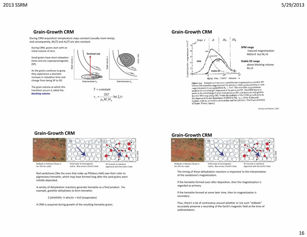
Grain‐Growth CRMDuring CRM acquisition temperature stays constant (usually room temp), and consequently, Ms[T] and HK[T] are also constant.
During CRM, grains start with an initial volume of zero.
Small grains have short relaxation times and are superparamagnetic (SP).
As the grains continue to grow, they experience a dramatic increase in relaxation time and change from being SP to SD.
Butle
r, 1992
nucleation
Terminal size
g g
The grain volume at which this transition occurs is called the blocking volume.
00
constant2v ln( )s
s K
TkT f t
M H
Grain‐Growth CRM
SPM rangeinduced magnetization
SPM
Stable SD
M(H)0 but Mr=0
Stable SD rangeabove blocking volumeMr0
Volume
Dunlop and Özdemir, 1997
2008
Grain‐Growth CRM
Red sandstones (like the ones that make up Pillsbury Hall) owe their color to pigmentary hematite, which may have formed long after the sand grains were initially deposited.
Tauxe,
Redbeds in Pakistan (Tauxe in her 20’s for scale)
Initial state of nonmagnetic matrix. Blue arrow is Earth’s field.
SP minerals in statistical alignment with the Earth’s field.
A variety of dehydration reactions generate hematite as a final product. For example, goethite dehydrates to form hematite:
2 (αFeOOH) → αFe2O3 + H2O (evaporates)
A CRM is acquired during growth of the resulting hematite grains.
2008
Grain‐Growth CRM
The timing of these dehydration reactions is important to the interpretation of the sandstone’s magnetization.
If the hematite formed soon after deposition, then the magnetization is d d i
Tauxe,
Redbeds in Pakistan (Tauxe in her 20’s for scale)
Initial state of nonmagnetic matrix. Blue arrow is Earth’s field.
SP minerals in statistical alignment with the Earth’s field.
regarded as primary.
If the hematite formed at some later time, then its magnetization is secondary.
Thus, there’s a lot of controversy around whether or not such “redbeds” accurately preserve a recording of the Earth’s magnetic field at the time of sedimentation.
2013 SSRM 5/29/2013
17
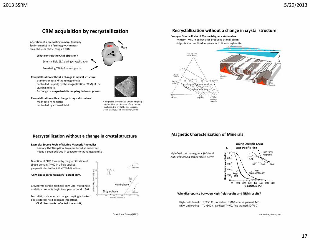
CRM acquisition by recrystallization
Alteration of a preexisting mineral (possibly ferrimagnetic) to a ferrimagnetic mineralTwo‐phase or phase‐coupled CRM
BearthCRM
Recrystallization without a change in crystal structure titanomagnetite titanomaghemite
TRMWhat controls the CRM direction?
External field (Be) during crystallization
Preexisting TRM of parent phase
controlled (in part) by the magnetization (TRM) of the starting mineral.Exchange or magnetostatic coupling between phases
Recrystallization with a change in crystal structure magnetite hematitecontrolled by external field
A magnetite crystal (∼ 30 μm) undergoing maghemitization. Because of the change in volume, the crystal begins to crack. [From Gapeyev and Tsel’movich, 1988.]
Recrystallization without a change in crystal structure Example: Source Rocks of Marine Magnetic Anomalies
Primary TM60 in pillow lavas produced at mid‐ocean ridges is soon oxidized in seawater to titanomaghemite
Jeff Gee
Recrystallization without a change in crystal structure
Example: Source Rocks of Marine Magnetic AnomaliesPrimary TM60 in pillow lavas produced at mid‐ocean ridges is soon oxidized in seawater to titanomaghemite
Direction of CRM formed by maghemitization of single‐domain TM60 in a field applied perpendicular to the initial TRM direction.
CRM forms parallel to initial TRM until multiphase
CRM direction ‘remembers’ parent TRM.
Multi‐phasep poxidation products begin to appear around z~0.6.
For z>0.6 , only when exchange coupling is broken does external field becomes important.
CRM direction is deflected towards B0
Özdemir and Dunlop (1985)
Single‐phase
High‐field thermomagnetic (Ms) and NRM unblocking Temperature curves
Young Oceanic CrustEast‐Pacific Rise
Magnetic Characterization of Minerals
High Tb/Tcmagnetite
NRM unblocking Temperature curves
Kent and Gee, Science, 1994
High‐Field Results: Tc~150 C, unoxidized TM60, coarse grained, MDNRM unblocking: TB >300 C, oxidized TM60, fine grained SD/PSD
Why discrepancy between High‐field results and NRM results?

2013 SSRM 5/29/2013
18
Authigenic formation of fine‐grained magnetite (SSD and SPM) is responsible for widespread chemical remagnetization of many carbonate rocks
CRMCRMcan heavily influenced by the magnetization of the parent mineral.
Sometimes it is parallel.Sometimes it is antiparallel (SELF‐REVERSAL) Sometimes it is oriented at an intermediate angle to both the parentSometimes it is oriented at an intermediate angle to both the parent mineral’s magnetization and the field at the time of alteration.
CRMs can be acquired sporadically through time, depending on the chemical environment of a rock.
It is difficult to ascribe an age to the minerals holding a CRM and consequently, paleomagnetists strive to remove CRM components from their samples during demagnetization
In general paleomagnetists like to steer clear of rocks that may have CRM components!
demagnetization.
Grains carrying CRM may have similar rock magnetic properties (Coercivity, relaxation time), which can be difficult to disentangle during demagnetization.
Extra Slides
Field Reversal vs. Self‐Reversal
Field Reversal : Geomagnetic Field behavior due to internal geodynamo
Self‐Reversal: Mineralogy or magnetic recording process unrelated to geomagnetic field
RM
Bearth
Minerals become magnetized antiparallel to an applied magneticfield

2013 SSRM 5/29/2013
19
David and Brunhes (France), 1904‐1906:
Clays baked in lavas, Massif Central, France
Early Results
– Same direction of TRM as lava– Changes in magnetization direction
=> polarity change
Matuyama (Japan), 1929:
– Quaternary lava = normal polarity– Pleistocene lava = opposite polarity
Courtillot a
nd Le Mou
e, 2007
Pleistocene lava = opposite polarity– Miocene = 3 different polarities– Link between polarity and age
Paleomagnetic results from lava flow at Pontfarein, with some representative diagrams: new results (circles) by Laj et al. [2002], and Brunhes’ and David’s original results (triangles)
Early Pleistocene age or olderEarly Results
Matuyama (1929)
100 Tertiary basalts coming from 38 sites in Japan
Many lavas were reversely magnetized
Polarity was correlated to stratigraphic position.magnetizations were arranged in two groups a Pleistocene one being
First study to show that the Earth’s field reversed polarity in the past
y g p pHe clearly identified the most recent field reversal (Brunhes‐Matuyama chron)
Stated that the polarity of the Earth’s magnetic field depended on time in an organized way.
groups, a Pleistocene one being normal and a pre‐Pleistocene one antipodal.
N‐type ferrimagnetism
Néel Classification of Ms‐T curves
Mechanisms for Self‐Revered Remanent Magnetization
Different combinations of AB, AA, BB interactions give rise different types of Ms‐T curves
N‐type: Ms=MA‐MB changes sign during heating
Ionic re‐ordering during extreme low‐temperature oxidation of titanomagnetites
Mechanisms for Self‐Revered Remanent Magnetization
y and Ba
nerje
e, 1966
temperature oxidation of titanomagnetites
Inversion of initial A‐site moment to a B‐site moment due to decomposition and ionic reordering
O’Reilly
Pavel V. Doubrovine and John A. Tarduno, On the l f ld f lf hcompositional field of self‐reversing titanomaghemite:
Constraints from Deep Sea Drilling Project Site 307, JGR, 110, 2005
Non‐reversible Self‐Reversal

2013 SSRM 5/29/2013
20
Mechanisms for Self‐Revered Remanent Magnetization
Magnetostatic or Exchange Coupling between two magnetic phases TcA >TcB
MB0>MA0V >>V
Phase B sees H0+ HA VB>>VAHA>H0 then MB is reversed
McElhinny and McFadden
/m
Mechanisms for Self‐Revered Remanent Magnetization
Negative Exchange Coupling
Variation of properties with Ti substitution in the titanohematite series.
kA/
Butler, 1992
Compositions around y=0.5 have the property of self‐reversed thermoremanent magnetization
Applied a field in the positive direction and cool through Curie temperature an negative remanence is produced!
Negative Exchange Coupling
Mechanisms for Self‐Revered Remanent Magnetization
Negative Exchange Coupling across a phase boundary
Dunlop and Özdemir, 1997
Self‐Reversing TRM Normal TRM
Fine‐scale microstructure, chemical disorder, and exchange coupling in ferrimagnetic titanohematites
1000 nm100 nm Lawson et al., 198
1
Transmission electron microscope image of antiphase domains and antiphase domain boundaries in the Ilm70Hem30
Transmission electron microscope image of large antiphase domains in the Ilm70Hem30 sample synthesized at 1300C and subsequently annealed at 900C

2013 SSRM 5/29/2013
21
Aeromagnetic anomalies caused by nanoscale lamellae structures in hemo‐ilmenite intergrowths
remanence‐dominated negative anomaliesAnomaly ~13 000 nT below back
lamellar magnetism
3 D image of Heskestad magnetic anomaly (southern Norway) from nearly 1 billion years old rocks.
ground
TEM image of the ilmenite host containing fine‐scale hematite precipitates. Scale bar = 100 nm.
McEnroe et al. (2002), McEnroe et al. 2004), Robinson et al., 2002
It is estimated that lamellar magnetism can result in saturation magnetization values of ~ 55 kA m‐1 (22 times larger than hematite and 11% of the moment in magnetite) and remanent magnetization up to 30 A/m.


![Volcanic activity sites along boundaries Where do volcanoes occur—and why? Divergent [MOR] boundaries – About 75% of erupted lava is found here – Basaltic.](https://static.fdocuments.us/doc/165x107/56649e9d5503460f94b9ddd9/volcanic-activity-sites-along-boundaries-where-do-volcanoes-occurand-why.jpg)