Magnetic Particle and Dye Penetrant Inspection - HSE
24
BEST PRACTICE FOR THE PROCUREMENT AND CONDUCT OF NON-DESTRUCTIVE TESTING Part 2: Magnetic Particle and Dye Penetrant Inspection
Transcript of Magnetic Particle and Dye Penetrant Inspection - HSE
BEST PRACTICE FOR THE PROCUREMENT ANDCONDUCT OF NON-DESTRUCTIVE TESTING
Part 2: Magnetic Particle and DyePenetrant Inspection
GAS AND CHEMICAL PROCESS SAFETYTECHNOLOGY DIVISION
April 2002

3
The recommendations contained in this document were aimed specifically to improve the inspection of conventional pressurised equipment. However, the drafting committee considers that these measures can also apply to any application of Magnetic Particle and Dye Penetrant Inspection including fairground or railway components, offshore equipment, and conventional plant in nuclear installations.
H Bainbridge Gas and Chemical Process Safety Technology Division Health and Safety Executive
1. INTRODUCTION Following the successful production of the Health and Safety Executive (HSE) document describing best practice for the procurement and application of manual ultrasonics [Ref. 1], the HSE have judged it appropriate to issue further best practice guidelines which identify when problems can arise in the selection and application of other NDT methods and what solutions might be adopted. The measures contained in this document are recommended by the HSE for the conduct of magnetic particle and dye penetrant inspection1. They are intended to promote the adoption of good practice and apply to in-service inspection of existing plant and to repairs. The guidelines could also be applicable to the inspections carried out during the manufacture of new or replacement plant. They apply both to inspections carried out by the NDT department of the company owning or manufacturing the plant and to those carried out by external NDT organisations under contract. In the latter case, they are intended to assist in the procurement process by highlighting the issues that need consideration. These measures are not intended to replace the relevant technical standards or to supersede them in any way. They identify the many factors which are important in the choice and application of the two methods, including technical ones. However, they do not provide any direction on the values to be adopted for the different technical parameters. This is the role of the detailed technical standards and the specific procedures derived from them. The guidelines also identify important issues beyond those covered in standards such as organisational matters and provide recommendations on these. The guidelines have been drawn up by a committee of experts assembled by the HSE for this purpose. Their names and affiliations are given in Appendix 1, from which it will be apparent that they represent a very wide range of those parts of British industry using the relevant NDT methods. In addition, they have considerable expertise in and responsibility for the application of NDT to industrial plant. The recommendations contained in these guidelines are based on two main sources. The first is a literature search and subsequent review of relevant published papers and articles regarding the reliability of the application of magnetic particle and dye penetrant inspection. The second basis for the recommendations is the collective experience and expertise of the committee mentioned earlier. Many of the members were also members of the PANI Management Committee and the committee responsible for the best practice document on manual ultrasonics. Both sources of information support the view that, if incorrectly chosen or incorrectly applied, both inspection methods can be ineffective. Defects may be overlooked or, alternatively, spurious indications may be mistaken for genuine defects, leading to unnecessary rejection of components or repairs. As a notable example, the NORDTEST trial results [Ref. 2] performed on 635 surface-breaking defects, in a total of 133 different specimens, inspected by 14 to 16 teams showed the following: ��57% detection rate for defects 2 mm deep rising to 93% for defects 8 mm deep when
applying MPI; ��44% detection rate for defects 10 mm long rising to 59% for defects 70 mm long when
applying MPI; ��70% detection rate for defects 2 mm deep rising to 92% for defects 5 mm deep when
applying dye penetrant; ��60% detection rate for defects 10 mm long rising to 65% for defects 50 mm long when
applying dye penetrant; 1 The term “inspection” is commonly used to mean both NDT and inspection in its wider sense. Throughout this document, it is used to mean NDT. The words inspector and operator are used interchangeably throughout the document to refer to those who apply and design NDT techniques.
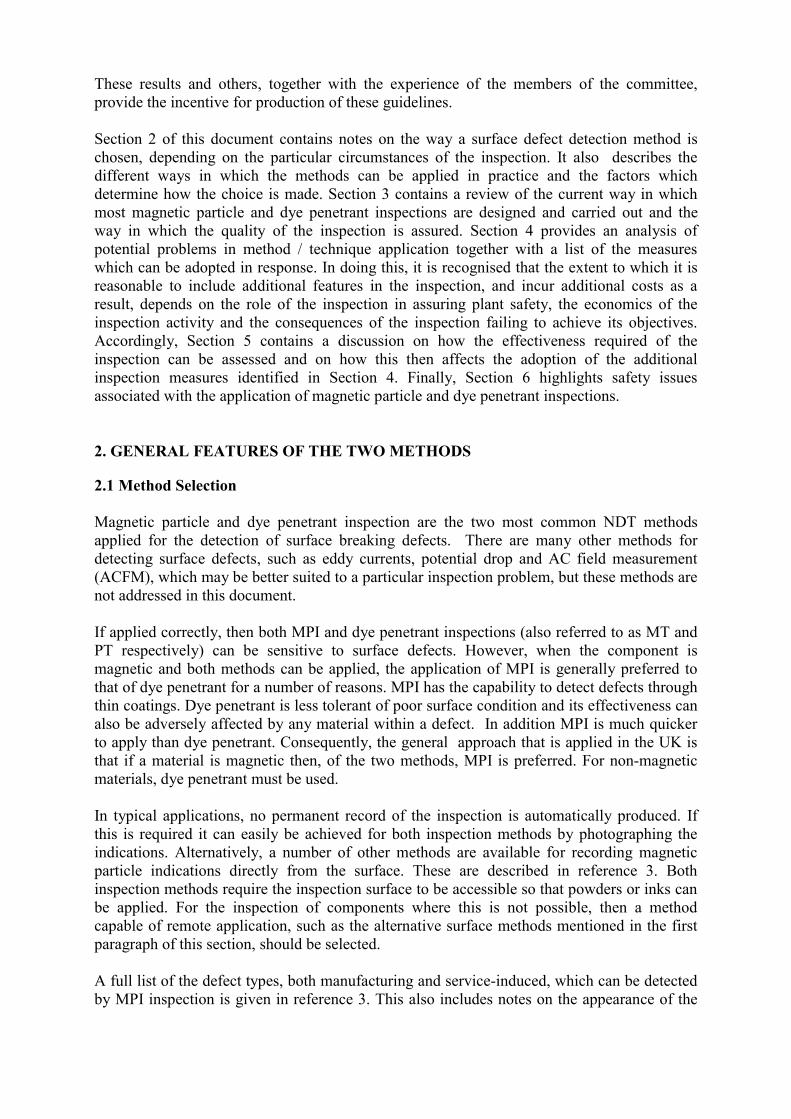
These results and others, together with the experience of the members of the committee, provide the incentive for production of these guidelines. Section 2 of this document contains notes on the way a surface defect detection method is chosen, depending on the particular circumstances of the inspection. It also describes the different ways in which the methods can be applied in practice and the factors which determine how the choice is made. Section 3 contains a review of the current way in which most magnetic particle and dye penetrant inspections are designed and carried out and the way in which the quality of the inspection is assured. Section 4 provides an analysis of potential problems in method / technique application together with a list of the measures which can be adopted in response. In doing this, it is recognised that the extent to which it is reasonable to include additional features in the inspection, and incur additional costs as a result, depends on the role of the inspection in assuring plant safety, the economics of the inspection activity and the consequences of the inspection failing to achieve its objectives. Accordingly, Section 5 contains a discussion on how the effectiveness required of the inspection can be assessed and on how this then affects the adoption of the additional inspection measures identified in Section 4. Finally, Section 6 highlights safety issues associated with the application of magnetic particle and dye penetrant inspections. 2. GENERAL FEATURES OF THE TWO METHODS
2.1 Method Selection Magnetic particle and dye penetrant inspection are the two most common NDT methods applied for the detection of surface breaking defects. There are many other methods for detecting surface defects, such as eddy currents, potential drop and AC field measurement (ACFM), which may be better suited to a particular inspection problem, but these methods are not addressed in this document. If applied correctly, then both MPI and dye penetrant inspections (also referred to as MT and PT respectively) can be sensitive to surface defects. However, when the component is magnetic and both methods can be applied, the application of MPI is generally preferred to that of dye penetrant for a number of reasons. MPI has the capability to detect defects through thin coatings. Dye penetrant is less tolerant of poor surface condition and its effectiveness can also be adversely affected by any material within a defect. In addition MPI is much quicker to apply than dye penetrant. Consequently, the general approach that is applied in the UK is that if a material is magnetic then, of the two methods, MPI is preferred. For non-magnetic materials, dye penetrant must be used. In typical applications, no permanent record of the inspection is automatically produced. If this is required it can easily be achieved for both inspection methods by photographing the indications. Alternatively, a number of other methods are available for recording magnetic particle indications directly from the surface. These are described in reference 3. Both inspection methods require the inspection surface to be accessible so that powders or inks can be applied. For the inspection of components where this is not possible, then a method capable of remote application, such as the alternative surface methods mentioned in the first paragraph of this section, should be selected. A full list of the defect types, both manufacturing and service-induced, which can be detected by MPI inspection is given in reference 3. This also includes notes on the appearance of the
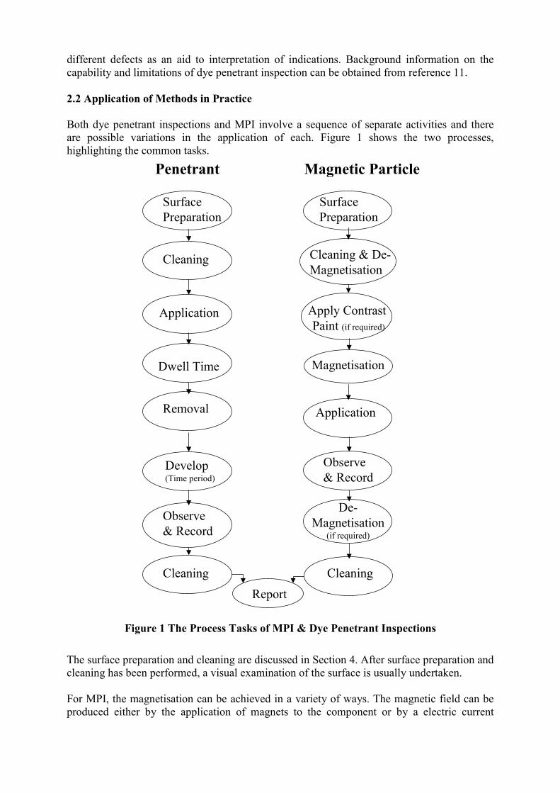
different defects as an aid to interpretation of indications. Background information on the capability and limitations of dye penetrant inspection can be obtained from reference 11. 2.2 Application of Methods in Practice Both dye penetrant inspections and MPI involve a sequence of separate activities and there are possible variations in the application of each. Figure 1 shows the two processes, highlighting the common tasks.
Surface Preparation
Surface Preparation
Cleaning Cleaning & De-Magnetisation
Magnetisation
Application
Application
Dwell Time
Removal
Develop(Time period)
Observe& Record
Observe & Record
Cleaning
Penetrant Magnetic Particle
Cleaning
Apply Contrast Paint (if required)
De-Magnetisation
(if required)
Report
Figure 1 The Process Tasks of MPI & Dye Penetrant Inspections The surface preparation and cleaning are discussed in Section 4. After surface preparation and cleaning has been performed, a visual examination of the surface is usually undertaken. For MPI, the magnetisation can be achieved in a variety of ways. The magnetic field can be produced either by the application of magnets to the component or by a electric current
flowing through or close to the component. Common practice in the UK for in-service inspection of welds is to use an AC yoke for MPI. The main techniques available for MPI are: Technique Description Magnets Permanent or electro- magnets are placed on the
component producing a magnetic field in the component between the poles.
Current flow with The current flowing through the component induces a electrical terminals or magnetic field. prods Threading cable An electric cable (or cables) is passed through the bore or
aperture of a component and the current flowing through the cable induces a magnetic field in the component.
Rigid Coil The component is placed within a current carrying coil and a magnetic field parallel to the axis of the coil is induced in the component.
Flexible cable A current carrying cable is wound around or laid across a component inducing a magnetic field in the component.
Electrical currents generating the magnetic fields can be DC, AC, full wave rectified or half wave rectified. Similarly, the magnets can be permanent, DC electro-magnets or AC electro-magnets. Guidance on the selection of the appropriate magnetisation technique can be found in the Published Document PD 6513: 1985 [Ref. 3] which supports the British Standard [Ref. 4]. Both inspection methods require the application of material to the surface of the component: for MPI this is a collection of magnetic particles which can be in the form of a dry powder or in liquid suspension. Contrast paint may be applied first to improve particle visibility. For dye penetrant the material used is a suitable liquid dye. Common UK practice for in-service inspection is to use red penetrant for dye penetrant inspection. The alternatives are:
Magnetic Particles Dry powder Solvent based suspension Water based suspension
Dye Penetrant Water washable penetrant Solvent removable penetrant Post Emulsifiable penetrant
Post emulsifiable penetrants use an emulsifier to aid removal after application either by oil or by a water wash. In all cases, compatibility between the materials used for the inspection and those under test must be assured. The use of dry magnetic powders has the disadvantage that once the particles are on the surface they lose their mobility. However, they are preferred for use on rough surfaces, where the liquid inks also have problems of mobility, and also on hot surfaces. The liquid magnetic inks usually have a higher sensitivity than powders due to the greater control which can be exercised over their application. The choice between solvent or water based magnetic inks needs to consider the surface wetting capability of the ink, the flammability and safety of the
solvent base and the potential corrosion effect of the water base. Reference 3 provides detailed advice on the choice and use of magnetic inks and powders. Similar considerations apply in the selection between solvent based dyes and water washable dyes with the additional factors of their penetrating ability and the need to clean the excess dye from the surface. Once the excess dye has been removed, developer is applied to draw the dye out of the defect and produce the indication. The developer needs to be compatible with the dye and the component. The developer needs to be left for a period of time sufficient to draw the dye out of the type of defects requiring detection. The final task before any cleaning and de-magnetisation (for MPI) which is necessary is the viewing of the indications. Lighting levels are important for this as discussed later and also have safety implications. The type of indication and the colour of the test surface will aid the selection of either colour contrast or fluorescent penetrants and magnetic powders . The use of fluorescent penetrants and fluorescent magnetic inks and powders viewed under ultraviolet light improves the visibility of fine cracks. 3. CURRENT PRACTICE FOR DESIGN AND CONTROL OF INSPECTIONS
Many magnetic particle and dye penetrant inspections are designed on the basis of a national or international standard such as BS 6072 [Ref. 4] for MPI and BS EN 571-1 [Ref. 5] for penetrant testing. The status of the various standards as of August 2001 is given in Appendix 2. The procedure for the inspection is frequently written to reflect simply the requirements of the standard in terms of the application of the equipment and the consumables. However, technique sheets are often provided to reflect plant and technique details. Operators are trained and qualified according to the requirements of a qualification scheme based on international standards such as BS EN 473 [Ref. 6] or ISO 9712 [Ref. 7]. These typically require operators to pass a written examination and to demonstrate their practical skill on test pieces containing defects. However, the test pieces on which an operator qualified may not be directly relevant to a particular inspection, geometry or defect. The authority to approve a procedure for a specific inspection based on the more general requirements of a code or standard requires skills and qualifications additional to those required of the operators who apply the inspection in the field. Such qualifications are denoted as Magnetic Testing (MT) Level 3 or Penetrant Testing (PT) Level 3 and involve demonstrating a greater understanding of the particular inspection method than expected of the Level 1 or 2 operators who normally carry out the inspection. The Level 3 inspector also has a good knowledge of other NDT methods. Complete definitions, for one particular qualification scheme (PCN), of the areas in which operators at Levels 1, 2 and 3 have demonstrated competence and the tasks they might perform are given in Appendix 3. The approach outlined above can be effective in certain circumstances and represents a cost effective way of defining and implementing requirements for both magnetic particle and dye penetrant inspection. However, there are circumstances in which it can lead to the adoption of unsatisfactory inspection procedures or to the use of operators whose training and qualifications are inappropriate to the particular inspection. It is crucial that such circumstances are recognised and appropriate additional requirements are specified. These are discussed below.
4. THE NEED FOR ADDITIONAL REQUIREMENTS
In this section, potential problems identified by both the review of previous studies and the committee of experts described in the Introduction, are discussed for both methods. In each case, the issues identified are followed by a number of recommendations to address the particular difficulty. It is not intended that all these be adopted in every case. Instead it will be necessary for those responsible for each inspection to determine which recommendations are appropriate. Advice on making a selection is included in Section 5 of these guidelines. 4.1 Defect Type Consideration of the defect parameters is important in selecting the appropriate method and technique to apply and then in ensuring that it is applied correctly. Dye penetrant inspection is particularly sensitive to round defects whilst MPI is well suited to cracks and linear discontinuities. The Nordtest NDT-programme (1984 - 1988) [Ref. 2] concluded that liquid penetrant testing with coloured chemicals gave the most reliable results when all types of surface breaking flaws have to be detected. This technique is particularly sensitive to round defects and gave a lower number of false calls than the other techniques. 4.1.1 Magnetic Particle Inspection Knowledge of the orientation of the cracks is required to ensure that the magnetic field is applied as near to perpendicular to the defects as possible. The results of a detailed study into the reliability of MPI [Ref. 8] recommended that the operators be given clear instructions concerning the types, orientations and sizes of the flaws being sought along with information on features of the component which may produce confusing indications. 4.1.2 Dye Penetrant Inspection Crack gape can determine the dwell time for the penetrant technique whilst the presence of oxide or other fillings within a defect will have a detrimental affect. These defect parameters are not usually known with any precision and so inspections are designed on the basis of experience for the particular defect type with regard to the appropriate dwell time etc. Recommendations �� Those requiring the inspection should provide a clear description of the defects which the
inspection must detect and size to those designing the inspection. Such a description should include as much information as possible on the possible ranges of the defect characteristics, particularly their anticipated shapes and orientations on the surface.
�� When no detailed defect description is available, the operator should be made aware of the type, orientations and size of indications which should be reported.
�� In addition to describing the defects to be detected, the particular defect characteristics which must be measured should also be specified by the inspection purchaser.
�� Inspection design should be based on defect descriptions. �� Inspection procedures should be designed or approved by an MT or PT Level 3 inspector
as appropriate. �� Operators should be required to report the coverage of the component which has been
achieved.
4.2 Component Geometry Component geometry can affect both magnetic particle and dye penetrant inspection. Sudden small changes in section such as weld toes and caps or threads in threaded components can lead to spurious indications. Both MPI and dye penetrant require the flow of penetrant or particles over the surface and it is necessary to ensure an even distribution over the inspection zone for the required time to allow indications to be produced. The geometry and orientation of the component may interfere with this distribution. As noted in Section 3 above, operators gain their qualifications using test pieces which may be quite different from the component under test. If the geometry of the component is novel and there are associated problems which the operators have not encountered previously, the Level 3 inspector may decide that there is merit in producing realistic practice specimens. These would enable the operators to improve their skills and confidence prior to carrying out the inspection in earnest. 4.2.1 Magnetic Particle Inspection The magnetic flux density induced in the component depends on the geometry of the component and its magnetic properties and it is important to ensure that the correct flux density is attained in the regions where defects are expected to occur. British Standards require a minimum magnetic flux density of 0.72T to be attained in the region of the defects being sought [Refs. 3 and 4]. T is SI unit, Tesla, for magnetic flux density and B is the symbol used in equations to denote magnetic flux density. The flux density is a difficult quantity to measure and its value has to be calculated from indirect measurements. PD 6513: 1985 [Ref. 3] gives a good basic description of the flux density and the steps required to achieve the recommended value. [Note: the new European Standards define the tangential field strength in kA/m rather than the magnetic flux density]. A study carried out by TWI [Ref. 8] shows that a flux density of 1.1T is optimal for detecting flaws without generating an excessive number of false calls. The problem is that, for all methods of magnetisation, flux density varies over the surface of the component, usually being greatest near the magnetic poles if magnets are used or near the prods or inducing cable if current flow is used. If a flux density of the required value is established away from the poles or prods, the value near them may be too high, thereby degrading the inspection. Conversely, achievement of the desired value of flux density at the places where it is at a maximum may mean that it is too low if the test is applied too far away from the poles or prods. Careful design is needed to avoid these problems, taking account of both component geometry and magnetic properties. This is why procedures should be designed by an MT Level 3 inspector who will have demonstrated his ability to develop satisfactory procedures for a particular component within the general requirements of a standard. There are a number of techniques for indicating field direction and for field strength measurement [Ref. 4]. When applying these techniques, care is required to define the relationship between the parameter being measured and the consequence for the inspection. The measurement and the position of the measurement should be recorded. 4.2.2 Dye Penetrant Inspection The geometry and orientation of the component may mean that the penetrant may collect in certain areas and flow away from others. Similar problems with geometry can be encountered when trying to remove excess penetrant from the component. Particular geometries may determine the technique to be applied e.g. water washable penetrant is generally used on
threaded components. The procedure should address these issues to ensure a reliable inspection. Recommendations �� The specific geometry and magnetic properties (for MPI) of the component should be
considered when designing the inspection procedure. �� A qualified MT/PT Level 3 inspector should either be used to design or approve the
inspection procedure as appropriate. �� If judged necessary by the Level 3 inspector because of the novelty of the inspection, the
operators who carry out the inspection should be given specific training and practice with feedback on representative test pieces containing defects.
4.3 Component Material As noted in Section 2, magnetic materials tend to be inspected by MPI whilst dye penetrant is applied to non-magnetic materials, including non-metallics. However, there are certain magnetic materials such as Monel which are particularly difficult to inspect with MPI and these are usually inspected using dye penetrants. 4.3.1 Magnetic Particle Inspection The component needs to be thoroughly de-magnetised prior to MPI. If the component retains some residual magnetism, as can be imparted during welding, the sensitivity of the test may be reduced or false indications produced. The magnetic properties of the component may need to be known in order to be able to calculate the necessary parameters such as prod or pole spacing or current flow. Variations in permeability between the weld and the parent plate can lead to false calls. 4.3.2 Dye Penetrant Inspection Dye penetrant inspection is less dependent on the component material but oxide layers or other contamination on the surface will affect the performance. In addition the material compatibility of the penetrant and cleaning fluids needs to be assessed. Recommendations �� Inspection procedures for non-standard materials should be designed or approved by
MT/PT Level 3 inspectors as appropriate with specific knowledge of such inspections. The procedure should be developed using representative test pieces in the same material as the component if the Level 3 judges that this is necessary.
�� In the case of MPI, for non-standard materials, inspectors should be given specific training and the opportunity to practice in advance of an inspection on representative test pieces containing defects.
�� Personnel qualification arrangements (in-house or external) for the inspection of non-standard materials should be established in the absence of suitable national certification arrangements.
4.4 Surface Condition & Coatings Surface roughness has an adverse affect on both methods by restricting particle flow over the surface and generating false indications. For MPI it can reduce contact between prods or poles and the component, whilst for dye penetrant it can make cleaning difficult. The level of surface finish should be commensurate with the minimum size of defect that is required to be detected and the effectiveness level of the inspection (see Section 5). Bowker & Chapman
[Ref. 10] give capabilities for reliable detection for MPI for various surface finishes. As described in Section 4.2, step changes in the surface profile such as at weld toes can lead to spurious indications which can also mask genuine defect indications. Even if little preparation is deemed to be required, such step changes may need to be blended out and other surface irregularities such as weld spatter removed prior to the inspection. 4.4.1 Magnetic Particle Inspection MPI has some capability to detect defects hidden beneath coatings. A layer of contrast paint is often applied over a component to improve the visibility of indications. The guidance document for BS6072 [Ref. 3] states that any thickness of contrast paint above 50�m reduces the sensitivity of the test and so the paint needs to be applied carefully and evenly. Similarly any existing coating or paint layer on the component will have an adverse affect on defect detection if it is greater than 50 �m thick. If an inspection must be performed through a coating greater than 50 �m then an alternative method such as eddy currents should be considered. 4.4.2 Dye Penetrant Inspection Dye penetrant only detects defects which break the surface and the surface finish requirements are higher than those for MPI. Some mechanical cleaning techniques, particularly shot blasting, could lead to the crack openings being closed up and hence reduce the sensitivity of the inspection. Such cleaning techniques should therefore be avoided if possible. If they are used, acid etching should be considered to re-open any defects, provided this is compatible with the component material. Recommendations �� Paint and coatings should be removed prior to inspection unless they can be shown not to
be detrimental to the inspection. �� If coating removal is not carried out, MPI inspection procedures for coated or painted
surfaces should include a check of the coating thickness and check that the coating is securely bonded to the surface. Paint should always be removed from points where electrical contact is to be made.
�� If paint layers exceeding 50 �m in thickness are not removed, alternative methods such as eddy current testing should be used.
�� The procedure should define a level of surface finish which is commensurate with the minimum size of defect that is required to be detected.
�� The operator should be satisfied that, as a minimum, the surface finish of the component meets the requirements of the appropriate inspection procedure and is satisfactory for inspection.
�� Mechanical cleaning should be applied with care prior to dye penetrant inspection to avoid closing any defects. The use of acid etching should be considered if it is judged necessary to re-open any defects.
4.5 Cleaning Cleaning is crucial to the success of both dye penetrant and magnetic particle inspections. For both methods, the inspection procedure should specify the cleaning requirements for the particular inspection and the operator should check that what has been achieved is satisfactory. A note should be made in the inspection report of any problems.
If the presence of any residual testing materials will have an adverse affect on the component material or any subsequent surface treatment then the inspected surfaces should be cleaned after application of either technique. This should be specified in the procedure. 4.5.1 Magnetic Particle Inspection The mobility of MPI particles is greatly influenced by the presence of foreign matter such as dirt, rust, scale, grease, oil or water. Certain types of corrosion products will produce spurious indications at their boundaries. If dry powder is used then the surface needs to be dried thoroughly after cleaning. 4.5.2 Dye Penetrant Inspection For dye penetrants, any dirt which obstructs the defect opening or grease or solvent on the surface which affects the dye will have an adverse affect on the detection capability of the technique. Recommendations �� The presence and nature of any surface contaminants should be checked and a suitable
solvent or detergent used to remove them. �� All procedures should specify the cleaning method to be used. �� The operator should satisfy himself (or herself) that the surface is sufficiently clean to
allow proper application of the technique, making a note in the inspection report of any problems.
�� The procedure should specify any post inspection cleaning requirements. 4.6 Access Direct physical access to surfaces under test is necessary for the normal application of both magnetic particle and dye penetrant inspections. Where remote inspection is necessary, other inspection methods should be used. Good access is needed to allow techniques to be applied in the way in which they are specified and for satisfactory viewing of any indications found. Adequate lighting levels as specified in the inspection standard need to be applied and these are most easily achieved if access is good. Lighting levels should be measured to ensure compliance with the standard. Unstable platforms will not prevent application of surface defect detection methods but, along with difficult access conditions generally, will affect the ability of the operator to concentrate fully. Rope access to surfaces requires specific training and assessment to ensure that operators are capable of applying inspections effectively under such conditions. There are also safety implications associated with access - see Section 6. Recommendations �� Operators should be provided with a stable platform from which to conduct the inspection
with good access to the inspection surface. The lighting levels specified in the relevant standard should be applied and measured.
�� All impediments to access should be removed wherever practicable. �� Consideration should be given to the remote application of inspection methods such as
eddy currents whenever access to the inspection surface is intrinsically difficult. �� Operators should report any factors which have prevented the inspection from being
carried out as intended.
4.7 Operator Performance A number of exercises to investigate the effectiveness of surface defect detection techniques have been carried out as discussed in the introduction to these guidelines. These all show the importance of operator qualifications in determining the outcome of the test. The difference in performance between certificated and non-certificated operators is most marked for smaller flaws. In the Nordtest exercise [Ref. 2], for example, the overall detection rate for 1mm deep defects using both methods by qualified operators was 40% higher than that for those who were not appropriately qualified. Both dye penetrant and magnetic particle testing require an understanding of the physical principles involved if they are to be applied effectively. They also require clear instructions on how the inspection should be applied. The latter are provided by the procedure as discussed above and also by supplementary instruction from the Level 3 inspector controlling the inspection. Finally, interpretation of defect indications is assisted by providing the inspectors with clear instructions on the types and sizes of the defects which are being sought as highlighted in Section 4.1.1. The operator should also be aware of any possible sources of confusing indications associated with features of the component being inspected. The ability of the operator to produce good results is enhanced if the recommendations on access and working conditions (see Section 4.6) are met. Unreasonable time pressure and excessively long times on duty will cause a deterioration of inspection quality. A maximum length of time carrying out continuous inspection of 2 hours has been suggested [Ref. 9]. Incentives to complete the maximum amount of inspection in a given time could lead to a deterioration in inspection quality. The eyesight of operators is of prime importance and should be checked regularly, as required by the appropriate standard [Refs. 6, 7] If the highest reliability possible is sought, the whole or part of the inspection or the interpretation of the indications can be repeated independently to reduce human errors. Recommendations �� Operators should be given appropriate training and qualification. �� Operators should be given practice on realistic test pieces prior to the inspection if judged
beneficial by the Level 3 inspector. �� Inspections should be subject to supervision and audit, particularly when they are carried
out on a large scale. �� Good access and lighting conditions should be provided. �� A reasonable time should be allocated for the inspection and should include regular breaks
for the operators with a limit on the maximum length of time spent continuously testing. �� The eyesight of operators should be checked as required by the appropriate standard. �� The environment in which the inspection is carried out should be as benign as possible
with regard to ambient temperature, dust, shelter from the elements, requirements for restrictive protective clothing and so on.
�� Independent repetition of all or part of the inspection should be considered when the level of reliability sought is very high.
4.8 Organisation and Procurement of NDT It is crucial, if NDT is to be effective, that the requirements are defined as discussed in 4.1 above. The inspection method must be chosen and the procedure must then be written taking these requirements into account along with the other geometry and material requirements discussed above. Level 3 inspectors have a role in ensuring that this activity is carried out
correctly. It is important that the contractual arrangements define the relative responsibilities of purchaser and supplier. As described in the previous section incentives to complete the maximum amount of inspection in a given time could lead to a deterioration in inspection quality. Care needs to be taken when agreeing contracts to ensure that the NDT vendor is not encouraged to risk safety and quality for speed. It is also important that organisations contracted to undertake the NDT exercise adequate control over how it is implemented. NDT companies should have a certified quality control system in place relating to the whole of their activities against which they have been audited. These should include aspects such as purchase and control of consumables as well as the way the company is organised and the way in which the inspections themselves are controlled. The quality system should specify the role of the Level 3 inspector. The recommendations of the present document should be considered in producing and assessing the quality system. Accreditation schemes for NDT companies are available and can provide reassurance to the purchaser of NDT services that the supplier’s quality system is an appropriate one.. Recommendations �� The contractual responsibilities of purchaser and supplier should be made clear when
inspection contracts are placed. �� NDT companies should have a certified quality system for controlling the implementation
of the NDT. It should be recognised that operators must work within the context of a company which can support their activities and not as individuals. Consequently when employed directly by the purchaser, operators should work within the purchaser’s quality system.
�� Purchasers of NDT services should consider requiring their suppliers to be suitably accredited or audit the NDT vendor themselves.
5. INSPECTION IMPROVEMENTS AND COMPONENT RISK
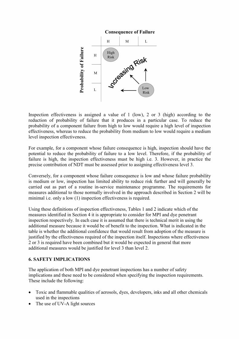
The previous section describes the different measures which can be taken to ensure that magnetic particle and dye penetrant inspections are as effective as possible. It is necessary for those who commission or purchase inspections to determine which of the measures is appropriate to their particular inspection and whether to adopt it. A major factor in determining which additional measures should be used is the role of the inspection and the effectiveness required from it in reducing the risk of component failure. The risk of component failure is determined by a combination of both the consequence and the probability of failure. The consequence relates to the safety or economic effects of the failure. Inspection can only reduce risk by reducing the probability of failure, which , for example, could be related to the likelihood of defects being present in the component that could lead to failure. If the consequence and probability parameters are denoted as high (H), medium (M) or low (L), their combined effects can be indicated on a 3x3 matrix as follows:
Consequence of Failure
Prob
abili
ty o
f Fai
lure
H M L
H
M
L
HighRisk
Low Risk
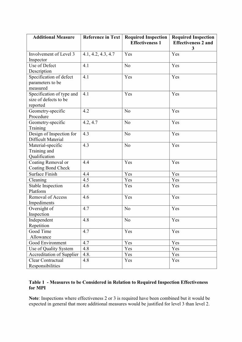
Inspection effectiveness is assigned a value of 1 (low), 2 or 3 (high) according to the reduction of probability of failure that it produces in a particular case. To reduce the probability of a component failure from high to low would require a high level of inspection effectiveness, whereas to reduce the probability from medium to low would require a medium level inspection effectiveness. For example, for a component whose failure consequence is high, inspection should have the potential to reduce the probability of failure to a low level. Therefore, if the probability of failure is high, the inspection effectiveness must be high i.e. 3. However, in practice the precise contribution of NDT must be assessed prior to assigning effectiveness level 3. Conversely, for a component whose failure consequence is low and whose failure probability is medium or low, inspection has limited ability to reduce risk further and will generally be carried out as part of a routine in-service maintenance programme. The requirements for measures additional to those normally involved in the approach described in Section 2 will be minimal i.e. only a low (1) inspection effectiveness is required. Using these definitions of inspection effectiveness, Tables 1 and 2 indicate which of the measures identified in Section 4 it is appropriate to consider for MPI and dye penetrant inspection respectively. In each case it is assumed that there is technical merit in using the additional measure because it would be of benefit to the inspection. What is indicated in the table is whether the additional confidence that would result from adoption of the measure is justified by the effectiveness required of the inspection itself. Inspections where effectiveness 2 or 3 is required have been combined but it would be expected in general that more additional measures would be justified for level 3 than level 2. 6. SAFETY IMPLICATIONS
The application of both MPI and dye penetrant inspections has a number of safety implications and these need to be considered when specifying the inspection requirements. These include the following: �� Toxic and flammable qualities of aerosols, dyes, developers, inks and all other chemicals
used in the inspections �� The use of UV-A light sources
�� The use of low light levels to facilitate the use of UV lamps may cause safety problems i.e. slips, trips and falls.
�� Access �� Working in confined spaces �� The toxicity of cleaning fluids and their use in confined spaces �� The electrical safety of inspection equipment �� Cleaning of live plant �� Working at heights �� Intrinsically safe equipment �� Working on live plant and permits to work. All safety precautions recommended by the manufacturers of all chemicals used should be observed. The duty for ensuring that this is done lies with the company or organisation employing the staff who are in contact with the various chemicals. A similar duty relates to the use of UV-A lamps. The site owner has a duty to ensure that the employer of all inspection staff, if different, has a suitable system in place for safe application of all inspections. REFERENCES
1. “Best Practice for the Procurement and Conduct of Non-Destructive Testing. Part 1: Manual Ultrasonic Inspection”, HSE Gas and Process Safety Technology Division, November 2000
2. "Reliability of Liquid Penetrant and Magnetic Particle Inspection", P. Kauppinen and J Sillanpaa, Proceedings of the 10th International Conference on NDE in the Nuclear and Pressure Vessel Industries, 1990, Ed M J Whittle, J E Doherty and K Iida, ASM International.
3. “Magnetic particle flaw detection. A guide to the principles and practice of applying
magnetic particle flaw detection in accordance with BS6072.”, British Standard PD 6513: 1985
4. “Method for Magnetic particle flaw detection”, British Standard BS 6072 : 1981
[Note that this standard is still current because not all of the BS EN standards which will replace it have been issued - see Appendix 2]
5. “Non-destructive testing – Penetrant testing, Part1. General principles” British
Standard BS EN 571-1 : 1997 6. “Non-destructive testing. Qualification and certification of NDT personnel. General
principles”, British Standard BS EN 473 : 2000 7. “Non-destructive Testing – Qualification and Certification of Personnel” International
Standards Organisation ISO 9712, 1999 8. "Optimisation of Magnetic Particle Inspection", M. E. Forshaw and P. J. Mudge,
Proceedings of the 4th European Conference on NDT, London, Sept. 1987, Vol. 4 pp 2729-2740. Edited by J.M. Farley.

9. “A practical approach to probability of detection with magnetic particle inspection”, D J Lovejoy, Insight 37 12, Dec 1995
10. "The Production of Capability Statements for Standard NDT Procedures", R. K.
Chapman and K. J. Bowker, INSIGHT 43 1 pp 36-38, January 2001. 11. "The Capabilities and Limitations of NDT - Part 2. Penetrant Methods", Dr D
Lovejoy 1989, ISBN 0 903 132 125.
Additional Measure Reference in Text Required Inspection Effectiveness 1
Required Inspection Effectiveness 2 and
3 Involvement of Level 3 4.1, 4.2, 4.3, 4.7 Yes Yes Inspector Use of Defect 4.1 No Yes Description Specification of defect parameters to be measured
4.1 Yes Yes
Specification of type and size of defects to be
4.1 Yes Yes
reported Geometry-specific Procedure
4.2 No Yes
Geometry-specific Training
4.2, 4.7 No Yes
Design of Inspection for Difficult Material
4.3 No Yes
Material-specific Training and Qualification
4.3 No Yes
Coating Removal or Coating Bond Check
4.4 Yes Yes
Surface Finish 4.4 Yes Yes Cleaning 4.5 Yes Yes Stable Inspection Platform
4.6 Yes Yes
Removal of Access 4.6 Yes Yes Impediments Oversight of Inspection
4.7 No Yes
Independent Repetition
4.8 No Yes
Good Time 4.7 Yes Yes Allowance Good Environment 4.7 Yes Yes Use of Quality System 4.8 Yes Yes Accreditation of Supplier 4.8. Yes Yes Clear Contractual 4.8 Yes Yes Responsibilities
Table 1 - Measures to be Considered in Relation to Required Inspection Effectiveness for MPI
Note: Inspections where effectiveness 2 or 3 is required have been combined but it would be expected in general that more additional measures would be justified for level 3 than level 2.
Additional Measure Reference in Text Required Inspection
Effectiveness 1 Required Inspection Effectiveness 2 and
3 Involvement of Level 3 4.1, 4.2, 4.3, 4.7 Yes Yes Inspector Use of Defect 4.1 No Yes Description Specification of defect parameters to be measured
4.1 Yes Yes
Specification of type and size of defects to be
4.1 Yes Yes
reported Geometry-specific Procedure
4.2 No Yes
Geometry-specific Training
4.2, 4.7 No Yes
Coating Removal 4.4 Yes Yes
Surface Finish 4.4 Yes Yes Cleaning 4.5 Yes Yes Stable Inspection Platform
4.6 Yes Yes
Removal of Access 4.6 Yes Yes Impediments Oversight of Inspection
4.7 No Yes
Independent Repetition
4.8 No Yes
Good Time 4.7 Yes Yes Allowance Good Environment 4.7 Yes Yes Use of Quality System 4.8 Yes Yes Accreditation of Supplier 4.8. Yes Yes Clear Contractual 4.8 Yes Yes Responsibilities
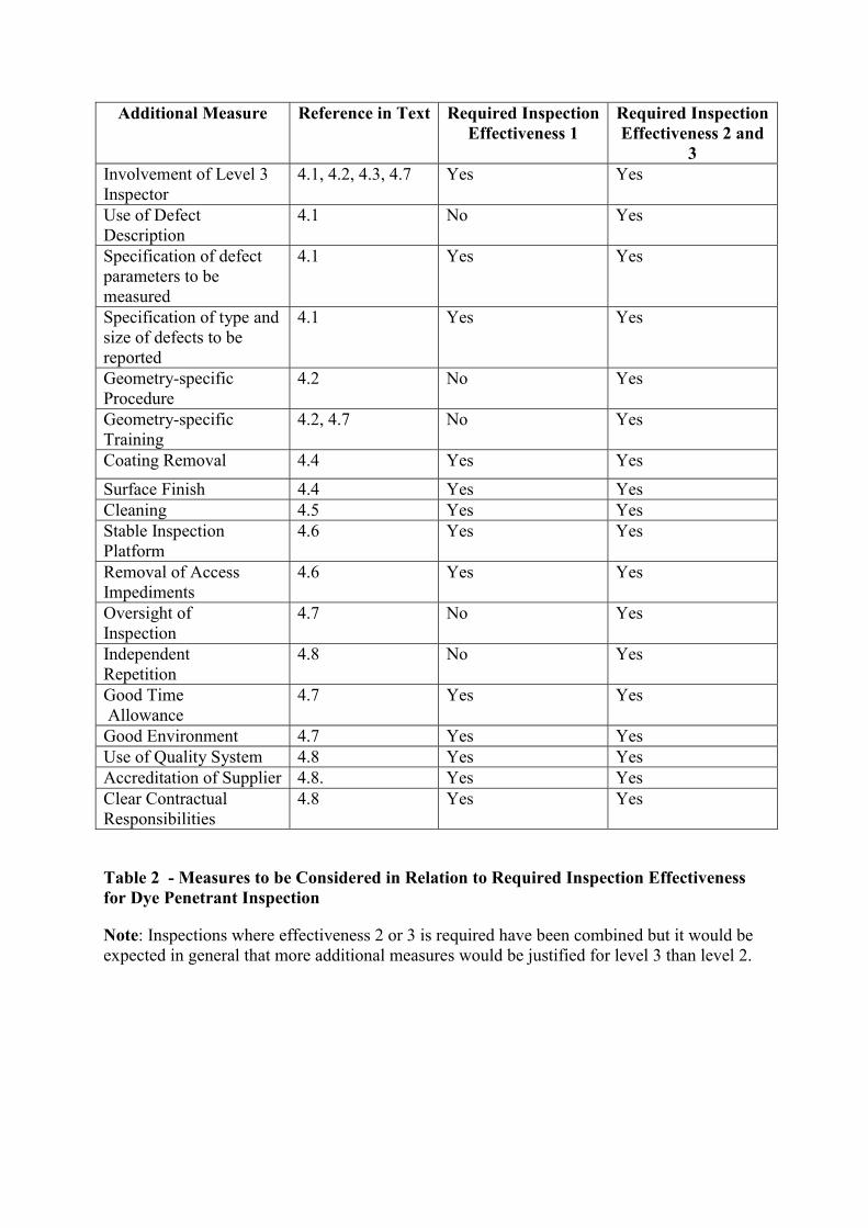
Table 2 - Measures to be Considered in Relation to Required Inspection Effectiveness for Dye Penetrant Inspection
Note: Inspections where effectiveness 2 or 3 is required have been combined but it would be expected in general that more additional measures would be justified for level 3 than level 2.
(pr) EN Number Progress Status
Title of Standard Equivalent British Standard
Publication Date
BS EN 1290
Current
Non destructive examination of welds: Magnetic particle examination of welds : Method
BS6072
06-1998
BS EN 1291 Current
Non destructive examination of welds: Magnetic particle testing of welds: Acceptance Levels
N/A
06-1998
00/710451 DC Identical to prEN ISO 12707:2000
Current, Draft for Public Comment
NDT Terminology - part 7 : Terms used in magnetic particle testing
BS 3683 Pt.2
06-2000
96/702019 DC
Current, Draft for Public
Non-Destructive Testing-
BS 6072
02-1996
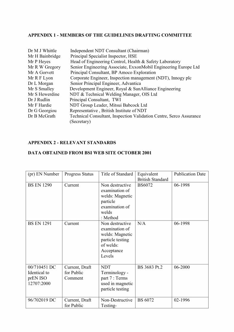
APPENDIX 1 - MEMBERS OF THE GUIDELINES DRAFTING COMMITTEE
Dr M J Whittle Independent NDT Consultant (Chairman) Mr H Bainbridge Principal Specialist Inspector, HSE Mr P Heyes Head of Engineering Control, Health & Safety Laboratory Mr R W Gregory Senior Engineering Associate, ExxonMobil Engineering Europe Ltd Mr A Gorvett Principal Consultant, BP Amoco Exploration Mr R F Lyon Corporate Engineer, Inspection management (NDT), Innogy plc Dr L Morgan Senior Principal Engineer, Advantica Mr S Smalley Development Engineer, Royal & SunAlliance Engineering Mr S Hewerdine NDT & Technical Welding Manager, OIS Ltd Dr J Rudlin Principal Consultant, TWI Mr F Hardie NDT Group Leader, Mitsui Babcock Ltd Dr G Georgiou Representative , British Institute of NDT Dr B McGrath Technical Consultant, Inspection Validation Centre, Serco Assurance
(Secretary)
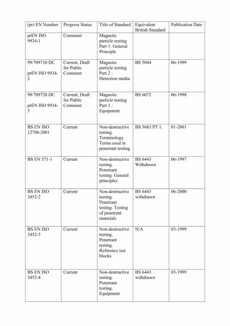
APPENDIX 2 - RELEVANT STANDARDS
DATA OBTAINED FROM BSI WEB SITE OCTOBER 2001
(pr) EN Number Progress Status
Title of Standard Equivalent British Standard
Publication Date
prEN ISO 9934-1
Comment
Magnetic particle testing Part 1: General Principle
99/709710 DC prEN ISO 9934-2
Current, Draft for Public Comment
Magnetic particle testing Part 2 : Detection media
BS 5044
06-1999
98/709728 DC prEN ISO 9934-3
Current, Draft for Public Comment
Magnetic particle testing Part 3 : Equipment
BS 6072
06-1998
BS EN ISO 12706:2001
Current
Non-destructive testing. Terminology. Terms used in penetrant testing
BS 3683 PT 1.
01-2001
BS EN 571-1
Current
Non-destructive testing. Penetrant testing. General principles
BS 6443 Withdrawn
06-1997
BS EN 3452-2
ISO Current
Non-destructive testing. Penetrant testing. Testing of penetrant materials
BS 6443 withdrawn
06-2000
BS EN 3452-3
ISO Current
Non-destructive testing. Penetrant testing. Reference test blocks
N/A
03-1999
BS EN 3452-4
ISO Current
Non-destructive testing. Penetrant testing. Equipment
BS 6443 withdrawn
03-1999
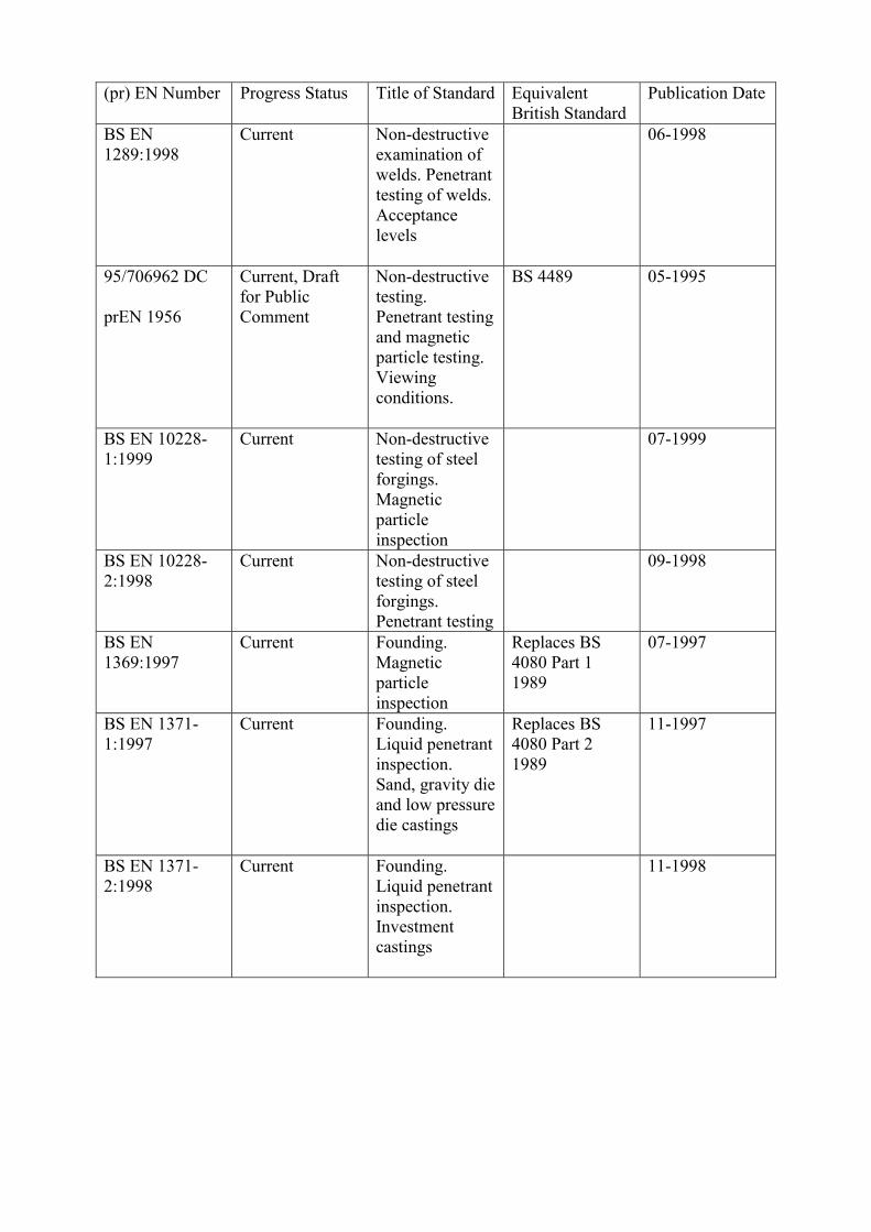
(pr) EN Number Progress Status
Title of Standard Equivalent British Standard
Publication Date
BS EN 1289:1998
Current Non-destructive examination of welds. Penetrant testing of welds. Acceptance levels
06-1998
95/706962 DC prEN 1956
Current, Draft for Public Comment
Non-destructive testing. Penetrant testing and magnetic particle testing. Viewing conditions.
BS 4489
05-1995
BS EN 10228-1:1999
Current
Non-destructive testing of steel forgings. Magnetic particle inspection
07-1999
BS EN 10228- Current Non-destructive 09-19982:1998 testing of steel
forgings. Penetrant testing
BS EN 1369:1997
Current Founding. Magnetic particle inspection
Replaces BS 4080 Part 1 1989
07-1997
BS EN 1371- Current Founding. Replaces BS 11-1997 1:1997 Liquid penetrant
inspection. Sand, gravity die and low pressure die castings
4080 Part 2 1989
BS EN 1371-2:1998
Current
Founding. Liquid penetrant inspection. Investment castings
11-1998
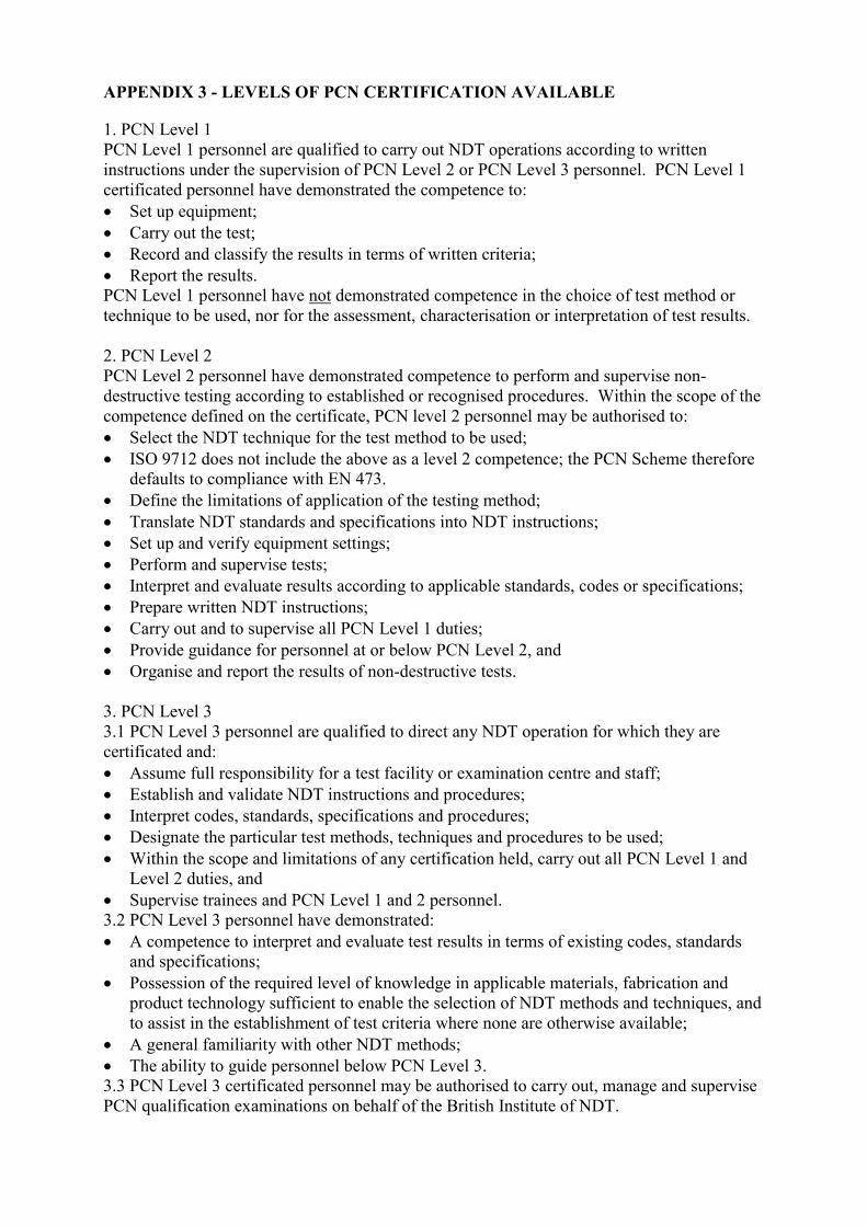
APPENDIX 3 - LEVELS OF PCN CERTIFICATION AVAILABLE
1. PCN Level 1 PCN Level 1 personnel are qualified to carry out NDT operations according to written instructions under the supervision of PCN Level 2 or PCN Level 3 personnel. PCN Level 1 certificated personnel have demonstrated the competence to: �� Set up equipment; �� Carry out the test; �� Record and classify the results in terms of written criteria; �� Report the results. PCN Level 1 personnel have not demonstrated competence in the choice of test method or technique to be used, nor for the assessment, characterisation or interpretation of test results. 2. PCN Level 2 PCN Level 2 personnel have demonstrated competence to perform and supervise non-destructive testing according to established or recognised procedures. Within the scope of the competence defined on the certificate, PCN level 2 personnel may be authorised to: �� Select the NDT technique for the test method to be used; �� ISO 9712 does not include the above as a level 2 competence; the PCN Scheme therefore
defaults to compliance with EN 473. �� Define the limitations of application of the testing method; �� Translate NDT standards and specifications into NDT instructions; �� Set up and verify equipment settings; �� Perform and supervise tests; �� Interpret and evaluate results according to applicable standards, codes or specifications; �� Prepare written NDT instructions; �� Carry out and to supervise all PCN Level 1 duties; �� Provide guidance for personnel at or below PCN Level 2, and �� Organise and report the results of non-destructive tests. 3. PCN Level 3 3.1 PCN Level 3 personnel are qualified to direct any NDT operation for which they are certificated and: �� Assume full responsibility for a test facility or examination centre and staff; �� Establish and validate NDT instructions and procedures; �� Interpret codes, standards, specifications and procedures; �� Designate the particular test methods, techniques and procedures to be used; �� Within the scope and limitations of any certification held, carry out all PCN Level 1 and
Level 2 duties, and �� Supervise trainees and PCN Level 1 and 2 personnel. 3.2 PCN Level 3 personnel have demonstrated: �� A competence to interpret and evaluate test results in terms of existing codes, standards
and specifications; �� Possession of the required level of knowledge in applicable materials, fabrication and
product technology sufficient to enable the selection of NDT methods and techniques, and to assist in the establishment of test criteria where none are otherwise available;
�� A general familiarity with other NDT methods; �� The ability to guide personnel below PCN Level 3. 3.3 PCN Level 3 certificated personnel may be authorised to carry out, manage and supervise PCN qualification examinations on behalf of the British Institute of NDT.
Where PCN Level 3 duties regularly require the individual to apply routine NDT by a method or methods, the British Institute of NDT strongly recommends that this person should hold and maintain PCN Level 2 certification in those methods. This report contains notes on good practice which are not compulsory but which you may find helpful in considering what you need to do. EIMSRG/152