MAGNETIC ELLIPTICAL TRAINER › images › I › A1ITRU0... · 2016-10-07 · MAGNETIC ELLIPTICAL...
15
MAGNETIC ELLIPTICAL TRAINER SF-E906 USER MANUAL IMPORTANT! Read all instructions carefully before using this product. Retain owner’s manual for future reference. For customer service, please contact: [email protected]
Transcript of MAGNETIC ELLIPTICAL TRAINER › images › I › A1ITRU0... · 2016-10-07 · MAGNETIC ELLIPTICAL...

MAGNETIC ELLIPTICAL TRAINER
SF-E906
USER MANUAL
IMPORTANT! Read all instructions carefully before using this product. Retain owner’s
manual for future reference. For customer service, please contact:

IMPORTANT SAFETY INFORMATION
We thank you for choosing our product. To ensure your safety and health, please use this
equipment correctly. It is important to read this entire manual before assembling and using the
equipment. Safe and effective use can only be assured if the equipment is assembled,
maintained, and used properly. It is your responsibility to ensure that all users of the equipment
are informed of all warnings and precautions.
1. Before starting any exercise program you should consult your physician to determine if
you have any medical or physical conditions that could put your health and safety at risk or
prevent you from using the equipment properly. Your physician’s advice is essential if you
are taking any medication that may affect your heart rate, blood pressure, or cholesterol
level.
2. Be aware of your body’s signals. Incorrect or excessive exercise can damage your health.
Stop exercising if you experience any of the following symptoms: pain, tightness in your
chest, irregular heartbeat, shortness of breath, lightheadedness, dizziness, or feelings of
nausea. If you do experience any of these conditions, you should consult your physician
before continuing with your exercise program.
3. Keep children and pets away from the equipment. The equipment is designed for adult
use only.
4. Use the equipment on a solid, flat level surface with a protective cover for your floor or
carpet. To ensure safety, the equipment should have at least 2 feet of free space all
around it.
5. Ensure that all nuts and bolts are securely tightened before using the equipment. The
safety of the equipment can only be maintained if it is regularly examined for damage
and/or wear and tear.
6. It is recommended that you lubricate all moving parts on a monthly basis.
7. Always use the equipment as indicated. If you find any defective components while
assembling or checking the equipment, or if you hear any unusual noises coming from
the equipment during exercise, stop using the equipment immediately and don’t use the
equipment until the problem has been rectified.
8. Wear suitable clothing while using the equipment. Avoid wearing loose clothing that may
become entangled in the equipment.
9. Do not place fingers or objects into the moving parts of the equipment.
10. The maximum weight capacity of this unit is 265 pounds.
11. This equipment is not suitable for therapeutic use.
12. Move with caution when lifting and moving the equipment. Always use proper lifting
technique and seek assistance if necessary.
13. Your product is intended for use in cool, dry conditions. You should avoid storage in
extreme cold, hot, or damp areas as this may lead to corrosion and other related
problems.
14. This equipment is designed for indoor use only! It is not intended for commercial use!
1

EXPLODED DRAWING
2

PARTS LIST No. SPECIFICATION QTY No. SPECIFICATION QTY
1 Main frame 1 33 Alloy wrap Φ28*4*Φ24*12*Φ16.1 4
2 Front stabilizer 1 34 Alloy wrap Φ32*3*Φ28*21*Φ19.4 4
3 Rear stabilizer 1 35 Bushing Φ32*Φ25*L83 2
4 Handlebar post 1 36L/R Chain cover 2
5L/R Handle bar 2 37 Crank 250*165*72.5*1/2*20 1
6L/R Swing rod 2 38 Screw ST4*19*Φ7 2
7 Foam grip Φ26*5*510 2 39 Screw M5*16 1
8 Middle handlebar 1 40 Screw M8*16 4
9 Foam grip Φ23*5*420 2 41 Bolt M8*16 2
10L/R Connecting rod 2 42 Bolt M8*73 4
11L/R Link connector combination 2 43 Bolt M8*95*45*H5 class A 1
12L/R Pedal 365*125*45 2 44 Bolt M10*45*20*S14 4
13 Computer 1 45 Bolt M10*50*12*S17 class A 2
14 Trunk line 1 46 Bolt M10*55*20*S17 class A 2
15 Sensor wire 1 47 *Locking Bolt L/R 2
16 Handle pulse wire 1 48 Washer d6*Φ12*1 2
17 Screw M5*10 2 49 Washer d8*Φ32*2 2
18 Handle pulse for tube Φ25 2 50 Washer d10*Φ20*2 8
19 Tension control 1 51 Wave washer d19*Φ25*0.3 4
20 Tension wire 1 52 Spring washer d8 3
21 End cap Φ60 2 53 Spring washer 1/2" 2
22 End cap Φ60 2 54 Arc washer d5*Φ20 *1.5*R30 1
23 End cap Φ28*32*Φ50 2 55 Screw ST4.2*16 2
24 End cap Φ32*17 2 56 Arc washer d8*Φ20*2*R30 9
25 End cap Φ25*16 2 57 Nut M8 5
26 End cap J40*25*15 4 58 Nut M10*H9.5*S17 8
27 End cap S13 4 59L/R Nut B0.5 2
28 End cap S16 6 60 Allen wrench S6 1
29 End cap S18 2 61 Allen wrench S8 1
30 Knob M8*36*15*Φ48 2 62 Spanner S13-14-15 1
31 Long Spacer Φ32*Φ19.2*75.5 2 63 Open end wrench S17-19 inner 17 1
32 Alloy wrap Φ18*3*Φ14*7*Φ10.1 8 *Read instructions carefully
when assembling part #47L
3

ASSEMBLY INSTRUCTIONS
STEP 1:
Attach the Front & Rear Stabilizer (No. 2 & 3) onto the Main Frame (No. 1) with 4 Bolt
(No.42), 4 Arc Washer (No. 56) and 4 Nuts (No. 57).
4

STEP 2:
Connect the Sensor Wire (No. 15) with Trunk Line (No. 14). Next, connect the Tension
Control (No. 19) with the Tension Wire (No. 20).
NOTE: Before connecting these wires, set the Tension Control (No. 19) to the lowest tension,
Level 1. This will ensure the wires are at their longest reaching points in order to connect
easier.
Insert the Handlebar Post (No. 4) into the Main Frame (No. 1) and attach with the Screw (No.
40) and Arc Washer (No. 56).
5
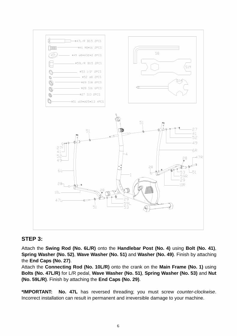
STEP 3:
Attach the Swing Rod (No. 6L/R) onto the Handlebar Post (No. 4) using Bolt (No. 41),
Spring Washer (No. 52), Wave Washer (No. 51) and Washer (No. 49). Finish by attaching
the End Caps (No. 27).
Attach the Connecting Rod (No. 10L/R) onto the crank on the Main Frame (No. 1) using
Bolts (No. 47L/R) for L/R pedal, Wave Washer (No. 51), Spring Washer (No. 53) and Nut
(No. 59L/R). Finish by attaching the End Caps (No. 29).
*IMPORTANT: No. 47L has reversed threading; you must screw counter-clockwise.
Incorrect installation can result in permanent and irreversible damage to your machine.
6

ATTENTION
The Right & Left Hinge Bolt (No. 47R/L) must fully penetrate the
nylon ring inside the pedal arm joint and the cranks. This will ensure
the stability and durability of your Elliptical Trainer.
In order to install hinge bolt properly, keep it perfectly straight as the
bolt goes through the pedal arms and the crankshaft. If the hinge bolt
is connected to the crankshaft at an angle, damage to both the hinge
and the crankshaft may occur.
If you have trouble connecting this part, try this alternate assembly suggestion:
Diagram 1:
Disconnect the Connecting Rod (No.
10L/R) from the Link Connector
Combination (No. 11L/R).
Diagram 2:
Insert the Locking Bolt (No. 47L/R)
through the hole of the Link Connector
Combination (No. 11L/R) then screw
the Locking Bolt No. 47L/R) into the
Crank Arm (No. 37).
*Remember when assembling the Left
side, you must screw the Locking Bolt
counter-clockwise to tighten. Connect
the Spring Washer (No. 53) and Nut
(No. 59L/R), and attach the End Cap
(No. 29), as seen in the Diagram on
Page 5. You can now reattach the
Connecting Rod (No. 10) to the Link
Connector Combination (No. 11).
7

STEP 4:
Insert the Handlebars (No. 5L/R) into the corresponding Swing Rods (No. 6L/R) and lock
using Knob (No. 30). Finish off by attaching the End Caps (No. 27).
8

STEP 5:
Attach the Pedals (No. 12L/R) onto the Connecting Rod (No. 10L/R) with the Bolts (No.
44), Washers (No. 50) and Nuts (No. 58).
9
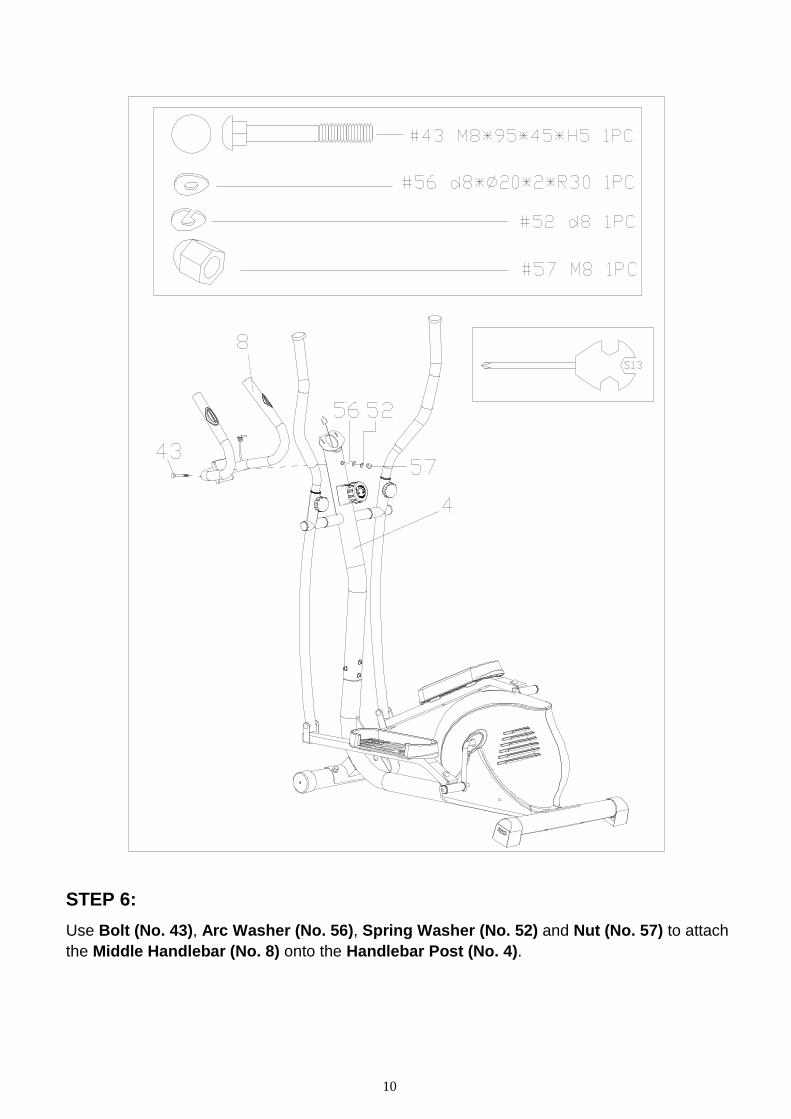
STEP 6:
Use Bolt (No. 43), Arc Washer (No. 56), Spring Washer (No. 52) and Nut (No. 57) to attach
the Middle Handlebar (No. 8) onto the Handlebar Post (No. 4).
10

STEP 7:
Connect the wire of Computer (No. 13) with Trunk Line (No. 14).
Secure Computer (No. 13) onto the Handlebar Post (No. 4) with Screw (No. 17) then
insert Hand Pulse Wire (No.16) into the hole on the back of Computer (No. 13).
The assembly is now complete!
11

EXERCISE INSTRUCTIONS
Using your elliptical bike will provide you with several benefits. It will improve your physical fitness,
tone your muscles, and in conjunction with a calorie controlled diet, help you lose weight.
WARM-UP PHASE
The purpose of warming up is to prepare your body for exercise and to minimize injuries. Warm up
for two to five minutes before strength-training or aerobic exercising. Perform activities that raise
your heart rate and warm the working muscles. Activities may include brisk walking, jogging,
jumping jacks, jump rope, and running in place.
STRETCHING
Stretching while your muscles are warm after a proper warm-up and again after your strength or
aerobic training session is very important. Muscles stretch more easily at these times because of
their elevated temperature, which greatly reduces the risk of injury. Stretches should be held for 15
to 30 seconds.
Remember to check with your physician before starting any exercise program.
COOL-DOWN PHASE
The purpose of cooling down is to return the body to its normal or near normal, resting state at the
end of each exercise session. A proper cool-down slowly lowers your heart rate and allows blood
to return to the heart.
12

EXERCISE COMPUTER
FUNCTIONAL BUTTONS:
MODE: Press to select functions.
Press and hold the MODE button for 3 seconds to reset time, distance and calories.
SET: (if available) Press to set values of time, pulse, distance and calories when not in scan
mode. Press the MODE button to cycle through functions. Use the SET button to set a value
for time, distance or calories. The value of a function will be set on a countdown. Press the
MODE button once more to set the function value you’ve inputted.
RESET: (if available) Press to reset time, pulse, distance and calories to zero when not in scan
mode.
FUNCTIONS:
1. SCAN: Press MODE button until “▼” appears at SCAN position (or until “SCAN” appears),
the computer will rotate through all 5 functions: Time, Speed, Distance, Calories and Total
Distance. Each display will be held for 6 seconds.
2. TIME: Counts the total time of the exercise from start to finish.
3. SPEED: Displays the current speed.
4. DISTANCE (DIST): Counts the distance of an exercise from start to finish.
5. CALORIES (CAL): Counts the amount of total calories burned during an exercise from start
to finish.
6. TOTAL DISTANCE (ODO): Counts the total distance after installing the batteries.
7. AUTO ON/OFF & AUTO START/STOP: If the wheel is put into motion, or any button is
pressed the computer will become active, and shall remain active while either of these two
things continue to be done, however without any signal for 8 minutes, the power (computer), will
turn off automatically.
8. PULSE RATE: (if available) Press MODE button until “▼” appears at PULSE position, (or
until “ ” appears). In order properly measure your pulse rate, you must place both your palms on
the contact pads located on the handlebar next to the seat, once you have done this the
computer will show your current heart beat rate in beats per minute (BPM) on the LCD after 3~4
seconds. Remark: During the process of “pulse measurement”, as a result of the contact
jamming, the measurement value may be higher than virtual pulse rate during the first 2~3
seconds, after which it will return to normal level. To ensure testing accuracy, it is suggested
that user test pulse during stop/pause exercise to avoid any possible influence. The
measurement value cannot be regarded as the basis of medical treatment.
9. ALARM: The functions of time, distance, and calorie can be set to countdown, if any of the
above value goes to zero, the computer will go off for 15 seconds.
Press MODE to select the function, then press SET to adjust the value.
NOTE: The computer containing only the “MODE” button does not have the alarm function.
13

SPECIFICATIONS:
FUNCTION
Auto Scan Every 6 seconds
Running Time 00:00 ~ 99:59 (Minute:Second)
Current Speed
The max pick-up signal is
999.9KM/H or MILE/H (or
9999RPM)
Trip Distance 0.0 ~ 999.9 KM or MILE
Calories 0 ~ 9999 Kcal
Total Distance 0 ~ 9999 KM or MILE
Pulse Rate 40-240BPM
Battery Type 2 pcs of SIZE AAA
Operating Temperature 0℃ ~ +40℃(32℉~ 104℉)
Storage Temperature -10℃ ~ +60℃(14℉~ 140℉)
14