Magnetic Coupling (gasket design) General Assembly ......Rexroth Chemical series Variable...
16
1 Magnetic Coupling (gasket design) General Assembly Instructions Rexroth Chemical series Variable Displacement Pump
Transcript of Magnetic Coupling (gasket design) General Assembly ......Rexroth Chemical series Variable...

1
Magnetic Coupling(gasket design)
General Assembly InstructionsRexroth Chemical series
Variable Displacement Pump

2
o-rings
bellhousing
cooling flange
inner drivenmagnet
canister
outer magnetic drive& motor hub
motor flange
intermediate pump shaft
Coupling Components
pump flange
gasket hardware

3
1. Clean out pump flange to make sure all metal shavings are removed.
2. Make sure all other parts are free from debris.

4
1. Remove the seal cartridge from the pump.
Note: The sleeve bushing can be removed if proper tools are available.

5
1. Position the gasket on the pump.
2. Tighten the pump flange to the pump squeezing the gaskettight. Use standard torque specs for the screws used.

6
1. Insert o-ring on the inside groove between the pumpand cooling flange
2. Slide the cooling flange over the pump flange andsecure using 6 socket head cap screws.
* this is the 2nd static seal
7
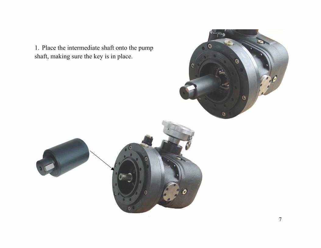
1. Place the intermediate shaft onto the pumpshaft, making sure the key is in place.
8
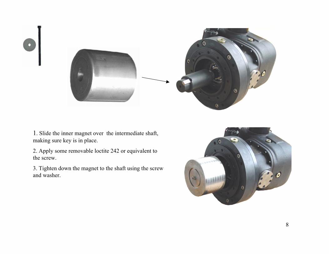
1. Slide the inner magnet over the intermediate shaft,making sure key is in place.
2. Apply some removable loctite 242 or equivalent tothe screw.
3. Tighten down the magnet to the shaft using the screwand washer.

9
O-ring groove
1. Place o-ring in the groove (shown below)
2. Slide the canister over the inner magnet, makingsure that the o-ring is properly seated.
3. Tighten down with socket head screws.
* this is the 3rd and final static seal

10
1. Plug all of the ports on the pump.
2. Pressurize the cooling ports with 30 – 50 psi of air pressure. Make sure that thepressure holds for at least 30 minutes. This is done to assure that there is no leakage inthe seals.
11
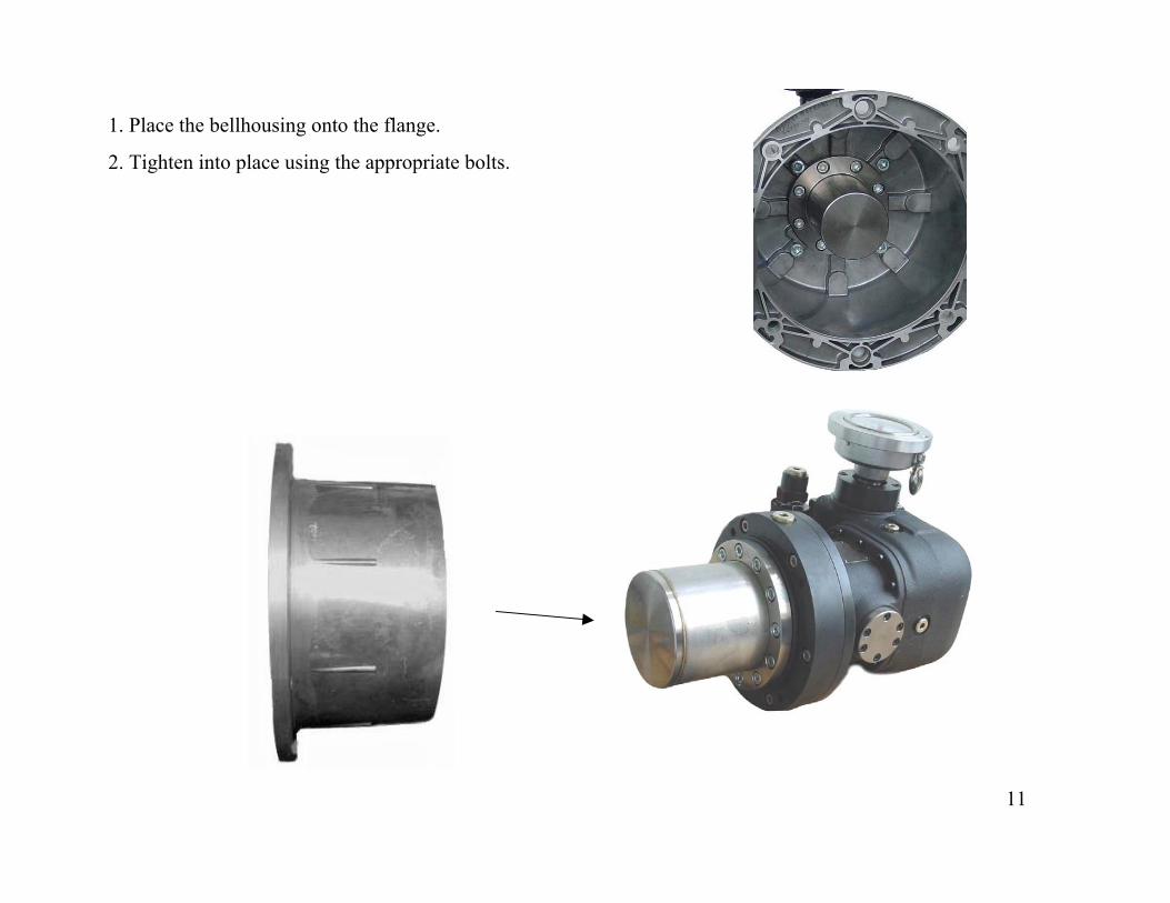
1. Place the bellhousing onto the flange.
2. Tighten into place using the appropriate bolts.

12
1. Slide the outer magnet onto the motor shaft, making sure the key is in place. Theend of the pump shaft should then be flush with the magnet hub.
2. Tighten the hub using the set screws in the hub.
Outer shaft flush with motor hub.

13
1. Place motor flange on the motor. Only socket head screws can be used to tighten in place.

14
1. Align the 2 assemblies and carefully bring them together.Make sure fingers are not between the bellhousing and motorflange.
2. The magnetic force will naturally pull the 2 together. Oncethey are close it will be necessary to resist the magnetic forcea little in order to keep the bellhousing from slamming intothe motor flange.
3. Align the holes and tighten bellhousing to mag flange.
WARNING!KEEP FINGERS AWAY

15
1. Remove the plug closest to the motor.
2. Back off the set screws in the motor hub. This allows the hub to slide into its natural position.Note: The hub may not move at all.
3. Tighten the set screws.
access / inspection hole

16
Assembly complete!