Magnetic Amplifier for Power Flow Control - ARPA-E | · PDF file ·...
14
Magnetic Amplifier for Power Flow Control Aleksandar Gylfi Fred Kevin Jeffrey Dimitrovski Olafsson Wang Tomsovic Hildreth GENI Annual Meeting New Orleans, LA, January 15, 2015 SPX TRANSFORMER SOLUTIONS, INC.
Transcript of Magnetic Amplifier for Power Flow Control - ARPA-E | · PDF file ·...

Magnetic Amplifier for Power Flow Control
Aleksandar Gylfi Fred Kevin Jeffrey
Dimitrovski Olafsson Wang Tomsovic Hildreth
GENI Annual Meeting
New Orleans, LA, January 15, 2015
SPX TRANSFORMER SOLUTIONS, INC.

SPX TRANSFORMER
SOLUTIONS, INC.
MAPFC
Project Objectives
1
‣ Develop simple, robust, and efficient power flow control device (CVSR) based on magnetic amplifier principle
‣ Build transmission-level prototype for field demonstration, based on design and testing experiences from laboratory prototypes
‣ Conduct system integration and benefit studies to prepare for system-wide deployment
‣ Expand the functionality of the device beyond steady state operation (damp low-frequency oscillations, limit fault currents)
RELIABLE
• Novel use of existing
technologies
• Magnetic field used as
control medium
HIGH PERFORMANCE INNOVATIVE
• Large continuously
variable reactance
• Cost-effective for full
power flow control
• Simple construction
• Electrical isolation
between power and
control circuits

SPX TRANSFORMER
SOLUTIONS, INC.
MAPFC
Transmission-level Prototype
2
Completion of the design and building
of a 115kV, 1500 A CVSR to be
installed for field demonstration
Device Testing
Simulation
Conducted two factory tests to validate
parameters and performance of the prototype
Improved FEA simulation by using a
new approach to create reliable mesh
for strong nonlinear magnetization
AC
Excitati
on
Mesh #1 Mesh #2
Mesh #3 Mesh #4
SPX TRANSFORMER
SOLUTIONS, INC.
MAPFC
3
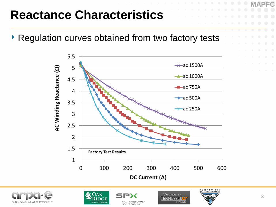
‣ Regulation curves obtained from two factory tests
1
1.5
2
2.5
3
3.5
4
4.5
5
5.5
0 100 200 300 400 500 600
AC
Win
din
g R
eac
tan
ce (Ω)
DC Current (A)
Factory Test Results
ac 1500A
ac 1000A
ac 750A
ac 500A
ac 250A
Reactance Characteristics
SPX TRANSFORMER
SOLUTIONS, INC.
MAPFC
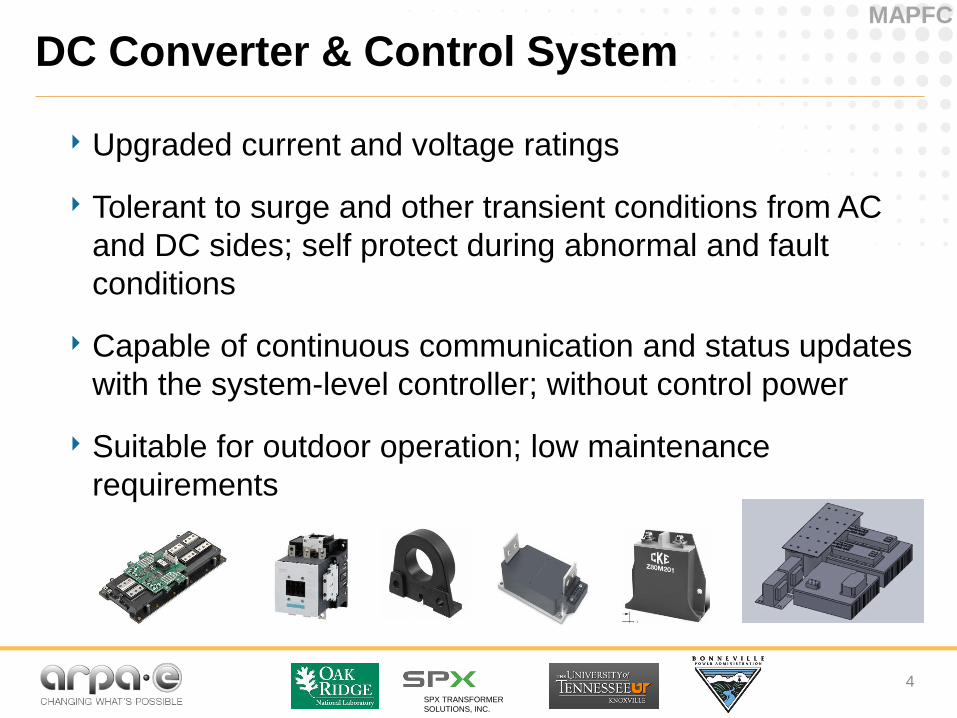
DC Converter & Control System
‣ Upgraded current and voltage ratings
‣ Tolerant to surge and other transient conditions from AC
and DC sides; self protect during abnormal and fault
conditions
‣ Capable of continuous communication and status updates
with the system-level controller; without control power
‣ Suitable for outdoor operation; low maintenance
requirements
4

SPX TRANSFORMER
SOLUTIONS, INC.
MAPFC
Focus on meeting the performance requirements. Three versions of hardware:
1) Use a down scaled lab DCC (HW1) system based on commercial products to develop software, control and protection (development complete, in use for control software and hardware testing)
2) Build a full scale DCC (HW2) for factory testing focusing on operation functionalities (under assembly and testing)
3) Build the full converter system (HW3) for field commissioning in 2015 with all functionalities and capabilities (started on key cooling and enclosure design, may need adjustments based on HW2 testing)
DC Converter Strategy and Status
5

SPX TRANSFORMER
SOLUTIONS, INC.
MAPFC
DC Converter Development
HW1 Lab Test Setup HW2 Busbar Assembly
HW2 Gate Drive and Interface
Boards under Test
6

SPX TRANSFORMER
SOLUTIONS, INC.
MAPFC
Field Demonstration
7
‣ Finishing the factory tests for the reactor
‣ Completion of the DCC
‣ Integration of the reactor control
system and DCC
‣ Installation and conducting the
field test/operation
BPA’s Sacajawea S/S
Walla Wall Co, WA

SPX TRANSFORMER
SOLUTIONS, INC.
MAPFC
What has been done and learned?
8
Concept Validation
Theoretical
Simple model to initially validate the idea
FEA simulation used to understand the nonlinear operation and design the prototype
Practical
Four laboratory-scale prototypes designed, built and tested to help achieve different research goals
A single-phase transmission-level prototype designed, built and tested to prepare for field demonstration
Approach Iterative
FEA
Co-simulation
Test

SPX TRANSFORMER
SOLUTIONS, INC.
MAPFC
Grid Integration - Benefit Study
9
‣ Congestion relief under certain power system contingencies
‣ Shift power from overloaded lines to the underloaded path
outage
No. of lines Pre-
contingency
Post-
contingency
Optimization
(kf=5)
1 93.78% 105.65% 100%
2 92.30% 103.19% 100%
3 91.87% 103.19% 99.34%

SPX TRANSFORMER
SOLUTIONS, INC.
MAPFC
Technology-to-Market
10
‣ Exclusive license to SPX/Waukesha TS
‣ Commercial Product Initiative – 7 stages
– Statement of needs
– Validation of needs
– Plan and approval
– Product design and validation
– Operational readiness
manufacturing
– Commercial readiness
– Release and audit
SPX TRANSFORMER
SOLUTIONS, INC.
MAPFC
Post ARPA-E Goals
‣ Promote large-scale deployment of CVSR through system
benefit studies
‣ Facilitate the commercialization through development of
installation & operation procedures and training materials
‣ Investigate additional capabilities of the device with different
control schemes (“firmware upgrades”)
‣ Improve further the design for a smaller, lighter, and cheaper
unit (“hardware upgrades”)
11

SPX TRANSFORMER
SOLUTIONS, INC.
MAPFC
Conclusions
‣ Factory tests help further understand the operational
characteristics of the CVSR and prepare for the field
demonstration
‣ Iterative modeling-simulation-testing process improved
the device and the models
‣ Three hardware generations of the DC converter and
control system
‣ Initial benefits in congestion relief, other applications
to follow
‣ Exclusive manufacturing by SPX/Waukesha TS
12

Thank You!
This endeavor would not have been
possible without the support from