September 19/20, 2007 SIS 100 Magnet cooling and cryogenic distribution.

Magnet Test LabCryogenic System
MTL
SuperconductingSuper ColliderLaboratory
SSCL-N-877September1994Distribution Category:400
V. Garini
UCtCt

SSCL-N-877
Magnet Test Lab MTL Cryogenic System
V. Ganni
SuperconductingSuperCollider Laboratory*
2550 BeckleymeadeAve.Dallas, TX 75237
September1994
Operatedby the UniversitiesResearchAssociation,Inc., for the U.S. Departmentof EnergyunderContractNo. DE-AC35-89ER40486.

TABLE OF CONTENTS
1. Introduction
2. General Over View of Helium RefrigerationandLiquefaction Systems
3. Details of MTL Cryogenic System
4. OperatingModes and Control Philosophy of MTLCryogenic System
5. Flow Diagrams for Various Operating Modes
6. Design Verification of the Refrigeration System

1. INTRODUCTION
The MTL Cryogenic System is the most sophisticated and automatedhelium refrigeration system ever built by Industry in this country. It isbuilt by Process Systems, Inc. of Westborough, Massachusetts.
This system is designed to SSCL specifications with full cooperationin design between the lab and the industry. Its capabilities include thecapacity to provide supercritical helium at varying pressure levels, flowrates and temperatures up to 2.5 K to the load and supported by an highefficient helium refrigeration system. In addition, it has the capability ofhandling various magnet conditions of cleaning, cool down, warm-up andmagnet quench upsets.
This MTL Cryogenic System is efficient, flexible, reliable with manylevels of redundancy for continuation of operation even when there areproblems with some sub systems.
The various presentations made at different times by the members ofthe cryo engineering group of the cryogenics department are compiled inthis document. This is the first draft of the compiled material and mayrequire a revision in the future.

2. GENERAL OVER VWW OF HELIUM
REFRIGERATION
AND
LIQUEFACTION SYSTEMS

WHAT IS A REFRIGERATOR?
THE REFRIGERATORIS A SYSTEM WHICH TRANSFERSHEAT FROM
LOW TEMPERATURETO HIGH TEMPERATURE. NORMALLY THE TERM
REFRIGERATION IS USED FORABSORBING HEAT AT CONSTANT
TEMPERATUREFROM A LOAD.
THE INPUT POWERREQUIREDTO THESESYSTEMSMAINLY DEPENDSUPON:
1. THE TEMPERATUREFROMWHICH HEAT IS EXTRACTED.
THIS IS THE LOAD TEMPERATURE
2. THE TEMPERATUBE TO WHICH THE HEAT IS REJECTED.
TilLS IS THE AMBIENT ENVIRONMENT TEMPERATURE
3. Tilt PROCESSUSED
Eg: A. VAPOR COMPRESSIONPROCESS
B. HAMPSON PROCESS
C. CLAUDE PROCESS
4. THE EFFICIENCY AND EFFECTiVENESSOF THE COMPONENTSUSED
Eg: A. COMPRESSORS
B. EXPANDERS
C. HEAT EXCHANGERS
5. HOW WELL THE REAL COMPONENTSMATCH TO TIlE PROCESS
6. HOW THE SYSTEM IS CONTROLLED

EFFICIENCY:
THE SIMPLE DEFINITION IS THE RATIO OF THE USEFUL ENERGY TO TIlE
REQUIRED ENERGY FORTHE PROCESS.
IT IS ONE OF THE MOST COMMONLY USED TERMS AND OFTEN
MISUNDERSTOOD. MAKE SURE THE COMPARISONSARE BASED ON THE
SAME QUALITY OF THE REQUIREDENERGY
Eg. of Quality: APPROXIMATELY 3KWH OF THERMALENERGY IS REQUIRE
TO PRODUCE1KWH OFELECTRICAL ENERGY.
LET US START WITH AN IDEAL REFRIGERATIONCYCLE
TIlE CARNOT REFRIGERATIONCYCLE:
0
1. COMPRESSOR
2. CONDENSER
3. EXPANDER
4. EVAPORATOR
GAS IS COMPRESSEDISENTROPICALLY.
HEAT IS REJECTEDISOTHERMALLY T2
GAS IS EXPANDED ISENTROPICALLY.
HEAT IS ABSORBED ISOTHERMALLY Ti
COEFFICIENTOF PERFORMANCECOP:
COP=USEFUL REF1UGERATION
WORK INPUT
Eg.: COP OF A REFRIGERATOR=
Ti
fl-Ti
460+0
460+100-460+0
i.e 1KW OF INPUT POWERWILL PROVIDE 4.6KW OF COOLING
I
Vm
QLDV/
S
=4.6

LET US LOOK AT A FREON REFRIGERATORWITH REAL COMPONENTS:
I
1. COMPRESSOR
2. CONDENSER
3. JT VALVE
4. EVAPORATOR
GAS IS COMPRESSEDADIABATICALLY.
ADIABATIC Eu. - 80 %
HEAT IS REJECTEDWITH A DT
GAS IS EXPANDED ISENTHALPICALLY.
HEAT IS ABSORBED WITH A DT
IN ADDITION CONTROLDEVICES ARE USED FOR
Eg.: A JT VALVE CONTROL
B COMPRESSOR& MOTOR CONTROLS
C PRESSURE,TEMPERATURE,FLOWAND LEVEL CONTROLS
A REFRIGERATOR WIT!! REAL COMPONENTSWORKING UNDER THE ABOVE
CONDITIONSREQUIRE-1.5KW OFINPUT POWERFOR4.6KW OF COOLING.
=
-----=66%
CARNOT EFFICIENCY TELLS YOU HOW WELL YOUR SYSTEMIS WORKING
WITH RESPECTTO THEORETICALLY POSSIBLEMAXIMUM EFFICIENCY.
IT IS ONE OFTHE VERY GOODMEASURESFOREVALUATING DIFFERENT
SYSTEMSAND FORCOMPARING THEM IN VARIOUS MODES.
CARNOT EFF.IDEAL WORK i
ACTUAL WORK 1.5
S

HELIUM REFRIGERATOR
THE REFRIGERATORIS A SYSTEM WHICH TRANSFERSHEAT FROM LOW
TEMPERATURETO HIGH TEMPERATURE.NORMALLY THE TERM
REFRIGERATIONIS USED FOR ABSORBING HEAT AT CONSTANT
TEMPERATUREFROM A LOAD.
A HELIUM REFRIGERATORABSORBS HEAT ENERGYAT 4K AND TRANSFERS
IT TO AN AMBIENT ENVIRONMENT.
HELIUM LIOUEFIER
THE LIQUEFIER IS ALSO A SYSTEM WHICH TRANSFERSHEAT FROM LOW
TEMPERATURETO HIGH TEMPERATURE.THE TERM LIQUEFACTION IS USED
FORTRANSFERRINGTILE HEAT FROM A RANGE OF TEMPERATURES.
TO LIQUEFY HELIUM THE IIEAT ENERGYIS TRANSFERREDFROM HELIUM
GAS OVER A TEMPERATURERANGEOF 300K -4K TO AN AMBIENT
ENVIRONMENT.
THE REFRIGERATIONTO BE PROVIDED BY THE SYSTEM FOR:
1. THE EXTERNAL LOADS eg.: Refrigeration,liquefaction
2. THE HEAT EXCHANGER LOSSES
3. ThE STATIC HEAT LEAK

V
4-
E4,I-.
Table 3.2. Maximum inversionternpencure
. MaximumInversion
Gas
Tern pera lure
K
Helium-4 45 81Hydrogen 205 369Neon 250 450
Nitrogen 621 IllSAir 603 1085Carbon monoxide 652 1174Argon 794 1429Oxygen 761 1370Methane 939 1690Carbondioxide 1500 2700
Ammonia 1994 3590
Pressure p
Joule-ThompsonEffect

Conipessor
a 6
The thermodynamicallyideal liquefactionsystem.
Fluid
HeliumHydrogenN eonNitrogenFluorineArgonOxygenMethane
Obtalned bythe fluid.
T RefrigerationK WIW
LiquefactionW hr/liter
Evaporating LiquidReirlgeratlon W/W
4.2 70.4 236 32620.4 13.7 278 31.727.1 10.1 447 15.577.4 2.88 173 3.8785.0 2.53 238 3.2687.3 2.44 185 2.9590.2 2.33 195 2.89
111.5 1.69 129 2.15
‘It
T
Vt
SLiquid reservoir
dividing the ideal liquefaction power requirement by the heat of vaporization of

3. DETAILS OF MTL CRYOGENIC SYSTEM
Previously Presended as
TIM #11
MTLI ASST/ NiS REFRIGERATORLIQUEFIER
ASST CRYOGENIC SYSTEM
MTL CRYOGENIC SYSTEM
NOVEMBER 61991
Roberto Than
Cryogenics Group
Cryo-Engineering Section

MAGNET TEST LAB CRYOGENIC SYSTEM
MTL/ASST/N15 Refrigerator/LiquefierSystemMain CompressorSystemColdBoxWarm Gas StorageLHe Dewar System
Cleaning, Cooldown, Warm-up, and Purification SystemCCWP ColdBox, Dehydration Unit, RegenerationUnitCompressorSystem
Refrigeration RecoverySystem
PumpBox
5 Distribution Boxes
5 Test stands
LN2 system for shield cooling and 300K-80K precooling
ASST CRYOGENICSYSTEM
MTL/ASST/N1S Refrigerator/Liquefier System-Main CompressorSystem-ColdBox-Warm Gas Storage-LHe Dewar System
Cleaning,Cooldown,Warm-up,and PurificationSystem-CCWP ColdBox, Dehydration Unit, RegenerationUnit-CompressorSystem
PumpBox: Functionascold compressorCooling<4.5K

{t p
S
cm
cn-1
tcj
3;,-1-4
Cz
z mc m

MAINC ElM P PE S SURSYSTEM
DR1TIDN
LIQUEFIERREFRIGERTLRCOLD BOX
ccvP
PUMP BOXA5
COLO COUP
LN2LINES
ASST CRYOGENIC SYSTEM

I
t
2 A ala’-AQ1ViURV1 j1iTEo
a3dflS ONII3flONODaJdflS
Ut
xot ,onnflufla
L
a KIW’LT
ro CTCLJj
ii
=iLiL_____- a
F
d4u1u
-Ut
LAJ4I
I.
IC
LI
L
* 2
-.L_La-
L
c-S--- 3
fof
U
-t
III I
I.
-cia
‘I
Ut
AT
El
LIt_ IX
i-I__ I
IL
a-s
I____
a-.2.
*---
tb
%‘a. a.
Sn
I
Ut
a
r- -rC
6l
C

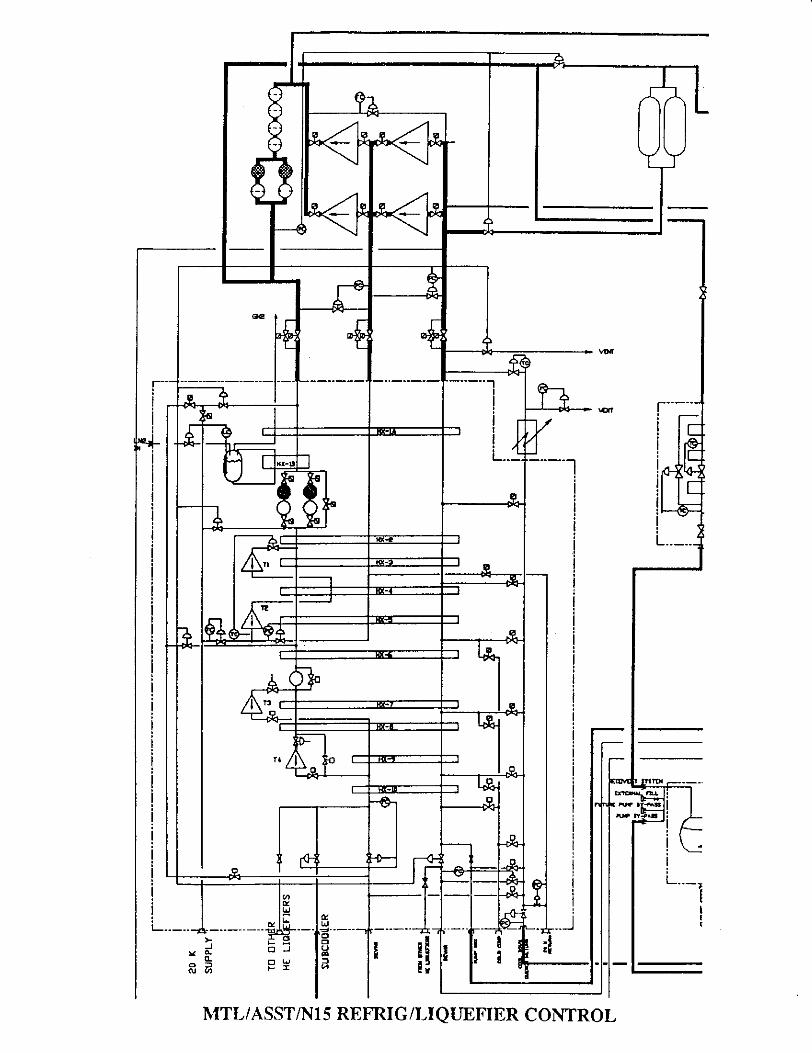
MTL/ASST/N15REFRIGERATOR/LIQUEFIER
CYCLE: 3 Pressurelevel cycle with 4 Expanderswith the top two inseriesandthe bottomtwo in a Kundig’s cold endarrangement.
CAPACITY:
Design:2200W cooling @ 4.4 K and 22 gls liquefactionload5O%R/5O%L with 30 gls compressorbypass.
MaximumRefrigerationof 3500W with 30 gls compressorbypass.
MaximumLiquefactionof 37 gls with 30 gls compressorbypass.
Equivalentsizeof 4.4 KW of Refrigerationat4.4K
Idealwork is the minimumwork requiredto providea certainamountof cooling at a particulartemperaturelevel. The lower thetemperatureat which cooling hasto be provided,themoreworkrequired.
According to the secondlaw of thermodynamics,for isothermalcoolingat4.4 K the ideal work requiredis about67.7 W per W of coolingpower.
For a real systemthe actual work requiredis morethanthe ideal workrequired. Definean efficiencybasedon 2nd law of thermodynamicscalled the Carnotefficiency:
Ideal WorkCarnotEfficiency =
Actual Work
Hencethe Carnotefficiencytells you how well the real systemperformsrelativeto an ideal system.

For the MTL/ASST Refrigerator/Liquefierthe ideal work requiredisabout298 kW. The powerinput to the compressorsis about1360 kW.
Ideal Work 298 kWCarnotEfficiency = - = = 22.0%
Actual Work 1360 kW
CarnotEfficiency of the MTL/ASST R/L: 22-23%
SpecificPowerConsumption: 300W/WWatts of compressorwork per Watt of cooling @ 4.4K
Actual Work 1360 kWsit =
-
Cooling Power 4.4 kW
OTHER REFRIGERATORSILIQUEFIERS
PLANT Specific CapacityPower @ 4.4KConsumption Refrigeration
HERA RIL 281 W/W 10.7 kWCERN 6KW R 230 W/W 6 kWFERMI CL* 210 WRY?? 15 kWMTL/ASST R/L 309 WIW 4.4 kWCERN 18kW 220 W/W 18 kW
* ReciprocatingCompressors.All othersoil floodedsrewcompressors.

COMPRESSORSYSTEM
TYPE: OIL FLOODED ROTARY SCREWCOMPRESSOR
2 FIRsTSTAGE COMPRESSORSSULLAIR C2SLBROTORDIAMETER: 255MM
2 SECONDSTAGE COMPRESSORSSULLAIR C2SMAROTORDIAMETER: 255 MM
BULK OIL SEPARATOR
FOUR4 STAGE COALESCERSandCHARCOAL ADSORBERSBEDS
Frame MotorSize
L/DRotor
Psuctionbar
Pdischrgbar
Flowrateg/s
1 stage C2SLB 250 H.P. 1.7 1.05 2.2-3.3 113
1 stage C2SLB 250 H.P. 1.7 1.05 2.2-3.3 113
2 stage C2SMA 700 H.P. 1.25 2.1-3.2 19.5 225
2 stage C25MA 700 H.P. 1.25 2.1-3.2 19.5 225

COMPRESSORSYSTEM
1’

Fig, iFEMALE ROIOP.
SCREW COMPRESSON
SINGLE STAGE
* Gas as it is pulledinto chamber.
* Compressed gas.
F. CooUng oil.
DRIVE SHAFT
DISCHARGE: At eCt’rnned chambt,o’arne. he ,xede.rast o,T us eo,edar he co,no,e,ied a,1 isch.ged.
© naa M.co Co*po,.i,o&
AJ
SUCTION: As screw ,olon total.. gas pulled into the ch,mben as hercavity ,ize nctnu until muInum volume is irtained then salated by heflied sucuon past
SUCTION Ijon. he Chamber, a,t teduced inCOMPRESSION: AS sc,ew’otoi,cc,rme’ota.
IT eiIeci’n compress,onal he cat.
o iiide valve tip. Both ubricjt’ng oilsoling ol hq ce.r.nce, and Coohnt
MALE ROTOR

COLDBOX
Work extraction: Via 4 Fixed NozzleInward Flow Radial Expanders
Top 2 expandersarein series. High pressuregasis takenfrom the main streamat about40K andexpandedthroughTi to apressureof about 8 barandgoesthrougha heatexchangerbeforeit isfurther expandedin T2 and is returnedthroughthe mediumpressuresideof the cycle.
Thebottom 2 arein paralleland stagedat differenttemperature levels with all the flow going to the dewar/supplyKundig’s arrangement. The flow is then throttled through a J-Tvalve into the dewar.
4 DYNAMIC GAS BEARING EXPANDERS
No Wheel Design Eta Work Tin Pin Tout PoutDiameter Mode @ Output @ @
Design Design design design design designK bar K bar
Ti 28 mm Liguef 75% 10250 W 48.08 17.9 39.10 8.72T2 28 mm Liguef 78% 6850W 23.64 8.71 17.27 3.09T3 12 mm Refrig 61% 1090 W 12.51 15.83 8.45 4.00T4 12 mm Design 63% 980 W 8.61 16.79 6.22 4.00
HEAT EXCHANGERS: ALUMINUM PLATE-FIN
S HX CORESCORENO. HX. NO. Temp. level UA W/K NW1 1A 300K-80K 77000 432 2/3 80K-40K 30000 15/43 4/5 40K-1SK 35000 15/64 6/7/8 1SK-9K 23000 7/13/75 9/10 9K-SIC 15000 7/86 LN2 boiler lB 85K-78K 5000 3TOTAL 185000 128

r
-
Sr

*JoSK.
44K
IDEAL REFRIGERATOR
T
MTL/ASST REFRIGERATEIR
I
S
-4-4K
S

3ULAR’Cryogenic turboexpanderSelf-acting gas bearing system
Coolerconnection 9
a.
Coolerconnection1
compressorBrake
Cooling-waterConnectionShaft
Thrust bearing
Radial bearing
Speed sensor
Nozzle ring
Turbine wheel
Brake circuitfilter
t*
Magneticauxiliarybearing
+£

LIQUID HE STORAGEDEWAR SYSTEM
CAPACITY: 10,600GALLONSNitrogen shielded,1.25" multi layer insulation.
SUBCOOLER: To subcool supercritical Helium to the distributionboxeswhen the pump box is bypassed.
2 QUENCH HEAIERS: Quench return from magnetsFuture quench return
HEATER: To vaporize liquid.
Connections: Pump by-passExternal fillPump feedSupply lineVapor return lineFuture pump by-passTwo decantsfor liquid withdrawelFuture feed

LIQUID HELIUM STORAGEDEWAR SYSTEM
ECOVE I SYSTEM-I-
FL ru
EXTERNAL FILLD4
E PUMP BY-PASS
PUMP BY-lASS
LN2 GN2
IL
a
IC-aLiR
zI

PUMPBOX
FUNCTION: To circulatesuper-criticalHelium throughthedistribution boxesandmagnetteststands.
1 Make-upBoosterPump1.0 bar to 3.5 bar 200g/s
2 CirculatingPumps3.5 bar to 4.0 bar Total capacityof 500 g/s
Two 2 SurgeVessels:Temperaturegradient20K-4K in the top thirdof the vesselto providea compressionbuffer.Height: 90 inches.Diameter:16 inches.Volume: 11 ft3 300 liters:
1. Dischargesideof the circulatingpumps2. Dischargesideof the Make-uppumpand return from the magnets.
To smoothout the pressurewavescausedby the reciprocatingpumpsandto dampenedthe pressurewaveduring a quench.
ASST System:PumpBox is usedas a cold compressorto providecooling below4.SICThisis accomplishedby reducingthe vaporpressurein subcoolerbathof the distributionboxesby pumpingon itwith this cold pump.

PUMP BOX

APPROX r CM
st non C-E
0o0o0o30
TIIIIIIIIIIU.
L
z.
_____
r5.0’
SECTEON

REFRiGERATION RECOVERYUNIT
FUNCTION: TO PROVIDEREFRIGERATIONBELOW 4.5K
This is accomplishedby lowering the vapor pressurein the distributionboxes’ssubcoolerbath. The pressurein the distribution box ismaintainedby a parallelpair of vacuumpumpsin series.Eachseriesconsistsof two 2 centrifugalvacuumpumpsand a liquid ring vacuumpump. The liquid ring pump dischargesto thesuctionsideof themain first stagecompressors.
CAPACITY: 2 stands@ 2.5K Bath temperature2.4K,Bath Pressure0.082bar by VAC IHeatload S1W/ stand. Total: 102 WLeadcooling flow: 1 g/s/standCirculationflow: SO gls
3 stands@ 3.6K Bathtemperature3.5KBath pressure0.416bar by VAC IIHeatload51W! stand. Total: 153 WLeadcooling flow: 1 g/s/standCirculationflow: 100 g/s
VACUUM PUMPING SYSTEM2 PARALLEL SYSTEMS consisting
of the following pumpsin series
Psuction Pdischarge FiowrateVAC 1 2 Centrifugal
in series47 mbar 310 mbar 12.35gfs
VAC II Liquid RingPump
310 mbar 1100mbar 31.08gfs

REFRIGERATIONRECOVERY UMT
H
00C>

CCWPUNITS & AUX SKIDS
CleaningCooldownWarm-upandPurificationUnits
2 Units for the MTL, 1 for the ASST
COMPRESSORSYSTEM
80K PURIFICATION BEDS
BEAT EXCHANGERS COLDBOX
DEHYDRATION SKID
REGENERATIONSKID
GAS STORAGESYSTEM
CCWPCOMPRESSORSKID
2 Compressorsarrangedin parallel. With an Oil RemovalSystemDesignFlowrateper Compressor:55.4 g/s@a suctionpressureof 2 bar Motor size: 125 HR
HEAT EXCHANGERS300K -80K heatexchangercoreanda small nitrogenboiler heat
exchanger
80K PURIFICATION BEDSRemovesresidualgassesandothercontaminantsfrom thehigh
pressureHelium flow.
DEHYDRATION SKIDRemovesmoisturefrom the return flow.
REGENERATIONSKIDRegeneratesthe 80K PurificationBeds

CCWPCONT’
Cleaning: Warm cleanHelium gasis sendto the magnetsandreturnedto the CCWPunit. Mainly moistureis removedfrom themagnets. On the way backto the compressorthe flow goesthroughthe dehydrationunit wherethe moistureis removed.
Cooling: Cooling from 300K to about80K is providedby circulatingHelium that is cooledthroughheatexchangewith LN2 throughthemagnetsystem.
Warmup:Warmupis accomplishedby circulating warm Helium gasthroughthe magnets.
Purification: Gas suppliedto the magnetshasto be clean. The heliumfrom thecompressordischargegoesthroughan oil removalsystemandduring cooldownthe 80K adsorberbedsremovesnitrogenandothercontaminantsthatcan be removedat thosetemperaturesfrom theHelium. The remainingresidualgasseswill be removedin the mainrefrigeration/liquefiercoldboxwhenthe magnetsare further cooleddown.
OPERATINGMODES CCWP
MODE Flow Rate Supply
TemperatureCleanup 15 gls 300K
Cooldown 80 gls 77K - 300KWarmup SO gls 300K
Purification 10 gfs 300K

REGENERATION SKID
DEHYDRATION SKID
I
CO
CU

CC’½’P
tEED
CCWP COLD BOX

DISTRIBUTION BOX
FUNCTION: Acts asthe intefacebetweenthe refrigerator,refrigerator’ssubsystemsCCWP,RefrigerationRecoveryUnit, andPumpBox and providesthe subcoolingbelow 4.5K.
Connectionsto RefrigerationRecoveryUnit
Crossconnectionsto the CCWP Units.
Connectionswith LN2 system.
Connectionsto and from PumpBox andDewar
Heatexchangerandsubcooler/phaseseparator.
The supplystreamis cooledby the returnstreamfrom the magnetsinthe heatexchangerand furthersubcooledin the bathheatexchanger.

-----S
-__
P
-4’
-tWI
C,
ziciDi
DISTRIBUTION BOX
1
GN2 LN2

1HI I
-l
C,,-4
C1
Cz
C>c
DISTRIBUTiON BOX & TEST STAND

MTL/ASST/N1SREFRIGERATOR/LIQUEFIERCONTROL PHILOSOPHY
The Refrigerator/Liquefieris controlledby 8 eight Primarycontrolloops.
ControlledVariable Control Device ControlMethod I Mode
Suctionpressuretofirst stagecompressor
By-passvalveLow Pressurestage
Constantcontrolabout1.05 barlow
Suctionpressuretosecondstagecompressor
By-passvalveifigh Pressurestage
Limiting function2.7bar low
High pressuresupplyto coldbox fromcompressor
Make-upvalvestoand from buffertanks
Constantor Limiting18.5bar high
Outlet temperatureofexpanderT2
Inlet valvetoexpanderTi
Limiting function15.0K low
UpstreampressureofJ-T expansionvalve
J-T valve todewar/subcooler
Constantcontrol4.0 bar low
Pressureof the lowpressurestreamtothe lastheatexchanger
Control valve onvaporreturn lineLP from dewar.
Limiting function1.2 bar low
Capacityof expanderexpanderT3 underpart toadconditions
Inlet valve toexpanderT3Maintainsvalve’supstreampressurethrottleT3
Limiting function12 bar
LN2 level in LN2phaseseparatorforHX-1B
LN2 feedcontrolvalve
Constantcontrol75 % Iiq. level
-J0-
aCu
CU
MTL/ASST/N15 REFRIG/LIQUEFIERCONTROL

With the currentcontrol philosophythe plant can adaptitself easilytothe load change.
At a setsupply pressurefrom the compressorshigh pressuredischargethe plant capacitybalancecanvary betweenlull liquifactionandfull refrigeration. If the load is lessthan thecurrentcapacity,theliquid level will rise in the dewar. If the load is higher thanthecurrentsettingthe level in the dewarwill drop.
The plant can be madeto float with the load by closingthe gasstoragebuffer to the low pressureside lst.stagesuction. In this situationifthe load increasesthe low pressurereturn flow increases,leading to anincreasein the flowrate throughthe secondstagecompressorsand anincreasein the dischargepressureresulting in an increaseof the plant’scapacity. If the load decreasesthe low pressurereturn flow decreases,resulting in an decreaseof the secondstagedischargepressure.

4. OPERATING MODES
AND
CONTROL PHILOSOPHY OF
MTL
CRYOGENIC SYSTEM

To be publishedasan addendumin SuperCollider 5 SSCL-Preprint-501
OperationalModesandControlPhilosophyof theSSCLMagnetTestLab. MTL CryogenicSystem*
V. Ganni, R. Than,andM. Thimmaleshwar
SuperconductingSuperCollider Laboratory2550BeckleymeadeAve.
Dallas,TX 75237
May 1993
Presentedat theFourthAnnual {nternationalSymposiumon the SuperCoIlider,March 4-6, 1992, New Orleans,Louisiana.
toperatedby the UniversitiesResearchAssociation,Inc., for theU.S. Departmentof EnergyunderContiactNo. DE-AC35-39ER40486.

OPERATIONAL MODES AND CONTROL PHILOSOPHY OF THE SSCL MAGNETTEST LAB. MTL CRYOGENIC SYSTEM
V. Janni,R. Than. NI. Thinjmaleshwar
SuperconductingSuperCollider Labontoryt2550 BeckleymeadeDallas. TX 75237.USA
INTRODUCTION
The MTLs function is to testprototypeandindustrially manufacturedmagnetsfor the SuperconducdngSuperCollider Laboratory SSCL. The cryogenic systemof the MTL has a main refrigeration systemconsistingof a two-stagecompressionsystem,a refrigerator/liquefiercotdbox,a liquid helium dewar.wazmgas storage,and a regenerationskid. The MTL cryogenic system also ipcludes the following auxiliaryequipment: two ceaning.cooling.warmup andpurification CCWP cotdbox moduleswith a regenerationskid for the charcoal beds,two CCWP compressors,a dehydrationskid with its own regenerationsystem,apumpbox, a refrigerationrecoveryunit, and five disiribution boxes. Figure 1 describesthe generalflow ofthesesystems.At any given time, the refrigerationsystemhas the capacityto simultaneouslytestat Least sixmagnets undernormally requiredtesting conditions.
Every magnetwill undergocleaning.cooldown, and tilling prior to general testing, conditioning,quenchtesting, and other experiments. At the completion of generaltesting. etc.. the magnet mustbeemptied prior to wamling it up to ambienttemperature. Furthermore,condiüoning,training, and testingofthe magnetscan becarriedoutat different tempenturesbetween4.5K and 2.5 K. The ciyogenic systemisdesignedto testmultiple magnets,not all of which are necessarilyin the samepreparational or operationalstage. This paperdescribesthedifferentoperationalmodesandthe behaviorandconwol of the total cryogenicsystemduring multiple magnettests.
EQUIPMENT DESCRIPTION
The refrigerator/liquefier system has two 185kW 250 HP rwst-srage and two 525kW700 HP second-stagecompressors.The 4K refrigerationis accomptishedusing liquid nitrOgenprecoolingand work extractionby four expanders.The systemhasa designcapacityof 2100W and 21 g/s at 4.4 K- A40,000liter helium dewarservesas the liquid storageandenergymanager.The designand basicoperationofthe refñgeratorandits responseto varying loadconditionshasalreadybeenexplainedin a previouspaper.’
The refrigeration recoverysystem, shown in Figure 2, has a two-pressure-tevelvacuum systemthat provides the vacuum to subcool the suppLy helium to the magnet. This system has two 110kW145 HP vacuumpump trains. A refrigerationrecoveryheatexchangermodule with two Joule-Thompsonvalves recoversthe cooling capacityof the boil-off flow from the subcootersby cooling high pressureflowand supplyingthe resultingSo-phasehelium to thedewar. The two-pressure-levelvacuumsystemallows forefficient, flexible, andstable testing of multiple magnetsover the required temperaturerange of 4.5K to2.5 K.
The pump box, shown in Figure 2. contains a make-uppump and two circulation pumps. Themake-uppump has a capacity in excessof 200 gls and the two circulationpumpscan providea circulationratein excessof 500gJsof helium flow to the supply header. Two surge yesselsin the pumpbox attenuatepressurepulsesgeneratedin the system.
The CCWP system’sfunction is to clean,coot down, and warm up a magnettest stand andpurifythe helium gas. This system,shown in Figure3. has its own compressors,oil removalskid. and regenerationskid. It also has a dehydmonskid far moistureremovaland an 80 K charcoalbed to removeimpurities fromthe helium. The return pressureis maintainedat 2barand the supply pressureto the magnet teststandcan be
* Guestcodaborniorfrom Centerfor AdvancedTechnology.Indore. India.Operatedby the UniversiiesResearchAssociation.Inc., for the U.S. Departmentof Energy under ContractNo. DE-AC35-89ER40486.

C OMP S S ORSTSTEM
LIQUEFIERREFRIGERATORCCLDSOX
FIGURE 1. Mit CRYOGENICSYSTEMBLCCK DIAGRAM

as high as ôbar. The CCWP systemhas two 95kW 125 HP compressurs. Refrigeration for the CCWPflow is provided by liquid nitrogen.
The distribution box, as shown in Figure 2. serves as the valve box between the magnet test standand the other equipment refrigerator, pump box, refrigeration recovery and the CCWP units. It aLso conminsheat exchwigers for subcoo!ing the flow of supply helium EQ the desiredtemperature. The subcooter bathtemperature is maintained by the refrigeration recovery system connected to the phase separator. Thethsibution boxes are niuvgen heat shielded. There are separate supplyand return lines with control valves oneach distribution box for each of the foUowing flows:
* Warm helium gas supply from CCWP * Vacuum 1 from phase separatorfor 2.5 K* Cold helium gas supply from CCWP Vacuum2 from phaseseparatorfor 3.6 K* Reurn helium line to CCWP * Gaseous nitrogen supply* Liquid helium supply from pump box * Liquid nitrogensupply* Liquid helium return to pump box * Niuvgen vent line* Quench return Line
The magnet test standcryogenicsystem, shown in Figure 2. consistsof a feed can, the magnet. andanend can. These three components are treated as a unit for a!! operating condidons. The feed can is connectedto the distribution box through U tubes. A magnet changedoesnot requirewarmup of any subsystemsupsteain of the U tubes.
CLEANING OF A MAGNET TEST STAND
The magnet is cleanedby circulating clean warm helium gas through the magnet test stand from theCCWP unit. The CCWP system returnpressureis controlled at 2 bar and the supplypressure can be as highas 6 bar. In the CCWP coldbox, the high pressure helium is cooled to 80K with the aid of liquid nitrogen.The helium gas exits the second heat exchanger nitrogen boiler andentersthe charcoal adsorber. A portionof the 80K clean gas may be sent to the test stands for cooidown purposes while the remainder of this gas iswarmedback.toroom temperatureby exchangingenergywith the incoming flow from the compressors.Thisclean warm gas is sent through the wann supply headerto the disthbution boxes and on to the magnet teststands. The impure exit gascontainingmoisture andair from the test stand is returnedthrough the CCWPreturn header and back to the CCWP module. This impure gas is passed through the dehydration sldd formoistureremoval before it is returnedto the CCWP compressors. The nominal flow through the magnetsystem for cleaning is about 15 g/s. The flow race to the magnet is conuolled by a flow conuot valve in thedisuibuüon box on the warm supply line. The return gas is sampledforjnoisture content. The cleanupcontinues until in the return helium reachesthe requiredmoisturelevel.
COOLDOWN AND FILLING OF A MAGNET TEST STAND
Cooldown and tilling of the magnet test stand occurs in three phases.Cooling from 300 K to 80K isaccomplished with the CCWP unit, using nibogenas the refrigerant. Below 80K. cooling and filling areaccompLished with liquid helium supplied from the, refrigerator/pump box.
The First phase of cooldown, from 300 K to 80K - 90 percent of cooldown toad, is achieved usinghigh pressure gas from the CCWP compressors which has been tooted to 80K by the niuogen pre-coolingLoop in the CCWP coldbox. The helium gasexits the pre-coolingloop heatexchangers andenters the carbonadsorber. If no cooldown ramp is requiredfor the magnet to reduce the thermal stress, the 80K gas is sentthrough the CCWP cold supply header to the disthbution boxes and on to the magnet test stands. If atemperature ramp is required for the cooldown, clean warm helium is mixed with cold helium in thedistribution box to generate gas at any required temperature between 300K and80K. The appropriatesupplytemperature is automatically obtained by contolling cold and warm supply flows with a feedbacksignalfromthe load supply gas temperature. Thegas from the magnet is returned thmugh the CCWP remm headerto theCCWP module. Based on its return temperature,the gaseitherbypassesthe hear exchanger or returns throughthe appropriate section of the heat exchanger to recover refrigeration. The gas is finally returned to thecompressors after warmupand moisture removalby the dehydrationskid.
The second phase of cooldown. from 80K to 12K. is accomplishedby supplying 4.5 K helium at4 bar from the refrigerator/pump box to the test stand via the distribution box. A flow control valve locateddownsiream of the subeocter in the distribudonbox maintainsa flow rate of 20g/s to the magnet test stand.The helium from the test stand is returned through the quench return headerby resetting the quenchreturn/cooldown valve conol to 2.5-3 bar to the refrigerator where it is selectively admitted to the properheat exchzmger depending upon the helium’s temperature.
The third phase of coodown starts when the return helium ternperawre drops below 12K. At thistemperature, the reairn flow in the quench header is diverted to the dewar. As the magnet test stand is furthercooled and filled, the supply flow rate is ramped from 20g/s to the required circulation rate. The normalcirculation loop can be established when the magnet return temperature hasreached5K by opening the return

REFRIGERATORLIQUEFIERCOLDBOX
iD CCNPRESSDR SYSTEM
supp._rsup-v
P
LHCT LNZk,r -
_L_ -1ri
LIIIVEtI1°1
>cC
z=
=
IA
FIGuRE 2. DSTRISUTION StSTE.P’JMP3CX, AND z.r:::sT::N p:::

heat exchanger bypassvalve to the liquid reLurn line pump box suction header and by resetting the quenchreturn valve to its normal conaolpressureo14.5bar. For lower empentureoperation, the bypassvalve isclosed and the flow is renimed through the heatexchanger. The time required for each phase of cooldown andwarmup is calculated by computer simulation and is given in Table 1. The dunrion of these transientprocesseswill be longer if conoL of the temperaturegradient in the magnet is required.
Table 1. Magnet test modes
Mode System P inlet T inlet Flow Return Temp. Duration RemarksClean CCWP 3 bar 300 K 15 gJs N/A Dependson
noistureStop on low dewpointindication
Cool CCWP 6-3 bar 3X K-80 K
80 g/s 300 K-80 K 5 hrs 80K supply, or> 5 hrsfor programmedcooldown
Cool Main 4 bar 4.5 K 20 2]s 80 K-12 K 2 Firs Recoverin main coLdboxCool Main 4 bar 4.5 K 20-100Vs 12 K-4.5K 0.5 hr Cootand UI. sendreturn
flow to dewarTest Main 4 bar
4 bar.5K- 3.6K3.6K- 2.5K
100 &1s50 t1s
4.6K-3.8K3.9K-2.9K
flow rates forthesetemnftweranges
Warm CCV!? &MS
4 bar 80K 20 gjs 4.5 K-12 K 0.5 hr Empty inventory intothwr
Wann CCWP&"
4bar 80K 20g/s 12K-6OK 3hrs Recoveryinmaincokibox
Warm CCWP 6-3 bar 300 K 50 gJs 60 K-300 K 10 his Recoverin CCWPcoidbox
NORMAL OPERATION OF A MAGNET TEST STAND
A pair of circulaflon pumps in the pump box maintainsthe circulation through the distribution boxesand the magnet test stands. The distribution box can deliver 4 bar subcooled helium between 2.5 K and4.5 K to the magnetteststandwith the aid of the refrigerationrecoveryvacuumsystem. Thenormal coolingloop is established once the magnet test stand is cooled and filled. The circulation pumpsprovide the 4thrsubcooledhelium flow for maintainingthe magnet temperatureduring normaltesting. The boosterpumpinthe pumpbox draws liquid from the dewar at a nominal pressure of 12 barandsuppliesthis to the circulationpumpsat approximately 3.5bar. The supply to the circulation pumps comes from the test stand returnandmakeup flows. The circulationpumps have the capacity to provide flow rate in excess of 500 gls andat apressure of 4 bar. This flow is subcooled before leaving the pump box. The supply flow enters thedistribution box and is precooledthrough a heat exchangerby the flow returning from the magnet However,if this returning flow is above 4K. then it bypassesthe heatexchanger.The suppty flow is further cooled inthe subcooler and a flow conu-ol valve locateddownstream of the subcooler regulaes the tiow to the magnettest stand. Part of the supply flow from the pump box is flashedinto the subcooler bath to provide coatingto the subcooler flow. Twovacuum pressurelinesare corniected to the subcooler phase separator. Vaciprovides a maximum vacuum corresponding to a saturationtemperatureof 2.4K. and Vac2 producesasaturationtemperatureof 3.5 K. The helium supply temperatureis indirectly controlled by the subcoolerphase separatorvacuumvalves on the vacuum lines in the distribution box that maintain the requiredvaporpressure.
WARMUP OF A MAGNET TEST STAND
The magnet test stand is warmedup in threephases.The first phaseempties the cold helium 4K intothe dewar. This is accompLishedby supplyingup to 50 g/s of 80K helium from the CCWP i.mit to the teststand with the return flow being directed into the quench headerby resetting the quench/cootdown valvecontroL to 2.5-3 bat-. The return flow is directed into the dewar so long as the temperatureis below 12K.When the rernrn flow reaches 12K. the second phase of warmup begins. The CCWP flow is limited to20 gls and the magnet return flow is directed to the refrigeratorcoldbox unW the returntemperaturereaches50-60 K. In the third phase of warmup, the return flow into the quench header is shutoff, and the CCWPtakes over zmd warms the magnet to room temperature. The clean warm gas is suppliedthrough the warmheaderand the cold gas returnsto theCCWP module through thereturn header. The cooling capacityof thereturn gas is recovered through the CCWP heat exchanger.Thenominal flow rate for warmupof one magnetis approximately 50 g/s. This flow rare depends upon other activities of the CCWP module.
OPERATION OF MULTIPLE TEST STANDS
The sysem is presently configured with five distribution boxes that are connected to two commonheaders containing multiple supply and return lines. The refrigeration recovery system is designed to

L$Ct
-4FEED CAN
4AGNET -
L N[
F[GUR 3. CCWP ND D[STRIBUTLON SYSTEM

simultaneously handle three test stands at 3.6 K with a tOO g/s circulation rate and two at 2.5 K with a50 gls circulation rate. The pump box circulation pumps can provide flow rate in excess of 500 gjs and,along with direct makeup supply from the reingeracor, more than five magnetscan betestedat a given time.Various combinations of cleaning, cooling, and warmup funcUons can be performedon multiple stands upto the CCWP system’s capacity of hOg/s. All the CCWP activities can be executed in parallel on samestands while cold tests are bethg carried out on other stands. The quench header experiencesvarying operaliagconditionsdependingon whether quenches and cooldowns happen simultaneouslyor independently. Thecontrols and operation of the quench/cooldown header with multiple test stands will be discussed in afoLlowing section. Table 2 shows the static and minimum pump work and Table 3 shows the test standloads. Table 4 shows the corresponding load on the refrigerator/liquefier. From these tables, one candetermine the various possibte test stand operating combinations that the system capacitywill allow. Thesystem’s inventory and energy management philosophy allows mmsientssuch as quenches.cooldowns,andquench recoveries to be treated as avenge loads.
OTHER OPERATIONAL CONFIGURATIONS
The system can be operatedwithout the pump box makeup pump by suppiying the makeup flowdirectly from he refrigeratorvia the dewarsubcoo[erinto the liquid helium supp’y headerFigure 2. Thesystemcan also be operatedwithout eithercirculationor makeuppumps by supplyingall the flow directlyfrom the refrigeratorat 4 bar 180 g/s via the dewarsubcooterto the supply header. In this easethe flowwill returnto the dewarvia the quenchreturn header. The flow canalsobe rewrnedto thedewarvia thepumpbypassif the pumpbox remainscold, allowing the quench returnheaderto be used for cooldown,warmup.and quenches.The circulatingflow is limited to thesupplyavailable from therefrigerator. Whenthe systemis operatedwithout pumps,the bypassvalve betweenthe supply andquenchreturnheaderwill be used fortransientoperatingconditionsto minimize the pressurefluctuation to the refrigeratorand to the other teststands.
The systemcan also be operatedwithout the refrigerationrecoveryunit. A subcooierbath temperatureof 4.3 K canbe achievedsincethe vaporreturnlines from thedisuibution boxesandpumpbox are connectedto the low pressureside of the refrigencor. if the refrigerationrtcoveiy moduleconnecüonto the tow pressureside of themain refrigeratoris available,then the subcoolerin the thsuibuüonbox canbeused;otherwise,thelow teniperanireis limited to thedewarconditionsor pumpbox subcoolerconditions.
QUENCH MANAGEMENT
A pressurerise in the magnettoop or a quenchsignal initiaxesa quenchsequencefor the cryogenicsystem. This involvesthe openingof the quenchreturnvalve andtheclosingof the liquid helium supplyandreturn valvesin thedistribudonbox, andthe openingof the isolation valvebetweenthequenchheaderand thedewar. The dewarvalve will remainopen for minimum presettime e.g.,30 secondsbeforethe temperatureconuoller is allowed to rake over. Suddenclosing of the distribution box supply valve will causethe pressureto build up in the supplyheaderand will activatethe circulationpump bypassor the pressurecontoI valvebetweenthe supply headerandquench header. Whenthe temperatureof the flow in thequenchheaderexceeds12 K, the isolation vaive to the dewaris closed. The flow then goes to the coldbox, whereit is admitted tothe appropriatehealexchanger.Becausethe iso[athon valveto thedewarremainsopen for a briefpresetpetiodbeforethe temperatureconoofler takesover, cooldowngas from anothermagnetstandmay also beadmittedtothe dewar. The pressurecanuol valve on the coldbox cooldown/quenchreturn Line maintainsthe quenchheaderpressureat2.1 bar,which is abovethe dewarmaximumopenüngpressure.The cMdown/quenchlinein the coidbox and the compressor suction line have independent vents to prevent the compressor suctionpressure from rising above the maximum limit. The bypassesand the surge vessels in the pump box willalso smooth out the transierns caused by the quench sequence.
Table2. Static heat load and minimum pump work
Static beat teak
Pump box heatleak SOWTransferlinesheat leak 163 WDewa,-heatleak 7WRefri2eraüonrecovery 30 WTotal 280W
Circulation pumpIdle 10% 20 WMake-up pump Idle 10% 90 WTotalldle 110WCirculation pump Bypass2%’ 4WMakeuppump Bypass2% 18 WTotal bypass 22W
Minimum pump workidle & byoass control

Table 3. Test stand loads
Test stand at: 4.4 K 3.6 K 2.5 KCisculation ÷ make-up flows 100 g/s + 3 g/s 100 gfs + 8.8 gJs 50 2/s + 7.3 glsPumpwork 86W 110W lOWDisthbubon box leak 39 W 39 W 39 WTestsrandheaiload 51W 51W 51WLeadcooliiw lzJs IgJs IgtsRefri2enhionRecovery 0 /s + OW 1.5 gJs + SOW 1.5 s + 40WTotal/stand 176W + 1 g/s 250 W +2.5 gls 200W + 2.5 g/s#ofsxands NI P42 N3
Table 4. Estimation of averageload on the refrigeratorlliquefier
Tomi for stands4.5K NI x t76 W + 1.0 gJs QITotal for [email protected] N2 x 250 W + 2.5 gJs Q2Total for standsTh2.5K N3 x 200 W + 2.5 g,’s Q3Total static hear leak 280W Q4Pumpbypassbad 22W Q5AvengequenchloadN4 #_of guenches/8_hrs
N4 x 17W Q6
AvengequenchrecoolfrecovezyN5_# of recools/8_hma
N5 x 0.35 g/s Q7
AveragecooldowTl Load 804.5KN6 #_ofcooldowns/week
N6 x 0.18 g/s QS
Avenge Leakagetosses 0.5 g/s Q9Totahload*** Q1+ ... +Q9 QrSystemcapacity 2100 W + 21 g/s Qk
* Based on 0.5 MI/quench.* * Based on 1.0 Mlfquench
1 g/s of liquefaction capacity 100W of refrigerationcapacity aX 4KNI. N2...N6are selectedso that Qr stays within system capacityQA.
LHE DEWAR QUENCH MANAGEMENT AND ENERGY CAPACfl’Y
The 40.000 liter liquid helium dewarservesas a liquid inventory andquendhenergymanagerfor therefrigentor,’liquefier.
The dewar servesas an energy buffer between the refrigerator/liquefierand the magnetquenches.Approximately half a megajouleis expectedto be releasedinto the return helium during a single magnetquench. The magnetteststandcontainsapproximately20 kg of helium inventory and the avengeenthalpyincreasesby 25 jIg, which is returnedto the dewar. In order to absorbthe energy.dewarvaporpressureisallowed to rise to 2.0 bar. A maximumoperatingdewarpressureof 2 bar is selectedto preventthe dewarpressurefrom reachingthe supercriricalstate. Figure4 showsthe mass that canbe addedto thedewar whenthedewarpressureis limited tá 2 bar or to fill the dewaras a functionof initial dewarliquid volume &actionfor various avengeenchalpv levels of the quenchmassflow. For high initial dewarlevels, and tow enoughenthalpylevels of the quenchflow, the dewarwill till before2 bar is reached.Pointson the downwardifendof thesecurvescorrespondto a full dewar. At an initial liquid level of approximately50 percentvolume,themassabsorbedin the dewarat an enthalpy level of 35 jIg is about 400 kg, correspondingto a total energyaddition of t4 MS.
The dewaralso servesas a buffer during phasethreeof cooldown. The flow jute and energylevel forthis condition is very small and would be a small transientfor thedewar. A higher amountof energymay beadded to the dewar if a quench should occur during the second cooldown phase of another magnet. In thissituation,the wannergas is also admitted into the dewar until the temperaturecontroller takesoverand thevalve to the djtwar is c1osd. The additionalamountof energythat can be dumpedinto the dewar,assumingthe cooldown gas in the quench header is at 430 jIg, can be as high as 1 NV. The dewarshould be able toabsorb over 15 single magnet quenches in a short duration and still maintain a satisfactoryoperating pressure.

INITIAL CONDITIONS:4.4K,I.ZBAR,h=Ilj/g
h=40 j/g h=35j/g h=30 jig
Figure4. Mass of heliumaddedto dewarvs. inidal liquid volume for threeavengeenthalpiesof thequenchflow to dewarto reach2 baror to till thedewar
INVENTORY MANAGEMENT
The total MTL cryogenicsystem has two helium compressorsystems. The gas inventory variesbetweenthe two systemsdependingon the modeof operationof the multiple teststands. The inventory inthe CCWP systemvariesdependingon the cooldownandwarmupof the magnetteststands with this unit.The net inventory transfer between the main refrigerator/liquefier system andthe CCWP system dependsonthe condition at which the transfer of the cooldownor warmup function occwsbetweenthesesystems. Theexcess inventory in the CCWPsystem is purified and storedin the puregas tank, and it is returnedto the firststage main compressors or to the refrigerationrecovery system. Helium gas from the main reñigerationsystemstonigemay be suppLied to theCCWPgas storage if neededfor inventorymanagement.
SUMMARY
The MU systemcan simultaneouslyperform at least six cold magnettestsat collider operatingconditionsof 100 g/s and4 K. Magnetscan be conditionedat temperaturesbetween4.5 K and2.5 K. Theaverageinstaiiedcompressorpower for each operating cold test stand is 270 kW 360 HP; including thevacuumpumps it is 305 kW 410 HP. This overview has presented the various operating modes, features.aid flexibility of the Magnet Test Laboratory cryogenic system. The design of the system and theaccompanying control philosophyallow the test facility to be operatedwith maximum flexibility andschedule efficiency. The cryogenicsystemfor the AcceleratorSystemSuing Test ASST-A is similar to thissystem. Many o the procedures and featuresdescribedhereinalso apply to the ASSTcryogenic system.
REFERENCESUdo Wagnerand Willem Keyer. ‘Processdesign featuresof the SSC MTL cryogenic system,"
Supercollider 3. Proceedingsof the Third InternationalIndustrial Symposiumon the SuperCoLlider, 1991.PlenumPress.
550
500
450
400
C
CUi
0
C.,,
a -a------U
-.
350
300
-.
250
200‘4 tO Q U LI 1.0 U’
d 045 d d 90 0 0 0
mrrrlAL LIQUID VOLUME FRACTION V/Vu
w in r. u
d < d h d0 0

S. FLOW DIAGRAMS
FOR
VARIOUS OPERATING MODES

b
- H Is - -
_____ -----
4. ¶-i - F;
4 1
- ‘4t 04 Cisrulism- Ill --*-
-+ -- -
Hf ; ‘;Fi ‘tic-
Jtjjc: çT1I:i.-
- - - - -£ A1 no. 0, isa - - -
ALVflV1 tjjittjj4LUl flfl! - -:
____
*
______
-1- L4
_1111! f I j II-
__
$.4. Y rii
_________
a
_________________
4
____________
I
-a
H.rrr -
n t---
I -
1’-
___________________
-
4.
V b-1r I
ir rJ L’&r
,:.1
___________
‘--_1, ‘-v-.---
xci csM1.Jrn
Ii ‘
I.
A
I"
L
a-

rTOOTHER
-aTESTSTANDS
is
LHE RETURN
-a. --- LHE SIJPPI_Y
C
-- ;AC:I 35C
-J1-0-
0
LUr-J
- /AO t .4K
1:2UC>
‘a-.
MAGNET TEST STAND1 OF 5
RETURN
DISTRIBUTION BOX AND MAGNET TEST STAND

VAtW4 SYSTEM
laP KUSfl
2
tIPPLYSUPPLY
I
na a WSTRXPJTTh SYSIDI. PtWfl D WRIGERATI34 cOVEY

It n
tt
ctdPtCULE
-- ----4 -
-- 1 4 -r- --
¶rt ,‘.. - 1*’-
P P LV3IJPPLY
I
rtGIfl a ctwp AND DISTRIBUTTh SYSTD4

REFRIATcaiax
- Ca
I1HAGEr TEST STANDI
ptY
in
cin#wc w Meet itsi smio

ir
________ ________________
Jut aI..Y&
i L. - - -
_I_l -
- I Iccvp ARM StFPLY CA
r !TLI :
04
____r-
.-------
MAClET TEST STANDtar,
CODIJOWN 3001C-8m
MAINGAS STORAGE
__--
Fl
REFRIGERATIZ IRE CUVERY1
1r !%- -
,r*:
a
LG
a
a cott.z
a-
C
ccvp%
MODULE
IDNPRESSflR SYSTEM
IREFRIGERATURuErIROLDPOX
0
D
ID -

FMAIN
GAS
:
VACUUM YSTEN
1k.
Hr-1REFRIGERA
O-2A
: RECOVERYHX-23
ZUN
L
I
__________ ______
Ia-ZaH
__________ ______
SYSTEM
I
_______________ _________
i L_. MODULE I
-
COMPRESSaR SYSTEN
REFRIaRAURUQflcOLDIOX
------- lBann
II Tiit -n
B
J!
________ ___ _
Ut flflt_Y IEA
L1ft‘I’ll
4 LITERS
p
__________________
rL - vet I on
- I..- tI, ra It
- N -
______
yI tntYIc
I II -. snty
- __.. Lk. L..__ - L.--- spa,
P7. .-mo -!isa a1.I I
aLa :0
_SLe
NAQLET TEST STAND
I10 .ana flitS
CODLDOVN 80X-4.51< AND FILL

-__
*--- r
4
U
I
:1f
- YAC I Iran:
-
________
I VP fli SSPI_V tON
=
____
--‘r
______
lift
‘HREFRICZRATIDNI RECOVERYIVACUUtI
___________
I SYSTEM-l L g
MAIN LII REFRIGERATIflNGAS STORAGE
ICDULE
‘ccv?’I MODULE CD
CZI*RESSUR SYSTEM
REFRIaRATYUnca.nox
0
[aC
yen onL JticI
£
J
iT-
1
ZYARI S000 LTRS
__VThT
t ns_ucwptY
]II
IJt
ijttl
4LJUl UI
it-
In mini
Lit1
cry uaac NC var m

lccvP LL.±i cmsE P
-a-
__
c
ta .-
r ‘t
________
-
Fr____I.
. v,c ita
________
Jj
_________I
Iccvp RETURN HEADeR
I i ICCJP VM SUPPLY I-EAr
_vDff
....4_JI L3J e’
cig.
NASET TEST STAND
U
MA
GAS REFRIaRATIDIcuvtRYcm
I‘a
r
a
at
0
p
CQRESSCRSYSTEM
REFRIRATuwann
I
it -
WARMUP 50K Ti] 300K

__StLREFRIGERATION
RECOVERY
__HXRL:J!
NDDULE I
vmt=
b;iJt SflLY
MAIN
GAS
VACUUM SYSTEM
L.
HE
4-li
cc’1p
SYSTEM
CWRESSCRSYSTEM
REFRIGERATORUQUEFcnLDI Lit Wt.Y ICAfl
II ‘tanWCI It
J 2PPLY tM In
aecH CtRPI -CA
_____
i-I________________
:
:
4 MAr TEST STAND
DCWAR
a
L 4c.ocoL.rrgRs- p..
IJIItTILpV ilj* I ilL
I
TO Vfl mini -
PCR$4AL OPERATION WITH PUMPBDX

MAINGA
COMPRESSORSYSTEM
RIGERATOR
i:flPI
VAcUUijvsTEr1
g*
--U
DCVAR4&OOOLI7!S
I
‘P rii.’e’in gysmi
a
I
rtii:iiiFRIGflAYN
i
________________
SVSTE4
dl!:
__
p DULE
ptflflax
I
I
LIE PPLY ICAflVAt U
I inn
ri
ma 2PflS ‘CAl I
Iwp va WU1CAfl
&
La
vna=
-. ‘-us an.v
5D
MAQIET TEST STAND
-
I-i-
PcRMAL. ERAT13I WITICUT MAKE-UP PU*

MAINGAS
___ ___:J:
RECUVERY
MODtLE
ICRNAL. DPtRATID4 VflOJT PUll’S. RETURN THRWGH PUlP-BYPASS
VACUU4JVSTE1
Tth:‘1
NE
k
Iu2 c
t--tt--ir.
CWRESSUR
REFRIGERATLXflflcasax
LiI-__
n n
S
DEVARr TcTS
- a n -
‘‘I
LIE rty fEAfl
____________
YPC U t*n-.
"! L. - -! - xw n PPLYIOa 1- - __I - - Ire rai ICAfl
*- _ - paw
jfljIIr* !j
LLLT1rtPrJ
-
__
4 4 L
fr-n. MAGNET TEST STAND
tTO n.a SYSIDI

MAIN
CL
C3cRESSDRSYSTEM
- I
REFRIfZRATLIQLIERCOIJIOX
¶1-IXVAR
__
-J
10 O
JCRMM ERATU4 WITHQJT
ccwP
sysifli- RECOVERY_HX-27
MODULE
11&
I,
0
I-.-------- I L,
__________
nna II 1JC2nLYICAJ
cfl.
e
________
V*CUIAn
-
_______________I
SUPM.YEM1
L. ‘:_
JI
Vt’!
-I, j-onLy
.__ -J -Ut WLY
I ifm 1.L1
;jH a
SI
____ __
MAGIET lEST STAND 11

BlflffThI AaaAaaBa NO1IVe3DItB J.flOHIIA NcI1V34U
CNVJ.S XS]I
L$ Fm
H31
___
=FJEEV34 I 3A
___________________________I __________________________ _____________
A IH
nij
rr-
-
Th3A03Th
, v3m43a:
IGASAS at
52ii I U! ill
CI*Sfl an- --
non
nflF lirifF
II:
YAX
-iKVSIKWSU UW
‘av U VA
W3LSAS
dR33
W3LSAS
rncai
1r qj
- WILSJNfl1OVALi
3DVW.LS SVO
NIW

6. DESIGN VERIFICATION
OF THE
REFRIGERATION SYSTEM

SSCL-Prepiint-488
Design Verification and AcceptanceTestsof the ASSTA Helium Refrigeration System*
V. Ganni andT. Apparao
SuperconductingSuperCollider Laboratoryt2550BeckleymeadeAve.
Dallas,TX 75237
July 1993
Presentedat the InternationalCryogenicsEngineeringConference,July 12-14, Albuquerque,N.M.tOperatedby the UniversitiesResearchAssociation,Inc., for the U.S. Depaitmentof EnergyunderConnctNo. DE-AC3S--89ER40486.

DESIGN VERIFICATION AND ACCEPTANCE TESTS OFTHE ASST-A HELIUM REFRIGERATION SYSTEM
V. Ganni andT. V. V. R. Apparao
CryogenicsDepartment,AcceleratorSystemsDivisionSuperconductingSuperCollider LaboratoryDallas,TX 75237
INTRODUCTION
Threesimilar helium refrigeratorsystemshavebeeninstalled at the SuperconductingSuperColliderLaboratorySSCL N15 site: the ASST-A system,which will be usedfor theacceleratorsystem’sfull cell string test; the N15-B system,which will be used for stringtesting in the tunnel; and a third plant, dedicatedto magnettesting at the MagnetTestingLaboratory.The ASST-AandN15-B systemswill ultimatelybe apart of the collider’s N15sectorstation equipmentEachof thesethreesystemshasmanysubsystems,but the designbasis for the main refrigeratoris the sameandis given in Reference1. The flow diagramofthe ASST-A system, the subjectof this report, is shown in Figure 1. Eachsystemhasaguaranteedcapacityof 2000 W of refrigerationand20Vs liquefaction at 4.5 K.
The testing anddesignverification of the ASST-A refrigerationsystemconsistedofparametric tests on the compressorsand thedutal system.-A summaryof the initialperformancetestdatais givenin Reference2. The testswere conducted for two cases:in thefirst Case 1, all four compressorswere operating; in the secondCase2, only onecompressorin eachstagewas operating.In eachcase,testswereconductedin three modesofoperationdescribedlater on.
The processdesignbasis suppliedby the manufacturersandused in the designof themain components-thecompressor,andexpandersandheat exchangersfor the coldbox-were usedto reducethe actualtest data using processsimulationmethodology.In addition,the test resultsand the processdesignsubmittedby the manufacturerwere analyzedusingexergy analysis. This paperpresentsboth the processand the exergy analysesof themanufacturer’sdesignandthe actual test datafor CaseI. The processanalysesarepresentedin the form of T-S diagrams.The resultsof the exergyanalysescomparingthe exergylossesof each componentand the total systemfor the manufacturer’sdesignand the test dataarepresentedin the tables.
* Operatedby the UniversitiesResearchAssociation.Inc., for the U S Departmentof EnergyunderConwactIt DE-AC35-89ER40486.

2nd Stcçe st Stage
COLD BOX
COMPRESSOR SYSTEM
The compressorsystemconsistsof two first-stageand two second-stageSullair screwcompressors.Prior to the total system test, parametrictestswere conductedto map eachcompressor.The volumetric and isothermal efficiencies the latter include the motorefficiency for one first-stageand one second-stagecompressorare given in Figure2. Theefficiencyvaluesprovidedby the manufacturerSuilair andusedin the designare showninFigure 2, as are the efficiency valuesreducedfrom the testdatafor the threemodes.
-S--Makeup
COMPRESSORS
LOAD
Figure 1. Refrigeration system flow diagram.

* 00
flRST 1AGC COPRKSSQRo WOCEL 25S7Q4 - 2Z - 5OIIP
Ogo’ Jo 8
* ** tA io Oo voLIJ4inmc
0 450 -V 4 00
C O075300250
MODC 0SIGN TESt
I sJ2 *3 +
A0
rcoND STAGE COSPPSORU400EL C25kA7O4--7OO HPJ
00-
o 2
075IIODE DESIC4 Tfl T? DATA
F; S070
* V 01950a £ 7 800
00 a * + Z16001400
* 50 CSO1*IIERIIAI. 200
o fl -
040ZS 3.0 3 *O 45 O 53 O - 7580 t7
P_/P3
COLOBOX SYSTEM
Figure 2. Compressorcbaiacteristics.
0 os
ISQTHRMAL
o 55
o 5o
043
‘0 5 1.0 25 iS iS
The coldbox contains 11 heat exchangersgrouped into six brazedaluminum cores,housedtogetherwith four expanders,two 80-K beds,one 20-K bed, andassociatedvalves,piping, and instrumentation.For comparisonof the manufacturer’sdesignwith test dataofthe processesfor the threemodes,seeFigures3-5.
fls S’s
Design Test
Figure 3. Mode I 50L-50Rprocessanalysis110% of guaranteedcapacity.

Figure 4. Mode 2 100R processanalysis.
302S Kbar
0.0 s
1.07 bar291.0K
-Il
K
0.
IC -
Design Test
34.3 gI5
Design Test
Figure 5. Mode 3 IL processanalysis.

LOAD
The refrigeration load is applied in the 40,000-L liquid helium dewar with electricheaters.The liquefactionrate is measuredby makeupgasandis verified with the depletionofthe helium gasfrom the gas tanksandobservationof theaccumulatedliquid in the dewar.
THEORY
The processanalysiswas performedusing the characteristicsof the subcomponentsofthe System supplied by the manufacturers.The present work usesthe theory of exergyanalysis as applied to refrigeration systems.3The theory shows the importance ofirreversibilities and how to minimize them. It shows the importanceof dtlt and dp/pparametersin designingthese systems.The maximum available specific work function orexergyis definedas:
de = dh - t0 x ds,
where e s exergy j/g, h is enthalpy j/g, t0 is sink temperatureK. and s is entropyjig-K.
An exampleof applicationof this theory to helium systemsis given in Reference4.
TEST MODES OF THE SYSTEM
Preliminary tests were conductedto ascertainthat the systemhas the guaranteedcapacity,and no attemptwas made to fmd the maximumcapacityor the efficiencyof thesystemso long as it exceeded theguaranteedcapacityandoperatedcloseto the designbasis.During the processimulations,small adjustmentswere made to the vest data whenthey didnot satisfy the mass and energybalances and/or the expander flow characteristics,tocompensatefor instrumentresolution andaccuracylimitationsanderrors. In some modes ofoperation,additional cooling occurred in the outdooroil removalsystemdue to low ambienttemperature,and therefore the cooling water temperaturewas not used as the sinktemperature,r0. Instead,t0 was assumedto be the avengeof the coldboxwarm end inlet andoutlet tempenturesfor the processanalysisandexergycalculations.
For the compressorsystem,the exergy lossesdue to motor inefficiencies,non-idealcompression,andthe cooling providedin the aftercoolerandoil coolerare treatedas a singleloss. The exergy loss due to the pressuredrop acrossthe first-stage aftercoolerand thesecond-stageaftercoolerand oil removalsystemare txeatedseparatelyto show the pressuredropeffect on the systeminputpower.
In the coldbox, the lossesare: 1 the heat exchangers,whose losses are due totemperaturedifferences,dt, betweenstreamsand heatleak; 2 the expanders,whose lossesaredue to the inefficienciesin expansionandwastedexpanderoutput;and 3 miscellaneouslosses,which include nitrogensystemlosses,pressuredrops,Yr expansion,andheatleaks.During testing, there was an approximately1-bar pressuredrop acrossthe 80-K adsorberbedfilter. Testswereconductedwith this pressuredrop and modificationsto the filter areunderway to reduce it. The exergyanalysis shows the effect of this pressuredrop on the inputpower.
Mode 1 SOL-SOR
This modeis the systemdesignbasis.In this mode the systemis required to produce2000Wof refrigerationand20 gis of liquefacUonat 4.5 K-approximately50% liquefactionand50% refrigerationload on the exergybasis.The systemis designedwith a 10% margin.

Figure 3 andTable1 comparethe resultsof manufacturer’sdesignwith the actual test dataforthis modeof operation.
Mode 2 100R
In this mode all the available systemcapacity is usedfor 4.5-K refrigeration.The
expecteddesign refrigerationcapacityis given as 3495 W and the system was tested at4025 W. The highercapacitywas achieved,due primarily to the compressorshaving higherthanassumedvolumethcefficiency andavailablemotorcapacity,resultingin higher dischargepressureand flow. Figure4 and Table2 comparethe resultsof the manufacturer’sdesignwith the actualtestdata.
Mode 3 100L
In this mode all the availablesystemcapacityis usedfor liquefaction.The expecteddesignliquefactioncapacityis given as 37 gls andthe systemwas testedat 34.3 Vs. Thesystemis expectedto producethe predictedcapacityoncethe 80-K bedfilter pressuredrop isminimized and the second-stagecompressoris operatedat a lower suction pressuretominimize the bypassflow. Figure 5 shows the processanalysisandTable 3 provides theexergyanalysisfor this ‘node.

Table 1. Mode I 50L-50R exergy analysis.
DESIGN TEST4.5 K Refrigeration load W 2200.0 2235.0Liquefaction load g/s 22.1 22.8Iteliguefaction ‘oad g/s 0.0 4.62Coobrn referencetemperatureK 306.4 295.4INPUT kiM % kW %First-StageCompressor 340.6 20.9 257.1 17.2Second-Sta*eCompressor 1132.3 69.7 1078.5 72.3LN2 SystemEl!’. Camot= 0.35 152.6 9.4 156.9 10.5
INPUT EXERGY TOTAL 1625.5 100.0 1492.5 100.0OUTPUT kW % kW to
First-stage:compiessorand motor 176.3 10.8 113.0 7.6First-stagebypass 26.6 1.6 34.2 2.3First-stagesucdonmixing 4.7 0.3 7.7 0.5First-stageaftercoolerDP 7.4 0.5 13.4 0.9Firsr-s:ages,throwi 214.9 13.2 168.3 11.3Second-staecomessorandmotor 607.9 37.4 592.0 39.7Second-stagebypass 51.0 3.1 0.8 0.1Second-staflsuction mixing 4.4 0.3 4.0 0.3Second-sageACandoilrem.DP 11.9 0.7 11.6 0.8Second-sraçeszsbtoraI 675.3 41.5 608.4 40.8COMPRESSORS -SUBTOTAL 890.2 54.8 776.7 52.0HeatexchangerlA 47.1 2.9 47.3 3.2HeatexchangerlB 6.5 0.4 6.3 0.4Heatexcbanger2 26.4 1.6 22.3 1.5Htexchanger3 4.7 0.3 4.4 0.3Htexchanger4 23.0 1.4 19.1 1.3Heatexcbangcr5 7.0 0.4 7.1 0.5Heatexcbanger6 0.9 0.1 0.6 0.0Htexcbanger7 2.4 0.1 1.5 0.1Heatexchanger8 5.6 0.3 5.0 0.3Htexchanger9 2.3 0.1 2.2 0.1HeaiexcbangerlO 20.3 1.2 18.9 1.3Heat exchangers subtotal 146.2 9.0 134.7 9.0
Expand&1 35.4 2.2 28.0 1.9Exnt2 33.4 2.1 32.3 2.2Expander3 37.7 2.3 27.0 1.8Exder4 29.5 1.8 26.5 1.8
Expanders - subtotal 135.9 8.4 113.8 1.6LN2 system 99.6 6.1 102.4 6.980-K bed 0.5 0.0 10.6 0.7OP [JO expanders 0.1 0.0 3.0 0.2IT 37.5 2.3 33.9 2.3TransferLine 3.5 0.2 3.4 0.2Dewaxheatieajc 0-0 0.0 0.7 0.0Calculationerror 9.6 0.6 10.1 0.7
Miscellaneous - subtotal 150.8 9.3 164.0 11.0COLDROX SUBTOTAL 433.0 26.6 412.5 27.6
EXERGY LOSS - TOTAL 1323.2 81.4 1189.3 79.7Refrigeration load 149.9 9.2 146.9 9.8Liquefaction toad 152.4 9.4 150.4 10.1Religuefacuon load 0.0 0.0 5.9 0.4EXERGY USEFUL - TOTAL 302.3 18.6 303,3 20.3OUTPUT EXERGY TOTAL 1625.5 100.0 1492.5 100.0
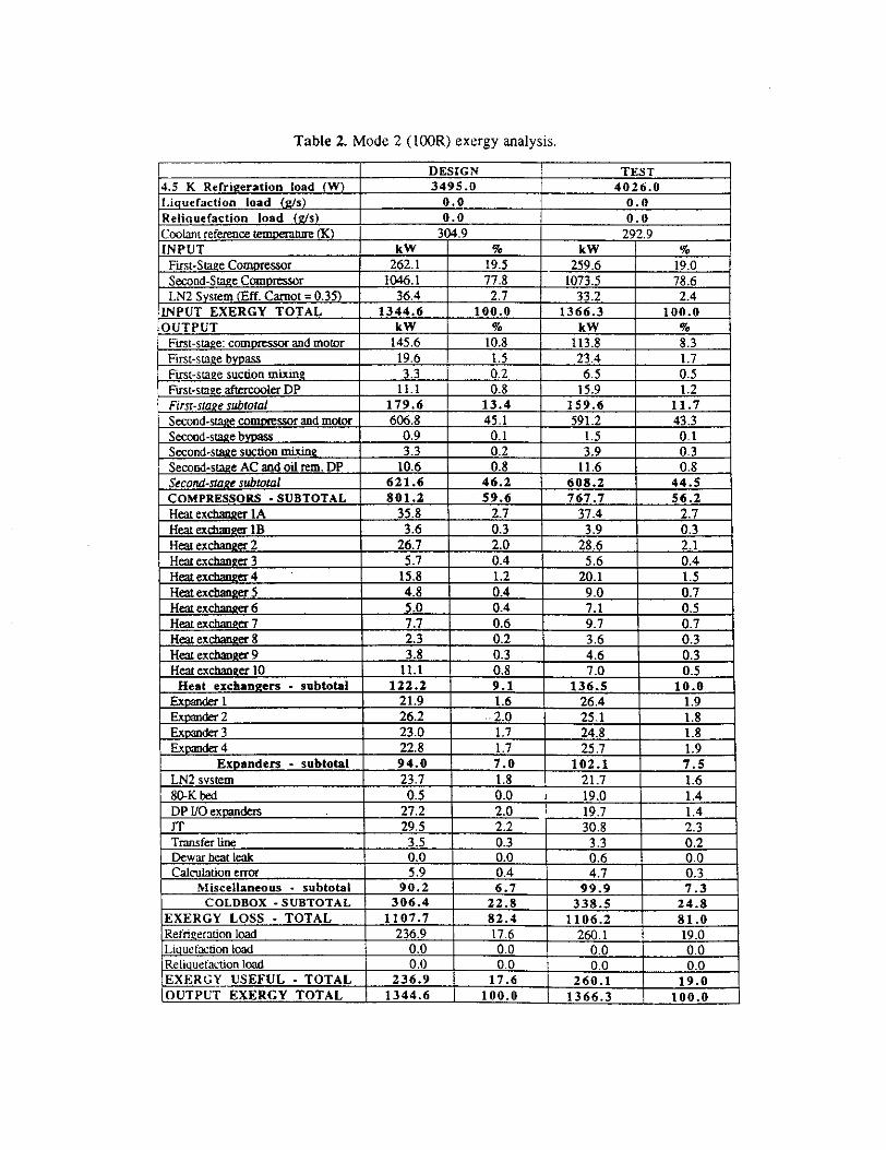
Table 2. Mode 2 100Rexergyanalysis.
P DESIGN TEST4.5 K Refrigeration load W 3495S 4026.0
Liquefaction load g/s OO 0.0Religuefaction load g/s 0.0 0.0CoolantrefezenceemperanreK 304.9 292.9INPUT kW % kW %
First-StageCompressor 262.1 19.5 259.6 19.0Second-Stage ComDressor 1046.1 77.8 1073.5 78.6LN2 System Eft Carnot = 0.35 36.4 2.7 33.2 2.4
INPUT EXERGY TOTAL 1344.6 100S 1366.3 100.0OUTPUT kW % kW %
First-stage:compressorand motor 145.6 10.8 113.8 8.3First-swge bypass 19.6 1.5 23.4 1.7First-stage suction mum 3.3 0.2 6.5 0.5Firsc-srageaftercoolerDP 11.1 0.8 fl.9 1.2First-stage subtotal 179.6 13.4 159.6 11.7Second-staecomixtssorandmotorSecond-swgebypa
606.8 45.1 591.2 43.30.9 0.1 1.5 0.1
Second-sta2esuction mixing 3.3 0.2 3.9 0.3Second-stageACandoilrem.DP 10.6 0.8 11.6 0.8Second-stage subtotal 621.6 46.2 6082 44.5COMPRESSORS -SUBTOTAL 801.2 59.6 767.7 562Heatexchan2er1A 35.8 2.7 37.4 2.7HeaiexthangerlB 3.6 0.3 3.9 0.3Htexchanger2 26.7 2.0 28.6 2.1Heaxexchanger3 5.7 0.4 5.6 0.4Heazexchanger4 . 15.8 1.2 20.1 1.5Heatexcbanger5 4.8 04 9.0 f17Htexchane6 5.0 0.4 7.1 0.5Heatexcbangcr7 7.7 0.6 9.7 0.7Htexcbang8 2.3 0.2 3.6 0.3He3iexcbaaRer9 18 0.3 4.6 0.3Heatexchaner1O 11.1 0.8 7.0 03Heat exchangers - subtotal 122.2 9.1 136.5 10.0
Exçender1 2L9 1.6 26.4 1.9Expander2 26.2 10 25.1 1.8Exnder3 23.0 1.7 24.8 1.8Expider4 22.8 1.7 25.7 1.9
Expanders - subtotal 94.0 7.0 102.1 7.5LN2 system 23.7 1.8 21.7 i.680-K bed 0.5 0.0 19.0 1.4DPliOexpandem . 27.2 2.0 19.7 1.4iT 29.5 2.2 30.8 2.3Tnnser line 15 0.3 3.3 0.2Dewarheatleak 0.0 0.0 0.6 0.0Calculationerror 5.9 0.4 4.7 0.3
Miscellaneous - subtotal 90.2 6.7 99S 7.3COLDBOX SUBTOTAL 306.4 22.8 338.5 248
EXERGY LOSS - TOTAL 1107.7 82.4 i106.2 SLORefngeraUonload 236.9 17.6 260.1 19.0Liguefa.donload 0.0 0.0 0.0 0.0ReliguetacUon load 0.0 0.0 0.0 0.0EXERGY USEFUL - TOTAL 236.9 17.6 260.1 19J1OUTPUT EXERGY TOTAL 1344.6 I 100.0 1366.3 100.0

Table 3. Mode 3 IOOL exergyanalysis.
DESIGN TEST4.5 K Refrigeration load W 0.0 0.0Liquefaction load gls 37.0 34.3Religuetaction load g/s 0.0 6.85Coolant referencetemperalweK 306.6 296.4INPUT kW % kW %
First-StageCompressor 328.1 18.9 262.0 16.6Second-SraeCompressor 1159.5 66.8 1108.1 70.0
LN2 Sysiem EEL Carnot 0.35 247.7 14.3 212.3 13.4INPUT EXERGY TOTAL 1735.3 100.0 1582.4 100.0OUTPUT kW cc kW %
First-stage:compressorandmotor 171.1 9.9 115.3 7.3First-sugebypass 39.8 2.3 50.1 3.2First-stagesuchonmixing 5.6 0.3 8.9 0.6First-stageaftercoolerDP 7.8 0.5 10.8 0.7Fins-stage subtotal 224.3 12.9 185.1 11.7Second-stagecomptessorandmowr 636.8 36.7 605.3 38.3Second-stagebypass 53.6 3.1 56.4 3.6Second-stagesuctionmixing 4.2 0.2 43 0.3Second-stageACandoilrem.DP 10.8 0.6 11.7 0.7Second-stagesubtotal 705.3 40.6 677.8 42SCOMPRESSORS-SUBTOTAL 929.7 53.6 862.9 54.5Heatexchanger1A 61.0 3.5 47.3 3.0HeaLexchangerlB 9.9 0.6 8.4 0.5Heatexcbanger2 19.3 1.1 15.7 1.0Heatexcbangcr3 4.1 0.2 3.8 0.2Heaiexcbanzer4 22.1 1.3 17.6 1.1
f{eaiexcbanger5 . 7.3 0.4 6.3 0.4Heatexchanger6 0.4 0.0 0.3 0.0Heaxexchan&erl 0.6 0.0 2.4 0.2
Heatexchanger8 7.4 0.4 7.1 0.4Heaxexchanger9 5.3 0.3 5.0 0.3HeatexchangerlO 21.9 1.3 22.7 1.4
Heat exchangers - subtotal 159.5 9.2 136.7 8.6Expander! 28.5 1.6 26.6 1.7Exnd2 37.4 2.2 31.5 2.0Expandet3 49.6 2.9 27.5 1.7Exnder4 35.2 2.0 33.2 2.1
Expanders - subtotal 150.6 8.7 118.8 7.5LN2 system 161.0 9.3 138.5 8.880-K bed 0.6 0.0 14.0 0.9DPllOexnnden 0.1 0.0 3.5 0.2iT 62.3 3.6 57.1 3.6Transfer line 3.5 0.2 3.4 0.2Dewarbeatleak 0.0 0.0 0.7 0.0Calculationeu 12.6 0.7 10.9 0.7
Misceflaneous - subtotal 240.1 i3.8 228.1 14.4COLDBOX -SUBTOTAL 550.2 31.7 483.6 30.6
ENERGY LOSS - TOTAL 1479.8 85.3 1346.5 85.1RefrigerationLoad 0.0 0.0 0.0 0.0LiquefactionLoad 255.4 14.7 227.0 14.3ReliguefactionLoad 0.0 0.0 8.9 0.6
EXERGY USEFUL TOTAL 255.4 14.7 235.9 14.9OUTPUT EXERGY TOTAL 1735.3 tOO.O 1582.4 100.0

DISCUSSION AND CONCLUSIONS
The refrigeration systemwas designedto be 50% refrigeratorand 50% liquefier andshould operate over a wide rangeof [cad conditions from 100% refrigeration to 100%liquefaction. The processand exergy analysesare useful tools for comparing the systembehaviorandperformanceat designandoff-designconditions.
The detailedexergy analysespresentedin Tables 1-3 and in Figure 6 show that themiscellaneouslossesand compressorbypassflow losses are a smaller fraction in therefrigerationmodethanin the liquefaction mode.In the liquefaction modenitrogenprecoolingdominatesthe miscellaneouslosses.Somecapacitycan be gained by operatingthe secondStageat a lower suctionpressure,therebyreducingthe bypassflow losses.During the testsconductedsubsequently,the systemwas operatedwith a low setpoint 22 bar for thesecond-stagecompressorsuction.Dependingon the mode, this minimized or eliminatedthesecond-stage bypass flow. The system behaviorwas very stable over a wide range of loadlevels, for all types of load-refrigeration,liquefaction,and mixed. The system pressurelevels adjusted automatically to match the load and thus minimized the input power.Controlledmeasurementswill be madein the future with this self-adjustingcontrol systeminplace, to find the systemmaximum capacity and efficiency. Operatingthe system in somemodesat a higher-than-designsecond-stagepressureratio and dischargepressureresultedinhigher capacities;however,thisresultedin reducedisothermalefficiencies.
Exergyanalysis is a very strong tool for explaininghow input energyis used by theindividual componentsand by the load. Energyoptimizationinvolves minimization ofinputpowerfor a requiredoutputpower,and the norma’questionraisedis: What is the economicoptimum for the componentsin the system?The processindustryusesa constantfor the ratioof monetaryvalue per unit of input powere.g.,$I000/kW. This constantis difficult toapply to the individual components.The exergy lossanalysiscan readily be applied for theeconomicoptimizationof eachcomponentandits effect on the total system.As anexample,the first-stageaftercoolerpressuredrop - 0.3 bar usesapproximatelythe sameamountofenergyasthe combinedpressuredropsacrossthe second-stageaftercoolerand the oil removalsystem-1 bar.This is becausethe sum of the productsof the massflow and the dp/p foreachof theselatteritemsis approximatelyequalto thatofthe former.
60
S‘I0C
0M 20
101st
stage
50
40
302nd
Stag.
C rto
Camp.
C
C FCold b axMode 2
‘a ,jnLoad
I-Camp.
C -
aCotdboxMode 1
C00 uO I-
Load
C, 0
Camp.
C C rVC I-
Coldbox LoadMode 3
Figure 6. Summary of the exergy analysis.

To enhancethe systemeffIciency, improvementscould be madeto the second-stagecompressionprocesseither by designing the systemwith reducedpressureratio for thesecondstage the increasedcompressorefficiency would more than compensatefor theincreasedcoldbox lossesor by usinga different type of compressor.In summary,the exergy
analysiscomparisonof the manufacturer’sdesignwith the actual test for the three modes ofoperationprovidesa clear insight into the componentandsystemlossesandbehavior.
REFERENCES
I. U. WagnerandW. Keyer, "Processdesign featwesof theSSC MTL ciyogenicsystem,’ inSupercolilder3: Proceedingsofthe3rd InternationalSymposiumon theSuperCollider, Atlanta.GA. March1991.New York: Plenum Press, 1992.
2. T. Kobel and R. Than, "Initial operatiocandperfonnancetestresultsof the ASST cryogenicsystem,"tobe publishedin Siapercoll14cr 5: Proceedingsofthe 5th InternationalSymposiumon theSuperCollider, San Francisco,CA, May 1993, New York: Plenum Press.
3. C. Trepp,"Refrigeradocsystemsfor the temperatures below 25K with wrboexpanders.’in AdvancesinCryogenicEngineering,Vol. 7, New Yort PlenumPress.1962, p. 251.
4. B. Ziegler, "Secondlaw analysisof the helium refrigeratorsfor the HERA proton magnetring." inAdvances in CryogenicEngineering,Vol. 31, New York: PlenumPress, 1985, p. 693.

COMPARISON OF ASST-A HELIUM P LIONSYSTEM PERFORMANI
DESIGN VS. ACTUAL TEST AT 50% OF coMpRF:SS0R FLOW CONDITIONS
T.V.V.R. ApparaoandV. GanniCryogenicsDepartment.AcceleratorSystemsDivision
SSCLaboratory,Dallas,TX 75237
The ASST-A refrigerationsystemhastwo first stageand two secondstagecompressors.Parametrictestson thecompressorsand the total refrigerationsystemwere conductedto verify the performanceandcomparethese results with the manufacturer’s design for this refrigeration system. A summaiy of the initialperformancetest data is given in reference[I]. The refrigcraticm system is designed to operate in sevenmodes. However,the main modes ofoperationare: Mode 1 50% refrigeration - 50% Liquefaction.Mode 2100% RefrigerationandMode 3100%Liquefaction.Under normal conditionsof operationall the fourcompressorsare running. The resultsof the processanalysesandexergyanalysesfor the manufacturersdesignand actual test datafor CaseI conditions when all the four compressors amoperatingare discussedin reference[2]. The process flow diagram. the mapping of the compressors, the description of the cold box system andtue theory behind the process andexergy analysesare also given in reference [21. This report presentstheprocessandexergy analyses for the thiec modesof operadonfor Case2 conditionswhenonly one first stageandone second stage compressorsare operated.
Figure I comparesthe manufacturer’sdesign vs. actualreducedtestdata of thepmcesson a T-S diagramfor Mode 1 operation in this mode according to the manufacturers design the 4 K refrigerationcapacity is765 Watts in addition to the plant liquefaction load of 7.65 g/salso at 4 K. The system is designed to operatewith all the four expandersoperating.However,in the actual testas shown on Ehe T-S diagramfigure 1 forthe test data, the system operatedwith the expander3 shutoff. The plant produced 7.4 g/s of liquid at 4 K andthe 4 K refrigeration load was 795 watts, table I compares the total exergy distribution or themanufacturer’sdesign andtest conditions.
Thecoinpazisonfor Mode 2 100% refñgfentionoperationof themanufacturersdesign and reduced testdata for the process is shown on a T-S diagram in figure 2. The plant was designedto operatein this modewith a capacity of 1370 watts of refrigeration at 4 K. During the test, the applied toad on the plant wasashigh as 1450 watts. Theprobable reasons far the higher capacityof the plant are dueto theselectionof largercapacity compressors anda lower suction temperatureof the first stage compressor. The distribution ofexergyiii the compressor system, the cold box and the dewar for the manufacturer’sdesign and the actual test aregiven in Table 2,
The xesultsfor Mode 3 operation100% liquefaciion for the manufacture?sdesign and the reduced testdata for the process are shownin figure 3. Theplant wasdesignedto liquefy 15.6 g/s with onefirst andonesecond stage compressors operating,During the tests conducted to verify the plant capacityin this mode ofoperation,the liquefaction rate was as high as 18.0 g/s. The resultsof the exergyanalysis for this modeofoperationare shown in Table 3. Figure 4 summarizesthe exergy distribution of all the three modesofoperations for Case 2 conditions.
Discussion ot results
TheASST-A refrigerationsystemundernormal conditionsof operationrequirestwo first stageandtwosecondstagecompressors.Theplant is designedto operateat maximumefficiency when operatedin mode Iunder Case I conditions. The efficiency of this refrigerationsystem for all other modesandcasesof operationis lower. As shown in reference 21 the system efficiency for Mode I Case I designoperation is 18.6%. ForMode I andCase2 operationhe system efficiency as given in Table 1 is 14.3% for the manufacturer’sdesignand 14.8% or the testdata Comparisonof the ezergylossesfor Case I with the exergy losses for Case 2 forall the threemodes of operationshows thata largerpercentageof the losses are in the cold box for Case2operation. The larger percentage of the exergy losses for Case 2 operationare mainly due to the higherinefficiencies in the heat exchangers. The exergy losses in theheatexchangers in Mode 1 andCase2 operationfor the manufacturer’sdesignandtestconditionsas given in Table 1 are 13.3%. Whereas for Mode 1 andCaseI operation the exergy losses in the heat exchangersas given in Table I of reference[2] for the manufacturefsdesign and test data are 9.0%. Theheat exchangers are designed for massflow rates, heatloads andpinchesasrequiredfor CaseI conditions. However, the mass flow ratesandheat loads in Case 2 are much lower. Hencethe values of LMTD especiallyin the lower end of the cold box are higher resulting in higher exergy losses.The percentage of exergy losses in the expanders in Case 1 and Case 2 operationareaboutthe same.
1. T. Kobel andB.. Than, Initial operation andperformancetest msults of the ASST cryogenic system,to be published in "Supercoflider 5: Proceedings of the 5th InternationalSymposium on the Super Collider,SanFrancisco,CA. May 1993." New York: Plenum Press.
2. V. Ganni and T.V.V.R. Apparao,Design Verification andAcceptanceTests of the ASST-A HeliumRefrigerationSystem. Presented at the CEC-ICEC Conference, Albequerque. New Mexico. July 12- 16.1993.

3032 IC145 g/s
S.
K.. -
K..
a’,Design Test
Figure 1: Mode 1 $OL-SOR Processanalysis
1 first stageand 1 secondstagecompressorsoperating
s/s

Table I: Mode I 50L-SORLergy anaiysis for 50% compressor flow conditions.
DESIGN TEST4.5 K Refrigeration load W 765.0 795.0Liquefaction load gls 7.65 7.4Reliquefaction load gfs 0.0 1. $Coolant referencetemperatureK 305.8 296.95INPUT kW % kW %
First-Stage Compressor 192.4 26.3 146.3 20.9Second-Stage Compressor 475.5 65.0 502.8 71.9LN2 SysLem Elf. Carnot = 0.35 63.8 &.7 5Q.j 7.2
INPUT EXERGY TOTAL 731.7 100.0 699.2 100.0OUTPUT kW % kW %
First-stage:compressor& motor 99.5 13.6 62.4 8.9First-stagebypass 3.8 0.5 21.2 3.0First-stagesuction mixing 2.1 0.3 2.2 0.3First-stageaftercoolerDP 3.0 0.4 4.6 0.7First-stage subtotal 108.6 14.8 90.4 12.9Second-stage compressor & motor 255.8 35.0 245.1 35.1Second-stage bypass 5.3 0.7 1.6 0.2Second-stage suction mixing 2.5 0.3 1.4 0.2Second-stageAC & oil rem. 1* 109 1.5 10.6 1.5Second-stage subtotal 274.5 37.5 258.8 37.0
C0MPRESs0Rs-sualorAL 383.1 52.4 349.1 49.9HeatexchangerlA 28.9 4.0 19.0 2.7Heat exchanger lB 3.4 0.5 1.0 0.1Heat exchanger2 20.1 2.8 21.3 3.1.Heatexchanger3 2.9 0.4 3.4 0.5Heatexchanger4 . 11.8 1.6 12.0 1.7
Heatcxchanger5 1.9 0.3 3.1 0.4Heatexchanger6 0.8 0.1 0.8 0.1Heat exchanger7 1.9 0.3 2.4 0.3Heat exchanger8 7.2 1.0 17.5 2.5Heat exchanger 9 3.4 0.5 0.0 0.0
HeatexchangerlO 14.9 2.0 12.3 1.8Heat exchangers. - subtotaL 97.3 L3.3 92.8 13.3
Expander! 15.2 2.1 20.1 2.9Expander2 17.9 2.4 14.2 2.0Expander3 10.1 1.4 0.0 0.0Expander 4 17.6 2.4 20.9 3.0
Expanders - subtotal 60.8 8.3 55.2 7.9
LN2 system 41.7 5.7 32.6 4.7
SOKbed 0.5 0.1 13.0 1.9DPI/Oexpanders 5.7 0.8 19.3 2.8iT 31.8 4.3 22.3 3.2Transfer line 3.5 0.5 3.4 0.5Dewarheatleaic 0.0 0.0 0.7 0.1Calculation error 2.6 0.4 7.2 1.0
Miscellaneous - subtotal 8S.8 I 1.7 98.6 14.1C0LDB0X-suuTor.u, 244.0 33.3 246.6 35.3
EXERGY LOSS TOTAL 627.0 85.7 595.7 85.2Refrigerationload 52.0 7.1 52.5 7.5
Liquefactionload 52.6 1.2 49.1 7.0
Reliquefaction load 0.0 0.0 1.9 0.3EXERGY USEFUL -TOTAL 104.6 14.3 103.5 14,8OUTPUT EXERGY TOTAL 731.1 100.0 699.2 100.0

302.0 K 1.17 b.r
flgun 2 :Mode 2 ProcessanaIyss1 first stageand1 secondstagecompressorsoperating
g/S
K
K
A 100R Design B 100RTest

Table 2: Mode 2 IOOR Exergy analysis for 50% compressor flow ionuIcuorh,.
DESIGN TEST4.5 K Refrigeration load W 1370.0 1450.0
Liquefaction load g/s 0.0 0.0Reliquefaction load g/s 0 . 0 0 .0
Coolant reference temperature K 304.9 294.9
INPUT kW % ?CW %First-StageCompressor 193.6 27.8 151.1 22.1
Second-Stage Compressor 476.4 68.5 513.5 75.3LN2 SystemElf. Carnot= 035 25.6 3.7 17.6 2.6
INPUT EXERGY TOTAL 695.6 100.0 682.2 100.0OUTPUT kW % tcW %
First-stage: compressortc motor 100.2 14.4 64.6 9.5
First-stage bypass 4.1 0.6 t8.6 2.7First-stage suction mixing 1.7 0.2 0.7 0.1
Fixst-stage aftercooler op 3.0 0.4 4.8 0.7
First-stage subtotaL 109.0 15.7 88.8 13.0Second-stagecompressor& motor 256.8 36.9 249.7 36.6
Second-stage bypass 6.3 0.9 20.4 3.0Second-stagesuction mixing 2.5 0.4 1.6 0.2Second-stage AC & oil rem. DP 11.0 1.6 10.7 1.6Second-stage subtotal 276.7 39.8 282.4 41.4
COMPRESSORS-SUBTOTAL. 385.1 55.4 371.2 54.4HeatexchangerlA 28.1 4.0 14.9 21HeatexchangerlB 2.7 0.4 0.4 0.1Heat exchanger 2 25.8 3.7 20.7 3.0Heat exchanger 3 2.5 0.4 2.9 0.4Heat exchanger 4 11.9 1.7 8.2 1.2Heat exchanger5 1.7 0.3 2.0 0.3Heat exchanger 6 0.8 0.1 0.9 0.1Heatexchanger7 1.9 0.3 2.5 0.4Heatexchanger8 10.1 1.5 25.0 3.7
Heat exchanger9 3.2 0.5 0.0 0.0Heat exchanger 10 14.1 2.0 10.3 1.5
Heat exchangers - subtotal 103.0 14.8 87.9 12.9Expander1 17.7 2.5 20.6 3.0Expander2 16.0 2.3 9.0 1.3Expander 3 8.5 1.2 0.0 0.0Expander 4 15.8 2.3 20.9 3A
Expanders - subtotal 58.0 8.3 50.6 7.4LN2 system 16.7 24 11.4 1.7SOKbed 0.5 0.1 12.6 1.8DPI/Oexpanders 11.3 1.6 24.9 37iT 23.8 3.4 19.7 2.9Transfer line 3.5 0.5 3.3 0.5
Dewarheatleak 0.0 0.0 0.6 0.1Calculation error 0.2 0.0 6.0 03
Miscellaneous - subtotal 56.0 8.0 78.6 u.SCoLDnox-sUgtoTAI. 217.0 31.2 211.1 31.8
EXERGY LOSS - TOTAL 602.7 86.6 588.3 86.2Refrigeration load 92.9 13.4 93.9 13.8Liquefaction load 0.0 0.0 0.0 0.0Reliquefaction toad 0.0 0.0 0.0 0.0
EXERGY USEFUL -TOTAL 92.9 13.4 93.9 13.8OUTPUT EXERGY TOTAL 695.6 100.0 682.2 100.0

Figure 3 Mode 3 Processanalysis1 first stageand 1 secondstagecompressorsoperating
15.6 gfs
bit.1 K
1&Og/s
K
ICK..
IC.
A 100L Design B 100L Test
g/s

Table 3: Mode 3 tOOL Exergy analysis for 50% compressor flow conditions.
DESIGN TEST4.5 K Refrigeration load W 0.0 0.0
Liquefaction load gls I 5.6 18.0
Reliquefaction load gls 0.0 3.6
Coolant referencetemperature K 306.6 302.8
INPUT kW % kW %
First-Stage Compressor 187.5 24.5 166.9 20.5Second-Stage Compressor 474.2 62.0 526.6 64.7
LN2 System Elf. Carnot = 0.35 102.9 13.5 120.2 14.8
INPUT EXERGY TOTAL 764.6 100.0 813.7 100.0
OUTPUT kW % kW Ye
First-stage: compressor & motor 97.0 12.7 71.1 8.7
Fixst.stagebypass 3.2 0.4 2S.9 3.5First-stage suction mixing 2.6 0.3 0.7 0.1
Eirst-stage aitercooler DP 3.2 0.4 3.9 0,5
First-stagesubiolal 106.0 13.9 104.7 12.9
Second-stagecompressor& motor 254.7 33.3 244.6 30,1
Second-stagebypass 6.5 0.8 24.8 3,0Second-stagesuction mixing 2.4 0.3 1.6 0.2
Second-stage AC & oil rein. DP 10.5 1.4 12.2 1.5
Second-stagesubtotal 274.1 35.8 283.2 34.8
COMPRESSORS -SUBTOTAL 380.0 49.7 387.9 47.7
HeatexchangerlA 30.6 4.0 2L5 3.3HeatexchangerlB 4.3 0.6 2.7 0.3
Heatexchanger2 13.6 1.8 18.5 2.3
Heatexchanger3 2.6 0.3 3.2 0.4
Heatexchanger 4 , 10.0 1.3 13.2 1.6HeatexchangerS 2.0 0.3 2.9 0.4
Heatexchaziger6 1.2 0.2 0.7 0.1
Fleatexchanger7 2.3 0.3 2.9 0.4
HeatexehangerS 5.9 0.8 12.5 1.5
Heatexchanger9 3.9 0.5 0.0 0.0
Heat exchanger10 17.9 2.3 12.1 1.5
Heat exchangers - subtotal 94.3 12.3 9S.3 11.7
Expander 1 14.2 1.9 22.2 2.7
Expander 2 16.1 2.1 17.3 2.1Expander3 14.7 1.9 0.0 0.0Expander4 17.3 2.3 25.0 3.1
Expanders - subtotal 62.3 8.2 64.5 7,9LN2 system 67.2 8.8 78.1 9.68OKbed 0.4 0.1 t5.2 i.9DPI/Oexpanders 0.0 0.0 1.8 0.2
JT 43.9 5.7 30.1 3.7
Transfer line 3.5 0.5 3.5 0.4
Dewarheatleak 0.0 0.0 0.7 0.1
Calcutation error 5.1 0.7 9.8 1.2MsceIIaneous - subtotal 120.2 15.7 139.2 17.1
COLDROX-SUBTOTAI. 216.9 3L2 299.0 36.7EXERGY LOSS - TOTAL 656.9 8S.9 686.9 84.4
Refrigeration Load 0.0 0.0 0.0 0.0
Liquclaction Load 107.7 14.1 122.1 15.0Reliquefaction Load 0.0 0.0 4.8 0.6
EXERGY USEFUL -TOTAL 107.7 14.1 126.9 15.6OUTPUT EXERGY TOTAL 764.6 100.0 813.7 100.0

1 first stage and 1 second staqe compressorsoperating
Comp. Caldbox LoadMode 2
Camp. Coldbox LoadMode 1
Camp. Coldbox LoadMode 3
60 -
Sc
-et. 40CCI‘UUI3O>1
0w
Ui
10
C- = -
to V to0 0 EQ
= C0
0 - Q5
ij o oE- OF’
Figure4: Summaryof Exergy Analysis