MagnaloyProductsCatalog · PDF fileRadial Lug Design... is logical and efficient. The most...
18
Magnaloy Products Catalog A Division of Douville Johnston Corporation Fax: 989 354-4190 http://www.magnaloy.com magnaloy coupling company 501 Commerce Drive Alpena, MI 49707 989 356-2186 Catalog No. PC0910 © 2010 Magnaloy Coupling Co. MGI 0910 - 3M QUICK INDEX: Full Product Index ......... i Flexible Drive Couplings Premium Line PM 90 Coupling Pump/Motor Mounts General Information Horizontal Mounts Vertical Mounts Engine Mounts Welded Steel Mounts Bar Manifolds General Information In-Line Bar Manifolds IntegratedCircuit Manifolds Subplates Cover Plates Valve Adaptors Manifold Accessories Header Bar Manifolds Junction Bar Manifolds Reservoirs General Information Reservoirs End Covers Accessories Filler Breathers Reservoir Flanges Channel Mounted Cushion Clamps Modular Cushion Clamps Suction Strainers Tank Diffusers Spin-On Filters Tank Top Filters Pressure Gauges Liquid Level Gauges SAE Couplings Motor Dampening Bars Motor Base Plates Gauge Isolators Pressure Switch Modular O’Ring Kit Rod Alignment Couplers M Series R Series Reference Section C 1 2 3 4 5 6 R North America’s Favorite Source for Fluid Power Accessories
Transcript of MagnaloyProductsCatalog · PDF fileRadial Lug Design... is logical and efficient. The most...

Magnaloy Products Catalog
A Division of Douville Johnston Corporation Fax: 989 354-4190 http://www.magnaloy.com
magnaloy coupling company 501 Commerce Drive Alpena, MI 49707 989 356-2186
Catalog No. PC0910 © 2010 Magnaloy Coupling Co. MGI 0910 - 3M
QUICK INDEX:Full Product Index . . . . . . . . . i
Flexible Drive CouplingsPremium LinePM 90 Coupling
Pump/Motor MountsGeneral InformationHorizontal MountsVertical MountsEngine MountsWelded Steel Mounts
Bar ManifoldsGeneral InformationIn-Line Bar ManifoldsIntegratedCircuit ManifoldsSubplatesCover PlatesValve AdaptorsManifold AccessoriesHeader Bar ManifoldsJunction Bar Manifolds
ReservoirsGeneral InformationReservoirsEnd Covers
AccessoriesFiller BreathersReservoir FlangesChannel Mounted Cushion ClampsModular Cushion ClampsSuction StrainersTank DiffusersSpin-On FiltersTank Top FiltersPressure GaugesLiquid Level GaugesSAE CouplingsMotor Dampening BarsMotor Base PlatesGauge IsolatorsPressure SwitchModular O’Ring Kit
Rod Alignment CouplersM SeriesR Series
Reference Section
C
1
2
3
4
5
6
R
North America’s Favorite Source forFluid Power Accessories

Product Index
magnaloy coupling company 501 Commerce Drive Alpena, MI 49707 989 356-2186A Division of Douville Johnston Corporation Fax: 989 354-4190 http://www.magnaloy.com
ii
Flexible Drive Couplings - SECTION 1Premium Flexible Drive Couplings . . . . . . . . . . . . . . . . . . . . . . . . . . . . . . . . . . 3PM90 Flexible Drive Coupling . . . . . . . . . . . . . . . . . . . . . . . . . . . . . . . . . . . . . . 13
Pump/Motor Mounts - SECTION 2General Information . . . . . . . . . . . . . . . . . . . . . . . . . . . . . . . . . . . . . . . 19Horizontal Pump/Motor Mounts (NEMA Frame Motors). . . . . . . . . . . . . . . . . . . . . . . . . . . . . . . . 20Horizontal Pump/Motor Mounts (IEC Metric Frame Motors) . . . . . . . . . . . . . . . . . . . . . . . . . . . . . . . 23 Vertical Pump/Motor Mounts . . . . . . . . . . . . . . . . . . . . . . . . . . . . . . . . . 27Pump/Engine Mounts . . . . . . . . . . . . . . . . . . . . . . . . . . . . . . . . . . . . . . . 30Horizontal Welded Steel Pump/Motor Mounts . . . . . . . . . . . . . . . . . . . . . . . . . . . 33Vertical Welded Steel Pump/Motor Mounts . . . . . . . . . . . . . . . . . . . . . . . . . . . 36Welded Steel Pump/Engine Mounts . . . . . . . . . . . . . . . . . . . . . . . . . . . . . . . 39Pump/Motor Mount Dampening Ring . . . . . . . . . . . . . . . . . . . . . . . . . . . . . . 42
Hydraulic Bar Manifolds - SECTION 3General Information . . . . . . . . . . . . . . . . . . . . . . . . . . . . . . . . . . . . . . . 46In-line Bar Manifolds . . . . . . . . . . . . . . . . . . . . . . . . . . . . . . . . . . . . . . 47Integrated Circuit Manifolds . . . . . . . . . . . . . . . . . . . . . . . . . . . . . . . . . . 72Subplates . . . . . . . . . . . . . . . . . . . . . . . . . . . . . . . . . . . . . . . . . . 76Cover Plates . . . . . . . . . . . . . . . . . . . . . . . . . . . . . . . . . . . . . . . . . 85Valve Adaptors . . . . . . . . . . . . . . . . . . . . . . . . . . . . . . . . . . . . . . 92Manifold Accessories . . . . . . . . . . . . . . . . . . . . . . . . . . . . . . . . . . 97
Orifice Plate . . . . . . . . . . . . . . . . . . . . . . . . . . . . . . . . . . . . . 100Tapping Plate . . . . . . . . . . . . . . . . . . . . . . . . . . . . . . . . . . . . 102
Header Bar Manifolds . . . . . . . . . . . . . . . . . . . . . . . . . . . . . . . . . . 106Junction Bar Manifolds . . . . . . . . . . . . . . . . . . . . . . . . . . . . . . . . . 112
Reservoirs - SECTION 4General Information . . . . . . . . . . . . . . . . . . . . . . . . . . . . . . . . . . . 116Vertical Reservoirs . . . . . . . . . . . . . . . . . . . . . . . . . . . . . . . . . . . . 117Dual Vertical Reservoirs . . . . . . . . . . . . . . . . . . . . . . . . . . . . . . . . 122JIC Reservoirs . . . . . . . . . . . . . . . . . . . . . . . . . . . . . . . . . . . . . . 124L Shaped Reservoirs . . . . . . . . . . . . . . . . . . . . . . . . . . . . . . . . . . . 126T Shaped Reservoirs . . . . . . . . . . . . . . . . . . . . . . . . . . . . . . . . . . . 130Horizontal Reservoirs . . . . . . . . . . . . . . . . . . . . . . . . . . . . . . . . . . . 132Drip Pans . . . . . . . . . . . . . . . . . . . . . . . . . . . . . . . . . . . . . . . 134Stacking Modules . . . . . . . . . . . . . . . . . . . . . . . . . . . . . . . . . . . . 135End Covers . . . . . . . . . . . . . . . . . . . . . . . . . . . . . . . . . . . . . . . 136
Reservoir Accessories - SECTION 5Filler Breathers . . . . . . . . . . . . . . . . . . . . . . . . . . . . . . . . . . . . . . 139Reservoir Flanges . . . . . . . . . . . . . . . . . . . . . . . . . . . . . . . . . . . . . 143SAE Full and Half Couplings . . . . . . . . . . . . . . . . . . . . . . . . . . . . . . . . 146Channel Mounted Cushion Clamps . . . . . . . . . . . . . . . . . . . . . . . . . . . . . 147Modular-Stackable Cushion Clamps . . . . . . . . . . . . . . . . . . . . . . . . . . . . . 151Suction Strainers . . . . . . . . . . . . . . . . . . . . . . . . . . . . . . . . . . . . . . 157Tank Diffusers . . . . . . . . . . . . . . . . . . . . . . . . . . . . . . . . . . . . . . . 159Spin-On Filters . . . . . . . . . . . . . . . . . . . . . . . . . . . . . . . . . . . . . . . 160Tank Top Filters . . . . . . . . . . . . . . . . . . . . . . . . . . . . . . . . . . . . . 162Pressure Gauges . . . . . . . . . . . . . . . . . . . . . . . . . . . . . . . . . . . . . 168Gauge Isolators . . . . . . . . . . . . . . . . . . . . . . . . . . . . . . . . . . . . . . . 170Pressure Switches . . . . . . . . . . . . . . . . . . . . . . . . . . . . . . . . . . . . . . 171Liquid Level Gauges . . . . . . . . . . . . . . . . . . . . . . . . . . . . . . . . . . . 172Motor Dampening Bars . . . . . . . . . . . . . . . . . . . . . . . . . . . . . . . . . . . . . . 174Motor Base Plates . . . . . . . . . . . . . . . . . . . . . . . . . . . . . . . . . . . . 179Modular O-Ring Kit . . . . . . . . . . . . . . . . . . . . . . . . . . . . . . . . . . . . . 180
Cylinder Rod End Alignment Couplers - SECTION 6M - Series Specifications . . . . . . . . . . . . . . . . . . . . . . . . . . . . . . 182R - Series Specifications . . . . . . . . . . . . . . . . . . . . . . . . . . . . 184
REFERENCE MATERIAL INDEX . . . . . . . . . . . . . . . . . . . . . . . . . . . . . . . . . 188

magnaloy coupling company 501 Commerce Drive Alpena, MI 49707 989 356-2186A Division of Douville Johnston Corporation Fax: 989 354-4190 http://www.magnaloy.com
11
1
Magnaloy Flexible Drive Couplings
NOTE: Due to Magnaloy’s policy of continuous improvement, specificaitons are subject to change without notice. Check with the factory or our Web Site at www.magnaloy.com for the latest information.
SECTION 1
MAGNALOY FLEXIBLE DRIVE COUPLINGS

Magnaloy Coupling Design Features
magnaloy coupling company 501 Commerce Drive Alpena, MI 49707 989 356-2186A Division of Douville Johnston Corporation Fax: 989 354-4190 http://www.magnaloy.com
22
1
Load-Lock Design... is simple and effective. The drive lugconfiguration is tapered from top to base, as are the matinglugs of the opposing coupling hub. Under load, the insert conforms to the tapers, inter-locking the two hubs. This load-lockdesign protects bearings and equipment by eliminating endthrust in both directions.... and it requires only one set-screw ineach hub.
11 Radial Lug Design... is logical and efficient. The most common failure of anelastomeric insert type drive coupling is hysteresis failure of the elastomericelement - breakdown of the elastomer due to cyclical overworking and theassociated heat generation. Magnaloy Coupling’s drive lugs are in a trueradial orientation. Applied forces are evenly distributed in the compressivedirection only, eliminating the heat generating radial component. Truecompressive loading reduces internal heat generation and improves elastomerlife.
Magnaloy Coupling Design...Under loaded conditions, the resultant forces applied on the element segments are evenly distributed in the compressive direction only. This results in no radial forces to multiply the internal heat generation.
Conventional Design A...Under loaded conditions this jaw design results in the applied forces exerting components in the compressive and radial directions. These forceschange direction and magnitude along the jaw arc which greatly increasethe internal movement of the element which causes heat generation.
Conventional Design B...This more conventional straight sided jaw design also exerts componentforces in the compressive and radial directions when under load. The radial component is outward (acting to extrude the element) and changesin magnitude only, as does the compressive component, along the jaw surface. The component forces resulting from this design also causesincreased internal movement in the element.
A note about Set-Screws ...The Premium Line of Magnaloy Couplings comes standard with a single set-screw over the keyway. OptionalDouble Set-Screws are available at either 45o or 90o to the keyway. Double set-screws help improve shaft gripping forces by increasing the hoop-stresses generated from tightening a single set-screw. Double set-screwsat 45o will produce greater forces than double set-screws at 90o. Either are available upon request by specifying ‘DSS45’ or ‘DSS90’ following the hub part number. M30011210DSS45Magnaloy’s Clamp feature is also availble with bored and keyed hubs, specify ‘C’ following the hub part number. M30011210C
Premium Flexible Drive Couplings
magnaloy coupling company 501 Commerce Drive Alpena, MI 49707 989 356-2186A Division of Douville Johnston Corporation Fax: 989 354-4190 http://www.magnaloy.com
33
1
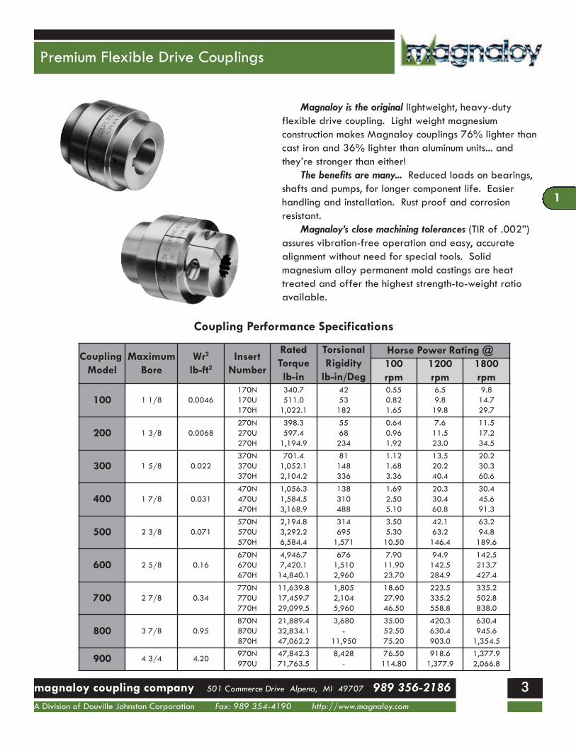
Magnaloy is the original lightweight, heavy-duty flexible drive coupling. Light weight magnesium construction makes Magnaloy couplings 76% lighter thancast iron and 36% lighter than aluminum units... andthey’re stronger than either!
The benefits are many... Reduced loads on bearings,shafts and pumps, for longer component life. Easier handling and installation. Rust proof and corrosion resistant.
Magnaloy’s close machining tolerances (TIR of .002”)assures vibration-free operation and easy, accuratealignment without need for special tools. Solid magnesium alloy permanent mold castings are heattreated and offer the highest strength-to-weight ratioavailable.
CouplingModel
MaximumBore
Wr2
lb-ft2Insert
Number
RatedTorquelb-in
TorsionalRigidity
lb-in/Deg
Horse Power Rating @100rpm
1200rpm
1800rpm
100 1 1/8 0.0046170N170U170H
340.7511.01,022.1
4253182
0.550.821.65
6.59.819.8
9.814.729.7
200 1 3/8 0.0068270N270U270H
398.3597.41,194.9
5568234
0.640.961.92
7.611.523.0
11.517.234.5
300 1 5/8 0.022370N370U370H
701.41,052.12,104.2
81148336
1.121.683.36
13.520.240.4
20.230.360.6
400 1 7/8 0.031470N470U470H
1,056.31,584.53,168.9
138310488
1.692.505.10
20.330.460.8
30.445.691.3
500 2 3/8 0.071570N570U570H
2,194.83,292.26,584.4
3146951,571
3.505.3010.50
42.163.2146.4
63.294.8189.6
600 2 5/8 0.16670N670U670H
4,946.77,420.114,840.1
6761,5102,960
7.9011.9023.70
94.9142.5284.9
142.5213.7427.4
700 2 7/8 0.34770N770U770H
11,639.817,459.729,099.5
1,8052,1045,960
18.6027.9046.50
223.5335.2558.8
335.2502.8838.0
800 3 7/8 0.95870N870U870H
21,889.432,834.147,062.2
3,680-
11,950
35.0052.5075.20
420.3630.4903.0
630.4945.61,354.5
900 4 3/4 4.20970N970U
47,842.371,763.5
8,428-
76.50114.80
918.61,377.9
1,377.92,066.8
Coupling Performance Specifications
1
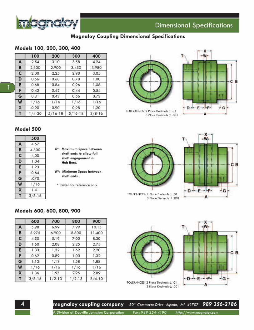
600 700 800 900A 5.98 6.99 7.99 10.15B 5.975 6.900 8.600 11.400C 4.50 5.19 7.00 8.30D 1.60 2.08 2.25 2.75E 1.33 1.32 1.62 2.20F 0.62 0.89 1.00 1.32G 1.13 1.13 1.58 1.88W 1/16 1/16 1/16 1/16X 1.36 1.97 2.25 2.89T 3/8-16 1/2-13 1/2-13 3/4-10
Dimensional Specifications
magnaloy coupling company 501 Commerce Drive Alpena, MI 49707 989 356-2186A Division of Douville Johnston Corporation Fax: 989 354-4190 http://www.magnaloy.com
44
1
Magnaloy Coupling Dimensional Specifications
Models 100, 200, 300, 400
Models 600, 600, 800, 900
Model 500
100 200 300 400A 2.54 3.10 3.58 4.24B 2.600 2.900 3.450 3.980C 2.00 2.25 2.90 3.05D 0.56 0.68 0.78 1.00E 0.68 0.84 0.96 1.06F 0.42 0.42 0.44 0.54G 0.31 0.43 0.56 0.73W 1/16 1/16 1/16 1/16X 0.90 0.90 0.98 1.20T 1/4-20 5/16-18 5/16-18 3/8-16
500A 4.67B 4.800C 4.00D 1.04E 1.23F 0.64G .070W 1/16X 1.41T 3/8-16
X*: Maximum Space betweenshaft ends to allow fullshaft engagement inHub Bore.
W*: Minimum Space betweenshaft ends.
* Given for reference only.
TOLERANCES: 2 Place Decimals ± .013 Place Decimals ± .001
TOLERANCES: 2 Place Decimals ± .013 Place Decimals ± .001
TOLERANCES: 2 Place Decimals ± .013 Place Decimals ± .001
11

Bore & Keyway Combinations
magnaloy coupling company 501 Commerce Drive Alpena, MI 49707 989 356-2186A Division of Douville Johnston Corporation Fax: 989 354-4190 http://www.magnaloy.com
55
1
Standard Bore and Keyway CombinationsMagnaloy “Standard” Bore Key Combinations
Model Bore/KeyCode Code
Model 100200300400500600700800900
Bore KeyM _ _ _ 01203M _ _ _ 01403M _ _ _ 01404M _ _ _ 01604M _ _ _ 01804M _ _ _ 02005M _ _ _ 02006M _ _ _ 02206M _ _ _ 02404M _ _ _ 02406M _ _ _ 02806M _ _ _ 02808M _ _ _ 03008M _ _ _ 10006M _ _ _ 10008M _ _ _ 10408M _ _ _ 10608M _ _ _ 10808M _ _ _ 10810M _ _ _ 11210M _ _ _ 11212M _ _ _ 11412M _ _ _ 11610M _ _ _ 11612M _ _ _ 12012M _ _ _ 12412
3/8 x 3/327/16 x 3/327/16 x 1/8
1/2 x 1/89/16 x 1/8
5/8 x 5/325/8 x 3/16
11/16 x 3/163/4 x 1/83/4 x 3/167/8 x 3/167/8 x 1/4
15/16 x 1/41 x 3/161 x 1/4
1 1/8 x 1/41 3/16 x 1/4
1 1/4 x 1/41 1/4 x 5/161 3/8 x 5/161 3/8 x 3/8
1 7/16 x 3/81 1/2 x 5/161 1/2 x 3/81 5/8 x 3/81 3/4 x 3/8
****************
****************
***
*******************
**
**
***
***
***
*****
***
*******
*****
***
***
***
****
**
***
**
***
Magnaloy “Standard” Bore Key CombinationsModel Bore/KeyCode Code
Model 100200300400500600700800900
Bore KeyM _ _ _ 12414M _ _ _ 12816M _ _ _ 13016M _ _ _ 20016M _ _ _ 20416M _ _ _ 20816M _ _ _ 21220M _ _ _ 21620M _ _ _ 22020M _ _ _ 22420M _ _ _ 22824M _ _ _ 30024M _ _ _ 30824M _ _ _ 31228M _ _ _ 31628M _ _ _ 32028M _ _ _ 32428M _ _ _ 32832M _ _ _ 40032M _ _ _ 40432M _ _ _ 40832M _ _ _ 41232M _ _ _ 41632M _ _ _ 41640M _ _ _ 42040M _ _ _ 42440
1 3/4 x 7/161 7/8 x 1/2
15/16 x 1/22 x 1/2
2 1/8 x 1/22 1/4 x 1/22 3/8 x 5/82 1/2 x 5/82 5/8 x 5/82 3/4 x 5/82 7/8 x 3/4
3 x 3/43 1/4 x 3/43 3/8 x 7/83 1/2 x 7/83 5/8 x 7/83 3/4 x 7/83 7/8 x 1
4 x 14 1/8 x 14 1/4 x 14 3/8 x 14 1/2 x 14 1/2 x 1 1/44 5/8 x 1 1/44 3/4 x 1 1/4
*********
*********
**
********
**
***************
*
***********************
Shaded Area: AGMA semi-standard bore key combinations.
Part Number Usage: Magnaloy Coupling Hub part numbers may be specifiedusing the following format: Start with letter “M” designating Magnaloy, followed by 3 digit Model Code (100, 200, etc.), then the specific 5 digitBore/Key Code.
Example: Model 500 Hub with a 1 /38 bore and 5/16 keyway would bespecified as: M50011210 - No bore hubs are designated as “R” code, ie.M500R.
Over Include Tolerance
--1234
12345
+.0008/+.0003+.0013/+.0005+.0018/+.0008+.0020/+.0010+.0023/+.0010
Bore Tolerances
Model Number 100 200 300 400 500 600 700 800 900
Maximum Bore 1 1/8 1 3/8 1 5/8 1 7/8 2 3/8 2 5/8 2 7/8 3 7/8 4 3/4Complete Coupling Approx. Weight
(Solid Hub)3/4 1 2 3 4 7 12 18 38
Number of Drive Lugs 3 3 3 3 4 6 6 6 6Hub Movement for Insert Removal .74 .74 .75 .98 1.12 1.02 1.50 1.63 2.27Basic Insert Number 170 270 370 470 570 670 770 870 970
Additional Coupling Specifications
1
Splined Couplings
55 magnaloy coupling company 501 Commerce Drive Alpena, MI 49707 989 356-2186A Division of Douville Johnston Corporation Fax: 989 354-4190 http://www.magnaloy.com
66
1
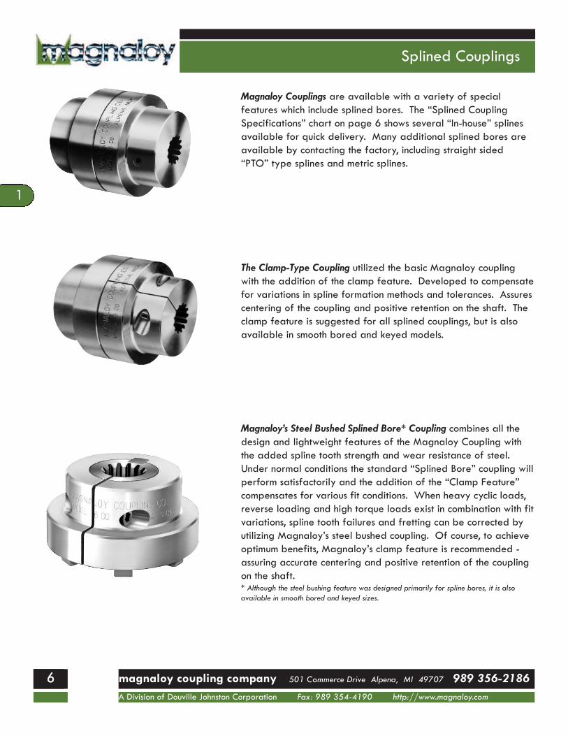
Magnaloy Couplings are available with a variety of special features which include splined bores. The “Splined CouplingSpecifications” chart on page 6 shows several “In-house” splinesavailable for quick delivery. Many additional splined bores areavailable by contacting the factory, including straight sided“PTO” type splines and metric splines.
The Clamp-Type Coupling utilized the basic Magnaloy couplingwith the addition of the clamp feature. Developed to compensatefor variations in spline formation methods and tolerances. Assurescentering of the coupling and positive retention on the shaft. Theclamp feature is suggested for all splined couplings, but is alsoavailable in smooth bored and keyed models.
Magnaloy’s Steel Bushed Splined Bore* Coupling combines all thedesign and lightweight features of the Magnaloy Coupling withthe added spline tooth strength and wear resistance of steel.Under normal conditions the standard “Splined Bore” coupling willperform satisfactorily and the addition of the “Clamp Feature”compensates for various fit conditions. When heavy cyclic loads,reverse loading and high torque loads exist in combination with fitvariations, spline tooth failures and fretting can be corrected byutilizing Magnaloy’s steel bushed coupling. Of course, to achieveoptimum benefits, Magnaloy’s clamp feature is recommended -assuring accurate centering and positive retention of the couplingon the shaft.* Although the steel bushing feature was designed primarily for spline bores, it is alsoavailable in smooth bored and keyed sizes.
11
Splined & Clamp Specifications
66magnaloy coupling company 501 Commerce Drive Alpena, MI 49707 989 356-2186A Division of Douville Johnston Corporation Fax: 989 354-4190 http://www.magnaloy.com
77
1
Spline Size PressureAngle
(Degrees)
SAEDesignation
MajorDiameter(Inches)
Std CouplingAvailable
Model Sizes
Steel Bushed CouplingNumberof Teeth
PitchRatio
SplineCode
BushingDiameter
AvailableModel Sizes
913131415151721232740
16/328/1616/3212/248/1616/3212/2416/3216/3216/3216/32
09161308131614121508151617122116231627164016
300
300
300
300
300
300
300
300
300
300
300
AD, EBCFBBCC
0.6251.7500.8751.2502.0001.0001.5001.3751.5001.7502.562
100 - 900400 - 900100 - 900200 - 900500 - 900100 - 900300 - 900300 - 900300 - 900400 - 900600 - 900
1.2502.6251.5002.2503.5001.7502.2502.2502.2501
2.6252
3.875
200 - 600600 - 900300 - 800500 - 900800 - 900400 - 800500 - 900500 - 900500 - 900600 - 900800 - 900
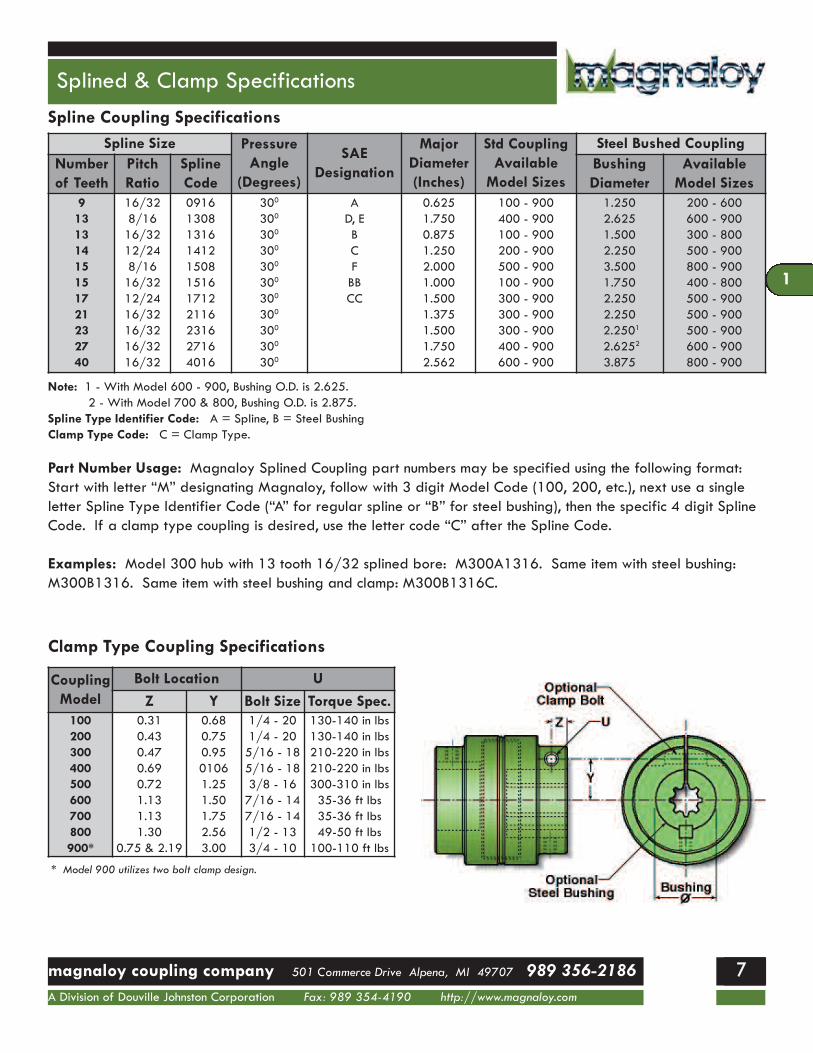
Note: 1 - With Model 600 - 900, Bushing O.D. is 2.625.2 - With Model 700 & 800, Bushing O.D. is 2.875.
Spline Type Identifier Code: A = Spline, B = Steel BushingClamp Type Code: C = Clamp Type.
Spline Coupling Specifications
Part Number Usage: Magnaloy Splined Coupling part numbers may be specified using the following format:Start with letter “M” designating Magnaloy, follow with 3 digit Model Code (100, 200, etc.), next use a singleletter Spline Type Identifier Code (“A” for regular spline or “B” for steel bushing), then the specific 4 digit SplineCode. If a clamp type coupling is desired, use the letter code “C” after the Spline Code.
Examples: Model 300 hub with 13 tooth 16/32 splined bore: M300A1316. Same item with steel bushing:M300B1316. Same item with steel bushing and clamp: M300B1316C.
CouplingModel
Bolt Location UZ Y Bolt Size Torque Spec.
100200300400500600700800900*
0.310.430.470.690.721.131.131.30
0.75 & 2.19
0.680.750.9501061.251.501.752.563.00
1/4 - 201/4 - 205/16 - 185/16 - 183/8 - 167/16 - 147/16 - 141/2 - 133/4 - 10
130-140 in lbs130-140 in lbs210-220 in lbs210-220 in lbs300-310 in lbs35-36 ft lbs35-36 ft lbs49-50 ft lbs100-110 ft lbs
* Model 900 utilizes two bolt clamp design.
Clamp Type Coupling Specifications
1

Insert Selection Guide
77 magnaloy coupling company 501 Commerce Drive Alpena, MI 49707 989 356-2186A Division of Douville Johnston Corporation Fax: 989 354-4190 http://www.magnaloy.com
88
1
Magnaloy Coupling’s full range of flexible inserts permit custom design performance for a wide range of applications.All insert materials offer complete electrical insulation, asMagnaloy’s design eliminates all metal-to-metal contact.
Neoprene (Code N) - Black material - Standardmaterial with Magnaloy Coupling. Good generalpurpose material offering good resiliency andload capabilities. Temp range -300F to +2500F (-340C to -1210C). Optional 80A durometer(painted Gold) and 90A durometer (painted Silver) are available for slight increased load capability and less resiliency.Nitrile (Buna N)(Code B) - Painted Blue. Excellentmaterial with petroleum products. Excellent compression set and abrasion resistance characteristics. Temp range -600F to +2500F (-510C to +1210C).Urethane (Code U) - Yellow material. Excellent mechanical and physical properties. Offers goodmedium duty durability and resiliency. Urethanetends to soften at higher temperatures and humidconditions. Temp range -300F to +1500F (-340Cto +660C).Viton (Fluorocarbon)(Code V) - Red material. Excellent fluid compatibility and high temperaturecharacteristics. Good compression set and resiliency. Temp range -200F to +3500F (-290C to+1770C).Hytrel (Code H) - Blue material. Superior physicaland mechanical properties and excellent fluid compatibility and high temperature characteristics.Hardness (50D) approaches that of plastic and offers little resiliency. Excellent performanceunder heavy duty conditions. Temp range -650F to+3000F (-540C to +1490C).Other materials are available for special applications. Consult factory for recommendations and availability.
Part Number Usage: Magnaloy Coupling Insert partnumbers may be specified using the following format:Start with the letter “M” for Magnaloy, followed by the 3digit Basic Insert Number Code (170, 270, etc.), then thespecific single letter Insert Material Code. If an optionaldurometer is being specified, after the Material Codesupply the durometer number divided by 10.
Examples: Urethane insert for Model 300: M370U. 80Durometer Neoprene for Model 200: M270N8.
11

Coupling Selection Guide
88magnaloy coupling company 501 Commerce Drive Alpena, MI 49707 989 356-2186A Division of Douville Johnston Corporation Fax: 989 354-4190 http://www.magnaloy.com
99
1
Type of Prime MoverLoad
ClassificationStandard Motor
or TurbineHigh Torque
MotorI.C. Engine
6 or more cyl.I.C. Engine
less than 6 cyl.
Uniform (U) 1.0 1.5 1.5 2.0*
Moderate (M) 1.5 2.0 2.0 2.5*
Heavy (H) 2.0* 2.5* 2.5* 3.0*
Uniform Load: Steady loading, non-reversing, torque does not exceed rating.Moderate Load: Uneven loading with moderate shock, frequent starts, infrequent reversals,peak torque may exceed average rating of prime mover by up to 125%.Heavy Load: Uneven loading with heavy shock, frequent reversals, peak torque may exceedaverage rating of prime mover by up to 150%.* Recommend use of Hytrel Insert.
Service Factors - Load Characteristics
Drive Unit Load Sym.Agitators UBlowers UCompressors - Centrifugal
- Rotary- Reciprocating
UMH*
Conveyors - - Reciprocating- Screw- Shaker
UMMH
Cranes & Hoists MCrushers H*Elevators
- Freight & Pass.MH*
Fans - Centrifugal- Propeller- Cooling Tower
UMH
Generators- Welding
UH
Mills H*Machine Tools MMixers MPaper Mill Machinery MPumps - Centrifugal
- Rotary- Reciprocating- On InjectionMolding Equip.
UMH*H*
Screens - Air & WaterWashing
- Freight & Pass.
U
HStokers UTextile Machinery MWoodworking Machinery MWinches H*
Selection Method
1. Several specifics must be considered to make the bestchoice of couplings:A. Type of prime mover and load characteristics (see tableabove)
B. Shaft diameter and key size or spline configuration (No. ofteeth, pitch ratio, pressure angle)
C. Horsepower rating of loads to be transmitted.D. Maximum operating speed (rpm)E. Maximum operating misalignmentF. Clearance limitations
2. Calculate effective hp/100 rpm by use of table above andselect the minimum size coupling recommended
3. VERIFY YOUR SELECTION:A. Check for maximum bore sizeB. Check dimensions for adequate clearanceC. Indicate any special insert specification and/or couplingcoating for environmental protection, if required
Equation: Effective HP per 100 RPM = rated HP x ServiceFactor x 100 / RPM
Example: 150 HP, 4 cyl. Diesel Engine Driving a ReciprocatingIrrigation Pump operating at 3250 RPM Service Factor - 3.0 (Hytrel Insert Recommended)Eff. HP per 100 RPM = 150 HP x 3.0 x 100 / 3250 RPM = 13.85 HP/100 RPM. Model 600rating with Hytrel Insert is 23.7 HP/100 RPM.
Note: Above service factors are intended for use as a general guide only.*Recommend use of Steel Bushing and Clamp with Splined Bores.
1

Installation Instructions
99 magnaloy coupling company 501 Commerce Drive Alpena, MI 49707 989 356-2186A Division of Douville Johnston Corporation Fax: 989 354-4190 http://www.magnaloy.com
1100
1
Shaft spacing should be within range given by dimensions ‘W’ and ‘X’ as shown in charts on page 4.Position each hub on proper size shaft - Magnaloycouplings are bored to standard “push fit” tolerances,if a tight fit exists, check shaft for burrs.Maximum benefits are obtained with hubs positionedto allow complete shaft engagement within bore. However, some equipment designs do not permit thiscondition - maximum shaft engagement should be utilized in any case.
Secure equipment mounts and recheck alignment formovement.Install the insert in the coupling positioning hubs incontact with lip around outside of insert.Before tightening set screws, run the coupling andcheck for separation of hubs or “creep”. Recheckalignment and tighten set screws.With the Steel Bushed/Clamp type couplings, to facilitate installation on the shaft, it may be necessary to slightly loosen the set-screw over thekeystock. When securing the coupling on the shaft,first tighten the clamp bolt, then tighten the set-screwagainst the keystock.
Alignment - Place a straight edge (scale) at top andside of coupling. Use a .005 inch feeler gauge underscale for final inspection. This will indicate accurateparallel and angular alignment.Magnaloy’s precision machined outside surfacespermit this simple, but accurate alignment method.
11

Mis-Alignment Capabilities
1100magnaloy coupling company 501 Commerce Drive Alpena, MI 49707 989 356-2186A Division of Douville Johnston Corporation Fax: 989 354-4190 http://www.magnaloy.com
1111
1
Magnaloy Couplings offer four-way flexibility (parallel, angular, axial andtorsional) and require no lubrication. They are easily installed andproperly aligned without use of special tools or equipment - a straightedge and hex wrench ar the only tools required. Magnaloy’s insertreduces noise and vibration and permits needed flexibility for properoperation within alignment capabilities.
Recommended Torques for Fasteners
Model Set Screw Clamp Screw100200300400500600700800900
60 - 70 in lbs75 - 85 in lbs75 - 85 in lbs190 - 200 in lbs190 - 200 in lbs190 - 200 in lbs300 - 310 in lbs300 - 310 in lbs100 - 110 ft lbs
130 - 140 in lbs130 - 140 in lbs210 - 220 in lbs210 - 220 in lbs300 - 310 in lbs35 - 36 ft lbs35 - 36 ft lbs49 - 50 ft lbs100 - 110 ft lbs
Perfect alignment of equipment shafts, in most cases, is impractical to obtain or maintain, and misalignedequipment produces, excess stress on bearings and the coupling. Magnaloy’s insert design will accept misalignment strain and, when excessive, will cause insert wear as a visual and audible indication of misalignment problems. However, Magnaloy’s inserts are inexpensive and easily replaces; under normal conditions the insert seldom requires replacement.
Intended as a general guide for fastener torques with Magnaloy Couplings.
1

Technical Bulletin & Notes
1111 magnaloy coupling company 501 Commerce Drive Alpena, MI 49707 989 356-2186A Division of Douville Johnston Corporation Fax: 989 354-4190 http://www.magnaloy.com
1122
1
Keystock Interference with Drive LugSince the Magnaloy Coupling keyway, in a bored and keyed hub, is broached between the drive lugs, there is apotential for interference with the keystock of the drive hub and the drive lugs of the opposing hub. This interference will result when ALL the following conditions exist:
A) The shaft diameter is Greater than listed belowB) This shaft extends into the hub insert core areaC) The keystock on this shaft extends with the shaft into the insert core area
The interference condition can be corrected by shortening the keystock so it does not extend into the insert corearea. The keystock length should be limited to the length of the coupling hub bore.
Interference Potential exists whenshaft diameters are greater than
shown in this chart.Model Size Shaft Diameter Key Size
100200300400500600700800900
7/81 3/161 5/161 1/21 15/162 1/22 3/43 1/24 1/2
1/41/45/163/81/25/85/87/81 1/4
Failure to correct this condition will result in assembly difficulty and could cause damage to the driveor driven equipment. Check our web site at www.magnaloy.com for other bulletins.
N o t e s
11
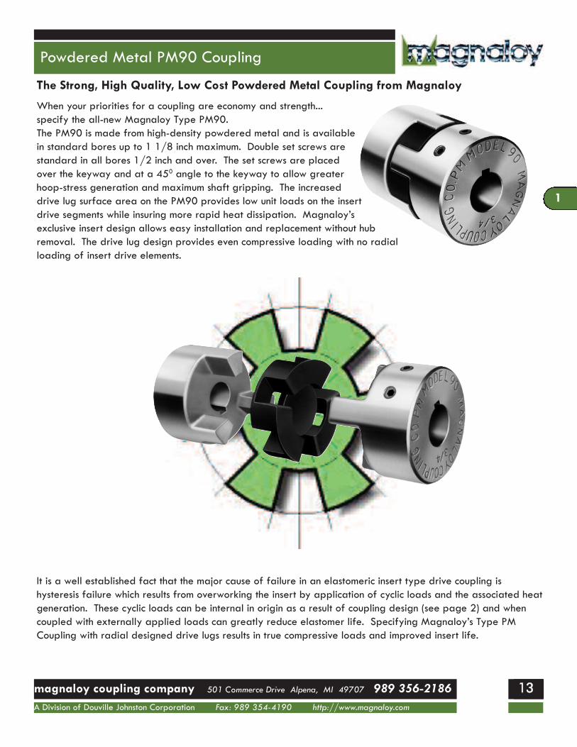
When your priorities for a coupling are economy and strength...specify the all-new Magnaloy Type PM90.The PM90 is made from high-density powdered metal and is available in standard bores up to 1 1/8 inch maximum. Double set screws are standard in all bores 1/2 inch and over. The set screws are placed over the keyway and at a 450 angle to the keyway to allow greater hoop-stress generation and maximum shaft gripping. The increased drive lug surface area on the PM90 provides low unit loads on the insert drive segments while insuring more rapid heat dissipation. Magnaloy’s exclusive insert design allows easy installation and replacement without hub removal. The drive lug design provides even compressive loading with no radialloading of insert drive elements.
Powdered Metal PM90 Coupling
1122magnaloy coupling company 501 Commerce Drive Alpena, MI 49707 989 356-2186A Division of Douville Johnston Corporation Fax: 989 354-4190 http://www.magnaloy.com
1133
1
The Strong, High Quality, Low Cost Powdered Metal Coupling from Magnaloy
It is a well established fact that the major cause of failure in an elastomeric insert type drive coupling is hysteresis failure which results from overworking the insert by application of cyclic loads and the associated heat generation. These cyclic loads can be internal in origin as a result of coupling design (see page 2) and whencoupled with externally applied loads can greatly reduce elastomer life. Specifying Magnaloy’s Type PM Coupling with radial designed drive lugs results in true compressive loads and improved insert life.
1

PM90 Specifications
1133 magnaloy coupling company 501 Commerce Drive Alpena, MI 49707 989 356-2186A Division of Douville Johnston Corporation Fax: 989 354-4190 http://www.magnaloy.com
1144
1
Model PM90 Performance Specifications
MaximumBore
MinimumBore
InsertNumber
TorqueRating(in lb)
HP Ratingper 100
RPM
TorsionalRigidity
(in lb/deg)
Complete CouplingApprox Weight (lb)
Wr2
(lb ft2)(solid)Solid Max Bore
1 1/8 7/16P097N7 224 0.36 38.3
1.8 1.3 0.946P097U9 336 0.54 69.9P097H5 672 1.08 158.7
Model PM90 Dimensional Specifications
A -B -T -W -X -Y -
Over all length (Assembled) - 2.78Outside Diameter - 2.125Set Screw Size - 1/4-20 UNC, 2 placesDistance between shaft ends - 3/16 minDistance between shaft ends - 3/4 maxHub movement required for insert removal - 1.20 total
N o t e s
11

PM90 Specifications
1144magnaloy coupling company 501 Commerce Drive Alpena, MI 49707 989 356-2186A Division of Douville Johnston Corporation Fax: 989 354-4190 http://www.magnaloy.com
1155
1
Model PM90 - Standard Bore / Keyway Sizes (per AGMA Class 1, Clearance Fit)
PartNumber
Bore & KeywayCombinations
Bore Size** Key Width Key DepthSet Screw
Size QuantityP090014N 7/16 x No Key 0.4375 / 0.4385 0.0938 / 0.0958 - 1/4-20 UNC 1
P09001403 7/16 x 3/32 0.4375 / 0.4385 0.125 / 0.127 0.484 / 0.495 1/4-20 UNC 1
P09001404 7/16 x 1/8 0.4375 / 0.4385 0.125 / 0.127 0.496 / 0.507 1/4-20 UNC 2
P09001604 1/2 x 1/8 0.500 / 0.501 0.125 / 0.127 0.560 / 0.571 1/4-20 UNC 2
P09001804 9/16 x 1/8 0.5625 / 0.5635 0.125 / 0.127 0.623 / 0.634 1/4-20 UNC 2
P09002005 5/8 x 5/32 0.625 / 0.626 0.1562 / 0.1582 0.698 / 0.709 1/4-20 UNC 2
P09002006 5/8 x 3/16 0.625 / 0.626 0.1875 / 0.1895 0.709 / 0.720 1/4-20 UNC 2
P09002206 11/16 x 3/16 0.6875 / 0.6885 0.1875 / 0.1895 0.773 / 0.784 1/4-20 UNC 2
P09002404 3/4 x 1/8 0.750 / 0.751 0.125 / 0.127 0.812 / 0.823 1/4-20 UNC 2
P09002406 3/4 x 3/16 0.750 / 0.751 0.1875 / 0.1895 0.837 / 0.848 1/4-20 UNC 2
P09002806 7/8 x 3/16 0.875 / 0.876 0.1875 / 0.1895 0.964 / 0.975 1/4-20 UNC 2
P09002808 7/8 x 1/4 0.875 / 0.876 0.250 / 0.252 0.982 / 0.993 1/4-20 UNC 2
P09010006 1 x 3/16 1.000 / 1.001 0.1875 / 0.1895 1.090 / 1.101 1/4-20 UNC 2
P09010008 1 x 1/4 1.000 / 1.001 0.250 / 0.252 1.114 / 1.125 1/4-20 UNC 2
P09010408 1 1/8 x 1/4 1.125 / 1.126 0.205 / 0.252 1.241 / 1.252 1/4-20 UNC 2
* Shaded combinations are Semi-special - see price sheet** Other Bore/Keyway combinations are available. Consult factory for quotation.
Model PM90 Bore Tolerances
Feature ToleranceBore -.000 / +.001
Key Width -.000 / +.002Key Depth +.005 / +.016
As with Magnaloy’s standard line of couplings, insert elastomer selection allows variable performance characteristics. Insert design eliminates metal-to-metal contact and assures electrical isolation of shafts.
Nitrile, 70A Durometer.....Standard elastomer material offering excellent resistance to petroleum products and superior compression set characteristics.Urethane, 90A Durometer.....Excellent mechanical and physical properties. Note:Urethane material tends to soften when exposed toelevated temperatures or humid conditions.Hytrel, 50D Durometer....Superior mechanical and physical properties and offers excellent fluid compatibility and high temperature characteristics.
Additional insert materials available upon request from factory.See page 8 for additional information on insert selection.
1

magnaloy coupling company 501 Commerce Drive Alpena, MI 49707 989 356-2186A Division of Douville Johnston Corporation Fax: 989 354-4190 http://www.magnaloy.com
1166
1