Magic Tutorial #1: Getting Started - boun.edu.tresaki.ee.boun.edu.tr/courses/ee537/magic-tut.pdf ·...
81
Magic Tutorial #1: Getting Started John Ousterhout (updated by others, too) Computer Science Division Electrical Engineering and Computer Sciences University of California Berkeley, CA 94720 This tutorial corresponds to Magic version 6. 1. What is Magic? Magic is an interactive system for creating and modifying VLSI circuit layouts. With Magic, you use a color graphics display and a mouse or graphics tablet to design basic cells and to combine them hierarchically into large structures. Magic is different from other layout editors you may have used. The most important difference is that Magic is more than just a color painting tool: it understands quite a bit about the nature of circuits and uses this information to provide you with additional operations. For example, Magic has built-in knowledge of layout rules; as you are editing, it continu- ously checks for rule violations. Magic also knows about connectivity and transistors, and contains a built-in hierarchical circuit extractor. Magic also has a plow operation that you can use to stretch or compact cells. Lastly, Magic has routing tools that you can use to make the global interconnections in your circuits. Magic is based on the Mead-Conway style of design. This means that it uses simplified design rules and circuit structures. The simplifications make it easier for you to design circuits and permit Magic to provide powerful assistance that would not be pos- sible otherwise. However, they result in slightly less dense circuits than you could get with more complex rules and structures. For example, Magic permits only Manhattan designs (those whose edges are vertical or horizontal). Circuit designers tell us that our conservative design rules cost 5-10% in density. We think that the density sacrifice is compensated for by reduced design time. 2. How to Get Help and Report Problems There are several ways you can get help about Magic. If you are trying to learn about the system, you should start off with the Magic tutorials, of which this is the first. Each tutorial introduces a particular set of facilities in Magic. There is also a set of -1-
Transcript of Magic Tutorial #1: Getting Started - boun.edu.tresaki.ee.boun.edu.tr/courses/ee537/magic-tut.pdf ·...

Magic Tutorial #1: Getting Started
John Ousterhout(updated by others, too)
Computer Science DivisionElectrical Engineering and Computer Sciences
University of CaliforniaBerkeley, CA 94720
This tutorial corresponds to Magic version 6.
1. What is Magic?
Magic is an interactive system for creating and modifying VLSI circuit layouts.With Magic, you use a color graphics display and a mouse or graphics tablet to designbasic cells and to combine them hierarchically into large structures. Magic is differentfrom other layout editors you may have used. The most important difference is thatMagic is more than just a color painting tool: it understands quite a bit about the natureof circuits and uses this information to provide you with additional operations. Forexample, Magic has built-in knowledge of layout rules; as you are editing, it continu-ously checks for rule violations. Magic also knows about connectivity and transistors,and contains a built-in hierarchical circuit extractor. Magic also has a plow operationthat you can use to stretch or compact cells. Lastly, Magic has routing tools that you canuse to make the global interconnections in your circuits.
Magic is based on the Mead-Conway style of design. This means that it usessimplified design rules and circuit structures. The simplifications make it easier for youto design circuits and permit Magic to provide powerful assistance that would not be pos-sible otherwise. However, they result in slightly less dense circuits than you could getwith more complex rules and structures. For example, Magic permits only Manhattandesigns (those whose edges are vertical or horizontal). Circuit designers tell us that ourconservative design rules cost 5-10% in density. We think that the density sacrifice iscompensated for by reduced design time.
2. How to Get Help and Report Problems
There are several ways you can get help about Magic. If you are trying to learnabout the system, you should start off with the Magic tutorials, of which this is the first.Each tutorial introduces a particular set of facilities in Magic. There is also a set of
- 1 -

Magic Tutorial #1: Getting Started September 19, 1990
iiiiiiiiiiiiiiiiiiiiiiiiiiiiiiiiiiiiiiiiiiiiiiiiiiiiiiiiiiiiiMagic Tutorial #1: Getting StartedMagic Tutorial #2: Basic Painting and SelectionMagic Tutorial #3: Advanced Painting (Wiring and Plowing)Magic Tutorial #4: Cell HierarchiesMagic Tutorial #5: Multiple WindowsMagic Tutorial #6: Design-Rule CheckingMagic Tutorial #7: Netlists and RoutingMagic Tutorial #8: Circuit ExtractionMagic Tutorial #9: Format Conversion for CIF and CalmaMagic Tutorial #10: The Interactive RouteMagic Tutorial #11: Using RSIM with MagiciiiiiiiiiiiiiiiiiiiiiiiiiiiiiiiiiiiiiiiiiiiiiiiiiiiiiiiiiiiiiMagic Maintainer’s Manual #1: Hints for System MaintainersMagic Maintainer’s Manual #2: The Technology FileMagic Maintainer’s Manual #3: Display Styles, Color Maps, and GlyphsMagic Maintainer’s Manual #4: Using Magic Under X WindowsiiiiiiiiiiiiiiiiiiiiiiiiiiiiiiiiiiiiiiiiiiiiiiiiiiiiiiiiiiiiiMagic Technology Manual #1: NMOSMagic Technology Manual #2: SCMOSiiiiiiiiiiiiiiiiiiiiiiiiiiiiiiiiiiiiiiiiiiiiiiiiiiiiiiiiiiiiiccccccccccccccccccccc
ccccccccccccccccccccc
Table I. The Magic tutorials, maintenance manuals, and technology manuals.
manuals intended for system maintainers. These describe things like how to create newtechnologies. Finally, there is a set of technology manuals. Each one of the technologymanuals describes the features peculiar to a particular technology, such as layer namesand design rules. Table I lists all of the Magic manuals. The tutorials are designed to beread while you are running Magic, so that you can try out the new commands as they areexplained. You needn’t read all the tutorials at once; each tutorial lists the other tutorialsthat you should read first.
The tutorials are not necessarily complete. Each one is designed to introduce a setof facilities, but it doesn’t necessarily cover every possibility. The ultimate authority onhow Magic works is the reference manual, which is a standard Unix man page. The manpage gives concise and complete descriptions of all the Magic commands. Once youhave a general idea how a command works, the man page is probably easier to consultthan the tutorial. However, the man page may not make much sense until after you’veread the tutorial.
A third way of getting help is available on-line through Magic itself. The :helpcommand will print out one line for each Magic command, giving the command’s syntaxand an extremely brief description of the command. This facility is useful if you’ve for-gotten the name or exact syntax of a command. After each screenful of help information,:help stops and prints ‘‘--More--’’. If you type a space, the next screenful of data will beoutput, and if you type q the rest of the output will be skipped. If you’re interested ininformation about a particular subject, you can type
:help subject
This command will print out each command description that contains the subject string.
- 2 -
Magic Tutorial #1: Getting Started September 19, 1990
If you have a question or problem that can’t be answered with any of the aboveapproaches, you may contact the Magic authors by sending mail [email protected] (or ucbvax!ucbarpa!magic). This will log your mes-sage in a file (so we can’t forget about it) and forward the message to the Magic main-tainers. Magic maintenance is a mostly volunteer effort, so when you report a bug or aska question, please be specific. Obviously, the more specific you are, the more likely wecan answer your question or reproduce the bug you found. We’ll tend to answer thespecific bug reports first, since they involve less time on our part. Try to describe theexact sequence of events that led to the problem, what you expected to happen, and whatactually happened. If possible, find a small example that reproduces the problem andsend us the relevant (small!) files so we can make it happen here. Or best of all, send usa bug fix along with a small example of the problem.
3. Graphics Configuration
Magic can be run with different graphics hardware. The most commonconfiguration is to run Magic under X11 on a workstation. Another way to run Magic ison a mainframe with a serial-line graphics display. The rest of this section concernsX11.
Before starting up magic, make sure that your DISPLAY variable is set correctly. Ifyou are running magic and your X server on the same machine, set it to unix:0:
setenv DISPLAY unix:0
Under X10, the layout window will appear in the upper left quadrant of your screen. TheX11 server will normally prompt you for the window’s position and size. This window isan ordinary X window, and can be moved and resized using the window manager.
For now, you can skip to the next major section: "Running Magic".
3.1. Advanced X Use
The X11 driver can read in window sizing and font preferences from your .Xde-faults file. The following specifications are recognized:
magic.window: 1000x600+10+10magic.newwindow: 300x300+400+100magic.small: helvetica8magic.medium: helvetica12magic.large: helvetica18magic.xlarge: helvetica24
magic.window is the size and position of the initial window, while magic.newwindow isthe size and position of subsequent windows. If these are left blank, you will beprompted to give the window’s position and size. small, medium, large, and xlarge arevarious fonts magic uses for labels. Some X11 servers read the .Xdefaults file only whenyou initially log in; you may have to log out and then back in again for the changes totake effect.
Under X11, Magic can run on a display of any depth for which there are colormapand dstyle files. Monochrome, 4 bit, 6 bit, and 7 bit files for Mos are distributed in thisrelease. You can explicitly specify how many planes Magic is to use by adding a suffix
- 3 -
Magic Tutorial #1: Getting Started September 19, 1990
numeral between 1 and 7 to "XWIND" when used with Magic’s "-d" option. For exam-ple, "magic -d XWIND1" runs magic on a monochrome display and "magic -dXWIND7" runs magic on a 7 plane display. If this number is not specified, magic checksthe depth of the display and picks the largest number in the set {1,4,6,7} that the displaywill support.
The X10 driver only supports monochrome and 7 bit displays.
3.2. Serial-line Displays
If you are running Magic on a mainframe, each station consists of a standard videoterminal, called the text display, and a color display. You use the keyboard on the textdisplay to type in commands, and Magic uses its screen to log the commands and theirresults. The color display is used to display one or more portions of the circuit you aredesigning. You will use a graphics tablet or mouse to point to things on the color displayand to invoke some commands. If there is a keyboard attached to the color display (as,for example, with AED512 displays) it is not used except to reset the display. Thecurrent version of Magic supports the AED family of displays. Most of the displays arenow available with special ROMs in them that provide extra Magic support (talk to yourlocal AED sales rep to make sure you get the UCB ROMs). More displays are beingadded, so check the Unix man page for the most up-to-date information.
4. Running Magic
From this point on, you should be sitting at a Magic workstation so you can experi-ment with the program as you read the manuals. Starting up Magic is usually pretty sim-ple. Just log in and, if needed, start up your favorite window system. Then type the shellcommand
magic tut1
Tut1 is the name of a library cell that you will play with in this tutorial. At this point,several colored rectangles should appear on the color display along with a white box anda cursor. A message will be printed on the text display to tell you that tut1 isn’t writable(it’s in a read-only library), and a ‘‘>’’ prompt should appear. If this has happened, thenyou can skip the rest of this section (except for the note below) and go directly to Section5.
Note: in the tutorials, when you see things printed in boldface, for example, magictut1 from above, they refer to things you type exactly, such as command names and filenames. These are usually case sensitive (A is different from a). When you see thingsprinted in italics, they refer to classes of things you might type. Arguments in squarebrackets are optional. For example, a more complete description of the shell commandfor Magic is
magic [file]
You could type any file name for file, and Magic would start editing that file. It turns outthat tut1 is just a file in Magic’s cell library. If you didn’t type a file name, Magic wouldload a new blank cell.
If things didn’t happen as they should have when you tried to run Magic, any ofseveral things could be wrong. If a message of the form ‘‘magic: Command not found’’
- 4 -
Magic Tutorial #1: Getting Started September 19, 1990
appears on your screen it is because the shell couldn’t find the Magic program. The moststable version of Magic is the directory ∼cad/bin, and the newest public version is in∼cad/new. You should make sure that both these directories are in your shell path. Nor-mally, ∼cad/new should appear before ∼cad/bin. If this sounds like gibberish, find a Unixhacker and have him or her explain to you about paths. If worst comes to worst, you caninvoke Magic by typing its full name:
∼cad/bin/magic tut1
Another possible problem is that Magic might not know what kind of display youare using. To solve this, use magic’s -d flag:
magic -d display tut1
Display is usually the model number of the workstation you are using or the name ofyour window system. Look in the manual page for a list of valid names, or just guesssomething. Magic will print out the list of valid names if you guess wrong.
If you are using a graphics terminal (not a workstation), it is possible that Magicdoesn’t know which serial line to use. To learn how to fix this, read about the -g switchin the magic(1) manual page. Also read the displays(5) manual page.
5. The Box and the Cursor
Two things, called the box and the cursor, are used to select things on the colordisplay. As you move the mouse, the cursor moves on the screen. The cursor starts outwith a crosshair shape, but you’ll see later that its shape changes as you work to providefeedback about what you’re doing. The left and right mouse buttons are used to positionthe box. If you press the left mouse button and then release it, the box will move so thatits lower left corner is at the cursor position. If you press and release the right mousebutton, the upper right corner of the box will move to the cursor position, but the lowerleft corner will not change. These two buttons are enough to position the box anywhereon the screen. Try using the buttons to place the box around each of the colored rectan-gles on the screen.
Sometimes it is convenient to move the box by a corner other than the lower left.To do this, press the left mouse button and hold it down. The cursor shape changes toshow you that you are moving the box by its lower left corner:
While holding the button down, move the cursor near the lower right corner of the box,and now click the right mouse button (i.e. press and release it, while still holding downthe left button). The cursor’s shape will change to indicate that you are now moving thebox by its lower right corner. Move the cursor to a different place on the screen andrelease the left button. The box should move so that its lower right corner is at the cursorposition. Try using this feature to move the box so that it is almost entirely off-screen tothe left. Try moving the box by each of its corners.
You can also reshape the box by corners other than the upper right. To do this,press the right mouse button and hold it down. The cursor shape shows you that you are
- 5 -
Magic Tutorial #1: Getting Started September 19, 1990
reshaping the box by its upper right corner:
Now move the cursor near some other corner of the box and click the left button, all thewhile holding the right button down. The cursor shape will change to show you that nowyou are reshaping the box by a different corner. When you release the right button, thebox will reshape so that the selected corner is at the cursor position but the diagonallyopposite corner is unchanged. Try reshaping the box by each of its corners.
6. Invoking Commands
Commands can be invoked in Magic in three ways: by pressing buttons on themouse; by typing single keystrokes on the text keyboard (these are called macros); or bytyping longer commands on the text keyboard (these are called long commands). Manyof the commands use the box and cursor to help guide the command.
To see how commands can be invoked from the buttons, first position the box over asmall blank area in the middle of the screen. Then move the cursor over the red rectan-gle and press the middle mouse button. At this point, the area of the box should getpainted red. Now move the cursor over empty space and press the middle button again.The red paint should go away. Note how this command uses both the cursor and boxlocations to control what happens.
As an example of a macro, type the g key on the text keyboard. A grid will appearon the color display, along with a small black box marking the origin of the cell. If youtype g again, the grid will go away. You may have noticed earlier that the box cornersdidn’t move to the exact cursor position: you can see now that the box is forced to fallon grid points.
Long commands are invoked by typing a colon (‘‘:’’) or semi-colon (‘‘;’’). Afteryou type the colon or semi-colon, the ‘‘>’’ prompt on the text screen will be replaced bya ‘‘:’’ prompt. This indicates that Magic is waiting for a long command. At this pointyou should type a line of text, followed by a return. When the long command has beenprocessed, the ‘‘>’’ prompt reappears on the text display. Try typing semi-colon fol-lowed by return to see how this works. Occasionally a ‘‘]’’ (right bracket) prompt willappear. This means that the design-rule checker is reverifying part of your design. Fornow you can just ignore this and treat ‘‘]’’ like ‘‘>’’.
Each long command consists of the name of the command followed by arguments,if any are needed by that command. The command name can be abbreviated, just as longas you type enough characters to distinguish it from all other long commands. For exam-ple, :h and :he may be used as abbreviations for :help. On the other hand, :u may not beused as an abbreviation for :undo because there is another command, :upsidedown, thathas the same abbreviation. Try typing :u.
As an example of a long command, put the box over empty space on the colordisplay, then invoke the long command
- 6 -
Magic Tutorial #1: Getting Started September 19, 1990
:paint red
The box should fill with the red color, just as if you had used the middle mouse button topaint it. Everything you can do in Magic can be invoked with a long command. It turnsout that the macros are just conveniences that are expanded into long commands and exe-cuted. For example, the long command equivalent to the g macro is
:grid
Magic permits you to define new macros if you wish. Once you’ve become familiar withMagic you’ll almost certainly want to add your own macros so that you can invokequickly the commands you use most frequently. See the magic(1) man page under thecommand :macro.
One more long command is of immediate use to you. It is
:quit
Invoke this command. Note that before exiting, Magic will give you one last chance tosave the information that you’ve modified. Type y to exit without saving anything.
- 7 -
Magic Tutorial #2: Basic Painting and Selection
John Ousterhout
Computer Science DivisionElectrical Engineering and Computer Sciences
University of CaliforniaBerkeley, CA 94720
(Updated by others, too.)
This tutorial corresponds to Magic version 6.
Tutorials to read first:
Magic Tutorial #1: Getting Started
Commands introduced in this tutorial:
:box, :clockwise, :copy, :erase, :findbox :grid, :label, :layers, :macro, :move, :paint,:redo, :save, :select, :sideways, :undo, :upsidedown, :view, :what, :writeall, :zoom
Macros introduced in this tutorial:
a, A, c, d, ˆD, e, E, g, G, q, Q, r, R, s, S, t, T, u, U, v, w, W, z, Z, 4
1. Cells and Paint
In Magic, a circuit layout is a hierarchical collection of cells. Each cell containsthree things: colored shapes, called paint, that define the circuit’s structure; textual labelsattached to the paint; and subcells, which are instances of other cells. The paint is whatdetermines the eventual function of the VLSI circuit. Labels and subcells are a conveni-ence for you in managing the layout and provide a way of communicating informationbetween various synthesis and analysis tools. This tutorial explains how to create andedit paint and labels in simple single-cell designs, using the basic painting commands.‘‘Magic Tutorial #3: Advanced Painting (Wiring and Plowing)’’ describes some moreadvanced features for manipulating paint. For information on how to build up cellhierarchies, see ‘‘Magic Tutorial #4: Cell Hierarchies’’.
- 1 -
Magic Tutorial #2: Basic Painting and Selection September 19, 1990
2. Painting and Erasing
Enter Magic to edit the cell tut2a (type magic tut2a to the Unix shell; follow thedirections in ‘‘Tutorial #1: Getting Started’’ if you have any problems with this). Thetut2a cell is a sort of palette: it shows a splotch of each of several paint layers and givesthe names that Magic uses for the layers.
The two basic layout operations are painting and erasing. They can be invokedusing the :paint and :erase long commands, or using the buttons. The easiest way topaint and erase is with the mouse buttons. To paint, position the box over the area you’dlike to paint, then move the cursor over a color and click the middle mouse button. Toerase everything in an area, place the box over the area, move the cursor over a blankspot, and click the middle mouse button. Try painting and erasing various colors. If thescreen gets totally messed up, you can always exit Magic and restart it. While you’repainting, white dots may occasionally appear and disappear. These are design rule viola-tions detected by Magic, and will be explained in ‘‘Magic Tutorial #6: Design RuleChecking’’. You can ignore them for now.
It’s completely legal to paint one layer on top of another. When this happens, oneof three things may occur. In some cases, the layers are independent, so what you’ll seeis a combination of the two, as if each were a transparent colored foil. This happens, forexample, if you paint metal1 (blue) on top of polysilicon (red). In other cases, when youpaint one layer on top of another you’ll get something different from either of the twooriginal layers. For example, painting poly on top of ndiff produces ntransistor (try this).In still other cases the new layer replaces the old one: this happens, for example, if youpaint a pcontact on top of ntransistor. Try painting different layers on top of each otherto see what happens. The meaning of the various layers is discussed in more detail inSection 11 below.
There is a second way of erasing paint that allows you to erase some layers withoutaffecting others. This is the macro ˆD (control-D, for ‘‘Delete paint’’). To use it, posi-tion the box over the area to be erased, then move the crosshair over a splotch of paintcontaining the layer(s) you’d like to erase. Type ˆD key on the text keyboard: the colorsunderneath the cursor will be erased from the area underneath the box, but no otherlayers will be affected. Experiment around with the ˆD macro to try different combina-tions of paints and erases. If the cursor is over empty space then the ˆD macro isequivalent to the middle mouse button: it erases everything.
You can also paint and erase using the long commands
:paint layers:erase layers
In each of these commands layers is one or more layer names separated by commas (youcan also use spaces for separators, but only if you enclose the entire list in double-quotes). Any layer can be abbreviated as long as the abbreviation is unambiguous. Forexample, :paint poly,metal1 will paint the polysilicon and metal1 layers. The macro ˆDis predefined by Magic to be :erase $ ($ is a pseudo-layer that means ‘‘all layers under-neath the cursor’’).
- 2 -
Magic Tutorial #2: Basic Painting and Selection September 19, 1990
3. Undo
There are probably going to be times when you’ll do things that you’ll later wishyou hadn’t. Fortunately, Magic has an undo facility that you can use to restore thingsafter you’ve made mistakes. The command
:undo
(or, alternatively, the macro u) will undo the effects of the last command you invoked. Ifyou made a mistake several commands back, you can type :undo several times to undosuccessive commands. However, there is a limit to all this: Magic only remembers howto undo the last ten or so commands. If you undo something and then decide you wantedit after all, you can undo the undo with the command
:redo
(U is a macro for this command). Try making a few paints and erases, then use :undoand :redo to work backwards and forwards through the changes you made.
4. The Selection
Once you have painted a piece of layout, there are several commands you caninvoke to modify the layout. Many of them are based on the selection: you select one ormore pieces of the design, and then perform operations such as copying, deletion, androtation on the selected things. To see how the selection works, load cell tut2b. You cando this by typing :load tut2b if you’re still in Magic, or by starting up Magic with theshell command magic tut2b.
The first thing to do is to learn how to select. Move the cursor over the upper por-tion of the L-shaped blue area in tut2b, and type s, which is a macro for :select. The boxwill jump over to cover the vertical part of the ‘‘L’’. This operation selected a chunk ofmaterial. Move the box away from the chunk, and you’ll see that a thin white outline isleft around the chunk to show that it’s selected. Now move the cursor over the verticalred bar on the right of the cell and type s. The box will move over that bar, and the selec-tion highlighting will disappear from the blue area.
If you type s several times without moving the cursor, each command selects aslightly larger piece of material. Move the cursor back over the top of the blue ‘‘L’’, andtype s three times without moving the cursor. The first s selects a chunk (a rectangularregion all of the same type of material). The second s selects a region (all of the bluematerial in the region underneath the cursor, rectangular or not). The third s selects a net(all of the material that is electrically connected to the original chunk; this includes theblue metal, the red polysilicon, and the contact that connects them).
The macro S (short for :select more) is just like s except that it adds on to the selec-tion, rather than replacing it. Move the cursor over the vertical red bar on the right andtype S to see how this works. You can also type S multiple times to add regions and netsto the selection.
If you accidentally type s or S when the cursor is over space, you’ll select a cell(tut2b in this case). You can just undo this for now. Cell selection will be discussed in‘‘Magic Tutorial #4: Cell Hierarchies’’.
- 3 -

Magic Tutorial #2: Basic Painting and Selection September 19, 1990
You can also select material by area: place the box around the material you’d liketo select and type a (short for :select area). This will select all of the material under-neath the box. You can use the macro A to add material to the selection by area, and youcan use the long command
:select [more] area layers
to select only material on certain layers. Place the box around everything in tut2b andtype :select area metal1 followed by :select more area poly.
If you’d like to clear out the selection without modifying any of the selectedmaterial, you can use the command
:select clear
or type the macro C. You can clear out just a portion of the selection by typing :selectless or :select less area layers; the former deselects paint in the order that :select selectspaint, while the latter deselects paint under the box (just as :select area selects paintunder the box). For a synopsis of all the options to the :select command, type
:select help
5. Operations on the Selection
Once you’ve made a selection, there are a number of operations you can perform onit:
:delete:move [direction [distance]]
:stretch [direction [distance]]:copy
:upsidedown:sideways
:clockwise [degrees]
The :delete command deletes everything that’s selected. Watch out: :delete is differentfrom :erase, which erases paint from the area underneath the box. Select the red bar onthe right in tut2b and type d, which is a macro for :delete. Undo the deletion with the umacro.
The :move command picks up both the box and the selection and moves them sothat the lower-left corner of the box is at the cursor location. Select the red bar on theright and move it so that it falls on top of the vertical part of the blue ‘‘L’’. You can uset (‘‘translate’’) as a macro for :move. Practice moving various things around the screen.The command :copy and its macro c are just like :move except that a copy of the selec-tion is left behind at the original position.
There is also a longer form of the :move command that you can use to move theselection a precise amount. For example, :move up 10 will move the selection (and thebox) up 10 units. The direction argument can be any direction like left, south, down,etc. See the Magic manual page for a complete list of the legal directions. The macros
- 4 -
Magic Tutorial #2: Basic Painting and Selection September 19, 1990
q, w, e, and r are defined to move the selection left, down, up, and right (respectively) byone unit.
The :stretch command is similar to :move except that it stretches and erases as itmoves. :stretch does not operate diagonally, so if you use the cursor to indicate whereto stretch to, Magic will either stretch up, down, left, or right, whichever is closest. The:stretch command moves the selection and also does two additional things. First, foreach piece of paint that moves, :stretch will erase that layer from the region that thepaint passes through as it moves, in order to clear material out of its way. Second, if theback edge of a piece of selected paint touches non-selected material, one of the twopieces of paint is stretched to maintain the connection. The macros Q, W, E, and R justlike the macros q, etc. described above for :move. The macro T is predefined to:stretch. To see how stretching works, select the horizontal piece of the green wire intut2b and type W, then E. Stretching only worries about material in front of and behindthe selection; it ignores material to the sides (try the Q and R macros to see). You canuse plowing (described in Tutorial #3) if this is a problem.
The command :upsidedown will flip the selection upside down, and :sideways flipsthe selection sideways. Both commands leave the selection so it occupies the same totalarea as before, but with the contents flipped. The command :clockwise will rotate theselection clockwise, leaving the lower-left corner of the new selection at the same placeas the lower-left corner of the old selection. Degrees must be a multiple of 90, anddefaults to 90.
At this point you know enough to do quite a bit of damage to the tut2b cell. Exper-iment with the selection commands. Remember that you can use :undo to back out oftrouble.
6. Labels
Labels are pieces of text attached to the paint of a cell. They are used to provideinformation to other tools that will process the circuit. Most labels are node names: theyprovide an easy way of referring to nodes in tools such as routers, simulators, and timinganalyzers. Labels may also be used for other purposes: for example, some labels aretreated as attributes that give Crystal, the timing analyzer, information about the direc-tion of signal flow through transistors.
Load the cell tut2c and place a cross in the middle of the red chunk (to make across, position the lower-left corner of the box with the left button and then click theright button to place the upper-right corner on top of the lower-left corner). Then typetype the command :label test. A new label will appear at the position of the box. Thecomplete syntax of the :label command is
:label [text [position [layer]]]
Text must be supplied, but the other arguments can be defaulted. If text has any spaces init, then it must be enclosed in double quotes. Position tells where the text should bedisplayed, relative to the point of the label. It may be any of north, south, east, west,top, bottom, left, right, up, down, center, northeast, ne, southeast, se, southwest, sw,northwest, nw. For example, if ne is given, the text will be displayed above and to theright of the label point. If no position is given, Magic will pick a position for you. Layer
- 5 -

Magic Tutorial #2: Basic Painting and Selection September 19, 1990
tells which paint layer to attach the label to. If layer covers the entire area of the label,then the label will be associated with the particular layer. If layer is omitted, or if itdoesn’t cover the label’s area, Magic initially associates the label with the ‘‘space’’ layer,then checks to see if there’s a layer that covers the whole area. If there is, Magic movesthe label to that layer. It is generally a bad idea to place labels at points where there areseveral paint layers, since it will be hard to tell which layer the label is attached to. Asyou edit, Magic will ensure that labels are only attached to layers that exist everywhereunder the label. To see how this works, paint the layer pdiff (brown) over the label youjust created: the label will switch layers. Finally, erase poly over the area, and the labelwill move again.
Although many labels are point labels, this need not be the case. You can label anyrectangular area by setting the box to that area before invoking the label command. Thisfeature is used for labelling terminals for the router (see below), and for labelling tilesused by Mpack, the tile packing program. Tut2c has examples of point, line, and rec-tangular labels.
All of the selection commands apply to labels as well as paint. Whenever youselect paint, the labels attached to that paint will also be selected. Selected labels arehighlighted in white. Select some of the chunks of paint in tut2c to see how the labelsare selected too. When you use area selection, labels will only be selected if they arecompletely contained in the area being selected. If you’d like to select just a labelwithout any paint, make the box into a cross and put the cross on the label: s and S willselect just the label.
There are several ways to erase a label. One way is to select and then delete it.Another way is to erase the paint that the label is attached to. If the paint is erased allaround the label, then Magic will delete the label too. Try attaching a label to a red area,then paint blue over the red. If you erase blue the label stays (since it’s attached to red),but if you erase the red then the label is deleted.
You can also erase labels using the :erase command and the pseudo-layer labels.The command
:erase labels
will erase all labels that lie completely within the area of the box. Finally, you can erasea label by making the box into a cross on top of the label, then clicking the middle buttonwith the cursor over empty space. Technically, this will erase all paint layers and labelstoo. However, since the box has zero area, erasing paint has no effect: only the labelsare erased.
7. Labelling Conventions
When creating labels, Magic will permit you to use absolutely any text whatsoever.However, many other tools, and even parts of Magic, expect label names to observe cer-tain conventions. Except for the special cases described below, labels shouldn’t containany of the characters ‘‘/$@!ˆ’’. Spaces, control characters, or parentheses within labelsare probably a bad idea too. Many of the programs that process Magic output have theirown restrictions on label names, so you should find out about the restrictions that apply atyour site. Most labels are node names: each one gives a unique identification to a set of
- 6 -

Magic Tutorial #2: Basic Painting and Selection September 19, 1990
things that are electrically connected. There are two kinds of node names, local and glo-bal. Any label that ends in ‘‘!’’ is treated as a global node name; it will be assumed thatall nodes by this name, anywere in any cell in a layout, are electrically connected. Themost common global names are Vdd! and GND!, the power rails. You should alwaysuse these names exactly, since many other tools require them. Nobody knows why‘‘GND!’’ is all in capital letters and ‘‘Vdd!’’ isn’t.
Any label that does not end in ‘‘!’’ or any of the other special characters discussedbelow is a local node name. It refers to a node within that particular cell. Local nodenames should be unique within the cell: there shouldn’t be two electrically distinct nodeswith the same name. On the other hand, it is perfectly legal, and sometimes advanta-geous, to give more than one name to the same node. It is also legal to use the same localnode name in different cells: the tools will be able to distinguish between them and willnot assume that they are electrically connected.
The only other labels currently understood by the tools are attributes. Attributes arepieces of text associated with a particular piece of the circuit: they are not node names,and need not be unique. For example, an attribute might identify a node as a chip input,or it might identify a transistor terminal as the source of information for that transistor.Any label whose last character is ‘‘@’’, ‘‘$’’, or ‘‘ˆ’’ is an attribute. There are three dif-ferent kinds of attributes. Node attributes are those ending with ‘‘@’’; they are associ-ated with particular nodes. Transistor source/drain attributes are those ending in ‘‘$’’;they are associated with particular terminals of a transistor. A source or drain attributemust be attached to the channel region of the transistor and must fall exactly on thesource or drain edge of the transistor. The third kind of attribute is a transistor gate attri-bute. It ends in ‘‘ˆ’’ and is attached to the channel region of the transistor. To see exam-ples of attributes and node names, edit the cell tut2d in Magic.
Special conventions apply to labels for routing terminals. The standard Magicrouter (invoked by :route) ignores all labels except for those on the edges of cells. (Thisrestriction does not apply to the gate-array router, Garoute, or to the interactive router,Iroute). If you expect to use the standard router to connect to a particular node, youshould place the label for that node on its outermost edge. The label should not be apoint label, but should instead be a horizontal or vertical line covering the entire edge ofthe wire. The router will choose a connection point somewhere along the label. A goodrule of thumb is to label all nodes that enter or leave the cell in this way. For moredetails on how labels are used by the standard router, see ‘‘Magic Tutorial #7: Netlistsand Routing’’. Other labeling conventions are used by the Garouter and Irouter, consulttheir respective tutorials for details.
8. Files and Formats
Magic provides a variety of ways to save your cells on disk. Normally, things aresaved in a special Magic format. Each cell is a separate file, and the name of the file isjust the name of the cell with .mag appended. For example, the cell tut2a is saved in filetut2a.mag. To save cells on disk, invoke the command
:writeall
This command will run through each of the cells that you have modified in this editingsession, and ask you what to do with the cell. Normally, you’ll type write, or just hit the
- 7 -

Magic Tutorial #2: Basic Painting and Selection September 19, 1990
return key, in which case the cell will be written back to the disk file from which it wasread (if this is a new cell, then you’ll be asked for a name for the cell). If you typeautowrite, then Magic will write out all the cells that have changed without asking youwhat to do on a cell-by-cell basis. Flush will cause Magic to delete its internal copy ofthe cell and reload the cell from the disk copy, thereby expunging all edits that you’vemade. Skip will pass on to the next cell without writing this cell (but Magic stillremembers that it has changed, so the next time you invoke :writeall Magic will askabout this cell again). Abort will stop the command immediately without writing orchecking any more cells.
IMPORTANT NOTE: Unlike vi and other text editors, Magic doesn’t keepcheckpoint files. This means that if the system should crash in the middle of a session,you’ll lose all changes since the last time you wrote out cells. It’s a good idea to saveyour cells frequently during long editing sessions.
You can also save the cell you’re currently editing with the command
:save name
This command will append ‘‘.mag’’ to name and save the cell you are editing in thatlocation. If you don’t provide a name, Magic will use the cell’s name (plus the ‘‘.mag’’extension) as the file name, and it will prompt you for a name if the cell hasn’t yet beennamed.
Once a cell has been saved on disk you can edit it by invoking Magic with the com-mand
magic name
where name is the same name you used to save the cell (no ‘‘.mag’’ extension).
Magic can also read and write files in CIF and Calma Stream formats. See ‘‘MagicTutorial #9: Format Conversion for CIF and Calma’’ for details.
9. Plotting
Magic can generate hardcopy plots of layouts in four ways: versatec (black-and-white or color), gremlin and pixels (a generalized pixel-file that can be massaged in manyways). The first style is for printers like the black-and-white Versatec family: for these,Magic will output a raster file and spool the file for printing. To plot part of your design,place the box around the part you’d like to plot and type
:plot versatec [width [layers]]
This will generate a plot of the area of the box. Everything visible underneath the boxwill appear in more-or-less the same way in the plot. Width specifies how wide the plotwill be, in inches. Magic will scale the plot so that the area of the box comes out thiswide. The default for width is the width of the plotter (if width is larger than the plotterwidth, it’s reduced to the plotter width). If layers is given, it specifies exactly what infor-mation is to be plotted. Only those layers will appear in the plot. The special ‘‘layer’’labels will enable label plotting.
The second form is for driving printers like color Versatecs. It is enabled by settingthe color plot parameter to true. A table of stipples for the primary colors (black, cyan,
- 8 -

Magic Tutorial #2: Basic Painting and Selection September 19, 1990
magenta abd yellow) is given in the technology file. When the plot command is given,four rasters (one for each of the colors) are generated, separated with the proper controlsequences for the printer. Otherwise, operation is exactly as for the black-and-whitecase.
The third form of plotting is for generating Gremlin-format files, which can then beedited with the Gremlin drawing system or included in documents processed by Grn andDitroff. The command to get Gremlin files is
:plot gremlin file [layers]
It will generate a Gremlin-format file in file that describes everything underneath the box.If layers is specified, it indicates which layers are to appear in the file; otherwise every-thing visible on the screen is output. The Gremlin file is output without any particularscale; use the width or height commands in Grn to scale the plot when it’s printed. Youshould use the mg stipples when printing Magic Gremlin plots; these will produce thesame stipple patterns as :plot versatec.
Finally, the ‘‘pixels’’ style of plotting generates a file of pixel values for the regionto be plotted. This can be useful for input to other image tools, or for generation of slidesand viewgraphs for presentations. The file consists of a sequence of bytes, three for eachpixel, written from left to right and top to bottom. Each three bytes represent the red,green and blue values used to display the pixel. Thus, if the upper-left-most pixel wereto be red, the first three bytes of the file would have values of 255, 0 and 0.
The resolution of the generated file is normally 512, but can be controlled by settingthe plot parameter pixWidth. It must be a multiple of 8; Magic will round up if an inap-propriate value is entered. The height of the file is determined by the shape of the box.In any case, the actual resolution of the file is appended to the file name. For example,plotting a square region, 2048 pixels across, will result in a file named something like‘‘magicPlot1234a-2048-2048’’.
There are several plotting parameters used internally to Magic, such as the width ofthe Versatec printer and the number of dots per inch on the Versatec printer. You canmodify most of these to work with different printers. For details, read about the various:plot command options in the man page.
10. Utility Commands
There are several additional commands that you will probably find useful once youstart working on real cells. The command
:grid [spacing]:grid xSpacing ySpacing
:grid xSpacing ySpacing xOrigin yOrigin:grid off
will display a grid over your layout. Initially, the grid has a one-unit spacing. Typing:grid with no arguments will toggle the grid on and off. If a single numerical argumentis given, the grid will be turned on, and the grid lines will be spacing units apart. Themacro g provides a short form for :grid and G is short for :grid 2. If you provide twoarguments to :grid, they are the x- and y-spacings, which may be different. If you
- 9 -
Magic Tutorial #2: Basic Painting and Selection September 19, 1990
provide four arguments, the last two specify a reference point through which horizontaland vertical grid lines pass; the default is to use (0,0) as the grid origin. The command:grid off always turns the grid off, regardless of whether or not is was previously on.When the grid is on, a small black box is displayed to mark the (0,0) coordinate of thecell you’re editing.
If you want to create a cell that doesn’t fit on the screen, you’ll need to know how tochange the screen view. This can be done with three commands:
:zoom factor:findbox [zoom]
:view
If factor is given to the zoom command, it is a zoom-out factor. For example, the com-mand :zoom 2 will change the view so that there are twice as many units across thescreen as there used to be (Z is a macro for this). The new view will have the samecenter as the old one. The command :zoom .5 will increase the magnification so thatonly half as much of the circuit is visible.
The :findbox command is used to change the view according to the box. The com-mand alone just moves the view (without changing the scale factor) so that the box is inthe center of the screen. If the zoom argument is given then the magnification is changedtoo, so that the area of the box nearly fills the screen. z is a macro for :findbox zoom andB is a macro for :findbox.
The command :view resets the view so that the entire cell is visible in the window.It comes in handy if you get lost in a big layout. The macro v is equivalent to :view.
The command :box prints out the size and location of the box in case you’d like tomeasure something in your layout. The macro b is predefined to :box. The :box com-mand can also be used to set the box to a particular location, height, or width. See theman page for details.
The command
:what
will print out information about what’s selected. This may be helpful if you’re not surewhat layer a particular piece of material is, or what layer a particular label is attached to.
If you forget what a macro means, you can invoke the command
:macro [char]
This command will print out the long command that’s associated with the macro char. Ifyou omit char, Magic will print out all of the macro associations. The command
:macro char command
We set up char to be a macro for command, replacing the old char macro if there wasone. If command contains any spaces then it must be enclosed in double-quotes. To seehow this works, type the command :macro 1 "echo You just typed the 1 key.", thentype the 1 key.
One of the macros, ‘‘.’’, has special meaning in Magic. This macro is alwaysdefined by the system to be the last long command you typed. Whenever you’d like torepeat a long command, all you have to do is use the dot macro.
- 10 -

Magic Tutorial #2: Basic Painting and Selection September 19, 1990
11. What the Layers Mean
The paint layers available in Magic are different from those that you may be used toin Caesar and other systems because they don’t correspond exactly to the masks used infabrication. We call them abstract layers because they correspond to constructs such aswires and contacts, rather than mask layers. We also call them logs because they looklike sticks except that the geometry is drawn fully fleshed instead of as lines. In Magicthere is one paint layer for each kind of conducting material (polysilicon, ndiffusion,metal1, etc.), plus one additional paint layer for each kind of transistor (ntransistor,ptransistor, etc.), and, finally, one further paint layer for each kind of contact (pcontact,ndcontact, m2contact, etc.) Each layer has one or more names that are used to refer tothat layer in commands. To find out the layers available in the current technology, typethe command
:layers
In addition to the mask layers, there are a few pseudo-layers that are valid in all technolo-gies; these are listed in Table I. Each Magic technology also has a technology manualdescribing the features of that technology, such as design rules, routing layers, CIF styles,etc. If you haven’t seen any of the technology manuals yet, this is a good time to take alook at the one for your process.
iiiiiiiiiiiiiiiiiiiiiiiiiiiiiiiiiierrors (design-rule violations)labelssubcells* (all mask layers)$ (all mask layers visible under cursor)iiiiiiiiiiiiiiiiiiiiiiiiiiiiiiiiiicccccc
cccccc
Table I. Pseudo-layers available in all technologies.
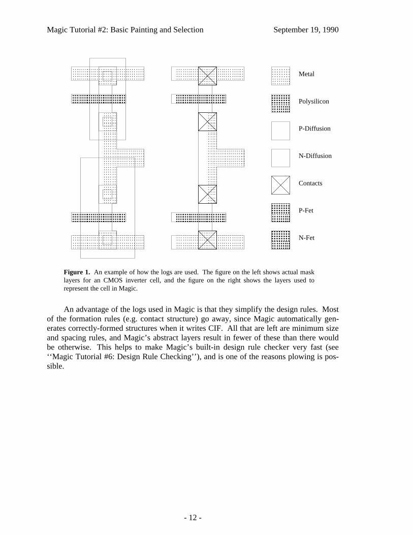
If you’re used to designing with mask layers (e.g. you’ve been reading the Mead-Conway book), Magic’s log style will take some getting used to. One of the reasons forlogs is to save you work. In Magic you don’t draw implants, wells, buried windows, orcontact via holes. Instead, you draw the primary conducting layers and paint some oftheir overlaps with special types such as n-transistor or polysilicon contact. For transis-tors, you draw only the actual area of the transistor channel. Magic will generate thepolysilicon and diffusion, plus any necessary implants, when it creates a CIF file. Forcontacts, you paint the contact layer in the area of overlap between the conducting layers.Magic will generate each of the constituent mask layers plus vias and buried windowswhen it writes the CIF file. Figure 1 shows a simple cell drawn with both mask layers (asin Caesar) and with logs (as in Magic). If you’re curious about what the masks will looklike for a particular layout, you can use the :cif see command to view the mask informa-tion.
- 11 -
Magic Tutorial #2: Basic Painting and Selection September 19, 1990
Metal
Polysilicon
N-Diffusion
P-Diffusion
Contacts
N-Fet
P-Fet
Figure 1. An example of how the logs are used. The figure on the left shows actual masklayers for an CMOS inverter cell, and the figure on the right shows the layers used torepresent the cell in Magic.
An advantage of the logs used in Magic is that they simplify the design rules. Mostof the formation rules (e.g. contact structure) go away, since Magic automatically gen-erates correctly-formed structures when it writes CIF. All that are left are minimum sizeand spacing rules, and Magic’s abstract layers result in fewer of these than there wouldbe otherwise. This helps to make Magic’s built-in design rule checker very fast (see‘‘Magic Tutorial #6: Design Rule Checking’’), and is one of the reasons plowing is pos-sible.
- 12 -

Magic Tutorial #3: Advanced Painting (Wiring and Plowing)
John OusterhoutWalter Scott
Computer Science DivisionElectrical Engineering and Computer Sciences
University of CaliforniaBerkeley, CA 94720
(Updated by others, too.)
This tutorial corresponds to Magic version 6.
Tutorials to read first:
Magic Tutorial #1: Getting StartedMagic Tutorial #2: Basic Painting and Selection
Commands introduced in this tutorial:
:array, :corner, :fill, :flush, :plow, :straighten, :tool, :wire
Macros introduced in this tutorial:
<space>
1. Introduction
Tutorial #2 showed you the basic facilities for placing paint and labels, selecting,and manipulating the things that are selected. This tutorial describes two additional facil-ities for manipulating paint: wiring and plowing. These commands aren’t absolutelynecessary, since you can achieve the same effect with the simpler commands of Tutorial#2; however, wiring and plowing allow you to perform certain kinds of manipulationsmuch more quickly than you could otherwise. Wiring is described in Section 2; itallows you to place wires by pointing at the ends of legs rather than by positioning thebox, and also provides for convenient contact placement. Plowing is the subject of Sec-tion 3. It allows you to re-arrange pieces of your circuit without having to worry aboutdesign-rule violations being created: plowing automatically moves things out of the wayto avoid trouble.
- 1 -
Magic Tutorial #3: Wiring and Plowing September 19, 1990
2. Wiring
The box-and-painting paradigm described in Tutorial #2 is sufficient to create anypossible layout, but it’s relatively inefficient since three keystrokes are required to painteach new area: two button clicks to position the box and one more to paint the material.This section describes a different painting mechanism based on wires. At any giventime, there is a current wiring material and wire thickness. With the wiring interface youcan create a new area of material with a single button click: this paints a straight-linesegment of the current material and width between the end of the previous wire segmentand the cursor location. Each additional button click adds an additional segment. Thewiring interface also makes it easy for you to place contacts.
2.1. Tools
Before learning about wiring, you’ll need to learn about tools. Until now, whenyou’ve pressed mouse buttons in layout windows the buttons have caused the box tochange or material to be painted. The truth is that buttons can mean different things atdifferent times. The meaning of the mouse buttons depends on the current tool. Eachtool is identified by a particular cursor shape and a particular interpretation of the mousebuttons. Initially, the current tool is the box tool; when the box tool is active the cursorhas the shape of a crosshair. To get information about the current tool, you can type thelong command
:tool info
This command prints out the name of the current tool and the meaning of the buttons.Run Magic on the cell tut3a and type :tool info.
The :tool command can also be used to switch tools. Try this out by typing thecommand
:tool
Magic will print out a message telling you that you’re using the wiring tool, and the cur-sor will change to an arrow shape. Use the :tool info command to see what the buttonsmean now. You’ll be using the wiring tool for most of the rest of this section. Themacro ‘‘ ’’ (space) corresponds to :tool. Try typing the space key a few times: Magicwill cycle circularly through all of the available tools. There are three tools in Magicright now: the box tool, which you already know about, the wiring tool, which you’lllearn about in this tutorial, and the netlist tool, which has a square cursor shape and isused for netlist editing. ‘‘Tutorial #7: Netlists and Routing’’ will show you how to usethe netlist tool.
The current tool affects only the meanings of the mouse buttons. It does not changethe meanings of the long commands or macros. This means, for example, that you canstill use all the selection commands while the wiring tool is active. Switch tools to thewiring tool, point at some paint in tut3a, and type the s macro. A chunk gets selectedjust as it does with the box tool.
- 2 -

Magic Tutorial #3: Wiring and Plowing September 19, 1990
2.2. Basic Wiring
There are three basic wiring commands: selecting the wiring material, adding aleg, and adding a contact. This section describes the first two commands. At this pointyou should be editing the cell tut3a with the wiring tool active. The first step in wiring isto pick the material and width to use for wires. This can be done in two ways. The easi-est way is to find a piece of material of the right type and width, point to it with the cur-sor, and click the left mouse button. Try this in tut3a by pointing to the label 1 and left-clicking. Magic prints out the material and width that it chose, selects a square of thatmaterial and width around the cursor, and places the box around the square. Try pointingto various places in tut3a and left-clicking.
Once you’ve selected the wiring material, the right button paints legs of a wire.Left-click on label 1 to select the red material, then move the cursor over label 2 andright-click. This will paint a red wire between 1 and 2. The new wire leg is selected sothat you can modify it with selection commands, and the box is placed over the tip of theleg to show you the starting point for the next wire leg. Add more legs to the wire byright-clicking at 3 and then 4. Use the mouse buttons to paint another wire in blue from5 to 6 to 7.
Each leg of a wire must be either horizontal or vertical. If you move the cursordiagonally, Magic will still paint a horizontal or vertical line (whichever results in thelongest new wire leg). To see how this works, left-click on 8 in tut3a, then right-click on9. You’ll get a horizontal leg. Now undo the new leg and right-click on 10. This timeyou’ll get a vertical leg. You can force Magic to paint the next leg in a particular direc-tion with the commands
:wire horizontal:wire vertical
Try out this feature by left-clicking on 8 in tut3a, moving the cursor over 10, and typing:wire ho (abbreviations work for :wire command options just as they do elsewhere inMagic). This command will generate a short horizontal leg instead of a longer verticalone.
2.3. Contacts
When the wiring tool is active, the middle mouse button places contacts. Undo allof your changes to tut3a by typing the command :flush and answering yes to the ques-tion Magic asks. This throws away all of the changes made to the cell and re-loads itfrom disk. Draw a red wire leg from 1 to 2. Now move the cursor over the blue area andclick the middle mouse button. This has several effects. It places a contact at the end ofthe current wire leg, selects the contact, and moves the box over the selection. In addi-tion, it changes the wiring material and thickness to match the material you middle-clicked. Move the cursor over 3 and right-click to paint a blue leg, then make a contactto purple by middle-clicking over the purple material. Continue by drawing a purple legto 4.
Once you’ve drawn the purple leg to 4, move the cursor over red material andmiddle-click. This time, Magic prints an error message and treats the click just like aleft-click. Magic only knows how to make contacts between certain combinations of
- 3 -
Magic Tutorial #3: Wiring and Plowing September 19, 1990
layers, which are specified in the technology file (see ‘‘Magic Maintainer’s Manual #2:The Technology File’’). For this technology, Magic doesn’t know how to make contactsdirectly between purple and red.
2.4. Wiring and the Box
In the examples so far, each new wire leg appeared to be drawn from the end of theprevious leg to the cursor position. In fact, however, the new material was drawn fromthe box to the cursor position. Magic automatically repositions the box on each buttonclick to help set things up for the next leg. Using the box as the starting point for wirelegs makes it easy to start wires in places that don’t already have material of the righttype and width. Suppose that you want to start a new wire in the middle of an emptyarea. You can’t left-click to get the wire started there. Instead, you can left-click someother place where there’s the right material for the wire, type the space bar twice to getback the box tool, move the box where you’d like the wire to start, hit the space bar oncemore to get back the wiring tool, and then right-click to paint the wire. Try this out ontut3a.
When you first start wiring, you may not be able to find the right kind of materialanywhere on the screen. When this happens, you can select the wiring material andwidth with the command
:wire type layer width
Then move the box where you’d like the wire to start, switch to the wiring tool, andright-click to add legs.
2.5. Wiring and the Selection
Each time you paint a new wire leg or contact using the wiring commands, Magicselects the new material just as if you had placed the cursor over it and typed s. Thismakes it easy for you to adjust its position if you didn’t get it right initially. The :stretchcommand is particularly useful for this. In tut3a, paint a wire leg in blue from 5 to 6 (use:flush to reset the cell if you’ve made a lot of changes). Now type R two or three timesto stretch the leg over to the right. Middle-click over purple material, then use W tostretch the contact downward.
It’s often hard to position the cursor so that a wire leg comes out right the first time,but it’s usually easy to tell whether the leg is right once it’s painted. If it’s wrong, thenyou can use the stretching commands to shift it over one unit at a time until it’s correct.
2.6. Bundles of Wires
Magic provides two additional commands that are useful for running bundles ofparallel wires. The commands are:
fill direction [layers]corner direction1 direction2 [layers]
To see how they work, load the cell tut3b. The :fill comand extends a whole bunch of
- 4 -

Magic Tutorial #3: Wiring and Plowing September 19, 1990
paint in a given direction. It finds all paint touching one side of the box and extends thatpaint to the opposite side of the box. For example, :fill left will look underneath the rightedge of the box for paint, and will extend that paint to the left side of the box. The effectis just as if all the colors visible underneath that edge of the box constituted a paint brush;Magic sweeps the brush across the box in the given direction. Place the box over thelabel ‘‘Fill here’’ in tut3b and type :fill left.
The :corner command is similar to :fill except that it generates L-shaped wires thatfollow two sides of the box, travelling first in direction1 and then in direction2. Place thebox over the label ‘‘Corner here’’ in tut3b and type :corner right up.
In both :fill and :corner, if layers isn’t specified then all layers are filled. If layersis given then only those layers are painted. Experiment on tut3b with the :fill and:corner commands.
When you’re painting bundles of wires, it would be nice if there were a convenientway to place contacts across the whole bundle in order to switch to a different layer.There’s no single command to do this, but you can place one contact by hand and thenuse the :array command to replicate a single contact across the whole bundle. Load thecell tut3c. This contains a bundle of wires with a single contact already painted by handon the bottom wire. Type s with the cursor over the contact, and type S with the cursorover the stub of purple wiring material next to it. Now place the box over the label‘‘Array’’ and type the command :array 1 10. This will copy the selected contact acrossthe whole bundle.
The syntax of the :array command is
:array xsize ysize
This command makes the selection into an array of identical elements. Xsize specifieshow many total instances there should be in the x-direction when the command isfinished and ysize specifies how many total instances there should be in the y-direction.In the tut3c example, xsize was one, so no additional copies were created in that direc-tion; ysize was 10, so 9 additional copies were created. The box is used to determinehow far apart the elements should be: the width of the box determines the x-spacing andthe height determines the y-spacing. The new material always appears above and to theright of the original copy.
In tut3c, use :corner to extend the purple wires and turn them up. Then paint acontact back to blue on the leftmost wire, add a stub of blue paint above it, and use:array to copy them across the top of the bundle. Finally, use :fill again to extend theblue bundle farther up.
3. Plowing
Magic contains a facility called plowing that you can use to stretch and compactcells. The basic plowing command has the syntax
:plow direction [layers]
where direction is a Manhattan direction like left and layers is an optional, comma-separated list of mask layers. The plow command treats one side of the box as if it werea plow, and shoves the plow over to the other side of the box. For example, :plow up
- 5 -

Magic Tutorial #3: Wiring and Plowing September 19, 1990
treats the bottom side of the box as a plow, and moves the plow to the top of the box.
As the plow moves, every edge in its path is pushed ahead of it (if layers isspecified, then only edges on those layers are moved). Each edge that is pushed by theplow pushes other edges ahead of it in a way that preserves design rules, connectivity,and transistor and contact sizes. This means that material ahead of the plow gets com-pacted down to the minimum spacing permitted by the design rules, and material thatcrossed the plow’s original position gets stretched behind the plow.
You can compact a cell by placing a large plow off to one side of the cell and plow-ing across the whole cell. You can open up space in the middle of a cell by dragging asmall plow across the area where you want more space.
To try out plowing, edit the cell tut3d, place the box over the rectangle that’slabelled ‘‘Plow here’’, and try plowing in various directions. Also, try plowing only cer-tain layers. For example, with the box over the ‘‘Plow here’’ label, try
:plow right metal2
Nothing happens. This is because there are no metal2 edges in the path of the plow. Ifinstead you had typed
:plow right metal1
only the metal would have been plowed to the right.
In addition to plowing with the box, you can plow the selection. The command todo this has the following syntax:
:plow selection [direction [distance]]
This is very similar to the :stretch command: it picks up the selection and the box andmoves both so that the lower-left corner of the box is at the cursor location. Unlike the:stretch command, though, :plow selection insures that design rule correctness and con-nectivity are preserved.
Load the cell tut3e and use a to select the area underneath the label that says‘‘select me’’. Then point with the cursor to the point labelled ‘‘point here’’ and type:plow selection. Practice selecting things and plowing them. Like the :stretch com-mand, there is also a longer form of :plow selection. For example, :plow selectiondown 5 will plow the selection and the box down 10 units.
Selecting a cell and plowing it is a good way to move the cell. Load tut3f andselect the cell tut3e. Point to the label ‘‘point here’’ and plow the selection with :plowselection. Notice that all connections to the cell have remained attached. The cell youselect must be in the edit cell, however.
The plowing operation is implemented in a way that tries to keep your design ascompact as possible. To do this, it inserts jogs in wires around the plow. In many cases,though, the additional jogs are more trouble than they’re worth. To reduce the number ofjogs inserted by plowing, type the command
:plow nojogs
From now on, Magic will insert as few jogs as possible when plowing, even if this meansmoving more material. You can re-enable jog insertion with the command
- 6 -

Magic Tutorial #3: Wiring and Plowing September 19, 1990
:plow jogs
Load the cell tut3d again and try plowing it both with and without jog insertion.
There is another way to reduce the number of jogs introduced by plowing. Insteadof avoiding jogs in the first place, plowing can introduce them freely but clean them upas much as possible afterward. This results in more dense layouts, but possibly morejogs than if you had enabled :plow nojogs. To take advantage of this second method forjog reduction, re-enable jog insertion (:plow jogs) and enable jog cleanup with the com-mand
:plow straighten
From now on, Magic will attempt to straighten out jogs after each plow operation. Todisable straightening, use the command
:plow nostraighten
It might seem pointless to disable jog introduction with :plow nojogs at the same timestraightening is enabled with :plow straighten. While it is true that :plow nojogs won’tintroduce any new jogs for :plow straighten to clean up, plowing will straighten out anyexisting jogs after each operation.
In fact, there is a separate command that is sometimes useful for cleaning up layoutswith many jogs, namely the command
:straighten direction
where direction is a Manhattan direction, e.g., up, down, right, or left. This commandwill start from one side of the box and pull jogs toward that side to straighten them.Load the cell tut3g, place the box over the label ‘‘put box here’’, and type :straightenleft. Undo the last command and type :straighten right instead. Play around with the:straighten command.
There is one more feature of plowing that is sometimes useful. If you are workingon a large cell and want to make sure that plowing never affects any geometry outside ofa certain area, you can place a boundary around the area you want to affect with the com-mand
:plow boundary
The box is used to specify the area you want to affect. After this command, subsequentplows will only affect the area inside this boundary.
Load the cell tut3h place the box over the label ‘‘put boundary here’’, and type:plow boundary. Now move the box away. You will see the boundary highlighted withdotted lines. Now place the box over the area labelled ‘‘put plow here’’ and plow up.This plow would cause geometry outside of the boundary to be affected, so Magicreduces the plow distance enough to prevent this and warns you of this fact. Now undothe last plow and remove the boundary with
:plow noboundary
Put the box over the ‘‘put plow here’’ label and plow up again. This time there was noboundary to stop the plow, so everything was moved as far as the height of the box.Experiment with placing the boundary around an area of this cell and plowing.
- 7 -
Magic Tutorial #4: Cell Hierarchies
John Ousterhout
Computer Science DivisionElectrical Engineering and Computer Sciences
University of CaliforniaBerkeley, CA 94720
(Updated by others, too.)
This tutorial corresponds to Magic version 6.
Tutorials to read first:
Magic Tutorial #1: Getting StartedMagic Tutorial #2: Basic Painting and Selection
Commands introduced in this tutorial:
:array, :edit, :expand, :flush, :getcell, :identify, :load, :path, :see, :unexpand
Macros introduced in this tutorial:
x, X, ˆX
1. Introduction
In Magic, a layout is a hierarchical collection of cells. Each cell contains threethings: paint, labels, and subcells. Tutorial #2 showed you how to create and edit paintand labels. This tutorial describes Magic’s facilities for building up cell hierarchies.Strictly speaking, hierarchical structure isn’t necessary: any design that can berepresented hierarchically can also be represented ‘‘flat’’ (with all the paint and labels ina single cell). However, many things are greatly improved if you use a hierarchicalstructure, including the efficiency of the design tools, the speed with which you can enterthe design, and the ease with which you can modify it later.
- 1 -
Magic Tutorial #4: Cell Hierarchies September 19, 1990
2. Selecting and Viewing Hierarchical Designs
‘‘Hierarchical structure’’ means that each cell can contain other cells as com-ponents. To look at an example of a hierarchical layout, enter Magic with the shell com-mand magic tut4a. The cell tut4a contains four subcells plus some blue paint. Two ofthe subcells are instances of cell tut4x and two are instances of tut4y. Initially, eachsubcell is displayed in unexpanded form. This means that no details of the subcell aredisplayed; all you see is the cell’s bounding box, plus two names inside the boundingbox. The top name is the name of the subcell (the name you would type when invokingMagic to edit the cell). The cell’s contents are stored in a file with this name plus a .magextension. The bottom name inside each bounding box is called an instance identifier,and is used to distinguish different instances of the same subcell. Instance id’s are usedfor routing and circuit extraction, and are discussed in Section 6.
Subcells can be manipulated using the same selection mechanism that you learnedin Tutorial #2. To select a subcell, place the cursor over the subcell and type f (‘‘findcell’’), which is a macro for :select cell. You can also select a cell by typing s when thecursor is over a location where there’s no paint; f is probably more convenient, particu-larly for cells that are completely covered with paint. When you select a cell the box willbe set to the cell’s bounding box, the cell’s name will be highlighted, and a message willbe printed on the text display. All the selection operations (:move, :copy, :delete, etc.)apply to subcells. Try selecting and moving the top subcell in tut4a. You can also selectsubcells using area selection (the a and A macros): any unexpanded subcells that inter-sect the area of the box will be selected.
To see what’s inside a cell instance, you must expand it. Select one of the instancesof tut4y, then type the command
:expand toggle
or invoke the macro ˆX which is equivalent. This causes the internals of that instance oftut4y to be displayed. If you type ˆX again, the instance is unexpanded so you only see abounding box again. The :expand toggle command expands all of the selected cells thatare unexpanded, and unexpands all those that are expanded. Type ˆX a third time so thattut4y is expanded.
As you can see now, tut4y contains an array of tut4x cells plus some additionalpaint. In Magic, an array is a special kind of instance containing multiple copies of thesame subcell spaced at fixed intervals. Arrays can be one-dimensional or two-dimensional. The whole array is always treated as a single instance: any command thatoperates on one element of the array also operates on all the other elements simultane-ously. The instance identifiers for the elements of the array are the same except for anindex. Now select one of the elements of the array and expand it. Notice that the entirearray is expanded at the same time.
When you have expanded the array, you’ll see that the paint in the top-level celltut4a is displayed more brightly than the paint in the tut4x instances. Tut3a is called theedit cell, because its contents are currently editable. The paint in the edit cell is normallydisplayed more brightly than other paint to make it clear that you can change it. As longas tut4a is the edit cell, you cannot modify the paint in tut4x. Try erasing paint from thearea of one of the tut4x instances: nothing will be changed. Section 4 tells how to switchthe edit cell.
- 2 -

Magic Tutorial #4: Cell Hierarchies September 19, 1990
Place the cursor over one of the tut4x array elements again. At this point, the cur-sor is actually over three different cells: tut4x (an element of an array instance withintut4y), tut4y (an instance within tut4a), and tut4. Even the topmost cell in the hierarchyis treated as an instance by Magic. When you press the s key to select a cell, Magic ini-tially chooses the smallest instance visible underneath the cursor, tut4x in this case.However, if you invoke the s macro again (or type :select) without moving the cursor,Magic will step through all of the instances under the cursor in order. Try this out. Thesame is true of the f macro and :select cell.
When there are many different expanded cells on the screen, you can use the selec-tion commands to select paint from any of them. You can select anything that’s visible,regardless of which cell it’s in. However, as mentioned above, you can only modifypaint in the edit cell. If you use :move or :upsidedown or similar commands whenyou’ve selected information outside the edit cell, the information outside the edit cell isremoved from the selection before performing the operation.
There are two additional commands you can use for expanding and unexpandingcells:
:expand:unexpand
Both of these commands operate on the area underneath the box. The :expand commandwill recursively expand every cell that intersects the box until there are no unexpandedcells left under the box. The :unexpand command will unexpand every cell whose areaintersects the box but doesn’t completely contain it. The macro x is equivalent to:expand, and X is equivalent to :unexpand. Try out the various expansion and unexpan-sion facilities on tut4a.
3. Manipulating Subcells
There are a few other commands, in addition to the selection commands alreadydescribed, that you’ll need in order to manipulate subcells. The command
:getcell name
will find the file name.mag on disk, read the cell it contains, and create an instance ofthat cell with its lower-left corner aligned with the lower-left corner of the box. Use thegetcell command to get an instance of the cell tut4z. After the getcell command, thenew instance is selected so you can move it or copy it or delete it. The getcell commandrecognizes additional arguments that permit the cell to be positioned using labels and/orexplicit coordinates. See the man page for details.
To turn a normal instance into an array, select the instance and then invoke the:array command. It has two forms:
:array xsize ysize:array xlo xhi ylo yhi
In the first form, xsize indicates how many elements the array should have in the x-direction, and ysize indicates how many elements it should have in the y-direction. Thespacing between elements is controlled by the box’s width (for the x-direction) and
- 3 -

Magic Tutorial #4: Cell Hierarchies September 19, 1990
height (for the y-direction). By changing the box size, you can space elements so thatthey overlap, abut, or have gaps between them. The elements are given indices from 0 toxsize-1 in the x-direction and from 0 to ysize-1 in the y-direction. The second form of thecommand is identical to the first except that the elements are given indices from xlo toxhi in the x-direction and from ylo to yhi in the y-direction. Try making a 4x4 array outof the tut4z cell with gaps between the cells.
You can also invoke the :array command on an existing array to change thenumber of elements or spacing. Use a size of 1 for xsize or ysize in order to get a one-dimensional array. If there are several cells selected, the :array command will makeeach of them into an array of the same size and spacing. It also works on paint andlabels: if paint and labels are selected when you invoke :array, they will be copiedmany times over to create the array. Try using the array command to replicate a smallstrip of paint.
4. Switching the Edit Cell
At any given time, you are editing the definition of a single cell. This definition iscalled the edit cell. You can modify paint and labels in the edit cell, and you can re-arrange its subcells. You may not re-arrange or delete the subcells of any cells other thanthe edit cell, nor may you modify the paint or labels of any cells except the edit cell. Youmay, however, copy information from other cells into the edit cell, using the selectioncommands. To help clarify what is and isn’t modifiable, Magic displays the paint of theedit cell in brighter colors than other paint.
When you rearrange subcells of the edit cell, you aren’t changing the subcells them-selves. All you can do is change the way they are used in the edit cell (location, orienta-tion, etc.). When you delete a subcell, nothing happens to the file containing the subcell;the command merely deletes the instance from the edit cell.
Besides the edit cell, there is one other special cell in Magic. It’s called the rootcell and is the topmost cell in the hierarchy, the one you named when you ran Magic(tut4a in this case). As you will see in Tutorial #5, there can actually be several rootcells at any given time, one in each window. For now, there is only a single window onthe screen, and thus only a single root cell. The window caption at the top of the colordisplay contains the name of the window’s root cell and also the name of the edit cell.
Up until now, the root cell and the edit cell have been the same. However, this neednot always be the case. You can switch the edit cell to any cell in the hierarchy byselecting an instance of the definition you’d like to edit, and then typing the command
:edit
Use this command to switch the edit cell to one of the tut4x instances in tut4a. Its paintbrightens, while the paint in tut4a becomes dim. If you want to edit an element of anarray, select the array, place the cursor over the element you’d like to edit, then type:edit. The particular element underneath the cursor becomes the edit cell.
When you edit a cell, you are editing the master definition of that cell. This meansthat if the cell is used in several places in your design, the edits will be reflected in allthose places. Try painting and erasing in the tut4x cell that you just made the edit cell:
- 4 -

Magic Tutorial #4: Cell Hierarchies September 19, 1990
the modifications will appear in all of its instances.
There is a second way to change the edit cell. This is the command
:load name
The :load command loads a new hierarchy into the window underneath the cursor. Nameis the name of the root cell in the hierarchy. If no name is given, a new unnamed cell isloaded and you start editing from scratch. The :load command only changes the edit cellif there is not already an edit cell in another window.
5. Subcell Usage Conventions
Overlaps between cells are occasionally useful to share busses and control lines run-ning along the edges. However, overlaps cause the analysis tools to work much harderthan they would if there were no overlaps: wherever cells overlap, the tools have to com-bine the information from the two separate cells. Thus, you shouldn’t use overlaps anymore than absolutely necessary. For example, suppose you want to create a one-dimensional array of cells that alternates between two cell types, A and B: ‘‘ABABA-BABABAB’’. One way to do this is first to make an array of A instances with large gapsbetween them (‘‘A A A A A A’’), then make an array of B instances with large gapsbetween them (‘‘B B B B B B’’), and finally place one array on top of the other sothat the B’s nestle in between the A’s. The problem with this approach is that the twoarrays overlap almost completely, so Magic will have to go to a lot of extra work to han-dle the overlaps (in this case, there isn’t much overlap of actual paint, but Magic won’tknow this and will spend a lot of time worrying about it). A better solution is to create anew cell that contains one instance of A and one instance of B, side by side. Then makean array of the new cell. This approach makes it clear to Magic that there isn’t any realoverlap between the A’s and B’s.
If you do create overlaps, you should use the overlaps only to connect the two cellstogether, and not to change their structure. This means that the overlap should not causetransistors to appear, disappear, or change size. The result of overlapping the two sub-cells should be the same electrically as if you placed the two cells apart and then ranwires to hook parts of one cell to parts of the other. The convention is necessary in orderto be able to do hierarchical circuit extraction easily (it makes it possible for each subcellto be circuit-extracted independently).
Three kinds of overlaps are flagged as errors by the design-rule checker. First, youmay not overlap polysilicon in one subcell with diffusion in another cell in order tocreate transistors. Second, you may not overlap transistors or contacts in one cell withdifferent kinds of transistors or contacts in another cell (there are a few exceptions to thisrule in some technologies). Third, if contacts from different cells overlap, they must bethe same type of contact and must coincide exactly: you may not have partial overlaps.This rule is necessary in order to guarantee that Magic can generate CIF for fabrication.
You will make life a lot easier on yourself (and on Magic) if you spend a bit of timeto choose a clean hierarchical structure. In general, the less cell overlap the better. Ifyou use extensive overlaps you’ll find that the tools run very slowly and that it’s hard tomake modifications to the circuit.
- 5 -

Magic Tutorial #4: Cell Hierarchies September 19, 1990
6. Instance Identifiers
Instance identifiers are used to distinguish the different subcells within a singleparent. The cell definition names cannot be used for this purpose because there could bemany instances of a single definition. Magic will create default instance id’s for youwhen you create new instances with the :get or :copy commands. The default id for aninstance will be the name of the definition with a unique integer added on. You canchange an id by selecting an instance (which must be a child of the edit cell) and invok-ing the command
:identify newid
where newid is the identifier you would like the instance to have. Newid must notalready be used as an instance identifier of any subcell within the edit cell.
Any node or instance can be described uniquely by listing a path of instanceidentifiers, starting from the root cell. The standard form of such names is similar toUnix file names. For example, if id1 is the name of an instance within the root cell, id2is an instance within id1, and node is a node name within id2, then id1/id2/node can beused unambiguously to refer to the node. When you select a cell, Magic prints out thecomplete path name of the instance.
Arrays are treated specially. When you use :identify to give an array an instanceidentifier, each element of the array is given the instance identifier you specified, fol-lowed by one or two array subscripts enclosed in square brackets, e.g, id3[2] or id4[3][7].When the array is one-dimensional, there is a single subscript; when it is two-dimensional, the first subscript is for the y-dimension and the second for the x-dimension.
7. Writing and Flushing Cells
When you make changes to your circuit in Magic, there is no immediate effect onthe disk files that hold the cells. You must explicitly save each cell that has changed,using either the :save command or the :writeall command. Magic keeps track of thecells that have changed since the last time they were saved on disk. If you try to leaveMagic without saving all the cells that have changed, the system will warn you and giveyou a chance to return to Magic to save them. Magic never flushes cells behind yourback, and never throws away definitions that it has read in. Thus, if you edit a cell andthen use :load to edit another cell, the first cell is still saved in Magic even though itdoesn’t appear anywhere on the screen. If you then invoke :load a second time to goback to the first cell, you’ll get the edited copy.
If you decide that you’d really like to discard the edits you’ve made to a cell andrecover the old version, there are two ways you can do it. The first way is using the flushoption in :writeall. The second way is to use the command
:flush [cellname]
If no cellname is given, then the edit cell is flushed. Otherwise, the cell named cellnameis flushed. The :flush command will expunge Magic’s internal copy of the cell andreplace it with the disk copy.
- 6 -
Magic Tutorial #4: Cell Hierarchies September 19, 1990
When you are editing large chips, Magic may claim that cells have changed eventhough you haven’t modified them. Whenever you modify a cell, Magic makes changesin the parents of the cell, and their parents, and so on up to the root of the hierarchy.These changes record new design-rule violations, as well as timestamp and bounding boxinformation used by Magic to keep track of design changes and enable fast cell read-in.Thus, whenever you change one cell you’ll generally need to write out new copies of itsparents and grandparents. If you don’t write out the parents, or if you edit a child ‘‘out ofcontext’’ (by itself, without the parents loaded), then you’ll incur extra overhead the nexttime you try to edit the parents. ‘‘Timestamp mismatch’’ warnings are printed whenyou’ve edited cells out of context and then later go back and read in the cell as part of itsparent. These aren’t serious problems; they just mean that Magic is doing extra work toupdate information in the parent to reflect the child’s new state.
8. Search Paths
When many people are working on a large design, the design will probably be moremanageable if different pieces of it can be located in different directories of the file sys-tem. Magic provides a simple mechanism for managing designs spread over severaldirectories. The system maintains a search path that tells which directories to searchwhen trying to read in cells. By default, the search path is ‘‘.’’, which means that Magiclooks only in the working directory. You can change the path using the command
:path [searchpath]
where searchpath is the new path that Magic should use. Searchpath consists of a list ofdirectories separated by colons. For example, the path ‘‘.:∼ouster/x:a/b’’ means that ifMagic is trying to read in a cell named ‘‘foo’’, it will first look for a file named‘‘foo.mag’’ in the current directory. If it doesn’t find the file there, it will look for a filenamed ‘‘∼ouster/x/foo.mag’’, and if that doesn’t exist, then it will try ‘‘a/b/foo.mag’’last. To find out what the current path is, type :path with no arguments. In addition toyour path, this command will print out the system cell library path (where Magic looksfor cells if it can’t find them anywhere in your path), and the system search path (whereMagic looks for files like colormaps and technology files if it can’t find them in yourcurrent directory).
If you’re working on a large design, you should use the search path mechanism tospread your layout over several directories. A typical large chip will contain a few hun-dred cells; if you try to place all of them in the same directory there will just be toomany things to manage. For example, place the datapath in one directory, the controlunit in another, the instruction buffer in a third, and so on. Try to keep the size of eachdirectory down to a few dozen files. You can place the :path command in a .magic filein your home directory or the directory you normally run Magic from; this will save youfrom having to retype it each time you start up (see the Magic man page to find out about.magic files). If all you want to do is add another directory onto the end of the searchpath, you can use the :addpath [directory] command.
Because there is only a single search path that is used everywhere in Magic, youmust be careful not to re-use the same cell name in different portions of the chip. A com-mon problem with large designs is that different designers use the same name for
- 7 -

Magic Tutorial #4: Cell Hierarchies September 19, 1990
different cells. This works fine as long as the designers are working separately, but whenthe two pieces of the design are put together using a search path, a single copy of the cell(the one that is found first in the search path) gets used everywhere.
There’s another caveat in the use of search paths. Magic looks for system files in˜cad, but sometimes it is helpful to put Magic’s system files elsewhere. If theCAD_HOME shell environment variable is set, then Magic uses that as the location of˜cad instead of the location in the password file. This overrides all uses of ˜cad withinmagic, including the ˜cad seen in the search paths printed out by :path.
9. Additional Commands
This section describes a few additional cell-related commands that you may finduseful. One of them is the command
:select save file
This command takes the selection and writes it to disk as a new Magic cell in the filefile.mag. You can use this command to break up a big file into smaller ones, or to extractpieces from an existing cell.
The command
:dump cellName [labelName]
does the opposite of select save: it copies the contents of cell cellName into the edit cell,such that the lower-left corner of label labelName is at the lower-left corner of the box.The new material will also be selected. This command is similar in form to the getcellcommand except that it copies the contents of the cell instead of using the cell as a sub-cell. There are several forms of dump; see the man page for details.
The main purpose of dump is to allow you to create a library of cells representingcommonly-used structures such as standard transistor shapes or special contact arrange-ments. You can then define macros that invoke the dump command to place the cells.The result is that a single keystroke is all you need to copy one of them into the edit cell.
As mentioned earlier, Magic normally displays the edit cell in brighter colors thannon-edit cells. This helps to distinguish what is editable from what is not, but may makeit hard for you to view non-edit paint since it appears paler. If you type the command
:see allSame
you’ll turn off this feature: all paint everywhere will be displayed in the bright colors.The word allSame must be typed just that way, with one capital letter. If you’d like torestore the different display styles, type the command
:see no allSame
You can also use the :see command to selectively disable display of various mask layersin order to make the other ones easier to see. For details, read about :see in the Magicman page.
- 8 -

Magic Tutorial #5: Multiple Windows
Robert N. Mayo
Computer Science DivisionElectrical Engineering and Computer Sciences
University of CaliforniaBerkeley, CA 94720
(Updated by others, too.)
This tutorial corresponds to Magic version 6.
Tutorials to read first:
Magic Tutorial #1: Getting StartedMagic Tutorial #2: Basic Painting and Selection
Commands introduced in this tutorial:
:center :closewindow, :openwindow, :over, :specialopen, :under, :windowpositions
Macros introduced in this tutorial:
o, O, ‘‘,’’
1. Introduction
A window is a rectangular viewport. You can think of it as a magnifying glass thatmay be moved around on your chip. Magic initially displays a single window on thescreen. This tutorial will show you how to create new windows and how to move oldones around. Multiple windows allow you to view several portions of a circuit at thesame time, or even portions of different circuits.
Some operations are easier with multiple windows. For example, let’s say that youwant to paint a very long line, say 3 units by 800 units. With a single window it is hardto align the box accurately since the magnification is not great enough. With multiplewindows, one window can show the big picture while other windows show magnifiedviews of the areas where the box needs to be aligned. The box can then be positionedaccurately in these magnified windows.
- 1 -

Magic Tutorial #5: Multiple Windows September 19, 1990
2. Manipulating Windows
2.1. Opening and Closing Windows
Initially Magic displays one large window. The
:openwindow [cellname]
command opens another window and loads the given cell. To give this a try, start upMagic with the command magic tut5a. Then point anywhere in a Magic window andtype the command :openwindow tut5b (make sure you’re pointing to a Magic window).A new window will appear and it will contain the cell tut5b. If you don’t give acellname argument to :openwindow, it will open a new window on the cell containingthe box, and will zoom in on the box. The macro o is predefined to :openwindow. Trythis out by placing the box around an area of tut5b and then typing o. Another windowwill appear. You now have three windows, all of which display pieces of layout. Thereare other kinds of windows in Magic besides layout windows: you’ll learn about themlater. Magic doesn’t care how many windows you have (within reason) nor how theyoverlap.
To get rid of a window, point to it and type
:closewindow
or use the macro O. Point to a portion of the original window and close it.
2.2. Resizing and Moving Windows
If you have been experimenting with Magic while reading this you will havenoticed that windows opened by :openwindow are all the same size. If you’d prefer adifferent arrangement you can resize your windows or move them around on the screen.The techniques used for this are different, however, depending on what kind of displayyou’re using. If you are using a workstation, then you are also running a window systemsuch as X11 or SunView. In this case Magic’s windows are moved and resized just likethe other windows you have displayed, and you can skip the rest of this section.
For displays like the AED family, which don’t have a built-in window package,Magic implements its own window manager. To re-arrange windows on the screen youcan use techniques similar to those you learned for moving the box for painting opera-tions. Point somewhere in the border area of a window, except for the lower left corner,and press and hold the right button. The cursor will change to a shape like this:
This indicates that you have hold of the upper right corner of the window. Point to a newlocation for this corner and release the button. The window will change shape so that thecorner moves. Now point to the border area and press and hold the left button. The cur-sor will now look like:
- 2 -
Magic Tutorial #5: Multiple Windows September 19, 1990
This indicates that you have hold of the entire window by its lower left window. Movethe cursor and release the button. The window will move so that its lower left corner iswhere you pointed.
The other button commands for positioning the box by any of its corners also workfor windows. Just remember to point to the border of a window before pushing the but-tons.
The middle button can be used to grow a window up to full-screen size. To try this,click the middle button over the caption of the window. The window will now fill theentire screen. Click in the caption again and the window will shrink back to its formersize.
2.3. Shuffling Windows
By now you know how to open, close, and resize windows. This is sufficient formost purposes, but sometimes you want to look at a window that is covered up byanother window. The :underneath and :over commands help with this.
The :underneath command moves the window that you are pointing at underneathall of the other windows. The :over command moves the window on top of the rest.Create a few windows that overlap and then use these commands to move them around.You’ll see that overlapping windows behave just like sheets of paper: the ones on topobscure portions of the ones underneath.
2.4. Scrolling Windows
Some of the windows have thick bars on the left and bottom borders. These arecalled scroll bars, and the slugs within them are called elevators. The size and positionof an elevator indicates how much of the layout (or whatever is in the window) iscurrently visible. If an elevator fills its scroll bar, then all of the layout is visible in thatwindow. If an elevator fills only a portion of the scroll bar, then only that portion of thelayout is visible. The position of the elevator indicates which part is visible − if it is nearthe bottom, you are viewing the bottom part of the layout; if it is near the top, you areviewing the top part of the layout. There are scroll bars for both the vertical direction(the left scroll bar) and the horizontal direction (the bottom scroll bar).
Besides indicating how much is visible, the scroll bars can be used to change theview of the window. Clicking the middle mouse button in a scroll bar moves the elevatorto that position. For example, if you are viewing the lower half of a chip (elevator nearthe bottom) and you click the middle button near the top of the scroll bar, the elevatorwill move up to that position and you will be viewing the top part of your chip. The littlesquares with arrows in them at the ends of the scroll bars will scroll the view by onescreenful when the middle button is clicked on them. They are useful when you want tomove exactly one screenful. The :scroll command can also be used to scroll the view
- 3 -
Magic Tutorial #5: Multiple Windows September 19, 1990
(though we don’t think it’s as easy to use as the scroll bars). See the man page for infor-mation on it.
If you only want to make a small adjustment in a window’s view, you can use thecommand
:center
It will move the view in the window so that the point that used to be underneath the cur-sor is now in the middle of the window. The macro , is predefined to :center.
The bull’s-eye in the lower left corner of a window is used to zoom the view in andout. Clicking the left mouse button zooms the view out by a factor of 2, and clicking theright mouse button zooms in by a factor of 2. Clicking the middle button here makeseverything in the window visible and is equivalent to the :view command.
2.5. Saving Window Configurations
After setting up a bunch of windows you may want to save the configuration (forexample, you may be partial to a set of 3 non-overlapping windows). To do this, type:
:windowpositions filename
A set of commands will be written to the file. This file can be used with the :sourcecommand to recreate the window configuration later. (However, this only works well ifyou stay on the same kind of display; if you create a file under X11 and then :source itunder SunView, you might not get the same positions since the coordinate systems mayvary.)
3. How Commands Work Inside of Windows
Each window has a caption at the top. Here is an example:
mychip EDITING shiftcell
This indicates that the window contains the root cell mychip, and that a subcell of itcalled shiftcell is being edited. You may remember from the Tutorial #4 that at anygiven time Magic is editing exactly one cell. If the edit cell is in another window thenthe caption on this window will read:
mychip [NOT BEING EDITED]
Let’s do an example to see how commands are executed within windows. Closeany layout windows that you may have on the screen and open two new windows, eachcontaining the cell tut5a. (Use the :closewindow and :openwindow tut5a commands todo this.) Try moving the box around in one of the windows. Notice that the box alsomoves in the other window. Windows containing the same root cell are equivalent as faras the box is concerned: if it appears in one it will appear in all, and it can be manipu-lated from them interchangeably. If you change tut5a by painting or erasing portions ofit you will see the changes in both windows. This is because both windows are lookingat the same thing: the cell tut5a. Go ahead and try some painting and erasing until youfeel comfortable with it. Try positioning one corner of the box in one window andanother corner in another window. You’ll find it doesn’t matter which window you pointto, all Magic knows is that you are pointing to tut5a.
- 4 -
Magic Tutorial #5: Multiple Windows September 19, 1990
These windows are independent in some respects, however. For example, you mayscroll one window around without affecting the other window. Use the scrollbars to givethis a try. You can also expand and unexpand cells independently in different windows.
We have seen how Magic behaves when both windows view a single cell. Whathappens when windows view different cells? To try this out load tut5b into one of thewindows (point to a window and type :load tut5b). You will see the captions on thewindows change — only one window contains the cell currently being edited. The boxcannot be positioned by placing one corner in one window and another corner in theother window because that doesn’t really make sense (try it). However, the selectioncommands work between windows: you can select information in one window and thencopy it into another (this only works if the window you’re copying into contains the editcell; if not, you’ll have to use the :edit command first).
The operation of many Magic commands is dependent upon which window you arepointing at. If you are used to using Magic with only one window you may, at first, for-get to point to the window that you want the operation performed upon. For instance, ifthere are several windows on the screen you will have to point to one before executing acommand like :grid — otherwise you may not affect the window that you intended!
4. Special Windows
In addition to providing multiple windows on different areas of a layout, Magic pro-vides several special types of windows that display things other than layouts. For exam-ple, there are special window types to edit netlists and to adjust the colors displayed onthe screen. One of the special window types is described in the section below; others aredescribed in the other tutorials. The
:specialopen type [args]
command is used to create these sorts of windows. The type argument tells what sort ofwindow you want, and args describe what you want loaded into that window. The:openwindow cellname command is really just short for the command :specialopen lay-out cellname.
Each different type of window (layout, color, etc.) has its own command set. If youtype :help in different window types, you’ll see that the commands are different. Someof the commands, such as those to manipulate windows, are valid in all windows, but forother commands you must make sure you’re pointing to the right kind of window or thecommand may be misinterpreted. For example, the :extract command means one thingin a layout window and something totally different in a netlist window.
5. Color Editing
Special windows of type color are used to edit the red, green, and blue intensities ofthe colors displayed on the screen. To create a color editing window, invoke the com-mand
:specialopen color [number]
Number is optional; if present, it gives the octal value of the color number whose inten-sities are to be edited. If number isn’t given, 0 is used. Try opening a color window oncolor 0.
- 5 -

Magic Tutorial #5: Multiple Windows September 19, 1990
A color editing window contains 6 ‘‘color bars’’, 12 ‘‘color pumps’’ (one on eachside of each bar), plus a large rectangle at the top of the window that displays a swatch ofthe color being edited (called the ‘‘current color’’ from now on). The color bars displaythe components of the current color in two different ways. The three bars on the leftdisplay the current color in terms of its red, green, and blue intensities (these intensitiesare the values actually sent to the display). The three bars on the right display the currentcolor in terms of hue, saturation, and value. Hue selects a color of the spectrum. Satura-tion indicates how diluted the color is (high saturation corresponds to a pure color, lowsaturation corresponds to a color that is diluted with gray, and a saturation of 0 results ingray regardless of hue). Value indicates the overall brightness (a value of 0 correspondsto black, regardless of hue or saturation).
There are several ways to modify the current color. First, try pressing any mousebutton while the cursor is over one of the color bars. The length of the bar, and thecurrent color, will be modified to reflect the mouse position. The color map in thedisplay is also changed, so the colors will change everywhere on the screen that thecurrent color is displayed. Color 0, which you should currently be editing, is the back-ground color. You can also modify the current color by pressing a button while the cur-sor is over one of the ‘‘color pumps’’ next to the bars. If you button a pump with ‘‘+’’ init, the value of the bar next to it will be incremented slightly, and if you button the ‘‘-’’pump, the bar will be decremented slightly. The left button causes a change of about 1%in the value of the bar, and the right button will pump the bar up or down by about 5%.Try adjusting the bars by buttoning the bars and the pumps.
If you press a button while the cursor is over the current color box at the top of thewindow, one of two things will happen. In either case, nothing happens until you releasethe button. Before releasing the button, move the cursor so it is over a different colorsomewhere on the screen. If you pressed the left button, then when the button is releasedthe color underneath the cursor becomes the new current color, and all future editingoperations will affect this color. Try using this feature to modify the color used for win-dow borders. If you pressed the right button, then when the button is released the valueof the current color is copied from whatever color is present underneath the cursor.
There are only a few commands you can type in color windows, aside from thosethat are valid in all windows. The command
:color [number]
will change the current color to number. If no number is given, this command will printout the current color and its red, green, and blue intensities. The command
:save [techStyle displayStyle monitorType]
will save the current color map in a file named techStyle.displayStyle.monitorType.cmap,where techStyle is the type of technology (e.g., mos), displayStyle is the kind of displayspecified by a styletype in the style section of a technology file (e.g., 7bit), and monitor-Type is the type of the current monitor (e.g., std). If no arguments are given, the currenttechnology style, display style, and monitor type are used. The command
:load [techStyle displayStyle monitorType]
- 6 -

Magic Tutorial #5: Multiple Windows September 19, 1990
will load the color map from the file named techStyle.displayStyle.monitorType.cmap asabove. If no arguments are given, the current technology style, display style, and moni-tor type are used. When loading color maps, Magic looks first in the current directory,then in the system library.
- 7 -

Magic Tutorial #6: Design-Rule Checking
John Ousterhout
Computer Science DivisionElectrical Engineering and Computer Sciences
University of CaliforniaBerkeley, CA 94720
(Updated by others, too.)
This tutorial corresponds to Magic version 6.
Tutorials to read first:
Magic Tutorial #1: Getting StartedMagic Tutorial #2: Basic Painting and SelectionMagic Tutorial #4: Cell Hierarchies
Commands introduced in this tutorial:
:drc
Macro introduced in this tutorial:
y
1. Continuous Design-Rule Checking
When you are editing a layout with Magic, the system automatically checks designrules on your behalf. Every time you paint or erase, and every time you move a cell orchange an array structure, Magic rechecks the area you changed to be sure you haven’tviolated any of the layout rules. If you do violate rules, Magic will display little whitedots in the vicinity of the violation. This error paint will stay around until you fix theproblem; when the violation is corrected, the error paint will go away automatically.Error paint is written to disk with your cells and will re-appear the next time the cell isread in. There is no way to get rid of it except to fix the violation.
Continuous design-rule checking means that you always have an up-to-date pictureof design-rule errors in your layout. There is never any need to run a massive check overthe whole design unless you change your design rules. When you make small changes toan existing layout, you will find out immediately if you’ve introduced errors, without
- 1 -

Magic Tutorial #6: Design-Rule Checking September 19, 1990
having to completely recheck the entire layout.
To see how the checker works, run Magic on the cell tut6a. This cell containsseveral areas of metal (blue), some of which are too close to each other or too narrow.Try painting and erasing metal to make the error paint go away and re-appear again.
2. Getting Information about Errors
In many cases, the reason for a design-rule violation will be obvious to you as soonas you see the error paint. However, Magic provides several commands for you to use tofind violations and figure what’s wrong in case it isn’t obvious. All of the design-rulechecking commands have the form
:drc option
where option selects one of several commands understood by the design-rule checker. Ifyou’re not sure why error paint has suddenly appeared, place the box around the errorpaint and invoke the command
:drc why
This command will recheck the area underneath the box, and print out the reasons for anyviolations that were found. You can also use the macro y to do the same thing. Try thison some of the errors in tut6a. It’s a good idea to place the box right around the area ofthe error paint: :drc why rechecks the entire area under the box, so it may take a longtime if the box is very large.
If you’re working in a large cell, it may be hard to see the error paint. To helplocate the errors, select a cell and then use the command
:drc find [nth]
If you don’t provide the nth argument, the command will place the box around one ofthe errors in the selected cell, and print out the reason for the error, just as if you hadtyped :drc why. If you invoke the command repeatedly, it will step through all of theerrors in the selected cell. (remember, the ‘‘.’’ macro can be used to repeat the last longcommand; this will save you from having to retype :drc find over and over again). Trythis out on the errors in tut6a. If you type a number for nth, the command will go to thenth error in the selected cell, instead of the next one. If you invoke this command withno cell selected, it searches the edit cell.
A third drc command is provided to give you summary information about errors inhierarchical designs. The command is
:drc count
This command will search every cell (visible or not) that lies underneath the box to see ifany have errors in them. For each cell with errors, :drc count will print out a count ofthe number of error areas.
- 2 -

Magic Tutorial #6: Design-Rule Checking September 19, 1990
3. Errors in Hierarchical Layouts
The design-rule checker works on hierarchical layouts as well as single cells. Thereare three overall rules that describe the way that Magic checks hierarchical designs:
[1] The paint in each cell must obey all the design rules by itself, without consideringthe paint in any other cells, including its children.
[2] The combined paint of each cell and all of its descendants (subcells, sub-subcells,etc.) must be consistent. If a subcell interacts with paint or with other subcells in away that introduces a design-rule violation, an error will appear in the parent. Indesigns with many levels of hierarchy, this rule is applied separately to each celland its descendants.
[3] Each array must be consistent by itself, without considering any other subcells orpaint in its parent. If the neighboring elements of an array interact to produce adesign-rule violation, the violation will appear in the parent.
To see some examples of interaction errors, edit the cell tut6b. This cell doesn’tmake sense electrically, but illustrates the features of the hierarchical checker. On theleft are two subcells that are too close together. In addition, the subcells are too close tothe red paint in the top-level cell. Move the subcells and/or modify the paint to make theerrors go away and reappear. On the right side of tut6b is an array whose elementsinteract to produce a design-rule violation. Edit an element of the array to make the vio-lation go away. When there are interaction errors between the elements of an array, theerrors always appear near one of the four corner elements of the array (since the arrayspacing is uniform, Magic only checks interactions near the corners; if these elementsare correct, all the ones in the middle must be correct too).
It’s important to remember that each of the three overall rules must be satisfiedindependently. This may sometimes result in errors where it doesn’t seem like thereshould be any. Edit the cell tut6c for some examples of this. On the left side of the cellthere is a sliver of paint in the parent that extends paint in a subcell. Although the overalldesign is correct, the sliver of paint in the parent is not correct by itself, as required bythe first overall rule above. On the right side of tut6c is an array with spacing violationsbetween the array elements. Even though the paint in the parent masks some of the prob-lems, the array is not consistent by itself so errors are flagged. The three overall rules aremore conservative than strictly necessary, but they reduce the amount of recheckingMagic must do. For example, the array rule allows Magic to deduce the correctness of anarray by looking only at the corner elements; if paint from the parent had to be con-sidered in checking arrays, it would be necessary to check the entire array since theremight be parent paint masking some errors but not all (as, for example, in tut6c).
Error paint appears in different cells in the hierarchy, depending on what kind oferror was found. Errors resulting from paint in a single cell cause error paint to appear inthat cell. Errors resulting from interactions and arrays appear in the parent of theinteracting cells or array. Because of the way Magic makes interaction checks, errors cansometimes ‘‘bubble up’’ through the hierarchy and appear in multiple cells. When twocells overlap, Magic checks this area by copying all the paint in that area from both cells(and their descendants) into a buffer and then checking the buffer. Magic is unable to tellthe difference between an error from one of the subcells and an error that comes aboutbecause the two subcells overlap incorrectly. This means that errors in an interaction
- 3 -
Magic Tutorial #6: Design-Rule Checking September 19, 1990
area of a cell may also appear in the cell’s parent. Fixing the error in the subcell willcause the error in the parent to go away also.
4. Turning the Checker Off
We hope that in most cases the checker will run so quickly and quietly that youhardly know it’s there. However, there will probably be some situations where thechecker is irksome. This section describes several ways to keep the checker out of yourhair.
If you’re working on a cell with lots of design-rule violations the constant redisplaycaused by design-rule checking may get in your way more than it helps. This is particu-larly true if you’re in the middle of a large series of changes and don’t care aboutdesign-rule violations until the changes are finished. You can stop the redisplay using thecommand
:see no errors
After this command is typed, design-rule errors will no longer be displayed on the screen.The design-rule checker will continue to run and will store error information internally,but it won’t bother you by displaying it on the screen. When you’re ready to see errorsagain, type
:see errors
There can also be times when it’s not the redisplay that’s bothersome, but theamount of CPU time the checker takes to recheck what you’ve changed. For example, ifa large subcell is moved to overlap another large subcell, the entire overlap area willhave to be rechecked, and this could take several minutes. If the prompt on the textscreen is a ‘‘]’’ character, it means that the command has completed but the checkerhasn’t caught up yet. You can invoke new commands while the checker is running, andthe checker will suspend itself long enough to process the new commands.
If the checker takes too long to interrupt itself and respond to your commands, youhave several options. First, you can hit the interrupt key (often ˆC) on the keyboard.This will stop the checker immediately and wait for your next command. As soon as youissue a command or push a mouse button, the checker will start up again. To turn thechecker off altogether, type the command
:drc off
From this point on, the checker will not run. Magic will record the areas that needrechecking but won’t do the rechecks. If you save your file and quit Magic, the informa-tion about areas to recheck will be saved on disk. The next time you read in the cell,Magic will recheck those areas, unless you’ve still got the checker turned off. There isnothing you can do to make Magic forget about areas to recheck; :drc off merely post-pones the recheck operation to a later time.
Once you’ve turned the checker off, you have two ways to make sure everythinghas been rechecked. The first is to type the command
:drc catchup
- 4 -

Magic Tutorial #6: Design-Rule Checking September 19, 1990
This command will run the checker and wait until everything has been rechecked anderrors are completely up to date. When the command completes, the checker will still beenabled or disabled just as it was before the command. If you get tired of waiting for:drc catchup, you can always hit the interrupt key to abort the command; the recheckareas will be remembered for later. To turn the checker back on permanently, invoke thecommand
:drc on
5. Porting Layouts from Other Systems
You should not need to read this section if you’ve created your layout from scratchusing Magic or have read it from CIF using Magic’s CIF or Calma reader. However, ifyou are bringing into Magic a layout that was created using a different editor or an oldversion of Magic that didn’t have continuous checking, read on. You may also need toread this section if you’ve changed the design rules in the technology file.
In order to find out about errors in a design that wasn’t created with Magic, youmust force Magic to recheck everything in the design. Once this global recheck has beendone, Magic will use its continuous checker to deal with any changes you make to thedesign; you should only need to do the global recheck once. To make the global recheck,load your design, place the box around the entire design, and type
:drc check
This will cause Magic to act as if the entire area under the box had just been modified: itwill recheck that entire area. Furthermore, it will work its way down through the hierar-chy; for every subcell found underneath the box, it will recheck that subcell over the areaof the box.
If you get nervous that a design-rule violation might somehow have been missed,you can use :drc check to force any area to be rechecked at any time, even for cells thatwere created with Magic. However, this should never be necessary unless you’vechanged the design rules. If the number of errors in the layout ever changes because of a:drc check, it is a bug in Magic and you should notify us immediately.
- 5 -
Magic Tutorial #7: Netlists and Routing
John Ousterhout
Computer Science DivisionElectrical Engineering and Computer Sciences
University of CaliforniaBerkeley, CA 94720
(Updated by others, too.)
This tutorial corresponds to Magic version 6.
Tutorials to read first:
Magic Tutorial #1: Getting StartedMagic Tutorial #2: Basic Painting and SelectionMagic Tutorial #3: Advanced Painting (Wiring and Plowing)Magic Tutorial #4: Cell HierarchiesMagic Tutorial #5: Multiple Windows
Netlist commands introduced in this tutorial:
:extract, :flush, :ripup, :savenetlist, :trace, :writeall
Layout commands introduced in this tutorial:
:channel, :route
Macros introduced in this tutorial:
(none)
1. Introduction
This tutorial describes how to use Magic’s automatic routing tools to make inter-connections between subcells in a design. In addition to the standard Magic router,which is invoked by the route command and covered in this tutorial, two other routingtools are available. A gate-array router Garouter permits user specified channeldefinitions, terminals in the interior of cells, and route-throughs across cells. To learnabout the gate-array router read this first then ‘‘Magic Tutorial #12: Routing GateArrays’’. Finally Magic provides an interactive maze-router that takes graphic hints, theIrouter, that permits the user to control the overall path of routes while leaving the
- 1 -
Magic Tutorial #7: Netlists and Routing September 19, 1990
tedious details to Magic. The Irouter is documented in ‘‘Magic Tutorial #10: TheInteractive Router’’.
The standard Magic router provides an obstacle-avoidance capability: if there ismask material in the routing areas, the router can work under, over, or around thatmaterial to complete the connections. This means that you can pre-route key signals byhand and have Magic route the less important signals automatically. In addition, you canroute power and ground by hand (right now we don’t have any power-ground routingtools, so you have to route them by hand).
The router only makes connections between subcells; to make point-to-point con-nections between pieces of layout within a single cell you should use the wiring com-mand described in ‘‘Magic Tutorial #3: Advanced Painting (Wiring and Plowing) ’’ orthe maze router described in ‘‘Magic Tutorial #10: The Interactive Router’’. If you onlyneed to make a few connections you are probably better off doing them manually.
The first step in routing is to tell Magic what should be connected to what. Thisinformation is contained in a file called a netlist. Sections 2, 3, 4, and 5 describe how tocreate and modify netlists using Magic’s interactive netlist editing tools. Once you’vecreated a netlist, the next step is to invoke the router. Section 6 shows how to do this,and gives a brief summary of what goes on inside the routing tools. Unless your designis very simple and has lots of free space, the routing probably won’t succeed the firsttime. Section 7 describes the feedback provided by the routing tools. Sections 8 and 9discuss how you can modify your design in light of this feedback to improve its routabil-ity. You’ll probably need to iterate a few times until the routing is successful.
2. Terminals and Netlists
A netlist is a file that describes a set of desired connections. It contains one or morenets. Each net names a set of terminals that should all be wired together. A terminal issimply a label attached to a piece of mask material within a subcell; it is distinguishablefrom ordinary labels within a subcell by its presence within a netlist file and by certaincharacteristics common to terminals, as described below.
The first step in building a netlist is to label the terminals in your design. Figure 1shows an example. Each label should be a line or rectangle running along the edge of thecell (point terminals are not allowed). The router will make a connection to the cellsomewhere along a terminal’s length. If the label isn’t at the edge of the cell, Magic willroute recklessly across the cell to reach the terminal, taking the shortest path between theterminal and a routing channel. It’s almost always a good idea to arrange for terminallabels to be at cell edges. The label must be at least as wide as the minimum width of therouting material; the wider you make the label, the more flexibility you give the router tochoose a good point to connect to the terminal.
Terminal labels must be attached to mask material that connects directly to one ofMagic’s two routing layers (Routing layers are defined in Magic’s technology file). Forexample, in the SCMOS process where the routing layers are metal1 and metal2, diffu-sion may not be used as a terminal since neither of the routing layers will connectdirectly to it. On the other hand, a terminal may be attached to diffusion-metal1 contact,since the metal1 routing layer will connect properly to it. Terminals can have arbitrary
- 2 -
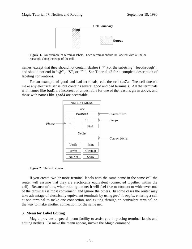
Magic Tutorial #7: Netlists and Routing September 19, 1990
Output
InputCell Boundary
Figure 1. An example of terminal labels. Each terminal should be labeled with a line orrectangle along the edge of the cell.
names, except that they should not contain slashes (‘‘/’’) or the substring ‘‘feedthrough’’,and should not end in ‘‘@’’, ‘‘$’’, or ‘‘ˆ’’. See Tutorial #2 for a complete description oflabeling conventions.
For an example of good and bad terminals, edit the cell tut7a. The cell doesn’tmake any electrical sense, but contains several good and bad terminals. All the terminalswith names like bad1 are incorrect or undesirable for one of the reasons given above, andthose with names like good4 are acceptable.
NETLIST MENU
Label
13
BusBit13
ShowNo Net
CleanupTerms
PrintVerify
Netlist
Find
Current Text
PumpsPlacer
Current Netlist
Figure 2. The netlist menu.
If you create two or more terminal labels with the same name in the same cell therouter will assume that they are electrically equivalent (connected together within thecell). Because of this, when routing the net it will feel free to connect to whichever oneof the terminals is most convenient, and ignore the others. In some cases the router maytake advantage of electrically equivalent terminals by using feed throughs: entering a cellat one terminal to make one connection, and exiting through an equivalent terminal onthe way to make another connection for the same net.
3. Menu for Label Editing
Magic provides a special menu facility to assist you in placing terminal labels andediting netlists. To make the menu appear, invoke the Magic command
- 3 -

Magic Tutorial #7: Netlists and Routing September 19, 1990
iiiiiiiiiiiiiiiiiiiiiiiiiiiiiiiiiiiiiiiiiiiiiiiiiiiiiiiiiiiiiiButton Actioniiiiiiiiiiiiiiiiiiiiiiiiiiiiiiiiiiiiiiiiiiiiiiiiiiiiiiiiiiiiii
Left-click: prompt for more labelsCurrent Text
Right-click: advance to next labeliiiiiiiiiiiiiiiiiiiiiiiiiiiiiiiiiiiiiiiiiiiiiiiiiiiiiiiiiiiiiiLeft-click: place label
PlacerRight-click: change label text positioniiiiiiiiiiiiiiiiiiiiiiiiiiiiiiiiiiiiiiiiiiiiiiiiiiiiiiiiiiiiiiLeft-click: decrement number
PumpsRight-click: increment numberiiiiiiiiiiiiiiiiiiiiiiiiiiiiiiiiiiiiiiiiiiiiiiiiiiiiiiiiiiiiiiSearch under box, highlight labels
Findmatching current textiiiiiiiiiiiiiiiiiiiiiiiiiiiiiiiiiiiiiiiiiiiiiiiiiiiiiiiiiiiiiiLeft-click: prompt for new netlist name
Current NetlistRight-click: use edit cell name as netlist nameiiiiiiiiiiiiiiiiiiiiiiiiiiiiiiiiiiiiiiiiiiiiiiiiiiiiiiiiiiiiiiCheck that wiring matches netlist (same as
Verifytyping :verify command)iiiiiiiiiiiiiiiiiiiiiiiiiiiiiiiiiiiiiiiiiiiiiiiiiiiiiiiiiiiiiiPrint names of all terminals in selected net
Print(same as typing :print command)iiiiiiiiiiiiiiiiiiiiiiiiiiiiiiiiiiiiiiiiiiiiiiiiiiiiiiiiiiiiiiPlace feedback areas on screen to identify all terminals
Termsin current netlist (same as :showterms command)iiiiiiiiiiiiiiiiiiiiiiiiiiiiiiiiiiiiiiiiiiiiiiiiiiiiiiiiiiiiiiCheck current netlist for missing labels and netswith less than two terminals (same as typingCleanup:cleanup command)iiiiiiiiiiiiiiiiiiiiiiiiiiiiiiiiiiiiiiiiiiiiiiiiiiiiiiiiiiiiii
No Net Delete selected net (same as :dnet command)iiiiiiiiiiiiiiiiiiiiiiiiiiiiiiiiiiiiiiiiiiiiiiiiiiiiiiiiiiiiiiHighlight paint connected to material under box
Show(same as typing :shownet command)iiiiiiiiiiiiiiiiiiiiiiiiiiiiiiiiiiiiiiiiiiiiiiiiiiiiiiiiiiiiiic
cccccccccccccccccccccccccccc
ccccccccccccccccccccccccccccc
ccccccccccccccccccccccccccccc
Table I. A summary of all the netlist menu button actions.
:specialopen netlist
A new window will appear in the lower-left corner of the screen, containing several rec-tangular areas on a purple background. Each of the rectangular areas is called a button.Clicking mouse buttons inside the menu buttons will invoke various commands to editlabels and netlists. Figure 2 shows a diagram of the netlist menu and Table I summarizesthe meaning of button clicks in various menu items. The netlist menu can be grown,shrunk, and moved just like any other window; see ‘‘Magic Tutorial #5: Multiple Win-dows’’ for details. It also has its own private set of commands. To see what commandsyou can type in the netlist menu, move the cursor over the menu and type
:help
You shouldn’t need to type commands in the netlist menu very often, since almost every-thing you’ll need to do can be done using the menu. See Section 9 for a description of afew of the commands you can type; the complete set is described in the manual pagemagic(1). One of the best uses for the commands is so that you can define macros forthem and avoid having to go back and forth to the menu; look up the :send command inthe man page to see how to do this. The top half of the menu is for placing labels and thebottom half is for editing netlists. This section describes the label facilities, and Section
- 4 -

Magic Tutorial #7: Netlists and Routing September 19, 1990
4 describes the netlist facilities.
The label menu makes it easy for you to enter lots of labels, particularly when thereare many labels that are the same except for a number, e.g. bus1, bus2, bus3, etc. Thereare four sections to the label menu: the current text, the placer, two pumps, and the Findbutton. To place labels, first click the left mouse button over the current text rectangle.Then type one or more labels on the keyboard, one per line. You can use this mechanismto enter several labels at once. Type return twice to signal the end of the list. At thispoint, the first of the labels you typed will appear in the current text rectangle.
To place a label, position the box over the area you want to label, then click the leftmouse button inside one of the squares of the placer area. A label will be created withthe current text. Where you click in the placer determines where the label text willappear relative to the label box: for example, clicking the left-center square causes thetext to be centered just to the left of the box. You can place many copies of the samelabel by moving the box and clicking the placer area again. You can re-orient the text ofa label by clicking the right mouse button inside the placer area. For example, if youwould like to move a label’s text so that it appears centered above the label, place thebox over the label and right-click the top-center placer square.
If you entered several labels at once, only the first appears in the current text area.However, you can advance to the next label by right-clicking inside the current text area.In this way you can place a long series of labels entirely with the mouse. Try using thismechanism to add labels to tut7a.
The two small buttons underneath the right side of the current text area are calledpumps. To see how these work, enter a label name containing a number into the currenttext area, for example, bus1. When you do this, the ‘‘1’’ appears in the left pump.Right-clicking the pump causes the number to increment, and left-clicking the pumpcauses the number to decrement. This makes it easy for you to enter a series of num-bered signal names. If a name has two numbers in it, the second number will appear inthe second pump, and it can be incremented or decremented too. Try using the pumps toplace a series of numbered names.
The last entry in the label portion of the menu is the Find button. This can be usedto locate a label by searching for a given pattern. If you click the Find button, Magicwill use the current text as a pattern and search the area underneath the box for a labelwhose name contains the pattern. Pattern-matching is done in the same way as in csh,using the special characters ‘‘*’’, ‘‘?’’, ‘‘\’’, ‘‘[’’, and ‘‘]’’. Try this on tut7a: enter‘‘good*’’ into the current text area, place the box around the whole cell, then click on the‘‘Find’’ button. For each of the good labels, a feedback area will be created with whitestripes to highlight the area. The :feedback find command can be used to step throughthe areas, and :feedback clear will erase the feedback information from the screen. The:feedback command has many of the same options as :drc for getting information aboutfeedback areas; see the Magic manual page for details, or type :feedback help for asynopsis of the options.
- 5 -

Magic Tutorial #7: Netlists and Routing September 19, 1990
4. Netlist Editing
After placing terminal labels, the next step is to specify the connections betweenthem; this is called netlist editing. The bottom half of the netlist menu is used for editingnetlists. The first thing you must do is to specify the netlist you want to edit. Do this byclicking in the current netlist box. If you left-click, Magic will prompt you for the netlistname and you can type it at the keyboard. If you right-click, Magic will use the name ofthe edit cell as the current netlist name. In either case, Magic will read the netlist fromdisk if it exists and will create a new netlist if there isn’t currently a netlist file with thegiven name. Netlist files are stored on disk with a ‘‘.net’’ extension, which is added byMagic when it reads and writes files. You can change the current netlist by clicking thecurrent netlist button again. Startup Magic on the cell tut7b, open the netlist menu, andset the current netlist to tut7b. Then expand the subcells in tut7b so that you can seetheir terminals.
iiiiiiiiiiiiiiiiiiiiiiiiiiiiiiiiiiiiiiiiiiiiiiButton ActioniiiiiiiiiiiiiiiiiiiiiiiiiiiiiiiiiiiiiiiiiiiiiiLeft Select net, using nearest terminal to cursor.iiiiiiiiiiiiiiiiiiiiiiiiiiiiiiiiiiiiiiiiiiiiii
Toggle nearest terminal into or out ofRight
current net.iiiiiiiiiiiiiiiiiiiiiiiiiiiiiiiiiiiiiiiiiiiiiiFind nearest terminal, join its net with the
Middlecurrent net.iiiiiiiiiiiiiiiiiiiiiiiiiiiiiiiiiiiiiiiiiiiiiic
ccccccc
cccccccc
cccccccc
Table II. The actions of the mouse buttons when the terminal tool is in use.
Netlist editing is done with the netlist tool. If you haven’t already read ‘‘Tutorial#3: Advanced Painting (Wiring and Plowing)’’, you should read it now, up through Sec-tion 2.1. Tutorial #3 explained how to change the current tool by using the space macroor by typing :tool. Switch tools to the netlist tool (the cursor will appear as a thicksquare).
When the netlist tool is in use the left, right, and middle buttons invoke select, tog-gle, and join operations respectively (see Table II). To see how they work, move the cur-sor over the terminal right4 in the top subcell of tut7b and click the left mouse button(you may have to zoom in a bit to see the labels; terminals are numbered in clockwiseorder: right4 is the fourth terminal from the top on the right side). This causes the netcontaining that terminal to be selected. Three hollow white squares will appear over thelayout, marking the terminals that are supposed to be wired together into right4’s net.Left-click over the left3 terminal in the same subcell to select its net, then select theright4 net again.
The right button is used to toggle terminals into or out of the current net. If youright-click over a terminal that is in the current net, then it is removed from the currentnet. If you right-click over a terminal that isn’t in the current net, it is added to thecurrent net. A single terminal can only be in one net at a time, so if a terminal is alreadyin a net when you toggle it into another net then Magic will remove it from the old net.Toggle the terminal top4 in the bottom cell out of, then back into, the net containingright4. Now toggle left3 in the bottom cell into this net. Magic warns you because ithad to remove left3 from another net in order to add it to right4’s net. Type u to undothis change, then left-click on left3 to make sure it got restored to its old net by the undo.
- 6 -

Magic Tutorial #7: Netlists and Routing September 19, 1990
All of the netlist-editing operations are undo-able.
The middle button is used to merge two nets together. If you middle-click over aterminal, all the terminals in its net are added to the current net. Play around with thethree buttons to edit the netlist tut7b.
Note: the router does not make connections to terminals in the top level cell. Itonly works with terminals in subcells, or sub-subcells, etc. Because of this, the netlisteditor does not permit you to select terminals in the top level cell. If you click over sucha terminal Magic prints an error message and refuses to make the selection.
If you left-click over a terminal that is not currently in a net, Magic creates a newnet automatically. If you didn’t really want to make a new net, you have several choices.Either you can toggle the terminal out of its own net, you can undo the select operation,or you can click the No Net button in the netlist menu (you can do this even while thecursor is in the square shape). The No Net button removes all terminals from the currentnet and destroys the net. It’s a bad idea to leave single-net terminals in the netlist: therouter will treat them as errors.
There are two ways to save netlists on disk; these are similar to the ways you cansave layout cells. If you type
:savenetlist [name]
with the cursor over the netlist menu, the current netlist will be saved on disk in the filename.net. If no name is typed, the name of the current netlist is used. If you type thecommand
:writeall
then Magic will step through all the netlists that have been modified since they were lastwritten, asking you if you’d like them to be written out. If you try to leave Magicwithout saving all the modified netlists, Magic will warn you and give you a chance towrite them out.
If you make changes to a netlist and then decide you don’t want them, you can usethe :flush netlist command to throw away all of the changes and re-read the netlist fromits disk file. If you create netlists using a text editor or some other program, you can use:flush after you’ve modified the netlist file in order to make sure that Magic is using themost up-to-date version.
The Print button in the netlist menu will print out on the text screen the names ofall the terminals in the current net. Try this for some of the nets in tut7b. The officialname of a terminal looks a lot like a Unix file name, consisting of a bunch of fieldsseparated by slashes. Each field except the last is the id of a subcell, and the last field isthe name of the terminal. These hierarchical names provide unique names for each ter-minal, even if the same terminal name is re-used in different cells or if there are multiplecopies of the same cell.
The Verify button will check the paint of the edit cell to be sure it implements theconnections specified in the current netlist. Feedback areas are created to show nets thatare incomplete or nets that are shorted together.
The Terms button will cause Magic to generate a feedback area over each of theterminals in the current netlist, so that you can see which terminals are included in the
- 7 -

Magic Tutorial #7: Netlists and Routing September 19, 1990
netlist. If you type the command :feedback clear in a layout window then the feedbackwill be erased.
The Cleanup button is there as a convenience to help you cleanup your netlists. Ifyou click on it, Magic will scan through the current netlist to make sure it is reasonable.Cleanup looks for two error conditions: terminal names that don’t correspond to anylabels in the design, and nets that don’t have at least two terminals. When it finds eitherof these conditions it prints a message and gives you the chance to either delete theoffending terminal (if you type dterm), delete the offending net (dnet), skip the currentproblem without modifying the netlist and continue looking for other problems (skip), orabort the Cleanup command without making any more changes (abort).
The Show button provides an additional mechanism for displaying the paint in thenet. If you place the box over a piece of paint and click on Show, Magic will highlightall of the paint in the net under the box. This is similar to pointing at the net and typing sthree times to select the net, except that Show doesn’t select the net (it uses a differentmechanism to highlight it), and Show will trace through all cells, expanded or not (theselection mechanism only considers paint in expanded cells). Once you’ve used Show tohighlight a net, the only way to make the highlighting go away is to place the box overempty space and invoke Show again. Show is an old command that pre-dates the selec-tion interface, but we’ve left it in Magic because some people find it useful.
5. Netlist Files
Netlists are stored on disk in ordinary text files. You are welcome to edit those filesby hand or to write programs that generate the netlists automatically. For example, a net-list might be generated by a schematic editor or by a high-level simulator. See themanual page net(5) for a description of netlist file format.
6. Running the Router
Once you’ve created a netlist, it is relatively easy to invoke the router. First, placethe box around the area you’d like Magic to consider for routing. No terminals outsidethis area will be considered, and Magic will not generate any paint more than a few unitsoutside this area (Magic may use the next routing grid line outside the area). Load tut7d,:flush the netlist if you made any changes to it, set the box to the bounding box of thecell, and then invoke the router using the command:
:route
When the command completes, the netlist should be routed. Click the Verify netlist but-ton to make sure the connections were made correctly. Try deleting a piece from one ofthe wires and verify again. Feedback areas should appear to indicate where the routingwas incorrect. Use the :feedback command to step through the areas and, eventually, todelete the feedback (:feedback help gives a synopsis of the command options).
If the router is unable to complete the connections, it will report errors to you.Errors may be reported in several ways. For some errors, such as non-existent terminalnames, messages will be printed. For other errors, cross-hatched feedback areas will becreated. Most of the feedback areas have messages similar to ‘‘Net shifter/bit[0]/phi1:
- 8 -
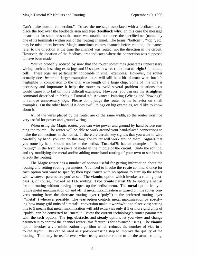
Magic Tutorial #7: Netlists and Routing September 19, 1990
Can’t make bottom connection.’’ To see the message associated with a feedback area,place the box over the feedback area and type :feedback why. In this case the messagemeans that for some reason the router was unable to connect the specified net (named byone of its terminals) within one of the routing channel. The terms ‘‘bottom’’, ‘‘top’’, etc.may be misnomers because Magic sometimes rotates channels before routing: the namesrefer to the direction at the time the channel was routed, not the direction in the circuit.However, the location of the feedback area indicates where the connection was supposedto have been made.
You’ve probably noticed by now that the router sometimes generates unnecessarywiring, such as inserting extra jogs and U-shapes in wires (look next to right3 in the topcell). These jogs are particularly noticeable in small examples. However, the routeractually does better on larger examples: there will still be a bit of extra wire, but it’snegligible in comparison to the total wire length on a large chip. Some of this wire isnecessary and important: it helps the router to avoid several problem situations thatwould cause it to fail on more difficult examples. However, you can use the straightencommand described in ‘‘Magic Tutorial #3: Advanced Painting (Wiring and Plowing)’’to remove unnecessary jogs. Please don’t judge the router by its behavior on smallexamples. On the other hand, if it does awful things on big examples, we’d like to knowabout it.
All of the wires placed by the router are of the same width, so the router won’t bevery useful for power and ground wiring.
When using the Magic router, you can wire power and ground by hand before run-ning the router. The router will be able to work around your hand-placed connections tomake the connections in the netlist. If there are certain key signals that you want to wirecarefully by hand, you can do this too; the router will work around them. Signals thatyou route by hand should not be in the netlist. Tutorial7b has an example of ‘‘handrouting’’ in the form of a piece of metal in the middle of the circuit. Undo the routing,and try modifying the metal and/or adding more hand routing of your own to see how itaffects the routing.
The Magic router has a number of options useful for getting information about therouting and setting routing parameters. You need to invoke the route command once foreach option you want to specify; then type :route with no options to start up the routerwith whatever parameters you’ve set. The viamin, option which invokes a routing post-pass is, of course, invoked AFTER routing. Type :route netlist file to specify a netlistfor the routing without having to open up the netlist menu. The metal option lets youtoggle metal maximization on and off; if metal maximization is turned on, the router con-verts routing from the alternate routing layer (‘‘poly’’) to the preferred routing layer(‘‘metal’’) wherever possible. The vias option controls metal maximization by specify-ing how many grid units of ‘‘metal’’ conversion make it worthwhile to place vias; settingthis to 5 means that metal maximization will add extra vias only if 5 or more grid units of‘‘poly’’ can be converted to ‘‘metal’’. View the current technology’s router parameterswith the tech option. The jog, obstacle, and steady options let you view and changeparameters to control the channel router (this feature is for advanced users). The viaminoption invokes a via minimization algorithm which reduces the number of vias in arouted layout. This can be used as a post-processing step to improve the quality of therouting. This may be useful even when using another router to do the actual routing.
- 9 -

Magic Tutorial #7: Netlists and Routing September 19, 1990
Finally, show all parameter values with the settings option. The options and their actionsare summarized in Table III.
iiiiiiiiiiiiiiiiiiiiiiiiiiiiiiiiiiiiiiiiiiiiiiiiiiiiiiiiiOption Actioniiiiiiiiiiiiiiiiiiiiiiiiiiiiiiiiiiiiiiiiiiiiiiiiiiiiiiiiiend Print the channel router end constantend real Set the channel router end constantiiiiiiiiiiiiiiiiiiiiiiiiiiiiiiiiiiiiiiiiiiiiiiiiiiiiiiiiihelp Print a summary of the router optionsiiiiiiiiiiiiiiiiiiiiiiiiiiiiiiiiiiiiiiiiiiiiiiiiiiiiiiiiijog Print the channel router minimum jog lengthjog int Set the minimum jog length, measured in grid unitsiiiiiiiiiiiiiiiiiiiiiiiiiiiiiiiiiiiiiiiiiiiiiiiiiiiiiiiiimetal Toggle metal maximization on or offiiiiiiiiiiiiiiiiiiiiiiiiiiiiiiiiiiiiiiiiiiiiiiiiiiiiiiiiinetlist Print the name of the current net listnetlist file Set the current net listiiiiiiiiiiiiiiiiiiiiiiiiiiiiiiiiiiiiiiiiiiiiiiiiiiiiiiiiiobstacle Print the channel router obstacle constantobstacle real Set the obstacle constantiiiiiiiiiiiiiiiiiiiiiiiiiiiiiiiiiiiiiiiiiiiiiiiiiiiiiiiiisettings Print a list of all router parametersiiiiiiiiiiiiiiiiiiiiiiiiiiiiiiiiiiiiiiiiiiiiiiiiiiiiiiiiisteady Print the channel router steady net constantsteady int Set the steady net constant, measured in grid unitsiiiiiiiiiiiiiiiiiiiiiiiiiiiiiiiiiiiiiiiiiiiiiiiiiiiiiiiiitech Print router technology informationiiiiiiiiiiiiiiiiiiiiiiiiiiiiiiiiiiiiiiiiiiiiiiiiiiiiiiiiivias Print the metal maximization via limitvias int Set the via limitiiiiiiiiiiiiiiiiiiiiiiiiiiiiiiiiiiiiiiiiiiiiiiiiiiiiiiiiiviamin Minimize vias in a routed layout.iiiiiiiiiiiiiiiiiiiiiiiiiiiiiiiiiiiiiiiiiiiiiiiiiiiiiiiiiccccccccccccccccccccccc
ccccccccccccccccccccccc
ccccccccccccccccccccccc
Table III. A summary of all of Magic router options.
7. How the Router Works
In order to make the router produce the best possible results, it helps to know a littlebit about how it works. The router runs in three stages, called channel definition, globalrouting, and channel routing. In the channel definition phase, Magic divides the area ofthe edit cell into rectangular routing areas called channels. The channels cover all thespace under the box except the areas occupied by subcells. All of Magic’s routing goesin the channel areas, except that stems (Section 8.2) may extend over subcells.
To see the channel structure that Magic chose, place the box in tut7d as if you weregoing to route, then type the command
:channel
in the layout window. Magic will compute the channel structure and display it on thescreen as a collection of feedback areas. The channel structure is displayed as white rec-tangles. Type :feedback clear when you’re through looking at them.
The second phase of routing is global routing. In the global routing phase, Magicconsiders each net in turn and chooses the sequence of channels the net must passthrough in order to connect its terminals. The crossing points (places where the netcrosses from one channel to another) are chosen at this point, but not the exact paththrough each channel.
- 10 -

Magic Tutorial #7: Netlists and Routing September 19, 1990
In the third phase, each channel is considered separately. All the nets passingthrough that channel are examined at once, and the exact path of each net is decided.Once the routing paths have been determined, paint is added to the edit cell to implementthe routing.
The router is grid-based: all wires are placed on a uniform grid. For the standardnMOS process the grid spacing is 7 units, and for the standard SCMOS process it is 8units. If you type :grid 8 after routing tut7b, you’ll see that all of the routing lines upwith its lower and left sides on grid lines. Fortunately, you don’t have to make your cellterminals line up on even grid boundaries. During the routing Magic generates stems thatconnect your terminals up to grid lines at the edges of channels. Notice that there’s spaceleft by Magic between the subcells and the channels; this space is used by the stem gen-erator.
8. What to do When the Router Fails
Don’t be surprised if the router is unable to make all the connections the first timeyou try it on a large circuit. Unless you have extra routing space in your chip, you mayhave to make slight re-arrangements to help the router out. The paragraphs belowdescribe things you can do to make life easier for the router. This section is not very welldeveloped, so we’d like to hear about techniques you use to improve routability. If youdiscover new techniques, send us mail and we’ll add them to this section.
8.1. Channel Structure
One of the first things to check when the router fails is the channel structure. Ifusing the Magic router, type :channel to look at the channels. One common mistake isto have some of the desired routing area covered by subcells; Magic only runs wireswhere there are no subcells. Check to be sure that there are channels everywhere thatyou’re expecting wires to run. If you place cells too close together, there may not beenough room to have a channel between the cells; when this happens Magic will routewilly-nilly across the tops of cells to bring terminals out to channels, and will probablygenerate shorts or design-rule violations. To solve the problem, move the cells fartherapart. If there are many skinny channels, it will be difficult for the router to producegood routing. Try to re-arrange the cell structure to line up edges of nearby cells so thatthere are as few channels as possible and they are as large as possible (before doing thisyou’ll probably want to get rid of the existing routing by undo-ing or by flushing the editcell).
8.2. Stems
Another problem has to do with the stem generator. Stems are the pieces of wiringthat connect terminals up to grid points on the edges of channels. The current stem gen-eration code doesn’t know about connectivity or design rules. It simply finds the nearestrouting grid point and wires out to that point, without considering any other terminals. Ifa terminal is not on the edge of the cell, the stem runs straight across the cell to thenearest channel, without any consideration for other material in the cell. If two terminalsare too close together, Magic may decide to route them both to the same grid point.When this happens, you have two choices. Either you can move the cell so that the
- 11 -

Magic Tutorial #7: Netlists and Routing September 19, 1990
terminals have different nearest grid points (for example, you can line its terminals upwith the grid lines), or if this doesn’t work you’ll have to modify the cell to make the ter-minals farther apart.
The place where stems cause the most trouble is in PLAs, many of which have beenoptimized to space the outputs as closely together as possible. In some cases the outputsare closer together than the routing grid, which is an impossible situation for the stemgenerator. In this case, we think the best approach is to change the PLA templates tospace the outputs farther apart. Either space them exactly the same as the router grid (inwhich case you can line the PLAs up before routing so the terminals are already on thegrid), or space the outputs at least 1.5 grid units apart so the stem generator won’t havetroubles. Having tightly-spaced PLA outputs is false economy: it makes it more difficultto design the PLAs and results in awful routing problems. Even if Magic could river-route out from tightly-spaced terminals to grid lines (which it can’t), it would require N2
space to route out N lines; it takes less area to stretch the PLA.
8.3. Obstacles
The router tends to have special difficulties with obstacles running along the edgesof channels. When you’ve placed a power wire or other hand-routing along the edge of achannel, the channel router will often run material under your wiring in the other routinglayer, thereby blocking both routing layers and making it impossible to complete therouting. Where this occurs, you can increase the chances of successful routing by mov-ing the hand-routing away from the channel edges. It’s especially important to keephand-routing away from terminals. The stem generator will not pay any attention tohand-routing when it generates stems (it just makes a bee-line for the nearest grid point),so it may accidentally short a terminal to nearby hand-routing.
Figure 3. When placing hand routing, it is best to place wires with their left and bottomedges along grid lines, and contacts centered on the wires. In this fashion, the hand routingwill block as few routing grid lines as possible.
- 12 -

Magic Tutorial #7: Netlists and Routing September 19, 1990
When placing hand-routing, you can get better routing results by following theadvice illustrated in Figure 3. First, display the routing grid. For example, if the router isusing a 8-unit grid (which is true for the standard SCMOS technology), type :grid 8.Then place all your hand routing with its left and bottom edges along the grid lines.Because of the way the routing tools work, this approach results in the least possibleamount of lost routing space.
9. More Netlist Commands
In addition to the netlist menu buttons and commands described in Section 4, thereare a number of other netlist commands you can invoke by typing in the netlist window.Many of these commands are textual equivalents of the menu buttons. However, theyallow you to deal with terminals by typing the hierarchical name of the terminal ratherthan by pointing to it. If you don’t know where a terminal is, or if you have deleted alabel from your design so that there’s nothing to point to, you’ll have to use the textualcommands. Commands that don’t just duplicate menu buttons are described below; seethe magic(1) manual page for details on the others.
The netlist command
:extract
will generate a net from existing wiring. It looks under the box for paint, then traces outall the material in the edit cell that is connected electrically to that paint. Wherever thematerial touches subcells it looks for terminals in the subcells, and all the terminals itfinds are placed into a new net. Warning: there is also an extract command for layoutwindows, and it is totally different from the extract command in netlist windows. Makesure you’ve got the cursor over the netlist window when you invoke this command!
The netlist editor provides two commands for ripping up existing routing (or othermaterial). They are
:ripup:ripup netlist
The first command starts by finding any paint in the edit cell that lies underneath the box.It then works outward from that paint to find all paint in the edit cell that is electricallyconnected to the starting paint. All of this paint is erased. (:ripup isn’t really necessary,since the same effect can be achieved by selecting all the paint in the net and deleting theselection; it’s a hangover from olden days when there was no selection). The secondform of the command, :ripup netlist, is similar to the first except that it starts from eachof the terminals in the current netlist instead of the box. Any paint in the edit cell that iselectrically connected to a terminal is erased. The :ripup netlist command may be use-ful to ripup existing routing before rerouting.
The command
:trace [name]
provides an additional facility for examining router feedback. It highlights all paint con-nected to each terminal in the net containing name, much as the Show menu button doesfor paint connected to anything under the box. The net to be highlighted may be
- 13 -

Magic Tutorial #7: Netlists and Routing September 19, 1990
specified by naming one of its terminals, for example, :trace shifter/bit[0]/phi1. Use thetrace command in conjunction with the nets specified in router feedback to see the par-tially completed wiring for a net. Where no net is specified, the :trace commandhighlights the currently selected net.
- 14 -

Magic Tutorial #8: Circuit Extraction
Walter Scott(some updates by other folks, too)
Special Studies ProgramLawrence Livermore National Laboratory
PO Box 808, L-270Livermore, CA [email protected]
This tutorial corresponds to Magic version 6.
Tutorials to read first:
Magic Tutorial #1: Getting StartedMagic Tutorial #2: Basic Painting and SelectionMagic Tutorial #4: Cell Hierarchies
Commands introduced in this tutorial:
:extract
Macros introduced in this tutorial:
none
Programs introduced in this tutorial:
ext2sim
ext2spice
extcheck
Changes since Magic version 4:
New form of :extract unique
Path length extraction with :extract length
Accurate resistance extraction with :extresis
Extraction of well connectivity and substrate nodes
Checking for global net connectedness in ext2sim (1)
New programs: ext2spice (1) and extcheck (1)
- 1 -
Magic Tutorial #8: Circuit Extraction September 19, 1990
1. Introduction
This tutorial covers the use of Magic’s circuit extractor. The extractor computesfrom the layout the information needed to run simulation tools such as crystal (1) andesim (1). This information includes the sizes and shapes of transistors, and the connec-tivity, resistance, and parasitic capacitance of nodes. Both capacitance to substrate andseveral kinds of internodal coupling capacitances are extracted.
Magic’s extractor is both incremental and hierarchical: only part of the entire layoutmust be re-extracted after each change, and the structure of the extracted circuit parallelsthe structure of the layout being extracted. The extractor produces a separate .ext file foreach .mag file in a hierarchical design. This is in contrast to previous extractors, such asMextra, which produces a single .sim file that represents the flattened (fully-instantiated)layout.
Sections 2 through 4 introduce Magic’s :extract command and some of its moreadvanced features. Section 5 describes what information actually gets extracted, anddiscusses limitations and inaccuracies. Section 6 talks about extraction styles. Althoughthe hierarchical ext (5) format fully describes the circuit implemented by a layout, veryfew tools currently accept it. It is normally necessary to flatten the extracted circuit usingone of the programs discussed in Section 7, such as ext2sim (1), ext2spice (1), orextcheck (1).
2. Basic Extraction
You can use Magic’s extractor in one of several ways. Normally it is not necessaryto extract all cells in a layout. To extract only those cells that have changed since theywere extracted, use:
:load root:extract
The extractor looks for a .ext file for every cell in the tree that descends from the cellroot. The .ext file is searched for in the same directory that contains the cell’s .mag file.Any cells that have been modified since they were last extracted, and all of their parents,are re-extracted. Cells having no .ext files are also re-extracted.
To try out the extractor on an example, copy all the tut8x cells to your current direc-tory with the following shell commands:
cp ˜cad/lib/magic/tutorial/tut8*.mag .
Start magic on the cell tut8a and type :extract. Magic will print the name of each cell(tut8a, tut8b, tut8c, and tut8d) as it is extracted. Now type :extract a second time.This time nothing gets printed, since Magic didn’t have to re-extract any cells. Nowdelete the piece of poly labelled ‘‘delete me’’ and type :extract again. This time, onlythe cell tut8a is extracted as it is the only one that changed. If you make a change to celltut8b (do it) and then extract again, both tut8b and tut8a will be re-extracted, sincetut8a is the parent of tut8b.
To force all cells in the subtree rooted at cell root to be re-extracted, use:extract all:
- 2 -

Magic Tutorial #8: Circuit Extraction September 19, 1990
:load root:extract all
Try this also on tut8a.
You can also use the :extract command to extract a single cell as follows:
:extract cell name
will extract just the selected (current) cell, and place the output in the file name. Selectthe cell tut8b (tut8b_0) and type :extract cell differentFile to try this out. After thiscommand, the file differentFile.ext will contain the extracted circuit for the cell tut8b.The children of tut8b (in this case, the single cell tut8d) will not be re-extracted by thiscommand. If more than one cell is selected, the upper-leftmost one is extracted.
You should be careful about using :extract cell, since even though you may onlymake a change to a child cell, all of its parents may have to be re-extracted. To re-extractall of the parents of the selected cell, you may use
:extract parents
Try this out with tut8b still selected. Magic will extract only the cell tut8a, since it isthe only one that uses the cell tut8b. To see what cells would be extracted by :extractparents without actually extracting them, use
:extract showparents
Try this command as well.
3. Feedback: Errors and Warnings
When the extractor encounters problems, it leaves feedback in the form of stippledwhite rectangular areas on the screen. Each area covers the portion of the layout thatcaused the error. Each area also has an error message associated with it, which you cansee by using the :feedback command. Type :feedback help while in Magic for assis-tance in using the :feedback command.
The extractor will always report extraction errors. These are problems in the layoutthat may cause the output of the extractor to be incorrect. The layout should be fixed toeliminate extraction errors before attempting to simulate the circuit; otherwise, the resultsof the simulation may not reflect reality.
Extraction errors can come from violations of transistor rules. There are two rulesabout the formation of transistors: no transistor can be formed, and none can be des-troyed, as a result of cell overlaps. For example, it is illegal to have poly in one celloverlap diffusion in another cell, as that would form a transistor in the parent where nonewas present in either child. It is also illegal to have a buried contact in one cell overlap atransistor in another, as this would destroy the transistor. Violating these transistor ruleswill cause design-rule violations as well as extraction errors. These errors only relate tocircuit extraction: the fabricated circuit may still work; it just won’t be extractedcorrectly.
In general, it is an error for material of two types on the same plane to overlap orabut if they don’t connect to each other. For example, in CMOS it is illegal for p-diffusion and n-diffusion to overlap or abut.
- 3 -

Magic Tutorial #8: Circuit Extraction September 19, 1990
In addition to errors, the extractor can give warnings. If only warnings are present,the extracted circuit can still be simulated. By default, only some types of warnings arereported and displayed as feedback. To cause all warnings to be displayed, use
:extract warn all
The command
:extract warn warning
may be used to enable specific warnings selectively; see below. To cause no warnings tobe displayed, or to disable display of a particular warning, use respectively
:extract warn no all or:extract warn no warning
Three different kinds of warnings are generated. The dup warning checks to seewhether you have two electrically unconnected nodes in the same cell labelled with thesame name. If so, you are warned because the two unconnected nodes will appear to beconnected in the resulting .ext file, which means that the extracted circuit would notrepresent the actual layout. This is bad if you’re simulating the circuit to see if it willwork correctly: the simulator will think the two nodes are connected, but since there’s nophysical wire between them, the electrons won’t! When two unconnected nodes sharethe same label (name), the extractor leaves feedback squares over each instance of theshared name.
It’s an excellent idea to avoid labelling two unconnected nodes with the same namewithin a cell. Instead, use the "correct" name for one of the nodes, and some mnemonicbut textually distinct name for the other nodes. For example, in a cell with multiplepower rails, you might use Vdd! for one of the rails, and names like Vdd#1 for the oth-ers. As an example, load the cell tut8e. If the two nodes are connected in a higher-levelcell they will eventually be merged when the extracted circuit is flattened. If you want tosimulate a cell out of context, but still want the higher-level nodes to be hooked up, youcan always create a dummy parent cell that hooks them together, either with wire or byusing the same name for pieces of paint that lie over the terminals to be connected; seethe cell tut8f for an example of this latter technique.
You can use the command
:extract unique
as an automatic means of labelling nodes in the manner described above. Run this com-mand on the cell tut8g. A second version of this command is provided for compatibilitywith previous versions of Magic. Running
:extract unique #
will only append a unique numeric suffix to labels that end with a ‘‘#’’. Any other dupli-cate nodenames that also don’t end in a ‘‘!’’ (the global nodename suffix as described inSection 5) are flagged by feedback.
A second type of warning, fets, checks to see whether any transistors have fewerdiffusion terminals than the minimum for their types. For example, the transistor type‘‘dfet’’ is defined in the nmos technology file as requiring two diffusion terminals: a
- 4 -

Magic Tutorial #8: Circuit Extraction September 19, 1990
source and a drain. If a capacitor with only one diffusion terminal is desired in this tech-nology, the type dcap should be used instead. The fets warning is a consistency checkfor transistors whose diffusion terminals have been accidentally shorted together, or fortransistors with insufficiently many diffusion terminals.
The third warning, labels, is generated if you violate the following guideline forplacement of labels: Whenever geometry from two subcells abuts or overlaps, it’s a goodidea to make sure that there is a label attached to the geometry in each subcell in the areaof the overlap or along the line of abutment. Following this guideline isn’t necessary forthe extractor to work, but it will result in noticeably faster extraction.
By default, the dup and fets warnings are enabled, and the labels warning is dis-abled.
Load the cell tut8h, expand all its children (tut8i and tut8j), and enable all extrac-tor warnings with :extract warn all. Now extract tut8h and all of its children with:extract, and examine the feedback for examples of fatal errors and warnings.
4. Advanced Circuit Extraction
4.1. Lengths
The Magic extractor has a rudimentary ability to compute wire lengths betweenspecific named points in a circuit. This feature is intended for use with technologieswhere the wire length between two points is more important than the total capacitance onthe net; this may occur, for example, when extracting circuits with very long wires beingdriven at high speeds (e.g., bipolar circuits). Currently, you must indicate to Magicwhich pairs of points are to have distances computed. You do this by providing two lists:one of drivers and one of receivers. The extractor computes the distance between eachdriver and each receiver that it is connected to.
Load the cell tut8k. There are five labels: two are drivers (driver1 and driver2)and three are receivers (receiverA, receiverB, and receiverC). Type the commands:
:extract length driver driver1 driver2:extract length receiver receiverA receiverB receiverC
Now enable extraction of lengths with :extract do length and then extract the cell(:extract). If you examine tut8k.ext, you will see several distance lines, correspondingto the driver-receiver distances described above. These distances are through the center-lines of wires connecting the two labels; where multiple paths exist, the shortest is used.
Normally the driver and receiver tables will be built by using :source to read a fileof :extract length driver and :extract length receiver commands. Once these tablesare created in Magic, they remain until you leave Magic or type the command
:extract length clear
which wipes out both tables.
Because extraction of wire lengths is not performed hierarchically, it should only bedone in the root cell of a design. Also, because it’s not hierarchical, it can take a longtime for long, complex wires such as power and ground nets. This feature is still experi-mental and subject to change.
- 5 -

Magic Tutorial #8: Circuit Extraction September 19, 1990
4.2. Resistance
Magic provides for more accurate resistance extraction using the :extresis com-mand. :extresis provides a detailed resistance/capacitance description for nets whereparasitic resistance is likely to significantly affect circuit timing.
4.2.1. Tutorial Introduction
To try out the resistance extractor, load in the cell tut8r. Extract it using :extract,pause magic, and run ext2sim on the cell with the command
ext2sim tut8r
This should produce tut8r.sim, tut8r.nodes, and tut8r.al. Restart magic and type
:extresis tolerance 10:extresis
This will extract interconnect resistances for any net where the interconnect delay is atleast one-tenth of the transistor delay. Magic should give the messages:
:extresis tolerance 10:extresisAdding net2; Tnew = 0.428038ns,Told = 0.3798nsAdding net1; Tnew = 0.529005ns,Told = 0.4122nsTotal Nets: 7Nets extracted: 2 (0.285714)Nets output: 2 (0.285714)
These may vary slightly depending on your technology parameters. The Adding [net]lines describe which networks for which magic produced resistor networks. Tnew is theestimated delay on the net including the resistor parasitics, while Told is the delaywithout parasitics. The next line describes where magic thinks the slowest node in the netis. The final 3 lines give a brief summary of the total number of nets, the nets requiringextraction, and the number for which resistors were added to the output.
Running the resistance extractor also produced the file cell.res.ext. To produce a.sim file containing resistors, quit magic and type:
cat tut8r.ext tut8r.res.ext >tut8r.2.extext2sim -R -t! -t# tut8r.2
Comparing the two files, tut8r.sim and tut8r.2.sim, shows that the latter has the nodesnet1 and net2 split into several parts, with resistors added to connect the new nodestogether.
4.2.2. General Notes on using the resistance extractor
To use :extresis, the circuit must first be extracted using :extract and flattenedusing ext2sim. When ext2sim is run, do not use the -t# and -t! flags (i.e. don’t trim thetrailing "#" and "!" characters) or the -R flag because :extresis needs the .sim and .extnames to correspond exactly, and it needs the lumped resistance values that the extractorproduces. Also, do not delete or rename the .nodes file; :extresis needs this to run. Oncethe .sim and .nodes files have been produced, type the command :extresis while running
- 6 -

Magic Tutorial #8: Circuit Extraction September 19, 1990
magic on the root cell. As the resistance extractor runs, it will identify which nets (ifany) for which it is producing RC networks, and will identify what it thinks is the"slowest" point in the network. When it completes, it will print a brief summary of howmany nets it extracted and how many required supplemental networks. The resistancenetworks are placed in the file root.res.ext. To produce a .sim file with the supplementalresistors, type cat root.ext root.res.ext >newname.ext, and then rerun ext2sim on thenew file. During this second ext2sim run, the -t flag may be used.
Like extraction of wire lengths, resistance extraction is not performed hierarchi-cally; it should only be done in the root cell of a design and can take a long time for com-plex wires.
4.2.3. Options, Features, Caveats and Bugs
The following is a list of command line options and the arguments that they take.
tolerance [value] - This controls how large the resistance in a network must bebefore it is added to the output description. value is defined as the minimum ratio oftransistor resistance to interconnect resistance that requires a resistance network. Thedefault value is 1; values less than 1 will cause fewer resistors to be output and will makethe program run faster, while values greater than 1 will produce more a larger, moreaccurate description but will run slower.
all - Causes all nets in the circuit to be extracted; no comparison between transistorsize and lumped resistance is performed. This option is not recommended for largedesigns.
simplify [on/off] - Turns on/off the resistance network simplification routines.Magic normally simplifies the resistance network it extracts by removing small resistors;specifying this flag turns this feature off.
extout [on/off] - Turns on and off the writing of the root.res.ext file. The defaultvalue is on.
lumped [on/off] - Turns on the writing of root.res.lump. This file contains anupdated value of the lumped resistance for each net that :extresis extracts.
silent [on/off] - This option suppresses printing of the name and location of nets forwhich resistors are produced.
skip mask - Specifies a list of layers that the resistance extractor is to ignore.
help - Print brief list of options.
Attribute labels may also be used to specify certain extractor options. For a descrip-tion of attributes and how they work, see tutorial 2. Following is a description of:extresis attributes.
res:skip@ - Causes this net to be skipped. This is useful for avoiding extraction ofpower supplies or other DC signals that are not labeled Vdd or GND.
res:force@ - Forces extraction of this net regardless of its lumped resistance value.Nets with both skip and force labels attached will cause the extractor to complain.
res:min=[value]@ - Sets the smallest resistor size for this net. The default value isthe resistance of the largest driving transistor divided by the tolerance described above.
- 7 -
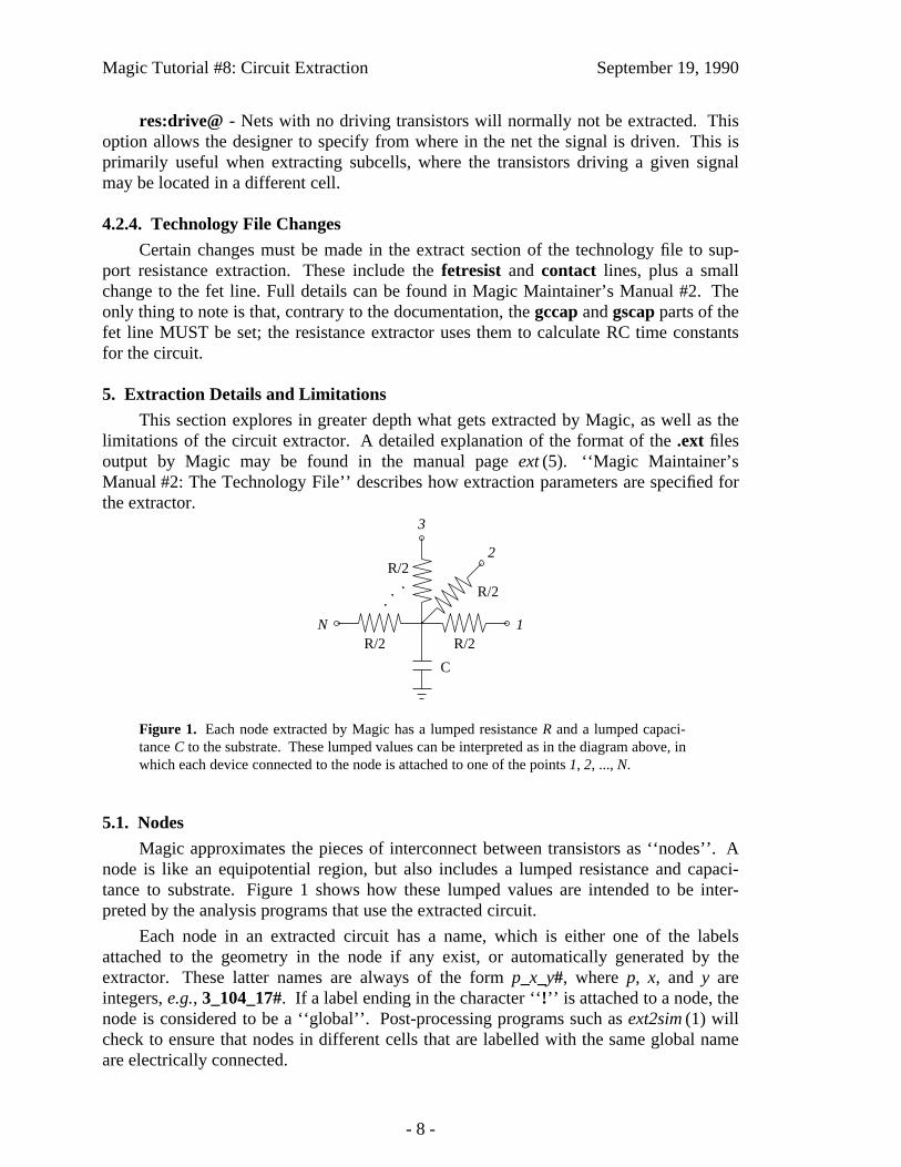
Magic Tutorial #8: Circuit Extraction September 19, 1990
res:drive@ - Nets with no driving transistors will normally not be extracted. Thisoption allows the designer to specify from where in the net the signal is driven. This isprimarily useful when extracting subcells, where the transistors driving a given signalmay be located in a different cell.
4.2.4. Technology File Changes
Certain changes must be made in the extract section of the technology file to sup-port resistance extraction. These include the fetresist and contact lines, plus a smallchange to the fet line. Full details can be found in Magic Maintainer’s Manual #2. Theonly thing to note is that, contrary to the documentation, the gccap and gscap parts of thefet line MUST be set; the resistance extractor uses them to calculate RC time constantsfor the circuit.
5. Extraction Details and Limitations
This section explores in greater depth what gets extracted by Magic, as well as thelimitations of the circuit extractor. A detailed explanation of the format of the .ext filesoutput by Magic may be found in the manual page ext (5). ‘‘Magic Maintainer’sManual #2: The Technology File’’ describes how extraction parameters are specified forthe extractor.
1
2
3
N
C
R/2 R/2
R/2
R/2
Figure 1. Each node extracted by Magic has a lumped resistance R and a lumped capaci-tance C to the substrate. These lumped values can be interpreted as in the diagram above, inwhich each device connected to the node is attached to one of the points 1, 2, ..., N.
5.1. Nodes
Magic approximates the pieces of interconnect between transistors as ‘‘nodes’’. Anode is like an equipotential region, but also includes a lumped resistance and capaci-tance to substrate. Figure 1 shows how these lumped values are intended to be inter-preted by the analysis programs that use the extracted circuit.
Each node in an extracted circuit has a name, which is either one of the labelsattached to the geometry in the node if any exist, or automatically generated by theextractor. These latter names are always of the form p_x_y#, where p, x, and y areintegers, e.g., 3_104_17#. If a label ending in the character ‘‘!’’ is attached to a node, thenode is considered to be a ‘‘global’’. Post-processing programs such as ext2sim (1) willcheck to ensure that nodes in different cells that are labelled with the same global nameare electrically connected.
- 8 -

Magic Tutorial #8: Circuit Extraction September 19, 1990
Nodes may have attributes attached to them as well as names. Node attributes arelabels ending in the special character ‘‘@’’, and provide a mechanism for passing infor-mation to analysis programs such as crystal (1). The man page ext (5) provides additionalinformation about node attributes.
5.2. Resistance
Magic extracts a lumped resistance for each node, rather than a point-to-point resis-tance between each pair of devices connected to that node. The result is that all suchpoint-to-point resistances are approximated by the worst-case resistance between any twopoints in that node.
By default, node resistances are approximated rather than computed exactly. For anode comprised entirely of a single type of material, Magic will compute the node’s totalperimeter and area. It then solves a quadratic equation to find the width and height of asimple rectangle with this same perimeter and area, and approximates the resistance ofthe node as the resistance of this ‘‘equivalent’’ rectangle. The resistance is always takenin the longer dimension of the rectangle. When a node contains more than a single typeof material, Magic computes an equivalent rectangle for each type, and then sums theresistances as though the rectangles were laid end-to-end.
This approximation for resistance does not take into account any branching, so itcan be significantly in error for nodes that have side branches. Figure 2 gives an exam-ple. For global signal trees such as clocks or power, Magic’s estimate of resistance willlikely be several times higher than the actual resistance between two points.
(a) (b)
2 211
Figure 2. Magic approximates the resistance of a node by assuming that it is a simple wire.The length and width of the wire are estimated from the node’s perimeter and area. (a) Fornon-branching nodes, this approximation is a good one. (b) The computed resistance forthis node is the same as for (a) because the side branches are counted, yet the actual resis-tance between points 1 and 2 is significantly less than in (a).
The approximated resistance also does not lend itself well to hierarchical adjust-ments, as does capacitance. To allow programs like ext2sim to incorporate hierarchicaladjustments into a resistance approximation, each node in the .ext file also contains a per-imeter and area for each ‘‘resistance class’’ that was defined in the technology file (see‘‘Maintainer’s Manual #2: The Technology File,’’ and ext (5)). When flattening a circuit,ext2sim uses this information along with adjustments to perimeter and area to producethe value it actually uses for node resistance.
- 9 -

Magic Tutorial #8: Circuit Extraction September 19, 1990
If you wish to disable the extraction of resistances and node perimeters and areas,use the command
:extract no resistance
which will cause all node resistances, perimeters, and areas in the .ext file to be zero. Tore-enable extraction of resistance, use the command
:extract do resistance.
Sometimes it’s important that resistances be computed more accurately than is pos-sible using the lumped approximation above. Magic’s :extresist command does this bycomputing explicit two-terminal resistors and modifying the circuit network to includethem so it reflects more exactly the topology of the layout. See the section on AdvancedExtraction for more details on explicit resistance extraction with :extresist.
diff-space perim
diff-buried perimburied
diffusion
Figure 3. Each type of edge has capacitance to substrate per unit length. Here, thediffusion-space perimeter of 13 units has one value per unit length, and the diffusion-buriedperimeter of 3 units another. In addition, each type of material has capacitance per unitarea.
5.3. Capacitance
Capacitance to substrate comes from two different sources. Each type of materialhas a capacitance to substrate per unit area. Each type of edge (i.e, each pair of types)has a capacitance to substrate per unit length. See Figure 3. The computation of capaci-tance may be disabled with
:extract no capacitance
which causes all substrate capacitance values in the .ext file to be zero. It may be re-enabled with
:extract do capacitance.
Internodal capacitance comes from three sources, as shown in Figure 4. Whenmaterials of two different types overlap, the capacitance to substrate of the one on top (asdetermined by the technology) is replaced by an internodal capacitance to the one on thebottom. Its computation may be disabled with
- 10 -
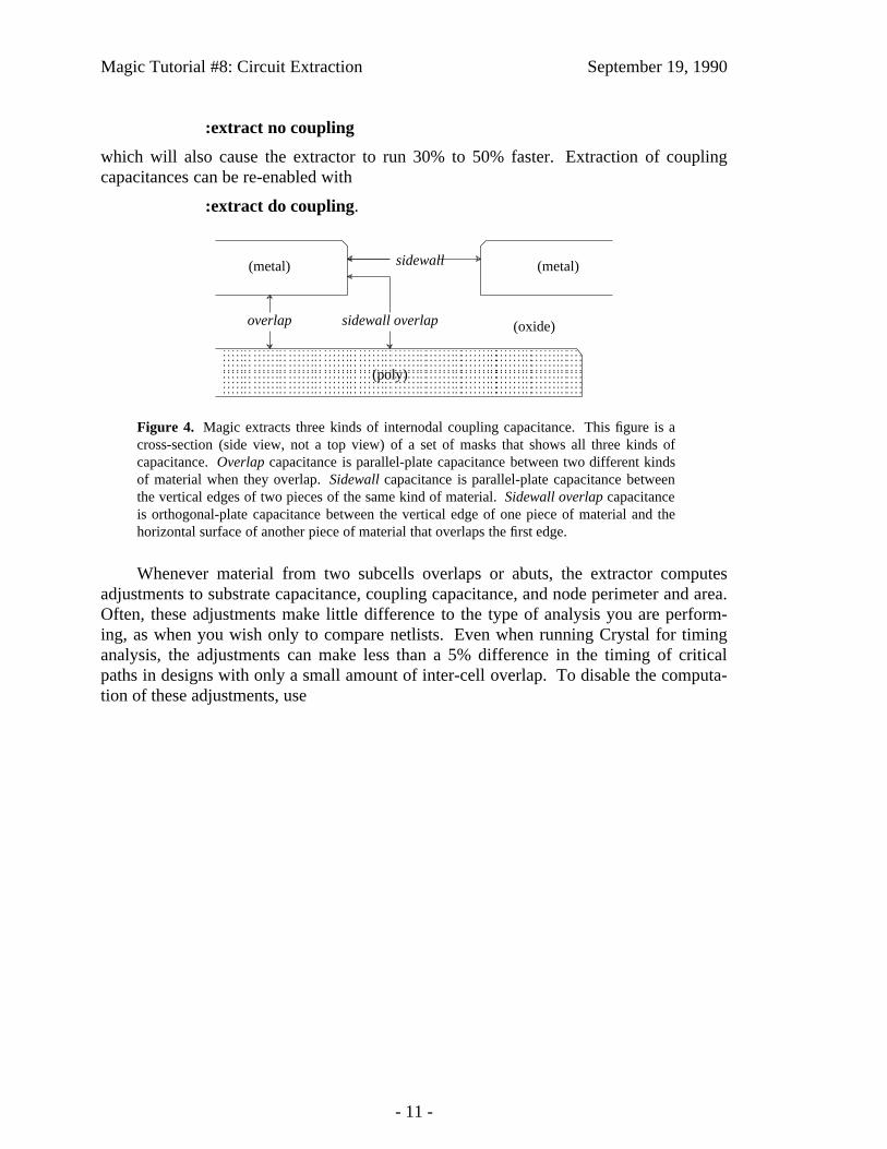
Magic Tutorial #8: Circuit Extraction September 19, 1990
:extract no coupling
which will also cause the extractor to run 30% to 50% faster. Extraction of couplingcapacitances can be re-enabled with
:extract do coupling.
sidewall
sidewall overlapoverlap (oxide)
(poly)
(metal)(metal)
Figure 4. Magic extracts three kinds of internodal coupling capacitance. This figure is across-section (side view, not a top view) of a set of masks that shows all three kinds ofcapacitance. Overlap capacitance is parallel-plate capacitance between two different kindsof material when they overlap. Sidewall capacitance is parallel-plate capacitance betweenthe vertical edges of two pieces of the same kind of material. Sidewall overlap capacitanceis orthogonal-plate capacitance between the vertical edge of one piece of material and thehorizontal surface of another piece of material that overlaps the first edge.
Whenever material from two subcells overlaps or abuts, the extractor computesadjustments to substrate capacitance, coupling capacitance, and node perimeter and area.Often, these adjustments make little difference to the type of analysis you are perform-ing, as when you wish only to compare netlists. Even when running Crystal for timinganalysis, the adjustments can make less than a 5% difference in the timing of criticalpaths in designs with only a small amount of inter-cell overlap. To disable the computa-tion of these adjustments, use
- 11 -

Magic Tutorial #8: Circuit Extraction September 19, 1990
6
1
2
2
2
46
2
6
poly
diff
(a) (b)
(c)
Figure 5.(a) When transistors are rectangular, it is possible to compute L /W exactly. Here gateper-im = 4, srcperim = 6, drainperim = 6, and L /W = 2/6. (b) The L /W of non-branchingtransistors can be approximated. Here gateperim = 4, srcperim = 6, drainperim = 10. Byaveraging srcperim and drainperim we get L /W = 2/8. (c) The L /W of branching transis-tors is not well approximated. Here gateperim = 16, srcperim = 2, drainperim = 2.Magic’s estimate of L /W is 8/2, whereas in fact because of current spreading, W is effec-tively larger than 2 and L effectively smaller than 8, so L /W is overestimated.
:extract no adjustment
which will result in approximately 50% faster extraction. This speedup is not entirelyadditive with the speedup resulting from :extract no coupling. To re-enable computa-tion of adjustments, use :extract do adjustment.
5.4. Transistors
Like the resistances of nodes, the lengths and widths of transistors are approxi-mated. Magic computes the contribution to the total perimeter by each of the terminalsof the transistor. See Figure 5. For rectangular transistors, this yields an exact L /W . Fornon-branching, non-rectangular transistors, it is still possible to approximate L /W fairlywell, but substantial inaccuracies can be introduced if the channel of a transistor containsbranches. Since most transistors are rectangular, however, Magic’s approximation workswell in practice.
In addition to having gate, source, and drain terminals, MOSFET transistors alsohave a substrate terminal. By default, this terminal is connected to a global node thatdepends on the transistor’s type. For example, p-channel transistors might have a sub-strate terminal of Vdd!, while n-channel transistors would have one of GND!. However,when a transistor is surrounded by explicit ‘‘well’’ material (as defined in the technologyfile), Magic will override the default substrate terminal with the node to which the well
- 12 -

Magic Tutorial #8: Circuit Extraction September 19, 1990
iiiiiiiiiiiiiiiiiiiiiiiiiiiiiiiiiiiiiiiiiiiiiiiiiiiiiiiiiiiiiiType Loc A P Subs Gate Source Drain
fet nfet 59 1 60 2 8 12 GND! Mid2 4 N3 Out 4 0 Vss#0 4 0
fet nfet 36 1 37 2 8 12 Float Mid1 4 N2 Mid2 4 0 Vss#0 4 0
fet nfet 4 1 5 2 8 12 Vss#0 In 4 N1 Mid1 4 0 Vss#0 4 0
fet pfet 59 25 60 26 8 12 Vdd! Mid2 4 P3 Vdd#0 4 0 Out 4 0
fet pfet 36 25 37 26 8 12 VBias Mid1 4 P2 Vdd#0 4 0 Mid2 4 0
fet pfet 4 25 5 26 8 12 Vdd#0 In 4 P1 Vdd#0 4 0 Mid1 4 0iiiiiiiiiiiiiiiiiiiiiiiiiiiiiiiiiiiiiiiiiiiiiiiiiiiiiiiiiiiiiiccccccccc
ccccccccc
Table 1. The transistor section of tut8l.ext.
material is connected. This has several advantages: it allows simulation of analog cir-cuits in which wells are biased to different potentials, and it provides a form of checkingto ensure that wells in a CMOS process are explicitly tied to the appropriate DC voltage.
Transistor substrate nodes are discovered by the extractor only if the transistor andthe overlapping well layer are in the same cell. If they appear in different cells, thetransistor’s substrate terminal will be set to the default for the type of transistor.
Load the cell tut8l, extract it, and look at the file tut8l.ext. Table 1 shows the linesfor the six transistors in the file. You’ll notice that the substrate terminals (the Subscolumn) for all transistors are different. Since each transistor in this design has a dif-ferent gate attribute attached to it (shown in bold in the table, e.g., N1, P2, etc), we’ll usethem in the following discussion.
The simplest two transistors are N3 and P3, which don’t appear in any explicitlydrawn wells. The substrate terminals for these are GND! and Vdd! respectively, sincethat’s what the technology file says is the default for the two types of transistors. N1 andP1 are standard transistors that lie in wells tied to the ground and power rails, labelled inthis cell as Vss#0 and Vdd#0 respectively. (They’re not labelled GND! and Vdd! soyou’ll see the difference between N1 and N3). P2 lies in a well that is tied to a differentbias voltage, VBias, such as might occur in an analog design. Finally, N2 is in a wellthat isn’t tied to any wire. The substrate node appears as Float because that’s the labelthat was attached to the well surrounding N2.
The ability to extract transistor substrate nodes allows you to perform a simplecheck for whether or not transistors are in properly connected (e.g., grounded) wells. In ap-well CMOS process, for example, you might set the default substrate node for n-channel transistors to be some distinguished global node other than ground, e.g., NSub-strateNode!. You could then extract the circuit, flatten it using ext2spice (1) (whichpreserves substrate nodes, unlike ext2sim (1) which ignores them), and look at the sub-strate node fields of all the n-channel transistors: if there were any whose substrate nodesweren’t connected to GND!, then these transistors appear either outside of any explicitwell (their substrate nodes will be the default of NSubstrateNode), or in a well that isn’ttied to GND! with a substrate contact.
6. Extraction styles
Magic usually knows several different ways to extract a circuit from a given layout.Each of these ways is called a style. Different styles can be used to handle differentfabrication facilities, which may differ in the parameters they have for parasitic
- 13 -

Magic Tutorial #8: Circuit Extraction September 19, 1990
capacitance and resistance. For a scalable technology, such as the default scmos, therecan be a different extraction style for each scale factor. The exact number and nature ofthe extraction styles is described in the technology file that Magic reads when it starts.At any given time, there is one current extraction style.
To print a list of the extraction styles available, type the command
:extract style.
The scmos technology currently has the styles lambda=1.5, lambda=1.0, andlambda=0.6, though this changes over time as technology evolves. To change theextraction style to style, use the command
:extract style style
Each style has a specific scale factor between Magic units and physical units (e.g.,microns); you can’t use a particular style with a different scale factor. To change thescalefactor, you’ll have to edit the appropriate style in the extract section of the technol-ogy file. This process is described in ‘‘Magic Maintainer’s Manual #2: The TechnologyFile.’’
7. Flattening Extracted Circuits
Unfortunately, very few tools exist to take advantage of the ext (5) format files pro-duced by Magic’s extractor. To use these files for simulation or timing analysis, you willmost likely need to convert them to a flattened format, such as sim (5) or spice (5).
There are several programs for flattening ext (5) files. Ext2sim (1) produces sim (5)files suitable for use with crystal (1), esim (1), or rsim (1). Ext2spice (1) is used to pro-duce spice (5) files for use with the circuit-level simulator spice (1). Finally, extcheck (1)can be used to perform connectivity checking and will summarize the number offlattened nodes, transistors, capacitors, and resistors in a circuit. All of these programsmake use of a library known as extflat (3), so the conventions for each and the checksthey perform are virtually identical. The documentation for extcheck covers the optionscommon to all of these programs.
To see how ext2sim works, load the cell tut8n and expand all the tutm subcells.Notice how the GND! bus is completely wired, but the Vdd! bus is in three disconnectedpieces. Now extract everything with :extract, then exit Magic and run ext2sim tut8n.You’ll see the following sort of output:
- 14 -

Magic Tutorial #8: Circuit Extraction September 19, 1990
*** Global name Vdd! not fully connected:One portion contains the names:
left/Vdd!The other portion contains the names:
center/Vdd!I’m merging the two pieces into a single node, but youshould be sure eventually to connect them in the layout.
*** Global name Vdd! not fully connected:One portion contains the names:
left/Vdd!center/Vdd!
The other portion contains the names:right/Vdd!
I’m merging the two pieces into a single node, but youshould be sure eventually to connect them in the layout.
Memory used: 56k
The warning messages are telling you that the global name Vdd! isn’t completely wiredin the layout. The flattener warns you, but goes ahead and connects the pieces togetheranyway to allow you to simulate the circuit as though it had been completely wired. Theoutput of ext2sim will be three files: tut8n.sim, tut8n.al, and tut8n.nodes; seeext2sim (1) or sim (5) for more information on the contents of these files. ‘‘MagicTutorial #11: Using RSIM with Magic’’ explains how to use the output of ext2simwith the switch-level simulator, rsim (1).
- 15 -

Magic Tutorial #11: Using IRSIM and RSIM with Magic
Michael ChowMark Horowitz
Computer Systems LaboratoryCenter for Integrated Systems
Stanford UniversityStanford, CA 94305
This tutorial corresponds to Magic version 6.
Tutorials to read first:
Magic Tutorial #1: Getting StartedMagic Tutorial #2: Basic Painting and SelectionMagic Tutorial #4: Cell HierarchiesMagic Tutorial #8: Circuit Extraction
Commands introduced in this tutorial:
:getnode, :rsim, :simcmd, :startrsim
Macros introduced in this tutorial:
none
1. Introduction
This tutorial explains how to use Magic’s interface to the switch-level circuit simu-lators, RSIM and IRSIM. The interface is the same for both these simulators and, exceptwhere noted, RSIM refers to IRSIM as well. This interface eliminates the tedium ofmapping node names to objects in the layout and typing node names as RSIM input. Itallows the user to select nodes using the mouse and apply RSIM commands to them or todisplay the node values determined by RSIM in the layout itself. You should already befamiliar with using both RSIM and Magic’s circuit extractor. Section 2 describes how toprepare the files necessary to simulate a circuit. Section 3 describes how to run RSIMinteractively under Magic. Section 4 explains how to determine the node names that
- 1 -

Magic Tutorial #11: Using IRSIM and RSIM with Magic September 19, 1990
RSIM uses. Lastly, section 5 explains how to use the RSIM tool in Magic to simulate acircuit.
2. Preparations for Simulation
Magic uses the RSIM input file when it simulates the circuit. Before proceedingany further, make sure you have the correct versions of the programs ext2sim and rsiminstalled on your system. Important changes have been made to these programs to sup-port simulation within Magic. To try out this tool on an example, copy all the tut11xcells to your current directory with the following command:
cp ˜cad/lib/magic/tutorial/tut11* .
The tut11a cell is a simple 4-bit counter using the Magic scmos technology file. StartMagic on the cell tut11a, and extract the entire cell using the command:
:extract all
When this command completes, several .ext files will be created in your current directoryby the extractor. The next step is to flatten the hierarchy into a single representation.Return to the Unix c-shell by quitting Magic.
The program ext2sim is used to flatten the hierarchy. Run this program from the c-shell by typing:
ext2sim -L -R -c 20 tut11a
This program will create the file tut11a.sim in your current directory.
If you are running IRSIM, the tut11a.sim can be used directly as input to the simu-lator and you should skip the next step. Instead, if you will be using RSIM, the last stepis to create the binary representation of the flattened hierarchy by using the programpresim. To do this, type:
presim tut11a.sim tut11a.rsm ˜cad/lib/scmos150.prm -nostack -nodrops
The third file is the parameter file used by presim for this circuit. The convention atStanford is to use the suffix .rsm when naming the RSIM input file. The file tut11a.rsmcan also be used as input for running RSIM alone.
3. Using RSIM
Re-run Magic again to edit the cell tut11a. We’ll first learn how to run RSIM ininteractive mode under Magic. To simulate the circuit of tut11a, using IRSIM type thecommand:
:rsim scmos150.prm tut11a.sim
To simulate the circuit of tut11a, using RSIM type the command:
:rsim tut11a.rsm
You should see the RSIM header displayed, followed by the standard RSIM prompt(rsim> or irsim>, depending on the simulator) in place of the usual Magic prompt; thismeans keyboard input is now directed to RSIM. This mode is very similar to runningRSIM alone; one difference is that the user can escape RSIM and then return to Magic.Also, the mouse has no effect when RSIM is run interactively under Magic.
- 2 -

Magic Tutorial #11: Using IRSIM and RSIM with Magic September 19, 1990
Only one instance of RSIM may be running at any time under Magic. The simula-tion running need not correspond to the Magic layout; however, as we shall see later,they must correspond for the RSIM tool to work. All commands typed to the RSIMprompt should be RSIM commands. We’ll first run RSIM, then escape to Magic, andthen return back to RSIM. Type the RSIM command
@ tut11a.cmd
to initialize the simulation. (Note there is a " " after the @.) Now type c to clock the cir-cuit. You should see some information about some nodes displayed, followed by thetime. Set two of the nodes to a logic "1" by typing h RESET_B hold. Step the clockagain by typing c, and RSIM should show that these two nodes now have the value "1."
You can return to Magic without quitting RSIM and then later return to RSIM in thesame state in which it was left. Escape to Magic by typing:
.
(a single period) to the RSIM prompt. Next, type a few Magic commands to show you’rereally back in Magic (signified by the Magic prompt).
You can return to RSIM by typing the Magic command rsim without any argu-ments. Type:
:rsim
The RSIM prompt will be displayed again, and you are now back in RSIM in the stateyou left it in. Experiment with RSIM by typing some commands. To quit RSIM andreturn to Magic, type:
q
in response to the RSIM prompt. You’ll know you’re back in Magic when the Magicprompt is redisplayed. If you should interrupt RSIM (typing a control-C), you’ll prob-ably kill it and then have to restart it. RSIM running standalone will also be killed if youinterrupt it. If you interrupt IRSIM (typing a control-C), the simulator will abort what-ever it’s doing (a long simulation run, for example) and return to the command inter-preter by prompting again with irsim>.
4. Node Names
It’s easy to determine node names under Magic. First, locate the red square regionin the middle right side of the circuit. Move the cursor over this region and select it bytyping s. To find out the name for this node, type:
:getnode
Magic should print that the node name is RESET_B. The command getnode prints thenames of all nodes in the current selection. Move the cursor over the square blue regionin the upper right corner and add this node to the current selection by typing S. Type:getnode again, and Magic should print the names of two nodes; the blue node is namedhold. You can also print aliases for the selected nodes. Turn on name-aliasing by typing:
:getnode alias on
Select the red node again, and type :getnode. Several names will be printed; the last
- 3 -

Magic Tutorial #11: Using IRSIM and RSIM with Magic September 19, 1990
name printed is the one RSIM uses, so you should use this name for RSIM. Note that get-node is not guaranteed to print all aliases for a node. Only those alises generated whenthe RSIM node name is computed are printed. However, most of the alaiases will usuallybe printed. Printing aliases is also useful to monitor the name search, since getnode cantake several seconds on large nodes. Turn off aliasing by typing:
:getnode alias off
getnode works by extracting a single node. Consequently, it can take a long time tocompute the name for large nodes, such as Vdd or GND. Select the horizontal blue stripon top of the circuit and run :getnode on this. You’ll find that this will take about sixseconds for getnode to figure out that this is Vdd. You can interrupt getnode by typingˆC (control-C), and getnode will return the "best" name found so far. There is no way totell if this is an alias or the name RSIM expects unless getnode is allowed to complete.To prevent these long name searches, you can tell getnode to quit its search when certainnames are encountered. Type:
:getnode abort Vdd
Select the blue strip on top of the circuit and type :getnode. You’ll notice that the namewas found very quickly this time, and getnode tells you it aborted the search of Vdd. Thename returned may be an alias instead of the the one RSIM expects. In this example, theabort option to getnode will abort the name search on any name found where the lastcomponent of the node name is Vdd. That is, getnode will stop if a name such as"miasma/crock/Vdd" or "hooha/Vdd" is found.
You can abort the search on more than one name; now type :getnode abort GND.Select the bottom horizontal blue strip in the layout, and type :getnode. The search willend almost immediately, since this node is GND. getnode will now abort any node namesearch when either Vdd or GND is found. The search can be aborted on any name; justsupply the name as an argument to getnode abort. Remember that only the last part ofthe name counts when aborting the name search. To cancel all name aborts and resumenormal name searches, type:
:getnode abort
getnode will no longer abort the search on any names, and it will churn away unlessinterrupted by the user.
5. RSIM Tool
You can also use the mouse to help you run RSIM under Magic. Instead of typingnode names, you can just select nodes with the mouse, tell RSIM what to do with thesenodes, and let Magic do the rest. Change tools by typing:
:tool rsim
or hit the space bar until the cursor changes to a pointing hand. The RSIM tool is activewhen the cursor is this hand. The left and right mouse buttons have the same have thesame function as the box tool. You use these buttons along with the select command toselect the nodes. The middle button is different from the box tool. Clicking the middlebutton will cause all nodes in the selection to have their logical values displayed in thelayout and printed in the text window. We need to have RSIM running in order to use
- 4 -
Magic Tutorial #11: Using IRSIM and RSIM with Magic September 19, 1990
this tool. Start RSIM by typing:
:startrsim tut11a.rsm
The .rsm file you simulate must correspond to the root cell of the layout. If not, Magicwill generate node names that RSIM will not understand and things won’t work properly.If any paint is changed in the circuit, the circuit must be re-extracted and a new .rsm filemust be created to reflect the changes in the circuit.
Magic will print the RSIM header, but you return to Magic instead of remaining inRSIM. This is an alternate way of starting up RSIM, and it is equivalent to the commandrsim tut11a.rsm and typing a period (.) to the RSIM prompt, escaping to Magic. Weneed to initialize RSIM, so get to RSIM by typing :rsim and you’ll see the RSIM promptagain. As before, type @ tut11a.cmd to the RSIM prompt to initialize everything. Typea period (.) to return to Magic. We are now ready to use the RSIM tool.
As mentioned earlier, tut11a is a 4-bit counter. We’ll reset the counter and thenstep it using the RSIM tool. Locate the square blue area on the top right corner of the cir-cuit. Place the cursor over this region and select it. Now click the middle button, and theRSIM value for this node will be printed in both the text window and in the layout.Magic/RSIM will report that the node is named hold and that its current value is X. Youmay not be able to see the node value in the layout if you are zoomed out too far. Zoomin closer about this node if necessary. Try selecting other nodes, singly or in groups andclick the middle button to display their values. This is an easy way to probe nodes whendebugging a circuit.
Select hold again (the blue square). This node must be a "1" before resetting thecircuit. Make sure this is the only node in the current selection. Type:
:simcmd h
to set it to a "1." Step the clock by typing:
:simcmd c
Click the middle button and you will see that the node has been set to a "1." The Magiccommand simcmd will take the selected nodes and use them as RSIM input. These usesof simcmd are like typing the RSIM commands h hold followed by c. The argumentsgiven to simcmd are normal RSIM commands, and simcmd will apply the specifiedRSIM command to each node in the current selection. Try RSIM commands on this node(such as ? or d) by using the command as an argument to simcmd.
You can enter RSIM interactively at any time by simply typing :rsim. To continueusing the RSIM tool, escape to Magic by typing a period (.) to the RSIM prompt.
The node RESET_B must be set to a "0." This node is the red square area at themiddle right of the circuit. Place the cursor over this node and select it. Type the Magiccommands :simcmd l followed by :simcmd c to set the selected node to a "0." Click themiddle mouse button to check that this node is now "0." Step the clock once more toensure the counter is reset. Do this using the :simcmd c command.
The outputs of this counter are the four vertical purple strips at the bottom of thecircuit. Zoom in if necessary, select each of these nodes, and click the middle button tocheck that all are "0." Each of these four nodes is labeled bit_x. If they are all not "0",check the circuit to make sure hold=1 and RESET_B=0. Assuming these nodes are at
- 5 -

Magic Tutorial #11: Using IRSIM and RSIM with Magic September 19, 1990
their correct value, you can now simulate the counter. Set RESET_B to a "1" by selectingit (the red square) and then typing :simcmd h. Step the clock by typing :simcmd c.Using the same procedure, set the node hold (the blue square) to a "0."
We’ll watch the output bits of this counter as it runs. Place the box around all fouroutputs (purple strips at the bottom) and zoom in so their labels are visible. Select one ofthe outputs by placing the cursor over it and typing s. Add the other three outputs to theselection by placing the cursor over each and typing S. These four nodes should be theonly ones in the selection. Click the middle mouse button to display the node values.Step the clock by typing :simcmd c. Click the middle button again to check the nodes.Repeat stepping the clock and displaying the outputs several times, and you’ll see theoutputs sequence as a counter. If you also follow the text on the screen, you’ll also seethat the outputs are also being watched.
You may have noticed that the results are printed very quickly if the middle buttonis clicked a second time without changing the selection. This is because the node namesdo not have to be recomputed if the selection remains unchanged. Thus, you can increasethe performance of this tool by minimizing selection changes. This can be accomplishedby adding other nodes to the current selection that you are intending to check.
To erase all the RSIM value labels from the layout, clear the selection by typing:
:select clear
and then click the middle mouse button. The RSIM labels do not affect the cell modifiedflag, nor will they be written in the .mag file. When you’re finished using RSIM, resumeRSIM by typing :rsim and then quit it by typing a q to the RSIM prompt. QuittingMagic before quitting RSIM will also quit RSIM.
We’ve used a few macros to lessen the typing necessary for the RSIM tool. Theones commonly used are:
:macro h "simcmd h":macro l "simcmd l":macro k "simcmd c"
- 6 -