MAESTRO Basic Features Tutorial - ds-t.com · 1 Basic Features Tutorial This tutorial is intended...
76
MAESTRO Basic Features Tutorial
Transcript of MAESTRO Basic Features Tutorial - ds-t.com · 1 Basic Features Tutorial This tutorial is intended...
MAESTRO BasicFeatures Tutorial
MAESTRO Basic Features Tutorial2
© 2009 DRS Defense Solutions, Advanced Technology Center
Table of Contents
Part I Basic Features Tutorial 4
................................................................................................................................... 41 1.0 Introduction
................................................................................................................................... 72 2.0 General Concepts
................................................................................................................................... 83 3.0 Defining Parts
................................................................................................................................... 184 4.0 Adding Modules and Creating a New Model
................................................................................................................................... 225 5.0 Creating Endpoints
................................................................................................................................... 266 6.0 Materials and Properties
................................................................................................................................... 297 7.0 Creating Strakes
................................................................................................................................... 378 8.0 Deleting Elements
................................................................................................................................... 409 9.0 Creating Additional Panel Elements
................................................................................................................................... 4410 10.0 Creating Additional Beams
................................................................................................................................... 4611 11.0 Creating Rod Elements
................................................................................................................................... 4612 12.0 Other Features
................................................................................................................................... 4813 13.0 Constraints, Loads, and Masses
................................................................................................................................... 5914 14.0 Defining Loads
................................................................................................................................... 6215 15.0 Quick Construction
................................................................................................................................... 7216 16.0 Running a MAESTRO Job
................................................................................................................................... 7317 17.0 Viewing Results

MAESTRO Basic Features Tutorial
Basic Features Tutorial
1
MAESTRO Basic Features Tutorial4
© 2009 DRS Defense Solutions, Advanced Technology Center
1 Basic Features Tutorial
This tutorial is intended to do two things simultaneously:· to demonstrate and explain some of the basic features and options of the Modeler, and· to go through the steps of actually building a small model, starting with ¼ of the engine room of a
small naval vessel.
1.1 1.0 Introduction
1.0 INTRODUCTION
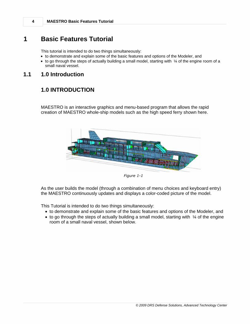
MAESTRO is an interactive graphics and menu-based program that allows the rapidcreation of MAESTRO whole-ship models such as the high speed ferry shown here.
Figure 1-1
As the user builds the model (through a combination of menu choices and keyboard entry)the MAESTRO continuously updates and displays a color-coded picture of the model.
This Tutorial is intended to do two things simultaneously:· to demonstrate and explain some of the basic features and options of the Modeler, and· to go through the steps of actually building a small model, starting with ¼ of the engine
room of a small naval vessel, shown below.
Basic Features Tutorial 5
© 2009 DRS Defense Solutions, Advanced Technology Center
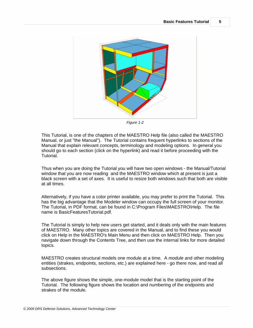
Figure 1-2
This Tutorial, is one of the chapters of the MAESTRO Help file (also called the MAESTROManual, or just "the Manual"). The Tutorial contains frequent hyperlinks to sections of theManual that explain relevant concepts, terminology and modeling options. In general youshould go to each section (click on the hyperlink) and read it before proceeding with theTutorial.
Thus when you are doing the Tutorial you will have two open windows - the Manual/Tutorialwindow that you are now reading and the MAESTRO window which at present is just ablack screen with a set of axes. It is useful to resize both windows such that both are visibleat all times.
Alternatively, if you have a color printer available, you may prefer to print the Tutorial. Thishas the big advantage that the Modeler window can occupy the full screen of your monitor. The Tutorial, in PDF format, can be found in C:\Program Files\MAESTRO\Help. The filename is BasicFeaturesTutorial.pdf.
The Tutorial is simply to help new users get started, and it deals only with the main featuresof MAESTRO. Many other topics are covered in the Manual, and to find these you wouldclick on Help in the MAESTRO's Main Menu and then click on MAESTRO Help. Then younavigate down through the Contents Tree, and then use the internal links for more detailedtopics.
MAESTRO creates structural models one module at a time. A module and other modelingentities (strakes, endpoints, sections, etc.) are explained here - go there now, and read allsubsections.
The above figure shows the simple, one-module model that is the starting point of theTutorial. The following figure shows the location and numbering of the endpoints andstrakes of the module.
MAESTRO Basic Features Tutorial6
© 2009 DRS Defense Solutions, Advanced Technology Center
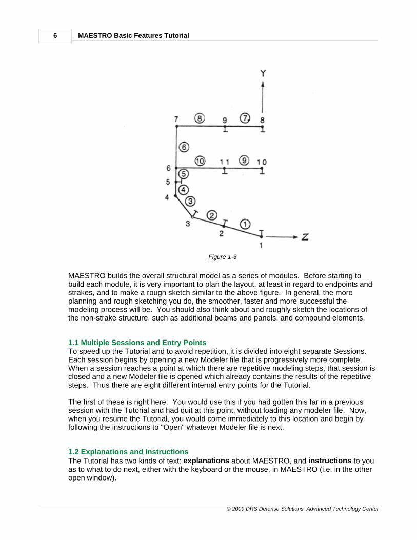
Figure 1-3
MAESTRO builds the overall structural model as a series of modules. Before starting tobuild each module, it is very important to plan the layout, at least in regard to endpoints andstrakes, and to make a rough sketch similar to the above figure. In general, the moreplanning and rough sketching you do, the smoother, faster and more successful themodeling process will be. You should also think about and roughly sketch the locations ofthe non-strake structure, such as additional beams and panels, and compound elements.
1.1 Multiple Sessions and Entry PointsTo speed up the Tutorial and to avoid repetition, it is divided into eight separate Sessions. Each session begins by opening a new Modeler file that is progressively more complete. When a session reaches a point at which there are repetitive modeling steps, that session isclosed and a new Modeler file is opened which already contains the results of the repetitivesteps. Thus there are eight different internal entry points for the Tutorial.
The first of these is right here. You would use this if you had gotten this far in a previoussession with the Tutorial and had quit at this point, without loading any modeler file. Now,when you resume the Tutorial, you would come immediately to this location and begin byfollowing the instructions to "Open" whatever Modeler file is next.
1.2 Explanations and InstructionsThe Tutorial has two kinds of text: explanations about MAESTRO, and instructions to youas to what to do next, either with the keyboard or the mouse, in MAESTRO (i.e. in the otheropen window).

Basic Features Tutorial 7
© 2009 DRS Defense Solutions, Advanced Technology Center
In order to distinguish these, the instructions are always enclosed in a box.
Opening the MAESTRO File – TUTORIAL ENTRY POINT 1
Open the first modeler file, EX1.MDL.
Move the cursor to the left end of the Main Menu, and click on the File option. Move thecursor down and click on Open. Go to the Samples folder (you are probably already thereby default, but if not go to C:\Program Files\MAESTRO\Models and Samples\Tutorial Models\Basic Features and then double click the icon for the file EX1.MDL
You should now see the model of ¼ of a ship's engine room that was pictured above.
1.2 2.0 General Concepts
2.0 GENERAL CONCEPTS
2.1 Getting Started, Files Used by the Modeler
Building a MAESTRO model involves the creation of a “modeler” file, with suffix MDL, whichstores the information about the model that is being built.
Some sample copies of these files are supplied with the MAESTRO. The complete Tutorialuses nine sample modeler files, EX1.MDL, EX1A.MDL, EX1B.MDL, EX1C.MDL , EX1D.MDL, EX1E.MDL, EX1F.MDL and EX1G.MDL, one for each session.
As a precaution, backup copies of these files are also supplied, in case any of them mightbe inadvertently corrupted due to an error in using MAESTRO. The name of each backupfile is the original name with BCK as the new file suffix; that is, EX1.BCK through EX1G.BCK.
MAESTRO begins by displaying the basic coordinate system and three reference planes. Inthe Main Menu (upper left of the Modeler screen; see here if you're not sure) the Filedropdown options are for opening and saving the various files – Open and Save for aModeler file, Import and Export a variety of files. The Exit option terminates the currentmodeling session. The Save option saves the current MAESTRO file. If desired, theMAESTRO file can be saved periodically during the session, and this is recommended. Most of these are standard Windows options, but if you need more information, all these Fileoptions are explained in File menu.
Saving the Modeler File
While you are building the model, MAESTRO is constantly storing the associatedinformation in a model file, jobname.MDL, where jobname is a name chosen by you. Rightnow jobname is EX1. This file is gradually built up as the modeling proceeds, and normallyit is saved at the end of each interactive modeling session. In this way the modeling processcan be stopped and recommenced later, any number of times.
Saving or Not Saving Files When Doing the Tutorial

MAESTRO Basic Features Tutorial8
© 2009 DRS Defense Solutions, Advanced Technology Center
Whenever you exit from the Modeler it will ask you whether you first want to save thechanges you have made to the current Modeler file. Normally you would, but when doingthe Tutorial the changes are just for exercise and they should NOT be saved, so that theMAESTRO file remains in the appropriate form for that session of the Tutorial. However, iffor some reason you have to exit in the middle of a session, you may prefer to save thechanges to avoid having to repeat them. In that case it is best to use the “Save As” optionand give the saved file some unique name. In that way you preserve the original file andyou can resume exactly where you left off, without having to repeat your changes.
2.2 Units
This submenu under the File menu refers to the overall structure, and logically it comes first,although this information can be supplied any time before making the first run, and there aredefaults for almost all of the items.
Click on File and then on Units...
In the present case we already have a modeler file, and so the system of units has alreadybeen chosen: the SI system, using Newtons and millimeters. If you were just starting abrand new model, you would see the default choice, which is Newtons and meters.
Click on the down arrow in Standard Unit Systems to see the seven choices of units. Thenclick Cancel.
To get an explanation of the Units submenu click here.
2.3 Job Information
This Dialog Box can be called up from the File menu (by clicking on File, and then on Job
Information) but it also has its own button - the top button in the Pre-ProcessingToolbar. Click here to see a figure defining all of the various toolbars.
Click on the Job Info button
At the top of the dialog box there is a window for defining the Job Title; this can be muchlonger and more informative than the MAESTRO file name. Then there are four groups ofinformation which are explained here.
2.4 Model Organization
At this point you should read Section Model Organization and its three subsections, whichintroduces the notion of "Parts", i.e. substructures and modules.
1.3 3.0 Defining Parts
3.0 DEFINING “PARTS” – SUBSTRUCTURES ANDMODULES

Basic Features Tutorial 9
© 2009 DRS Defense Solutions, Advanced Technology Center
In Section 2.4 you read Model Organization, which introduced the notion of "Parts", namelysubstructures and modules. Now you should go to Defining Parts, and just look brieflythrough the 14 steps in defining a substructure and the first module within that substructure. We will go through these later (Section 3.4 and Chapter 4) in more detail. Then go to theParts Tree and note the first two options described: “Set Current Part” and “Set View Part”.In the Parts Tree the Current Part is denoted by a supporting hand under the iconrepresenting that part (a folder for a substructure and a page for a module). The overallmodel is constructed part by part, and only one part at a time, The Current Part is the onethat is currently being worked on. Before working on any part, you must make it the CurrentPart. MAESTRO provides three icons that allow the user to set a particular Part as the
Current Part ( ), View Part ( ) or the View & Current Part ( ).
The View Part is the part that is currently visible. In the Parts Tree the View Part denoted bychanging the icon for that part to a blue-green color. These two options will be furtherexplained in Section 3.3.
3.1 Types of Structural Members and the Colors Used for Each
The colors correspond to the types of structural members that make up a MAESTROstructural model, as shown in the following figure.
Figure 3-1
STRAKE PANEL ELEMENTS
The panels of a strake are bounded by the strake edges and by the transverse planes(sections) that subdivide the module. The panels may be stiffened, either longitudinally

MAESTRO Basic Features Tutorial10
© 2009 DRS Defense Solutions, Advanced Technology Center
or transversely. Strake panels are colored blue and their stiffeners, if any, are shown asred lines. However, stiffeners are not displayed unless requested, because in a largemodel they cause too much clutter. Here, with our small model, we do want them. Theirdisplay is controlled by a toggle within the View Options Dialog. The button for this is on
the Viewing Toolbar. Its icon is a check mark because it contains many options.
Click the View Options button, and then click in the Stiffeners box, and then click on OK.
FRAME ELEMENTSIf a module is a segment of a ship hull, then it usually has a transverse framing systemthat supports the strake panels. The frame elements are the individual segments oftransverse frames that run across the strake, between the panels. They are beamelements, and their web usually lies in the transverse plane. Frame elements arecolored red.
GIRDER ELEMENTS
A girder is a series of beam elements, one element per section interval, runninglengthwise along the edge of a strake. These girder elements “belong” to that strake, inthe same way as the panel elements and the frame elements. However, for greatermodeling flexibility the girders have their own menu. Girders are colored yellow. In theEX1 example structure there are girder elements in the centerplane, and otherselsewhere.
ROD ELEMENTS
Rod (or strut) elements have only axial stiffness, and they can connect any two nodes. Rod elements are colored dark brown.. In the EX1 example there is one rod element,representing a centerline pillar.
TRIANGLES
Triangles are three-node elements, portrayed as light green. In the EX1 example thereare two of them in the engine foundation and three in the transverse bulkhead.
ADDITIONAL BEAMS
These are beams that are not part of a strake. Therefore, unlike girders and frames,they are not limited to a longitudinal or transverse orientation; rather, they can be placedbetween any two nodes. Also, they are defined individually rather than as a group ofelements. Additional beams are light brown in color. In the EX1 example, someadditional beams are used as bulkhead stiffeners.
ADDITIONAL PANELS
These are quadrilateral panels ("quads") that are not part of a strake, and whichtherefore can connect any four nodes (subject to the limits on warping and aspect ratiodictated by finite element theory). They are light bluish-green, and their stiffeners, if any,are shown as red lines. In the example there are two of them forming the uptake trunkbetween the main deck and the second deck, and another two in the engine foundation.

Basic Features Tutorial 11
© 2009 DRS Defense Solutions, Advanced Technology Center
COMPOUND ELEMENTS
Compound elements provide a convenient method for quickly creating repetitivetransverse structure. A compound is a collection of heterogeneous element types thatrepeats itself with some well-defined pattern along the module’s longitudinal direction. Acompound is dark green, and in the EX1 example the transverse bulkhead is acompound, consisting of several quadrilaterals and triangles. But since there is only onebulkhead in the EX1 model, this example does not illustrate the ability of a compound tooccur repetitively.
3.2 Some Basic Viewing Options
At this point we will look at some of the ways to control the view.
Click the View menu in the Main Menu
This shows the major submenus for controlling the view. They each have numerouschoices, which are discussed in View Options and View Menu in the Manual. But forconvenience the most useful choices have also been gathered together into another menuthat you obtain by placing the cursor anywhere within the Modeling Space (even within themodel) and clicking the right mouse button.
Cancel the View options (by clicking it again). Move the cursor to anywhere within theModeling Space and click the right button.
Zoom In is used to decrease the scope of a Modeling Space by magnifying the model. Theidea is to construct a small box that has the same shape as the Model Space and place itover the region to be magnified. You make the box by clicking where one of its corners is tobe, and then moving the cursor (the box begins to grow) to where you want the oppositecorner to be and clicking again. Note that it is two clicks, not a click-down-and-drag. See Using the Mouse an Shortcut keys for a discussion on mouse functionality.
Note: If you have a wheel-mouse you don't need the menu. You can zoom simply byrotating the wheel, forward to zoom in, back to zoom out.
Click on Zoom In and draw a box around the area of interest by clicking on oppositecoreners.
Zoom Out is used to increase the scope of a Modeling Space by shrinking the model. Afterselecting Zoom Out, you use two clicks to draw a box on the screen. The current view areawill be shrunk to fit into the box, and other portions of the model will show in the left overarea.
Right click, click on Zoom Out and draw a box (by clicking on opposite corners) into whichyou want the current view to be "squeezed".
MAESTRO Basic Features Tutorial12
© 2009 DRS Defense Solutions, Advanced Technology Center
Fit adjusts the Zoom and Pan parameters so that the View Part is entirely visible in theModeling Space with the part’s extents just fitting inside the Modeling Space. This is mucheasier to use than Zoom Out.
Since the result of the Zoom Out probably did not give an exact fit, right click and then clickon Fit.
Pan moves the focus of the window from side-to-side and up-and-down without any of thesize changes associated with zooming. Hold down the Shift key while you click-down-and-drag.
By default, the model is always placed at the center of the Modeling Space. When DialogBoxes (such as the Units and Job Info menus) are created they too are placed at the center. Therefore if you want to see both together you can use the Pan option to move the modelaway from the center. For example,
Right click, click on Pan, and then move the model to the right by holding down the Shift keywhile you click-down-and-drag the model to the right.
Again, if you have a wheel-mouse you don't need the menu. You can pan simply bypressing the Shift key while you click-down-and-drag using the wheel.
Undo View Change will undo the last change to the model view made. For example, if themodel is being viewed in the profile view and is changed to body plan, choosing this optionwill return the view to the profile.
Right click and then move the model back to the center by clicking on Undo View Change
The other options rotate the model into predefined positions. These are explained in Standard Views. Southeast is the default view. Try them each in succession.
Next try spinning the model. If you have a "wheel-mouse " you should use the wheel toclick-down-and-drag in the direction of the desired spin.
Hold the wheel down and drag.
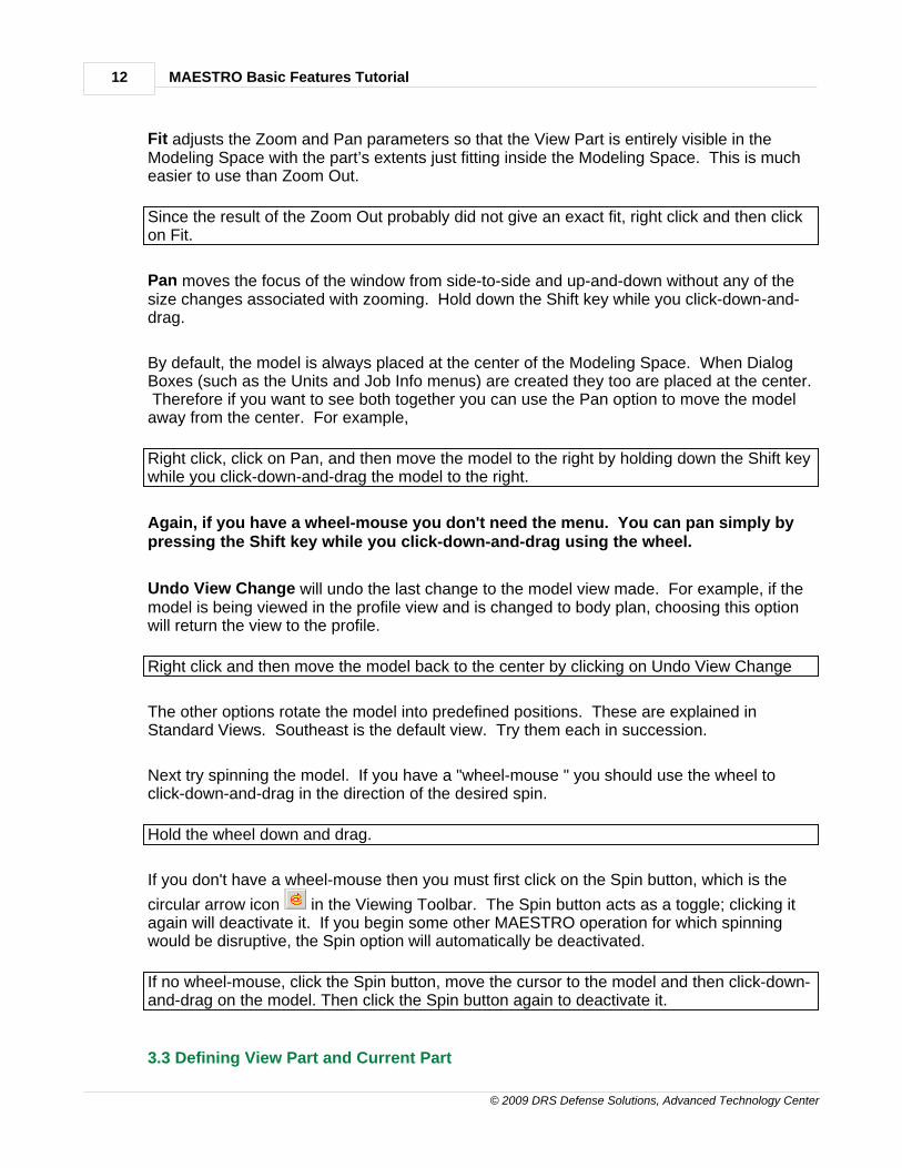
If you don't have a wheel-mouse then you must first click on the Spin button, which is the
circular arrow icon in the Viewing Toolbar. The Spin button acts as a toggle; clicking itagain will deactivate it. If you begin some other MAESTRO operation for which spinningwould be disruptive, the Spin option will automatically be deactivated.
If no wheel-mouse, click the Spin button, move the cursor to the model and then click-down-and-drag on the model. Then click the Spin button again to deactivate it.
3.3 Defining View Part and Current Part
Basic Features Tutorial 13
© 2009 DRS Defense Solutions, Advanced Technology Center
Two additional concepts that are crucial to effective use of MAESTRO are the view part andthe current part. Our current example is too small and simple to demonstrate this feature,and so we will temporarily change to a full ship model – the “fast ferry” that is described inReference [19].
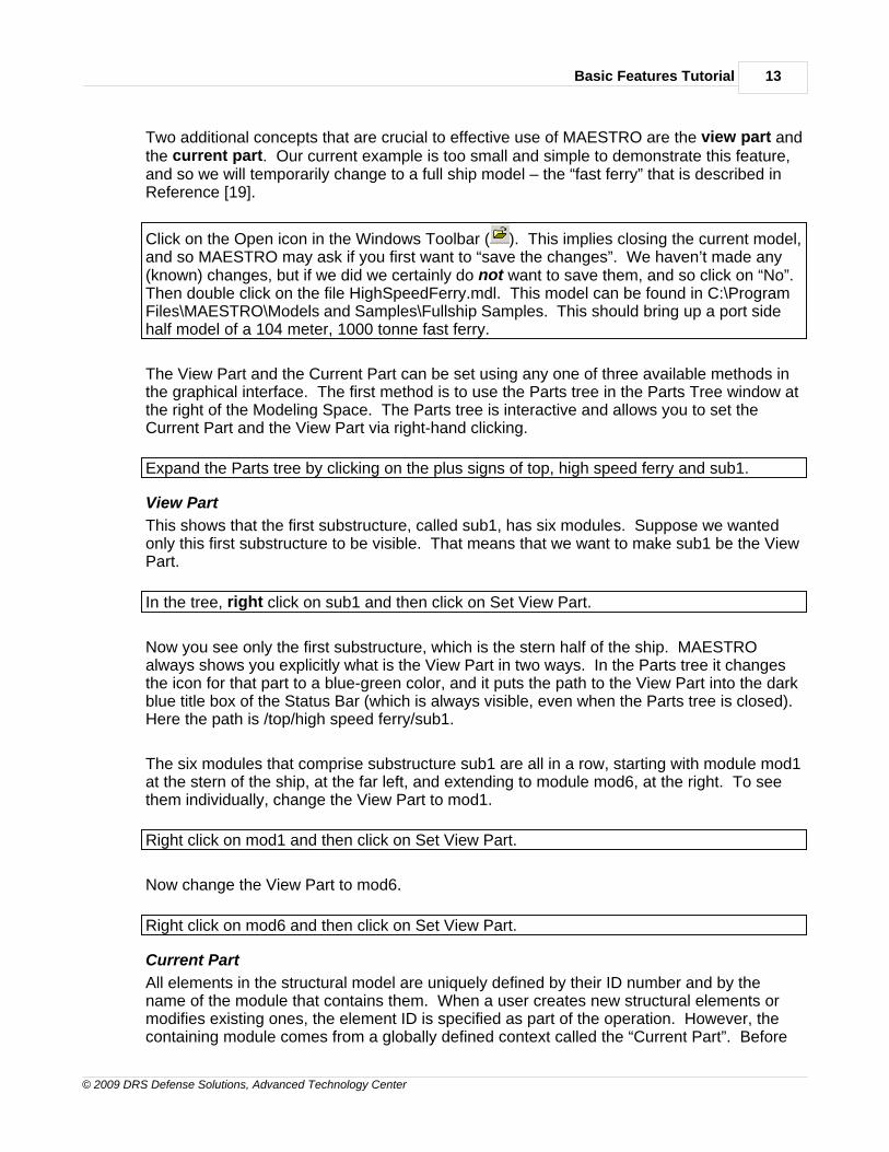
Click on the Open icon in the Windows Toolbar ( ). This implies closing the current model,and so MAESTRO may ask if you first want to “save the changes”. We haven’t made any(known) changes, but if we did we certainly do not want to save them, and so click on “No”.Then double click on the file HighSpeedFerry.mdl. This model can be found in C:\ProgramFiles\MAESTRO\Models and Samples\Fullship Samples. This should bring up a port sidehalf model of a 104 meter, 1000 tonne fast ferry.
The View Part and the Current Part can be set using any one of three available methods inthe graphical interface. The first method is to use the Parts tree in the Parts Tree window atthe right of the Modeling Space. The Parts tree is interactive and allows you to set theCurrent Part and the View Part via right-hand clicking.
Expand the Parts tree by clicking on the plus signs of top, high speed ferry and sub1.
View Part
This shows that the first substructure, called sub1, has six modules. Suppose we wantedonly this first substructure to be visible. That means that we want to make sub1 be the ViewPart.
In the tree, right click on sub1 and then click on Set View Part.
Now you see only the first substructure, which is the stern half of the ship. MAESTROalways shows you explicitly what is the View Part in two ways. In the Parts tree it changesthe icon for that part to a blue-green color, and it puts the path to the View Part into the darkblue title box of the Status Bar (which is always visible, even when the Parts tree is closed). Here the path is /top/high speed ferry/sub1.
The six modules that comprise substructure sub1 are all in a row, starting with module mod1at the stern of the ship, at the far left, and extending to module mod6, at the right. To seethem individually, change the View Part to mod1.
Right click on mod1 and then click on Set View Part.
Now change the View Part to mod6.
Right click on mod6 and then click on Set View Part.
Current Part
All elements in the structural model are uniquely defined by their ID number and by thename of the module that contains them. When a user creates new structural elements ormodifies existing ones, the element ID is specified as part of the operation. However, thecontaining module comes from a globally defined context called the “Current Part”. Before
MAESTRO Basic Features Tutorial14
© 2009 DRS Defense Solutions, Advanced Technology Center
populating a particular module with structural elements or modifying existing elements theuser must first set the Current Part to be that module, after which all following elementoperations will apply to that module. To create or modify elements in a different module, youmust first set the Current Part to be that other module. If the View Part is a substructure andthen all of those its modules will be visible. The Current Part can only be a single part, andusually it is a module. Suppose we wanted to work on the sixth module, called mod6.
In the tree, right click on mod6 and then click on Set Current Part.
Here again the Modeler always shows you explicitly which module is the Current Part in twoways. In the Parts tree it places a supporting hand under the icon for that module, and itputs the path to the Current Part into the Status Bar, at the lower right of the screen (this baris always visible, even when the Parts tree is closed). Here the path is /top/high speed ferry/sub1/mod6. Now if we brought up any of the modeling dialog boxes and began makingchanges (for example, creating new strakes) the changes would occur in the sixth module.
At this point mod6 is both the View Part and the Current Part. The View Part could be all ofsub1 (six modules) or it could be the whole ship. But it is usually better to make the ViewPart be the same as the Current Part because then you can see more detail.
Since mod6 is the Current Part we are now able to examine the properties of that moduleand, if desired, to make changes. For example, let us examine one of its strakes. To do
this we call up the Strake Dialog Box, which we do by clicking on the Strake button in thePre-Processing Toolbar.
Click on the Strake button.
Here is the first example of needing to move the model and the Dialog Box so that they bothcan be seen. We will move the Dialog Box up and the model down.
Move the Dialog box up by putting the cursor on its blue title box and using a click-down-and-drag operation. Then right click anywhere within the Modeling Space, click Pan, holddown Shift and drag the model down.
Because we have set mod6 as the Current Part, the Modeler has loaded the Strake DialogBox with all of the information about the strakes of module mod6.
The Strake Dialog Box is subdivided into pages that you access by clicking on their tab. Youcan select a strake either by name or by number, using either of the two windows at the topof the box. In both cases, there are two ways to do so. You can either click the down arrowand then select from the drop-down list, or you can click in the window and then move thecursor to the model and click on the strake that you want.
Click in the Name window and then click on a strake in mod6. (Note that if the View Partconsisted of several modules (e.g. sub1 has six modules) you would have to be careful toclick somewhere on module mod6.)
The Modeler outlines the selected strake, and puts its name and number in the windows. Do this repeatedly, to get the hang of it.

Basic Features Tutorial 15
© 2009 DRS Defense Solutions, Advanced Technology Center
Click in the ID (number) window and then click on another strake in mod6.
Now use the other method. In the Name box, click the down arrow and then click on thename of the first strake (bottom #1)
The Modeler outlines strake 1 and puts its properties in the various windows of the variouspages. For example, Click on the Plating tab and notice that the material is an aluminumalloy.
Click the Stiffeners tab and notice that in this strake the stiffeners are at 0.25 m spacing.
Using Viewing Toolbar Buttons to Set View Part and Current Part
There is another way to set the View Part and the Current Part. To demonstrate this weneed to have a View Part that consists of several modules, say sub1.
Go to the Parts Tree, right click on sub1 and then click on Set View Part.
In the Viewing Toolbar the three buttons to the right of the View Options button offer adifferent way to set the Current Part and the View Part.
The symbology is the same; a supporting hand denotes the Current Part and a blue-greencolor denotes the View Part. The procedure is to first click on the appropriate button andthen click on the relevant part in the model itself.
Click on the Current Part button and then move the cursor to module mod1, which is theoverhanging stern, at the extreme left of the model, and click on it.
Two things happen. The Modeler now outlines strake 1 of module mod1, and in the Partstree the supporting hand is now under the mod1 icon.
Likewise, we can use the Set View Part button (to the right of the Set Current Part button) toset the View Part. The icon has a viewing window connected to a Part.
Click the Set View Part button and then, as before, move the cursor to module mod1, andclick on it.
Now the View Part is only mod1, and we can see all of it. Thus as mentioned before it isusually preferable (but not necessary) to make the Current Part also be the View Part.
We are finished with the Strake Dialog Box , so let's close it.
Click either the Close button at lower right or the X at upper right.
For the next topic we again want to view the six modules of sub1.
In the Parts tree, right click on sub1 and make it the View Part.

MAESTRO Basic Features Tutorial16
© 2009 DRS Defense Solutions, Advanced Technology Center
3.4 The Parts Dialog Box – Defining Substructures and Modules
Now that we have seen a typical dialog box (the Strakes box) we are ready to look at onethat is not typical - the Parts Dialog Box. It is unusual because, instead of dealing with justone Part (a module) it deals with all of the Parts (substructures and modules). It is thedialog box for creating Parts and for changing their most basic properties (name, location,orientation and section spacing). The Parts Dialog Box can be obtained via the Parts optionin the Main Menu (Model > Parts > Create/Modify) but it also has its own button in the Pre-Processing Toolbar on the left side of the screen.
Move the cursor to the second icon (it will identify itself as the Parts icon) and click on it.
The title of the Parts Dialog is “Substructures and Modules” because those are the Parts thatit deals with.
Here again it is best to move the model and the Dialog Box so that they both can be seen.
Move the Dialog box down by dragging its title box. Then right click anywhere within theModeling Space, click Pan, hold down Shift and drag the model up until it is fully visible.
The Parts Dialog Box has its own Parts tree.
Expand the tree by clicking on the first three + signs.
This is the same tree as in the large Parts tree window (expand that one also three times)but it has direct control over the pages of the Parts Dialog Box, whereas the larger tree doesnot. The biggest difference is that in the small Parts tree you select a part just by clicking onit (either its name or its icon). You do not need to make it be the Current Part. That isneeded in all the other dialog boxes, but not in the Parts Dialog box. We can illustrate thisusing the Locations page.
Click the Locations tab. Now go to the small tree and click on mod1 (name or icon) so thatthe mod1 name becomes highlighted.
You will see that in the Origin Location window the X value has changed to –4000. This isbecause the sub1 origin is in line with the main transom, and the origin of mod1, theoverhanging portion of the stern, is located 4000 mm aft of the substructure origin.
Click on mod2, then on mod3, mod4, etc. and see the origin location change.
Each time you select a module you are telling the Modeler that you want to work on thatmodule, and it will load all of the pages with whatever data has been defined for that module. Thus in the Parts Dialog you must click directly on a Part icon to select that Part, whereas inthe other dialog boxes you must explicitly set it as the Current Part, either by right clicking orby the Set Current Part button in the Viewing Toolbar.
A substructure is simply a convenient grouping of modules. Whereas modules containstrakes and other structural entities, a substructure has only two properties: its name and its
Basic Features Tutorial 17
© 2009 DRS Defense Solutions, Advanced Technology Center
location. Therefore the only time that a substructure can be created or modified is now,within the Parts Dialog Box, and the only relevant pages are the General page (to specifythe name) and the Location page (to specify the location of the origin and the rotations ofthe axes).
Click on the General tab and then in the tree click on sub1. The path to sub1 now appearsin the Part Name box, confirming that any changes that are made now will apply tosubstructure sub1.
As an example, let us change the X location of the origin of sub1 from 0 to 10000.
Go back to the Location page and type in 10000 for the X location of the origin and thenclick Modify.
The entire substructure moves 10000 mm away from the structure origin. Since we don’treally want this
Double click in the X-window, type 0 and then click Modify.
Let's now make some changes in the section spacing of one of the modules.
Click on the Sections tab and in the tree select mod1.
You will see the section data for mod1 pop into the window: four section intervals at 1000mm spacing. As an exercise, let’s change the second spacing to 2000.
Click on the 2 under Index and then click on Re-space. Enter 2000 and click OK.
The 2000 value appears but the model has not yet changed because for safety all majordialog boxes have a Modify button, and changes do not occur until that button is clicked.
Click on Modify.
Unlike changing the location of sub1, this was a structural modification to module mod1. Therefore the Modeler has automatically set mod1 to be both the Current Part and the ViewPart. In the Parts Dialog box (and only this box) the setting of View Part and Current Part isdriven by whatever changes you make. Changing the View Part makes the change easier tosee. Of course you can change it back if you wish.
We could also add another section with a spacing of say 2000 mm.
Click on Add, type 1 in the Insert window, double click in the lower window and type 2000,click OK and then click Modify.
Of course we don’t want these changes, so let’s remove them.
MAESTRO Basic Features Tutorial18
© 2009 DRS Defense Solutions, Advanced Technology Center
Click on 5 under Index and then click on Remove. Then click on 2 under Index, then onRe-space, type 1000, click OK and then Modify.
You can now have a look at the Default Values page. The entries there are default valuesfor various properties of strakes and other modeling entities. Setting defaults saves timebecause then the values for individual strakes or entities only have to be defined if they aredifferent from the default value.
We are now finished with this model and will go back to the simple one-module model ofEX1.
Close the Parts Dialog Box
Click either the Close button at lower right or the X at upper right.
Since we had earlier opened that modeler file (EX1.MDL) it will be included as one of the“recently opened” files on the dropdown list under the File menu.
Click on File, go down to EX1.MDL and click on it. If asked about saving changes click on“No”.
1.4 4.0 Adding Modules and Creating a New Model
4.0 ADDING MODULES AND CREATING AN ENTIRELYNEW MODEL
Chapters 4.0 through 12.0 of the Tutorial are devoted to making a second module. Thisprocess will demonstrate most of the basic steps in creating a model, but it does not includethe first few steps that are required when you create an entirely new model. Therefore thethird part of this chapter presents a summary of these first few steps. It is a sort of checklistthat you can use when you make an new model.
4.1 Adding a Module
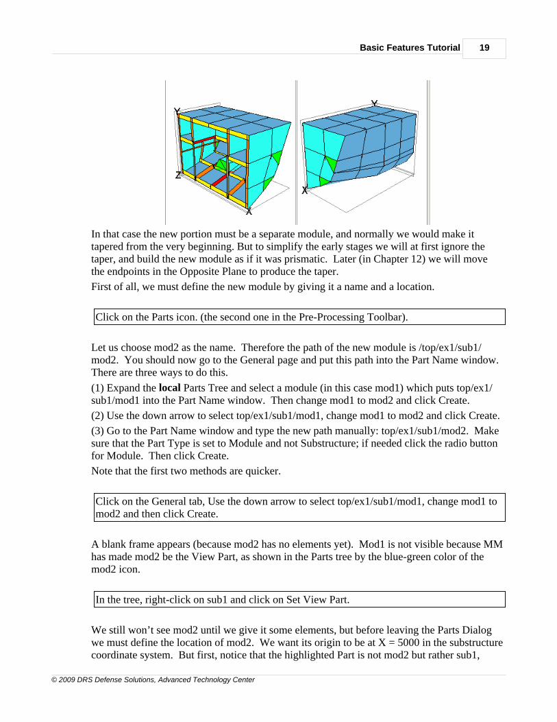
The current model is a half length of the engine room of a small naval vessel (and only theport half). As an exercise, we will construct the other half length as a second module. If thecomplete engine room was prismatic we would just enlarge the current module by adding twomore sections and then creating the opposite bulkhead. But let's say that at the midlength ofthe engine room the hull begins to taper, as shown in these SouthEast and NorthEast views.
Basic Features Tutorial 19
© 2009 DRS Defense Solutions, Advanced Technology Center
In that case the new portion must be a separate module, and normally we would make ittapered from the very beginning. But to simplify the early stages we will at first ignore thetaper, and build the new module as if it was prismatic. Later (in Chapter 12) we will movethe endpoints in the Opposite Plane to produce the taper.
First of all, we must define the new module by giving it a name and a location.
Click on the Parts icon. (the second one in the Pre-Processing Toolbar).
Let us choose mod2 as the name. Therefore the path of the new module is /top/ex1/sub1/mod2. You should now go to the General page and put this path into the Part Name window.There are three ways to do this.
(1) Expand the local Parts Tree and select a module (in this case mod1) which puts top/ex1/sub1/mod1 into the Part Name window. Then change mod1 to mod2 and click Create.
(2) Use the down arrow to select top/ex1/sub1/mod1, change mod1 to mod2 and click Create.
(3) Go to the Part Name window and type the new path manually: top/ex1/sub1/mod2. Makesure that the Part Type is set to Module and not Substructure; if needed click the radio buttonfor Module. Then click Create.
Note that the first two methods are quicker.
Click on the General tab, Use the down arrow to select top/ex1/sub1/mod1, change mod1 tomod2 and then click Create.
A blank frame appears (because mod2 has no elements yet). Mod1 is not visible because MMhas made mod2 be the View Part, as shown in the Parts tree by the blue-green color of themod2 icon.
In the tree, right-click on sub1 and click on Set View Part.
We still won’t see mod2 until we give it some elements, but before leaving the Parts Dialogwe must define the location of mod2. We want its origin to be at X = 5000 in the substructurecoordinate system. But first, notice that the highlighted Part is not mod2 but rather sub1,
MAESTRO Basic Features Tutorial20
© 2009 DRS Defense Solutions, Advanced Technology Center
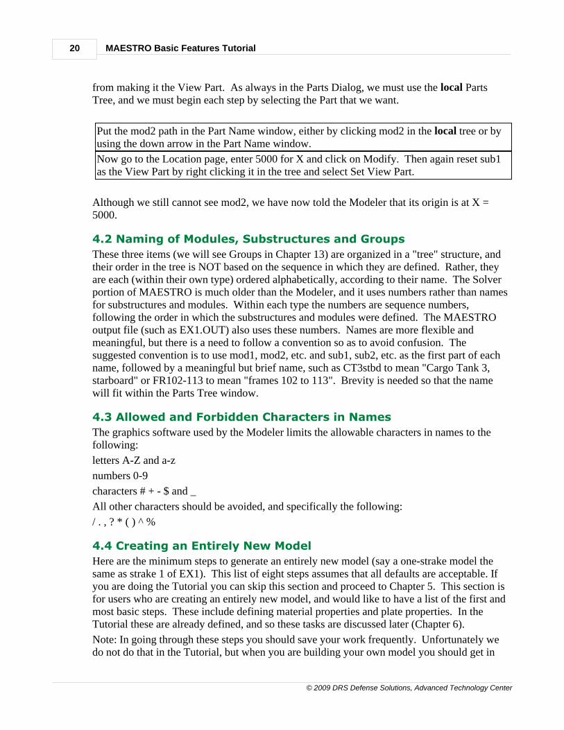
from making it the View Part. As always in the Parts Dialog, we must use the local PartsTree, and we must begin each step by selecting the Part that we want.
Put the mod2 path in the Part Name window, either by clicking mod2 in the local tree or byusing the down arrow in the Part Name window.
Now go to the Location page, enter 5000 for X and click on Modify. Then again reset sub1as the View Part by right clicking it in the tree and select Set View Part.
Although we still cannot see mod2, we have now told the Modeler that its origin is at X =5000.
4.2 Naming of Modules, Substructures and Groups
These three items (we will see Groups in Chapter 13) are organized in a "tree" structure, andtheir order in the tree is NOT based on the sequence in which they are defined. Rather, theyare each (within their own type) ordered alphabetically, according to their name. The Solverportion of MAESTRO is much older than the Modeler, and it uses numbers rather than namesfor substructures and modules. Within each type the numbers are sequence numbers,following the order in which the substructures and modules were defined. The MAESTROoutput file (such as EX1.OUT) also uses these numbers. Names are more flexible andmeaningful, but there is a need to follow a convention so as to avoid confusion. Thesuggested convention is to use mod1, mod2, etc. and sub1, sub2, etc. as the first part of eachname, followed by a meaningful but brief name, such as CT3stbd to mean "Cargo Tank 3,starboard" or FR102-113 to mean "frames 102 to 113". Brevity is needed so that the namewill fit within the Parts Tree window.
4.3 Allowed and Forbidden Characters in Names
The graphics software used by the Modeler limits the allowable characters in names to thefollowing:
letters A-Z and a-z
numbers 0-9
characters # + - $ and _
All other characters should be avoided, and specifically the following:
/ . , ? * ( ) ^ %
4.4 Creating an Entirely New Model
Here are the minimum steps to generate an entirely new model (say a one-strake model thesame as strake 1 of EX1). This list of eight steps assumes that all defaults are acceptable. Ifyou are doing the Tutorial you can skip this section and proceed to Chapter 5. This section isfor users who are creating an entirely new model, and would like to have a list of the first andmost basic steps. These include defining material properties and plate properties. In theTutorial these are already defined, and so these tasks are discussed later (Chapter 6).
Note: In going through these steps you should save your work frequently. Unfortunately wedo not do that in the Tutorial, but when you are building your own model you should get in
Basic Features Tutorial 21
© 2009 DRS Defense Solutions, Advanced Technology Center
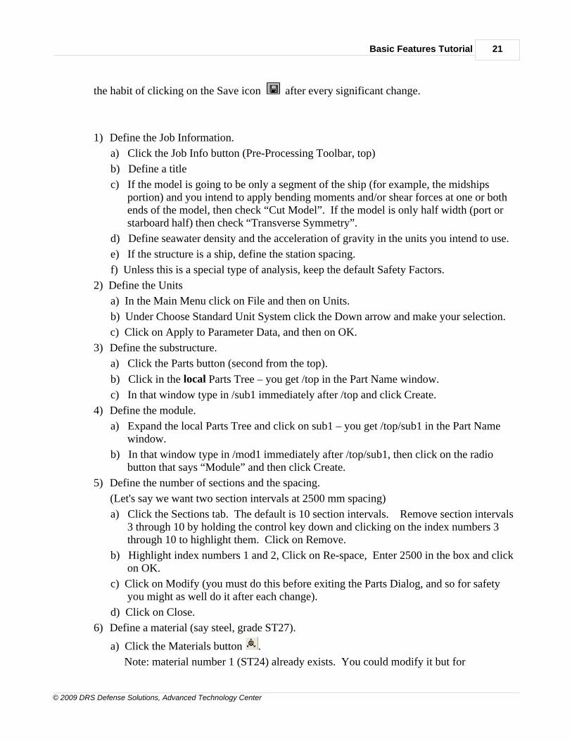
the habit of clicking on the Save icon after every significant change.
1) Define the Job Information.
a) Click the Job Info button (Pre-Processing Toolbar, top)
b) Define a title
c) If the model is going to be only a segment of the ship (for example, the midshipsportion) and you intend to apply bending moments and/or shear forces at one or bothends of the model, then check “Cut Model”. If the model is only half width (port orstarboard half) then check “Transverse Symmetry”.
d) Define seawater density and the acceleration of gravity in the units you intend to use.
e) If the structure is a ship, define the station spacing.
f) Unless this is a special type of analysis, keep the default Safety Factors.
2) Define the Units
a) In the Main Menu click on File and then on Units.
b) Under Choose Standard Unit System click the Down arrow and make your selection.
c) Click on Apply to Parameter Data, and then on OK.
3) Define the substructure.
a) Click the Parts button (second from the top).
b) Click in the local Parts Tree – you get /top in the Part Name window.
c) In that window type in /sub1 immediately after /top and click Create.
4) Define the module.
a) Expand the local Parts Tree and click on sub1 – you get /top/sub1 in the Part Namewindow.
b) In that window type in /mod1 immediately after /top/sub1, then click on the radiobutton that says “Module” and then click Create.
5) Define the number of sections and the spacing.
(Let's say we want two section intervals at 2500 mm spacing)
a) Click the Sections tab. The default is 10 section intervals. Remove section intervals3 through 10 by holding the control key down and clicking on the index numbers 3through 10 to highlight them. Click on Remove.
b) Highlight index numbers 1 and 2, Click on Re-space, Enter 2500 in the box and clickon OK.
c) Click on Modify (you must do this before exiting the Parts Dialog, and so for safetyyou might as well do it after each change).
d) Click on Close.
6) Define a material (say steel, grade ST27).
a) Click the Materials button .
Note: material number 1 (ST24) already exists. You could modify it but for
MAESTRO Basic Features Tutorial22
© 2009 DRS Defense Solutions, Advanced Technology Center
instructional purposes define a second material type, say ST27.
b) Click on ID to get the number 2.
c) Give it a name, say ST27.
d) Define the properties:
E = 208000 N/mm2, ? = 0.3, density = 7.85E-6 kg/mm3,
Yield Stress = 265. N/mm2 , sult = 350. N/mm2 ,sYred = 265. N/mm2 ,
Weld residual stress ratio = 0.1
Structural proportional limit ratio = 1.
e) Click on Create.
7) Define a plate property.
a) Click the Property button .
b) On the Plate page, in the Name box enter "Plate Type 1".
(later, when you have used this plate type, you can change
the name to something that reflects that usage).
c) Go to the bottom, click on the Layer button and then on Add.
(This one is NOT intuitive; we don’t think of a plate as being one layer)
ST24 will appear as the material because that is the first material type.
d) Click on ST24 to generate a Down arrow.
e) Click the Down arrow and select ST27.
f) Define the thickness (enter 12) and click on Create.
g) Close the dialog box.
8) From here on the Tutorial chapters tell you how to proceed, starting with Chapter 5,Creating Endpoints.
1.5 5.0 Creating Endpoints
5.0 CREATING ENDPOINTS
We are now finished with the Parts Dialog and ready to define some end points in mod2. Endpoints are the means by which MAESTRO generates the three-dimensional mesh of finiteelement nodes. End points are illustrated here and are explained in the Manual underCreating Endpoints & Additional Notes.
To begin, close the Parts Dialog and bring up the End Points Dialog.
Cancel the Parts Dialog by clicking the X at the upper right. Then click on the fourth buttonof the Pre-Processing Toolbar to get the End Points Dialog box. As always, move it awayfrom the model, say downwards so as to keep the Parts Tree visible. Right click, Pan andDrag to make the model fully visible.
Basic Features Tutorial 23
© 2009 DRS Defense Solutions, Advanced Technology Center
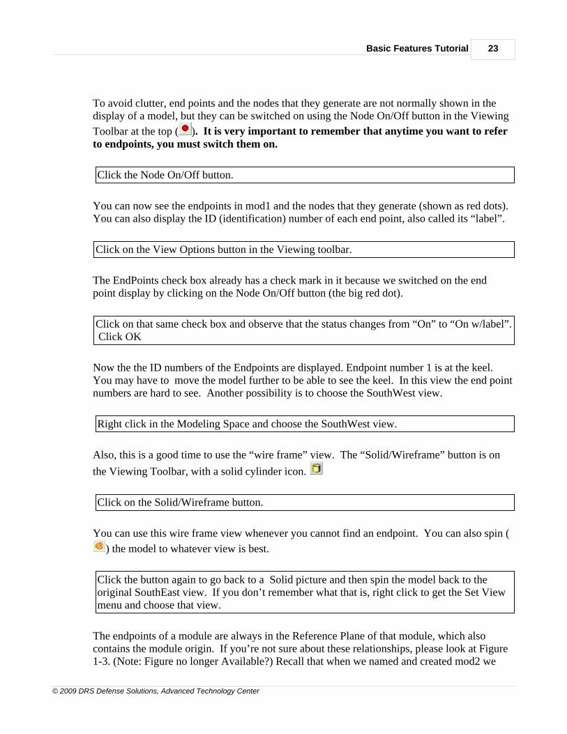
To avoid clutter, end points and the nodes that they generate are not normally shown in thedisplay of a model, but they can be switched on using the Node On/Off button in the Viewing
Toolbar at the top ( ). It is very important to remember that anytime you want to referto endpoints, you must switch them on.
Click the Node On/Off button.
You can now see the endpoints in mod1 and the nodes that they generate (shown as red dots).You can also display the ID (identification) number of each end point, also called its “label”.
Click on the View Options button in the Viewing toolbar.
The EndPoints check box already has a check mark in it because we switched on the endpoint display by clicking on the Node On/Off button (the big red dot).
Click on that same check box and observe that the status changes from “On” to “On w/label”. Click OK
Now the the ID numbers of the Endpoints are displayed. Endpoint number 1 is at the keel. You may have to move the model further to be able to see the keel. In this view the end pointnumbers are hard to see. Another possibility is to choose the SouthWest view.
Right click in the Modeling Space and choose the SouthWest view.
Also, this is a good time to use the “wire frame” view. The “Solid/Wireframe” button is on
the Viewing Toolbar, with a solid cylinder icon.
Click on the Solid/Wireframe button.
You can use this wire frame view whenever you cannot find an endpoint. You can also spin (
) the model to whatever view is best.
Click the button again to go back to a Solid picture and then spin the model back to theoriginal SouthEast view. If you don’t remember what that is, right click to get the Set Viewmenu and choose that view.
The endpoints of a module are always in the Reference Plane of that module, which alsocontains the module origin. If you’re not sure about these relationships, please look at Figure1-3. (Note: Figure no longer Available?) Recall that when we named and created mod2 we
MAESTRO Basic Features Tutorial24
© 2009 DRS Defense Solutions, Advanced Technology Center
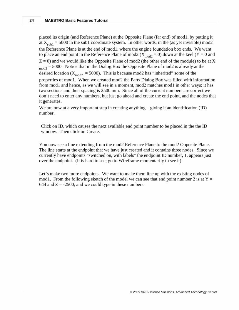
placed its origin (and Reference Plane) at the Opposite Plane (far end) of mod1, by putting itat Xsub1 = 5000 in the sub1 coordinate system. In other words, in the (as yet invisible) mod2
the Reference Plane is at the end of mod1, where the engine foundation box ends. We wantto place an end point in the Reference Plane of mod2 (Xmod2 = 0) down at the keel (Y = 0 and
Z = 0) and we would like the Opposite Plane of mod2 (the other end of the module) to be at X
mod2 = 5000. Notice that in the Dialog Box the Opposite Plane of mod2 is already at the
desired location (Xmod2 = 5000). This is because mod2 has “inherited” some of the
properties of mod1. When we created mod2 the Parts Dialog Box was filled with informationfrom mod1 and hence, as we will see in a moment, mod2 matches mod1 in other ways: it hastwo sections and their spacing is 2500 mm. Since all of the current numbers are correct wedon’t need to enter any numbers, but just go ahead and create the end point, and the nodes thatit generates.
We are now at a very important step in creating anything – giving it an identification (ID) number.
Click on ID, which causes the next available end point number to be placed in the the IDwindow. Then click on Create.
You now see a line extending from the mod2 Reference Plane to the mod2 Opposite Plane. The line starts at the endpoint that we have just created and it contains three nodes. Since wecurrently have endpoints “switched on, with labels” the endpoint ID number, 1, appears justover the endpoint. (It is hard to see; go to Wireframe momentarily to see it).
Let’s make two more endpoints. We want to make them line up with the existing nodes ofmod1. From the following sketch of the model we can see that end point number 2 is at Y =644 and Z = -2500, and we could type in these numbers.

Basic Features Tutorial 25
© 2009 DRS Defense Solutions, Advanced Technology Center
But typing numbers is slow, and the Modeler allows you to generate numbers automaticallyby clicking on appropriate nodes in the displayed model. Whenever you are creating newnodes or elements, you must give them an ID number. The usual way to do this is to click onthe ID button, which brings up the next available ID number. If you then click on the firstwindow for which a number is needed, this tells the Modeler that your next click is going tobe at a node from which it should obtain that number. In the present case there is already anode in mod1 exactly at the point where we want to put the second end point of mod2, and sowe will use it.
Click on ID to get the next end point number, then click in the first window that needs anumber, which is the Reference X window. This signals that you are next going to click on anode that has the desired coordinates. This node is at the lowest corner of the enginefoundation box. Move the cursor to that node and click on it.
You will see the three coordinates of that node pop into the first three coordinate windows,and if you have picked the correct node those numbers will be X = 0, Y = 644 and Z = –2500.

MAESTRO Basic Features Tutorial26
© 2009 DRS Defense Solutions, Advanced Technology Center
Since the model is prismatic; with no taper or warp, we know that at the Opposite Plane (X =5000) the Y and Z coordinates are to be the same. Therefore as a shortcut we can use thesame node to generate the three numbers for the Opposite Plane, and then change X from 0 to5000.
Click in the Opposite X window, then click on the same node as before. This generates threenumbers. Double click on the first number (X = 0) and type 5000. Then click Create.
Repeat this sequence to create the third end point.
Click on ID to get the next end point number (3) then click in the Reference X window. Move the cursor to the appropriate node (outboard end of the engine foundation box) andclick on it. Now click in the Opposite X window and then click on the same node. Doubleclick on the first number (X = 0) and type 5000. Then click Create.
1.6 6.0 Materials and Properties
6.0 MATERIALS AND PROPERTIES – TUTORIAL ENTRYPOINT 2
At this point, whether you are continuing from the first session or re-entering the Tutorial, youwill need to open a file called EX1A.MDL which is a copy of the model that was made in thefirst modeling session.
Click the Open Existing File icon, go to the Samples folder and then double click EX1A.MDL. Do not save the current model.
To make the modeling space as large as possible
go to Tools > Toolbars > Refine Elements and toggle it off. Do not close the Parts Treewindow.
We would like to see modules mod1 and mod2 together, and so
expand the Parts Tree, right click on sub1 and make it be the View Part.
In the first modeling session we created three end points. In order to see them
Click View Options and click twice on the EndPoints tick box.
Basic Features Tutorial 27
© 2009 DRS Defense Solutions, Advanced Technology Center
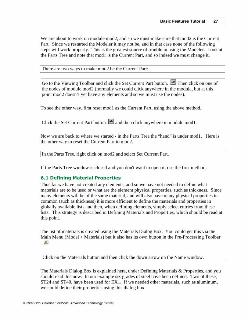
We are about to work on module mod2, and so we must make sure that mod2 is the CurrentPart. Since we restarted the Modeler it may not be, and in that case none of the followingsteps will work properly. This is the greatest source of trouble in using the Modeler. Look atthe Parts Tree and note that mod1 is the Current Part, and so indeed we must change it.
There are two ways to make mod2 be the Current Part:
Go to the Viewing Toolbar and click the Set Current Part button. Then click on one ofthe nodes of module mod2 (normally we could click anywhere in the module, but at thispoint mod2 doesn’t yet have any elements and so we must use the nodes).
To see the other way, first reset mod1 as the Current Part, using the above method.
Click the Set Current Part button and then click anywhere in module mod1.
Now we are back to where we started - in the Parts Tree the “hand” is under mod1. Here isthe other way to reset the Current Part to mod2.
In the Parts Tree, right click on mod2 and select Set Current Part.
If the Parts Tree window is closed and you don't want to open it, use the first method.
6.1 Defining Material Properties
Thus far we have not created any elements, and so we have not needed to define whatmaterials are to be used or what are the element physical properties, such as thickness. Sincemany elements will be of the same material, and will also have many physical properties incommon (such as thickness) it is more efficient to define the materials and properties inglobally available lists and then, when defining elements, simply select entries from theselists. This strategy is described in Defining Materials and Properties, which should be read atthis point.
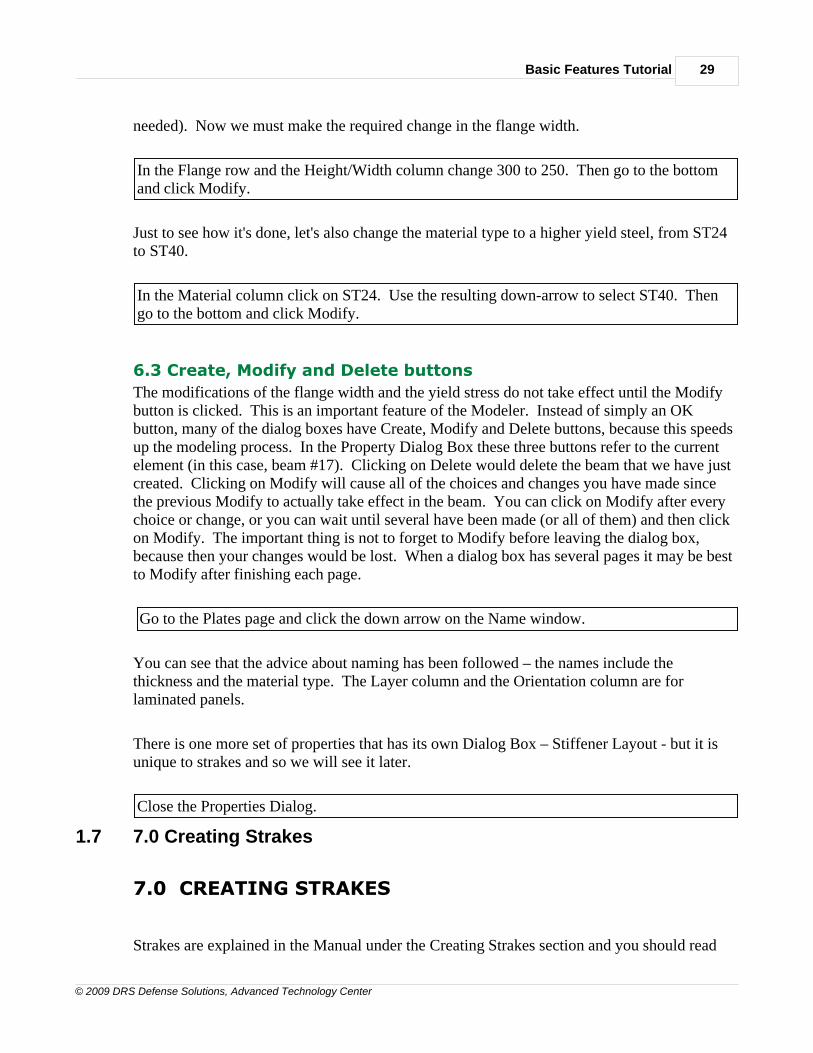
The list of materials is created using the Materials Dialog Box. You could get this via theMain Menu (Model > Materials) but it also has its own button in the Pre-Processing Toolbar
-
Click on the Materials button and then click the down arrow on the Name window.
The Materials Dialog Box is explained here, under Defining Materials & Properties, and youshould read this now. In our example six grades of steel have been defined. Two of these,ST24 and ST40, have been used for EX1. If we needed other materials, such as aluminum,we could define their properties using this dialog box.
MAESTRO Basic Features Tutorial28
© 2009 DRS Defense Solutions, Advanced Technology Center
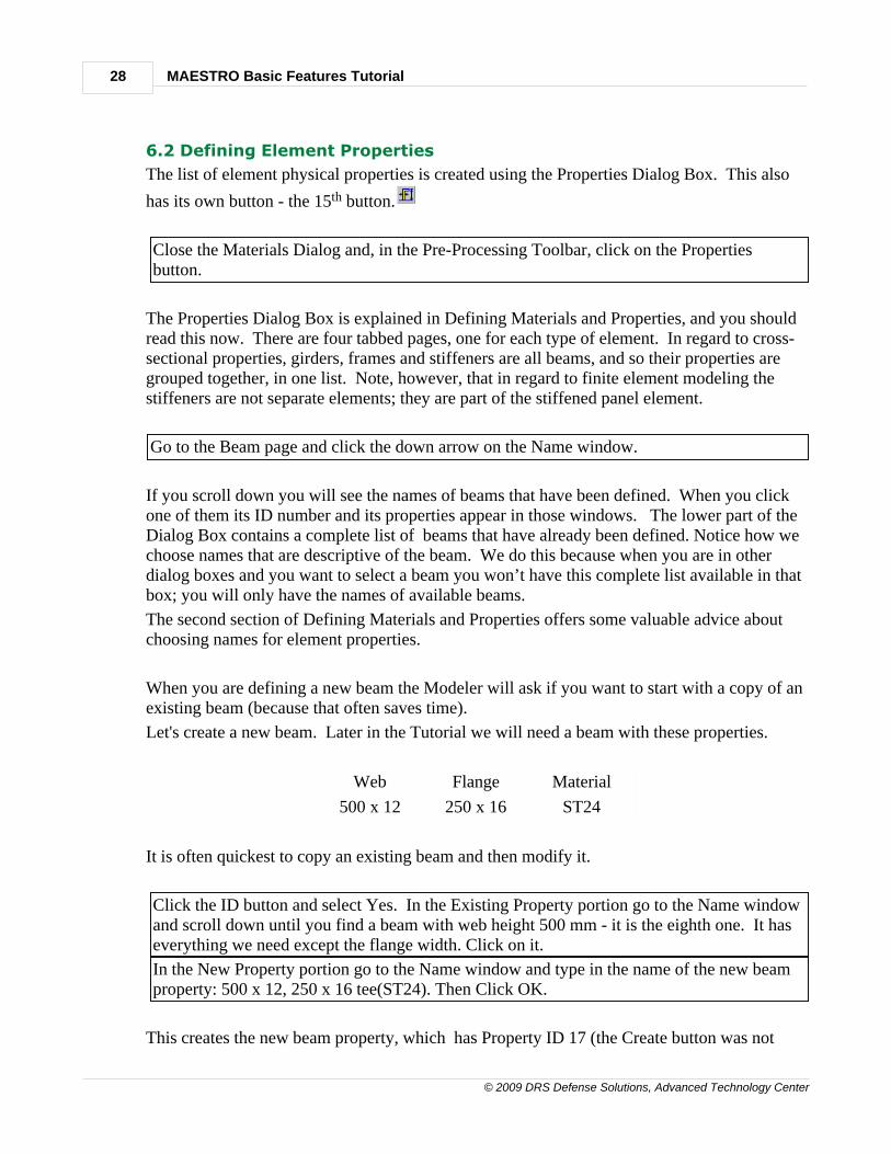
6.2 Defining Element Properties
The list of element physical properties is created using the Properties Dialog Box. This also
has its own button - the 15th button.
Close the Materials Dialog and, in the Pre-Processing Toolbar, click on the Propertiesbutton.
The Properties Dialog Box is explained in Defining Materials and Properties, and you shouldread this now. There are four tabbed pages, one for each type of element. In regard to cross-sectional properties, girders, frames and stiffeners are all beams, and so their properties aregrouped together, in one list. Note, however, that in regard to finite element modeling thestiffeners are not separate elements; they are part of the stiffened panel element.
Go to the Beam page and click the down arrow on the Name window.
If you scroll down you will see the names of beams that have been defined. When you clickone of them its ID number and its properties appear in those windows. The lower part of theDialog Box contains a complete list of beams that have already been defined. Notice how wechoose names that are descriptive of the beam. We do this because when you are in otherdialog boxes and you want to select a beam you won’t have this complete list available in thatbox; you will only have the names of available beams.
The second section of Defining Materials and Properties offers some valuable advice aboutchoosing names for element properties.
When you are defining a new beam the Modeler will ask if you want to start with a copy of anexisting beam (because that often saves time).
Let's create a new beam. Later in the Tutorial we will need a beam with these properties.
Web Flange Material
500 x 12 250 x 16 ST24
It is often quickest to copy an existing beam and then modify it.
Click the ID button and select Yes. In the Existing Property portion go to the Name windowand scroll down until you find a beam with web height 500 mm - it is the eighth one. It haseverything we need except the flange width. Click on it.
In the New Property portion go to the Name window and type in the name of the new beamproperty: 500 x 12, 250 x 16 tee(ST24). Then Click OK.
This creates the new beam property, which has Property ID 17 (the Create button was not
Basic Features Tutorial 29
© 2009 DRS Defense Solutions, Advanced Technology Center
needed). Now we must make the required change in the flange width.
In the Flange row and the Height/Width column change 300 to 250. Then go to the bottomand click Modify.
Just to see how it's done, let's also change the material type to a higher yield steel, from ST24to ST40.
In the Material column click on ST24. Use the resulting down-arrow to select ST40. Thengo to the bottom and click Modify.
6.3 Create, Modify and Delete buttons
The modifications of the flange width and the yield stress do not take effect until the Modifybutton is clicked. This is an important feature of the Modeler. Instead of simply an OKbutton, many of the dialog boxes have Create, Modify and Delete buttons, because this speedsup the modeling process. In the Property Dialog Box these three buttons refer to the currentelement (in this case, beam #17). Clicking on Delete would delete the beam that we have justcreated. Clicking on Modify will cause all of the choices and changes you have made sincethe previous Modify to actually take effect in the beam. You can click on Modify after everychoice or change, or you can wait until several have been made (or all of them) and then clickon Modify. The important thing is not to forget to Modify before leaving the dialog box,because then your changes would be lost. When a dialog box has several pages it may be bestto Modify after finishing each page.
Go to the Plates page and click the down arrow on the Name window.
You can see that the advice about naming has been followed – the names include thethickness and the material type. The Layer column and the Orientation column are forlaminated panels.
There is one more set of properties that has its own Dialog Box – Stiffener Layout - but it isunique to strakes and so we will see it later.
Close the Properties Dialog.
1.7 7.0 Creating Strakes
7.0 CREATING STRAKES
Strakes are explained in the Manual under the Creating Strakes section and you should read

MAESTRO Basic Features Tutorial30
© 2009 DRS Defense Solutions, Advanced Technology Center
that now.
The Strake Dialog Box is explained in Creating Strakes. That section is rather lengthy,because a strake is the most important and powerful modeling element within MAESTRO. Instead of reading it now, we will refer to specific parts of it as needed.
Strakes are located between end points, and so we will create the first two strakes of mod2,which will be located in between the end points we have already created.
Go to the Pre-Processing Toolbar and click on the Strake button (11th from the top).
7.1 Creating Strake 1
The first step in a creation sequence is always the same - get the next available ID number.
Click on the ID button.
The first strake lies between end points 1 and 2. As it happens, these numbers are already in

Basic Features Tutorial 31
© 2009 DRS Defense Solutions, Advanced Technology Center
the end point windows because MM does that for the first strake. But to get more practice atusing MM’s “shortcut”:
Put the cursor in each box and delete the numbers, using the keyboard Delete key.
Now execute the usual shortcut procedure.
Click on the ID button, click on the first end point window, move the cursor to end point 1and click on it.
(Note that you don’t have to click exactly on the end point; you can click anywhere along theline of nodes corresponding to that end point). Notice that the Modeler has placed a 1 in theEnd Point 1 box.
Now move to end point 2 and click on it. Within a module each strake must have a uniquename. In the Name box put, say, Strake 1, bottom shell.
We have seen that nearly everything is identified by an ID number. Also, to speed things up,many quantities have default values. In creating this first strake we will defer making somechoices until later, and so, for now, the Modeler will use the default values. The default valuefor a Property ID is 1; i.e. the first property that was defined. For example, for plating thefirst property is 9 mm plate made of ST24 steel, because that was the first type of plating tobe defined.
To see this, click on the Plating tab of the Strake Dialog Box
Now everything is defined, although only as defaults, so we can create the strake.
Click on Create.
The Modeler draws the panels of strake 1 to show that the strake exists, but bear in mind thatwe although we have created the strake, we have not yet defined its plating or stiffeners or anyother of its elements. We will do that now, using the appropriate tabbed pages.
Right now, since we have just started to define the strake, we are on the General page. Thevarious pages are explained in Creating Strakes. By default the Type is “Regular” and theLocation is “Bottom”.
Click the down arrow in the Location window.
MAESTRO Basic Features Tutorial32
© 2009 DRS Defense Solutions, Advanced Technology Center
The four possible locations are Bottom, Side, Deck and Other. The Location of a strake hasvery important consequences, especially for hydrostatic pressure loads. Read Step 4 of Creating Strakes to get the basic idea. Since we want strake 1 to receive pressure from theocean, make sure that the Location is Bottom. If it was part of the side shell, you would selectSide.
Select the Plating page and click on the down arrow in the Properties window.
For strake 1 we want 12 mm plating, because that is what mod1 has. So go ahead and selectthat property.
Click on the 12 mm plate name and then, to make a deliberate error, click on Create.
You get an error message because the strake has already been created, and the definition of itselements (plating, stiffeners, frames and girders) is considered as a modification of the strake.
Cancel the error message and click on Modify.
In the Strake Dialog Box the Create, Modify and Delete buttons refer to the strake as a whole.Clicking on Delete will delete the entire strake (and hence, for safety, MM will ask you toconfirm). Clicking on Modify will cause all of the choices and changes you have made sincethe previous Modify to actually take effect in the strake. You can click on Modify after everychoice or change, or you can wait until several have been made. When a dialog box hasseveral pages it may be best to Modify after finishing each page.
7.2 Stiffener LayoutSelect the Stiffeners page
Stiffeners have their own special Dialog Box called Stiffener Layout, and a special icon for
calling it up.
Here we don't need the icon because the Stiffeners page has a Layout button for calling it up.
Click on the Layout button
Each Stiffener Layout has a Name and an ID number. Earlier we chose (arbitrarily) Layout ID1, and we see here that its name is descriptive of its properties: 170x6, 100x10, b=400.
Stiffener Layout involves three choices:1. the Beam properties (sizes and material, defined using the Beam page of the Properties
Dialog Box)2. either the number of internal stiffeners, or the stiffener spacing3. Edge stiffeners, at either or both edges.

Basic Features Tutorial 33
© 2009 DRS Defense Solutions, Advanced Technology Center
For strake 1 we want Layout 3, because that is what mod1 has. Before any further discussionof Stiffener Layout, let’s define it for this strake.
Go back to the Stiffener page, click the down-arrow on the Layout window (or itsaccompanying ID window) select the third item, and then click Modify
If that was all we wanted to do, we would not have bothered calling up the Layout DialogBox. But let's say we want to see what three choices have been made for Layout 3. In thatcase we go back to the Layout Dialog Box and
Go to the Identification windows (either Name or ID) click the down-arrow and select thethird item.
This loads all of the windows with the choices that were made when Layout 3 was defined. The Name window has "Layout 3, 5 int. stiffeners". The Property window has "170x6,100x10, tee(ST40)", the Number of Internal Stiffeners is 5, and there are no Edge Stiffeners.
Since we have gone into the Layout Dialog Box we currently have the power to changeLayout 3 (or any other Layout) if we wanted to. But we would have to be sure about this,because this change would occur in all strakes that use Layout 3.
Before we close the Layout Dialog Box, let's discuss the meaning and purpose of "edgestiffeners".
7.3 Edge Stiffeners
Strake edges should always coincide with some longitudinal structure that provides at leastsimple support to those edges. This is very important, because the panel bucklingcalculations assume that the panel edges are at least simply supported. Thus, in EX1 the deckstrakes have either girders or side plating at their edges. Strakes 3 and 4 have a knuckle atend point 4, which is also "close enough" to simple support.
In the actual ship the plating of strakes 3 and 4 would be curved, not flat, and it is possible

MAESTRO Basic Features Tutorial34
© 2009 DRS Defense Solutions, Advanced Technology Center
that there could be a stiffener at end point 4. If so, then the "edge stiffener" option is a simpleway of allowing for the cross-sectional area of such a stiffener (and only the area; adding anedge stiffener has no other effect). A strake will always have either zero, one or two edgestiffeners. When choosing the number you should look at that strake only. In this example, ifwe want to place a stiffener at endpoint 4, then we would say that strakes 3 and 4 both haveone edge stiffener. MAESTRO automatically corrects for the apparent double counting.
Close the Stiffener Layout Dialog Box, go back to the Strake Dialog Box and click onModify.
7.4 Moving From Module to Module and Strake to Strake
At this point you may ask “What if I didn’t remember that strake 1 of mod1 has Layout 3? How can I find out?” This is part of a larger question: “How can I quickly jump from onemodule to another and, within a module, from strake to strake?”.
Here’s how (we have done this before, but it’s worth practicing because it’s very useful). Tochange to module mod1:
Click on the Set Current Part button and then click somewhere on module mod1 (notethat in the Parts Tree the "supporting hand" is now under the mod1 icon.
Now, whenever you want to refer to a strake or to change from one strake to another, youshould click in either the ID window or the Name window, and then click somewhere on thestrake that you want. It’s worth making a special effort to remember this step, becauseotherwise you will inadvertently begin working on a different strake from the one youintended, and the result will be both confusing and frustrating (because you may have to undoseveral changes).
Click in the ID window and then click somewhere on strake 1 in module mod1. Its name(bottom #1) appears in the window, confirming that it is now the active strake and all of itsproperties are available. Since we want Stiffener Layout, go to the Stiffeners page, and thereyou see the desired information – the Layout ID is indeed 3.
Note that the technique for selecting an existing strake is different from the shortcut that isused in creating a strake. To select a strake you click in the ID window, and then either on thestrake number (scrolling down if needed) or on the strake itself, in the model. To create a new strake you click on the ID button, which produces a new ID number, then you click in theEnd Point 1 window, and only then do you move the cursor to the displayed model and clickon the two end points.
Since we are dealing with stiffeners, let’s have the Modeler display them.
Click View Options, put a check mark on Stiffeners, then click OK.

Basic Features Tutorial 35
© 2009 DRS Defense Solutions, Advanced Technology Center
The name tells us that layout 3 involves 5 internal stiffeners (and so there are 5 red lines, butyou may have to spin the model to see them all). However, it does not tell us theirdimensions. To find those details we must go to the Layout Dialog Box.
Click on Layout.
The resulting Stiffener Layout Dialog Box tells us that the stiffeners are tee sections, the webis 170 x 6 mm, the flange is 100 x 10 mm, the material is high yield steel (ST40) and there are5 stiffeners. But we don’t need to remember all these numbers. It is enough to note that theID number of the layout is 3.
Close the Layout box and go to the Plating page.
The Plating page tells us that the plating is 12 mm high yield steel (ST40).
While we are here, we might as well find out what are the other properties of strake 1. We gonext to the Frame properties.
Go to the Frames page.
For use in module mod2 we note that for the frames the Property ID is 14 - a web height of400 mm and made of ordinary steel (ST24). The latter choice reflects the fact that the framesdo not carry the primary or hull girder bending load. If we later found the frames to be highlystressed due to transverse loads, we could define another Property ID, say 15, in which thematerial is a high yield steel.
Finally we look at the girder elements.
Go to the Girders page.
The Property ID is 13, which is a large tee section (web height 500 mm) made of high yieldsteel (ST40) because the girder elements do participate in hull girder bending.
In principle, we also need the properties of all the other strakes of mod1, and now would be agood time to get them and make a note of them. But to speed up the Tutorial we will do soonly for strake 2.
Click in the ID window and then click anywhere on strake 2 of module mod1. Its name(bottom #2) appears in the window, confirming that it is now the active strake. Go to thePlating page. This tells us that the thickness is again 12 mm. Go to the Stiffeners page.
MAESTRO Basic Features Tutorial36
© 2009 DRS Defense Solutions, Advanced Technology Center
This tells us that the ID of the stiffener layout is 4 (not 3, as in strake 1) and so in this regardstrake 2 is different from strake 1.
If you wanted details about layout 4 you could obtain them by clicking on the Layout button.(you would find that the stiffeners are smaller).
Go to the Frames page and note that the Property ID is 6. Go to the Girders page and notethat the Property ID is 2, with a web height of 350 mm instead of the 500 mm height inStrake 1.
We have now finished inspecting module mod1. We therefore return to module mod2 (whichmeans we make it the Current Part) and continue defining strake 1.
For practice, let's use the other method.
Go to the Parts Tree, right click on the mod2 icon and then click on Set Current Part.
Now we can finish strake 1 by defining its frame elements and its girder elements.
Click in the ID window , move the cursor over to the model and click on strake 1.
Its name (Strake 1, bottom shell) appears in the window, confirming that it is now the activestrake.
We now define the frame elements and the girder elements, using the ID numbers frommod1.
Go to the Frames page and set the Property ID to 14. Then go to the Girders page, click onEnable Girders and set the Property ID to 13. Click on Modify.
7.5 Creating Strakes by Copying Other Strakes and Modifying
The next task is to create strake 2 and define its elements. It is quite common to have similarstrakes within a module, and a very useful shortcut is to create a strake by copying anotherthat is similar and then making the needed changes (such as stiffener layout, which nearlyalways needs changing). But in the present case we have another type of similarity. We aredeliberately making mod2 be the same as mod1, and so we want to create the strakes of mod2by copying those of mod1. We will do this for strake 2, and then we will jump ahead toanother Modeler file for which all of the strakes have been copied.
Set mod1 to be the Current Part (from now on we will not call out every step for familiaractions) and then select strake 2.

Basic Features Tutorial 37
© 2009 DRS Defense Solutions, Advanced Technology Center
This loads all of the properties of strake 2 into the various windows of the strake pages (butthey will not actually be stored until the Create button is clicked). Now we want to set mod2as the Current Part, but we cannot do this in the usual way (clicking on Set Current Part andthen clicking on mod2) because the only place to click is within strake 1 and that wouldreplace all of the windows with the data of strake 1 of mod2. Therefore we use the other way– the Parts Tree.
Move the cursor to the Parts Tree. If necessary, expand the Tree by clicking the + signs. Then right click on mod2 and then click on Set Current Part.
Now that mod2 is the Current Part we are ready to create strake 2, whereupon all of the datafrom strake 2 of mod1 that is currently loaded into the various strake windows will beallocated to the new strake. If the new strake differed from the old strake 2 in some way wecould either make the changes now, or we could wait until the strake was created and thenModify it. In the present case there are no changes. Remember that to create a new strakeyou should click on the ID button, rather than the ID window, and then click Create.
Click on the ID button and then click Create.
We could repeat this copying operation for all of the rest of the strakes. However, to speed upthe Tutorial we will now change to another Modeler file, called EX1B.MDL, in which all ofthe other strakes have already been created.
Close the Strake page.
We are about to load a new Modeler file. This will cause MM to ask whether we first want tosave the changes we have made to file EX1A.MDL. Normally we would, but in this case wewant to leave the Modeler file unchanged, so that it is in the form that matches the beginningof this session of the Tutorial.
1.8 8.0 Deleting Elements
8.0 DELETING ELEMENTS TO REPRESENT OPENINGS –TUTORIAL ENTRY POINT 3
Click on the Open File icon (or click File/Open starting in the Main Menu) go to the Samplesfolder and then double click on file EX1B.MDL. If you are continuing from Chapter 7 youwill be asked about saving EX1A.MDL. Click on No. Since this is a small model, switch onthe stiffener display (View Options).
MAESTRO Basic Features Tutorial38
© 2009 DRS Defense Solutions, Advanced Technology Center
Note that the Status Bar (lower right of the screen) shows that the Current Part is mod2. When beginning to work on a module you should always check this.
In this new version of the model, mod2 has all of its strakes, but nothing else as yet. Thedeletion of some elements in strake 9, to create the uptake opening, has not been done and sowe begin with that.
MAESTRO has both coarse mesh and fine mesh modeling. The vertical Toolbar on the rightoffers graphics tools for subdividing coarse mesh elements so as to achieve a finer mesh. Since we are here doing only coarse mesh modeling
Go to Tools / Tool Bars / Refine Elements and toggle it off.
In coarse mesh modeling, for greater speed the elements of a strake are automaticallygenerated over the full length of the strake. Any large opening is then represented by deletingsome of the strake elements, while small openings are ignored. In our model the second deckhas a large opening – an uptake trunk – whereas the main deck has only small openings forindividual ducts, and these have been ignored.
Basic Features Tutorial 39
© 2009 DRS Defense Solutions, Advanced Technology Center
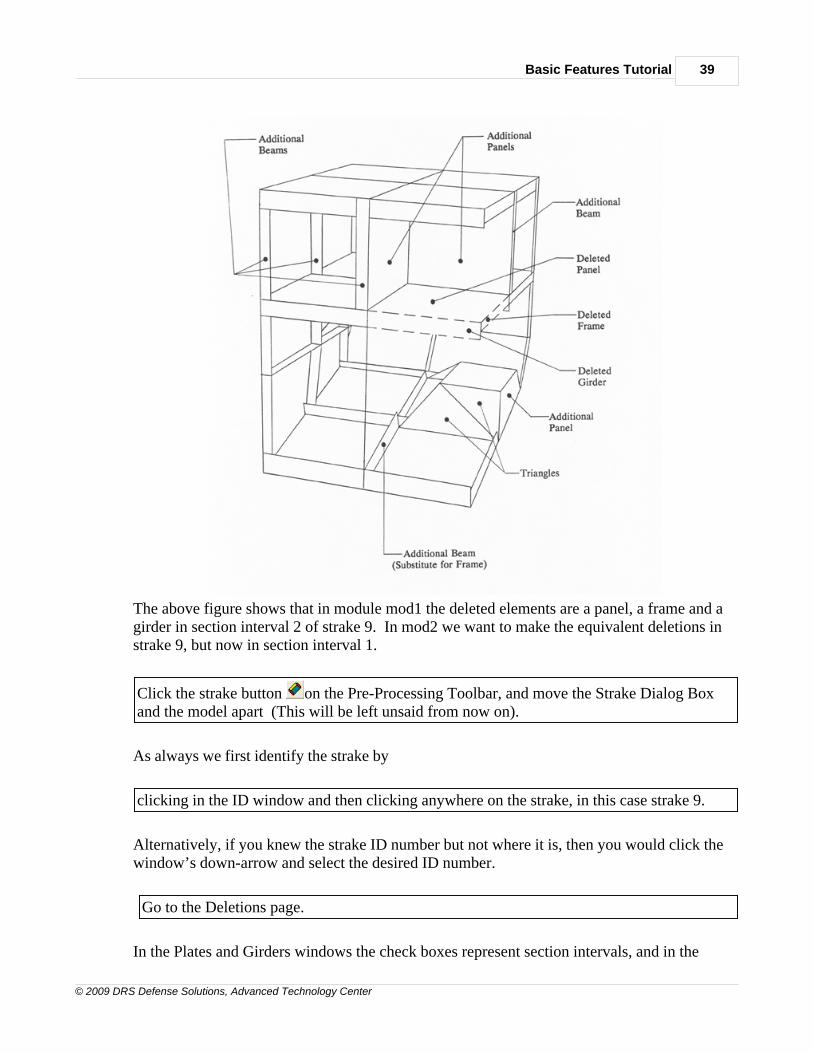
The above figure shows that in module mod1 the deleted elements are a panel, a frame and agirder in section interval 2 of strake 9. In mod2 we want to make the equivalent deletions instrake 9, but now in section interval 1.
Click the strake button on the Pre-Processing Toolbar, and move the Strake Dialog Boxand the model apart (This will be left unsaid from now on).
As always we first identify the strake by
clicking in the ID window and then clicking anywhere on the strake, in this case strake 9.
Alternatively, if you knew the strake ID number but not where it is, then you would click thewindow’s down-arrow and select the desired ID number.
Go to the Deletions page.
In the Plates and Girders windows the check boxes represent section intervals, and in the
MAESTRO Basic Features Tutorial40
© 2009 DRS Defense Solutions, Advanced Technology Center
Frames window they represent sections. In the Plates and Girders windows click on the checkbox labeled 1, and in the Frames window click on the box labeled 0. We have now requestedthree deletions. But as always with strake operations, they do not take effect until we
Click on Modify.
Note that we cannot delete elements using the Delete button because that would delete theentire strake.
If desired, deleted elements can be undeleted. You would simply click again on theappropriate check box(es), causing them to become empty, and then click on Modify.
There is a special Dialog Box that provides many ways to delete elements. In the
Pre-Processing Toolbar the icon is a scissors
Information about this is given in Deleting Elements.
1.9 9.0 Creating Additional Panel Elements
9.0 CREATING ADDITIONAL (I.E. NON-STRAKE) PANELELEMENTS
Beams and panels that are not part of a strake are referred to as “additional” beams andpanels. These and all other elements that are not part of a strake (triangles, rods, springs,brackets, etc.) must be created individually. In module mod1 the vertical walls of the uptaketrunk are made of two additional panels, and we will now create their counterparts in modulemod2.
Additional panels are also called quadrilaterals or “quads”. On the Pre-Processing Toolbar
the Quad button is . Click the button and then move the dialog box to the lower right. Inthe Manual Quadrilateral elements are explainedat the beginning of Creating AdditionalElements. Read through the eight steps for creating a “quad” element. The Connectivitysection of the Dialog Box defines the four nodes that make up the panel. Each panel isdefined by specifying the endpoint and section numbers of element nodes 1, 2, 3 and 4,moving around the element boundary. The starting point and the direction are arbitrary, butthey do determine the origin and the directions of the element axes, and the stiffenerorientation must be consistent with this: “edge 1” runs from node 1 to node 2, and “edge 3”runs from node 3 to node 4. Transverse stiffening runs from edge 1 to edge 3.
Let us first create the quad that is aligned in the longitudinal direction and We need to knowthe endpoint numbers that are in line with its lower and upper edges. One way to do this is to
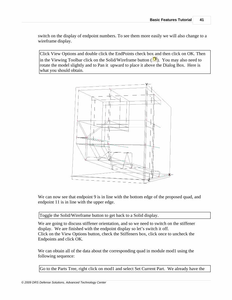
Basic Features Tutorial 41
© 2009 DRS Defense Solutions, Advanced Technology Center
switch on the display of endpoint numbers. To see them more easily we will also change to awireframe display.
Click View Options and double click the EndPoints check box and then click on OK. Then
in the Viewing Toolbar click on the Solid/Wireframe button ( ). You may also need torotate the model slightly and to Pan it upward to place it above the Dialog Box. Here iswhat you should obtain.
We can now see that endpoint 9 is in line with the bottom edge of the proposed quad, andendpoint 11 is in line with the upper edge.
Toggle the Solid/Wireframe button to get back to a Solid display.
We are going to discuss stiffener orientation, and so we need to switch on the stiffenerdisplay. We are finished with the endpoint display so let’s switch it off.Click on the View Options button, check the Stiffeners box, click once to uncheck theEndpoints and click OK.
We can obtain all of the data about the corresponding quad in module mod1 using thefollowing sequence:
Go to the Parts Tree, right click on mod1 and select Set Current Part. We already have the
MAESTRO Basic Features Tutorial42
© 2009 DRS Defense Solutions, Advanced Technology Center
Quad page and so we select the desired quad in the usual way, Click in the ID window andthen clicking on the quad itself.
This causes all of the data for this quad to appear in the windows of this page. We see thatthe Quad ID is 2, the Properties ID is 4, and the Stiffener Layout ID is 10, in which there are 3stiffeners and they run from edge 2 to edge 4 (i.e. longitudinally). But how do we know wherethe origin (node 1) is, and the direction of the node numbering? To tell us this the Modeleralways puts an arrowhead (a big open triangle) pointing to and touching node 2. To avoidclutter the shaft of the arrow is not drawn, but it always runs from node 1 to node 2. So nowwe know that node 1 is at the lower left corner of the quad and, from our prospective, thenodes are numbered in a counter-clockwise direction. We also know, from a right hand rule,that the normal for this quad element is pointing toward the ship’s centerplane. This becomesimportant when there is a pressure load on an element. From the node numbering, we nowalso know that Edge 1 is the lower edge (the shaft of the arrow) and so Edges 2 and 4 are theforward and aft edges. We see that the Direction window says “Edge 2 to Edge 4”, and so itis telling us that the stiffener direction is longitudinal. Since the stiffeners are being displayedwe can visually confirm this. The next figure shows what you should be seeing on yourscreen.
Now go back to mod2.
Go to the Parts Tree, right click on mod2 and select Set Current Part.
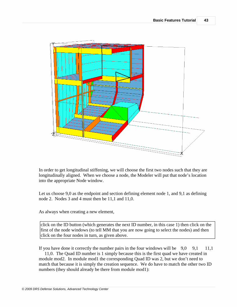
Basic Features Tutorial 43
© 2009 DRS Defense Solutions, Advanced Technology Center
In order to get longitudinal stiffening, we will choose the first two nodes such that they arelongitudinally aligned. When we choose a node, the Modeler will put that node’s locationinto the appropriate Node window.
Let us choose 9,0 as the endpoint and section defining element node 1, and 9,1 as definingnode 2. Nodes 3 and 4 must then be 11,1 and 11,0.
As always when creating a new element,
click on the ID button (which generates the next ID number, in this case 1) then click on thefirst of the node windows (to tell MM that you are now going to select the nodes) and thenclick on the four nodes in turn, as given above.
If you have done it correctly the number pairs in the four windows will be 9,0 9,1 11,1 11,0. The Quad ID number is 1 simply because this is the first quad we have created inmodule mod2. In module mod1 the corresponding Quad ID was 2, but we don’t need tomatch that because it is simply the creation sequence. We do have to match the other two IDnumbers (they should already be there from module mod1):

MAESTRO Basic Features Tutorial44
© 2009 DRS Defense Solutions, Advanced Technology Center
Make sure that 4 is shown for the Properties ID and 10 is shown for the Stiffener Layout, andthen
Click on Create.
The second additional panel lies in the section 1 transverse plane of the module. In order toget horizontal stiffening, we will choose the first two nodes such that they are horizontallyaligned. Let us choose 9,1 as the end point and section defining element node 1, and 8,1 asdefining node 2. Nodes 3 and 4 must then be 10,1 and 11,1. This quad is identical to the firstone and so the obvious course is to copy (i.e. leave the Property and Stiffener Layout IDnumbers as they are).
Click on the ID button (which generates ID number 2) click on the first of the node windows,then click on the four nodes in turn, as given above, and then click on Create.
If you have done it correctly the number pairs in the four windows will be 9,1 8,1 10,1 11,1.
Now go back to viewing the complete model.
Go to the Parts Tree, right click on sub1 and select Set View Part.
1.10 10.0 Creating Additional Beams
10.0 CREATING ADDITIONAL BEAM ELEMENTS–TUTORIAL ENTRY POINT 4
If you are entering the Tutorial at this point,
Click the Open Existing File icon and then double click EX1C.MDL. Make sure that theCurrent Part is mod2 (check for the "hand" under it in the Parts Tree).
If you are continuing from Chapter 9 there is no need because at this entry point there are nojumps in the modeling.
By definition all of the frame elements in a strake have the same “scantlings” (cross-sectionaldimensions and thicknesses). In module mod1 the frame element in strake 1, section 1, at thebase of the pillar, has been replaced by a larger beam because of the extra load caused by thepillar. We now want to create a similar replacement beam in module mod2. Actually, wehave already created it, back in Section 6.2 of the Tutorial, when we created a beam with thefollowing properties:
Basic Features Tutorial 45
© 2009 DRS Defense Solutions, Advanced Technology Center
Web Flange Material
500 x 12 250 x 16 ST24
We will do so again by copying and adapting an existing beam property (Property ID 8)following the same procedure as in Section 6.2. The new beam Property ID is 17.
Click on the Pre-Processing Toolbar icon for Beams (the I-beam icon).
This is not just any beam; it is meant to replace a specific frame element in strake 1 and so wemust tell that to the Modeler.
In the "Web Orientation" portion of the Dialog Box click on the check box for "ByAssociated Element." Then indicate which strake by selecting Strake in the Type window(it's already that by default) and then by selecting 1 in the Element ID window (it's alsoalready that by default).
Now choose the beam that we created earlier, with the properties shown in the above table.
Either scroll down the Property window until you find the desired scantlings (last line,because it was the latest one to be created) or scroll down the Property ID window to ID 17,and select it.
The bottom window, Web Orientation, is “grayed out” because for a replacement beam this isalways the same as the frame or girder element it is replacing.
Now we can create the element in the usual way.
Click on the ID button and then on the Node 1 window.
The next step is to click on the nodes themselves. Both nodes are at section 1, i.e. the samesection as the pillar (the new pillar, which has not yet been created). Since this is areplacement beam the nodes must be defined in the same order as the frame element it isreplacing. For illustration, choose the wrong order –
Click on the node at end point 2 first and then on the node at end point 1. Then click onCreate.
The error message explains what is wrong.

MAESTRO Basic Features Tutorial46
© 2009 DRS Defense Solutions, Advanced Technology Center
Cancel it, click again in the Node 1 window, and this time click on the nodes in the correctorder. Then click Create.
Since the beam replaces a strake-based beam, the “second flange” of the beam is the plating towhich it is attached. Here that plating is strake 1, for which the thickness is 12 mm, and sothe Modeler has automatically inserted 12. By default the width of a “plate flange” is taken as50% of the full width of the plating. Since this additional beam runs transversely, the widthof its plate flange is in the longitudinal direction; i.e. the full (100%) width of the plate flangeis the frame spacing, 2500 mm, and so the Modeler has specified 1250 as the width.
1.11 11.0 Creating Rod Elements
11.0 CREATING ROD ELEMENTS
We now create the pillar, using a rod element (we could use a beam element, and we shoulddo so if we want the member to have bending stiffness). Let’s say the pillar is to be a tube ofdiameter 150 mm, wall thickness 10 mm, material ST24, eccentricity coefficient a = 0.002(explained in Section 11.2 of Ship Structural Design) and effective length factor 0.5 (clampedends).
In the Pre-Processing Toolbar click the Rod Elements button , which brings you to theRods page. To see what properties have already been defined, click on the Properties button. The resulting Properties Dialog Box shows that one rod element has been defined as 150 ´10. Close the Properties Dialog Box and click the “down arrow” in the Property window,scroll down and select Rod Prop 1. (it's already there because we only have one rod.)
Now we can create the pillar.
Click on the ID button and then click in the Node 1 window. Go to the model and click onthe two nodes that are to be the top and bottom of the pillar. Then click Create.
1.12 12.0 Other Features
12.0 OTHER FEATURES OF THE MODELER – TUTORIALENTRY POINT 5
Click the Open Existing File icon and then double click EX1D.MDL. Do not save theprevious model.
This model includes the replacement beam and the pillar of Chapters 10 and 11. If you arecontinuing from Chapter 11 there is no need to change files because at this entry point there
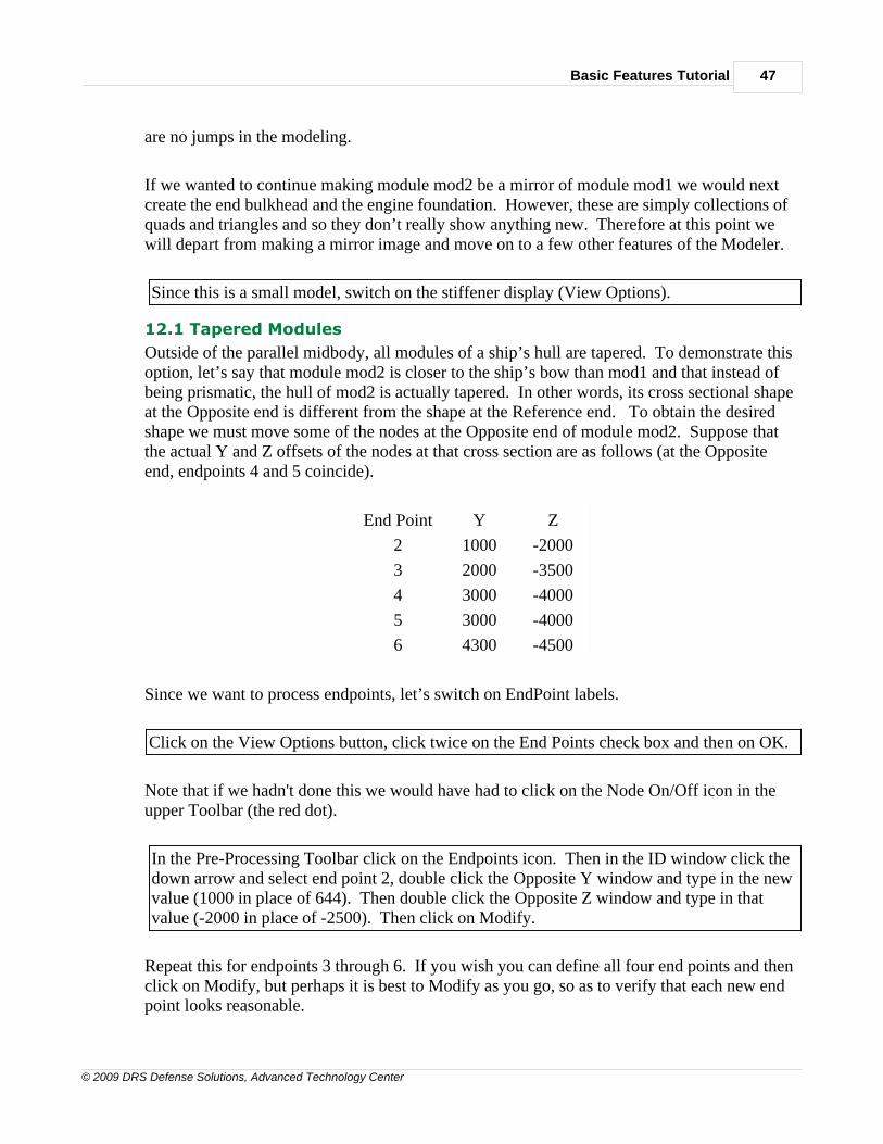
Basic Features Tutorial 47
© 2009 DRS Defense Solutions, Advanced Technology Center
are no jumps in the modeling.
If we wanted to continue making module mod2 be a mirror of module mod1 we would nextcreate the end bulkhead and the engine foundation. However, these are simply collections ofquads and triangles and so they don’t really show anything new. Therefore at this point wewill depart from making a mirror image and move on to a few other features of the Modeler.
Since this is a small model, switch on the stiffener display (View Options).
12.1 Tapered Modules
Outside of the parallel midbody, all modules of a ship’s hull are tapered. To demonstrate thisoption, let’s say that module mod2 is closer to the ship’s bow than mod1 and that instead ofbeing prismatic, the hull of mod2 is actually tapered. In other words, its cross sectional shapeat the Opposite end is different from the shape at the Reference end. To obtain the desiredshape we must move some of the nodes at the Opposite end of module mod2. Suppose thatthe actual Y and Z offsets of the nodes at that cross section are as follows (at the Oppositeend, endpoints 4 and 5 coincide).
End Point Y Z
2 1000 -2000
3 2000 -3500
4 3000 -4000
5 3000 -4000
6 4300 -4500
Since we want to process endpoints, let’s switch on EndPoint labels.
Click on the View Options button, click twice on the End Points check box and then on OK.
Note that if we hadn't done this we would have had to click on the Node On/Off icon in theupper Toolbar (the red dot).
In the Pre-Processing Toolbar click on the Endpoints icon. Then in the ID window click thedown arrow and select end point 2, double click the Opposite Y window and type in the newvalue (1000 in place of 644). Then double click the Opposite Z window and type in thatvalue (-2000 in place of -2500). Then click on Modify.
Repeat this for endpoints 3 through 6. If you wish you can define all four end points and thenclick on Modify, but perhaps it is best to Modify as you go, so as to verify that each new endpoint looks reasonable.
MAESTRO Basic Features Tutorial48
© 2009 DRS Defense Solutions, Advanced Technology Center
12.2 Compound ElementsCompounds are a means for quickly creating repetitive transverse structure, such as the largetransverse brackets in every frame of an oil tanker. In the Manual compounds are explainedin Creating Compounds. Since they are groups of elements, compounds are more complexthan any of the basic elements, and it is absolutely necessary to read the Manual before usingthem.
This tutorial does not include compounds. For interested users the triangular brackets in thebow of the fast ferry model (HighSpeedFerry.mdl) provide an example of a compoundelement.
1.13 13.0 Constraints, Loads, and Masses
13.0 CONSTRAINTS, LOADS AND MASSES – TUTORIALENTRY POINT 6
Click on the Open File icon (or click File > Open starting in the Main Menu) go to theSamples folder and then double click on file EX1E.MDL. If you are continuing fromChapter 12 you will be asked about saving EX1D.MDL. Click on No.
In the Pre-Processing Toolbar click on the Constraints button (a yellow triangle acting as a
fixed foundation). Drag the dialog box to the bottom and "pan" the model upwards, soyou can see both.
13.1 Constraints
When a model has such a large structure as a ship, it is usually advisable to test your model asif you built it; for example, after you have added each new substructure. This requires somefurther temporary data: constraints to prevent rigid body movement, some simple andidealized loads and, if any loads involve acceleration, the definition of masses. We have nowmodeled a complete compartment (the engine room) and so this is a good time to test themodel.
In order to move along quickly and to provide some examples, this further data (constraints,masses and loads) has already been entered into the current Modeler file, EX1E.MDL.
The Summary page summarizes the constraints, and the General page lists them.
Click on the tab for the General page.
You can get a visual display of the constraints from the Main Menu as follows.
Basic Features Tutorial 49
© 2009 DRS Defense Solutions, Advanced Technology Center
In the Main Menu click on View and then on Constraints.
You can now see three purple lines, representing the three constraints that are listed in theGeneral page. In order to see the lines more easily the model has changed to a wire-framepicture.
The View Constraints option, like many of the Modeler's display options, acts as a toggle. Tosee this, repeat the steps in the previous instruction two more times.
Click through View > Constraints.
The purple lines disappear.
Again click on through View > Constraints.
The purple lines reappear.
The bottom portion of the General page is a “List Box”, showing a list of the three constraintsthat have been defined. Since this model was declared to have port-starboard symmetry (way
back in the Job Information Dialog Box – the button at top left) the centerplaneconstraints are automatically supplied (no roll, sway or yaw). Since they are automatic theyare not displayed. Thus it was only necessary to impose three constraints to prevent the otherthree rigid body movements – heave, pitch and surge. These are two Y-constraints at theends, along the keel, and an X-constraint at the midlength of the model, located at a nodeclose to the hull girder neutral axis (so that the constraint does not interfere with hull girderbending). Let’s define one more constraint to see how it’s done, and then delete it.
Whenever you are dealing with a List Box for which the items are visible quantities (i.e. theycan be seen in the model) you can add items to the list by clicking on them in the model. Here the items are nodes, and so we must first
Click on the Nodes On/Off button in the Viewing Toolbar.
Now we can add nodes to the List by clicking directly on the nodes.
Click in the X check box at the upper left of the page. Then click anywhere within the ListBox to activate the cursor for the selection of a node. Then click on any node in the model.
You will see that the selected node is highlighted and it is added to the list as a fourth
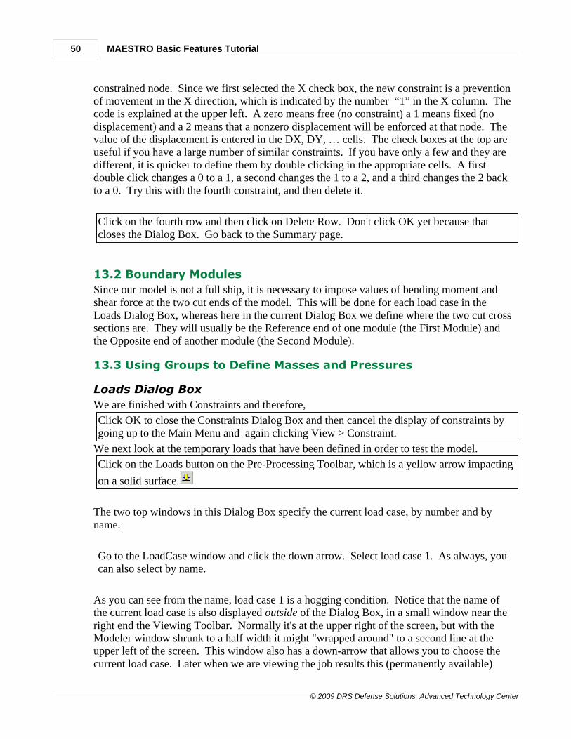
MAESTRO Basic Features Tutorial50
© 2009 DRS Defense Solutions, Advanced Technology Center
constrained node. Since we first selected the X check box, the new constraint is a preventionof movement in the X direction, which is indicated by the number “1” in the X column. Thecode is explained at the upper left. A zero means free (no constraint) a 1 means fixed (nodisplacement) and a 2 means that a nonzero displacement will be enforced at that node. Thevalue of the displacement is entered in the DX, DY, … cells. The check boxes at the top areuseful if you have a large number of similar constraints. If you have only a few and they aredifferent, it is quicker to define them by double clicking in the appropriate cells. A firstdouble click changes a 0 to a 1, a second changes the 1 to a 2, and a third changes the 2 backto a 0. Try this with the fourth constraint, and then delete it.
Click on the fourth row and then click on Delete Row. Don't click OK yet because thatcloses the Dialog Box. Go back to the Summary page.
13.2 Boundary Modules
Since our model is not a full ship, it is necessary to impose values of bending moment andshear force at the two cut ends of the model. This will be done for each load case in theLoads Dialog Box, whereas here in the current Dialog Box we define where the two cut crosssections are. They will usually be the Reference end of one module (the First Module) andthe Opposite end of another module (the Second Module).
13.3 Using Groups to Define Masses and Pressures
Loads Dialog Box
We are finished with Constraints and therefore,
Click OK to close the Constraints Dialog Box and then cancel the display of constraints bygoing up to the Main Menu and again clicking View > Constraint.
We next look at the temporary loads that have been defined in order to test the model.
Click on the Loads button on the Pre-Processing Toolbar, which is a yellow arrow impacting
on a solid surface.
The two top windows in this Dialog Box specify the current load case, by number and byname.
Go to the LoadCase window and click the down arrow. Select load case 1. As always, youcan also select by name.
As you can see from the name, load case 1 is a hogging condition. Notice that the name ofthe current load case is also displayed outside of the Dialog Box, in a small window near theright end the Viewing Toolbar. Normally it's at the upper right of the screen, but with theModeler window shrunk to a half width it might "wrapped around" to a second line at theupper left of the screen. This window also has a down-arrow that allows you to choose thecurrent load case. Later when we are viewing the job results this (permanently available)
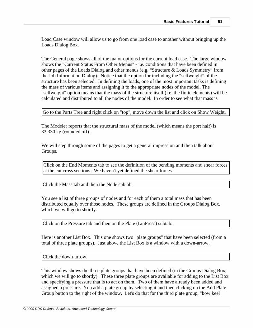
Basic Features Tutorial 51
© 2009 DRS Defense Solutions, Advanced Technology Center
Load Case window will allow us to go from one load case to another without bringing up theLoads Dialog Box.
The General page shows all of the major options for the current load case. The large windowshows the "Current Status From Other Menus" - i.e. conditions that have been defined inother pages of the Loads Dialog and other menus (e.g. “Structure & Loads Symmetry” fromthe Job Information Dialog). Notice that the option for including the “selfweight” of thestructure has been selected. In defining the loads, one of the most important tasks is definingthe mass of various items and assigning it to the appropriate nodes of the model. The"selfweight" option means that the mass of the structure itself (i.e. the finite elements) will becalculated and distributed to all the nodes of the model. In order to see what that mass is
Go to the Parts Tree and right click on "top", move down the list and click on Show Weight.
The Modeler reports that the structural mass of the model (which means the port half) is33,330 kg (rounded off).
We will step through some of the pages to get a general impression and then talk aboutGroups.
Click on the End Moments tab to see the definition of the bending moments and shear forcesat the cut cross sections. We haven't yet defined the shear forces.
Click the Mass tab and then the Node subtab.
You see a list of three groups of nodes and for each of them a total mass that has beendistributed equally over those nodes. These groups are defined in the Groups Dialog Box,which we will go to shortly.
Click on the Pressure tab and then on the Plate (LinPress) subtab.
Here is another List Box. This one shows two "plate groups" that have been selected (from atotal of three plate groups). Just above the List Box is a window with a down-arrow.
Click the down-arrow.
This window shows the three plate groups that have been defined (in the Groups Dialog Box,which we will go to shortly). These three plate groups are available for adding to the List Boxand specifying a pressure that is to act on them. Two of them have already been added andassigned a pressure. You add a plate group by selecting it and then clicking on the Add PlateGroup button to the right of the window. Let's do that for the third plate group, "bow keel

MAESTRO Basic Features Tutorial52
© 2009 DRS Defense Solutions, Advanced Technology Center
plating".
Select the third plate group and click on the Add Plate Group button.
The plate group is added to the list and, by default, is given the same pressure as the previousline (or row) in the list. If you really wanted to keep this third plate group in the list youwould now click on Modify , but we don't want it so
Click on the third line and then click on Del Row at the bottom.
Like the Nodal Groups these Plate Groups are defined in the Groups Dialog Box, so now is agood time to learn about the Groups Tree and the Groups Dialog Box. Then we will comeback to the Loads.
Close the Loads Dialog Box, move your cursor to the Parts and Groups Area (the verticalwindow at the far right, where the Parts Tree is) and at the bottom select Groups instead ofParts. If you can't see "Groups" click the little right-arrow. Expand all the + signs.
You are looking at the Groups Tree, which is a handy way of keeping track of all the variousgroups. The Groups Tree shows the three types of groups that are available, and we see thatthis model contains two Module Groups, three Node Groups and three Plate Groups. Like theParts Tree, the groups are arranged alphabetically within each type.
These groups are defined in the Groups Dialog Box, and the button for that is near the bottom
of the Pre-processing Toolbar, with a picture of three colored building blocks.
Groups Dialog Box
Click the Groups button. The Dialog Box is wider than we need so grab the right edge anddrag it to the left, but don't obscure the rightmost window. Move the Dialog Box down andpan the model up, so that you can see both. In the Dialog Box click the Module tab, then theID down arrow and then on 1.
Module Group
You should now see a window filled with lines. This is another List Box; in this case, a listof the modules that are in the current module group. Since the Modeler knows the volumeand density of all the finite elements in the model, it can easily calculate the total mass of theentire structure, and of any module within the structure. We saw earlier that the structure’sselfweight has already been included as part of the overall mass. There are other types ofmass that have a spatial distribution similar to that of the structure, and so they are usuallyrepresented as a scaled version of the structural mass. That is, the additional mass is dividedand allocated to the nodes in the same proportion as the structural mass. Some examples are
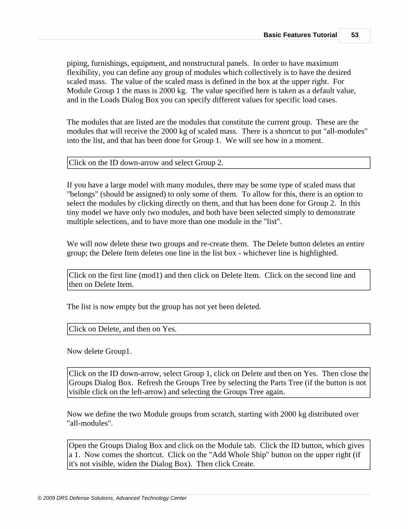
Basic Features Tutorial 53
© 2009 DRS Defense Solutions, Advanced Technology Center
piping, furnishings, equipment, and nonstructural panels. In order to have maximumflexibility, you can define any group of modules which collectively is to have the desiredscaled mass. The value of the scaled mass is defined in the box at the upper right. ForModule Group 1 the mass is 2000 kg. The value specified here is taken as a default value,and in the Loads Dialog Box you can specify different values for specific load cases.
The modules that are listed are the modules that constitute the current group. These are themodules that will receive the 2000 kg of scaled mass. There is a shortcut to put "all-modules"into the list, and that has been done for Group 1. We will see how in a moment.
Click on the ID down-arrow and select Group 2.
If you have a large model with many modules, there may be some type of scaled mass that"belongs" (should be assigned) to only some of them. To allow for this, there is an option toselect the modules by clicking directly on them, and that has been done for Group 2. In thistiny model we have only two modules, and both have been selected simply to demonstratemultiple selections, and to have more than one module in the "list".
We will now delete these two groups and re-create them. The Delete button deletes an entiregroup; the Delete Item deletes one line in the list box - whichever line is highlighted.
Click on the first line (mod1) and then click on Delete Item. Click on the second line andthen on Delete Item.
The list is now empty but the group has not yet been deleted.
Click on Delete, and then on Yes.
Now delete Group1.
Click on the ID down-arrow, select Group 1, click on Delete and then on Yes. Then close theGroups Dialog Box. Refresh the Groups Tree by selecting the Parts Tree (if the button is notvisible click on the left-arrow) and selecting the Groups Tree again.
Now we define the two Module groups from scratch, starting with 2000 kg distributed over"all-modules".
Open the Groups Dialog Box and click on the Module tab. Click the ID button, which givesa 1. Now comes the shortcut. Click on the "Add Whole Ship" button on the upper right (ifit's not visible, widen the Dialog Box). Then click Create.
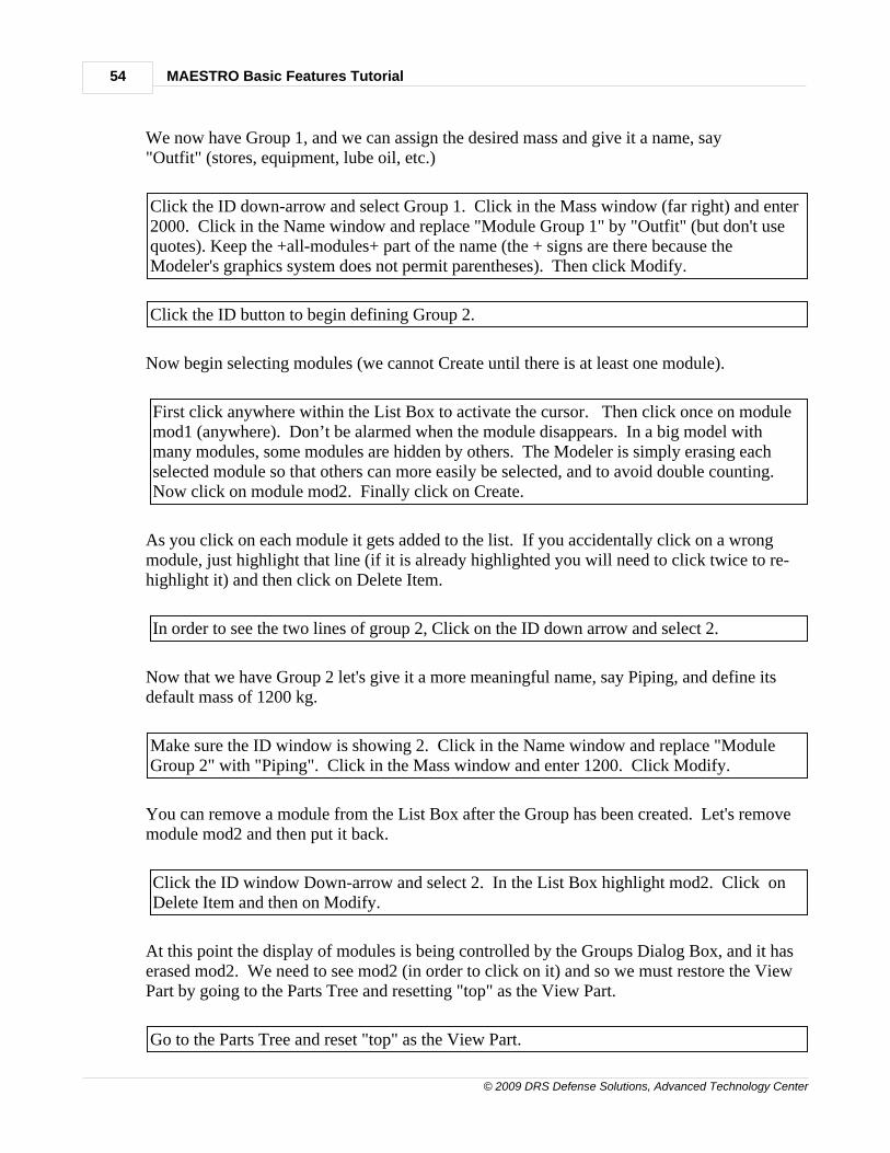
MAESTRO Basic Features Tutorial54
© 2009 DRS Defense Solutions, Advanced Technology Center
We now have Group 1, and we can assign the desired mass and give it a name, say"Outfit" (stores, equipment, lube oil, etc.)
Click the ID down-arrow and select Group 1. Click in the Mass window (far right) and enter2000. Click in the Name window and replace "Module Group 1" by "Outfit" (but don't usequotes). Keep the +all-modules+ part of the name (the + signs are there because theModeler's graphics system does not permit parentheses). Then click Modify.
Click the ID button to begin defining Group 2.
Now begin selecting modules (we cannot Create until there is at least one module).
First click anywhere within the List Box to activate the cursor. Then click once on modulemod1 (anywhere). Don’t be alarmed when the module disappears. In a big model withmany modules, some modules are hidden by others. The Modeler is simply erasing eachselected module so that others can more easily be selected, and to avoid double counting. Now click on module mod2. Finally click on Create.
As you click on each module it gets added to the list. If you accidentally click on a wrongmodule, just highlight that line (if it is already highlighted you will need to click twice to re-highlight it) and then click on Delete Item.
In order to see the two lines of group 2, Click on the ID down arrow and select 2.
Now that we have Group 2 let's give it a more meaningful name, say Piping, and define itsdefault mass of 1200 kg.
Make sure the ID window is showing 2. Click in the Name window and replace "ModuleGroup 2" with "Piping". Click in the Mass window and enter 1200. Click Modify.
You can remove a module from the List Box after the Group has been created. Let's removemodule mod2 and then put it back.
Click the ID window Down-arrow and select 2. In the List Box highlight mod2. Click onDelete Item and then on Modify.
At this point the display of modules is being controlled by the Groups Dialog Box, and it haserased mod2. We need to see mod2 (in order to click on it) and so we must restore the ViewPart by going to the Parts Tree and resetting "top" as the View Part.
Go to the Parts Tree and reset "top" as the View Part.

Basic Features Tutorial 55
© 2009 DRS Defense Solutions, Advanced Technology Center
Now restore mod2.
Click anywhere within the List Box to activate the cursor. Then click once on module mod2and then on Modify.
Here again the display of modules is being controlled by the Groups Dialog Box, and to bringback the usual view of the model you must either go to the Parts Tree and reset "top" as theView Part, or close the Dialog Box.
Go to the Parts Tree and reset "top" as the View Part, or close the Dialog Box and thenreopen it.
Node Group
You can also define a specific group of nodes that are to share a total mass, to be specified inthe Loads Dialog Box.
Switch over from the Parts Tree to the Groups Tree.
In the Groups Tree you can see that three such node groups have been defined, called “auxmachinery”, “gas turbine” and “superstructure”. As noted earlier, they are listedalphabetically, not in their ID order. You can display these on their own or in the context ofthe model.
Right click on aux machinery and then select “Context, User Defined Color”. If all of thered (finite element) nodes are being displayed you can get rid of them by clicking on theNodes, On/Off button (the big red dot).
You now see a wire-frame picture showing the three nodes of this group as small green dots.They are are on the ship's bottom, in line with endpoint 2. This group of nodes was defined onanother page of the Groups Dialog Box, under the Node tab.
Click on the Node tab, then the Name down-arrow to see the names of the three NodeGroups that have been defined. Click on aux machinery.
The red nodes appear because if we are going to select or deselect some nodes they have to bevisible.
Here is another List Box. Each line defines one node of the group. The first column has themodule name, the second column the type of node, and the third column the node ID number.
MAESTRO Basic Features Tutorial56
© 2009 DRS Defense Solutions, Advanced Technology Center
The first column probably needs to be widened so that the full name is visible. If so, do thisnow. The three nodes have the type “End Sect. Node” because they are defined by giving theirendpoint number and section number. Two of them have the ID 2,1 because they are both atendpoint 2, section 1 of their respective modules. The total mass distributed among thesenodes (defined as 5000 kg in the box at upper right) is representing some auxiliary machinery.
You can add and delete nodes to this list in the same way as you added and deleted modulesto the Modules List Box – click once in the List Box - you would to activate the cursor andthen click on each node that you want to add.
As mentioned above, the Modeler has automatically switched on the Display Nodes option,whereby all endpoint-generated nodes appear as red dots and all additional nodes appear asblue asterisks (the four nodes at the top corners of the machinery foundation). Whenever youwant to select nodes this option must be active. If you ever find that the Modeler is refusingto recognize node selection, check to see if this option has somehow not been activated.
If you know your model very well you could probably do the clicking in this wire-framedisplay.
Click in the List Box and then on some nodes in the model. Observe them being added tothe list.
However, in a big model it might be better to change to the usual solid (and colored) display. Since the Parts Tree is not presently visible, do this another way:
Go to the Main Menu, click on View, and then on Element Type.
For variety, select one of the four additional nodes (the blue asterisks at the top of themachinery foundation) and observe it being added to the list. Then, since we really don’twant these extra nodes, go to the List Box, highlight them (hold down the control key to getthem all) and then click on Del Item. (Actually, as long as you don’t click Modify, the extranodes would be dropped from the list when you closed this Dialog Box).
Let’s look at the other two node groups
Click on the ID down arrow and then on 1.
Here are three nodes for which a mass of 9600 kg has been assigned, to represent a gasturbine. To see their location in the context of the full model
In the Groups Tree right click on “gas turbine” and then select “Context, User Defined
Basic Features Tutorial 57
© 2009 DRS Defense Solutions, Advanced Technology Center
Color”.
This group has been colored yellow, to distinguish it from the first group. (one of the threenodes, the middle one, is obscured by the red finite element nodes because this is a jointbetween two modules).
There is a third group of mass nodes in the main deck, to simulate superstructure that is notbeing modeled. To get the list of nodes:
Go back to the Dialog Box, click on the ID down arrow and then on 3. At the bottom of theBox you can see that for this group the color pink has been selected. To get a display ofthese pink mass nodes:
Go to the Groups Tree, right click on “superstructure” and then select “Context, UserDefined Color”.
You can see the pink nodes in the main deck, where the side of a deckhouse would connect tothe main deck.
Plate Group
As can be seen in the Groups Tree, this model also contains three Plate Groups. These areused to specify a group of plate elements (quadrilaterals and triangles). In this case they arethe two decks and part of the bottom, and we saw earlier that these plate groups are usedwhen defining the pressure loads.
Close the Groups Dialog Box, go to the Groups Tree, right click on “plate” and then select“Context, User Defined Color”.
These three Plate Groups were defined in the Groups Dialog Box. The green plating in themain deck will be subjected to a pressure, simulating "green seas" on the deck. Note that theinboard strakes are not included because there is an unmodeled superstructure protectingthem. The yellow plating in the second deck will be used to define an area-related mass,representing live loads (furniture, personnel, etc.). The red plating on the bottom is an areathat will be subjected to a slamming pressure in one of the load cases.
To see the list of plate elements in the "main deck" group
Again bring up the Groups Dialog Box, move it so that the model is visible, click on thePlate tab, click on the Name down-arrow and then on "main deck".
Here the List Box contains two lines, defining the outboard deck strake (strake 8) in mod1and mod2. From the model display you can see that each line has defined two plate elements. This is because the Full Strake check box is checked, and in both modules the strakes are two

MAESTRO Basic Features Tutorial58
© 2009 DRS Defense Solutions, Advanced Technology Center
section intervals (two plate elements) in length.
You can add and delete plate elements to this list in the same way as you added and deletedmodules, by clicking once in the List Box and then on the desired plate elements. However,you should first change the model display from Wireframe to solid because then the Modelerwill erase each plate as you select it, which helps to verify the selection.
Let's practice this by deleting and then recreating the "bow keel plating" plate group.
Click on the Name down-arrow, then on "bow keel plating", then on Delete and then on Yes.
We now want to get a Solid display of the model, so that we can observe the erasing of eachplate as we select it.
Go to the Main Menu at the top, click on View and then on Element Type.
If that didn't work it is because the Groups Dialog Box has control of the display (from theright click and Context view that we did). In that case
Close the Groups Dialog Box. Click again on Main Menu / View / Element Type. Thenreopen the Groups Dialog Box and go to the Plate page.
Now we will define the "bow keel plating" plate group.
Go back to the Dialog Box, Click the ID button to get the next ID number (3) put a checkmark in the "Full Strake/Full Compound" check box, click once in the List Box, click on aplate element in the lowest strake in the forward module (mod2) .
You see that with one click the Modeler has erased two plate elements. This is because theFull Strake check box is checked.
Click on Create.
Let's now give this plate group a name and a color.
Click on the ID down-arrow, then on 3. Click in the Name window and enter bow keelplating. Click the Color down-arrow and select red. Click Modify.
The Modeler now displays the plate elements of this group, in case we wanted to work on it(e.
Basic Features Tutorial 59
© 2009 DRS Defense Solutions, Advanced Technology Center
g. define a pressure). For now, we will go back to the full model.
Close the Groups Dialog Box. Go to the Parts Tree and right click on top and then on SetView Part.
1.14 14.0 Defining Loads
14.0 DEFINING LOADS - TUTORIAL ENTRY POINT 7
At this point, whether you are continuing from Chapter 13 or entering you should
Click the Open File icon and double click on EX1F.MDL.
14.1 Loads Arising From Mass Times Gravity and Other Accelerations
We will first look at load case 1, which has several mass-related loads and a hogging wave. Load case 2 is a stillwater condition which we will use to explain how the ship is positionedrelative to the ocean surface. Then we'll define load case 3 by copying load case 1 andmaking changes, such as changing to a sagging wave.
Open the Loads Dialog Box, click the Load Case down-arrow and select 1. Click the Masstab, and then the Module subtab.
Now we will see how to use the groups we have defined. First we will use the all-modulesgroup and the Mass/Module page of the Dialog Box to allocate a total of 2000 kg of massamong all the nodes of both modules, in the same proportion as the structural (finite element)mass. Since this has already been done, let’s undo it and then redo it.
Highlight the outfit+all-modules+ row in the List Box and click on Del Row and then onModify.
The window above the List Box contains the available module groups (note that the ModuleGroup called outfit+all-modules+ is still available; we only deleted it from this List Box). Justto the right there is an Add button on the right.
In this window click the down-arrow and select the all-modules group. Then click the Addbutton and see that the group is added to the list. Most importantly, click on Modify or elseyour work will be lost.
We also defined three nodal groups as a way of allocating mass to a few specific nodes.
MAESTRO Basic Features Tutorial60
© 2009 DRS Defense Solutions, Advanced Technology Center
Click on the Node subtab.
You see that the three groups are already in the list, but if they weren’t we would click thedown arrow, select one of them and click on Add. It’s the same operation as for the ModuleGroup. We could also change the value of any of the masses by double clicking the currentvalue and typing a new value.
14.2 Loads Due to Explicitly Defined Pressures
We also defined three plate groups: "main deck", "2nd deck", and "bow keel plating", in orderto apply pressure to these groups.
Click on the Pressure tab, and then on the Plate (LinPress) subtab.
Two groups are already in the list, but if they weren’t we would perform the usual operation:click the down arrow, select one of them and click on Add Plate Group. The "bow keelplating" is not in the list because it is intended to simulate a slamming load, and that does notoccur in a hogging load case. (We are pretending that module mod2 is at or near the bow).
14.3 Loads Due to Stillwater and Wave Pressures
For instructional purposes Load Case 2 is a simple "stillwater" case, with no wave.
Click on the Load Case down-arrow and select 2.
The stillwater and wave loads are defined in the Balance page of the Loads Dialog Box. Inorder to “see” the ocean surface
Go to the Viewing Toolbar click the View Options button , select Water Plane and click
OK. Then go to the Solid/Wireframe button , and click on it.
The picture you have is like the following figure, but it includes the X, Y and Z axes. Theseare the Structure axes, and they are fixed to the ship.
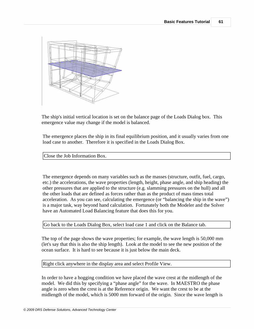
Basic Features Tutorial 61
© 2009 DRS Defense Solutions, Advanced Technology Center
The ship's initial vertical location is set on the balance page of the Loads Dialog box. Thisemergence value may change if the model is balanced.
The emergence places the ship in its final equilibrium position, and it usually varies from oneload case to another. Therefore it is specified in the Loads Dialog Box.
Close the Job Information Box.
The emergence depends on many variables such as the masses (structure, outfit, fuel, cargo,etc.) the accelerations, the wave properties (length, height, phase angle, and ship heading) theother pressures that are applied to the structure (e.g. slamming pressures on the hull) and allthe other loads that are defined as forces rather than as the product of mass times totalacceleration. As you can see, calculating the emergence (or “balancing the ship in the wave”)is a major task, way beyond hand calculation. Fortunately both the Modeler and the Solverhave an Automated Load Balancing feature that does this for you.
Go back to the Loads Dialog Box, select load case 1 and click on the Balance tab.
The top of the page shows the wave properties; for example, the wave length is 50,000 mm(let's say that this is also the ship length). Look at the model to see the new position of theocean surface. It is hard to see because it is just below the main deck.
Right click anywhere in the display area and select Profile View.
In order to have a hogging condition we have placed the wave crest at the midlength of themodel. We did this by specifying a “phase angle” for the wave. In MAESTRO the phaseangle is zero when the crest is at the Reference origin. We want the crest to be at themidlength of the model, which is 5000 mm forward of the origin. Since the wave length is

MAESTRO Basic Features Tutorial62
© 2009 DRS Defense Solutions, Advanced Technology Center
50,000 mm the phase angle is
Phase Angle = 360° ( 5000 / 50,000 ) = 36°
and that is why the “Phase A.” box has 36 in it.
Relative to the model the ocean surface is now much higher (at the midlength it is 2500 mmhigher) and it is slightly curved, being a crest.
14.4 Copying and Modifying a Load Case
We'll now make Load Case 3 by copying Load Case 1 and changing to a sagging wave.
Click on the Load Case button and select Yes. Replace the default name with STATICLOAD + SAGGING WAVE. In the "Existing Load Case" window click the down-arrow andselect 1. Then click OK.
We are still on the Balance page, so we are ready to change to a sagging wave. The phaseangle is zero when the crest is at the Reference origin, and the phase angle is 180° when thetrough is at the Reference origin. For sagging we want a trough to be at the midlength of themodel, which is 5000 mm forward of the origin. Since the wave length is 50,000 mm thephase angle is
Phase Angle = 180° + 360°( 5000 / 50,000 ) = 216°
In the “Phase A.” box change 36 to 216 and click Modify.
The display changes to Load Case 3 and if you look closely you will see the profile of thewave trough. It becomes more visible if you
right click anywhere in the display area and select Southeast.
In order to leave this Modeler file (EX1F.MDL) as it was, we need to delete this third loadcase.
Click on Delete and then close the Loads Dialog Box.
1.15 15.0 Quick Construction
15.0 QUICK CREATION - TUTORIAL ENTRY POINT 8

Basic Features Tutorial 63
© 2009 DRS Defense Solutions, Advanced Technology Center
If you are continuing from Chapter 14 do nothing - you already have the correct file. If youare entering at this point you should
click the Open File icon and double click on EX1F.MDL.
15.1 Adding a Bulkhead
In the actual ship the engine room has a transverse bulkhead at each end. Our model is not yetstructurally sound because it does not have the transverse bulkhead at the near end, similar tothe one at the far end. In order to simulate the load that this compartment would be receivingwhen it is part of the full ship, we are going to apply a bending moment and shear force ateach end of the model. If we do not provide the second bulkhead the model will not be strongenough to absorb these quite severe loads.
Let's examine the existing bulkhead to see what plating and beams were used. The bulkheadis not made of strakes (for that to be possible it would need to be a separate module, with itsX-axis pointing either upwards or transversely). Rather it is made from individualquadrilateral panel elements ("quads") and individual beam elements. Since we want tocreate a similar bulkhead at the near end of the model, we need to see what are the propertiesof these quads and beams.
15.1.1 Dialog Boxes for Elements and for Properties
There are two separate dialog boxes for defining elements and properties. Individualelements (quads, beams, springs, etc.) are defined on separate pages of the Finite ElementsDialog Box, and each element has a unique ID number. The properties that can be assigned toelements are defined on separate pages of the Properties Dialog Box. Each combination ofproperties that is defined (e.g. for a plate it would be material and thickness) is given aProperty ID Number and is added to a Property List for that element type. We need to findout what "Property ID Number" was used for these quads and beams.
Make sure that module mod1 is the Current Part. Then click on the Quad Elements button
click in the ID window and then click on one of the bulkhead panels, say the lowestinboard panel.
This is the Quad page of the Finite Elements Dialog Box. The ID number of the quad youclicked on is 7, and in the Property window we see that the thickness is 9 mm. In the IDwindow to the right we see that the Property ID is 1. That's all we need, because all of thebulkhead quads are the same material type and the same thickness - that is, the Property ID is1 for all of them.
Note that when we are talking about an element we use the word "quad", and when we aretalking about a property we use the word "plate". This is because plate properties pertain toboth quad elements and triangle elements.
MAESTRO Basic Features Tutorial64
© 2009 DRS Defense Solutions, Advanced Technology Center
Let's see what plate properties have been defined for quad elements.
Click the down-arrow in the Property window.
We see that four plate properties have been defined.
Notice that the Property button is a "clickable" button. If we wanted a thickness that was notone of the four available thicknesses, we would click this button, which takes us to the Platepage of the Properties Dialog Box.
Click on the button labeled Property.
The upper large window has just one line and it contains the properties of the "current" plate(or beam or rod or spring). For a solid plate there is only one "layer" and there are only twoproperties - material and thickness. For a laminated plate there is a separate line for eachlayer and three properties per layer. The lower large window is the Property List - the list ofall the different plate properties that have been defined. Four plate properties have beendefined, and they are distinct by virtue of their thickness. If we wanted one or more quads thathad some different combination of material and thickness we would define that combinationin the upper window, and when we clicked on Create it would be added to the Property List inthe lower window.
Close the Properties Dialog Box.
Now we need to see what type of beam was used for stiffening the bulkhead. We alreadyhave the Finite Elements Dialog Box open, so all we need to do is click the Beam tab. If itwere not open we could get it, with that page showing, by clicking the Beam Elements button
.
Click on the Beam tab, click in the ID window and then click on one of the bulkhead beams,say the lowest one on the centerline.
The ID of that beam is 1, and the Property ID is 5. If we looked at the other beams we wouldfind them all the same. So we now have all we need: the quads use Plate Property 1 and thebeams use Beam Property 5.
Close the dialog box.
15.1.2 Adding Endpoints for the New Bulkhead
The existing bulkhead extends over the entire transverse plane. In order to insert enoughelements to cover this expanse, the nodes in the shell and decks were not sufficient. Four

Basic Features Tutorial 65
© 2009 DRS Defense Solutions, Advanced Technology Center
more endpoints were defined. To see which endpoints these are, do the following.
Click the View Options button and click twice on Endpoints and then on OK, in order to
display endpoint labels. In order to see them better, toggle (click) the Wire Frame button
The endpoints that are used for the bulkhead are labeled 12, 13, 14 and 15 (you may need tozoom to find them). We need to define similar endpoints in module mod2, so we must makethat module be the Current Part. For better visibility let's also make it the View Part.
Toggle the Wire Frame button back to Solid. In the Parts Tree, right-click mod2 and make itthe Current Part, and then also make it the View Part.
You can see that one such endpoint - label 12 - has already been defined. Here is a picture ofthe five quads and two triangles that we intend to create, showing the existing endpoint (12)and one more that we will add (13).
Click on the Endpoint button click the down-arrow and select endpoint 12.
You see that it is at a height Y = 2000. Let's put another endpoint at the same height anddirectly above endpoint 2 in the ship's bottom, which in the plane of the bulkhead (theOpposite plane) is at Z = -2000.
Click the ID button to get the next available number (13) and enter -2000 as the Z value forboth Reference and Opposite planes and click Create.
Now we can begin creating the five quadrilaterals and two triangles that make up the

MAESTRO Basic Features Tutorial66
© 2009 DRS Defense Solutions, Advanced Technology Center
bulkhead.
15.2 Quick Creation of Quad Elements
This is an opportunity to use the "Quick Element Creation" option, for which the button is in
the upper toolbar, having the icon of a running man and a down-arrow . This optionallows you to create endpoints, additional nodes, strakes, quads, triangles, bars, rods, springs,and compounds very quickly, without going back and forth between the model and a dialogbox. We will demonstrate it for quads, since we need five of them. Also, since we're going totalking about stiffener layout, let's display the stiffeners.
Click View Options, then Stiffeners then OK.
You create the first quad in the usual manner, using the Quad dialog box. This serves as a"prototype" for the others and defines all their properties except for their node locations. Ifthere is a quad that is similar to what you want, choose it as the prototype, modify it asneeded, and create it. Let's choose the existing quad that forms the uptake trunk, changing itfrom 8 mm plating to 9 mm (to match the existing bulkhead).
Click the Quad button click in the ID window, move to the model and click on the uptaketrunk quad (ID number 2), which loads its properties into the dialog box. Click the ID buttonto get the next number (3). Click the down-arrow in the Property window and select "9 mmplate (ST24)".
In the Layout window the current choice is "Layout 10, 3 int. (internal) stiffeners". From theabove figure we see that the new quads are going to have different widths, and so instead of afixed number of stiffeners let's choose a fixed stiffener spacing.
In the Layout window click the down-arrow and scroll up to the first layout "Layout 1,170×6, 100×10, b=400" and select it.
If the layout you wanted was not available you would click the Layout button to get theStiffener Layout Dialog Box, define the desired layout, and then come back here and use it.
The Direction window tells us that the stiffener direction is "Edge 2 to Edge 4" (see Section3.8.2.1 Section 3.8.2.2 of Creating Additional Elements). The big arrowhead in the elementhighlighting tells us that node 1 is at the upper right and that node 2 is at the upper left, at theship's centerline. Bulkhead stiffeners are usually vertical, and we will get this for our newquad if we choose node 1 at the keel and node 2 directly above it, as shown in the figurebelow (nodes 1 and 2 in quad 3).
Click in the Node 1 window and then go to the model and click successively on the keelnode, the node above it (in line with endpoint 12) the node at the right (in line with endpoint13) and the node below that. Then click on Create.
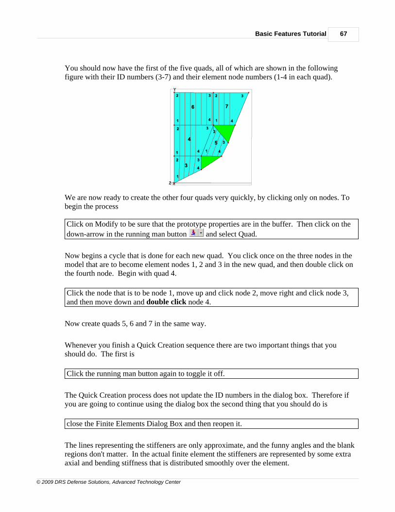
Basic Features Tutorial 67
© 2009 DRS Defense Solutions, Advanced Technology Center
You should now have the first of the five quads, all of which are shown in the followingfigure with their ID numbers (3-7) and their element node numbers (1-4 in each quad).
We are now ready to create the other four quads very quickly, by clicking only on nodes. Tobegin the process Click on Modify to be sure that the prototype properties are in the buffer. Then click on the
down-arrow in the running man button and select Quad.
Now begins a cycle that is done for each new quad. You click once on the three nodes in themodel that are to become element nodes 1, 2 and 3 in the new quad, and then double click onthe fourth node. Begin with quad 4.
Click the node that is to be node 1, move up and click node 2, move right and click node 3,and then move down and double click node 4.
Now create quads 5, 6 and 7 in the same way.
Whenever you finish a Quick Creation sequence there are two important things that youshould do. The first is
Click the running man button again to toggle it off.
The Quick Creation process does not update the ID numbers in the dialog box. Therefore ifyou are going to continue using the dialog box the second thing that you should do is
close the Finite Elements Dialog Box and then reopen it.
The lines representing the stiffeners are only approximate, and the funny angles and the blankregions don't matter. In the actual finite element the stiffeners are represented by some extraaxial and bending stiffness that is distributed smoothly over the element.
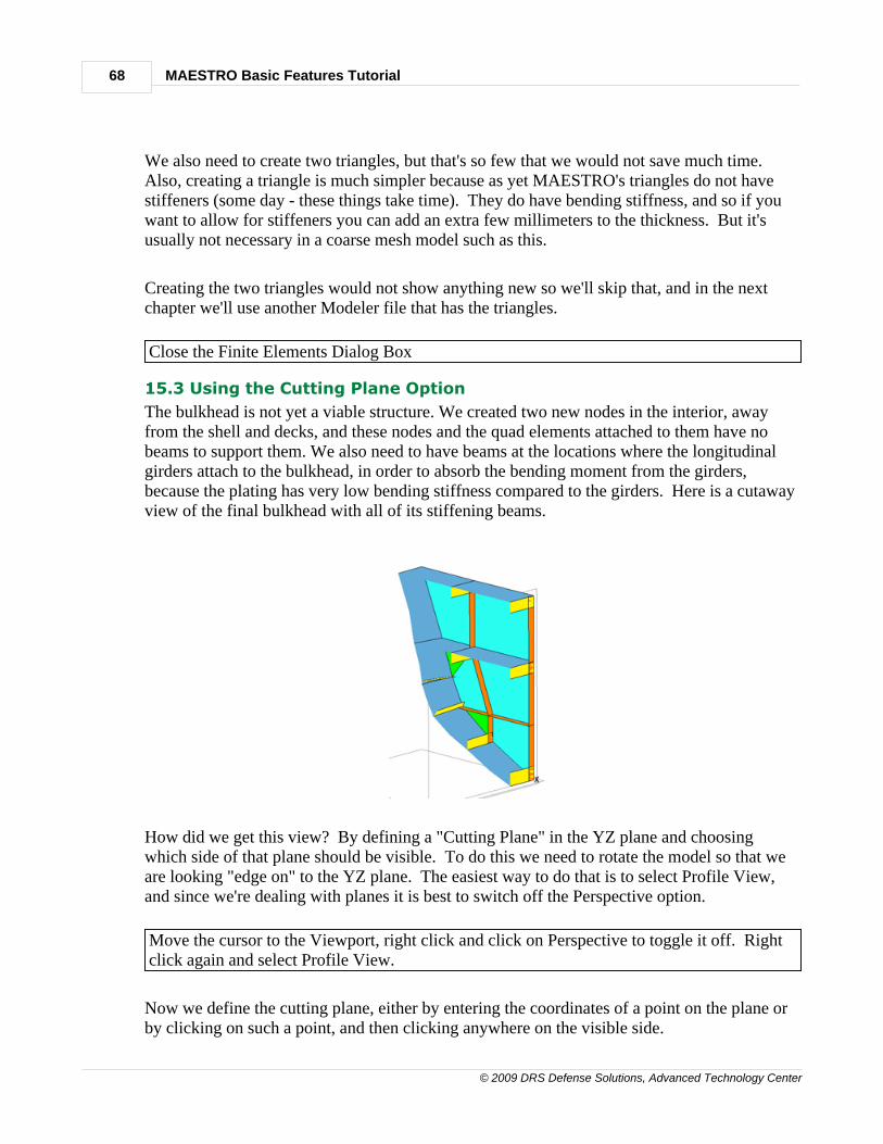
MAESTRO Basic Features Tutorial68
© 2009 DRS Defense Solutions, Advanced Technology Center
We also need to create two triangles, but that's so few that we would not save much time. Also, creating a triangle is much simpler because as yet MAESTRO's triangles do not havestiffeners (some day - these things take time). They do have bending stiffness, and so if youwant to allow for stiffeners you can add an extra few millimeters to the thickness. But it'susually not necessary in a coarse mesh model such as this.
Creating the two triangles would not show anything new so we'll skip that, and in the nextchapter we'll use another Modeler file that has the triangles.
Close the Finite Elements Dialog Box
15.3 Using the Cutting Plane Option
The bulkhead is not yet a viable structure. We created two new nodes in the interior, awayfrom the shell and decks, and these nodes and the quad elements attached to them have nobeams to support them. We also need to have beams at the locations where the longitudinalgirders attach to the bulkhead, in order to absorb the bending moment from the girders,because the plating has very low bending stiffness compared to the girders. Here is a cutawayview of the final bulkhead with all of its stiffening beams.
How did we get this view? By defining a "Cutting Plane" in the YZ plane and choosingwhich side of that plane should be visible. To do this we need to rotate the model so that weare looking "edge on" to the YZ plane. The easiest way to do that is to select Profile View,and since we're dealing with planes it is best to switch off the Perspective option.
Move the cursor to the Viewport, right click and click on Perspective to toggle it off. Rightclick again and select Profile View.
Now we define the cutting plane, either by entering the coordinates of a point on the plane orby clicking on such a point, and then clicking anywhere on the visible side.
Basic Features Tutorial 69
© 2009 DRS Defense Solutions, Advanced Technology Center
Go to the Main Menu, click on View, move down to Cutting Planes and then move over andselect YZ Plane.
In the Command Prompt window at the lower left of the MAESTRO window (see also Workspace Layout if you want details) you will see the prompt "Select point on plane or enterplane constant". The piece of structure that we currently see is 5,000 mm in the X directionand so we want a plane that is at about X = 4000. You can either enter 4000,0,0 in thewindow or you can just click on any point that is about 4/5 of the model width from the left. The latter is easier.
Click on any point that is about 4/5 of the model width from the left. It need not be a node.
Now the Command Prompt window says "Select/enter point on the visible side of the cuttingplane".
Click on any point that is to the right of the previous point. Again it does not have to be anode.
You should now see a narrow slice of the model.
Rotate and move (pan) the model to the position shown in the above figure.
Unfortunately, the cutting plane cuts off the endpoint labels and we need them for the nextsection. So we'll delete the cutting plane
Click on View, move to Cutting Planes, move down and click on Delete. Restore aperspective view by right clicking in the Viewport and toggling Perspective. You'll also wantto right click and select Fit.
Another way of getting a better view of the bulkhead is by erasing unneeded element types.
Click the View Options button click on Strake Plates, Strake Frames and Strake Girders.Also click on Stiffeners and then on OK.
We didn't erase Quads because then we could not see the bulkhead plating, and so the uptaketrunk is blocking the view. Therefore we'll use a different strategy - we will view the otherside of the bulkhead and put the beams on that side. Then, after creating all of them, we willflip each of them around to the other side.
Rotate the model so that you are looking at the outside surface of the bulkhead, opposite fromthe uptake trunk. Rotate, pan and zoom the model so that you can see most of the endpoint

MAESTRO Basic Features Tutorial70
© 2009 DRS Defense Solutions, Advanced Technology Center
labels.
15.4 Quick Construction of Beam Elements
Now we will create the bulkhead's stiffening beams. Here is what the result will look like,just before we flip the beam webs to the other side.
We first make the prototype beam, and let's say that will be the lowest of the three verticalbeams on the ship's centerline. In the Viewport you can see that the nodes for this beam are inline with endpoints 1 and 12. Earlier in this chapter (end of Section 15.1.1) we noted that theProperty ID of the beam property that we want to use is 5.
Click the Beam Elements button , click the ID button to get the next available ID number(2), go to the Property ID window at the far right, click the down-arrow and select 5.
The bottom window, Web Orientation, allows you to define the web orientation in six ways. To see five of these
click the down-arrow in the Web Orientation window.
The last one specifies the angle of the web relative to the positive normal of an adjacentelement (strake panel, quad or triangle). For the beam that we are creating, the adjacentelement is quad 3. Here is the figure from Section 15.2
Basic Features Tutorial 71
© 2009 DRS Defense Solutions, Advanced Technology Center
Click the Associated Element tickbox, click the down-arrow in Element Type and selectQuad, and in the Element ID window select 3.
The quad's node numbering is clockwise and therefore, by a right hand rule, the positivenormal points in the -X direction (into the page in the above figure). In the final configurationthis is the correct direction of the beam web, and so the angle of the beam web relative to thepositive normal is 0 degrees.
Go back to the Web Orientation window, click the down-arrow, select the last line and entera zero.
The six ways to define web orientation are explained in the beam section of CreatingAdditional Elements. The relevant paragraphs are Associated Element and WebOrientation. This is a complicated topic, and you should allocate some time to study it.
Finally we are ready to define the beam's two nodes and create it.
Click in the Node 1 window to activate the cursor for selecting nodes in the model. Movethe cursor to the node in line with endpoint 1 (bottom corner of the bulkhead) and click on it.The Node 1 window should now contain 1,2. Then move up to the node in line withendpoint 12 and click. The Node 2 window should now contain 12,2. Finally, click onCreate.
This first beam is visible only because it is in the ship's centerplane, but most of the beamsthat we are going to create will be hidden by the bulkhead. So here is where we will adopt thestrategy of creating the beams on the visible side and then flipping the beam webs over to thecorrect side.
In the Web Orientation window, change the zero to 180 and click Modify. Now that we have a prototype beam we can create the other beams very quickly, by clickingonly on nodes.To begin the Quick Creation process Normally we would click on Modify to be sure that the prototype properties are in the buffer,
but we have just done that. Go to the running man button click the down-arrow andselect Beam.
Now begins the node-clicking cycle. To create each beam you simply click once on the nodein the model that is to become beam node 1, and then double click on the node that is tobecome beam node 2. Begin with the beam that is to be directly above the prototype.
Click the node that is in line with endpoint 12, and then move up and double click the node

MAESTRO Basic Features Tutorial72
© 2009 DRS Defense Solutions, Advanced Technology Center
in line with endpoint 10.
Now create the third beam, whose nodes are in line with endpoints 10 and 8. Then do onemore (your choice) because from now on they are visible only because they are on the wrongside.
There are still four more beams to create, but you can stop here because they will all be therein the next file that we open - EX1G.MDL.
Since we are finished, it is very important to do two things. First
click the running man button again to toggle it off.
Secondly, since we are going to manipulate the newly created beams, we must update their IDnumbers.
Close the Finite Elements Dialog Box and then reopen it.
Now we'll demonstrate flipping the beam webs to the correct side.
In the Beam Dialog Box click in the ID window and then click on one of the beams. In theWeb Orientation window change 180 to 0 and click Modify.
No need to do the other beams because they will be correct in the next file. Whether you arestopping here or continuing to the next Session, is very important that when you are askedabout saving the changes you made to EX1F, you say NO.
1.16 16.0 Running a MAESTRO Job
16.0 RUNNING A MAESTRO JOB - ENTRY POINT 8
At this point, whether you are continuing from Chapter 15 or re-entering, you need a newMAESTRO file that has the new bulkhead and both the hogging and sagging load cases (andnot the stillwater loadcase).
Click on the Open File icon and double click EX1G.MDL. If you are continuing from theprevious chapter, answer NO about saving the previous file, EX1F.
Please see the Analyzing the Model section of the Manual for step-by-step instructions onsolving the model.
Basic Features Tutorial 73
© 2009 DRS Defense Solutions, Advanced Technology Center
1.17 17.0 Viewing Results
17.0 VIEWING RESULTS
For now we are finished with the Output Window and we want to make the Main ViewingArea as large as possible.
Here is where we use the small Load Case window near the right end of the upper Toolbar(but now on the left because it has "wrapped around" to a second line) to select and changethe load case. Let's start with the hogging load case.
Click the down-arrow and select STATIC LOADS + HOGGING WAVE.
17.1 Deformation and Stresses
Let’s first look at the deformation due to the hogging wave and the other loads.
In the Main Menu click on Results, and then on Deformed Model.
The effects of the hogging bending moment and the deck pressures are obvious. Let’s look atstresses – say longitudinal stress.
Click on Results, then on Stress, and then on Mid X Normal.
Since we are "squeezing" the Modeler into a half screen, the labels on the stress color bar arepartly cut off. To get more space for the main display window, we can hide two items that weare not currently using.
Hide the Parts Tree by clicking the X at its upper right. Hide the Refine Mesh toolbar bygoing to the Main Menu, clicking Tools and Toolbars, and then clicking on Refine Elementsto toggle it off.
Note that there is a special button to show or hide the Parts Tree , to the right of the ViewOptions button.
Toggle the button twice, to see how it works.
The parts tree can also be toggled on and off by selecting View > Set Window > Tree.
You may have to do even more to see the complete stress labels. If need be, you can shrink
MAESTRO Basic Features Tutorial74
© 2009 DRS Defense Solutions, Advanced Technology Center
this Tutorial window (drag the left boundary to the right) and expand the Modeler windowtemporarily.
The dark blue color indicates that the bottom panels have a compressive stress of about -227MPa, but we don’t know yet if there are any structural failures.
Restore the windows to a more equal size, but be sure that the Query button near theright end of the upper toolbar is visible.
17.2 Structural Adequacy
For all members and for all relevant failure modes and for all load cases, MAESTROcompares the actual stresses with the failure stresses, and for every one of these combinationsit generates an “adequacy parameter”, which is a number between –1 and +1. A negativevalue means that for that failure mode and load case, the member has failed, or at least thatthe safety margin is less than was specified (in the Job Info Dialog Box). Zero means that themember has exactly the required safety margin and no more. A positive value means that thesafety margin is larger than the specified value.
To see the results of the failure mode evaluation, you may need to re-run the model by
clicking the analyze button and then selecting MAESTRO under the Failure ModeEvaluation section at the bottom of the Analysis/Evaluation dialog.
Click on Results, move to Adequacy and dwell there.
You see the list of failure modes and their acronyms.
Move the cursor to the bottom, click on Minimum Value (All).
Looking at the color bar we see that the worst (most negative) adequacy parameter is –0.07and that red is used for the range from –0.01 to -0.07. The stiffened panels in the bottom arered and so they are slightly inadequate.
17.3 The Dynamic Query Feature
The Query button can be used to show all the details of any type of result: deformations,stresses and adequacies.
Move the cursor to the Query button (near the right end of the upper toolbar). Clickthe down arrow and click on Adequacy. Then move the cursor to the nearest of the fourbottom panels.
You see that the most negative adequacy parameter is the PCSF failure mode, which standsfor Panel Collapse, Stiffener Flexure. The underlying theory for this particular failure mode is
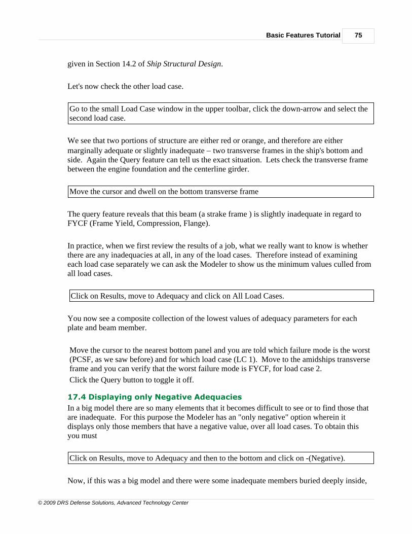
Basic Features Tutorial 75
© 2009 DRS Defense Solutions, Advanced Technology Center
given in Section 14.2 of Ship Structural Design.
Let's now check the other load case.
Go to the small Load Case window in the upper toolbar, click the down-arrow and select thesecond load case.
We see that two portions of structure are either red or orange, and therefore are eithermarginally adequate or slightly inadequate - two transverse frames in the ship's bottom andside. Again the Query feature can tell us the exact situation. Lets check the transverse framebetween the engine foundation and the centerline girder.
Move the cursor and dwell on the bottom transverse frame
The query feature reveals that this beam (a strake frame ) is slightly inadequate in regard toFYCF (Frame Yield, Compression, Flange).
In practice, when we first review the results of a job, what we really want to know is whetherthere are any inadequacies at all, in any of the load cases. Therefore instead of examiningeach load case separately we can ask the Modeler to show us the minimum values culled fromall load cases.
Click on Results, move to Adequacy and click on All Load Cases.
You now see a composite collection of the lowest values of adequacy parameters for eachplate and beam member.
Move the cursor to the nearest bottom panel and you are told which failure mode is the worst(PCSF, as we saw before) and for which load case (LC 1). Move to the amidships transverseframe and you can verify that the worst failure mode is FYCF, for load case 2.
Click the Query button to toggle it off.
17.4 Displaying only Negative Adequacies
In a big model there are so many elements that it becomes difficult to see or to find those thatare inadequate. For this purpose the Modeler has an "only negative" option wherein itdisplays only those members that have a negative value, over all load cases. To obtain thisyou must
Click on Results, move to Adequacy and then to the bottom and click on -(Negative).
Now, if this was a big model and there were some inadequate members buried deeply inside,

MAESTRO Basic Features Tutorial76
© 2009 DRS Defense Solutions, Advanced Technology Center
they would nevertheless be visible because all of the adequate members are transparent. Also,since the color bar now has only negative values, each color represents a much more preciserange of inadequacy.