
Madeleine Everton, Mariam Abdulameer, Felita Ong, Eric ...
93
UBC Social Ecological Economic Development Studies (SEEDS) Sustainability Program Student Research Report UBC Stormwater Detention: Detention Facility for Centre for Comparative Medicine (CCM) Madeleine Everton, Mariam Abdulameer, Felita Ong, Eric Vaags, Nadia Langenberg, Christina Di Iorio University of British Columbia CIVL 446 Themes: Water, Climate, Land April 8, 2019 Disclaimer: “UBC SEEDS Sustainability Program provides students with the opportunity to share the findings of their studies, as well as their opinions, conclusions and recommendations with the UBC community. The reader should bear in mind that this is a student research project/report and is not an official document of UBC. Furthermore, readers should bear in mind that these reports may not reflect the current status of activities at UBC. We urge you to contact the research persons mentioned in a report or the SEEDS Sustainability Program representative about the current status of the subject matter of a project/report”.
Transcript of Madeleine Everton, Mariam Abdulameer, Felita Ong, Eric ...

UBC Social Ecological Economic Development Studies (SEEDS) Sustainability Program
Student Research Report
UBC Stormwater Detention: Detention Facility for Centre for Comparative Medicine (CCM)
Madeleine Everton, Mariam Abdulameer, Felita Ong, Eric Vaags, Nadia Langenberg, Christina Di Iorio
University of British Columbia
CIVL 446
Themes: Water, Climate, Land
April 8, 2019
Disclaimer: “UBC SEEDS Sustainability Program provides students with the opportunity to share the
findings of their studies, as well as their opinions, conclusions and recommendations with the UBC
community. The reader should bear in mind that this is a student research project/report and is not an
official document of UBC. Furthermore, readers should bear in mind that these reports may not reflect
the current status of activities at UBC. We urge you to contact the research persons mentioned in a
report or the SEEDS Sustainability Program representative about the current status of the subject matter
of a project/report”.

Executive Summary
This report provides an overview of the project background, the conceptual designs
considered, justification of the preferred option and an in depth outline of the final detailed
design. In response to the current high risk of flooding to the University of British Columbia
(UBC) campus and surrounding residential and First Nations areas, the UBC Social Ecological
Economic Development Studies (SEEDS) Sustainability Program has retained Team 10 for the
design of a non-traditional, multi-use stormwater management system. A public outdoor
learning space was chosen for its overall functionality and minimal maintenance and
environmental impact to be the preferred design out of three conceptual designs.
Included in this document is the technical analysis, including geotechnical, structural and
hydrotechnical components, the framework for an environmental assessment and Indigenous
engagement, a project management plan, and a review of stakeholder engagement.
A geotechnical review of the site slope stability was completed with attention to the instability
of the Point Grey Cliffs in order to determine safe limits for site excavation. This was also taken
into account for the design of the structure’s four footings. SAP2000 was used for structural
analysis of the outdoor learning space’s roof.
A hydrological site analysis was conducted using past site evaluations as well as EPA SWMM
to obtain a solid understanding of the current conditions and stormwater drainage system. EPA
SWMM was used to determine the required water holding capacity in the case of 10 and 100
year storms. An outlet controlled orifice discharge concept was designed to meet the specified
maximum discharge rate.
Moving forward, a project management plan has been outlined in this report, consisting of
construction phasing, and scheduling, a cost estimate and methodology as well as methods of
stakeholder engagement.
2

Team Member Contributions to Final Detailed Design
Mariam Abdulameer ● Construction plan, specifications & detailed cost estimate
Christina Di Iorio ● Geotechnical design, structural design
Madeleine Everton ● Hydrotechnical analysis, geotechnical analysis
Nadia Langenberg ● Hydrotechnical analysis, drainage design
Felita Ong ● Maintenance plan, design life, technical drawings
Eric Vaags ● Structural design, detailed cost estimate
3

Table of Contents
1.0 Project Overview 6 1.1 Site Overview 7 1.2 Key Issues and Design Criteria 8
2.0 Overview of Final Design 10 2.1 Key Design Components 10
2.1.1 Foundations 10 2.1.2 Amphitheatre 10 2.1.3 Roof Structure 11
2.2 Design Criteria 11 2.2.1 Design Life 12 2.2.2 Design Loadings 13
3.0 Design Considerations 14 3.1 Environmental Considerations 14 3.2 Social Considerations 14 3.3 Economic Considerations 15
4.0 Technical Design 16 4.1 Structural Design 16
4.1.1 Roof Structure 16 4.1.2 SAP2000 Analysis 17 4.1.3 Outdoor Learning Space 18
4.2 Geotechnical Design 19 4.2.1 Geotechnical Model 20 4.2.2 Design of Footings 21 4.2.3 Retaining Structures 23 4.2.4 Slope Stability 25
4.3 Hydrotechnical Design 28 4.3.1 Hydrological Conditions 28 4.3.2 Current Stormwater Drainage System 30 4.3.3 EPA SWMM Analysis 31 4.3.4 Drainage Design and Considerations 36
5.0 Design Service Life 39 5.1 Maintenance Plan 39 5.2 Cost Estimate 39
6.0 Project Management Plan 41
4

6.1 Construction Planning 41 6.1.1 Construction Requirements and Specifications 41 6.1.2 Phasing of Construction Activities 42 6.1.3 Anticipated Construction Issues 42 6.1.4 Construction Schedule 43
6.2 Economic Analysis 44 6.2.1 Cost Estimate 44
6.3 Stakeholder Engagement 44
7.0 References 45
Appendix A: Structural Analysis 47 Appendix B: Technical Drawings 51 Appendix C: Construction Schedule & Cost Analysis 55 Appendix D: Stakeholder Engagement Plan 59 Appendix E: Hydrotechnical Design Calculations 61 Appendix F: Construction Specifications 62 Appendix G: Drawing Package 82
List of Figures
Figure 1: Project Location 8
Figure 2: Schematic of Soil Stratigraphy 21
Figure 3: Typical Footing Layout 22
Figure 4: Schematic of Typical Retaining Wall 18
Figure 5: Slope stability model in Geostudio SLOPE/W software 26
Figure 6: Materials used in the SLOPE/W model and their corresponding colours 27
Figure 7: Seasonal Fluctuations of Vancouver Precipitation from [6] 29
Figure 8: Vancouver Snow Cover from [7] 29
Figure 9: Map of Area Analyzed in SWMM (including a close-up view and an overview) 32
Figure 10: Plot of 1:10 Year Total Inflow into Node USL-50 34
Figure 11: Plot of the 1:100 Year Inflow 36
List of Tables
Table 1: Applicable Government Regulations 12
5

Table 2: Structural Loads 17
Table 3: NBCC 2015 Load Combinations 17
Table 4: Design Loads for Connections 18
Table 5: Summary of Concrete Design 19
Table 6: Summary of Footing Design 23
Table 7: Retaining wall characteristics 25
Table 8: 1 in 10 Year Stormwater Modelling, Inflow into Node USL-50 32
Table 9: 1 in 100 Year Stormwater Modelling, Inflow into Node USL-50 35
Table 10: Annual maintenance cost estimate 40
Table 11: Table of contents of construction specifications 41
Table 12: Project milestones 43
1.0 Project Overview
The University of British Columbia (UBC) South Campus is at risk of significant flooding in the
event of an extreme event such as a 100-year storm. The need for a new stormwater detention
facility has been identified in UBC’s Integrated Stormwater Management Plan (ISMP). This
facility will reduce the risk of flooding in the South Campus area.
Most of the current stormwater detention facilities on campus are conventionally built and UBC
is exploring non-traditional options to these facilities. As such, the UBC Social Ecological
Economic Development Studies (SEEDS) Sustainability Program intends to build a multi-use
stormwater detention facility, specifically one that integrates the built and natural environments
and incorporates a green infrastructure approach, on UBC’s South Campus. The key criteria of
being a multi-use facility means that it will serve as both stormwater management
infrastructure as well as an urban design feature for the community.
To design this multi-use facility, Team 10 has reviewed existing data and consulted various
stakeholders who may be impacted by this project. The facility was designed to meet
6

stormwater quality and quantity requirements and minimize adverse impacts to the
surrounding environment. Other considerations such as cost, the feasibility of construction,
and usefulness for the community were also taken into account in the design.
1.1 Site Overview
UBC’s South Campus is home to many research facilities such as TRIUMF, UBC Farm and the
Centre for Comparative Medicine (CCM) animal research facility. South Campus is also home
to Wesbrook Village neighbourhood, where over 12,500 students, staff, and alumni live. The
Point Grey cliffs, which are prone to erosion, are also in close proximity to the South Campus.
In addition, the Pacific Spirit Regional Park borders the South Campus. Areas within the South
Campus that are at risk of flooding include the intersection of Wesbrook Mall and SW Marine
Drive, the east side of TRIUMF, Acadia Park, and the intersection of Wesbrook Mall and West
16th Avenue.
The proposed stormwater detention facility is to be built in the area southwest of UBC CCM.
The site is located at the intersection of SW Marine Drive and Wesbrook Mall, as shown in
Figure 1. Presently, the site is a forested area with dense vegetation and is inaccessible by
foot.
7

Figure 1: Project Location
1.2 Key Issues
Three key issues of the site’s current condition have been identified:
1. Overland flooding during a 10-year and 100-year storm event: the size of the existing
stormwater sewer system is insufficient to hold the large quantity of water encountered
during an extreme event. In addition, rapid urbanization of the campus has led to
increased impervious area and thus surface runoff.
8

2. Erosion of cliffs surrounding Point Grey: erosion may be caused by flooding during a
heavy storm event and infiltration of the upper aquifer, which moves fine sediments off
the cliff face.
3. Stormwater quality: surface runoff often contains toxic contaminants and water quality
entering the stormwater system is sometimes not appropriate for discharge, causing
adverse effects to surrounding ecosystems, including riparian habitat.
9

2.0 Overview of Final Design
In the preliminary design stage, an outdoor learning space was chosen to be developed into a
final design out of three conceptual design options. The outdoor learning space serves as a dry
pond, allowing the space to be used for outdoor lectures, presentations, concerts, and other
events during the dry season. During the wet season, the space will detain stormwater. This
section describes design components of the outdoor learning space as well as the design
criteria used and the expected design life.
2.1 Key Design Components
2.1.1 Foundations
Concrete foundations were needed for each column that supports the amphitheatre roof and
so shallow footings were designed. Since the roof consists of both interior (higher load) and
exterior (lower load) columns, two different types of shallow footings were designed; 3.0 m
width and 5.0 m depth for the interior footings and 2 m width and 3.3 m depth for the exterior
footings.
In addition to the footings for each column, small retaining walls were designed for each
concrete step in the amphitheatre. These were designed to ensure safety to the facility users
by ensuring none of the steps would topple under lateral earth pressures. A schematic of a
typical retaining wall is shown in Figure 4. It was determined that a height of 1.5 m would be
sufficient to prevent toppling. The design of foundations is described in more detail in section
4.2 of this report.
2.1.2 Amphitheatre
Stormwater will be detained in an outdoor amphitheatre in the case of a storm event. The
amphitheatre has multiple steps to hold various stormwater levels. In the case of a 1:100 year
10

storm event, the amphitheatre’s maximum water storage capacity will be reached. However, in
a smaller, more frequent storm event, the amphitheatre can still serve its purpose of being an
outdoor learning space, albeit at a smaller capacity. The concrete steps of the amphitheatre
double as seating for users of the outdoor learning space. A stage has also been designed and
is located at the centre of the amphitheatre on the lowest elevation. Detailed drawings of the
amphitheatre can be found in Appendix G.
2.1.3 Roof Structure
To allow year-round usage of the facility, a roof structure covering the entire amphitheatre has
been designed. The design incorporates a green roof system that reduces runoff and
minimizes the impact of the facility on surrounding environment. The roof structure is described
in further detail in Section 4.1.1.
2.2 Design Criteria
Several design constraints and requirements have also been identified, including:
1. Regulatory: the proposed design shall adhere to applicable design codes and
government regulations (Table 1). The facility shall also be designed in accordance to
UBC policies, such as the UBC Land Use Plan. The UBC ISMP will also be referred to
throughout the process.
2. Environmental: a sediment control program needs to be included in the design to
ensure water quality is appropriate for discharge and will not disrupt surrounding
ecosystems.
3. Technical: the proposed detention facility needs to hold 2500 to 3000 m3 of stormwater
while limiting the release rate to 1.2 m3/s. The water holding facility needs to be
impermeable so as to limit infiltration to the upper aquifer, which would increase risk of
slope stability issues of the Point Grey Cliffs.
11

4. Cost: design of the facility shall also consider the budget allocated to it by UBC SEEDS.
The design may generate revenue through alternative uses, where opportunities exist.
5. Stakeholders: as the project is located on Musqueam land, cultural considerations
must be incorporated in the design to respect the Musqueam people and their input
must be included. Other societal considerations will also be incorporated through a
stakeholder engagement process.
Table 1: Applicable Government Regulations
Level of Regulation Applicable Regulations
Federal Government ● Fisheries Act ● Canadian Environmental Protection
Act
Provincial Government ● Environmental Management Act ● Water Act
2.2.1 Design Life
The outdoor learning space is expected to have an overall design life of 50 years. The typical
design life of underground stormwater detention tanks is 25-50 years [13]. Since the
amphitheatre is located outdoors, it is more accessible for maintenance purposes compared to
a traditional underground detention tank. The exposed areas of the facility will also mostly be
constructed using durable concrete. Therefore, the assumed design life of the amphitheatre is
50 years, which is on the longer end of the range. In addition, green roofs typically have a
design life of 30-50 years [14]. The steel roof structure designed is relatively simple compared
to typical building roof structures because it is a standalone structure. Design and construction
of the green roof is to be subcontracted to those with expertise in the area. As such, the design
and materials of the green roof are assumed to be durable and the roof is expected to have a
design life of 50 years as well.
12

2.2.2 Design Loadings
One of the main requirements of the facility is the ability to detain stormwater in the case of
1:10 and 1:100 year storm events. The hydrotechnical analysis performed resulted in volume
capacity requirements of 1753 m3 and 2803 m3 in the case of 1:10 and 1:100 year storms,
respectively. The amphitheatre has therefore been designed to meet this capacity requirement.
Details regarding the hydrotechnical analysis and modelling performed can be found in Section
4.3.3. For the roof structure, structural loads were determined using the National Building Code
of Canada (NBCC) load cases and combinations and are detailed in Section 4.1.2.
13

3.0 Design Considerations
3.1 Environmental Considerations
Design of the outdoor learning space focuses on synthesizing environmental and functional
aspects. The permeable aspects of the structure (the green roof, the false bottom and the step
spacing) will reduce surface runoff in the area and mitigate the effects of removing a portion of
the forested area. Native plant species will be used for the green roof, eliminating the
possibility of invasive plant growth and contributing to the natural aesthetic of the area. The
materials chosen for the design are locally sourced when possible. The use of concrete instead
of treated wood eliminates the environmental impact of possible chemical use and reduces the
maintenance requirements of the structure. Construction of the design will be planned and
carried out in a way that minimizes any noise pollution which may affect the area and
surrounding communities.
To ensure that the design upholds environmental sustainability principles and negative impacts
are sufficiently mitigated, proactive and extensive First Nations consultations will be
undertaken. The conception of the design was done with the neighboring First Nations
communities in mind.
3.2 Social Considerations
The outdoor learning space design will serve as a hub for the Wesbrook Village community and
the UBC community. This space will enable communities to come together by providing a
venue for celebrations and gatherings, therefore enhancing community engagement and
stimulated a greater connection to the natural environment. This space will also change the
social scenery in the area and encourage more social development within the facilities that
14

exist on South Campus. Employees of nearby facilities can also utilize this space for team
building and opportunities to enjoy the outdoors during work breaks.
As for the Indigenous community nearby, this space will allow for traditional practices and
ceremonies to be held close to the communities and offer a space to host other Indigenous
groups when visiting the area. The space also aligns with First Nations values which were
extensively consulted during the design conception and development.
3.3 Economic Considerations
The addition of the outdoor learning space to South Campus will provide an opportunity for
economic revenue to be collected by the Owner. The availability of the space for rental by
external parties for a variety of events will generate revenue throughout the year and especially
during warmer seasons. The events that are hosted at the space will also encourage economic
development in the area and allow for more exposure to the restaurants and businesses in the
South Campus. The design of the outdoor learning space emphasized materials and products
found locally in order to enhance the local economy and encourage economic development of
the UBC community.
15

4.0 Technical Design
4.1 Structural Design
The structural design for this project focused on the roof structure as well as the steps of the
outdoor learning space. These components were designed for the serviceability limit state
under the design load conditions as outlined in the following sections. These sections describe
the structural design considerations and the results of the analysis conducted with SAP2000, a
software used for design and analysis of structural systems.
4.1.1 Roof Structure
The purpose of the roof structure is to provide protection to the users of the outdoor learning
space from natural elements. Additionally, the design will include a green roof to reduce runoff
and mitigate some of the ecological impacts of the project. As discussed in the preliminary
design report, the roof design presented in this report was chosen as it is less complicated and
less costly than some of the other options considered, making it more appropriate for the
relatively small size of the project. Additionally, the chosen roof design covers the entire
outdoor learning space area which is beneficial to the year-round practicality of the design. The
design covers all of the outdoor learning space with 3 m of clearance between the bottom of
the roof and the ground level. The structure consists of eight trusses connected by I-beams
along the span length. Concrete columns along the edges of the learning space area support
the roof and transfer the weight to the foundations as described later in this report. The shell of
the roof will be a concrete slab overlaid with the green roof. Detailed drawings of the roof
structure can be found in Appendix G. The following section describes the load cases used to
analyze the structure and the results of the analysis.
16

4.1.2 SAP2000 Analysis
SAP2000 was used to analyze the roof structure based on the National Building Code of
Canada (NBCC) load cases [1]. A summary of the loads is included in Table 2 below.
Table 2: Structural Loads
Load Case and Variable Load (kN/m2)
Dead Load, D 132.8
Live Load, L 1 (for construction)
Snow Load, S 1.82
Wind Load, W 0.41
Earthquake Load, E Not Considered
Table 3 below summarizes the NBCC 2015 load combinations which were computed and used
to determine the governing load case that should be used in design.
Table 3: NBCC 2015 Load Combinations
NBCC Loading Combo
Principal Loads Companion Loads
Total Loading (kN/m2)
1 1.4D - 185.92
2 1.25D + 1.5 L 0.5S 168.41
3 1.25D + 1.5L 0.4W 169.23
4 1.25D + 1.4L 0.4S 167.30
As shown in Table 3, Loading Combo 1 is the governing case as it yields the highest loading
values and so Loading Combo 1 was used as the design load. Using this load case, the roof
structure was subjected to a static linear analysis and determined to be structurally stable. It
17

should be noted that earthquake loading was not considered as part of the design as it is
beyond the expertise of the consultant team for this design. It is recommended that an
engineer with structural dynamics expertise be consulted to determine if the roof design
requires modification.
Steel frame sections were analyzed using Canadian Institute of Steel Construction (CISC)
analysis to determine the percentage of their capacity in use during loading. Likewise, the
concrete sections were analyzed using the Canadian Standards Association (CSA) concrete
analysis. Based on the results of these analyses, the roof structure was determined to be
feasible for the material types and sizes included in this design. Diagrams of the forces and
moments in the roof members under loading are included in Appendix A.
Using the results of the SAP2000 static linear analysis, the maximum forces and moments in
the steel members were determined and used to design the connections between roof
members. The design loads for connections are summarized in Table 4 below.
Table 4: Design Loads for Connections
Maximum Shear Force (kN) Maximum Axial Force (kN) Maximum Moment (kNm)
1.19 2.42 1.51
Based on these design loads, connections were designed as shown in the detailed drawings in
Appendix G.
4.1.3 Outdoor Learning Space
The structural considerations for the outdoor learning space focused on the steps, platforms
and column footings. As these elements of the design will be cast directly against the earth, it
is expected that shear forces, tensile forces and moments will be minimal provided the ground
18
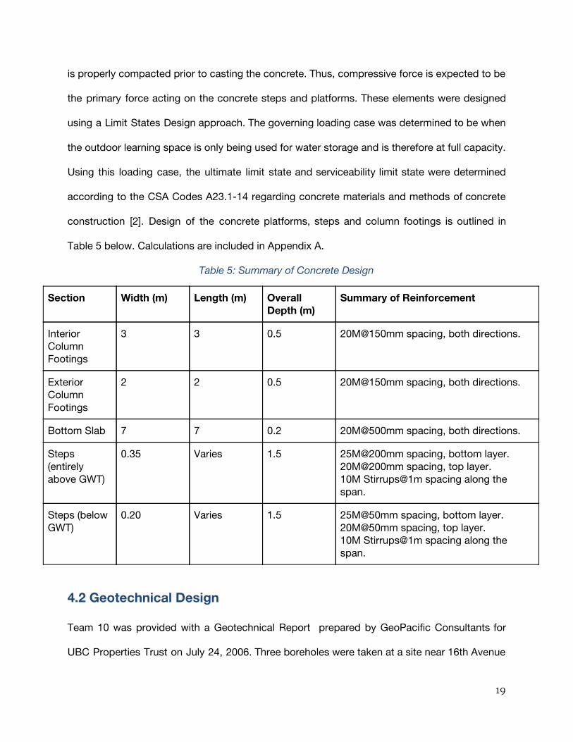
is properly compacted prior to casting the concrete. Thus, compressive force is expected to be
the primary force acting on the concrete steps and platforms. These elements were designed
using a Limit States Design approach. The governing loading case was determined to be when
the outdoor learning space is only being used for water storage and is therefore at full capacity.
Using this loading case, the ultimate limit state and serviceability limit state were determined
according to the CSA Codes A23.1-14 regarding concrete materials and methods of concrete
construction [2]. Design of the concrete platforms, steps and column footings is outlined in
Table 5 below. Calculations are included in Appendix A.
Table 5: Summary of Concrete Design
Section Width (m) Length (m) Overall Depth (m)
Summary of Reinforcement
Interior Column Footings
3 3 0.5 20M@150mm spacing, both directions.
Exterior Column Footings
2 2 0.5 20M@150mm spacing, both directions.
Bottom Slab 7 7 0.2 20M@500mm spacing, both directions.
Steps (entirely above GWT)
0.35 Varies 1.5 25M@200mm spacing, bottom layer. 20M@200mm spacing, top layer. 10M Stirrups@1m spacing along the span.
Steps (below GWT)
0.20 Varies 1.5 25M@50mm spacing, bottom layer. 20M@50mm spacing, top layer. 10M Stirrups@1m spacing along the span.
4.2 Geotechnical Design
Team 10 was provided with a Geotechnical Report prepared by GeoPacific Consultants for
UBC Properties Trust on July 24, 2006. Three boreholes were taken at a site near 16th Avenue
19

and Westbrook Mall, less than 1 km from the location of the proposed stormwater detention
facility (“site”). Due to the limitations of the site, a site investigation was not able to be carried
out, therefore the soil stratigraphy shown in the three borehole results is assumed to be
representative of those at the site. Based on the available information, the most appropriate
values were used when determining properties of the subsurface conditions.
4.2.1 Geotechnical Model
The depth of the water table was taken to be at 3.96 m below the ground surface. This value
was chosen out of the available data as the closest identified depth to the ground surface. A
higher water table generally results in less ideal soil parameters; due to overall lower soil
stability and potential for more damage from liquefaction, due to its undrained conditions.
Once all relevant data was analyzed and interpreted, appropriate values for critical soil
parameters such as the bulk unit weight, were chosen based on both calculation and
approximation for each soil layer. The soil stratigraphy suggested by the borehole data in [3]
was the primary data source used to develop these values. A schematic rendering of the soil
stratigraphy and profile is shown on the following page (Figure 2).
Several assumptions were made in the development of this model for simplicity of analysis and
understanding of site conditions. The assumptions made are consistent with Terzaghi’s widely
used 1-Dimensional soil consolidation theory. Primarily, the soil layers are assumed to be
laterally homogeneous, so that the below model is assumed to hold true for the entirety of the
site. It was also assumed that all soil within a ‘layer’ is entirely homogeneous. The schematics
were used to determine footing and retaining wall failure, as these are the subsurface
conditions all structural and hydraulic considerations were subjected to.
20

Figure 2: Schematic of Soil Stratigraphy
4.2.2 Design of Footings
Concrete footings were designed for placement underneath each structural column, which
supports the roof of the amphitheatre and all associated structural loading. These footings
were designed as a shallow foundation (ie: foundation with a depth to width ratio of less than
2.5). The shallow footings designed are sufficient for the loading that will be imposed on the
underlying soil stratigraphy. The roof loading has been assumed to be evenly distributed over
20 axially loaded interior columns which support the roof. Each column would therefore
experience a compressive force of 9823 kN, which would be transferred to the footing as
downward point load P. Each column takes the force from the column tributary area, which, as
21

aforementioned, includes wind loading, snow loading, and self-weight of the roof structure. A
schematic of the loading each square foundation (with dimensions B x B, and depth below
ground surface of Df) would experience is shown below in Figure 3. A suitable footing width for
the square footing is 3.0 m, with the depth of footing (Df) set at 5.0 m below ground surface. P
in the below schematic represents the axial loading imposed on each foundation from the
above columns.
As the exterior columns are subjected to a lower load of 5242 kN, due to the smaller tributary
area, 2m square footings will be used, with a footing depth of 3.3m. This minimization the
potential for differential settlements, and will be discussed later in this section.
Figure 3: Typical Footing Layout
The footings have been designed against two main cases: bearing capacity failure, and
settlement. Bearing capacity failure entails the foundation overturning due to excessive
loading. The potential for bearing capacity failure has been minimized by use of appropriate
dimensions for each footing. The design factor of safety was set at 2.5. This means that the
footing dimensions were calculated with the design bearing capacity being 2.5 times lower
than the footing’s ultimate bearing capacity. Beyond the ultimate bearing capacity, overturning
22

of the foundation can be expected to occur, which could cause major negative structural
implications. Thus, the use of a high factor of safety accounts for the complex nature of soil
and unforeseen variability or weak spots in soil conditions. This is consistent with good
geotechnical engineering practice.
Minimizing differential settlement between footings, as well as minimizing local settlement of
each footing, has been considered. The exterior footings have been designed to smaller
dimensions to ensure they will settle by the same amount as the interior columns. Upon a
settlement analysis, it was determined that at the design sizes and depths, the expected
long-term settlement is in the range of 60 to 70mm. Differential settlement – different sections
settling by different amounts – may cause major problems to the structure, and can severely
compromise stability and structural integrity. The bounds that were placed on the settlements
are: no more than 70 mm of settlement per foundation, and a differential settlement of less
than 1/500 of the span length between the foundations. The foundation dimensions chosen,
which are summarized below must meet settlement requirements, and shall also resist failure in
bearing capacity.
Table 6: Summary of Footing Design
Column Type Number of Columns Width (B) Depth of Footing
Interior 16 3.0 m 5.0 m
Exterior 4 2.0 m 3.3 m
4.2.3 Retaining Structures
The amphitheatre requires excavation to a depth of 5.5 m below the ground surface in order to
accommodate seating in the dry season. However, the deepest excavation extends to 7.5 m
below the ground surface in the middle of the amphitheater, due to the false bottom that acts
23

as a stormwater detention pond during heavy rainfall events. Each concrete seat backing in the
design acts as a small retaining wall, as it retains the soil behind it. The gravity retaining
structures were analyzed to ensure the structure does not pose any safety risks to facility users
or to the structure itself. As such, each seating level of the amphitheatre will consist of a
retaining wall that will prevent the earth from spilling into the pit of the amphitheatre. A
schematic of a typical retaining wall is shown in Figure 4 (following page). Each wall has been
designed with a height of 1.5m, at which it is estimated that the active earth pressures (lateral
pressure from the soil acting to overturn the wall) are balanced by the passive earth pressures
(preventing the wall from overturning) and where the slope is expected to be stable. The wall
thickness varies, from 350 mm for retaining walls above the groundwater table, to 200mm for
retaining walls below the groundwater table, due to the lower unit weight of water when
compared to soil.
An analysis of the wall stability, for walls both above and below the groundwater table, was
carried out using Coulomb’s method of analysis. Values obtained were then compared to
values determined using WALLAP, to ensure the use of approximate values. In calculation, the
weight of the above lying concrete was considered as a surcharge, and the lateral forces acting
on active and passive sides of the wall were analyzed by simplifying them as a point load and
performing an equilibrium analysis using the properties of concrete. The Coulomb method was
used as it is a simple and physically representative method of determining retaining structure
stability.
24

Figure 4: Schematic of Typical Retaining Wall
Gravity walls were used in design, due to the shallow depth of the walls, and the low lateral
pressures acting on the walls. Analysis determined that gravity walls are a sufficient means of
achieving our design goals, and are simple to construct, facilitating future project logistics as
well. A summary of retaining walls is shown below in Table 7.
Table 7: Retaining wall characteristics
Wall Type Number Depth D (m below ground surface)
Wall Thickness t (mm)
Entirely Above GWT 6 1.5 m 350
Below GWT 5 1.5 m 200
4.2.4 Slope Stability
A solid majority of the subsurface conditions are sandy soils, and the structure is situated
almost entirely above the highest observed depth of water table. A typical method of slope
stability analysis that is widely used is the “wedge method” of analysis, in which all of the
driving forces that could cause the slope to fail are considered and summed. Then, the
frictional resistances of the soil are also considered as resisting forces. If the sum of the
25

resisting forces (friction) is greater than the weight of the soil wedge, slope stability is not of
concern. If the frictional resistance is not large enough to prevent a slide, soil nails or anchors
could be utilized to improve the stability of the excavation.
Geostudio SLOPE/W software (SLOPE/W) has the options of using the Morgenstern-Price
method of analysis, the Bishop method or Janbu method. The Morgenstern-Price method is
similar to the “Wedge” method in that equilibrium must be carried out on the wedge (or slip
surface area) to analyze the forces and moments acting on the wedge. The wedge is typically
broken up into many different “slices” to ensure a more accurate response.
The Bishop method is very similar to Morgenstern-Price but is more simplified and uses less
“slices” in the analysis. Janbu’s method is again quite similar however instead of looking at
moments acting on the slices, it looks at shear forces.
There is no “correct” method of analysis, simply many different ways of going about it.
A model was created in SLOPE/W with the amphitheatres dimensions and shape, as well as
the soil materials that are displayed in Figure 2 above. The model is shown below in Figure 5.
Figure 5: Slope stability model in Geostudio SLOPE/W software
26

Figure 6 below shows what material each colour in the model corresponds to.
Figure 6: Materials used in the SLOPE/W model and their corresponding colours
Despite the model being created, the analysis was not able to be carried out due to the
limitations of the Student Licence of this software. The student licence does not allow for more
than 3 materials to be inputted and there are many more in this project’s soil stratigraphy.
Therefore, the slope stability modelling is deemed to be outside the scope of this report.
However, due to the nature of the design, and the step/retaining structure solution, slope
stability is not anticipated to be a governing failure mechanism of any aspects of the
amphitheatre. The excavated slope of the design dimensions can be approximated by 1V:2H (1
unit vertical per 2 units horizontal), which is generally a stable slope, and it would be extremely
unlikely for it to fail without warning.
27

4.3 Hydrotechnical Design
4.3.1 Hydrological Conditions
The South Campus Catchment consists of a relatively even mix of developed and forested
area. An environmental assessment of the region was conducted in November 2004 which
found the approximate land use division to be 45% developed and 55% second growth forests
[4]. The results from [4] found no apparent natural surface waterways within the catchment,
however it was noted that a perched water table exists. In a previous study conducted by
Piteau Associates, the groundwater levels were determined to be at depths of at least 45
meters [3]. Groundwater behavior and the urban development are important factors in
determining the hydrological environment of the site. The results from [4] confirmed that the
catchment drainage routes have been affected by development of the UBC campus and
surrounding communities.
The Water Survey of Canada labels British Columbia’s hydrological setting as one of the most
variable and complex with variable precipitation and annual runoff potential as high as 3000
mm in coastal basins [5]. This is reflected in our review and assessment of the hydrological
patterns present in the South Campus region, historical Vancouver weather data as well as the
findings from [3]. Vancouver weather statistics were reviewed showing a wet season from
October to March and a dry season from April to September [6]. Peak annual precipitation from
this period occurred in either November, December or January with peaks ranging from 200 to
250 mm [6]. Figure 7 demonstrates this seasonality.
28

Figure 7: Seasonal Fluctuations of Vancouver Precipitation from [6]
Historical snow cover data was also reviewed. From November to March some snow cover
was observed with levels from 0 to 20 cm [7]. Snow cover was observed to be relatively
consistently confined to these months, however, outlying events have occured. Figure 8 below
shows snow cover in the Vancouver region over the past five years.
Figure 8: Vancouver Snow Cover from [7]
Limitations on this data should be noted. For more specific results, longer time periods would
be required, however, station data near the UBC campus is sparse. Furthermore, these values
fall well inline with other assessments, namely those conducted in [3] and [4]. The work in [4]
found the annual precipitation to be 1225.6 mm/year with the driest month being July and the
wettest November and prevailing winds incoming from the northwest and west. A 30 year
period from 1961 to 1990 was reviewed in [3], finding annual precipitation to be 1288.6
mm/year where December was observed to be the wettest month and July the driest. Slight
variations are present between each of these measurements, however, a consistent trend is
29

present. Furthermore, as outlined in section 3.4.3 EPA SWMM Analysis, the results from the
SWMM analysis conducted for the preliminary design are consistent with extreme events
based off of the average annual precipitation values found above.
Behavior of runoff and infiltration is a key aspect of this project. The stability of the Point Grey
Cliffs have been a central element of design considerations throughout both the conceptual
and preliminary design phases. The erosion and potential for further erosion of the Point Grey
Cliffs pose a risk to the site and decreased slope stability due to further development must be
mitigated [4]. The results of [3] determined that precipitation on the Point Grey Peninsula
partially infiltrates to the top of the lower permeability till layer of the ground. From there, water
may either move along the till laterally or infiltrates downward through the till layer [3].
Furthermore, [4] also established that transpiration losses to water runoff are great due to the
amount of second growth forest presence in the area. As accounted for in the preliminary
design presented in this report, infiltration to the upper aquifer due to the development of a
stormwater detention system must be prevented and monitored in order to reduce the
potential for increased slope stability of the Point Grey Cliffs. This is specifically due to the
potential for infiltrated groundwater flow to propagate north towards the cliff from its position
on the till [4].
4.3.2 Current Stormwater Drainage System
The current stormwater management system present in the South Campus site has
experienced various expansions accompanying the increasing development to the UBC
campus and surrounding areas. UBC’s ISMP outlines the current stormwater drainage present
in the area. The urban campus is drained by multiple storm sewers as well as open drainage
channels which flow to three stream outfalls and one spiral vertical drain owned by Metro
30

Vancouver [8]. The South campus catchment receives runoff and drainage from Acadia Park,
Hampton Place, as well as the south campus region [8]. The catchment discharges to the
Booming Ground Creek Watershed located to the south-east of the South Campus catchment
[8]. Discharge to the Booming Ground Creek Watershed is a result of the current storm
drainage system diversion of water and is the only flow present to the creek during the dry
season [4]. The presence of fish habitat is confirmed by [4], which is supported by the Booming
Ground Creek flow. The assessment conducted in [4] described additional drainage channeled
to the south east of the catchment and discharging from the cliffs. Additional runoff is
channeled by ditches parallel to South West Marine Drive and towards the Fraser River [4].
Despite improvements to the regions stormwater management system due to development of
the area, the infrastructure in place is outdated.
4.3.3 EPA SWMM Analysis
Analysis was undertaken on the software EPA SWMM for a 1 in 10 and 1 in 100 year storm
event simulation. The total inflow from node USL-50 (shown on Figure 9 in the red circle) was
found for each storm event to determine if the detention facility would be able to accommodate
for these volumes of stormwater. The map below in Figure 9 shows the area near the project
site, including the analyzed node and an overview map outlining the region which was
analyzed. The red square on this map indicates where the specific section is. The project site is
outlined with the blue box on the close-up map. The black squares represent sub-catchments,
with the dotted lines representing the direction of flow from the sub-catchments to the nearest
pipe. The black circles represent the nodes, which are where multiple pipes meet and flow can
be measured. The black lines are the pipes underground.
31

Figure 9: Map of Area Analyzed in SWMM (including a close-up view and an overview)
1 in 10 Year Stormwater Model Node USL-50 Total Inflow
Table 8: 1 in 10 Year Stormwater Modelling, Inflow into Node USL-50
Time of Day
Total Inflow into Node (L/s)
Total Inflow into Node (m3/s)
Time of Day
Total Inflow into Node (L/s)
Total Inflow into Node (m3/s)
1:00 15.82 0.016 12:00 312.55 0.313
2:00 56.45 0.056 13:00 300.71 0.301
3:00 77.42 0.077 14:00 295.65 0.296
4:00 80.27 0.080 15:00 287.67 0.288
5:00 87.33 0.087 16:00 277.74 0.278
6:00 103.33 0.103 17:00 266.26 0.266
7:00 123.17 0.123 18:00 256.93 0.257
8:00 162.1 0.162 19:00 249.07 0.249
8:30 652.72 0.653 20:00 241.08 0.241
8:45 688.14 0.688 21:00 293.53 0.294
32

9:00 688.89 0.689 22:00 244.19 0.244
9:15 566.62 0.567 23:00 214.39 0.214
10:00 330.67 0.331 0:00 198.68 0.199
11:00 320.77 0.321 - - -
The table above shows data taken from SWMM and represents the flow at node USL-50 (the
pipe junction downstream of the project site). SWMM software was used to model the
stormwater flow for a 1 in 10 year storm event. The model ran the storm event at every 15
minute increment for 24 hours, and the data for every hour plus the peak flows in red are
displayed in Table 8 above. The data in red represents the peak flows over the 24 hour period,
lasting a total of 45 minutes.
To determine if the volume of water from these peak flows is larger than the capacity of the
detention center (3000 m3), the following calculations were carried out:
verage of peak f lows 5 minutes pproximate peak stormwater volumeA * 4 = A
verage of peak f lows 0.65272 .68814 .68889 .56662)/4 0.649 m /sA = ( + 0 + 0 + 0 = 3
.649m /s 0s/1min 5mins 753 m0 3 * 6 * 4 = 1 3
The approximate maximum volume the detention facility would have to accomodate in the
event of a 1 in 10 year storm event is 1753 m3. Since the detention facility can hold a maximum
of 3000 m3, it can successfully handle a 1 in 10 year storm event. A plot of the node’s total
inflow in L/s is displayed in the figure below.
33

Figure 10: Plot of 1:10 Year Total Inflow into Node USL-50
34

1 in 100 Year Model Node USL-50 Total Inflow
Table 9: 1 in 100 Year Stormwater Modelling, Inflow into Node USL-50
Time of Day
Total Inflow into
Node (L/s)
Total Inflow into
Node (m3/s)
Time of Day
Total Inflow into
Node (L/s)
Total Inflow into
Node (m3/s)
1:00 17.16 0.017 12:00 550.98 0.551
2:00 79.44 0.079 13:00 507.55 0.508
3:00 100.16 0.100 14:00 471.77 0.472
4:00 102.18 0.102 15:00 446.65 0.447
5:00 112.54 0.113 16:00 425.99 0.426
6:00 134.27 0.134 17:00 407.28 0.407
7:00 164.51 0.165 18:00 393.38 0.393
8:00 277.31 0.277 19:00 377.64 0.378
9:00 1014.16 1.014 20:00 359.73 0.360
9:15 1038.01 1.038 21:00 441.14 0.441
9:30 1047.67 1.048 22:00 365.42 0.365
9:45 1052.62 1.053 23:00 316.08 0.316
10:00 913.45 0.913 0:00 291.18 0.291
11:00 604.36 0.604 - - -
The data in Table 9 above is taken from the SWMM model for a 1 in 100 year storm event. The
peak flows occur from 9:00 am to 9:45 am and are highlighted in red text in the table. Similarly
to the model for the 1 in 10 year storm event, data points were taken every 15 minutes for a 24
35

hour period and the data for every hour is displayed. To find the maximum volume the
detention facility would need to accommodate, the following calculations were carried out:
olume of stormwater (m ) verage of the peak f lows 0 seconds/min 5 minsV 3 = A * 6 * 4
verage of peak f lows (m /s) 1.014 .038 .047 .053)/4 .038 m /sA 3 = ( + 1 + 1 + 1 = 1 3
olume of stormwater (m ) .038m /s 0s/min 5mins 803 mV 3 = 1 3 * 6 * 4 = 2 3
From the calculations above, the maximum volume of stormwater that will need to be stored in
the detention facility is 2803 m3. It can be concluded that for a 1 in 100 year storm event, the
detention facility can hold the water without flooding. A plot of the node’s total inflow is
displayed below in Figure 11.
Figure 11: Plot of the 1:100 Year Inflow
4.3.4 Drainage Design and Considerations
Drainage design and considerations were undertaken and analyzed. Metro Vancouver’s
Municipal Water Use Guidelines were taken into account with respect to the hydrological
analysis completed and discussed in Section 4.3.1 and 4.3.2. Due to the nature of Metro
Vancouver’s many water systems, it was required that all discharges be treated as if they are
36

expected to come into contact, or in some way interact, with fish habitat [9]. Therefore,
filtration of the water draining from the detention facility has been implemented using the gravel
fill in the facilities false bottom. This fill will act to filter out particulates which may happen to
reach the facility. Due to the location of the amphitheatre, it is not expected that contaminated
runoff will travel through the surrounding forest to the amphitheatre itself, however, if it should
occur, the gravel bottom will act to trap and detain harmful particulates.
To ensure that the design facilitates the drainage of runoff during and after a storm, an orifice
discharge concept was used. Preliminary design findings initially suggested that a pump
drainage system could be implemented. Main components of the pump design included the
required pump capacity and pump operation in a varied weather dependent scenario. Due to
the inconsistent and relatively rare occurrence of extreme storm events and the designed static
runoff detention capacity, the required capacity of the pump was expected to be significantly
lowered. Intermediate runoff storage provided for much smaller pump requirements [10]. Due
to the nature of the false bottom design component, the preliminary pump design consisted of
a mixed flow submersible pump. Mixed flow pumps operate using a combination of physical lift
and centrifugal force driven by a power source [11]. Incorporating a submersible ability to the
design would also have reduced design complications, maintenance requirements and
therefore the overall capital cost required [11]. However, after pursuing this design option
further, it was determined that the project did not offer sufficient head consistently enough to
make a pump a feasible option.
Due to the relative size of the design, a pump system was deemed to be an unnecessary and
inefficient option. Therefore, drainage was accounted for in the design in three ways. First, the
37

green roof would detain and facilitate drainage. Second, the steps of the amphitheatre allow for
natural infiltration of stormwater back into the ground between the concrete structures. Third,
the orifice, located at the center of the false bottom, was designed to allow drainage flow
below allowed threshold. The use of a circular orifice allows for the control of discharge of
stormwater by the geometry of the outlet. A simple orifice discharge equation was used to
calculate the maximum size of the orifice. Calculations for the size of the orifice were
completed with reference to [12] and can be found in Appendix E, along with the relevant
assumptions and values used. The maximum discharge of 1.2 cubic meters per second was
used, along with a discharge coefficient of 0.62 as is standard for a circular orifice. The
maximum head was taken to be the 8 meters, corresponding to the structural design of the
detention facility. The final orifice was sized to have a maximum area of 0.1 square meters. To
facilitate drainage from the false bottom runoff detention and pump outflow, addition drainage
pipes will be added to the site. These pipes will function to connect the stormwater
management addition to existing and available drainage which is discussed in Section 3.4.2:
Current Stormwater Drainage System. The additional drainage pipe will be 30 m long in order
to connect the detention facility to the outfall drainage at South West Marine Drive. The pipe
will be a HDPE pipe.
38

5.0 Design Service Life
5.1 Maintenance Plan
To ensure that the facility can be serviceable throughout its design life, regular maintenance is
required. Maintenance of the facility can be divided into two: maintenance of the green roof
system and the amphitheatre itself. Maintenance of the green roof system can be quite
complex. Some municipalities, such as City of Toronto, requires a detailed maintenance plan in
order to obtain a green roof permit [15]. Since design of the green roof itself is intended to be
subcontracted to ZinCo, a green roof manufacturing company, maintenance of the green roof
shall be outlined in greater detail by ZinCo. However, maintenance of the green roof should at
least include the following: fertilization, weed control, debris removal, and drain inspection. For
the rest of the roof system, yearly structural inspections are required to monitor integrity of the
system. Moreover, inspections allow the early detection of structural problems, which can
therefore be promptly addressed. Maintenance of the amphitheatre entails cleaning of the
drainage pipe that is likely to be clogged with debris and sediment that would accumulate after
a period of heavy rainfall. The concrete steps should also be pressure washed once a year to
minimize stains from oil and dirt. In addition, yearly inspections are recommended to ensure
the facility is structurally safe and is able to properly hold and discharge water. Finally,
landscaping the surroundings of the facility should also be performed once every two months.
5.2 Maintenance Cost Estimate
The estimated annual maintenance cost is $17,920. The breakdown of this estimate is shown
in Table 10 below.
39

Table 10: Annual maintenance cost estimate
Item Frequency (per year) Unit Cost Annual Cost
Green Roof System
Sediment Removal 3 $500 $1500
Fertilization 3 $500 $1500
Weed Control 3 $500 $1500
Inspection 1 $1000 $1000
Roof System (Excluding Green Roof)
Inspection 1 $1000 $1000
Amphitheatre
Sediment Removal 3 $500 $1500
Pressure Washing 2 $500 $1000
Inspection 1 $1000 $1000
Landscaping 6 $1000 $6000
Subtotal $16,000
GST $800
PST $1120
Total Annual Maintenance $17,920
40

6.0 Project Management Plan
The following section will outline a proposed construction plan for the owner to consider as a
way to facilitate the construction of the outdoor learning space. This section also includes a
detailed construction schedule as well as any phasing and sequencing necessary. Section 4.2
will outline a detailed cost estimate of the capital project costs and a stakeholder engagement
plan to be reviewed by the Owner.
6.1 Construction Planning
6.1.1 Construction Requirements and Specifications
In order for construction to commence in a timely manner and with proper coordination, it is
recommended that the awarded contractor engages in a pre-construction meeting with the
Owner’s Representative or Project Manager (see Appendix F - Section 01 00 00 - General
Requirements for definitions), on-site, in order to review existing site conditions and to confirm
the proposed site plan. Team 10 has developed a set of construction specifications with
accordance to UBC policies and requirements as summarized in table 11 below. Team 10
recommends a thorough review of the attached specifications in Appendix F to be undertaken
by the Owner in order to ensure there are no contradictions or overlaps with the tender
documents issued by the Owner.
Table 11: Table of Contents of Construction Specifications
Section Number
Title Number of Pages
01 00 00 General Requirements 5
01 14 00 Work Restrictions 3
41

01 35 29 Health, Safety and Emergency Response Procedures 2
03 30 00 Cast-in-Place Concrete 3
03 61 00 Non-Shrink Structural Grout 2
07 33 63 Vegetated Protected Membrane Roofing 1
31 22 00 Grading 2
6.1.2 Phasing of Construction Activities
Physical space on South Campus is limited and often constraints construction taking place in
the area. Due to this constraint, haul trucks, concrete pumps and all other significant
machinery will need to be parked alongside SW Marine Drive until needed. The coordination of
heavy machinery arrival on-site will require exceptional communication between the site
superintendent and the machinery operators. The delay caused by phasing the arrival of
construction machinery is reflected in the detailed construction schedule in Appendix C. The
Owner may also want to consider phased construction if complete funding for the project may
not be secured instantly. Phasing may also be considered after the site has been graded and
can be rented for revenue which then supplements funding. Additionally, the construction can
be phased such that the outdoor learning space seating is constructed prior to the installation
of the roof, in order to generate revenue through the rental of the space. It is important to note
that Team 10 recommends securing complete funding and avoiding phasing in order to
minimize prolonged environmental and traffic disruption in the area.
6.1.3 Anticipated Construction Issues
As mentioned in Section 6.1.1, the anticipated construction issues are due to traffic
coordination on South Campus. A lack of coordination and sufficient communication by the
42

Project team may lead to project delays due to the physical constraints of the site. Team 10
also anticipates some risk in the delivery and the offloading of large steel sections and
columns. This can be mitigated through the coordination of sufficiently sized cranes and
delivery trucks which are within the physical space limits of the site. Due to procurement
methods, the vegetated roof design will be done by others, which poses a medium risk in the
delivery of the project. This risk can be mitigated by integrating the design lead for the
vegetated roof at the commencement of the project for maximum exposure to the project.
Team 10 anticipates that complications may arise when connecting the false bottom outlet
pipes back into existing utilities; this requires significant coordination with UBC Utilities and
failure for sufficient notice may delay the project.
6.1.4 Construction Schedule
Project milestones are outlined in Table 12 on the following page; a full preliminary schedule
can be found in Appendix C. The following construction schedule assumes a starting date of
May 2019 and an estimated end date of May 2020.
Table 12: Project Milestones
Project Milestones Duration
(days)
Project Procurement 122
Project Initiation 9
Mobilization 3
Site Setup 10
Site Preparation 33
Excavation 25
Concrete Retaining Wall Installation
19
Footing installation 14
43

Column Installation 11
Landscaping 26
Roof Installation 20
Green Roof Installation 7
Site Grading 3
Cleanup 2
6.2 Economic Analysis
6.2.1 Cost Estimate
The estimated cost of first expenses, project management and major construction activities
was estimated to be $2.7 Million Canadian Dollars. This estimated cost also includes $500,000
in contingency to account for any unforeseen conditions and complications which may arise. A
detailed breakdown of the detailed cost estimate can be found in Appendix C.
6.3 Stakeholder Engagement
Multiple parties are involved in or impacted by this project and their input throughout the
project duration is critical to ensure inclusivity and agreement upon an acceptable design and
execution. As such, various stakeholders need to be engaged. Relevant project stakeholders
and indigenous communities have been identified, along with their levels of involvement and
areas of interest. The consultation frequency and format, feedback utilization, and
communication of engagement outcomes have also been identified. A detailed stakeholder
engagement plan can be found in Appendix D.
44

7.0 References
[1] National Building Code of Canada, 2015, Canadian Commission on Building and Fire Codes and the National Research Council of Canada Part 4, 2015. [2] S. Brzev and J. Pao, Reinforced Concrete Design: A Practical Approach, 2nd ed. Toronto, Ontario: Prentice Hall, 2006. [3] R. A. Dakin, P.Eng., “Hydrogeological and Geotechnical Assessment of Northwest Area UBC Campus, Vancouver,” Piteau Associates Engineering Ltd., North Vancouver, B.C., Canada, Rep. 2154, Sep. 2002. [4] Pottinger Gaherty Environmental Consultants Ltd., “Environmental Assessment: UBC South Campus Neighbourhood,” Nov. 2004. [Online]. Available: https://planning.ubc.ca/sites/planning.ubc.ca/files/documents/planning-services/policies-plans/SC_EA_Final_Nov04.pdf.
[5] Hydrology of Canada: Regional Water Issues, Government of Canada, July 2013. [Online]. Available: https://www.canada.ca/en/environment-climate-change/services/water-overview/quantity/monitoring/survey/hydrology.html. [6] Total Precipitation - Monthly Data for Vancouver, Environment and Climate Change Canada, Nov. 2018. [Online]. Available: https://vancouver.weatherstats.ca/charts/precipitation-monthly.html. [7] Snowfall - Monthly Data for Vancouver, Environment and Climate Change Canada, Nov. 2018. [Online]. Available: https://vancouver.weatherstats.ca/charts/snow-monthly.html. [8] UBC Campus and Community Planning, “UBC Vancouver Campus: Integrated Stormwater Management Plan,” Mar. 2017. Accessed: October 2017. [Online]. Available: https://planning.ubc.ca/sites/planning.ubc.ca/files/images/UBC_ISMP_Final2017.pdf. [9] Metro Vancouver, “Municipal Water Use Guidelines,”. Accessed: March 15. [Online]. Available:http://www.metrovancouver.org/services/water/WaterPublications/MunicipalWaterUseGuidelines.pdf. [10] D. Foehlich, “Sizing Small Stormwater Pump Stations,” JAWRA, vol. 30, no. 6, pp. 1055-1062, Nov. 1994. [Online]. Available: https://www.researchgate.net/publication/253726095. [11] CDOT. Colorado Department of Transportation., Denver, CO, US. CDOT Drainage Design Manual. Accessed: Nov. 2018. [Online]. Available: https://www.codot.gov/programs/environmental/water-quality/documents/drainage-design-manual/drainagedesignmanual_chapter14_pumpstations.pdf.
45

[12] On-Site Stormwater Detention Tank Systems. PUB: Water for All: Conserve, Value, Enjoy, pp. 1-80. Retrieved from: https://www.pub.gov.sg/Documents/detentionTank.pdf.
[13] Design of Underground Detention Systems for Stormwater Management. Cambridge, Ontario: CSPI, 2000, pp. 48–48.
[14] R. William, A. Goodwell, M. Richardson, P. V. Le, P. Kumar, and A. S. Stillwell, “An environmental cost-benefit analysis of alternative green roofing strategies,” Ecological Engineering, vol. 95, pp. 1–9, 2016.
[15] Canada, City of Toronto. (2017). Toronto Municipal Code Chapter 492, Green Roofs (pp. 13-14). Toronto, ON: City of Toronto.
46

Appendix A: Structural Analysis
Member Utilization - Side View
Bending Moment Diagrams for Each Member - Side View
47

Bending Moment Diagrams for Each Member - Front View
Member Utilization Diagram - Front View
48

3D View of the Roof Structure
Concrete Design Calculations
Minimum Height of Slab Calculations: Assumed to be simply supported along the length
of the slab provided the ground is compacted adequately. Then, by Table A.3 in {2}, the
minimum height is given by: h min = l n / 20 . As the clear span length ln is approximately
zero under the above assumption, hmin was determined by using standard practice.
Minimum Steel in Slab: From CSA requirements [2], the minimum steel in a slab section
should be: Amin = 0.002*Ag where Ag = b*h. Then, minimum steel required is:
Amin = 0.002*7000*200=2800 mm2
Minimum Steel in Steps: From CSA requirements [2], minimum steel in a beam should be:
Amin = resulting in Amin = 876 mm2fy0.2 b h*√f ’c* *
Minimum Net Cover: From Table A.2 [2], the minimum net cover for concrete cast against
the earth is 75mm.
49

Minimum Rebar Spacing: From CSA requirements [2], minimum spacing should be: s ≤
1.4 db or 1.4 ag or 30mm.
50

Appendix B: Technical Drawings
1) Community Garden Concept Design
Perspective View
Section View Dimensions: 30 m (Width) x 30 m (Length) x 3 m (Depth)
51

2) Farmer’s Market and Retail Space Concept Design
Retail Area Concept
Wet Pond Concept
52

3) Outdoor Learning Space / Amphitheatre Concept Design
Dry Season
Wet Season
53

Section View
Dimensions: 30 m (Width) x 30 m (Length) x 8 m (Depth)
54

Appendix C: Construction Schedule & Cost Analysis
Construction Schedule
Item Duration
(Days)
Project Procurement 122
Purchase of owner-supplied materials 45
Shipment of owner-supplied materials to site 7
Tender Process 60
Tender Award 10
Project Initiation 9
Site stake-out 2
Submit permits 2
Site Assessment & existing utility scan 2
On-site Construction Meeting w/ Awarded Contractor
1
Submit shop drawings 2
Mobilization 3
Mobilize crews, machinery & site setup equipment 3
Site Set-up 10
Set-up site office 5
Install signage & lot identification 1
Install site security 2
Install temporary Fencing 2
Site Prep 33
Perform clearcutting 14
Disposal of cleacut materials 0
Grade lot 5
Inspection of lot grading 2
Install sediment control 4
Inspection of sediment control 2
55

Surveying 6
Excavation 25
Trenching 15
Slope grading 10
Concrete retaining wall installation 19
Concrete mobilization 2
Concrete pour 15
Concrete testing 2
Footing installation 14
Concrete pour 7
Concrete test 7
Column Installation 11
Steel Baseplate installation over grout 6
Baseplate installation 3
Crane mobilization 2
Landscaping 26
Tree planting 7
Formwork for sidewalks 4
Formwork for steps 10
Concrete pour 5
Roof Installation 20
Crane Mobilizaion 2
Steel truss assembly 5
Concrete slab installlation 10
Concrete testing 3
Green Roof Installation 7
Mobilizing plants, soil and equipment to site 3
Install drainage system 4
Site Grading 3
Final grading of the lot 3
56

Clean up 2
Cost Analysis
QTY Unit Rate Unit of
Measurement
Subtotal
Project Initiation
Site Visit 3 $90.00 Hours $270.00
Utility Scan 1 $4,000.00 Lump sum $4,000.00
Site Prep
Clear-cutting 2 $6,000.00 Acre $12,000.00
Disposal 2,000.0
0 $100.00 Tonne $200,000.00
Grading 29,600.
00 $0.50 ft2 $14,800.00
Surveying 2 $1,248.00 Acre $2,496.00
Excavation
Excavation 30,000.
00 $5.00 ft2 $150,000.00
Compaction 15.00 $150.00 Hour $2,250.00
Backfill 100.00 $60.00 m3 $6,000.00
Concrete Works
Concrete Supply 700.4 $350 m3 $245,140
Steel Works
Steel Supply 15000 $10 lb $150,000
Pipe Works
HDPE Supply 30 $300 m $9,000
Landscaping
Tree Planting 25.00 $100.00 Hour $2,500.00
Equipment
57

Crane 35.00 $75.00 Hour $2,625.00
Stage 1.00 $7,400.00 Lump sum $7,400.00
Clean-up
Clean-up 10.00 $3,414.75 Hours $34,147.50
Contingency
Contingency 1.00 $500,000.00 Lump sum $500,000.00
Labour Costs 24,000.
00 $30.00 Hour $720,000.00
Quality Control 500.00 $90.00 Hour $45,000.00
Disbursements 1.00 $40,000.00 Lump sum $40,000.00
SUBTOTAL: $2,147,628.50
Engineering Fees 1.00 3% of total
cost Lump sum $64,158.86
Project Management Fees
1.00 4.5% of total
cost Lump sum $96,238.28
Architectural Fees 1.00 6% of total
cost Lump sum $128,317.71
Project Procurement
Permits 1 1% of total
cost Lump sum $21,386.29
Insurance 1 0.5% of total
cost Lump sum $106,931.43
TOTAL: $4,703,289.56
58

Appendix D: Stakeholder Engagement Plan
Level of
Involvement Consultation Frequency
Consultation Format Areas of Interest Utilization of
Feedback Communication
of Outcomes
Stakeholders
UBC (Client) High Monthly Formal meetings
Project scope, progress of
project, compliance with
UBC policies
Feedback is critical and will be used to ensure
project aligns with UBC goals and policies
Outcome will be communicated
via email or through
follow-up meetings with
Client representatives
UBC SEEDS High Monthly Formal meetings
Budget and cost estimates, progress of
project, sustainability of
design
Feedback is critical and will be used to ensure budget
constraints and
sustainability goals are met
Outcome will be communicated
via email or through
follow-up meetings with UBC SEEDS
representatives
UBC CCM and nearby
research facilities
Medium As needed Formal meetings
Impact of project on safety and
privacy of existing research
facilities
Feedback will be used to
identify concerns
regarding the project and
can be incorporated
in revised designs
Outcome will be communicated
via email or through
follow-up meetings with
UBC CCM representatives
UBC Faculty, Staff, and Students
Medium
Twice during design phase,
once for preliminary design and
once for final design; Once
prior to start of construction
phase
Town hall meetings
Design and features of new facility, benefits and disbenefits
of project
Feedback will be used to
identify concerns
regarding the project and
can be incorporated
in revised designs
Outcome will be communicated
through follow-up town hall meetings and via the
project’s website
Wesbrook Village Medium
Twice during design phase,
once for
Town hall meetings
Design and features of new facility, benefits
Feedback will aid in
understandin
Outcome will be communicated
through
59

Community Members
preliminary design and
once for final design; Once
prior to start of construction
phase
and disbenefits of project, impacts of
project during construction
g the community’s concerns and can be used to revise the design and
construction methods
follow-up town hall meetings and via the
project’s website
BC Ministry of
Transportation and
Infrastructure (BC MoTI)
High Monthly Formal meetings
Impacts on SW Marine Drive, a road corridor owned and
operated by the Ministry, impacts on current culvert
crossing the MoTI corridor
Feedback will be used to determine
ways to keep disruption
during construction
at a minimum, ensure road corridor is accessible, and ensure operation of
culvert
Outcome will be communicated
via email or through
follow-up meetings with MoTI officials
Metro Vancouver (Greater
Vancouver Sewerage
and Drainage District)
High Monthly Formal meetings
Impacts on existing drainage
system
Feedback will be used to
make changes to design as
necessary to ensure
drainage system is not
negatively affected by
the new facility
Outcome will be communicated
via email or through
follow-up meetings with
Metro Vancouver personnel
Indigenous Communities
Musqueam First Nations High Monthly
An invitation to consult will be sent, followed
by formal meetings with
the Musqueam’s
chief & councillors
Impacts on traditional customs,
opportunities to recognize
traditional land
Feedback will be used to incorporate Musqueam
values, cultures, and traditions as
well as recognize that project site is
on a First Nations land
Outcome will be communicated
through follow-up
meetings with Musqueam
representatives
60

Appendix E: Hydrotechnical Design
Hydrotechnical Design Calculations
Orifice Sizing Calculations Initial Sizing calculation: A = = = 0.156 m2Q
C sqrt(2gH)*1.2
0.62 sqrt(2 9.81 8)* * *
Where: A = cross sectional area of the orifice (m2) Q = design discharge flow (m3/s) C = runoff coefficient H = pressure head (m) Final sizing: A = 0.1 m2
Assumptions: ● Natural infiltration and green roof drainage components will contribute to at least 20%
of drainage. ● The nature of terrain near the site (i.e. natural soil, forest canopy etc.) would have a
discharge coefficient of around 0.62 which would allow for significant infiltration of storm runoff.
● The maximum discharge rate provided served as a ceiling value and a smaller orifice cross section is an overall better solution as it reduces the likelihood of harmful erosion.
61

Appendix F: Construction Specifications 00 01 10 Table of Contents
Section Number Title Number of Pages
01 00 00 General Requirements 5
01 14 00 Work Restrictions 3
01 35 29 Health, Safety and Emergency Response Procedures
2
03 30 00 Cast-in-Place Concrete 3
03 61 00 Non-Shrink Structural Grout 2
07 33 63 Vegetated Protected Membrane Roofing 1
31 22 00 Grading 2
00 01 15 List of Drawing Sheets GN-1 General Notes D-1 Site Plan D-2 Outdoor Learning Space - Plan View D-3 Outdoor Learning Space - Section A D-4 Outdoor Learning Space - Section B D-5 Roof - Plan View D-6 Roof - Plan View D-7 Roof - Plan View D-8 Structural Connection D-9 Steps/ Retaining Wall
62

D-10 Footings
63

Section 01 00 00 - General Requirements Part 1 General
1.1 DEFINITIONS, TERMS AND COMMUNICATION
.1 Throughout the contract documents, the words “Site,” “Owner,” “Contractor,” “Engineer,” “Building Operations,” “UBC”, “Owner’s Representative,” or “Project Manager” shall be defined as follows:
.1 Site: “Site” referred to herein is the lot adjacent to UBC Centre to Comparative Medicine (CCM), located at 4145 Wesbrook Mall, Vancouver, BC V6T 1W5, Canada .2 Owner: “Owner” referred to herein is the University of British Columbia, UBC SEEDS (Social Ecological Economic Development Studies) Sustainability Program .3 Contractor: “Contractor” referred to herein is the party accepted by the Owner, with whom a formal contract is signed, to complete the work of this project. .4 Engineer: “Engineer” referred to herein is commonly an employee of the Owner assigned by the Owner as the Engineer and Technical Authority for the project. The Engineer may be a sub-contract Engineer for technical and inspection purposes and the Technical Authority must still be an employee of the Owner. .5 Building Operations: “Building Operations” referred to herein is the Building Operations department of the University of British Columbia .6 UBC: “UBC” referred to herein is the University of British Columbia, and unless noted otherwise, means Building Operations. .7 Owner’s Representative: “Owner’s Representative” referred to herein is the Managing Director of Infrastructure Development, or his/her delegated representative in UBC Properties Trust, or UBC Project Services .8 Project Manager: “Project Manager” referred to herein is the person identified as such in the request for Tenders and Tender Form.
.2 UBC Project Numbers
64

.1 UBC assigns project numbers to all project work. Without exception, UBC project numbers must appear on all correspondence and documents prepared for or sent to UBC.
.3 Lines of Communication
.1 All information from the University regarding the contract, such as specific instructions of the Owner, requirements and changes during construction will be issued through the UBC Project Manager. The Project Manager shall be kept advised at all times of all informal contact and discussions between the Consultant and/or the Contractor with other staff of UBC. UBC will not be responsible for any circumstances which may arise from instructions, information and approvals having been obtained from UBC through channels other than the above.
1.2 COMPLEMENTARY DOCUMENTS
.1 Generally, drawings indicate graphically, the dimensions and location of components and equipment. Specifications indicate specific components, assemblies, and identify quality.
.2 Drawings, specifications, diagrams and schedules are complementary, each to the other, and what is required by one, to be binding as if required by all.
1.3 APPLICABLE CODES, STANDARDS AND MANUFACTURER’S LITERATURE .1 In the absence of other standards being required by the Contract Documents, all work is to conform to, or exceed the minimum standards of the B.C. Building Code, the Canadian Standards Association, the Workers' Compensation Board of British Columbia, National Fire Protection Association, Canadian Electric Code, B.C. Plumbing Code, Factory Mutual Engineering, Underwriter’s Laboratory of Canada, B.C. Fire Code Regulations, and the standards of manufacturers of material supplied for this project, whichever is/are applicable.
.2 Wherever standards are referred to in the specifications, the latest edition of the standard shall apply at the time of Bid except where such editions have not been adopted by B.C. Building Code. .3 Any work shown on the drawings or described in the specifications which is at variance with the applicable codes shall be brought to the attention of the Consultant.
1.4 STORAGE, HANDLING AND PROTECTION
65

.1 Handle and store products in a manner to prevent damage, adulteration, deterioration and soiling and in accordance with the manufacturer's instructions when applicable. .2 Store packaged or bundled products in an original and undamaged condition with the manufacturer's seal and labels intact. Do not remove from packaging or bundling until required in Work. .3 Store products subject to damage from weather in weatherproof enclosures. .4 Store cementitious products clear of earth or concrete floors, and away from walls. .5 Keep sand, when used for grout or mortar materials, clean and dry. Store sand on wooden platforms and cover with waterproof tarpaulins during inclement weather. .6 Remove and replace damaged products at own expense and to satisfaction of Consultant. .7 Touch-up damaged factory finished surfaces to Consultant's satisfaction. Use touch-up materials to match original. Do not paint over nameplates.
1.5 OWNER SUPPLIED MATERIALS
.1 The Contractor is responsible for scheduling the delivery of items supplied by the Owner as required to maintain the construction schedule. .2 The Contractor is also responsible to check materials as they are delivered and to notify the Project Manager immediately through the Consultant of any materials supplied by the Owner that do not meet specified standards or are received in damaged condition.
1.6 CONDUCT OF PERSONNEL .1 Sexual Harassment
.1 There is a great deal of sensitivity on the campus regarding sexual harassment. Sexist and/or racist comments or actions may be reported to the Sexual Harassment Policy Office and lawsuits or human rights complaints could be filed.
.2 Smoking: UBC has a NO SMOKING policy in all work areas except in specified rest areas which are specifically designated as smoking areas.
66

.3 Grooming: UBC retains the right to restrict and control the clothing worn by, and the grooming of, employees, Consultants or visitors to the campus where these may conflict with health and safety considerations and regulations.
1.7 PUBLICITY
.1 All publicity relating to the Project is subject to the approval of the Owner and no mention of the project in advertising or articles in any publication will be permitted unless approved in writing through the Owner. Publicity or advertising implying endorsement of a product, Contractor or Consultant will not be permitted.
1.8 ACCESSIBILITY FOR THE DISABLED .1 Barriers shall not be put in the way of disabled people in and around campus facilities (ie. unnecessary steps, narrow aisles etc.) Handicapped refers to the visually impaired as well as the physically disabled.
1.9 UTILITIES .1 Contractor shall be responsible for capping, plugging, disconnecting, relocating or divertive all utilities interfering with construction operation. If the Contractor discovers unidentified utilities, the Contractor shall:
.1 Contact UBC Energy and Water Services. .2 Provide a drawing outlining proposed changes. .3 Obtain approval from UBC Energy and Water Services before the commencement of work.
1.10 ON-SITE DOCUMENTATION
.1 Maintain at Site, one copy of each document as follows:
.1 Contract Drawings, Specifications and any Addenda. .2 Reviewed Shop Drawings .3 Change Orders and other modifications to Contract. .4 Copy of Approved Work Schedule.
67

.5 Field Test Reports. .6 Health and Safety Plan and other safety-related documents. .7 All regulatory permits required for the work. .8 Associated Best Management Practices documentation.
1.11 SITE SECURITY
.1 The Contractor is responsible for all materials and equipment either supplied by the Contractor, the Client Department, or the Owner. The Contractor is responsible for the repair and replacement of stolen or damaged items. .2 A site security risk assessment must be undertaken for all major construction projects at UBC. The objective of the assessment is to determine risks and appropriate mitigation measures to ensure that the site is secure and safe. There is a particular concern on campus with students accessing construction sites.
1.12 CLEAN-UP
.1 At all times the Contractor shall keep the site free from accumulation of waste material and debris and leave the site clean and tidy on completion.
END OF SECTION
68

Section 01 05 00 - Work Restrictions Part 1 General
1.1 SECTION INCLUDES
.1 Hours of Work
.2 General Restrictions
.3 Service Connections, including:
.1 Connecting to existing services. .2 Service Shut-down of existing services. .3 Service Connection to Utility services.
1.2 RELATED SECTIONS
.1 Section 01 35 29 Health, Safety, and Emergency Response Procedures .2 Section 01 35 43.13 Environmental Procedures for Hazardous Materials .3 Section 01 51 00 Temporary Facilities & Controls
1.3 GENERAL RESTRICTIONS
.1 No work of any kind can begin until the proper authorization and/or work permits have been obtained.
1.4 HOURS OF WORK
.1 No person(s) shall engage in any construction in the public realm that causes disturbance of the quiet, peace, rest or enjoyment of the public, except:
.1 between the hours of 7:30 a.m. (0730 hours) to 7:00 p.m. (1900 hours) on any weekday that is not a statutory holiday; and, .2 between 9:00 a.m. (0900 hours) to 5:00 p.m. (1700 hours) on any Saturday that is not a statutory holiday.
.2 Construction is not permitted on Sunday or any statutory holidays.
69

.3 In any case where it is impossible or impractical to comply with the above, an application must be made to the Compliance Officer at UBC Campus and Community Planning to gain consent.
.1 No construction work may take place on Sundays or on days observed as a holiday unless specifically authorized in writing by the UBC Project Manager.
1.5 PROCEDURE - GENERAL
.1 The following procedures will apply whenever construction work is being connected to any of the Campus services or when a service shut-down is required:
.1 A UBC Service Connection Application is required before any new project work is connected to a major service. Refer to http://www.buildingoperations.ubc.ca/resources/policies-procedures-forms/. A separate application is required for each type of service but not for each connection where more than one connection is necessary.
.2 A UBC Application for Service Shut-down is required to be submitted for any service shut-down. Refer to http://www.buildingoperations.ubc.ca/resources/policies-procedures-forms/. Where a shut-down is required in order to make a service connection a Service Connection Permit is also required. Note that a minimum of ten (10) working days is required for a routine service shut-down. Some shut-downs can take much longer to arrange. A separate Application for Service Shut-down is required for each type of service and for each shut-down thereto.
1.6 PROCEDURE - SERVICE CONNECTION APPLICATION
.1 The Contractor shall request a Service Connection Application from the Project Manager who will complete section (2) of the application form. .2 The Contractor is responsible for obtaining information and signatures required for sections (3) and (4).
1.3 PROCEDURE - APPLICATION FOR SERVICE SHUT-DOWN
70

.1 The Contractor is responsible for obtaining information and signatures required for Parts (1) and (2). When Parts (1) and (2) are complete the Contractor shall deliver the form to the Project Manager.
.2 Building Operations will notify the Contractor and other concerned parties of the date and duration of the shut-down. The shut-down will be carried out by Building Operations personnel at the approved time and date.
END OF SECTION
71

Section 01 35 29 - Health, Safety and Emergency Response Procedures Part 1 General
1.1 GENERAL
.1 The responsibility for safety on construction sites shall rest with the Contractor(s). The regulations of the Worker's Compensation Board (WorkSafeBC) and the British Columbia Building Code apply as a minimum. For the purpose of Part 8 of the British Columbia Building Code the following definitions apply:
.1 service company: shall mean UBC Building Operations for steam, water, gas, sanitary sewers and storm sewers, and UBC IT Services for telephone, communications and cable television. .2 street: shall mean any thoroughfare uses by the public, service vehicles or pedestrians. .3 public property: shall mean all property on the UBC campus outside the area defined or shown as the project site - normally delimited by the hoarding line.
.2 All Contractors and Subcontractors must be registered employers with the Workers Compensation Board and must conform to all WorkSafeBC requirements for construction safety.
1.2 REFERENCES
.1 Canada Labour Code, Part 2, Canada Occupational Safety and Health Regulations .2 Health Canada/Workplace Hazardous Materials Information System (WHMIS)
.1 Material Safety Data Sheets (MSDS).
.3 Province of British Columbia
.1 Workers Compensation Act, RSBC 1996 - Updated 2012.
72

1.3 SITE SAFETY PLAN
.1 A Site Safety Plan is required for all additions, renovations and all new buildings regulated under Part 3 of the British Columbia Building Code or when required by WorkSafeBC. The Site Safety Plan shall also be reflective of the current stage of construction.
END OF SECTION
73

Section 03 30 00 - Concrete Part 1 General
1.1 General
.1 Related Requirements
.1 01 00 00 – GENERAL REQUIREMENTS .2 01 35 29 – HEALTH AND SAFETY REQUIREMENTS
.2 Reference Standards
1. CSA Group: CSA A23.1/A23.2-[14], Concrete Materials and Methods of Concrete Construction/Methods of Test and Standard Practices for Concrete.
1.2 CONCRETE CONSTRUCTION – STRUCTURAL REQUIREMENTS
.1 Design building structures and their structural components for 100-year service life. .2 Structural design shall conform to Part 4 of the BC Building Code. .3 Ensure that drawings include a summary of the structural systems and provide supplementary information as required. .4 Ensure that sustainable design principles have been considered for the project. Ensure that LEED requirements selected by UBC have been satisfied. .5 Increase live loads for specific UBC occupancies. .6 UBC has a unique snow loading factor that differs from Vancouver’s under 4.1.6.3 of the BC Building Code. http://www.technicalguidelines.ubc.ca/technical/structural_design_snow_loads.html .7 Design light roofs for a minimum net factored uplift of 1.0 kPa.
Part 2 Products
2.1 MATERIALS
74

.1 Treat exposed concrete elements with bevelled edges or tooling, as appropriate. .2 Slabs-on-grade are to be 150 mm minimum thickness, reinforced and provided with well-spaced control joints in an approximately square pattern, spacing less than 4000 mm on centre. .3 Reinforcing steel, which is part of the seismic load-resisting system, must be weldable conforming to CAN/CSA G30.18W. .4 Do not use calcium chloride (in any form) in concrete mixes. .5 Concrete mixes:
.1 Concrete to meet performance criteria in accordance with CAN/CSA A23.1/A23.2. .2 Durability and class of exposure: C-1. .3 Maximum water-cement ratio to be 0.40 .4 Air content to be between 5% and 8%
.5 Concrete mix design to be submitted for approval prior to placing concrete. The mix design is not to be changed without prior approval of the Project Manager.
Part 3 Execution
3.1 PLACING, FINISHING AND CURING CONCRETE
.1 All concrete to be placed in accordance with the requirements of Clause 19 CSA Standard A23.1-M and as indicated on the drawings. .2 All concrete to be placed continuously between the start of placement and a control joint. Control joint locations to be proposed by the Contractor and are subject to prior approval by the Owner’s Representative. Joint surfaces of cured concrete to be roughened and thoroughly cleaned. .3 Accurate records to be maintained for all cast-in-place concrete including date of placement, location, quantity, temperature and test samples taken. .4 The Owner’s Representative to be notified prior to commencement of concrete placement .5 All defective concrete to be removed and replaced as directed by the Owner’s Representative.
75

.6 Cold and hot weather concrete work to be carried out in conformance with Clause 21 of CSA Standard A23.1-M. Procedures for this work to be submitted to the Project Manager for approval. .8 All concrete to be protected and cured in accordance with CSA Standard A23.1-M.
3.2 FIELD QUALITY CONTROL
.1 Provide the Project Manager with certified copies of quality control tests related to this project as specified in CSA-A23.4 and CSA-G279. .2. Provide records from in-house quality control programme based upon plant certification requirements for inspection and review. .3 Upon request, provide Consultant with a certified copy of mill test report of reinforcing steel supplied, showing physical and chemical analysis. .4 The Departmental Representative to be notified 24 hours prior to placement of concrete. .5 Unless noted otherwise an inspection and testing firm appointed and paid for by the Contractor will collect and test a minimum of 3 concrete cylinders per concrete batch. One concrete cylinder to be tested after 7 days. The remaining 2 cylinders to be tested after 28 days. The test results to be made available to the Departmental Representative. .6 The Contractor to permit the testing firm free access to all portions of the work and to cooperate with the testing firm in carrying out the work.
END OF SECTION
76

Section 03 61 00 - Non-Shrink Structural Grout Part 1 General
1.1 RELATED REQUIREMENTS
.1 Section 01 00 00 - General Requirements .2 Section 03 30 00 - Concrete
1.2 REFERENCES
.1 American Society of Testing Materials (ASTM):
.1 ASTM C 1090 Test Method for Measuring Changes in Height of Cylindrical Specimens from Hydraulic-Cement Grout .2 ASTM C 1107 Standard Specification for Packaged Hydraulic-Cement Grout
Part 2 Products
2.1 MATERIALS
.1 The type of grout will be determined and made known to the contractor prior to construction commencement.
Part 3 Execution
3.1 EXAMINATION
.1 Verify by examination that all concrete substrate and plate surfaces are acceptable for grout. .2 Do not begin installation until substrates have been properly prepared.
77

3.2 PREPARATION
.1 Clean surfaces of dirt, dust and debris. Clean rust from base plates and other metal surfaces to be grouted to obtain satisfactory adhesion. .2 Maintain substrate in a saturated condition for 24 hours prior to grouting. The surface shall be saturated, surface dry (SSD) at time of grout installation. .3 Formwork to be liquid tight, and per Manufacturer's recommendations.
3.3 MIXING
.1 Comply with Manufacturer's recommendations for mixing procedures.
3.4 INSTALLATION
.1 Place grout mixture into prepared areas from one side to the other, rapidly and continuously, to reduce air entrapment. Avoid placing grout from opposite sides. .2 Protect foundation and baseplate from excessive heat, cold or wind. .3 Cut back or form exposed shoulders when grout reaches initial set.
3.5 CURING
.1 Wet cure exposed shoulders for 72 hours, followed by one coat of membrane curing compound
3.6 CLEAN UP
.1 Clean site of unused grout, waste, debris, and effluent in accordance with environmental regulations.
END OF SECTION
78

Section 07 55 63 - Vegetated Protected Membrane Roofing Part 1 Design Requirements .1 Refer to BC Landscape Standard, current edition, Section 11 - Landscape over Structures, BC Standard for Extensive Green Roofs and CMHC Roof Deck Design Guidelines. .2 Projects with green roof systems and/or landscaping on slab require close and early coordination among the Landscape Architect, Architect, Structural Engineer and UBC Technical Services to ensure that the landscape design objectives are integrated into the structural design. .3 Design should take into account the need for routine horticultural maintenance. Even extensive green roof plantings may require periodic maintenance to remove weeds and volunteer species, rejuvenate grass-scapes, renew plantings or service irrigation components. Consideration should also be given to access and removal of gardening debris and fall protection appropriate for landscape staff. .4 Consideration should be given to the pollen production of plant cover in relation to air intakes.
END OF SECTION
79

Section 31 22 00 - Grading Part 1 Design & Material Requirements
1.1 GRADING
.1 Grades of lawns and plantings shall comply with best management practices related to site drainage, and be kept within safe, stable and maintainable limits using appropriate slope retention design and construction methods.
.1 Site-specific design strategies should be used to avoid excessive, inaccessible or unsafe slopes (lawns or plantings). Such strategies may include, but not be limited to: terraced landscapes, retaining walls, enclosed planters, access ramps, pathways and stairs.
.2 Sloped landscapes must be graded appropriately in relationship to buildings, hardscape and other site elements such that mowers, excavators or other equipment used for maintenance or renovation purposes, are not at risk of losing traction, slipping, and rolling downslope causing injury to operators, bystanders, or damage to property.
.3 Grade at toe of steeper mown slopes must be graded to avoid mower-rollover or slippage due to abrupt grade discontinuities into top of retaining walls, or adjacent flat surfaces such as roads and walkways.
.4 Sloped landscapes must be structurally stable, and be resistant to surficial erosion or shifting of under-bearing soils, plants, trees or geotextile. Landscape maintenance staff must be able to access and negotiate sloped landscapes on foot or with equipment as needed without undue ergonomic stress, potential injury, loss of footing, or loss of equipment control.
.5 All slope ratios are as per project drawings. If not specified by project drawings, Project Manager permission must be attained.
.6 For specialized circumstances, such as planted slopes for stormwater detention ponds, or stream bank stabilization, variance from the above criteria may be granted subject to pre-approval by Campus Landscape Architect in consultation with Building Operations Head Landscape Technologist. Nonetheless, erosion control technologies such as matting, geo-grids, geo- synthetic bags etc. must be used to ensure stability of soils, mulches and the proper establishment of slope plantings as discussed in 1.1.3 above.
80

.2 Under no circumstances should rough or finished grades of lawn, planting or paving result in the burying or otherwise obscuring of existing utility service covers, valve-boxes, manholes, catch basins, or the like. Should a circumstance arise where a service will fall below proposed finish grades, the Contractor must halt work and contact the Owner immediately before proceeding.
END OF SECTION
81

Appendix G: Drawing Package
82

A Issued for review FO 07/04/19
B
C
CIVL 445 - TEAM 10Mariam AbdulameerChristina Di IorioMadeleine Everton
Nadia LangenbergFelita OngEric Vaags
AGN-11
FOFO07/04/191:2500
Final Design
General Notes
Mall (next to UBC CCM)SW Marine Drive and Wesbrook
UBC South CampusStormwater Detention Facility
Vancouver, BCUniversity of British ColumbiaUBC SEEDS
GENERAL NOTES
NOTES
1. READ ALL STRUCTURAL/CIVIL DRAWINGS IN
CONJUNCTION WITH ALL CONTRACT DOCUMENTS,
INCLUDING REFERENCED ELECTRICAL, MECHANICAL,
VENDOR DRAWINGS, AND SPECIFICATIONS
2. WHERE DOCUMENTS ARE REFERENCED IN THE
GENERAL AND DESIGN NOTES, THEY SHALL BE THE
LATEST EDITIONS, UNLESS OTHERWISE NOTED OR
SHOWN
3. BEFORE PROCEEDING WITH WORK, CHECK ALL THE
DIMENSIONS SHOWN ON DRAWINGS AGAINST EXISTING
SITE CONDITIONS. REPORT INCONSISTENCIES TO
CONSULTANT BEFORE PROCEEDING WITH THE WORK.
4. CONSULTANT MUST APPROVE ALL DEVIATIONS FROM
THE WORKING DRAWINGS. THE CONTRACTOR MUST
KEEP AN ACCURATE RECORD OF ALL CHANGES FROM
THE ORIGINAL INFORMATION SHOWN ON THE
CONSTRUCTION DRAWINGS.
5. THE CONTRACTOR SHALL KEEP WORK SITES CLEAN
AND FREE OF ALL CONSTRUCTION DEBRIS DURING THE
PROCESS OF CONSTRUCTION AND LEAVE THE SITE
CLEAN UPON COMPLETION OF WORK OR PORTIONS OF
THE WORK.
6. FEATURES OF CONSTRUCTION NOT FULLY SHOWN ARE
OF THE SAME CHARACTER AS THOSE NOTED FOR
SIMILAR CONDITIONS.
7. DIMENSIONS ARE IN MILLIMETERS UNLESS NOTED
OTHERWISE.
8. DO NOT SCALE THESE DRAWINGS.
MATERIALS
1. DELIVER MATERIALS TO JOB SITE IN DRY CONDITION.
KEEP MATERIALS DRY AND CLEAN UNTIL USE.
2. REFER TO THE FOLLOWING SECTIONS ON THE
CONSTRUCTION SPECIFICATIONS DOCUMENT FOR
MATERIAL SPECIFIC INSTRUCTIONS:
03 30 00 - CONCRETE
03 61 00 - NON-SHRINK GROUT
05 12 00 - STRUCTURAL STEEL
3. DISPOSAL OF ALL EXCAVATED MATERIAL SHALL BE
OFF-SITE OTHER THAN APPROVED BACKFILL
ABBREVIATIONS
CONC. - CONCRETE
DET. --- DETAIL
GWT --- GROUNDWATER TABLE
NTS --- NOT TO SCALE
TYP. --- TYPICAL
FOUNDATIONS
1. BEARING SURFACES MUST BE APPROVED BY THE SOILS
ENGINEER IMMEDIATELY PRIOR TO CONSTRUCTION.
2. CONSTRUCTION JOINTS SHALL BE DOWELED, KEYED
AND THOROUGHLY CLEANED.
3. COORDINATE AND INSTALL ALL REQUIRED EMBEDDED
ITEMS, INSETS SLEEVES,POCKETS, ETC. AS REQUIRED
PRIOR TO PLACEMENT OF CONCRETE.
CONCRETE
1. ALL CONCRETE TO BE PLACED IN ACCORDANCE WITH
THE REQUIREMENTS OF CLAUSE 19 CSA STANDARD A23.
1-M AND AS INDICATED ON THE DRAWINGS
2. ALL CONCRETE TO BE PLACED CONTINUOUSLY
BETWEEN THE START OF PLACEMENT AND A CONTROL
JOINT. CONTROL JOINT LOCATIONS TO BE PROPOSED BY
THE CONTRACTOR AND ARE SUBJECT TO PRIOR
APPROVAL BY THE OWNER'S REPRESENTATIVE. JOINT
SURFACES OF CURED CONCRETE TO BE ROUGHENED
AND THOROUGHLY CLEANED.
3. CONCRETE TO MEET THE PERFORMANCE CRITERIA IN
ACCORDANCE WITH CAN/CSA A23.1/A23.2
4. DURABILITY AND CLASS OF EXPOSURE: C-1
5. MAXIMUM WATER-CEMENT RATIO: 0.4
6. AIR CONTENT: 5-8%
7. CONCRETE MIX DESIGN TO BE SUBMITTED FOR
APPROVAL PRIOR TO PLACING CONCRETE. THE MIX
DESIGN IS NOT TO BE CHANGED WITHOUT PRIOR
APPROVAL OF THE PROJECT MANAGER.
FORMWORK
1. THE DESIGN AND FIELD REVIEW OF FORMWORK,
SHORING AND RE-SHORING IS THE RESPONSIBILITY OF
THE CONTRACTOR.
2. NO COLUMN OR WALL FORMS SHALL BE REMOVED
BEFORE CONCRETE HAS REACHED 10 MPa FOR
ARCHITECTURAL CONCRETE OR 8 MPa FOR OTHER
COLUMNS OR WALLS.
3. NO SLAB FORMS OR BEAM FORMS SHALL BE REMOVED
BEFORE CONCRETE HAS REACHED 75% OF THE 28 DAY
STRENGTH BEFORE STRIPPING/RE-SHORING.
4. NO CONCRETE MAY BE REMOVED WITH PERCUSSIVE
METHODS SUCH AS CHIPPING JACK-HAMMERING
WITHOUT PRIOR APPROVAL OF FTA PARTNERS.
STRUCTURAL STEEL
1. ALL WORK SHALL CONFORM TO CSA STANDARD S16
(LATEST EDITION) "LIMIT STATES DESIGN OF STEEL
STRUCTURES".
2. STRENGTH OF STRUCTURAL STEEL SHALL BE 350 MPa
UNLESS OTHERWISE NOTED.
3. STRUCTURAL BOLTS SHALL CONFORM TO
REQUIREMENTS AS SPECIFIED IN ASTM A325.
4. STEEL SHALL CONFORM TO CSA STANDARD G40.20
"GENERAL REQUIREMENTS FOR ROLLED OR WELDED
STRUCTURAL QUALITY STEEL"
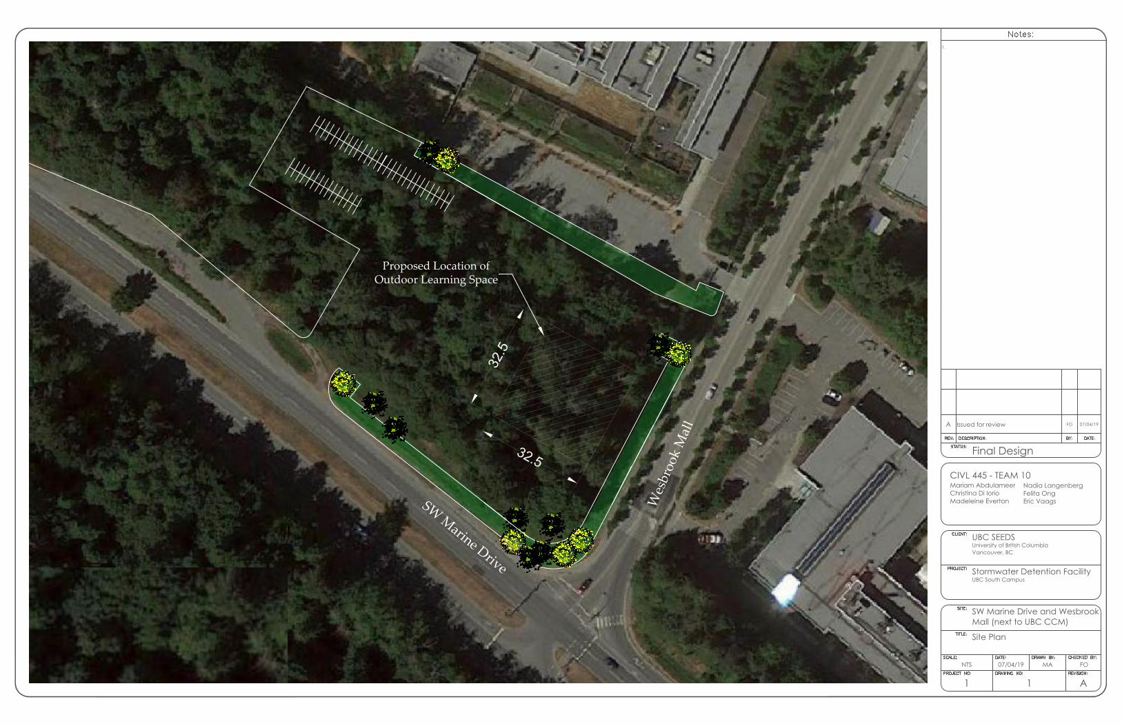
S
W
M
a
r
i
n
e
D
r
i
v
e
W
e
s
b
r
o
o
k
M
a
l
l
Proposed Location of
Outdoor Learning Space
3
2
.
5
3
2
.
5
A Issued for review FO 07/04/19
CIVL 445 - TEAM 10Mariam AbdulameerChristina Di IorioMadeleine Everton
Nadia LangenbergFelita OngEric Vaags
1.
A11
FOMA07/04/19NTS
Final Design
Site Plan
Mall (next to UBC CCM)SW Marine Drive and Wesbrook
UBC South CampusStormwater Detention Facility
Vancouver, BCUniversity of British ColumbiaUBC SEEDS

32500
32500
1250 (TYP.)
1250 (T
YP
.)
7500
7500
400 (TYP.)
400 (T
YP
.)
A Issued for review FO 07/04/19
B
C
CIVL 445 - TEAM 10Mariam AbdulameerChristina Di IorioMadeleine Everton
Nadia LangenbergFelita OngEric Vaags
1.
A21
FOFO07/04/191:5000
Final Design
Plan ViewOutdoor Learning Space -
Mall (next to UBC CCM)SW Marine Drive and Wesbrook
UBC South CampusStormwater Detention Facility
Vancouver, BCUniversity of British ColumbiaUBC SEEDS

GRAVEL-FILLED
FALSE BOTTOM
CONCRETE STEPS/RETAINING WALL
COMPACTED SOIL
400 (TYP.)
1000 (T
YP
.)
500
2000
7500
1250 (TYP.)
0.1M
2
ORIFICE
Ø
3
5
7
100
A Issued for review FO 07/04/19
B
C
CIVL 445 - TEAM 10Mariam AbdulameerChristina Di IorioMadeleine Everton
Nadia LangenbergFelita OngEric Vaags
1. Total depth (without false bottom): 5 mTotal depth (with false bottom): 7m
A31
FOFO07/04/191:2500
Final Design
Cross Section AOutdoor Learning Space -
Mall (next to UBC CCM)SW Marine Drive and Wesbrook
UBC South CampusStormwater Detention Facility
Vancouver, BCUniversity of British ColumbiaUBC SEEDS
Section A

CONCRETE STEPS/RETAINING WALL
COMPACTED SOIL
400 (TYP.)
1000 (T
YP
.)
500
2000
7500
1250 (TYP.)
100
GRAVEL-FILLED
FALSE BOTTOM
0.1M
2
ORIFICE
A Issued for review FO 07/04/19
B
C
CIVL 445 - TEAM 10Mariam AbdulameerChristina Di IorioMadeleine Everton
Nadia LangenbergFelita OngEric Vaags
1. Total depth (without false bottom): 5 mTotal depth (with false bottom): 7m
A41
FOFO07/04/191:2500
Final Design
Cross Section BOutdoor Learning Space -
Mall (next to UBC CCM)SW Marine Drive and Wesbrook
UBC South CampusStormwater Detention Facility
Vancouver, BCUniversity of British ColumbiaUBC SEEDS
Section B

100 (TYP.)
3000
4000
35000
16000
CONC.
COLUMN
STEEL TRUSS ROOF
A Issued for review FO 07/04/19
B
C
CIVL 445 - TEAM 10Mariam AbdulameerChristina Di IorioMadeleine Everton
Nadia LangenbergFelita OngEric Vaags
A61
FOFO07/04/191:2500
Final Design
Roof - Plan View
Mall (next to UBC CCM)SW Marine Drive and Wesbrook
UBC South CampusStormwater Detention Facility
Vancouver, BCUniversity of British ColumbiaUBC SEEDS
SECTION A

35000
40000
5571 (T
YP
.)
17000 17000
8993 4556 3452
CONC.
COLUMN
(TYP.)
STEEL W
BEAM (TYP.)
Steel HS
beams (TYP.)
STEEL W
BEAMS
(TYP.)
A Issued for review FO 07/04/19
B
C
CIVL 445 - TEAM 10Mariam AbdulameerChristina Di IorioMadeleine Everton
Nadia LangenbergFelita OngEric Vaags
1.
A51
FOFO07/04/191:2500
Final Design
Roof - Plan View
Mall (next to UBC CCM)SW Marine Drive and Wesbrook
UBC South CampusStormwater Detention Facility
Vancouver, BCUniversity of British ColumbiaUBC SEEDS

CONC. COLUMN (TYP.)
STEEL W BEAM
STEEL HS BEAM (TYP.)
STEEL W BEAM
STEEL HS BEAM
(BRACING)
5571 (TYP.)
A Issued for review FO 07/04/19
B
C
CIVL 445 - TEAM 10Mariam AbdulameerChristina Di IorioMadeleine Everton
Nadia LangenbergFelita OngEric Vaags
A71
FOFO07/04/191:2500
Final Design
Roof - Plan View
Mall (next to UBC CCM)SW Marine Drive and Wesbrook
UBC South CampusStormwater Detention Facility
Vancouver, BCUniversity of British ColumbiaUBC SEEDS
Section B

CONNECTION FROM COLUMN TO TOP BEAMS (TYP.)
50
60
52
320
48
48
9.5
11
39.5
W460X128
W360X382
L152X152X9.5
NOTE:
1. BOLT DIAMETER: 21 MM (ASTM A325)
2. USE 2 X L152X152X9.5 SECTIONS, ONE ON EACH
SIDE OF THE W360X382 SECTION
A Issued for review FO 07/04/19
B
C
CIVL 445 - TEAM 10Mariam AbdulameerChristina Di IorioMadeleine Everton
Nadia LangenbergFelita OngEric Vaags
A81
FOFO07/04/191:2500
Final Design
Structural Connection
Mall (next to UBC CCM)SW Marine Drive and Wesbrook
UBC South CampusStormwater Detention Facility
Vancouver, BCUniversity of British ColumbiaUBC SEEDS

350
15
00
10M STIRRUPS @
1000MM SPACING
ALONG SPAN25M @ 200MM
20M @ 200MM
200
15
00
10M STIRRUPS @
1000MM SPACING
ALONG SPAN25M @ 50MM
20M @ 50MM
STEPS / RETAINING STRUCTURES
ABOVE GWT BELOW GWT
A Issued for review FO 07/04/19
B
C
CIVL 445 - TEAM 10Mariam AbdulameerChristina Di IorioMadeleine Everton
Nadia LangenbergFelita OngEric Vaags
A91
FOFO07/04/191:2500
Final Design
Steps / Retaining Wall
Mall (next to UBC CCM)SW Marine Drive and Wesbrook
UBC South CampusStormwater Detention Facility
Vancouver, BCUniversity of British ColumbiaUBC SEEDS

20M @ 150 MM
20M @ 150 MM
500
3000
1000
FOOTINGS
EXTERIOR COLUMNS
20M @ 150 MM
20M @ 150 MM
500
2000
1000
INTERIOR COLUMNS
A Issued for review FO 07/04/19
B
C
CIVL 445 - TEAM 10Mariam AbdulameerChristina Di IorioMadeleine Everton
Nadia LangenbergFelita OngEric Vaags
A101
FOFO07/04/191:2500
Final Design
Footings
Mall (next to UBC CCM)SW Marine Drive and Wesbrook
UBC South CampusStormwater Detention Facility
Vancouver, BCUniversity of British ColumbiaUBC SEEDS