MACHINE SCREWS · 2008-08-25 · and drilled fillister head machine screws and gives cross recess...
31
1568 MACHINE SCREWS MACHINE SCREWS American National Standard Machine Screws and Machine Screw Nuts.—This Standard ANSI B18.6.3 covers both slotted and recessed head machine screws. Dimen- sions of various types of slotted machine screws, machine screw nuts, and header points are given in Tables 1 through 12. The Standard also covers flat trim head, oval trim head and drilled fillister head machine screws and gives cross recess dimensions and gaging dimensions for all types of machine screw heads. Information on metric machine screws B18.6.7M is given beginning on page 1577. Threads: Except for sizes 0000, 000, and 00, machine screw threads may be either Uni- fied Coarse (UNC) and Fine thread (UNF) Class 2A (see American Standard for Unified Screw Threads starting on page 1712) or UNRC and UNRF Series, at option of manufac- turer. Thread dimensions for sizes 0000, 000, and 00 are given in Table 7 on page 1573. Threads for hexagon machine screw nuts may be either UNC or UNF, Class 2B, and for square machine screw nuts are UNC Class 2B. Length of thread: Machine screws of sizes No. 5 and smaller with nominal lengths equal to 3 diameters and shorter have full form threads extending to within 1 pitch (thread) of the bearing surface of the head, or closer, if practicable. Nominal lengths greater than 3 diam- eters, up to and including 1 1 ⁄ 8 inch, have full form threads extending to within two pitches (threads) of the bearing surface of the head, or closer, if practicable. Unless otherwise spec- ified, screws of longer nominal length have a minimum length of full form thread of 1.00 inch.Machine screws of sizes No. 6 and larger with nominal length equal to 3 diameters and shorter have full form threads extending to within 1 pitch (thread) of the bearing sur- face of the head, or closer, if practicable. Nominal lengths greater than 3 diameters, up to and including 2 inches, have full form threads extending to within 2 pitches (threads) of the bearing surface of the head, or closer, if practicable. Screws of longer nominal length, unless otherwise specified, have a minimum length of full form thread of 1.50 inches. Table 1. Square and Hexagon Machine Screw Nuts ANSI B18.6.3-1972 (R1991) All dimensions in inches. Hexagon machine screw nuts have tops flat and chamfered. Diameter of top circle should be the maximum width across flats within a tolerance of minus 15 per cent. Bottoms are flat but may be chamfered if so specified. Square machine screw nuts have tops and bottoms flat without chamfer. Nom. Size Basic Dia. Basic F Max. F Min. F Max. G Min. G Max. G 1 Min. G 1 Max. H Min. H 0 0.0600 5 ⁄ 32 0.156 0.150 0.221 0.206 0.180 0.171 0.050 0.043 1 0.0730 5 ⁄ 32 0.156 0.150 0.221 0.206 0.180 0.171 0.050 0.043 2 0.0860 3 ⁄ 16 0.188 0.180 0.265 0.247 0.217 0.205 0.066 0.057 3 0.0990 3 ⁄ 16 0.188 0.180 0.265 0.247 0.217 0.205 0.066 0.057 4 0.1120 1 ⁄ 4 0.250 0.241 0.354 0.331 0.289 0.275 0.098 0.087 5 0.1250 5 ⁄ 16 0.312 0.302 0.442 0.415 0.361 0.344 0.114 0.102 6 0.1380 5 ⁄ 16 0.312 0.302 0.442 0.415 0.361 0.344 0.114 0.102 8 0.1640 11 ⁄ 32 0.344 0.332 0.486 0.456 0.397 0.378 0.130 0.117 10 0.1900 3 ⁄ 8 0.375 0.362 0.530 0.497 0.433 0.413 0.130 0.117 12 0.2160 7 ⁄ 16 0.438 0.423 0.619 0.581 0.505 0.482 0.161 0.148 1 ⁄ 4 0.2500 7 ⁄ 16 0.438 0.423 0.619 0.581 0.505 0.482 0.193 0.178 5 ⁄ 16 0.3125 9 ⁄ 16 0.562 0.545 0.795 0.748 0.650 0.621 0.225 0.208 3 ⁄ 8 0.3750 5 ⁄ 8 0.625 0.607 0.884 0.833 0.722 0.692 0.257 0.239 F H G F G 1 H 30 30 Optional; See Note
Transcript of MACHINE SCREWS · 2008-08-25 · and drilled fillister head machine screws and gives cross recess...

1568 MACHINE SCREWS
MACHINE SCREWS
American National Standard Machine Screws and Machine Screw Nuts.—Th isStandard ANSI B18.6.3 covers both slotted and recessed head machine screws. Dimen-sions of various types of slotted machine screws, machine screw nuts, and header pointsare given in Tables 1 through 12. The Standard also covers flat trim head, oval trim headand drilled fillister head machine screws and gives cross recess dimensions and gagingdimensions for all types of machine screw heads. Information on metric machine screwsB18.6.7M is given beginning on page1577.
Threads: Except for sizes 0000, 000, and 00, machine screw threads may be either Uni-fied Coarse (UNC) and Fine thread (UNF) Class 2A (see American Standard for UnifiedScrew Threads starting on page1712) or UNRC and UNRF Series, at option of manufac-turer. Thread dimensions for sizes 0000, 000, and 00 are given in Table 7 on page1573.
Threads for hexagon machine screw nuts may be either UNC or UNF, Class 2B, and forsquare machine screw nuts are UNC Class 2B.
Length of thread: Machine screws of sizes No. 5 and smaller with nominal lengths equalto 3 diameters and shorter have full form threads extending to within 1 pitch (thread) of thebearing surface of the head, or closer, if practicable. Nominal lengths greater than 3 diam-eters, up to and including 11⁄8 inch, have full form threads extending to within two pitches(threads) of the bearing surface of the head, or closer, if practicable. Unless otherwise spec-ified, screws of longer nominal length have a minimum length of full form thread of 1.00inch.Machine screws of sizes No. 6 and larger with nominal length equal to 3 diametersand shorter have full form threads extending to within 1 pitch (thread) of the bearing sur-face of the head, or closer, if practicable. Nominal lengths greater than 3 diameters, up toand including 2 inches, have full form threads extending to within 2 pitches (threads) of thebearing surface of the head, or closer, if practicable. Screws of longer nominal length,unless otherwise specified, have a minimum length of full form thread of 1.50 inches.
Table 1. Square and Hexagon Machine Screw Nuts ANSI B18.6.3-1972 (R1991)
All dimensions in inches. Hexagon machine screw nuts have tops flat and chamfered. Diameter oftop circle should be the maximum width across flats within a tolerance of minus 15 per cent. Bottomsare flat but may be chamfered if so specified. Square machine screw nuts have tops and bottoms flatwithout chamfer.
Nom.Size
BasicDia.
BasicF
Max.F
Min.F
Max.G
Min.G
Max.G1
Min.G1
Max.H
Min.H
0 0.0600 5⁄32 0.156 0.150 0.221 0.206 0.180 0.171 0.050 0.0431 0.0730 5⁄32 0.156 0.150 0.221 0.206 0.180 0.171 0.050 0.0432 0.0860 3⁄16 0.188 0.180 0.265 0.247 0.217 0.205 0.066 0.0573 0.0990 3⁄16 0.188 0.180 0.265 0.247 0.217 0.205 0.066 0.0574 0.1120 1⁄4 0.250 0.241 0.354 0.331 0.289 0.275 0.098 0.0875 0.1250 5⁄16 0.312 0.302 0.442 0.415 0.361 0.344 0.114 0.1026 0.1380 5⁄16 0.312 0.302 0.442 0.415 0.361 0.344 0.114 0.1028 0.1640 11⁄32 0.344 0.332 0.486 0.456 0.397 0.378 0.130 0.117
10 0.1900 3⁄8 0.375 0.362 0.530 0.497 0.433 0.413 0.130 0.11712 0.2160 7⁄16 0.438 0.423 0.619 0.581 0.505 0.482 0.161 0.148
1⁄4 0.2500 7⁄16 0.438 0.423 0.619 0.581 0.505 0.482 0.193 0.1785⁄16 0.3125 9⁄16 0.562 0.545 0.795 0.748 0.650 0.621 0.225 0.2083⁄8 0.3750 5⁄8 0.625 0.607 0.884 0.833 0.722 0.692 0.257 0.239
F H
G
F
G1
H
30 30
Optional;See Note

MACHINE SCREWS 1569
Diameter of body: The diameter of machine screw bodies is not less than Class 2A threadminimum pitch diameter nor greater than the basic major diameter of the thread. Cross-recessed trim head machine screws not threaded to the head have an 0.062 in. minimumlength shoulder under the head with diameter limits as specified in the dimensional tablesin the standard.
Designation: Machine screws are designated by the following data in the sequenceshown: Nominal size (number, fraction, or decimal equivalent); threads per inch; nominallength (fraction or decimal equivalent); product name, including head type and drivingprovision; header point, if desired; material; and protective finish, if required. For exam-ple:
1⁄4 − 20 × 11⁄4 Slotted Pan Head Machine Screw, Steel, Zinc Plated6 − 32 × 3⁄4 Type IA Cross Recessed Fillister Head Machine Screw, BrassMachine screw nuts are designated by the following data in the sequence shown: Nomi-
nal size (number, fraction, or decimal equivalent); threads per inch; product name; mate-rial; and protective finish, if required. For example:
10 − 24 Hexagon Machine Screw Nut, Steel, Zinc Plated0.138 − 32 Square Machine Screw Nut, Brass
Table 2. American National Standard Slotted 100-Degree Flat CountersunkHead Machine Screws ANSI B18.6.3-1972 (R1977)
All dimensions are in inches.
NominalSizea
or BasicScrew Dia.
a When specifying nominal size in decimals, zeros preceding the decimal point and in the fourth dec-imal place are omitted.
Head Dia., A HeadHeight,
H
SlotWidth,
J
SlotDepth,
TMax.,EdgeSharp
Min.,Edge
Roundedor Flat Ref. Max. Min. Max. Min.
0000 0.0210 0.043 0.037 0.009 0.008 0.005 0.008 0.004000 0.0340 0.064 0.058 0.014 0.012 0.008 0.011 0.00700 0.0470 0.093 0.085 0.020 0.017 0.010 0.013 0.0080 0.0600 0.119 0.096 0.026 0.023 0.016 0.013 0.0081 0.0730 0.146 0.120 0.031 0.026 0.019 0.016 0.0102 0.0860 0.172 0.143 0.037 0.031 0.023 0.019 0.0123 0.0990 0.199 0.167 0.043 0.035 0.027 0.022 0.0144 0.1120 0.225 0.191 0.049 0.039 0.031 0.024 0.0176 0.1380 0.279 0.238 0.060 0.048 0.039 0.030 0.0228 0.1640 0.332 0.285 0.072 0.054 0.045 0.036 0.027
10 0.1900 0.385 0.333 0.083 0.060 0.050 0.042 0.0311⁄4 0.2500 0.507 0.442 0.110 0.075 0.064 0.055 0.042
5⁄16 0.3125 0.635 0.556 0.138 0.084 0.072 0.069 0.0533⁄8 0.3750 0.762 0.670 0.165 0.094 0.081 0.083 0.065
A
L
H
T
J99 101

1570 MACHINE SCREWS
Table 3. American National Standard Slotted Flat Countersunk Head and Close Tolerance 100-Degree Flat Countersunk Head Machine Screws
ANSI B18.6.3-1972 (R1991)
All dimensions are in inches.
SLOTTED FLAT COUNTERSUNK HEAD TYPE
NominalSizea or Basic
Screw Dia.
a When specifying nominal size in decimals, zeros preceding the decimal point and in the fourth dec-imal place are omitted.
Max.,Lb
b These lengths or shorter are undercut.
Head Dia., A HeadHeight, H
SlotWidth, J
SlotDepth, TMax., Edge
SharpMin.,Edgec
c May be rounded or flat.
Ref. Max. Min. Max. Min.
0000 0.0210 .... 0.043 0.037 0.011 0.008 0.004 0.007 0.003000 0.0340 .... 0.064 0.058 0.016 0.011 0.007 0.009 0.00500 0.0470 .... 0.093 0.085 0.028 0.017 0.010 0.014 0.0090 0.0600 1⁄8 0.119 0.099 0.035 0.023 0.016 0.015 0.010
1 0.0730 1⁄8 0.146 0.123 0.043 0.026 0.019 0.019 0.012
2 0.0860 1⁄8 0.172 0.147 0.051 0.031 0.023 0.023 0.015
3 0.0990 1⁄8 0.199 0.171 0.059 0.035 0.027 0.027 0.017
4 0.1120 3⁄16 0.225 0.195 0.067 0.039 0.031 0.030 0.020
5 0.1250 3⁄16 0.252 0.220 0.075 0.043 0.035 0.034 0.022
6 0.1380 3⁄16 0.279 0.244 0.083 0.048 0.039 0.038 0.024
8 0.1640 1⁄4 0.332 0.292 0.100 0.054 0.045 0.045 .029
10 0.1900 5⁄16 0.385 0.340 0.116 0.060 0.050 0.053 0.034
12 0.2160 3⁄8 0.438 0.389 0.132 0.067 0.056 0.060 0.0391⁄4 0.2500 7⁄16 0.507 0.452 0.153 0.075 0.064 0.070 0.046
5⁄16 0.3125 1⁄2 0.635 0.568 0.191 0.084 0.072 0.088 0.0583⁄8 0.3750 9⁄16 0.762 0.685 0.230 0.094 0.081 0.106 0.070
7⁄16 0.4375 5⁄8 0.812 0.723 0.223 0.094 0.081 0.103 .0661⁄2 0.5000 3⁄4 0.875 0.775 0.223 0.106 0.091 0.103 0.065
9⁄16 0.5625 … 1.000 0.889 0.260 0.118 0.102 0.120 0.0775⁄8 0.6250 … 1.125 1.002 0.298 0.133 0.116 0.137 0.0883⁄4 0.7500 … 1.375 1.230 0.372 0.149 0.131 0.171 0.111
CLOSE TOLERANCE 100-DEGREE FLAT COUNTERSUNK HEAD TYPE
NominalSizea
or BasicScrew Dia.
Head Diameter, A HeadHeight,
H
Slot Width,
J
SlotDepth,
TMax.,EdgeSharp
Min.,Edgec Ref. Max. Min. Max. Min.
4 0.1120 0.225 0.191 0.049 0.039 0.031 0.024 0.0176 0.1380 0.279 0.238 0.060 0.048 0.039 0.030 0.0228 0.1640 0.332 0.285 0.072 0.054 0.045 0.036 0.027
10 0.1900 0.385 0.333 0.083 0.060 0.050 0.042 0.0311⁄4 0.2500 0.507 0.442 0.110 0.075 0.064 0.055 0.042
5⁄16 0.3125 0.635 0.556 0.138 0.084 0.072 0.069 0.0533⁄8 0.3750 0.762 0.670 0.165 0.094 0.081 0.083 0.065
7⁄16 0.4375 0.890 0.783 0.193 0.094 0.081 0.097 0.0761⁄2 0.5000 1.017 0.897 0.221 0.106 0.091 0.111 0.088
9⁄16 0.5625 1.145 1.011 0.249 0.118 0.102 0.125 0.0995⁄8 0.6250 1.272 1.124 0.276 0.133 0.116 0.139 0.111

MACHINE SCREWS 1571
Table 4. American National Standard Slotted Undercut Flat Countersunk Head and Plain and Slotted Hex Washer Head Machine Screws ANSI B18.6.3-1972 (R1991)
All dimensions are in inches.
SLOTTED UNDERCUT FLAT COUNTERSUNK HEAD TYPE
NominalSizea or Basic
Screw Dia.
a When specifying nominal size in decimals, zeros preceding the decimal point and in the fourth dec-imal place are omitted.
Max.,Lb
b These lengths or shorter are undercut.
Head Dia., A HeadHeight,
H
SlotWidth,
J
SlotDepth,
TMax.,EdgeSharp
Min., EdgeRnded.or Flat Max. Min. Max. Min. Max. Min.
0 0.0600 1⁄8 0.119 0.099 0.025 0.018 0.023 0.016 0.011 0.007
1 0.0730 1⁄8 0.146 0.123 0.031 0.023 0.026 0.019 0.014 0.009
2 0.0860 1⁄8 0.172 0.147 0.036 0.028 0.031 0.023 0.016 0.011
3 0.0990 1⁄8 0.199 0.171 0.042 0.033 0.035 0.027 0.019 0.012
4 0.1120 3⁄16 0.225 0.195 0.047 0.038 0.039 0.031 0.022 0.014
5 0.1250 3⁄16 0.252 0.220 0.053 0.043 0.043 0.035 0.024 0.016
6 0.1380 3⁄16 0.279 0.244 0.059 0.048 0.048 0.039 0.027 0.017
8 0.1640 1⁄4 0.332 0.292 0.070 0.058 0.054 0.045 0.032 0.021
10 0.1900 5⁄16 0.385 0.340 0.081 0.068 0.060 0.050 0.037 0.024
12 0.2160 3⁄8 0.438 0.389 0.092 0.078 0.067 0.056 0.043 0.0281⁄4 0.2500 7⁄16 0.507 0.452 0.107 0.092 0.075 0.064 0.050 0.0325⁄16 0.3125 1⁄2 0.635 0.568 0.134 0.116 0.084 0.072 0.062 0.0413⁄8 0.3750 9⁄16 0.762 0.685 0.161 0.140 0.094 0.081 0.075 0.0497⁄16 0.4375 5⁄8 0.812 0.723 0.156 0.133 0.094 0.081 0.072 0.0451⁄2 0.5000 3⁄4 0.875 0.775 0.156 0.130 0.106 0.091 0.072 0.046
PLAIN AND SLOTTED HEX WASHER HEAD TYPES
NominalSizea
or BasicScrew Dia.
WidthAcross Flats,
A
WidthAcross-Corn.,
W
HeadHeight,
H
WasherDia.,
B
WasherThick.,
U
Slota
Width,J
a Unless otherwise specified, hexagon washer head machine screws are not slotted.
Slota
Depth,T
Max. Min. Min. Max. Min. Max. Min. Max. Min. Max. Min. Max. Min.
2 0.0860 0.125 0.120 0.134 0.050 0.040 0.166 0.154 0.016 0.010…. …. …. ….3 0.0990 0.125 0.120 0.134 0.055 0.044 0.177 0.163 0.016 0.010…. …. …. ….4 0.1120 0.188 0.181 0.202 0.060 0.049 0.243 0.225 0.019 0.011 0.039 0.031 0.042 0.0255 0.1250 0.188 0.181 0.202 0.070 0.058 0.260 0.240 0.025 0.015 0.043 0.035 0.049 0.0306 0.1380 0.250 0.244 0.272 0.093 0.080 0.328 0.302 0.025 0.015 0.048 0.039 0.053 0.0338 0.1640 0.250 0.244 0.272 0.110 0.096 0.348 0.322 0.031 0.019 0.054 0.045 0.074 0.052
10 0.1900 0.312 0.305 0.340 0.120 0.105 0.414 0.384 0.031 0.019 0.060 0.050 0.080 0.05712 0.2160 0.312 0.305 0.340 0.155 0.139 0.432 0.398 0.039 0.022 0.067 0.056 0.103 0.077
1⁄4 0.2500 0.375 0.367 0.409 0.190 0.172 0.520 0.480 0.050 0.030 0.075 0.064 0.111 0.0835⁄16 0.3125 0.500 0.489 0.545 0.230 0.208 0.676 0.624 0.055 0.035 0.084 0.072 0.134 0.1003⁄8 0.3750 0.562 0.551 0.614 0.295 0.270 0.780 0.720 0.063 0.037 0.094 0.081 0.168 0.131

1572 MACHINE SCREWS
Table 5. American National Standard Slotted Truss Head and Plain and Slotted Hexagon Head Machine Screws ANSI B18.6.3-1972 (R1991)
All dimensions are in inches.
SLOTTED TRUSS HEAD TYPE
NominalSizea or Basic
Screw Dia.
a Where specifying nominal size in decimals, zeros preceding decimal points and in the fourth deci-mal place are omitted.
Head Dia.,A
Head Height,H
Head Radius,R
Slot Width,J
Slot Depth,T
Max. Min. Max. Min. Max. Max. Min. Max. Min.
0000 0.0210 0.049 0.043 0.014 0.010 0.032 0.009 0.005 0.009 0.005000 0.0340 0.077 0.071 0.022 0.018 0.051 0.013 0.009 0.013 0.00900 0.0470 0.106 0.098 0.030 0.024 0.070 0.017 0.010 0.018 0.0120 0.0600 0.131 0.119 0.037 0.029 0.087 0.023 0.016 0.022 0.0141 0.0730 0.164 0.149 0.045 0.037 0.107 0.026 0.019 0.027 0.0182 0.0860 0.194 0.180 0.053 0.044 0.129 0.031 0.023 0.031 0.0223 0.0990 0.226 0.211 0.061 0.051 0.151 0.035 0.027 0.036 0.0264 0.1120 0.257 0.241 0.069 0.059 0.169 0.039 0.031 0.040 0.0305 0.1250 0.289 0.272 0.078 0.066 0.191 0.043 0.035 0.045 0.0346 0.1380 0.321 0.303 0.086 0.074 0.211 0.048 0.039 0.050 0.0378 0.1640 0.384 0.364 0.102 0.088 0.254 0.054 0.045 0.058 0.045
10 0.1900 0.448 0.425 0.118 0.103 0.283 0.060 0.050 0.068 0.05312 0.2160 0.511 0.487 0.134 0.118 0.336 0.067 0.056 0.077 0.061
1⁄4 0.2500 0.573 0.546 0.150 0.133 0.375 0.075 0.064 0.087 0.0705⁄16 0.3125 0.698 0.666 0.183 0.162 0.457 0.084 0.072 0.106 0.0853⁄8 0.3750 0.823 0.787 0.215 0.191 0.538 0.094 0.081 0.124 0.1007⁄16 0.4375 0.948 0.907 0.248 0.221 0.619 0.094 0.081 0.142 0.1161⁄2 0.5000 1.073 1.028 0.280 0.250 0.701 0.106 0.091 0.161 0.1319⁄16 0.5625 1.198 1.149 0.312 0.279 0.783 0.118 0.102 0.179 0.1465⁄8 0.6250 1.323 1.269 0.345 0.309 0.863 0.133 0.116 0.196 0.1623⁄4 0.7500 1.573 1.511 0.410 0.368 1.024 0.149 0.131 0.234 0.182
PLAIN AND SLOTTED HEXAGON HEAD TYPES
NominalSizea
or BasicScrew Dia.
Regular Head Large HeadHead
Height, HSlota
Width, J
a Unless otherwise specified, hexagon head machine screws are not slotted.
Slota
Depth, TWidthAcrossFlats, A
AcrossCorn., W
WidthAcrossFlats, A
AcrossCorn., W
Max. Min. Min. Max. Min. Min. Max. Min. Max. Min. Max. Min.
1 .0730 .125 .120 .134 .... .... .... .044 .036 .... .... .... …2 0.0860 .125 .120 .134 .... .... .... .050 .040 .... .... .... …3 0.0990 .188 .181 .202 .... .... .... .055 .044 .... .... .... …4 0.1120 .188 .181 .202 .219 .213 .238 .060 .049 .039 .031 .036 .025 0.1250 .188 .181 .202 .250 .244 .272 .070 .058 .043 .035 .042 .036 0.1380 .250 .244 .272 .... .... .... .093 .080 .048 .039 .046 .038 0.1640 .250 .244 .272 .312 .305 .340 .110 .096 .054 .045 .066 .05
10 0.1900 .312 .305 .340 .... .... .... .120 .105 .060 .050 .072 .05712 0.2160 .312 .305 .340 .375 .367 .409 .155 .139 .067 .056 .093 .07
1⁄4 0.2500 .375 .367 .409 .438 .428 .477 .190 .172 .075 .064 .101 .085⁄16 0.3125 .500 .489 .545 .... .... .... .230 .208 .084 .072 .122 .103⁄8 0.3750 .562 .551 .614 .... .... .... .295 .270 .094 .081 .156 .13

MACHINE SCREWS 1573
Table 6. American National Standard Slotted Pan Head Machine Screws ANSI B18.6.3-1972 (R1991)
All dimensions are in inches.
Table 7. Nos. 0000, 000 and 00 Threads ANSI B18.6.3-1972 (R1991) Appendix
All dimensions are in inches.
NominalSizea
or BasicScrew Dia.
a Where specifying nominal size in decimals, zeros preceding decimal and in the fourth decimalplace are omitted.
HeadDia.,
A
HeadHeight,
H
HeadRadius,
R
SlotWidth,
J
SlotDepth,
T
Max. Min. Max. Min. Max. Max. Min. Max. Min.
0000 0.0210 .042 .036 .016 .010 .007 .008 .004 .008 .004000 0.0340 .066 .060 .023 .017 .010 .012 .008 .012 .00800 0.0470 .090 .082 .032 .025 .015 .017 .010 .016 .0100 0.0600 .116 .104 .039 .031 .020 .023 .016 .022 .0141 0.0730 .142 .130 .046 .038 .025 .026 .019 .027 .0182 0.0860 .167 .155 .053 .045 .035 .031 .023 .031 .0223 0.0990 .193 .180 .060 .051 .037 .035 .027 .036 .0264 0.1120 .219 .205 .068 .058 .042 .039 .031 .040 .0305 0.1250 .245 .231 .075 .065 .044 .043 .035 .045 .0346 0.1380 .270 .256 .082 .072 .046 .048 .039 .050 .0378 0.1640 .322 .306 .096 .085 .052 .054 .045 .058 .045
10 0.1900 .373 .357 .110 .099 .061 .060 .050 .068 .05312 0.2160 .425 .407 .125 .112 .078 .067 .056 .077 .061
1⁄4 0.2500 .492 .473 .144 .130 .087 .075 .064 .087 .0705⁄16 0.3125 .615 .594 .178 .162 .099 .084 .072 .106 .0853⁄8 0.3750 .740 .716 .212 .195 .143 .094 .081 .124 .1007⁄16 0.4375 .863 .837 .247 .228 .153 .094 .081 .142 .1161⁄2 0.5000 .987 .958 .281 .260 .175 .106 .091 .161 .1319⁄16 0.5625 1.041 1.000 .315 .293 .197 .118 .102 .179 .1465⁄8 0.6250 1.172 1.125 .350 .325 .219 .133 .116 .197 .1623⁄4 0.7500 1.435 1.375 .419 .390 .263 .149 .131 .234 .192
NominalSizea
andThreadsPer Inch
a Where specifying nominal size in decimals, zeros preceding decimal and in the fourth decimalplace are omitted.
Ser
ies
De
sig
na
t. Externalb
b There is no allowance provided on the external threads.
Internalc
c The minor diameter limits for internal threads are not specified, they being determined by theamount of thread engagement necessary to satisfy the strength requirements and tapping performancein the intended application.
Cla
ss
MajorDiameter
PitchDiameter Minor
Dia. Cla
ss
PitchDiameter
MajorDia.
Max. Min. Max. Min. Tol. Min. Max. Tol. Min.
0000-160 or0.0210-160
NS 2 .0210 .0195 .0169 .0158 .0011 .0128 2 .0169 .0181 .0012 .0210
000-120 or0.0340-120
NS 2 .0340 .0325 .0286 0.272 .0014 .0232 2 .0286 .0300 .0014 .034
00-90 or0.0470-90
NS 2 .0470 .0450 .0398 .0382 .0016 .0326 2 .0398 .0414 .0016 .047
00-96 or0.0470-96
NS 2 .0470 .0450 .0402 .0386 .0016 .0334 2 .0402 .0418 .0016 .047
1574 MACHINE SCREWS
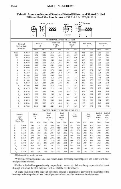
All dimensions are in inches.1Where specifying nominal size in decimals, zeros preceding decimal points and in the fourth dec-
imal place are omitted.2Drilled hole shall be approximately perpendicular to the axis of slot and may be permitted to break
through bottom of the slot. Edges of the hole shall be free from burrs.3A slight rounding of the edges at periphery of head is permissible provided the diameter of the
bearing circle is equal to no less than 90 per cent of the specified minimum head diameter.
Table 8. American National Standard Slotted Fillister and Slotted Drilled Fillister Head Machine Screws ANSI B18.6.3-1972 (R1991)
SLOTTED FILLISTER HEAD TYPE
NominalSize1 or Basic
Screw Dia.
Head Dia.,A
Head SideHeight,
H
Total HeadHeight,
O
Slot Width,J
Slot Depth,T
Max. Min. Max. Min. Max. Min. Max Min. Max. Min.
0000 0.0210 .038 .032 .019 .011 .025 .15 .008 .004 .012 .006000 0.0340 .059 .053 .029 .021 .035 .027 .012 .006 .017 .01100 0.0470 .082 .072 .037 .028 .047 .039 .017 .010 .022 .0150 0.0600 .096 .083 .043 .038 .055 .047 .023 .016 .025 .0151 0.0730 .118 .104 .053 .045 .066 .058 .026 .019 .031 .0202 0.0860 .140 .124 .062 .053 .083 .066 .031 .023 .037 .0253 0.0990 .161 .145 .070 .061 .095 .077 .035 .027 .043 .0304 0.1120 .183 .166 .079 .069 .107 .088 .039 .031 .048 .0355 0.1250 .205 .187 .088 .078 .120 .100 .043 .035 .054 .0406 0.1380 .226 .208 .096 .086 .132 .111 .048 .039 .060 .0458 0.1640 .270 .250 .113 .102 .156 .133 .054 .045 .071 .054
10 0.1900 .313 .292 .130 .118 .180 .156 .060 .050 .083 .06412 0.2160 .357 .334 .148 .134 .205 .178 .067 .056 .094 .074
1⁄4 0.2500 .414 .389 .170 .155 .237 .207 .075 .064 .109 .0875⁄16 0.3125 .518 .490 .211 .194 .295 .262 .084 .072 .137 .1103⁄8 0.3750 .622 .590 .253 .233 .355 .315 .094 .081 .164 .1337⁄16 0.4375 .625 .589 .265 .242 .368 .321 .094 .081 .170 .1351⁄2 0.5000 .750 .710 .297 .273 .412 .362 .106 .091 .190 .1519⁄16 0.5625 .812 .768 .336 .308 .466 .410 .118 .102 .214 .1725⁄8 0.6250 .875 .827 .375 .345 .521 .461 .133 .116 .240 .1933⁄4 0.7500 1.000 .945 .441 .406 .612 .542 .149 .131 .281 .226
SLOTTED DRILLED FILLISTER HEAD TYPE
NominalSize1
or BasicScrew Dia.
HeadDia.,
A
HeadSide
Height,H
TotalHead
Height,O
SlotWidth,
J
SlotDepth,
T
DrilledHole
Locat.,E
DrilledHole.Dia.,
F
Max. Min. Max. Min. Max. Min. Max. Min. Max. Min. Basic Basic
2 0.0860 .140 .124 .062 .055 .083 .070 .031 .023 .030 .022 .026 .0313 0.0990 .161 .145 .070 .064 .095 .082 .035 .027 .034 .026 .030 .0374 0.1120 .183 .166 .079 .072 .107 .094 .039 .031 .038 .030 .035 .0375 0.1250 .205 .187 .088 .081 .120 .106 .043 .035 .042 .033 .038 .0466 0.1380 .226 .208 .096 .089 .132 .118 .048 .039 .045 .035 .043 .0468 0.1640 .270 .250 .113 .106 .156 .141 .054 .045 .065 .054 .043 .04610 0.1900 .313 .292 .130 .123 .180 .165 .060 .050 .075 .064 .043 .04612 0.2160 .357 .334 .148 .139 .205 .188 .067 .056 .087 .074 .053 .046
1⁄4 0.2500 .414 .389 .170 .161 .237 .219 .075 .064 .102 .087 .062 .0625⁄16 0.3125 .518 .490 .211 .201 .295 .276 .084 .072 .130 .110 .078 .0703⁄8 0.3750 .622 .590 .253 .242 .355 .333 .094 .081 .154 .134 .094 .070

MACHINE SCREWS 1575
Table 9. American National Standard Slotted Oval Countersunk Head Machine Screws ANSI B18.6.3-1972 (R1991)
All dimensions are in inches.
Table 10. American National Standard Header Points for Machine Screws before Threading ANSI B18.6.3-1972 (R1991)
All dimensions in inches. Edges of point may be rounded and end of point need not be flat nor per-pendicular to shank. Machine screws normally have plain sheared ends but when specified may haveheader points, as shown above.
NominalSizea
or BasicScrew Dia.
a When specifying nominal size in decimals, zeros preceding decimal points and in the fourth deci-mal place are omitted.
MaxLb
b These lengths or shorter are undercut.
Head Dia.,A
HeadSide
Height,H,
Total HeadHeight,
O
SlotWidth,
J
SlotDepth,
TMax.,EdgeSharp
Min.,Edge
Rnded.or Flat Ref. Max. Min. Max. Min. Max. Min.
00 0.0470 … .093 .085 .028 .042 .034 .017 .010 .023 .0160 0.0600 1⁄8 .119 .099 .035 .056 .041 .023 .016 .030 .0251 0.0730 1⁄8 .146 .123 .043 .068 .052 .026 .019 .038 .0312 0.0860 1⁄8 .172 .147 .051 .080 .063 .031 .023 .045 .0373 0.0990 1⁄8 .199 .171 .059 .092 .073 .035 .027 .052 .0434 0.1120 3⁄16 .225 .195 .067 .104 .084 .039 .031 .059 .0495 0.1250 3⁄16 .252 .220 .075 .116 .095 .043 .035 .067 .0556 0.1380 3⁄16 .279 .244 .083 .128 .105 .048 .039 .074 .0608 0.1640 1⁄4 .332 .292 .100 .152 .126 .054 .045 .088 .07210 0.1900 5⁄16 .385 .340 .116 .176 .148 .060 .050 .103 .08412 0.2160 3⁄8 .438 .389 .132 .200 .169 .067 .056 .117 .096
1⁄4 0.2500 7⁄16 .507 .452 .153 .232 .197 .075 .064 .136 .1125⁄16 0.3125 1⁄2 .635 .568 .191 .290 .249 .084 .072 .171 .1413⁄8 0.3750 9⁄16 .762 .685 .230 .347 .300 .094 .081 .206 .1707⁄16 0.4375 5⁄8 .812 .723 .223 .345 .295 .094 .081 .210 .1741⁄2 0.5000 3⁄4 .875 .775 .223 .354 .299 .106 .091 .216 .1769⁄16 0.5625 … 1.000 .889 .260 .410 .350 .118 .102 .250 .2075⁄8 0.6250 … 1.125 1.002 .298 .467 .399 .133 .116 .285 .2353⁄4 0.7500 … 1.375 1.230 .372 .578 .497 .149 .131 .353 .293
Nom.Size
Threadsper Inch
Max.P
Min.P
Max.L
1024 0.125 0.112 11⁄4
32 0.138 0.124 11⁄4
Nom.Size.
Threadsper Inch
Max.P
Min.P
Max.L
1224 0.149 0.134 13⁄828 0.156 0.141 13⁄8
256 0.057 0.050 1⁄2 1⁄4
20 0.170 0.153 11⁄264 0.060 0.053 1⁄2 28 0.187 0.169 11⁄2
440 0.074 0.065 1⁄2 5⁄16
18 0.221 0.200 11⁄248 0.079 0.070 1⁄2 24 0.237 0.215 11⁄2
540 0.086 0.076 1⁄2 3⁄8
16 0.270 0.244 11⁄244 0.088 0.079 1⁄2 24 0.295 0.267 11⁄2
632 0.090 0.080 3⁄4 7⁄16
14 0.316 0.287 11⁄240 0.098 0.087 3⁄4 20 0.342 0.310 11⁄2
832 0.114 0.102 1
1⁄213 0.367 0.333 11⁄2
36 0.118 0.106 1 20 0.399 0.362 11⁄2

1576 MACHINE SCREWS
Table 11. American National Standard Slotted Binding Head and Slotted Undercut Oval Countersunk Head Machine Screws ANSI B18.6.3-1972 (R1991)
All dimensions are in inches.
SLOTTED BINDING HEAD TYPE
NominalSizea
or BasicScrew Dia.
a Where specifying nominal size in decimals, zeros preceding decimal points and in the fourth deci-mal place are omitted.
HeadDia.,
A
Total HeadHeight,
O
Head OvalHeight,
F
SlotWidth,
J
SlotDepth,
T
Undercutb
Dia.,U
b Unless otherwise specified, slotted binding head machine screws are not undercut.
Undercutb
Depth,X
Max. Min. Max. Min. Max. Min. Max. Min. Max. Min. Max. Min. Max. Min.
0000 0.0210 .046 .040 .014 .009 .006 .003 .008 .004 .009 .005… … … …000 0.0340 .073 .067 .021 .015 .008 .005 .012 .006 .013 .009… … … …00 0.0470 .098 .090 .028 .023 .011 .007 .017 .010 .018 .012… … … …0 0.0600 .126 .119 .032 .026 .012 .008 .023 .016 .018 .009 .098 .086 .007 .0021 0.0730 .153 .145 .041 .035 .015 .011 .026 .019 .024 .014 .120 .105 .008 .0032 0.0860 .181 .171 .050 .043 .018 .013 .031 .023 .030 .020 .141 .124 .010 .0053 0.0990 .208 .197 .059 .052 .022 .016 .035 .027 .036 .025 .162 .143 .011 .0064 0.1120 .235 .223 .068 .061 .025 .018 .039 .031 .042 .030 .184 .161 .012 .0075 0.1250 .263 .249 .078 .069 .029 .021 .043 .035 .048 .035 .205 .180 .014 .0096 0.1380 .290 .275 .087 .078 .032 .024 .048 .039 .053 .040 .226 .199 .015 .0108 0.1640 .344 .326 .105 .095 .039 .029 .054 .045 .065 .050 .269 .236 .017 .012
10 0.1900 .399 .378 .123 .112 .045 .034 .060 .050 .077 .060 .312 .274 .020 .01512 0.2160 .454 .430 .141 .130 .052 .039 .067 .056 .089 .070 .354 .311 .023 .018
1⁄4 0.2500 .525 .498 .165 .152 .061 .046 .075 .064 .105 .084 .410 .360 .026 .0215⁄16 0.3125 .656 .622 .209 .194 .077 .059 .084 .072 .134 .108 .513 .450 .032 .0273⁄8 0.3750 .788 .746 .253 .235 .094 .071 .094 .081 .163 .132 .615 .540 .039 .034
SLOTTED UNDERCUT OVAL COUNTERSUNK HEAD TYPES
NominalSizea
or BasicScrew Dia.
Max.La
a These lengths or shorter are undercut.
Head Dia.,A
HeadSide
Height,H
TotalHead
Height,O
SlotWidth,
J
SlotDepth,
TMax.,EdgeSharp
Min.,Edge
Rnded.or Flat Ref. Max. Min. Max. Min. Max. Min.
0 0.0600 1⁄8 .119 .099 .025 .046 .033 .023 .016 .028 .022
1 0.0730 1⁄8 .146 .123 .031 .056 .042 .026 .019 .034 .027
2 0.0860 1⁄8 .172 .147 .036 .065 .050 .031 .023 .040 .033
3 0.0990 1⁄8 .199 .171 .042 .075 .059 .035 .027 .047 .038
4 0.1120 3⁄16 .225 .195 .047 .084 .067 .039 .031 .053 .043
5 0.1250 3⁄16 .252 .220 .053 .094 .076 .043 .035 .059 .048
6 0.1380 3⁄16 .279 .244 .059 .104 .084 .048 .039 .065 .053
8 0.1640 1⁄4 .332 .292 .070 .123 .101 .054 .045 .078 .064
10 0.1900 5⁄16 .385 .340 .081 .142 .118 .060 .050 .090 .074
12 0.2160 3⁄8 .438 .389 .092 .161 .135 .067 .056 .103 .0851⁄4 0.2500 7⁄16 .507 .452 .107 .186 .158 .075 .064 .119 .0985⁄16 0.3125 1⁄2 .635 .568 .134 .232 .198 .084 .072 .149 .1243⁄8 0.3750 9⁄16 .762 .685 .161 .278 .239 .094 .081 .179 .1497⁄16 0.4375 5⁄8 .812 .723 .156 .279 .239 .094 .081 .184 .1541⁄2 0.5000 3⁄4 .875 .775 .156 .288 .244 .106 .091 .204 .169
MACHINE SCREWS 1577
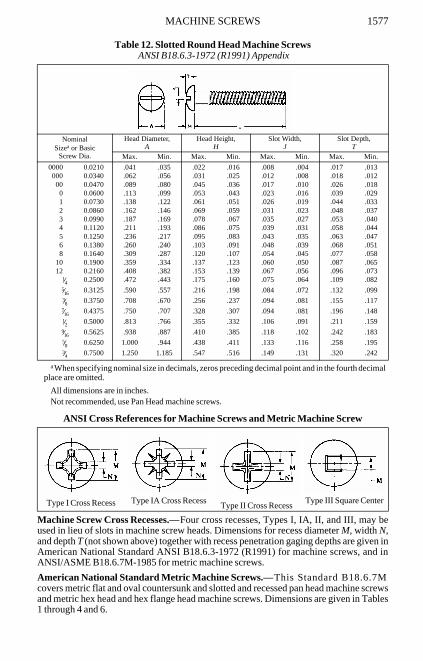
Table 12. Slotted Round Head Machine Screws ANSI B18.6.3-1972 (R1991) Appendix
All dimensions are in inches.Not recommended, use Pan Head machine screws.
ANSI Cross References for Machine Screws and Metric Machine Screw
Machine Screw Cross Recesses.—Four cross recesses, Types I, IA, II, and III, may beused in lieu of slots in machine screw heads. Dimensions for recess diameter M, width N,and depth T (not shown above) together with recess penetration gaging depths are given inAmerican National Standard ANSI B18.6.3-1972 (R1991) for machine screws, and inANSI/ASME B18.6.7M-1985 for metric machine screws.
American National Standard Metric Machine Screws.—This Standard B18.6.7Mcovers metric flat and oval countersunk and slotted and recessed pan head machine screwsand metric hex head and hex flange head machine screws. Dimensions are given in Tables1 through 4 and 6.
NominalSizea or Basic
Screw Dia.
a When specifying nominal size in decimals, zeros preceding decimal point and in the fourth decimalplace are omitted.
Head Diameter,A
Head Height,H
Slot Width,J
Slot Depth,T
Max. Min. Max. Min. Max. Min. Max. Min.
0000 0.0210 .041 .035 .022 .016 .008 .004 .017 .013000 0.0340 .062 .056 .031 .025 .012 .008 .018 .01200 0.0470 .089 .080 .045 .036 .017 .010 .026 .0180 0.0600 .113 .099 .053 .043 .023 .016 .039 .0291 0.0730 .138 .122 .061 .051 .026 .019 .044 .0332 0.0860 .162 .146 .069 .059 .031 .023 .048 .0373 0.0990 .187 .169 .078 .067 .035 .027 .053 .0404 0.1120 .211 .193 .086 .075 .039 .031 .058 .0445 0.1250 .236 .217 .095 .083 .043 .035 .063 .0476 0.1380 .260 .240 .103 .091 .048 .039 .068 .0518 0.1640 .309 .287 .120 .107 .054 .045 .077 .058
10 0.1900 .359 .334 .137 .123 .060 .050 .087 .06512 0.2160 .408 .382 .153 .139 .067 .056 .096 .073
1⁄4 0.2500 .472 .443 .175 .160 .075 .064 .109 .0825⁄16 0.3125 .590 .557 .216 .198 .084 .072 .132 .0993⁄8 0.3750 .708 .670 .256 .237 .094 .081 .155 .1177⁄16 0.4375 .750 .707 .328 .307 .094 .081 .196 .1481⁄2 0.5000 .813 .766 .355 .332 .106 .091 .211 .1599⁄16 0.5625 .938 .887 .410 .385 .118 .102 .242 .1835⁄8 0.6250 1.000 .944 .438 .411 .133 .116 .258 .1953⁄4 0.7500 1.250 1.185 .547 .516 .149 .131 .320 .242
Type I Cross Recess Type IA Cross RecessType II Cross Recess
Type III Square Center

1578 MACHINE SCREWS
Table 1. American National Standard Thread Lengths for Metric Machine Screws ANSI/ASME B18.6.7M-1985
All dimensions in millimeters.
Pan, Hex, and Hex Flange Head Screws
Flat and Oval Countersunk Head Screws
Heat-Treated Recessed Flat Countersunk Head Screws
NominalScrewSizeand
ThreadPitch
L LUS LU L LUS LUL L B
Nomi-nal
ScrewLengthEqualto or
Shorterthana
a The length tolerances for metric machine screws are: up to 3 mm, incl., ± 0.2 mm; over 3 to 10 mm,incl., ± 0.3 mm; over 10 to 16 mm, incl., ± 0.4 mm; over 16 to 50 mm, incl., ± 0.5 mm; over 50 mm, ±1.0 mm.
UnthreadedLengthb
b Unthreaded lengths LU and LUS represent the distance, measured parallel to the axis of screw, fromthe underside of the head to the face of a nonchamfered or noncounterbored standard GO thread ringgage assembled by hand as far as the thread will permit.
NominalScrew
LengthaUnthreaded
Lengthb Nomi-nal
ScrewLengthLongerthana
FullForm
ThreadLengthc
c Refer to the illustrations for respective screw head styles.
Maxd
d The LUS values apply only to heat treated recessed flat countersunk head screws.
Maxe
e The LU values apply to all screws except heat treated recessed flat countersunk head screws.
Over
To andInclud-
ing Maxd Maxe Min
M2 × 0.4 6 1.0 0.4 6 30 1.0 0.8 30 25.0
M2.5 × 0.45 8 1.1 0.5 8 30 1.1 0.9 30 25.0
M3 × 0.5 9 1.2 0.5 9 30 1.2 1.0 30 25.0
M3.5 × 0.6 10 1.5 0.6 10 50 1.5 1.2 50 38.0
M4 × 0.7 12 1.8 0.7 12 50 1.8 1.4 50 38.0
M5 × 0.8 15 2.0 0.8 15 50 2.0 1.6 50 38.0
M6 × 1 18 2.5 1.0 18 50 2.5 2.0 50 38.0
M8 × 1.25 24 3.1 1.2 24 50 3.1 2.5 50 38.0
M10 × 1.5 30 3.8 1.5 30 50 3.8 3.0 50 38.0
M12 × 1.75 36 4.4 1.8 36 50 4.4 3.5 50 38.0

MA
CH
INE
SCR
EW
S1579
Table 2. American National Standard Slotted, Cross and Square Recessed Flat Countersunk Head Metric Machine Screws ANSI/ASME B18.6.7M-1985
All dimensions in millimeters.For dimension B, see Table 1.For dimension L, see Table 8.
NominalScrewSizeand
ThreadPitch
Slotted and Style A Style B
DK K R N TDS DSHa
a All recessed head heat-treated steel screws of property class 9.8 or higher strength have the Style B head form. Recessed head screws other than those specificallydesignated to be Style B have the Style A head form. The underhead shoulder on the Style B head form is mandatory and all other head dimensions are common to boththe Style A and Style B head forms.
DS LSHa
Body Diameter
Body andShoulderDiameter
ShoulderDiame-
ter
BodyDiame-
terShoulderLength
Head Diameter
HeadHeight
UnderheadFillet
RadiusSlot
WidthSlot
DepthTheoretical
Sharp Actual
Max Min Max Min Min Max Min Max Min MinMaxRef Max Min Max Min Max Min
M2 × 0.4b
b This size is not specified for Type III square recessed flat countersunk heads; Type II cross recess is not specified for any size.
2.00 1.65 2.00 1.86 1.65 0.50 0.30 4.4 4.1 3.5 1.2 0.8 0.4 0.7 0.5 0.6 0.4
M2.5 × 0.45 2.50 2.12 2.50 2.36 2.12 0.55 0.35 5.5 5.1 4.4 1.5 1.0 0.5 0.8 0.6 0.7 0.5M3 × 0.5 3.00 2.58 3.00 2.86 2.58 0.60 0.40 6.3 5.9 5.2 1.7 1.2 0.6 1.0 0.8 0.9 0.6M3.5 × 0.6 3.50 3.00 3.50 3.32 3.00 0.70 0.50 8.2 7.7 6.9 2.3 1.4 0.7 1.2 1.0 1.2 0.9M4 × 0.7 4.00 3.43 4.00 3.82 3.43 0.80 0.60 9.4 8.9 8.0 2.7 1.6 0.8 1.5 1.2 1.3 1.0M5 × 0.8 5.00 4.36 5.00 4.82 4.36 0.90 0.70 10.4 9.8 8.9 2.7 2.0 1.0 1.5 1.2 1.4 1.1M6 × 1 6.00 5.21 6.00 5.82 5.21 1.10 0.90 12.6 11.9 10.9 3.3 2.4 1.2 1.9 1.6 1.6 1.2M8 × 1.25 8.00 7.04 8.00 7.78 7.04 1.40 1.10 17.3 16.5 15.4 4.6 3.2 1.6 2.3 2.0 2.3 1.8M10 × 1.5 10.00 8.86 10.00 9.78 8.86 1.70 1.30 20.0 19.2 17.8 5.0 4.0 2.0 2.8 2.5 2.6 2.0

MA
CH
INE
SCR
EW
S1580
Table 3. American National Standard Slotted, Cross and Square Recessed Oval Countersunk Head Metric Machine Screws ANSI/ASME B18.6.7M-1985
All dimensions in millimeters.For dimension B, see Table 1.For dimension L, see Table 8.
NominalScrewSizeand
ThreadPitch
DS DK K F RF R N T
BodyDiameter
Head DiameterHeadSide
Height
RaisedHead
Height
HeadTop
Radius
UnderheadFillet
RadiusSlot
WidthSlot
DepthTheoretical
Sharp Actual
Max Min Max Min MinMaxRef Max Approx Max Min Max Min Max Min
M2 × 0.4a
a This size is not specified for Type III square recessed oval countersunk heads; Type II cross recess is not specified for any size.
2.00 1.65 4.4 4.1 3.5 1.2 0.5 5.0 0.8 0.4 0.7 0.5 1.0 0.8
M2.5 × 0.45 2.50 2.12 5.5 5.1 4.4 1.5 0.6 6.6 1.0 0.5 0.8 0.6 1.2 1.0
M3 × 0.5 3.00 2.58 6.3 5.9 5.2 1.7 0.7 7.4 1.2 0.6 1.0 0.8 1.5 1.2
M3.5 × 0.6 3.50 3.00 8.2 7.7 6.9 2.3 0.8 10.9 1.4 0.7 1.2 1.0 1.7 1.4
M4 × 0.7 4.00 3.43 9.4 8.9 8.0 2.7 1.0 11.6 1.6 0.8 1.5 1.2 1.9 1.6
M5 × 0.8 5.00 4.36 10.4 9.8 8.9 2.7 1.2 11.9 2.0 1.0 1.5 1.2 2.4 2.0
M6 × 1 6.00 5.21 12.6 11.9 10.9 3.3 1.4 14.9 2.4 1.2 1.9 1.6 2.8 2.4
M8 × 1.25 8.00 7.04 17.3 16.5 15.4 4.6 2.0 19.7 3.2 1.6 2.3 2.0 3.7 3.2
M10 × 1.5 10.00 8.86 20.0 19.2 17.8 5.0 2.3 22.9 4.0 2.0 2.8 2.5 4.4 3.8

MA
CH
INE
SCR
EW
S1581
Table 4. American National Standard Slotted and Cross and Square Recessed Pan Head Metric Machine Screws ANSI/ASME B18.6.7M-1985
All dimensions in millimeters.For dimension B, see Table 1.For dimension L, see Table 8.
NominalScrewSizeand
ThreadPitch
Ds DK
SlottedCross and
Square Recess
DA R N T WK R1 K R1
BodyDiameter
HeadDiameter
HeadHeight
HeadRadius
HeadHeight
HeadRadius
Underhead Fillet
SlotWidth
SlotDepth
UnslottedHead
ThicknessTransition
Dia Radius
Max Min Max Min Max Min Max Max Min Ref Max Min Max Min Min Min
M2 × 0.4a
a This size not specified for Type III square recessed pan heads; Type II cross recess is not specified for any size.
2.00 1.65 4.0 3.7 1.3 1.1 0.8 1.6 1.4 3.2 2.6 0.1 0.7 0.5 0.5 0.4M2.5 × 0.45 2.50 2.12 5.0 4.7 1.5 1.3 1.0 2.1 1.9 4.0 3.1 0.1 0.8 0.6 0.6 0.5M3 × 0.5 3.00 2.58 5.6 5.3 1.8 1.6 1.2 2.4 2.2 5.0 3.6 0.1 1.0 0.8 0.7 0.7M3.5 × 0.6 3.50 3.00 7.0 6.6 2.1 1.9 1.4 2.6 2.3 6.0 4.1 0.1 1.2 1.0 0.8 0.8M4 × 0.7 4.00 3.43 8.0 7.6 2.4 2.2 1.6 3.1 2.8 6.5 4.7 0.2 1.5 1.2 1.0 0.9M5 × 0.8 5.00 4.36 9.5 9.1 3.0 2.7 2.0 3.7 3.4 8.0 5.7 0.2 1.5 1.2 1.2 1.2M6 × 1 6.00 5.21 12.0 11.5 3.6 3.3 2.5 4.6 4.3 10.0 6.8 0.3 1.9 1.6 1.4 1.4M8 × 1.25 8.00 7.04 16.0 15.5 4.8 4.5 3.2 6.0 5.6 13.0 9.2 0.4 2.3 2.0 1.9 1.9M10 × 1.5 10.00 8.86 20.0 19.4 6.0 5.7 4.0 7.5 7.1 16.0 11.2 0.4 2.8 2.5 2.4 2.4

1582 METRIC MACHINE SCREWS
Table 5. American National Standard Header Points for Metric Machine Screws Before Threading ANSI/ASME B18.6.7M-1985
All dimensions in millimeters.The edge of the point may be rounded and the end of point need not be flat nor perpendicular to the
axis of screw shank.
Threads: Threads for metric machine screws are coarse M profile threads, as given inANSI B1.13M (see page1755), unless otherwise specified.
Length of Thread: The lengths of threads on metric machine screws are given in Table 1for the applicable screw type, size, and length.
Diameter of Body: The body diameters of metric machine screws are within the limitsspecified in the dimensional tables (Tables 3 through 4 and 6).
Designation: Metric machine screws are designated by the following data in thesequence shown: Nominal size and thread pitch; nominal length; product name, includinghead type and driving provision; header point if desired; material (including propertyclass, if steel); and protective finish, if required. For example:
M8 × 1.25 × 30 Slotted Pan Head Machine Screw, Class 4.8 Steel, Zinc PlatedM3.5 × 0.6 × 20 Type IA Cross Recessed Oval Countersunk Head Machine Screw,
Header Point, Brass
It is common ISO practice to omit the thread pitch from the product size designationwhen screw threads are the metric coarse thread series, e.g., M10 stands for M10 × 1.5.
Nominal Screw Sizeand Thread
Pitch
DP La
a Header points apply to these nominal lengths or shorter. The pointing of longer lengths may requiremachining to the dimensions specified.
Point Diameter Nominal Screw Length
Max Min Max
M2 × 0.4 1.33 1.21 13M2.5 × 0.45 1.73 1.57 13M3 × 0.5 2.12 1.93 16M3.5 × 0.6 2.46 2.24 20M4 × 0.7 2.80 2.55 25M5 × 0.8 3.60 3.28 30M6 × 1 4.25 3.85 40M8 × 1.25 5.82 5.30 40M10 × 1.5 7.36 6.71 40M12 × 1.75 8.90 8.11 45

ME
TR
IC M
AC
HIN
E SC
RE
WS
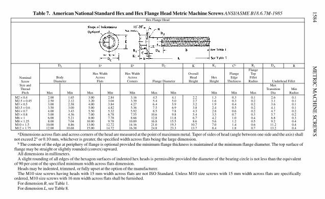
1583Table 6. American National Standard Hex and Hex Flange Head Metric Machine Screws ANSI/ASME B18.6.7M-1985
Hex Head
NominalScrew
Size andThreadPitch
DS Sa
a Dimensions across flats and across corners of the head are measured at the point of maximum metal. Taper of sides of head (angle between one side and the axis) shallnot exceed 2° or 0.10 mm, whichever is greater, the specified width across flats being the large dimension.
Ea K DA R
Body DiameterHex Width
Across Flats
Hex WidthAcross
CornersHead
Height
Underhead Fillet
TransitionDia Radius
Max Min Max Min Min Max Min Max Min
M2 × 0.4 2.00 1.65 3.20 3.02 3.38 1.6 1.3 2.6 0.1
M2.5 × 0.45 2.50 2.12 4.00 3.82 4.28 2.1 1.8 3.1 0.1
M3 × 0.5 3.00 2.58 5.00 4.82 5.40 2.3 2.0 3.6 0.1
M3.5 × 0.6 3.50 3.00 5.50 5.32 5.96 2.6 2.3 4.1 0.1
M4 × 0.7 4.00 3.43 7.00 6.78 7.59 3.0 2.6 4.7 0.2
M5 × 0.8 5.00 4.36 8.00 7.78 8.71 3.8 3.3 5.7 0.2
M6 × 1 6.00 5.21 10.00 9.78 10.95 4.7 4.1 6.8 0.3
M8 × 1.25 8.00 7.04 13.00 12.73 14.26 6.0 5.2 9.2 0.4
M10 × 1.5 10.00 8.86 16.00 15.73 17.62 7.5 6.5 11.2 0.4
M12 × 1.75 12.00 10.68 18.00 17.73 19.86 9.0 7.8 13.2 0.4
M10 × 1.5b
b The contour of the edge at periphery of flange is optional provided the minimum flange thickness is maintained at the minimum flange diameter. The top surface offlange may be straight or slightly rounded (convex) upward.
10.00 8.86 15.00 14.73 16.50 7.5 6.5 11.2 0.4
ME
TR
IC M
AC
HIN
E SC
RE
WS
1584
All dimensions in millimeters.A slight rounding of all edges of the hexagon surfaces of indented hex heads is permissible provided the diameter of the bearing circle is not less than the equivalent
of 90 per cent of the specified minimum width across flats dimension.Heads may be indented, trimmed, or fully upset at the option of the manufacturer.The M10 size screws having heads with 15 mm width across flats are not ISO Standard. Unless M10 size screws with 15 mm width across flats are specifically
ordered, M10 size screws with 16 mm width across flats shall be furnished.For dimension B, see Table 1.For dimension L, see Table 8.
Table 7. American National Standard Hex and Hex Flange Head Metric Machine Screws ANSI/ASME B18.6.7M-1985Hex Flange Head
NominalScrew
Size andThreadPitch
DS Sa Ea DC K K1 Cb R1 DA R
BodyDiameter
Hex WidthAcrossFlats
Hex WidthAcrossCorners Flange Diameter
OverallHead
HeightHex
Height
FlangeEdge
Thickness
FlangeTop
FilletRadius Underhead Fillet
Max Min Max Min Min Max Min Min Min Max
MaxTransition
DiaMin
Radius
M2 × 0.4 2.00 1.65 3.00 2.84 3.16 4.5 4.1 2.2 1.3 0.3 0.1 2.6 0.1M2.5 × 0.45 2.50 2.12 3.20 3.04 3.39 5.4 5.0 2.7 1.6 0.3 0.2 3.1 0.1M3 × 0.5 3.00 2.58 4.00 3.84 4.27 6.4 5.9 3.2 1.9 0.4 0.2 3.6 0.1M3.5 × 0.6 3.50 3.00 5.00 4.82 5.36 7.5 6.9 3.8 2.4 0.5 0.2 4.1 0.1M4 × 0.7 4.00 3.43 5.50 5.32 5.92 8.5 7.8 4.3 2.8 0.6 0.2 4.7 0.2M5 × 0.8 5.00 4.36 7.00 6.78 7.55 10.6 9.8 5.4 3.5 0.7 0.3 5.7 0.2M6 × 1 6.00 5.21 8.00 7.78 8.66 12.8 11.8 6.7 4.2 1.0 0.4 6.8 0.3M8 × 1.25 8.00 7.04 10.00 9.78 10.89 16.8 15.5 8.6 5.6 1.2 0.5 9.2 0.4M10 × 1.5 10.00 8.86 13.00 12.72 14.16 21.0 19.3 10.7 7.0 1.4 0.6 11.2 0.4M12 × 1.75 12.00 10.68 15.00 14.72 16.38 24.8 23.3 13.7 8.4 1.8 0.7 13.2 0.4
a Dimensions across flats and across corners of the head are measured at the point of maximum metal. Taper of sides of head (angle between one side and the axis) shallnot exceed 2° or 0.10 mm, whichever is greater, the specified width across flats being the large dimension.
b The contour of the edge at periphery of flange is optional provided the minimum flange thickness is maintained at the minimum flange diameter. The top surface offlange may be straight or slightly rounded (convex) upward.
MACHINE SCREWS 1585
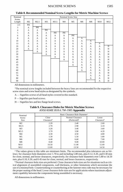
Table 8. Recommended Nominal Screw Lengths for Metric Machine Screws
All dimensions in millimeters.1The nominal screw lengths included between the heavy lines are recommended for the respective
screw sizes and screw head styles as designated by the symbols.
A — Signifies screws of all head styles covered in this standard.
P — Signifies pan head screws.
H — Signifies hex and hex flange head screws.
Table 9. Clearance Holes for Metric Machine Screws ANSI/ASME B18.6.7M-1985 Appendix
All dimensions in millimeters.
NominalScrewLength
Nominal Screw Size
M2 M2.5 M3 M3.5 M4 M5 M6 M8 M10 M12
2.5 PH3 A PH4 A A PH5 A A A PH PH6 A A A A A PH8 A A A A A A A
10 A A A A A A A A13 A A A A A A A A A16 A A A A A A A A A H20 A A A A A A A A A H25 A A A A A A A A H30 A A A A A A A H35 A A A A A A H40 A A A A A H45 A A A A H50 A A A A H55 A A A H60 A A A H65 A A H70 A A H80 A A H90 A H
NominalScrewSize
Basic Clearance Hole Diametera
a The values given in this table are minimum limits. The recommended plus tolerances are as fol-lows: for clearance hole diameters over 1.70 to and including 5.80 mm, plus 0.12, 0.20, and 0.30 mmfor close, normal, and loose clearances, respectively; for clearance hole diameters over 5.80 to 14.50mm, plus 0.18, 0.30, and 0.45 mm for close, normal, and loose clearances, respectively.
CloseClearanceb
b Normal clearance hole sizes are preferred. Close clearance hole sizes are for situations such as crit-ical alignment of assembled components, wall thickness, or other limitations which necessitate theuse of a minimal hole. Countersinking or counterboring at the fastener entry side may be necessary forthe proper seating of the head. Loose clearance hole sizes are for applications where maximum adjust-ment capability between the components being assembled is necessary.
Normal Clearance(Preferred)b
LooseClearanceb
M2 2.20 2.40 2.60M2.5 2.70 2.90 3.10M3 3.20 3.40 3.60
M3.5 3.70 3.90 4.20M4 4.30 4.50 4.80M5 5.30 5.50 5.80M6 6.40 6.60 7.00M8 8.40 9.00 10.00
M10 10.50 11.00 12.00M12 13.00 13.50 14.50
1586 MACHINE SCREWS
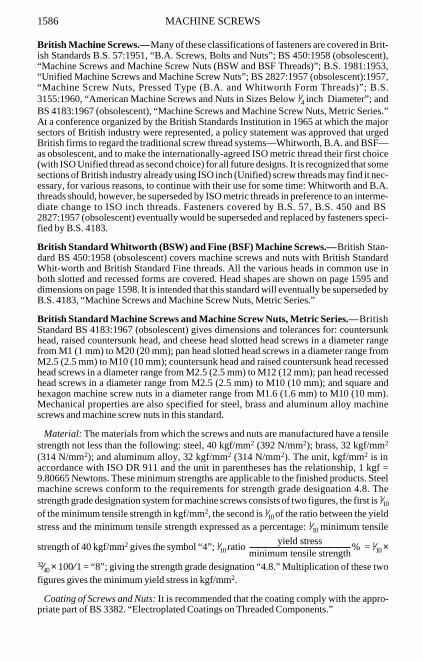
British Machine Screws.—Many of these classifications of fasteners are covered in Brit-ish Standards B.S. 57:1951, “B.A. Screws, Bolts and Nuts”; BS 450:1958 (obsolescent),“Machine Screws and Machine Screw Nuts (BSW and BSF Threads)”; B.S. 1981:1953,“Unified Machine Screws and Machine Screw Nuts”; BS 2827:1957 (obsolescent):1957,“Machine Screw Nuts, Pressed Type (B.A. and Whitworth Form Threads)”; B.S.3155:1960, “American Machine Screws and Nuts in Sizes Below 1⁄4 inch Diameter”; andBS 4183:1967 (obsolescent), “Machine Screws and Machine Screw Nuts, Metric Series.”At a conference organized by the British Standards Institution in 1965 at which the majorsectors of British industry were represented, a policy statement was approved that urgedBritish firms to regard the traditional screw thread systems—Whitworth, B.A. and BSF—as obsolescent, and to make the internationally-agreed ISO metric thread their first choice(with ISO Unified thread as second choice) for all future designs. It is recognized that somesections of British industry already using ISO inch (Unified) screw threads may find it nec-essary, for various reasons, to continue with their use for some time: Whitworth and B.A.threads should, however, be superseded by ISO metric threads in preference to an interme-diate change to ISO inch threads. Fasteners covered by B.S. 57, B.S. 450 and BS2827:1957 (obsolescent) eventually would be superseded and replaced by fasteners speci-fied by B.S. 4183.
British Standard Whitworth (BSW) and Fine (BSF) Machine Screws.—British Stan-dard BS 450:1958 (obsolescent) covers machine screws and nuts with British StandardWhit-worth and British Standard Fine threads. All the various heads in common use inboth slotted and recessed forms are covered. Head shapes are shown on page1595 anddimensions on page1598. It is intended that this standard will eventually be superseded byB.S. 4183, “Machine Screws and Machine Screw Nuts, Metric Series.”
British Standard Machine Screws and Machine Screw Nuts, Metric Series.—BritishStandard BS 4183:1967 (obsolescent) gives dimensions and tolerances for: countersunkhead, raised countersunk head, and cheese head slotted head screws in a diameter rangefrom M1 (1 mm) to M20 (20 mm); pan head slotted head screws in a diameter range fromM2.5 (2.5 mm) to M10 (10 mm); countersunk head and raised countersunk head recessedhead screws in a diameter range from M2.5 (2.5 mm) to M12 (12 mm); pan head recessedhead screws in a diameter range from M2.5 (2.5 mm) to M10 (10 mm); and square andhexagon machine screw nuts in a diameter range from M1.6 (1.6 mm) to M10 (10 mm).Mechanical properties are also specified for steel, brass and aluminum alloy machinescrews and machine screw nuts in this standard.
Material: The materials from which the screws and nuts are manufactured have a tensilestrength not less than the following: steel, 40 kgf/mm2 (392 N/mm2); brass, 32 kgf/mm2
(314 N/mm2); and aluminum alloy, 32 kgf/mm2 (314 N/mm2). The unit, kgf/mm2 is inaccordance with ISO DR 911 and the unit in parentheses has the relationship, 1 kgf =9.80665 Newtons. These minimum strengths are applicable to the finished products. Steelmachine screws conform to the requirements for strength grade designation 4.8. Thestrength grade designation system for machine screws consists of two figures, the first is 1⁄10
of the minimum tensile strength in kgf/mm2, the second is 1⁄10 of the ratio between the yieldstress and the minimum tensile strength expressed as a percentage: 1⁄10 minimum tensile
strength of 40 kgf/mm2 gives the symbol “4”; 1⁄10 ratio = 1⁄10 ×
32⁄40 × 100⁄1 = “8”; giving the strength grade designation “4.8.” Multiplication of these twofigures gives the minimum yield stress in kgf/mm2.
Coating of Screws and Nuts: It is recommended that the coating comply with the appro-priate part of BS 3382. “Electroplated Coatings on Threaded Components.”
yield stressminimum tensile strength-------------------------------------------------------------%

MACHINE SCREWS 1587
Screw Threads: Screw threads are ISO metric coarse pitch series threads in accordancewith B.S. 3643. “ISO Metric Screw Threads,” Part 1, “Thread Data and Standard ThreadSeries.” The external threads used for screws conform to tolerance Class 6g limits(medium fit) as given in B.S. 3643, “ISO Metric Screw Threads,” Part 2, “Limits and Tol-erances for Coarse Pitch Series Threads.” The internal threads used for nuts conform to tol-erance Class 6H limits (medium fit) as given in B.S. 3643: Part 2.
Nominal Lengths of Screws: For countersunk head screws the nominal length is the dis-tance from the upper surface of the head to the extreme end of the shank, including anychamfer, radius, or cone point. For raised countersunk head screws the nominal length isthe distance from the upper surface of the head (excluding the raised portion) to theextreme end of the shank, including any chamfer, radius, or cone point. For pan and cheesehead screws the nominal length is the distance from the underside of the head to theextreme end of the shank, including any chamfer, radius, or cone point. Standard nominallengths and tolerances are given in Table 5.
Lengths of Thread on Screws: The length of thread is the distance from the end of thescrew (including any chamfer, radius, or cone point) to the leading face of a nut withoutcountersink which has been screwed as far as possible onto the screw by hand. The mini-mum thread length is shown in the following table:
All dimensions are in millimeters.
Screws of nominal thread diameter M1, M1.2 and M1.4 and screws of larger diametersthat are too short for the above thread lengths are threaded as far as possible up to the head.
In these screws the length of unthreaded shank under the head does not exceed 11⁄2 pitchesfor lengths up to twice the diameter and 2 pitches for longer lengths, and is defined as thedistance from the leading face of a nut that has been screwed as far as possible onto thescrew by hand to: 1) the junction of the basic major diameter and the countersunk portionof the head on countersunk and raised countersunk heads; and 2) the underside of thehead on other types of heads.
Diameter of Unthreaded Shank on Screws: The diameter of the unthreaded portion ofthe shank on screws is not greater than the basic major diameter of the screw thread and notless than the minimum effective diameter of the screw thread. The diameter of theunthreaded portion of shank is closely associated with the method of manufacture; it willgenerally be nearer the major diameter of the thread for turned screws and nearer the effec-tive diameter for those produced by cold heading.
Radius Under the Head of Screws: The radius under the head of pan and cheese headscrews runs smoothly into the face of the head and shank without any step or discontinuity.A true radius is not essential providing that the curve is smooth and lies wholly within themaximum radius. Any radius under the head of countersunk head screws runs smoothlyinto the conical bearing surface of the head and the shank without any step or discontinuity.The radius values given in Tables 1 and 2 are regarded as the maximum where the shankdiameter is equal to the major diameter of the thread and minimum where the shank diam-eter is approximately equal to the effective diameter of the thread.
NominalThread Dia., da
a Items shown in parentheses are non-preferred.
M1 M1.2 (M1.4) M1.6 M2 (M2.2) M2.5 M3 (M3.5) M4
Thread Lengthb (Min.)
b
b Threaded up to the head.
b b 15 16 17 18 19 20 22
Nominal ThreadDia., da (M4.5) M5 M6 M8 M10 M12 (M14) M16 (M18) M20
Thread Lengthb (Min.) 24 25 28 34 40 46 52 58 64 70

MA
CH
INE
SCR
EW
S1588
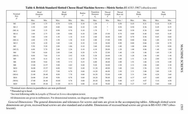
Table 1. British Standard Slotted Countersunk Head Machine Screws— Metric Series BS 4183:1967 (obsolescent)
All dimensions are given in millimeters. For dimensional notation, see diagram on page 1590. Recessed head screws are also standard and are available. For dimen-sions see British Standard.
NominalSizeda
a Nominal sizes shown in parentheses are non-preferred.
Head DiameterD
Head Heightk
Radiusrb
b See Radius Under the Head of Screws description in text.
ThreadLength
b
ThreadRun-out
a
FlushnessTolerancec
c See Dimensions of 90-Degree Countersunk Head Screws description in text.
Slot Widthn
Slot Deptht
Max.(Theor.Sharp)
2d
Min.1.75d
Max.0.5d
Min.0.45d Min. Max.
2pd
d See text following table in Lengths of Thread on Screws description in text.
Max. Max. Min. Max.0.3d
Min.0.2d
M1 2.00 1.75 0.50 0.45 0.1 e
e Threaded up to head.
0.50 .... 0.45 0.31 0.30 0.20
M1.2 2.40 2.10 0.60 0.54 0.1 e 0.50 .... 0.50 0.36 0.36 0.24
(M1.4) 2.80 2.45 0.70 0.63 0.1 e 0.60 .... 0.50 0.36 0.42 0.28
M1.6 3.20 2.80 0.80 0.72 0.1 15.0 0.70 .... 0.60 0.46 0.48 0.32
M2.0 4.00 3.50 1.00 0.90 0.1 16.0 0.80 .... 0.70 0.56 0.60 0.40
(M2.2) 4.40 3.85 1.10 0.99 0.1 17.0 0.90 .... 0.80 0.66 0.66 0.44
M2.5 5.00 4.38 1.25 1.12 0.1 18.0 0.90 0.10 0.80 0.66 0.75 0.50
M3 6.00 5.25 1.50 1.35 0.1 19.0 1.00 0.12 1.00 0.86 0.90 0.60
(M3.5) 7.00 6.10 1.75 1.57 0.2 20.0 1.20 0.13 1.00 0.86 1.05 0.70
M4 8.00 7.00 2.00 1.80 0.2 22.0 1.40 0.15 1.20 1.06 1.20 0.80
(M4.5) 9.00 7.85 2.25 2.03 0.2 24.0 1.50 0.17 1.20 1.06 1.35 0.90
M5 10.00 8.75 2.50 2.25 0.2 25.0 1.60 0.19 1.51 1.26 1.50 1.00
M6 12.00 10.50 3.00 2.70 0.25 28.0 2.00 0.23 1.91 1.66 1.80 1.20
M8 16.00 14.00 4.00 3.60 0.4 34.0 2.50 0.29 2.31 2.06 2.40 1.60
M10 20.00 17.50 5.00 4.50 0.4 40.0 3.00 0.37 2.81 2.56 3.00 2.00
M12 24.00 21.00 6.00 5.40 0.6 46.0 3.50 0.44 3.31 3.06 3.60 2.40
(M14) 28.00 24.50 7.00 6.30 0.6 52.0 4.00 0.52 3.31 3.06 4.20 2.80
M16 32.00 28.00 8.00 7.20 0.6 58.0 4.00 0.60 4.37 4.07 4.80 3.20
(M18) 36.00 31.50 9.00 8.10 0.6 64.0 5.00 0.67 4.37 4.07 5.40 3.60
M20 40.00 35.00 10.00 9.00 0.8 70.0 5.00 0.75 5.37 5.07 6.00 4.00

MA
CH
INE
SCR
EW
S1589
Table 2. British Standard Slotted Raised Countersunk Head Machine Screws— Metric Series BS 4183:1967 (obsolescent)
All dimensions are given in millimeters. For dimensional notation see diagram on page 1590. Recessed head screws are also standard and available. For dimensionssee British Standard.
NominalSizeda
a Nominal sizes shown in parentheses are non-preferred.
Head DiameterD
Head Heightk
RadiusUnderHead
rb
b See Radius Under the Head of Screws description in text.
ThreadLength
b
ThreadRun-outa
Heightof
RaisedPortion
f
HeadRadius
R
Slot Widthn
Slot Deptht
Max.(Theor.Sharp)
2d
Min.1.75d
Max.0.5d
Min.0.45d
Min.Max.2pc
c See text following table in Lengths of Thread on Screws description in text.
Nom.0.25d
Nom. Max. Min. Max.0.5d
Min.0.4d
M1 2.00 1.75 0.50 0.45 0.1 d
d Threaded up to head.
0.50 0.25 2.0 0.45 0.31 0.50 0.40
M1.2 2.40 2.10 0.60 0.54 0.1 d 0.50 0.30 2.5 0.50 0.36 0.60 0.48
(M1.4) 2.80 2.45 0.70 0.63 0.1 d 0.60 0.35 2.5 0.50 0.36 0.70 0.56
M1.6 3.20 2.80 0.80 0.72 0.1 15.0 0.70 0.40 3.0 0.60 0.46 0.80 0.64
M2.0 4.00 3.50 1.00 0.90 0.1 16.0 0.80 0.50 4.0 0.70 0.56 1.00 0.80
(M2.2) 4.40 3.85 1.10 0.99 0.1 17.0 0.90 0.55 4.0 0.80 0.66 1.10 0.88
M2.5 5.00 4.38 1.25 1.12 0.1 18.0 0.90 0.60 5.0 0.80 0.66 1.25 1.00
M3 6.00 5.25 1.50 1.35 0.1 19.0 1.00 0.75 6.0 1.00 0.86 1.50 1.20
(M3.5) 7.00 6.10 1.75 1.57 0.2 20.0 1.20 0.90 6.0 1.00 0.86 1.75 1.40
M4 8.00 7.00 2.00 1.80 0.2 22.0 1.40 1.00 8.0 1.20 1.06 2.00 1.60
(M4.5) 9.00 7.85 2.25 2.03 0.2 24.0 1.50 1.10 8.0 1.20 1.06 2.25 1.80
M5 10.00 8.75 2.50 2.25 0.2 25.0 1.60 1.25 10.0 1.51 1.26 2.50 2.00
M6 12.00 10.50 3.00 2.70 0.25 28.0 2.00 1.50 12.0 1.91 1.66 3.00 2.40
M8 16.00 14.00 4.00 3.60 0.4 34.0 2.50 2.00 16.0 2.31 2.06 4.00 3.20
M10 20.00 17.50 5.00 4.50 0.4 40.0 3.00 2.50 20.0 2.81 2.56 5.00 4.00
M12 24.00 21.00 6.00 5.40 0.6 46.0 3.50 3.00 25.0 3.31 3.06 6.00 4.80
(M14) 28.00 24.50 7.00 6.30 0.6 52.0 4.00 3.50 25.0 3.31 3.06 7.00 5.60
M16 32.00 28.00 8.00 7.20 0.6 58.0 4.00 4.00 32.0 4.37 4.07 8.00 6.40
(M18) 36.00 31.50 9.00 8.10 0.6 64.0 5.00 4.50 32.0 4.37 4.07 9.00 7.20
M20 40.00 35.00 10.00 9.00 0.8 70.0 5.00 5.00 40.0 5.37 5.07 10.00 8.00

1590 MACHINE SCREWS
Ends of Screws: When screws are made with rolled threads, the “lead” formed by thethread rolling operation is normally regarded as providing the necessary chamfer and noother machining is necessary. The ends of screws with cut threads are normally finishedwith a chamfer conforming to the dimension in Fig. 1a through Fig. 1d. At the option of themanufacturer, the ends of screws smaller than M6 (6-mm diameter) may be finished with aradius approximately equal to 11⁄4 times the nominal diameter of the shank. When conepoint ends are required, they should have the dimensions given in Fig. 1a through Fig. 1d.
Dimensions of 90-Degree Countersunk Head Screws: One of the appendices to this Brit-ish Standard states that countersunk head screws should fit into the countersunk hole withas great a degree of flushness as possible. To achieve this condition, it is necessary for thedimensions of both the head of the screw and the countersunk hole to be controlled withinprescribed limits. The maximum or design size of the head is controlled by a theoreticaldiameter to a sharp corner and the minimum head angle of 90 degrees. The minimum headsize is controlled by a minimum head diameter, the maximum head angle of 92 degrees anda flushness tolerance (see Fig. 2, page1591). The edge of the head may be flat or rounded,as shown in Fig. 3 on page1591.
Fig. 1a. Rolled Thread End(Approximate Form as Rolled)
Fig. 1b. Chamfer to Extend to SlightlyBelow the Minor Dia.
Fig. 1c. Cut Thread Radiused End(Permissible on Sizes Below M6 Dia.)
Fig. 1d. Cone Pointed End (Permissible on Cut or Rolled Thread Screws, but Regarded as "Special")
British Standard Machine Screws and Machine Screw Nuts—Metric Series
Slotted Countersunk Head Machine Screws
d
NominalLength
d
NominalLength
Cut Thread Chamfered End
90
RadiusApprox.11/4 d
d
NominalLength
90 d
NominalLength
lk
dn
ar
90 +2
l
b
D D
Edge May BeRounded orFlat, But NotSharp Edges
Shank Dia. ≈Effective
Dia.
Shank Dia. ≈Major Dia.
t

MACHINE SCREWS 1591
For dimensions, see Tables 1 through 5.
Slotted Raised Countersunk Head Machine Screws
Slotted Pan Head Machine Screws
Slotted Cheese Head Machine Screws
Machine Screw Nuts, Pressed Type, Square and Hexagon
Fig. 2. Head Configuration Fig. 3. Edge Configuration
British Standard Machine Screws and Machine Screw Nuts—Metric Series
lk
f
dn
ar
90 +2
l
b
D D
Edge May BeRounded orFlat, But NotSharp Edges
Shank Dia. ≈Effective
Dia.
Shank Dia. ≈Major Dia.
t
R
lk
dn
ar
D
Shank Dia. ≈Effective Dia.
Shank Dia. ≈Major Dia.
t
D
da
0 TO 5
Rl
b
lk
dn
a
r
D
Shank Dia. ≈Major Dia.
Shank Dia. ≈Effective Dia.
t
D
da
0 TO 5
Rl
b
� e
d
m
s
Square Nut Hexagon Nut
�s
d
m
e
1592 MACHINE SCREWS
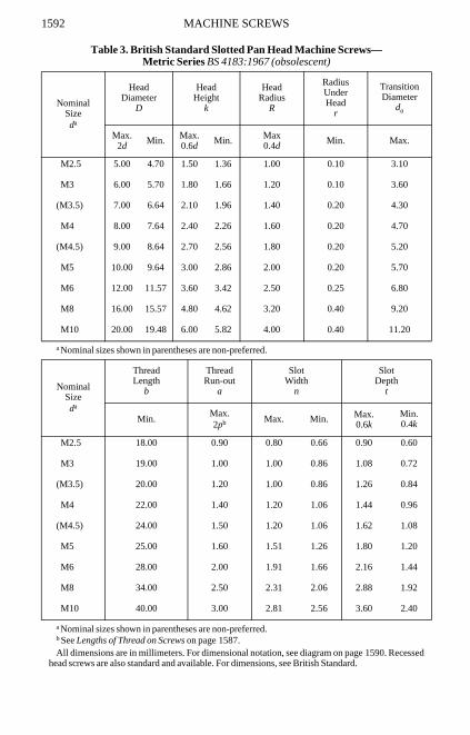
Table 3. British Standard Slotted Pan Head Machine Screws—Metric Series BS 4183:1967 (obsolescent)
All dimensions are in millimeters. For dimensional notation, see diagram on page1590. Recessedhead screws are also standard and available. For dimensions, see British Standard.
NominalSizeda
a Nominal sizes shown in parentheses are non-preferred.
HeadDiameter
D
HeadHeight
k
HeadRadius
R
RadiusUnderHead
r
TransitionDiameter
da
Max.2d Min. Max.
0.6d Min. Max0.4d Min. Max.
M2.5 5.00 4.70 1.50 1.36 1.00 0.10 3.10
M3 6.00 5.70 1.80 1.66 1.20 0.10 3.60
(M3.5) 7.00 6.64 2.10 1.96 1.40 0.20 4.30
M4 8.00 7.64 2.40 2.26 1.60 0.20 4.70
(M4.5) 9.00 8.64 2.70 2.56 1.80 0.20 5.20
M5 10.00 9.64 3.00 2.86 2.00 0.20 5.70
M6 12.00 11.57 3.60 3.42 2.50 0.25 6.80
M8 16.00 15.57 4.80 4.62 3.20 0.40 9.20
M10 20.00 19.48 6.00 5.82 4.00 0.40 11.20
NominalSizeda
a Nominal sizes shown in parentheses are non-preferred.
ThreadLength
b
ThreadRun-out
a
SlotWidth
n
SlotDepth
t
Min.Max.2pb
b See Lengths of Thread on Screws on page1587.
Max. Min. Max.0.6k
Min.0.4k
M2.5 18.00 0.90 0.80 0.66 0.90 0.60
M3 19.00 1.00 1.00 0.86 1.08 0.72
(M3.5) 20.00 1.20 1.00 0.86 1.26 0.84
M4 22.00 1.40 1.20 1.06 1.44 0.96
(M4.5) 24.00 1.50 1.20 1.06 1.62 1.08
M5 25.00 1.60 1.51 1.26 1.80 1.20
M6 28.00 2.00 1.91 1.66 2.16 1.44
M8 34.00 2.50 2.31 2.06 2.88 1.92
M10 40.00 3.00 2.81 2.56 3.60 2.40
MA
CH
INE
SCR
EW
S1593
Table 4. British Standard Slotted Cheese Head Machine Screws— Metric Series BS 4183:1967 (obsolescent)
All dimensions are given in millimeters. For dimensional notation, see diagram on page 1590.
General Dimensions: The general dimensions and tolerances for screws and nuts are given in the accompanying tables. Although slotted screwdimensions are given, recessed head screws are also standard and available. Dimensions of recessed head screws are given in BS 4183:1967 (obso-lescent).
NominalSizeda
a Nominal sizes shown in parentheses are non-preferred.
HeadDiameter
D
HeadHeight
k
Radiusrb
b Threaded up to head.
TransitionDiameter
da
ThreadLength
b
ThreadRun-out
a
SlotWidth
n
SlotDepth
t
Max. Min. Max. Min. Min. Max. Min. Max. c
c See text following table in Lengths of Thread on Screws description in text.
Max. Min. Max. Min.
M1 2.00 1.75 0.70 0.56 0.10 1.30 b 0.50 0.45 0.31 0.44 0.30
M1.2 2.30 2.05 0.80 0.66 0.10 1.50 b 0.50 0.50 0.36 0.49 0.35
(M1.4) 2.60 2.35 0.90 0.76 0.10 1.70 b 0.60 0.50 0.36 0.60 0.40
M1.6 3.00 2.75 1.00 0.86 0.10 2.00 15.00 0.70 0.60 0.46 0.65 0.45
M2 3.80 3.50 1.30 1.16 0.10 2.60 16.00 0.80 0.70 0.56 0.85 0.60
(M2.2) 4.00 3.70 1.50 1.36 0.10 2.80 17.00 0.90 0.80 0.66 1.00 0.70
M2.5 4.50 4.20 1.60 1.46 0.10 3.10 18.00 0.90 0.80 0.66 1.00 0.70
M3 5.50 5.20 2.00 1.86 0.10 3.60 19.00 1.00 1.00 0.86 1.30 0.90
(M3.5) 6.00 5.70 2.40 2.26 0.10 4.10 20.00 1.20 1.00 0.86 1.40 1.00
M4 7.00 6.64 2.60 2.46 0.20 4.70 22.00 1.40 1.20 1.06 1.60 1.20
(M4.5) 8.00 7.64 3.10 2.92 0.20 5.20 24.00 1.50 1.20 1.06 1.80 1.40
M5 8.50 8.14 3.30 3.12 0.20 5.70 25.00 1.60 1.51 1.26 2.00 1.50
M6 10.00 9.64 3.90 3.72 0.25 6.80 28.00 2.00 1.91 1.66 2.30 1.80
M8 13.00 12.57 5.00 4.82 0.40 9.20 34.00 2.50 2.31 2.06 2.80 2.30
M10 16.00 15.57 6.00 5.82 0.40 11.20 40.00 3.00 2.81 2.56 3.20 2.70
M12 18.00 17.57 7.00 6.78 0.60 14.20 46.00 3.50 3.31 3.06 3.80 3.20
(M14) 21.00 20.48 8.00 7.78 0.60 16.20 52.00 4.00 3.31 3.06 4.20 3.60
M16 24.00 23.48 9.00 8.78 0.60 18.20 58.00 4.00 4.37 4.07 4.60 4.00
(M18) 27.00 26.48 10.00 9.78 0.60 20.20 64.00 5.00 4.37 4.07 5.10 4.50
M20 30.00 29.48 11.00 10.73 0.80 22.40 70.00 5.00 5.27 5.07 5.60 5.00
MA
CH
INE
SCR
EW
S1594
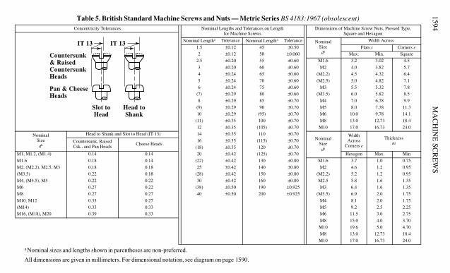
Table 5. British Standard Machine Screws and Nuts — Metric Series BS 4183:1967 (obsolescent)
All dimensions are given in millimeters. For dimensional notation, see diagram on page 1590.
Concentricity Tolerances Nominal Lengths and Tolerances on Lengthfor Machine Screws
Dimensions of Machine Screw Nuts, Pressed Type,Square and Hexagon
Nominal Lengtha
a Nominal sizes and lengths shown in parentheses are non-preferred.
Tolerance Nominal Lengtha Tolerance NominalSizeda
Width Across
1.5 ±0.12 45 ±0.50 Flats s Corners e
2 ±0.12 50 ±0.060 Max. Min. Square
2.5 ±0.20 55 ±0.60 M1.6 3.2 3.02 4.5
3 ±0.20 60 ±0.60 M2 4.0 3.82 5.7
4 ±0.24 65 ±0.60 (M2.2) 4.5 4.32 6.4
5 ±0.24 70 ±0.60 (M2.5) 5.0 4.82 7.1
6 ±0.24 75 ±0.60 M3 5.5 5.32 7.8
(7) ±0.29 80 ±0.60 (M3.5) 6.0 5.82 8.5
8 ±0.29 85 ±0.70 M4 7.0 6.78 9.9
(9) ±0.29 90 ±0.70 M5 8.0 7.78 11.3
10 ±0.29 (95) ±0.70 M6 10.0 9.78 14.1
(11) ±0.35 100 ±0.70 M8 13.0 12.73 18.4
12 ±0.35 (105) ±0.70 M10 17.0 16.73 24.0
NominalSizeda
Head to Shank and Slot to Head (IT 13) 14 ±0.35 110 ±0.70Nominal
Sizeda
WidthAcross
Corners e
ThicknessmCountersunk, Raised
Csk., and Pan Heads Cheese Heads16 ±0.35 (115) ±0.70
(18) ±0.35 120 ±0.70
M1, M1.2, (M1.4) 0.14 0.14 20 ±0.42 (125) ±0.70 Hexagon Max. Min
M1.6 0.18 0.14 (22) ±0.42 130 ±0.80 M1.6 3.7 1.0 0.75
M2, (M2.2), M2.5, M3 0.18 0.18 25 ±0.42 140 ±0.80 M2 4.6 1.2 0.95
(M3.5) 0.22 0.18 (28) ±0.42 150 ±0.80 (M2.2) 5.2 1.2 0.95
M4, (M4.5), M5 0.22 0.22 30 ±0.42 160 ±0.80 M2.5 5.8 1.6 1.35
M6 0.27 0.22 (38) ±0.50 190 ±0.925 M3 6.4 1.6 1.35
M8 0.27 0.27 40 ±0.50 200 ±0.925 (M3.5) 6.9 2.0 1.75
M10, M12 0.33 0.27 M4 8.1 2.0 1.75
(M14) 0.33 0.33 M5 9.2 2.5 2.25
M16, (M18), M20 0.39 0.33 M6 11.5 3.0 2.75
M8 15.0 4.0 3.70
M10 19.6 5.0 4.70
M8 13.0 12.73 18.4
M10 17.0 16.73 24.0
Countersunk& RaisedCountersunkHeads
Pan & CheeseHeads
Slot toHead
IT 13
Head toShank
IT 13
MACHINE SCREWS 1595
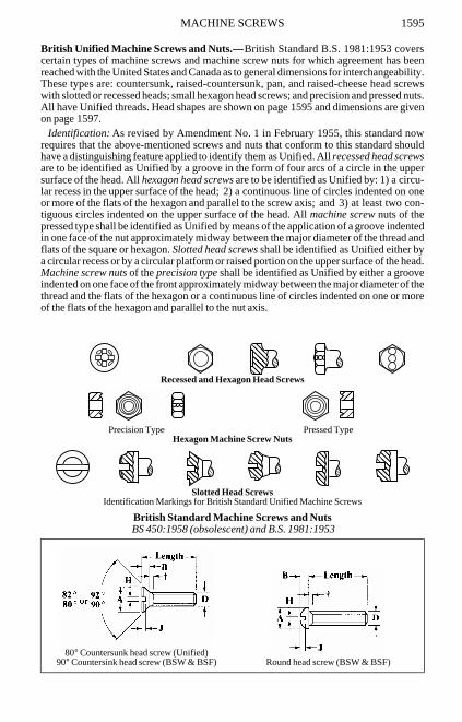
British Unified Machine Screws and Nuts.—British Standard B.S. 1981:1953 coverscertain types of machine screws and machine screw nuts for which agreement has beenreached with the United States and Canada as to general dimensions for interchangeability.These types are: countersunk, raised-countersunk, pan, and raised-cheese head screwswith slotted or recessed heads; small hexagon head screws; and precision and pressed nuts.All have Unified threads. Head shapes are shown on page1595 and dimensions are givenon page1597.
Identification: As revised by Amendment No. 1 in February 1955, this standard nowrequires that the above-mentioned screws and nuts that conform to this standard shouldhave a distinguishing feature applied to identify them as Unified. All recessed head screwsare to be identified as Unified by a groove in the form of four arcs of a circle in the uppersurface of the head. All hexagon head screws are to be identified as Unified by: 1) a circu-lar recess in the upper surface of the head; 2) a continuous line of circles indented on oneor more of the flats of the hexagon and parallel to the screw axis; and 3) at least two con-tiguous circles indented on the upper surface of the head. All machine screw nuts of thepressed type shall be identified as Unified by means of the application of a groove indentedin one face of the nut approximately midway between the major diameter of the thread andflats of the square or hexagon. Slotted head screws shall be identified as Unified either bya circular recess or by a circular platform or raised portion on the upper surface of the head.Machine screw nuts of the precision type shall be identified as Unified by either a grooveindented on one face of the front approximately midway between the major diameter of thethread and the flats of the hexagon or a continuous line of circles indented on one or moreof the flats of the hexagon and parallel to the nut axis.
Recessed and Hexagon Head Screws
Precision Type Pressed TypeHexagon Machine Screw Nuts
Slotted Head ScrewsIdentification Markings for British Standard Unified Machine Screws
British Standard Machine Screws and Nuts BS 450:1958 (obsolescent) and B.S. 1981:1953
80° Countersunk head screw (Unified)90° Countersink head screw (BSW & BSF) Round head screw (BSW & BSF)
����
��
��
��������������������

1596 MACHINE SCREWS
*Countersinks to suit the screws should have a maximum angle of 80° (Unified) or 90° (BSF andBSW) with a negative tolerance.
†Unified countersunk and raised countersunk head screws 2 inches long and under are threadedright up to the head. Other Unified, BSW and BSF machine screws 2 inches long and under have anunthread shank equal to twice the pitch. All Unified, BSW and BSF machine screws longer than 2inches have a minimum thread length of 13⁄4 inches.
80° Raised countersunk head screw (Unified)90° Raised countersunk head screw (BSW & BSF) Mushroom head screw (BSW & BSF)
Pan head screw (Unified, BSW & BSF) Hexagon head screw (Unified)
Cheese head screw (BSW & BSF) Hexagon head screw (Unified) alternate design
Raised cheese head screw (Unified) Hexagon machine screw nut (Unified)
British Standard Machine Screws and Nuts BS 450:1958 (obsolescent) and B.S. 1981:1953

MACHINE SCREWS 1597
All dimensions in inches. See page1595 for a pictorial representation and letter dimensions.
British Standard Unified Machine Screws and Nuts B.S. 1981:1953Nom.Size of Screw
BasicDia. D
Threads per Inch Dia. of Head A Depth of Head B Width of Slot H Depth of Slot JUNC UNF Max. Min. Max. Min. Max. Min.
80° Countersunk Head Screwsa,b
a All dimensions, except J, given for the No. 4 to 3⁄8-inch sizes, incl., also apply to all the 80° RaisedCountersunk Head Screws given in the Standard.
b Also available with recessed heads.
4 0.112 40 … 0.211 0.194 0.067 … 0.039 0.031 0.0256 0.138 32 … 0.260 0.242 0.083 … 0.048 0.039 0.0318 0.164 32 … 0.310 0.291 0.100 … 0.054 0.045 0.037
10 0.190 24c
c Non-preferred.
32 0.359 0.339 0.116 … 0.060 0.050 0.0441⁄4 0.250 20 28 0.473 0.450 0.153 … 0.075 0.064 0.0585⁄16 0.3125 18 24 0.593 0.565 0.191 … 0.084 0.072 0.0733⁄8 0.375 16 24 0.712 0.681 0.230 … 0.094 0.081 0.0867⁄16 0.4375 14 20 0.753 0.719 0.223 … 0.094 0.081 0.0861⁄2 0.500 13 20 0.808 0.770 0.223 … 0.106 0.091 0.0865⁄8 0.625 11 18 1.041 0.996 0.298 … 0.133 0.116 0.1133⁄4 0.750 10 16 1.275 1.223 0.372 … 0.149 0.131 0.141
Pan Head Screwsb
4 0.112 40 … 0.219 0.205 0.068 0.058 0.039 0.031 0.0366 0.138 32 … 0.270 0.256 0.082 0.072 0.048 0.039 0.0448 0.164 32 … 0.322 0.306 0.096 0.085 0.054 0.045 0.051
10 0.190 24c 32 0.373 0.357 0.110 0.099 0.060 0.050 0.0591⁄4 0.250 20 28 0.492 0.473d
d By arrangement may also be 0.468.
0.144 0.130 0.075 0.064 0.0795⁄16 0.3125 18 24 0.615 0.594 0.178 0.162 0.084 0.072 0.1013⁄8 0.375 16 24 0.740 0.716 0.212 0.195 0.094 0.081 0.1227⁄16 0.4375 14 20 0.863 0.838 0.247 0.227 0.094 0.081 0.1331⁄2 0.500 13 20 0.987 0.958 0.281 0.260 0.106 0.091 0.1525⁄8 0.625 11 18 1.125 1.090 0.350 0.325 0.133 0.116 0.1893⁄4 0.750 10 16 1.250 1.209 0.419 0.390 0.149 0.131 0.226
Raised Cheese-Head Screwsb
4 0.112 40 … 0.183 0.166 0.107 0.088 0.039 0.031 0.0426 0.138 32 … 0.226 0.208 0.132 0.111 0.048 0.039 0.0538 0.164 32 … 0.270 0.250 0.156 0.133 0.054 0.045 0.063
10 0.190 24c 32 0.313 0.292 0.180 0.156 0.060 0.050 0.0741⁄4 0.250 20 28 0.414 0.389 0.237 0.207 0.075 0.064 0.0985⁄16 0.3125 18 24 0.518 0.490 0.295 0.262 0.084 0.072 0.1243⁄8 0.375 16 24 0.622 0.590 0.355 0.315 0.094 0.081 0.1497⁄16 0.4375 14 20 0.625 0.589 0.368 0.321 0.094 0.081 0.1531⁄2 0.500 13 20 0.750 0.710 0.412 0.362 0.106 0.091 0.1715⁄8 0.625 11 18 0.875 0.827 0.521 0.461 0.133 0.116 0.2173⁄4 0.750 10 16 1.000 0.945 0.612 0.542 0.149 0.131 0.254
Nom.Size
BasicDia.D
Threadsper Inch
Width Across H'd Depth BNut Thick. E
Wash. FaceDia. FFlats A Corners C
UNC UNF Max. Min. Max. Max. Min. Max. Min.
Hexagon Head Screws
4 0.112 40 … 0.1875 0.1835 0.216 0.060 0.055 0.183 0.1736 0.138 32 … 0.2500 0.2450 0.289 0.080 0.074 0.245 0.2358 0.164 32 … 0.2500 0.2450 0.289 0.110 0.104 0.245 0.235
10 0.190 24c 32 0.3125 0.3075 0.361 0.120 0.113 0.307 0.297Hexagon Machine Screw Nuts—Precision Type
4 0.112 40 … 0.1875 0.1835 0.216 0.098 0.087 … …6 0.138 32 … 0.2500 0.2450 0.269 0.114 0.102 … …8 0.164 32 … 0.3125 0.3075 0.361 0.130 0.117 … …
10 0.190 24c … 0.3125 0.3075 0.361 0.130 0.117 … …Hexagon Machine Screw Nuts—Pressed Type
4 0.112 40 … 0.2500 0.2410 0.289 0.087 0.077 … …6 0.138 32 … 0.3125 0.3020 0.361 0.114 0.102 … …8 0.164 32 … 0.3438 0.3320 0.397 0.130 0.117 … …
10 0.190 24c 32 0.3750 0.3620 0.433 0.130 0.117 … …1⁄4 0.250 20 28 0.4375 0.4230 0.505 0.193 0.178 … …5⁄16 0.3125 18 24 0.5625 0.5450 0.649 0.225 0.208 … …3⁄8 0.375 16 24 0.6250 0.6070 0.722 0.257 0.239 … …

1598 MACHINE SCREWS
All dimensions in inches.See diagram on page1595 for a pictorial representation of screws and letter dimensions.
British Standard Whitworth (BSW) and Fine (BSF) Machine Screws BS 450:1958 (obsolescent)
Nom. Size of Screw
BasicDia. D
Threads per Inch Dia. of Head A Depth of Head B Width of Slot H Depthof Slot JBSW BSF Max. Min. Max. Min. Max. Min.
90°
Co
unt
ersu
nk H
ea
d S
crew
sa
b
a All dimensions, except J, given for the 1⁄8-through 3⁄8-inch sizes also apply to all the 90° RaisedCountersunk Head Screw dimensions given in the Standard.
b These screws are also available with recessed heads; dimensions of recess are not given here butmay be found in the Standard.
1⁄8 0.1250 40 … 0.219 0.201 0.056 … 0.039 0.032 0.0273⁄16 0.1875 24 32c
c Non-preferred size; avoid use whenever possible.
0.328 0.307 0.084 … 0.050 0.042 0.0417⁄32 0.2188 … 28c 0.383 0.360 0.098 … 0.055 0.046 0.0481⁄4 0.2500 20 26 0.438 0.412 0.113 … 0.061 0.051 0.0555⁄16 0.3125 18 22 0.547 0.518 0.141 … 0.071 0.061 0.0693⁄8 0.3750 16 20 0.656 0.624 0.169 … 0.082 0.072 0.0837⁄16 0.4375 14 18 0.766 0.729 0.197 … 0.093 0.082 0.0971⁄2 0.5000 12 16 0.875 0.835 0.225 … 0.104 0.092 0.1119⁄16 0.5625 12c 16c 0.984 0.941 0.253 … 0.115 0.103 0.1255⁄8 0.6250 11 14 1.094 1.046 0.281 … 0.126 0.113 0.1383⁄4 0.7500 10 12 1.312 1.257 0.338 … 0.148 0.134 0.166
Ro
und
He
ad
Scr
ews
b
1⁄8 0.1250 40 … 0.219 0.206 0.087 0.082 0.039 0.032 0.0483⁄16 0.1875 24 32c 0.328 0.312d
d By arrangement may also be 0.309.
0.131 0.124 0.050 0.042 0.0727⁄32 0.2188 … 28c 0.383 0.365 0.153 0.145 0.055 0.046 0.0841⁄4 0.2500 20 26 0.438 0.417 0.175 0.165 0.061 0.051 0.0965⁄16 0.3125 18 22 0.547 0.524 0.219 0.207 0.071 0.061 0.1203⁄8 0.3750 16 20 0.656 0.629 0.262 0.249 0.082 0.072 0.1447⁄16 0.4375 14 18 0.766 0.735 0.306 0.291 0.093 0.082 0.1681⁄2 0.5000 12 16 0.875 0.840 0.350 0.333 0.104 0.092 0.1929⁄16 0.5625 12c 16c 0.984 0.946 0.394 0.375 0.115 0.103 0.2175⁄8 0.6250 11 14 1.094 1.051 0.437 0.417 0.126 0.113 0.2403⁄4 0.7500 10 12 1.312 1.262 0.525 0.500 0.148 0.134 0.288
Pan
He
ad
Scr
ews
b
1⁄8 0.1250 40 … 0.245 0.231 0.075 0.065 0.039 0.032 0.0403⁄16 0.1875 24 32c 0.373 0.375 0.110 0.099 0.050 0.042 0.0617⁄32 0.2188 … 28c 0.425 0.407 0.125 0.112 0.055 0.046 0.0691⁄4 0.2500 20 26 0.492 0.473e
e By arrangement may also be 0.468.
0.144 0.130 0.061 0.051 0.0785⁄16 0.3125 18 22 0.615 0.594 0.178 0.162 0.071 0.061 0.0953⁄8 0.3750 16 20 0.740 0.716 0.212 0.195 0.082 0.072 0.1127⁄16 0.4375 14 18 0.863 0.838 0.247 0.227 0.093 0.082 0.1291⁄2 0.5000 12 16 0.987 0.958 0.281 0.260 0.104 0.092 0.1459⁄16 0.5625 12c 16c 1.031 0.999 0.315 0.293 0.115 0.103 0.1625⁄8 0.6250 11 14 1.125 1.090 0.350 0.325 0.126 0.113 0.1793⁄4 0.7500 10 12 1.250 1.209 0.419 0.390 0.148 0.134 0.213
Che
ese
He
ad
Scr
ews
b
1⁄8 0.1250 40 … 0.188 0.180 0.087 0.082 0.039 0.032 0.0393⁄16 0.1875 24 32c 0.281 0.270 0.131 0.124 0.050 0.042 0.0597⁄32 0.2188 … 28c 0.328 0.315 0.153 0.145 0.055 0.046 0.0691⁄4 0.2500 20 26 0.375 0.360 0.175 0.165 0.061 0.051 0.0795⁄16 0.3125 18 22 0.469 0.450 0.219 0.207 0.071 0.061 0.0983⁄8 0.3750 16 20 0.562 0.540 0.262 0.249 0.082 0.072 0.1187⁄16 0.4375 14 18 0.656 0.630 0.306 0.291 0.093 0.082 0.1381⁄2 0.5000 12 16 0.750 0.720 0.350 0.333 0.104 0.092 0.1579⁄16 0.5625 12c 16c 0.844 0.810 0.394 0.375 0.115 0.103 0.1775⁄8 0.6250 11 14 0.938 0.900 0.437 0.417 0.126 0.113 0.1973⁄4 0.7500 10 12 1.125 1.080 0.525 0.500 0.148 0.134 0.236
Mu
shro
omH
ea
d S
crew
sb 1⁄8 0.1250 40 … 0.289 0.272 0.078 0.066 0.043 0.035 0.0403⁄16 0.1875 24 32c 0.448 0.425 0.118 0.103 0.060 0.050 0.0611⁄4 0.2500 20 26 0.573 0.546 0.150 0.133 0.075 0.064 0.0795⁄16 0.3125 18 22 0.698 0.666 0.183 0.162 0.084 0.072 0.0963⁄8 0.3750 16 20 0.823 0.787 0.215 0.191 0.094 0.081 0.112

![ME 312 Mechanical Machine Design [Screws, Bolts, Nuts]](https://static.fdocuments.us/doc/165x107/58abead91a28ab504e8b545f/me-312-mechanical-machine-design-screws-bolts-nuts.jpg)