
Machine for LH 60 M Industrial...
20
Operating Weight: 129,650 – 133,500 lb Engine Output (SAE J1349): 241 HP / 180 kW Engine Output (ISO 9249): 244 HP / 180 kW Max. System Performance (SAE J1349): 288 kW Max. System Performance (ISO 9249): 288 kW LH 60 M litronic ` Machine for Industrial Applications
Transcript of Machine for LH 60 M Industrial...
TB_LH60M_enUS.indd 12 06.03.14 11:11
Operating Weight: 129,650 – 133,500 lbEngine Output (SAE J1349): 241 HP / 180 kWEngine Output (ISO 9249): 244 HP / 180 kWMax. System Performance (SAE J1349): 288 kWMax. System Performance (ISO 9249): 288 kW
LH 60 Mlitronic̀
Machine for Industrial Applications

2 LH 60 M Litronic Machine for Industrial Applications
Technical Data
EngineRating per SAE J1349 �������������� 241 HP (180 kW) at 1,700 rpmRating per ISO 9249 ���������������� 244 HP (180 kW) at 1,700 rpmModel ������������������������������� Liebherr D936 according to stage IIIB / Tier 4iType ��������������������������������� 6 cylinder in-line Bore/Stroke ������������������� 4.8/5.9 in Displacement ����������������� 640 in3
Engine operation ������������������� 4-stroke diesel Common-Rail turbo-charged and after-cooled reduced emissions
Harmful emissions values ���������� in accordance with EPA/CARB-40CFR stage Tier 4 interimEmission control �������������������� Liebherr particle filterCooling ������������������������������ water-cooled with integrated motor oil coolerAir cleaner ��������������������������� dry-type air cleaner with pre-cleaner, primary and
safety elementsFuel tank ���������������������������� 198 galEngine idling ������������������������ sensor controlledElectrical system Voltage ������������������������ 24 V Batteries ����������������������� 2 x 170 Ah/12 V Alternator ���������������������� three phase current 28 V/100 A
Hydraulic SystemHydraulic pump for attachment and travel drive ���������������� two Liebherr variable flow, swashplate pumps (double
construction) Max. flow ���������������������� 2 x 77 gpm Max. pressure ����������������� 5,076 psiHydraulic pumpregulation and control �������������� electro-hydraulic with electronic engine speed sensing
regulation, pressure compensation, flow compensation, automatic oil flow optimizer
Hydraulic pump for swing drive ���������������� reversible, variable flow, swashplate pump, closed-loop
circuit Max. flow ���������������������� 50 gpm Max. pressure ����������������� 5,511 psiHydraulic tank ���������������������� 77 galHydraulic system ������������������� 235 galHydraulic oil filter ������������������� 2 main return filters with integrated partial micro
filtration (5 μm)Hydraulic oil cooler ����������������� compact cooling system consisting cooling unit for
water, hydraulic oil and charge air with stepless thermostatically controlled fan
MODE selection �������������������� adjustment of engine and hydraulic performance via a mode pre-selector to match application, e.g. for espe-cially economical and environmentally friendly opera-tion or for maximum material handling and heavy-duty jobs
S (Sensitive) ������������������� for precision work and lifting through very sensitive movements
E (ECO) ������������������������ for especially economical and environmentally friendly operation
P (Power) ���������������������� for maximum digging power and heavy duty jobsTool Control (Option) ��������������� ten preadjustable pump flows and pressures for add on
tools
Hydraulic ControlsPower distribution ������������������ via control valves in single block with integrated safety
valvesServo circuit Attachment and swing �������� with hydraulic pilot control and proportional joystick
levers Travel �������������������������� electroproportional via foot pedalAdditional functions ���������������� via switch or electroproportional foot pedalsOption ������������������������������� proportional control, proportionally acting transmitters
on the joysticks for additional hydraulic functions
Swing DriveDrive ��������������������������������� Liebherr swashplate motor in a closed system with
integrated brake valveTransmission ����������������������� Liebherr planetary reduction gearSwing ring �������������������������� Liebherr, sealed single race ball bearing swing ring,
internal teethSwing speed ������������������������ 0 – 7.6 rpm steplessSwing torque ����������������������� 88,500 lbf ftBrake �������������������������������� holding brake (spring applied – pressure released)Option ������������������������������� pedal controlled positioning swing brake
UppercarriageType ��������������������������������� slewing platform made from high-strength steel plate,
designed for the toughest requirements
Operator’s CabCab ���������������������������������� safety cab structure with individual windscreens or
featuring a slide-in subpart under the ceiling, work headlights integrated in the ceiling, a door with a side window (can be opened on both sides), large stowing and depositing possibilities, shock-absorbing suspen-sion, sounddamping insulating, tinted laminated safety glass, separate shades for the sunroof window and windscreen
Operator’s seat Standard ������������ air cushioned operator’s seat with headrest, lap belt, seat heater, manual weight adjustment, adjustable seat cushion inclination and length and mechanical lumbar vertebrae support
Operator’s seat Comfort (Option) ���� in addition to operator’s seat standard: lockable hori-zontal suspension, automatic weight adjustment, adjust-able suspension stiffness, pneumatic lumbar vertebrae support and passive seat climatisation with active coal
Operator’s seat Premium (Option) ��� in addition to operator’s seat comfort: active elec tronic weight adjustment (automatic readjustment), pneumatic low frequency suspension and active seat climatisation with active coal and ventilator
Control system ���������������������� joysticks with arm consoles and swivel seatOperation and displays ������������ large high-resolution operating unit, selfexplanatory,
colour display with touchscreen, video-compatible, numerous setting, control and monitoring options, e.g. air conditioning control, fuel consumption, machine and tool parameters
Air-conditioning ��������������������� automatic air-conditioning, recirculated air function, fast de-icing and demisting at the press of a button, air vents can be operated via a menu; recirculated air and fresh air filters can be easily replaced and are accessible from the outside; heating-cooling unit, designed for extreme out-side temperatures, sensors for solar radiation, inside and outside temperatures
Noise emissionISO 6396 ���������������������������� LpA (inside cab) = 71 dB(A)2000/14/EC ������������������������� LWA (surround noise) = 105 dB(A)
AttachmentType ��������������������������������� high-strength steel plates at highlystressed points
for the toughest requirements. Complex and stable mountings of attachment and cylinders.
Hydraulic cylinders ����������������� Liebherr cylinders with special seal system. Shock absorption
Energy recovering cylinder ��������� Liebherr gas cylinder with special sealing and control system
Bearings ����������������������������� sealed, low maintenance
UndercarriageType ��������������������������������� torsion-resistant box design made from high-strength
steel plate, designed for the toughest requirementsDrive ��������������������������������� variable flow swashplate motor with automatic brake
valveTravel speed ������������������������ 0 – 6.8 mph steplessDriving operation ������������������� automotive driving using accelerator pedal, cruise
control function: storage of variable accelerator pedal positions
Axles �������������������������������� 154,320 lb drive axles; manual or automatic hydraulically controlled front axle oscillation lock
Service brake ����������������������� disc brake, two circuit travel brake system with accu-mulator
Holding brake ����������������������� wet, maintenance-free multi disc brakesStabilization ������������������������� 4 point outriggers
Complete MachineLubrication �������������������������� central lubrication system for uppercarriage and attach-
ment, automatically

LH 60 M Litronic Machine for Industrial Applications 3
Dimensions11'9"
5'7"
24'5"
5'4" 5'4"
22'7"21'9"11'2"
11'8"
6'4"
14'6"
13'10"
10'6"
17.9"
11'6"
13.5"
12'3"18'10"
US_H0592
Choice of Cab Elevation
B1C1
B2C2
E
D1D2
B
D
H0593
C
Cab Elevation LHC (Hydraulic Elevation)
Cab Elevation LFC (Rigid Elevation)
Tires 20.5 x 25
Increase Type LFC 80 LFC 120 LFC 150
Height 2’7” 3’11” 4’11”
B 13’7” 14’10” 15’10”C 15’4” 16’ 8” 17’ 7”D 2’8” 2’ 8” 2’ 8”
A rigid cab elevation has a fixed eye level height. For a lower transport height, the shell of the cab can be removed and replaced by a transport device. The dimension C is in this machine design for all rigid cab elevations 13’8”.
Increase Type LHC 255 LHC 340-35B1 10’11” 12’ 1”B2 19’ 3” 23’ 3”C1 12’ 8” 13’10”C2 21’ 1” 25’ 1”D1 4’ 6” 8’ 2”D2 4’11” 8’ 2”E 12’ 6” 13’ 9”
The hydraulically adjustable cab allows the driver, that he can choose his field of view freely and at any time within the stroke.

4 LH 60 M Litronic Machine for Industrial Applications
Attachment GK15 (Kinematic 2A)
30
55
60
65
70
50
45
40
35
25
20
15
10
5
0
-5
-10
-15
8
10
12
14
16
18
20
22 H0612
3540455055 30 25 20 15 10 5 0
12141618 10 8 6 4 2 0
6
4
2
0
-2
-4
-6mft m
ft
26'11"
44'7"
13'10"
US_H0614
12'
Dimensions
Operating WeightThe operating weight includes basic machine with 4 point outriggers, hydr. cab elevation, 4 solid tires, industrial-type straight mono boom 31’2” and industrial-type stick with tipping kinematics 19’8”.
with sorting grab SG 40/1.70 yd3 tines 131,600 lb
Industrial Stick 19’8” ft
Undercarriage
10 ft 15 ft 20 ft 25 ft 30 ft 35 ft 40 ft 45 ft 50 ft 55 ft 60 ft 65 ft
ft in 55 Stabilizers raised 34,7* 34,7* 28,1* 28,1* 27,1* 27,1*
20’ 7”4 pt. outriggers down 34,7* 34,7* 28,1* 28,1* 27,1* 27,1*
50 Stabilizers raised 33,0* 33,0* 25,8 28,6* 19,1 21,7*29’ 4”
4 pt. outriggers down 33,0* 33,0* 28,6* 28,6* 21,7* 21,7*
45 Stabilizers raised 33,7* 33,7* 26,7 28,6* 19,2 24,0 13,9 17,7 13,7 17,535’ 2”
4 pt. outriggers down 33,7* 33,7* 28,6* 28,6* 25,2* 25,2* 19,8* 19,8* 19,3* 19,3*
40 Stabilizers raised 33,4* 33,4* 26,8 28,4* 19,4 24,2 14,4 18,2 10,9 14,139’ 7”
4 pt. outriggers down 33,4* 33,4* 28,4* 28,4* 24,9* 24,9* 22,3* 22,3* 17,9* 17,9*
35 Stabilizers raised 33,9* 33,9* 26,5 28,6* 19,3 24,0 14,4 18,2 10,9 14,1 9,1 12,043’
4 pt. outriggers down 33,9* 33,9* 28,6* 28,6* 24,9* 24,9* 22,2* 22,2* 20,1* 20,1* 17,1* 17,1*
30 Stabilizers raised 35,1* 35,1* 25,6 29,4* 18,7 23,5 14,1 17,9 10,8 14,0 8,3 10,9 8,0 10,645’ 7”
4 pt. outriggers down 35,1* 35,1* 29,4* 29,4* 25,4* 25,4* 22,4* 22,4* 20,1* 20,1* 18,2* 18,2* 16,6* 16,6*
25 Stabilizers raised 37,7* 37,7* 34,9 37,2* 24,3 30,6 17,9 22,6 13,6 17,4 10,5 13,7 8,2 10,9 7,2 9,747’ 6”
4 pt. outriggers down 37,7* 37,7* 37,2* 37,2* 30,6* 30,6* 26,1* 26,1* 22,9* 22,9* 20,3* 20,3* 18,1* 18,1* 16,4* 16,4*
20 Stabilizers raised 80,1* 80,1* 50,1 52,9* 31,9 39,8* 22,5 28,7 16,8 21,5 12,9 16,7 10,1 13,2 8,0 10,6 6,6 9,048’10”
4 pt. outriggers down 80,1* 80,1* 52,9* 52,9* 39,8* 39,8* 32,1* 32,1* 27,0* 27,0* 23,4* 23,4* 20,5* 20,5* 18,1* 18,1* 16,2* 16,2*
15 Stabilizers raised 24,2* 24,2* 28,5 37,3 20,6 26,7 15,6 20,3 12,2 15,9 9,6 12,7 7,7 10,4 6,3 8,649’ 7”
4 pt. outriggers down 24,2* 24,2* 42,6* 42,6* 33,7* 33,7* 27,9* 27,9* 23,8* 23,8* 20,7* 20,7* 18,0* 18,0* 15,3* 15,3*
10 Stabilizers raised 5,1* 5,1* 25,4 34,0 18,8 24,8 14,5 19,1 11,4 15,1 9,2 12,3 7,4 10,1 6,1 8,449’11”
4 pt. outriggers down 5,1* 5,1* 44,4* 44,4* 34,7* 34,7* 28,5* 28,5* 24,1* 24,1* 20,7* 20,7* 17,7* 17,7* 14,3* 14,3*
5 Stabilizers raised 5,1* 5,1* 23,4 26,9* 17,4 23,3 13,6 18,1 10,8 14,5 8,8 11,8 7,2 9,8 6,1 8,449’ 8”
4 pt. outriggers down 5,1* 5,1* 26,9* 26,9* 34,8* 34,8* 28,5* 28,5* 23,9* 23,9* 20,2* 20,2* 17,0* 17,0* 13,1* 13,1*
0 Stabilizers raised 8,8* 8,8* 22,3 24,6* 16,5 22,4 12,9 17,4 10,3 14,0 8,4 11,5 7,0 9,7 6,2 8,648’ 7”
4 pt. outriggers down 8,8* 8,8* 24,6* 24,6* 33,3* 33,3* 27,5* 27,5* 22,9* 22,9* 19,2* 19,2* 15,5* 15,5* 12,0* 12,0*
– 5 Stabilizers raised 22,0 26,9* 16,1 22,0 12,5 17,0 10,1 13,7 8,3 11,3 7,1 9,844’ 6”
4 pt. outriggers down 26,9* 26,9* 30,0* 30,0* 25,1* 25,1* 20,9* 20,9* 17,1* 17,1* 13,3* 13,3*
– 10 Stabilizers raised4 pt. outriggers down
– 15 Stabilizers raised4 pt. outriggers down
Height Can be slewed through 360° In longitudinal position of undercarriage Max. reach * Limited by hydr. capacity
The lift capacities on the stick end without attachment are stated in lb x 1,000 and are valid on a firm, level supporting surface with blocked oscillating axle. These capacities can be slewed through 360° with the undercarriage in the transverse position. Capacities in the longitudinal position of the undercarriage (+/– 15°) are specified over the steering axle with the stabilizers raised and over the rigid axle with the stabilizers down. Indicated loads comply with the ISO 10567 standard and do not exceed 75 % of tipping or 87 % of hydraulic capacity. The lift capacity values indicated are attained at the corresponding operating temperature. This operating temperature is ensured by continuous movement of the boom. Weights of fitted working tools (grabs, load hooks, etc.) and load accommodation equipment are to be deducted from the lift capacity values. The lift capacity of the unit is limited by its stability, the lifting capability of the hydraulic elements, or the maximum permissible lifting capacity of the load hook.

LH 60 M Litronic Machine for Industrial Applications 5
Attachment AG16 (Kinematic 2D)
30
55
50
45
40
35
25
20
15
10
5
0
-5
-10
-15
-20
-25
-30
8
10
12
14
16
18 H0611
3540455055 30 25 20 15 10 5 0
12141618 10 8 6 4 2 0
6
4
2
0
-2
-4
-6
-8
-10mft m
ft
22'10"
44'2"
13'10"
US_H0612
13'1"
Dimensions
Operating WeightThe operating weight includes basic machine with 4 point outriggers, hydr. cab elevation, 4 solid tires, industrial-type angled mono boom 31’2” and industrial-type straight stick 23’11”.
with clamshell model GM 20B/2.62 yd3
shells for loose material
130,200 lb
Industrial Stick 23’11” ft
Undercarriage
10 ft 15 ft 20 ft 25 ft 30 ft 35 ft 40 ft 45 ft 50 ft 55 ft 60 ft 65 ft
ft in 55 Stabilizers raised 19,8* 19,8* 18,4* 18,4*
26’ 2”4 pt. outriggers down 19,8* 19,8* 18,4* 18,4*
50 Stabilizers raised 20,3* 20,3* 16,2* 16,2*33’ 5”
4 pt. outriggers down 20,3* 20,3* 16,2* 16,2*
45 Stabilizers raised 21,2* 21,2* 16,9 19,6* 13,7 15,1*38’ 8”
4 pt. outriggers down 21,2* 21,2* 19,6* 19,6* 15,1* 15,1*
40 Stabilizers raised 21,0* 21,0* 17,1 19,3* 13,2 16,4 11,3 14,342’10”
4 pt. outriggers down 21,0* 21,0* 19,3* 19,3* 18,1* 18,1* 14,5* 14,5*
35 Stabilizers raised 21,2* 21,2* 17,0 19,4* 13,2 16,4 10,2 13,0 9,8 12,445’11”
4 pt. outriggers down 21,2* 21,2* 19,4* 19,4* 18,0* 18,0* 15,8* 15,8* 14,1* 14,1*
30 Stabilizers raised 21,8* 21,8* 16,7 19,8* 13,0 16,2 10,2 12,9 8,6 11,148’ 4”
4 pt. outriggers down 21,8* 21,8* 19,8* 19,8* 18,2* 18,2* 17,0* 17,0* 14,0* 14,0*
25 Stabilizers raised 25,7* 25,7* 20,9 22,7* 16,0 19,9 12,6 15,8 10,0 12,7 7,9 10,3 7,8 10,250’ 2”
4 pt. outriggers down 25,7* 25,7* 22,7* 22,7* 20,4* 20,4* 18,6* 18,6* 17,2* 17,2* 14,4* 14,4* 14,0* 14,0*
20 Stabilizers raised 33,0* 33,0* 26,3 27,6* 19,7 23,9* 15,3 19,1 12,1 15,3 9,7 12,4 7,8 10,1 7,3 9,551’ 5”
4 pt. outriggers down 33,0* 33,0* 27,6* 27,6* 23,9* 23,9* 21,2* 21,2* 19,1* 19,1* 17,5* 17,5* 16,2* 16,2* 14,2* 14,2*
15 Stabilizers raised 73,9* 73,9* 48,5* 48,5* 33,7 36,6* 24,2 29,7* 18,3 23,1 14,3 18,1 11,5 14,6 9,3 12,0 7,5 9,9 6,9 9,152’ 2”
4 pt. outriggers down 73,9* 73,9* 48,5* 48,5* 36,6* 36,6* 29,7* 29,7* 25,3* 25,3* 22,1* 22,1* 19,7* 19,7* 17,9* 17,9* 16,4* 16,4* 14,6* 14,6*
10 Stabilizers raised 41,3* 41,3* 29,8 38,7 21,9 28,1 16,9 21,6 13,4 17,2 10,8 14,0 8,8 11,5 7,3 9,6 6,6 8,852’ 5”
4 pt. outriggers down 41,3* 41,3* 40,2* 40,2* 31,9* 31,9* 26,6* 26,6* 23,0* 23,0* 20,3* 20,3* 18,2* 18,2* 16,5* 16,5* 15,1* 15,1*
5 Stabilizers raised 6,2* 6,2* 20,1* 20,1* 26,6 35,2 19,9 26,0 15,6 20,2 12,5 16,2 10,2 13,3 8,4 11,1 7,0 9,3 6,5 8,752’ 2”
4 pt. outriggers down 6,2* 6,2* 20,1* 20,1* 42,9* 42,9* 33,7* 33,7* 27,8* 27,8* 23,8* 23,8* 20,8* 20,8* 18,5* 18,5* 16,4 16,4* 15,3 15,4*
0 Stabilizers raised 9,0* 9,0* 18,0* 18,0* 24,4 32,8 18,4 24,3 14,5 19,1 11,7 15,4 9,7 12,8 8,1 10,7 6,8 9,1 6,5 8,751’ 6”
4 pt. outriggers down 9,0* 9,0* 18,0* 18,0* 38,7* 38,7* 34,7* 34,7* 28,6* 28,6* 24,2* 24,2* 21,0* 21,0* 18,4* 18,4* 16,0* 16,0* 15,2* 15,2*
– 5 Stabilizers raised 12,4* 12,4* 19,4* 19,4* 23,1 31,5 17,4 23,3 13,7 18,3 11,2 14,9 9,3 12,4 7,8 10,5 6,7 9,0 6,6 8,950’ 4”
4 pt. outriggers down 12,4* 12,4* 19,4* 19,4* 34,0* 34,0* 34,8* 34,8* 28,6* 28,6* 24,2* 24,2* 20,8* 20,8* 18,0* 18,0* 15,1* 15,1* 14,9* 14,9*
– 10 Stabilizers raised 21,7* 21,7* 22,6 30,9 16,8 22,7 13,2 17,8 10,8 14,5 9,0 12,1 7,7 10,3 6,9 9,448’ 7”
4 pt. outriggers down 21,7* 21,7* 33,8* 33,8* 33,5* 33,5* 27,8* 27,8* 23,5* 23,5* 20,0* 20,0* 16,8* 16,8* 14,3* 14,3*
– 15 Stabilizers raised 22,6 30,9 16,6 22,5 13,1 17,6 10,7 14,3 9,0 12,0 8,0 10,843’ 8”
4 pt. outriggers down 35,6* 35,6* 30,7* 30,7* 25,7* 25,7* 21,6* 21,6* 18,1* 18,1* 15,4* 15,4*
Height Can be slewed through 360° In longitudinal position of undercarriage Max. reach * Limited by hydr. capacity
The lift capacities on the stick end without attachment are stated in lb x 1,000 and are valid on a firm, level supporting surface with blocked oscillating axle. These capacities can be slewed through 360° with the undercarriage in the transverse position. Capacities in the longitudinal position of the undercarriage (+/– 15°) are specified over the steering axle with the stabilizers raised and over the rigid axle with the stabilizers down. Indicated loads comply with the ISO 10567 standard and do not exceed 75 % of tipping or 87 % of hydraulic capacity. The lift capacity values indicated are attained at the corresponding operating temperature. This operating temperature is ensured by continuous movement of the boom. Weights of fitted working tools (grabs, load hooks, etc.) and load accommodation equipment are to be deducted from the lift capacity values. The lift capacity of the unit is limited by its stability, the lifting capability of the hydraulic elements, or the maximum permissible lifting capacity of the load hook.

6 LH 60 M Litronic Machine for Industrial Applications
Attachment AG16 (Kinematic 2C)
22'6"
44'
13'10"
US_H0604
12'6"
Dimensions
Operating WeightThe operating weight includes basic machine with 4 point outriggers, hydr. cab elevation, 4 solid tires, industrial-type angled mono boom 31’2” and industrial-type straight stick 23’11”.
with clamshell model GM 20B/2.62 yd3
shells for loose material
130,200 lb
Industrial Stick 23’11” ft
Undercarriage
10 ft 15 ft 20 ft 25 ft 30 ft 35 ft 40 ft 45 ft 50 ft 55 ft 60 ft 65 ft
ft in 50 Stabilizers raised 16,2* 16,2*
33’ 5”4 pt. outriggers down 16,2* 16,2*
45 Stabilizers raised 16,9 17,8* 13,7 15,1*38’ 8”
4 pt. outriggers down 17,8* 17,8* 15,1* 15,1*
40 Stabilizers raised 17,1 17,5* 13,2 16,4 11,4 14,342’10”
4 pt. outriggers down 17,5* 17,5* 16,7* 16,7* 14,5* 14,5*
35 Stabilizers raised 17,0 17,6* 13,2 16,4 10,3 13,0 9,8 12,445’11”
4 pt. outriggers down 17,6* 17,6* 16,6* 16,6* 15,8* 15,8* 14,1* 14,1*
30 Stabilizers raised 16,7 18,0* 13,0 16,2 10,2 13,0 8,7 11,148’ 4”
4 pt. outriggers down 18,0* 18,0* 16,8* 16,8* 15,9* 15,9* 14,0* 14,0*
25 Stabilizers raised 20,5* 20,5* 16,1 18,7* 12,6 15,8 10,0 12,7 7,9 10,3 7,9 10,250’ 2”
4 pt. outriggers down 20,5* 20,5* 18,7* 18,7* 17,2* 17,2* 16,2* 16,2* 14,4* 14,4* 14,0* 14,0*
20 Stabilizers raised 25,0* 25,0* 19,7 21,8* 15,3 19,1 12,1 15,3 9,7 12,4 7,8 10,1 7,3 9,551’ 5”
4 pt. outriggers down 25,0* 25,0* 21,8* 21,8* 19,6* 19,6* 17,8* 17,8* 16,5* 16,5* 15,5* 15,5* 14,2* 14,2*
15 Stabilizers raised 67,3* 67,3* 44,1* 44,1* 33,5* 33,5* 24,2 27,4* 18,3 23,1 14,4 18,2 11,5 14,6 9,3 12,0 7,5 9,9 6,9 9,152’ 2”
4 pt. outriggers down 67,3* 67,3* 44,1* 44,1* 33,5* 33,5* 27,4* 27,4* 23,4* 23,4* 20,6* 20,6* 18,6* 18,6* 17,0* 17,0* 15,8* 15,8* 14,6* 14,6*
10 Stabilizers raised 41,3* 41,3* 29,8 37,5* 21,9 28,1 16,9 21,6 13,4 17,2 10,8 14,0 8,8 11,5 7,3 9,6 6,6 8,852’ 5”
4 pt. outriggers down 41,3* 41,3* 37,5* 37,5* 29,8* 29,8* 25,0* 25,0* 21,7* 21,7* 19,3* 19,3* 17,5* 17,5* 16,0* 16,0* 15,1* 15,1*
5 Stabilizers raised 6,2* 6,2* 20,1* 20,1* 26,6 35,2 19,9 26,0 15,6 20,2 12,5 16,2 10,2 13,3 8,4 11,1 7,0 9,4 6,5 8,752’ 2”
4 pt. outriggers down 6,2* 6,2* 20,1* 20,1* 40,9* 40,9* 32,0* 32,0* 26,5* 26,5* 22,7* 22,7* 20,0* 20,0* 17,9* 17,9* 16,2* 16,2* 15,3 15,4*
0 Stabilizers raised 9,0* 9,0* 18,0* 18,0* 24,4 32,9 18,4 24,4 14,5 19,1 11,8 15,5 9,7 12,8 8,1 10,7 6,8 9,1 6,5 8,751’ 6”
4 pt. outriggers down 9,0* 9,0* 18,0* 18,0* 38,7* 38,7* 33,6* 33,6* 27,6* 27,6* 23,5* 23,5* 20,5* 20,5* 18,1* 18,1* 16,1* 16,1* 15,4* 15,4*
– 5 Stabilizers raised 12,4* 12,4* 19,4* 19,4* 23,1 31,5 17,4 23,3 13,7 18,3 11,2 14,9 9,3 12,4 7,8 10,5 6,7 9,0 6,6 8,950’ 4”
4 pt. outriggers down 12,4* 12,4* 19,4* 19,4* 34,0* 34,0* 34,3* 34,3* 28,2* 28,2* 23,9* 23,9* 20,6* 20,6* 18,0* 18,0* 15,5* 15,5* 15,3* 15,3*
– 10 Stabilizers raised 15,7* 15,7* 21,7* 21,7* 22,6 30,9 16,8 22,7 13,2 17,8 10,8 14,5 9,0 12,1 7,7 10,3 6,9 9,448’ 7”
4 pt. outriggers down 15,7* 15,7* 21,7* 21,7* 33,8* 33,8* 33,8* 33,8* 27,9* 27,9* 23,6* 23,6* 20,2* 20,2* 17,3* 17,3* 15,0* 15,0*
– 15 Stabilizers raised 24,4* 24,4* 22,5 30,9 16,6 22,5 13,1 17,6 10,7 14,3 9,0 12,0 7,7 10,4 7,5 10,146’ 2”
4 pt. outriggers down 24,4* 24,4* 35,6* 35,6* 31,9* 31,9* 26,6* 26,6* 22,4* 22,4* 18,9* 18,9* 15,4* 15,4* 14,4* 14,4*
– 20 Stabilizers raised 22,9 31,3 16,8 22,7 13,2 17,7 10,8 14,4 9,1 12,2 8,4 11,243’
4 pt. outriggers down 33,5* 33,5* 28,2* 28,2* 23,7* 23,7* 19,8* 19,8* 16,0* 16,0* 13,4* 13,4*
Height Can be slewed through 360° In longitudinal position of undercarriage Max. reach * Limited by hydr. capacity
The lift capacities on the stick end without attachment are stated in lb x 1,000 and are valid on a firm, level supporting surface with blocked oscillating axle. These capacities can be slewed through 360° with the undercarriage in the transverse position. Capacities in the longitudinal position of the undercarriage (+/– 15°) are specified over the steering axle with the stabilizers raised and over the rigid axle with the stabilizers down. Indicated loads comply with the ISO 10567 standard and do not exceed 75 % of tipping or 87 % of hydraulic capacity. The lift capacity values indicated are attained at the corresponding operating temperature. This operating temperature is ensured by continuous movement of the boom. Weights of fitted working tools (grabs, load hooks, etc.) and load accommodation equipment are to be deducted from the lift capacity values. The lift capacity of the unit is limited by its stability, the lifting capability of the hydraulic elements, or the maximum permissible lifting capacity of the load hook.
30
55
50
45
40
35
25
20
15
10
5
0
-5
-10
-15
-20
-25
-30
-35
8
10
12
14
16
18 US_H0603
3540455055 30 25 20 15 10 5 0
12141618 10 8 6 4 2 0
6
4
2
0
-2
-4
-6
-8
-10
-12mft m
ft
LH 60 M Litronic Machine for Industrial Applications 7
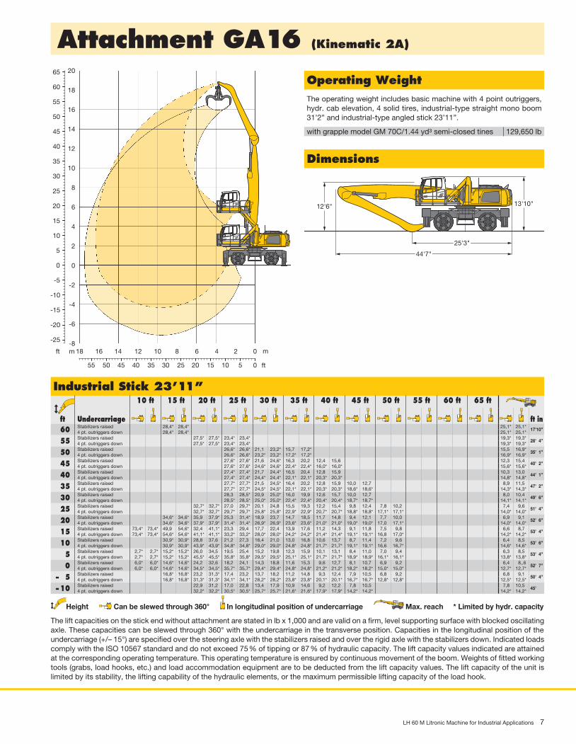
Attachment GA16 (Kinematic 2A)
30
55
60
65
50
45
40
35
25
20
15
10
5
0
-5
-10
-15
-20
-25
8
10
12
14
16
18
20 H0621
3540455055 30 25 20 15 10 5 0
12141618 10 8 6 4 2 0
6
4
2
0
-2
-4
-6
-8mft m
ft
25'3"
44'7"
13'10"
US_H0622
12'6"
Dimensions
Operating WeightThe operating weight includes basic machine with 4 point outriggers, hydr. cab elevation, 4 solid tires, industrial-type straight mono boom 31’2” and industrial-type angled stick 23’11”.
with grapple model GM 70C/1.44 yd3 semi-closed tines 129,650 lb
Industrial Stick 23’11” ft
Undercarriage
10 ft 15 ft 20 ft 25 ft 30 ft 35 ft 40 ft 45 ft 50 ft 55 ft 60 ft 65 ft
ft in 60 Stabilizers raised 28,4* 28,4* 25,1* 25,1*
17’10”4 pt. outriggers down 28,4* 28,4* 25,1* 25,1*
55 Stabilizers raised 27,5* 27,5* 23,4* 23,4* 19,3* 19,3*28’ 4”
4 pt. outriggers down 27,5* 27,5* 23,4* 23,4* 19,3* 19,3*
50 Stabilizers raised 26,6* 26,6* 21,1 23,2* 15,7 17,2* 15,5 16,9*35’ 1”
4 pt. outriggers down 26,6* 26,6* 23,2* 23,2* 17,2* 17,2* 16,9* 16,9*
45 Stabilizers raised 27,6* 27,6* 21,6 24,6* 16,3 20,2 12,4 15,6 12,3 15,440’ 2”
4 pt. outriggers down 27,6* 27,6* 24,6* 24,6* 22,4* 22,4* 16,0* 16,0* 15,6* 15,6*
40 Stabilizers raised 27,4* 27,4* 21,7 24,4* 16,5 20,4 12,8 15,9 10,3 13,044’ 1”
4 pt. outriggers down 27,4* 27,4* 24,4* 24,4* 22,1* 22,1* 20,3* 20,3* 14,8* 14,8*
35 Stabilizers raised 27,7* 27,7* 21,5 24,5* 16,4 20,2 12,8 15,9 10,0 12,7 8,9 11,547’ 2”
4 pt. outriggers down 27,7* 27,7* 24,5* 24,5* 22,1* 22,1* 20,3* 20,3* 18,6* 18,6* 14,3* 14,3*
30 Stabilizers raised 28,3 28,5* 20,9 25,0* 16,0 19,9 12,6 15,7 10,0 12,7 8,0 10,449’ 6”
4 pt. outriggers down 28,5* 28,5* 25,0* 25,0* 22,4* 22,4* 20,4* 20,4* 18,7* 18,7* 14,1* 14,1*
25 Stabilizers raised 32,7* 32,7* 27,0 29,7* 20,1 24,8 15,5 19,3 12,2 15,4 9,8 12,4 7,8 10,2 7,4 9,651’ 4”
4 pt. outriggers down 32,7* 32,7* 29,7* 29,7* 25,8* 25,8* 22,9* 22,9* 20,7* 20,7* 18,8* 18,8* 17,1* 17,1* 14,0* 14,0*
20 Stabilizers raised 34,6* 34,6* 35,9 37,9* 25,3 31,4* 18,9 23,7 14,7 18,5 11,7 14,8 9,4 12,1 7,7 10,0 6,9 9,152’ 6”
4 pt. outriggers down 34,6* 34,6* 37,9* 37,9* 31,4* 31,4* 26,9* 26,9* 23,6* 23,6* 21,0* 21,0* 19,0* 19,0* 17,0 17,1* 14,0* 14,0*
15 Stabilizers raised 73,4* 73,4* 49,9 54,6* 32,4 41,1* 23,3 29,4 17,7 22,4 13,9 17,6 11,2 14,3 9,1 11,8 7,5 9,8 6,6 8,753’ 4”
4 pt. outriggers down 73,4* 73,4* 54,6* 54,6* 41,1* 41,1* 33,2* 33,2* 28,0* 28,0* 24,2* 24,2* 21,4* 21,4* 19,1* 19,1* 16,8 17,0* 14,2* 14,2*
10 Stabilizers raised 30,9* 30,9* 28,8 37,6 21,2 27,3 16,4 21,0 13,0 16,8 10,6 13,7 8,7 11,4 7,2 9,6 6,4 8,553’ 6”
4 pt. outriggers down 30,9* 30,9* 43,9* 43,9* 34,8* 34,8* 29,0* 29,0* 24,8* 24,8* 21,7* 21,7* 19,1* 19,1* 16,6 16,7* 14,6* 14,6*
5 Stabilizers raised 2,7* 2,7* 15,2* 15,2* 26,0 34,5 19,5 25,4 15,2 19,8 12,3 15,9 10,1 13,1 8,4 11,0 7,0 9,4 6,3 8,553’ 4”
4 pt. outriggers down 2,7* 2,7* 15,2* 15,2* 45,5* 45,5* 35,8* 35,8* 29,5* 29,5* 25,1* 25,1* 21,7* 21,7* 18,9* 18,9* 16,1* 16,1* 13,8* 13,8*
0 Stabilizers raised 6,0* 6,0* 14,6* 14,6* 24,2 32,6 18,2 24,1 14,3 18,8 11,6 15,3 9,6 12,7 8,1 10,7 6,9 9,2 6,4 8,,652’ 7”
4 pt. outriggers down 6,0* 6,0* 14,6* 14,6* 34,5* 34,5* 35,7* 35,7* 29,4* 29,4* 24,8* 24,8* 21,2* 21,2* 18,2* 18,2* 15,0* 15,0* 12,7* 12,7*
– 5 Stabilizers raised 16,8* 16,8* 23,2 31,3* 17,4 23,2 13,7 18,2 11,2 14,8 9,3 12,4 7,9 10,5 6,8 9,2 6,8 9,150’ 4”
4 pt. outriggers down 16,8* 16,8* 31,3* 31,3* 34,1* 34,1* 28,2* 28,2* 23,8* 23,8* 20,1* 20,1* 16,7* 16,7* 12,8* 12,8* 12,5* 12,5*
– 10 Stabilizers raised 22,9 31,2 17,0 22,8 13,4 17,9 10,9 14,6 9,2 12,2 7,8 10,5 7,8 10,545’
4 pt. outriggers down 32,2* 32,2* 30,5* 30,5* 25,7* 25,7* 21,6* 21,6* 17,9* 17,9* 14,2* 14,2* 14,2* 14,2*
Height Can be slewed through 360° In longitudinal position of undercarriage Max. reach * Limited by hydr. capacity
The lift capacities on the stick end without attachment are stated in lb x 1,000 and are valid on a firm, level supporting surface with blocked oscillating axle. These capacities can be slewed through 360° with the undercarriage in the transverse position. Capacities in the longitudinal position of the undercarriage (+/– 15°) are specified over the steering axle with the stabilizers raised and over the rigid axle with the stabilizers down. Indicated loads comply with the ISO 10567 standard and do not exceed 75 % of tipping or 87 % of hydraulic capacity. The lift capacity values indicated are attained at the corresponding operating temperature. This operating temperature is ensured by continuous movement of the boom. Weights of fitted working tools (grabs, load hooks, etc.) and load accommodation equipment are to be deducted from the lift capacity values. The lift capacity of the unit is limited by its stability, the lifting capability of the hydraulic elements, or the maximum permissible lifting capacity of the load hook.

8 LH 60 M Litronic Machine for Industrial Applications
Attachment AG17 (Kinematic 2D)
44'2"
13'10"
US_H0610
13'1"
30'6"
3'7"
3'7"
Dimensions
Operating WeightThe operating weight includes basic machine with 4 point outriggers, hydr. cab elevation, 4 solid tires, industrial-type angled mono boom 31’2” and industrial-type straight stick 28’10”.
with clamshell model GM 20B/2.62 yd3
shells for loose material
130,850 lb
Industrial Stick 28’10” ft
Undercarriage
10 ft 15 ft 20 ft 25 ft 30 ft 35 ft 40 ft 45 ft 50 ft 55 ft 60 ft 65 ft
ft in 60 Stabilizers raised 15,8* 15,8*
26’ 7”4 pt. outriggers down 15,8* 15,8*
55 Stabilizers raised 17,6* 17,6* 13,7* 13,7*34’ 6”
4 pt. outriggers down 17,6* 17,6* 13,7* 13,7*
50 Stabilizers raised 17,3* 17,3* 12,8* 12,8* 12,5* 12,5*40’ 4”
4 pt. outriggers down 17,3* 17,3* 12,8* 12,8* 12,5* 12,5*
45 Stabilizers raised 17,6* 17,6* 14,1 16,6* 10,9 11,9*44’ 8”
4 pt. outriggers down 17,6* 17,6* 16,6* 16,6* 11,9* 11,9*
40 Stabilizers raised 17,5* 17,5* 14,3 16,4* 11,1 13,8 9,3 11,4*48’ 4”
4 pt. outriggers down 17,5* 17,5* 16,4* 16,4* 15,2* 15,2* 11,4* 11,4*
35 Stabilizers raised 17,6* 17,6* 14,2 16,4* 11,1 13,9 8,7 11,0 8,2 10,551’ 1”
4 pt. outriggers down 17,6* 17,6* 16,4* 16,4* 15,5* 15,5* 12,8* 12,8* 11,2* 11,2*
30 Stabilizers raised 17,8 18,0* 13,9 16,7* 10,9 13,7 8,6 11,0 7,3 9,553’ 4”
4 pt. outriggers down 18,0* 18,0* 16,7* 16,7* 15,6* 15,6* 14,8* 14,8* 11,1* 11,1*
25 Stabilizers raised 20,5* 20,5* 17,2 18,6* 13,4 16,7 10,6 13,4 8,5 10,8 6,7 8,854’11”
4 pt. outriggers down 20,5* 20,5* 18,6* 18,6* 17,1* 17,1* 15,9* 15,9* 14,9* 14,9* 11,1* 11,1*
20 Stabilizers raised 24,6* 24,6* 21,2 21,7* 16,3 19,4* 12,8 16,0 10,2 13,0 8,2 10,6 6,5 8,6 6,2 8,356’ 1”
4 pt. outriggers down 24,6* 24,6* 21,7* 21,7* 19,4* 19,4* 17,7* 17,7* 16,3* 16,3* 15,2* 15,2* 13,2* 13,2* 11,3* 11,3*
15 Stabilizers raised 32,1* 32,1* 26,4 26,8* 19,7 23,1* 15,3 19,1 12,1 15,3 9,7 12,4 7,8 10,2 6,3 8,4 5,9 7,956’10”
4 pt. outriggers down 32,1* 32,1* 26,8* 26,8* 23,1* 23,1* 20,4* 20,4* 18,4* 18,4* 16,8* 16,8* 15,4* 15,4* 14,3* 14,3* 11,5* 11,5*
10 Stabilizers raised 73,3* 73,3* 47,9* 47,9* 33,3 36,0* 23,9 29,1* 18,1 22,9 14,2 18,0 11,3 14,5 9,2 11,9 7,5 9,8 6,1 8,2 5,6 7,657’
4 pt. outriggers down 73,3* 73,3* 47,9* 47,9* 36,0* 36,0* 29,1* 29,1* 24,6* 24,6* 21,4* 21,4* 19,1* 19,1* 17,2* 17,2* 15,7* 15,7* 14,4* 14,4* 11,9* 11,9*
5 Stabilizers raised 12,5* 12,5* 43,3 45,2* 29,2 38,0 21,4 27,6 16,5 21,2 13,1 16,9 10,6 13,7 8,6 11,3 7,1 9,5 5,9 8,0 5,5 7,556’10”
4 pt. outriggers down 12,5* 12,5* 45,2* 45,2* 39,6* 39,6* 31,3* 31,3* 26,1* 26,1* 22,4* 22,4* 19,7* 19,7* 17,7* 17,7* 15,9* 15,9* 14,2 14,4* 12,4* 12,4*
0 Stabilizers raised 10,9* 10,9* 23,9* 23,9* 25,9 34,5 19,3 25,4 15,1 19,7 12,1 15,8 9,9 13,0 8,1 10,8 6,8 9,1 5,7 7,8 5,4 7,556’ 2”
4 pt. outriggers down 10,9* 10,9* 23,9* 23,9* 42,1* 42,1* 33,1* 33,1* 27,2* 27,2* 23,2* 23,2* 20,3* 20,3* 17,9* 17,9* 16,0* 16,0* 14,0 14,1* 13,0* 13,0*
– 5 Stabilizers raised 12,3* 12,3* 21,0* 21,0* 23,7 32,1 17,8 23,7 14,0 18,5 11,3 15,0 9,3 12,4 7,7 10,4 6,5 8,8 5,5 7,6 5,5 7,655’ 1”
4 pt. outriggers down 12,3* 12,3* 21,0* 21,0* 41,0* 41,0* 34,0* 34,0* 28,0* 28,0* 23,7* 23,7* 20,5* 20,5* 18,0* 18,0* 15,8* 15,8* 13,5* 13,5* 13,4* 13,4*
– 10 Stabilizers raised 14,4* 14,4* 21,3* 21,3* 22,4 30,7 16,7 22,6 13,2 17,7 10,7 14,4 8,8 11,9 7,4 10,1 6,3 8,7 5,7 7,953’ 6”
4 pt. outriggers down 14,4* 14,4* 21,3* 21,3* 35,5* 35,5* 34,0* 34,0* 28,0* 28,0* 23,7* 23,7* 20,3* 20,3* 17,6* 17,6* 15,1* 15,1* 13,1* 13,1*
– 15 Stabilizers raised 22,6* 22,6* 21,8 30,1 16,1 22,0 12,7 17,2 10,3 14,0 8,6 11,7 7,3 9,9 6,3 8,6 6,1 8,351’ 4”
4 pt. outriggers down 22,6* 22,6* 34,6* 34,6* 32,8* 32,8* 27,1* 27,1* 22,9* 22,9* 19,5* 19,5* 16,6* 16,6* 13,5* 13,5* 12,5* 12,5*
– 20 Stabilizers raised 21,7 30,0 16,0 21,8 12,5 17,0 10,2 13,8 8,5 11,6 7,3 10,044’11”
4 pt. outriggers down 35,6* 35,6* 30,0* 30,0* 25,0* 25,0* 21,0* 21,0* 17,6* 17,6* 14,4* 14,4*
Height Can be slewed through 360° In longitudinal position of undercarriage Max. reach * Limited by hydr. capacity
The lift capacities on the stick end without attachment are stated in lb x 1,000 and are valid on a firm, level supporting surface with blocked oscillating axle. These capacities can be slewed through 360° with the undercarriage in the transverse position. Capacities in the longitudinal position of the undercarriage (+/– 15°) are specified over the steering axle with the stabilizers raised and over the rigid axle with the stabilizers down. Indicated loads comply with the ISO 10567 standard and do not exceed 75 % of tipping or 87 % of hydraulic capacity. The lift capacity values indicated are attained at the corresponding operating temperature. This operating temperature is ensured by continuous movement of the boom. Weights of fitted working tools (grabs, load hooks, etc.) and load accommodation equipment are to be deducted from the lift capacity values. The lift capacity of the unit is limited by its stability, the lifting capability of the hydraulic elements, or the maximum permissible lifting capacity of the load hook.
30
55
60
65
50
45
40
35
25
20
15
10
5
0
-5
-10
-15
-20
-25
-30
-35
8
10
12
14
16
18
20 US_H0609
35404550556065 30 25 20 15 10 5 0
1214161820 10 8 6 4 2 0
6
4
2
0
-2
-4
-6
-8
-10
-12mft m
ft

LH 60 M Litronic Machine for Industrial Applications 9
Attachment AG17 (Kinematic 2C)
43'
13'10"
US_H0602
11'4"
30'6"
3'7"
3'7"
Dimensions
Operating WeightThe operating weight includes basic machine with 4 point outriggers, hydr. cab elevation, 4 solid tires, industrial-type angled mono boom 31’2” and industrial-type straight stick 28’10”.
with clamshell model GM 20B/2.62 yd3
shells for loose material
130,850 lb
Industrial Stick 28’10” ft
Undercarriage
10 ft 15 ft 20 ft 25 ft 30 ft 35 ft 40 ft 45 ft 50 ft 55 ft 60 ft 65 ft
ft in 55 Stabilizers raised 13,7* 13,7*
34’ 6”4 pt. outriggers down 13,7* 13,7*
50 Stabilizers raised 12,8* 12,8* 12,5* 12,5*40’ 4”
4 pt. outriggers down 12,8* 12,8* 12,5* 12,5*
45 Stabilizers raised 14,1 15,0* 11,0 11,9*44’ 8”
4 pt. outriggers down 15,0* 15,0* 11,9* 11,9*
40 Stabilizers raised 14,3 14,8* 11,1 13,9 9,3 11,4*48’ 4”
4 pt. outriggers down 14,8* 14,8* 14,3* 14,3* 11,4* 11,4*
35 Stabilizers raised 14,2 14,8* 11,1 13,9 8,7 11,1 8,2 10,551’ 1”
4 pt. outriggers down 14,8* 14,8* 14,2* 14,2* 12,8* 12,8* 11,2* 11,2*
30 Stabilizers raised 13,9 15,1* 11,0 13,7 8,6 11,0 7,3 9,553’ 4”
4 pt. outriggers down 15,1* 15,1* 14,4* 14,4* 13,8* 13,8* 11,1* 11,1*
25 Stabilizers raised 16,7* 16,7* 13,4 15,6* 10,6 13,4 8,5 10,9 6,7 8,854’11”
4 pt. outriggers down 16,7* 16,7* 15,6* 15,6* 14,7* 14,7* 14,0* 14,0* 11,1* 11,1*
20 Stabilizers raised 16,3 17,6* 12,8 16,0 10,2 13,0 8,2 10,6 6,5 8,6 6,2 8,356’ 1”
4 pt. outriggers down 17,6* 17,6* 16,2* 16,2* 15,1* 15,1* 14,3* 14,3* 13,2* 13,2* 11,3* 11,3*
15 Stabilizers raised 19,8 21,0* 15,3 18,7* 12,1 15,3 9,7 12,4 7,9 10,2 6,3 8,4 5,9 7,956’10”
4 pt. outriggers down 21,0* 21,0* 18,7* 18,7* 17,0* 17,0* 15,7* 15,7* 14,6* 14,6* 13,7* 13,7* 11,5* 11,5*
10 Stabilizers raised 66,8* 66,8* 43,6* 43,6* 32,9* 32,9* 23,9 26,7* 18,1 22,7* 14,2 18,0 11,3 14,5 9,2 11,9 7,5 9,8 6,1 8,2 5,6 7,657’
4 pt. outriggers down 66,8* 66,8* 43,6* 43,6* 32,9* 32,9* 26,7* 26,7* 22,7* 22,7* 19,9* 19,9* 17,8* 17,8* 16,3* 16,3* 15,0* 15,0* 13,9* 13,9* 11,9* 11,9*
5 Stabilizers raised 12,5* 12,5* 43,3 45,2* 29,2 36,9* 21,5 27,6 16,5 21,2 13,1 16,9 10,6 13,7 8,6 11,3 7,1 9,5 5,9 8,0 5,5 7,556’10”
4 pt. outriggers down 12,5* 12,5* 45,2* 45,2* 36,9* 36,9* 29,2* 29,2* 24,4* 24,4* 21,1* 21,1* 18,7* 18,7* 16,8* 16,8* 15,4* 15,4* 14,1* 14,1* 12,4* 12,4*
0 Stabilizers raised 10,9* 10,9* 23,9* 23,9* 25,9 34,5 19,3 25,4 15,1 19,7 12,1 15,8 9,9 13,0 8,1 10,8 6,8 9,1 5,7 7,8 5,4 7,556’ 2”
4 pt. outriggers down 10,9* 10,9* 23,9* 23,9* 40,1* 40,1* 31,4* 31,4* 25,9* 25,9* 22,1* 22,1* 19,4* 19,4* 17,3* 17,3* 15,6* 15,6* 14,0 14,1* 13,0* 13,0*
– 5 Stabilizers raised 12,3* 12,3* 21,0* 21,0* 23,7 32,1 17,8 23,7 14,0 18,5 11,3 15,0 9,3 12,4 7,7 10,4 6,5 8,8 5,5 7,6 5,5 7,655’ 1”
4 pt. outriggers down 12,3* 12,3* 21,0* 21,0* 41,0* 41,0* 32,9* 32,9* 27,0* 27,0* 22,9* 22,9* 19,9* 19,9* 17,6* 17,6* 15,7* 15,7* 13,7* 13,7* 13,7* 13,7*
– 10 Stabilizers raised 14,4* 14,4* 21,3* 21,3* 22,4 30,8 16,7 22,6 13,2 17,7 10,7 14,4 8,8 11,9 7,4 10,1 6,3 8,7 5,7 7,953’ 6”
4 pt. outriggers down 14,4* 14,4* 21,3* 21,3* 35,5* 35,5* 33,5* 33,5* 27,5* 27,5* 23,3* 23,3* 20,1* 20,1* 17,6* 17,6* 15,3* 15,3* 13,6* 13,6*
– 15 Stabilizers raised 16,6* 16,6* 22,6* 22,6* 21,8 30,1 16,1 22,0 12,7 17,2 10,3 14,0 8,6 11,7 7,3 9,9 6,3 8,6 6,1 8,351’ 4”
4 pt. outriggers down 16,6* 16,6* 22,6* 22,6* 34,6* 34,6* 33,1* 33,1* 27,3* 27,3* 23,0* 23,0* 19,7* 19,7* 17,0* 17,0* 14,2* 14,2* 13,3* 13,3*
– 20 Stabilizers raised 18,7* 18,7* 24,5* 24,5* 21,7 30,0 16,0 21,8 12,5 17,0 10,2 13,8 8,5 11,6 7,3 9,9 6,6 9,148’ 7”
4 pt. outriggers down 18,7* 18,7* 24,5* 24,5* 35,6* 35,6* 31,2* 31,2* 25,9* 25,9* 21,8* 21,8* 18,5* 18,5* 15,3* 15,3* 12,8* 12,8*
– 25 Stabilizers raised 22,1 30,4 16,1 22,0 12,6 17,1 10,3 13,9 8,6 11,7 7,7 10,444’ 2”
4 pt. outriggers down 33,1* 33,1* 27,5* 27,5* 23,0* 23,0* 19,2* 19,2* 15,7* 15,7* 12,5* 12,5*
Height Can be slewed through 360° In longitudinal position of undercarriage Max. reach * Limited by hydr. capacity
The lift capacities on the stick end without attachment are stated in lb x 1,000 and are valid on a firm, level supporting surface with blocked oscillating axle. These capacities can be slewed through 360° with the undercarriage in the transverse position. Capacities in the longitudinal position of the undercarriage (+/– 15°) are specified over the steering axle with the stabilizers raised and over the rigid axle with the stabilizers down. Indicated loads comply with the ISO 10567 standard and do not exceed 75 % of tipping or 87 % of hydraulic capacity. The lift capacity values indicated are attained at the corresponding operating temperature. This operating temperature is ensured by continuous movement of the boom. Weights of fitted working tools (grabs, load hooks, etc.) and load accommodation equipment are to be deducted from the lift capacity values. The lift capacity of the unit is limited by its stability, the lifting capability of the hydraulic elements, or the maximum permissible lifting capacity of the load hook.
30
55
50
45
40
35
25
20
15
10
5
0
-5
-10
-15
-20
-25
-30
-35
8
10
12
14
16
18 US_H0601
35404550556065 30 25 20 15 10 5 0
1214161820 10 8 6 4 2 0
6
4
2
0
-2
-4
-6
-8
-10
-12mft m
ft

10 LH 60 M Litronic Machine for Industrial Applications
Attachment GA18 (Kinematic 2A)
44'3"
30'6"
3'11"
3'7"
13'10"
US_H0620
12'
Dimensions
Operating WeightThe operating weight includes basic machine with 4 point outriggers, hydr. cab elevation, 4 solid tires, industrial-type straight mono boom 31’2” and industrial-type angled stick 28’10”.
with grapple model GM 70C/1.44 yd3 semi-closed tines 130,300 lb
Industrial Stick 28’10” ft
Undercarriage
10 ft 15 ft 20 ft 25 ft 30 ft 35 ft 40 ft 45 ft 50 ft 55 ft 60 ft 65 ft
ft in 65 Stabilizers raised 22,2* 22,2*
18’ 4 pt. outriggers down 22,2* 22,2*
60 Stabilizers raised 20,7* 20,7* 16,5* 16,5*29’ 4”
4 pt. outriggers down 20,7* 20,7* 16,5* 16,5*
55 Stabilizers raised 20,2* 20,2* 16,3* 16,3* 14,3* 14,3*36’ 7”
4 pt. outriggers down 20,2* 20,2* 16,3* 16,3* 14,3* 14,3*
50 Stabilizers raised 21,9* 21,9* 17,2 19,6* 13,1 15,7* 11,6 13,0*42’ 1”
4 pt. outriggers down 21,9* 21,9* 19,6* 19,6* 15,7* 15,7* 13,0* 13,0*
45 Stabilizers raised 22,4* 22,4* 17,6 20,5* 13,6 16,8 10,4 13,2 9,6 12,2*46’ 5”
4 pt. outriggers down 22,4* 22,4* 20,5* 20,5* 18,8* 18,8* 14,2* 14,2* 12,2* 12,2*
40 Stabilizers raised 22,3* 22,3* 17,6 20,3* 13,7 16,9 10,7 13,4 8,3 10,749’10”
4 pt. outriggers down 22,3* 22,3* 20,3* 20,3* 18,8* 18,8* 17,5* 17,5* 11,6* 11,6*
35 Stabilizers raised 22,4* 22,4* 17,5 20,4* 13,6 16,8 10,7 13,4 8,4 10,8 7,4 9,652’ 7”
4 pt. outriggers down 22,4* 22,4* 20,4* 20,4* 18,8* 18,8* 17,4* 17,4* 15,2* 15,2* 11,3* 11,3*
30 Stabilizers raised 22,3 23,0* 17,1 20,8* 13,3 16,5 10,5 13,3 8,4 10,7 6,7 8,854’ 8”
4 pt. outriggers down 23,0* 23,0* 20,8* 20,8* 19,0* 19,0* 17,5* 17,5* 16,3* 16,3* 11,1* 11,1*
25 Stabilizers raised 25,3* 25,3* 21,5 23,8* 16,4 20,3 12,9 16,1 10,3 13,0 8,2 10,6 6,5 8,6 6,1 8,256’ 4”
4 pt. outriggers down 25,3* 25,3* 23,8* 23,8* 21,3* 21,3* 19,4* 19,4* 17,7* 17,7* 16,3* 16,3* 13,5* 13,5* 11,0* 11,0*
20 Stabilizers raised 27,5 28,6* 20,3 24,9* 15,6 19,5 12,3 15,5 9,9 12,6 8,0 10,3 6,4 8,5 5,8 7,757’ 5”
4 pt. outriggers down 28,6* 28,6* 24,9* 24,9* 22,0* 22,0* 19,8* 19,8* 18,0* 18,0* 16,4* 16,4* 14,7 14,9* 11,1* 11,1*
15 Stabilizers raised 25,1* 25,1* 32,8* 32,8* 25,3 30,6* 18,9 23,7 14,7 18,5 11,7 14,8 9,4 12,1 7,7 10,0 6,3 8,3 5,5 7,558’ 1”
4 pt. outriggers down 25,1* 25,1* 32,8* 32,8* 30,6* 30,6* 26,1* 26,1* 22,8* 22,8* 20,3* 20,3* 18,3* 18,3* 16,6* 16,6* 14,5 14,9* 11,2* 11,2*
10 Stabilizers raised 62,4* 62,4* 49,3 54,1* 32,0 40,5* 23,0 29,2 17,4 22,1 13,7 17,4 11,0 14,1 8,9 11,6 7,3 9,7 6,1 8,1 5,4 7,358’ 4”
4 pt. outriggers down 62,4* 62,4* 54,1* 54,1* 40,5* 40,5* 32,6* 32,6* 27,4* 27,4* 23,6* 23,6* 20,8* 20,8* 18,5* 18,5* 16,6* 16,6* 14,3 14,7* 11,4* 11,4*
5 Stabilizers raised 6,8* 6,8* 33,8* 33,8* 28,3 37,0 20,8 26,8 16,0 20,6 12,7 16,4 10,3 13,4 8,5 11,1 7,0 9,4 5,9 7,9 5,3 7,258’ 1”
4 pt. outriggers down 6,8* 6,8* 33,8* 33,8* 43,4* 43,4* 34,3* 34,3* 28,4* 28,4* 24,3* 24,3* 21,2* 21,2* 18,7* 18,7* 16,4 16,5* 14,1 14,2* 11,8* 11,8*
0 Stabilizers raised 7,1* 7,1* 18,8* 18,8* 25,4 33,9 18,9 24,9 14,8 19,3 11,9 15,5 9,7 12,8 8,0 10,7 6,7 9,1 5,7 7,8 5,3 7,357’ 6”
4 pt. outriggers down 7,1* 7,1* 18,8* 18,8* 44,8* 44,8* 35,2* 35,2* 29,0* 29,0* 24,6* 24,6* 21,2* 21,2* 18,5* 18,5* 16,0* 16,0* 13,4* 13,4* 11,5* 11,5*
– 5 Stabilizers raised 9,4* 9,4* 17,5* 17,5* 23,5 31,9 17,6 23,5 13,8 18,3 11,2 14,8 9,2 12,3 7,7 10,4 6,5 8,9 5,6 7,7 5,5 7,556’ 4”
4 pt. outriggers down 9,4* 9,4* 17,5* 17,5* 36,7* 36,7* 35,1* 35,1* 28,8* 28,8* 24,3* 24,3* 20,8* 20,8* 17,9* 17,9* 15,1* 15,1* 11,8* 11,8* 10,6* 10,6*
– 10 Stabilizers raised 18,9* 18,9* 22,6 30,9 16,8 22,6 13,2 17,7 10,7 14,3 8,9 11,9 7,5 10,1 6,4 8,8 6,0 8,252’ 6”
4 pt. outriggers down 18,9* 18,9* 33,0* 33,0* 33,4* 33,4* 27,6* 27,6* 23,2* 23,2* 19,7* 19,7* 16,5* 16,5* 13,4* 13,4* 11,4* 11,4*
– 15 Stabilizers raised 22,2 30,5 16,4 22,2 12,8 17,3 10,4 14,1 8,7 11,8 7,4 10,1 7,1 9,746’ 4”
4 pt. outriggers down 33,2* 33,2* 29,9* 29,9* 25,0* 25,0* 21,0* 21,0* 17,5* 17,5* 14,2* 14,2* 13,2* 13,2*
– 20 Stabilizers raised4 pt. outriggers down
Height Can be slewed through 360° In longitudinal position of undercarriage Max. reach * Limited by hydr. capacity
The lift capacities on the stick end without attachment are stated in lb x 1,000 and are valid on a firm, level supporting surface with blocked oscillating axle. These capacities can be slewed through 360° with the undercarriage in the transverse position. Capacities in the longitudinal position of the undercarriage (+/– 15°) are specified over the steering axle with the stabilizers raised and over the rigid axle with the stabilizers down. Indicated loads comply with the ISO 10567 standard and do not exceed 75 % of tipping or 87 % of hydraulic capacity. The lift capacity values indicated are attained at the corresponding operating temperature. This operating temperature is ensured by continuous movement of the boom. Weights of fitted working tools (grabs, load hooks, etc.) and load accommodation equipment are to be deducted from the lift capacity values. The lift capacity of the unit is limited by its stability, the lifting capability of the hydraulic elements, or the maximum permissible lifting capacity of the load hook.
30
55
60
65
70
50
45
40
35
25
20
15
10
5
0
-5
-10
-15
-20
-25
-30
8
10
12
14
16
18
20
22US_H0619
35404550556065 30 25 20 15 10 5 0
1214161820 10 8 6 4 2 0
6
4
2
0
-2
-4
-6
-8
-10mft m
ft

LH 60 M Litronic Machine for Industrial Applications 11
Attachment AG19 (Kinematic 2D)
24'7"
50'10"
13'10"
US_H0608
13'5"
Dimensions
Operating WeightThe operating weight includes basic machine with 4 point outriggers, hydr. cab elevation, 4 solid tires, industrial-type angled mono boom 37’9” and industrial-type straight stick 28’10”.
with clamshell model GM 20B/2.62 yd3
shells for loose material
132,950 lb
Industrial Stick 28’10” ft
Undercarriage
10 ft 15 ft 20 ft 25 ft 30 ft 35 ft 40 ft 45 ft 50 ft 55 ft 60 ft 65 ft
ft in 65 Stabilizers raised 15,5* 15,5* 15,1* 15,1*
30’ 6”4 pt. outriggers down 15,5* 15,5* 15,1* 15,1*
60 Stabilizers raised 16,0* 16,0* 13,4* 13,4*38’ 2”
4 pt. outriggers down 16,0* 16,0* 13,4* 13,4*
55 Stabilizers raised 17,1* 17,1* 13,9 15,5* 11,0 12,4*44’ 1”
4 pt. outriggers down 17,1* 17,1* 15,5* 15,5* 12,4* 12,4*
50 Stabilizers raised 16,9* 16,9* 14,3 15,3* 10,9 13,7 8,9 11,448’ 8”
4 pt. outriggers down 16,9* 16,9* 15,3* 15,3* 14,1* 14,1* 11,8* 11,8*
45 Stabilizers raised 16,8* 16,8* 14,3 15,3* 11,1 13,9 8,5 10,9 7,4 9,752’ 6”
4 pt. outriggers down 16,8* 16,8* 15,3* 15,3* 14,0* 14,0* 13,0* 13,0* 11,4* 11,4*
40 Stabilizers raised 16,9* 16,9* 14,2 15,3* 11,0 13,8 8,6 11,0 6,5 8,6 6,3 8,455’ 6”
4 pt. outriggers down 16,9* 16,9* 15,3* 15,3* 14,0* 14,0* 13,0* 13,0* 11,9* 11,9* 11,2* 11,2*
35 Stabilizers raised 17,2* 17,2* 13,8 15,5* 10,8 13,6 8,4 10,8 6,5 8,6 5,5 7,558’
4 pt. outriggers down 17,2* 17,2* 15,5* 15,5* 14,1* 14,1* 13,0* 13,0* 12,1* 12,1* 11,1* 11,1*
30 Stabilizers raised 20,0* 20,0* 17,0 17,6* 13,2 15,8* 10,3 13,1 8,1 10,6 6,4 8,5 4,8 6,859’11”
4 pt. outriggers down 20,0* 20,0* 17,6* 17,6* 15,8* 15,8* 14,3* 14,3* 13,2* 13,2* 12,2* 12,2* 11,1* 11,1*
25 Stabilizers raised 24,4* 24,4* 20,8* 20,8* 15,9 18,2* 12,4 15,7 9,8 12,6 7,8 10,2 6,1 8,2 4,7 6,6 4,4 6,261’ 5”
4 pt. outriggers down 24,4* 24,4* 20,8* 20,8* 18,2* 18,2* 16,2* 16,2* 14,6* 14,6* 13,3* 13,3* 12,3* 12,3* 11,4* 11,4* 11,1* 11,1*
20 Stabilizers raised 41,7* 41,7* 31,8* 31,8* 25,6 25,8* 19,0 21,7* 14,7 18,5 11,5 14,7 9,1 11,9 7,3 9,7 5,8 7,9 4,5 6,4 4,0 5,862’ 5”
4 pt. outriggers down 41,7* 41,7* 31,8* 31,8* 25,8* 25,8* 21,7* 21,7* 18,8* 18,8* 16,6* 16,6* 14,9* 14,9* 13,5* 13,5* 12,4* 12,4* 11,4* 11,4* 10,9* 10,9*
15 Stabilizers raised 46,5* 46,5* 31,1 34,3* 22,5 27,3* 17,0 21,8 13,3 17,1 10,5 13,7 8,4 11,2 6,8 9,2 5,4 7,5 4,3 6,2 3,7 5,563’ 1”
4 pt. outriggers down 46,5* 46,5* 34,3* 34,3* 27,3* 27,3* 22,7* 22,7* 19,5* 19,5* 17,1* 17,1* 15,2* 15,2* 13,7* 13,7* 12,5* 12,5* 11,4* 11,4* 10,7 10,8*
10 Stabilizers raised 14,2* 14,2* 25,8 34,5 19,3 25,4 15,0 19,7 11,9 15,6 9,5 12,7 7,7 10,4 6,2 8,6 5,0 7,2 4,0 5,9 3,5 5,263’ 4”
4 pt. outriggers down 14,2* 14,2* 36,6* 36,6* 28,7* 28,7* 23,6* 23,6* 20,1* 20,1* 17,5* 17,5* 15,5* 15,5* 13,9* 13,9* 12,6* 12,6* 11,4* 11,4* 10,5 10,7*
5 Stabilizers raised 9,2* 9,2* 21,6 24,3* 16,6 22,6 13,1 17,7 10,6 14,3 8,6 11,7 7,0 9,7 5,7 8,1 4,7 6,8 3,8 5,7 3,3 5,163’ 1”
4 pt. outriggers down 9,2* 9,2* 24,3* 24,3* 29,8* 29,8* 24,4* 24,4* 20,6* 20,6* 17,9* 17,9* 15,8* 15,8* 14,1* 14,1* 12,7* 12,7* 11,3 11,4* 10,4 10,5*
0 Stabilizers raised 4,4* 4,4* 9,4* 9,4* 18,8 18,9* 14,5 20,4 11,6 16,2 9,5 13,2 7,8 10,9 6,4 9,1 5,3 7,6 4,4 6,5 3,6 5,5 3,2 5,062’ 6”
4 pt. outriggers down 4,4* 4,4* 9,4* 9,4* 18,9* 18,9* 30,3* 30,3* 24,9* 24,9* 21,0* 21,0* 18,1* 18,1* 15,9* 15,9* 14,1* 14,1* 12,6* 12,6* 11,1 11,1* 10,3* 10,3*
– 5 Stabilizers raised 10,9* 10,9* 17,3 18,0* 13,2 19,0 10,5 15,0 8,6 12,2 7,1 10,2 5,9 8,6 4,9 7,3 4,1 6,2 3,4 5,3 3,3 5,161’ 6”
4 pt. outriggers down 10,9* 10,9* 18,0* 18,0* 30,2* 30,2* 24,9* 24,9* 21,0* 21,0* 18,1* 18,1* 15,8* 15,8* 14,0* 14,0* 12,3* 12,3* 10,7* 10,7* 10,1* 10,1*
– 10 Stabilizers raised 12,9* 12,9* 16,5 18,8* 12,3 18,1 9,8 14,2 8,0 11,6 6,6 9,7 5,5 8,2 4,6 7,0 3,9 6,0 3,4 5,2 3,3 5,260’ 1”
4 pt. outriggers down 12,9* 12,9* 18,8* 18,8* 29,3* 29,3* 24,4* 24,4* 20,7* 20,7* 17,8* 17,8* 15,5* 15,5* 13,6* 13,6* 11,8* 11,8* 9,8* 9,8* 9,7* 9,7*
– 15 Stabilizers raised 16,4 20,2* 12,0 17,7 9,4 13,8 7,6 11,2 6,3 9,4 5,3 7,9 4,5 6,8 3,8 5,9 3,5 5,558’ 2”
4 pt. outriggers down 20,2* 20,2* 27,4* 27,4* 23,1* 23,1* 19,8* 19,8* 17,0* 17,0* 14,8* 14,8* 12,7* 12,7* 10,7* 10,7* 9,2* 9,2*
– 20 Stabilizers raised 12,0 17,7 9,2 13,7 7,4 11,1 6,2 9,2 5,2 7,8 4,4 6,8 4,1 6,353’
4 pt. outriggers down 24,5* 24,5* 21,1* 21,1* 18,2* 18,2* 15,7* 15,7* 13,4* 13,4* 11,3* 11,3* 9,9* 9,9*
Height Can be slewed through 360° In longitudinal position of undercarriage Max. reach * Limited by hydr. capacity
The lift capacities on the stick end without attachment are stated in lb x 1,000 and are valid on a firm, level supporting surface with blocked oscillating axle. These capacities can be slewed through 360° with the undercarriage in the transverse position. Capacities in the longitudinal position of the undercarriage (+/– 15°) are specified over the steering axle with the stabilizers raised and over the rigid axle with the stabilizers down. Indicated loads comply with the ISO 10567 standard and do not exceed 75 % of tipping or 87 % of hydraulic capacity. The lift capacity values indicated are attained at the corresponding operating temperature. This operating temperature is ensured by continuous movement of the boom. Weights of fitted working tools (grabs, load hooks, etc.) and load accommodation equipment are to be deducted from the lift capacity values. The lift capacity of the unit is limited by its stability, the lifting capability of the hydraulic elements, or the maximum permissible lifting capacity of the load hook.
30
55
60
65
70
50
45
40
35
25
20
15
10
5
0
-5
-10
-15
-20
-25
-30
-35
8
10
12
14
16
18
20
22 US_H0607
3540455055606570 30 25 20 15 10 5 0
121416182022 10 8 6 4 2 0
6
4
2
0
-2
-4
-6
-8
-10
-12mft m
ft

12 LH 60 M Litronic Machine for Industrial Applications
Attachment AG19 (Kinematic 2C)
24'7"
50'10"
13'10"
US_H0600
13'5"
Dimensions
Operating WeightThe operating weight includes basic machine with 4 point outriggers, hydr. cab elevation, 4 solid tires, industrial-type angled mono boom 37’9” and industrial-type straight stick 28’10”.
with clamshell model GM 20B/2.62 yd3
shells for loose material
132,950 lb
Industrial Stick 28’10” m
Undercarriage
10 ft 15 ft 20 ft 25 ft 30 ft 35 ft 40 ft 45 ft 50 ft 55 ft 60 ft 65 ft
ft in 60 Stabilizers raised 13,4* 13,4*
38’ 2”4 pt. outriggers down 13,4* 13,4*
55 Stabilizers raised 13,9 13,9* 11,0 12,4*44’ 1”
4 pt. outriggers down 13,9* 13,9* 12,4* 12,4*
50 Stabilizers raised 11,0 12,8* 8,9 11,448’ 8”
4 pt. outriggers down 12,8* 12,8* 11,8* 11,8*
45 Stabilizers raised 11,1 12,6* 8,5 11,0 7,4 9,752’ 6”
4 pt. outriggers down 12,6* 12,6* 11,9* 11,9* 11,4* 11,4*
40 Stabilizers raised 11,0 12,7* 8,6 11,0 6,5 8,7 6,3 8,455’ 6”
4 pt. outriggers down 12,7* 12,7* 11,8* 11,8* 11,2* 11,2* 11,2* 11,2*
35 Stabilizers raised 13,8 13,9* 10,8 12,8* 8,4 10,9 6,5 8,7 5,5 7,558’
4 pt. outriggers down 13,9* 13,9* 12,8* 12,8* 11,9* 11,9* 11,2* 11,2* 10,9* 10,9*
30 Stabilizers raised 13,2 14,2* 10,4 13,0* 8,2 10,6 6,4 8,5 4,9 6,859’11”
4 pt. outriggers down 14,2* 14,2* 13,0* 13,0* 12,1* 12,1* 11,3* 11,3* 10,7* 10,7*
25 Stabilizers raised 15,9 16,4* 12,4 14,7* 9,8 12,6 7,8 10,2 6,1 8,2 4,7 6,6 4,4 6,261’ 5”
4 pt. outriggers down 16,4* 16,4* 14,7* 14,7* 13,3* 13,3* 12,3* 12,3* 11,4* 11,4* 10,7* 10,7* 10,6* 10,6*
20 Stabilizers raised 19,1 19,6* 14,7 17,1* 11,5 14,7 9,2 11,9 7,3 9,7 5,8 7,9 4,5 6,4 4,0 5,862’ 5”
4 pt. outriggers down 19,6* 19,6* 17,1* 17,1* 15,2* 15,2* 13,7* 13,7* 12,6* 12,6* 11,6* 11,6* 10,8* 10,8* 10,5* 10,5*
15 Stabilizers raised 42,4* 42,4* 31,1 31,2* 22,5 24,8* 17,0 20,7* 13,3 17,1 10,5 13,7 8,4 11,2 6,8 9,2 5,4 7,5 4,3 6,2 3,7 5,563’ 1”
4 pt. outriggers down 42,4* 42,4* 31,2* 31,2* 24,8* 24,8* 20,7* 20,7* 17,9* 17,9* 15,8* 15,8* 14,1* 14,1* 12,9* 12,9* 11,8* 11,8* 11,0* 11,0* 10,5* 10,5*
10 Stabilizers raised 14,2* 14,2* 25,8 34,0* 19,3 25,5 15,0 19,7 11,9 15,7 9,5 12,7 7,7 10,4 6,3 8,6 5,1 7,2 4,0 5,9 3,5 5,263’ 4”
4 pt. outriggers down 14,2* 14,2* 34,0* 34,0* 26,6* 26,6* 21,9* 21,9* 18,7* 18,7* 16,3* 16,3* 14,6* 14,6* 13,2* 13,2* 12,0* 12,0* 11,1* 11,1* 10,4* 10,4*
5 Stabilizers raised 9,2* 9,2* 21,6 24,3* 16,6 22,6 13,1 17,8 10,6 14,3 8,6 11,7 7,0 9,7 5,7 8,1 4,7 6,8 3,8 5,7 3,3 5,163’ 1”
4 pt. outriggers down 9,2* 9,2* 24,3* 24,3* 28,1* 28,1* 22,9* 22,9* 19,4* 19,4* 16,9* 16,9* 15,0* 15,0* 13,4* 13,4* 12,2* 12,2* 11,1* 11,1* 10,4 10,4*
0 Stabilizers raised 4,4* 4,4* 9,4* 9,4* 18,8 18,9* 14,5 20,4 11,6 16,2 9,5 13,2 7,8 10,9 6,4 9,1 5,3 7,6 4,4 6,5 3,6 5,5 3,2 5,062’ 6”
4 pt. outriggers down 4,4* 4,4* 9,4* 9,4* 18,9* 18,9* 29,1* 29,1* 23,8* 23,8* 20,0* 20,0* 17,3* 17,3* 15,3* 15,3* 13,6* 13,6* 12,3* 12,3* 11,0* 11,0* 10,4 10,4*
– 5 Stabilizers raised 7,1* 7,1* 10,9* 10,9* 17,3 18,0* 13,2 19,0 10,5 15,0 8,6 12,3 7,1 10,2 5,9 8,6 4,9 7,3 4,1 6,2 3,4 5,3 3,3 5,161’ 6”
4 pt. outriggers down 7,1* 7,1* 10,9* 10,9* 18,0* 18,0* 29,6* 29,6* 24,2* 24,2* 20,4* 20,4* 17,6* 17,6* 15,4* 15,4* 13,7* 13,7* 12,2* 12,2* 10,8* 10,8* 10,3* 10,3*
– 10 Stabilizers raised 9,6* 9,6* 12,9* 12,9* 16,5 18,8* 12,4 18,1 9,8 14,2 8,0 11,6 6,6 9,7 5,5 8,2 4,6 7,0 3,9 6,0 3,4 5,2 3,3 5,260’ 1”
4 pt. outriggers down 9,6* 9,6* 12,9* 12,9* 18,8* 18,8* 29,3* 29,3* 24,2* 24,2* 20,4* 20,4* 17,6* 17,6* 15,4* 15,4* 13,6* 13,6* 11,9* 11,9* 10,2* 10,2* 10,2* 10,2*
– 15 Stabilizers raised 14,9* 14,9* 16,3 20,2* 12,0 17,7 9,4 13,8 7,6 11,2 6,3 9,4 5,3 7,9 4,5 6,8 3,8 5,9 3,5 5,558’ 2”
4 pt. outriggers down 14,9* 14,9* 20,2* 20,2* 28,1* 28,1* 23,5* 23,5* 20,0* 20,0* 17,2* 17,2* 15,0* 15,0* 13,1* 13,1* 11,2* 11,2* 9,9* 9,9*
– 20 Stabilizers raised 16,9* 16,9* 16,5 21,9* 11,9 17,7 9,2 13,7 7,4 11,1 6,2 9,2 5,2 7,8 4,4 6,8 3,9 6,0 3,8 5,955’10”
4 pt. outriggers down 16,9* 16,9* 21,9* 21,9* 26,0* 26,0* 22,1* 22,1* 18,9* 18,9* 16,3* 16,3* 14,1* 14,1* 12,0* 12,0* 9,8* 9,8* 9,4* 9,4*
– 25 Stabilizers raised 17,1 23,9* 12,2 18,0 9,4 13,8 7,5 11,1 6,2 9,3 5,3 7,9 4,6 6,9 4,3 6,552’10”
4 pt. outriggers down 23,9* 23,9* 22,8* 22,8* 19,7* 19,7* 17,0* 17,0* 14,6* 14,6* 12,4* 12,4* 10,1* 10,1* 8,6* 8,6*
– 30 Stabilizers raised 9,7 14,2 7,8 11,4 6,5 9,6 5,9 8,742’11”
4 pt. outriggers down 16,1* 16,1* 14,0* 14,0* 11,9* 11,9* 10,6* 10,6*
Height Can be slewed through 360° In longitudinal position of undercarriage Max. reach * Limited by hydr. capacity
The lift capacities on the stick end without attachment are stated in lb x 1,000 and are valid on a firm, level supporting surface with blocked oscillating axle. These capacities can be slewed through 360° with the undercarriage in the transverse position. Capacities in the longitudinal position of the undercarriage (+/– 15°) are specified over the steering axle with the stabilizers raised and over the rigid axle with the stabilizers down. Indicated loads comply with the ISO 10567 standard and do not exceed 75 % of tipping or 87 % of hydraulic capacity. The lift capacity values indicated are attained at the corresponding operating temperature. This operating temperature is ensured by continuous movement of the boom. Weights of fitted working tools (grabs, load hooks, etc.) and load accommodation equipment are to be deducted from the lift capacity values. The lift capacity of the unit is limited by its stability, the lifting capability of the hydraulic elements, or the maximum permissible lifting capacity of the load hook.
30
55
60
65
50
45
40
35
25
20
15
10
5
0
-5
-10
-15
-20
-25
-30
-35
-40
-45
8
10
12
14
16
18
20 US_H0599
3540455055606570 30 25 20 15 10 5 0
121416182022 10 8 6 4 2 0
6
4
2
0
-2
-4
-6
-8
-10
-12
-14mft m
ft
LH 60 M Litronic Machine for Industrial Applications 13
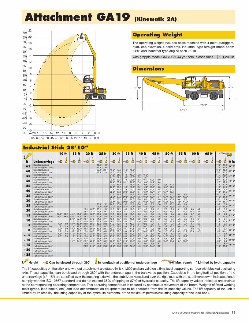
Attachment GA19 (Kinematic 2A)
23'9"
47'9"
13'10"
US_H0618
13'9"
Dimensions
Operating WeightThe operating weight includes basic machine with 4 point outriggers, hydr. cab elevation, 4 solid tires, industrial-type straight mono boom 34’5” and industrial-type angled stick 28’10”.
with grapple model GM 70C/1.44 yd3 semi-closed tines 131,200 lb
Industrial Stick 28’10” ft
Undercarriage
10 ft 15 ft 20 ft 25 ft 30 ft 35 ft 40 ft 45 ft 50 ft 55 ft 60 ft 65 ft
ft in 65 Stabilizers raised 19,5* 19,5* 17,9* 17,9*
26’ 8”4 pt. outriggers down 19,5* 19,5* 17,9* 17,9*
60 Stabilizers raised 22,4* 22,4* 19,6* 19,6* 15,3* 15,3* 15,0* 15,0*35’ 4”
4 pt. outriggers down 22,4* 22,4* 19,6* 19,6* 15,3* 15,3* 15,0* 15,0*
55 Stabilizers raised 21,6* 21,6* 17,0 19,2* 12,8 15,3* 11,7 13,4*41’ 6”
4 pt. outriggers down 21,6* 21,6* 19,2* 19,2* 15,3* 15,3* 13,4* 13,4*
50 Stabilizers raised 22,4* 22,4* 17,5 20,1* 13,4 16,7 10,3 13,0 9,4 12,046’ 5”
4 pt. outriggers down 22,4* 22,4* 20,1* 20,1* 18,4* 18,4* 14,4* 14,4* 12,5* 12,5*
45 Stabilizers raised 22,2* 22,2* 17,7 19,9* 13,7 16,9 10,6 13,3 8,1 10,5 7,9 10,350’ 5”
4 pt. outriggers down 22,2* 22,2* 19,9* 19,9* 18,2* 18,2* 16,8* 16,8* 12,4* 12,4* 11,9* 11,9*
40 Stabilizers raised 22,3* 22,3* 17,6 20,0* 13,6 16,9 10,7 13,4 8,3 10,7 6,8 9,053’ 6”
4 pt. outriggers down 22,3* 22,3* 20,0* 20,0* 18,1* 18,1* 16,7* 16,7* 15,4* 15,4* 11,5* 11,5*
35 Stabilizers raised 22,6* 22,6* 17,2 20,2* 13,4 16,6 10,5 13,3 8,3 10,7 6,4 8,5 6,1 8,156’ 1”
4 pt. outriggers down 22,6* 22,6* 20,2* 20,2* 18,3* 18,3* 16,7* 16,7* 15,4* 15,4* 13,0* 13,0* 11,2* 11,2*
30 Stabilizers raised 21,9 23,1* 16,7 20,5* 13,0 16,2 10,3 13,0 8,1 10,5 6,4 8,5 5,5 7,458’ 1”
4 pt. outriggers down 23,1* 23,1* 20,5* 20,5* 18,5* 18,5* 16,9* 16,9* 15,5* 15,5* 14,2* 14,2* 11,1* 11,1*
25 Stabilizers raised 26,9* 26,9* 20,7 23,9* 15,9 19,7 12,4 15,6 9,9 12,6 7,9 10,2 6,3 8,4 5,0 6,959’ 7”
4 pt. outriggers down 26,9* 26,9* 23,9* 23,9* 21,1* 21,1* 18,9* 18,9* 17,1* 17,1* 15,6* 15,6* 14,2* 14,2* 11,0* 11,0*
20 Stabilizers raised 28,3* 28,3* 26,1 29,2* 19,3 24,1 14,9 18,7 11,7 14,9 9,4 12,1 7,5 9,9 6,1 8,2 4,8 6,7 4,7 6,560’ 8”
4 pt. outriggers down 28,3* 28,3* 29,2* 29,2* 24,9* 24,9* 21,7* 21,7* 19,3* 19,3* 17,3* 17,3* 15,7* 15,7* 14,2* 14,2* 12,3 12,5* 11,1* 11,1*
15 Stabilizers raised 38,2* 38,2* 45,4* 45,4* 33,2 38,3* 23,6 29,8 17,7 22,4 13,8 17,6 11,0 14,1 8,8 11,5 7,2 9,5 5,8 7,9 4,7 6,6 4,5 6,361’ 4”
4 pt. outriggers down 38,2* 38,2* 45,4* 45,4* 38,3* 38,3* 30,8* 30,8* 25,9* 25,9* 22,4* 22,4* 19,7* 19,7* 17,6* 17,6* 15,8* 15,8* 14,1 14,2* 12,1 12,5* 11,2* 11,2*
10 Stabilizers raised 37,2* 37,2* 28,7 37,5 21,0 27,1 16,1 20,7 12,7 16,4 10,2 13,3 8,3 10,9 6,8 9,1 5,6 7,6 4,6 6,4 4,3 6,161’ 6”
4 pt. outriggers down 37,2* 37,2* 40,9* 40,9* 32,4* 32,4* 26,9* 26,9* 23,0* 23,0* 20,0* 20,0* 17,7* 17,7* 15,8* 15,8* 13,8 14,1* 12,0 12,2* 11,4* 11,4*
5 Stabilizers raised 1,9* 1,9* 12,4* 12,4* 24,9 33,5 18,6 24,6 14,5 19,1 11,6 15,3 9,4 12,5 7,7 10,4 6,4 8,7 5,3 7,4 4,4 6,3 4,2 6,161’ 4”
4 pt. outriggers down 1,9* 1,9* 12,4* 12,4* 42,6* 42,6* 33,5* 33,5* 27,6* 27,6* 23,4* 23,4* 20,3* 20,3* 17,8* 17,8* 15,7* 15,7* 13,6 13,8* 11,6* 11,6* 10,7* 10,7*
0 Stabilizers raised 3,9* 3,9* 10,7* 10,7* 22,3 26,0* 16,8 22,7 13,2 17,8 10,7 14,4 8,8 11,8 7,3 9,9 6,1 8,4 5,1 7,2 4,3 6,2 4,3 6,160’ 8”
4 pt. outriggers down 3,9* 3,9* 10,7* 10,7* 26,0* 26,0* 33,8* 33,8* 27,7* 27,7* 23,4* 23,4* 20,2* 20,2* 17,6* 17,6* 15,3* 15,3* 13,2* 13,2* 10,5* 10,5* 10,0* 100*
– 5 Stabilizers raised 6,6* 6,6* 11,9* 11,9* 20,7 22,6* 15,6 21,4 12,3 16,8 10,0 13,6 8,2 11,3 6,9 9,5 5,8 8,1 5,0 7,0 4,4 6,359’ 7”
4 pt. outriggers down 6,6* 6,6* 11,9* 11,9* 22,6* 22,6* 32,9* 32,9* 27,2* 27,2* 23,0* 23,0* 19,7* 19,7* 17,0* 17,0* 14,6* 14,6* 12,2* 12,2* 9,1* 9,1*
– 10 Stabilizers raised 14,1* 14,1* 20,0 22,7* 14,9 20,6 11,7 16,2 9,5 13,1 7,9 10,9 6,6 9,3 5,6 8,0 4,9 7,0 4,8 6,855’10”
4 pt. outriggers down 14,1* 14,1* 22,7* 22,7* 30,7* 30,7* 25,7* 25,7* 21,8* 21,8* 18,6* 18,6* 15,8* 15,8* 13,3* 13,3* 10,4* 10,4* 9,8* 9,8*
– 15 Stabilizers raised 19,9 24,3* 14,6 20,3 11,4 15,8 9,2 12,9 7,7 10,7 6,5 9,1 5,7 8,049’ 7”
4 pt. outriggers down 24,3* 24,3* 26,9* 26,9* 23,0* 23,0* 19,6* 19,6* 16,6* 16,6* 13,9* 13,9* 11,3* 11,3*
– 20 Stabilizers raised4 pt. outriggers down
– 25 Stabilizers raised4 pt. outriggers down
Height Can be slewed through 360° In longitudinal position of undercarriage Max. reach * Limited by hydr. capacity
The lift capacities on the stick end without attachment are stated in lb x 1,000 and are valid on a firm, level supporting surface with blocked oscillating axle. These capacities can be slewed through 360° with the undercarriage in the transverse position. Capacities in the longitudinal position of the undercarriage (+/– 15°) are specified over the steering axle with the stabilizers raised and over the rigid axle with the stabilizers down. Indicated loads comply with the ISO 10567 standard and do not exceed 75 % of tipping or 87 % of hydraulic capacity. The lift capacity values indicated are attained at the corresponding operating temperature. This operating temperature is ensured by continuous movement of the boom. Weights of fitted working tools (grabs, load hooks, etc.) and load accommodation equipment are to be deducted from the lift capacity values. The lift capacity of the unit is limited by its stability, the lifting capability of the hydraulic elements, or the maximum permissible lifting capacity of the load hook.
30
55
60
65
70
50
45
40
35
25
20
15
10
5
0
-5
-10
-15
-20
-25
-30
8
10
12
14
16
18
20
22 US_H0617
35404550556065 30 25 20 15 10 5 0
1214161820 10 8 6 4 2 0
6
4
2
0
-2
-4
-6
-8
-10mft m
ft

14 LH 60 M Litronic Machine for Industrial Applications
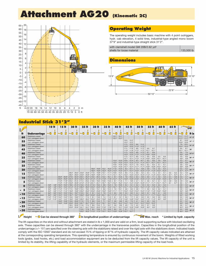
Attachment AG20 (Kinematic 2D)
22'6"
50'10"
13'10"
US_H0606
13'9"
Dimensions
Operating WeightThe operating weight includes basic machine with 4 point outriggers, hydr. cab elevation, 4 solid tires, industrial-type angled mono boom 37’9” and industrial-type straight stick 31’2”.
with clamshell model GM 20B/2.62 yd3
shells for loose material
133,500 lb
Industrial Stick 31’2” ft
Undercarriage
10 ft 15 ft 20 ft 25 ft 30 ft 35 ft 40 ft 45 ft 50 ft 55 ft 60 ft 65 ft
ft in 65 Stabilizers raised 12,9* 12,9*
34’ 8”4 pt. outriggers down 12,9* 12,9*
60 Stabilizers raised 16,1* 16,1* 13,1* 13,1* 11,7* 11,7*41’ 8”
4 pt. outriggers down 16,1* 16,1* 13,1* 13,1* 11,7* 11,7*
55 Stabilizers raised 14,4 14,8* 10,9 12,8* 9,7 10,9*47’ 1”
4 pt. outriggers down 14,8* 14,8* 12,8* 12,8* 10,9* 10,9*
50 Stabilizers raised 14,6* 14,6* 11,3 13,4* 8,6 11,0 7,8 10,251’ 6”
4 pt. outriggers down 14,6* 14,6* 13,4* 13,4* 11,9* 11,9* 10,4* 10,4*
45 Stabilizers raised 14,6* 14,6* 11,4 13,4* 8,8 11,2 6,6 8,7 6,6 8,755’
4 pt. outriggers down 14,6* 14,6* 13,4* 13,4* 12,4* 12,4* 10,1* 10,1* 10,1* 10,1*
40 Stabilizers raised 14,5 14,6* 11,3 13,4* 8,8 11,2 6,7 8,8 5,6 7,657’11”
4 pt. outriggers down 14,6* 14,6* 13,4* 13,4* 12,4* 12,4* 11,5* 11,5* 9,9* 9,9*
35 Stabilizers raised 16,5* 16,5* 14,1 14,8* 11,0 13,5* 8,6 11,0 6,6 8,8 5,0 6,9 4,9 6,860’ 4”
4 pt. outriggers down 16,5* 16,5* 14,8* 14,8* 13,5* 13,5* 12,4* 12,4* 11,5* 11,5* 10,2* 10,2* 9,8* 9,8*
30 Stabilizers raised 16,9* 16,9* 13,5 15,1* 10,6 13,4 8,3 10,7 6,4 8,6 4,9 6,8 4,3 6,162’ 2”
4 pt. outriggers down 16,9* 16,9* 15,1* 15,1* 13,7* 13,7* 12,6* 12,6* 11,6* 11,6* 10,8* 10,8* 9,8* 9,8*
25 Stabilizers raised 19,9* 19,9* 16,4 17,4* 12,7 15,5* 10,0 12,8 7,9 10,3 6,2 8,3 4,7 6,7 3,8 5,663’ 7”
4 pt. outriggers down 19,9* 19,9* 17,4* 17,4* 15,5* 15,5* 14,0* 14,0* 12,8* 12,8* 11,7* 11,7* 10,9* 10,9* 9,9* 9,9*
20 Stabilizers raised 24,6* 24,6* 19,8 20,8* 15,1 18,1* 11,8 15,1 9,3 12,1 7,4 9,8 5,8 7,9 4,5 6,4 3,5 5,264’ 7”
4 pt. outriggers down 24,6* 24,6* 20,8* 20,8* 18,1* 18,1* 16,0* 16,0* 14,3* 14,3* 13,0* 13,0* 11,9* 11,9* 10,9* 10,9* 10,1* 10,1*
15 Stabilizers raised 43,9* 43,9* 32,8* 32,8* 23,7 26,2* 17,8 21,8* 13,7 17,6 10,8 14,0 8,6 11,3 6,8 9,2 5,4 7,5 4,2 6,1 3,2 5,0 3,2 4,965’ 2”
4 pt. outriggers down 43,9* 43,9* 32,8* 32,8* 26,2* 26,2* 21,8* 21,8* 18,7* 18,7* 16,4* 16,4* 14,7* 14,7* 13,2* 13,2* 12,0* 12,0* 11,0* 11,0* 10,0* 10,0* 10,0 10,0*
10 Stabilizers raised 25,9* 25,9* 27,8 35,2* 20,4 26,6 15,6 20,3 12,2 16,0 9,7 12,9 7,8 10,5 6,3 8,6 5,0 7,1 3,9 5,9 3,1 4,8 3,0 4,765’ 5”
4 pt. outriggers down 25,9* 25,9* 35,2* 35,2* 27,7* 27,7* 22,8* 22,8* 19,4* 19,4* 16,9* 16,9* 15,0* 15,0* 13,4* 13,4* 12,2* 12,2* 11,1* 11,1* 9,9 10,0* 9,7 9,9*
5 Stabilizers raised 11,8* 11,8* 23,0 31,6 17,4 23,5 13,6 18,3 10,8 14,6 8,7 11,9 7,0 9,8 5,7 8,1 4,6 6,7 3,7 5,6 2,9 4,6 2,8 4,665’ 2”
4 pt. outriggers down 11,8* 11,8* 32,8* 32,8* 28,9* 28,9* 23,7* 23,7* 20,0* 20,0* 17,3* 17,3* 15,3* 15,3* 13,6* 13,6* 12,3* 12,3* 11,1* 11,1* 9,7 9,8* 9,6 9,8*
0 Stabilizers raised 4,8* 4,8* 10,3* 10,3* 19,6 21,3* 15,0 21,0 11,9 16,5 9,6 13,3 7,8 10,9 6,4 9,1 5,2 7,6 4,2 6,3 3,4 5,3 2,8 4,564’ 8”
4 pt. outriggers down 4,8* 4,8* 10,3* 10,3* 21,3* 21,3* 29,7* 29,7* 24,3* 24,3* 20,4* 20,4* 17,6* 17,6* 15,5* 15,5* 13,7* 13,7* 12,3* 12,3* 10,9 10,9* 9,6 9,6*
– 5 Stabilizers raised 6,9* 6,9* 11,0* 11,0* 17,5 18,8* 13,3 19,2 10,6 15,1 8,6 12,3 7,0 10,1 5,8 8,5 4,8 7,1 3,9 6,0 3,2 5,1 2,8 4,563’ 8”
4 pt. outriggers down 6,9* 6,9* 11,0* 11,0* 18,8* 18,8* 29,9* 29,9* 24,5* 24,5* 20,6* 20,6* 17,8* 17,8* 15,5* 15,5* 13,7* 13,7* 12,1* 12,1* 10,6* 10,6* 9,4* 9,4*
– 10 Stabilizers raised 12,5* 12,5* 16,4 18,7* 12,3 18,0 9,7 14,2 7,9 11,5 6,5 9,5 5,3 8,0 4,4 6,8 3,7 5,8 3,1 4,9 2,8 4,662’ 4”
4 pt. outriggers down 12,5* 12,5* 18,7* 18,7* 29,4* 29,4* 24,2* 24,2* 20,5* 20,5* 17,6* 17,6* 15,3* 15,3* 13,4* 13,4* 11,7* 11,7* 10,0* 10,0* 9,1* 9,1*
– 15 Stabilizers raised 14,2* 14,2* 15,9 19,6* 11,7 17,4 9,1 13,6 7,4 11,0 6,1 9,1 5,0 7,7 4,2 6,5 3,5 5,6 3,0 4,9 3,0 4,860’ 6”
4 pt. outriggers down 14,2* 14,2* 19,6* 19,6* 28,0* 28,0* 23,4* 23,4* 19,8* 19,8* 17,1* 17,1* 14,8* 14,8* 12,8* 12,8* 11,0* 11,0* 8,9* 8,9* 8,7* 8,7*
– 20 Stabilizers raised 15,9 20,9* 11,5 17,2 8,9 13,3 7,1 10,7 5,8 8,9 4,9 7,5 4,1 6,4 3,5 5,6 3,3 5,357’
4 pt. outriggers down 20,9* 20,9* 25,6* 25,6* 21,7* 21,7* 18,6* 18,6* 16,0* 16,0* 13,7* 13,7* 11,7* 11,7* 9,7* 9,7* 8,7* 8,7*
– 25 Stabilizers raised 8,9 13,3 7,1 10,7 5,8 8,9 4,9 7,5 4,5 6,947’ 8”
4 pt. outriggers down 19,1* 19,1* 16,5* 16,5* 14,2* 14,2* 12,0* 12,0* 10,9* 10,9*
Height Can be slewed through 360° In longitudinal position of undercarriage Max. reach * Limited by hydr. capacity
The lift capacities on the stick end without attachment are stated in lb x 1,000 and are valid on a firm, level supporting surface with blocked oscillating axle. These capacities can be slewed through 360° with the undercarriage in the transverse position. Capacities in the longitudinal position of the undercarriage (+/– 15°) are specified over the steering axle with the stabilizers raised and over the rigid axle with the stabilizers down. Indicated loads comply with the ISO 10567 standard and do not exceed 75 % of tipping or 87 % of hydraulic capacity. The lift capacity values indicated are attained at the corresponding operating temperature. This operating temperature is ensured by continuous movement of the boom. Weights of fitted working tools (grabs, load hooks, etc.) and load accommodation equipment are to be deducted from the lift capacity values. The lift capacity of the unit is limited by its stability, the lifting capability of the hydraulic elements, or the maximum permissible lifting capacity of the load hook.
30
55
60
65
70
50
45
40
35
25
20
15
10
5
0
-5
-10
-15
-20
-25
-30
-35
8
10
12
14
16
18
20
22 H0605
3540455055606570 30 25 20 15 10 5 0
121416182022 10 8 6 4 2 0
6
4
2
0
-2
-4
-6
-8
-10
-12mft m
ft
LH 60 M Litronic Machine for Industrial Applications 15
Attachment AG20 (Kinematic 2C)
22'6"
50'10"
13'10"
US_H0595
13'9"
Dimensions
Operating WeightThe operating weight includes basic machine with 4 point outriggers, hydr. cab elevation, 4 solid tires, industrial-type angled mono boom 37’9” and industrial-type straight stick 31’2”.
with clamshell model GM 20B/2.62 yd3
shells for loose material
133,500 lb
Industrial Stick 31’2” ft
Undercarriage
10 ft 15 ft 20 ft 25 ft 30 ft 35 ft 40 ft 45 ft 50 ft 55 ft 60 ft 65 ft
ft in 60 Stabilizers raised 13,1* 13,1* 11,7* 11,7*
41’ 8”4 pt. outriggers down 13,1* 13,1* 11,7* 11,7*
55 Stabilizers raised 10,9 12,2* 9,7 10,9*47’ 1”
4 pt. outriggers down 12,2* 12,2* 10,9* 10,9*
50 Stabilizers raised 11,3 12,0* 8,6 11,0 7,9 10,251’ 6”
4 pt. outriggers down 12,0* 12,0* 11,3* 11,3* 10,4* 10,4*
45 Stabilizers raised 11,4 11,9* 8,8 11,2* 6,6 8,7 6,6 8,755’
4 pt. outriggers down 11,9* 11,9* 11,2* 11,2* 10,1* 10,1* 10,1* 10,1*
40 Stabilizers raised 11,3 12,0* 8,8 11,2* 6,7 8,9 5,6 7,657’11”
4 pt. outriggers down 12,0* 12,0* 11,2* 11,2* 10,6* 10,6* 9,9* 9,9*
35 Stabilizers raised 11,0 12,1* 8,6 11,0 6,6 8,8 5,0 6,9 4,9 6,860’ 4”
4 pt. outriggers down 12,1* 12,1* 11,3* 11,3* 10,6* 10,6* 10,1* 10,1* 9,8* 9,8*
30 Stabilizers raised 13,5* 13,5* 10,6 12,4* 8,3 10,7 6,5 8,6 4,9 6,8 4,3 6,162’ 2”
4 pt. outriggers down 13,5* 13,5* 12,4* 12,4* 11,4* 11,4* 10,7* 10,7* 10,1* 10,1* 9,8* 9,8*
25 Stabilizers raised 12,8 14,0* 10,0 12,7* 7,9 10,3 6,2 8,3 4,7 6,7 3,8 5,663’ 7”
4 pt. outriggers down 14,0* 14,0* 12,7* 12,7* 11,7* 11,7* 10,8* 10,8* 10,2* 10,2* 9,8* 9,8*
20 Stabilizers raised 18,6* 18,6* 15,2 16,3* 11,8 14,5* 9,3 12,1 7,4 9,8 5,8 7,9 4,5 6,4 3,5 5,264’ 7”
4 pt. outriggers down 18,6* 18,6* 16,3* 16,3* 14,5* 14,5* 13,1* 13,1* 12,0* 12,0* 11,0* 11,0* 10,3* 10,3* 9,7* 9,7*
15 Stabilizers raised 29,5* 29,5* 23,6* 23,6* 17,8 19,8* 13,7 17,1* 10,8 14,0 8,6 11,3 6,8 9,2 5,4 7,5 4,2 6,1 3,2 5,0 3,2 4,965’ 2”
4 pt. outriggers down 29,5* 29,5* 23,6* 23,6* 19,8* 19,8* 17,1* 17,1* 15,1* 15,1* 13,5* 13,5* 12,3* 12,3* 11,3* 11,3* 10,4* 10,4* 9,7* 9,7* 9,7* 9,7*
10 Stabilizers raised 25,9* 25,9* 27,8 32,3* 20,4 25,4* 15,6 20,4 12,2 16,1 9,7 12,9 7,8 10,5 6,3 8,6 5,0 7,1 4,0 5,9 3,1 4,8 3,0 4,765’ 5”
4 pt. outriggers down 25,9* 25,9* 32,3* 32,3* 25,4* 25,4* 21,0* 21,0* 17,9* 17,9* 15,7* 15,7* 13,9* 13,9* 12,6* 12,6* 11,5* 11,5* 10,6* 10,6* 9,7* 9,7* 9,7* 9,7*
5 Stabilizers raised 11,8* 11,8* 23,0 31,6 17,4 23,5 13,6 18,3 10,8 14,6 8,7 11,9 7,1 9,8 5,7 8,1 4,6 6,7 3,7 5,6 2,9 4,6 2,8 4,665’ 2”
4 pt. outriggers down 11,8* 11,8* 32,8* 32,8* 27,0* 27,0* 22,1* 22,1* 18,7* 18,7* 16,2* 16,2* 14,4* 14,4* 12,9* 12,9* 11,7* 11,7* 10,7* 10,7* 9,7 9,7* 9,6 9,7*
0 Stabilizers raised 4,8* 4,8* 10,3* 10,3* 19,6 21,3* 15,0 21,0 11,9 16,5 9,6 13,3 7,8 10,9 6,4 9,1 5,2 7,6 4,2 6,3 3,4 5,3 2,8 4,564’ 8”
4 pt. outriggers down 4,8* 4,8* 10,3* 10,3* 21,3* 21,3* 28,3* 28,3* 23,0* 23,0* 19,4* 19,4* 16,7* 16,7* 14,7* 14,7* 13,2* 13,2* 11,9* 11,9* 10,7* 10,7* 9,6 9,6*
– 5 Stabilizers raised 6,9* 6,9* 11,0* 11,0* 17,5 18,8* 13,4 19,2 10,6 15,1 8,6 12,3 7,0 10,1 5,8 8,5 4,8 7,1 3,9 6,0 3,2 5,1 2,8 4,563’ 8”
4 pt. outriggers down 6,9* 6,9* 11,0* 11,0* 18,8* 18,8* 29,0* 29,0* 23,6* 23,6* 19,9* 19,9* 17,1* 17,1* 15,0* 15,0* 13,3* 13,3* 11,9* 11,9* 10,6* 10,6* 9,6* 9,6*
– 10 Stabilizers raised 9,0* 9,0* 12,5* 12,5* 16,4 18,7* 12,3 18,1 9,7 14,2 7,9 11,5 6,5 9,5 5,3 8,0 4,4 6,8 3,7 5,8 3,1 4,9 2,8 4,662’ 4”
4 pt. outriggers down 9,0* 9,0* 12,5* 12,5* 18,7* 18,7* 29,0* 29,0* 23,8* 23,8* 20,1* 20,1* 17,2* 17,2* 15,1* 15,1* 13,3* 13,3* 11,7* 11,7* 10,3* 10,3* 9,5* 9,5*
– 15 Stabilizers raised 11,0* 11,0* 14,2* 14,2* 15,9 19,6* 11,7 17,4 9,1 13,6 7,4 11,0 6,1 9,1 5,0 7,7 4,2 6,5 3,5 5,6 3,0 4,9 3,0 4,860’ 6”
4 pt. outriggers down 11,0* 11,0* 14,2* 14,2* 19,6* 19,6* 28,3* 28,3* 23,5* 23,5* 19,8* 19,8* 17,0* 17,0* 14,8* 14,8* 13,0* 13,0* 11,3* 11,3* 9,5* 9,5* 9,3* 9,3*
– 20 Stabilizers raised 15,9* 15,9* 15,9 20,9* 11,5 17,2 8,9 13,3 7,1 10,7 5,8 8,9 4,9 7,5 4,1 6,4 3,5 5,6 3,2 5,258’ 2”
4 pt. outriggers down 15,9* 15,9* 20,9* 20,9* 26,7* 26,7* 22,4* 22,4* 19,1* 19,1* 16,4* 16,4* 14,2* 14,2* 12,2* 12,2* 10,3* 10,3* 8,9* 8,9*
– 25 Stabilizers raised 16,3 22,6* 11,6 17,4 8,9 13,3 7,1 10,7 5,8 8,9 4,9 7,5 4,2 6,5 3,7 5,8 3,6 5,755’ 4”
4 pt. outriggers down 22,6* 22,6* 24,1* 24,1* 20,5* 20,5* 17,6* 17,6* 15,1* 15,1* 12,9* 12,9* 10,8* 10,8* 8,5* 8,5* 8,3* 8,3*
– 30 Stabilizers raised 12,0 17,8 9,2 13,6 7,3 10,9 6,0 9,1 5,1 7,7 4,4 6,849’ 8”
4 pt. outriggers down 20,2* 20,2* 17,5* 17,5* 15,1* 15,1* 12,9* 12,9* 10,7* 10,7* 8,5* 8,5*
Height Can be slewed through 360° In longitudinal position of undercarriage Max. reach * Limited by hydr. capacity
The lift capacities on the stick end without attachment are stated in lb x 1,000 and are valid on a firm, level supporting surface with blocked oscillating axle. These capacities can be slewed through 360° with the undercarriage in the transverse position. Capacities in the longitudinal position of the undercarriage (+/– 15°) are specified over the steering axle with the stabilizers raised and over the rigid axle with the stabilizers down. Indicated loads comply with the ISO 10567 standard and do not exceed 75 % of tipping or 87 % of hydraulic capacity. The lift capacity values indicated are attained at the corresponding operating temperature. This operating temperature is ensured by continuous movement of the boom. Weights of fitted working tools (grabs, load hooks, etc.) and load accommodation equipment are to be deducted from the lift capacity values. The lift capacity of the unit is limited by its stability, the lifting capability of the hydraulic elements, or the maximum permissible lifting capacity of the load hook.
30
55
60
65
50
45
40
35
25
20
15
10
5
0
-5
-10
-15
-20
-25
-30
-35
-40
-45
8
10
12
14
16
18
20 H0594
3540455055606570 30 25 20 15 10 5 0
121416182022 10 8 6 4 2 0
6
4
2
0
-2
-4
-6
-8
-10
-12
-14mft m
ft

16 LH 60 M Litronic Machine for Industrial Applications
Attachment GA20 (Kinematic 2A)
24'9"
51'
13'10"
US_H0616
14'1"
Dimensions
Operating WeightThe operating weight includes basic machine with 4 point outriggers, hydr. cab elevation, 4 solid tires, industrial-type straight mono boom 37’9” and industrial-type angled stick 31’2”.
with grapple model GM 70C/1.44 yd3 semi-closed tines 132,700 lb
Industrial Stick 31’2” ft
Undercarriage
10 ft 15 ft 20 ft 25 ft 30 ft 35 ft 40 ft 45 ft 50 ft 55 ft 60 ft 65 ft
ft in 70 Stabilizers raised 19,2* 19,2* 16,3* 16,3*
28’10”4 pt. outriggers down 19,2* 19,2* 16,3* 16,3*
65 Stabilizers raised 19,0* 19,0* 16,0* 16,0* 13,7* 13,7*37’ 7”
4 pt. outriggers down 19,0* 19,0* 16,0* 16,0* 13,7* 13,7*
60 Stabilizers raised 20,3* 20,3* 17,5 18,5* 13,3 15,9* 10,5 12,3*44’ 1”
4 pt. outriggers down 20,3* 20,3* 18,5* 18,5* 15,9* 15,9* 12,3* 12,3*
55 Stabilizers raised 18,0 19,2* 13,8 17,1 10,6 13,4 8,3 10,749’ 2”
4 pt. outriggers down 19,2* 19,2* 17,3* 17,3* 15,3* 15,3* 11,4* 11,4*
50 Stabilizers raised 18,2 19,0* 14,1 17,1* 10,9 13,7 8,4 10,8 6,9 9,153’ 5”
4 pt. outriggers down 19,0* 19,0* 17,1* 17,1* 15,6* 15,6* 14,4* 14,4* 10,8* 10,8*
45 Stabilizers raised 18,2 19,0* 14,1 17,1* 11,0 13,8 8,6 11,0 6,5 8,7 5,8 7,956’11”
4 pt. outriggers down 19,0* 19,0* 17,1* 17,1* 15,6* 15,6* 14,3* 14,3* 12,7* 12,7* 10,4* 10,4*
40 Stabilizers raised 17,9 19,1* 13,9 17,1* 10,9 13,7 8,5 10,9 6,6 8,7 5,1 7,059’ 8”
4 pt. outriggers down 19,1* 19,1* 17,1* 17,1* 15,6* 15,6* 14,3* 14,3* 13,2* 13,2* 10,1* 10,1*
35 Stabilizers raised 21,9* 21,9* 17,4 19,3* 13,5 16,8 10,6 13,4 8,4 10,8 6,6 8,7 5,0 6,9 4,5 6,362’
4 pt. outriggers down 21,9* 21,9* 19,3* 19,3* 17,3* 17,3* 15,7* 15,7* 14,3* 14,3* 13,1* 13,1* 12,1* 12,1* 10,0* 10,0*
30 Stabilizers raised 22,0 22,4* 16,7 19,7* 13,0 16,2 10,2 13,0 8,1 10,5 6,4 8,5 5,0 6,9 4,0 5,863’10”
4 pt. outriggers down 22,4* 22,4* 19,7* 19,7* 17,6* 17,6* 15,8* 15,8* 14,4* 14,4* 13,2* 13,2* 12,1* 12,1* 9,9* 9,9*
25 Stabilizers raised 24,5* 24,5* 20,6 23,2* 15,7 19,6 12,3 15,5 9,7 12,4 7,7 10,1 6,1 8,2 4,8 6,7 3,7 5,4 3,7 5,465’ 2”
4 pt. outriggers down 24,5* 24,5* 23,2* 23,2* 20,2* 20,2* 17,9* 17,9* 16,0* 16,0* 14,5* 14,5* 13,2* 13,2* 12,1* 12,1* 10,2* 10,2* 9,9* 9,9*
20 Stabilizers raised 19,4* 19,4* 26,3* 26,3* 25,6 28,5* 19,0 23,8 14,5 18,4 11,4 14,6 9,1 11,8 7,3 9,6 5,8 7,9 4,6 6,5 3,6 5,3 3,4 5,166’ 2”
4 pt. outriggers down 19,4* 19,4* 26,3* 26,3* 28,5* 28,5* 24,0* 24,0* 20,7* 20,7* 18,3* 18,3* 16,3* 16,3* 14,7* 14,7* 13,3* 13,3* 12,0* 12,0* 10,4 10,7* 9,9* 9,9*
15 Stabilizers raised 49,8 50,3* 32,0 37,5* 22,8 29,0 17,1 21,9 13,3 17,1 10,5 13,7 8,4 11,1 6,8 9,1 5,5 7,6 4,4 6,3 3,5 5,2 3,2 4,966’ 8”
4 pt. outriggers down 50,3* 50,3* 37,5* 37,5* 29,9* 29,9* 24,9* 24,9* 21,3* 21,3* 18,6* 18,6* 16,5* 16,5* 14,8* 14,8* 13,3* 13,3* 11,9 12,0* 10,2 10,5* 9,7 9,9*
10 Stabilizers raised 16,0* 16,0* 27,0 35,8 19,8 25,9 15,2 19,9 12,0 15,7 9,6 12,7 7,7 10,4 6,3 8,6 5,1 7,2 4,1 6,0 3,3 5,0 3,1 4,767’
4 pt. outriggers down 16,0* 16,0* 39,6* 39,6* 31,1* 31,1* 25,7* 25,7* 21,8* 21,8* 18,9* 18,9* 16,7* 16,7* 14,8* 14,8* 13,3* 13,3* 11,6 11,8* 10,1 10,2* 9,4* 9,4*
5 Stabilizers raised 7,2* 7,2* 22,9 25,4* 17,2 23,2 13,5 18,1 10,7 14,5 8,7 11,8 7,1 9,8 5,8 8,2 4,8 6,9 3,9 5,8 3,2 4,9 3,0 4,666’10”
4 pt. outriggers down 7,2* 7,2* 25,4* 25,4* 31,9* 31,9* 26,2* 26,2* 22,1* 22,1* 19,1* 19,1* 16,7* 16,7* 14,8* 14,8* 13,1 13,1* 11,4 11,5* 9,7* 9,7* 8,8* 8,8*
0 Stabilizers raised 1,9* 1,9* 6,9* 6,9* 17,0* 17,0* 15,2 21,1 12,0 16,6 9,7 13,4 7,9 11,0 6,5 9,2 5,4 7,7 4,5 6,6 3,7 5,6 3,1 4,8 3,0 4,766’ 2”
4 pt. outriggers down 1,9* 1,9* 6,9* 6,9* 17,0* 17,0* 32,0* 32,0* 26,3* 26,3* 22,1* 22,1* 19,0* 19,0* 16,6* 16,6* 14,6* 14,6* 12,8 12,8* 11,0* 11,0* 8,9* 8,9* 8,2* 8,2*
– 5 Stabilizers raised 8,3* 8,3* 15,8* 15,8* 13,9 19,7 11,0 15,5 8,9 12,5 7,3 10,4 6,1 8,7 5,1 7,4 4,2 6,3 3,6 5,4 3,1 4,8 3,0 4,765’ 4”
4 pt. outriggers down 8,3* 8,3* 15,8* 15,8* 31,1* 31,1* 25,7* 25,7* 21,7* 21,7* 18,6* 18,6* 16,2* 16,2* 14,1* 14,1* 12,2* 12,2* 10,2* 10,2* 7,6* 7,6* 7,3* 7,3*
– 10 Stabilizers raised 10,3* 10,3* 16,5* 16,5* 13,1 18,8 10,3 14,7 8,3 12,0 6,9 9,9 5,7 8,4 4,8 7,1 4,1 6,1 3,5 5,4 3,3 5,162’ 1”
4 pt. outriggers down 10,3* 10,3* 16,5* 16,5* 28,4* 28,4* 24,4* 24,4* 20,7* 20,7* 17,8* 17,8* 15,3* 15,3* 13,2* 13,2* 11,1* 11,1* 8,9* 8,9* 7,7* 7,7*
– 15 Stabilizers raised 17,4 18,0* 12,7 18,5 9,9 14,3 8,0 11,6 6,6 9,6 5,5 8,1 4,7 7,0 4,0 6,1 3,8 5,857’
4 pt. outriggers down 18,0* 18,0* 25,7* 25,7* 22,0* 22,0* 18,9* 18,9* 16,2* 16,2* 13,9* 13,9* 11,7* 11,7* 9,5* 9,5* 8,5* 8,5*
– 20 Stabilizers raised 9,8 14,2 7,9 11,5 6,5 9,5 5,4 8,1 5,1 7,547’ 4”
4 pt. outriggers down 18,6* 18,6* 16,2* 16,2* 13,9* 13,9* 11,7* 11,7* 10,7* 10,7*
Height Can be slewed through 360° In longitudinal position of undercarriage Max. reach * Limited by hydr. capacity
The lift capacities on the stick end without attachment are stated in lb x 1,000 and are valid on a firm, level supporting surface with blocked oscillating axle. These capacities can be slewed through 360° with the undercarriage in the transverse position. Capacities in the longitudinal position of the undercarriage (+/– 15°) are specified over the steering axle with the stabilizers raised and over the rigid axle with the stabilizers down. Indicated loads comply with the ISO 10567 standard and do not exceed 75 % of tipping or 87 % of hydraulic capacity. The lift capacity values indicated are attained at the corresponding operating temperature. This operating temperature is ensured by continuous movement of the boom. Weights of fitted working tools (grabs, load hooks, etc.) and load accommodation equipment are to be deducted from the lift capacity values. The lift capacity of the unit is limited by its stability, the lifting capability of the hydraulic elements, or the maximum permissible lifting capacity of the load hook.
30
55
60
65
70
75
50
45
40
35
25
20
15
10
5
0
-5
-10
-15
-20
-25
-30
8
10
12
14
16
18
20
22
24 H0615
3540455055606570 30 25 20 15 10 5 0
121416182022 10 8 6 4 2 0
6
4
2
0
-2
-4
-6
-8
-10mft m
ft

LH 60 M Litronic Machine for Industrial Applications 17
2C
US_H0597
Hole 2
Hole C
Energy recovery with kinematic variant 2C
2D
US_H0507
Hole 2
Hole D
Energy recovery with kinematic variant 2D
2A
US_H0569
Hole 2
Hole A
Energy recovery with kinematic variant 2A
Kinematic Variant 2A
Kinematic Variant 2D/2C
Kinematic Variants
Altered range curve with additional reach depth, e.g. for unloading from ships
2D2C
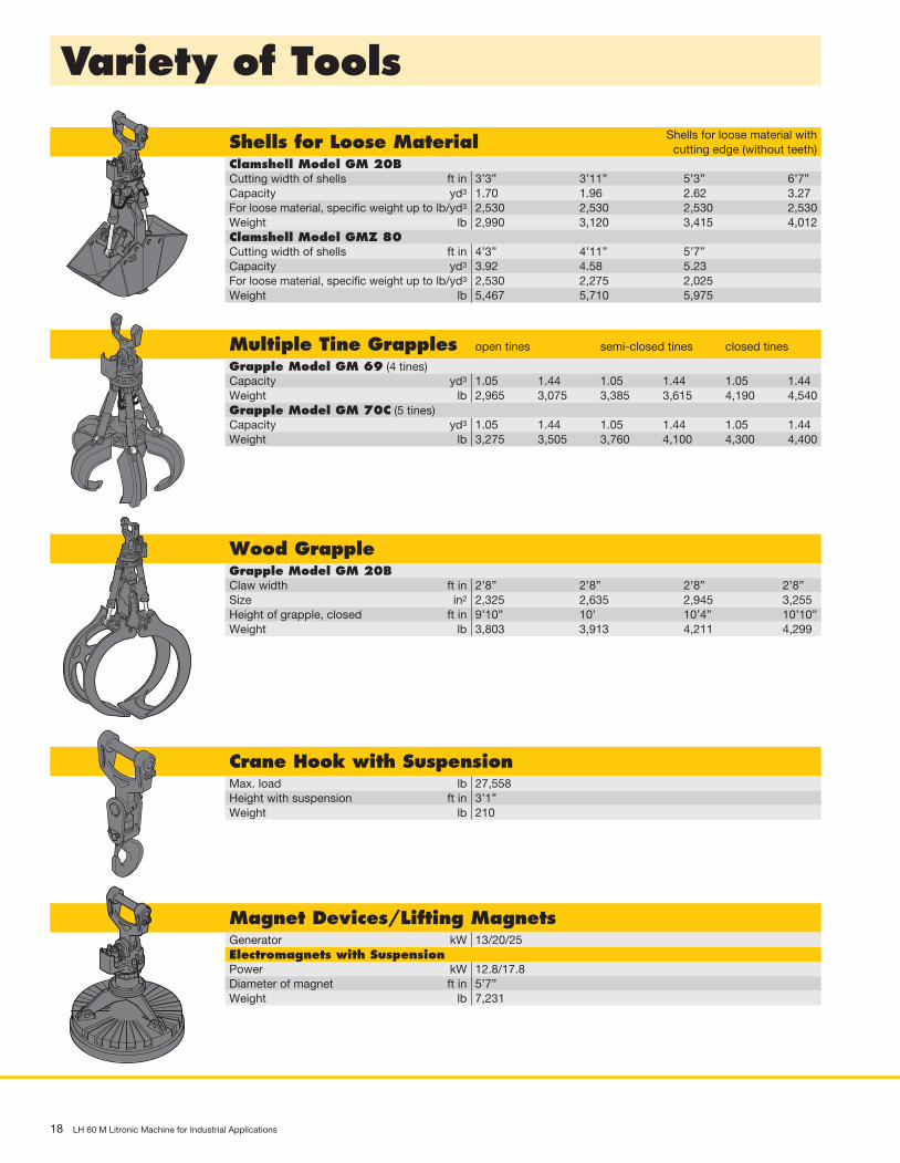
18 LH 60 M Litronic Machine for Industrial Applications
Variety of Tools
Shells for Loose Material Shells for loose material with cutting edge (without teeth)
Clamshell Model GM 20BCutting width of shells ft in 3’3” 3’11” 5’3” 6’7”Capacity yd3 1.70 1.96 2.62 3.27For loose material, specific weight up to lb/yd3 2,530 2,530 2,530 2,530Weight lb 2,990 3,120 3,415 4,012Clamshell Model GMZ 80Cutting width of shells ft in 4’3” 4’11” 5’7”Capacity yd3 3.92 4.58 5.23For loose material, specific weight up to lb/yd3 2,530 2,275 2,025Weight lb 5,467 5,710 5,975
Multiple Tine Grapples open tines semi-closed tines closed tines
Grapple Model GM 69 (4 tines)Capacity yd3 1.05 1.44 1.05 1.44 1.05 1.44Weight lb 2,965 3,075 3,385 3,615 4,190 4,540Grapple Model GM 70C (5 tines)Capacity yd3 1.05 1.44 1.05 1.44 1.05 1.44Weight lb 3,275 3,505 3,760 4,100 4,300 4,400
Wood GrappleGrapple Model GM 20BClaw width ft in 2’8” 2’8” 2’8” 2’8”Size in2 2,325 2,635 2,945 3,255Height of grapple, closed ft in 9’10” 10’ 10’4” 10’10”Weight lb 3,803 3,913 4,211 4,299
Crane Hook with SuspensionMax. load lb 27,558Height with suspension ft in 3’1”Weight lb 210
Magnet Devices/Lifting MagnetsGenerator kW 13/20/25Electromagnets with SuspensionPower kW 12.8/17.8Diameter of magnet ft in 5’7”Weight lb 7,231

LH 60 M Litronic Machine for Industrial Applications 19
B
B
A
A
System power
The energy recovery cylinder is a storage system which is independ-ent of the diesel engine. The system performance of material handling machines fitted with the ERC system is composed of the installed engine power and the energy recovery cylinder. When the equipment is raised, energy from the ERC system is supplied in addition to the power from the diesel engine.
1. Attachment fitting raised / Energy released
2. Lower attachment fitting / Store energy 4. Raise attachment fitting / Release energy
3. Attachment fitting lowered / Energy stored
Po
wer
[kW
]
Boom position
Engine powerERC performance
System performance
System power
Engine ERC
• fuel savings of up to 30 %
• lower running costs
• reduced pollutant and noise emissions
• increased overall power
ERC-System
ERC System – More performance, less consumption
Liebherr ERC-System
Lowering the equipment stores energy in the ERC system. This stored energy is then made available to the machine to provide additional engine power. When the equipment is raised the stored energy is released and is reflected in powerful, homogeneous operating cycles. The result is a clear saving on fuel – and, at the same time, even greater performance.
Efficiencyas standard
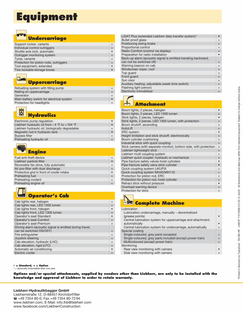
Equipment
• = Standard, + = Option* = optionally extendable after one year
Options and/or special attachments, supplied by vendors other than Liebherr, are only to be installed with the knowledge and approval of Liebherr in order to retain warranty. P
rinte
d in
Ger
man
y b
y Ty
pod
ruck
R
G-B
K-R
P
LHB
/VF
1121
2908
-0.5
-03.
14_e
nUS
A
ll ill
ustr
atio
ns a
nd d
ata
may
diff
er fr
om s
tand
ard
eq
uip
men
t. S
ubje
ct t
o ch
ange
with
out
notic
e.
Liebherr-Hydraulikbagger GmbH Liebherrstraße 12, D-88457 Kirchdorf/Iller +49 7354 80-0, Fax +49 7354 80-72 94 www.liebherr.com, E-Mail: [email protected] www.facebook.com/LiebherrConstruction
UndercarriageSupport rocker, variants +Individual control outriggers +Shuttle axle lock, automatic •Outrigger monitoring system +Tyres, variants +Protection for piston rods, outriggers +Tool equipment, extended •Two lockable storage boxes •
LiDAT Plus (extended Liebherr data transfer system) * •Bullet proof glass +Positioning swing brake +Proportional control +Radio Comfort (control via display) +Preparation for radio installation •Back-up alarm (acoustic signal is emitted traveling backward, can not be switched off) +Warning beacon on cab +Windscreen wiper, roof +Top guard +Front guard +Sun visor +Auxiliary heating, adjustable (week time switch) +Flashing light (xenon) +Electronic immobilizer +
Operator’s CabCab lights rear, halogen +Cab lights rear, LED 1300 lumen +Cab lights front, halogen •Cab lights front, LED 1300 lumen +Operator’s seat Standard •Operator’s seat Comfort +Operator’s seat Premium +Driving alarm (acoustic signal is emitted during travel, can be switched ON/OFF) +Fire extinguisher +Joystick steering +Cab elevation, hydraulic (LHC) +Cab elevation, rigid (LFC) +Automatic air conditioning •Electric cooler +
AttachmentBoom lights, 2 pieces, halogen •Boom lights, 2 pieces, LED 1300 lumen +Stick lights, 2 pieces, halogen •Stick lights, 2 pieces, LED 1300 lumen, with protection +Boom shutoff, ascending +AutoLift +ERC system •Height limitation and stick shutoff, electronically +Boom cylinder cushioning +Industrial stick with quick coupling +Stick camera (with separate monitor), bottom side, with protection +Liebherr lightweight stick +Liebherr multi coupling system +Liebherr quick coupler, hydraulic or mechanical +Pipe fracture safety valves hoist cylinders •Pipe fracture safety valve stick cylinder •Quick coupling system LIKUFIX +Quick coupling system MH40/MH110 +Protection for piston rod, ERC +Protection for piston rod, hoist cylinder +Retract stick without pressure •Overload warning device +Protection for stick +
UppercarriageRefuelling system with filling pump +Railing on uppercarriage +Generator +Main battery switch for electrical system •Protection for headlights +
HydraulicsElectronic pump regulation •Liebherr hydraulic oil from – 4 °F to + 104 °F •Liebherr hydraulic oil, biologically degradable +Magnetic rod in hydraulic tank •Bypass filter +Preheating hydraulic oil +
EngineFuel anti-theft device +Liebherr particle filter •Reversible fan drive, fully automatic +Air pre-filter with dust discharge +Protective grid in front of cooler intake •Preheating fuel +Preheating coolant +Preheating engine oil +
Complete MachineLubrication
Lubrication undercarriage, manually – decentralized (grease points) •Central lubrication system for uppercarriage and attachment, automatically •Central lubrication system for undercarriage, automatically +
Special coatingSingle-coloured, grey parts excepted +Single-coloured, grey parts included (except power train) +Multicoloured (except power train) +
MonitoringRear view monitoring with camera •Side view monitoring with camera +


![INDEX [] LG-1550 LIEBHERR LTM 1500 LIEBHERR LTM-1400 LIEBHERR LTM-1225 LIEBHERR LTM-1220 LIEBHERR ... Cranes_over100tons.pdf](https://static.fdocuments.us/doc/165x107/5b07232e7f8b9ae9628e08fa/index-lg-1550-liebherr-ltm-1500-liebherr-ltm-1400-liebherr-ltm-1225-liebherr.jpg)
