MACHINE DESIGN II MEC 3110
29
LECTURE - 13 ROLLING-ELEMENT BEARING PROBLEMS PROF. M. NAUSHAD ALAM MECHANICAL ENGINEERING DEPARTMENT A.M.U. ALIGARH MACHINE DESIGN II MEC 3110 k 8/21/2020 M. N. Alam / Mech. Engg. Dept. / A.M.U. Aligarh
Transcript of MACHINE DESIGN II MEC 3110

LECTURE - 13
ROLLING-ELEMENT BEARING PROBLEMS
P R O F. M . N A U S H A D A L A M
M E C H A N I C A L E N G I N E E R I N G D E P A R T M E N T
A . M . U . A L I G A R H
MACHINE DESIGN I I
MEC 3110
k
8/21/2020 M. N. Alam / Mech. Engg. Dept. / A.M.U. Aligarh

Problem-1
8/21/2020 M. N. Alam / Mech. Engg. Dept. / A.M.U. Aligarh
2
In a particular application, the radial load acting on a ball bearing is 5 kN and the
expected life for 90% of the bearings is 8000 h. Calculate the dynamic load carrying
capacity of the bearing, when the shaft rotates at 1450 rpm.
Solution:
Given Data:

Problem-2
8/21/2020 M. N. Alam / Mech. Engg. Dept. / A.M.U. Aligarh
3
A taper roller bearing has a dynamic load capacity of 26 kN. The desired life for 90%
of the bearings is 8000 h and the speed is 300 rpm. Calculate the equivalent radial load
that the bearing can carry.
Solution:
Given; C = 26 kN, L10h = 8000 h, n = 300 rpm

SELECTION OF BEARING LIFE
8/21/2020 M. N. Alam / Mech. Engg. Dept. / A.M.U. Aligarh
4
While selecting the proper size of a bearing, it is necessary to specify the expected life of the
bearing for the given application.
The information regarding the life expectancy is generally vague and values based on past
experience are used.
For all kinds of vehicles, the speed of rotation is not constant and the desired life is expressed in
terms of millions of revolutions. The recommended bearing life for wheel applications is given in
Table below.

Selection of Bearing Life
8/21/2020 M. N. Alam / Mech. Engg. Dept. / A.M.U. Aligarh
5
In the other applications, the speed of rotation is relatively constant and the desired life is
expressed in terms of hours of service.
LOAD FACTOR
8/21/2020 M. N. Alam / Mech. Engg. Dept. / A.M.U. Aligarh
6
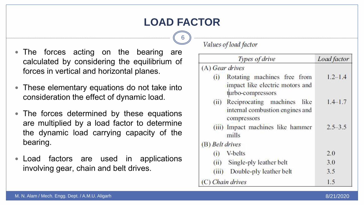
The forces acting on the bearing are
calculated by considering the equilibrium of
forces in vertical and horizontal planes.
These elementary equations do not take into
consideration the effect of dynamic load.
The forces determined by these equations
are multiplied by a load factor to determine
the dynamic load carrying capacity of the
bearing.
Load factors are used in applications
involving gear, chain and belt drives.

SELECTION OF BEARING
8/21/2020 M. N. Alam / Mech. Engg. Dept. / A.M.U. Aligarh
7
Selection of a bearing from the manufacturer’s catalogue
The basic procedure for the selection consists of the following steps:
(i) Calculate the radial and axial forces acting on the bearing and determine the
diameter of the shaft where the bearing is to be fitted.
(ii) Select the type of bearing for the given application.
(iii) Determine the values of X and Y, the radial and thrust factors, from the
catalogue. The values of X and Y factors for single-row deep groove ball
bearings are given in Table.
The values depend upon two ratios
where C0 is the static load capacity.

Selection of a bearing from the manufacturer’s catalogue
8/21/2020 M. N. Alam / Mech. Engg. Dept. / A.M.U. Aligarh
8
(iv) Calculate the equivalent dynamic load from the equation.
(v) Make a decision about the expected bearing life and express the life L10 in million revolutions.
(vi) Calculate the dynamic load capacity from the equation.
(vii) Check whether the selected bearing of series 60 has the required dynamic
capacity. If not, select the bearing of the next series and go back to Step (iii) and continue.
Ball bearings are thus selected by the trial and error procedure. The above procedure is also applicable to other types of bearings.

Table
8/21/2020 M. N. Alam / Mech. Engg. Dept. / A.M.U. Aligarh
9

PROBLEM-3
8/21/2020 M. N. Alam / Mech. Engg. Dept. / A.M.U. Aligarh
10
Select a single-row deep groove ball bearing, for a shaft that is 75 mm in diameter and
which rotates at 125 rpm. The bearing is subjected to a radial load of 21 kN and there is
no thrust load. The expected life of the bearing is 10 000 hours.
Solution
Given,
Fr = 21 000 N, Fa = 0 d = 75 mm
Type: single-row deep groove ball bearing
Step (iii) Since there is no axial load,
P = Fr = 21 000 N

Solution
8/21/2020 M. N. Alam / Mech. Engg. Dept. / A.M.U. Aligarh
11
Step (vi) It is observed from Table 15.5, that following bearings are available with 75mmbore diameter,

…
8/21/2020 M. N. Alam / Mech. Engg. Dept. / A.M.U. Aligarh
12

8/21/2020 M. N. Alam / Mech. Engg. Dept. / A.M.U. Aligarh
13

…
8/21/2020 M. N. Alam / Mech. Engg. Dept. / A.M.U. Aligarh
14
A rolling contact bearing is usually designated by three or four digits. The meaning of
these digits is as follows:
(i) The last two digits indicate the bore diameter of the bearing in mm (bore
diameter divided by 5). For example, XX07 indicates a bearing of 35 mm bore
diameter.
(ii) The third digit from the right indicates the series of the bearing. The numbers
used to indicate the series are as follows:
Extra light series –1 Light series – 2
Medium series – 3 Heavy series – 4
For example, X307 indicates a medium series bearing with a bore diameter of 35 mm.
(iii) The fourth digit and sometimes fifth digit from the right specifies the type of rolling
contact bearing. For example, the digit 6 indicates deep groove ball bearings

PROBLEM
8/21/2020 M. N. Alam / Mech. Engg. Dept. / A.M.U. Aligarh
15
A single-row deep groove ball bearing is subjected to a radial force of 8 kN and a thrust force of 3 kN. The shaft rotates at 1200 rpm. The expected life L10h of the bearing is 20 000 h. The minimum acceptable diameter of the shaft is 75 mm. Select a suitable ball bearing for this application
Solution
Given Fr = 8 kN, Fa = 3 kN, L10h = 20 000 hr
n = 1200 rpm d = 75 mm
Step I X and Y factors
When the bearing is subjected to radial as well as axial load, the values of X and Y factors are obtained from Table 15.4 by trial and error procedure. It is observed from Table 15.4, that values of X are constant and the values of Y vary only in case when
..
8/21/2020 M. N. Alam / Mech. Engg. Dept. / A.M.U. Aligarh
16
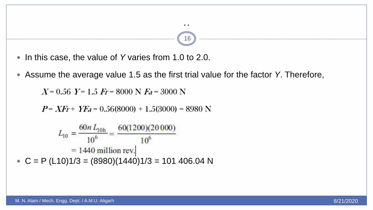
In this case, the value of Y varies from 1.0 to 2.0.
Assume the average value 1.5 as the first trial value for the factor Y. Therefore,
X = 0.56 Y = 1.5 Fr = 8000 N Fa = 3000 N
P = XFr + YFa = 0.56(8000) + 1.5(3000) = 8980 N
C = P (L10)1/3 = (8980)(1440)1/3 = 101 406.04 N
,,
8/21/2020 M. N. Alam / Mech. Engg. Dept. / A.M.U. Aligarh
17
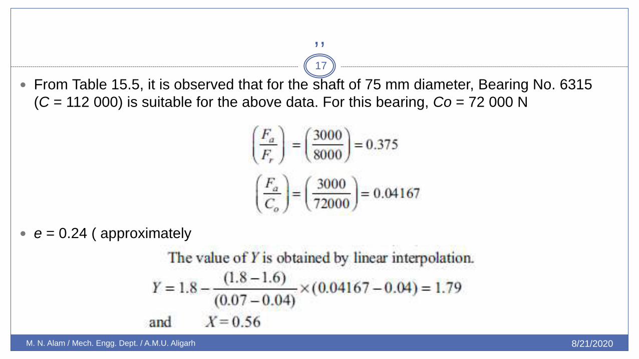
From Table 15.5, it is observed that for the shaft of 75 mm diameter, Bearing No. 6315
(C = 112 000) is suitable for the above data. For this bearing, Co = 72 000 N
e = 0.24 ( approximately
Problem
8/21/2020 M. N. Alam / Mech. Engg. Dept. / A.M.U. Aligarh
18
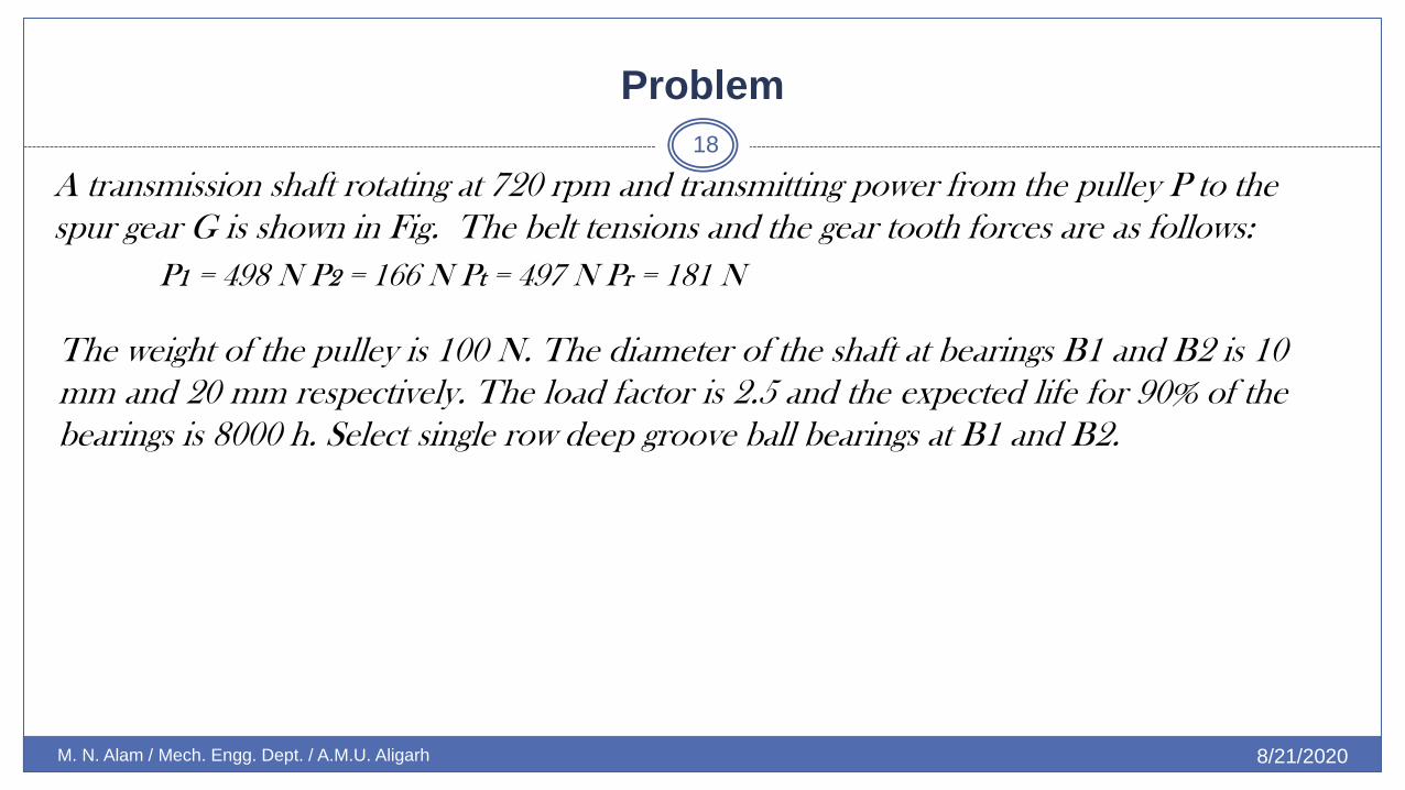
A transmission shaft rotating at 720 rpm and transmitting power from the pulley P to the
spur gear G is shown in Fig. The belt tensions and the gear tooth forces are as follows:
P1 = 498 N P2 = 166 N Pt = 497 N Pr = 181 N
The weight of the pulley is 100 N. The diameter of the shaft at bearings B1 and B2 is 10
mm and 20 mm respectively. The load factor is 2.5 and the expected life for 90% of the
bearings is 8000 h. Select single row deep groove ball bearings at B1 and B2.

Solution
8/21/2020 M. N. Alam / Mech. Engg. Dept. / A.M.U. Aligarh
19
Given : n = 720 rpm,
d1 = 10 mm,
d2 = 20 mm
L10h = 8000 h
load factor = 2.5
Step I Radial and axial forces
Considering forces acting on the shaft
in the vertical plane

Solution
8/21/2020 M. N. Alam / Mech. Engg. Dept. / A.M.U. Aligarh
20
Considering forces in the horizontal plane and
taking moments of forces about the bearing B1,
The reactions at the two bearings are given by,
The bearing reactions are in the radial direction.
There is no axial thrust on these bearings;
hence,
Solution
8/21/2020 M. N. Alam / Mech. Engg. Dept. / A.M.U. Aligarh
21
Step II Dynamic load capacities
Considering forces acting Considering the load factor
on the shaft

Solution
8/21/2020 M. N. Alam / Mech. Engg. Dept. / A.M.U. Aligarh
22
Step III Selection of bearings
From the Table, the following bearings are
available for 10 mm and 20 mm shaft
diameter;
Bearing Nos. 6000
and 6404
are suitable at B1 and B2 respectively.

PROBLEM
8/21/2020 M. N. Alam / Mech. Engg. Dept. / A.M.U. Aligarh
23
A shaft transmits 50 kW at 125 rpm from the gear G1 to the gear G2 and mounted on
Rolling Contact Bearings 579 two single-row deep groove ball bearings B1 and B2. The gear tooth
forces are
Pt1 = 15915 N Pr1 = 5793 N
Pt2 = 9549 N Pr2 = 3476 N
The diameter of the shaft at bearings B1 and B2 is 75 mm. The load factor is 1.4 and the
expected life for 90% of the bearings is 10000 h. Select suitable ball bearings.

Solution
8/21/2020 M. N. Alam / Mech. Engg. Dept. / A.M.U. Aligarh
24
Given
kW = 50
n = 125 rpm
d = 75 mm
L10h = 10 000 h
load factor = 1.4
Considering forces in the vertical plane and taking
moments about bearing B1,

…
8/21/2020 M. N. Alam / Mech. Engg. Dept. / A.M.U. Aligarh
25
Considering equilibrium of forces in the vertical plane
A similar procedure is repeated for calculating forces in the horizontal plane and the
reactions
The radial forces at the two bearings are given by
Since there is no axial thrust,

…
8/21/2020 M. N. Alam / Mech. Engg. Dept. / A.M.U. Aligarh
26
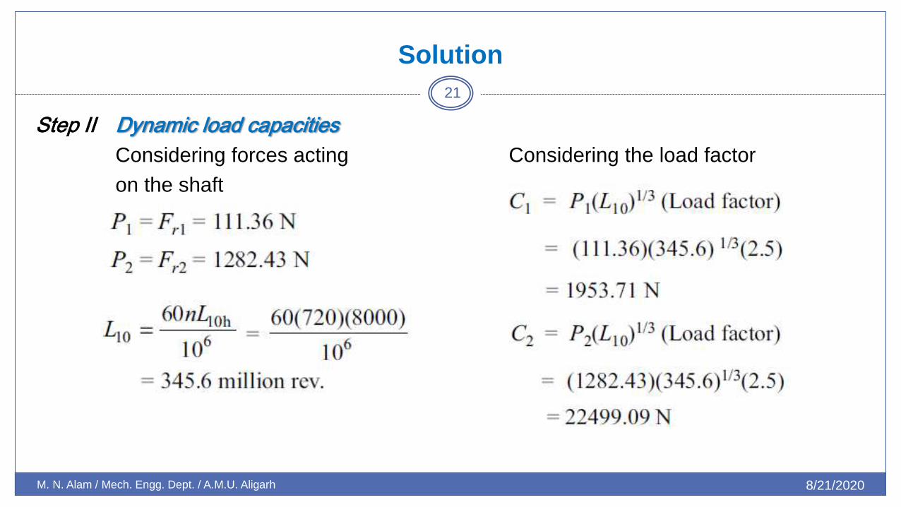
Step II Dynamic load capacities
Considering forces acting on the shaft
in the vertical plane
Considering the load factor and using the dynamic load capacities are given by,
…
8/21/2020 M. N. Alam / Mech. Engg. Dept. / A.M.U. Aligarh
27
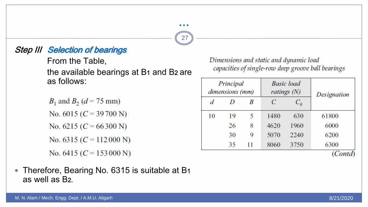
Step III Selection of bearings
From the Table,
the available bearings at B1 and B2 are as follows:
Therefore, Bearing No. 6315 is suitable at B1 as well as B2.

…
8/21/2020 M. N. Alam / Mech. Engg. Dept. / A.M.U. Aligarh
28
Step IV Bearing life (L50)
It can be proved that the life (L50), which 50% of the bearings will complete or
exceed, is approximately five times the life L10 which 90% of the bearings will
complete or exceed.
Therefore,.

.
8/21/2020 M. N. Alam / Mech. Engg. Dept. / A.M.U. Aligarh
29
End of Lecture