Machinability of Engineering Materials - Springer · Machinability of Engineering Materials Hongyu...
34
Machinability of Engineering Materials Hongyu Zheng* and Kui Liu Institute of Manufacturing Technology, Singapore Abstract There are thousands of materials available for engineering applications. Machinability is an indica- tor of one engineering material how easy or difficult to be machined using a cutting tool to achieve an acceptable surface finish, which could be considered as a material property. Engineers are often challenged to find ways to improve machinability without harming material performance, which are much focused on the machining efficiency and productivity. However, unlike most material properties, machinability cannot be simplified into a unique work material property, but rather considering as a resultant property of the machining system which is mainly affected by work material’ s physical properties, heat treatment processes, and work-hardening behavior, as well as cutting tool materials, tool geometry, machining operation type, cutting conditions, and cutting fluids. When assessing a material machinability, all other aspects of the machining system must be considered concurrently. An understanding of the interactions between tool and work materials at the tool–work interface would benefit to machining behavior and machinability. Tool material and cutting speed perhaps are the two most important parameters for engineering material machinability assessments. Materials with good machinability require little power to cut, can be cut quickly, easily obtain a good surface finish, and do not wear the cutting tool fast. Engineering materials could be developed with improved machinability or more uniform machinability through microstructure modification and chemical components adjustment. Advance developed tool materials with high thermal hardness and wear resistance would improve the material machinability. Introduction Engineering Materials There are thousands of materials available for engineering applications. Based on the atomic bonding forces of a particular material, all engineering materials can be grouped into four classes: metallic, ceramic, polymeric, and composite which is created by a combination of different materials. Within each of four classes, materials can be further organized into groups based on their chemical composition or certain physical or mechanical properties. Below is a list of four general groups of materials and their distinctive properties. (A) Metals and alloys – inorganic materials compounded one or more metallic elements, including ferrous metals and alloys (iron, carbon steel, stainless steel, tool steel, and steel alloy) and nonferrous metals and alloys (aluminum, copper, brass, magnesium, nickel, titanium, and superalloys): *Email: [email protected] Handbook of Manufacturing Engineering and Technology DOI 10.1007/978-1-4471-4976-7_2-1 # Springer-Verlag London 2013 Page 1 of 34
Transcript of Machinability of Engineering Materials - Springer · Machinability of Engineering Materials Hongyu...

Machinability of Engineering Materials
Hongyu Zheng* and Kui LiuInstitute of Manufacturing Technology, Singapore
Abstract
There are thousands of materials available for engineering applications. Machinability is an indica-tor of one engineering material how easy or difficult to be machined using a cutting tool to achieve anacceptable surface finish, which could be considered as a material property. Engineers are oftenchallenged to find ways to improve machinability without harming material performance, which aremuch focused on the machining efficiency and productivity. However, unlike most materialproperties, machinability cannot be simplified into a unique work material property, but ratherconsidering as a resultant property of the machining system which is mainly affected by workmaterial’s physical properties, heat treatment processes, and work-hardening behavior, as well ascutting tool materials, tool geometry, machining operation type, cutting conditions, and cuttingfluids. When assessing a material machinability, all other aspects of the machining system mustbe considered concurrently. An understanding of the interactions between tool and work materials atthe tool–work interface would benefit to machining behavior and machinability. Tool materialand cutting speed perhaps are the two most important parameters for engineering materialmachinability assessments. Materials with good machinability require little power to cut, can becut quickly, easily obtain a good surface finish, and do not wear the cutting tool fast. Engineeringmaterials could be developed with improved machinability or more uniform machinabilitythrough microstructure modification and chemical components adjustment. Advance developedtool materials with high thermal hardness and wear resistance would improve the materialmachinability.
Introduction
Engineering MaterialsThere are thousands of materials available for engineering applications. Based on the atomicbonding forces of a particular material, all engineering materials can be grouped into four classes:metallic, ceramic, polymeric, and composite which is created by a combination of differentmaterials. Within each of four classes, materials can be further organized into groups based ontheir chemical composition or certain physical or mechanical properties. Below is a list of fourgeneral groups of materials and their distinctive properties.
(A) Metals and alloys – inorganic materials compounded one or more metallic elements, includingferrous metals and alloys (iron, carbon steel, stainless steel, tool steel, and steel alloy) andnonferrous metals and alloys (aluminum, copper, brass, magnesium, nickel, titanium, andsuperalloys):
*Email: [email protected]
Handbook of Manufacturing Engineering and TechnologyDOI 10.1007/978-1-4471-4976-7_2-1# Springer-Verlag London 2013
Page 1 of 34
• Usually having crystalline structure• High thermal and electrical conductivity• High strength and elastic modulus• Good ductility and toughness• Strengthened by alloying and heat treatment• Corrosion resistant
(B) Ceramics and glasses – inorganic materials consisted of both metallic and nonmetallic elementsbonded together, including glass, carbide, glass ceramic, and graphite:
• High melting point• High chemical stability• High hardness and thermal strength• Brittleness• Low electrical conductivity
(C) Polymers – organic materials consisted of long molecular chains or networks containing carbon,including thermoplastic, thermosetting plastic, and elastomer:
• Low density and low rigidity• Low electrical conductivity• Good strength-to-weight ratio• Corrosion resistance, but does not apply to high temperature• Good compatibility with human tissue
(D) Composites – consisted of two or more above distinct materials together, including metal-matrix composite, ceramic matrix composite, and fiber reinforcement composite:
• Consisting a matrix and a reinforcement• Combining the best properties of each component material
Definition of MachinabilityThe term “machinability” is a property of a material which governs the ease or difficulty with whichthe material can be machined, achieving an acceptable surface finish using a cutting tool. Materialswith good machinability require little power to cut, can be cut quickly, easily obtain a good surfacefinish, and do not wear the cutting tool fast. Such materials are said to be free machining. Thus, allengineering materials machined may be classified as (Shaw 1983):
1. Easy-machining materials (aluminum and copper alloys)2. Ordinary wrought steels and cast irons3. Difficult-to-machine materials
Manufacturing and production engineers are often challenged to find ways to improve machin-ability without harming material performance, which are much focused on the machining efficiencyand productivity. However, unlike most material properties, machinability cannot be simplified intoa unique work material property which is not a commonly accepted parameter used for its
Handbook of Manufacturing Engineering and TechnologyDOI 10.1007/978-1-4471-4976-7_2-1# Springer-Verlag London 2013
Page 2 of 34

measurement of machining performance, but rather considering as a resultant property of themachining system which is mainly affected by work material’s physical properties such as micro-structure, grain size, heat treatment, chemical composition, fabrication, hardness, yield strength,tensile strength, Young’s modulus, thermal conductivity, thermal expansion, and work hardening.Other factors also affecting material machinability include cutting tool materials, tool geometry,machining operation type, cutting conditions, and cutting fluids, as well as machine tool, fixture,and jig.
Machinability CriteriaThere are many factors affecting material machinability, but no widely accepted way to quantifyit. The basic machinability of a material is a function of its (Shaw 1983):
• Chemistry• Structure• Compatibility with tool materials
The basic machining characteristics of all engineering materials are quite different due to thedifferences in their chemical and physical properties. Such a wide variety of engineering materialswill also have different machinability depending uponmachining conditions and tool materials used.As the machinability is more like a resultant property of the machining system, to assess onematerial’s machining performance, i.e., machinability, may utilize one or more of the followingcriteria (Trent and Wright 2000):
1. Tool life – is the measurement of how long a tool lasts when cutting a material. The Taylorequation for tool life expectancy provides a good approximation:
VcTn ¼ C (1)
where Vc is cutting speed,T is tool life, andn and C are constants found by experimentation or published data; they are properties of tool
material, workpiece, and feed rate.
2. Martial removal rate (MMR) – is the volume of material removed by the cutting tool per unit time.For milling process, the material removal rate of the process can be obtained by
RMR ¼ nfd (2)
where RMR is material removal rate,v is cutting speed,f is feed rate, andd is depth of cut.
3. Machined surface finish – also known as surface texture, is a characteristic of a surface including,surface roughness, and waviness. One of the most effective surface roughness measurement,commonly adopted in general engineering practice, is known as arithmetic mean value Ra, anarithmetic average of the absolute values as following:
Handbook of Manufacturing Engineering and TechnologyDOI 10.1007/978-1-4471-4976-7_2-1# Springer-Verlag London 2013
Page 3 of 34

Ra ¼ 1
n
Xnyij j (3)
where Ra is arithmetic mean surface roughness.It gives a good general description of the height variations in the machined surfaces.The
surface profile contains n equally spaced points along the trace, and is the vertical distance fromthe mean line to the point. Height is assumed to be positive above the mean line, and negativebelow the mean line.
4. Cutting forces – required for a tool to cut through a material directly related to the powerconsumed. Therefore, tool forces are often given in units of specific cutting energy, Ps, i.e.,energy required to remove unit volume of material:
Ps ¼ F=fd (4)
where F is cutting force.5. Cutting power – is the power consumed by the machine tool during machining operations to
remove the unwanted material from the workpiece material in the form of chips, which can beexpressed as
Pm ¼ Fn (5)
where Pm is cutting power.6. Chip formation – chips formed and flowed along rake face around the cutting tool and chip shapes
influenced by work materials, machining operation type, cutting tool geometry, and cuttingconditions. Normally, there are three basic types of chip formed during machining processes:continuous, discontinuous, and continuous with built-up edge (BUE). For some extreme cases,types of chips formed may change from continuous to continuous with BUE and further todiscontinuous even cutting of the same work material with the same cutting tool just by changingits cutting parameters.
A material may have good machinability by one criterion, but poor by another. Also, relativemachinability may change when a different type of machining operation is being carried out, forexample, turning versus milling, or the tool material used being changed. Due to many factorsinvolved, it is best to state the comparison when two materials are compared to theirmachinability.
Material Property Effects on Machinability
The best machinability can be achieved in a material if there is:
• Not too high ductility• No high work (strain) hardening• Not too much abrasiveness
Handbook of Manufacturing Engineering and TechnologyDOI 10.1007/978-1-4471-4976-7_2-1# Springer-Verlag London 2013
Page 4 of 34

It is not easy to define the material machinability without the help of the original material’sproperties. But certain trends can be found for certain materials.
HardnessHardness is closely related to strength. It is the ability of a material to resist a localized deformationfrom indentation, scratching, penetration bending, abrasion, and wear. Alloying techniques and heattreatment would help to achieve high resistance to the localized deformation, i.e., high hardnessachieved after alloying or heat treatment. It is measured on special hardness testers by measuring theresistance of the material against penetration of an indent or of special shape under a given load.Hardness measurements are widely used for material quality control because they are fast andconsidered to be nondestructive tests. The different scales of hardness are Brinell hardness,Rockwell hardness, Vickers hardness, etc. Hardness can be an indicator of material machinability,but hardness alone is not consistent as a measure of material machinability.
The material’s machinability varies with its microstructure and hardness (Finn 1989). A workmaterial having a low hardness and low work-hardening rate produces small cutting forces and lowcontact pressure at the tool–chip interface, consequently causing a low temperature rising at thecutting region, hence, shows a good machinability. Low hardness values make a material easier tomachine. However, low hardness is a disadvantage if it is associated with high ductility.
Apparently, a material is chosen for a particular application primarily due to its properties andfunctions, and generally, its machining performance is becoming a secondary factor in this selection.Hardness is changed in accordance with its microstructure. Therefore, control of work materialmicrostructure is particularly important as it is one property which can be influenced by the materialmanufacturer, to some extent. Hard particles like carbides and nitrides are undesirable for materialsas they are the cause to a faster abrasive tool wear. If a slight degradation of material propertieswould not much affecting on its application, choosing an easy-to-machine material will benefit to thereducing of machining cost.
Yield StrengthStress is a resistance against the internal force acting within a deformable object. Quantitatively, it isa measure of the average force per unit area of a plane within the object on which internal forces act.These internal forces arise as a reaction to external loads applied to the object. Normal stress s is ona plane perpendicular to the longitudinal axis of the object, which can be calculated using thefollowing equation:
s ¼ P
A(6)
where P is external applied load andA is original cross-sectional area.A strain is a normalized measurement of the deformation representing the displacement between
particles in the object relative to a reference length. Normal strain e in the longitudinal direction is thetotal deformation divided by the original length of the object, which can be calculated using thefollowing equation:
Handbook of Manufacturing Engineering and TechnologyDOI 10.1007/978-1-4471-4976-7_2-1# Springer-Verlag London 2013
Page 5 of 34
e ¼ dL
(7)
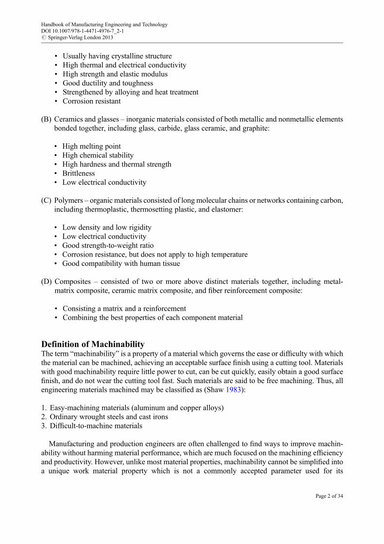
where d is change in the object’s length andL is original object length.As shown in Fig. 1, the stress s is shown as a function of strain e and the initial portion of the
stress–strain curve for the most materials used in engineering structures is a straight line. That is, forstress–strain curve straight line portion, the stress s is directly proportional to the strain e, of whichthis relationship is known as Hooke’s law in terms of continuummechanics and was first recorded byRobert Hooke, an English mathematician, in 1678. Therefore, for an object subjected to a uniaxialload, its strain e is linearly proportional to its tensile stress s by a constant factor E; hence,
s ¼ Ee (8)
where E is elastic modulus.Hooke’s law only holds for some materials under certain loading conditions, which is only valid
for it throughout its elastic range, i.e., for stresses below yield strength.Yield stress is an indicator of the stress level where the material begins to deform plastically. This
stress level point is called as yield point where some fraction of the deformation will be permanentand nonreversible, and the material no longer returns to its original shape and size after the applied
Rupture
a b
EE
Yield
0 0.2%ε ε
σY
σσ
σU
Strain-hardening Necking
Fig. 1 Stress–strain curve showing a typical yield behavior for engineering materials. (a) Ferrous alloys. (b) Nonferrousalloys
Opening Mode
ab c
Sliding Mode Tearing Mode
Fig. 2 Three possible modes of crack extension in materials
Handbook of Manufacturing Engineering and TechnologyDOI 10.1007/978-1-4471-4976-7_2-1# Springer-Verlag London 2013
Page 6 of 34
stress release. However, not all material has a well-defined yield point. In the absence of a distinctyield point, a 0.2 % offset is used to obtain an approximate yield point. Figure 1 is a stress–straincurve showing typical yield behavior for nonferrous alloys: (a) ferrous alloys and (b) nonferrousalloys.
In general, material hardness and yield strength are related. A material with high yield strengthrequires a high level of force to initiate chip formation in a machining process. Materials withrelatively high strengths will be more difficult to machine and will reduce tool life. The same ashardness, a work material having low yield strength produces small cutting forces and low contactpressure at the tool–chip interface, consequently causing a low temperature rising at the cuttingregion, hence, shows a good machinability too.
Fracture ToughnessFracture mechanics is one field of mechanics concerned with the study of crack propagation inmaterials, which was developed during World War I by an English aeronautical engineer,A.A. Griffith, to explain the failure of brittle materials. Fracture is a separation of an object or amaterial into two, or more, pieces under the action of stress. Rather than focusing on the crack-tipstresses directly, Griffith employed an energy-balance approach that has become one of the mostfamous developments in material science, which can be used to calculate the driving force on a crackand characterize the material’s resistance to fracture.
Fracture toughness is one of the most important material properties for all actually designedapplications, which is an indicator of the stress amount required to propagate preexisting defects asthere is no perfect material in the nature. All materials more or less contain some flaws which mayhave appeared as cracks, voids, metallurgical impurity, twins, segregations, dislocations, disconti-nuities, or some combination thereof.
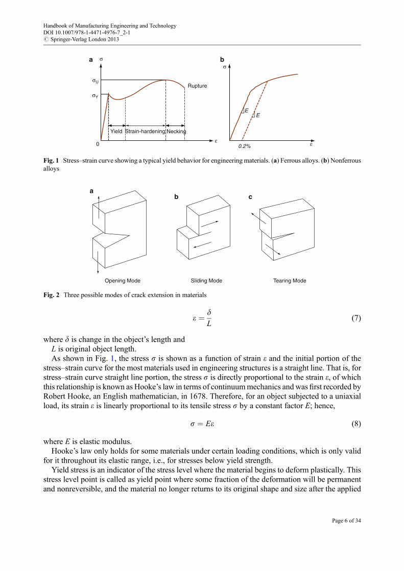
It has been shown that the two most important defects affecting the material failure are cracks anddislocations (Ewalds and Wanhill 1986). Usually, there are three possible modes of crack propaga-tion generally identified by the subscripts I, II, and III as shown in Fig. 2: mode I also called theopening mode, mode II usually called the sliding mode, and mode III also referred to as the tearingmode. In practice, among these three modes, the most applicable is the opening mode (mode I).Crack propagation in materials has been the subject of many researches in the field of linear elasticfracture mechanics and fatigue being well documented.
Irwin found that if the size of the plastic zone around a crack is small compared to the size of thecrack, the energy required to grow the crack will not be critically dependent on the state of stress atthe crack tip. He showed that for an opening mode crack (mode I), the strain energy release rateG forcrack growth and the stress intensity factor KI are relevant, which can be expressed using thefollowing stress field equations (Irwin 1957):
G ¼ GI ¼K2
I
Efor planestress
1� n2ð ÞK2I
Efor planestrain
8><>: (9)
where G is strain energy release rate or energy dissipation,GI is strain energy release rate for a mode I crack (opening mode),n is Poisson’s ratio, andKI is stress intensity factor in mode I.
Handbook of Manufacturing Engineering and TechnologyDOI 10.1007/978-1-4471-4976-7_2-1# Springer-Verlag London 2013
Page 7 of 34
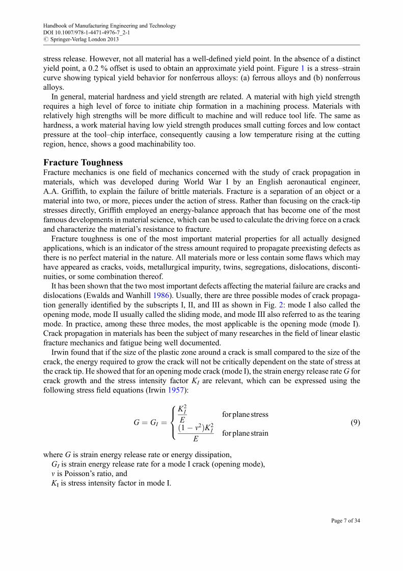
An internal through crack of length 2a is situated in a plate of finite width W and is subjected toa stress s at the boundary as shown in Fig. 3. The stress intensity factor KI is expressed as
KI ¼ Ysffiffiffiffiffiffipa
p(10)
where Y is a geometric factor anda is half crack length.Irwin also showed that the strain energy release rate of a planar crack in a linear elastic object can
be expressed in terms of the mode I, mode II (sliding mode), and mode III (tearing mode) stressintensity factors for the most general loading conditions.
As a property parameter of work materials, fracture toughness KC expresses the ability ofa material to resist the growth of a preexisting crack or flaw. The stresses at the tip of a crack aremuch larger than that in the uncracked materials. It is widely accepted that the stress intensity factorKI and fracture toughness KC largely affect crack propagations for materials (Kendall 1976). Thefracture toughness KC is expressed as
KC ¼ffiffiffiffiffiffiffiffiffiffiEGC
pfor planestressffiffiffiffiffiffiffiffiffiffiffiffiffi
EGC
1� n2
rfor planestrain
8<: (11)
where GC is critical energy release rate.If GI � GC, this is the criterion for which the crack will begin to propagate. Irwin modified
Griffith’s solids theory by using stress intensity factor KI replacing strain energy release rate GI andfracture toughness KC replacing surface weakness energy GC. Thus, when the stress intensity factorKI reaches a critical level of fracture toughness KC, i.e., KI � KC, the crack propagates and thenfracture occurs. Low fracture toughness contributes to easy crack propagation which results inreduction in the difficulty of producing broken chips. Hence, a low fracture toughness value makesa material easier to machine, showing a good machinability.
W
2a
q
s
s
Fig. 3 A plate of finite width subjected to uniform stress
Handbook of Manufacturing Engineering and TechnologyDOI 10.1007/978-1-4471-4976-7_2-1# Springer-Verlag London 2013
Page 8 of 34

Temperature Effects on MachinabilityThe power consumed in metal cutting is largely converted into heat around the cutting region. Hightemperatures are generated in the region of the cutting edge, which have a controlling influence onthe rate of tool wear and on the friction between the chip and tool (Boothroyd and Knight 1989).Temperature rise at the tool–work interface, varied with the composition of the work material, isdirectly affecting the cutting tool performance and significantly influences in limiting the rates ofmetal removal when cutting iron, steel, and other metals and alloys of high melting point. Temper-ature distribution at the tool–work interface was determined by changes in microhardness ormicrostructure in the heat-affected regions of work material.
During the orthogonal cutting of mild steel, the mean share zone temperature ys increases slightlywith increasing cutting speed and then tends to become constant. Since the temperature rise (ym) atthe tool rake owning to friction heat in the secondary deformation zone increases rapidly with theincreasing cutting speed, as a result, the maximum tool–work interface temperature (ym + ys)increases rapidly with the increasing cutting speed too (Boothroyd and Knight 1989). For example,the maximum tool–work interface temperature can reach as high as 1,000 �C when rough cutting ofsteel.
Tensile strength
Yieldstrength
Ductility
Temperature
Str
engt
h an
d D
uctil
ity
Fig. 4 Effect of temperature on material’s strength and ductility
Ceramic
High-alloy steel
High Csteel
Low C steel
Temperature, °C
Har
dnes
s
250 500
Fig. 5 Effect of temperature on material’s hardness
Handbook of Manufacturing Engineering and TechnologyDOI 10.1007/978-1-4471-4976-7_2-1# Springer-Verlag London 2013
Page 9 of 34

The high cutting temperature has a controlling influence on the work material mechanicalproperties as shown in Figs. 4 and 5. Figure 4 shows the effect of temperature on material’s strengthand ductility, and Fig. 5 shows the effect of temperature on the material’s hardness of differentengineering materials. Normally, most material tensile strength and yield strength will decrease withthe increasing temperature. For example, yield stress (YS) and ultimate tensile strength (UTS) ofsteel with 75 % ferrite, 15 % bainite, and 10 % retained austenite in volume decrease with anincreasing temperature. There exists a temperature region (120–400 �C) where a reduction ofstrength with increasing temperature is retarded or even slightly increased (Akbarpour 2007).
Ductility or elongation of most engineering materials will increase with the increasing tempera-ture. But increasing temperature will cause material hardness decreasing. Experimental results oftensile stress–strain curves obtained at temperatures of 260 �C and 480 �C for aluminum alloy 7000T4 applying a constant strain rate of 10�3 s�1 showed that the lower temperature specimenunderwent a moderately ductile failure with regions of both strain hardening and necking beforethe final sudden fracture, of which elastic modulus is 63 GPa, 0.2 % yield strength is 180 MPa, andultimate strength is 233 MPa. The higher temperature specimen experienced a highly ductile failurewith no sudden fracture, of which elastic modulus is 37 GPa, 0.2 % yield strength is 68 MPa, andultimate strength is 73 MPa (Codrington et al. 2009).
Figure 6 shows the typical effects of temperature on stress and strain for aluminum alloy 7075-T6:(a) strain obtained under three constant stresses heated rapidly at widely different temperature ratesand (b) stress–strain curve at three different temperatures with a constant strain rate. The slantportions of the curves give mainly the effects of thermal expansion. The sharp downward turn at theright of each curve gives the effects of viscosity.
Overall, when machining of whatever materials like metals, polymers, composites, or ceramics,there always is accompanying with a temperature rising in the cutting region. For example, whenrough cutting mild steel, the temperature rising in the cutting region can reach as high as more than1,000 �C. Definitely, such high temperature rising will change the work material mechanicalproperties such as microhardness, tensile strength, yield strength, ultimate tensile strength, ductility,and strain–stress status and frequently, material microstructure changing also happens. As a result,work material machinability will be changed accordingly, which would be a compound result of allkinds of effects including work material mechanical and thermal properties, microstructure, as wellas cutting tool thermal behavior.
Figure 7 shows a schematic diagram of suitable cutting speed including normal machining andhigh-speed machining for different work materials, which indicates the differences of machinabilityfor different work materials from the cutting speed aspect. For example, cutting with a speed of200 m/min is considered as a normal machining for fiber-reinforced plastics, aluminum, bronze, and
Strain Strain
T3
T3σ3
σ3
σ2
σ2
σ1
σ1
T2
T2
T1
T1
Tem
pera
ture
Str
ess
Fig. 6 Effects of temperature on material stress and strain
Handbook of Manufacturing Engineering and TechnologyDOI 10.1007/978-1-4471-4976-7_2-1# Springer-Verlag London 2013
Page 10 of 34
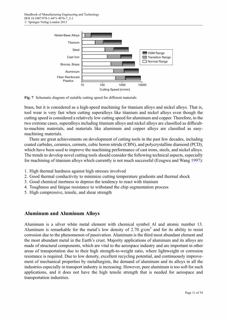
brass, but it is considered as a high-speed machining for titanium alloys and nickel alloys. That is,tool wear is very fast when cutting superalloys like titanium and nickel alloys even though thecutting speed is considered a relatively low cutting speed for aluminum and copper. Therefore, to thetwo extreme cases, superalloys including titanium alloys and nickel alloys are classified as difficult-to-machine materials, and materials like aluminum and copper alloys are classified as easy-machining materials.
There are great achievements on development of cutting tools in the past few decades, includingcoated carbides, ceramics, cermets, cubic boron nitride (CBN), and polycrystalline diamond (PCD),which have been used to improve the machining performance of cast irons, steels, and nickel alloys.The trends to develop novel cutting tools should consider the following technical aspects, especiallyfor machining of titanium alloys which currently is not much successful (Ezugwu and Wang 1997):
1. High thermal hardness against high stresses involved2. Good thermal conductivity to minimize cutting temperature gradients and thermal shock3. Good chemical inertness to depress the tendency to react with titanium4. Toughness and fatigue resistance to withstand the chip segmentation process5. High compressive, tensile, and shear strength
Aluminum and Aluminum Alloys
Aluminum is a silver white metal element with chemical symbol Al and atomic number 13.Aluminum is remarkable for the metal’s low density of 2.70 g/cm3 and for its ability to resistcorrosion due to the phenomenon of passivation. Aluminum is the third most abundant element andthe most abundant metal in the Earth’s crust. Majority applications of aluminum and its alloys aremade of structural components, which are vital to the aerospace industry and are important in otherareas of transportation due to their high strength-to-weight ratio, where lightweight or corrosionresistance is required. Due to low density, excellent recycling potential, and continuously improve-ment of mechanical properties by metallurgists, the demand of aluminum and its alloys in all theindustries especially in transport industry is increasing. However, pure aluminum is too soft for suchapplications, and it does not have the high tensile strength that is needed for aerospace andtransportation industries.
Fiber ReinforcedPlastics
Nickel-Base Alloys
Titanium
Steel
Cast Iron
Bronze, Brass
Aluminium
10 100 1000
Cutting Speed [m/min]
10000
HSM RangeTransition RangeNormal Range
Fig. 7 Schematic diagram of suitable cutting speed for different materials
Handbook of Manufacturing Engineering and TechnologyDOI 10.1007/978-1-4471-4976-7_2-1# Springer-Verlag London 2013
Page 11 of 34

Generally, the microconstituents present in aluminum alloys significantly influence the machiningcharacteristics. Nonabrasive constituents have a beneficial effect while insoluble abrasive constit-uents demonstrate a detrimental effect on tool life and machined surface quality. In fact, aluminumand aluminum alloys are considered as the family of materials offering the highest levels ofmachinability, as compared to other families of lightweight metals such as titanium and magnesiumalloys. In general, they belong to the most machinable materials in small-to-medium volumeproduction and mass production, which can be machined relatively easily.
As the melting temperature of aluminum (around 659 �C) and aluminum alloys is relatively low,consequently, the machining temperatures are generally low and never being high enough to damagethe cutting tools’microstructure such as high-speed steel tools and carbide tools. High cutting speedcan be used up to 600 m/min when carbide tools are being used and 300 m/min for high-speed steeltools. Cutting speed can be achieved as high as 5,000 m/min when using polycrystalline diamond(PCD) tools. Tool wear occurs generally in the form of flank wear when machining of aluminum andaluminum alloys. Good tool life can be obtained as long as 20 km when PCD or single crystallinediamond tools being used.
Pure AluminumFor commercial pure aluminum like many other pure metals, in spite of the lower share strength, thecutting forces are generated higher than those for aluminum alloys particularly at low cutting speedsdue to a very strong adhesion between the cutting tool and work material. The contact length on therake face tool–chip interface is very long, and no built-up edge (BUE) is present when machining ofcommercial pure aluminum. Long and ductile chips are formed regardless of the cutting toolgeometry used. High tendency of aluminum to adhere to cutting tools produces a high risk leadingto tool breakage during machining of commercial pure aluminum.
As the chips formed during machining of commercial pure aluminum are continuous, strong, andnot readily broken, it always clogs the flutes and spaces between teeth or accumulates and coils at thetool tip for single-point cutting. Therefore, the cutting tool needs to be sharp and have large positiverake angle with a chip breaker, and sometimes, specially designed cutting tools are required forcutting of aluminum.
Aluminum AlloysAluminum alloys are the alloys in which aluminum (Al) is the predominant elements. Typically, thetechnically alloying elements used for aluminum alloys are silicon, magnesium, manganese, zinc,and copper, targeting to improve fluidity, strength, ductility, castability, work hardening,etc. Aluminum alloys can be broadly categorized as the cast alloys and wrought alloys. Wroughtaluminum alloys are generally divided into the heat-treatable and non-heat-treatable groups.Wrought alloys account for about 85 % of aluminum use and are mainly made for the formingproducts, for example, rolled plates, foils, and extrusions. The most important cast alloys are Al–Sialloys, where the high levels of silicon (4.0–13 %) contribute to give good casting characteristics.
It is well known that chemical composition, structural defects, and alloying elements havesignificant effects on the machinability of aluminum alloys. High levels of magnesium(Mg) increase the cutting forces while maintaining the same level of hardness, and a low percentageof copper (Cu) in aluminum alloys decreases the cutting force (Tash et al. 2006). Alloys containingmore than 10 % Si are the most difficult to machine because hard particles of free silicon cause rapidtool wear. The presence of hard silicon particles in the alloys decreases machinability due toaccelerated abrasive wear of carbide tools and chipping of PCD tools, which typically are limitedto low cutting speeds both for carbide and PCD tools. When dry cutting aluminum alloys, the major
Handbook of Manufacturing Engineering and TechnologyDOI 10.1007/978-1-4471-4976-7_2-1# Springer-Verlag London 2013
Page 12 of 34
problems encountered are the BUE generated at low cutting speeds and sticking at high cuttingspeeds, hence, the need for special tool geometries. Different heat treatment methods can be used toimprove the machinability of aluminum alloys, which increase hardness and reduce the built-upedge (BUE) tendency during machining processes. Heat treatment of Al 6061, especially aging,influences the cutting forces only at low cutting speeds, but the influence is negligible at high cuttingspeeds because of the low temperature rising found in the cutting region.
Copper, Brass, and Copper Alloys
Copper is a reddish orange color metal element with chemical symbol Cu and atomic number29, which is a comparatively heavy metal with a density of 8.98 g/cm3. It is soft and malleable anda highly ductile metal with a face-centered cubic structure, but it has a high melting point of1,083 �C. Copper is one of the earliest metals known by human and have been used for thousandsof years. The attractive properties which made copper very wide applications are good corrosionresistance, attractive color, excellent workability, and the best electrical and thermal conductivity ofany commercially available metals. Today, more than 50 % of the copper produced is used inelectrical and electronic applications.
Copper alloys are metal alloys that have copper as their principal component. Typically, the mainalloying elements used for copper alloys are zinc, tin, aluminum, silicon, and nickel. There are asmany as 400 different copper and copper alloys loosely grouped into the categories: copper, brasses,bronzes, nickel copper, copper–nickel–zinc (nickel silver), leaded copper, and special alloys. Table 1lists the principal alloying element for most common types used in modern industry.
Copper and Copper AlloysPure copper is ductile and weak but can be strengthened by alloying, mechanical working, and ina small number of cases, precipitation hardening. The same behavior as pure aluminum, pure copperis difficult to machine because of the high friction forces between the chips and cutting tool. Ingeneral, copper alloys have a good machinability because the temperature rising generated by shearin the cutting zone is not high enough to make a very serious effect on the tool life and cuttingperformance. The copper and its alloys can be classified into three groups based on their machiningcharacteristics (Mills and Redford 1983):
• Free-machining alloys• Difficult-to-machine alloys• Intermediate-machining alloys
Table 1 Classification of copper and its alloys
Alloy group Main alloying element
Copper alloys No deliberate alloying additions
Brasses Zinc (Zn)
Bronzes Tin (Sn)
Silicon bronzes Silicon (Si), Zinc (Zn)
Aluminum coppers Aluminum(Al), Iron (Fe)
Beryllium coppers Beryllium (Be), Cobalt (Co), Nickel (Ni)
Copper-nickels Nickel (Ni)
Handbook of Manufacturing Engineering and TechnologyDOI 10.1007/978-1-4471-4976-7_2-1# Springer-Verlag London 2013
Page 13 of 34
Both carbide and high-speed steel tools could be used for machining of copper and its alloys. Nobuilt-up edge (BUE) occurs when cutting high-conductivity copper. Tool wear occurs generally inthe form of flank wear or crater wear or both when machining of copper and its alloys. Good tool lifecan be obtained as long as 10 km when PCD or single crystalline diamond tools are being used.Cutting forces are very high particularly at low cutting speed. The machinability of copper and itsalloys are often based on the type of chips formed rather than tool life because they have onlymoderate shear strength. The machining behavior of copper is somehow improved by cold workingand alloying.
BrassBrass is an alloy of copper and zinc, and zinc content can be up to 43 %, which has highermalleability than bronze or zinc. The relatively low melting point of brass (900–940 �C, dependingon composition) and its flow characteristics make it relatively easy to cast. Today almost 90 % of allbrasses are recycled. By varying the proportions of zinc and copper, its properties can be changed. Ifzinc content is less than 35 %, the brass will be solidified in a single-phase microstructure, a-brass.A higher zinc concentration produces a two-phase microstructure, i.e., a-b brass.
When cutting a-brass, the cutting forces are lower. There is a great reduction of cutting forceswhen cutting a-b brass. Greater b phase in brass, lower cutting force. For brasses containingbetween 62 % and 65 % copper, lead additions up to 3 % give a continuous improvement inmachining characteristics. Due to the lower cutting forces and machine power consumption incutting of both a-brass and a-b brass, together with slow tool wear rate, brasses are classified aseasy-machining materials, i.e., high machinability.
Oxygen-Free CopperHigh purity copper is produced by electrolytic refining. Oxygen-free copper (OFC) generally refersto a group of wrought high-conductivity copper alloys that have been electrolytically refined toreduce the level of oxygen to 0.001 % or below. For industrial applications, oxygen-free copper isvalued more for its chemical purity than its electrical conductivity. Oxygen-free copper is often usedas the work material for optical components due to its material properties and favorable diamondmachinability because optical grade surfaces can be achieved with single-point diamond cutting.When cutting of oxygen-free copper, the cutting force varieties are very sensitive to the grainorientation and the transition of the cutting tool across grain boundaries of the alloys.
Copper-NickelsCopper-nickel or cupronickel is an alloy of copper containing nickel and other strength elements,which is highly ductile and single a phase microstructure alloy as copper and nickel are mutuallysoluble in the solid state over all ranges of compositions. The two most popular copper-rich alloyscontain 10 % and 30 % nickel, which have excellent resistance to seawater corrosion. The corrosionresistance of copper-nickel alloys is due to a protective film formed when in contacted with seawater.As a result, copper-nickels are used for many marine hardware and seawater system.
The machining properties of copper-nickel alloys are similar to many other high-strength copper-based alloys such as aluminum bronze and phosphor bronzes. When machining copper-nickelalloys, continuous chips are formed with no segmentation over the all cutting speed range. Theworkpiece materials are strongly bonded to the cutting tools over the whole contact areas for bothhigh-speed steel and carbide tools. The cutting forces are very high at the low cutting speed. Whenincreasing the cutting speed, cutting forces dropped rapidly. No built-up edge (BUE) is formed atlow cutting speed. Flank wear and crater wear happen when cutting with high-speed steel tools.
Handbook of Manufacturing Engineering and TechnologyDOI 10.1007/978-1-4471-4976-7_2-1# Springer-Verlag London 2013
Page 14 of 34
Beryllium CopperBeryllium copper, also called as copper beryllium, is a copper alloy with beryllium content around0.5–3 % and other alloying elements, which can be age-hardenable and heat-treated to improve itsstrength. The nonmagnetic and non-sparking beryllium copper alloys with high strength and goodelectrical and thermal conductivity are used to make tools for the safe utilization in environmentswhere there are explosive vapors and gases, such as on oil rigs. Meanwhile, they can be used to makesprings, electronic connectors, bearings, molds, and corrosion-resistant hardware.
All beryllium copper alloys are readily machinable using conventional machining processes witheither high-speed steel or carbide tools. Because of the machining characteristics of berylliumcopper alloys, cutting tool life is excellent. In general, tool wear is proportional to speed, feedrate, and depth of cut. Inhalation of airborne beryllium may cause a serious lung disorder insusceptible individuals, as beryllium compounds are toxic and cumulative poisons. That is whythere is a great safety concern on handling and machining beryllium copper alloys. In fact, asfinished parts, beryllium copper presents no known health hazard.
Iron, Steel, and Steel Alloys
Iron is a lustrous silvery gray color metal element with chemical symbol Fe and atomic number 26. Ithas a density of 7.874 g/cm3 and a high melting point of 1,358 �C. Its microstructure is body-centered cubic (a iron) at room temperature and transforming to face-centered cubic (g iron) justabove 900 �C. Iron has relatively low shear strength but high ductility with poor machinability. Ironalloys with less carbon content are known as steel. Steel basically is an alloy of iron with up to about1.5 % carbon.
Cast IronsCast iron is a ferrous alloy containing 2.0–4.5 % carbon (C). Silicon (Si) is another main alloyingelement for cast iron, with the amount ranging from 1.0 % to 3.0 %. The high carbon content of castirons leads to a reduction of melting temperature compared with steels. With relatively low meltingpoint, good fluidity, castability, excellent machinability, resistance to deformation, and wear resis-tance, cast irons have become a popular engineering material widely used in different industries formaking pipes, cylinders, machine tool beds, and automotive parts.
Historically, the first classification of cast iron was based on its fracture: white iron and gray iron.With the advent of metallography, cast irons can be classified most exactly based on microstructuralfeatures. Here are the most common cited classifications used today:
• White iron – a microstructure containing cementite phase, Fe3C• Gray iron – flake graphite in a matrix of ferrite, pearlite, or austenite• Nodular iron (also called ductile cast iron) – spheroidal graphite in a matrix of pearlite, ferrite,
bainite, or martensite• Malleable iron – a white iron being heat-treated at about 900 �C to improve ductility
Cast iron’s properties are changed by adding various alloying elements. The majority of engi-neering cast irons are of the ferritic or pearlitic types.
Cast irons show a wide range of machining behavior which depends upon composition andmicrostructure. Overall, cast iron has a good machinability: high material removal rate, low toolwear rate, relatively small cutting forces, small fragment chips formed, and low power consumption.
Handbook of Manufacturing Engineering and TechnologyDOI 10.1007/978-1-4471-4976-7_2-1# Springer-Verlag London 2013
Page 15 of 34
Because the chips formed are not continuous, the length of contact on the rake face is very short.When cutting cast irons with carbide or high-speed steel tools, a built-up edge is formed and a verygood tool life can be achieved even at high cutting speeds. Ceramic tools have been developed andutilized for machining cast irons mainly in mass production. Somewhat, machining of cast irons isa dirty and dusty operation as it throws a fine graphite spray into the air.
Carbon SteelsSteels vary greatly in chemical content and microstructure. The main interstitial alloying constituentfor carbon steel is carbon. Generally, steels are classified according to their carbon content:
• Low carbon steel, with less than 0.3 % carbon• Medium carbon steel, carbon content between 0.3 % and 0.8 %• High carbon steel, carbon content above 0.8 % and below 1.5 %
Alloying elements in steel such as carbon, manganese, and chromium increase its strength. As thecarbon content increases, steel can be harder and stronger through heat treatment, but being lessductile. This influences the cutting stresses and cutting temperature generated. Cutting force isreduced by the addition of alloying elements. Low carbon steels have low hardness and highductility with the tendency forming built-up edge (BUE) adhered to the cutting tool strongly,which leads to reducing tool life and poor surface finish. Its machining behavior can be improvedby increasing strength and reducing ductility through cold-drawing. Higher carbon contentimproves the machinability in such a way that hardness is increased moderately and ductilitydecreased.
High-speed steel and carbide tools have been used to cut off a very high percentage of carbonsteels. Using high-speed steel tools to machine steels with hardness higher than 300 HV is verydifficult. Carbide tools can be used to cut steels with higher hardness. But when the hardness exceeds500 HV, carbide tool life becomes very short and permissible cutting speeds are very low. To cuthardened steels, the cutting tools must retain their hardness and yield strength at the elevated cuttingtemperatures. Ceramic tools can be used to cut steels with hardness of 600–650 HV. Using cubicboron nitride (CBN) tools can machine fully hardened steels with large material removal rate andlong tool life. But CBN tool costs also very high. Therefore, it is not surprising that the engineeringindustries always request for continuous improvement of steel’s machinability while maintaining themechanical properties to ensure its performance.
Stainless SteelsStainless steels, also called corrosion-resistant steels, are iron-based alloys containing 10.50 % ormore chromium (Cr). These steels achieve their “stainless” characteristics as a result of the invisibleand adherent, chromium-rich oxide film that forms the material’s surface. Stainless steels can bebroadly divided into five groups by the dominant room temperature microstructure: austenitic,ferritic, martensitic, precipitation hardening, and duplex types. Over the past few decades, stainlesssteels have been widely used in a variety of applications such as chemical, petroleum, nuclear power,marine, transportation, hospitals, dairies, food industry, etc. Austenitic alloys are the most widelyused one among all stainless steels in both cryogenic environment and elevated temperatures due toeasy fabrication and corrosion resistance.
Stainless steels are considered to be more difficult to machine than carbon steels due to hightensile strength, high ductility, high work-hardening rate, low thermal conductivity, and abrasivecharacter, which lead to higher tool wear rate, difficulties with chip breakability, and poor surface
Handbook of Manufacturing Engineering and TechnologyDOI 10.1007/978-1-4471-4976-7_2-1# Springer-Verlag London 2013
Page 16 of 34
finish. Austenitic stainless steels are strongly work hardening. A built-up edge is formed duringcutting of austenitic stainless steels even in a relatively lower cutting speed than cutting of carbonsteels. They bond very strongly to the cutting steel, and chips often remain stuck to the tool, causingthe tool fragment once the chip broke away. Typically, austenitic stainless steels are more difficult tomachine than ferritic and martensitic stainless steels. Duplex stainless steel is similar to austeniticstainless steel but harder to machine due to its high annealed strength. Generally, TiN–TiCN-coatedcarbides are recommended for machining of stainless steels using lower cutting speeds and materialremoval rates than carbon steels, larger depth of cut than work-hardening layer thickness, and flushcoolant.
Titanium and Titanium Alloys
Titanium is a silver color metal element with chemical symbol Ti and atomic number 22. It has a lowdensity of 4.506 g/cm3 and a high melting point of 1,668 �C. The two most useful properties oftitanium are corrosion resistance and the highest strength-to-density ratio against any metals.Titanium is 30 % stronger than steel but nearly 43 % lighter and 60 % heavier than aluminum buttwice as strong. Titanium has a relatively low thermal expansion coefficient and fairly hardnessalthough not as hard as some heat-treated steel, is nonmagnetic, does not exhibit a ductile-brittletransition, and has a good biocompatibility and a poor conductor of heat and electricity. However,oxygen and nitrogen are absorbed by titanium rapidly at the temperatures above 500 �C, which leadsto potential embrittlement problems.
Titanium can exist in a close-packed hexagonal structure, i.e., a-phase, at room temperature, andchange to body-centered cubic structure, i.e., b-phase, at 883 �C. Alloying elements in titaniumalloying tend to stabilize either a-phase below the transformation temperature of 883 �C or allotropeb-phase above the transformation temperature of 883 �C. Generally, according to their crystalstructures at room temperature, titanium alloys are classified into four groups: a-alloy, neara-alloy, b-alloy, and a + b alloy. The principal alloying element in titanium a-alloys is aluminum,and titanium a-b alloys are normally containing more than two elements including aluminum,copper, molybdenum, silicon, vanadium, and zirconium. The most widely used titanium a + b alloyis Ti-6Al-4 V, which contains 10–50 % b-phase in volume.
Titanium alloys have excellent mechanical and exploitation properties such as high strength-to-density ratio, high corrosion resistance, high fatigue and cracking resistance, and ability to withstandmoderately high temperatures without creeping, which have been widely used in aerospace indus-tries as structural materials for supersonic aircraft and spacecraft and non-aerospace sections such asmilitary, automotive, and sporting goods. Due to being biocompatible, nontoxic, and not rejected bythe human body, titanium alloys are also very popular in medical applications including surgicalimplements and implants like joint replacement which can last up to 20 years.
Titanium alloys are classified as difficult-to-machine materials due to their poor machiningbehavior, which are attributed to their unique physical, chemical, and mechanical properties:
• Very low thermal conductivity (one-sixth of steel), causing the most heat generated concentratedon the cutting edge and tool rake face, which results in high temperature gradients at the tool–chipinterface.
• Relatively lowmodulus of elasticity, tending to move away from the cutting point, which can leadto distortion and chattering during machining.
Handbook of Manufacturing Engineering and TechnologyDOI 10.1007/978-1-4471-4976-7_2-1# Springer-Verlag London 2013
Page 17 of 34
• Tendency of a strong alloying or reacting chemically with oxygen, nitrogen, and materials in thecutting tools at elevated cutting temperatures, causing galling, welding, smearing and abrasivewear along with rapid destruction of the cutting tool.
• Relatively small contact area on the cutting tool rake face, resulting in very high contact pressurecompared with the relatively high strength, raising the cutting temperature and increasingtemperature gradient at a much localized portion of the cutting tool. The combination of highcontact pressure and maximum cutting temperature rising very close to the cutting edge results inrapid tool breakdown.
• Retaining its strength and hardness at elevated temperatures. Very high mechanical stresses occurin the immediate vicinity of cutting edge when machining titanium, contributing to cuttingtool wear.
Obviously, titanium and its alloys should be machined at lower cutting speed than those steelshaving similar hardness. The cutting forces are only slightly higher than those needed to machinesteels, but their metallurgical characteristics make somewhat more difficult to be machined thansteels with equivalent hardness. The combination of titanium’s poor thermal conductivity, lowelastic modulus, small cutting contact area, strong alloying tendency, and chemical reactivity withcutting tools is a detriment to tool life and metal removal rate.
Pure TitaniumCommercial pure titanium is available in the market in a range of grades depending on oxygen,nitrogen, and carbon. Its hardness and strength increases and ductility decreases when the content ofthe abovementioned elements is increased. Historically, titanium has been perceived as a difficult-to-machine material. Along with wide applications in many industries, experience and knowledgeaccumulated, titanium can now be machined no more difficult than stainless steel 316. High-speedsteels are widely used for machining of titanium because of their flexibility and lower cost thancemented carbides. Titanium chips are continuous but typically segmented. The main problem ofmachining titanium is short tool life. As cutting speed is increased, cutting tool life is dramaticallydecreased.
Slender components tend to deflect under the cutting contact pressure causing chatter, toolrubbing, and hence tolerance problems. Rigidity of the entire machining system is consequentlyvery important. Generally, titanium machining behavior can be improved through decreasingtemperatures generated at the tool face and cutting edge by considering the following aspects:
• Use sharp tools and positive cutting edges. However, complete tool failure occurs rather quicklyafter a small initial amount of wear takes place.
• Use low cutting speeds. Tool tip temperatures are affected more by cutting speed than by othercutting variables.
• Apply high feed rates. Cutting temperature is not much affected by feed rate compared to cuttingspeed.
• Use flush coolant. Cutting fluids used require special consideration due to having chlorine ionsmay cause stress-corrosion cracking.
Ti-6Al-4VTi-6Al-4V, the most common titanium a + b alloy, is predominately used in the aerospace industriesas airframes and engine components, accounting for over 45 % of the total titanium production. Its
Handbook of Manufacturing Engineering and TechnologyDOI 10.1007/978-1-4471-4976-7_2-1# Springer-Verlag London 2013
Page 18 of 34

chemical compositions are listed in the following Table 2 and the mechanical properties ofTi-6Al-4V are listed in Table 3.
When machining of titanium alloys, the heat-affected zone is much smaller and much closer to thecutting edge because of the thinner chips produced due to a short contact length. A large proportionabout 80 % of heat generated during the machining of Ti-6Al-4V is conducted into the cutting toolbecause it cannot be transferred into fast-flowing chips due to a low thermal conductivity, whichcauses high tool-tip temperatures up to about 1,100 �C (Ezugwu and Wang 1997). Titanium is anextremely reactive metal and has a strong chemical reactivity with almost all chemical elementswithin the cutting tools. Fine particles of titanium can be ignited and burnt. The chips havea tendency to pressure weld to cutting tools, causing severe dissolution–diffusion wear at elevatedcutting temperature. Notching, flank wear, crater wear, chipping, and catastrophic failure are theprominent failure modes for machining of Ti-6Al-4V. However, the use of flood coolant in mostmachining operations can eliminate this danger to a large extent. Using through spindle coolantdirected to the cutting edges would improve cutting tool life and could even utilize a high cuttingspeed.
Nickel and Nickel Alloys
Nickel is a silvery white lustrous metal element with chemical symbol Ni and atomic number 28. Itsmelting point is 1,454 �C, lower than iron of 1,535 �C. It is hard and ductile with a face-centeredcubic structure and does not undertake any transformation in its basic crystal structure up to itsmelting point. The metallurgy of nickel alloys is complex. Pure nickel can be alloyed with copper,chromium, iron, titanium, molybdenum, aluminum, niobium, and tungsten. Solid solution-strengthened alloys including those containing copper and chromium demonstrated excellent
Table 2 Ti-6Al-4V alloy chemical compositions
Chemical elements (%) Content
Aluminum (Al) 5.5–6.75 %
Vanadium(V) 3.5–4.5 %
Iron (Fe) <0.25 %
Hydrogen (H) <0.015 %
Titanium (Ti) Balance
Table 3 Ti-6Al-4 V alloy mechanical properties
Mechanical properties Values
Density 4.42 g/cm3
Melting point 1,650 �CHardness 340–360 HV
Ultimate tensile strength 895–1,035 MPa
0.2 % Yield strength 825–965 MPa
Elongation 8–10 %
Thermal conductivity 7.3–7.5 W/m � KElasticity modulus 110 GPa
Handbook of Manufacturing Engineering and TechnologyDOI 10.1007/978-1-4471-4976-7_2-1# Springer-Verlag London 2013
Page 19 of 34
corrosion resistance to seawater, hydrofluoric and sulfuric acids, and alkalis. Alloying elements areadded to import high temperature strength through three basic mechanisms:
• Solid solution strengthening (Cr, W)• Precipitation strengthening through formation of stable intermetallic compounds (Al, Ti, Nb)• Precipitation strengthening and high temperature oxidation resistance (Ta)
Nickel-based alloys, such as commercially available grades Inconel, Incoloy, Nimonic, Rene, andK-Monel, are generally known to be difficult-to-machine materials because of their high hardness,high strength at high temperature, strong affinity to react with tool materials, and low thermalconductivity. When machining nickel and nickel alloys, the maximum temperature rising occurs atthe cutting tool tip, rather than on the rake face and a distance away from the cutting edge for steelcutting. No relatively cool region at the cutting tool edge is presented when cutting nickel and nickelalloys. High temperature generated tends to deform the main cutting edge and may result in rapidcollapse of the cutting tool. That is another reason why nickel and nickel alloys are classified asdifficult-to-machine materials.
Pure NickelCompared with nickel alloys, commercial pure nickel has high electrical and thermal conductivityand also has a poor machinability in terms of the almost all machinability criteria. Cutting forces arehigher compared to cutting pure iron and copper. Contact length on the tool rake face is very large.No built-up edge is formed during cutting of pure nickel. High temperature rising at the chipformation zone results in a high tool wear rate. Tool failure is caused by rapid flank wear and cuttingedge deformation at relatively low cutting speed. Tool life is relatively short and the maximummaterial removal rate is low.
Compared with high-speed steel tools, carbide tools have a high compressive strength at hightemperature, which can be used for cutting nickel and its alloys at a much high speed. Its tool wear ismainly on flank face by diffusion wear and deformation wear, rather than crater wear. However,carbide tools are not recommended for cutting of pure nickel generally. Because there is very strongbonding between nickel chips and tool faces, causing tearing and damages once the chips areremoved.
Inconel 718Inconel refers to a family of austenitic nickel–chromium-based superalloys. They are corrosion- andoxidation-resistant materials well suited for service in extreme environments subjected to pressureand heat. Inconel 718 is a precipitation-hardenable nickel–chromium alloy and an extremelydifficult-to-machine material – largely due to its higher yield strength compared andage-hardened. Its chemical compositions are listed in the following Table 4.
The mechanical properties of Inconel 718 are listed in Table 5. The key features of Inconel718 include:
• High resistant to chloride and sulfide stress corrosion cracking• High strength in the aged condition• Good corrosion resistance
Inconel is a difficult-to-machine material due to the high work-hardening rate and the presence ofhard abrasive particles such as titanium carbide, niobium carbide, and Ni3AlTi phase. After the first
Handbook of Manufacturing Engineering and TechnologyDOI 10.1007/978-1-4471-4976-7_2-1# Springer-Verlag London 2013
Page 20 of 34

machining pass, work hardening tends to plastically deform either the workpiece or the tool onsubsequent passes. For this reason, age-hardened Inconel 718 are machined using an aggressive butslow cutting with a hard tool, minimizing the number of cutting passes required. It is usual to use lowcutting speed to reduce tool wear rate. If the feed rate is too slow, the tool is continuously cuttingthrough the work-hardened layer generated by the previous cutting passes. If the feeding is too fast,the cutting forces acting on the cutting tool could be too large causing catastrophic failure. Inconel718 also retains its strength at elevated temperatures which results in high cutting forces even ata high cutting speed due to high temperatures generated. The usual turning speeds for Inconel 718 is20–35 m/min, and the feed rate is chosen in the range of 0.18–0.25 mm using uncoated carbidesK10/K20. Alternatives to carbides for turning are non-oxide ceramics and polycrystalline cubicboron nitride (PCBN). When using PCBN tools, the speed used for cutting of Inconel 718 can behigher, up to 300–600 m/min.
Polymers
A polymer is a chemical compound or compound mixture consisting of large macromoleculescomposed of many repeating structural units created through a process of polymerization. Thesemolecules are covalently bonded chains of atoms. Unless they are cross-linked, the macromolecules
Table 4 Inconel 718 chemical compositions
Chemical elements (%) Minimum Maximum
Nickel (Ni) 50.0 55.0
Chromium (Cr) 17.0 21.0
Iron (Fe) – Balance
Niobium + Tantalum (Nb + Ta) 4.75 5.5
Molybdenum (Mo) 2.8 3.3
Aluminum (Al) 0.65 1.15
Cobalt (Co) – 1.0
Copper (Cu) 0.2 0.8
Manganese (Mn) – 0.35
Titanium (Ti) – 0.3
Silicon (Si) – 0.3
Table 5 Inconel 718 mechanical properties
Mechanical properties Values
Density 8.19 g/cm3
Melting point 1,260–1,336 �CHardness 30–40 HRC
Ultimate tensile strength 150 ksi
0.2 % Yield strength 120–140 ksi
Elongation 20 %
Thermal conductivity 11.4 W/m � KElasticity modulus 29 � 106 psi
Handbook of Manufacturing Engineering and TechnologyDOI 10.1007/978-1-4471-4976-7_2-1# Springer-Verlag London 2013
Page 21 of 34
interact with another by weak secondary bonds and entanglement. The mechanical properties andthermal behavior of polymers are influenced by several factors, including the composition andstructure of the macromolecular chains and their molecular weight. Compared with metals, poly-mers have much lower strengths and modules, low density, poor thermal and electric conductivities,good corrosion resistance, and mould ability, but they can be deformed to a great extent beforefailure happened.
Another common name of many synthetic polymers is plastic, suitable for shaping and molding.Industrial polymers are broadly grouped into three categories: thermoplastics, thermosets, andelastomers. Thermoplastics are the polymers that do not undergo chemical change in their compo-sition when heated, where the cycle of heating to soft and cooling to firm can be repeated.Thermosets can be softened and formed to the shape once when heated, but solidified permanentlywhen cooled down to room temperature. That is, the thermosetting process is irreversible. Elasto-mers are polymers with viscoelasticity, generally having low Young’s modulus and high yieldstrength compared with others. Polymers have been widely used in almost everywhere, such asdifferent industries, sports, medicine, consumer service, etc.
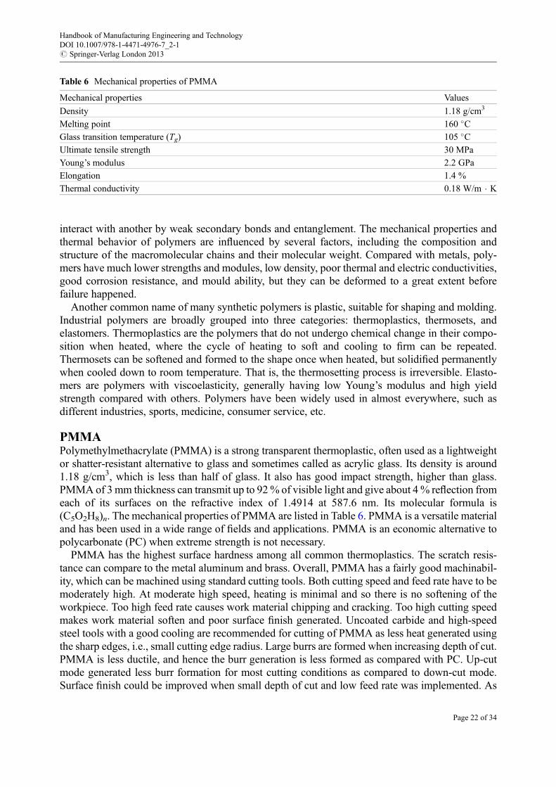
PMMAPolymethylmethacrylate (PMMA) is a strong transparent thermoplastic, often used as a lightweightor shatter-resistant alternative to glass and sometimes called as acrylic glass. Its density is around1.18 g/cm3, which is less than half of glass. It also has good impact strength, higher than glass.PMMA of 3mm thickness can transmit up to 92% of visible light and give about 4% reflection fromeach of its surfaces on the refractive index of 1.4914 at 587.6 nm. Its molecular formula is(C5O2H8)n. The mechanical properties of PMMA are listed in Table 6. PMMA is a versatile materialand has been used in a wide range of fields and applications. PMMA is an economic alternative topolycarbonate (PC) when extreme strength is not necessary.
PMMA has the highest surface hardness among all common thermoplastics. The scratch resis-tance can compare to the metal aluminum and brass. Overall, PMMA has a fairly good machinabil-ity, which can be machined using standard cutting tools. Both cutting speed and feed rate have to bemoderately high. At moderate high speed, heating is minimal and so there is no softening of theworkpiece. Too high feed rate causes work material chipping and cracking. Too high cutting speedmakes work material soften and poor surface finish generated. Uncoated carbide and high-speedsteel tools with a good cooling are recommended for cutting of PMMA as less heat generated usingthe sharp edges, i.e., small cutting edge radius. Large burrs are formed when increasing depth of cut.PMMA is less ductile, and hence the burr generation is less formed as compared with PC. Up-cutmode generated less burr formation for most cutting conditions as compared to down-cut mode.Surface finish could be improved when small depth of cut and low feed rate was implemented. As
Table 6 Mechanical properties of PMMA
Mechanical properties Values
Density 1.18 g/cm3
Melting point 160 �CGlass transition temperature (Tg) 105 �CUltimate tensile strength 30 MPa
Young’s modulus 2.2 GPa
Elongation 1.4 %
Thermal conductivity 0.18 W/m � K
Handbook of Manufacturing Engineering and TechnologyDOI 10.1007/978-1-4471-4976-7_2-1# Springer-Verlag London 2013
Page 22 of 34
there is a material spring back after cutting load released, geometrical control may be a potentialissue for very precise machined PMMA parts (Ampara et al. 2012).
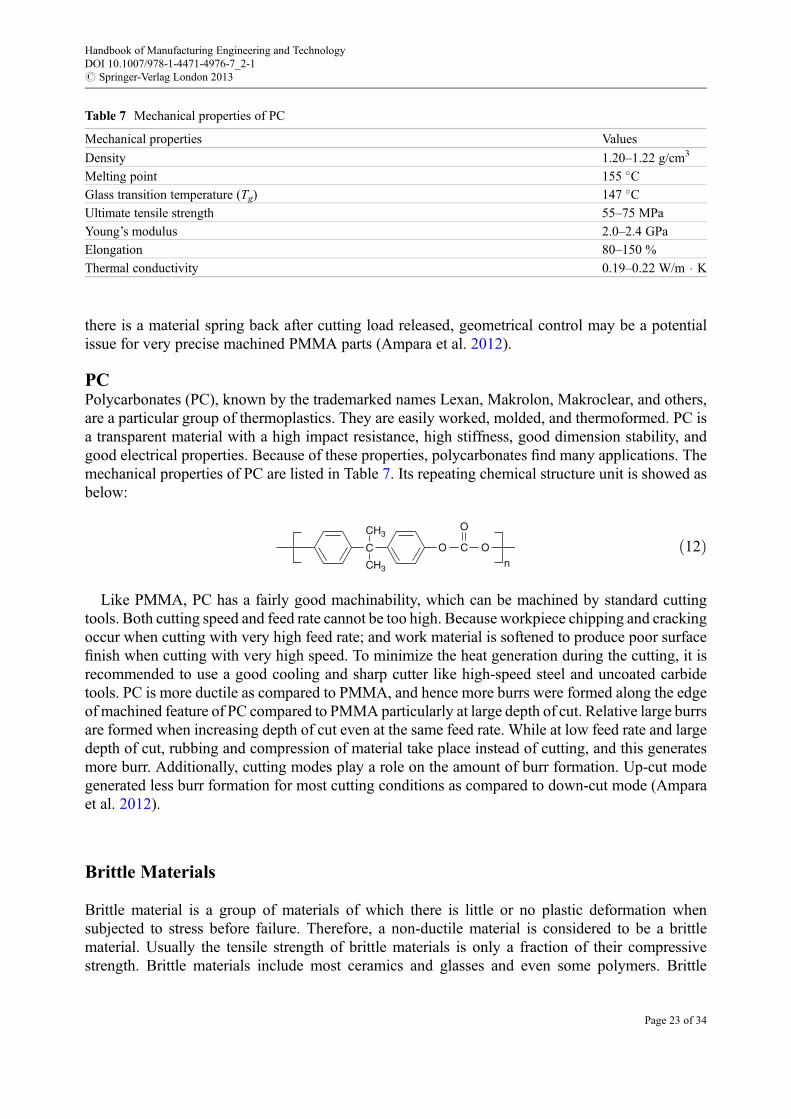
PCPolycarbonates (PC), known by the trademarked names Lexan, Makrolon, Makroclear, and others,are a particular group of thermoplastics. They are easily worked, molded, and thermoformed. PC isa transparent material with a high impact resistance, high stiffness, good dimension stability, andgood electrical properties. Because of these properties, polycarbonates find many applications. Themechanical properties of PC are listed in Table 7. Its repeating chemical structure unit is showed asbelow:
CH3
CH3
C CO O
O
nð12Þ
Like PMMA, PC has a fairly good machinability, which can be machined by standard cuttingtools. Both cutting speed and feed rate cannot be too high. Because workpiece chipping and crackingoccur when cutting with very high feed rate; and work material is softened to produce poor surfacefinish when cutting with very high speed. To minimize the heat generation during the cutting, it isrecommended to use a good cooling and sharp cutter like high-speed steel and uncoated carbidetools. PC is more ductile as compared to PMMA, and hence more burrs were formed along the edgeof machined feature of PC compared to PMMA particularly at large depth of cut. Relative large burrsare formed when increasing depth of cut even at the same feed rate. While at low feed rate and largedepth of cut, rubbing and compression of material take place instead of cutting, and this generatesmore burr. Additionally, cutting modes play a role on the amount of burr formation. Up-cut modegenerated less burr formation for most cutting conditions as compared to down-cut mode (Amparaet al. 2012).
Brittle Materials
Brittle material is a group of materials of which there is little or no plastic deformation whensubjected to stress before failure. Therefore, a non-ductile material is considered to be a brittlematerial. Usually the tensile strength of brittle materials is only a fraction of their compressivestrength. Brittle materials include most ceramics and glasses and even some polymers. Brittle
Table 7 Mechanical properties of PC
Mechanical properties Values
Density 1.20–1.22 g/cm3
Melting point 155 �CGlass transition temperature (Tg) 147 �CUltimate tensile strength 55–75 MPa
Young’s modulus 2.0–2.4 GPa
Elongation 80–150 %
Thermal conductivity 0.19–0.22 W/m � K
Handbook of Manufacturing Engineering and TechnologyDOI 10.1007/978-1-4471-4976-7_2-1# Springer-Verlag London 2013
Page 23 of 34
materials have been widely used in the different areas of the industries due to their unique physical,chemical, optical, and mechanical properties. Unfortunately, brittle materials are very difficult to bemachined and often fractured during machining process.
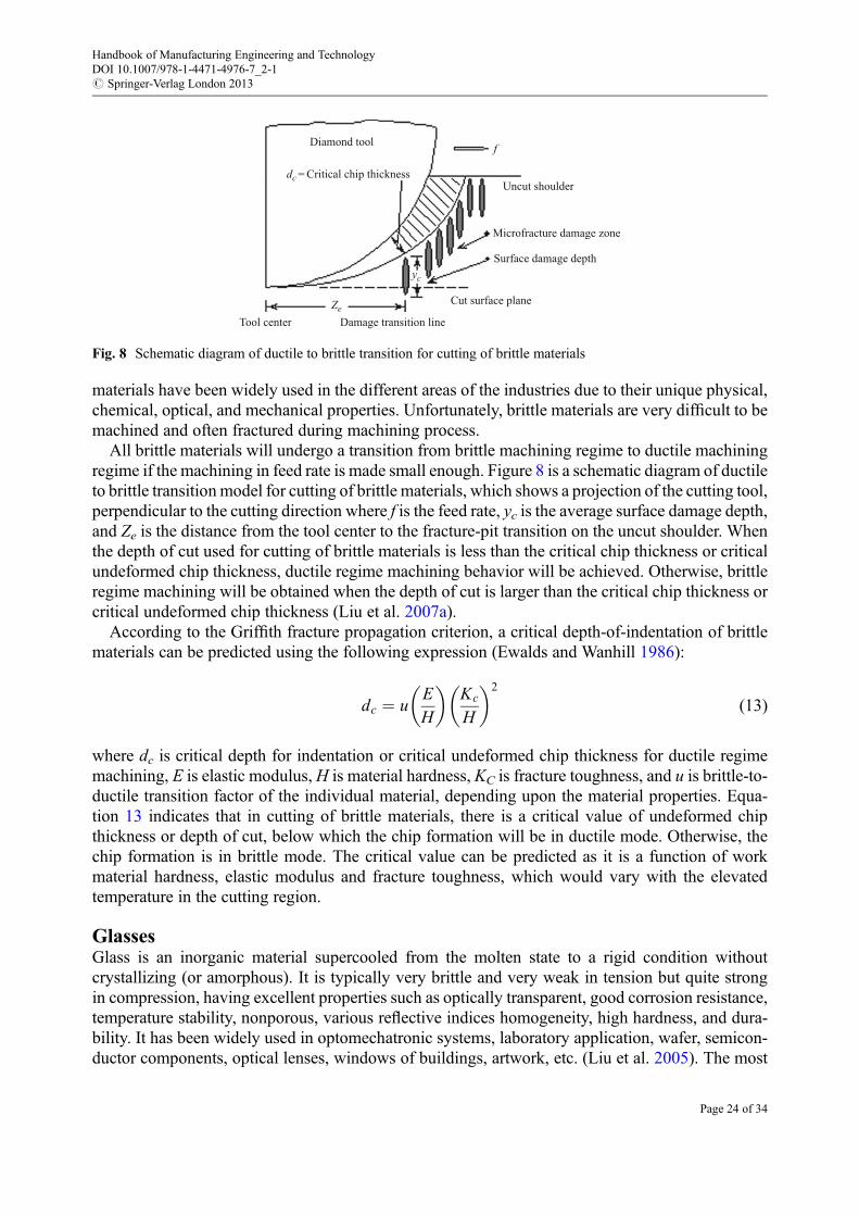
All brittle materials will undergo a transition from brittle machining regime to ductile machiningregime if the machining in feed rate is made small enough. Figure 8 is a schematic diagram of ductileto brittle transition model for cutting of brittle materials, which shows a projection of the cutting tool,perpendicular to the cutting direction where f is the feed rate, yc is the average surface damage depth,and Ze is the distance from the tool center to the fracture-pit transition on the uncut shoulder. Whenthe depth of cut used for cutting of brittle materials is less than the critical chip thickness or criticalundeformed chip thickness, ductile regime machining behavior will be achieved. Otherwise, brittleregime machining will be obtained when the depth of cut is larger than the critical chip thickness orcritical undeformed chip thickness (Liu et al. 2007a).
According to the Griffith fracture propagation criterion, a critical depth-of-indentation of brittlematerials can be predicted using the following expression (Ewalds and Wanhill 1986):
dc ¼ uE
H
� �Kc
H
� �2
(13)
where dc is critical depth for indentation or critical undeformed chip thickness for ductile regimemachining, E is elastic modulus, H is material hardness, KC is fracture toughness, and u is brittle-to-ductile transition factor of the individual material, depending upon the material properties. Equa-tion 13 indicates that in cutting of brittle materials, there is a critical value of undeformed chipthickness or depth of cut, below which the chip formation will be in ductile mode. Otherwise, thechip formation is in brittle mode. The critical value can be predicted as it is a function of workmaterial hardness, elastic modulus and fracture toughness, which would vary with the elevatedtemperature in the cutting region.
GlassesGlass is an inorganic material supercooled from the molten state to a rigid condition withoutcrystallizing (or amorphous). It is typically very brittle and very weak in tension but quite strongin compression, having excellent properties such as optically transparent, good corrosion resistance,temperature stability, nonporous, various reflective indices homogeneity, high hardness, and dura-bility. It has been widely used in optomechatronic systems, laboratory application, wafer, semicon-ductor components, optical lenses, windows of buildings, artwork, etc. (Liu et al. 2005). The most
Diamond tool
Uncut shoulder
Microfracture damage zone
Surface damage depth
Cut surface plane
Damage transition lineTool centerZe
dc= Critical chip thickness
yc
f
Fig. 8 Schematic diagram of ductile to brittle transition for cutting of brittle materials
Handbook of Manufacturing Engineering and TechnologyDOI 10.1007/978-1-4471-4976-7_2-1# Springer-Verlag London 2013
Page 24 of 34
familiar type of glass is soda lime glass composed of about 75% silica (SiO2), sodium oxide (Na2O),and lime calcium oxide (CaO).
As glass is hard and brittle, it is very difficult to be cut and often be fractured during machining.Commonly used machining methods for glass are abrasive processes with either fixed abrasive likegrinding and loose abrasive like abrasive jet machining and ultrasonic machining, where super hardparticles like diamond, CBN, alumina and silicon carbide are used as the abrasive grit. In nature, theyare brittle machining mode to remove the material by fracturing and crack propagation, such that themachined surface is not as good as for industrial application. Subsequently, polishing method isintroduced to remove those damaged layer containing fine cracks to improve the workpiece finalsurface finish. Again, the abrasive type used for polishing can be diamond and CBN grit. However,the material removal rate for those machining methods is very small and particularly polishing isextremely time-consuming.
Ductile mode machining of brittle materials has attracted a lot of interests from both engineers andacademics, because a crack-free surface can be obtained and subsequent polishing is no longernecessary. As early in 1975, improvement in precision diamond grinding mechanism allowed thefirst reproducible evidence of grinding ductility in brittle glass workpiece (Huerta andMalkin 1976).Ultraprecision cutting has carried out to investigate the cutting performance of ZKN7 glass and sodalime glass. Ductile mode cutting of ZKN7 glass has been achieved with single-crystal diamond toolwhen depth of cut is less than 600 nm (Fang and Chen 2000). Ductile mode cutting of sod lime glasshas been achieved with polycrystalline diamond tool when depth of cut is less than 1 μm (Liuet al. 2005). However, this small critical undeformed chip thickness is a bottleneck for the industrialapplication of ductile regime machining. Ultrasonic vibration-assisted ultraprecision machiningmethod was invented in 1992 to improve glass material ductile cutting performance by applyingan ultrasonic vibration on a single-crystal diamond tool along the cutting velocity direction(Moriwaki et al. 1992). In both the conventional cutting and ultrasonic vibration-assisted cutting,the machined grooves formed from ductile mode to brittle mode along with the depth of cutincreasing and exceeding a critical value. Ultrasonic vibration could improve the ductile cuttingperformance of glass up to 1.4 μm critical depth of cut, compared with the critical depth of cut200 nm obtained in the conventional cutting. Studies on ductile mode cutting explore innovatedways continuously to cut glasses using a convention CNC machine tool with TiAlN-coated carbideend mill (Arefin et al. 2007).
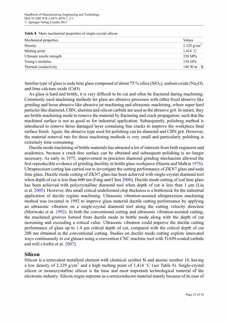
SiliconSilicon is a tetravalent metalloid element with chemical symbol Si and atomic number 14, havinga low density of 2.329 g/cm3 and a high melting point of 1,414 �C (see Table 8). Single-crystalsilicon or monocrystalline silicon is the base and most important technological material of theelectronic industry. Silicon reigns supreme as a semiconductor material mainly because of its ease of
Table 8 Main mechanical properties of single-crystal silicon
Mechanical properties Values
Density 2.329 g/cm3
Melting point 1,414 �CUltimate tensile strength 350 MPa
Young’s modulus 150 GPa
Thermal conductivity 148 W/m � K
Handbook of Manufacturing Engineering and TechnologyDOI 10.1007/978-1-4471-4976-7_2-1# Springer-Verlag London 2013
Page 25 of 34
manufacturing. Single-crystal silicon is not only a dominant substrate material for the fabrication ofmicro electro and micro mechanical components but also an important infrared optical material.
Silicon wafers are fabricated from the single-crystal silicon ingot through slicing, edge grinding,finishing, lapping, and polishing. After integrity circuit (IC) fabrication, back thinning and dicing ofwafers into devices are the subsequent fabrication processes. Actually, all those wafer fabricationprocesses are basically grinding or abrasive processes. The main problems of these grindingprocesses are the subsurface damage and cracks. The average thickness of the wafer subsurfacedamage layer is more than 6 μm even after fine grinding (Liu et al. 2009). It is obviously too costlyand time-consuming to remove the subsurface damaged layer by the subsequent heave chemical–-mechanical polishing (CMP) process.
Tremendous affords have been made on ductile regime grinding and ductile mode cutting ofsingle-crystal silicon wafers, targeting to achieve less subsurface damage so as to speed up the wholesilicon wafer fabrication processes. Nanometric cutting has been carried out to investigate the ductilecutting performance of single-crystal silicon wafers using an ultraprecision lathe with single-crystaldiamond tools of different cutting edge radii. There is an upper bound of the tool cutting edge radiusfor ductile mode chip formation in cutting of silicon. Cutting with tool edge radius larger than theupper bound would not be in a ductile mode (Arefin et al. 2007). There is a critical undeformed chipthickness for a given tool with the tool cutting edge smaller than the upper bound, beyond which thechip formation changes from ductile mode to brittle mode. The ductile-brittle transition of chipformation varies with the tool cutting edge radius. The larger the cutting edge radius, the larger thecritical undeformed chip thickness for the ductile-brittle transition in the chip formation (Liuet al. 2007b). Ductile cutting of silicon can be achieved when the cutting edge radius does notexceed the upper bound value and the undeformed chip thickness is less than the critical value.Cutting mode is mainly determined by tool edge radius and undeformed chip thickness used, whichhas a significant effect on the Ra values of surface roughness for the machined workpiece. Themachined silicon wafer surfaces achieved by ductile cutting were free of micro cracks and fracture(Liu et al. 2009).
CeramicsCeramics represent a broad range of inorganic and nonmetallic materials, typically oxides, borides,carbides, and nitrides; have ionic and covalent bond character and extremely high melting point,>2,000 �C, that are commonly electrical and thermal insulators; and are composed of more than oneelement. Ceramics are generally brittle, porous forms and weak in tension, but in particular, they canbe very hard and wear resistance once fully dense forms made, being excellent cutting and grindingmaterials for metals. Fully dense ceramics can be very efficient thermal conductors, but porousceramics can be very efficient heat insulators. Thus, ceramics are a class of important materialsuseful in both traditional and advanced applications. Commercial and engineering ceramics includealumina (Al2O3), silica, silicates, silicon carbide (SiC), tungsten carbide (WC), silicon nitride(Si3N4), sialons, zirconia (ZrO2), etc. Many ceramics are chemically very inert, strong, and light,making very suitable for biomedical implants. Advanced ceramics are also used in the medicine,electrical, and electronics industries. They are generally very strong and brittle, such that they arevery difficult to be cut or machined. Grinding, polishing, ultrasonic machining, laser machining, andwater jet machining are the commonly used machining methods for ceramics applications.
Tungsten carbide (WC) is an inorganic chemical compound, often simply called carbide and alsocalled cemented carbide, hard metal, or tungsten-carbide cobalt, containing equal parts of tungstenand carbon atoms. It is a metal matrix composite where tungsten carbide particles are the aggregateand metallic cobalt serves as the matrix. Table 9 lists its main mechanical properties. Tungsten
Handbook of Manufacturing Engineering and TechnologyDOI 10.1007/978-1-4471-4976-7_2-1# Springer-Verlag London 2013
Page 26 of 34
carbide has a prosperous future for the sake of its excellent properties such as high hardness, highwear resistance, and good toughness. It has been widely used in the industry for cutting tools,moulds and dies, and other devices. Manufacturers use tungsten carbide as the main material in somehigh-speed drill bits, as it can resist high temperatures and is extremely hard.
When grooving of tungsten carbide using a CNC lathe with CBN tools, there is a transition fromductile mode cutting to brittle mode cutting as the depth of cut continuously increased. Here, thecritical depth of cut for grooving of tungsten carbide is 4.8 μm. When the depth of cut was smallerthan this critical value, the chip formation was in ductile mode. Otherwise, when the depth of cutincreased in exceeding the critical value, the mode of chip formation changed from ductile to brittle(Liu and Li 2001). The tool wear occurs mainly at the tool flank in cutting of tungsten carbide, whichis dominated by diffusion wear, adhesion wear, and abrasion wear. The higher the cutting speed, thelarger the tool wear VBmax and the shorter the tool life. The cutting forces increase gradually with theincrease of the cutting distance and the tool flank wear. However, the machined workpiece surfaceroughness shows no significant change with the progress of the tool flank wear (Liu et al. 2003). Butthe material removal rate in ductile mode cutting of tungsten carbide using conventional machiningmethods remains very small and not efficient. Ultrasonic vibration-assisted cutting has been used toimprove the ductile cutting performance of tungsten carbide. In comparison with conventionalgrooving of tungsten carbide, the critical depth of cut for the transition from ductile to brittle inultrasonic vibration assisted grooving is around 16 μm, several times larger than that in conventionalgrooving (Liu et al. 2004).
Composites
Composite materials, often shortened to composites, are engineered or naturally occurring materialscomposed of two or more distinct phases: matrix phase and dispersed phase, with significantlydifferent physical or chemical properties from those of any constituent materials. The primary phaseis called matrix with a continuous character, which is usually more ductile and less hard phase. Itholds the dispersed phase and shares a load with it. The second phase is called dispersed phaseembedded in the matrix phase in a discontinuous form. Dispersed phase is usually stronger than thematrix phase and thus sometimes called it reinforcing phase.
In general, according to dispersion phase, composites can be segmented into three types: fiberreinforced, particle reinforced, and dispersion strengthened. According to the matrix phase, com-posites can be classified into three groups: metal matrix composite (MMC), ceramic matrixcomposite (CMC), and polymer matrix composite (PMC). Commonly, composites have superior
Table 9 Main mechanical properties of tungsten carbide
Mechanical properties Values
Density 15.63 g/cm3
Melting point 2,870 �CVickers hardness 13.7–14.7 GPa
Transverse rupture strength 2,150 MPa
Young’s modulus 530 GPa
Specific heat capacity 39.8 J/mol � kPoisson’s ratio 0.24
Thermal conductivity 110 W/m � K
Handbook of Manufacturing Engineering and TechnologyDOI 10.1007/978-1-4471-4976-7_2-1# Springer-Verlag London 2013
Page 27 of 34
high strength-to-weight ratio and resistance to corrosion and fatigue. The machinability of compos-ites is very much diverse based upon the matrix materials and reinforcement materials.
Metal Matrix CompositesMetal matrix composites (MMCs) are composed of a metallic matrix and a dispersed ceramic ormetallic phase, which may be classified by the morphology of matrix reinforcement as dispersionstrengthened, particle reinforced or fibre reinforced. Typically, the metal matrix materials of MMCsare aluminum, magnesium, iron, cobalt, copper, and titanium, while the reinforcement materials areoxides, carbides, and graphites. The most widely used MMCs are based on aluminum as a matrix,reinforced with particulate silicon carbide (SiC), which is relatively cheap and has a low density. Thestiffness of aluminum may thus be increased by more than 50 % in particulate composites. Theirhigh strength and stiffness make them being particular attractive materials for aerospace structures.
MMCs can be machined using conventional techniques such as turning, drilling, milling, andgrinding, and nonconventional machining methods including electro-discharge machining (EDM),electro-chemical machining (ECM), laser machining, and abrasive jet machining. But most com-monly used tools are diamond-based cutting tools such as polycrystalline diamond tooling (PCD),and CVD diamond-coated tools due to ceramic particles caused abrasion wear and adhesion wear,although cubic boron nitride (CBN), alumina, silicon carbide, and tungsten carbide tools are alsoused. Built-up edge occurs when cutting of MMCs especially at low cutting speed. The tool lifedecreases while the surface finish slightly improved with an increase in cutting speed, since thecutting temperature increases with the cutting speed. The excessive tool wear and damage associatedwith machining of long-fiber-reinforced MMCs result in the process being uneconomical (Davim2012). In general, aluminum MMCs reinforced with alumina are more difficult to machine thanSiC-reinforced aluminum MMCs.
Ceramic Matrix CompositesCeramic matrix composites (CMCs) are composed of a ceramic matrix and embedded fibers of otherceramic material (dispersed phase) to overcome the major disadvantages of conventional technicalceramics, namely, brittle failure and low fracture toughness, and limited thermal shock resistance.CMCs have attractive high temperature properties, but many are brittle. Therefore, their applicationsare mainly in fields requiring reliability at high temperatures and resistance to corrosion and wear,such as cutting tools, wear-resistant parts, aerospace engine parts, and military parts, as well asenergy-related components. They are generally very difficult to be cut or machined due to highhardness at elevated temperatures. Grinding, polishing, electro-discharge machining (EDM), ultra-sonic machining, laser machining, and water jet machining are the commonly used machiningmethods for CMCs applications.
The inherent challenge in machining of CMCs is the excessive tool wear and subsequentsubsurface damage. Increasing the particle volume fraction results in fast tool wear and subsequentlyaffected the surface finish of the machined workpiece. A higher tool wear is a result of the increasedhard ceramic particle volume fraction in CMCs. PCD tools are the most preferred, while carbidetools are preferred over ceramic tools. Cutting speed, feed rate and depth of cut have a similar effecton tool life and surface finish in machining of CMCs compared to those in machining of metalsalthough some differences are noticeable due to the ceramic particles. In case of using carbide tools,a low cutting speed and a high feed rate are utilized to maximize the tool life (Dandekar and Shin2012).
Handbook of Manufacturing Engineering and TechnologyDOI 10.1007/978-1-4471-4976-7_2-1# Springer-Verlag London 2013
Page 28 of 34

Polymer Matrix CompositePolymer matrix composites (PMCs) are composed of a matrix from thermoset or thermoplastic andembedded glass, carbon, steel, or Kevlar fibers (dispersed phase), characterized by the morphologyof the reinforcement: filler strengthened or fiber reinforced. They comprise a thermoset matrix,which is reinforced with fibers or whiskers of a material of very high tensile strength. PMCsreinforced by long fibers are an important class of materials in advanced structural applicationsdue to their lightweight, high modulus and high specific strength. The use of PMCs is very diverseand far reaching almost all industry sectors with an application ranging from commercial aircraft tosporting goods.
However, because of their anisotropic and heterogeneous nature, PMCs are difficult to machine.They contain strong and very abrasive fibers held together by a relatively weak and brittle matrix,being more prone to damage during machining than conventional metals (Campbell 2006). Car-bides, coated carbides, PCD, and diamond abrasive tools are commonly used for machining ofPMCs. The actual depth of cut are very different from nominal depth of cut in cutting of PMCs,because a part of PMCs is pushed away from the cutting tool during machining and sprang backpartially after the cutting load released. Machined composite surfaces often contain mechanicaldamages such as delamination, fiber pullout, fiber fuzzing, matrix de-cohesion, matrix chipping,cracking, and fiber dislodgements, as well as thermal damage and chemical damage. Debonding andfiber breakage can also take place easily. Due to the much lower thermal conductivity of the fibers(especially glass and aramid), heat buildup can occur rapidly and degrade the matrix, resulting inmatrix cracking and even delamination. That is why it is important to minimize forces and heatgeneration during machining of PMCs. Generally high cutting speeds, low feed rates, and smalldepths of cuts are used to minimize damage (Davim 2009). Other machining methods such as lasermachining and abrasive jet machining are also commonly used for PMC applications.
Machining Economics
Production costs and production rates create a crucial interest to the all manufacturing engineers.Metal cutting economics is to a great extent about making the best use of production resources(Boothroyd and Knight 1989). The variables affecting the economics of a machining operation arenumerous which include the tool material, raw material, over head investment, machine toolcapacity, operating skill, and the cutting conditions.
Basic TermsIn the following discussion, two terms related to machining economics are defined as:
1. Production cost: total average cost to perform the machining operation on a component using onemachine
2. Production time: average time taken to produce one component
Manufacturing is a complex system and usually no single machining operation can completea component fabrication. A high efficiency or production rate would probably mean low productioncost. But these two facts must be taken into account separately, because the machining conditionsproviding maximum production rate may be the conditions giving minimum production cost. Inpractice, the optimum machining conditions can rarely be achieved due to some constraints:
Handbook of Manufacturing Engineering and TechnologyDOI 10.1007/978-1-4471-4976-7_2-1# Springer-Verlag London 2013
Page 29 of 34
• Tool and work material variability• Range of speeds, power, feed, and stability of machines• Inadequate machine tools• Finish, surface integrity, and dimensional accuracy required• Insufficient cost data
The problem is to adjust the machine consistent with constraints so that production can be carriedout as close to optimum machining conditions as possible. And also optimum conditions for onemachining operation may not be the optimum conditions for a complete manufacturing system.
Machining Performance CriteriaIn general, a component manufacturing will involve several machining operations using a variety ofmachine tools, and most machine tools are used for more than one type of component. Thus, theactual economic optimum for any machining operation must consider other processes which will beperformed on that component. The manufacturing company is more interested in the overall profitrather than the individual machining operations and single component in a given period.
The economic criteria normally considered for practical machining operations to choose cuttingspeeds, feeds, tool geometry, tool and work materials, cutting fluids, and machine tools are:
• Minimum cost: increasing the batch size always reduces the cost of production and the economicbatch size for the appreciate machine is depended on both the cutting conditions and work–toolmachinability.
• Maximum production: increasing the batch size increases the maximum production rate.• Maximum profit rate (maximum efficiency): the optimum conditions for maximum profits lies
close to the minimum-cost conditions.
An estimation of cost factors is important as it would affect the optimum machining conditionsselected. The calculating methods for those costs could vary from different manufacturing systemsto different components. Basic elements of cost estimation applicable to most cases can be expressedas
Cpr ¼ Cm þ Ct þ Cs þ Cn (14)
where Cpr is the average cost per piece, Cm is the machining cost, Ct is tooling cost, Cs is tool-changing cost, and Cn is nonproductive or idling cost.
Figure 9 shows the qualitative plots on the effect of cutting speeds on manufacturing costs. Detailsof the manufacturing costs are:
1. Machining cost is direct labor and machine cost with overhead for machining of one component,including operator wage rate and benefits, depreciation rate of machine tool, machine overheadlike machine servicing and maintenance cost, power consumption, etc. The machining time isdetermined by the types of machining operations and cutting conditions used. As shown inFig. 9a, increasing cutting speed will decrease the machining cost as the machining time is less.
2. Tooling cost is the cost of cutting tools and regrinding of regrindable tools, etc., for machining ofone component. As shown in Fig. 9b, increasing cutting speed will also increase the tooling costas the tool wear is fast and more cutting tools are needed to machine the component.
Handbook of Manufacturing Engineering and TechnologyDOI 10.1007/978-1-4471-4976-7_2-1# Springer-Verlag London 2013
Page 30 of 34

3. Tool changing cost is the cost incurred for removing the worn tool from the machine tool, placinga new tool and setting the new tool in the proper position for machining of one component. Asshown in Fig. 9c, increasing cutting speed will also increase the tool changing cost as morecutting tools used need more tool changing times.
4. Nonproductive or idling cost is the cost not directly associated with manufacturing operations,including the cost of loading and unloading component, the idling time cost, and othernon-cutting time costs not included in the total cost per component. As shown in Fig. 9d,increasing cutting speed will not change the nonproductive or idling cost as this cost incurredfor running the company is not associated with the manufacturing operations, regardless of jobtype, batch, and volume. Figure 10 shows the qualitative plots on the effect of cutting speed ontotal manufacturing cost. Note that there is an optimum machining speed for manufacturing cost.The cutting speed close to the optimum condition is known as the high-efficiency machiningrange.
Other factors may limit the selection of optimum machining conditions including maximummachining power and maximum machining force as
Cutting_Power ¼ cnf aab (15)
and
F ¼ kf aab (16)
where c, k, a, and b are constants, f is feed rate, v is cutting speed, and a is depth of cut. All those
Cutting speed
a b
c d
Cutting speed
Cutting speed
Cutting speed
Non-productive cost
Mac
hini
ng c
ost
Machining cost
Tool
cha
ngin
g co
st
Tool changing cost
Idlin
g co
stTo
olin
g co
st
Tooling cost
3
2
1
4
Fig. 9 Effect of cutting speed on manufacturing costs
Handbook of Manufacturing Engineering and TechnologyDOI 10.1007/978-1-4471-4976-7_2-1# Springer-Verlag London 2013
Page 31 of 34

cutting speed, feed rate, and depth of cut selection must not exceed the available cutting power andmachining force.
Summary
In this chapter, machinability has been introduced to indicate one engineering material how easy ordifficult it is by machining to achieve an acceptable surface finish. Machinability could be consid-ered as a material property, but not a unique property. When assessing a material machinability, allother aspects of the machining system must be considered concurrently. An understanding of theinteractions between tool and work materials at the tool–work interface would benefit to machiningbehavior and machinability. Tool material and cutting speed perhaps are the two most importantparameters for engineering material machinability assessments. Engineering materials could bedeveloped with improved machinability or more uniform machinability through microstructuremodification and chemical components adjustment, making it easy to machine and achieving lowtool wear rate, improved chip formation, and reduced cutting forces. Advance developed toolmaterials with high thermal hardness and wear resistance would improve the material machinability.
References
Akbarpour MR (2007) High temperature mechanical properties of triple phase steels. Mat Lett61:1023–1026
Ampara A, Shaw KC, Liu K (2012) An experimental study of micromilling of polymer materials formicrofluidic applications. Int J Abras Technol 5:286–298
Arefin S, Li XP, RahmanM, Liu K (2007) The upper bound of tool edge radius for nanoscale ductilecutting of silicon wafer. Int J Adv Manuf Technol 31:655–662
Boothroyd G, Knight WA (1989) Fundamentals of machining and machine tools, 2nd edn. MercelDecker, New York
Campbell FC (2006) Manufacturing technology for aerospace structural materials. Elsevier, NewYork
Total cost
Cutting speedSpeed forminimum cost
Cos
t
1
4
3
2
Fig. 10 Effect of cutting speed on total manufacturing cost
Handbook of Manufacturing Engineering and TechnologyDOI 10.1007/978-1-4471-4976-7_2-1# Springer-Verlag London 2013
Page 32 of 34
Codrington J, Nguyen P, Ho SY, Kotousov A (2009) Induction heating apparatus for high temper-ature testing of thermo-mechanical properties. Appl Therm Eng 29:2783–2789
Dandekar CR, Shin YC (2012) Modeling of machining of composite materials: a review. Int J MachTool Manuf 57:102–121
Davim JP (2009) Machining of composite materials. Wiley, LondonDavim JP (2012) Machining of metal matrix composites. Springer, LondonEwalds HL, Wanhill RJH (1986) Fracture mechanics. Edward Arnold, LondonEzugwu EO, Wang ZM (1997) Titanium alloys and their machinability – a review. J Mater Process
Technol 68:262–274Fang FZ, Chen LJ (2000) Ultra-precision cutting for ZKN7 glass. Ann CIRP 49:17–20Finn ME (1989) Metals handbook: machining, vol 16, 9th edn. ASM International, OhioHuerta M, Malkin S (1976) Grinding of glass: the mechanics of the process. ASME Trans J Eng Ind
98:459–467Irwin GR (1957) Analysis of stress and strain near the end of a crack traversing a plate. ASME Trans
J Appl Mech 24:361–364Kendall K (1976) Interfacial cracking of a composite. J Mater Sci 11:1267–1269Liu K, Li XP (2001) Ductile cutting of tungsten carbide. J Mater Process Technol 113:348–354Liu K, Li XP, RahmanM, Liu XD (2003) CBN tool wear in ductile cutting of tungsten carbide. Wear
255:1344–1351Liu K, Li XP, Rahman M, Liu XD (2004) Study of ductile mode cutting in grooving of tungsten
carbide with and without ultrasonic vibration. Int J Adv Manuf Technol 24:389–394Liu K, Li XP, Liang SY, Liu XD (2005) Nanometer scale ductile mode cutting of soda-lime glass.
J Manuf Process 7:95–101Liu K, Li XP, Liang SY (2007a) The mechanism of ductile chip formation in cutting of brittle
materials. Int J Adv Manuf Technol 33:875–884Liu K, Li XP, Rahman M, Neo KS, Chan CC, Liu XD (2007b) A study of the effect of tool cutting
edge radius on ductile cutting of silicon wafers. Int J Adv Manuf Technol 32:631–637Liu K, Zuo DW, Li XP, RahmanM (2009) Nanometric ductile cutting characteristics of silicon wafer
using single crystal diamond tools. J Vac Sci Technol B 27:1361–1366Mills B, Redford AH (1983) Machinability of engineering materials. Applied Science Publishers,
LondonMoriwaki T, Shmoto E, Inoue K (1992) Ultraprecision ductile cutting of glass by applying ultrasonic
vibration. Ann CIRP 41:141–144Shaw MC (1983) Metal cutting principles. Clarendon, OxfordTashM, Samuel FH,Mucciardi F, Doty HW,Valtierra S (2006) Effect of metallurgical parameters on
the machinability of heat-treated 356 and 319 aluminium alloys. J Mat Sci Eng 434:207–217Trent EM, Wright PK (2000) Metal cutting, 4th edn. Butterworth-Heinemann, Woburn
Handbook of Manufacturing Engineering and TechnologyDOI 10.1007/978-1-4471-4976-7_2-1# Springer-Verlag London 2013
Page 33 of 34

Index Terms:
Aluminium 12Brittle materials 24Ceramics 27Composites 29Copper 15Ductile mode machining 25Fracture toughness 8Glasses 25Hardnessis 5Iron 17Machinability 31Machining economics 32Material removal rate 3Nickel 21Polymer 22Silicon 26Steel 17Titanium 19Tungsten carbide 26Yield strength 7
Handbook of Manufacturing Engineering and TechnologyDOI 10.1007/978-1-4471-4976-7_2-1# Springer-Verlag London 2013
Page 34 of 34