mac-address - Cisco - Global Home · PDF filemac-address IBM-469 Cisco IOS Bridging Command...
101
mac-address IBM-469 Cisco IOS Bridging Command Reference March 2013 mac-address To modify the default MAC address of an interface to some user-defined address, use the mac-address command in interface configuration mode. To return to the default MAC address on the interface, use the no form of this command. mac-address ieee-address no mac-address ieee-address Syntax Description Defaults The interface uses a default MAC address that is derived from the base address stored in the electrically erasable programmable read-only memory (EEPROM). Command Modes Interface configuration Usage Guidelines Be sure that no other interface on the network is using the MAC address that you assign. There is a known defect in earlier forms of this command when the Texas Instruments Token Ring MAC firmware is used. This implementation is used by Proteon, Apollo, and IBM RTs. A host using a MAC address whose first two bytes are zeros (such as a Cisco router) will not properly communicate with hosts using that form of this command of TI firmware. There are two solutions. The first involves installing a static Routing Information Field (RIF) entry for every faulty node with which the router communicates. If there are many such nodes on the ring, this may not be practical. The second solution involves setting the MAC address of the Cisco Token Ring to a value that works around the problem. This command forces the use of a different MAC address on the specified interface, thereby avoiding the Texas Instrument MAC firmware problem. It is up to the network administrator to ensure that no other host on the network is using that MAC address. Examples The following example sets the MAC layer address, where xx.xxxx is an appropriate second half of the MAC address to use: interface tokenring 0 mac-address 5000.5axx.xxxx The following example changes the default MAC address on the interface to 1111.2222.3333: Router# configure terminal Router(config)# interface fastethernet 2/1/1 Router(config-if)# mac-address 1111.2222.3333 Related Commands ieee-address 48-bit IEEE MAC address written as a dotted triple of four-digit hexadecimal numbers.
Transcript of mac-address - Cisco - Global Home · PDF filemac-address IBM-469 Cisco IOS Bridging Command...

mac-address
mac-addressTo modify the default MAC address of an interface to some user-defined address, use the mac-address command in interface configuration mode. To return to the default MAC address on the interface, use the no form of this command.
mac-address ieee-address
no mac-address ieee-address
Syntax Description
Defaults The interface uses a default MAC address that is derived from the base address stored in the electrically erasable programmable read-only memory (EEPROM).
Command Modes Interface configuration
Usage Guidelines Be sure that no other interface on the network is using the MAC address that you assign.
There is a known defect in earlier forms of this command when the Texas Instruments Token Ring MAC firmware is used. This implementation is used by Proteon, Apollo, and IBM RTs. A host using a MAC address whose first two bytes are zeros (such as a Cisco router) will not properly communicate with hosts using that form of this command of TI firmware.
There are two solutions. The first involves installing a static Routing Information Field (RIF) entry for every faulty node with which the router communicates. If there are many such nodes on the ring, this may not be practical. The second solution involves setting the MAC address of the Cisco Token Ring to a value that works around the problem.
This command forces the use of a different MAC address on the specified interface, thereby avoiding the Texas Instrument MAC firmware problem. It is up to the network administrator to ensure that no other host on the network is using that MAC address.
Examples The following example sets the MAC layer address, where xx.xxxx is an appropriate second half of the MAC address to use:
interface tokenring 0 mac-address 5000.5axx.xxxx
The following example changes the default MAC address on the interface to 1111.2222.3333:
Router# configure terminalRouter(config)# interface fastethernet 2/1/1Router(config-if)# mac-address 1111.2222.3333
Related Commands
ieee-address 48-bit IEEE MAC address written as a dotted triple of four-digit hexadecimal numbers.
IBM-469Cisco IOS Bridging Command Reference
March 2013

mac-address
Command Description
show interfaces fastethernet Displays information about the Fast Ethernet interfaces.
show interfaces gigabitethernet Displays information about the Gigabit Ethernet interfaces.
IBM-470Cisco IOS Bridging Command Reference
March 2013

maximum-lus
maximum-lusTo limit the number of logical unit (LU) control blocks that will be allocated for the TN3270 server, use the maximum-lus command in TN3270 server configuration mode. To restore the default value, use the no form of this command.
maximum-lus number
no maximum-lus
Syntax Description
Defaults Because of the license structure, the default is 2100, which represents the limit of the lower-priced license (2000) plus a 5 percent buffer. If you configure a value greater than the default, a license reminder is displayed.
Command Modes TN3270 server configuration
Command History
Usage Guidelines The maximum-lus command is valid only on the virtual channel interface. Although the value may be varied at any time, reducing it below the current number of LU control blocks will not release those blocks until a physical unit (PU) is inactivated by Deactivate Physical Unit (DACTPU) or by using the no pu command.
If the number of LUs in use reaches 94 percent of the current setting, a warning message is displayed on the console. To prevent redundant messages, the threshold for generating such messages is raised for a period.
The TN3270 server attempts to allocate one LU control block for each LU activated by the hosts. In the case of dynamic definition of dependent LU (DDDLU) the control block is allocated when the client requests the LU, in anticipation of an activate logical unit (ACTLU) from the system services control points (SSCP) host.
By limiting the number of LU control blocks allocated, you can make sure enough memory is available to support other Cisco Mainframe Channel Connection (CMCC) functions. The control blocks themselves take about 1K bytes per LU. During session activity, a further 2K per LU may be needed for
number Maximum number of LU control blocks allowed. The allowed range is from 0 to 32000. However, the practical upper limit for concurrently operating TN3270 sessions depends on the hardware and usage characteristics. The default is 2100.
Release Modification
11.2 This command was introduced.
12.2(33)SRA This command was integrated into Cisco IOS Release 12.2(33)SRA.
12.2SX This command is supported in the Cisco IOS Release 12.2SX train. Support in a specific 12.2SX release of this train depends on your feature set, platform, and platform hardware.
IBM-471Cisco IOS Bridging Command Reference
March 2013

maximum-lus
data. On a Channel Interface Processor (CIP), 32 MB of memory will support 4000 LUs. To support more than 4000 LUs, we recommend 64 MB of memory. On an XCPA, 8 MB of memory supports 1000 LUs.
Examples The following example allows 5000 LU control blocks to be allocated:
maximum-lus 5000
Related Commands Command Description
client ip Adds an IP subnet to a client subnet response-time group.
pu (TN3270) Creates a PU entity that has its own direct link to a host and enters PU configuration mode.
pu (DLUR) Creates a PU entity that has no direct link to a host and enters DLUR PU configuration mode.
IBM-472Cisco IOS Bridging Command Reference
March 2013

max-llc2-rcvbuffs
max-llc2-rcvbuffsTo configure the number of receive DMA buffers that are used by the LLC2 stack on the CIP/XCPA, use the max-llc2-rcvbuffs internal adapter configuration command. Use the no form of this command to revert to the default setting.
max-llc2-rcvbuffs buffers
no max-llc2-rcvbuffs buffers
Syntax Description
Defaults 500 buffers
Command Modes Virtual interface configuration
Command History
Examples The following example configures the max-llc2-rcvbuffs for 750 buffers on Channel interface 4/2:
interface Channel4/2 max-llc2-rcvbuffs 750lan TokenRing 12 source-bridge 16 1 500 adapter 0 4000.cafe.0000 llc2 Nw 31 llc2 rnr-activated adapter 1 4000.cafe.0001
Related Commands
buffers The number of receive DMA buffers that are used by the LLC2 stack on the CIP/XCPA. The allowed range is from 500 to 1250 in multiples of 50. The default is 500.
Release Modification
12.1 This command was introduced.
12.2(33)SRA This command was integrated into Cisco IOS Release 12.2(33)SRA.
12.2SX This command is supported in the Cisco IOS Release 12.2SX train. Support in a specific 12.2SX release of this train depends on your feature set, platform, and platform hardware.
Command Description
llc2 nw Increases the window size for consecutive good I-frames received.
llc2 rnr-activated Invokes dynamic windowing logic for a link station when the router receives an RNR from the remote link station.
IBM-473Cisco IOS Bridging Command Reference
March 2013

max-llc2-sessions
max-llc2-sessionsTo specify the maximum number of Logical Link Control, type 2 (LLC2) sessions supported on the Cisco Mainframe Channel Connection (CMCC) adapter, use the max-llc2-sessions command in interface configuration mode. To restore the default value, use the no form of this command.
max-llc2-sessions number
no max-llc2-sessions number
Syntax Description
Defaults The default number of sessions is 256.
Command Modes Interface configuration
Command History
Usage Guidelines This command is configured on the virtual interface of a Channel Interface Processor (CIP), and the physical interface of a Channel Port Adapter (CPA). If you do not configure this parameter on the CMCC adapter, then the limit of LLC2 sessions is 256.
This command will fail if not enough memory is available on the CMCC adapter to support the specified number of LLC2 sessions.
Note A value of 0 sets the maximum number of LLC2 sessions to the default value of 256. In this case, the value does not appear in your configuration when you use the show run command.
Examples The following example limits the maximum number of LLC2 sessions to 212:
max-llc2-sessions 212
number A value in the range from 1 to 6000 Logical Link Control (LLC) sessions. If this command is not configured, the default is 256 sessions.
Release Modification
11.0 This command was introduced.
12.2(33)SRA This command was integrated into Cisco IOS Release 12.2(33)SRA.
12.2SX This command is supported in the Cisco IOS Release 12.2SX train. Support in a specific 12.2SX release of this train depends on your feature set, platform, and platform hardware.
IBM-474Cisco IOS Bridging Command Reference
March 2013

multiring
multiringTo enable collection and use of Routing Information Field (RIF) information, use the multiring command in interface configuration mode. To disable the use of RIF information for the protocol specified, use the no form of this command.
multiring {protocol [all-routes | spanning] | all | other}
no multiring {protocol [all-routes | spanning] | all | other}
Syntax Description
Defaults Disabled
Command Modes Interface configuration
Command History
protocol Specifies a protocol. The following protocols are supported:
• appletalk—AppleTalk Phase 1 and 2
• clns—ISO CLNS
• decnet—DECnet Phase IV
• ip—IP
• ipx—Novell IPX
all-routes (Optional) Uses all-routes explorers.
spanning (Optional) Uses spanning-tree explorers.
all Enables the multiring for all frames.
other Enables the multiring for any routed frame not included in the previous list of supported protocols.
Release Modification
10.0 This command was introduced.
11.1 The following keywords were added:
• all-routes
• spanning
12.2(13)T The following values for the protocol argument were removed:
• apollo
• vines
• xns
12.2(33)SRA This command was integrated into Cisco IOS Release 12.2(33)SRA.
12.2SX This command is supported in the Cisco IOS Release 12.2SX train. Support in a specific 12.2SX release of this train depends on your feature set, platform, and platform hardware.
IBM-475Cisco IOS Bridging Command Reference
March 2013

multiring
Usage Guidelines Level 3 routers that use protocol-specific information (for example, Novell IPX or XNS headers) rather than MAC information to route datagrams also must be able to collect and use RIF information to ensure that they can send datagrams across a source-route bridge. The software default is to not collect and use RIF information for routed protocols. This allows operation with software that does not understand or properly use RIF information.
Note When you are configuring DLSw+ over FDDI, the multiring command supports only IP and IPX.
The multiring command allows for per-protocol specification of the interface’s ability to append RIFs to routed protocols. When it is enabled for a protocol, the router will source packets that include information used by source-route bridges. This allows a router with Token Ring interfaces, for the protocol or protocols specified, to connect to a source-bridged Token Ring network. If a protocol is not specified for multiring, the router can route packets only to nodes directly connected to its local Token Ring.
Examples The following example enables IP and Novell IPX bridging on a Token Ring interface. RIFs will be generated for IP frames, but not for the Novell IPX frames.
! commands that follow apply to interface token 0interface tokenring 0! enable the Token Ring interface for IP ip address 131.108.183.37 255.255.255.0! generate RIFs for IP frames multiring ip! enable the Token Ring interface for Novell IPX novell network 33
Related Commands Command Description
clear rif-cache Clears the entire RIF cache.
rif Enters static source-route information into the RIF cache.
rif timeout Determines the number of minutes an inactive RIF entry is kept.
show rif Displays the current contents of the RIF cache.
xns encapsulation Selects the type of encapsulation used on a Token Ring interface.
IBM-476Cisco IOS Bridging Command Reference
March 2013

name
nameTo assign a name to the internal adapter, use the name command in internal adapter configuration mode. To remove the name assigned to an internal adapter, use the no form of this command.
name name
no name name
Syntax Description
Defaults No default behavior or values
Command Modes Internal adapter configuration
Command History
Examples The following example assigns a name to an internal adapter interface:
name VTAM_B14
Related Commands
name Name that identifies this internal adapter. The name consists of up to eight characters (not including blank spaces).
Release Modification
11.0 This command was introduced.
12.2(33)SRA This command was integrated into Cisco IOS Release 12.2(33)SRA.
12.2SX This command is supported in the Cisco IOS Release 12.2SX train. Support in a specific 12.2SX release of this train depends on your feature set, platform, and platform hardware.
Command Description
adapter Configures internal adapters.
IBM-477Cisco IOS Bridging Command Reference
March 2013
ncia
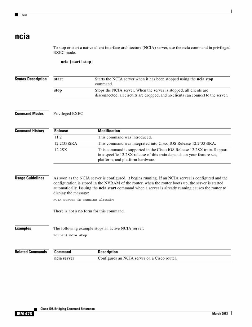
nciaTo stop or start a native client interface architecture (NCIA) server, use the ncia command in privileged EXEC mode.
ncia {start | stop}
Syntax Description
Command Modes Privileged EXEC
Command History
Usage Guidelines As soon as the NCIA server is configured, it begins running. If an NCIA server is configured and the configuration is stored in the NVRAM of the router, when the router boots up, the server is started automatically. Issuing the ncia start command when a server is already running causes the router to display the message:
NCIA server is running already!
There is not a no form for this command.
Examples The following example stops an active NCIA server:
Router# ncia stop
Related Commands
start Starts the NCIA server when it has been stopped using the ncia stop command.
stop Stops the NCIA server. When the server is stopped, all clients are disconnected, all circuits are dropped, and no clients can connect to the server.
Release Modification
11.2 This command was introduced.
12.2(33)SRA This command was integrated into Cisco IOS Release 12.2(33)SRA.
12.2SX This command is supported in the Cisco IOS Release 12.2SX train. Support in a specific 12.2SX release of this train depends on your feature set, platform, and platform hardware.
Command Description
ncia server Configures an NCIA server on a Cisco router.
IBM-478Cisco IOS Bridging Command Reference
March 2013

ncia client
ncia clientTo configure a native client interface architecture (NCIA) client on a Cisco router, use the ncia client command in global configuration mode. To remove the configuration, use the no form of this command.
ncia client server-number client-ip-address virtual-mac-address [sna | all]
no ncia client server-number client-ip-address virtual-mac-address [sna | all]
Syntax Description
Defaults No NCIA client is configured.
Command Modes Global configuration
Command History
Usage Guidelines You must use the ncia server command to configure an NCIA server on the router before using the ncia client command to configure an NCIA client.
The purpose in configuring a client is so the NCIA server can connect outward to a client. When an end station on the LAN side tries to connect to a client, the end station sends an explorer. When the server receives this explorer, the server tries to match the MAC address in the client database. If it finds a match, the server then connects to that client. If the ability for the server to connect outward to clients is not needed, there is no reason to configure any clients.
Each client is assigned a MAC address from the pool created by the ncia server command. There are two exceptions to this guideline:
• A MAC address outside the pool created by the ncia server command can be defined in the ncia client command.
server-number Number assigned to identify the server. Currently, the server number must be configured with a value of 1.
client-ip-address IP address of the client.
virtual-mac-address Virtual MAC address of the client.
sna (Optional) NCIA client only supports Systems Network Architecture (SNA) traffic.
all (Optional) NCIA client supports all types of traffic. If you do not specify all as the supported traffic type when you configure an NCIA client, the client supports only SNA traffic.
Release Modification
11.2 This command was introduced.
12.2(33)SRA This command was integrated into Cisco IOS Release 12.2(33)SRA.
12.2SX This command is supported in the Cisco IOS Release 12.2SX train. Support in a specific 12.2SX release of this train depends on your feature set, platform, and platform hardware.
IBM-479Cisco IOS Bridging Command Reference
March 2013

ncia client
When a client configured with a MAC address outside the pool connects to the server, the client’s configured MAC address is used, rather than allocating a new one from the pool.
• If a client has its own MAC address, it uses that address.
The MAC address is recognized during the “capability exchange” period when the client establishes a session with the NCIA server. Normally, it is not necessary to configure any client. The server accepts a connection from any unconfigured client. If the unconfigured client does not have its own MAC address, a MAC address from the pool will be assigned to it. If the unconfigured client has its own MAC address, that MAC address is used. If the client has its own MAC address and it is configured using the ncia client command, the two MAC addresses must match; otherwise, the connection will not be established.
If you do not specify the all keyword as the supported traffic type when you configure an NCIA client, the client only supports only SNA traffic.
Examples The following example configures an NCIA client on a router:
ncia client 1 10.2.20.5 1111.2222.3333
Related Commands Command Description
ncia server Configures an NCIA server on a Cisco router.
dlsw local-peer Defines the parameters of the data-link switching plus (DLSw+) local peer.
IBM-480Cisco IOS Bridging Command Reference
March 2013

ncia rsrb
ncia rsrbTo configure an remote source-route bridging (RSRB) ring to associate with an native client interface architecture (NCIA) server on a Cisco router, use the ncia rsrb command in global configuration mode. To remove the configuration, use the no form of this command.
ncia rsrb virtual-ring local-bridge local-ring ncia-bridge ncia-ring virtual-mac-address
no ncia rsrb
Syntax Description
Defaults No RSRB ring is configured.
Command Modes Global configuration
Command History
Usage Guidelines You must use the ncia server command to configure an NCIA server on the router before using the ncia rsrb command to configure an RSRB ring to associate with the server.
Examples The following example configures a virtual ring to associate with an NCIA server on a Cisco router:
source-bridge ring-group 22source-bridge ring-group 44ncia rsrb 44 4 33 3 22 1111.1111.2222
virtual-ring RSRB ring group number. This number corresponds to the ring-number keyword defined by a source-bridge ring-group command.
local-bridge Number of the bridge connecting the virtual ring and the local ring.
local-ring Number of the virtual ring connecting the virtual ring and the NCIA ring.
ncia-bridge Number of the bridge connecting the local ring and the NCIA ring.
ncia-ring NCIA ring group number. This number corresponds to the ring-number keyword defined by a source-bridge ring-group command.
virtual-mac-address Local ring virtual MAC address.
Release Modification
11.2 This command was introduced.
12.2(33)SRA This command was integrated into Cisco IOS Release 12.2(33)SRA.
12.2SX This command is supported in the Cisco IOS Release 12.2SX train. Support in a specific 12.2SX release of this train depends on your feature set, platform, and platform hardware.
IBM-481Cisco IOS Bridging Command Reference
March 2013

ncia rsrb
Related Commands Command Description
ncia server Configures an NCIA server on a Cisco router.
source-bridge ring-group Defines or removes a ring group from the configuration.
IBM-482Cisco IOS Bridging Command Reference
March 2013

ncia server
ncia serverTo configure an native client interface architecture (NCIA) server on a Cisco router, use the ncia server command in global configuration mode. To remove the configuration, use the no form of this command.
ncia server server-number server-ip-address server-virtual-mac-address virtual-mac-address virtual-mac-range [inbound-only] [keepalive seconds] [tcp_keepalive minutes]
no ncia server
Syntax Description
Defaults No NCIA server is configured.
Command Modes Global configuration
Command History
server-number Number assigned to identify the server. Currently, the server number must be configured with a value of 1.
server-ip-address IP address used to accept the incoming connection, or to make an outgoing connection.
server-virtual-mac-address MAC address of the server.
virtual-mac-address The first MAC address of the virtual MAC address pool.
virtual-mac-range The range of virtual MAC addresses that can be assigned to the client. The valid range is from 1 to 4095. This number sets the upper limit on the number of contiguous MAC addresses that make up the MAC address pool.
inbound-only (Optional) When the inbound-only keyword is configured, the NCIA server cannot make an outgoing connection.
keepalive seconds (Optional) Keepalive interval in seconds. The valid range is from 0 to 1200. Setting the value to 0 turns the keepalive off.
tcp_keepalive minutes (Optional) TCP keepalive processing interval in minutes. The valid range is from 0 to 99 minutes. Setting the value to 0 stops TCP from sending keepalive packets when an NCIA client is idle. If no tcp_keepalive value is set, the default waiting period for TCP keepalive packets is 20 minutes.
Release Modification
11.2 This command was introduced.
12.2(33)SRA This command was integrated into Cisco IOS Release 12.2(33)SRA.
12.2SX This command is supported in the Cisco IOS Release 12.2SX train. Support in a specific 12.2SX release of this train depends on your feature set, platform, and platform hardware.
IBM-483Cisco IOS Bridging Command Reference
March 2013

ncia server
Usage Guidelines Before configuring an NCIA server, you must use the dlsw local-peer command to configure a data-link switching plus (DLSw+) local peer on this router. Depending on your network design, you may need to use the ncia client command to configure an NCIA client on this router (optional), or use the ncia rsrb command to configure an remote source-route bridging (RSRB) ring to associate with this router (optional).
If you use the inbound-only keyword, there is no need to configure any NCIA clients (the server does not make out-going connections).
In a downstream physical unit (DSPU) configuration, before a client can establish a connection to a downstream physical unit (PU), such as a PC or workstation, the MAC address of the server (server-virtual-mac-address) must be defined at the PC or workstation as the destination MAC address. This MAC address appears as the server MAC address in the output of the show ncia circuits command.
Examples The following example configures an NCIA server on a Cisco router:
ncia server 1 10.2.20.4 4000.3174.0001 4000.0000.0001 128 keepalive 0 tcp_keepalive 0
Related Commands Command Description
dlsw local-peer Defines the parameters of the DLSw+ local peer.
ncia client Configures an NCIA client on a Cisco router.
ncia rsrb Configures an RSRB ring to associate with an NCIA server on a Cisco router.
IBM-484Cisco IOS Bridging Command Reference
March 2013

netbios access-list bytes
netbios access-list bytesTo define the offset and hexadecimal patterns with which to match byte offsets in NetBIOS packets, use the netbios access-list bytes command in global configuration mode. To remove an entire list or the entry specified with the pattern argument, use the no form of this command.
netbios access-list bytes name {permit | deny} offset pattern
no netbios access-list bytes name [permit | deny]
Syntax Description
Defaults No offset or pattern is defined.
Command Modes Global configuration
Command History
Usage Guidelines For offset pattern matching, the byte pattern must be an even number of hexadecimal digits in length.
The byte pattern must be no more than 16 bytes (32 hexadecimal digits) in length.
As with all access lists, the NetBIOS access lists are scanned in order.
You can specify a wildcard character in the byte string indicating that the value of that byte does not matter in the comparison. This is done by specifying two asterisks (**) in place of digits for that byte. For example, the following command would match 0xabaacd, 0xab00cd, and so on:
netbios access-list bytes marketing permit 3 0xab**cd
name Name of the access list being defined.
permit Permits the condition.
deny Denies the condition.
offset Decimal number indicating the number of bytes into the packet where the byte comparison should begin. An offset of zero points to the very beginning of the NetBIOS header. Therefore, the NetBIOS delimiter string (0xFFEF), for example, begins at offset 2.
pattern Hexadecimal string of digits representing a byte pattern. The pattern argument must conform to certain conventions described in the “Usage Guidelines” section.
Release Modification
10.0 This command was introduced.
12.2(33)SRA This command was integrated into Cisco IOS Release 12.2(33)SRA.
12.2SX This command is supported in the Cisco IOS Release 12.2SX train. Support in a specific 12.2SX release of this train depends on your feature set, platform, and platform hardware.
IBM-485Cisco IOS Bridging Command Reference
March 2013

netbios access-list bytes
Examples The following example shows how to configure for offset pattern matching:
netbios access-list bytes marketing permit 3 0xabcd
In the following example, the byte pattern would not be accepted because it must be an even number of hexadecimal digits:
netbios access-list bytes marketing permit 3 0xabc
In the following example, the byte pattern would not be permitted because the byte pattern is longer than 16 bytes in length:
netbios access-list bytes marketing permit 3 00112233445566778899aabbccddeeff00
The following example would match 0xabaacd, 0xab00cd, and so on:
netbios access-list bytes marketing permit 3 0xab**cd
The following example deletes the entire marketing NetBIOS access list named marketing:
no netbios access-list bytes marketing
The following example removes a single entry from the list:
no netbios access-list bytes marketing deny 3 0xab**cd
In the following example, the first line serves to deny all packets with a byte pattern starting in offset 3 of 0xab. However, this denial would also include the pattern 0xabcd because the entry permitting the pattern 0xabcd comes after the first entry:
netbios access-list bytes marketing deny 3 0xabnetbios access-list bytes marketing permit 3 0xabcd
Related Commands Command Description
netbios input-access-filter bytes Defines a byte access list filter on incoming messages. T
netbios output-access-filter bytes Defines a byte access list filter on outgoing messages.
IBM-486Cisco IOS Bridging Command Reference
March 2013

netbios access-list host
netbios access-list hostTo assign the name of the access list to a station or set of stations on the network, use the netbios access-list host command in global configuration mode. The NetBIOS station access list contains the station name to match, along with a permit or deny condition. To remove either an entire list or just a single entry from a list, depending upon the value given for pattern argument, use the no form of this command.
netbios access-list host name {permit | deny} pattern
no netbios access-list host name {permit | deny} pattern
Syntax Description
Defaults No access list is assigned.
Command Modes Global configuration
Command History
Usage Guidelines Table 15 explains the pattern-matching characters that can be used.
name Name of the access list being defined.
permit Permits the condition.
deny Denies the condition.
pattern A set of characters. The characters can be the name of the station, or a combination of characters and pattern-matching symbols that establish a pattern for a set of NetBIOS station names. This combination can be especially useful when stations have names with the same characters, such as a prefix. Table 15 in the “Usage Guidelines” section explains the pattern-matching symbols that can be used.
Release Modification
10.0 This command was introduced.
12.2(33)SRA This command was integrated into Cisco IOS Release 12.2(33)SRA.
12.2SX This command is supported in the Cisco IOS Release 12.2SX train. Support in a specific 12.2SX release of this train depends on your feature set, platform, and platform hardware.
Table 15 Station Name Pattern-Matching Characters
Character Description
* Used at the end of a string to match any character or string of characters.
? Matches any single character. If this wildcard is used as the first letter of the name, you must precede it with a Cntl-V key sequence. Otherwise it will be interpreted by the router as a request for help.
IBM-487Cisco IOS Bridging Command Reference
March 2013
netbios access-list host
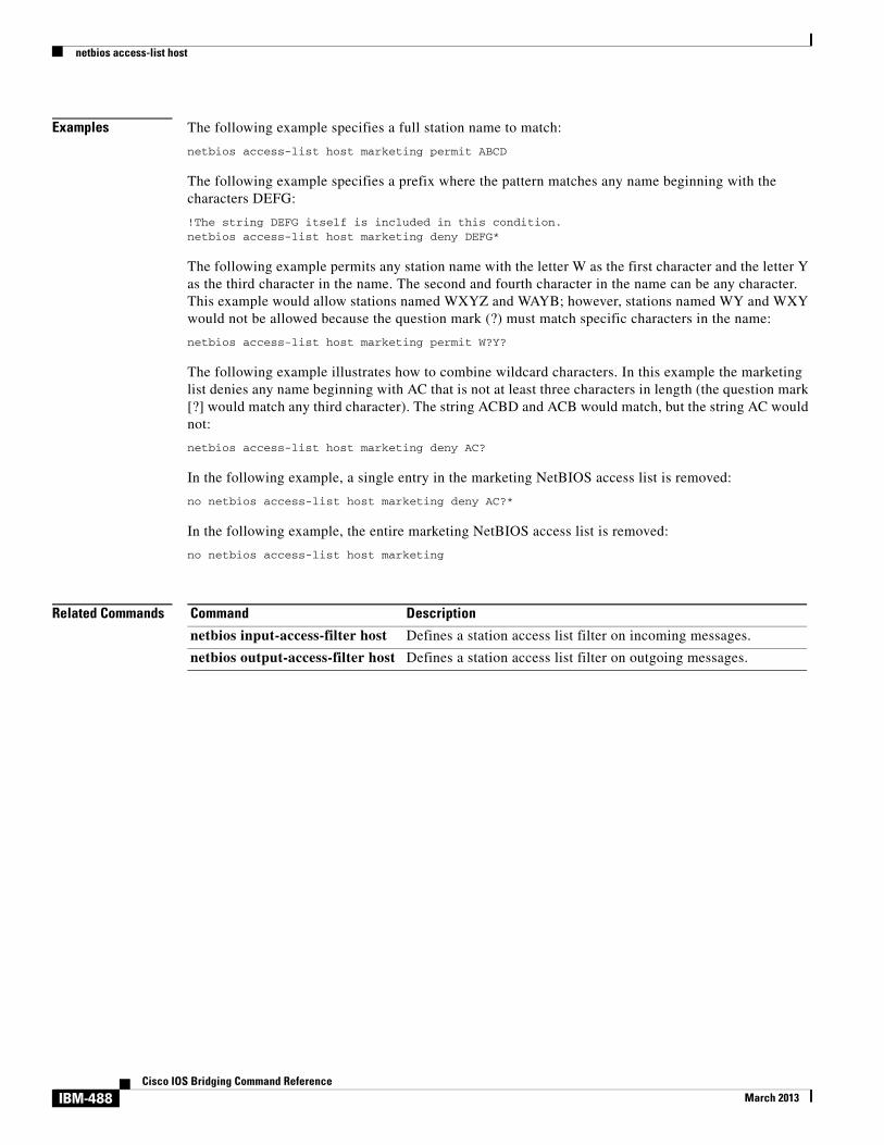
Examples The following example specifies a full station name to match:
netbios access-list host marketing permit ABCD
The following example specifies a prefix where the pattern matches any name beginning with the characters DEFG:
!The string DEFG itself is included in this condition.netbios access-list host marketing deny DEFG*
The following example permits any station name with the letter W as the first character and the letter Y as the third character in the name. The second and fourth character in the name can be any character. This example would allow stations named WXYZ and WAYB; however, stations named WY and WXY would not be allowed because the question mark (?) must match specific characters in the name:
netbios access-list host marketing permit W?Y?
The following example illustrates how to combine wildcard characters. In this example the marketing list denies any name beginning with AC that is not at least three characters in length (the question mark [?] would match any third character). The string ACBD and ACB would match, but the string AC would not:
netbios access-list host marketing deny AC?
In the following example, a single entry in the marketing NetBIOS access list is removed:
no netbios access-list host marketing deny AC?*
In the following example, the entire marketing NetBIOS access list is removed:
no netbios access-list host marketing
Related Commands Command Description
netbios input-access-filter host Defines a station access list filter on incoming messages.
netbios output-access-filter host Defines a station access list filter on outgoing messages.
IBM-488Cisco IOS Bridging Command Reference
March 2013

netbios enable-name-cache
netbios enable-name-cacheTo enable NetBIOS name caching, use the netbios enable-name-cache command in interface configuration mode. To disable the name-cache behavior, use the no form of this command.
netbios enable-name-cache
no netbios enable-name-cache
Syntax Description This command has no arguments or keywords.
Defaults Disabled
Command Modes Interface configuration
Command History
Usage Guidelines This command enables the NetBIOS name cache on the specified interface. By default the name cache is disabled for the interface. Proxy explorers must be enabled on any interface that is using the NetBIOS name cache.
Examples The following example enables NetBIOS name caching for Token Ring interface 0:
interface tokenring 0 source-bridge proxy-explorer netbios enable-name-cache
Related Commands
Release Modification
10.0 This command was introduced.
12.2(33)SRA This command was integrated into Cisco IOS Release 12.2(33)SRA.
12.2SX This command is supported in the Cisco IOS Release 12.2SX train. Support in a specific 12.2SX release of this train depends on your feature set, platform, and platform hardware.
Command Description
clear netbios-cache Clears the entries of all dynamically learned NetBIOS names.
netbios name-cache timeout Enables NetBIOS name caching and sets the time that entries can remain in the NetBIOS name cache.
show netbios-cache Displays a list of NetBIOS cache entries.
IBM-489Cisco IOS Bridging Command Reference
March 2013

netbios input-access-filter bytes
netbios input-access-filter bytesTo define a byte access list filter on incoming messages, use the netbios input-access-filter bytes command in interface configuration mode. The actual access filter byte offsets and patterns used are defined in one or more netbios-access-list bytes commands. To remove the entire access list, use the no form of this command with the appropriate name.
netbios input-access-filter bytes name
no netbios input-access-filter bytes name
Syntax Description
Defaults No access list is defined.
Command Modes Interface configuration
Command History
Examples The following example applies a previously defined filter named marketing to packets coming into Token Ring interface 1:
interface tokenring 1 netbios input-access-filter bytes marketing
Related Commands
name Name of a NetBIOS access filter previously defined with one or more of the netbios access-list bytes global configuration commands.
Release Modification
10.0 This command was introduced.
12.2(33)SRA This command was integrated into Cisco IOS Release 12.2(33)SRA.
12.2SX This command is supported in the Cisco IOS Release 12.2SX train. Support in a specific 12.2SX release of this train depends on your feature set, platform, and platform hardware.
Command Description
netbios access-list bytes Defines the offset and hexadecimal patterns with which to match byte offsets in NetBIOS packets.
IBM-490Cisco IOS Bridging Command Reference
March 2013

netbios input-access-filter host
netbios input-access-filter hostTo define a station access list filter on incoming messages, use the netbios input-access-filter host command in interface configuration mode. To remove the entire access list, use the no form of this command with the appropriate argument.
netbios input-access-filter host name
no netbios input-access-filter host name
Syntax Description
Defaults No access list is defined.
Command Modes Interface configuration
Command History
Usage Guidelines The access lists of station names are defined in netbios access-list host commands.
Examples The following example filters packets coming into Token Ring interface 1 using the NetBIOS access list named marketing:
interface tokenring 1 netbios access-list host marketing permit W?Y? netbios input-access-filter host marketing
Related Commands
name Name of a NetBIOS access filter previously defined with one or more of the netbios access-list host global configuration commands.
Release Modification
10.0 This command was introduced.
12.2(33)SRA This command was integrated into Cisco IOS Release 12.2(33)SRA.
12.2SX This command is supported in the Cisco IOS Release 12.2SX train. Support in a specific 12.2SX release of this train depends on your feature set, platform, and platform hardware.
Command Description
netbios access-list host Assigns the name of the access list to a station or set of stations on the network.
netbios output-access-filter host Defines a station access list filter on outgoing messages.
IBM-491Cisco IOS Bridging Command Reference
March 2013

netbios name-cache
netbios name-cacheTo define a static NetBIOS name cache entry, tying the server with the name netbios-name to the mac-address, and specifying that the server is accessible either locally through the interface-name specified, or remotely, through the ring-group group-number specified, use the netbios name-cache command in global configuration mode. To remove the entry, use the no form of this command.
netbios name-cache mac-address netbios-name {interface-name intetrface-number | ring-group group-number}
no netbios name-cache mac-address netbios-name
Syntax Description
Defaults No entry is defined.
Command Modes Global configuration
Command History
Usage Guidelines To specify an entry in the static name cache, first specify a Routing Information Field (RIF) that leads to the server’s MAC address. The Cisco IOS software displays an error message if it cannot find a static RIF entry for the server when the NetBIOS name-cache entry is attempted or if the server’s type conflicts with that given for the static RIF entry.
Note The names are case sensitive; therefore “Cc” is not the same as “cC.”
mac-address The MAC address.
netbios-name Server name linked to the MAC address.
interface-name Name of the interface by which the server is accessible locally.
interface-umber Number of the interface by which the server is accessible locally.
ring-group Specifies that the link is accessible remotely.
group-number Number of the ring group by which the server is accessible remotely. This ring group number must match the number you have specified with the source-bridge ring-group command. The valid range is from 1 to 4095.
Release Modification
10.0 This command was introduced.
12.2(33)SRA This command was integrated into Cisco IOS Release 12.2(33)SRA.
12.2SX This command is supported in the Cisco IOS Release 12.2SX train. Support in a specific 12.2SX release of this train depends on your feature set, platform, and platform hardware.
IBM-492Cisco IOS Bridging Command Reference
March 2013

netbios name-cache
Examples The following example indicates the syntax usage of this command if the NetBIOS server is accessed locally:
source-bridge ring-group 2 rif 0220.3333.4444 00c8.042.0060 tokenring 0 netbios name-cache 0220.3333.4444 DEF tokenring 0
The following example indicates the syntax usage of this command if the NetBIOS server is accessed remotely:
source-bridge ring-group 2 rif 0110.2222.3333 0630.021.0030 ring group 2 netbios name-cache 0110.2222.3333 DEF ring-group 2
Related Commands Command Description
show netbios-cache Displays a list of NetBIOS cache entries.
IBM-493Cisco IOS Bridging Command Reference
March 2013

netbios name-cache name-len
netbios name-cache name-lenTo specify how many characters of the NetBIOS type name the name cache will validate, use the netbios name-cache name-len command in global configuration mode.
netbios name-cache name-len length
no netbios name-cache name-len length
Syntax Description
Defaults 15 characters
Command Modes Global configuration
Command History
Examples The following example specifies that the name cache will validate 16 characters of the NetBIOS type name:
netbios name-cache name-len 16
Related Commands
length Length of the NetBIOS type name. The range is from 8 to 16 characters.
Release Modification
10.0 This command was introduced.
12.2(33)SRA This command was integrated into Cisco IOS Release 12.2(33)SRA.
12.2SX This command is supported in the Cisco IOS Release 12.2SX train. Support in a specific 12.2SX release of this train depends on your feature set, platform, and platform hardware.
Command Description
netbios enable-name-cache Enables NetBIOS name caching.
netbios name-cache Defines a static NetBIOS name cache entry.
netbios name-cache proxy-datagram Enables the Cisco IOS software to act as a proxy and send NetBIOS datagram type frames.
netbios name-cache query-timeout Specifies the “dead” time, in seconds, that starts when a host sends any ADD_NAME_QUERY, ADD_GROUP_NAME, or STATUS_QUERY frame. During this dead time, the Cisco IOS software drops any repeat, duplicate ADD_NAME_QUERY, ADD_GROUP_NAME, or STATUS_QUERY frame sent by the same host. This timeout is only effective at the time of the login negotiation process.
IBM-494Cisco IOS Bridging Command Reference
March 2013
netbios name-cache name-len
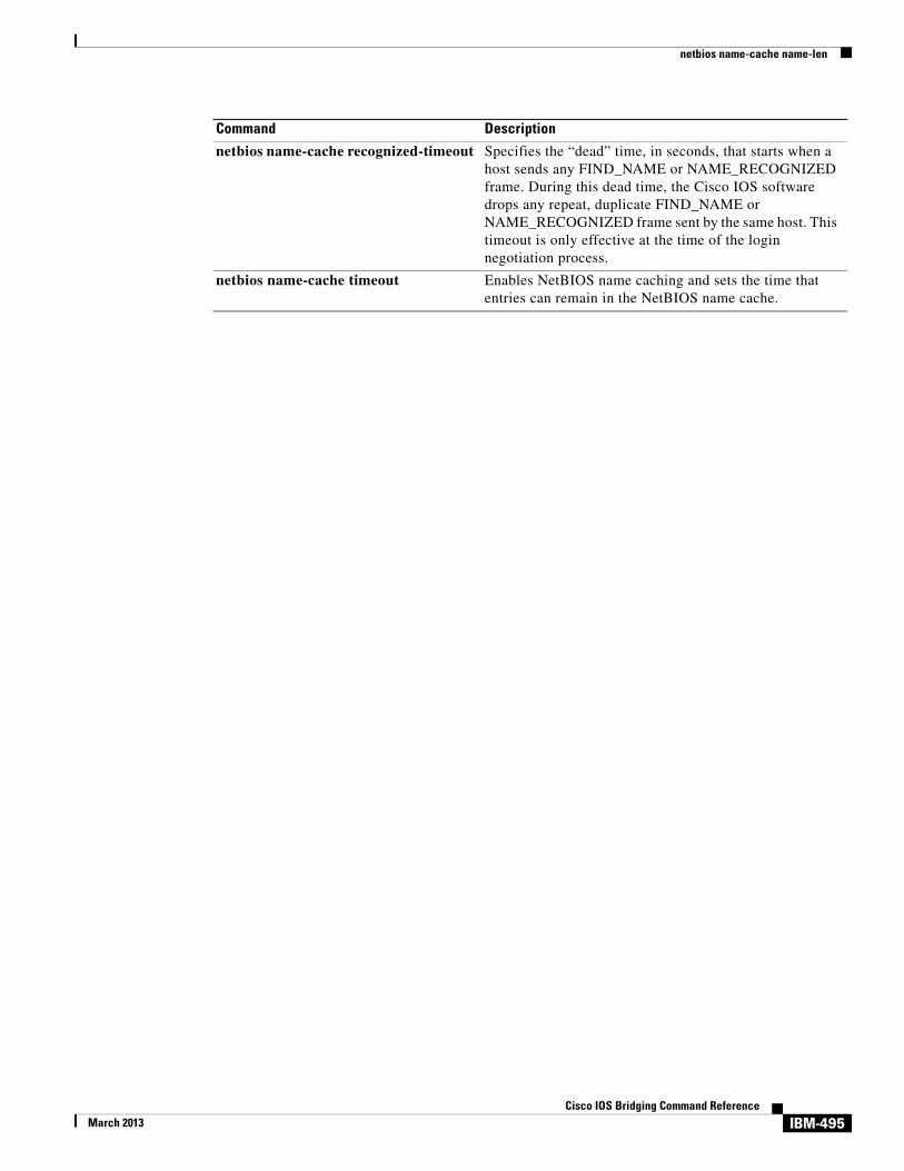
netbios name-cache recognized-timeout Specifies the “dead” time, in seconds, that starts when a host sends any FIND_NAME or NAME_RECOGNIZED frame. During this dead time, the Cisco IOS software drops any repeat, duplicate FIND_NAME or NAME_RECOGNIZED frame sent by the same host. This timeout is only effective at the time of the login negotiation process.
netbios name-cache timeout Enables NetBIOS name caching and sets the time that entries can remain in the NetBIOS name cache.
Command Description
IBM-495Cisco IOS Bridging Command Reference
March 2013

netbios name-cache proxy-datagram
netbios name-cache proxy-datagramTo enable the Cisco IOS software to act as a proxy and send NetBIOS datagram type frames, use the netbios name-cache proxy-datagram command in global configuration mode. To return to the default value, use the no form of this command.
netbios name-cache proxy-datagram seconds
no netbios name-cache proxy-datagram seconds
Syntax Description
Defaults There is no default time interval.
Command Modes Global configuration
Command History
Examples The following example specifies that the software will forward a NetBIOS datagram type frame in 20-second intervals:
netbios name-cache proxy-datagram 20
Related Commands
seconds Time interval, in seconds, that the software forwards a route broadcast datagram type packet. The valid range is any number greater than 0.
Release Modification
10.0 This command was introduced.
12.2(33)SRA This command was integrated into Cisco IOS Release 12.2(33)SRA.
12.2SX This command is supported in the Cisco IOS Release 12.2SX train. Support in a specific 12.2SX release of this train depends on your feature set, platform, and platform hardware.
Command Description
netbios enable-name-cache Enables NetBIOS name caching.
netbios name-cache Defines a static NetBIOS name cache entry, tying the server with the name netbios-name to the mac-address, and specifying that the server is accessible either locally through the interface-name specified, or remotely through the ring-group group-number specified.
IBM-496Cisco IOS Bridging Command Reference
March 2013

netbios name-cache proxy-datagram
netbios name-cache query-timeout Specifies the “dead” time, in seconds, that starts when a host sends any ADD_NAME_QUERY, ADD_GROUP_NAME, or STATUS_QUERY frame. During this dead time, the Cisco IOS software drops any repeat, duplicate ADD_NAME_QUERY, ADD_GROUP_NAME, or STATUS_QUERY frame sent by the same host. This timeout is only effective at the time of the login negotiation process.
netbios name-cache recognized-timeout Specifies the “dead” time, in seconds, that starts when a host sends any FIND_NAME or NAME_RECOGNIZED frame. During this dead time, the Cisco IOS software drops any repeat, duplicate FIND_NAME or NAME_RECOGNIZED frame sent by the same host. This timeout is only effective at the time of the login negotiation process.
netbios name-cache timeout Enables NetBIOS name caching and sets the time that entries can remain in the NetBIOS name cache.
Command Description
IBM-497Cisco IOS Bridging Command Reference
March 2013

netbios name-cache query-timeout
netbios name-cache query-timeoutTo specify the “dead” time, in seconds, that starts when a host sends any ADD_NAME_QUERY, ADD_GROUP_NAME, or STATUS_QUERY frame, use the netbios name-cache query-timeout command in global configuration mode. During this dead time, the Cisco IOS software drops any repeat, duplicate ADD_NAME_QUERY, ADD_GROUP_NAME, or STATUS_QUERY frame sent by the same host. This timeout is only effective at the time of the login negotiation process. To restore the default of 6 seconds, use the no form of this command.
netbios name-cache query-timeout seconds
no netbios name-cache query-timeout
Syntax Description
Defaults 6 seconds
Command Modes Global configuration
Command History
Examples The following example sets the timeout to 15 seconds:
netbios name-cache query-timeout 15
Related Commands
seconds Dead time period in seconds. Default is 6 seconds.
Release Modification
10.0 This command was introduced.
12.2(33)SRA This command was integrated into Cisco IOS Release 12.2(33)SRA.
12.2SX This command is supported in the Cisco IOS Release 12.2SX train. Support in a specific 12.2SX release of this train depends on your feature set, platform, and platform hardware.
Command Description
netbios name-cache recognized-timeout Specifies the “dead” time, in seconds, that starts when a host sends any FIND_NAME or NAME_RECOGNIZED frame. During this dead time, the Cisco IOS software drops any repeat, duplicate FIND_NAME or NAME_RECOGNIZED frame sent by the same host. This timeout is only effective at the time of the login negotiation process.
IBM-498Cisco IOS Bridging Command Reference
March 2013

netbios name-cache recognized-timeout
netbios name-cache recognized-timeoutTo specify the “dead” time, in seconds, that starts when a host sends any FIND_NAME or NAME_RECOGNIZED frame, use the netbios name-cache recognized-timeout command in global configuration mode. During this dead time, the Cisco IOS software drops any repeat, duplicate FIND_NAME or NAME_RECOGNIZED frame sent by the same host. This timeout is effective only at the time of the login negotiation process. To restore the default of 6 seconds, use the no form of this command.
netbios name-cache recognized-timeout seconds
no netbios name-cache recognized-timeout
Syntax Description
Defaults 6 seconds
Command Modes Global configuration
Command History
Examples The following example sets the timeout to 15 seconds:
netbios name-cache recognized-timeout 15
Related Commands
seconds Dead time period in seconds. Default is 6 seconds.
Release Modification
10.0 This command was introduced.
12.2(33)SRA This command was integrated into Cisco IOS Release 12.2(33)SRA.
12.2SX This command is supported in the Cisco IOS Release 12.2SX train. Support in a specific 12.2SX release of this train depends on your feature set, platform, and platform hardware.
Command Description
netbios name-cache query-timeout Specifies the “dead” time, in seconds, that starts when a host sends any ADD_NAME_QUERY, ADD_GROUP_NAME, or STATUS_QUERY frame. During this dead time, the Cisco IOS software drops any repeat, duplicate ADD_NAME_QUERY, ADD_GROUP_NAME, or STATUS_QUERY frame sent by the same host. This timeout is only effective at the time of the login negotiation process.
IBM-499Cisco IOS Bridging Command Reference
March 2013

netbios name-cache timeout
netbios name-cache timeoutTo enable NetBIOS name caching and to set the time that entries can remain in the NetBIOS name cache, use the netbios name-cache timeout command in global configuration mode. To restore the default of 15 minutes, use the no form of this command.
netbios name-cache timeout minutes
no netbios name-cache timeout minutes
Syntax Description
Defaults 15 minutes
Command Modes Global configuration
Command History
Usage Guidelines This command allows you to establish NetBIOS name caching. NetBIOS name-caching does not apply to static entries. Once the time expires, the entry will be deleted from the cache.
Examples The following example sets the timeout to 10 minutes:
interface tokenring 0 netbios name-cache timeout 10
Related Commands
minutes Time, in minutes, that entries can remain in the NetBIOS name cache. Default is 15 minutes.
Release Modification
10.0 This command was introduced.
12.2(33)SRA This command was integrated into Cisco IOS Release 12.2(33)SRA.
12.2SX This command is supported in the Cisco IOS Release 12.2SX train. Support in a specific 12.2SX release of this train depends on your feature set, platform, and platform hardware.
Command Description
show netbios-cache Displays a list of NetBIOS cache entries.
IBM-500Cisco IOS Bridging Command Reference
March 2013
netbios output-access-filter bytes
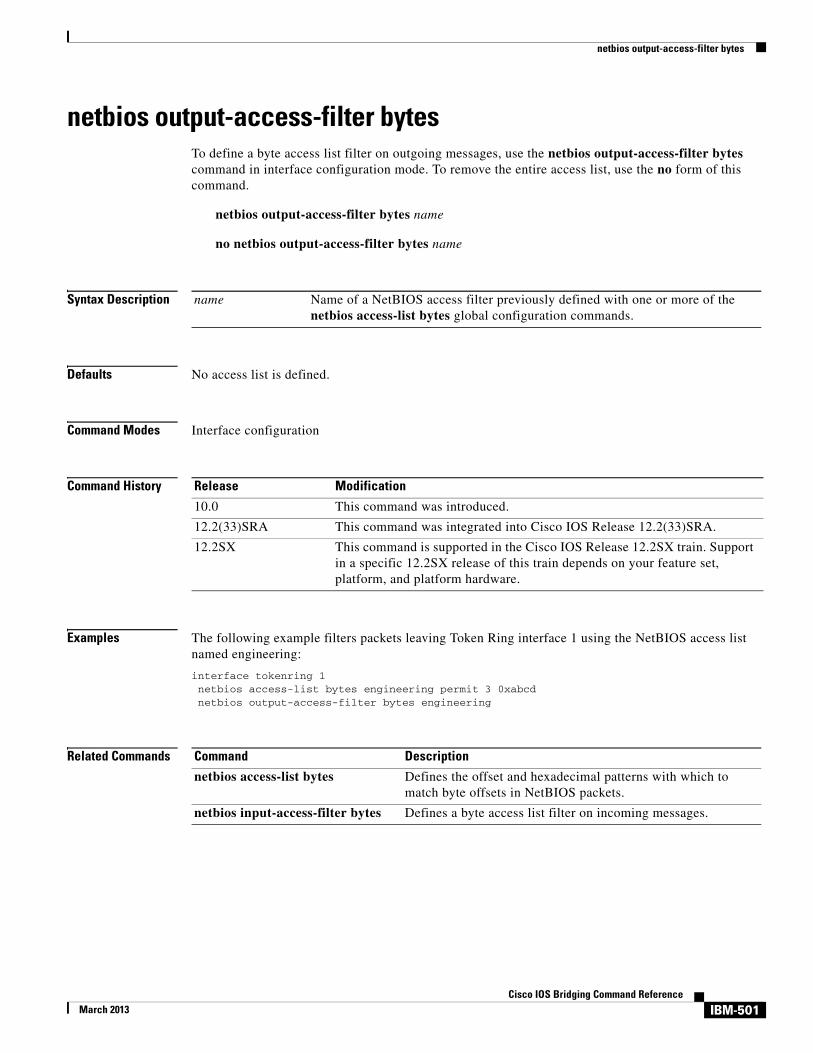
netbios output-access-filter bytesTo define a byte access list filter on outgoing messages, use the netbios output-access-filter bytes command in interface configuration mode. To remove the entire access list, use the no form of this command.
netbios output-access-filter bytes name
no netbios output-access-filter bytes name
Syntax Description
Defaults No access list is defined.
Command Modes Interface configuration
Command History
Examples The following example filters packets leaving Token Ring interface 1 using the NetBIOS access list named engineering:
interface tokenring 1 netbios access-list bytes engineering permit 3 0xabcd netbios output-access-filter bytes engineering
Related Commands
name Name of a NetBIOS access filter previously defined with one or more of the netbios access-list bytes global configuration commands.
Release Modification
10.0 This command was introduced.
12.2(33)SRA This command was integrated into Cisco IOS Release 12.2(33)SRA.
12.2SX This command is supported in the Cisco IOS Release 12.2SX train. Support in a specific 12.2SX release of this train depends on your feature set, platform, and platform hardware.
Command Description
netbios access-list bytes Defines the offset and hexadecimal patterns with which to match byte offsets in NetBIOS packets.
netbios input-access-filter bytes Defines a byte access list filter on incoming messages.
IBM-501Cisco IOS Bridging Command Reference
March 2013

netbios output-access-filter host
netbios output-access-filter hostTo define a station access list filter on outgoing messages, use the netbios output-access-filter host command in interface configuration mode. To remove the entire access list, use the no form of this command.
netbios output-access-filter host name
no netbios output-access-filter host name
Syntax Description
Defaults No access list filter is defined.
Command Modes Interface configuration
Command History
Examples The following example filters packets leaving Token Ring interface 1 using the NetBIOS access list named engineering:
interface tokenring 1 netbios access-list host engineering permit W?Y? netbios output-access-filter host engineering
Related Commands
name Name of a NetBIOS access filter previously defined with one or more of the netbios access-list host global configuration commands.
Release Modification
10.0 This command was introduced.
12.2(33)SRA This command was integrated into Cisco IOS Release 12.2(33)SRA.
12.2SX This command is supported in the Cisco IOS Release 12.2SX train. Support in a specific 12.2SX release of this train depends on your feature set, platform, and platform hardware.
Command Description
netbios access-list host Assigns the name of the access list to a station or set of stations on the network.
netbios input-access-filter host Defines a station access list filter on incoming messages.
IBM-502Cisco IOS Bridging Command Reference
March 2013

offload (backup)
offload (backup)To configure a backup group of offload devices, use the offload command in IP host backup configuration mode. To cancel the offload task on the Cisco Mainframe Channel Connection (CMCC) adapter, use the no form of this command.
offload device-address ip-address host-name device-name host-ip-link device-ip-link host-api-link device-api-link [broadcast]
no offload path device-address
Syntax Description
Defaults No default behavior or values
Command Modes IP host backup configuration
device-address Hexadecimal value in the range from 0000 to FFFF. This value specifies the logical channel path and consists of two digits for the physical connection (either on the host or on the ESCON director), one digit for the channel logical address, and one digit for the control unit logical address. If the path is not specified in the input/output configuration program (IOCP), the default value for channel logical address and control unit logical address is 0.
ip-address Hexadecimal value in the range from 00 to FE. This is the unit address associated with the control unit number and path as specified in the host IOCP file. The device address must have an even-numbered value.
host-name Host name specified in the device statement in the host TCP/IP application configuration file.
device-name Common Link Access for Workstations (CLAW) workstation name specified in the device statement in the host TCP/IP application configuration file.
host-ip-link Host link name for the IP link as specified by the host application. For IBM virtual machine (VM) and Multiple Virtual Systems (MVS) TCP/IP stacks, this value is tcpip. When used with other applications, this value must match the value coded in the host application.
device-ip-link Workstation link name for the IP link as specified by the host application. For IBM VM and MVS TCP/IP stacks, this value is tcpip. When used with other applications, this value must match the value coded in the host application.
host-api-link Host link name for the application program interface (API) link as specified by the host application. For IBM VM and MVS TCP/IP stacks, this value is tcpip. When used with other applications, this value must match the value coded in the host application.
device-api-link Offload link name for the API link as specified by the host application. For IBM VM and MVS TCP/IP stacks, this value is api. When used with other applications, this value must match the value coded in the host application.
broadcast (Optional) Enables broadcast processing for this subchannel.
IBM-503Cisco IOS Bridging Command Reference
March 2013

offload (backup)
Command History
Usage Guidelines Along with the path command, the offload backup command provides a quick way to configure an offload backup group.
Offload devices provide IP connectivity to a mainframe while offloading a large part of the TCP/IP processing to the CMCC adapter. Not every mainframe TCP/IP stack supports offload.
The offload command in IP host backup configuration mode uses the same underlying configuration parameters as the claw command in IP host backup configuration mode.
Examples The following examples show two methods for entering the same IP host backup group information. The first group of commands is the long form, using the offload interface configuration command. The second group is the shortcut, using the path interface configuration command and an offload IP host backup configuration command.
Long form:
offload c000 00 10.92.10.5 sysa router1 tcpip tcpip tcpip api backupoffload c100 00 10.92.10.5 sysa router1 tcpip tcpip tcpip api backupoffload c200 00 10.92.10.5 sysa router1 tcpip tcpip tcpip api backup
Shortcut form:
path c000 c100 c200offload 00 10.92.10.5 sysa router1 tcpip tcpip tcpip api
Related Commands
Release Modification
12.0 This command was introduced.
12.2(33)SRA This command was integrated into Cisco IOS Release 12.2(33)SRA.
12.2SX This command is supported in the Cisco IOS Release 12.2SX train. Support in a specific 12.2SX release of this train depends on your feature set, platform, and platform hardware.
Command Description
show extended channel ip-stack Displays information about the IP stack running on CMCC channel interfaces.
show extended channel statistics Displays statistical information about subchannels on the physical interface of a CMCC adapter and displays information that is specific to the interface channel devices. The information generally is useful only for diagnostic tasks performed by technical support personnel.
show extended channel subchannel Displays information about the CMCC adapter physical interfaces and displays information that is specific to the interface channel connection. The information displayed generally is useful only for diagnostic tasks performed by technical support personnel.
show extended channel tcp-connections Displays information about the TCP sockets on a channel interface.
IBM-504Cisco IOS Bridging Command Reference
March 2013

offload (backup)
show extended channel tcp-stack Displays information about the TCP stack running on CMCC adapter interfaces.
offload (primary) (primary) Configures an Offload device (read and write subchannel) for communication with a mainframe TCP/IP stack in offload mode and also configures individual members of an Offload backup group for the IP Host Backup feature.
security (TN3270) Displays CLAW packing names and their connection state.
Command Description
IBM-505Cisco IOS Bridging Command Reference
March 2013

offload (primary)
offload (primary)To configure an offload device (read and write subchannel) for communication with a mainframe TCP/IP stack in offload mode and configure individual members of an offload backup group for the IP Host Backup feature, use the offload command in interface configuration mode. To cancel the offload task on the Cisco Mainframe Channel Connection (CMCC) adapter, use the no form of this command.
offload path device-address ip-address host-name device-name host-ip-link device-ip-link host-api-link device-api-link [broadcast] [backup]
no offload path device-address
Syntax Description
Defaults No default behavior or values
path Hexadecimal value in the range from 0000 to FFFF. This value specifies the logical channel path and consists of two digits for the physical connection (either on the host or on the ESCON director), one digit for the channel logical address, and one digit for the control unit logical address. If the path is not specified in the input/output configuration program (IOCP), the default value for channel logical address and control unit logical address is 0.
device-address Hexadecimal value in the range from 00 to FE. This is the unit address associated with the control unit number and path as specified in the host IOCP file. The device address must have an even-numbered value.
ip-address IP address specified in the host TCP/IP application configuration file.
host-name Host name specified in the device statement in the host TCP/IP application configuration file.
device-name Common Link Access for Workstations (CLAW) workstation name specified in the device statement in the host TCP/IP application configuration file.
host-ip-link Common Link Access for Workstations (CLAW) host link name for the IP link as specified by the host application. For IBM virtual machine (VM) and VMS TCP/IP stacks, this value is tcpip. When used with other applications, this value must match the value coded in the host application.
device-ip-link CLAW workstation link name for the IP link as specified by the host application. For IBM VM and MVS TCP/IP stacks, this value is tcpip. When used with other applications, this value must match the value coded in the host application.
host-api-link CLAW host link name for the application program interface (API) link as specified by the host application. For IBM VM and MVS TCP/IP stacks, this value is tcpip. When used with other applications, this value must match the value coded in the host application.
device-api-link Offload link name for the API link as specified by the host application. For IBM VM and MVS TCP/IP stacks, this value is api. When used with other applications, this value must match the value coded in the host application.
broadcast (Optional) Enables broadcast processing for this subchannel.
backup (Optional) Enables this offload connection to be used as part of a backup group of offload connections for the specified IP address.
IBM-506Cisco IOS Bridging Command Reference
March 2013

offload (primary)
Command Modes Interface configuration
Command History
Usage Guidelines Offload devices provide IP connectivity to a mainframe while offloading a large part of the TCP/IP processing to the CMCC adapter. Not every mainframe TCP/IP stack supports offload.
The offload command uses the same underlying configuration parameters as does the claw command.
Examples The following example shows how to enable IBM channel attach offload processing on a CMCC adapter’s physical channel interface that is supporting a directly connected ESCON channel:
interface channel 3/0ip address 10.92.0.1 255.255.255.0offload 0100 00 10.92.0.21 CISCOVM EVAL TCPIP TCPIP TCPIP API
The following example shows how an IP host backup group is specified using the backup keyword:
interface Channel3/0 no ip address no keepalive shutdown offload 0100 C0 10.30.1.2 TCPIP OS2TCP TCPIP TCPIP TCPIP API backup offload 0110 C0 10.30.1.2 TCPIP OS2TCP TCPIP TCPIP TCPIP API backup offload 0120 C0 10.30.1.2 TCPIP OS2TCP TCPIP TCPIP TCPIP API backup offload 0110 C2 10.30.1.3 TCPIP OS2TCP TCPIP TCPIP TCPIP API
Related Commands
Release Modification
11.0 This command was introduced.
12.0 The backup keyword was added.
12.2(33)SRA This command was integrated into Cisco IOS Release 12.2(33)SRA.
12.2SX This command is supported in the Cisco IOS Release 12.2SX train. Support in a specific 12.2SX release of this train depends on your feature set, platform, and platform hardware.
Command Description
offload (backup) Configures a backup group of Offload devices.
security (TN3270) Displays CLAW packing names and their connection state.
show extended channel ip-stack Displays information about the IP stack running on CMCC channel interfaces.
show extended channel statistics Displays statistical information about subchannels on the physical interface of a CMCC adapter and displays information that is specific to the interface channel devices. The information generally is useful only for diagnostic tasks performed by technical support personnel.
show extended channel subchannel Displays information about the CMCC adapter physical interfaces and displays information that is specific to the interface channel connection. The information displayed generally is useful only for diagnostic tasks performed by technical support personnel.
IBM-507Cisco IOS Bridging Command Reference
March 2013

offload (primary)
show extended channel tcp-connections
Displays information about the TCP sockets on a channel interface.
show extended channel tcp-stack Displays information about the TCP stack running on CMCC adapter interfaces.
show extended channel udp-listeners
Displays information about the UDP listener sockets running on the CMCC adapter interfaces.
show extended channel udp-stack Displays information about the UDP stack running on the CMCC adapter interfaces.
Command Description
IBM-508Cisco IOS Bridging Command Reference
March 2013
offload alias
offload aliasTo assign a virtual IP address to a real IP address for an offload device on a Cisco Mainframe Channel Connection (CMCC) adapter, use the offload alias command in interface configuration mode. To remove the alias IP address, use the no form of this command.
offload alias real-ip alias-ip
no offload alias real-ip alias-ip
Syntax Description
Defaults No default behavior or values
Command Modes Interface configuration
Command History
Usage Guidelines Configure the offload alias command after you configure TCP/IP offload support on a CMCC adapter.
You can configure up to 8 different alias IP addresses for each real IP address of an offload device. You can assign the same alias IP address to multiple real IP addresses.
Examples The following example configures TCP/IP offload support on a CMCC adapter for a host located at real IP address 10.10.21.3 with an alias IP address of 10.2.33.88:
interface channel 3/1 offload E180 80 10.10.21.3 IPCLUST IPCLUST TCPIP TCPIP TCPIP API offload alias 10.10.21.3 10.2.33.88
real-ip Real IP address of the offload-supported device.
alias-ip Virtual IP address for the offload-supported device.
Release Modification
12.0(7)T This command was introduced.
12.2(33)SRA This command was integrated into Cisco IOS Release 12.2(33)SRA.
12.2SX This command is supported in the Cisco IOS Release 12.2SX train. Support in a specific 12.2SX release of this train depends on your feature set, platform, and platform hardware.
IBM-509Cisco IOS Bridging Command Reference
March 2013

path
path
To specify one or more data paths for the IP host backup, use the path command in interface configuration mode. To delete a single path, use the no form of this command.
path path
no path path
Syntax Description
Defaults No default behavior or values
Command Modes Interface configuration
Command History
Usage Guidelines Up to 16 values for the path argument can be specified in the path command.
The path command places the router in IP host backup configuration mode, where additional commands can be entered to define backup groups for Common Link Access for Workstations (CLAW) and offload connections.
Command Description
name (primary) Configures an Offload device (read and write subchannel) for communication with a mainframe TCP/IP stack in offload mode and also configures individual members of an Offload backup group for the IP Host Backup feature.
show extended channel icmp-stack Displays information about the ICMP stack running on the CMCC channel interfaces.
show extended channel ip-stack Displays information about the IP stack running on CMCC channel interfaces.
path Hexadecimal value in the range from 0000 to FFFF. This value specifies the logical channel path and consists of two digits for the physical connection (either on the host or on the ESCON director), one digit for the channel logical address, and one digit for the control unit logical address. If the path is not specified in the input/output configuration program (IOCP), the default values for channel logical address and control unit logical address is 0. Up to 16 values for the path argument can be specified in the path command.
Release Modification
12.0 This command was introduced.
12.2(33)SRA This command was integrated into Cisco IOS Release 12.2(33)SRA.
12.2SX This command is supported in the Cisco IOS Release 12.2SX train. Support in a specific 12.2SX release of this train depends on your feature set, platform, and platform hardware.
IBM-510Cisco IOS Bridging Command Reference
March 2013

path
Examples The following examples show two methods for entering the same IP host backup group information. The first group is the long form, using the offload command in interface configuration mode. The second group of commands is the shortcut, using the path interface configuration command and an offload IP host backup configuration command.
Long form:
offload c000 00 198.92.10.5 sysa router1 tcpip tcpip backupoffload c100 00 198.92.10.5 sysa router1 tcpip tcpip backupoffload c200 00 198.92.10.5 sysa router1 tcpip tcpip backup
Shortcut form:
path c000 c100 c200offload 00 198.92.10.5 sysa router1 tcpip tcpip
Related Commands Command Description
claw (backup) Configures a CLAW device (read and write subchannel) for communication with a mainframe TCP/IP stack in offload mode and also configures individual members of a CLAW backup group for the IP Host Backup feature.
offload (backup) Configures a backup group of Offload devices.
IBM-511Cisco IOS Bridging Command Reference
March 2013
ping sna
ping snaTo initiate an Advanced Program-to-Program Communication (APPC) session with a named destination logical unit (LU) to run the APING transaction program to check network integrity and timing characteristics, use the ping sna command in privileged EXEC mode.
ping sna [-1] [-c consecutive-packets] [-i number-iterations] [-m mode] [-n] [-r] [-s size] [-t tpname] [-u userid -p password] destination
Syntax Description
Defaults If -1 is not specified, the ping sna command will send the quantity of data represented by the -s size, -i number-iterations, and -c consecutive blocks options. It will be first sent in the direction from the ping sna requester to the receiver, then in the opposite direction.
If -c is not specified, consecutive data blocks per iteration defaults to 1.
If -i is not specified, number of iterations defaults to 2.
If -m is not specified, the mode defaults to #INTER.
If -s is not specified, the size of each block of data transferred defaults to 100 bytes.
If -t is not specified, the default transaction program name on the receiver is APINGD.
Command Modes Privileged EXEC
-1 (Optional) Sends data from client to server only (no echo).
-c consecutive-blocks (Optional) Specifies the number of data blocks sent per iteration. The default is 1.
-i number-iterations (Optional) Specifies the number of iterations. The default is 2.
-m mode (Optional) Specifies the APPC mode to use. The default is #INTER.
-n (Optional) Omits any security (SECURITY=NONE).
-r (Optional) Displays the route taken by APPC PING.
-s size (Optional) Specifies the size of the data block to be sent. The default is 100 bytes.
-t tpname (Optional) Specifies transaction program (TP) to start on the server. The default is APINGD.
-u userid (Optional) Specifies USERID.
-p password (Optional) Specifies the password associated with the userid specified after -u. Required when -u is specified. Password must be one to eight characters in length.
destination Specifies the fully qualified name of the destination logical unit or control point with which an APING transaction should be initiated.
IBM-512Cisco IOS Bridging Command Reference
March 2013

ping sna
Command History
Usage Guidelines The ping sna command requires the destination to support the APING transaction program for the ping to succeed.
Examples The following is an example of the ping sna command contact the destination NETA.CP001:
Router# ping sna NETA.CP001
Related Commands
Release Modification
12.0(5)XN This command was introduced.
12.0(7)T This command was integrated into Cisco IOS Release 12.0(7)T.
12.2(33)SRA This command was integrated into Cisco IOS Release 12.2(33)SRA.
12.2SX This command is supported in the Cisco IOS Release 12.2SX train. Support in a specific 12.2SX release of this train depends on your feature set, platform, and platform hardware.
Command Description
show snasw session Displays the SNASw session objects.
IBM-513Cisco IOS Bridging Command Reference
March 2013

pool
poolTo define pool names for the TN3270 server and specify the number of screens and printers in each logical cluster, use the pool command in TN3270 server configuration mode. To remove a client IP pool, use the no form of this command.
pool poolname [cluster layout layout-spec-string]
no pool poolname
Syntax Description
Defaults The default value for the layout-spec-string argument is 1a.
Command Modes TN3270 server configuration
Command History
Usage Guidelines The pool and allocate lu commands enable the TN3270 server to know the relationships between screen and printer LUs. These commands are an alternative to the logical unit (LU) nailing feature that allows clients to be nailed to LUs.
The pool command is configured in the TN3270 scope. The pool command provides the pool names and the definitions of the number of screens and printers in one logical cluster. Each pool statement must have a unique pool name.
poolname Unique pool name that cannot exceed eight characters in length. Valid characters are (alphabetic characters are not case sensitive):
• First character—Alphabetic (A–Z) and national characters "@”, “#”, and “$”
• Second through eighth characters—Alphabetic (A–Z), numeric (0–9), and national characters "@”, “#”, and “$”
cluster layout layout-spec-string
(Optional) Name for the cluster and to indicate a cluster of logical unit (LU)s such as printers. The sum of the numbers must be less than or equal to 255. No spaces are used between the entries in the layout-spec-string argument. The default value is 1a.
Release Modification
11.2(18)BC This command was introduced.
12.0(5)T This command was integrated into Cisco IOS Release 12.0(5)T.
12.2(33)SRA This command was integrated into Cisco IOS Release 12.2(33)SRA.
12.2SX This command is supported in the Cisco IOS Release 12.2SX train. Support in a specific 12.2SX release of this train depends on your feature set, platform, and platform hardware.
IBM-514Cisco IOS Bridging Command Reference
March 2013
pool
The TN3270 server validates pool names when configuring a pool name and when processing the name received on a CONNECT request from the client. The TN3270 server rejects an invalid name and truncates the name received in the CONNECT request from the client to eight characters or at an invalid character (whichever comes first) when processing the CONNECT request.
When using a pool command to create a cluster, use a combination of the following values in the layout-spec-string argument:
s (screen)
p (printer)
a (any, or wildcard) (refers to a printer or a screen)
Examples Use the following format to define the layout-spec-string argument, where the decimal-num argument is a decimal number from 1 to 255:
pool poolname cluster layout {decimal-nums}{decimal-nump}{decimal-numa}
The total sum of the numbers must be less than or equal to 255. No spaces are used between the entries in the layout-spec-string argument. The default is 1a, which defines one screen or one printer. A screen, printer, or a wildcard definition cannot be followed by a definition of the same type. A screen definition can be followed only by a printer or wildcard. Similarly, a printer definition can be followed only by a wildcard or a screen definition.
The following are examples of invalid layout-spec-string values, and the corresponding corrected specification:
• A layout-spec-string of 3s6s is invalid. The correct specification is 9s.
• A layout-spec-string of 3s6p7a8a is invalid. The correct specification is 3s6p15a.
• A layout-spec-string of 255s10p is invalid. Although the decimal number for any portion of the layout-spec-string can be from 1 to 255, the total number across all parameters cannot exceed 255. To correct this example, you can reduce the screens to 245 as 245s10p.
The combination of a screen, printer, and wildcard constitute a group. The layout-spec-string argument can support a maximum of four groups.
Consider the following example:
pool CISCO cluster layout 2s3p4a5s6a7s8p9s
There are four groups in this definition: 2s3p4a, 5s6a, 7s8p and 9s.
Pools must be defined before any pool references under the listen points are defined. Also, pools must be defined before they are referenced by other statements in the configuration. Failure to define the pool before it is referenced will cause the referencing configuration to be rejected.
Pools that are deleted (using the no form of the command) will cause all statements referencing the pool to be deleted.
The following criteria apply to the creation of pool names and local addresses:
• Pool and LU names must be unique; they cannot be identical.
• Local address ranges for pools must not overlap.
• Local address ranges for LU pools must not overlap with the existing client nailing configuration.
• Pool configurations made while LUs are in use do not affect the current LU configuration.
The following example uses the pool command to create two pools, pcpool and unixpool:
tn3270-server
IBM-515Cisco IOS Bridging Command Reference
March 2013
pool
pool pcpool cluster layout 4s1ppool unixpool cluster layout 49s1p
listen-point 10.20.30.40client ip 10.10.10.2 pool pcpoolpu PU1 91903315 dlurallocate lu 1 pool pcpool clusters 50
pu PU2 91903345 dlurallocate lu 1 pool unixpool clusters 5
In this example, the pcpool contains a cluster of 4 screens and 1 printer per cluster. The total number of devices in a cluster cannot exceed 255, therefore the pcpool contains a total of 50 clusters with each cluster containing 5 LUs. Note that the remaining 5 LUs automatically go to the generic pool.
The unixpool contains 49 screens and 1 printer per cluster. The total number of devices in a cluster cannot exceed 255, therefore the unixpool contains a total of 5 clusters with each cluster containing 50 LUs. Again, note that the last 5 LUs automatically go to the generic pool.
Related Commands Command Description
tn3270-server Starts the TN3270 server on a CMCC adapter and enters TN3270 server configuration mode.
IBM-516Cisco IOS Bridging Command Reference
March 2013

ppp bcp tagged-frame
ppp bcp tagged-frameTo enable the negotiation of IEEE 802.1Q-tagged packets over PPP links, use the ppp bcp tagged-frame command in interface configuration mode. To disable the negotiation of IEEE 802.1Q-tagged packets over PPP links, use the no form of this command.
ppp bcp tagged-frame
no ppp bcp tagged-frame
Syntax Description This command has no arguments or keywords.
Defaults The ppp bcp tagged-frame command is enabled by default.
Command Modes Interface configuration
Command History
Usage Guidelines This command provides flexibility in specifying which Bridge Control Protocol (BCP) options will be negotiated with the peer.
Examples The following example configures Ethernet interface 0 to bridge packets using VLAN ID 100, and assigns the interface to bridge group 1:
interface serial 4/0 ppp bcp tagged-frame
Release Modification
12.3(4)T This command was introduced.
12.2SX This command is supported in the Cisco IOS Release 12.2SX train. Support in a specific 12.2SX release of this train depends on your feature set, platform, and platform hardware.
IBM-517Cisco IOS Bridging Command Reference
March 2013
preferred-nnserver
preferred-nnserverTo specify a preferred network node (NN) as server, use the preferred-nnserver command in Dependent Logical Unit Requestor (DLUR) configuration mode. To remove the preference, use the no form of this command.
preferred-nnserver name
no preferred-nnserver
Syntax Description
Defaults No default behavior or values
Command Modes DLUR configuration
Command History
Usage Guidelines The preferred-nnserver command is valid only on the virtual channel interface. Fully qualified names consist of two case-insensitive alphanumeric strings, separated by a period. However, for compatibility with existing Advanced Peer-to-Peer Networking (APPN) products, including virtual telecommunications access method (VTAM), the characters “#” (pound), “@” (at), and “$” (dollar) are allowed in the fully qualified name strings. Each string is from one to 8 characters long; for example, RA12.NODM1PP. The portion of the name before the period is the network entity title (NET) ID and is shared between entities in the same logical network.
When no preferred server is specified, the Dependent Logical Unit Requestor (DLUR) will request NN server support from the first suitable node with which it makes contact. If refused, it will try the next one, and so on.
If a preferred server is specified, then DLUR will wait a short time to allow a link to the preferred server to materialize. If the preferred server is not found in that time, any suitable node can be used.
DLUR will not relinquish the current NN server merely because the preferred server becomes available.
Examples The following example selects SYD.VMX as the preferred NN server:
preferred-nnserver SYD.VMX
name Fully qualified name of an NN.
Release Modification
11.2 This command was introduced.
12.2(33)SRA This command was integrated into Cisco IOS Release 12.2(33)SRA.
12.2SX This command is supported in the Cisco IOS Release 12.2SX train. Support in a specific 12.2SX release of this train depends on your feature set, platform, and platform hardware.
IBM-518Cisco IOS Bridging Command Reference
March 2013

preferred-nnserver
Related Commands Command Description
client pool Nails clients to pools.
IBM-519Cisco IOS Bridging Command Reference
March 2013

priority-list protocol bstun
priority-list protocol bstunTo establish block serial tunnel (BSTUN) queueing priorities based on the BSTUN header, use the priority-list protocol bstun command in global configuration mode. To revert to normal priorities, use the no form of this command.
priority-list list-number protocol bstun queue [gt | lt packetsize] [address bstun-group bsc-addr]
no priority-list list-number protocol bstun queue [gt | lt packetsize] [address bstun-group bsc-addr]
Syntax Description
Defaults Prioritize based on BSTUN header.
Command Modes Global configuration
Command History
Examples In the following example, the output interface examines the header information and places packets with the BSTUN header on the output queue specified as medium:
priority-list 1 protocol bstun medium
Related Commands
list-number Arbitrary integer from 1 to 10 that identifies the priority list selected by the user.
queue Priority queue type: high, medium, normal, or low.
gt | lt packetsize (Optional) Output interface examines header information and packet size and places packets with the BSTUN header that match criteria (gt or lt specified packet size) on specified output.
address bstun-group bsc-addr (Optional) Output interface examines header information and Bisync address and places packets with the BSTUN header that match Bisync address on the specified output queue.
Release Modification
11.0 This command was introduced.
12.2(33)SRA This command was integrated into Cisco IOS Release 12.2(33)SRA.
12.2SX This command is supported in the Cisco IOS Release 12.2SX train. Support in a specific 12.2SX release of this train depends on your feature set, platform, and platform hardware.
Command Description
encapsulation bstun Configures BSTUN on a particular serial interface.
IBM-520Cisco IOS Bridging Command Reference
March 2013

priority-list protocol ip tcp
priority-list protocol ip tcpTo establish block serial tunnel (BSTUN) or serial tunnel (STUN) queueing priorities based on the TCP port, use the priority-list protocol ip tcp command in global configuration mode. To revert to normal priorities, use the no form of this command.
priority-list list-number protocol ip queue tcp tcp-port-number
no priority-list list-number protocol ip queue tcp tcp-port-number
Syntax Description
Defaults The default queue value is normal.
Command Modes Global configuration
Command History
Usage Guidelines Use the priority-list protocol stun address command first. Priority settings created with this command are assigned to Synchronous Data Link Control (SDLC) ports.
list-number Arbitrary integer from 1 to 10 that identifies the priority list selected by the user.
queue Priority queue type: high, medium, normal, or low. The default queue value is normal.
tcp-port-number BSTUN port and priority settings are as follows:
• High—BSTUN port 1976
• Medium—BSTUN port 1977
• Normal—BSTUN port 1978
• Low—BSTUN port 1979
STUN port and priority settings are as follows:
• High—STUN port 1994
• Medium—STUN port 1990
• Normal—STUN port 1991
• Low—STUN port 1992
Release Modification
10.0 This command was introduced.
12.2(33)SRA This command was integrated into Cisco IOS Release 12.2(33)SRA.
12.2SX This command is supported in the Cisco IOS Release 12.2SX train. Support in a specific 12.2SX release of this train depends on your feature set, platform, and platform hardware.
IBM-521Cisco IOS Bridging Command Reference
March 2013

priority-list protocol ip tcp
Note SDLC local acknowledgment with the priority option must be enabled using the stun route address tcp command.
Examples In the following example, queueing priority for address C1 using priority list 1 is set to high. A priority queue of high is assigned to the SDLC port 1994.
priority-list 1 stun high address 1 c1priority-list 1 protocol ip high tcp 1994
In the following example, queueing priority for address C1 using priority list 1 is set to high. A priority queue of high is assigned to BSTUN port 1976.
priority-list bstun high address 1 c1priority-list 1 protocol ip high 1976
Related Commands Command Description
bstun protocol-group Defines a BSTUN group and the protocol it uses.
encapsulation bstun Configures BSTUN on a particular serial interface.
encapsulation stun Enables STUN encapsulation on a specified serial interface.
priority-list protocol bstun Establishes BSTUN queueing priorities based on the BSTUN header.
priority-list protocol stun address
Establishes STUN queueing priorities based on the address of the serial link.
stun route address tcp Specifies TCP encapsulation and optionally establishes SDLC local acknowledgment (SDLC transport) for STUN.
IBM-522Cisco IOS Bridging Command Reference
March 2013
priority-list protocol stun address
priority-list protocol stun addressTo establish serial tunnel (STUN) queueing priorities based on the address of the serial link, use the priority-list protocol stun address command in global configuration mode. To revert to normal priorities, use the no form of this command.
priority-list list-number protocol stun queue address group-number address-number
no priority-list list-number protocol stun queue-keyword address group-number address-number
Syntax Description
Defaults The default queue value is normal.
Command Modes Global configuration
Command History
list-number Arbitrary integer from 1 to 16 that identifies the priority list selected by the user.
queue Enables a priority queue type: Valid queue values and their equivalent priority queue type level are:
• high—Priority queue type is high.
• medium—Priority queue type is medium.
• normal—Priority queue type is normal.
• low—Priority queue type is low.
The default queue value is normal.
group-number Group number that is used in the stun group command.
address-number Address of the serial link. For an Synchronous Data Link Control (SDLC) link, the format is a 1-byte hexadecimal value (for example, C1). For a non-SDLC link, the address format can be specified by the stun schema command.
Release Modification
10.0 This command was introduced.
12.2(33)SRA This command was integrated into Cisco IOS Release 12.2(33)SRA.
12.2SX This command is supported in the Cisco IOS Release 12.2SX train. Support in a specific 12.2SX release of this train depends on your feature set, platform, and platform hardware.
IBM-523Cisco IOS Bridging Command Reference
March 2013

priority-list protocol stun address
Usage Guidelines
Note SDLC local acknowledgment with the priority option must be enabled using the stun route address interface serial command.
The priority-list command is described in greater detail in the “Performance Management Commands” chapter in the Cisco IOS Configuration Fundamentals Command Reference.
Examples In the following example, queueing priority for address C1 using priority list 1 is set to high:
priority-list 1 stun high address 1 c1
Related Commands Command Description
priority-list protocol ip tcp Establishes BSTUN or STUN queueing priorities based on the TCP port.
stun group Places each STUN-enabled interface on a router in a previously defined STUN group.
stun route address interface serial Forwards all HDLC traffic on a serial interface.
stun schema offset length format Defines a protocol other than SDLC for use with STUN.
IBM-524Cisco IOS Bridging Command Reference
March 2013
profile
profileTo specify a name and a security protocol for a security profile or to modify a profile and enter profile configuration mode, use the profile command in security configuration mode. To remove this name and protocol specification, use the no form of this command.
profile profilename [ssl | none]
no profile profilename {ssl | none}
Syntax Description
Defaults No default behavior or values
Command Modes Security configuration
Command History
Usage Guidelines This command creates or modifies a security profile. To create a profile, specify the name of the new profile along with the security type. To modify a security profile, specify the name of the profile without the security type. The security type is required only when creating a profile. Using the security type when modifying a profile will result in an error.
Profile names cannot be duplicated.
Entering the no form of this command deletes the profile definition and all of its subcommand definitions (encryptorder, servercert, keylen, certificate reload commands). Entering the no form of this command deletes the sec-profile command specifications on all listen points where it is defined.
Entering the profile command places the router in profile configuration mode. Entering the no form of the command places the user into the security configuration mode.
This command has no retroactive effect.
profilename String of alphanumeric characters that specify a name for a security profile. The character range is from 1 to 24. Profile names cannot be duplicated.
ssl Specifies that this profile will use the ssl 3.0 security protocol. This implies that the initial exchange between the client and the server is the “Client Hello” message.
none Specifies that this profile will not use a security protocol. Sessions using this profile will not use any security.
Release Modification
12.1(5)T This command was introduced.
12.2(33)SRA This command was integrated into Cisco IOS Release 12.2(33)SRA.
12.2SX This command is supported in the Cisco IOS Release 12.2SX train. Support in a specific 12.2SX release of this train depends on your feature set, platform, and platform hardware.
IBM-525Cisco IOS Bridging Command Reference
March 2013

profile
Examples The following example specifies LAM as the profile name and ssl as the security protocol. When the no profile LAM command is configured, all new client connections will be nonsecure.
tn3270-serversecurityprofile LAM sslkeylen 40servercert slot0:lamcertificate reload
listen-point 10.10.10.1 sec-profile LAMpu DIRECT 012ABCDE tok 0 04no profile LAM none
Related Commands Command Description
security (TN3270) Enables security on the TN3270 server.
sec-profile Specifies the security profile to be associated with a listen point.
default-profile Specifies the name of the profile to be applied to the listen points by default.
IBM-526Cisco IOS Bridging Command Reference
March 2013

pu (DLUR)
pu (DLUR)To create a physical unit (PU) entity that has no direct link to a host or to enter PU configuration mode, use the pu command in DLUR configuration mode. To remove the PU entity, use the no form of this command.
pu pu-name idblk-idnum ip-address
no pu pu-name
Syntax Description
Defaults No PU is defined.
Command Modes DLUR configuration
Command History
Usage Guidelines If the PU is already created, the pu pu-name command with no arguments places the router in PU configuration mode. In this mode you can modify an existing PU DLUR entity.
A typical usage for the IP address is to reserve an IP address per host application. For example, clients wanting to connect to Time Sharing Option (TSO) specify an IP address that will be defined with PUs that have LOGAPPL=TSO.
Examples The following example defines three PUs. Two of the PUs share the same IP address and the third PU has a separate IP address:
pu p0 05D99001 192.195.80.40pu p1 05D99002 192.195.80.40pu p2 05D99003 192.195.80.41
pu-name Name that uniquely identifies this PU.
idblk-idnum Value of this argument must match the IDBLK-IDNUM value defined at the host. The value must be unique within the subarea; however, the TN3270 server generally cannot tell which remote hosts are in which subareas, so the server enforces uniqueness only within the set of Dependent Logical Unit Requestor (DLUR) PUs.
ip-address IP address that the clients should use as host IP address to map to logical unit (LU) sessions under this PU.
Release Modification
11.2 This command was introduced.
12.2(33)SRA This command was integrated into Cisco IOS Release 12.2(33)SRA.
12.2SX This command is supported in the Cisco IOS Release 12.2SX train. Support in a specific 12.2SX release of this train depends on your feature set, platform, and platform hardware.
IBM-527Cisco IOS Bridging Command Reference
March 2013

pu (DLUR)
Related Commands Command Description
client pool Nails clients to pools.
pu dlur (listen-point) Creates a PU entity that has no direct link to a host and enters listen-point PU configuration mode.
IBM-528Cisco IOS Bridging Command Reference
March 2013

pu (listen-point)
pu (listen-point)To create a physical unit (PU) entity that has a direct link to a host or to enter listen-point PU configuration mode, use the pu command in listen-point configuration mode. To remove the PU entity, use the no form of this command.
pu pu-name idblk-idnum type adapter-number lsap [rmac rmac] [rsap rsap] [lu-seed lu-name-stem]
no pu pu-name
Syntax Description
Defaults The default remote SAP address is 04 (hexadecimal).
Command Modes Listen-point configuration
pu-name Name that uniquely identifies this PU.
idblk-idnum Value of this argument must match the IDBLK-IDNUM value defined at the host. The value must be unique within the subarea; however, the TN3270 server generally cannot tell which remote hosts are in which subareas, so the server enforces uniqueness only within the set of Dependent Logical Unit Requestor (DLUR) PUs.
type Internal adapter type on the Channel Interface Processor (CIP) card, which corresponds to the value specified in the lan internal LAN configuration command. The currently supported type is token-adapter.
adapter-number Internal adapter interface on the CIP card, which is the same value specified in the adapter internal LAN configuration command.
lsap Local service access point (SAP) number in hexadecimal, ranging from 04 to DE. The value must be even, and must be unique within the internal adapter so that no other 802.2 clients of that adapter, in the router or in a host, are allocated the same SAP. Other direct links from TN3270 server direct PUs may use the same value on the internal adapter as long as the remote MAC or SAP is different.
rmac rmac (Optional) Remote MAC address. The remote MAC address in the form xxxx.xxxx.xxxx hexadecimal, specifying the MAC address of the remote host. If not specified, a loopback link to another SAP on the same internal LAN adapter is assumed.
rsap rsap (Optional) Remote SAP address. The remote SAP address is a one- or two-character hexadecimal string, ranging from 04 to FC, that specifies the SAP address of the remote host. The default is 04.
lu-seed lu-name-stem (Optional) logical unit (LU) name that the client uses when a specific LU name request is needed. The format is x...x## or x...x### where x...x is an alphanumeric string. When ## is specified, it is replaced with the LU local address in hexadecimal digits to form the complete LU name. When ### is specified, decimal digits are used, padded with leading zeros to make three characters. The first x must be alphabetic and the entire string, including the # symbols, must not exceed eight characters in length.
IBM-529Cisco IOS Bridging Command Reference
March 2013

pu (listen-point)
Command History
Usage Guidelines The pu pu-name command is valid only on the virtual channel interface. If the PU is already created, the pu pu-name command with no arguments puts you in listen-point PU configuration mode, where you can modify an existing PU entity.
The pu listen-point command uses values that are defined in two other commands: the lan internal LAN configuration command and the adapter internal LAN configuration command. The lan type and adapter adapter-number values configured on the CIP internal LAN interface are used in the pu command.
For a link via a channel on this Cisco Mainframe Channel Connection (CMCC) adapter, the TN3270 server and the hosts should open different adapters. Using different adapters avoids contention for SAP numbers and is also necessary if you configure duplicate MAC addresses for fallback Cisco Systems Network Architecture (CSNA) or Cisco Multipath Channel (CMPC) access to the host.
Examples The following example configures the TN3270 server to be active and has one PU, CAPPU1, trying to connect. An LU seed using hexadecimal digits is defined.
tn3270-serverpu CAPPU1 05D18101 token-adapter 3 04 rmac 4000.0501.0001 lu-seed CAP01L##
The following example shows different adapter numbers configured on the same internal LAN to avoid SAP contention. The host uses SAP 4 on Token Ring adapter 0.
lan tokenring 0adapter 0 4000.0000.0001adapter 1 4000.0000.0002
tn3270-server listen-point 10.20.30.40 pu PU1 05d00001 token-adapter 1 8 rmac 4000.0000.0001 rsap 4
Related Commands
Release Modification
11.2 This command was introduced.
11.2(18)BC Listen-point PU configuration was added.
12.0(5)T This command was integrated into Cisco IOS Releas12.0(5)T.
12.2(33)SRA This command was integrated into Cisco IOS Release 12.2(33)SRA.
12.2SX This command is supported in the Cisco IOS Release 12.2SX train. Support in a specific 12.2SX release of this train depends on your feature set, platform, and platform hardware.
Command Description
adapter Configures internal adapters.
lan Configures an internal LAN on a CMCC adapter interface and enters internal LAN configuration mode.
listen-point Defines an IP address for the TN3270 server.
show extended channel tn3270-server
Displays current server configuration parameters and the status of the PUs defined for the TN3270 server.
IBM-530Cisco IOS Bridging Command Reference
March 2013
pu (TN3270)
pu (TN3270)To create a physical unit (PU) entity that has its own direct link to a host and enter PU configuration mode, use the pu command in TN3270 server configuration mode. To remove the PU entity, use the no form of this command.
pu pu-name idblk-idnum ip-address type adapter-number lsap [rmac rmac] [rsap rsap] [lu-seed lu-name-stem]
no pu pu-name
Syntax Description
Defaults No PU is defined.The default remote SAP address is 04 (hexadecimal).
pu-name Name that uniquely identifies this PU.
idblk-idnum Value of this argument must match the IDBLK-IDNUM value defined at the host. The value must be unique within the subarea; however, the TN3270 server generally cannot tell which remote hosts are in which subareas, so the server enforces uniqueness only within the set of Dependent Logical Unit Requestor (DLUR) PUs.
ip-address IP address that the clients should use as host the IP address to map to logical unit (LU) sessions under this PU.
type Internal adapter type on the Channel Interface Processor (CIP) card, which corresponds to the value specified in the lan internal LAN configuration command. The currently supported type is token-adapter.
adapter-number Internal adapter interface on the CIP card, which is the same value specified in the adapter internal LAN configuration command.
lsap Local service access point (SAP) number in hexadecimal, ranging from 04 to FC. The value must be an even number, and must be unique within the internal adapter so that no other 802.2 clients of that adapter, in the router or in a host, should be allocated the same SAP. Other direct links from TN3270 server direct PUs may use the same value on the internal adapter as long as the remote MAC or SAP is different.
rmac rmac (Optional) Remote MAC address. The remote MAC address of the form xxxx.xxxx.xxxx hexadecimal, specifying the MAC address of the remote host. If not specified, a loopback link to another SAP on the same internal LAN adapter is assumed.
rsap rsap (Optional) Remote SAP address. The remote SAP address is a one- or two-character hexadecimal string, ranging from 04 to FC, specifying the SAP address of the remote host. The default is 04.
lu-seed lu-name-stem (Optional) logical unit (LU) name that the client uses when a specific LU name request is needed. The format is x...x## or x...x### where x...x is an alphanumeric string. When ## is specified, it is replaced with the LU local address in hexadecimal digits to form the complete LU name. When ### is specified, decimal digits are used, padded with leading zeros to make three characters. The first x must be alphabetic and the entire string, including the # symbols, must not exceed eight characters in length.
IBM-531Cisco IOS Bridging Command Reference
March 2013

pu (TN3270)
Command Modes TN3270 server configuration
Command History
Usage Guidelines The pu pu-name command is valid only on the virtual channel interface. If the PU is already created, the pu pu-name command with no arguments puts you in PU configuration mode, where you can modify an existing PU entity.
The pu (TN3270) command uses values that are defined in two other commands: the lan internal LAN configuration command and the adapter internal LAN configuration command. The lan type and adapter adapter-number values configured on the CIP internal LAN interface are used in the pu command.
For a link via a channel on this Cisco Mainframe Channel Connection (CMCC) adapter, the TN3270 server and the hosts should open different adapters. Using different adapters avoids any contention for SAP numbers, and is also necessary if you configure duplicate MAC addresses for fallback Cisco Systems Network Architecture (CSNA) or Cisco Multipath Channel (CMPC) access to the host.
Examples The following example configures the TN3270 server to be active, and has one PU, CAPPU1, trying to connect in. An LU seed using hexadecimal digits is defined.
tn3270-serverpu CAPPU1 05D18101 10.14.20.34 token-adapter 3 04 rmac 4000.0501.0001 lu-seed CAP01L##
The following example shows different adapter numbers configured on the same internal LAN to avoid SAP contention. The host uses SAP 4 on token ring adapter 0.
lan tokenring 0adapter 0 4000.0000.0001adapter 1 4000.0000.0002
tn3270-serverpu PU1 05d00001 10.0.0.1 token-adapter 1 8 rmac 4000.0000.0001 rsap 4
Related Commands
Release Modification
11.2 This command was introduced.
12.2(33)SRA This command was integrated into Cisco IOS Release 12.2(33)SRA.
12.2SX This command is supported in the Cisco IOS Release 12.2SX train. Support in a specific 12.2SX release of this train depends on your feature set, platform, and platform hardware.
Command Description
adapter Configures internal adapters.
keylen Specifies the maximum bit length for the encryption keys for SSL Encryption Support.
tn3270-server Starts the TN3270 server on a CMCC adapter and enters TN3270 server configuration mode.
IBM-532Cisco IOS Bridging Command Reference
March 2013

pu dlur (listen-point)
pu dlur (listen-point)To create a physical unit (PU) entity that has no direct link to a host or to enter listen-point PU configuration mode, use the pu dlur command in listen-point configuration mode. To remove the PU entity, use the no form of this command.
pu pu-name idblk-idnum dlur [lu-seed lu-name-stem]
no pu pu-name idblk-idnum dlur [lu-seed lu-name-stem]
Syntax Description
Defaults No PU is defined.
Command Modes Listen-point configuration
pu-name Name that uniquely identifies this PU.
idblk-idnum Value of this argument must match the IDBLK-IDNUM value defined at the host. The value must be unique within the subarea; however, the TN3270 server generally cannot tell which remote hosts are in which subareas, so the server enforces uniqueness only within the set of Dependent Logical Unit Requestor (DLUR) PUs.
lu-seed lu-name-stem (Optional) Logical unit (LU) name that the client uses when a specific LU name request is needed. The format is x...x## or x...x### where x...x is an alphanumeric string. When ## is specified, it is replaced with the LU local address in hexadecimal digits to form the complete LU name. When ### is specified, decimal digits are used, padded with leading zeroes to make three characters. The first x must be alphabetic (A through Z), or one of the following symbols: $, #, @. The entire string, including the # symbols, must not exceed eight characters in length.
The # symbols are allowed within of the lu-seed string. For example, NC##RAL or USA###NC are valid strings. The # symbols cannot be the first characters in the string. For example, ##CISCO is not valid because the first character of the LU name cannot be a number. But ####DOT is valid because the # symbols in the second, third, and fourth place are used for LU names. There must be at least two to three consecutive # symbols in the string. For example, SH# or CD#D is not valid. A string without # symbols is not valid. For example, CISCONC is not valid. You must not split the # symbols. For example, SH#NC# and SH#D#NC# are not valid.
Note The # sign can signify a value or be used as a symbol.
IBM-533Cisco IOS Bridging Command Reference
March 2013

pu dlur (listen-point)
Command History
Usage Guidelines If the PU is already created, the pu dlur command without any arguments starts listen-point PU configuration mode. In this mode you can modify an existing listen-point Dependent Logical Unit Requestor (DLUR) PU entity.
You should define the DLUR before you configure the listen-point DLUR PU.
A typical usage for the IP address is to reserve an IP address for each application. For example, clients wanting to connect to Time Sharing Option (TSO) specify an IP address that is defined with PUs that have LOGAPPL=TSO.
If the lu-seed option is not configured, the PU name is used as the implicit Luseed to generate the LU name. If the lu-seed option is configured, then there is an explicit LU name.
If the explicit LU names conflict, the TN3270 server will reject the PU configuration. If the implicit LU names (that is, the PU names) conflict, the TN3270 server will accept the PU definitions, but the LU names will consist of a modified, truncated version of the PU name and the local address. Valid and invalid LU seed syntax is shown in Table 16.
Examples The following example defines three PUs in the listen point with an IP address of 172.18.4.18:
tn3270-serverlisten-point 172.18.4.18 pu p0 05D99001 dlur pu p1 05D99002 dlur pu p2 05D99003 dlur
The following is an example of the TN3270 server configured with LU pooling. A listen-point PU is configured to define DLUR PUs using the dynamic LU naming. Note that the lu deletion command must be configured with the named option. The PU pu1 is defined with lu-seed abc##pqr. Using hexadecimal numbers for ##, the LU names for this PU are ABC01PQR, ABC02PQR, ABC0APQR.... up to ABCFFPQR. Similarly, the PU pu2 is defined with lu-seed pqr###. Using decimal numbers for ###, the LU names for this PU are PQR001, PQR002... up to PQR255.
Release Modification
11.2 This command was introduced.
11.2(18)BC Listen-point PU configuration was added.
12.2(33)SRA This command was integrated into Cisco IOS Release 12.2(33)SRA.
12.0(5)T This command was integrated in Cisco IOS Release 12.0 T.
12.1(5)T This command was modified to add the lu-seed option and lu-name-stem argument. The Luseed naming format was modified.
12.2SX This command is supported in the Cisco IOS Release 12.2SX train. Support in a specific 12.2SX release of this train depends on your feature set, platform, and platform hardware.
Table 16 LU Seed Syntax
Valid LU Seed Syntax Invalid LU Seed Syntax
NC##RAL NC#RAL
USA##NC #GEORGE
##### —
IBM-534Cisco IOS Bridging Command Reference
March 2013
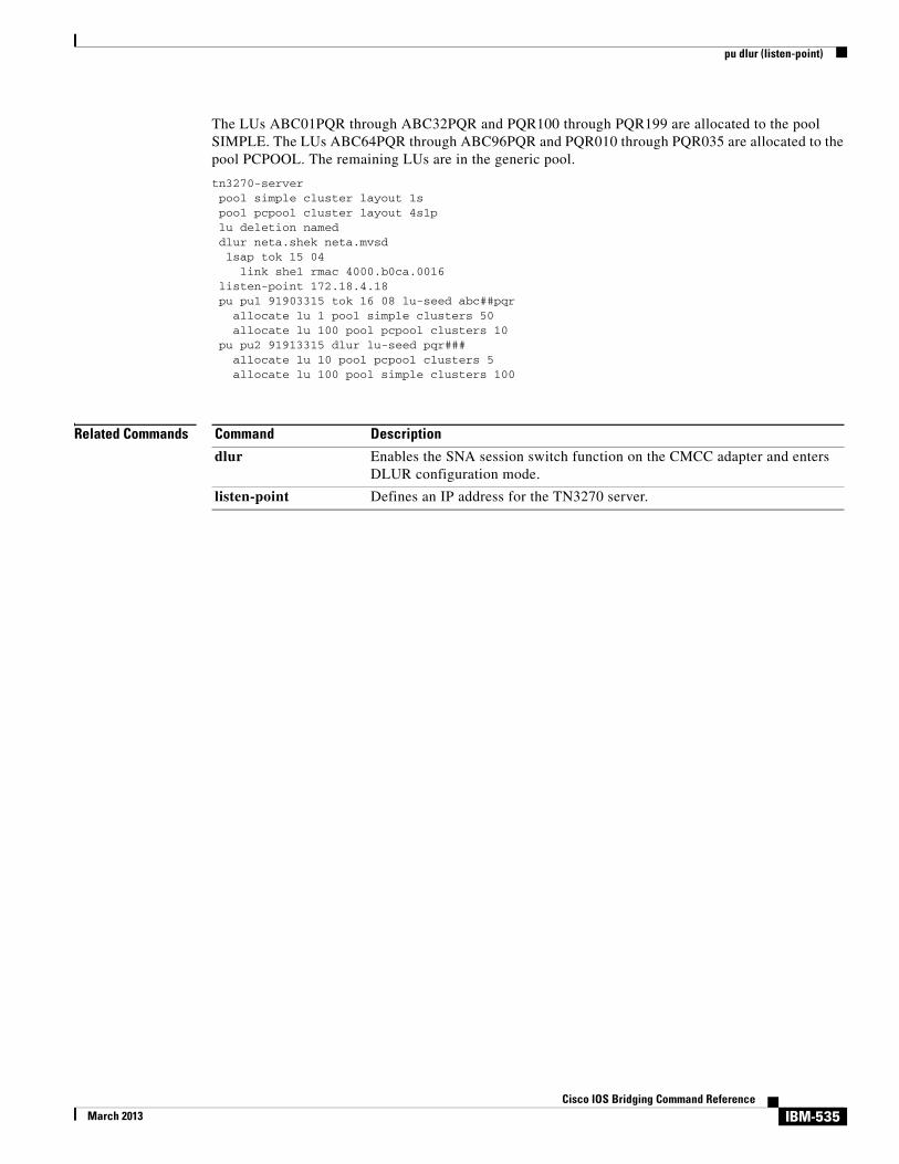
pu dlur (listen-point)
The LUs ABC01PQR through ABC32PQR and PQR100 through PQR199 are allocated to the pool SIMPLE. The LUs ABC64PQR through ABC96PQR and PQR010 through PQR035 are allocated to the pool PCPOOL. The remaining LUs are in the generic pool.
tn3270-server pool simple cluster layout 1s pool pcpool cluster layout 4s1p lu deletion named dlur neta.shek neta.mvsd
lsap tok 15 04 link she1 rmac 4000.b0ca.0016 listen-point 172.18.4.18 pu pu1 91903315 tok 16 08 lu-seed abc##pqr allocate lu 1 pool simple clusters 50 allocate lu 100 pool pcpool clusters 10 pu pu2 91913315 dlur lu-seed pqr### allocate lu 10 pool pcpool clusters 5 allocate lu 100 pool simple clusters 100
Related Commands Command Description
dlur Enables the SNA session switch function on the CMCC adapter and enters DLUR configuration mode.
listen-point Defines an IP address for the TN3270 server.
IBM-535Cisco IOS Bridging Command Reference
March 2013

qllc accept-all-calls
qllc accept-all-callsTo enable the router to accept a call from any remote X.25 device, use the qllc accept-all-calls command in interface configuration mode. To cancel the request, use the no form of this command.
qllc accept-all-calls
no qllc accept-all-calls
Syntax Description This command has no arguments or keywords.
Defaults Disabled
Command Modes Interface configuration
Command History
Usage Guidelines This command allows Qualified Logical Link Control (QLLC) to accept all inbound X.25 calls, provided that the QLLC Call User Data (CUD) is in the call packet and the destination X.121 address in the call packet matches the serial interface’s configured destination X.121 address or subaddress. When this command is used, the source X.121 address need not be configured via an x25 map qllc command for the call to be accepted.
This command is applicable to QLLC support for data-link switching plus (DLSw+), Advanced Peer-to-Peer Networking (APPN), and downstream physical unit (DSPU). It is not applicable to QLLC support for source-route bridging (SRB) and remote source-route bridging (RSRB).
Examples The following example enables QLLC connectivity for DLSw+ and allows QLLC to accept all inbound X.25 calls. Every X.25 connection request for X.121 address 0308 with QLLC CUD is directed to DLSw+. The first switched virtual circuit (SVC) to be established will be mapped to virtual MAC address 4000.0B0B.0001. If a call comes in with an X.121 address of 0308, the call will be forwarded to MAC address 4001.1161.1234.
interface serial 0encapsulation x25x25 address 0308qllc accept-all-callsqllc dlsw vmac 4000.0B0B.0001 500 partner 4001.1161.1234
Release Modification
11.2 F This command was introduced.
12.2(33)SRA This command was integrated into Cisco IOS Release 12.2(33)SRA.
12.2SX This command is supported in the Cisco IOS Release 12.2SX train. Support in a specific 12.2SX release of this train depends on your feature set, platform, and platform hardware.
IBM-536Cisco IOS Bridging Command Reference
March 2013

qllc accept-all-calls
Related Commands Command Description
x25 map qllc Specifies the X.121 address of the remote X.25 device with which communication is planned using QLLC conversion.
IBM-537Cisco IOS Bridging Command Reference
March 2013

qllc dlsw
qllc dlswTo enable data-link switching plus (DLSw+) over Qualified Logical Link Control (QLLC), use the qllc dlsw command in interface configuration mode. To cancel the configuration, use the no form of this command.
qllc dlsw {subaddress subaddress | pvc pvc-low [pvc-high]} [vmac vmacaddr poolsize] [partner partner-macaddr] [sap ssap dsap] [xid xidstring] [npsi-poll]
no qllc dlsw {subaddress subaddress | pvc pvc-low [pvc-high]} [vmac vmacaddr poolsize] [partner partner-macaddr] [sap ssap dsap] [xid xidstring] [npsi-poll]
Syntax Description
Defaults No default behavior or values
Command Modes Interface configuration
Command History
subaddress subaddress An X.121 subaddress.
pvc Map one or more permanent virtual circuits (PVCs) to a particular QLLC service (in this case DLSw+). QLLC will attempt to reach the partner by sending and ID.STN.IND to DLSw+.
pvc-low Lowest logical channel number (LCN) for a range of X.25 PVCs. Acceptable values for PVCs are decimal numbers from 1 to 4095.
pvc-high (Optional) Highest LCN. If not specified, the range of PVCs consists of just one PVC.
vmac vmacaddr (Optional) Defines either the only virtual MAC address used for DLSw+ or the lowest virtual MAC address in a pool of virtual MAC addresses.
poolsize (Optional) Specify the number of contiguous virtual MAC addresses that have been reserved for DLSw+. If the parameter is not present, then only one virtual MAC address is available.
partner partner-macaddr
(Optional) Virtual MAC address to which an incoming call wants to connect. The qllc dlsw command must be repeated for each different partner. Each partner is identified by a unique subaddress.
sap ssap dsap (Optional) Overrides the default service access point (SAP) values (04) for a Token Ring connection. dsap refers to the partner’s SAP address; ssap applies to the virtual MAC address that corresponds to the X.121 device.
xid xidstring (Optional) Exchange identification (XID) format 0 type 2 string.
npsi-poll (Optional) Inhibits forwarding a null XID on the X.25 link. Instead the Cisco IOS software will send a null XID response to the device that sent the null XID command.
Release Modification
11.0 This command was introduced.
IBM-538Cisco IOS Bridging Command Reference
March 2013

qllc dlsw
Usage Guidelines Any incoming call whose X.121 destination address matches the router’s X.121 address and this subaddress will be dispatched to DLSw+ (with an ID.STN IND). If a router is providing several QLLC services, different subaddresses must be used to discriminate between them. Subaddresses can be used even if a remote X.25 device is not explicitly mapped to a specific virtual MAC address. This is most useful when PU 2.1 devices are connecting to a host because the X.25 device’s control point name and network name are used to validate the connection, rather than some virtual MAC address. The subaddress is optional. If no subaddress is provided, any incoming call that matches the router’s X.121 address will be dispatched to DLSw+. On outgoing calls the subaddress is concatenated to the interface’s X.121 address.
When DLSw+ receives a Can You Reach inquiry about a virtual MAC address in the pool, the QLLC code will attempt to set up a virtual circuit to the X.121 address that maps to the virtual MAC address specified. If an incoming call is received, QLLC sends an ID.STN.IND with a virtual MAC address from the pool to DLSw+. If there is no virtual MAC address, then the x25 map qllc or x25 pvc qllc command must provide a virtual MAC address.
The npsi-poll keyword is needed to support PU 2.0 on the partner side that wants to connect to a front-end processor (FEP) on the X.25 side. In a Token Ring or DLSw+ environment, the PU 2.0 will send a null XID to the FEP. If the software forwards this null XID to an X.25 attached FEP, the FEP will assume that it is connecting to PU2.1, and will break off the connection when the PU 2.0 next sends an XID Format 0 Type 2.
Examples The following commands assign virtual MAC address 1000.0000.0001 to a remote X.25-attached 3174, which is then mapped to the X.121 address of the 3174 (31104150101) in an X.25-attached router:
interface serial 0x25 address 3110212011x25 map qllc 1000.000.0001 31104150101qllc dlsw partner 4000.1161.1234
12.2(33)SRA This command was integrated into Cisco IOS Release 12.2(33)SRA.
12.2SX This command is supported in the Cisco IOS Release 12.2SX train. Support in a specific 12.2SX release of this train depends on your feature set, platform, and platform hardware.
Release Modification
IBM-539Cisco IOS Bridging Command Reference
March 2013

qllc largest-packet
qllc largest-packetTo indicate the maximum size of the Systems Network Architecture (SNA) packet that can be sent or received on an X.25 interface configured for Qualified Logical Link Control (QLLC) conversion, use the qllc largest-packet command in interface configuration mode. To restore the default largest packet size, use the no form of this command.
qllc largest-packet virtual-mac-addr max-size
no qllc largest-packet virtual-mac-addr max-size
Syntax Description
Defaults Maximum size is 265 bytes.
Command Modes Interface configuration
Command History
Usage Guidelines SNA packets that are larger than the largest value allowed on the X.25 connection and are received on the Logical Link Control, type 2 (LLC2) interface are segmented before being sent on the X.25 interface. When a segmented packet is received on the X.25 interface, it is passed immediately to the LLC2 interface, and no effort is made to wait for the segment to be completed.
When the remote X.25 device has a limit on the maximum total length of recombined X.25 segments it will support, you can use the qllc largest-packet command to ensure that the length is not exceeded. For example, a device whose maximum SNA packet size is limited to 265 bytes might not be able to handle a series of X.25 packets that it has to recombine to make a 4, 8, or 17 KM SNA packet, such as one often encounters in an LLC2 environment.
You use the qllc largest-packet command in conjunction with the x25 map qllc and qllc srb commands.
virtual-mac-addr Virtual MAC address associated with the remote X.25 device, as defined using the x25 map qllc or x25 pvc qllc interface configuration command. This address is written as a dotted triple of four-digit hexadecimal numbers.
max-size Maximum size, in bytes, of the SNA packet that can be sent or received on the X.25 interface configured for QLLC conversion. This value must agree with the value configured in the remote SNA device. The valid range is from 0 to 1024.
Release Modification
10.3 This command was introduced.
12.2(33)SRA This command was integrated into Cisco IOS Release 12.2(33)SRA.
12.2SX This command is supported in the Cisco IOS Release 12.2SX train. Support in a specific 12.2SX release of this train depends on your feature set, platform, and platform hardware.
IBM-540Cisco IOS Bridging Command Reference
March 2013

qllc largest-packet
Note Do not configure the maximum SNA packet size on an X.25 interface to be larger than the maximum SNA packet size allowed on the LLC2 interface.
Consult your IBM documentation to set the maximum packet size on the remote X.25 device.
Examples In the following example, the maximum packet size that has been established for the virtual circuit is used as the maximum packet size that can be sent or received on the X.25 interface:
interface serial 0encapsulation x25x25 address 31102120100x25 map qllc 0100.0000.0001 31104150101qllc srb 0100.0000.0001 201 100
!qllc partner 0100.0000.0001 4000.0101.0132qllc xid 0100.0000.0001 01720001qllc largest-packet 0100.0000.0001 521
Related Commands Command Description
qllc srb Enables QLLC conversion on a serial interface configured for X.25 communication.
x25 map qllc Specifies the X.121 address of the remote X.25 device with which communication is planned using QLLC conversion.
x25 pvc qllc Associates a virtual MAC address with a PVC for communication using QLLC conversion.
IBM-541Cisco IOS Bridging Command Reference
March 2013

qllc npsi-poll
qllc npsi-pollTo enable a connection between a physical unit (PU) 2 on the LAN side and a front-end processor (FEP) running Network Control Program (NCP) Packet Switching Interface (NPSI) on the X.25 side, use the qllc npsi-poll command in interface configuration mode. To disable this capability, use the no form of this command.
qllc npsi-poll virtual-mac-addr
no qllc npsi-poll virtual-mac-addr
Syntax Description
Defaults Disabled
Command Modes Interface configuration
Command History
Usage Guidelines The qllc npsi-poll command is necessary only when the upstream device is a front-end processor (FEP) running NPSI and the downstream device is a PU 2.
This command is necessary because in a Token Ring or remote source-route bridging (RSRB) environment the LAN attached devices start up by sending a null exchange ID packet upstream. If the Cisco IOS software forwards this null exchange identification (XID) to an X.25-attached FEP, the FEP responds as if it were connecting to a PU2.1 device, and breaks the connection when the PU 2 next sends an XID Format 0 Type 2. The qllc npsi-poll command intercepts any null XID packet that the software receives on the LAN interface, and returns a null XID response to the downstream device. It continues to allow XID Format 3 and XID Format 0 packets through the X.25 device.
Examples The following example facilitates a connection between a FEP running NPSI and a downstream PU 2.0:
qllc npsi-poll 0100.0000.0001
virtual-mac-addr MAC address associated with the remote X.25 device, as defined using the x25 map qllc or x25 pvc qllc interface configuration command. This address is written as a dotted triple of four-digit hexadecimal numbers.
Release Modification
11.1 This command was introduced.
12.2(33)SRA This command was integrated into Cisco IOS Release 12.2(33)SRA.
12.2SX This command is supported in the Cisco IOS Release 12.2SX train. Support in a specific 12.2SX release of this train depends on your feature set, platform, and platform hardware.
IBM-542Cisco IOS Bridging Command Reference
March 2013
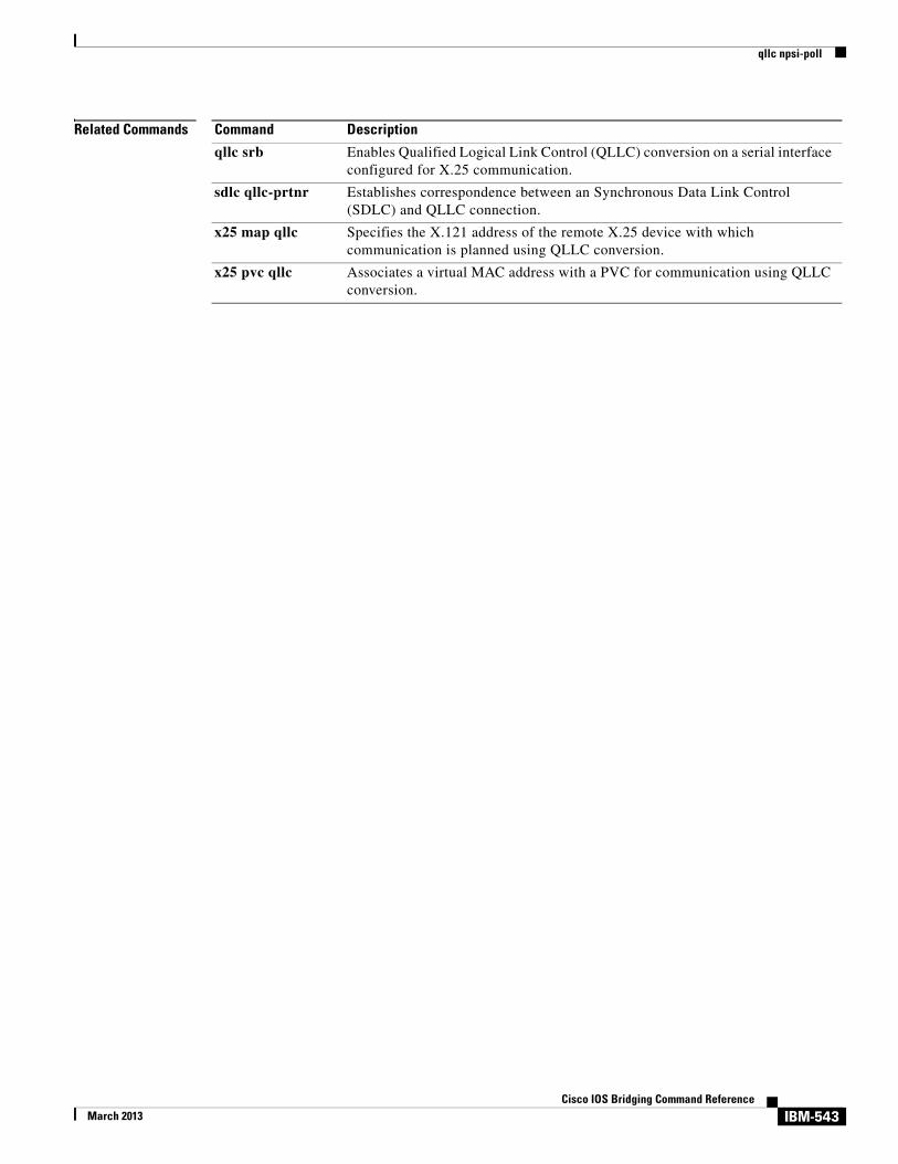
qllc npsi-poll
Related Commands Command Description
qllc srb Enables Qualified Logical Link Control (QLLC) conversion on a serial interface configured for X.25 communication.
sdlc qllc-prtnr Establishes correspondence between an Synchronous Data Link Control (SDLC) and QLLC connection.
x25 map qllc Specifies the X.121 address of the remote X.25 device with which communication is planned using QLLC conversion.
x25 pvc qllc Associates a virtual MAC address with a PVC for communication using QLLC conversion.
IBM-543Cisco IOS Bridging Command Reference
March 2013

qllc partner
qllc partnerTo enable a router configured for Qualified Logical Link Control (QLLC) conversion to open a connection to the local Token Ring device on behalf of the remote X.25 device when an incoming call is received, use the qllc partner command in interface configuration mode. To disable this capability, use the no form of this command.
qllc partner virtual-mac-addr mac-addr
no qllc partner virtual-mac-addr mac-addr
Syntax Description
Defaults Disabled
Command Modes Interface configuration
Command History
Usage Guidelines When the Cisco IOS software receives an incoming call from the designated X.121 address, it opens a Logical Link Control, type 2 (LLC2) connection with the device at the given MAC address. Both the MAC address of the Token Ring device and the virtual MAC address for the remote X.25 device with which it is to communicate are required in order for the software to initiate connections with the Token Ring device. This allows the Token Ring host to be permanently ready to accept a connection rather than requiring operator action at the host to initiate the connection with the X.25 device.
You must issue the qllc partner command for each remote X.25 device that will communicate with the local Token Ring host through this interface.
You use the qllc partner command in conjunction with the x25 map qllc and qllc srb commands.
virtual-mac-addr MAC address associated with the remote X.25 device, as defined using the x25 map qllc or x25 pvc qllc interface configuration command. This address is written as a dotted triple of four-digit hexadecimal numbers.
mac-addr 48-bit MAC address of the Token Ring host that will communicate with the remote X.25 device.
Release Modification
10.3 This command was introduced.
12.2(33)SRA This command was integrated into Cisco IOS Release 12.2(33)SRA.
12.2SX This command is supported in the Cisco IOS Release 12.2SX train. Support in a specific 12.2SX release of this train depends on your feature set, platform, and platform hardware.
IBM-544Cisco IOS Bridging Command Reference
March 2013

qllc partner
Examples In the following example, the qllc partner command is used to associate the virtual MAC address 0100.0000.0001, as defined in the previous x25 map qllc entry, with the MAC address of the Token Ring host that will communicate with the remote X.25 device:
interface serial 0encapsulation x25x25 address 31102120100x25 map qllc 0100.0000.0001 31104150101qllc srb 0100.0000.0001 201 100qllc partner 0100.0000.0001 4000.0101.0132qllc xid 0100.0000.0001 01720001
Related Commands Command Description
qllc srb Enables QLLC conversion on a serial interface configured for X.25 communication.
sdlc qllc-prtnr Establishes correspondence between an SDLC and QLLC connection.
x25 map qllc Specifies the X.121 address of the remote X.25 device with which communication is planned using QLLC conversion.
x25 pvc qllc Associates a virtual MAC address with a PVC for communication using QLLC conversion.
IBM-545Cisco IOS Bridging Command Reference
March 2013
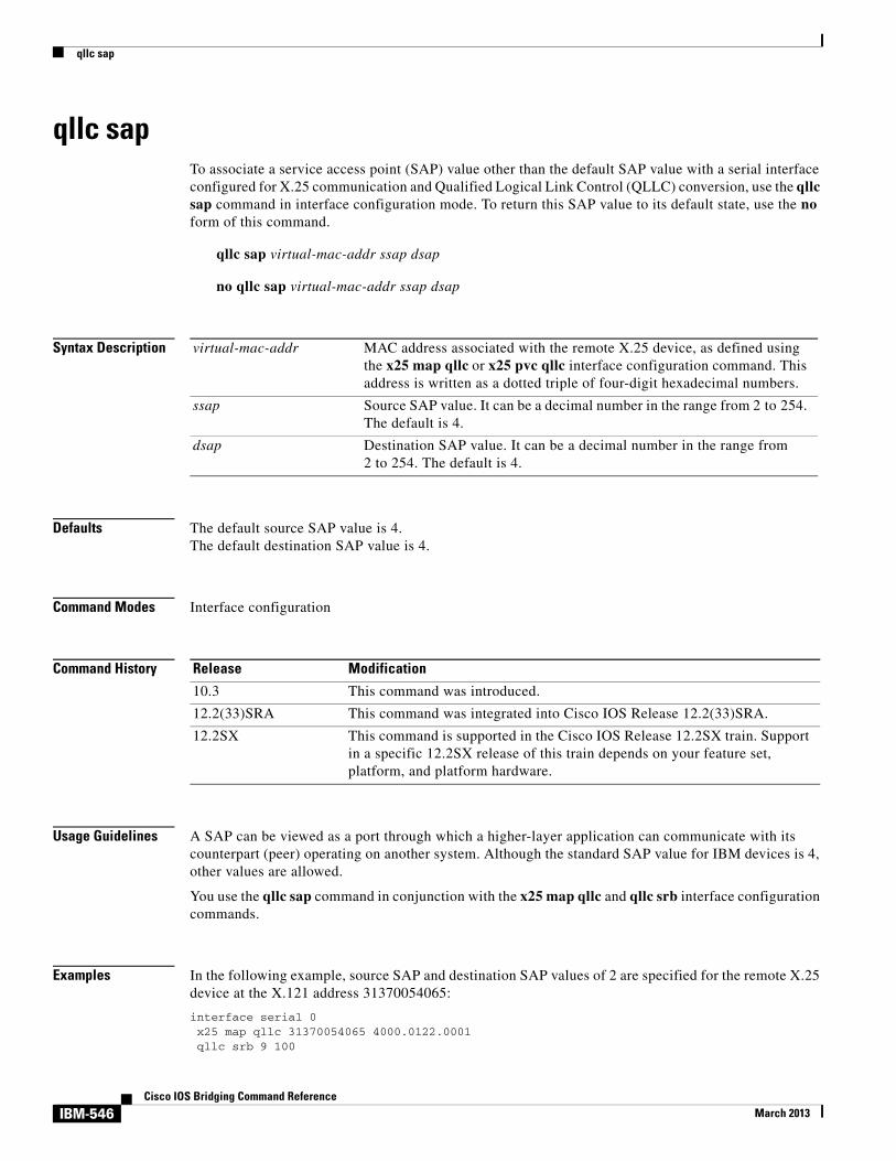
qllc sap
qllc sapTo associate a service access point (SAP) value other than the default SAP value with a serial interface configured for X.25 communication and Qualified Logical Link Control (QLLC) conversion, use the qllc sap command in interface configuration mode. To return this SAP value to its default state, use the no form of this command.
qllc sap virtual-mac-addr ssap dsap
no qllc sap virtual-mac-addr ssap dsap
Syntax Description
Defaults The default source SAP value is 4.The default destination SAP value is 4.
Command Modes Interface configuration
Command History
Usage Guidelines A SAP can be viewed as a port through which a higher-layer application can communicate with its counterpart (peer) operating on another system. Although the standard SAP value for IBM devices is 4, other values are allowed.
You use the qllc sap command in conjunction with the x25 map qllc and qllc srb interface configuration commands.
Examples In the following example, source SAP and destination SAP values of 2 are specified for the remote X.25 device at the X.121 address 31370054065:
interface serial 0x25 map qllc 31370054065 4000.0122.0001qllc srb 9 100
virtual-mac-addr MAC address associated with the remote X.25 device, as defined using the x25 map qllc or x25 pvc qllc interface configuration command. This address is written as a dotted triple of four-digit hexadecimal numbers.
ssap Source SAP value. It can be a decimal number in the range from 2 to 254. The default is 4.
dsap Destination SAP value. It can be a decimal number in the range from 2 to 254. The default is 4.
Release Modification
10.3 This command was introduced.
12.2(33)SRA This command was integrated into Cisco IOS Release 12.2(33)SRA.
12.2SX This command is supported in the Cisco IOS Release 12.2SX train. Support in a specific 12.2SX release of this train depends on your feature set, platform, and platform hardware.
IBM-546Cisco IOS Bridging Command Reference
March 2013

qllc sap
qllc sap 4000.0122.0001 02 02
Related Commands Command Description
qllc srb Enables QLLC conversion on a serial interface configured for X.25 communication.
x25 map qllc Specifies the X.121 address of the remote X.25 device with which communication is planned using QLLC conversion.
x25 pvc qllc Associates a virtual MAC address with a PVC for communication using QLLC conversion.
IBM-547Cisco IOS Bridging Command Reference
March 2013

qllc srb
qllc srbTo enable Qualified Logical Link Control (QLLC) conversion on a serial interface configured for X.25 communication, use the qllc srb command in interface configuration mode. To disable QLLC conversion on the interface, use the no form of this command.
qllc srb virtual-mac-addr srn trn
no qllc srb srn trn
Syntax Description
Defaults QLLC conversion is not enabled.
Command Modes Interface configuration
Command History
Usage Guidelines Any number of QLLC conversion connections using the same X.25 serial interface can share a source ring. However, this source ring must be a unique hexadecimal ring number within the source-bridged network.
If the router has only one Token Ring interface and is bridging from the remote X.25 devices to this interface, then the trn value is the number of the ring on that Token Ring interface. If the router has several Token Ring interfaces and interconnects them by means of the source-bridge sdllc-local-ack command, then the trn value is the number of that virtual ring group, as assigned using the source-bridge sdllc-local-ack
Use the qllc srb command to associate the ring number and bridge number that have been assigned to the interface with a virtual ring group of which the interface will be a part. The serial interface appears to be a ring, or source ring number, on a source-route bridge network, and ties in to the virtual ring group, or target ring number. The target ring number provides access to other real rings that have been
virtual-mac-addr MAC address associated with the remote X.25 device, as defined using the x25 map qllc or x25 pvc qllc interface configuration command. It must be 1 to 15 digits long.
srn Source ring number. This value defines a virtual ring for all of the remote X.25 devices attached to the QLLC interface.
trn Target ring number. It must be a virtual ring group that has been defined with the source-bridge sdllc-local-ack global configuration command.
Release Modification
10.3 This command was introduced.
12.2(33)SRA This command was integrated into Cisco IOS Release 12.2(33)SRA.
12.2SX This command is supported in the Cisco IOS Release 12.2SX train. Support in a specific 12.2SX release of this train depends on your feature set, platform, and platform hardware.
IBM-548Cisco IOS Bridging Command Reference
March 2013

qllc srb
designated using the source-bridge global configuration command. Note that you can configure QLLC conversion on a router containing no Token Ring interface cards, such as a router connecting a serial-attached device to an X.25 public data network (PDN).
The qllc srb command automatically turns on the Logical Link Control, type 2 (LLC2) process with default values. To change any of the LLC2 parameters (described in the “LLC2 and Synchronous Data Link Control (SDLC) Commands” chapter in the Cisco IOS Bridging and IBM Networking Configuration Guide.), apply their values to the serial interface that has been configured for QLLC conversion. This is done on the serial interface, even though LLC2 does not run on the serial interface, but on the virtual ring associated with the serial interface.
You use the qllc srb command in conjunction with the x25 map qllc command.
Examples In the following example, the qllc srb command is used to define a virtual ring number of 201 for the remote X.25 device, and an actual or virtual ring number of 100 for the Token Ring interface:
interface serial 0encapsulation x25x25 address 31102120100x25 map qllc 0100.0000.0001 31104150101qllc srb 0100.0000.0001 201 100
Related Commands Command Description
source-bridge Configures an interface for source-route bridging (SRB).
source-bridge sdllc-local-ack
Activates local acknowledgment for SDLLC sessions on a particular interface.
x25 map qllc Specifies the X.121 address of the remote X.25 device with which communication is planned using QLLC conversion.
x25 pvc qllc Associates a virtual MAC address with a PVC for communication using QLLC conversion.
IBM-549Cisco IOS Bridging Command Reference
March 2013

qllc xid
qllc xidTo associate an exchange ID (XID) value with the remote X.25 device that communicates through the Cisco IOS software using Qualified Logical Link Control (QLLC) conversion, use the qllc xid command in interface configuration mode. To disable XID processing for this address, use the no form of this command.
qllc xid virtual-mac-addr xid
no qllc xid virtual-mac-addr xid
Syntax Description
Defaults XID processing is not enabled.
Command Modes Interface configuration
Command History
Usage Guidelines Most QLLC installations do not need the qllc xid configuration command. It is needed only if the remote X.25 device is not configured to send its own XID. This is only possible for a device that is attached via a permanent virtual circuit (PVC). Even so, most devices that are connected via X.25 will send their own XIDs. Use the qllc xid command when the Token Ring host requires login validation for security purposes and the remote X.25 device does not send an XID. The XID value is used to reply to XID requests received on the Token Ring Logical Link Control, type 2 (LLC2) side of the connection. XID requests and responses are usually exchanged before sessions are started. The XID response to the XID request from the Token Ring host will contain the information you configure using the qllc xid command. The host will check the XID response it receives with the IDBLK and IDNUM parameters (configured in virtual telecommunications access method [VTAM]). If they match, the Token Ring host will initiate a session with the router. If they do not match, the host will not initiate a session with the router.
You use the qllc xid command in conjunction with the x25 map qllc and the qllc srb commands.
virtual-mac-addr MAC address associated with the remote X.25 device, as defined using the x25 map qllc or x25 pvc qllc interface configuration command. This address is written as a dotted triple of four-digit hexadecimal numbers.
xid Combined XID IDBLK and XID IDNUM you are associating with the X.25 device at this X.121 address. This hexadecimal value must be four bytes (eight digits) in length.
Release Modification
10.3 This command was introduced.
12.2(33)SRA This command was integrated into Cisco IOS Release 12.2(33)SRA.
12.2SX This command is supported in the Cisco IOS Release 12.2SX train. Support in a specific 12.2SX release of this train depends on your feature set, platform, and platform hardware.
IBM-550Cisco IOS Bridging Command Reference
March 2013
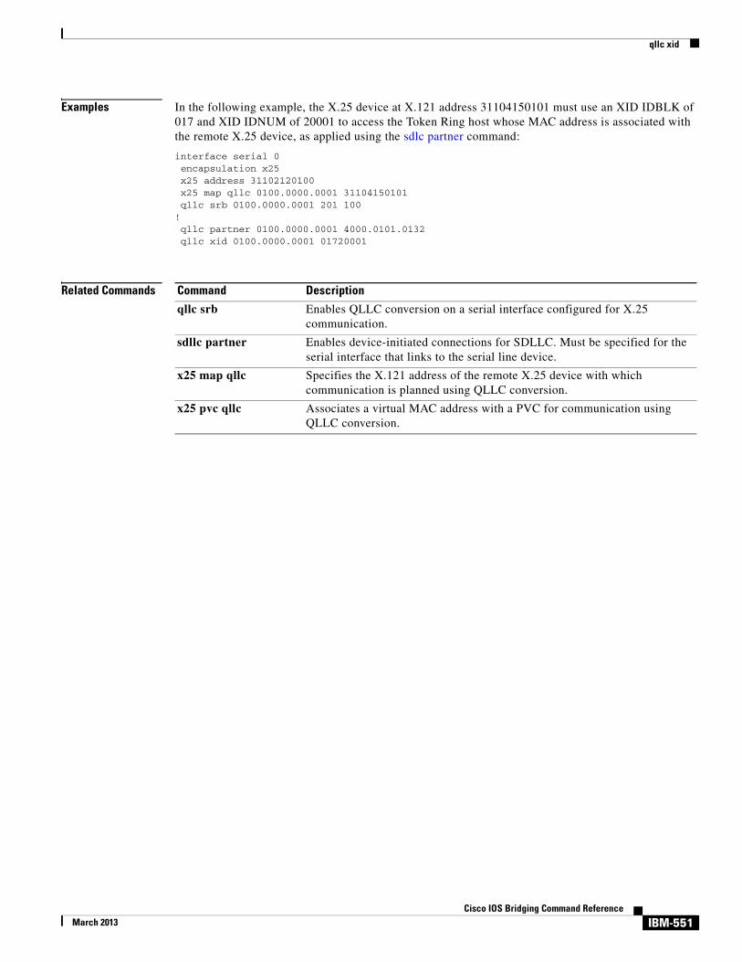
qllc xid
Examples In the following example, the X.25 device at X.121 address 31104150101 must use an XID IDBLK of 017 and XID IDNUM of 20001 to access the Token Ring host whose MAC address is associated with the remote X.25 device, as applied using the sdlc partner command:
interface serial 0encapsulation x25x25 address 31102120100x25 map qllc 0100.0000.0001 31104150101qllc srb 0100.0000.0001 201 100
!qllc partner 0100.0000.0001 4000.0101.0132qllc xid 0100.0000.0001 01720001
Related Commands Command Description
qllc srb Enables QLLC conversion on a serial interface configured for X.25 communication.
sdllc partner Enables device-initiated connections for SDLLC. Must be specified for the serial interface that links to the serial line device.
x25 map qllc Specifies the X.121 address of the remote X.25 device with which communication is planned using QLLC conversion.
x25 pvc qllc Associates a virtual MAC address with a PVC for communication using QLLC conversion.
IBM-551Cisco IOS Bridging Command Reference
March 2013
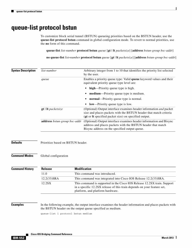
queue-list protocol bstun
queue-list protocol bstun To customize block serial tunnel (BSTUN) queueing priorities based on the BSTUN header, use the queue-list protocol bstun command in global configuration mode. To revert to normal priorities, use the no form of this command.
queue-list list-number protocol bstun queue [gt | lt packetsize] [address bstun-group bsc-addr]
no queue-list list-number protocol bstun queue [gt | lt packetsize] [address bstun-group bsc-addr]
Syntax Description
Defaults Prioritize based on BSTUN header.
Command Modes Global configuration
Command History
Examples In the following example, the output interface examines the header information and places packets with the BSTUN header on the output queue specified as medium.
queue-list 1 protocol bstun medium
list-number Arbitrary integer from 1 to 10 that identifies the priority list selected by the user.
queue Enables a priority queue type: Valid queue keyword values and their equivalent priority queue type level are:
• high—Priority queue type is high.
• medium—Priority queue type is medium.
• normal—Priority queue type is normal.
• low—Priority queue type is low.
gt | lt packetsize (Optional) Output interface examines header information and packet size and places packets with the BSTUN header that match criteria (gt or lt specified packet size) on specified output.
address bstun-group bsc-addr (Optional) Output interface examines header information and Bisync address and places packets with the BSTUN header that match Bisync address on the specified output queue.
Release Modification
11.0 This command was introduced.
12.2(33)SRA This command was integrated into Cisco IOS Release 12.2(33)SRA.
12.2SX This command is supported in the Cisco IOS Release 12.2SX train. Support in a specific 12.2SX release of this train depends on your feature set, platform, and platform hardware.
IBM-552Cisco IOS Bridging Command Reference
March 2013

queue-list protocol bstun
Related Commands Command Description
encapsulation bstun Configures BSTUN on a particular serial interface.
IBM-553Cisco IOS Bridging Command Reference
March 2013

queue-list protocol ip tcp
queue-list protocol ip tcpTo customize block serial tunnel (BSTUN) queueing priorities based on the TCP port, use the queue-list protocol ip tcp command in global configuration mode. To revert to normal priorities, use the no form of this command.
queue-list list-number protocol ip queue tcp tcp-port-number
no queue-list list-number protocol ip queue tcp tcp-port-number
Syntax Description
Defaults The default queue value is normal.
Command Modes Global configuration
Command History
list-number Arbitrary integer from 1 to 10 that identifies the priority list selected by the user.
queue Enables a priority queue type: Valid queue keyword values and their equivalent priority queue type level are:
• high—Priority queue type is high.
• medium—Priority queue type is medium.
• normal—Priority queue type is normal.
• low—Priority queue type is low.
The default queue value is normal.
tcp-port-number BSTUN port and priority settings are as follows:
• High—BSTUN port 1976
• Medium—BSTUN port 1977
• Normal—BSTUN port 1978
• Low—BSTUN port 1979
Serial tunnel (STUN) port and priority settings are as follows:
• High—STUN port 1994
• Medium—STUN port 1990
• Normal—STUN port 1991
• Low—STUN port 1992
Release Modification
11.0 This command was introduced.
IBM-554Cisco IOS Bridging Command Reference
March 2013

queue-list protocol ip tcp
Examples In the following example, queueing priority for address C1 using priority list 1 is set to high. A priority queue of high is assigned to BSTUN port 1976.
queue-list bstun high address 1 c1queue-list 1 protocol ip high 1976
Related Commands
12.2(33)SRA This command was integrated into Cisco IOS Release 12.2(33)SRA.
12.2SX This command is supported in the Cisco IOS Release 12.2SX train. Support in a specific 12.2SX release of this train depends on your feature set, platform, and platform hardware.
Release Modification
Command Description
encapsulation bstun Configures BSTUN on a particular serial interface.
IBM-555Cisco IOS Bridging Command Reference
March 2013

response-time group
response-time groupTo configure a client subnet group for response-time measurements, use the response-time group TN3270 server configuration command. To remove a client subnet group from response-time measurements, use the no form of this command.
response-time group name [bucket boundaries t1 t2 t3 t4] [multiplier m]
no response-time group name
Syntax Description
Defaults Bucket boundaries and the multiplier value are fixed to the following defaults:
• Bucket boundaries—10, 20, 50, 100
• Multiplier—30
Command Modes TN3270 server configuration
Command History
Usage Guidelines Multiple response-time groups can be configured within the scope of available memory. When this command is used, up to 1024 IP subnets can be defined per response-time group with the client ip command. All TN3270 clients belonging to subnets configured within a specific response-time group are added to the response-time group when they connect as clients.
name Alphanumeric string for the response-time group name. The maximum length of the name is 24 characters. Lower or uppercase letters can be used.
bucket boundaries t1 t2 t3 t4
(Optional) Unsigned 32-bit quantity that defines a bucket boundary in tenths of seconds. For other types of client groups, the bucket boundaries and multiplier values are fixed to the following defaults:
• Bucket boundaries—10, 20, 50, 100
• Multiplier—30
multiplier m (Optional) Number, in the range from 1 to 5760, which when multiplied by the sample interval of 20 seconds, determines the collection interval.
Release Modification
11.2(18)BC This command was introduced.
12.0(5)T This command was integrated into Cisco IOS Release 12.0 T.
12.2(33)SRA This command was integrated into Cisco IOS Release 12.2(33)SRA.
12.2SX This command is supported in the Cisco IOS Release 12.2SX train. Support in a specific 12.2SX release of this train depends on your feature set, platform, and platform hardware.
IBM-556Cisco IOS Bridging Command Reference
March 2013

response-time group
If the IP address and mask combination already exists within any response-time group, the following error message is displayed:
Subnet 10.1.1.0 255.255.255.248 already exists in client group MYSUBNET
Examples In the following example, the response-time group MYSUBNET is configured:
tn3270-serverresponse-time group MYSUBNET bucket boundaries 15 25 60 120 multiplier 35client ip 10.1.1.0 255.255.255.248client ip 10.1.2.0 255.255.255.248
Related Commands Command Description
client ip Adds an IP subnet to a client subnet response-time group.
show extended channel tn3270-server response-time application
Displays information about application response-time client groups.
show extended channel tn3270-server response-time global
Displays information about the global response-time client group.
show extended channel tn3270-server response-time link
Displays information about host link response-time client groups.
show extended channel tn3270-server response-time listen-point
Displays information about listen point response-time client groups.
show extended channel tn3270-server response-time subnet
Displays information about Subnet response-time client groups.
IBM-557Cisco IOS Bridging Command Reference
March 2013

rif
rifTo enter static source-route information into the Routing Information Field (RIF) cache, use the rif command in global configuration mode. If a Token Ring host does not support the use of IEEE 802.2 TEST or XID datagrams as explorer packets, you may need to add static information to the RIF cache of the router. To remove an entry from the cache, use the no form of this command.
rif mac-address rif-string {interface-name | ring-group ring}
no rif mac-address rif-string {interface-name | ring-group ring}
Syntax Description
Defaults No static source-route information is entered.
Command Modes Global configuration
Command History
Usage Guidelines You must specify either an interface name or a ring group number to indicate the origin of the RIF. You specify an interface name (for example, tokenring 0) with the interface-name argument, and you specify a ring group number with the ring-group ring keyword and argument. The ring group number must match the number you specified with the source-bridge ring-group command. Ring groups are explained in the “Configuring Source-Route Bridging” chapter of the Bridging and IBM Networking Configuration Guide.
Using the command rif mac-address without any other arguments puts an entry into the RIF cache indicating that packets for this MAC address should not have RIF information.
Do not configure a static RIF with any of the all rings type codes. Doing so causes traffic for the configured host to appear on more than one ring and leads to unnecessary congestion.
mac-address 12-digit hexadecimal string written as a dotted triple of four-digit hexadecimal numbers; for example, 0010.0a00.20a6.
rif-string Series of 4-digit hexadecimal numbers separated by a period (.). This RIF string is inserted into the packets sent to the specified MAC address.
interface-name Interface name (for example, tokenring 0) that indicates the origin of the RIF.
ring-group Specifies the origin of the RIF is a ring group.
ring Ring group number that indicates the origin of the RIF. This ring group number must match the number you have specified with the source-bridge ring-group command. The valid range is from 1 to 4095.
Release Modification
10.0 This command was introduced.
12.2(33)SRA This command was integrated into Cisco IOS Release 12.2(33)SRA.
12.2SX This command is supported in the Cisco IOS Release 12.2SX train. Support in a specific 12.2SX release of this train depends on your feature set, platform, and platform hardware.
IBM-558Cisco IOS Bridging Command Reference
March 2013

rif
Note Input to the source-bridge interface configuration command is in decimal format. RIF displays and input are in hexadecimal format, and IBM source-route bridges use hexadecimal for input. It is essential that bridge and ring numbers are consistent for proper network operation. This means you must explicitly declare the numbers to be hexadecimal by preceding the number with 0x, or you must convert IBM hexadecimal numbers to a decimal equivalent when entering them. For example, IBM hexadecimal bridge number 10 would be entered as hexadecimal number 0x10 or decimal number 16 in the configuration commands. In the displays, these commands always will be in decimal.
Examples The following example configuration sets up a static RIF:
! insert entry with MAC address 1000.5A12.3456 and RIF of ! 0630.0081.0090 into RIF cache rif 1000.5A12.3456 0630.0081.0090 tokenring 0
Related Commands Command Description
multiring Enables collection and use of RIF information.
source-bridge ring-group Defines or removes a ring group from the configuration.
IBM-559Cisco IOS Bridging Command Reference
March 2013

rif timeout
rif timeoutTo determine the number of minutes an inactive Routing Information Field (RIF) entry is kept, use the rif timeout command in global configuration mode. To restore the default, use the no form of this command.
rif timeout minutes
no rif timeout
Syntax Description
Defaults 15 minutes
Command Modes Global configuration
Command History
Usage Guidelines A RIF entry is cached based on the MAC address and the interface.
RIF information is maintained in a cache whose entries are aged. A RIF entry can be aged out even if there is active traffic, but the traffic is fast or autonomously switched. Until a RIF entry is removed from the cache, no new information is accepted for that RIF entry.
A RIF entry is refreshed only if a RIF field of an incoming frame is identical to the RIF information of the RIF entry in the cache.
Examples The following example changes the timeout period to 5 minutes:
rif timeout 5
Related Commands
minutes Number of minutes an inactive RIF entry is kept. The value must be greater than 0. Default is 15 minutes.
Release Modification
10.0 This command was introduced.
12.2(33)SRA This command was integrated into Cisco IOS Release 12.2(33)SRA.
12.2SX This command is supported in the Cisco IOS Release 12.2SX train. Support in a specific 12.2SX release of this train depends on your feature set, platform, and platform hardware.
Command Description
clear rif-cache Clears the entire RIF cache.
rif validate-enable Enables RIF validation for entries learned on an interface (Token Ring or FDDI).
show rif Displays the current contents of the RIF cache.
IBM-560Cisco IOS Bridging Command Reference
March 2013

rif validate-age
rif validate-ageTo define the validation time when the Cisco IOS software is acting as a proxy for NetBIOS NAME_QUERY packet or for explorer frames, use the rif validate-age command in global configuration mode.
rif validate-age seconds
no rif validate-age seconds
Syntax Description
Defaults 2 seconds
Command Modes Global configuration
Command History
Usage Guidelines If the timer expires before the response is received, the Routing Information Field (RIF) entry or the NetBIOS cache entry is marked as invalid and is flushed from the cache table when another explorer or NAME_QUERY packet is received.
Examples The following example specifies the interval at which a proxy is sent to be 3 seconds:
rif validate-age 3
Related Commands
seconds Interval, in seconds, at which a proxy is sent. The valid range is any number greater than 0. Default is 2 seconds.
Release Modification
10.0 This command was introduced.
12.2(33)SRA This command was integrated into Cisco IOS Release 12.2(33)SRA.
12.2SX This command is supported in the Cisco IOS Release 12.2SX train. Support in a specific 12.2SX release of this train depends on your feature set, platform, and platform hardware.
Command Description
rif Enters static source-route information into the RIF cache.
rif timeout Determines the number of minutes an inactive RIF entry is kept.
IBM-561Cisco IOS Bridging Command Reference
March 2013

rif validate-enable
rif validate-enableTo enable Routing Information Field (RIF) validation for entries learned on an interface (Token Ring or Fiber Distributed Data Interface [FDDI]), use the rif validate-enable command in global configuration mode. To disable the specification, use the no form of this command.
rif validate-enable
no rif validate-enable
Syntax Description This command has no arguments or keywords.
Defaults RIF validation is enabled.
Command Modes Global configuration
Command History
Usage Guidelines A RIF validation algorithm is used for the following cases:
• To decrease convergence time to a new source-route path when an intermediate bridge goes down.
• To keep a valid RIF entry in a RIF cache even if a RIF entry is not refreshed either because traffic is fast or autonomously switched, or because there is no traffic.
A directed IEEE TEST command is sent to the destination MAC address. If a response received in the time specified by the rif validate-age command, the entry is refreshed and is considered valid. Otherwise, the entry is removed from the cache. To prevent sending too many TEST commands, any entry that has been refreshed in fewer than 70 seconds is considered valid.
Validation is triggered as follows:
• When a RIF entry is found in the cache.
• When a RIF field of an incoming frame and the RIF information of the RIF entry is not identical. If, as the result of validation, the entry is removed from the cache, the RIF field of the next incoming frame with the same MAC address is cached.
• When the RIF entry is not refreshed for the time specified in the rif timeout command.
Note If the RIF entry has been in the RIF cache for 6 hours, and has not been refreshed for the time specified in the rif timeout command, the entry is removed unconditionally from the cache.
Release Modification
11.0 This command was introduced.
12.2(33)SRA This command was integrated into Cisco IOS Release 12.2(33)SRA.
12.2SX This command is supported in the Cisco IOS Release 12.2SX train. Support in a specific 12.2SX release of this train depends on your feature set, platform, and platform hardware.
IBM-562Cisco IOS Bridging Command Reference
March 2013

rif validate-enable
Note The rif validate-enable commands have no effect on remote entries learned over RSRB.
Examples The following example enables RIF validation:
rif validate-enable
Related Commands Command Description
rif timeout Determines the number of minutes an inactive RIF entry is kept.
rif validate-age Defines the validation time when the Cisco IOS software is acting as a proxy for NetBIOS NAME_QUERY packet or for explorer frames.
rif validate-enable-age Enables RIF validation for stations on a source-route bridge network that do not respond to an IEEE TEST command.
rif validate-enable-route-cache Enables synchronization of the RIF cache with the protocol route cache.
IBM-563Cisco IOS Bridging Command Reference
March 2013

rif validate-enable-age
rif validate-enable-ageTo enable Routing Information Field (RIF) validation for stations on a source-route bridge network that do not respond to an IEEE TEST command, use the rif validate-enable-age command in global configuration mode. To disable the specification, use the no form of this command.
rif validate-enable-age
no rif validate-enable-age
Syntax Description This command has no arguments or keywords.
Defaults RIF validation is enabled.
Command Modes Global configuration
Command History
Usage Guidelines You must first issue the rif validate-enable command.
When this command is enabled, a RIF entry is not removed from the cache even if it becomes invalid. If the entry is refreshed, it becomes valid again.
If a RIF field of an incoming frame and the RIF information of the invalid RIF entry are not identical, the old RIF information is replaced by the new information.
Note The rif validate-enable commands have no effect on remote entries learned over remote source-route bridging (RSRB).
Examples The following example enables RIF validation:
rif validate-enable-age
Related Commands
Release Modification
11.0 This command was introduced.
12.2(33)SRA This command was integrated into Cisco IOS Release 12.2(33)SRA.
12.2SX This command is supported in the Cisco IOS Release 12.2SX train. Support in a specific 12.2SX release of this train depends on your feature set, platform, and platform hardware.
Command Description
rif validate-enable Enables RIF validation for entries learned on an interface (Token Ring or FDDI).
IBM-564Cisco IOS Bridging Command Reference
March 2013

rif validate-enable-route-cache
rif validate-enable-route-cacheTo enable synchronization of the Routing Information Field (RIF) cache with the protocol route cache, use the rif validate-enable-route-cache command in global configuration mode. To disable the specification, use the no form of this command.
rif validate-enable-route-cache
no rif validate-enable-route-cache
Syntax Description This command has no arguments or keywords.
Defaults Disabled
Command Modes Global configuration
Command History
Usage Guidelines When a RIF entry is removed from the RIF cache, or the RIF information in the RIF entry is changed, the protocol route caches are synchronized with the RIF cache.
Note The rif validate-enable commands have no effect on remote entries learned over remote source-route bridging (RSRB).
Examples The following example synchronizes the RIF cache with the protocol route cache:
rif validate-enable-route-cache
Related Commands
Release Modification
11.0 This command was introduced.
12.2(33)SRA This command was integrated into Cisco IOS Release 12.2(33)SRA.
12.2SX This command is supported in the Cisco IOS Release 12.2SX train. Support in a specific 12.2SX release of this train depends on your feature set, platform, and platform hardware.
Command Description
rif validate-enable Enables RIF validation for entries learned on an interface (Token Ring or FDDI).
IBM-565Cisco IOS Bridging Command Reference
March 2013

rsrb remote-peer lsap-output-list
rsrb remote-peer lsap-output-listTo define service access point (SAP) filters by local SAP (LSAP) address on the remote source-route bridging WAN interface, use the rsrb remote-peer lsap-output-list command in global configuration mode. To remove a SAP filter on the remote source-route bridging (RSRB) WAN interface, use the no form of this command.
rsrb remote-peer ring-group {tcp ip-address | fst ip-address | interface name} lsap-output-list access-list-number
no rsrb remote-peer ring-group {tcp ip-address | fst ip-address | interface name} lsap-output-list access-list-number
Syntax Description
Defaults No filters are assigned.
Command Modes Global configuration
Command History
Examples The following example specifies SAP filters by LSAP address:
rsrb remote-peer 1000 tcp 10.108.2.30 lsap-output-list 201
Related Commands
ring-group Virtual ring number of the remote peer.
tcp TCP encapsulation.
ip-address IP address.
fst Fast Sequenced Transport (FST) encapsulation.
ip-address IP address.
interface Direct encapsulation.
name Interface name.
access-list-number Number of the access list.
Release Modification
10.0 This command was introduced.
12.2(33)SRA This command was integrated into Cisco IOS Release 12.2(33)SRA.
12.2SX This command is supported in the Cisco IOS Release 12.2SX train. Support in a specific 12.2SX release of this train depends on your feature set, platform, and platform hardware.
Command Description
priority-list protocol Establishes queueing priorities based on the protocol type.
IBM-566Cisco IOS Bridging Command Reference
March 2013

rsrb remote-peer lsap-output-list
sap-priority Defines a priority list on an interface.
sap-priority-list Defines a priority list.
Command Description
IBM-567Cisco IOS Bridging Command Reference
March 2013

rsrb remote-peer netbios-output-list
rsrb remote-peer netbios-output-listTo filter packets by NetBIOS station name on a remote source-route bridging WAN interface, use the rsrb remote-peer netbios-output-list command in global configuration mode. To remove a filter on an remote source-route bridging (RSRB) WAN interface, use the no form of this command.
rsrb remote-peer ring-group {tcp ip-address | fst ip-address | interface type} netbios-output-list host name
no rsrb remote-peer ring-group {tcp ip-address | fst ip-address | interface type} netbios-output-list host name
Syntax Description
Defaults No filter is assigned.
Command Modes Global configuration
Command History
Examples The following example filters packets by NetBIOS station name:
rsrb remote-peer 1000 tcp 10.108.2.30 netbios-output-list host engineering
Related Commands
ring-group Virtual ring number of the remote peer.
tcp TCP encapsulation.
fst Fast Sequenced Transport (FST) encapsulation.
ip-address IP address.
interface Direct encapsulation.
type Interface name.
name Name of a NetBIOS access filter previously defined with one or more netbios access-list host global configuration commands.
Release Modification
10.0 This command was introduced.
12.2(33)SRA This command was integrated into Cisco IOS Release 12.2(33)SRA.
12.2SX This command is supported in the Cisco IOS Release 12.2SX train. Support in a specific 12.2SX release of this train depends on your feature set, platform, and platform hardware.
Command Description
netbios access-list host Assigns the name of the access list to a station or set of stations on the network. The NetBIOS station access list contains the station name to match, along with a permit or deny condition.
priority-list protocol Establishes queueing priorities based on the protocol type.
IBM-568Cisco IOS Bridging Command Reference
March 2013

rsrb remote-peer netbios-output-list
sap-priority Defines a priority list on an interface.
sap-priority-list Defines a priority list.
Command Description
IBM-569Cisco IOS Bridging Command Reference
March 2013