Ma Opt is Witch 5100 Relay en 061011
32
Operating Instructions OPTISWITCH 5100 C, 5150 C with relay output
-
Upload
jose-mario-ferreyra-moran -
Category
Documents
-
view
216 -
download
0
Transcript of Ma Opt is Witch 5100 Relay en 061011

8/6/2019 Ma Opt is Witch 5100 Relay en 061011
http://slidepdf.com/reader/full/ma-opt-is-witch-5100-relay-en-061011 1/32
Operating InstructionsOPTISWITCH 5100 C, 5150 C
with relay output

8/6/2019 Ma Opt is Witch 5100 Relay en 061011
http://slidepdf.com/reader/full/ma-opt-is-witch-5100-relay-en-061011 2/32
Contents
1 About this document
1.1 Function . . . . . . . . . . . . . . . . . . . . . . . . . . . . . 4
1.2 Target group . . . . . . . . . . . . . . . . . . . . . . . . . . 41.3 Symbolism used . . . . . . . . . . . . . . . . . . . . . . . 4
2 For your safety
2.1 Authorised personnel . . . . . . . . . . . . . . . . . . . . 52.2 Appropriate use. . . . . . . . . . . . . . . . . . . . . . . . 52.3 Warning about misuse . . . . . . . . . . . . . . . . . . . 52.4 CE conformity . . . . . . . . . . . . . . . . . . . . . . . . . 52.5 SIL conformity . . . . . . . . . . . . . . . . . . . . . . . . . 6
2.6 Safety instructions for Ex areas . . . . . . . . . . . . 63 Product description
3.1 Configuration. . . . . . . . . . . . . . . . . . . . . . . . . . 73.2 Principle of operation . . . . . . . . . . . . . . . . . . . . 73.3 Operation . . . . . . . . . . . . . . . . . . . . . . . . . . . . 83.4 Storage and transport . . . . . . . . . . . . . . . . . . . 9
4 Mounting
4.1 General instructions. . . . . . . . . . . . . . . . . . . . . 10
4.2 Mounting instructions . . . . . . . . . . . . . . . . . . . . 13
5 Connecting to voltage supply
5.1 Preparing the connection . . . . . . . . . . . . . . . . . 155.2 Connection steps. . . . . . . . . . . . . . . . . . . . . . . 15
5.3 Wiring plan, single chamber housing. . . . . . . . . 16
6 Set up
6.1 General. . . . . . . . . . . . . . . . . . . . . . . . . . . . . . 186.2 Adjustment elements . . . . . . . . . . . . . . . . . . . . 186.3 Function chart . . . . . . . . . . . . . . . . . . . . . . . . . 19
7 Maintenance and fault rectification
7.1 Maintenance . . . . . . . . . . . . . . . . . . . . . . . . . . 217.2 Rectify faults . . . . . . . . . . . . . . . . . . . . . . . . . . 217.3 Instrument repair . . . . . . . . . . . . . . . . . . . . . . . 22
8 Dismounting
8.1 Dismounting procedure . . . . . . . . . . . . . . . . . . 23
8.2 Disposal . . . . . . . . . . . . . . . . . . . . . . . . . . . . . 23
2 OPTISWITCH 5100 C, 5150 C - with relay output
Contents
3 0 4
2 6 -
E N- 0 6 0 8 3 1

8/6/2019 Ma Opt is Witch 5100 Relay en 061011
http://slidepdf.com/reader/full/ma-opt-is-witch-5100-relay-en-061011 3/32
9 Supplement
9.1 Technical data. . . . . . . . . . . . . . . . . . . . . . . . . 249.2 Dimensions . . . . . . . . . . . . . . . . . . . . . . . . . . . 29
OPTISWITCH 5100 C, 5150 C - with relay output 3
Contents
3 0 4 2 6 - E N - 0 6 0
8 3 1

8/6/2019 Ma Opt is Witch 5100 Relay en 061011
http://slidepdf.com/reader/full/ma-opt-is-witch-5100-relay-en-061011 4/32
1 About this document
1.1 Function
This operating instructions manual has all the information youneed for quick setup and safe operation. Please read this
manual before you start setup.
1.2 Target group
This operating instructions manual is directed to trained,
qualified personnel. The contents of this manual should be
made available to these personnel and put into practice by
them.
1.3 Symbolism used
Information, tip, note
This symbol indicates helpful additional information.
Caution: If this warning is ignored, faults or
malfunctions can result.
Warning: If this warning is ignored, injury to persons and / or
serious damage to the instrument can result.
Danger: If this warning is ignored, serious injury to personsand / or destruction of the instrument can result.
Ex applications
This symbol indicates special instructions for Ex applications.
l List
The dot set in front indicates a list with no implied sequence .
à Action
This arrow indicates a single action.
1 Sequence
Numbers set in front indicate successive steps in a procedure.
4 OPTISWITCH 5100 C, 5150 C - with relay output
About this document
3 0 4
2 6 -
E N- 0 6 0 8 3 1

8/6/2019 Ma Opt is Witch 5100 Relay en 061011
http://slidepdf.com/reader/full/ma-opt-is-witch-5100-relay-en-061011 5/32

8/6/2019 Ma Opt is Witch 5100 Relay en 061011
http://slidepdf.com/reader/full/ma-opt-is-witch-5100-relay-en-061011 6/32
2.6 SIL conformity
OPTISWITCH 5100 C, 5150 C fulfills the requirements of
functional safety according to IEC 61508 / IEC 61511. You can
find further information in the supplementary instructionsmanual "Safety M anual - F unctional safety ( SIL ) OPTISWITCH
5 XXX ".
2.7 Safety instructions for Ex areas
Please note the Ex-specific safety information for installation
and operation in Ex areas. These safety instructions are part of
the operating instructions manual and come with the Ex-
approved instruments.
6 OPTISWITCH 5100 C, 5150 C - with relay output
For your safety
3 0 4
2 6 -
E N- 0 6 0 8 3 1

8/6/2019 Ma Opt is Witch 5100 Relay en 061011
http://slidepdf.com/reader/full/ma-opt-is-witch-5100-relay-en-061011 7/32
3 Product description
3.1 Configuration
The scope of delivery encompasses:
l OPTISWITCH 5100 C, 5150 C level sensor
l Documentation
- this operating instructions manual
- Ex specific safety instructions (with Ex versions), if
necessary further certificates
OPTISWITCH 5100 C, 5150 C consists of the following
components:
l Housing cover
l Housing with electronics
l process fitting with tuning fork
1
2
3
F ig. 1: OPTISWITCH 5100 C, 5150 C with plastic housing
1 H ousing cover
2 H ousing with electronics
3 P rocess fi tting
3.2 Principle of operation
OPTISWITCH 5100 C, 5150 C is a level sensor with tuning
fork for level detection.
It is designed for industrial use in all areas of process
technology and can be used in liquids.
Typical applications are overfill and dry run protection. With a
tuning fork of only 40 mm length, OPTISWITCH 5100 C, 5150C can be also mounted, e.g. in pipelines from DN 25. The
small tuning fork allows use in vessels, tanks and pipes.
Scope of delivery
Components
Area of application
OPTISWITCH 5100 C, 5150 C - with relay output 7
Product description
3 0 4 2 6 - E N - 0 6 0
8 3 1

8/6/2019 Ma Opt is Witch 5100 Relay en 061011
http://slidepdf.com/reader/full/ma-opt-is-witch-5100-relay-en-061011 8/32
Thanks to its simple and robust measuring system, OPTI-
SWITCH 5100 C, 5150 C is virtually unaffected by the
chemical and physical properties of the liquid.
It functions even under difficult conditions such as turbulence,air bubbles, foam generation, buildup, strong external vibration
or changing products.
Fault monitoring
The electronics module of OPTISWITCH 5100 C, 5150 C
continuously monitors via frequency evaluation the following
criteria:
l Strong corrosion or damage on the tuning fork
l loss of vibration
l Line break to the piezo driveIf a malfunction is detected or in case of power failure, the
electronics takes on a defined switching condition, i.e. the
relay deenergises (safe condition).
The tuning fork is piezoelectrically energised and vibrates at its
mechanical resonance frequency of approx. 1200 Hz. The
piezos are fixed mechanically and are hence not subject to
temperature shock limitations. The frequency changes when
the tuning fork is covered by the medium. This change is
detected by the integrated oscillator and converted into a
switching command.
OPTISWITCH 5100 C, 5150 C is a compact instrument, i.e. it
can be operated without external evaluation system. The
integrated electronics evaluates the level signal and outputs a
switching signal. With this switching signal, a connected
device can be directly activated (e.g. a warning system, a PLC,
a pump etc.).
The exact range of the power supply is stated in the "T echnical data" in the "Supplement ".
3.3 Operation
The switching condition of OPTISWITCH 5100 C, 5150 C with
plastic housing can be checked when the housing is closed
(signal lamp). With the basic setting, products with a density
>0.7 g / cm³ (>0.025 lbs / in³) can be detected. The instrument
can be adapted if products with lower density should be
measured.
Physical principle
Power supply
8 OPTISWITCH 5100 C, 5150 C - with relay output
Product description
3 0 4
2 6 -
E N- 0 6 0 8 3 1

8/6/2019 Ma Opt is Witch 5100 Relay en 061011
http://slidepdf.com/reader/full/ma-opt-is-witch-5100-relay-en-061011 9/32
On the electronics module you will find the following indicating
and adjustment elements:
l signal lamp for indication of the switching condition (green /
red)l DIL switch for sensitivity adjustment
l Mode switch for selection of the switching condition (A / B)
3.4 Storage and transport
Your instrument was protected by packaging during transport.
Its capacity to handle normal loads during transport is assured
by a test according to DIN 55439.
The packaging of standard instruments consists of environ-
ment-friendly, recyclable cardboard. In addition, the sensor is
provided with a protective cover of ABS. For special versions
PE foam or PE foil is also used. Dispose of the packaging
material via specialised recycling companies.
l Storage and transport temperature see "Supplement -
T echnical data - Ambient conditions"
l Relative humidity 20 … 85 %
Packaging
Storage and transport tem-
perature
OPTISWITCH 5100 C, 5150 C - with relay output 9
Product description
3 0 4 2 6 - E N - 0 6 0
8 3 1

8/6/2019 Ma Opt is Witch 5100 Relay en 061011
http://slidepdf.com/reader/full/ma-opt-is-witch-5100-relay-en-061011 10/32
4 Mounting
4.1 General instructions
In general, OPTISWITCH 5100 C, 5150 C can be mounted inany position. The instrument must be mounted in such a way
that the tuning fork is at the height of the requested switching
point.
The tuning fork has lateral markings (notches), marking the
switching point with vertical mounting. The switching point
refers to water with the basic setting of the sensitivity switch
>=0.7 g / cm³ (>=0.025 lbs / in³). When mounting OPTISWITCH
5100 C, 5150 C, make sure that this marking is at the height of
the requested switching point. Keep in mind that the switchingpoint of the instrument is shifted if the medium has a density
other than water - water =1 g / cm³ (=0.036 lbs / in³). For
products <0.7 g / cm³ (<0.025 lbs / in³) and >0.5 g / cm³
(>0.018 lbs / in³) the density switch must be set to >=0.5 g / cm³.
2
3
14
F ig. 2 : V ertical mounting
1 Switching point approx . 13 mm ( approx . 0.51 in ) 2 Switching point with lower density
3 Switching point with higher density
4 Switching point approx . 27 mm ( approx . 1.06 in )
Switching point
10 OPTISWITCH 5100 C, 5150 C - with relay output
Mounting
3 0 4
2 6 -
E N- 0 6 0 8 3 1

8/6/2019 Ma Opt is Witch 5100 Relay en 061011
http://slidepdf.com/reader/full/ma-opt-is-witch-5100-relay-en-061011 11/32
1
F ig. 3: H orizontal mounting
1 Switching point
1
2
F ig. 4: H orizontal mounting ( recommended installation location - particularly for
adhesive products )
1 Switching point
2 M arking with screwed version on top - with fl ange versions directed to thefl ange holes
With flange versions, the fork is directed to the flange holes in
the following way.
F ig. 5 : F ork position with fl ange versions
Use the recommended cables (see chapter "Connecting to
power supply ") and tighten the cable gland.
You can give your OPTISWITCH 5100 C, 5150 C additional
protection against moisture penetration by leading the con-nection cable downward in front of the cable entry. Rain and
Moisture
OPTISWITCH 5100 C, 5150 C - with relay output 11
Mounting
3 0 4 2 6 - E N - 0 6 0
8 3 1

8/6/2019 Ma Opt is Witch 5100 Relay en 061011
http://slidepdf.com/reader/full/ma-opt-is-witch-5100-relay-en-061011 12/32

8/6/2019 Ma Opt is Witch 5100 Relay en 061011
http://slidepdf.com/reader/full/ma-opt-is-witch-5100-relay-en-061011 13/32
4.2 Mounting instructions
OPTISWITCH 5100 C, 5150 C has a defined thread starting
point. This means that every OPTISWITCH 5100 C, 5150 C is
in the same fork position after being screwed in. Removetherefore the supplied seal from the thread of OPTISWITCH
5100 C, 5150 C. This seal is not required when using a welded
socket with O-ring in front.
Keep in mind that this welded socket is not suitable for coated
instrument versions.
Screw OPTISWITCH 5100 C, 5150 C completely into the
welded socket. The later position can be determined already
before welding. Mark the appropriate position of the welded
socket. Before welding, unscrew OPTISWITCH 5100 C, 5150
C and remove the rubber ring from the welded socket. The
welded socket has a marking (notch). Weld the socket with the
notch facing upward, or in case of pipelines, aligned with the
direction of flow.
1
F ig. 7 : M arking on the welded socket 1 M arking
In case of horizontal mounting in adhesive and viscousproducts, the surfaces of the tuning fork should be vertical in
order to reduce buildup on the tuning fork. On the screwed
version you will find a marking on the hexagon. With this, you
can check the position of the tuning fork when screwing it in.
When the hexagon touches the seal, the thread can still be
turned by approx. half a turn. This is sufficient to reach the
recommended installation position.
With flange versions, the fork is directed to the flange holes.
Welded socket
Adhesive products
OPTISWITCH 5100 C, 5150 C - with relay output 13
Mounting
3 0 4 2 6 - E N - 0 6 0
8 3 1

8/6/2019 Ma Opt is Witch 5100 Relay en 061011
http://slidepdf.com/reader/full/ma-opt-is-witch-5100-relay-en-061011 14/32
When used in adhesive and viscous products, the tuning fork
should protrude into the vessel to avoid buildup. For that
reason, sockets for flanges and mounting bosses should be
avoided when mounting horizontally.
If OPTISWITCH 5100 C, 5150 C is mounted in the filling
stream, unwanted switching signals may be generated. MountOPTISWITCH 5100 C, 5150 C at a location in the vessel
where no disturbing influence from e.g. filling openings,
agitators etc. can occur.
To minimise flow resistance caused by the tuning fork,
OPTISWITCH 5100 C, 5150 C should be mounted in such a
way that the surfaces of the blades are parallel to the product
movement.
Instruments with enamel coating should be treated very
carefully and shocks should be avoided. Unpack OPTI-
SWITCH 5100 C, 5150 C directly before installation. InsertOPTISWITCH 5100 C, 5150 C carefully into the vessel
opening and avoid touching any sharp vessel parts.
Inflowing medium
Flows
Enamel coating
14 OPTISWITCH 5100 C, 5150 C - with relay output
Mounting
3 0 4
2 6 -
E N- 0 6 0 8 3 1

8/6/2019 Ma Opt is Witch 5100 Relay en 061011
http://slidepdf.com/reader/full/ma-opt-is-witch-5100-relay-en-061011 15/32
5 Connecting to voltage supply
5.1 Preparing the connection
Generally not the following safety instructions:
l Connect only in the complete absence of line voltage
In hazardous areas you should take note of the appropriate
regulations, conformity and type approval certificates of the
sensors and power supply units.
Connect the power supply according to the following diagrams.
Oscillator SWE60R is designed in protection class 1. To
maintain this protection class, it is absolutely necessary thatthe ground conductor be connected to the internal ground
terminal. Take note of the general installation regulations. As a
rule, connect OPTISWITCH 5100 C, 5150 C to vessel ground
(PA), or in case of plastic vessels, to the next ground potential.
On the side of the housing there is a ground terminal between
the cable entries. This connection serves to drain off electro-
static charges. In Ex applications, the installation regulations
for hazardous areas must be given priority.
The data for power supply are stated in the "T echnical data" in
the "Supplement ".
OPTISWITCH 5100 C, 5150 C is connected with standard
cable with round cross-section. An outer cable diameter of
5 … 9 mm (0.2 … 0.35 in) ensures the seal effect of the cable
entry.
If cable with a different diameter or wire cross section is used,
exchange the seal or use an appropriate cable connection.
In hazardous areas, only use approved cable connections forOPTISWITCH 5100 C, 5150 C.
Take note of the corresponding installation regulations for Ex
applications.
5.2 Connection steps
With Ex instruments, the housing cover may only be opened if
there is no explosive atmosphere present.
Proceed as follows:
Note safety instructions
Take note of safety
instructions for Ex
applications
Select power supply
Selecting the connection ca-
ble
Select connection
cable for Ex applica-
tions
OPTISWITCH 5100 C, 5150 C - with relay output 15
Connecting to voltage supply
3 0 4 2 6 - E N - 0 6 0
8 3 1

8/6/2019 Ma Opt is Witch 5100 Relay en 061011
http://slidepdf.com/reader/full/ma-opt-is-witch-5100-relay-en-061011 16/32
1 Unscrew the housing cover
2 Loosen compression nut of the cable entry
3 Remove approx. 10 cm (4 in) of the cable mantle, strip
approx. 1 cm (0.4 in) insulation from the ends of the
individual wires
4 Insert the cable into the sensor through the cable entry
5 Open the terminals with a screwdriver
6 Insert the wire ends into the open terminals according to
the wiring plan
7 Tighten the terminals with a screwdriver
8 Check the hold of the wires in the terminals by lightly
pulling on them
9 Tighten the compression nut of the cable entry, the seal
ring must completely encircle the cable
10 Screw the housing cover back on
The electrical connection is hence finished.
5.3 Wiring plan, single chamber housing
The following illustrations apply to the non-Ex as well as to the
EEx d version.
1
444
2 3
F ig. 8: M aterial versions, single chamber housing1 P lastic ( not with EE x d )
2 Aluminium3 Stainless steel ( not with EE x d )
4 F ilter element for pressure compensation ( not with EE x d )
Housing overview
16 OPTISWITCH 5100 C, 5150 C - with relay output
Connecting to voltage supply
3 0 4
2 6 -
E N- 0 6 0 8 3 1

8/6/2019 Ma Opt is Witch 5100 Relay en 061011
http://slidepdf.com/reader/full/ma-opt-is-witch-5100-relay-en-061011 17/32
3
5
1
2
4
SW E60R
20 -253V AC20 -72V DC
A
BL N
1 2 3 4 5 6 7 8
0,5 g / cm3
0,7 g / cm3
3 4 5 6 7 8
+
F ig. 9: E lectronics and connection compartment , single chamber housing
1 Control lamp 2 DIL switch for mode adjustment
3 DIL switch for switching point adaptation
4 Ground terminal 5 Screwed terminals
We recommend connecting OPTISWITCH 5100 C, 5150 C in
such a way that the switching circuit is open when there is a
level signal, line break or failure (safe condition).
The relays are always shown in non-operative condition.
1
2
3
1 2 3 4 5 6
+
L1
-
N
7 8
F ig. 10: W iring plan, single chamber housing1 Relay output
2 Relay output 3 V oltage supply
Electronics and connection
compartment
Wiring plan
OPTISWITCH 5100 C, 5150 C - with relay output 17
Connecting to voltage supply
3 0 4 2 6 - E N - 0 6 0
8 3 1

8/6/2019 Ma Opt is Witch 5100 Relay en 061011
http://slidepdf.com/reader/full/ma-opt-is-witch-5100-relay-en-061011 18/32
6 Set up
6.1 General
The numbers in brackets refer to the following illustrations.
The switching condition of the electronics can be checked on
the plastic housing with closed housing cover (control lamp). In
the basic setting, products with a density >0.7 g / cm³
(>0.025 lbs / in³) can be detected. For products with lower
density, the switch must be set to >0.5 g / cm³ (>0.018 lbs / in³).
On the electronics module you will find the following indicating
and adjustment elements:
l Signal lamp (1)
l DIL switch for mode adjustment - A / B (2)
l DIL switch for sensitivity adjustment (3)
Note:
For test purposes, immerse the tuning fork of OPTISWITCH
5100 C, 5150 C always in liquids. Do not test the function ofOPTISWITCH 5100 C, 5150 C with the hand. This can
damage the sensor.
6.2 Adjustment elements
1 2
3 4 5
6 7
8
1
2
3
F ig. 11: Oscillator SWE 60R - Relay output
1 Signal lamp ( LED )
2 DIL switch for mode adjustment 3 DIL switch for sensitivity adjustment
Function / Configuration
18 OPTISWITCH 5100 C, 5150 C - with relay output
Set up
3 0 4
2 6 -
E N- 0 6 0 8 3 1

8/6/2019 Ma Opt is Witch 5100 Relay en 061011
http://slidepdf.com/reader/full/ma-opt-is-witch-5100-relay-en-061011 19/32

8/6/2019 Ma Opt is Witch 5100 Relay en 061011
http://slidepdf.com/reader/full/ma-opt-is-witch-5100-relay-en-061011 20/32
Level Switching status Control lamp
Failure of the sup-
ply voltage
(mode A / B)
any
53 4(8)(6) (7)
Relay deenergized
Failure any
53 4(8)(6) (7)
Relay deenergized flashes red
20 OPTISWITCH 5100 C, 5150 C - with relay output
Set up
3 0 4
2 6 -
E N- 0 6 0 8 3 1

8/6/2019 Ma Opt is Witch 5100 Relay en 061011
http://slidepdf.com/reader/full/ma-opt-is-witch-5100-relay-en-061011 21/32

8/6/2019 Ma Opt is Witch 5100 Relay en 061011
http://slidepdf.com/reader/full/ma-opt-is-witch-5100-relay-en-061011 22/32

8/6/2019 Ma Opt is Witch 5100 Relay en 061011
http://slidepdf.com/reader/full/ma-opt-is-witch-5100-relay-en-061011 23/32
8 Dismounting
8.1 Dismounting procedure
Warning:Before dismounting, be aware of dangerous process con-
ditions such as e.g. pressure in the vessel, high temperatures,
corrosive or toxic products etc.
Take note of chapters "M ounting" and "Connecting to power
supply " and carry out the listed steps in reverse order.
With Ex instruments, the housing cover may only be opened if
there is no explosive atmosphere present.
8.2 Disposal
The instrument consists of materials which can be recycled by
specialised recycling companies. We use recyclable materials
and have designed the electronic modules to be easily
separable.
WEEE directive 2002 / 96 / EG
This instrument is not subject to the WEEE directive 2002 / 96 / EG and the respective national laws (in Germany, e.g.
ElektroG). Pass the instrument directly on to a specialised
recycling company and do not use the municipal collecting
points. These may be used only for privately used products
according to the WEEE directive.
Correct disposal avoids negative effects to persons and
environment and ensures recycling of useful raw materials.
Materials: see "T echnical data"
If you cannot dispose of the instrument properly, please
contact us about disposal methods or return.
OPTISWITCH 5100 C, 5150 C - with relay output 23
Dismounting
3 0 4 2 6 - E N - 0 6 0
8 3 1

8/6/2019 Ma Opt is Witch 5100 Relay en 061011
http://slidepdf.com/reader/full/ma-opt-is-witch-5100-relay-en-061011 24/32
9 Supplement
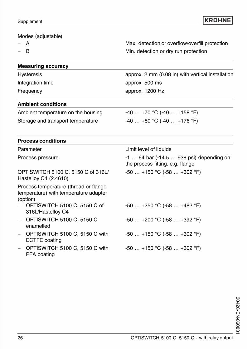
9.1 Technical data
General dataMaterial 316L corresponds to 1.4404 or 1.4435
Materials, wetted parts
- Process fitting - thread 316L, Hastelloy C4 (2.4602)
- Process fitting - flange 316L, 316L with Hastelloy C4 plated, enam-
elled steel, 316L with ECTFE coated, 316L with
PFA coated
- Process seal Klingersil C-4400
-Tuning fork 316L, Hastelloy C4 (2.4610)
- Extension tube ø 21.3 mm (0.84 in) 316L, Hastelloy C4 (2.4610), Hastelloy C4
(2.4610) enamelled, 316L with ECTFE coating,
316L with PFA coating
Sensor length
- length OPTISWITCH 5100 C, 5150
C
See "Supplement - Dimensions"
Materials, non-wetted parts
- Housing Plastic PBT (Polyester), Alu die-casting pow-
der-coated, 316L
- Seal ring between housing and
housing cover
NBR (stainless steel housing), silicone (Alu /
plastic housing)
- waveguide in the housing cover PMMA (Makrolon)
- Ground terminal 316L
- Temperature adapter (optional) 316L
- Gas-tight leadthrough (optional) 316L / glass
Weights
- Plastic housing 760 g (27 oz)
- Aluminium housing 1170 g (41 oz)
- Stainless steel housing 1530 g (54 oz)
Layer thickness
- Enamel approx. 0.8 mm (0.03 in)
- ECTFE approx. 0.5 mm (approx. 0.02 in)
- PFA approx. 0.5 mm (approx. 0.02 in)
24 OPTISWITCH 5100 C, 5150 C - with relay output
Supplement
3 0 4
2 6 -
E N- 0 6 0 8 3 1

8/6/2019 Ma Opt is Witch 5100 Relay en 061011
http://slidepdf.com/reader/full/ma-opt-is-witch-5100-relay-en-061011 25/32
Surface quality
- Standard Ra approx. 3 µm (approx. 1.18-4 in)
- Hygienic version 3A (OPTISWITCH
5150 C)
Ra <0.8 µm (<3.15-5 in)
Process fittings
- Thread G¾ A, ¾ NPT, G1 A, 1 NPT
- Flanges DIN from DN 25, ANSI from 1"
- hygienic fittings Bolting DN 40 PN 40, Tri-Clamp 1", Tri-Clamp
1½" PN 10, conus DN 25 PN 40, Tuchenhagen
Varivent DN 50 PN 10
High voltage test (enamel) max. 5 KV
Gas-tight leadthrough (optional)- leakage rate <10
-6 mbar l / s
- pressure resistance PN 64
- hygienic fittings Bolting DN 40 PN 40, Tri-Clamp 1", Tri-Clamp
1½" PN 10, conus DN 25 PN 40, Tuchenhagen
Varivent DN 50 PN 10
Output variable
Output relay output (DPDT), 2 floating spdts
Turn-on voltage
- min. 10 mV
- max. 253 V AC, 253 V DC
Switching current
- min. 10 µA
- max. 3 A AC, 1 A DC
Breaking capacity
-min. 50 mW
- max.
750 VA AC, 54 W DC
If inductive loads or stronger currents are
switched through, the gold plating on the relay
contact surface will be permanently damaged.
The contact is then no longer suitable for
switching low-level signal circuits.
Contact material (relay contacts) AgNi or AgSnO and Au plated
OPTISWITCH 5100 C, 5150 C - with relay output 25
Supplement
3 0 4 2 6 - E N - 0 6 0
8 3 1
8/6/2019 Ma Opt is Witch 5100 Relay en 061011
http://slidepdf.com/reader/full/ma-opt-is-witch-5100-relay-en-061011 26/32

8/6/2019 Ma Opt is Witch 5100 Relay en 061011
http://slidepdf.com/reader/full/ma-opt-is-witch-5100-relay-en-061011 27/32
1
23
-50˚C(-58˚F)
50˚C(122˚F)
40˚C(104˚F)
-40˚C(-40˚F)
70˚C(158˚F)
0˚C(32˚F)
100˚C(212˚F)
150˚C(302˚F)
200˚C(392˚F)
250˚C(482˚F)
F ig. 12 : Ambient temperature - P roduct temperature1 P roduct temperature
2 Ambient temperature
3 T emperature range with temperature adapter
Viscosity - dynamic 0.1 … 10,000 mPa s (requirement: with density
1)
Density 0.7 … 2.5 g / cm³ (0.025 … 0.09 lbs / in³);
0.5 … 2.5 g / cm³ (0.018 … 0.09 lbs / in³) by
switching over
Electromechanical data
Cable entry / plug (dependent on the version)- Single chamber housing l 1x cable entry M20x1.5 (cable-ø 5 … 9 mm),
1x blind stopper M20x1.5, attached 1x
cable entry M20x1.5
or:
l 1x cable entry ½ NPT, 1x blind stopper
½ NPT, 1x cable entry ½ NPT
or:
l 1x plug M12x1, 1x blind stopper M20x1.5
Screw terminals for wire cross-section up to 1.5 mm²(0.0023 in²)
Adjustment elements
Mode switch
- A Max. detection or overflow / overfill protection
- B Min. detection or dry run protection
Density switch
-0.5 0.5 … 2.5 g / cm³ (0.018 … 0.9 oz / in³)
- 0.7 0.7 … 2.5 g / cm³ (0.025 … 0.9 oz / in³)
OPTISWITCH 5100 C, 5150 C - with relay output 27
Supplement
3 0 4 2 6 - E N - 0 6 0
8 3 1

8/6/2019 Ma Opt is Witch 5100 Relay en 061011
http://slidepdf.com/reader/full/ma-opt-is-witch-5100-relay-en-061011 28/32
Voltage supply
Supply voltage 20 … 253 V AC, 50 / 60 Hz, 20 … 72 V DC (at
U >60 V DC, the ambient temperature can be
max. 50 °C / 122 °F)
Power consumption 1 … 8 VA (AC), approx. 1.3 W (DC)
Electrical protective measures
Protection IP 66 / IP 67
Overvoltage category III
Protection class I
Approvals1)
ATEX II 1 / 2G, 2G EExd d IIC T62)
Overfill protection acc. to WHG
Ship approvals
1) Deviating data in Ex applications: see separate safety instructions.2) Only with Aluminium housing.
Supplement
28 OPTISWITCH 5100 C, 5150 C - with relay output
3 0 4
2 6 -
E N- 0 6 0 8 3 1

8/6/2019 Ma Opt is Witch 5100 Relay en 061011
http://slidepdf.com/reader/full/ma-opt-is-witch-5100-relay-en-061011 29/32
9.2 Dimensions
OPTISWITCH 5100 C, 5150 C
1 1 2 m m
( 4 1 3 / 3 2 " )
1 1 7 m m
( 4 3
/ 6 4 " )
1 1 4 m m
( 4 3 1 / 6 4 " )
~ 69mm
(2 23 /32") ø 77mm
(3 1 /32")
~ 69mm
(2 23 /32")
~ 116mm
(4 9 /16")ø 77mm
(3 1 /32")ø 84mm
(3 5 /16")
20x1,5½
M20x1,5/½ NPT
M20x1,5/½ NPT
1 2 3
F ig. 13: H ousing versions
1 P lastic housing
2 Stainless steel housing3 Aluminium housing
Supplement
OPTISWITCH 5100 C, 5150 C - with relay output 29
3 0 4 2 6 - E N - 0 6 0
8 3 1

8/6/2019 Ma Opt is Witch 5100 Relay en 061011
http://slidepdf.com/reader/full/ma-opt-is-witch-5100-relay-en-061011 30/32

8/6/2019 Ma Opt is Witch 5100 Relay en 061011
http://slidepdf.com/reader/full/ma-opt-is-witch-5100-relay-en-061011 31/32
Supplement
OPTISWITCH 5100 C, 5150 C - with relay output 31
3 0 4 2 6 - E N - 0 6 0
8 3 1

8/6/2019 Ma Opt is Witch 5100 Relay en 061011
http://slidepdf.com/reader/full/ma-opt-is-witch-5100-relay-en-061011 32/32
Subject to change without notice