M8 Lockheed Hydraulic Braking System - Bob Bryan's … Lockheed Hydraulic Braking...LOCKHEED...
6
LOCKHEED HYDRAULIC BRAKING SYSTEMS MORRIS 8 CARS 1934 to 1938 In general terms the Series E Workshop Manual can be used for brake reference for all the Morris 8s from 1934 to 1938, and up to the end of Series E production in 1948. It is available for Morris Register Members to read-only or download from the Morris Register website. The reason I have produced this article is to try to unravel some misconceptions about our braking systems, and in addition to point out a few problems that can be confronted when working on cars that have been used, abused, neglected, restored and modified for at least 60 years! Morris 8 Brakes (except late Z van see later) . With the exception of modifications that were made to the Pre-Series Eights in production, the general layout of the braking system and its operation remained the same until the end of Series E production in 1948. Those modifications were:- a) No integral shields were fitted to the brake drums for cars up to Chassis No 48402 (and also 48601-48665). In most cases they were modified under Morris Motors Service Sheet E/4. b) Brake shoe pivot pins were headed (a plain flat facetted shape) up to Chassis No 63809, fitted through the shoes from the front, with a spacer to line the brake shoe pivot holes and a Thackeray washer to hold the spacer forwards, and with securing nuts behind the backplate. Later cars had larger diameter fixed pivot pins held by securing nuts behind the backplate; in these cases the shoes were fitted over the pins and Thackeray washers from the front and secured with ‘U’ shaped clips. Neither of these items fundamentally affected how the brakes operate. Apart from the handbrake linkage, front and rear brakes were the same. All swept areas, shoes, cylinders etc. were the same size, consequently no provision was made to provide relatively more braking to the front wheels as has become modern practise. Hydraulic brake types generally . According to The Modern Motor Engineer, in the thirties, Lockheed described their three hydraulic systems as ‘Two leading shoe’, ’Double cylinder’ and ‘Single cylinder’. Girling described their two as ‘Two leading shoe’ and ‘Non-Servo’ (the diagram of this ‘Non-Servo’ system looks the same layout as our brakes). Servo in this instance refers to the ‘self-servo effect’ of the rotating drum under braking pulling the shoes harder against the drum and accordingly reducing pedal pressure/increasing braking effort. It does not refer to a ‘servo unit’ as we understand it today. The Lockheed systems on our Morris 8s are, as I see it, ‘Single cylinder’ brakes with a fixed double piston cylinder and a common fixed pivot. Accordingly they operate as ‘Leading and trailing shoe’ brakes. A ‘Leading shoe’ is one where the pressure point applied to the shoe by the piston is ‘ahead’ of the pivot point of the shoe as the drum rotates; this ‘Leading shoe’ only will operate with ‘self servo effect’, will do more of the braking and will consequently wear more rapidly than the ‘Trailing shoe’. Personally,I do not think there is very much ‘self servo effect’ on our cars, partly due to the design, and partly due to the road speeds from which we brake. However later braking systems incorporating movable sliding pivot points which allow some rotational and sideways movement of the shoes, may facilitate more ‘self servo effect’; Incidentally a ‘Two leading shoe’ brake will give no ‘self servo effect’ when reversing, whereas a ‘Leading and trailing shoe’ brake will have the same ‘self servo effect’ (albeit only on one shoe) in either direction! Series Z Van brakes . On the late production Series Z van from Chassis No 41707, post-war Morris Minor Series II brakes were fitted. These had movable sliding pivots rather than fixed pivots. The front units had two cylinders and therefore were ‘Two leading shoe’, and the rear units had a single cylinder and therefore were ‘Leading and trailing shoe’. Things to watch when working on or overhauling old braking systems. (see also separate Brake Faults article on my website).
Transcript of M8 Lockheed Hydraulic Braking System - Bob Bryan's … Lockheed Hydraulic Braking...LOCKHEED...

LOCKHEED HYDRAULIC BRAKING SYSTEMS MORRIS 8 CARS 1934 to 1938 In general terms the Series E Workshop Manual can be used for brake reference for all the Morris 8s from 1934 to 1938, and up to the end of Series E production in 1948. It is available for Morris Register Members to read-only or download from the Morris Register website. The reason I have produced this article is to try to unravel some misconceptions about our braking systems, and in addition to point out a few problems that can be confronted when working on cars that have been used, abused, neglected, restored and modified for at least 60 years! Morris 8 Brakes (except late Z van see later). With the exception of modifications that were made to the Pre-Series Eights in production, the general layout of the braking system and its operation remained the same until the end of Series E production in 1948. Those modifications were:-
a) No integral shields were fitted to the brake drums for cars up to Chassis No 48402 (and also 48601-48665). In most cases they were modified under Morris Motors Service Sheet E/4.
b) Brake shoe pivot pins were headed (a plain flat facetted shape) up to Chassis No 63809, fitted through the shoes from the front, with a spacer to line the brake shoe pivot holes and a Thackeray washer to hold the spacer forwards, and with securing nuts behind the backplate. Later cars had larger diameter fixed pivot pins held by securing nuts behind the backplate; in these cases the shoes were fitted over the pins and Thackeray washers from the front and secured with ‘U’ shaped clips.
Neither of these items fundamentally affected how the brakes operate. Apart from the handbrake linkage, front and rear brakes were the same. All swept areas, shoes, cylinders etc. were the same size, consequently no provision was made to provide relatively more braking to the front wheels as has become modern practise. Hydraulic brake types generally. According to The Modern Motor Engineer, in the thirties, Lockheed described their three hydraulic systems as ‘Two leading shoe’, ’Double cylinder’ and ‘Single cylinder’. Girling described their two as ‘Two leading shoe’ and ‘Non-Servo’ (the diagram of this ‘Non-Servo’ system looks the same layout as our brakes). Servo in this instance refers to the ‘self-servo effect’ of the rotating drum under braking pulling the shoes harder against the drum and accordingly reducing pedal pressure/increasing braking effort. It does not refer to a ‘servo unit’ as we understand it today. The Lockheed systems on our Morris 8s are, as I see it, ‘Single cylinder’ brakes with a fixed double piston cylinder and a common fixed pivot. Accordingly they operate as ‘Leading and trailing shoe’ brakes. A ‘Leading shoe’ is one where the pressure point applied to the shoe by the piston is ‘ahead’ of the pivot point of the shoe as the drum rotates; this ‘Leading shoe’ only will operate with ‘self servo effect’, will do more of the braking and will consequently wear more rapidly than the ‘Trailing shoe’. Personally,I do not think there is very much ‘self servo effect’ on our cars, partly due to the design, and partly due to the road speeds from which we brake. However later braking systems incorporating movable sliding pivot points which allow some rotational and sideways movement of the shoes, may facilitate more ‘self servo effect’; Incidentally a ‘Two leading shoe’ brake will give no ‘self servo effect’ when reversing, whereas a ‘Leading and trailing shoe’ brake will have the same ‘self servo effect’ (albeit only on one shoe) in either direction! Series Z Van brakes. On the late production Series Z van from Chassis No 41707, post-war Morris Minor Series II brakes were fitted. These had movable sliding pivots rather than fixed pivots. The front units had two cylinders and therefore were ‘Two leading shoe’, and the rear units had a single cylinder and therefore were ‘Leading and trailing shoe’. Things to watch when working on or overhauling old braking systems. (see also separate Brake Faults article on my website).

a) Always use good quality branded parts from recommended suppliers. The Morris Register can help with this.
b) Consider using silicone brake fluid when doing a complete rebuild as it is not hygroscopic (unlike normal fluid) and it prevents corrosion particularly at the wheel cylinders. Corrosion is the main cause of seizure in our lightly used old cars.
c) Keep everything clean and grease free. d) Be aware that even the special red rubber grease can harden with age and cause sticking of
the pistons. e) Replace old, weak or bent return springs. f) If using a modern spring steel type clip in lieu of the ‘U’ clip at the pivot, fit a packing washer as
required to make up the difference in thickness. g) Fit a small brass or copper washer each side of the brake shoe web when fitting to the steady
posts. h) Most metal to metal component wear within the brake drum is compensated for by washers,
springs and fluid pressure; however check and rectify slackness caused by worn pivot pin holes in the brake shoes.
i) Check that the brake shoes are not bent or distorted. j) Lubricate all metal to metal contact points and pivots with a dab of white brake grease or
copaslip. (if lubricating internal hydraulic parts use red rubber grease). k) Make certain that the master cylinder supply orifice and compensating orifice are both clear, as
an obstructed compensating orifice may cause binding brakes. l) Check brake drums for damage and cracking, that the swept area is not badly scored or
damaged, and that multiple skimming jobs have not excessively increased the internal diameter and/or weakened the drum at the angle between it’s inner vertical face and the swept area. The nominal internal diameter of the brake drum should be 8” (203mm) if unworn and unskimmed.
m) Check mechanical braking system parts (see separate Brake Faults Article). Considerations when Re-lining brake shoes.
a) Obviously take great care if handling old asbestos linings. b) The lining size must not exceed 190mm by 28.5mm by 4.8mm otherwise it may bind. c) Rivets should be closed tightly to prevent movement, and the lining must be tight against the
shoe. d) If you are relining, and if you are not using exchange linings that have been ground to shape,
there may be a bedding-in problem as described in the following section due to the pivotting action of the ‘Single cylinder’ type brake shoes.
e) It was considered correct for re-lining or exchanging brake shoes on fixed pivot brakes (the type on a Morris 8) to ‘crown grind’ the lining to a smaller diameter than the drum to ensure that initial contact during bedding-in was in the centre of the lining length. But this would not be necessary if the actual shoe was manufactured to a smaller diameter than the drum.
f) Personally I have found that it is possible (albeit requiring care and dexterity) to remove and re-fit the rear brake shoes without removing the hub/bearing assembly as recommended in the Series E Workshop Manual. If the wheel cylinder mounting set bolts are removed, the cylinder can be moved slightly to free the handbrake linkage enabling removal of the shoes; without disturbing the hydraulics or requiring bleeding etc. Perhaps I was lucky, but it might be worth a try!

Bedding–in problems. Whenever I have fitted new linings, it has taken at least 800 to 1000 miles to get fully bedded-in brakes. This has always surprised me, but I believe it is caused by the pivotting action of the ‘Single cylinder’ system. It does not occur to any extent with the ‘Two leading shoe’ or ‘Leading and trailing shoe’ brakes because the movable pivots allow the whole of the renewed lining surface to contact the drum at all times due to the previously mentioned ‘self servo effect’. Referring to the following drawing, assuming that the brake drum inside diameter equals that of the outer face of the relined shoe (and this would NOT be the case if either options listed in e) above applied), as the piston moves the lining towards the drum as the brakes are applied, only the top part of the lining (Marked X on the drawing) will be in contact therefore doing all the braking. Gradually this contact area will increase with wear until the whole surface is doing the braking. No wonder braking is so poor whilst this wear or ‘bedding-in’ takes place. The problem would be worse if drums had been skimmed excessively. And so, it seems to me, that rather than chamfering just the edge of the lining, the top part could well be shaved 0.5mm or so for the first 50mm of the lining to make bedding in quicker. If your new lining face is greater than 28.5mm (some are 30mm) either reduce it by filing equally all round, or chamfer the outer curved long edge; otherwise the lining may ride up onto the non-machined area of the drum which will prolong bedding-in and could cause poor braking. Items to check and establish. Whatever the theory and and descriptions, what really is important is that we assemble our brakes correctly. Therefore before re-lining and re-fitting brake shoes I believe we should establish the following:- Are our solid pivotted brake shoes constructed to a specifically designed smaller diameter and shape than the brake drums, and are they of such a shape that ‘crown grinding’ or any hand fitting (other than lightly chamfering the leading edge), is not required? Will the non-asbestos linings now used cause excess wear to our old brake drums? Information is sought on these two items……………..anyone out there with answers please?

Drawing of Brake Shoe Position
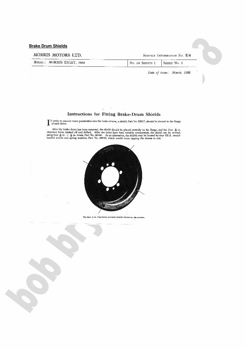
Brake Drum Shields
Regarding brake drum skimming I had a 1.0 mm approx. skim on mine to remove score marks and rust, the resultant diameter was therefore 2mm greater than standard. Richard Fuller had a similar job done to a slightly greater depth, and he was informed that this left just enough metal for a further light skim. Whilst this cannot be taken as advice or recommendation of any kind, it seems that if your drum diameter exceeds 8” (203mm) plus 2mm you would be wise not to use them. Failures due to overskimming are known to have occurred. Important Note. I have recently had sent to me an official Ferodo Manual which recommends that the maximum increase of drum diameter after skimming is 0.060” or 1.524mm. It also indicates that it is recommended that oversize linings, or lining shims, are used if the drums have been skimmed.
For those who are still here (!) I hope this has been useful. I would be very pleased to hear any thoughts or constructive criticism should anyone consider my interpretation to be wrong in any way. Further amendments or additions could then be made as necessary. See also article ‘Silicone Brake Fluid and Overhauling Brakes’. BOB BRYAN 2010