M/50100, M/50200 Clamping cylinders - IMI...
24
1-034 8 M5 4 M/50108/* 4 M/50208/* CO2250405 CO2470405 12 M5 6 M/50112/* 5 M/50212/* CO2250405 CO2470405 20 M5 10 M/50120/* 10 M/50220/* CO2250405 CO2470405 32 G1/8 16 M/50132/* 12 M/50232/* CO2250618 CO2470628 50 G1/4 20 M/50150/* 16 M/50250/* CO2250628 CO2470628 63 G1/4 20 M/50163/* 16 M/50263/* CO2250628 CO2470628 * Insert stroke length in mm Other fittings are available, please see section 7 Enable high thrusts to be achieved in restricted space Neat, clean appearance One-piece body construction TECHNICAL DATA Medium: Compressed air, filtered and lubricated Operating pressure: 2 ... 10 bar (single acting) 1,5 ... 10 bar (double acting) Operating temperature: -10°C ... +70°C Consult our Technical Service for use below +2°C MATERIALS Piston rod: stainless steel (austenitic) Body: anodized aluminium Seals: nitrile rubber M/50100, M/50200 Clamping cylinders Single and double acting - Ø 8 ... 63 mm MODELS MODELS Ø Port size Piston rod Ø Single acting Piston rod Ø Double acting STANDARD MODELS Standard strokes 8 • 12 • • 20 • • 32 • • • 50 • • 63 • • Other stroke lengths are not available Ø 4 5 10 25 Single acting Double acting ACCESSORIES Straight fitting Elbow fitting Tube diameter in bold Theoretical forces MODELS Theoretical forces (N) MODELS Theoretical forces (N) at 6 bar at 6 bar Outstroke F 1 Outstroke F 1 M/50108/4 25 3,4 M/50132/10 445 22,3 M/50112/4 55 5,6 M/50132/25 445 13,7 M/50112/10 55 5,4 M/50150/10 1100 36,3 M/50120/4 165 13,2 M/50150/25 1100 25,5 M/50120/10 165 9,6 M/50163/10 1760 52,5 M/50132/5 445 25,2 M/50163/25 1760 41,1 F1 = Return force of spring www.norgren.com/info/en1-034 For further information
Transcript of M/50100, M/50200 Clamping cylinders - IMI...

1-034
8 M5 4 M/50108/* 4 M/50208/* CO2250405 CO2470405
12 M5 6 M/50112/* 5 M/50212/* CO2250405 CO2470405
20 M5 10 M/50120/* 10 M/50220/* CO2250405 CO2470405
32 G1/8 16 M/50132/* 12 M/50232/* CO2250618 CO2470628
50 G1/4 20 M/50150/* 16 M/50250/* CO2250628 CO2470628
63 G1/4 20 M/50163/* 16 M/50263/* CO2250628 CO2470628
* Insert stroke length in mm Other fittings are available, please see section 7
Enable high thrusts to be achievedin restricted space
Neat, clean appearance
One-piece body construction
TECHNICAL DATAMedium:
Compressed air, filtered andlubricated
Operating pressure:
2 ... 10 bar (single acting)
1,5 ... 10 bar (double acting)
Operating temperature:
-10°C ... +70°CConsult our Technical Service for use below +2°C
MATERIALSPiston rod: stainless steel(austenitic)
Body: anodized aluminium
Seals: nitrile rubber
M/50100, M/50200 Clamping cylindersSingle and double acting - Ø 8 ... 63 mm
MODELS MODELS
Ø Port size
Pistonrod Ø
Single acting
Piston rod Ø
Doubleacting
STANDARD MODELS
Standard strokes
8 •
12 • •
20 • •
32 • • •
50 • •
63 • •
Other stroke lengths are not available
Ø 4 5 10 25
Single acting
Double acting
ACCESSORIES
Straightfitting
Elbowfitting
Tube diameter in bold
Theoretical forces
MODELS Theoretical forces (N) MODELS Theoretical forces (N) at 6 bar at 6 barOutstroke F 1 Outstroke F 1
M/50108/4 25 3,4 M/50132/10 445 22,3
M/50112/4 55 5,6 M/50132/25 445 13,7
M/50112/10 55 5,4 M/50150/10 1100 36,3
M/50120/4 165 13,2 M/50150/25 1100 25,5
M/50120/10 165 9,6 M/50163/10 1760 52,5
M/50132/5 445 25,2 M/50163/25 1760 41,1
F1 = Return force of spring
www.norgren.com/info/en1-034
For further information

1-035
M
B
ø J
P
Y
E
D
ø H
A
G
ø L
1 +
F
#
N
1
K
ø C
X
ø H
T
B
F
E
A
D
ø L
1 +G
Y
O
G
ø J
M
#
N
2
2
1
BASIC DIMENSIONSM/50108 ... M/50112 M/50120 ... M/50163
MODELS Ø A B Ø C D E F G Ø H Ø J K Ø L M N O P T X
M/50108/. 8 20 18 – 11 13,5 8 5 6 3,4 – 4 3,2 M 5 – 5 – – –
M/50112/. 12 25 20 – 13 16 9 5 6 3,4 – 5 3,4 M 5 – 4,5 – – –
M/50120/. 20 40 32 5,3 20 24 15 5 10 5,5 M 5 10 5,5 M 5 – 4,5 8 8 2
M/50132/. 32 55 45 6,4 32 32 18 10 10 5,5 M 6 12 5,5 G 1/8 20 – 10 14,5 2,5
M/50150/. 50 80 65 8,4 50 47,5 25 12 11 6,6 M 8 16 6,8 G 1/4 30 – 13 15 3
M/50163/. 63 90 80 8,4 62 50 31 12 15 9 M 8 16 9 G 1/4 30 – 13 15 3
MODELS Ø Y kg
M/50108/4 8 4 15 0,02
M/50112/4 12 4 15 0,03
M/50112/10 12 10 23 0,04
M/50120/4 20 4 20 0,10
M/50120/10 20 10 26 0,10
M/50132/5 32 5 26 0,22
M/50132/10 32 10 31 0,25
M/50132/25 32 25 46 0,31
M/50150/10 50 10 30 0,50
M/50150/25 50 25 45 0,60
M/50163/10 63 10 35 0,80
M/50163/25 63 25 50 1,05
2
1
# Stroke
Exhaust position, do not obstruct
Ø 20 and 32 mm without bores
Standardstrokes

M
B
ø J
N
G
Y
E
D
ø H
A
G
ø L
Z
F
1
K
ø C
X
ø H
T
B
F
E
A
D
ø L
ZG
Y
O
G
N
1
ø JM
2
2
1-036
BASIC DIMENSIONSM/50208 ... M/50212 M/50220 ... M/50263
2 Ø 20 and 32 mm without bores
MODELS Ø A B Ø C D E F G Ø H Ø J K Ø L M N O T X
M/50208/. 8 20 18 – 11 13,5 8 5 6 3,4 – 4 3,2 M 5 – – – –
M/50212/. 12 25 20 – 13 16 9 5 6 3,4 – 5 3,4 M 5 – – – –
M/50220/. 20 40 32 5,3 20 24 15 5 10 5,5 M 5 10 5,5 M 5 – 8 8 2
M/50232/. 32 55 45 6,4 32 32 18 10 10 5,5 M 6 12 5,5 G 1/8 20 10 14,5 2,5
M/50250/. 50 80 65 8,4 50 47,5 – 12 11 6,6 M 8 16 6,8 G 1/4 30 13 15 3
M/50263/. 63 90 80 8,4 62 50 – 12 15 9 M 8 16 9 G 1/4 30 13 15 3
MODELS Ø Y Z kg
M/50208/4 8 4 22 5 0,03
M/50208/10 8 10 28 11 0,03
M/50212/4 12 4 24 5 0,04
M/50212/10 12 10 30 11 0,05
M/50220/4 20 4 25 8 0,10
M/50220/10 20 10 31 14 0,11
M/50232/5 32 5 33,5 10 0,25
M/50232/10 32 10 38,5 15 0,30
M/50232/25 32 25 53,5 30 0,42
M/50250/10 50 10 36,5 15 0,60
M/50250/25 50 25 51,5 30 0,68
M/50263/10 63 10 41,5 15 0,90
M/50263/25 63 25 56,5 30 1,16
M/50100, M/50200 Clamping cylindersSingle and double acting - Ø 8 ... 63 mm
Standardstrokes

1-037www.norgren.com/info/en1-037
For further information
20 10 M5 RM/91020/M/* M/50/LSU/5V M/P72487 C02250405 C02470405 –
25 12 M5 RM/91025/M/* M/50/LSU/5V M/P72487 C02250405 C02470405 –
32 16 G1/8 RM/91032/M/* M/50/LSU/5V M/P72487 C02250618 C02470618 –
40 16 G1/8 RM/91040/M/* M/50/LSU/5V M/P72487 C02250618 C02470618 –
50 20 G1/8 RM/91050/M/* M/50/LSU/5V M/P72487 C02250618 C02470618 QM/92050/00
63 20 G1/4 RM/91063/M/* M/50/LSU/5V M/P72487 C02250628 C02470628 QM/92063/00
*Insert stroke length in mm For information on additional magnetic switches see page 1-290
Other fittings are available, please see section 7
One third the basic length of acorresponding ISO/VDMA model
Low friction, long life seal design
Non-corrosive specification - givesconsistency with other ranges
Standard magnetic piston
TECHNICAL DATAMedium:
Compressed air, filtered,
lubricated or non-lubricated
Operation:
Single acting, non-cushioned,magnetic piston sprung in
Operating pressure:
2 ... 10 bar
Operating temperature:
+80°CConsult our Technical Service for use below +2°C
MATERIALSBarrel and end caps: anodizedaluminium alloy
Piston rod: stainless steel (Ø12 ... 40 mm Austenitic, Ø 50 and 63 mmMartensitic)
Seals: polyurethane and/or nitrilerubber
RM/91000/M Short stroke cylindersSingle acting - Ø 20 ... 63 mm
STANDARD MODELS
20 •
25 •
32 • •
40 • •
50 • •
63 • •
Ø 10 25
Standard strokes
MODELS ACCESSORIES
Ø Pistonrod Ø
Port size
Femalethreadsprung in
Reed switchwith integral 5 mcable
Switch mounting
Straightfitting
Elbowfitting
Servicekit
Tube diameter in bold
Theoretical forces
Cylinder Theoretical forces (N) at 6 bar
Ø outstroke F1
12 57 7
16 103 12,5
20 161 14,5
25 264 20
32 432 32
40 687 44
50 1094 56,5
63 1770 74,5
F1 = Return force of spring (N)

MOUNTINGS
Ø B,G C F N Stud or Adapter*
20 QM/90020/22 QM/90020/21 QM/92020/25 M/P1501/109 M/P1710/20
25 QM/90025/22 QM/90025/21 QM/57016/25 M/P1501/79 M/P1710/21
32 QM/90032/22 QM/90032/21 QM/57020/25 M/P1501/60 M/P1710/22
40 QM/90040/22 QM/90040/21 QM/57020/25 M/P1501/60 M/P1710/22
50 QM/90050/22 QM/90050/21 QM/57025/25 - M/P71470/1
63 QM/90063/22 QM/90063/21 QM/57040/25 - M/P71470/2
* For attaching F mounting to female piston rod thread.For details of mountings see page 1-045.
B
G
C
C
N
F
Switch mounting
Reed switch
Stud orAdapter
OPTIONS SELECTORRM/9★★★★/★★/★★
Strokes (mm)
50max.
Variants (magnetic piston) Substitute
Standard M
Non-rotating piston rod N2
Note: If option is not required, disregard option positionwithin part number eg. RM/91025/M/25. For combinations ofcylinder variants consult our Technical Service. This options selector explains only the cylinder variants. Additional variants/options are not possible.Information about variants see data sheet.
Special variants Substitute
Sprung in 1
Sprung out 3
Cylinder diameters (mm) Substitute
012 012
016 016
020 020
025 025
032 032
040 045
050 050
063 063
Straight fitting
1-038
RM/91000/M Short stroke cylindersSingle acting - Ø 20 ... 63 mm

1-039
BASIC DIMENSIONS
2
1
# Stroke
Port thread with inserted filter, do not obstruct
Only the 4 front holes are tapped on stroke lengths ofless than:Ø 25 and 32 mm: 5 mm, Ø 40 and 63 mm: 15 mmØ 50 mm: 10 mmNote: Ø 12 ... 20 mm feature only two side dovetails.
X
Z
MX
2,7
13
45°
ZJ + # + V
PL PL EE
GB
BG
ZH + # + V
ø F
B
ø J
B
ø M
Mh
9
TG2
FF
øD
RT
E
TG
1
PF
KF
AF
WH
MX 1
ZJ 1 + # + V
ZH 1 + # + V
ZJ 1 + 2 x # +V
ZH 1 + # + V
MX 1
CYLINDER VARIANTSRM/91000/N2 – Cylinders with non–rotating RM/93000/N2 – Cylinders with non–rotating piston rod – sprung in piston rod – sprung out
X
ZJ + 2 x # + V
PL PL
ZH + # + V
WH + # EE *
RM/91000/M (sprung in) RM/93000/M (sprung out)
Ø AF BG Ø D … E EE Ø FB FF GB Ø JB KF Ø MM h9 MX MX1 PF
12 6 9 32,5 25 M 5 3,3 10 3,5 6 M 3 6 5 – 15
16 7 9 36,5 28 M 5 3,3 10 3,5 6 M 4 8 6 6 17
20 8 9 41,5 32 M 5 3,3 10 3,5 6 M 5 10 8 8 19,5
25 9 12 48 37 M 5 4,2 10 4,5 7,5 M 6 12 10 10 22
32 12 12 58 45 G 1/8 4,2 18 4,5 7,5 M 8 16 13 13 27,5
40 12 16 71,5 55 G 1/8 6,8 18 6,5 10,5 M 8 16 13 13 31,5
50 14 16 81 63 G 1/8 6,8 18 6,5 10,5 M 10 20 17 16 37
63 16 20 104 80 G 1/4 8,5 22 8,5 13,5 M 12 20 17 16 48
Ø PL RT TG 1 TG 2 V* WH ZH ZH 1 ZJ ZJ 1 at 0 mm per 5 mm0 ... 25 mm 26 ... 50 mm
12 7 M 4 17 13 14 – 4,5 24 – 28,5 – 0,07 kg 0,02 kg
16 7,5 M 4 20 20 15 – 5,5 24,5 34,5 30 40 0,09 kg 0,02 kg
20 7,5 M 4 23 23 17 34 6 26 36 32 42 0,12 kg 0,02 kg
25 8 M 5 27 27 18 36 6,5 28,5 38,5 35 45 0,17 kg 0,03 kg
32 9 M 5 33 33 19 38 6,5 29 39 35,5 45,5 0,28 kg 0,05 kg
40 10 M 8 41 41 20 40 6,5 31,5 41,5 38 48 0,44 kg 0,06 kg
50 10,5 M 8 48 48 30 60 8 35 45 43 53 0,50 kg 0,08 kg
63 13 M 10 61 61 30 60 8 42,5 52,5 50,5 60,5 0,90 kg 0,11 kg
* Stroke length (mm)

1-040 www.norgren.com/info/en1-040
For further information
MODELS ACCESORIES
Ø Pistonrod Ø
Port size
Magnetic Guided Reed switchwith integral5m cable
Switch
mounting
Banjo flowcontrol
Straightfitting
Elbowfitting
Servicekit
One third the basic length of acorresponding ISO/VDMA model
Low friction, long life seal design
Fully non-corrosive specification -gives consistency with other ranges
Standard magnetic piston for fullcontrol system versatility
TECHNICAL DATAMedium:
Compressed air, filtered, lubricatedor non-lubricated
Operation:
Double acting, magnetic piston non-cushioned
Operating pressure:
1 ... 10 bar
Operating temperature:
+80°C Consult our Technical Service for use below +2°C
MATERIALSBarrel & end caps: anodizedaluminium alloy
Piston rod: stainless steel
(Ø 12 ... 40 mm Austenitic,
Ø 50 ... 100 mm Martensitic)
Seals: polyurethane and/or nitrilerubber
Standard strokes
12 • • • • • •
16 • • • • • •
20 • • • • • • • •
25 • • • • • • • •
32 • • • • • • • • • •
40 • • • • • • • • • •
50 • • • • • • • • • •
63 • • • • • • • • • •
80 • • • • • • • • •
100 • • • • • • • • •
Other strokes available
Ø 5 10 15 20 25 30 40 50 60 80 100
12 6 M5 RM/92012/M/* M/50/LSU/5V M/P72487 C0K510405 C02250405 C02470405 –
16 8 M5 RM/92016/M/* RM/92016/N4/* M/50/LSU/5V M/P72487 C0K510405 C02250405 C02470405 –
20 10 M5 RM/92020/M/* RM/92020/N4/* M/50/LSU/5V M/P72487 C0K510405 C02250405 C02470405 –
25 12 M5 RM/92025/M/* RM/92025/N4/* M/50/LSU/5V M/P72487 C0K510405 C02250405 C02470405 –
32 16 G1/8 RM/92032/M/* RM/92032/N4/* M/50/LSU/5V M/P72487 C0K510618 C02250618 C02470618 –
40 16 G1/8 RM/92040/M/* RM/92040/N4/* M/50/LSU/5V M/P72487 C0K510618 C02250618 C02470618 –
50 20 G1/8 RM/92050/M/* RM/92050/N4/* M/50/LSU/5V M/P72487 C0K510618 C02250618 C02470618 QM/92050/00
63 20 G1/4 RM/92063/M/* RM/92063/N4/* M/50/LSU/5V M/P72487 C0K510628 C02250628 C02470628 QM/92063/00
80 25 G1/4 RM/92080/M/* RM/92080/N4/* M/50/LSU/5V M/P72487 C0K510628 C02250628 C02470628 QM/92080/00
100 25 G1/4 RM/92100/M/* RM/92100/N4/* M/50/LSU/5V M/P72487 C0K510628 C02250628 C02470628 QM/92100/00
*Insert stroke length in mm For information on additional magnetic switches see page 1-290
Other fittings are available, please see section 7
STANDARD MODELS
RM/92000/M Short stroke cylindersDouble acting - Ø 12 ... 100 mm
Tube diameter in bold

1-041
OPTIONS SELECTOR★RM/92★★★/★★/★★★
Strokes (mm)
Ø 16 ... 25 max. 200
Ø 32 ... 40 max. 250
Ø 50 ... 100 max. 300
Variants (magnetic piston) Substitute
Standard M
Non-rotating piston rod N2
Guided piston rod N4
Double ended piston rod JM
Extended piston rod MU
RM92***/MU/***/***
Extension (mm)
Note: If option is not required, disregard option positionwithin part number eg. RM/92100/M/100. For combinationsof cylinder variants consult our technical service.Please note that heat resistant seals are not available for all variants.This options selector explains only the cylinder variants.Additional variants/options can not be derived from.Information about variants see data sheet.
Special variants Substitute
Heat resistant seals, 150°C max. T
Cylinder diameters (mm) Substitute
012 012
016 016
020 020
025 025
032 032
040 045
050 050
063 063
080 080
100 100
Ø B,G C F N Stud or Adapter*
12 QM/90012/22 QM/90012/21 QM/57008/25 M/P1500/111 M/P1710/18
16 QM/90016/22 QM/90016/21 QM/8010/25 M/P1501/80 M/P1710/1
20 QM/90020/22 QM/90020/21 QM/92020/25 M/P1501/109 M/P1710/20
25 QM/90025/22 QM/90025/21 QM/57016/25 M/P1501/79 M/P1710/21
32 QM/90032/22 QM/90032/21 QM/57020/25 M/P1501/60 M/P1710/22
40 QM/90040/22 QM/90040/21 QM/57020/25 M/P1501/60 M/P1710/22
50 QM/90050/22 QM/90050/21 QM/57025/25 – M/P71470/1
63 QM/90063/22 QM/90063/21 QM/57040/25 – M/P71470/2
80 QM/90080/22 QM/90080/21 QM/57063/25 – M/P71470/3
100 QM/90100/22 QM/90100/21 QM/57063/25 – M/P71470/3
*For attaching F mounting to female piston rod thread
B
G
C
C
N
F
Switch mounting
Reed switch
Stud or Adapter
Banjo
MOUNTINGS

X
Z
MX
Z
2,7
13
45°
X
ZJ + #
PL PL EE EE
GB
BG
ZH + #
ø F
B
ø J
B
ø M
Mh
9
TG2
FF
øD
RT
E
TG
1
PF
KF
AF
WH
2
1
1-042
BASIC DIMENSIONS
MODELS Ø AF BG Ø D … E EE Ø FB FF GB Ø JB KF Ø MM h9 MX
RM/92012/. 12 6 9 32,5 25 M 5 3,3 10 3,5 6 M 3 6 5
RM/92016/. 16 7 9 36,5 28 M 5 3,3 10 3,5 6 M 4 8 6
RM/92020/. 20 8 9 41,5 32 M 5 3,3 10 3,5 6 M 5 10 8
RM/92025/. 25 9 12 48 37 M 5 4,2 10 4,5 7,5 M 6 12 10
RM/92032/. 32 12 12 58 45 G 1/8 4,2 18 4,5 7,5 M 8 16 13
RM/92040/. 40 12 16 71,5 55 G 1/8 6,8 18 6,5 10,5 M 8 16 13
RM/92050/. 50 14 16 81 63 G 1/8 6,8 18 6,5 10,5 M 10 20 17
RM/92063/. 63 16 20 104 80 G 1/4 8,5 22 8,5 13,5 M 12 20 17
RM/92080/. 80 22 20 120 94 G 1/4 8,5 22 8,5 13,5 M 16 25 22
RM/92100/. 100 22 25 148,5 116,5 G 1/4 10,2 22 10,5 16,5 M 16 25 22
MODELS Ø PF PL RT TG1 TG2 WH ZH ZH* ZJ ZJ * at 0 mm per 5 mm
RM/92012/. 12 15 7 M 4 17 13 4,5 24 34 28,5 38,5 0,06 kg 0,04 kg
RM/92016/. 16 17 7,5 M 4 20 20 5,5 24,5 34,5 30 40 0,08 kg 0,04 kg
RM/92020/. 20 19,5 7,5 M 4 23 23 6 26 36 32 42 0,10 kg 0,06 kg
RM/92025/. 25 22 8 M 5 27 27 6,5 28,5 38,5 35 45 0,15 kg 0,07 kg
RM/92032/. 32 27,5 9 M 5 33 33 6,5 29 39 35,5 45,5 0,25 kg 0,12 kg
RM/92040/. 40 31,5 10 M 8 41 41 6,5 31,5 41,5 38 48 0,38 kg 0,15 kg
RM/92050/. 50 37 10,5 M 8 48 48 8 35 45 43 53 0,45 kg 0,18 kg
RM/92063/. 63 48 13 M 10 61 61 8 42,5 52,5 50,5 60,5 0,82 kg 0,26 kg
RM/92080/. 80 57 14,5 M 10 73 73 9 47 57 56 66 1,20 kg 0,33 kg
RM/92100/. 100 67 16 M 12 90,5 90,5 10 48,5 58,5 58,5 68,5 1,83 kg 0,42 kg
RM/92000/M – Standard
2
1
# Stroke
Only the 4 front holes are tapped on stroke lengths of less than: Ø 25 and 32 mm: 5 mm, Ø 40 and 63 mm: 15 mm (.../N2: 5 mm), Ø 50 and 80 mm: 10 mm, Ø 100 mm: 25 mm (.../N2: 15 mm)
Note: Ø 12 ... 20 mm feature only two side dovetails
* for stroke > 50 mm
RM/92000/M Short stroke cylindersDouble acting - Ø 12 ... 100 mm

1-043
ZJ 2 + #
ZM + 2 x #
ZH 2 + #
MX 1
ZJ 1 + #
ZH 1 + #
CYLINDER VARIANTSRM/92000/JM – Cylinders with double ended piston rod RM/92000/N2 – Cylinders with non-rotating piston rod
MODELS Ø ZH2 ZJ2 ZM
RM/92016/JM 16 29,5 35 41
RM/92020/JM 20 31,5 37,5 44
RM/92025/JM 25 34,5 41 48
RM/92032/JM 32 36,5 43 50
RM/92040/JM 40 39,5 46 53
RM/92050/JM 50 42 50 59
RM/92063/JM 63 52 60 69
RM/92080/JM 80 56 65 74
RM/92100/JM 100 58 68 78
MODELS Ø MX1 ZH1 ZJ1 Torque max.
RM/92016/N2 16 6 34,5 40 0,15 Nm
RM/92020/N2 20 8 36 42 0,25 Nm
RM/92025/N2 25 10 38 45 0,40 Nm
RM/92032/N2 32 13 39 45,5 0,75 Nm
RM/92040/N2 40 13 41,5 48 0,75 Nm
RM/92050/N2 50 16 45 53 1,50 Nm
RM/92063/N2 63 16 52,5 60,5 1,50 Nm
RM/92080/N2 80 21 57 66 2,50 Nm
RM/92100/N2 100 21 58,5 68,5 2,50 Nm
# Stroke

10
0
20
30
25
15
5
0 10 30 50 70 90 100
ø 25
ø 20
ø 16
0,1
0,2
0
0,3
0,4
0,5
0 10 30 50 70 90 100
ø 25
ø 20
ø 16
0,6
0,7
10
20
0
30
40
60
80
70
0 10 30 50 70 90 100
ø 100
ø 80
ø 50
ø 40
ø 32
ø 63
50
90
100
1
2
0
3
4
5
0 10 30 50 70 90 100
ø 100
ø 80
ø 63
ø 50
ø 40ø 32
6
7
1-044
TT
TG HF
WH PL PL
GB
ZJ + #
ZH + #
C
H
BG FB
RT
JB
Z
2,7
13
45°
FF
EE
E
PF
øD
Z
RM/92000/N4 – Cylinder with guide piston rod
MODELS Ø BG C Ø D … E EE Ø FB FF GB … H HF Ø JB
RM/92016/N4 16 9 21 36,5 28 M 5 3,3 10 3,5 26,5 6 6
RM/92020/N4 20 9 25 41,5 32 M 5 3,3 10 3,5 30 8 6
RM/92025/N4 25 12 29,5 48 37 M 5 4,2 10 4,5 35 8 7,5
RM/92032/N4 32 12 38 58 45 G 1/8 4,2 18 4,5 43 10 7,5
RM/92040/N4 40 16 46,5 71,5 55 G 1/8 6,8 18 6,5 52 10 10,5
RM/92050/N4 50 16 56,5 81 63 G 1/8 6,8 18 6,5 60 12 10,5
RM/92063/N4 63 20 71 104 80 G 1/4 8,5 22 8,5 76 12 13,5
RM/92080/N4 80 20 89 120 94 G 1/4 8,5 22 8,5 90 16 13,5
RM/92100/N4 100 25 110 148,5 116,5 G 1/4 10,2 22 10,5 113 20 16,5
MODELS PF PL RT … TG TT WH ZH ZH* ZJ ZJ * at 0 mm per 25 mm
RM/92016/N4 17 7,5 M 4 20 M 3 11,5 24,5 24,5 36 36 0,110 kg 0,050 kg
RM/92020/N4 19,5 7,5 M 4 23 M 3 14 26 36 40 50 0,130 kg 0,070 kg
RM/92025/N4 22 8 M 5 27 M 4 14,5 28,5 38,5 43 53 0,170 kg 0,100 kg
RM/92032/N4 27,5 9 M 5 33 M 4 16,5 29 39 45,5 55,5 0,280 kg 0,130 kg
RM/92040/N4 31,5 10 M 8 41 M 5 16,5 31,5 41,5 48 58 0,440 kg 0,150 kg
RM/92050/N4 37 10,5 M 8 48 M 6 20 35 45 55 65 0,500 kg 0,200 kg
RM/92063/N4 48 13 M 10 61 M 8 20 42,5 52,5 62,5 72,5 0,900 kg 0,300 kg
RM/92080/N4 57 14,5 M 10 73 M 10 25 47 57 72 82 1,350 kg 0,350 kg
RM/92100/N4 67 16 M 12 90,5 M 12 30 48,5 58,5 78,5 88,5 2,200 kg 0,600 kg
* for stroke > 50 mm
RM/92000/N4 – Cylinder with guide piston rodSide load
F – Side load (N) M – Torque (Nm) F – Side load (N) F – Side load (N)
Permissible load and torque
F F
M
RM/92000/M Short stroke cylindersDouble acting - Ø 12 ... 100 mm
Outstroke (mm) Stroke (mm) Outstroke (mm) Stroke (mm)

1-045
E
R
FB
TF
UF
MFFront flange – GRear flange – B
MOUNTINGS - For RM/91000/M & RM/92000/M
CE
LE
CL
ER
KK
ø C
K h
11
RK
CL
CMA
T
DG
UL
AH
ø DB
H AO ø AB
TR
Foot – C
MODELS Ø E R Ø FB MF TF UF kg
QM/90012/22 12 26 18 3,5 5 38 46 0,02
QM/90016/22 16 30 22 3,5 5 42 50 0,02
QM/90020/22 20 33 25 3,5 5 48 56 0,02
QM/90025/22 25 38 28 4,5 6,5 54 64 0,04
QM/90032/22 32 46 36 4,5 6,5 66 76 0,06
QM/90040/22 40 57 43 6,5 9,5 78 92 0,15
QM/90050/22 50 64 50 6,5 9,5 90 104 0,17
QM/90063/22 63 81 63 9,5 12,5 110 128 0,33
QM/90080/22 80 95 77 8,5 12,5 128 146 0,41
QM/90100/22 100 118 98 11 12,5 156 176 0,72
MODELS Ø Ø AB AH AO AT H
QM/90012/21 12 3,4 13,5 4 9,5 2
QM/90016/21 16 3,4 15 4 9,5 2
QM/90020/21 20 3,4 16,5 4 9,5 2
QM/90025/21 25 4,3 20 5 12,5 3
QM/90032/21 32 4,3 23 5 12,5 3
QM/90040/21 40 6,4 28,5 6,5 16 4,5
QM/90050/21 50 6,4 32 6,5 16 4,5
QM/90063/21 63 8,4 41,5 8 22 5,5
QM/90080/21 80 8,4 49 8 25,5 5,5
QM/90100/21 100 10,5 59,5 9, 28,5 6,5
MODELS Ø Ø DB DG TR UL kg
QM/90012/21 12 6 3,5 25 33 0,02
QM/90016/21 16 6 3,5 32 40 0,02
QM/90020/21 20 6 3,5 35 43 0,02
QM/90025/21 25 7,5 4,5 41 51 0,04
QM/90032/21 32 7,5 4,5 19 46 0,04
QM/90040/21 40 10,5 6,5 21 56 0,10
QM/90050/21 50 10,5 6,5 27 64 0,11
QM/90063/21 63 13,5 8,5 34 81 0,13
QM/90080/21 80 13,5 8,5 44 95 0,18
QM/90100/21 100 16,5 10,5 56 118 0,48
Piston rod clevis – F
A
B KW
KF
KV
KK
Adaptor
MODELS Ø KK CE Ø CKh11 CL CM ER LE RK kg
QM/57008/25 12 M3 11 3 h9 6 3 4,5 5 10 0,01
QM/8010/25 16 M4 16 4 8 4 6,5 8 11,5 0,01
QM/92020/25 20 M5 20 5 10 5 8 10 14,5 0,01
QM/57016/25 25 M6 20 5 10 5 8 10 14,5 0,01
QM/57020/25 32 & 40 M8 24 6 12 6 9,5 12 17,5 0,02
QM/57025/25 50 M10x1,25 26 8 14 7 11,5 12 20,5 0,04
QM/57040/25 63 M12x1,25 40 10 20 11 16 20 29 0,09
QM/57063/25 80 &100 M16x1,5 56 14 27 14 21 28 36,5 0,22
MODELS Ø A B KF KK KV KW kg
M/P71470/1 50 29 12 M10 M10x1,25 12 5 0,02
M/P71470/1 63 35 15 M12 M12x1,25 13 5 0,04
M/P71470/1 80 & 100 45 20 M16 M16x1,5 17 5 0,08
K W K F
MODELS Ø KF KW kg
M/P1500/111 12 M3 2 6 0,01
M/P1501/80 16 M4 2 7 0,01
M/P1501/109 20 M5 2,5 8 0,01
M/P1501/79 25 M6 3 10 0,01
M/P1501/60 32 & 40 M8 4 13 0,01
A
KF
Stud
MODELS Ø A KF kg
M/P1710/18 12 12 M3 0,01
M/P1710/19 16 16 M4 0,01
M/P1710/20 20 20 M5 0,01
M/P1710/21 25 25 M6 0,01
M/P1710/22 32 & 40 25 M8 0,01
Nut - N
Assembly kitL
A - B
MODELS Ø L
QM/90012/55 12 10 7
QM/90016/55 16 10 7
QM/90020/55 20 10 7
QM/90025/55 25 10 8
QM/90032/55 32 10 8
QM/90040/55 40 15 13
QM/90050/55 50 15 13
QM/90063/55 63 20 17
QM/90080/55 80 20 17
QM/90100/55 100 25 19

20 10 M5 RA/191020/MX/* RA/193020/MX/* RA/191020/M/* RA/193020/M/* M/50/LSU/5V C02250405 C02470405
25 10 M5 RA/191025/MX/* RA/193025/MX/* RA/191025/M/* RA/193025/M/* M/50/LSU/5V C02250405 C02470405
32 12 G1/8 RA/191032/MX/* RA/193032/MX/* RA/191032/M/* RA/193032/M/* M/50/LSU/5V C02250618 C02470618
40 16 G1/8 RA/191040/MX/* RA/193040/MX/* RA/191040/M/* RA/193040/M/* M/50/LSU/5V C02250618 C02470618
50 20 G1/8 RA/191050/MX/* RA/193050/MX/* RA/191050/M/* RA/193050/M/* M/50/LSU/5V C02250618 C02470618
63 20 G1/8 RA/191063/MX/* RA/193063/MX/* RA/191063/M/* RA/193063/M/* M/50/LSU/5V C02250618 C02470618
*Insert stroke length in mm For information on additional magnetic switches
see page 1-290
Other fittings are available, please see section 7
Sprung Out
MODELS MODELS ACCESSORIES
Ø Pistonrod Ø
Port size
Female threadSprung in Sprung out
Male threadSprung in Sprung out
Reed switchwith integral 5m cable
Straightfitting
Elbowfitting
STANDARD MODELS
20 • •
25 • •
32 • •
40 • •
50 • •
63 • •
Standard strokes
Ø 5 10 25
Sprung In
Tube diameter in bold
Theoretical forces
RA/191000/M RA/193000/M EnergyTheoretical forces (N) at 6 bar Theoretical forces (N) at 6 bar (J)
Ø Outstroke F1 Instroke F1 max.
20 161 14,5 119 14,5 0,20
25 264 20 197 20 0,30
32 432 32 311 32 0,45
40 687 44 566 44 0,75
50 1043 56,5 906 56,5 1,10
63 1770 74,5 1582 74,5 1,30
F1 = Return force of spring
1-046 www.norgren.com/info/en1-046
For further information
Conforms to ISO21287
Magnetic piston as standard
Low friction, long life seals
Switches can be mounted flushwith the profile
TECHNICAL DATAMedium:
Compressed air, filtered, lubricatedor non-lubricated
Operating pressure:
2 ... 10 bar
Operating temperature:
-5°C ... +80°CConsult our Technical Service for use below +2°C
MATERIALSProfile barrel: anodized aluminium
End covers: pressure diecastaluminium
Piston rod: stainless steel
Piston rod seals: polyurethane
Piston seals: nitrile rubber
O-rings: nitrile rubber
RA/191000/MX,.../M; RA/193000/MX,…/M Compact cylindersSingle acting, ISO 21287- Ø 20 ... 63 mm

A
A
C
C
D2
FH
FH
L2
S
S
UH
UH
AK
F
N2
UF
US
B,G
B,G
D
URSW
R
1-047
OPTIONS SELECTOR ★A/19★★★★/★★★/★★
Cylinder diameters (mm) Substitute
20 020
25 025
32 032
40 040
50 050
63 063
Strokes (mm)
50 max.
Note: If option is not required, disregard option positionwithin part number eg. RA/191032/M/25. For combinations ofcylinder variants consult our technical service.This options selector explains only the cylinder variants.Additional variants/options can not be derived from.Information about variants see data sheet.
Variants (magnetic piston) Substitute
Standard M
Non-rotating piston rod N2
Extended piston rod MU
RA/19****/MU*/**/***
Extension (mm)
Piston rod thread Substitute
Female X
Male None
Operation Substitute
Sprung in 1
Sprung out 3
Piston rod materials Substitute
Stainless steel martensitic (1.4021) R
Stainless steel austenitic (1.4305) S
A
A
B,G
B,G
C
C
D
D2
FH
FH
L2
R
S
S
SW
UH
UH
URUS
Ø A B, G C D D2 FH L220 – QA/192020/22 QM/192020/21 – – – QM/8020/44
25 – QA/192025/22 QM/192025/21 – – – QM/8020/44
32 QM/8032/35 QA/8032/22 QA/192032/21 QA/8032/23 QA/8032/42 QA/8032/34 –
40 QM/8032/35 QA/8040/22 QA/192040/21 QA/8040/23 QA/8040/42 QA/8040/34 –
50 QM/8050/35 QA/8050/22 QA/192050/21 QA/8050/23 QA/8050/42 QA/8050/34 –
63 QM/8050/35 QA/8063/22 QA/192063/21 QA/8063/23 QA/8063/42 QA/8063/34 –
Ø R S SW UH UR US20 QM/192020/27 – – – – –
25 QM/192025/27 – – – – –
32 QA/8032/27 QA/8032/41 M/P19493 PQA/182032/40 QA/8032/33 M/P40310
40 QA/8040/27 QA/8040/41 M/P19494 PQA/182040/40 QA/8040/33 M/P40311
50 QA/8050/27 QA/8040/41 M/P19495 PQA/182050/40 QA/8050/33 M/P40312
63 QA/8063/27 QA/8063/41 M/P19496 PQA/182063/40 QA/8063/33 M/P40313
MOUNTINGS
Ø AK F N2 UF20 QM/8020/38 QM/8020/25 M/P1501/60 QM/8020/32
25 QM/8020/38 QM/8020/25 M/P1501/60 QM/8020/32
32 QM/8025/38 QM/8025/25 M/P1501/89 QM/8025/32
40 QM/8025/38 QM/8025/25 M/P1501/89 QM/8025/32
50 QM/8040/38 QM/8040/25 M/P1501/90 QM/8040/32
63 QM/8040/38 QM/8040/25 M/P1501/90 QM/8040/32
For details of mountings see page 1-092
For cylinders with male piston rod thread
For cylinders with male and female piston rod thread
RA/191000/M - RA/193000/M
RA/191000/MX - RA/193000/MX
Reed switch
Reed switch
1-048
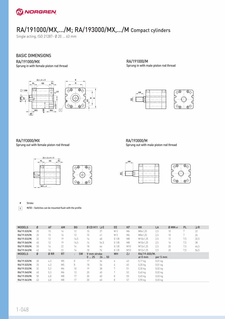
RA/191000/MXSprung in with female piston rod thread
RA/191000/MSprung in with male piston rod thread
Ø M
M h
9
AF
KF
E
R
ER
RT
ø R
R
EEPL PL
ø C
D H
11
LA
BGWH
ZJ + # + V
SW
1
KK
AM
RA/193000/MX Sprung out with female piston rod thread
RA/193000/MSprung out with male piston rod thread
EEPL PL
WH + #
ZJ + 2 x # + V
KK
AM
BASIC DIMENSIONS
1
# Stroke
M/50 – Switches can be mounted flush with the profile
MODELS Ø AF AM BG Ø CD H11 … E EE KF KK LA Ø MM h9 PL … R
RA/19.020/M. 20 10 16 12 10 37 M 5 M6 M8x1,25 2,5 10 7 22
RA/19.025/M. 25 10 16 13 10 41 M 5 M6 M8x1,25 2,5 10 7 26
RA/19.032/M. 32 12 19 14,5 14 48 G 1/8 M8 M10x1,25 2,5 12 7,5 32,5
RA/19.040/M. 40 12 19 14,5 14 54,5 G 1/8 M8 M10x1,25 2,5 16 7,5 38
RA/19.050/M. 50 16 22 14 18 66 G 1/8 M10 M12x1,25 2,5 20 7,5 46,5
RA/19.063/M. 63 16 22 14 18 76 G 1/8 M10 M12x1,25 2,5 20 7,5 56,5
MODELS Ø Ø RR RT SW V mm stroke WH ZJ RA/19.000/M.0 ... 25 26 ... 50 at 0 mm per 5 mm
RA/19.020/M. 20 4,3 M5 8 17 34 6 43 0,17 kg 0,01 kg
RA/19.025/M. 25 4,3 M5 8 18 36 6 45 0,20 kg 0,01 kg
RA/19.032/M. 32 5,3 M6 10 19 38 7 51 0,30 kg 0,02 kg
RA/19.040/M. 40 5,3 M6 13 20 40 7 52 0,40 kg 0,02 kg
RA/19.050/M. 50 6,8 M8 17 30 60 8 53 0,65 kg 0,03 kg
RA/19.063/M. 63 6,8 M8 17 30 60 8 57 0,90 kg 0,03 kg
RA/191000/MX,.../M; RA/193000/MX,…/M Compact cylindersSingle acting, ISO 21287- Ø 20 ... 63 mm

1-049
MODELS Ø MX1 V* ZH1 ZJ1 RA/19.000/N2.0 ... 25 26 ... 50 at 0 mm per 5 mm
RA/19.020/N2. 20 8 17 34 47 53 0,17 kg 0,01 kg
RA/19.025/N2. 25 8 18 36 49 55 0,20 kg 0,01 kg
RA/19.032/N2. 32 10 19 38 54 61 0,30 kg 0,02 kg
RA/19.040/N2. 40 13 20 40 55 62 0,40 kg 0,02 kg
RA/19.050/N2. 50 16 30 60 55 63 0,65 kg 0,03 kg
RA/19.063/N2. 63 16 30 60 59 67 0,90 kg 0,03 kg
* stroke length (mm)
MODELS Ø Torque max. (Nm)
RA/19.020/N2. 20 0,15
RA/19.025/N2. 25 0,25
RA/19.032/N2. 32 0,40
RA/19.040/N2. 40 0,75
RA/19.050/N2. 50 1,50
RA/19.063/N2. 63 1,50
MX1
ZJ 1 + # + V
ZH 1 + # + V
ZJ 1 + # + V
ZH 1 + # + V
MX1
RA/191000/N2X – Cylinder with non-rotating piston rodSprung in with female piston rod thread
RA/191000/N2 – Cylinder with non-rotating piston rodSprung in with male piston rod thread
MX1
ZJ 1 + 2 x # + V
ZH 1 + # + V
ZJ 1 + 2 x # + V
ZH 1 + # + V
MX1
RA/193000/N2X – Cylinder with non-rotating piston rodSprung out with female piston rod thread
Torque for cylinders RA/19.000/N2.
RA/193000/N2 – Cylinder with non-rotating piston rodSprung out with male piston rod thread
CYLINDER VARIANTS
# Stroke

1-050 www.norgren.com/info/en1-050
For further information
20 10 M5 RA/192020/MX/* RA/192020/M/* M/50/LSU/5V C0K510405 C02250405 C02470405 QM/192020/00
25 10 M5 RA/192025/MX/* RA/192025/M/* M/50/LSU/5V C0K510405 C02250405 C02470405 QM/192025/00
32 12 G1/8 RA/192032/MX/* RA/192032/M/* M/50/LSU/5V C0K510618 C02250618 C02470618 QM/192032/00
40 16 G1/8 RA/192040/MX/* RA/192040/M/* M/50/LSU/5V C0K510618 C02250618 C02470618 QM/192040/00
50 20 G1/8 RA/192050/MX/* RA/192050/M/* M/50/LSU/5V C0K510618 C02250618 C02470618 QM/192050/00
63 20 G1/8 RA/192063/MX/* RA/192063/M/* M/50/LSU/5V C0K510618 C02250618 C02470618 QM/192063/00
80 25 G1/8 RA/192080/MX/* RA/192080/M/* M/50/LSU/5V C0K510818 C02250818 C02470818 QM/192080/00
100 25 G1/8 RA/192100/MX/* RA/192100/M/* M/50/LSU/5V C0K510818 C02250818 C02470818 QM/192100/00
125 32 G1/4 RA/192125/MX/* RA/192125/M/* M/50/LSU/5V C0K510828 C02250828 C02470828 QM/192125/00
*Insert stroke length in mm For information on additional magnetic switches see page 1-290Other fittings are available, please see section 7
STANDARD MODELS
20 • • • • • • • •
25 • • • • • • • •
32 • • • • • • • • • • •
40 • • • • • • • • • • •
50 • • • • • • • • • •
63 • • • • • • • • • •
80 • • • • • • • • •
100 • • • • • • • • •
125 • • • • • • • • •
Standard strokes
Conforms to ISO 21287
Magnetic piston as standard
Low friction, long life seals
Switches can be mounted flushwith the profile
RA/192000/MX, .../M Compact cylindersDouble acting - Ø 20 ... 125 mm
MODELS ACCESSORIES
Ø Pistonrod Ø
Port size
Female thread
Male thread
Reed switchwith integral 5m cable
Banjo flow control
Straightfitting
Elbowfitting
Service kit
Tube diameter in bold
Ø 5 10 15 20 25 30 40 50 60 80 100
TECHNICAL DATAMedium:
Compressed air, filtered, lubricatedor non-lubricated
Operation:
RA/192000/MDouble acting, magnetic piston,male piston rod thread, buffercushioning
RA/192000/MXDouble acting, magnetic piston,female piston rod thread, buffercushioning
Operating pressure:
1 ... 10 bar
Operating temperature:
-5°C ... +80°C max.Consult our Technical Service for use below +2°C
MATERIALSProfile barrel: anodized aluminium
End covers: pressure diecastaluminium
Piston rod: stainless steel
Piston rod seals: polyurethane
Piston seals: nitrile rubber
O-rings: nitrile rubber

1-051
OPTIONS SELECTOR
★★A/192★★★/★★★/★★★
Strokes (mm)
Ø 20 and 25 min. 5 max. 200
Ø 32 and 40 min. 5 max. 300
Ø 50 and 63 min. 10 max. 400
Ø 80 ... 125 min. 15 max. 500
Piston rod thread Substitute
Female X
Male None
Variants (magnetic piston) Substitute
Standard M
Double ended piston rod JM
Non-rotating piston rod (internal) N2
Guiding N4
Special wiper/seal W2
Locking unit L4
External guiding N6
Extended piston rod MU
RA/192***/MU*/***/***
Extension (mm)
low friction X4
Tandem cylinder TM
Multi-positon cylinder SM
RA/192***/SM*/***/***
Rear cylinder stroke
Front cylinder stroke
Note: If option is not required, disregard option positionwithin part number eg. RA/192100/M/100. For combinationsof cylinder variants consult our technical service.Please note that heat resistant seals are not available for allvariants.This options selector explains only the cylinder variants.Additional variants/options can not be derived from.Information about variants see data sheet.
Special variants Substitute
High temperature version: 150°C max. T
Piston rod materials Substitute
Stainless steel martensitic (1.4021) R
Stainless steel austenitic (1.4305) S
Cylinder diameters (mm) Substitute
20 020
25 025
32 032
40 040
50 050
63 063
80 080
100 100
125 125

1-052
G
B
FH
A
F
UF
AK
N2
C
RC
UR
D
L2
SW
D2
FH
A
USS
S
UHUH
Reed switch
Assembly Kit
Banjo
Ø A B, G C D D2 FH L220 – QA/192020/22 QM/192020/21 – – – QM/8020/4425 – QA/192025/22 QM/192025/21 – – – QM/8020/4432 QM/8032/35 QA/8032/22 QA/192032/21 QA/8032/23 QA/8032/42 QA/8032/34 –40 QM/8032/35 QA/8040/22 QA/192040/21 QA/8040/23 QA/8040/42 QA/8040/34 –50 QM/8050/35 QA/8050/22 QA/192050/21 QA/8050/23 QA/8050/42 QA/8050/34 –63 QM/8050/35 QA/8063/22 QA/192063/21 QA/8063/23 QA/8063/42 QA/8063/34 –80 QM/8080/35 QA/8080/22 QA/192080/21 QA/8080/23 QA/8080/42 QA/8080/34 –100 QM/8080/35 QA/8100/22 QA/192100/21 QA/8100/23 QA/8100/42 QA/8100/34 –125 QM/8125/35 QM/8125/22 QM/8125/21 QM/8125/23 QA/8125/42 QA/8125/34 –Ø R S SW UH UR US Assembly Kit20 QM/192020/27 – – – – – QA/192020/5525 QM/192025/27 – – – – – QA/192025/5532 QA/8032/27 QA/8032/41 M/P19493 PQA/182032/40 QA/8032/33 M/P40310 QA/192032/5540 QA/8040/27 QA/8040/41 M/P19494 PQA/182040/40 QA/8040/33 M/P40311 QA/192040/5550 QA/8050/27 QA/8040/41 M/P19495 PQA/182050/40 QA/8050/33 M/P40312 QA/192050/5563 QA/8063/27 QA/8063/41 M/P19496 PQA/182063/40 QA/8063/33 M/P40313 QA/192063/5580 QA/8080/27 QA/8063/41 M/P19497 PQA/182080/40 QA/8080/33 M/P40314 QA/192080/55100 QA/8100/27 QA/8100/41 M/P19498 PQA/182100/40 QA/8100/33 M/P40315 QA/192100/55125 QM/8125/27 QA/8100/41 M/P19499 PQA/182125/40 QM/8125/33 M/P71355 QA/192125/55
RA/192000/M
Ø AK F N2 UF20 QM/8020/38 QM/8020/25 M/P1501/60 QM/8020/3225 QM/8020/38 QM/8020/25 M/P1501/60 QM/8020/3232 QM/8025/38 QM/8025/25 M/P1501/89 QM/8025/3240 QM/8025/38 QM/8025/25 M/P1501/89 QM/8025/3250 QM/8040/38 QM/8040/25 M/P1501/90 QM/8040/3263 QM/8040/38 QM/8040/25 M/P1501/90 QM/8040/3280 QM/8050/38 QM/8050/25 M/P1501/91 QM/8050/32100 QM/8050/38 QM/8050/25 M/P1501/91 QM/8050/32125 QM/8125/38 QM/8125/25 M/P1501/105 QM/8125/32
For cylinders with male and female piston rod thread
For cylinders with male piston rod thread
C
B
C R
UR
D
US
L2
SW
D2
FH
A
FH
S
S
UHUH
G
A
Banjo
MOUNTINGS
Reed switch
Assembly Kit
For details of mountings see page 1-092
RA/192000/MX
RA/192000/MX, .../M Compact cylindersDouble acting - Ø 20 ... 125 mm

1-053
Ø Energy (J) max.20 0,2
25 0,3
32 0,45
40 0,75
50 1,1
63 1,3
80 1,9
100 2,3
125 3,0
MODELS Ø Torque max. (Nm)
RA/192020/N2 20 0,15
RA/192025/N2 25 0,25
RA/192032/N2 32 0,40
RA/192040/N2 40 0,75
RA/192050/N2 50 1,5
RA/192063/N2 63 1,5
RA/192080/N2 80 2,5
RA/192100/N2 100 2,5
X (mm)
N
200
180160140120
100806040
20
00
1020
3040
5060
7080
90100
ø 100
ø 80
ø 50; 63
ø 40ø 20; 25
ø 32
ø 125
X
F
m x g
Side load
RA/192000/M.RA/192000/N2. – Cylinder with non-rotating piston rodSide load
RA/192000/JM – Cylinder with double ended piston rodSide load
RA/192000/N6 – Cylinder with external guidingSide load
For RA/192000/M. For RA/192000/N2
RA/192000/N4 – Cylinder with guidingSide load
X (mm)
N
010
2030
4050
6070
8090
100
300280260240220200180180160140120100806040200
ø 125
ø 100
ø 80
ø 50; 63ø 40
ø 20, 25
ø 32
X
F
m x g
X (mm)
N
100
90807060
50403020
10
00
1020
3040
5060
7080
90100
ø 100
ø 80
ø 50
ø 63ø 40
ø 25
ø 20
ø 32
(Nm)
100
90807060
50403020
10
0100
(mm)
010
2030
4050
6070
8090
ø 100
ø 80ø 50
ø 63
ø 40
ø 25ø 20
ø 32
M
X
F
m x g
100 20 30 40 50 60 70 80 90 100
100908070605040302010
0
N
X
F
m x g
Special variant
TRA/192000: F x 0,5

RA/192000/M With male piston rod thread
Ø M
M h
9
AF
KF
E
R
ER
RT
ø R
R
EEPL PL
ø C
D H
11
LA
BGVD
WH
ø B
d11
ZJ + #
SW
1
KK
AM
BASIC DIMENSIONS
MODELS Ø AF AM Ø Bd11 BG Ø CDH11 E EE KF KK LA Ø MMh9
RA/192020/. 20 10 16 – 12 10 37 M 5 M6 M8x1,25 2,5 10
RA/192025/. 25 10 16 – 13 10 41 M 5 M6 M8x1,25 2,5 10
RA/192032/. 32 12 19 – 14,5 14 48 G 1/8 M8 M10x1,25 2,5 12
RA/192040/. 40 12 19 – 14,5 14 54,5 G 1/8 M8 M10x1,25 2,5 16
RA/192050/. 50 16 22 – 14 18 66 G 1/8 M10 M12x1,25 2,5 20
RA/192063/. 63 16 22 – 14 18 76 G 1/8 M10 M12x1,25 2,5 20
RA/192080/. 80 20 28 – 15,5 23 96 G 1/8 M12 M16x1,5 3 25
RA/192100/. 100 20 28 – 21,5 26 116 G 1/8 M12 M16x1,5 3 25
RA/192125/. 125 30 54 60 20,5 28 142 G 1/4 M20 M27x2 3 32
MODELS Ø PL R Ø RR RT SW VD WH ZJ at 0 mm per 5 mm
RA/192020/. 20 7 22 4,3 M5 8 – 6 43 0,12 kg 0,01 kg
RA/192025/. 25 7 26 4,3 M5 8 – 6 45 0,15 kg 0,01 kg
RA/192032/. 32 7,5 32,5 5,3 M6 10 – 7 51 0,23 kg 0,02 kg
RA/192040/. 40 7,5 38 5,3 M6 13 – 7 52 0,30 kg 0,02 kg
RA/192050/. 50 7,5 46,5 6,8 M8 17 – 8 53 0,46 kg 0,03 kg
RA/192063/. 63 7,5 56,5 6,8 M8 17 – 8 57 0,70 kg 0,03 kg
RA/192080/. 80 7,5 72 8,6 M10 22 – 10 64 1,23 kg 0,04 kg
RA/192100/. 100 10,5 89 8,6 M10 22 – 10 77 2,20 kg 0,05 kg
RA/192125/. 125 10,5 110 10,6 M12 27 4 18 89 3,60 kg 0,07 kg
RA/192000/MX With female piston rod thread
# Stroke1 M/50 switches can be mounted flush with the profile
MODELS Ø ZH ZJ at 0 mm per 5 mm
RA/192020/N2. 20 8 47 53 0,12 kg 0,01 kg
RA/192025/N2. 25 8 49 55 0,15 kg 0,01 kg
RA/192032/N2. 32 10 54 61 0,23 kg 0,02 kg
RA/192040/N2. 40 13 55 62 0,30 kg 0,02 kg
RA/192050/N2. 50 16 55 63 0,46 kg 0,03 kg
RA/192063/N2. 63 16 59 67 0,70 kg 0,03 kg
RA/192080/N2. 80 21 64 74 1,23 kg 0,04 kg
RA/192100/N2. 100 21 77 87 2,20 kg 0,05 kg
ZJ + #
ZH + #
ZJ + #
ZH + #
RA/192000/N2X – Cylinder with non-rotating piston rod RA/192000/N2 – Cylinder with non-rotating piston rod
CYLINDER VARIANTS
Note: The basic length of the RA/192000/N2 version is slightly longer than the standard
# Stroke
1-054
RA/192000/MX, .../M Compact cylindersDouble acting - Ø 20 ... 125 mm

1-055
HF
WH
ZJ2 + #
JB
TT TDH8
TG
H
MODELS Ø H HF Ø JB Ø TDH8 TG TT WH ZJ2 at 0 mm per 5 mm
RA/192020/N4 20 34 8 7,5 4 12 M4 14 51 0,17 kg 0,01 kg
RA/192025/N4 25 38 8 7,5 5 15,6 M5 14 53 0,23 kg 0,01 kg
RA/192032/N4 32 45 10 9 5 19,8 M5 17 61 0,33 kg 0,02 kg
RA/192040/N4 40 51 10 9 5 23,3 M5 17 62 0,45 kg 0,02 kg
RA/192050/N4 50 62,5 12 11 6 29,7 M6 20 65 0,65 kg 0,03 kg
RA/192063/N4 63 72 12 11 6 35,4 M6 20 69 0,95 kg 0,03 kg
RA/192080/N4 80 92 15 15 8 46 M8 25 79 1,70 kg 0,04 kg
RA/192100/N4 100 112 15 15 10 56,5 M10 25 92 3,10 kg 0,05 kg
RA/192000/N4 – Cylinder with guiding
MODELS Ø ZJ ZM at 0 mm per 5 mm
RA/192020/JM. 20 43 49 0,15 kg 0,01 kg
RA/192025/JM. 25 45 51 0,18 kg 0,01 kg
RA/192032/JM. 32 51 58 0,28 kg 0,02 kg
RA/192040/JM. 40 52 59 0,35 kg 0,02 kg
RA/192050/JM. 50 53 61 0,52 kg 0,03 kg
RA/192063/JM. 63 57 65 0,76 kg 0,03 kg
RA/192080/JM. 80 64 74 1,30 kg 0,04 kg
RA/192100/JM. 100 77 87 2,30 kg 0,05 kg
RA/192125/JM. 125 89 107 3,75 kg 0,07 kg
ZJ + #
ZM + 2 x #
ZJ + #
ZM + 2 x #
RA/192000/JMX – Cylinder with double ended piston rod RA/192000/JM – Cylinder with double ended piston rod
# Stroke
# Stroke

1-056
BA
AE
BE
BZ
AU
AX
BS + #
BR + #
AJ
BN
AE
AC AC AB
AN
EE
ZJ + 2 x #
PL PL1+ # PL
1
3 2
EE
ZJ + 2 x #
PL PL1+ # PL
1
3 2
RA/192000/N6 – Cylinder with external guiding
RA/192000/TMX – Tandem cylinder with female piston rod thread
RA/192000/TM – Tandem cylinder with male piston rod thread
MODELS Ø AB AC AE AJ AN AU AX BA BE BN BR BS BZ at 0 mm per 5 mm
RA/192025/N6 25 7,5 30 M5 12 20 37,5 44 30 16 18 39 57 43,5 0,31 kg 0,09 kg
RA/192032/N6 32 7,5 30 M5 12 20 40,5 48,5 30 16 19 44 63 43,5 0,44 kg 0,12 kg
MODELS Ø EE PL PL1 ZJ at 0 mm per 5 mm
RA/192020/TM. 20 M5 7 25,5 68 0,21 kg 0,01 kg
RA/192025/TM. 25 M5 7 26,5 71 0,26 kg 0,01 kg
RA/192032/TM. 32 G 1/8 7,5 30 81 0,39 kg 0,02 kg
RA/192040/TM. 40 G 1/8 7,5 31 83 0,51 kg 0,02 kg
RA/192050/TM. 50 G 1/8 7,5 31 85 0,78 kg 0,03 kg
RA/192063/TM. 63 G 1/8 7,5 36 94 1,21 kg 0,03 kg
RA/192080/TM. 80 G 1/8 7,5 40 104 2,11 kg 0,04 kg
RA/192100/TM. 100 G 1/8 10,5 45,5 122 3,68 kg 0,05 kg
# Standard strokes 25, 50, 75 and 100 mm only
3
2
#
1 Exhaust port Note: Do not cover this area!
Stroke
Pressure »outstroke«
Pressure »instroke«
RA/192000/MX, .../M Compact cylindersDouble acting - Ø 20 ... 125 mm

1-057
EE
ZJ + #1 + #2
PL PL1+ #1 PL
1
3 4 2
EE
ZJ + #1 + #2
PL PL1+ # 1 PL
1
3 4 2
RA/192000/SMX – Multi position cylinder with female piston rod thread
RA/192000/SM – Multi position cylinder with male piston rod thread
MODELS Ø EE PL PL1 ZJ at 0 mm per 5 mm
RA/192020/SM. 20 M5 7 25,5 68 0,21 kg 0,01 kg
RA/192025/SM. 25 M5 7 26,5 71 0,26 kg 0,01 kg
RA/192032/SM. 32 G 1/8 7,5 30 81 0,39 kg 0,02 kg
RA/192040/SM. 40 G 1/8 7,5 31 83 0,51 kg 0,02 kg
RA/192050/SM. 50 G 1/8 7,5 31 85 0,78 kg 0,03 kg
RA/192063/SM. 63 G 1/8 7,5 36 94 1,21 kg 0,03 kg
RA/192080/SM. 80 G 1/8 7,5 40 104 2,11 kg 0,04 kg
RA/192100/SM. 100 G 1/8 10,5 45,5 122 3,68 kg 0,05 kg
EE
AM
ZH + #AB
AN
VD
WH AH
AD
AF
AE
AG
RT
R
E
AK
AL
Ø AJ
E1
ø B
e 1
1
RA/192000/L4X – Cylinder with locking unitfemale piston rod thread
RA/192000/L4 – Cylinder with locking unit male piston rod thread
MODELS Ø AB AD AE AF AG AH Ø AJ AK AL AM AN B e11
RA/192032/L4X 32 32 12 8 40 4,2 48 25 M 5 16 49 8 30
RA/192040/L4X 40 35,5 12 10 46 4,5 55 24 M 5 21 61,5 10 35
RA/192050/L4X 50 49 16 15 54 11,5 70 30 M 6 24 75 12 40
RA/192063/L4X 63 49 15 15 55 7,5 70 38 M 8 32 86 12 45
RA/192080/L4X 80 62 16 16 70 10 90 53 M 8 44 119 16 45
RA/192100/L4X 100 65 18 16 70 10 92 48 M 8 60 119 16 55
RA/192125/L4X 125 85 27 25 95 11 122 65 M 10 75 140 20 60
MODELS Ø E E 1 EE R RT VD WH ZH at 0 mm per 5 mm
RA/192032/L4X 32 48 50 M 5 32,5 M 6 10 16 44 600 N 0,53 kg 0,02 kg
RA/192040/L4X 40 56 58 G 1/8 38 M 6 10 18 45 1000 N 0,70 kg 0,02 kg
RA/192050/L4X 50 68 70 G 1/8 46,5 M 8 12 22 45 1500 N 1,26 kg 0,03 kg
RA/192063/L4X 63 82 85 G 1/8 56,5 M 8 12 20 49 2200 N 1,90 kg 0,03 kg
RA/192080/L4X 80 100 105 G 1/8 72 M 10 20 33 54 5000 N 3,80 kg 0,04 kg
RA/192100/L4X 100 120 130 G 1/8 89 M 10 23 38 67 5000 N 5,90 kg 0,05 kg
RA/192125/L4X 125 140 150 G 1/8 110 M 12 32 65 71 7000 N 10,10 kg 0,07 kg
# Stroke
#2
#1
4
3
2
1 Exhaust port Note: Do not cover this area!
Pressure »outstroke« rear cylinder
Pressure »instroke«
Pressure »outstroke« front cylinder
Stroke front cylinder
Stroke rear cylinder
Note: Stroke (#1) > stroke (#2)
Lockingforces