M00667-03 pdl450 manual rev c-lw-js _9-30-05
42
PDL450 HPB450 User’s Guide Trimble Navigation Ltd. 935 Stewar t Drive Sunnyvale, CA 94085 (408) 481-8000 www.trimble.com PN: 51858-00, Rev C (M0066703)
-
Upload
guilherme-zaramella-betoni -
Category
Documents
-
view
48 -
download
0
Transcript of M00667-03 pdl450 manual rev c-lw-js _9-30-05

7/16/2019 M00667-03 pdl450 manual rev c-lw-js _9-30-05
http://slidepdf.com/reader/full/m00667-03-pdl450-manual-rev-c-lw-js-9-30-05 1/42
PDL450HPB450
User’s Guide
Trimble Navigation Ltd.
935 Stewart DriveSunnyvale, CA 94085(408) 481-8000
www.trimble.com
PN: 51858-00, Rev C(M0066703)

7/16/2019 M00667-03 pdl450 manual rev c-lw-js _9-30-05
http://slidepdf.com/reader/full/m00667-03-pdl450-manual-rev-c-lw-js-9-30-05 2/42
COPYRIGHT AND TRADEMARKS© 2005, Trimble Navigation Limited. All rights reserved.
Trimble, and the Globe & Triangle logo are trademarks of Trimble NavigationLimited, registered in the United States Patent and Trademark Office and in other
countries. TRIMTALK is a trademark of Trimble Navigation Limited.
AutoBase and AutoRover are trademarks of Paci fic Crest Corporation.
All other trademarks are the property of their respective owners.
RELEASE NOTICEThis is the October release (Revision C) of the PDL450 and HPB450 User’s
Guide, part number M00667-03. It applies to the PDL450 and HPB450 radiomodems.
NOTICESClass B Statement – Notice to Users. This equipment has been tested and foundto comply with the limits for a Class B digital device, pursuant to Part 15 of the
FCC rules. These limits are designed to provide reasonable protection against
harmful interference in a residential installation. This equipment generates, uses,and can radiate radio frequency energy and, if not installed and used in
accordance with the instructions, may cause harmful interference to radiocommunication. However, there is no guarantee that interference will not occur in
a particular installation. If this equipment does cause harmful interference toradio or television reception, which can be determined by turning the equipmentoff and on, the user is encouraged to try to correct the interference by one or
more of the following measures:
• Reorient or relocate the receiving antenna.• Increase the separation between the equipment and the receiver.
• Connect the equipment into an outlet on a circuit different from that towhich the receiver is connected.
• Consult the dealer or an experienced radio/TV technician for help.
Changes and modifications not expressly approved by the manufacturer or
registrant of this equipment can void your authority to operate this equipmentunder Federal Communications Commission rules.

7/16/2019 M00667-03 pdl450 manual rev c-lw-js _9-30-05
http://slidepdf.com/reader/full/m00667-03-pdl450-manual-rev-c-lw-js-9-30-05 3/42
iii
Canada
This digital apparatus does not exceed the Class B limits for radio noiseemissions from digital apparatus as set out in the radio interference regulationsof the Canadian Department of Communications.
Le présent appareil numérique n’émet pas de bruits radioélectriques dépassantles limites applicables aux appareils numériques de Classe B prescrites dans le
règlement sur le brouillage radioélectrique édicté par le Ministère desCommunications du Canada.
Europe
This product has been tested and found to comply with the requirements for aClass B device pursuant to European Council Directive 89/336/EEC on EMC,thereby satisfying the requirements for CE Marking and sale within the European
Economic Area (EEA). These requirements are designed to provide reasonableprotection against harmful interference when the equipment is operated in aresidential or commercial environment.
Aus tral ia and New Zealand
This product conforms with the regulatory requirements of the Australian
Communications Authority (ACA) EMC framework, thus satisfying therequirements for C-Tick Marking and sale within Australia and New Zealand.
Taiwan – Battery Recycl ing Requirements
The product contains a removable Lithium-ion battery. Taiwanese regulationsrequire that waste batteries are recycled.

7/16/2019 M00667-03 pdl450 manual rev c-lw-js _9-30-05
http://slidepdf.com/reader/full/m00667-03-pdl450-manual-rev-c-lw-js-9-30-05 4/42
Notice to Our Europ ean Union Customers
For product recycling instructions and more information, please go to
www.trimble.com/ev.shtml.
Recycling in Europe: To recycle Trimble WEEE (Waste Electrical and ElectronicEquipment, products that run on electrical power.), Call +31 497 53 24 30, andask for the "WEEE Associate". Or, mail a request for recycling instructions to:
Trimble Europe BV
c/o Menlo Worldwide LogisticsMeerheide 45
5521 DZ Eersel, NL
The information contained in this document is subject to change without notice.
CAUTIONS AND WARNINGS
Throughout this manual this symbol is used to indicate caution or warning. Please pay particular attention to these items to assuresafe and reliable operation of your radio modem product.

7/16/2019 M00667-03 pdl450 manual rev c-lw-js _9-30-05
http://slidepdf.com/reader/full/m00667-03-pdl450-manual-rev-c-lw-js-9-30-05 5/42
v
This page intentionally left blank.
7/16/2019 M00667-03 pdl450 manual rev c-lw-js _9-30-05
http://slidepdf.com/reader/full/m00667-03-pdl450-manual-rev-c-lw-js-9-30-05 6/42
TABLE OF CONTENTS
Cautions and Warnings.............................................................. iv Introduction .................................................................................1 Welcome .................................................................................1 Scope ......................................................................................1
Features and Benefits.................................................................2 Setting Up The PDL450..............................................................3
Overview of PDL450 Radio Modem ........................................3 PDL450 Setup .........................................................................6 Setting Up The HPB450..............................................................9 Overview of the HPB450 Radio Modem ..................................9 HPB450 System Setup..........................................................13
Tips and Techniques for Best Performance ..............................18 Antenna .................................................................................18 Power Supplies......................................................................18 How to Use AutoRover™ ......................................................18 How to Use AutoBase™........................................................19 Equipment Care.....................................................................20 Error Codes...........................................................................20
FCC Rules and Regulations......................................................23 Licensing Requirements ........................................................23 Equipment Compliances........................................................23 Being Part of the RF community ............................................24
Automatic Station Identification .............................................25 Carrier Sense Multiple Access (CSMA) .................................25
Service and Support..................................................................27 Contacting Trimble Navigation Ltd.........................................27
Appendix A - Safety Information................................................28 Exposure to Radio Frequency Energy ...................................28
Appendix B - Pin-outs and Connectors .....................................30

7/16/2019 M00667-03 pdl450 manual rev c-lw-js _9-30-05
http://slidepdf.com/reader/full/m00667-03-pdl450-manual-rev-c-lw-js-9-30-05 7/42
vii
PDL450 .....................................................................................30 HPB450 .................................................................................30 Antenna .................................................................................30 Appendix C - Technical Specifications ......................................32 General ..................................................................................32 Radio.....................................................................................32 Modem ..................................................................................33 Environmental .......................................................................34
Table of Figures
Figure 1 - PDL450.......................................................................4 Figure 2 - PDL450 Setup ............................................................7 Figure 3 - PDL450 GPS Cable....................................................8 Figure 4 - HPB450 Front Panel...................................................9 Figure 5 - HPB450 Rear Panel..................................................12 Figure 6 - HPB450 System Setup.............................................14 Figure 7 - PDL450 and HPB450 Data/Power Connectors.........31

7/16/2019 M00667-03 pdl450 manual rev c-lw-js _9-30-05
http://slidepdf.com/reader/full/m00667-03-pdl450-manual-rev-c-lw-js-9-30-05 8/42

7/16/2019 M00667-03 pdl450 manual rev c-lw-js _9-30-05
http://slidepdf.com/reader/full/m00667-03-pdl450-manual-rev-c-lw-js-9-30-05 9/42
PDL450/HPB450 User's Guide 1
INTRODUCTION
Welcome
Thank you for purchasing the PDL450 or HPB450 for use withyour survey system. The PDL450 and HPB450 are advanced,high speed, wireless data links that are designed specifically for GPS/RTK applications. Your success in using the PDL450 andHPB450 is our primary goal. We stand behind our products withexpert support and service. Your comments and questions arewelcome.
Scope
This guide provides information concerning the use of PDL450and HPB450 radio modem products for use with Trimble®systems. The PDL450 and HPB450 can function as a base or
repeater radio link system used for GPS and RTK applications.Trimble’s system User's Manual should be referenced for general information concerning radio and GPS equipmentintegration.
This guide is written for the first-time user, and gives detailsconcerning system setup, operation and maintenance. We urge
you to take the time to review this short manual completely prior to setting up your system.
NOTE: Certain features are only available when used in a system with
a PDL450 or HPB450 as the base station and a PDL450 or HPB450 as
a repeater. Consult with your Trimble sales representative to ensure the proper selection of your system.

7/16/2019 M00667-03 pdl450 manual rev c-lw-js _9-30-05
http://slidepdf.com/reader/full/m00667-03-pdl450-manual-rev-c-lw-js-9-30-05 10/42
2
FEATURES AND BENEFITS
Compatible – Interoperable with Trimble Land Survey Products• Benefit by the latest technology with your existing equipment• Facilitates GPS equipment mix and match
• Provides upgrade path for existing installations• Functional with Trimble’s PDL family of products
Fast Over-the-Air Data Rate – 19,200 bits per second• Reduced latency provides better GPS position information
• Lower power consumption allows longer field operation
Enhanced User Interface – Channel display and buttons• View and change radio channel
• Monitor charge status and other parameters
Rugged Construction – Designed specifically for GPS RTKfield surveying
• Double shock mounted electronics improve reliability• Water tight operation stands up to bad weather conditions
• Built-in mounts simplify tripod and range pole mounting
• Highest output power
• Convenient “Auto Power On” feature

7/16/2019 M00667-03 pdl450 manual rev c-lw-js _9-30-05
http://slidepdf.com/reader/full/m00667-03-pdl450-manual-rev-c-lw-js-9-30-05 11/42
PDL450/HPB450 User's Guide 3
SETTING UP THE PDL450
Overview of PDL450 Radio Modem
Front Panel
Buttons
Note: The PDL450 is equipped with an “Auto Power On” feature,
which automatically turns on the PDL450 immediately upon
being connected to a power source.
The CHANNEL button is used to display and change thechannel. Press the CHANNEL button momentarily to display theselected channel. To change the channel, press the CHANNELbutton once to light the display and then again to change thechannel. Release the CHANNEL button when the desired
channel is indicated.
The PDL450 can be used as a base or repeater. When used asa base, you have access to AutoBase mode that will aid in theselection of the channel. Use the CHANNEL button to select the"b" setting. With "b" selected, the PDL450 will be placed in AutoBase mode. This mode selects the channel for transmission
automatically.
When used as a repeater, you may wish to use AutoRover mode. Press the CHANNEL button to select the “r” setting.
With “r” selected, the PDL450 will be placed in AutoRover mode.This mode automatically selects the channel being used by thebase. If you are operating in an area with more than one base
7/16/2019 M00667-03 pdl450 manual rev c-lw-js _9-30-05
http://slidepdf.com/reader/full/m00667-03-pdl450-manual-rev-c-lw-js-9-30-05 12/42
4
station active, then you should manually select the channel of operation to assure proper operation.
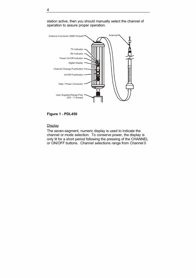
Figure 1 - PDL450
Display
The seven-segment, numeric display is used to indicate thechannel or mode selection. To conserve power, the display isonly lit for a short period following the pressing of the CHANNELor ON/OFF buttons. Channel selections range from Channel 0
Antenna Connector (NMO thread) Antenna
RX Indicator
TX Indicator
Power On/Off Indicator
Digital Display
Channel Change Pushbutton
On/Off Pushbutton
Data / Power Connector
User Supplied Range Pole(5/8 - 11 thread)

7/16/2019 M00667-03 pdl450 manual rev c-lw-js _9-30-05
http://slidepdf.com/reader/full/m00667-03-pdl450-manual-rev-c-lw-js-9-30-05 13/42
PDL450/HPB450 User's Guide 5
to Channel 15. Two-digit channel numbers are displayed byalternately flashing a "1" followed by the second digit.
Indicator LEDs
The power LED indicates the power status and also provides alow external voltage supply indicator. When lit, power is turnedon. The power LED will blink to indicate if the external voltagesupply is approaching the minimum value. If the power LEDdoes not respond to the ON/OFF button, then the level of the
external voltage supply should be inspected.
The RX LED indicates that the PDL450 is receiving an RF carrier signal from another base or from another source of interference.During normal operation, the RX LED will flash at a once-per-second rate indicating the transmissions from the base. If theRX LED is on continuously, then a source of interference may be
impacting the ability of the PDL450 to receive data. Tryrepositioning the antenna, or you may need to change to another channel at both the base and repeater to reduce or eliminate theinterference.
The TX LED indicates that the PDL450 is broadcasting. In mostGPS RTK applications, the TX LED will flash approximately one
time per second.
Enclosure
The PDL450 enclosure is a tough, impact-resistant, yellowpolycarbonate with machined aluminum end caps. Blackbumpers with integrated gaskets provide the first level of shockprotection for the internal components. An additional isolation

7/16/2019 M00667-03 pdl450 manual rev c-lw-js _9-30-05
http://slidepdf.com/reader/full/m00667-03-pdl450-manual-rev-c-lw-js-9-30-05 14/42
6
system inside the enclosure reduces vibration impact to thesensitive radio receiver board.
Antenna Mount
The integrated antenna mount provides an industry standardNMO style RF connector that is compatible with a wide range of mobile whip antennas.
Range Pole Mount
The bottom end cap is female threaded with 5/8 -11 UNC that iscompatible with common range poles. The unit is easilymounted in the place of a stand-alone antenna and eliminatesthe need for an antenna cable.
PDL450 Setup
Antenna and Antenna MountScrew the Antenna on the antenna mount of the PDL450. Werecommend inspecting the antenna center pushpin contact tomake sure that it makes good contact with the antenna mount. Agood antenna connection is critical to system performance.
Range Pole or Tripod Side Bracket Mount
Before connecting any cables, screw the PDL450 onto the rangepole (for tripod-top use) or tripod side mount bracket.

7/16/2019 M00667-03 pdl450 manual rev c-lw-js _9-30-05
http://slidepdf.com/reader/full/m00667-03-pdl450-manual-rev-c-lw-js-9-30-05 15/42
PDL450/HPB450 User's Guide 7
Battery Cable
GPS Data / Power Cable
Tripod TopMount
Side BracketMount
Figure 2 - PDL450 Setup

7/16/2019 M00667-03 pdl450 manual rev c-lw-js _9-30-05
http://slidepdf.com/reader/full/m00667-03-pdl450-manual-rev-c-lw-js-9-30-05 16/42
8
Connecting the PDL450
The PDL450 is connected to the RTK receiver using a GPS
interface cable (See Figure 3). Contact your Trimblerepresentative for the best cable selection to meet your surveying needs.
Figure 3 - PDL450 GPS Cable
After connecting the cable the radio will automatically turn itself on. Use the CHANNEL button to select the channel of operation,or select "r" for the AutoRover function or select "b" for the AutoBase function. Refer to the “How to Use AutoRover” and“How to Use AutoBase” sections of this manual for detailed
instructions concerning these features.
Battery CareBase station kit shipments include a 12 AHr deep-discharge gellead acid battery. This battery provides all day operation withample power for both the PDL450 and the GPS RTK referencestation. For a user supplied battery, select a deep discharge
battery that has a capacity of 12 AHr or greater. Batteries

7/16/2019 M00667-03 pdl450 manual rev c-lw-js _9-30-05
http://slidepdf.com/reader/full/m00667-03-pdl450-manual-rev-c-lw-js-9-30-05 17/42
PDL450/HPB450 User's Guide 9
designed for automotive use will be damaged by the repetitivedischarge/charge cycles and should be avoided.
ChargingThe supplied charger provides two-stage charging and should beconnected to the battery following every full day of operation toassure good battery life and performance. The first stage quicklycharges the battery to capacity and the second stage tricklecharges the battery to maintain a full charge.
If the battery is maintained in storage for an extended length of time, it is important to periodically charge the battery asextended time in a discharged state may damage the battery.
SETTING UP THE HPB450
Overview of the HPB450 Radio ModemFront Panel
Figure 4 - HPB450 Front Panel

7/16/2019 M00667-03 pdl450 manual rev c-lw-js _9-30-05
http://slidepdf.com/reader/full/m00667-03-pdl450-manual-rev-c-lw-js-9-30-05 18/42
10
Buttons
Note: The HPB450 is equipped with an “Auto Power On” feature,
which automatically turns on the HPB450 immediately uponbeing connected to a power source. The unit can also bemanually turned on or off as is described in the following paragraph.
The ON/OFF button is used to turn the HPB450 station on andoff. Turn the unit on by pressing the ON/OFF button and holding
it until the channel display indicator is lit. Turn off the HPB450 bypressing the ON/OFF button until the display goes blank. Thereis a one-second turn-off delay in the power button to preventinadvertent turn off.
The CHANNEL button is used to display and change thechannel. Press the CHANNEL button momentarily to display the
selected channel. To change the channel, press the CHANNELbutton once to light the display, and then again to change thechannel.
Use the CHANNEL button to select the “ b” setting. With “b”selected, the HPB450 will be placed in AutoBase mode. Thismode selects the channel for transmission automatically.
Display
The seven-segment numeric display is used to indicate thechannel or mode selection. To conserve power, the display isonly lit for a short time following the pressing of the CHANNEL or ON/OFF buttons. Channel selections range from Channel 0 to
/ G

7/16/2019 M00667-03 pdl450 manual rev c-lw-js _9-30-05
http://slidepdf.com/reader/full/m00667-03-pdl450-manual-rev-c-lw-js-9-30-05 19/42
PDL450/HPB450 User's Guide 11
Channel 15. Two digit channel numbers are displayed byalternately flashing a 1 followed by the second digit.
The seven-segment display also has a decimal point to the lower right of the number. The decimal point is lit to indicate that thechannel selection was done automatically with AutoRover or AutoBase.
Indicator LEDs
The power LED has two purposes – first, to indicate that the unitis powered, and second, to indicate the level of charge for thepower supply. The power LED will blink to indicate that th e basestation battery is at or below 10 Volts and may require charging.
The amplifier power LED indicates the RF power output levelselected. When lit, the amplifier power LED indicates that the
RF output power is set to high. When blank, the amplifier power LED indicates that the RF output power is set to low.
The TX LED indicates that the HPB450 is actively transmitting.In most RTK applications, the base station TX LED will blinkonce per second.
The RX LED indicates that the HPB450 is receiving an RFcarrier signal. If the RX LED is lit for extended periods of time, or continuously, then another radio station is operating on the samefrequency. This competing RF source may interfere with theGPS RTK system, and may require that you change channels for better performance.
12

7/16/2019 M00667-03 pdl450 manual rev c-lw-js _9-30-05
http://slidepdf.com/reader/full/m00667-03-pdl450-manual-rev-c-lw-js-9-30-05 20/42
12
Rear Panel
Data Connector
A five-pin circular LEMO style receptacle accepts bothprogramming and GPS model specific cables. The suppliedcables are labeled “RADIO” on the end that plugs into the base. Align the red dot on the plug with the red dot on the receptacleand push until a clicking sound is heard.
To remove the cable, grasp the cable over-mold, and retract the
locking mechanism by pulling the knurled barrel of the plugtoward your palm.
Figure 5 - HPB450 Rear Panel
Amp Power Selector Switch
Antenna Connector
Data / Power Connector
HOTSURFACE
CAUTION
PDL450/HPB450 User's Guide 13

7/16/2019 M00667-03 pdl450 manual rev c-lw-js _9-30-05
http://slidepdf.com/reader/full/m00667-03-pdl450-manual-rev-c-lw-js-9-30-05 21/42
PDL450/HPB450 User s Guide 13
RF Connector
A BNC jack accepts the BNC male plug coming from the
antenna mount.
Enclosure
The HPB450 enclosure is rugged extruded aluminum withintegrated heat sink fins. The enclosure is painted with aweather resistant powder coat yellow paint. Black bumpers areintegrated with front and rear gaskets to provide shock protection
and watertight operation. The enclosure is not designed towithstand submersion and must not be allowed to sit in standingwater.
Warning: The HPB450 enclosure and heat sink maybecome very hot during operation. This is normaldepending on the ambient temperature, RF power
selection and transmission duty cycle. Turn off the unitand allow it to cool prior to handling.
HPB450 System Setup
Antenna and Antenna Mount
Begin your HPB450 station setup by screwing the antenna
mount to the top of the tripod antenna mast. You may want toleave the mount permanently attached to the mast and avoid thisstep in the future.
Next, screw the antenna on the antenna mount. We recommendinspecting the antenna center pushpin contact to ensure that itmakes good contact with the antenna mount. A good antenna
connection is critical to system performance.
14

7/16/2019 M00667-03 pdl450 manual rev c-lw-js _9-30-05
http://slidepdf.com/reader/full/m00667-03-pdl450-manual-rev-c-lw-js-9-30-05 22/42
14
Tripod Antenna Mast
With the antenna mount and antenna connected, extend the legs
of the tripod antenna mast and set up the tripod on level ground.Spread the tripod legs sufficiently to provide a stable base.
Ant enna
Antenn a Mount
Tripod Mast
Antenna Cable
To GPS Unit
Data / Power Cable
Battery Cable
To Battery
Figure 6 - HPB450 System Setup
PDL450/HPB450 User's Guide 15

7/16/2019 M00667-03 pdl450 manual rev c-lw-js _9-30-05
http://slidepdf.com/reader/full/m00667-03-pdl450-manual-rev-c-lw-js-9-30-05 23/42
PDL450/HPB450 User s Guide 15
Caution: Do not extend the antenna mast in conditionsof high wind or in situations where the uneven terrain or
other soil conditions provide an unstable base. Keepthe area surrounding the tripod antenna mast clear andexercise caution to prevent injury or damage toproperty should the tripod antenna mast fall.
Connecting the HPB450
The HPB450 has a built-in, tripod-mounting bracket that allows
easy mounting to the tripod. Locate the mounting flange at thetop portion of one of the tripod legs, and hook the HPB450 inplace.
Connect the antenna, GPS data cable and battery power cableas indicated in Figure 6. You are now ready to turn-on thesystem.
Configuring the GPS Reference Station
Refer to GPS receiver model specific manual for specificinstructions on configuring your GPS reference station for optimal performance with the HPB450.
Battery Care
Base station kit shipments to North America include a 33 AHr deep-discharge gel lead acid battery. This battery provides all-day operation with ample power for both the HPB450 and theGPS RTK reference station.
16

7/16/2019 M00667-03 pdl450 manual rev c-lw-js _9-30-05
http://slidepdf.com/reader/full/m00667-03-pdl450-manual-rev-c-lw-js-9-30-05 24/42
16
International ShipmentsFor shipments outside of North America, we include a battery
bag, power cables with fuse, and hardware for a user-suppliedbattery. Select a deep-discharge battery of the type designed for golf cart or wheel chair operation, and that has a capacity of 33 AHr or greater. Batteries designed for automotive use will bedamaged by the repetitive discharge/charge cycles and shouldbe avoided.
ChargingThe supplied charger provides two-stage charging and should beconnected to the battery following every full day of operation toassure good battery life and performance. The first stage quicklycharges the battery to capacity and the second stage tricklecharges the battery to maintain a full charge.
If the battery is maintained in storage for an extended length of time, it is important to periodically charge the battery asextended time in a discharged state may damage the battery.
Default Settings
The PDL450 and HPB450 are configured at the factory withsettings that have been determined to provide excellent system
performance. Use the PDLCONF software provided with theproduct to view and change configuration settings.
Note: Please refer to the PDLCONF help menu systemfor detailed information concerning the settings.
PDL450/HPB450 User's Guide 17
7/16/2019 M00667-03 pdl450 manual rev c-lw-js _9-30-05
http://slidepdf.com/reader/full/m00667-03-pdl450-manual-rev-c-lw-js-9-30-05 25/42
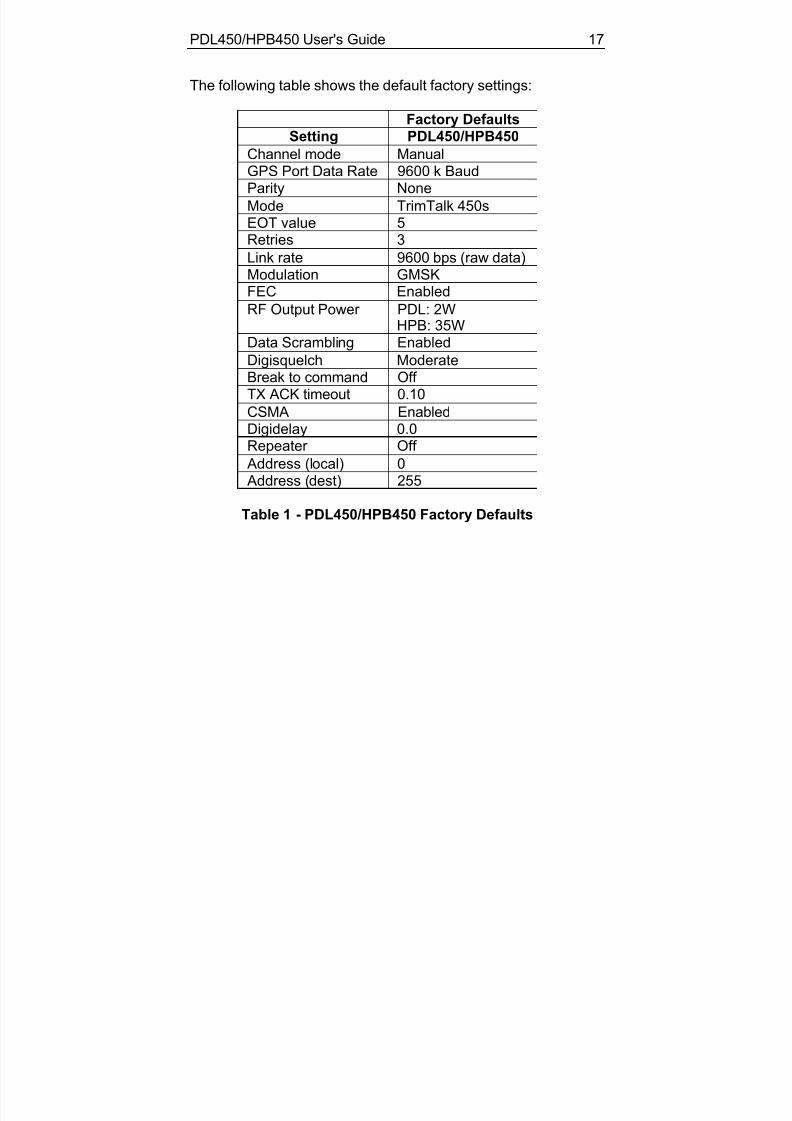
The following table shows the default factory settings:
Factory DefaultsSetting PDL450/HPB450
Channel mode ManualGPS Port Data Rate 9600 k BaudParity None
Mode TrimTalk 450sEOT value 5
Retries 3Link rate 9600 bps (raw data)Modulation GMSKFEC Enabled
RF Output Power PDL: 2WHPB: 35W
Data Scrambling Enabled
Digisquelch ModerateBreak to command Off TX ACK timeout 0.10
CSMA EnabledDigidelay 0.0Repeater Off
Address (local) 0 Address (dest) 255
Table 1 - PDL450/HPB450 Factory Defaults
18

7/16/2019 M00667-03 pdl450 manual rev c-lw-js _9-30-05
http://slidepdf.com/reader/full/m00667-03-pdl450-manual-rev-c-lw-js-9-30-05 26/42
TIPS AND TECHNIQUES FOR BEST PERFORMANCE
Antenna Antenna placement is critical for good performance. Range andcoverage is directly proportional to the height of the transmittingand receiving antennas in addition to antenna gain. Wherepossible, select a reference station location that takes advantageof terrain to get the transmitting antenna as high as possible.
Always use the telescoping antenna mast, and raise the antennaas high as is practical and safe, given terrain and windconditions.
Power Supp l ies
Maintain batteries in a fully charged state. We recommendroutinely connecting the PDL450 and HPB450 to its charger on anightly basis. This will assure optimal performance and longbattery life.
How to Use AutoRover™
AutoRover is a feature that allows the radio to automaticallysynchronize to a base. Enable this feature by pressing the
CHANNEL button until an "r
" is displayed. After selecting "r
",you will note that the display will flash each programmed channelfor approximately 3 seconds, until a base station broadcast isencountered. The radio will continue to scan until a broadcast isfound.
The next time you turn on your unit; you will see an "r"
momentarily, after which the scan process will begin. To
PDL450/HPB450 User's Guide 19
7/16/2019 M00667-03 pdl450 manual rev c-lw-js _9-30-05
http://slidepdf.com/reader/full/m00667-03-pdl450-manual-rev-c-lw-js-9-30-05 27/42
manually select a channel for operation, press the CHANNELbutton until the desired channel is displayed.
With AutoRover the radio scans each programmed operatingfrequency, looking for a signal from the base. When a signal isfound, the radio selects that channel for operation.
Caution: Multiple base stations operating in a singlearea may lead to the repeater selecting the wrong
base. In such circumstances, we recommend manuallyselecting the channel.
How to Use AutoB ase™
AutoBase is a feature that allows the base to automatically selecta channel based on a channel selection algorithm. Thesefeatures can be selectively turned off to allow you to manually
select the channel of operation on both the base and repeater.
To enable AutoBase, press the CHANNEL button on the baseuntil a "b" is displayed. After selecting "b", you will note that thedisplay will flash each programmed channel for approximately 1minute, during which time the channel is analyzed for background noise and co-channel interference.
After cycling through all channels, the base will select thechannel that appears to provide the clearest channel access.Following channel selection, the data received from the GPS willautomatically begin transmitting.
20

7/16/2019 M00667-03 pdl450 manual rev c-lw-js _9-30-05
http://slidepdf.com/reader/full/m00667-03-pdl450-manual-rev-c-lw-js-9-30-05 28/42
Warning: Depending on the number of channelsprogrammed, channel selection can take from 1 to 16
minutes. We recommend that you set up and turn onyour base station as soon as possible during systemsetup to prevent delays.
Equipm ent Care
Routine equipment care will prolong the life and reliability of your PDL450 and HPB450. Radio communication equipment is
susceptible to damage from shock or environmental extremes.Never operate the PDL450 or HPB450 out of the operatingspecifications contained in Appendix C.
Error Codes
The PDL450 and HPB450 perform a variety of power-up andrun-time tests to assure optimal operation. Tests include
environmental as well as electrical measurements designed toavoid damage to the unit while maintaining adequate operation.In the event of an error condition, a 3-digit error code is flashedon the display. Error codes begin with an "E" followed by twonumeric digits indicating the failure mode. Table 2 (p. 21) liststhe possible error conditions for the PDL450 and Table 3 (p. 22)lists the possible error conditions for the HPB450.
PDL450/HPB450 User's Guide 21

7/16/2019 M00667-03 pdl450 manual rev c-lw-js _9-30-05
http://slidepdf.com/reader/full/m00667-03-pdl450-manual-rev-c-lw-js-9-30-05 29/42
Code Description
E01 External voltage too highE02 External voltage too lowE03 External voltage too low for transmission
E08 Unit temperature exceeds safe limit for 2 W operationE10 Current consumption too high for 2 Watt operationE11 Checksum error
E12 RAM error
E13 EEPROM error E14 FLASH error
E15 TX Synth Lock Error E16 Synthesizer not lockedE99 Unknown error
Table 2 - PDL450 Error Codes
What to do
E01-E03 Check battery or power supply voltage level, checkpower cables, recharge or replace battery, check charger.E08 and E10 Check antenna and antenna cables, use 19200 linkrate to reduce duty cycle, select low RF power.
E11-E16, E99 Contact customer service.
Cycle power to clear error codes. If codes persist, contactfactory.
22

7/16/2019 M00667-03 pdl450 manual rev c-lw-js _9-30-05
http://slidepdf.com/reader/full/m00667-03-pdl450-manual-rev-c-lw-js-9-30-05 30/42
Code Description
E01 External voltage too high
E02 External voltage too lowE03 External voltage too low for transmissionE07 Unit temperature exceeds safe limit for 35 W operation
E08 Unit temperature exceeds safe limit for 2 W operationE09 Current consumption too high for 35 Watt operationE10 Current consumption too high for 2 Watt operation
E11 Checksum error
E12 RAM error E13 EEPROM error
E14 FLASH error E15 TX Synth Lock Error E16 Synthesizer not locked
E99 Unknown error
Table 3 – HPB450 Error Codes
What to do
E01-E03 Check battery or power supply voltage level, checkpower cables, recharge or replace battery, check charger.E08-E10 Check antenna and antenna cables, use 19200 link
rate to reduce duty cycle, select low RF power.E11-E16, E99 Contact customer service.
Cycle power to clear error codes. If codes persist, contactfactory.
PDL450/HPB450 User's Guide 23

7/16/2019 M00667-03 pdl450 manual rev c-lw-js _9-30-05
http://slidepdf.com/reader/full/m00667-03-pdl450-manual-rev-c-lw-js-9-30-05 31/42
FCC RULES AND REGULATIONS
Licensing Requirements It is the responsibility of the base station owner to comply withapplicable rules and regulations concerning the operation of aradio transmitter. In the United States, the FCC regulates thelicensing of this equipment.
Application for a license is made by submitting FCC form 600
along with evidence of frequency coordination (if required) andapplicable fees. Similar licensing requirements exist worldwide.Penalties for broadcasting without a license can be severe, andmay include the confiscation of your radio and GPS equipment.
For more information, contact our customer service department.
Warning: Always obey local licensing requirementsand restrictions.
Equipment Comp liances
The PDL450 and HPB450 have been tested and found to complywith Parts 15 and 90 of Title 47 of the Code of FederalRegulations. These products have also been tested and foundcompliant for type certification and approval in many other countries worldwide.
For more information concerning our worldwide compliances,contact our customer service department.
24

7/16/2019 M00667-03 pdl450 manual rev c-lw-js _9-30-05
http://slidepdf.com/reader/full/m00667-03-pdl450-manual-rev-c-lw-js-9-30-05 32/42
Being Part of the RF Communi ty
Operation of a licensed radio product makes you a member of
the RF community. Be aware that virtually all frequencieslicensed are provided on a shared basis with other users. Eachfrequency used in RTK GPS activities has certa in restrictionsand limitations. For complete information, refer to Part 90, Title47, of the Code of Federal Regulations.
Most frequencies sharing data transmissions and voice
transmissions give priority to voice users. Be mindful of thepersistent nature of a GPS RTK data transmission and alwayslimit your RF transmission output power when performing close-in survey situations to avoid interference with co-channel users.We recommend using the low RF power setting for constructionsite and other line-of-site surveys with baselines less than 2miles (depending on terrain).
Warning: If you are in conflict with a co-channel user,select another frequency to avoid formal FCC actions.In most cases you are required to vacate a frequencyupon complaint by a shared channel voice user.
Most survey operations are itinerant in that the system is moved
on a frequent basis. For fixed system installations, you shouldnot use frequencies set aside for itinerant operations, but shouldcoordinate a frequency based on the fixed area operation.
Regulations differ from country to country, so please be aware of the local regulations prior to using the PDL450 and HPB450equipment.
PDL450/HPB450 User's Guide 25

7/16/2019 M00667-03 pdl450 manual rev c-lw-js _9-30-05
http://slidepdf.com/reader/full/m00667-03-pdl450-manual-rev-c-lw-js-9-30-05 33/42
Au tomatic Station Identi f ication
For operation in the United States, the FCC requires that radio
transmitters used for GPS RTK applications periodicallybroadcast a station identifier. The station identifier is the callsign assigned to you on the station license.
The PDL450 and HPB450 support the broadcast of stationidentification in a manner that meets the requirements of theFCC. Upon receipt of equipment, program your FCC call sign
into the configuration of your base using PDLCONF software.This is only required for transmitters.
Warning: Failure to transmit your station identi ficationis in violation of FCC regulations. Use PDLCONFsoftware to enter your FCC call sign.
Carrier Sense Mu ltiple Access (CSMA) CSMA is a technology implemented in the base to meet FCCtransmitter requirements. CSMA holds off the radio transmissionif a co-channel user is currently using the frequency. Onoccasion, you may note that the radio broadcasts stop for shortperiods of time. Most often, this is a case of co-channelinterference and the base is holding off broadcasts due to the
FCC mandated CSMA.
GPS RTK equipment is designed to function with intermittentgaps in the data. Heavy co-channel use may limit the ability of the base to transmit the required information. In areas of heavyco-channel usage, try changing channels to a less usedfrequency.
26

7/16/2019 M00667-03 pdl450 manual rev c-lw-js _9-30-05
http://slidepdf.com/reader/full/m00667-03-pdl450-manual-rev-c-lw-js-9-30-05 34/42
This page intentionally left blank.
PDL450/HPB450 User's Guide 27

7/16/2019 M00667-03 pdl450 manual rev c-lw-js _9-30-05
http://slidepdf.com/reader/full/m00667-03-pdl450-manual-rev-c-lw-js-9-30-05 35/42
SERVICE AND SUPPORT
Contacting Trimb le Navigation Ltd .Phone: U.S.A. 1-800-767-4822
Europe +49 6142 2100 555
Web: www.trimble.com
Mail: 935 Stewart DriveSunnyvale, CA 94085
28

7/16/2019 M00667-03 pdl450 manual rev c-lw-js _9-30-05
http://slidepdf.com/reader/full/m00667-03-pdl450-manual-rev-c-lw-js-9-30-05 36/42
APPENDIX A - SAFETY INFORMATION
Expos ure to Radio Frequency Energy
Radio modem products are designed to comply with thefollowing national and international standards and guidelinesregarding exposure of human beings to radio frequencyelectromagnetic energy:
• FCC Report and Order FCC 96-326 (August, 1996)• American National Standards Institute (C95.3-1992)
• National Council on Radiation Protection and Measurement(NCRP - 1986)
• International Commission on Non-ionizing RadiationProtection (ICNRP - 1986)
• European Committee for Electrotechnical Standardization(CENELEC)
To assure optimal radio performance and to ensure thatexposure to RF energy is within the guidelines in the abovestandards, the following operating procedures should beobserved:
• DO NOT operate a transceiver when someone is within thedistance noted below of the antenna:
120 cm (approx. 4 feet) for HPB450 35 Watt30 cm (approx. 12 inches) for PDL450 2 Watt15 cm (approx. 6 inches) for PDL450 1/2 Watt
PDL450/HPB450 User's Guide 29

7/16/2019 M00667-03 pdl450 manual rev c-lw-js _9-30-05
http://slidepdf.com/reader/full/m00667-03-pdl450-manual-rev-c-lw-js-9-30-05 37/42
• DO NOT operate the transceiver unless all RF connectorsare secure and any open connectors are properly
terminated.• Avoid contact with the antenna while operating thetransceiver.
• DO NOT operate the transceiver with a damaged antenna. If a damaged antenna comes in contact with the skin, a minor burn may result.
• DO NOT operate the equipment near electrical blasting caps
or in an explosive atmosphere.
Radio modem products are designed to comply with the followingnational and international standards and guidelines regardingexposure of human beings to radio frequency electromagneticenergy, in addition to protection against harmful interference of neighboring electrical equipment:
• FCC CFR47 Part 15
• FCC CFR47 Part 90
• Industry Canada RSS 119• ETSI EN 300 113
• ETSI EN 300 220
• ETSI EN 300 489
• ACA AS/NZS 4295• iDA Spec 111• OFTA STD-1E
• SRRC CMII
Contact your sales representative for model specific countryapproval.
PDL450/HPB450 User's Guide30

7/16/2019 M00667-03 pdl450 manual rev c-lw-js _9-30-05
http://slidepdf.com/reader/full/m00667-03-pdl450-manual-rev-c-lw-js-9-30-05 38/42
APPENDIX B - PIN-OUTS AND CONNECTORS
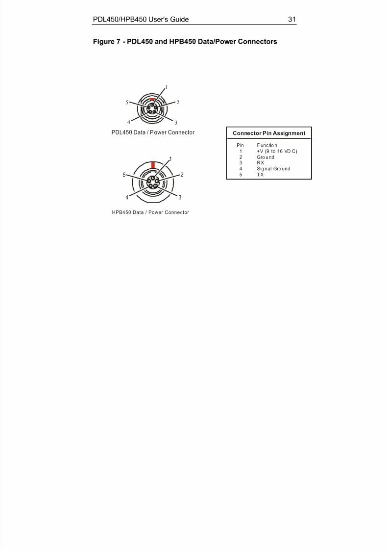
PDL450 The PDL450 data receptacle is a LEMO PN HMG.0B.305.CLN.For a mating plug, we recommend LEMO PNFHG.0B.305.CLAD.52Z. Refer to Table 4 (below) and Figure 7(p. 32) for connector pin assignments.
HPB450
The base data receptacle is a LEMO PN HGG.1B.305.CLLP.For a mating plug, we recommend LEMO PNFGG.1B.305.CLAD.72Z. Refer to Table 4 and Figure 7(p. 33) for pin-outs and orientation.
Pin # Description Cable Wire Color
1 Power Red
2 Ground Black3 RS-232 RX Data Yellow4 RS-232 Signal Ground White5 RS-232 TX Data Green
Table 4 - PDL450/HPB450 Pin Assignments
Antenna
The PDL450 antenna connector is an industry standard NMO.The impedence is 50 Ω.
Connector Manufacturer ContactsContact LEMO USA by calling 1-707-578-8811Contact Amphenol by calling 1-203-743-9272
PDL450/HPB450 User's Guide 31
7/16/2019 M00667-03 pdl450 manual rev c-lw-js _9-30-05
http://slidepdf.com/reader/full/m00667-03-pdl450-manual-rev-c-lw-js-9-30-05 39/42
Figure 7 - PDL450 and HPB450 Data/Power Connectors
PDL450 Data / P ower Connector
1
2
3
5
Connector Pin Assignment
Pin F unc tio n1 +V (9 to 16 VD C)2 Gro u nd3 R X4 Sig nal Gro und5 T X
HPB450 Data / Power Connector
1
2
34
5
PDL450/HPB450 User's Guide32

7/16/2019 M00667-03 pdl450 manual rev c-lw-js _9-30-05
http://slidepdf.com/reader/full/m00667-03-pdl450-manual-rev-c-lw-js-9-30-05 40/42
APPENDIX C - TECHNICAL SPECIFICATIONS
General Serial Port Interface
RS-232 compatible. 1200 to 38400 baud operation with 1 start,8 data, optional parity, and one stop bit.
Power Supply
The PDL450 quiescent/receive power consumption is 0.9W. ThePDL450 when transmitting consumes 5W/11W depending on RFpower. (PDL450 power consumption measured at 12.5 VDC.)The HPB450 quiescent/receive power consumption is 1.9W.The HPB450 in the low/high RF power setting consumes13W/125W during transmission.
Radio
Frequency Ranges
Contact factory for available frequency ranges. Synthesizedfrequency control with approximately 1600 channel capability.Channel spacing 25/12.5 kHz. 2.5 ppm frequency reference.
Transmitter (PDL450)
Carrier power for the PDL450 is factory programmable for 0.5Wor 2W. Carrier power for the HPB450 is selectable between2 Watts and 35 Watts. Output impedance 50-ohms. Modulationdistortion is less than 5%. Transmitter attack time < 18 ms.Spurious and harmonic FM -55 dBc. FM hum and noise -40dBm.
PDL450/HPB450 User's Guide 33

7/16/2019 M00667-03 pdl450 manual rev c-lw-js _9-30-05
http://slidepdf.com/reader/full/m00667-03-pdl450-manual-rev-c-lw-js-9-30-05 41/42
Receiver
Sensitivity -116 dBm or better (12dB SINAD). Selectivity for the
PDL450 is -70dB (9600, GMSK, 25 KHz), and -60 dB (19,200,4LFSK, 25 KHz). Selectivity for the HPB450 is -60 dB. FM humand noise -40 dB. Conducted spurious -65 dB. Carrier detectattack time 2 ms.
Modem
Transmission Rate
19,200 or 9,600 bits per second (Four-level FSK)9,600 or 4,800 bits per second (GMSK)
Transmission Protocols
Transparent, packet switched, auto-repeater, fast asynchronous,Trimtalk™
Forward Error Correction and Detection
With FEC enabled, data is encoded by a block code. The data isinterleaved in blocks of 20 words, giving burst error correctioncapabilities for up to 20 consecutive corrupted bits. 16-bit CRCsare generated and sent with every block of data providing 100%error detection for burst errors shorter than 16 bits, and99.9984% detection of all other burst errors.
Modulation
Gaussian Minimum Shift Keying (GMSK) with BT of 0.5 (4800,9600 bps link rate). Four-level FSK (9600, 19200 bps link rate).
34

7/16/2019 M00667-03 pdl450 manual rev c-lw-js _9-30-05
http://slidepdf.com/reader/full/m00667-03-pdl450-manual-rev-c-lw-js-9-30-05 42/42
Environmental
Size
PDL450 - 8.25" L x 2.40" D (21.0 cm L x 6.1 cm D)HPB450 - 6.23" W x 2.77" H x 6.58" L (15.8 cm W x 7.0 cm H x16.7 cm L)
Weight
PDL450 - 0.65 lbs. (0.30 Kg)HPB450 - 3.22 lbs. (1.46 Kg)
Shock and Vibration
Per ANSI/ASAE EP455
Protection
Per IEC 144/855420 I.P. 66 Dust-tight and watertight
Temperature Range
PDL450 Operating - 22° to 140° F (-30° to 60° C)PDL450 Storage - 67° to 185° F (-55° to 85° C)
HPB450 Operating - -22° to 140° F (-30° to 60° C)HPB450 Storage - -67° to 185° F (-55° to 85° C)