
M ROCKY-4786EVGR ENG V1-0 - ipcland.net · 3 Table of Contents CHAPTER 1 INTRODUCTION.....5 1.1...
65
1 ROCKY-4786EVGR User Manual Version 1.0 SOCKET 478 PENTIUM 4/4-M with Ethernet & USB 2.0 & SATA RAID APRIL 14, 2005 © Copyright 2004 by ICP Electronic Inc. All Rights Reserved.
-
Upload
hoangthien -
Category
Documents
-
view
221 -
download
0
Transcript of M ROCKY-4786EVGR ENG V1-0 - ipcland.net · 3 Table of Contents CHAPTER 1 INTRODUCTION.....5 1.1...

1
ROCKY-4786EVGR User Manual
Version 1.0
SOCKET 478 PENTIUM 4/4-M with Ethernet & USB 2.0 & SATA RAID
APRIL 14, 2005
© Copyright 2004 by ICP Electronic Inc. All Rights Reserved.

2
Copyright Notice The information in this document is subject to change without prior notice in order to improve reliability, design and function and does not represent a commitment on the part of the manufacturer. In no event will the manufacturer be liable for direct, indirect, special, incidental, or consequential damages arising out of the use or inability to use the product or documentation, even if advised of the possibility of such damages. This document contains proprietary information protected by copyright. All rights are reserved. No part of this manual may be reproduced by any mechanical, electronic, or other means in any form without prior written permission of the manufacturer.
Trademarks ROCKY-4786EVGR is registered trademarks of ICP Electronics Inc.; IBM PC is a registered trademark of International Business Machines Corporation. INTEL is a registered trademark of INTEL Corporation. AMI is registered trademarks of American Megatrends Inc.,Other product names mentioned herein are used for identification purposes only and may be trademarks and/or registered trademarks of their respective companies.
Support Any questions regarding the content of this manual or related issues can be e-mailed to us directly at: [email protected]
3
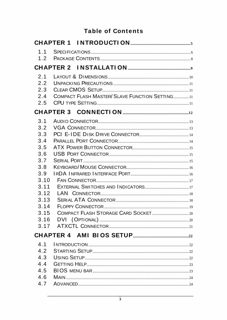
Table of Contents
CHAPTER 1 INTRODUCTION......................................................................5
1.1 SPECIFICATIONS .................................................................................................................... 6 1.2 PACKAGE CONTENTS ......................................................................................................... 8
CHAPTER 2 INSTALLATION.........................................................................9
2.1 LAYOUT & DIMENSIONS .............................................................................................. 10 2.2 UNPACKING PRECAUTIONS ........................................................................................ 11 2.3 CLEAR CMOS SETUP..................................................................................................... 11 2.4 COMPACT FLASH MASTER/SLAVE FUNCTION SETTING.................. 11 2.5 CPU TYPE SETTING........................................................................................................... 11
CHAPTER 3 CONNECTION.............................................................................12
3.1 AUDIO CONNECTOR.......................................................................................................... 13 3.2 VGA CONNECTOR............................................................................................................. 13 3.3 PCI E-IDE DISK DRIVE CONNECTOR.......................................................... 14 3.4 PARALLEL PORT CONNECTOR................................................................................... 14 3.5 ATX POWER BUTTON CONNECTOR.................................................................. 15 3.6 USB PORT CONNECTOR ............................................................................................. 15 3.7 SERIAL PORT ........................................................................................................................... 15 3.8 KEYBOARD/MOUSE CONNECTOR......................................................................... 16 3.9 IRDA INFRARED INTERFACE PORT.................................................................... 16 3.10 FAN CONNECTOR............................................................................................................ 17 3.11 EXTERNAL SWITCHES AND INDICATORS................................................... 17 3.12 LAN CONNECTOR....................................................................................................... 18 3.13 SERIAL ATA CONNECTOR ..................................................................................... 18 3.14 FLOPPY CONNECTOR ................................................................................................... 19 3.15 COMPACT FLASH STORAGE CARD SOCKET........................................... 20 3.16 DVI (OPTIONAL) ........................................................................................................ 20 3.17 ATXCTL CONNECTOR ............................................................................................. 21
CHAPTER 4 AMI BIOS SETUP.................................................................22
4.1 INTRODUCTION ..................................................................................................................... 22 4.2 STARTING SETUP ................................................................................................................ 22 4.3 USING SETUP ......................................................................................................................... 22 4.4 GETTING HELP....................................................................................................................... 23 4.5 BIOS MENU BAR ................................................................................................................ 23 4.6 MAIN ............................................................................................................................................... 24 4.7 ADVANCED................................................................................................................................. 24
4
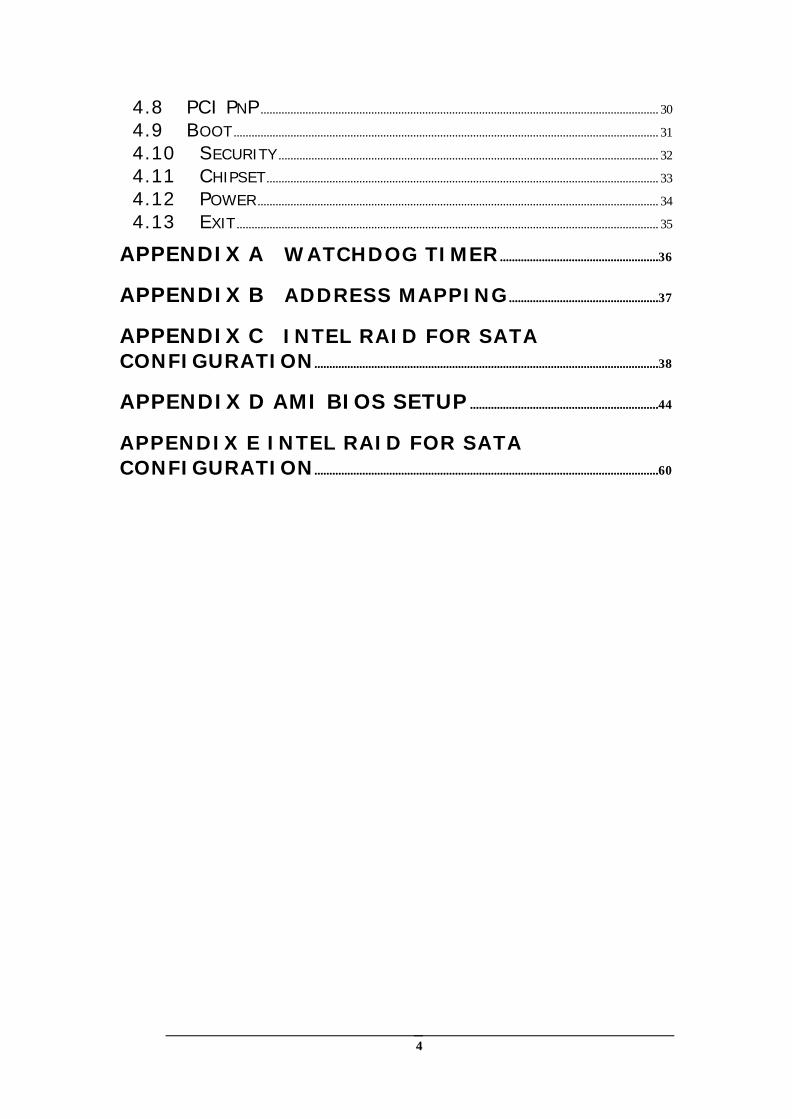
4.8 PCI PNP ..................................................................................................................................... 30 4.9 BOOT .............................................................................................................................................. 31 4.10 SECURITY ............................................................................................................................... 32 4.11 CHIPSET................................................................................................................................... 33 4.12 POWER...................................................................................................................................... 34 4.13 EXIT ............................................................................................................................................. 35
APPENDIX A WATCHDOG TIMER .....................................................36
APPENDIX B ADDRESS MAPPING ..................................................37
APPENDIX C INTEL RAID FOR SATA CONFIGURATION...................................................................................................................38
APPENDIX D AMI BIOS SETUP ...............................................................44
APPENDIX E INTEL RAID FOR SATA CONFIGURATION...................................................................................................................60

5
Chapter 1 Introduction
Thank you for choosing ROCKY-4786EVGR SOCKET 478 PENTIUM 4 Single Board Computer. The ROCKY-4786EVGR board is an PICMG form factor board, which comes fully equipped with high performance Processor and advanced high performance multi-mode I/O, designed for the system manufacturers, integrators, or VARs that want to provide all the performance, reliability, and quality at a reasonable price. In addition, ROCKY-4786EVGR built in a 3D AGP 4X controller (Intel 865GV), which provides up to 2048x1536x16-color clear resolution that shares 1/8/16MB system DDR-SDRAM. ROCKY-4786EVGR supports one or two 64-bit wide DDR400 data channels. Available bandwidth up to 3.2GB/s in single-channel mode and 6.4GB/s in dual-channel mode. The CSA interface connects the GMCH with a Gigabit Ethernet controller. ROCKY-4786EVGR’s built-in ICH5R has 10/100 Fast Ethernet LAN capability. It is fully integrated 10BASE-T/100BASE-TX LAN solution with high performance networking functions and low power features. The ICH5R has an integrated SATA host controller that supports independent DMA operation on two port and supports data transfer rate of up to 1.5Gb/s.The ICH5R Offers data striping for higher performance(RAID Level 0),and offers mirroring for Data security(RAID Level 1). For applications that needs high speed serial transmission, the ROCKY-4786EVGR provides USB2.0 for your convenience. The high speed USB2.0 host controller implements an ECHI interface that provides bandwidth up to 480Mb/s.
6
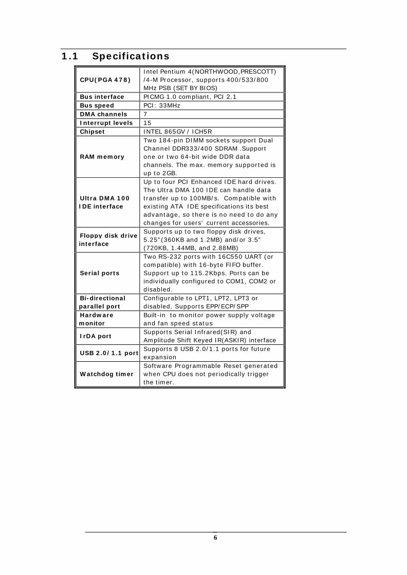
1.1 Specifications
CPU(PGA 478) Intel Pentium 4(NORTHWOOD,PRESCOTT) /4-M Processor, supports 400/533/800 MHz PSB (SET BY BIOS)
Bus interface PICMG 1.0 compliant, PCI 2.1 Bus speed PCI: 33MHz DMA channels 7 Interrupt levels 15 Chipset INTEL 865GV / ICH5R
RAM memory
Two 184-pin DIMM sockets support Dual Channel DDR333/400 SDRAM .Support one or two 64-bit wide DDR data channels. The max. memory supported is up to 2GB.
Ultra DMA 100 IDE interface
Up to four PCI Enhanced IDE hard drives. The Ultra DMA 100 IDE can handle data transfer up to 100MB/s. Compatible with existing ATA IDE specifications its best advantage, so there is no need to do any changes for users’ current accessories.
Floppy disk drive interface
Supports up to two floppy disk drives, 5.25”(360KB and 1.2MB) and/or 3.5” (720KB, 1.44MB, and 2.88MB)
Serial ports
Two RS-232 ports with 16C550 UART (or compatible) with 16-byte FIFO buffer. Support up to 115.2Kbps. Ports can be individually configured to COM1, COM2 or disabled.
Bi-directional parallel port
Configurable to LPT1, LPT2, LPT3 or disabled. Supports EPP/ECP/SPP
Hardware monitor
Built-in to monitor power supply voltage and fan speed status
IrDA port Supports Serial Infrared(SIR) and Amplitude Shift Keyed IR(ASKIR) interface
USB 2.0/1.1 port Supports 8 USB 2.0/1.1 ports for future expansion
Watchdog timer Software Programmable Reset generated when CPU does not periodically trigger the timer.
7
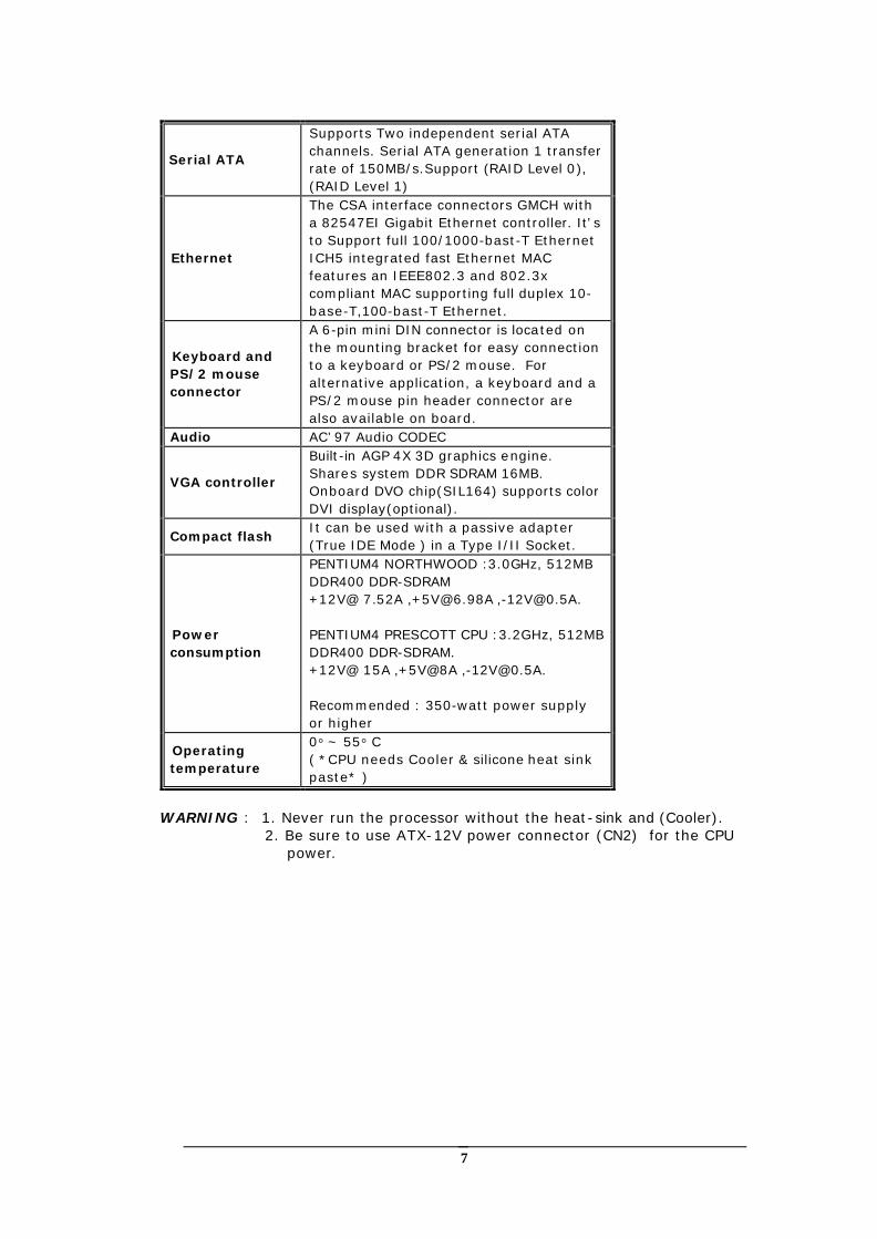
Serial ATA
Supports Two independent serial ATA channels. Serial ATA generation 1 transfer rate of 150MB/s.Support (RAID Level 0), (RAID Level 1)
Ethernet
The CSA interface connectors GMCH with a 82547EI Gigabit Ethernet controller. It’s to Support full 100/1000-bast-T Ethernet ICH5 integrated fast Ethernet MAC features an IEEE802.3 and 802.3x compliant MAC supporting full duplex 10-base-T,100-bast-T Ethernet.
Keyboard and PS/2 mouse connector
A 6-pin mini DIN connector is located on the mounting bracket for easy connection to a keyboard or PS/2 mouse. For alternative application, a keyboard and a PS/2 mouse pin header connector are also available on board.
Audio AC’97 Audio CODEC
VGA controller
Built-in AGP 4X 3D graphics engine. Shares system DDR SDRAM 16MB. Onboard DVO chip(SIL164) supports color DVI display(optional).
Compact flash It can be used with a passive adapter (True IDE Mode ) in a Type I/II Socket.
Power consumption
PENTIUM4 NORTHWOOD :3.0GHz, 512MB DDR400 DDR-SDRAM +12V@ 7.52A ,[email protected] ,[email protected]. PENTIUM4 PRESCOTT CPU :3.2GHz, 512MB DDR400 DDR-SDRAM. +12V@ 15A ,+5V@8A ,[email protected]. Recommended : 350-watt power supply or higher
Operating temperature
0° ~ 55° C ( *CPU needs Cooler & silicone heat sink paste* )
WARNING : 1. Never run the processor without the heat-sink and (Cooler).
2. Be sure to use ATX-12V power connector (CN2) for the CPU power.
8
1.2 Package Contents The ROCKY-4786EVGR package includes the following items:
l One ROCKY-4786EVGR Single Board Computer l One RS-232 & Printer Cables with bracket l One FDD cable. l One ATA IDE cable. l Two SATA IDE cables. l One SATA Power cord. l One ATX-12V cable. l One keyboard and mouse Y-Adapter cable. l One Driver CD l User manual If any of these items are missing or damaged, please contact the dealer from whom you purchased this product. Save the shipping materials and carton in case you want to ship or store the product in the future.

9
Chapter 2 Installation
This chapter describes how to install the ROCKY-4786EVGR. First a layout diagram of the ROCKY-4786EVGR is shown, followed by unpacking information that should be carefully followed. The jumpers and switch settings for the ROCKY-4786EVGR configuration, such as CPU type selection, system clock setting, and watchdog timer, are also listed.
(This space is intentionally left blank. Please refer to the next page.)
10
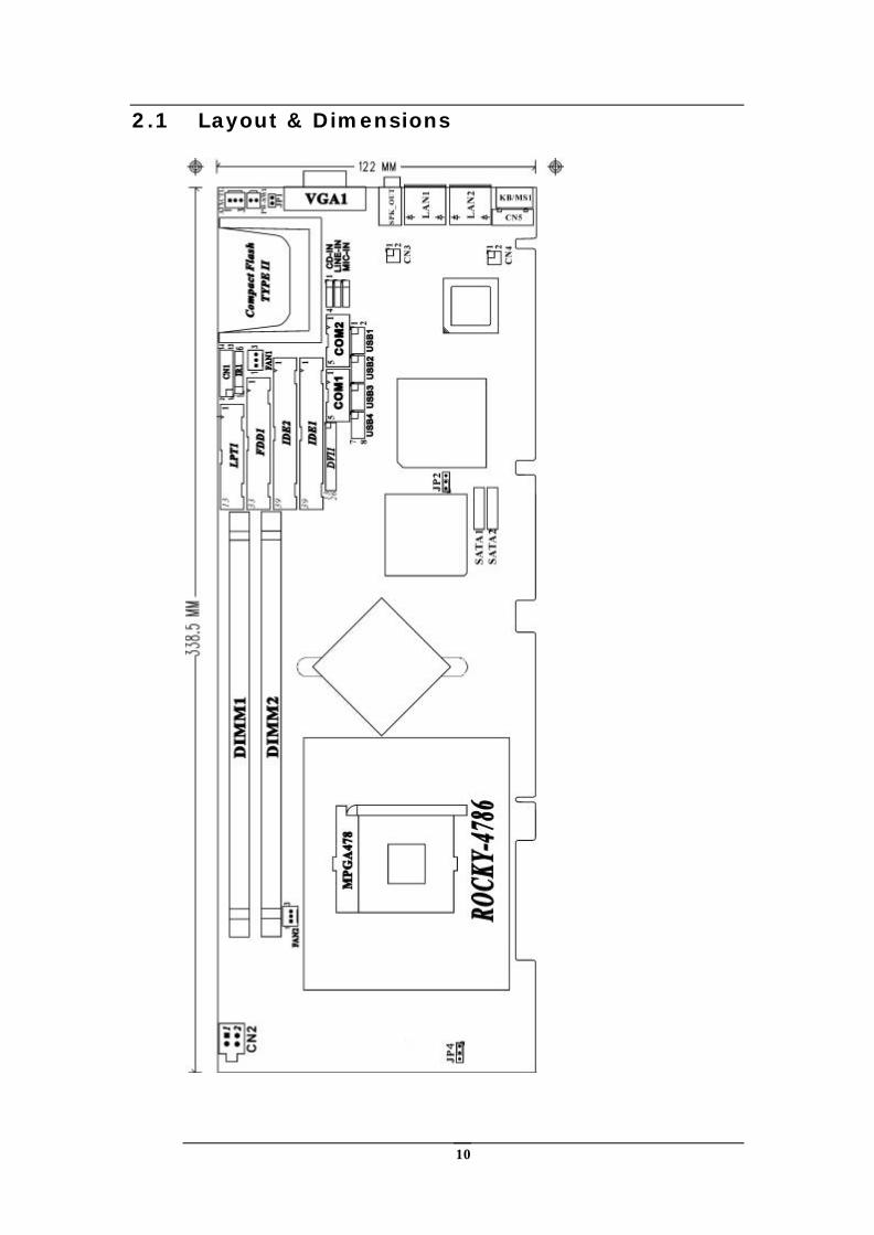
2.1 Layout & Dimensions
11
2.2 Unpacking Precautions Some components on ROCKY-4786EVGR are very sensitive to static electric charges and can be damaged by a sudden rush of power. To protect it from unintended damage, be sure to follow these precautions:
l Ground yourself to remove any static charge before touching your ROCKY-
4786EVGR. You can do it by using a grounded wrist strap at all times or by frequently touching any conducting materials that is connected to the ground.
l Handle your ROCKY-4786EVGR by its edges. Don’t touch IC chips, leads or
circuitry if not necessary. l Do not plug any connector or jumper while the power is on. Note: All shaded rows in tables of this manual are the
default settings for ROCKY-4786EVGR.
2.3 Clear CMOS Setup To clear the CMOS Setup (for example if you have forgotten the password, you should clear the CMOS and then re-set the password), you should close the JP2 (2-3) for about 3 seconds, then open it once more. This will set back to normal operation mode.
• JP2 : Clear CMOS Setup
JP2 DESCRIPTION 1-2 or open (default)*
Keep CMOS Setup (Normal Operation)
2-3 Clear CMOS Setup
2.4 Compact Flash Master/Slave Function Setting
• JP1 : Compact Flash Master/Slave Function Setting Short 1 - 2 pin , Compact Flash is Master
JP1 DESCRIPTION Short Master Open Slave
2.5 CPU type Setting ROCKY-4786EVGR board can use two different types of CPU. One is Pentium4 CPU model and the other is Pentium4-M CPU.
l 2.5-1: When using Pentium4 CPU, please short JP4 (1-2). CPU VID will now
automatically configure the power of CPU. (Default)
l 2.5-2: When using Pentium4-M CPU, please short JP4 (2-3). The power of CPU will be set to 1.3V at this time.
JP4 DESCRIPTION
Short (1-2) Pentium4 CPU Short (2-3) Pentium4-M CPU
12
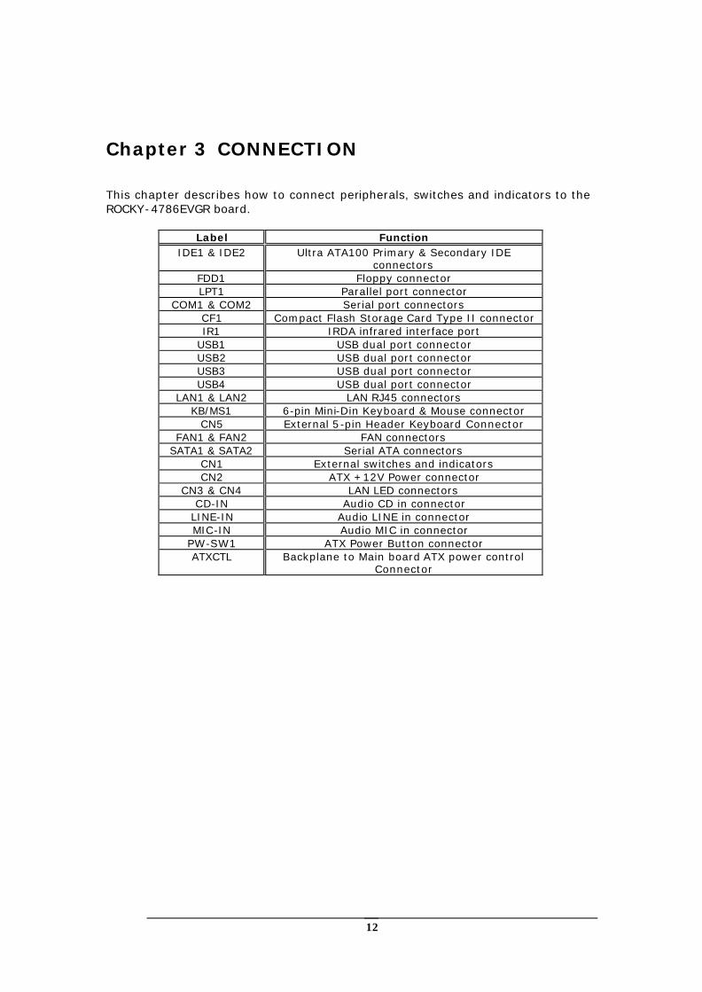
Chapter 3 CONNECTION
This chapter describes how to connect peripherals, switches and indicators to the ROCKY-4786EVGR board.
Label Function IDE1 & IDE2 Ultra ATA100 Primary & Secondary IDE
connectors FDD1 Floppy connector LPT1 Parallel port connector
COM1 & COM2 Serial port connectors CF1 Compact Flash Storage Card Type II connector IR1 IRDA infrared interface port
USB1 USB dual port connector USB2 USB dual port connector USB3 USB dual port connector USB4 USB dual port connector
LAN1 & LAN2 LAN RJ45 connectors KB/MS1 6-pin Mini-Din Keyboard & Mouse connector
CN5 External 5-pin Header Keyboard Connector FAN1 & FAN2 FAN connectors
SATA1 & SATA2 Serial ATA connectors CN1 External switches and indicators CN2 ATX +12V Power connector
CN3 & CN4 LAN LED connectors CD-IN Audio CD in connector
LINE-IN Audio LINE in connector MIC-IN Audio MIC in connector
PW-SW1 ATX Power Button connector ATXCTL Backplane to Main board ATX power control
Connector
13
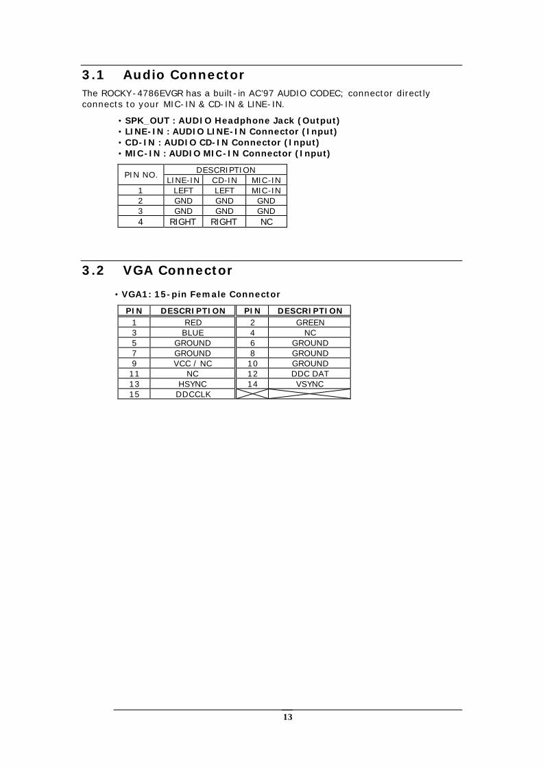
3.1 Audio Connector The ROCKY-4786EVGR has a built-in AC’97 AUDIO CODEC; connector directly connects to your MIC-IN & CD-IN & LINE-IN.
• SPK_OUT : AUDIO Headphone Jack (Output) • LINE-IN : AUDIO LINE-IN Connector (Input) • CD-IN : AUDIO CD-IN Connector (Input) • MIC-IN : AUDIO MIC-IN Connector (Input)
DESCRIPTION PIN NO. LINE-IN CD-IN MIC-IN
1 LEFT LEFT MIC-IN 2 GND GND GND 3 GND GND GND 4 RIGHT RIGHT NC
3.2 VGA Connector
• VGA1: 15-pin Female Connector
PIN DESCRIPTION PIN DESCRIPTION 1 RED 2 GREEN 3 BLUE 4 NC 5 GROUND 6 GROUND 7 GROUND 8 GROUND 9 VCC / NC 10 GROUND 11 NC 12 DDC DAT 13 HSYNC 14 VSYNC 15 DDCCLK
14
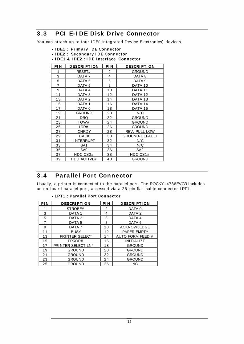
3.3 PCI E-IDE Disk Drive Connector You can attach up to four IDE( Integrated Device Electronics) devices.
• IDE1 : Primary IDE Connector • IDE2 : Secondary IDE Connector • IDE1 & IDE2 : IDE Interface Connector
PIN DESCRIPTION PIN DESCRIPTION 1 RESET# 2 GROUND 3 DATA 7 4 DATA 8 5 DATA 6 6 DATA 9 7 DATA 5 8 DATA 10 9 DATA 4 10 DATA 11 11 DATA 3 12 DATA 12 13 DATA 2 14 DATA 13 15 DATA 1 16 DATA 14 17 DATA 0 18 DATA 15 19 GROUND 20 N/C 21 DRQ 22 GROUND 23 IOW# 24 GROUND 25 IOR# 26 GROUND 27 CHRDY 28 REV. PULL LOW 29 DACK 30 GROUND-DEFAULT 31 INTERRUPT 32 N/C 33 SA1 34 N/C 35 SA0 36 SA2 37 HDC CS0# 38 HDC CS1# 39 HDD ACTIVE# 40 GROUND
3.4 Parallel Port Connector Usually, a printer is connected to the parallel port. The ROCKY-4786EVGR includes an on-board parallel port, accessed via a 26-pin flat-cable connector LPT1.
• LPT1 : Parallel Port Connector
PIN DESCRIPTION PIN DESCRIPTION 1 STROBE# 2 DATA 0 3 DATA 1 4 DATA 2 5 DATA 3 6 DATA 4 7 DATA 5 8 DATA 6 9 DATA 7 10 ACKNOWLEDGE 11 BUSY 12 PAPER EMPTY 13 PRINTER SELECT 14 AUTO FORM FEED # 15 ERROR# 16 INITIALIZE 17 PRINTER SELECT LN# 18 GROUND 19 GROUND 20 GROUND 21 GROUND 22 GROUND 23 GROUND 24 GROUND 25 GROUND 26 NC
15
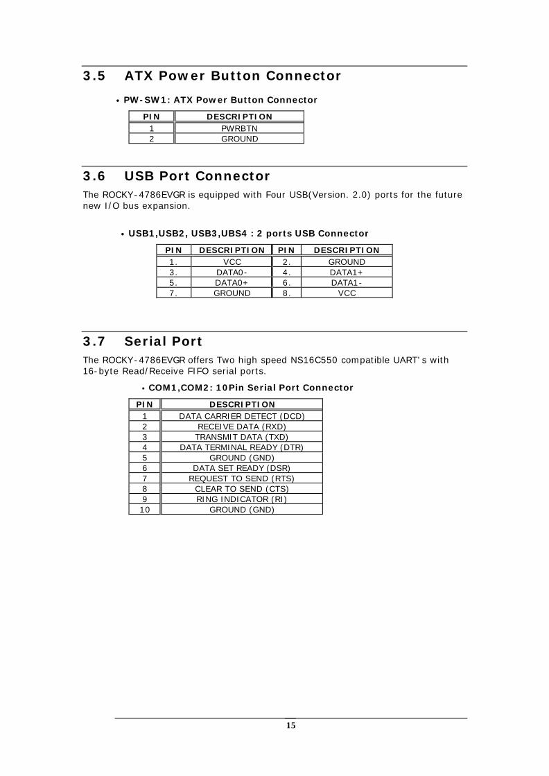
3.5 ATX Power Button Connector
• PW-SW1: ATX Power Button Connector
PIN DESCRIPTION 1 PWRBTN 2 GROUND
3.6 USB Port Connector The ROCKY-4786EVGR is equipped with Four USB(Version. 2.0) ports for the future new I/O bus expansion.
• USB1,USB2, USB3,UBS4 : 2 ports USB Connector
PIN DESCRIPTION PIN DESCRIPTION 1. VCC 2. GROUND 3. DATA0- 4. DATA1+ 5. DATA0+ 6. DATA1- 7. GROUND 8. VCC
3.7 Serial Port The ROCKY-4786EVGR offers Two high speed NS16C550 compatible UART’s with 16-byte Read/Receive FIFO serial ports.
• COM1,COM2: 10Pin Serial Port Connector
PIN DESCRIPTION 1 DATA CARRIER DETECT (DCD) 2 RECEIVE DATA (RXD) 3 TRANSMIT DATA (TXD) 4 DATA TERMINAL READY (DTR) 5 GROUND (GND) 6 DATA SET READY (DSR) 7 REQUEST TO SEND (RTS) 8 CLEAR TO SEND (CTS) 9 RING INDICATOR (RI) 10 GROUND (GND)
16
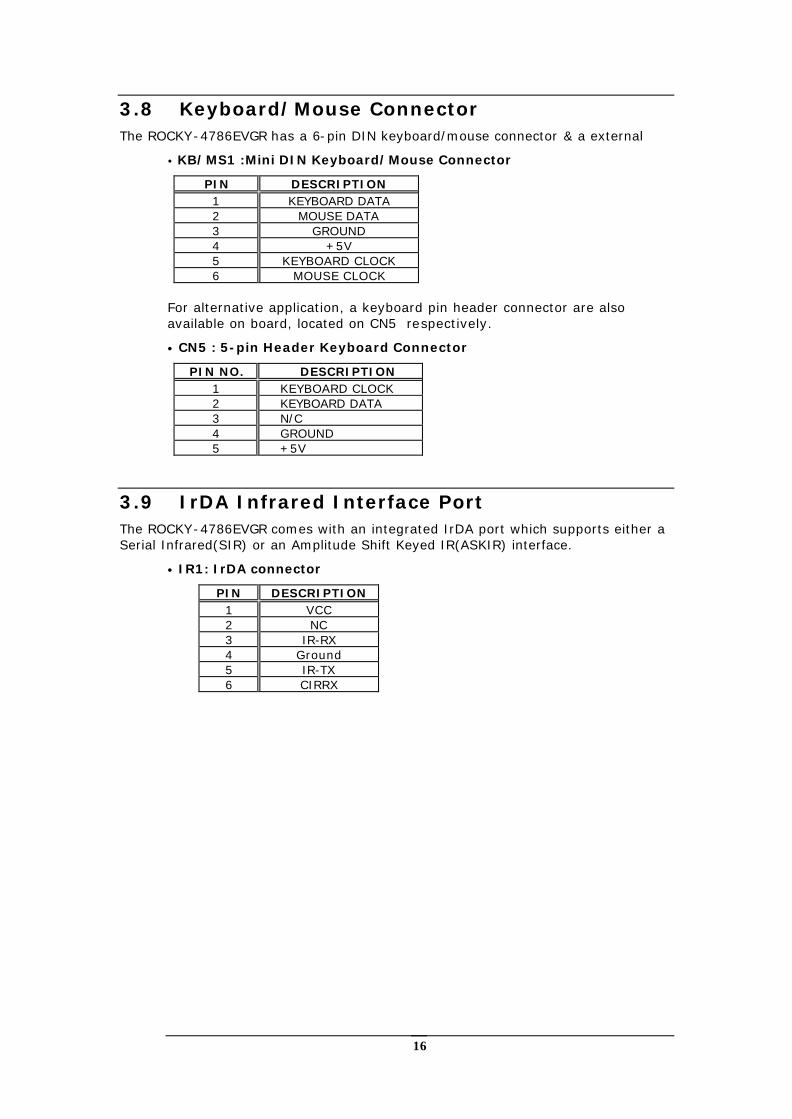
3.8 Keyboard/Mouse Connector The ROCKY-4786EVGR has a 6-pin DIN keyboard/mouse connector & a external
• KB/MS1 :Mini DIN Keyboard/Mouse Connector
PIN DESCRIPTION 1 KEYBOARD DATA 2 MOUSE DATA 3 GROUND 4 +5V 5 KEYBOARD CLOCK 6 MOUSE CLOCK
For alternative application, a keyboard pin header connector are also available on board, located on CN5 respectively.
• CN5 : 5-pin Header Keyboard Connector
PIN NO. DESCRIPTION 1 KEYBOARD CLOCK 2 KEYBOARD DATA 3 N/C 4 GROUND 5 +5V
3.9 IrDA Infrared Interface Port The ROCKY-4786EVGR comes with an integrated IrDA port which supports either a Serial Infrared(SIR) or an Amplitude Shift Keyed IR(ASKIR) interface.
• IR1: IrDA connector
PIN DESCRIPTION 1 VCC 2 NC 3 IR-RX 4 Ground 5 IR-TX 6 CIRRX
17
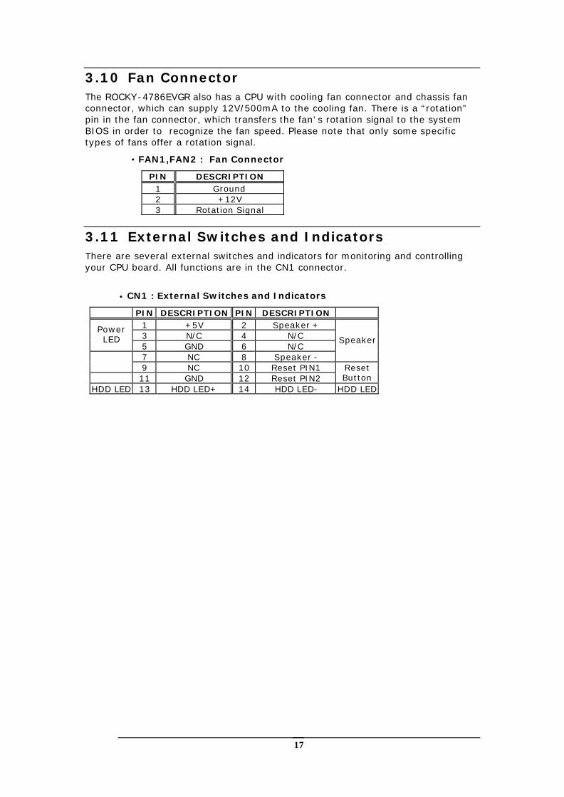
3.10 Fan Connector The ROCKY-4786EVGR also has a CPU with cooling fan connector and chassis fan connector, which can supply 12V/500mA to the cooling fan. There is a “rotation” pin in the fan connector, which transfers the fan’s rotation signal to the system BIOS in order to recognize the fan speed. Please note that only some specific types of fans offer a rotation signal.
• FAN1,FAN2 : Fan Connector
PIN DESCRIPTION 1 Ground 2 +12V 3 Rotation Signal
3.11 External Switches and Indicators There are several external switches and indicators for monitoring and controlling your CPU board. All functions are in the CN1 connector.
• CN1 : External Switches and Indicators
PIN DESCRIPTION PIN DESCRIPTION 1 +5V 2 Speaker + 3 N/C 4 N/C
Power LED
5 GND 6 N/C 7 NC 8 Speaker -
Speaker
9 NC 10 Reset PIN1
11 GND 12 Reset PIN2 Reset Button
HDD LED 13 HDD LED+ 14 HDD LED- HDD LED
18
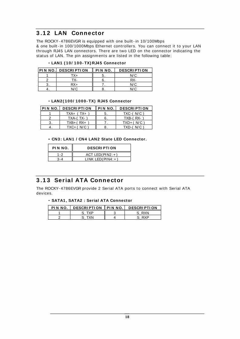
3.12 LAN Connector The ROCKY-4786EVGR is equipped with one built-in 10/100Mbps & one built-in 100/1000Mbps Ethernet controllers. You can connect it to your LAN through RJ45 LAN connectors. There are two LED on the connector indicating the status of LAN. The pin assignments are listed in the following table:
• LAN1 (10/100-TX)RJ45 Connector
PIN NO. DESCRIPTION PIN NO. DESCRIPTION 1 TX+ 5. N/C 2 TX- 6. RX- 3. RX+ 7. N/C 4. N/C 8. N/C
• LAN2(100/1000-TX) RJ45 Connector
PIN NO. DESCRIPTION PIN NO. DESCRIPTION 1 TXA+ ( TX+ ) 5. TXC-( N/C ) 2 TXA-( TX- ) 6. TXB-( RX- ) 3. TXB+( RX+ ) 7. TXD+( N/C ) 4. TXC+( N/C ) 8. TXD-( N/C )
• CN3: LAN1 /CN4 LAN2 State LED Connector.
PIN NO. DESCRIPTION
1-2 ACT LED(PIN2:+) 3-4 LINK LED(PIN4:+)
3.13 Serial ATA Connector The ROCKY-4786EVGR provide 2 Serial ATA ports to connect with Serial ATA devices.
• SATA1, SATA2 : Serial ATA Connector
PIN NO. DESCRIPTION PIN NO. DESCRIPTION 1 S_TXP 3 S_RXN 2 S_TXN 4 S_RXP
19
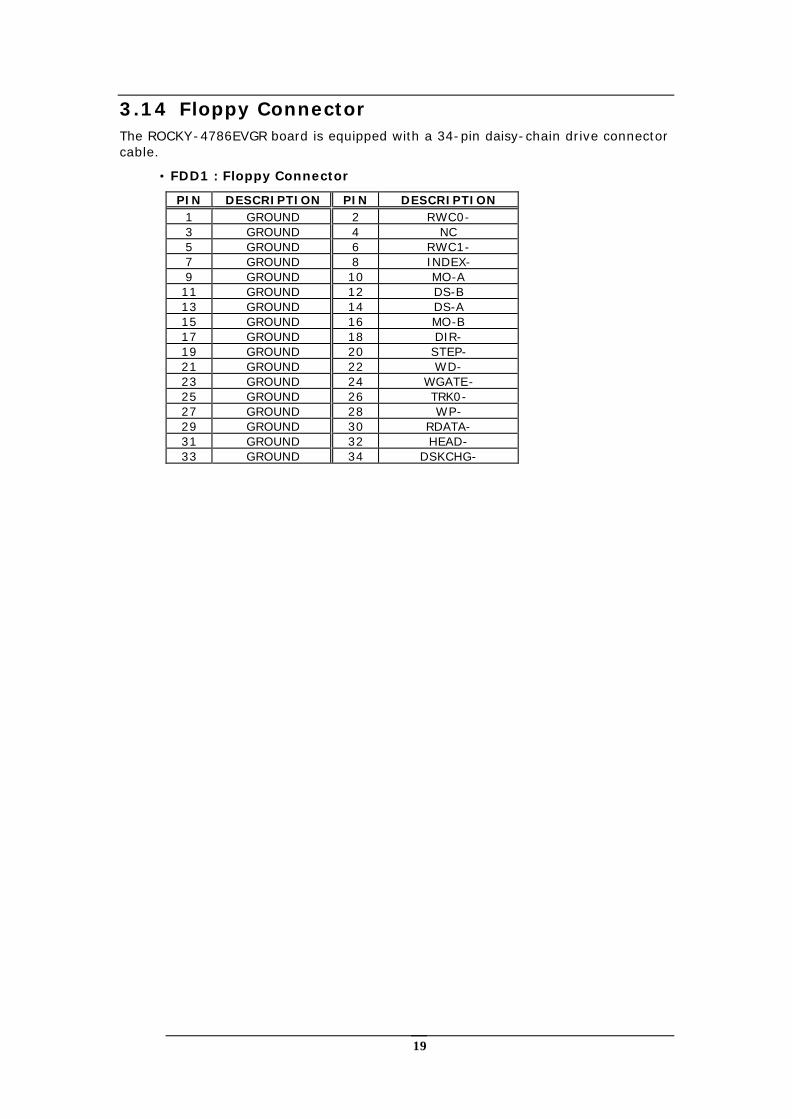
3.14 Floppy Connector The ROCKY-4786EVGR board is equipped with a 34-pin daisy-chain drive connector cable.
• FDD1 : Floppy Connector
PIN DESCRIPTION PIN DESCRIPTION 1 GROUND 2 RWC0- 3 GROUND 4 NC 5 GROUND 6 RWC1- 7 GROUND 8 INDEX- 9 GROUND 10 MO-A 11 GROUND 12 DS-B 13 GROUND 14 DS-A 15 GROUND 16 MO-B 17 GROUND 18 DIR- 19 GROUND 20 STEP- 21 GROUND 22 WD- 23 GROUND 24 WGATE- 25 GROUND 26 TRK0- 27 GROUND 28 WP- 29 GROUND 30 RDATA- 31 GROUND 32 HEAD- 33 GROUND 34 DSKCHG-
20
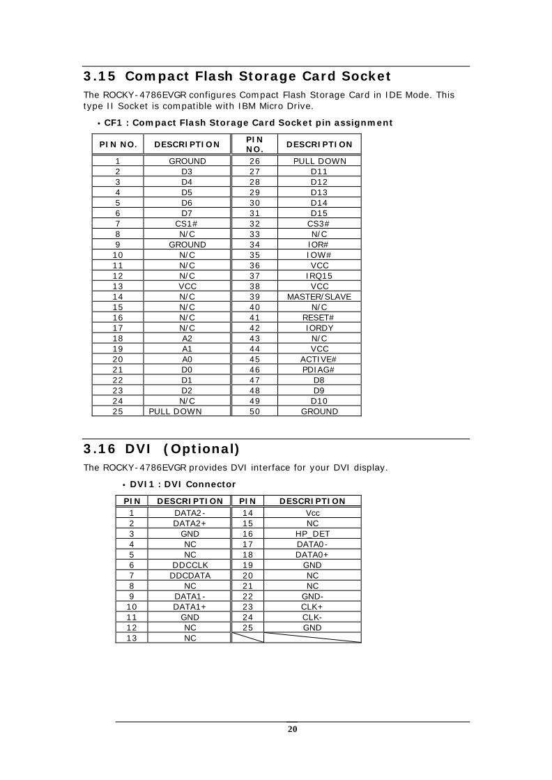
3.15 Compact Flash Storage Card Socket The ROCKY-4786EVGR configures Compact Flash Storage Card in IDE Mode. This type II Socket is compatible with IBM Micro Drive.
• CF1 : Compact Flash Storage Card Socket pin assignment
PIN NO. DESCRIPTION PIN NO. DESCRIPTION
1 GROUND 26 PULL DOWN 2 D3 27 D11 3 D4 28 D12 4 D5 29 D13 5 D6 30 D14 6 D7 31 D15 7 CS1# 32 CS3# 8 N/C 33 N/C 9 GROUND 34 IOR# 10 N/C 35 IOW# 11 N/C 36 VCC 12 N/C 37 IRQ15 13 VCC 38 VCC 14 N/C 39 MASTER/SLAVE 15 N/C 40 N/C 16 N/C 41 RESET# 17 N/C 42 IORDY 18 A2 43 N/C 19 A1 44 VCC 20 A0 45 ACTIVE# 21 D0 46 PDIAG# 22 D1 47 D8 23 D2 48 D9 24 N/C 49 D10 25 PULL DOWN 50 GROUND
3.16 DVI (Optional) The ROCKY-4786EVGR provides DVI interface for your DVI display.
• DVI1 : DVI Connector
PIN DESCRIPTION PIN DESCRIPTION 1 DATA2- 14 Vcc 2 DATA2+ 15 NC 3 GND 16 HP_DET 4 NC 17 DATA0- 5 NC 18 DATA0+ 6 DDCCLK 19 GND 7 DDCDATA 20 NC 8 NC 21 NC 9 DATA1- 22 GND- 10 DATA1+ 23 CLK+ 11 GND 24 CLK- 12 NC 25 GND 13 NC

21
3.17 ATXCTL Connector • ATXCTL : Backplane to Mainboard Connector
PIN NO. DESCRIPTION 1 5VSB 2 ATX-ON 3 GND
H Power source from Backplane with ATX Connector (Through Power Button & +5VSB)
22
Chapter 4 AMI BIOS Setup
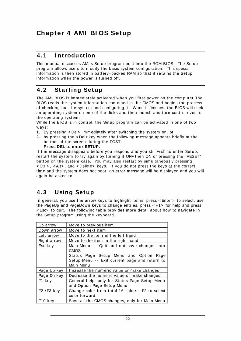
4.1 Introduction This manual discusses AMI's Setup program built into the ROM BIOS. The Setup program allows users to modify the basic system configuration. This special information is then stored in battery-backed RAM so that it retains the Setup information when the power is turned off.
4.2 Starting Setup The AMI BIOS is immediately activated when you first power on the computer.The BIOS reads the system information contained in the CMOS and begins the process of checking out the system and configuring it. When it finishes, the BIOS will seek an operating system on one of the disks and then launch and turn control over to the operating system. While the BIOS is in control, the Setup program can be activated in one of two ways: 1. By pressing <Del> immediately after switching the system on, or 2. by pressing the <Del>key when the following message appears briefly at the
bottom of the screen during the POST. Press DEL to enter SETUP.
If the message disappears before you respond and you still wish to enter Setup, restart the system to try again by turning it OFF then ON or pressing the "RESET" button on the system case. You may also restart by simultaneously pressing <Ctrl>, <Alt>, and <Delete> keys. If you do not press the keys at the correct time and the system does not boot, an error message will be displayed and you will again be asked to...
4.3 Using Setup In general, you use the arrow keys to highlight items, press <Enter> to select, use the PageUp and PageDown keys to change entries, press <F1> for help and press <Esc> to quit. The following table provides more detail about how to navigate in the Setup program using the keyboard.
Up arrow Move to previous item Down arrow Move to next item Left arrow Move to the item in the left hand Right arrow Move to the item in the right hand Esc key Main Menu -- Quit and not save changes into
CMOS Status Page Setup Menu and Option Page Setup Menu -- Exit current page and return to Main Menu
Page Up key Increase the numeric value or make changes Page Dn key Decrease the numeric value or make changes F1 key General help, only for Status Page Setup Menu
and Option Page Setup Menu F2 /F3 key Change color from total 16 colors. F2 to select
color forward. F10 key Save all the CMOS changes, only for Main Menu
23
4.4 Getting Help Press F1 to pop up a small help window that describes the appropriate keys to use and the possible selections for the highlighted item. To exit the Help Window press <Esc> or the F1 key again.
If, after making and saving system changes with Setup, you discover that your computer no longer is able to boot, the AMI BIOS supports an override to the CMOS settings which resets your system to its defaults.
The best advice is to only alter settings which you thoroughly understand. To this end, we strongly recommend that you avoid making any changes to the chipset defaults. These defaults have been carefully chosen by both AMI and your systems manufacturer to provide the absolute maximum performance and reliability. Even a seemingly small change to the chipset setup has the potential for causing you to use the override.
4.5 BIOS menu bar The menu bar on top of the screen has the following main items: Main For changing the basic system configuration. Advanced For changing the advanced system settings. PCI PnP This entry appears if your system supports PnP / PCI. Boot For changing the system boot configuration. Security Use this menu to set User and Supervisor Passwords. Chipset For changing the chipset setting. Power For changing the advanced power management configuration. Exit For selecting the exit options and loading default settings.
24
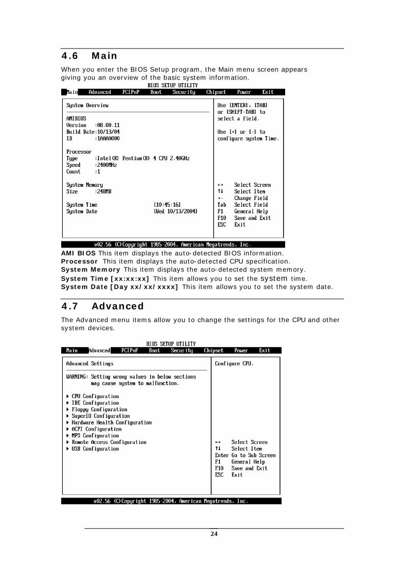
4.6 Main When you enter the BIOS Setup program, the Main menu screen appears giving you an overview of the basic system information.
AMI BIOS This item displays the auto-detected BIOS information. Processor This item displays the auto-detected CPU specification. System Memory This item displays the auto-detected system memory. System Time [xx:xx:xx] This item allows you to set the system time. System Date [Day xx/xx/xxxx] This item allows you to set the system date.
4.7 Advanced The Advanced menu items allow you to change the settings for the CPU and other system devices.
25
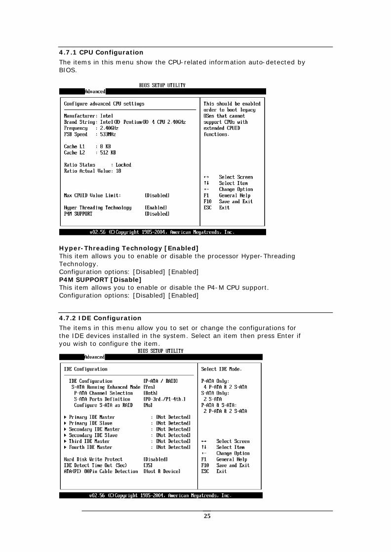
4.7.1 CPU Configuration
The items in this menu show the CPU-related information auto-detected by BIOS.
Hyper-Threading Technology [Enabled] This item allows you to enable or disable the processor Hyper-Threading Technology. Configuration options: [Disabled] [Enabled] P4M SUPPORT [Disable] This item allows you to enable or disable the P4-M CPU support. Configuration options: [Disabled] [Enabled]
4.7.2 IDE Configuration
The items in this menu allow you to set or change the configurations for the IDE devices installed in the system. Select an item then press Enter if you wish to configure the item.
26
IDE Configuration [P-ATA/RAID] This item allows you to select the IDE mode Configuration options: [Disabled] [P-ATA/RAID] [S-ATA Only] [P-ATA/S-ATA] Primary and Secondary IDE Master/Slave Third and Fourth IDE Master The values opposite the dimmed items (Device, Vendor, Size, LBA Mode, Block Mode, PIO Mode, Async DMA, Ultra DMA, and SMART monitoring) are auto-detected by BIOS and are not user-configurable. These items show N/A if no IDE device is installed in the system. Type [Auto] Selects the type of IDE drive. Setting to Auto allows automatic selection of the appropriate IDE device type. Select CDROM if you are specifically configuring a CD-ROM drive. Select ARMD (ATAPI Removable Media Device) if your device is either a ZIP, LS-120, or MO drive. Configuration options: [Not Installed] [Auto] [CDROM] [ARMD]. LBA/Large Mode [Auto] Enables or disables the LBA mode. Setting to Auto enables the LBA mode if the device supports this mode, and if the device was not previously formatted with LBA mode disabled. Configuration options: [Disabled] [Auto] Block (Multi-sector Transfer) [Auto] Enables or disables data multi-sectors transfers. When set to Auto, the data transfer from and to the device occurs multiple sectors at a time if the device supports multi-sector transfer feature. When set to Disabled, the data transfer from and to the device occurs one sector at a time. Configuration options: [Disabled] [Auto] PIO Mode [Auto] Selects the PIO mode. Configuration options: [Auto] [0] [1] [2] [3] [4] DMA Mode [Auto] Selects the DMA mode. Configuration options: [Auto] [SWDMA0] [SWDMA1] [SWDMA2] [MWDMA0] [MWDMA1] [MWDMA2] [UDMA0] [UDMA1] [UDMA2] [UDMA3] [UDMA4] [UDMA5] SMART Monitoring [Auto] Sets the Smart Monitoring, Analysis, and Reporting Technology. Configuration options: [Auto] [Disabled] [Enabled] 32Bit Data Transfer [Disabled] Enables or disables 32-bit data transfer. Configuration options:[Disabled] [Enabled] Hard Disk Write protect [Disabled] This item allows you to enable or disable the hard disk write protect Configuration options: [Disabled] [Enabled] IDE Detect Time Out (Sec) [35] Selects the time out value for detecting ATA/ATAPI devices. Configuration options: [0] [5] [10] [15] [20] [25] [30] [35] ATA(PI) 80Pin Cable Detection [Host & Device] Configuration options: [Host & Device] [Host] [Device]
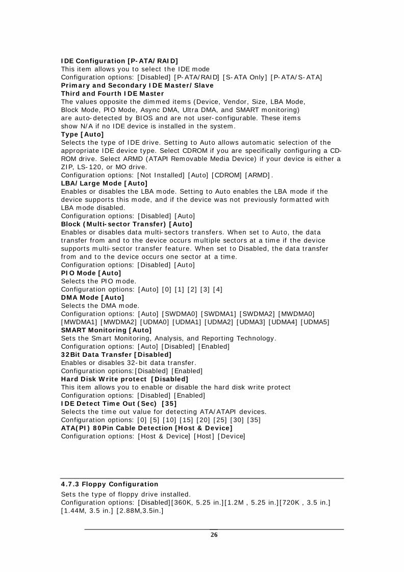
4.7.3 Floppy Configuration
Sets the type of floppy drive installed. Configuration options: [Disabled][360K, 5.25 in.][1.2M , 5.25 in.][720K , 3.5 in.] [1.44M, 3.5 in.] [2.88M,3.5in.]
27
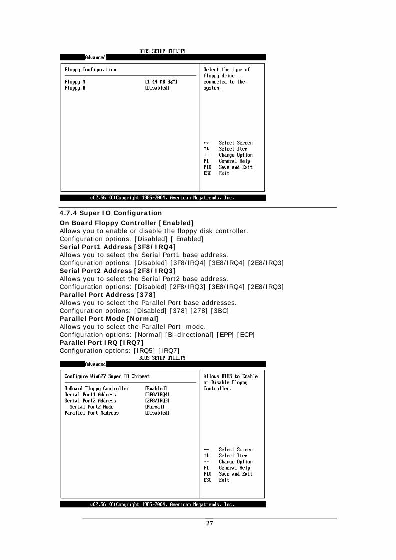
4.7.4 Super IO Configuration
On Board Floppy Controller [Enabled] Allows you to enable or disable the floppy disk controller. Configuration options: [Disabled] [ Enabled] Serial Port1 Address [3F8/IRQ4] Allows you to select the Serial Port1 base address. Configuration options: [Disabled] [3F8/IRQ4] [3E8/IRQ4] [2E8/IRQ3] Serial Port2 Address [2F8/IRQ3] Allows you to select the Serial Port2 base address. Configuration options: [Disabled] [2F8/IRQ3] [3E8/IRQ4] [2E8/IRQ3] Parallel Port Address [378] Allows you to select the Parallel Port base addresses. Configuration options: [Disabled] [378] [278] [3BC] Parallel Port Mode [Normal] Allows you to select the Parallel Port mode. Configuration options: [Normal] [Bi-directional] [EPP] [ECP] Parallel Port IRQ [IRQ7] Configuration options: [IRQ5] [IRQ7]
28
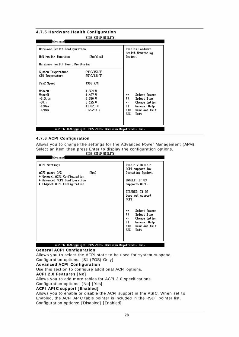
4.7.5 Hardware Health Configuration
4.7.6 ACPI Configuration
Allows you to change the settings for the Advanced Power Management (APM). Select an item then press Enter to display the configuration options.
General ACPI Configuration Allows you to select the ACPI state to be used for system suspend. Configuration options: [S1 (POS) Only] Advanced ACPI Configuration Use this section to configure additional ACPI options. ACPI 2.0 Features [No] Allows you to add more tables for ACPI 2.0 specifications. Configuration options: [No] [Yes] ACPI APIC support [Enabled] Allows you to enable or disable the ACPI support in the ASIC. When set to Enabled, the ACPI APIC table pointer is included in the RSDT pointer list. Configuration options: [Disabled] [Enabled]
29
AMI OEMB table [Enabled] Allows you to enable or disable the inclusion of the BIOS ->AML exchange pointer to (X)RSDT pointer list. Configuration options: [Disabled] [Enabled] Headless mode [Disabled] Enable/Disable headless operation mode through ACPI.
4.7.7 MPS Configuration
Configure the Multi-Processor table MPS Revision [1.4] Configuration options: [1.1] [1.4]
4.7.8 Remote Access Configuration
Configure Remote Access. Remote Access [Disabled] Configuration options: [Disabled] [Enabled]
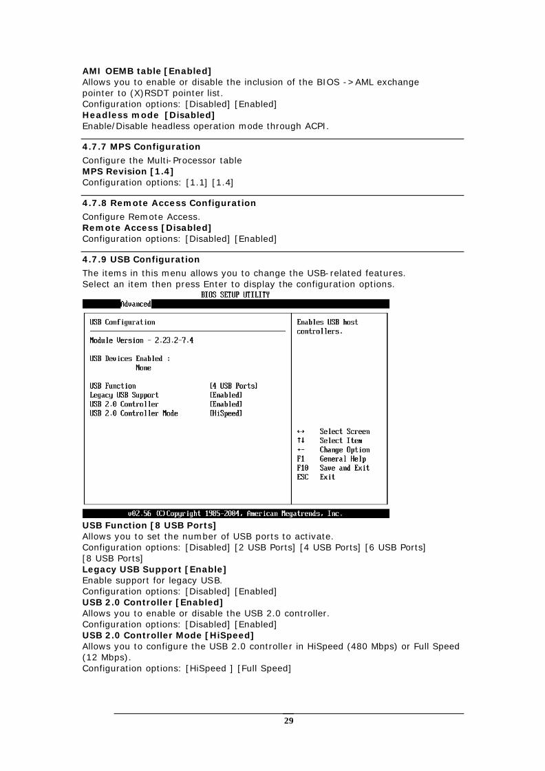
4.7.9 USB Configuration
The items in this menu allows you to change the USB-related features. Select an item then press Enter to display the configuration options.
USB Function [8 USB Ports] Allows you to set the number of USB ports to activate. Configuration options: [Disabled] [2 USB Ports] [4 USB Ports] [6 USB Ports] [8 USB Ports] Legacy USB Support [Enable] Enable support for legacy USB. Configuration options: [Disabled] [Enabled] USB 2.0 Controller [Enabled] Allows you to enable or disable the USB 2.0 controller. Configuration options: [Disabled] [Enabled] USB 2.0 Controller Mode [HiSpeed] Allows you to configure the USB 2.0 controller in HiSpeed (480 Mbps) or Full Speed (12 Mbps). Configuration options: [HiSpeed ] [Full Speed]
30
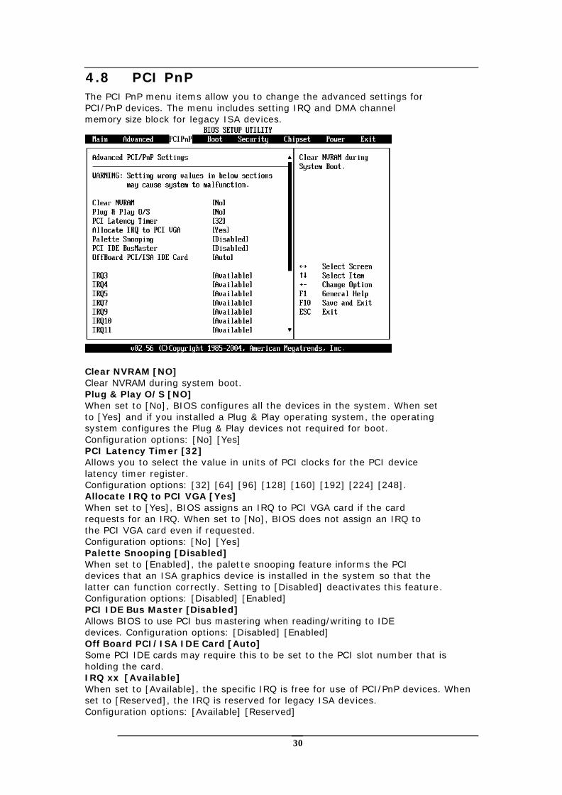
4.8 PCI PnP The PCI PnP menu items allow you to change the advanced settings for PCI/PnP devices. The menu includes setting IRQ and DMA channel memory size block for legacy ISA devices.
Clear NVRAM [NO] Clear NVRAM during system boot. Plug & Play O/S [NO] When set to [No], BIOS configures all the devices in the system. When set to [Yes] and if you installed a Plug & Play operating system, the operating system configures the Plug & Play devices not required for boot. Configuration options: [No] [Yes] PCI Latency Timer [32] Allows you to select the value in units of PCI clocks for the PCI device latency timer register. Configuration options: [32] [64] [96] [128] [160] [192] [224] [248]. Allocate IRQ to PCI VGA [Yes] When set to [Yes], BIOS assigns an IRQ to PCI VGA card if the card requests for an IRQ. When set to [No], BIOS does not assign an IRQ to the PCI VGA card even if requested. Configuration options: [No] [Yes] Palette Snooping [Disabled] When set to [Enabled], the palette snooping feature informs the PCI devices that an ISA graphics device is installed in the system so that the latter can function correctly. Setting to [Disabled] deactivates this feature. Configuration options: [Disabled] [Enabled] PCI IDE Bus Master [Disabled] Allows BIOS to use PCI bus mastering when reading/writing to IDE devices. Configuration options: [Disabled] [Enabled] Off Board PCI/ISA IDE Card [Auto] Some PCI IDE cards may require this to be set to the PCI slot number that is holding the card. IRQ xx [Available] When set to [Available], the specific IRQ is free for use of PCI/PnP devices. When set to [Reserved], the IRQ is reserved for legacy ISA devices. Configuration options: [Available] [Reserved]
31
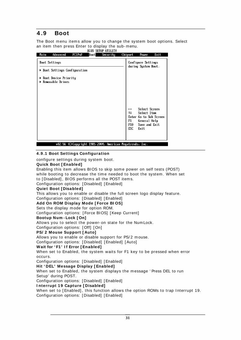
4.9 Boot The Boot menu items allow you to change the system boot options. Select an item then press Enter to display the sub-menu.
4.9.1 Boot Settings Configuration
configure settings during system boot. Quick Boot [Enabled] Enabling this item allows BIOS to skip some power on self tests (POST) while booting to decrease the time needed to boot the system. When set to [Disabled], BIOS performs all the POST items. Configuration options: [Disabled] [Enabled] Quiet Boot [Disabled] This allows you to enable or disable the full screen logo display feature. Configuration options: [Disabled] [Enabled] Add On ROM Display Mode [Force BIOS] Sets the display mode for option ROM. Configuration options: [Force BIOS] [Keep Current] Bootup Num-Lock [On] Allows you to select the power-on state for the NumLock. Configuration options: [Off] [On] PS/2 Mouse Support [Auto] Allows you to enable or disable support for PS/2 mouse. Configuration options: [Disabled] [Enabled] [Auto] Wait for ‘F1’ If Error [Enabled] When set to Enabled, the system waits for F1 key to be pressed when error occurs. Configuration options: [Disabled] [Enabled] Hit ‘DEL’ Message Display [Enabled] When set to Enabled, the system displays the message ‘Press DEL to run Setup’ during POST. Configuration options: [Disabled] [Enabled] Interrupt 19 Capture [Disabled] When set to [Enabled], this function allows the option ROMs to trap Interrupt 19. Configuration options: [Disabled] [Enabled]
32
4.9.2 Boot Device Priority
Specifies the boot device priority sequence.
1st ~ xxth Boot Device These items specify the boot device priority sequence from the available hard disk drives. The number of items that appear on the screen depends on the number of hard disk drives installed in the system. Configuration options: [xxxxx Drive] [Disabled] Removable Drives Specifies the boot device priority sequence from available removable drives.
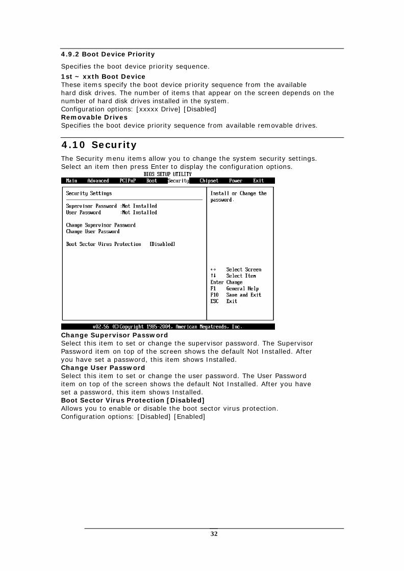
4.10 Security The Security menu items allow you to change the system security settings. Select an item then press Enter to display the configuration options.
Change Supervisor Password Select this item to set or change the supervisor password. The Supervisor Password item on top of the screen shows the default Not Installed. After you have set a password, this item shows Installed. Change User Password Select this item to set or change the user password. The User Password item on top of the screen shows the default Not Installed. After you have set a password, this item shows Installed. Boot Sector Virus Protection [Disabled] Allows you to enable or disable the boot sector virus protection. Configuration options: [Disabled] [Enabled]
33
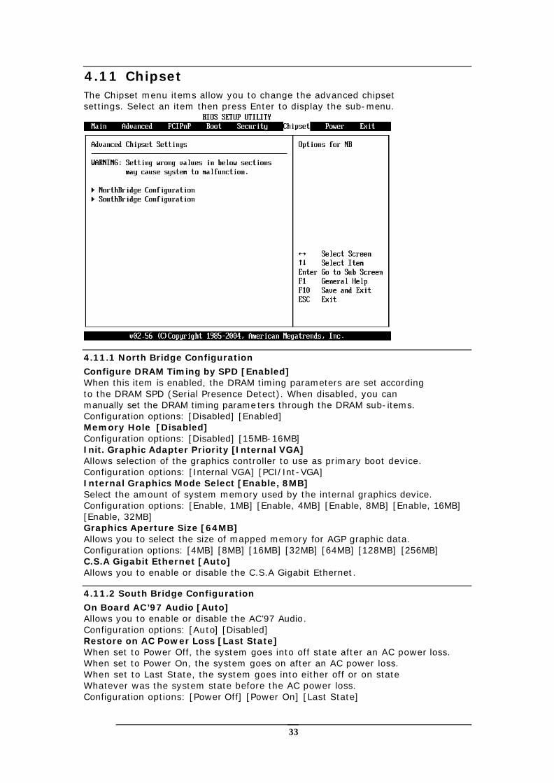
4.11 Chipset The Chipset menu items allow you to change the advanced chipset settings. Select an item then press Enter to display the sub-menu.
4.11.1 North Bridge Configuration
Configure DRAM Timing by SPD [Enabled] When this item is enabled, the DRAM timing parameters are set according to the DRAM SPD (Serial Presence Detect). When disabled, you can manually set the DRAM timing parameters through the DRAM sub-items. Configuration options: [Disabled] [Enabled] Memory Hole [Disabled] Configuration options: [Disabled] [15MB-16MB] Init. Graphic Adapter Priority [Internal VGA] Allows selection of the graphics controller to use as primary boot device. Configuration options: [Internal VGA] [PCI/Int-VGA] Internal Graphics Mode Select [Enable, 8MB] Select the amount of system memory used by the internal graphics device. Configuration options: [Enable, 1MB] [Enable, 4MB] [Enable, 8MB] [Enable, 16MB] [Enable, 32MB] Graphics Aperture Size [64MB] Allows you to select the size of mapped memory for AGP graphic data. Configuration options: [4MB] [8MB] [16MB] [32MB] [64MB] [128MB] [256MB] C.S.A Gigabit Ethernet [Auto] Allows you to enable or disable the C.S.A Gigabit Ethernet.
4.11.2 South Bridge Configuration
On Board AC’97 Audio [Auto] Allows you to enable or disable the AC’97 Audio. Configuration options: [Auto] [Disabled] Restore on AC Power Loss [Last State] When set to Power Off, the system goes into off state after an AC power loss. When set to Power On, the system goes on after an AC power loss. When set to Last State, the system goes into either off or on state Whatever was the system state before the AC power loss. Configuration options: [Power Off] [Power On] [Last State]
34
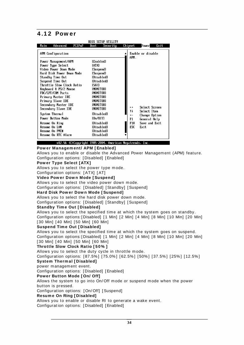
4.12 Power
Power Management/APM [Enabled] Allows you to enable or disable the Advanced Power Management (APM) feature. Configuration options: [Disabled] [Enabled] Power Type Select [ATX] Allows you to select the power type mode. Configuration options: [ATX] [AT] Video Power Down Mode [Suspend] Allows you to select the video power down mode. Configuration options: [Disabled] [Standby] [Suspend] Hard Disk Power Down Mode [Suspend] Allows you to select the hard disk power down mode. Configuration options: [Disabled] [Standby] [Suspend] Standby Time Out [Disabled] Allows you to select the specified time at which the system goes on standby. Configuration options:[Disabled] [1 Min] [2 Min] [4 Min] [8 Min] [10 Min] [20 Min] [30 Min] [40 Min] [50 Min] [60 Min] Suspend Time Out [Disabled] Allows you to select the specified time at which the system goes on suspend. Configuration options:[Disabled] [1 Min] [2 Min] [4 Min] [8 Min] [10 Min] [20 Min] [30 Min] [40 Min] [50 Min] [60 Min] Throttle Slow Clock Ratio [50%] Allows you to select the duty cycle in throttle mode. Configuration options: [87.5%] [75.0%] [62.5%] [50%] [37.5%] [25%] [12.5%] System Thermal [Disabled] power management event. Configuration options: [Disabled] [Enabled] Power Button Mode [On/Off] Allows the system to go into On/Off mode or suspend mode when the power button is pressed. Configuration options: [On/Off] [Suspend] Resume On Ring [Disabled] Allows you to enable or disable RI to generate a wake event. Configuration options: [Disabled] [Enabled]
35
Resume On LAN [Disabled] Allows you to enable or disable LAN GPI to generate a wake event. Configuration options: [Disabled] [Enabled] Resume On PME# [Disabled] Allows you to enable or disable PCI PME# to generate a wake event. Configuration options: [Disabled] [Enabled] Resume On RTC Alarm [Disabled] Allows you to enable or disable RTC to generate a wake event. When this item is set to Enabled, the items RTC Alarm Date, RTC Alarm Hour, RTC Alarm Minute, and RTC Alarm Second appear with set values. Configuration options: [Disabled] [Enabled]
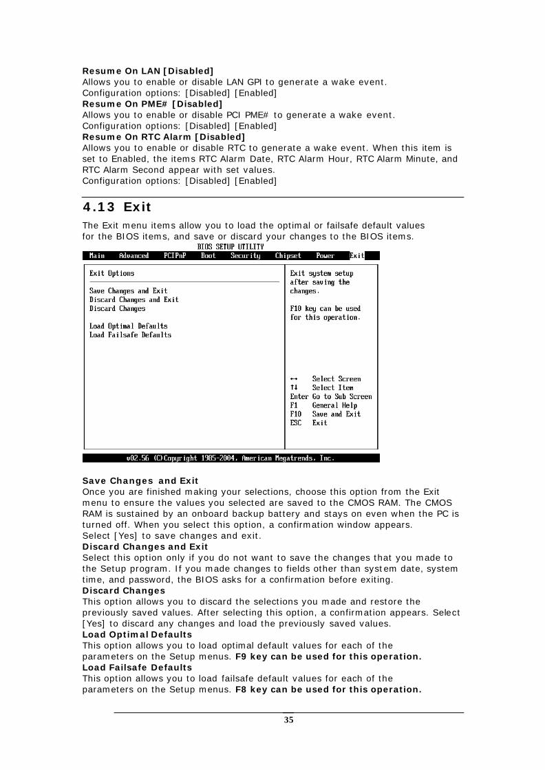
4.13 Exit The Exit menu items allow you to load the optimal or failsafe default values for the BIOS items, and save or discard your changes to the BIOS items.
Save Changes and Exit Once you are finished making your selections, choose this option from the Exit menu to ensure the values you selected are saved to the CMOS RAM. The CMOS RAM is sustained by an onboard backup battery and stays on even when the PC is turned off. When you select this option, a confirmation window appears. Select [Yes] to save changes and exit. Discard Changes and Exit Select this option only if you do not want to save the changes that you made to the Setup program. If you made changes to fields other than system date, system time, and password, the BIOS asks for a confirmation before exiting. Discard Changes This option allows you to discard the selections you made and restore the previously saved values. After selecting this option, a confirmation appears. Select [Yes] to discard any changes and load the previously saved values. Load Optimal Defaults This option allows you to load optimal default values for each of the parameters on the Setup menus. F9 key can be used for this operation. Load Failsafe Defaults This option allows you to load failsafe default values for each of the parameters on the Setup menus. F8 key can be used for this operation.
36
Appendix A Watchdog Timer
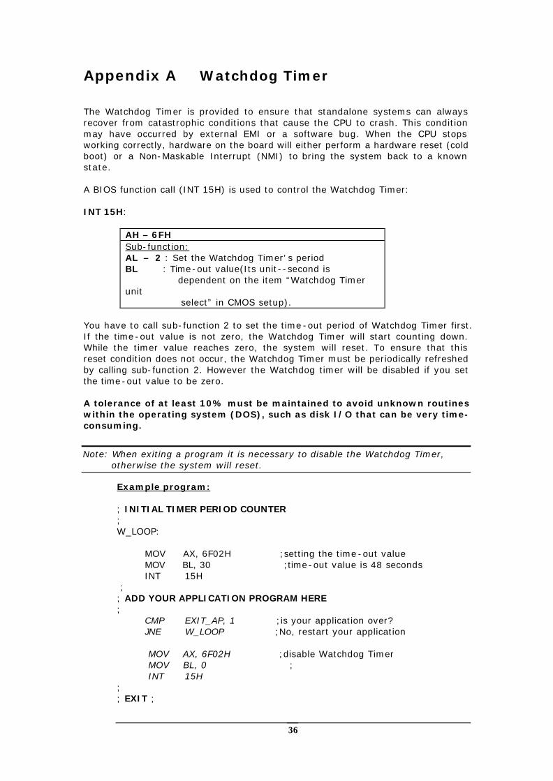
The Watchdog Timer is provided to ensure that standalone systems can always recover from catastrophic conditions that cause the CPU to crash. This condition may have occurred by external EMI or a software bug. When the CPU stops working correctly, hardware on the board will either perform a hardware reset (cold boot) or a Non-Maskable Interrupt (NMI) to bring the system back to a known state. A BIOS function call (INT 15H) is used to control the Watchdog Timer: INT 15H:
AH – 6FH Sub-function: AL – 2 : Set the Watchdog Timer’s period BL : Time-out value(Its unit--second is dependent on the item “Watchdog Timer unit select” in CMOS setup).
You have to call sub-function 2 to set the time-out period of Watchdog Timer first. If the time-out value is not zero, the Watchdog Timer will start counting down. While the timer value reaches zero, the system will reset. To ensure that this reset condition does not occur, the Watchdog Timer must be periodically refreshed by calling sub-function 2. However the Watchdog timer will be disabled if you set the time-out value to be zero. A tolerance of at least 10% must be maintained to avoid unknown routines within the operating system (DOS), such as disk I/O that can be very time-consuming.
Note: When exiting a program it is necessary to disable the Watchdog Timer, otherwise the system will reset.
Example program: ; INITIAL TIMER PERIOD COUNTER ; W_LOOP: MOV AX, 6F02H ;setting the time-out value MOV BL, 30 ;time-out value is 48 seconds INT 15H ; ; ADD YOUR APPLICATION PROGRAM HERE ; CMP EXIT_AP, 1 ;is your application over? JNE W_LOOP ;No, restart your application MOV AX, 6F02H ;disable Watchdog Timer MOV BL, 0 ; INT 15H ; ; EXIT ;
37
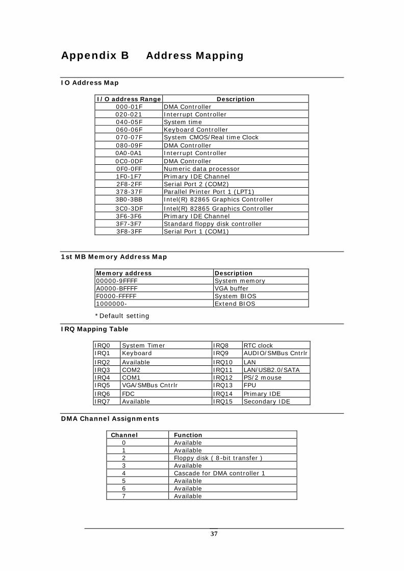
Appendix B Address Mapping
IO Address Map
I/O address Range Description 000-01F DMA Controller 020-021 Interrupt Controller 040-05F System time 060-06F Keyboard Controller 070-07F System CMOS/Real time Clock 080-09F DMA Controller 0A0-0A1 Interrupt Controller 0C0-0DF DMA Controller 0F0-0FF Numeric data processor 1F0-1F7 Primary IDE Channel 2F8-2FF Serial Port 2 (COM2) 378-37F Parallel Printer Port 1 (LPT1) 3B0-3BB Intel(R) 82865 Graphics Controller 3C0-3DF Intel(R) 82865 Graphics Controller 3F6-3F6 Primary IDE Channel 3F7-3F7 Standard floppy disk controller 3F8-3FF Serial Port 1 (COM1)
1st MB Memory Address Map
Memory address Description 00000-9FFFF System memory A0000-BFFFF VGA buffer F0000-FFFFF System BIOS 1000000- Extend BIOS
*Default setting
IRQ Mapping Table
IRQ0 System Timer IRQ8 RTC clock IRQ1 Keyboard IRQ9 AUDIO/SMBus Cntrlr IRQ2 Available IRQ10 LAN IRQ3 COM2 IRQ11 LAN/USB2.0/SATA IRQ4 COM1 IRQ12 PS/2 mouse IRQ5 VGA/SMBus Cntrlr IRQ13 FPU IRQ6 FDC IRQ14 Primary IDE IRQ7 Available IRQ15 Secondary IDE
DMA Channel Assignments
Channel Function 0 Available 1 Available 2 Floppy disk ( 8-bit transfer ) 3 Available 4 Cascade for DMA controller 1 5 Available 6 Available 7 Available
38
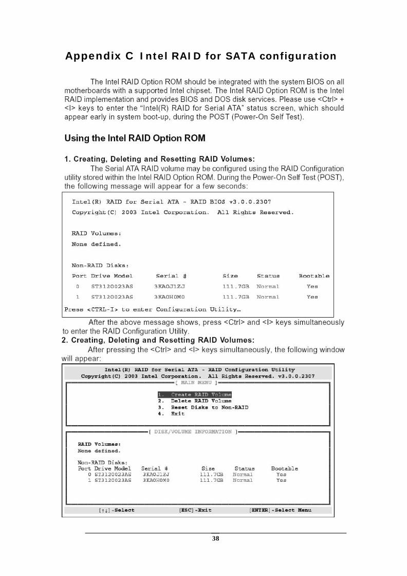
Appendix C Intel RAID for SATA configuration
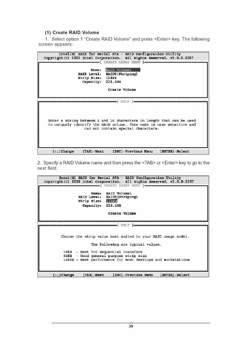
39
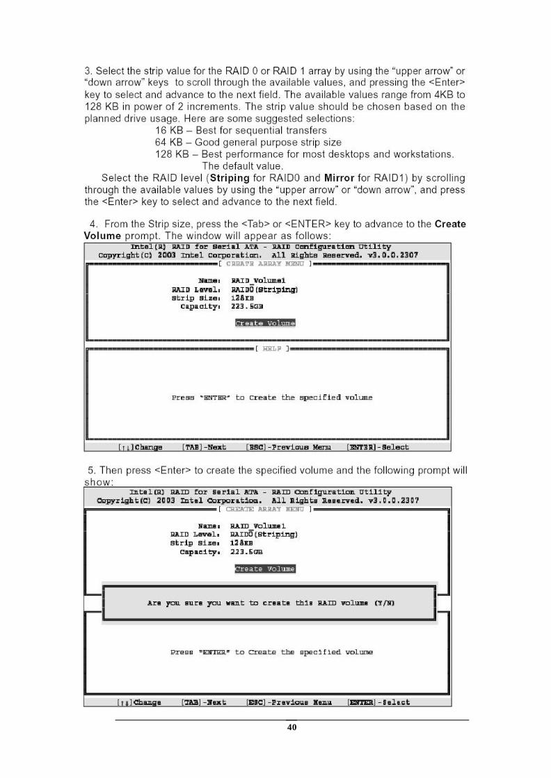
40
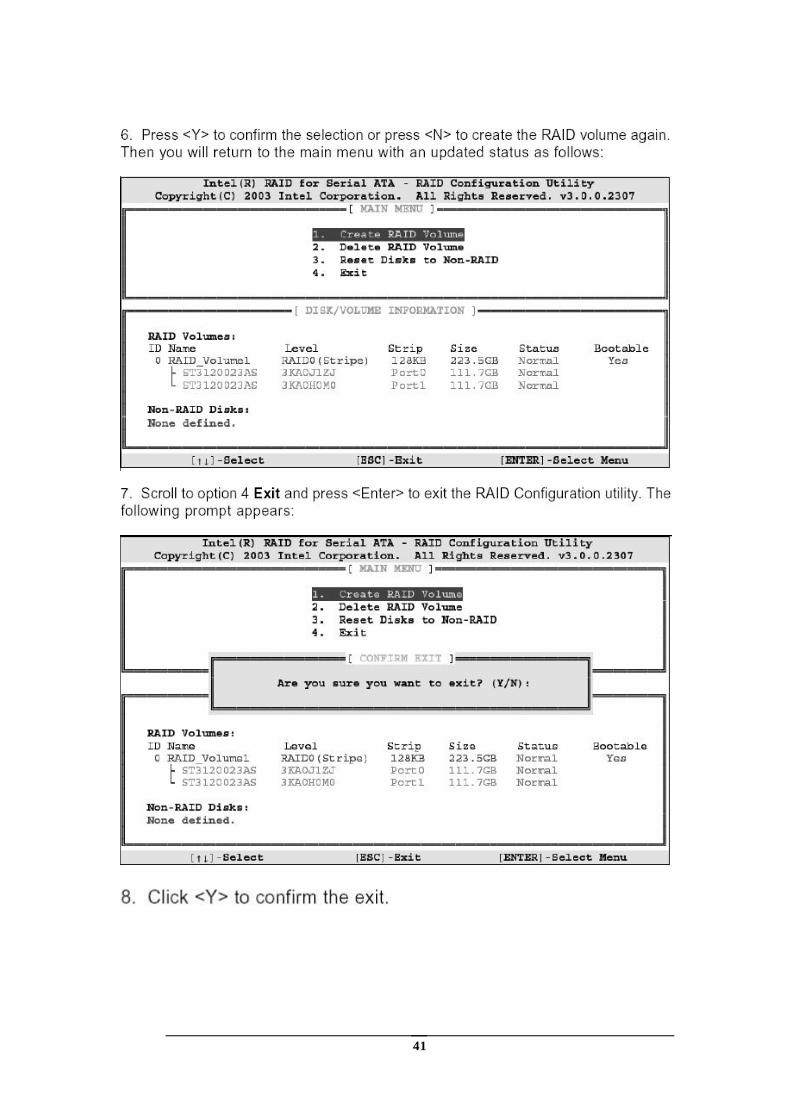
41
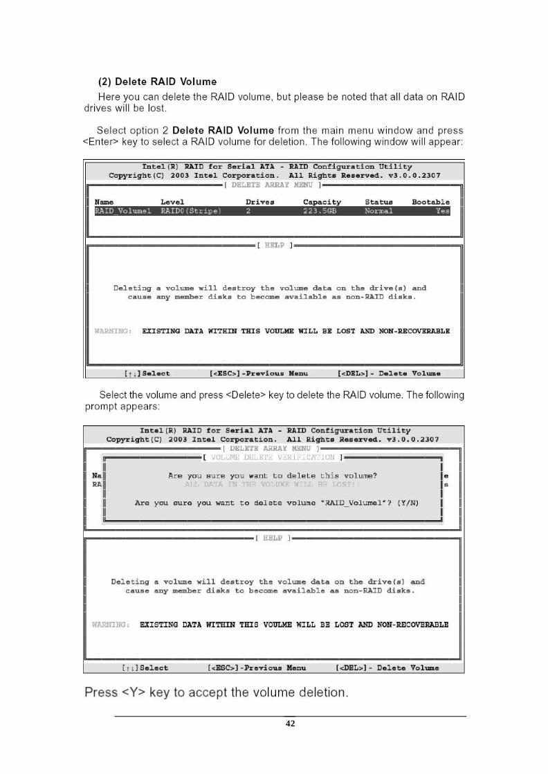
42
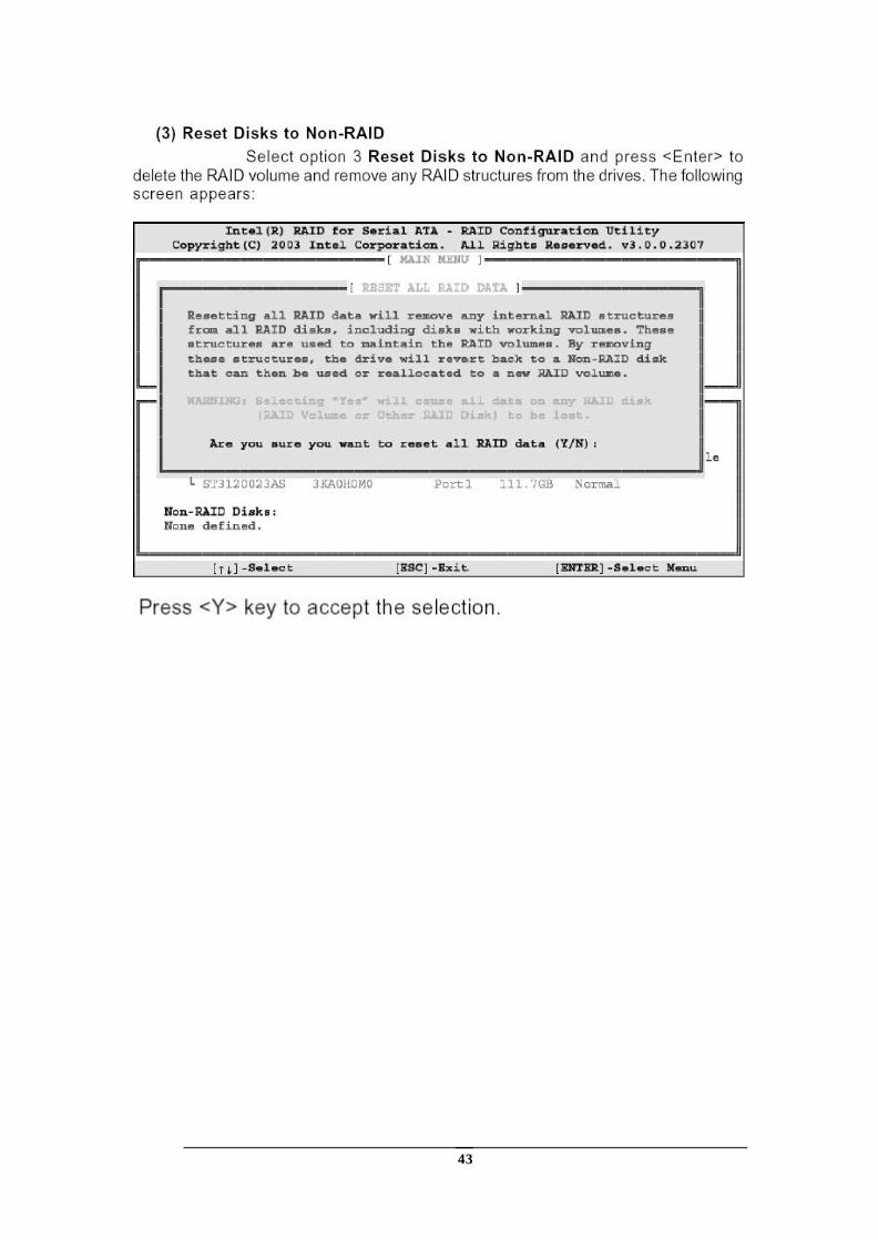
43
44
Appendix D AMI BIOS Setup
D.1 Introduction
This manual discusses AMI's Setup program built into the ROM BIOS. The Setup program allows users to modify the basic system configuration. This special information is then stored in battery-backed RAM so that it retains the Setup information when the power is turned off.
D.2 Starting Setup
The AMI BIOS is immediately activated when you first power on the computer.The BIOS reads the system information contained in the CMOS and begins the process of checking out the system and configuring it. When it finishes, the BIOS will seek an operating system on one of the disks and then launch and turn control over to the operating system.
While the BIOS is in control, the Setup program can be activated in one of two ways:
By pressing <Del> immediately after switching the system on, or
by pressing the <Del>key when the following message appears briefly at the bottom of the screen during the POST. Press DEL to enter SETUP.
If the message disappears before you respond and you still wish to enter Setup, restart the system to try again by turning it OFF then ON or pressing the "RESET" button on the system case. You may also restart by simultaneously pressing <Ctrl>, <Alt>, and <Delete> keys. If you do not press the keys at the correct time and the system does not boot, an error message will be displayed and you will again be asked to...
D.3 Using Setup
In general, you use the arrow keys to highlight items, press <Enter> to select, use the PageUp and PageDown keys to change entries, press <F1> for help and press <Esc> to quit. The following table provides more detail about how to navigate in the Setup program using the keyboard.
Up arrow Move to previous item Down arrow Move to next item Left arrow Move to the item in the left hand Right arrow Move to the item in the right hand Esc key Main Menu -- Quit and not save changes into
CMOS Status Page Setup Menu and Option Page Setup Menu -- Exit current page and return to Main Menu
Page Up key Increase the numeric value or make changes Page Dn key Decrease the numeric value or make changes F1 key General help, only for Status Page Setup Menu
45
and Option Page Setup Menu F2 /F3 key Change color from total 16 colors. F2 to select
color forward. F10 key Save all the CMOS changes, only for Main Menu
D.4 Getting Help
Press F1 to pop up a small help window that describes the appropriate keys to use and the possible selections for the highlighted item. To exit the Help Window press <Esc> or the F1 key again.
If, after making and saving system changes with Setup, you discover that your computer no longer is able to boot, the AMI BIOS supports an override to the CMOS settings which resets your system to its defaults.
The best advice is to only alter settings which you thoroughly understand. To this end, we strongly recommend that you avoid making any changes to the chipset defaults. These defaults have been carefully chosen by both AMI and your systems manufacturer to provide the absolute maximum performance and reliability. Even a seemingly small change to the chipset setup has the potential for causing you to use the override.
D.5 BIOS menu bar
The menu bar on top of the screen has the following main items:
Main For changing the basic system configuration.
Advanced For changing the advanced system settings.
PCI PnP This entry appears if your system supports PnP / PCI.
Boot For changing the system boot configuration.
Security Use this menu to set User and Supervisor Passwords.
Chipset For changing the chipset setting.
Power For changing the advanced power management configuration.
Exit For selecting the exit options and loading default settings.
46
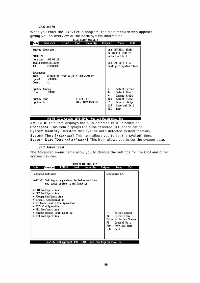
D.6 Main
When you enter the BIOS Setup program, the Main menu screen appears giving you an overview of the basic system information.
AMI BIOS This item displays the auto-detected BIOS information. Processor This item displays the auto-detected CPU specification. System Memory This item displays the auto-detected system memory. System Time [xx:xx:xx] This item allows you to set the system time. System Date [Day xx/xx/xxxx] This item allows you to set the system date.
D.7 Advanced
The Advanced menu items allow you to change the settings for the CPU and other system devices.
47
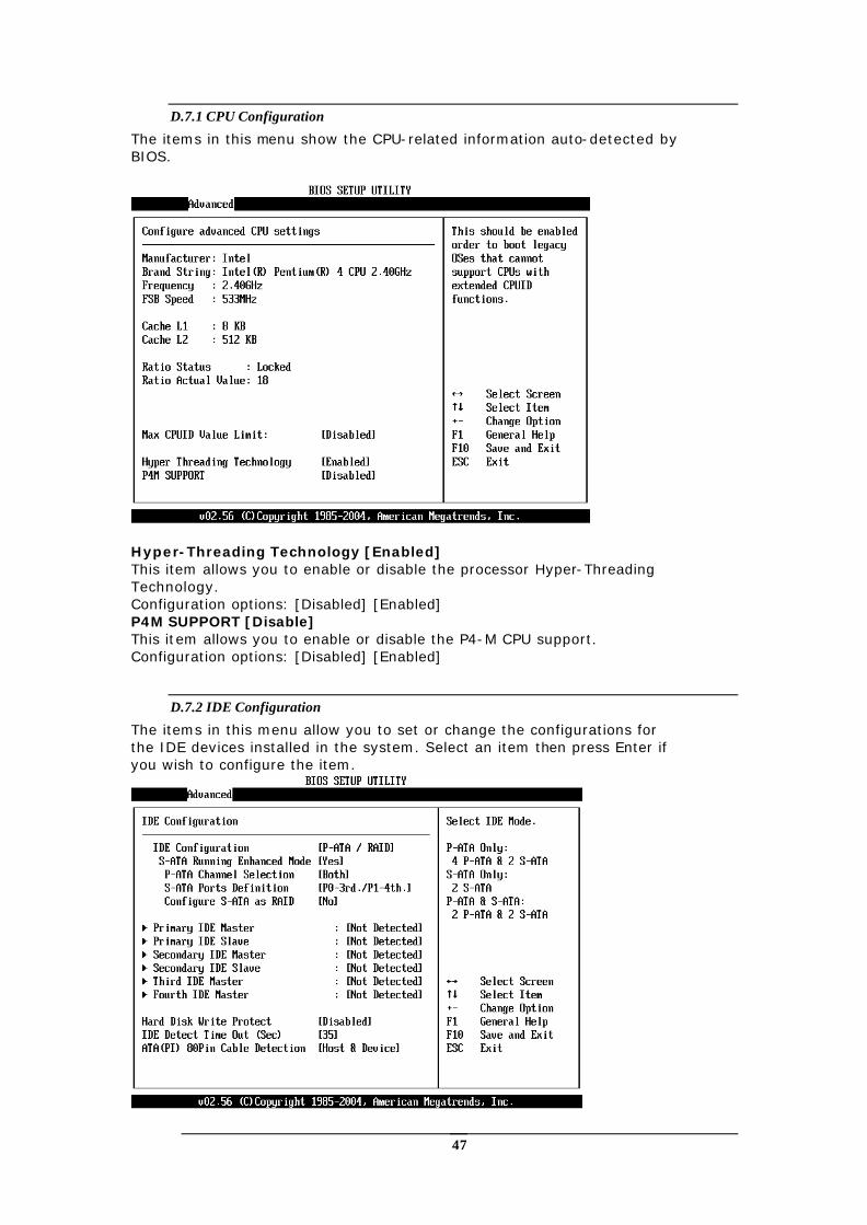
D.7.1 CPU Configuration
The items in this menu show the CPU-related information auto-detected by BIOS.
Hyper-Threading Technology [Enabled] This item allows you to enable or disable the processor Hyper-Threading Technology. Configuration options: [Disabled] [Enabled] P4M SUPPORT [Disable] This item allows you to enable or disable the P4-M CPU support. Configuration options: [Disabled] [Enabled]
D.7.2 IDE Configuration
The items in this menu allow you to set or change the configurations for the IDE devices installed in the system. Select an item then press Enter if you wish to configure the item.
48
IDE Configuration [P-ATA/RAID] This item allows you to select the IDE mode Configuration options: [Disabled] [P-ATA/RAID] [S-ATA Only] [P-ATA/S-ATA] Primary and Secondary IDE Master/Slave Third and Fourth IDE Master The values opposite the dimmed items (Device, Vendor, Size, LBA Mode, Block Mode, PIO Mode, Async DMA, Ultra DMA, and SMART monitoring) are auto-detected by BIOS and are not user-configurable. These items show N/A if no IDE device is installed in the system. Type [Auto] Selects the type of IDE drive. Setting to Auto allows automatic selection of the appropriate IDE device type. Select CDROM if you are specifically configuring a CD-ROM drive. Select ARMD (ATAPI Removable Media Device) if your device is either a ZIP, LS-120, or MO drive. Configuration options: [Not Installed] [Auto] [CDROM] [ARMD]. LBA/Large Mode [Auto] Enables or disables the LBA mode. Setting to Auto enables the LBA mode if the device supports this mode, and if the device was not previously formatted with LBA mode disabled. Configuration options: [Disabled] [Auto] Block (Multi-sector Transfer) [Auto] Enables or disables data multi-sectors transfers. When set to Auto, the data transfer from and to the device occurs multiple sectors at a time if the device supports multi-sector transfer feature. When set to Disabled, the data transfer from and to the device occurs one sector at a time. Configuration options: [Disabled] [Auto] PIO Mode [Auto] Selects the PIO mode. Configuration options: [Auto] [0] [1] [2] [3] [4] DMA Mode [Auto] Selects the DMA mode. Configuration options: [Auto] [SWDMA0] [SWDMA1] [SWDMA2] [MWDMA0] [MWDMA1] [MWDMA2] [UDMA0] [UDMA1] [UDMA2] [UDMA3] [UDMA4] [UDMA5] SMART Monitoring [Auto] Sets the Smart Monitoring, Analysis, and Reporting Technology. Configuration options: [Auto] [Disabled] [Enabled] 32Bit Data Transfer [Disabled] Enables or disables 32-bit data transfer. Configuration options:[Disabled] [Enabled] Hard Disk Write protect [Disabled] This item allows you to enable or disable the hard disk write protect Configuration options: [Disabled] [Enabled] IDE Detect Time Out (Sec) [35] Selects the time out value for detecting ATA/ATAPI devices. Configuration options: [0] [5] [10] [15] [20] [25] [30] [35] ATA(PI) 80Pin Cable Detection [Host & Device] Configuration options: [Host & Device] [Host] [Device]
49
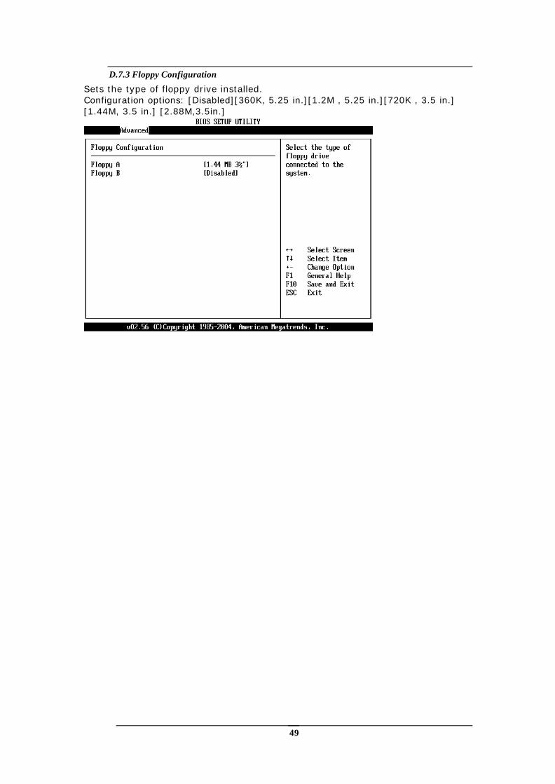
D.7.3 Floppy Configuration
Sets the type of floppy drive installed. Configuration options: [Disabled][360K, 5.25 in.][1.2M , 5.25 in.][720K , 3.5 in.] [1.44M, 3.5 in.] [2.88M,3.5in.]
50
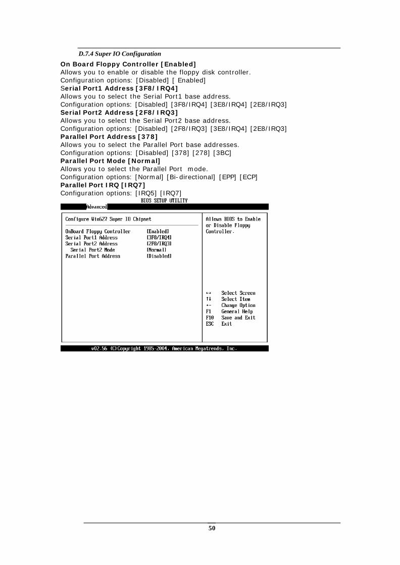
D.7.4 Super IO Configuration
On Board Floppy Controller [Enabled] Allows you to enable or disable the floppy disk controller. Configuration options: [Disabled] [ Enabled] Serial Port1 Address [3F8/IRQ4] Allows you to select the Serial Port1 base address. Configuration options: [Disabled] [3F8/IRQ4] [3E8/IRQ4] [2E8/IRQ3] Serial Port2 Address [2F8/IRQ3] Allows you to select the Serial Port2 base address. Configuration options: [Disabled] [2F8/IRQ3] [3E8/IRQ4] [2E8/IRQ3] Parallel Port Address [378] Allows you to select the Parallel Port base addresses. Configuration options: [Disabled] [378] [278] [3BC] Parallel Port Mode [Normal] Allows you to select the Parallel Port mode. Configuration options: [Normal] [Bi-directional] [EPP] [ECP] Parallel Port IRQ [IRQ7] Configuration options: [IRQ5] [IRQ7]
51
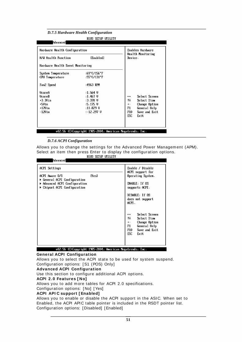
D.7.5 Hardware Health Configuration
D.7.6 ACPI Configuration
Allows you to change the settings for the Advanced Power Management (APM). Select an item then press Enter to display the configuration options.
General ACPI Configuration Allows you to select the ACPI state to be used for system suspend. Configuration options: [S1 (POS) Only] Advanced ACPI Configuration Use this section to configure additional ACPI options. ACPI 2.0 Features [No] Allows you to add more tables for ACPI 2.0 specifications. Configuration options: [No] [Yes] ACPI APIC support [Enabled] Allows you to enable or disable the ACPI support in the ASIC. When set to Enabled, the ACPI APIC table pointer is included in the RSDT pointer list. Configuration options: [Disabled] [Enabled]
52
AMI OEMB table [Enabled] Allows you to enable or disable the inclusion of the BIOS ->AML exchange pointer to (X)RSDT pointer list. Configuration options: [Disabled] [Enabled] Headless mode [Disabled] Enable/Disable headless operation mode through ACPI.
D.7.7 MPS Configuration Configure the Multi-Processor table MPS Revision [1.4] Configuration options: [1.1] [1.4]
D.7.8 Remote Access Configuration Configure Remote Access. Remote Access [Disabled] Configuration options: [Disabled] [Enabled]
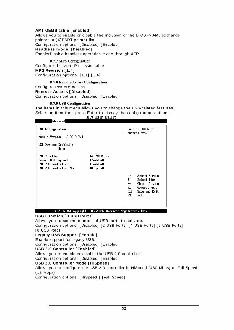
D.7.9 USB Configuration The items in this menu allows you to change the USB-related features. Select an item then press Enter to display the configuration options.
USB Function [8 USB Ports] Allows you to set the number of USB ports to activate. Configuration options: [Disabled] [2 USB Ports] [4 USB Ports] [6 USB Ports] [8 USB Ports] Legacy USB Support [Enable] Enable support for legacy USB. Configuration options: [Disabled] [Enabled] USB 2.0 Controller [Enabled] Allows you to enable or disable the USB 2.0 controller. Configuration options: [Disabled] [Enabled] USB 2.0 Controller Mode [HiSpeed] Allows you to configure the USB 2.0 controller in HiSpeed (480 Mbps) or Full Speed (12 Mbps). Configuration options: [HiSpeed ] [Full Speed]
53
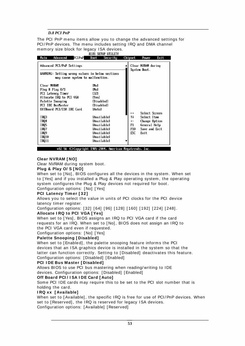
D.8 PCI PnP
The PCI PnP menu items allow you to change the advanced settings for PCI/PnP devices. The menu includes setting IRQ and DMA channel memory size block for legacy ISA devices.
Clear NVRAM [NO] Clear NVRAM during system boot. Plug & Play O/S [NO] When set to [No], BIOS configures all the devices in the system. When set to [Yes] and if you installed a Plug & Play operating system, the operating system configures the Plug & Play devices not required for boot. Configuration options: [No] [Yes] PCI Latency Timer [32] Allows you to select the value in units of PCI clocks for the PCI device latency timer register. Configuration options: [32] [64] [96] [128] [160] [192] [224] [248]. Allocate IRQ to PCI VGA [Yes] When set to [Yes], BIOS assigns an IRQ to PCI VGA card if the card requests for an IRQ. When set to [No], BIOS does not assign an IRQ to the PCI VGA card even if requested. Configuration options: [No] [Yes] Palette Snooping [Disabled] When set to [Enabled], the palette snooping feature informs the PCI devices that an ISA graphics device is installed in the system so that the latter can function correctly. Setting to [Disabled] deactivates this feature. Configuration options: [Disabled] [Enabled] PCI IDE Bus Master [Disabled] Allows BIOS to use PCI bus mastering when reading/writing to IDE devices. Configuration options: [Disabled] [Enabled] Off Board PCI/ISA IDE Card [Auto] Some PCI IDE cards may require this to be set to the PCI slot number that is holding the card. IRQ xx [Available] When set to [Available], the specific IRQ is free for use of PCI/PnP devices. When set to [Reserved], the IRQ is reserved for legacy ISA devices. Configuration options: [Available] [Reserved]
54
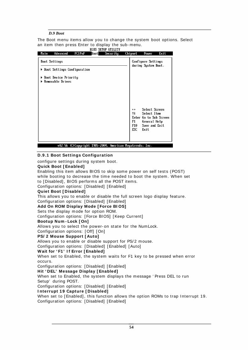
D.9 Boot
The Boot menu items allow you to change the system boot options. Select an item then press Enter to display the sub-menu.
D.9.1 Boot Settings Configuration
configure settings during system boot. Quick Boot [Enabled] Enabling this item allows BIOS to skip some power on self tests (POST) while booting to decrease the time needed to boot the system. When set to [Disabled], BIOS performs all the POST items. Configuration options: [Disabled] [Enabled] Quiet Boot [Disabled] This allows you to enable or disable the full screen logo display feature. Configuration options: [Disabled] [Enabled] Add On ROM Display Mode [Force BIOS] Sets the display mode for option ROM. Configuration options: [Force BIOS] [Keep Current] Bootup Num-Lock [On] Allows you to select the power-on state for the NumLock. Configuration options: [Off] [On] PS/2 Mouse Support [Auto] Allows you to enable or disable support for PS/2 mouse. Configuration options: [Disabled] [Enabled] [Auto] Wait for ‘F1’ If Error [Enabled] When set to Enabled, the system waits for F1 key to be pressed when error occurs. Configuration options: [Disabled] [Enabled] Hit ‘DEL’ Message Display [Enabled] When set to Enabled, the system displays the message ‘Press DEL to run Setup’ during POST. Configuration options: [Disabled] [Enabled] Interrupt 19 Capture [Disabled] When set to [Enabled], this function allows the option ROMs to trap Interrupt 19. Configuration options: [Disabled] [Enabled]
55
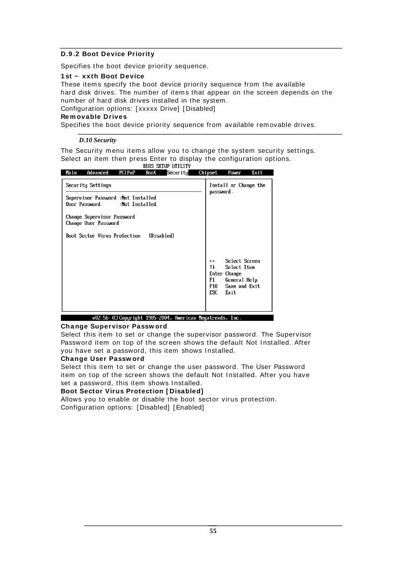
D.9.2 Boot Device Priority
Specifies the boot device priority sequence.
1st ~ xxth Boot Device These items specify the boot device priority sequence from the available hard disk drives. The number of items that appear on the screen depends on the number of hard disk drives installed in the system. Configuration options: [xxxxx Drive] [Disabled] Removable Drives Specifies the boot device priority sequence from available removable drives.
D.10 Security
The Security menu items allow you to change the system security settings. Select an item then press Enter to display the configuration options.
Change Supervisor Password Select this item to set or change the supervisor password. The Supervisor Password item on top of the screen shows the default Not Installed. After you have set a password, this item shows Installed. Change User Password Select this item to set or change the user password. The User Password item on top of the screen shows the default Not Installed. After you have set a password, this item shows Installed. Boot Sector Virus Protection [Disabled] Allows you to enable or disable the boot sector virus protection. Configuration options: [Disabled] [Enabled]
56
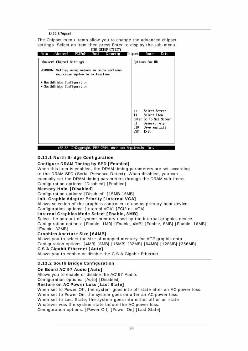
D.11 Chipset
The Chipset menu items allow you to change the advanced chipset settings. Select an item then press Enter to display the sub-menu.
D.11.1 North Bridge Configuration
Configure DRAM Timing by SPD [Enabled] When this item is enabled, the DRAM timing parameters are set according to the DRAM SPD (Serial Presence Detect). When disabled, you can manually set the DRAM timing parameters through the DRAM sub-items. Configuration options: [Disabled] [Enabled] Memory Hole [Disabled] Configuration options: [Disabled] [15MB-16MB] Init. Graphic Adapter Priority [Internal VGA] Allows selection of the graphics controller to use as primary boot device. Configuration options: [Internal VGA] [PCI/Int-VGA] Internal Graphics Mode Select [Enable, 8MB] Select the amount of system memory used by the internal graphics device. Configuration options: [Enable, 1MB] [Enable, 4MB] [Enable, 8MB] [Enable, 16MB] [Enable, 32MB] Graphics Aperture Size [64MB] Allows you to select the size of mapped memory for AGP graphic data. Configuration options: [4MB] [8MB] [16MB] [32MB] [64MB] [128MB] [256MB] C.S.A Gigabit Ethernet [Auto] Allows you to enable or disable the C.S.A Gigabit Ethernet.
D.11.2 South Bridge Configuration
On Board AC’97 Audio [Auto] Allows you to enable or disable the AC’97 Audio. Configuration options: [Auto] [Disabled] Restore on AC Power Loss [Last State] When set to Power Off, the system goes into off state after an AC power loss. When set to Power On, the system goes on after an AC power loss. When set to Last State, the system goes into either off or on state Whatever was the system state before the AC power loss. Configuration options: [Power Off] [Power On] [Last State]
57
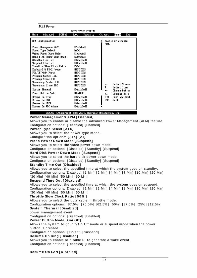
D.12 Power
Power Management/APM [Enabled] Allows you to enable or disable the Advanced Power Management (APM) feature. Configuration options: [Disabled] [Enabled] Power Type Select [ATX] Allows you to select the power type mode. Configuration options: [ATX] [AT] Video Power Down Mode [Suspend] Allows you to select the video power down mode. Configuration options: [Disabled] [Standby] [Suspend] Hard Disk Power Down Mode [Suspend] Allows you to select the hard disk power down mode. Configuration options: [Disabled] [Standby] [Suspend] Standby Time Out [Disabled] Allows you to select the specified time at which the system goes on standby. Configuration options:[Disabled] [1 Min] [2 Min] [4 Min] [8 Min] [10 Min] [20 Min] [30 Min] [40 Min] [50 Min] [60 Min] Suspend Time Out [Disabled] Allows you to select the specified time at which the system goes on suspend. Configuration options:[Disabled] [1 Min] [2 Min] [4 Min] [8 Min] [10 Min] [20 Min] [30 Min] [40 Min] [50 Min] [60 Min] Throttle Slow Clock Ratio [50%] Allows you to select the duty cycle in throttle mode. Configuration options: [87.5%] [75.0%] [62.5%] [50%] [37.5%] [25%] [12.5%] System Thermal [Disabled] power management event. Configuration options: [Disabled] [Enabled] Power Button Mode [On/Off] Allows the system to go into On/Off mode or suspend mode when the power button is pressed. Configuration options: [On/Off] [Suspend] Resume On Ring [Disabled] Allows you to enable or disable RI to generate a wake event. Configuration options: [Disabled] [Enabled] Resume On LAN [Disabled]
58
Allows you to enable or disable LAN GPI to generate a wake event. Configuration options: [Disabled] [Enabled] Resume On PME# [Disabled] Allows you to enable or disable PCI PME# to generate a wake event. Configuration options: [Disabled] [Enabled] Resume On RTC Alarm [Disabled] Allows you to enable or disable RTC to generate a wake event. When this item is set to Enabled, the items RTC Alarm Date, RTC Alarm Hour, RTC Alarm Minute, and RTC Alarm Second appear with set values. Configuration options: [Disabled] [Enabled]
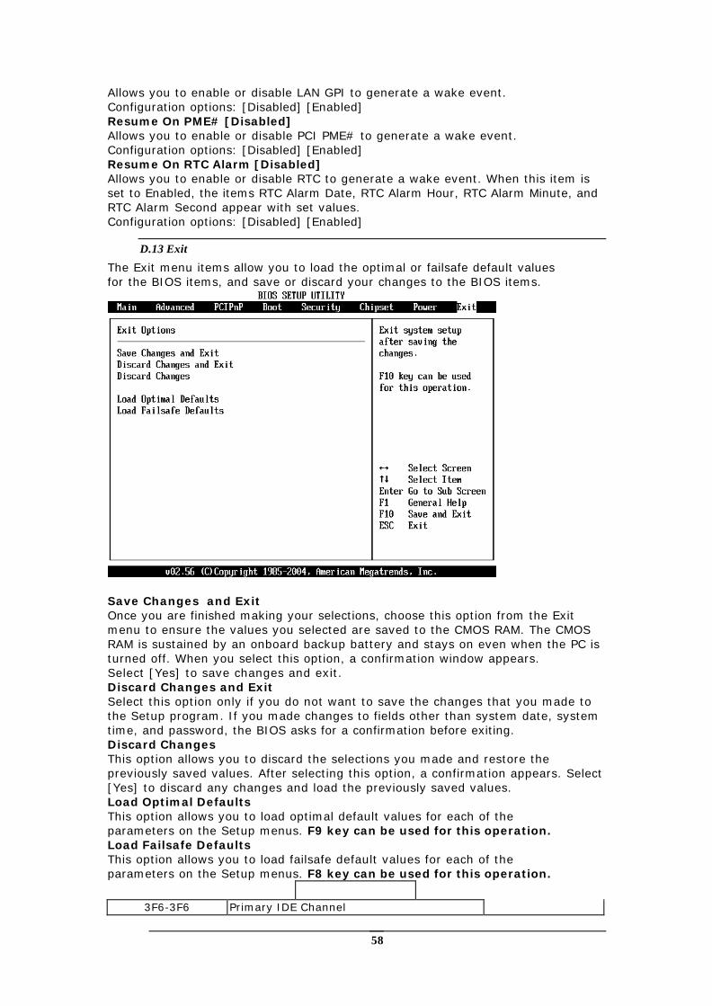
D.13 Exit
The Exit menu items allow you to load the optimal or failsafe default values for the BIOS items, and save or discard your changes to the BIOS items.
Save Changes and Exit Once you are finished making your selections, choose this option from the Exit menu to ensure the values you selected are saved to the CMOS RAM. The CMOS RAM is sustained by an onboard backup battery and stays on even when the PC is turned off. When you select this option, a confirmation window appears. Select [Yes] to save changes and exit. Discard Changes and Exit Select this option only if you do not want to save the changes that you made to the Setup program. If you made changes to fields other than system date, system time, and password, the BIOS asks for a confirmation before exiting. Discard Changes This option allows you to discard the selections you made and restore the previously saved values. After selecting this option, a confirmation appears. Select [Yes] to discard any changes and load the previously saved values. Load Optimal Defaults This option allows you to load optimal default values for each of the parameters on the Setup menus. F9 key can be used for this operation. Load Failsafe Defaults This option allows you to load failsafe default values for each of the parameters on the Setup menus. F8 key can be used for this operation.
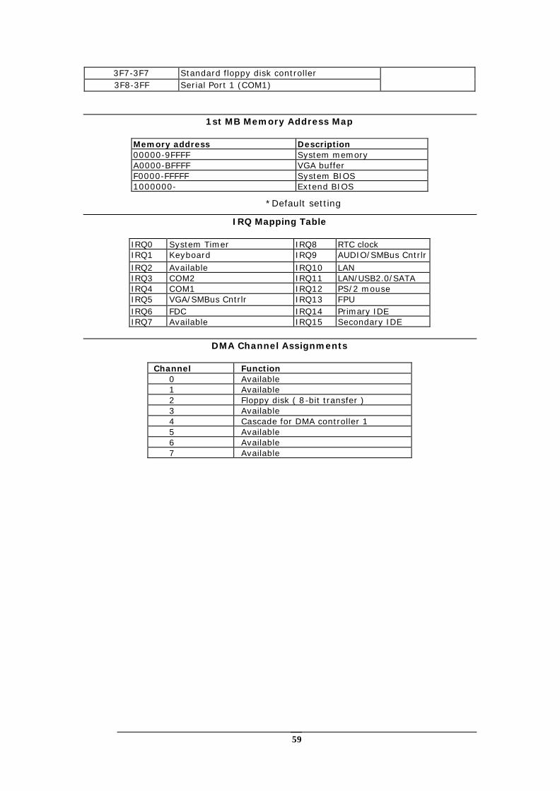
3F6-3F6 Primary IDE Channel
59
3F7-3F7 Standard floppy disk controller 3F8-3FF Serial Port 1 (COM1)
1st MB Memory Address Map
Memory address Description 00000-9FFFF System memory A0000-BFFFF VGA buffer F0000-FFFFF System BIOS 1000000- Extend BIOS
*Default setting
IRQ Mapping Table
IRQ0 System Timer IRQ8 RTC clock IRQ1 Keyboard IRQ9 AUDIO/SMBus Cntrlr IRQ2 Available IRQ10 LAN IRQ3 COM2 IRQ11 LAN/USB2.0/SATA IRQ4 COM1 IRQ12 PS/2 mouse IRQ5 VGA/SMBus Cntrlr IRQ13 FPU IRQ6 FDC IRQ14 Primary IDE IRQ7 Available IRQ15 Secondary IDE
DMA Channel Assignments
Channel Function
0 Available 1 Available 2 Floppy disk ( 8-bit transfer ) 3 Available 4 Cascade for DMA controller 1 5 Available 6 Available 7 Available
60
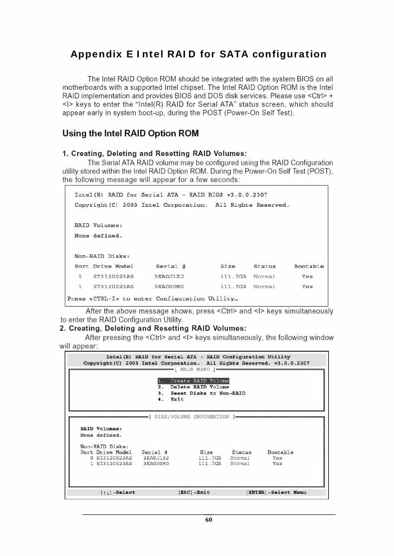
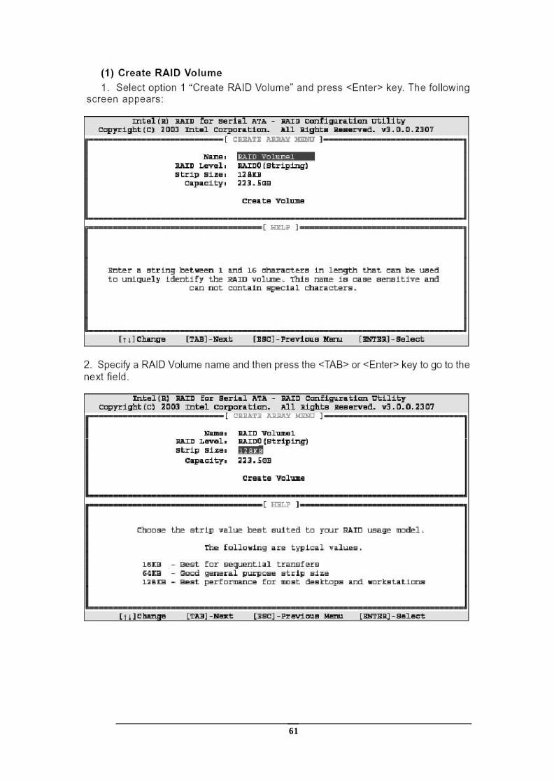
Appendix E Intel RAID for SATA configuration
61
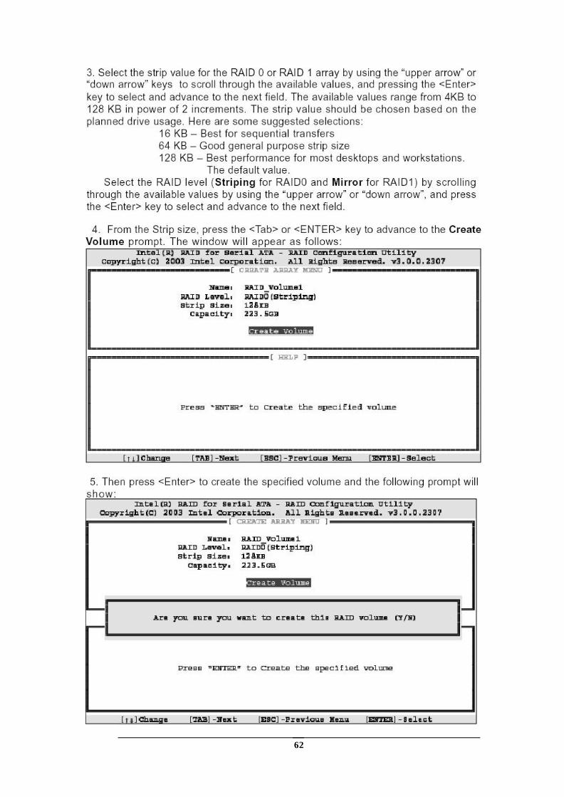
62
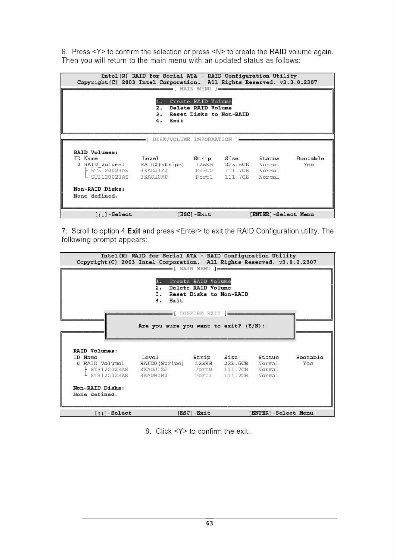
63
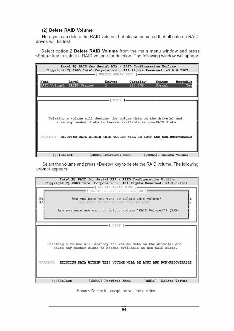
64
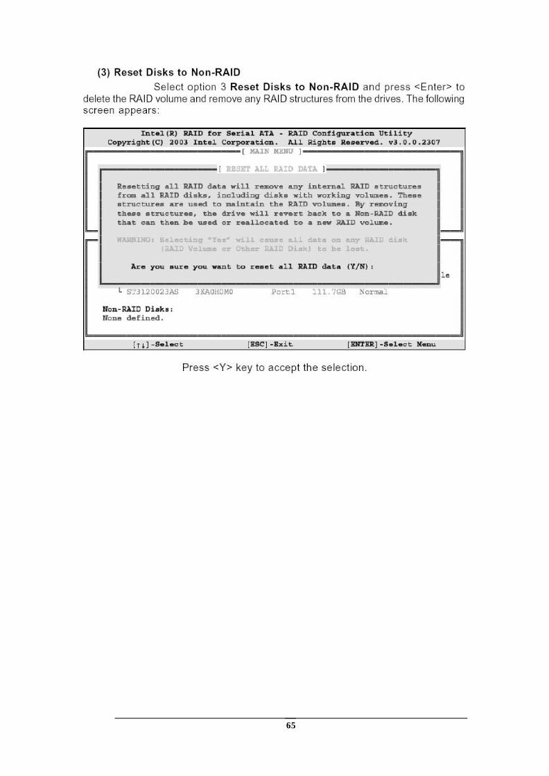
65


![[Eng]Steel Code Check 2011.0 v1](https://static.fdocuments.us/doc/165x107/577cb1691a28aba7118bac20/engsteel-code-check-20110-v1.jpg)


