M f g . C o M p a n y , I Ellis Drill Press Model 9400 · rotation or use the Safety Drill Press...
16
Ellis Drill Press Model 9400 Instruction Manual M FG . C OMPANY , I NC .
-
Upload
hoangkhanh -
Category
Documents
-
view
218 -
download
0
Transcript of M f g . C o M p a n y , I Ellis Drill Press Model 9400 · rotation or use the Safety Drill Press...

Ellis Drill PressModel 9400
Instruction Manual
M f g . C o M p a n y , I n C .

1
POWER FEED DRILL PRESSInfinitely Variable Speed
Model 9400
Operation ManualRevised: Aug. 2016
CONTENTS Page No.Important Information 2Installation Instruction 2Safety Warnings 3Operating Safety & Machine Parameters 4Speed Change / Control Box 4-5Power Train 6Depth of Drilled Hole 6Drill Chuck and Taper Shank Drill Attachment 7Removing Drill Chuck or Drill from Spindle 7Drill Speed and Usage 7Elevating, Rotating and Clamping the Table 7-8Lubrication 8-9Maintenance 9Parts Lists 10-12Trouble Shooting 13Variable Speed Change 14-15
PATENTED
www.EllisSaw.comP.O. Box 930219
Verona, WI 53593-0219Phone: 608-845-6472
Toll Free: 800-383-5547Fax 608-845-5199
M f g . C o M p a n y , I n C .

2
IMPORTANT!!
NOTE: In general, this machine is shipped in the high torque range.
BEFORE USING THIS MACHINE:
• Adjust Range To Meet Your Drilling Needs High torque range preferred for most drilling applications Please call with any questions regarding what range works best for you.
• Read Lubrication Instructions On Page 8This machine is suitable for drilling, reaming or thread cutting in metal, wood or plastic. The reversing feature allows the removal of a thread cutting tap. It is widely used for short part runs or high production. Read the instruction manual carefully for the operation and maintenance of this machine. Keep the machine in a good operational condition and keep it clean. The machine is powered by a 110-Volt single-phase line voltage but the control box (4830) powers a 3-phase, 220-Volt electrical motor at infinitely variable speeds. Some machines are furnished with a control box (4831) for 220 Volt, single phase in and 220 Volt 3-phase out. The control box was programmed at the factory. The program should not be changed by the operator.
INSTALLATION INSTRUCTION
The Ellis Variable Speed Drill Press is crated and shipped completely assembled. Check for any transit damage at the time you accept delivery. Surfaces that are not painted are protected with a film of heavy oil during shipment. Remove this oil after uncrating. It is VERY important to remove this oil from the inside taper bore using mineral spirits or paint thinner by twisting a rag up into the bore.1. After uncrating, place the drill press on a flat, solid floor and within reach of the power cord to a 110-
Volt, 60 HZ Single Phase grounded power outlet. (Some machines are built for 220-Volt single phase.) Make certain that the supply Voltage is 110 Volt (220-Volt). A long extension cord or a low supply Voltage can cause serious problems. The wire connections at the terminals have to be reliably tight.
Donotplugintoapowerreceptacleuntiltherestoftheinstallationisfinished.
WARNING:
Adapters, extension cords and surge protectors should not be used with this product. Also a GFCI (Ground Fault Circuit Interrupter) protected receptacle cannot be used. It is recommended to use a 20 amp, 115-Volt, AC dedicated circuit.2. If the floor is uneven and the drill press rocks, place shims under the base to remove any motion. For
light work the machine can stand on the floor by itself. It is advisable to bolt the machine to the floor when large work pieces are drilled. Four openings are provided in the column base for foundation bolts.
3. For optimum performance the Variable Speed Control assembly is preset at the factory.
Do not tamper with the wiring or settings inside the Variable Speed Control Box or it will void the warranty.

SAFETYDISCONNECT THE POWER CORD FROM THE WALL OUTLET BEFORE ANY MAINTENANCE.
CONTROL BOX AND MOTOR
1. Do not open the Control Box. Tampering with the wiring or setting will void the warranty. The circuit board is not field repairable. Do not touch or adjust anything without calling Ellis Manufacturing Co. for instructions. The circuits in the control box are not isolated. Elements of the circuit board are at 230 Volt. Direct contact with these circuits can cause serious injury.
2. The control circuit is not fail-safe. A disconnect at the wall outlet is the only way to reliably disable the control.3. While power is ON or for some time after power-OFF, do not touch the control box since the control box will
be extremely hot. Doing so can cause burns.
WARNING
• While power is ON or when the control box is running, do not open the front cover. Otherwise you may get an electric shock.
• Do not run the control box with the front cover or wiring cover removed. Otherwise you may access the exposed high voltage terminals or the charging part of the circuitry and get an electric shock.
• Before wiring or inspection, power must be switched OFF. To confirm that, LED indication of the operation panel must be checked. (It must be OFF.) Any person who is involved in wiring or inspection shall wait for at least 10 minutes after the power supply has been switched OFF and check that there are no residual voltage using a tester or the like. The capacitor is charged with high voltage for some time after power OFF, and it is dangerous.
• This control box must be earthed (grounded). Earthing (grounding) must conform to the requirements of national and local safety regulations and electrical code (NEC section 250, IEC 536 class 1 and other applicable standards). A neutral-point earthed (grounded) power supply for 400V class control box in compliance with EN standard must be used.
• Any person who is involved in wiring or inspection of this equipment must be fully competent to do the work.• Setting dial and key operations must be performed with dry hands to prevent an electric shock. • Do not subject the cables to scratches, excessive stress, heavy loads or pinching. Otherwise you may get
an electric shock.• Do not change the cooling fan while power is ON. It is dangerous to change the cooling fan while power is
ON. • Do not touch the printed circuit board with wet hands. Otherwise you may get an electric shock.
3

OPERATING SAFETY
1. Always wear safety glasses2. Do not wear gloves, necktie, loose clothing, jewelry or other items that may get caught in moving parts. Long hair should be tied up and under a cap.3. Do not hold the part to be drilled by hand. Clamp the work or brace it against the drill press column to prevent
rotation or use the Safety Drill Press Vise; see the enclosed installation sheet about the Safety Drill Press Vise. Two T-Slots are provided in the table and column base to aid clamping.
4. Use recommended speeds that are proper for the drill, the material being drilled and accessories used.5. Make a habit of removing the chuck key, drift key and other wrenches after their use.6. Keep hands and fingers clear of the drill bit or cutter.7. Shut off the power before removing the drill bit or cutting tool.8. Do not try cutting or similar operations by moving the table or the head stock with respect to each other. Be
sure that the head stock and table are securely clamped to the column.9. Be sure the drill bit or cutting tool is securely clamped in the chuck.10. Keep belt guard in place and closed.11. Do not operate the machine beyond its capacity and possibly overload the power train.12. Maintain the machine regularly, keep it clean and keep a maintenance and lubrication log.
SPEED CHANGE
A quick Speed (Torque) Range change can be accomplished with the Ellis HI-Lo Handle on the right side of the machine. (See page 14.) Note: The motor must rotate at a moderate speed to change the operating speed range selection. The variable speed control can vary the speed infinitely within each speed (Torque) range setting which is explained in the next paragraph.
LOW SPEED HIGH TORQUE OPERATION
It is highly recommended to shift into low using the “Ellis High/Low shift.” For larger diameter drills, tapping and hole saws, see pages 14 and 15 for more information.
4
Motor
MACHINE PARAMETERS
Maximum drill diameter 1.062" steel; 1.25" cast ironTapping capacity 3/4"-10 NCMaximum spindle travel 5.38"Spindle inner taper Morse #3Spindle speed Variable, 0-1200 rpmSize of table 15.88" x 17.88" or 16.50" Dia.Size of base 16.38" x 26.62"Power feed rate per spindle revolution .004"Diameter of column 4.0"Recessed diameter of quill 3.0"Exposed diameter of quill 3.75"Spindle travel 5.75"Spindle to table 27.25"Maximum distance spindle nose to base surface 46.25"Drills to center 18.12"Motor 2 HPNet weight 675 LBOverall size 20"W x 29"D x 69.5"H
DO NOT WEAR JEWELRY, LOOSE CLOTHING
OR LONG HAIRWHEN OPERATING THIS EQUIPMENT

5
ELECTRICAL CONTROL BOX
Set upDO NOT PLUG INTO A GFI CIRCUIT.Start Turn the BIG RED EMERGENCY button clockwise (in the direction of the arrows) so that the button will pop out and the read out window will light up. Turn the Forward/Reverse switch to the reset position then to the desired direction of forward or reverse.
Set Button The small (middle) white SET button changes the read-out display in the number window. When the letter “A” lights up beside the window it shows the ampere draw of the motor. The voltage is shown when there is no letter on display.
Speed Push the small white SET button until you see the letters “HZ”. Now the read-out window displays the frequency in cycles/seconds. That feature controls the speed of the motor. This is NOT the RPM of the spindle but represents a reference that is relative to the spindle speed. (120 HZ = 100% of the spindle speed)
Speed Change The BLACK button in the upper left hand corner regulates the spindle speed. It works in both the forward and reverse mode. Spinning the black knob in the upper left corner regulates the spindle speed. A clockwise rotation of the knob increases spindle speed in both the forward and reverse directions.
Forward Toggle Switch Position (4767) Use the Forward Switch Position for standard drilling, tapping and hole saw cutting.
Reverse Toggle Switch Position (4767) Use the Reverse Switch Position to retract a tap or to tap a left hand thread. Keep downward pressure on the feed handle when backing a tap out of the work piece.
Stop/Reset Toggle Switch Position (4767) This setting stops the motor from either forward or reverse rotation. Use this as the STOP switch while operating the drill press. Reset to the position after a power outage or after hitting the BIG RED EMERGENCY BUTTON (4819).
Stop The BIG RED button stops the machine and automatically disconnects the machine from electrical power after a time delay of about twenty seconds. Use this as the Power Off switch at the end of the work day.
Note: Avoid stalling the spindle and stopping the motor under power; the resulting current surge can damage the electronic components in the control box. Turn Power off immediately in a stalled motor condition. Clear the jam mechanically. Repeated stalling abuse is detectable and can lead to voiding the warranty.
4767 4819Toggle Switch

6
POWER TRAIN
Spindle SpeedThe motor drives the middle pulley and the spindle pulley by a V-Belt. The spindle pulley drives the spindle and the taper sleeve. The spindle speed is variable by means of the variable speed control box or with Ellis Hi-Lo handle. Forward and reverse rotation of the spindle is selected on the control box panel. If you have any problems with this, call the factory.
Power Feed and Manual FeedSpindle feed can be accomplished in two modes: manual and by power. Manual Feed is accomplished by turning the turn style (8474) at the right side of the head stock. Pulling any of the two turn styles to the right engages the power feed and returning it to the left stops the power feed. The thumbscrew (7027) must be loosened to engage the power feed, and tightening this thumbscrew prevents the machine from actually engaging in the power mode. Use the power feed only when the spindle rotates in the CW (clockwise) rotation. Do not use power feed in the tapping mode.
DEPTH OF DRILLED HOLEDo not use the depth dial for through holes: unlock the locking clamp on the face of the depth dial.Proceed as described in the following for drilling holes to preset depth:1. Stop the spindle rotation. Loosen the locking handle on the depth scale hub. Lower the drill end to
the desired drill depth by turning the turn style. Turn the dial CCW (counter clockwise) as you face the end of the turn style hub. Lock the locking clamp when the dial comes to a stop.
2. Note: When drilling through holes, place a block of wood or scrap piece of metal under the work piece to prevent drilling into the table or use an Ellis Safety Drill Press Vise.
3. The machine is equipped with a power feed overload clutch. The overload clutch protects the feed power train from damage if too high a feed rate or too high a spindle speed is used. The overload clutch disengages when you hear a clicking noise. Reduce the feed rate or spindle speed when this occurs. The overload torque at which the clutch disengages can be increased by turning the adjustment screws clockwise and can be decreased by turning the adjustments screw counterclockwise. There are two adjustment screws in the pulley groove at 180 degree from one another.
Note: Do not tighten the screws too far because a solid spring cannot let the ball escape from the groove in the shaft. In this case the overload clutch would be rendered useless and damage can occur. To set the maximum torque: turn each set screw until tight and then back them out by two.

DRILL CHUCK AND TAPER SHANK DRILL ATTACHMENT
The size of the taper to be used with this machine is a Morse # 3 Taper. It is important to wipe the inside taper in the spindle and the outside of the chuck taper or drill taper clean of oil or dirt. Insert the arbor into the spindle and twist to align the tang with the slot in the spindle then thrust upward sharply to seat the chuck. Follow the same procedure for a taper shank drill or accessory. A wood hammer can assist in doing this.
REMOVING DRILL CHUCK OR DRILL FROM SPINDLE Loosen the locking handle on the depth scale collar. Lower the quill until the slot is completely uncovered. Grasp the locking handle and turn the collar CW (clockwise) as you face the end of the style handle body. Lock the handle securely when the collar comes against a stop. Turn the spindle until its slot lines up with the one in the quill. Insert the drift key into the slot. Hold the chuck or drill with one hand while tapping on the drift key with a hammer.
DRILL SPEEDS AND USAGEThe speed at which the drill has to rotate for efficient cutting depends on the type of material being worked and the diameter of the drill. Use a squirt bottle to add cutting oil (fluid) to the drill. Retract the drill often when deep holes are drilled; this removes chips. Use a low Spindle Speed (Torque) for tapping a threaded hole. Use a heavy oil or thread cutting fluid to lubricate the tap. Reverse the spindle rotation with the reverse switch on the variable speed control panel to retract the tap.
ELEVATING, ROTATING AND CLAMPING THE TABLEThe table can rotate 360 degrees and move up and down on the column. Loosen both clamp screws, rotate the table in the required position, elevate the table by means of the elevation handle and tighten both clamp screws again.
7
QUILLSLOT
DRIFTKEY
CHUCK

LUBRICATIONThe power feed gear box at the right side of the head stock has a grease nipple. Another grease nipple is at the left side near the sight window, see next page.
LUBRICATION SCHEDULE
Location Suggested Lubricant FrequencyGrease Nipple Lithium Grease N.L.G.I. # 2 Daily or twice daily under heavy use
Under light use, grease at least every other day. It is much more important that you grease the machine frequently than to worry about the type of lubricant used. Do not mix synthetic and mineral base oils.
8

MaintenanceKeep table and sliding parts clean of dirt and chips. Every 3 months lower the quill, wipe clean and oil lightly. If raising the table becomes difficult, clean and wipe the column with light machine oil. The ball bearings in the motor, quill and V-Belt pulleys are lubricated for life. Keep the cooling fins of the speed control box and the motor clean and free of dirt and dust.
The chart below identifies the bearings in the various locations. The Ellis Part Number is required for replacement orders.
No. Bearing Type Location Part No. Size Qty. 1 Deep Groove Spline-Taper Sleeve 4490 45 x 75 x 16 2 2 Deep Groove Quill 4491 30 x 55 x 13 1 3 Ball Thrust Quill 4492 35 x 52 x 12 1 4 Deep Groove Quill 4493 35 x 72 x 17 1 5 Deep Groove Middle Sheave 4494 17 x 40 x 12 2 6 Deep Groove Single Thread Worm 4495 20 x 42 x 12 1 7 Deep Groove Single Thread Worm 4495 20 x 42 x 12 1
9
1
2
3
4
6
7
5
Spindle

10
PARTS LIST Table & Base Assembly Drill Press 9400
8 4 8 6
8 4 0 9
8 4 1 0
8 4 4 3
8 4 4 2
8 4 0 7
8 4 0 4
8 4 0 3
8 4 0 1
8 4 0 2
8 0 7 7
8 4 0 5
8 4 0 6

4058 Hex Head Cap Screw4144 Set Screw4146 Socket Set Screw4260 Hex Nut4346 Lock Washer4487 Ball Bearing (15 x 32 x 9)4530 Knob4831 Control Box, 230 Volt4646 HiLo Pulley4647 Motor4830 Control Box, 115 Volt4938 V-Belt-Upper, Power Feed4939 V-Belt-Lower, Front Drive4943 V-Belt, Rear Drive5059 Label7027 Thumb Screw8077 Ring8081 Set Screw8104 Range Position Bolt8107 Range Position Tube8115 Shift Handle8127 Control Box Mount Plate8401 Base8402 Column Collar8403 Rack8404 Column8405 Gear8406 Elevating Handle8407 Clamp Screw8409 Worm8410 Square Table8411 Spindle8412 Nut8413 Thrust Plate8414 Worm Cover8415 Quill8416 Counter Block8417 Worm, single thread8418 Shaft8419 Head Stock8423 Spring Cap8429 Spiral Spring and Cover Assembly
8430 Spacer8431 Cover8432 Spindle Shaft8433 Worm Base8434 Spindle Pulley8435 Overload Compression Spring8436 Nut8437 Feed Pulley8438 Overload Cover8439 Handle Hub8440 Dial8441 Key8442 Table Bracket8443 Clamp Screw8445 Pin, Spring8446 Pin, Pawl8447 Middle Sheave8449 Middle Sheave Spacer8452 Worm Cover8453 Worm, Double Thread8454 Shim Plate8455 Gear8457 Transmission Shaft8458 Gear8459 Base8460 Hub8461 Bevel Gear8462 Pawl8464 Spring8465 Plate8466 Feed Box8467 Block8468 Feed Label, Power8469 Feed Label, Manual8470 Worm Housing8471 Lock Screw8472 Lock Handle8473 Washer8474 Handlebar8476 Swivel Base8481 Handle Grip8486 Revolving Handle
Part No. Name Part No. Name
PARTS LIST 9400 Drill Press
11

12
8438843749388436
8435
8434
8433
8432
8431
8430
842984238422
8426
8154
48304831
505984288427
8419
8418
(115 V)(220 V)
84168415
841484138412
8411
Bearings are identified in the manual
4146,8440
7027, 42608439
84588417
846084468445
8441
4487
PATENTED
4487
8104453041448107
40584346
4939
8447
8476
8449
464680814943
4647
8475
8115
8452
4487
845384548455
8457
84594487
8461846284638464
84668465
8467
84698468
8470
8472
8474
8473
8471
8481
PARTS LIST Head Assembly 9400 Drill Press
8461

Problem Probable Cause RemedyMotor Does Not Run Power cord not plugged into source Plug into receptacle
Power not “ON” at Speed Control Box Push “RUN” Button
Speed knob in “0” position Turn knob CW for more speed
Motor too hot, heat switch tripped Wait for motor to cool off
Power cord plugged into GFCI protected outlet
Plug into an unprotected outlet preferably a dedicated circuit of 20 amp, 115 VAC
Power cord not plugged into correct outlet Power cord of a 115 V single phase machine has to be plugged into a 115 V outlet. A cord of a 230 single phase machine has to be plugged into a 230 V outlet.
Noisy Operation Incorrect belt tension Adjust tension
Loose spindle or motor pulley Tighten set screw
Belt is too tight Reduce belt tension
Spindle bearing worn Replace spindle ball bearing
Spindle Not Moving Up Return spring may be broken Replace spiral spring
Drill Bit Smokes Or Is Burnt Incorrect speed Change speed
Chips are not coming out of hole Retract bit frequently to clear out chips
Dull drill bit Sharpen or replace drill bit
Feed too slow Increase feed to allow bit to cut
Needs lubrication Lubricate with cutting fluid
Drill is running in reverse Change motor rotation
Excessive Drill Run Out Bent drill Replace drill
Chuck jaws not clamping evenly Install drill correctly
Worn spindle bearings Replace ball bearings
No Power Feed Worm gear worn Replace worm gear
Overload protection device not working Tighten springs with set screws
Pawl clutch is worn Replace pawls
Feed belt is sliding Tighten belt
Turn style does not move sideways Loosen thumb screw #7027
Hole Depth Not Correct Depth dial not clamped Tighten dial lock
Worm gear or quill worn Replace gear
Drill Not Rotating Taper on chuck slips in spindle Remove grease and oil from inside taper bore in spindle and outside of taper on chuck. Use mineral spirits.
Spindle Not Rotating In Correct Rotation
Switch on control box may not be in correct position
Use forward switch for standard drilling and cutting. Use reverse switch to retract a tap or tapping for left-hand threads.
13
TROUBLESHOOTING
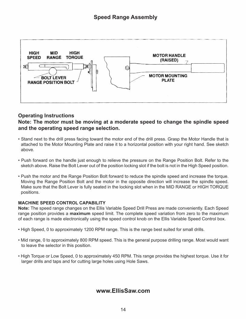
Operating InstructionsNote: The motor must be moving at a moderate speed to change the spindle speed and the operating speed range selection.
• Stand next to the drill press facing toward the motor end of the drill press. Grasp the Motor Handle that is attached to the Motor Mounting Plate and raise it to a horizontal position with your right hand. See sketch above.
• Push forward on the handle just enough to relieve the pressure on the Range Position Bolt. Refer to the sketch above. Raise the Bolt Lever out of the position locking slot if the bolt is not in the High Speed position.
• Push the motor and the Range Position Bolt forward to reduce the spindle speed and increase the torque. Moving the Range Position Bolt and the motor in the opposite direction will increase the spindle speed. Make sure that the Bolt Lever is fully seated in the locking slot when in the MID RANGE or HIGH TORQUE positions.
MACHINE SPEED CONTROL CAPABILITYNote: The speed range changes on the Ellis Variable Speed Drill Press are made conveniently. Each Speed range position provides a maximum speed limit. The complete speed variation from zero to the maximum of each range is made electronically using the speed control knob on the Ellis Variable Speed Control box.
• High Speed, 0 to approximately 1200 RPM range. This is the range best suited for small drills.
• Mid range, 0 to approximately 800 RPM speed. This is the general purpose drilling range. Most would want to leave the selector in this position.
• High Torque or Low Speed, 0 to approximately 450 RPM. This range provides the highest torque. Use it for larger drills and taps and for cutting large holes using Hole Saws.
www.EllisSaw.com
14
Speed Range Assembly

MODEL 9400ELLIS VARIABLE SPEED DRILL PRESSWITH QUICK SPEED RANGE CHANGE
EllisMfg.Company,Inc.•POBox930219•Verona,WI53593-0219•1-800-383-5547
15
www.EllisSaw.com
M f g . C o M p a n y , I n C .