M E T ROVER MSCD Engineering Technology Critical Design Review Metropolitan State College of Denver...
36
M E T ROVER MSCD Engineering Technology Critical Design Review Metropolitan State College of Denver April 2004
-
Upload
amberly-hubbard -
Category
Documents
-
view
214 -
download
0
Transcript of M E T ROVER MSCD Engineering Technology Critical Design Review Metropolitan State College of Denver...
M E T ROVER
MSCD Engineering Technology
Critical Design Review
Metropolitan State College of Denver
April 2004

Mission Description
Deploy rover from the payloadcarrier upon landing.
Image flight and landing site autonomously.
Accomplish mission under strictmass limitations.
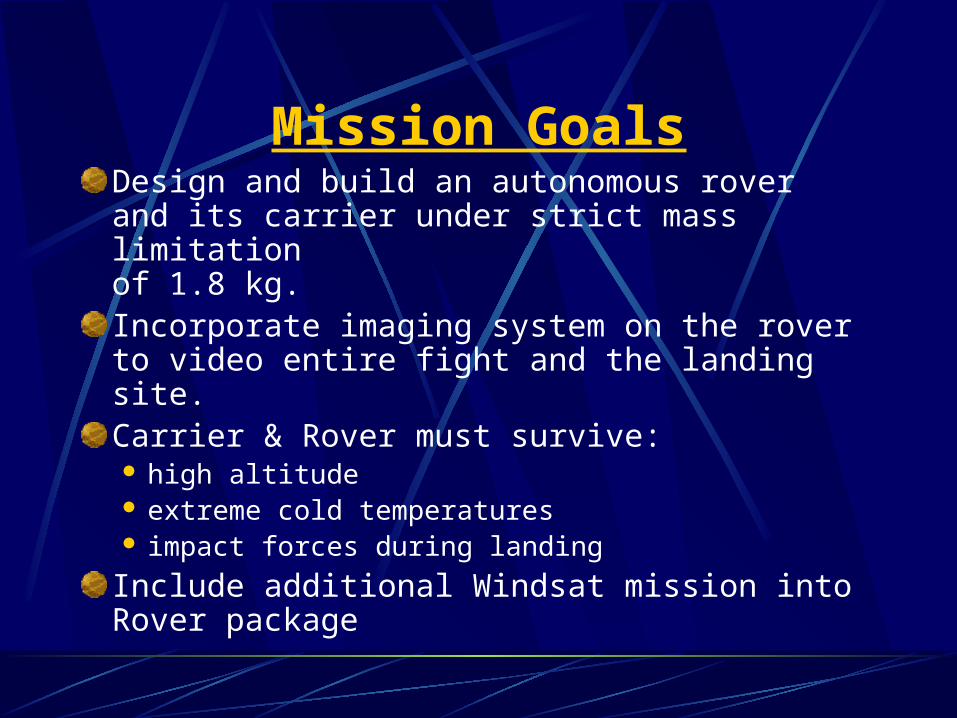
Mission GoalsDesign and build an autonomous roverand its carrier under strict mass limitation of 1.8 kg.Incorporate imaging system on the rover to video entire fight and the landing site.Carrier & Rover must survive: high altitude extreme cold temperatures impact forces during landing
Include additional Windsat mission into Rover package

NASA Benefits
Prototype development which maybe used during future missions toMars or the moon.
Test existing paradigms of rover design.
Explore new methods of rover design, construction, and deployment.

Project Requirements
Carrier and Rover combined must meet 1.8 kg mass limitation.
Rover must image the landing site.
Rover must deploy at the landing site.
Rover must have a drive systemallowing it to maneuver on the groundat the landing site.

Mass Budget
Carrier 400g
Camera (w/out battery) 166g
Drive motor/gearbox assembly 200g
Chassis & Electronics 400g
Wheels 400g
WindSat addition 234g
Total 1800g

Rover Design
Must operate in either orientation.
Drive arms move to raise chassis height.
Each wheel has independent motor.
Chassis made of carbon fiber composite.
Electronics will be insulated inside chassis.

Rover Design

Rover Design

Wheel Design

Rover Drive System
Drive the Rover out of the carrier and around the landing site.
One electric motor per wheel to get four wheel drive and steering.
Operate the rover in either of twopossible carrier landing orientations.
Incorporate obstacle avoidance system.

Drive Components
Orientation sensor.
Drive motors inside each wheel.
Movable side arms to raise chassis height.
Obstacle avoidance system.
Drive wheels.

Drive System InterfacesOrientation
SensorObstacleSensor
Controller
DriveArms
Motors

Drive System Prototyping
Aluminum wheels:Machined from solid 4.25 inch diameter
aluminum bar stock.Goal weight (mass) of 100 grams per
wheel.Drive arms machined from ¼” x ¾” stock.

Carrier System
Securely carry the Rover payload to high altitude and back.
Constructed foam and carbon fiber composite.
Open to allow the deployment of the Rover upon landing in correct orientation.

Carrier Components
Air piston system to open carrier
Foam-core with carbon fiber Carrier.
Rover door latching mechanism.
Rover opening mechanism.

Carrier Design
Imaging System
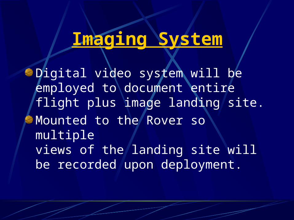
Digital video system will be employed to document entire flight plus image landing site.
Mounted to the Rover so multipleviews of the landing site will be recorded upon deployment.

Imaging Components
Panasonic SD mini digital video camera.
MPEG4 video compression.
Over 2 hr. 20 Min. of recording time.
320x240 dot/ 420 Kbps.
512 MB memory card.
Solar power unit to power video camera.

Electrical Requirements
Control and operate the Imaging & Drive Systems.
Open the Rover carrier upon landing.
Orientate the Rover and chassis.
Direct rover around obstacles.
Process and store in flight data.
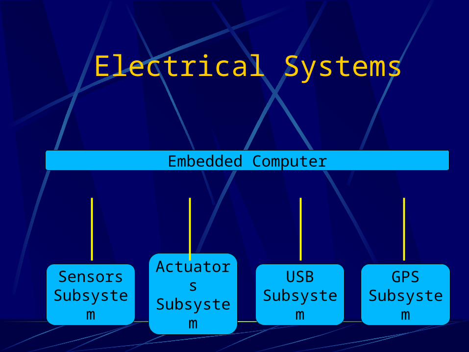
Electrical Systems
Embedded Computer
SensorsSubsystem
ActuatorsSubsystem
USBSubsystem
GPSSubsystem
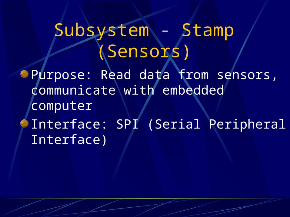
Subsystem - Stamp (Sensors)
Purpose: Read data from sensors, communicate with embedded computer
Interface: SPI (Serial Peripheral Interface)

Subsystem - Stamp (Sensors)
Altimeters
Temp Sensors
Tilt Sensors
Digital Compass
Wheel Encoders
Arm Angle Encoders
BASICSTAMP IIControllers
SPIInterfaceEmbedded
Computer

Subsystem - Stamp (Actuators)
Purpose: Control actuators, communicate with embedded computer
Interface: SPI (Serial Peripheral Interface)

Subsystem - Stamp (Actuators)
BASICSTAMP IIControllers
SPIInterfaceEmbedded
Computer
ParallaxServo
Controller
PololuMotor
Controllers
Relays
LCD
Motors
Servos

Subsystem – USB
Purpose: Provide communication between embedded computer and USB Devices
Interface: System Bus

Subsystem – USB
TD OT243USBHost
Controller
System BusInterfaceEmbedded
Computer
Flash Memory
Hub
HubCamera 3
Camera 2
Camera 1

Subsystem – GPS
Purpose: receive GPS signals and communicate coordinates to embedded computer
Interface: RS232 Serial

Subsystem – GPS
GaminGPSOEM
RS232 SerialInterfaceEmbedded
ComputerAntenna

Power Budget (incomplete)Component Voltage Current Power Time Total Power
Coldfire 3.3v ~250mA ~850mW 3hr 2550mWhStamps 5v 16mA 80mW 3hr 240mWhLaser 5v 65mA 325mW 0.1hr 33mWhTD243 USB 3.3v 12mA 40mW 3hr 120mWhGPS 5v 85mA 425mW 3hr 1275mWhMotorsServosUSB Cams
Total

Budget (Electronics/Software)Item(s) Status Price
Arcturus Networks Coldfire 5272 uCdimm dev kit Have it 1200Parallax Stamp BS2's and dev kits Have it 2451mW Laser, single line head, bandpass filter Have it 424Lynxmotion servo pan/tilt kit Have it 60Parallax servo contoller Have it 39Stamp AppMod Digital Compass Have it 59TrendNet TV-PC301 USB Cams (OV511+, OV7620) Ordered 132DS1620 Digital Thermometers Have it NCMemsic 2125 accelerometer/tilt sensor Have it NCPololu micro dual motor controllers Have it NCReed relays, switching transistors, resistors Have it NCLCD 2x16 Serial 50Garmin OEM GPS, Antenna ~175Transdimension EVB243, host controller software ~500USB Compact Flash Reader, 128Mb Compact Flash, USB Hubs ~165

Prototyping (Electronics/Software)
Set up development computer with compiler, dev tools, NFS. Ran simple program on embedded computer to flash LED's
Tested various USB cams and software
Experiences/Hardware from last year

Electronics Components
Altitude sensor.
Rover orientation sensor.
Obstacle avoidance sensor.
Micro-controller.
Wiring to/from sensors, camera and drive motors.
Carrier door latch servo.
Onboard programming.

Project OrganizationProfessor
KeithNorwood
Don GrissomTeam Lead
Power OscarMatt
LukeNathanChris
Amparo
ImagingBrianDon
Chris
CarrierOscarLeah
WalterJohn
Electronics Luke
NathanAmparo
Chassis John WalterMattLeahBrianDon

BudgetExpenses to date:
Beginning total $4000Carbon fiber materials $ 150Camera $ 800Motors/gearbox assy. $ 40Wheel material $ 100Machining tools $ 50Carrier material $ 30Misc. Material and Electronics $1800subtotal $2970
Remaining Balance $1030

Schedule
Construction Completed June 15
Operational testing Completed July 20
Final Construction Completed July 30
Mission Readiness Review July 30
Launch Readiness Review Aug 6
Launch Aug 7


![Instructables.com - Land Rover Discovery 3 Range Rover ......Land Rover Discovery 3 MK III [2004-2009] 2.7 (Diesel) TDV6 Land Rover Range Rover Sport [2005-2013] 2.7 (Diesel) TDV6](https://static.fdocuments.us/doc/165x107/6107e8324018d80518797305/-land-rover-discovery-3-range-rover-land-rover-discovery-3-mk-iii-2004-2009.jpg)