M DOT PAVEMENT DESIGN MANUAL 4.pdfMnDOT Pavement Design ... • If there is a definite change in the...
44
MnDOT Pavement Design Manual, April 10, 2018 MNDOT PAVEMENT DESIGN MANUAL Chapter 4 – HMA (Hot-Mix Asphalt) MnDOT Pavement Engineer Date
Transcript of M DOT PAVEMENT DESIGN MANUAL 4.pdfMnDOT Pavement Design ... • If there is a definite change in the...
MnDOT Pavement Design Manual, April 10, 2018
MNDOT PAVEMENT DESIGN MANUAL
Chapter 4 – HMA (Hot-Mix Asphalt)
MnDOT Pavement Engineer Date
MnDOT Pavement Design Manual, April 10, 2018
Contents Introduction ........................................................................................................................................................ 1
400 – New/Reconstructed HMA Pavements................................................................................................ 2
410 - Reclamation/Recycling of Existing HMA Pavement ......................................................................... 4
420 – Rubblization and Crack and Seat ........................................................................................................ 12
430 - Pavement Design using MnPAVE-Flexible ...................................................................................... 15
440 - HMA Overlay of Existing Pavement .................................................................................................. 30
450 - Materials and Specifications ................................................................................................................. 34
MnDOT Pavement Design Manual, April 10, 2018
1
Introduction
For this manual, HMA refers to hot-mix asphalt or warm-mix asphalt layers of a pavement structure.
HMA pavement may be constructed on new aggregate base, recycled material used as aggregate
base, such as full-depth reclamation (FDR), or placed as an overlay on existing pavement. Other
asphalt containing materials such as cold in-place recycling (CIR) or stabilized full-depth reclamation
(SFDR) is considered as stabilized aggregate base material. Surface treatments, such as seal coats or
microsurfacing, are considered as surface treatments and not pavement.
This chapter contains directions for designing HMA pavement on mainline highways, determining
the HMA specification required for a Materials Design Recommendation (MDR), and evaluating
existing pavement with regard to rehabilitation with a HMA overlay. The process for pavement-type
selection is contained in Chapter 7 – Pavement-Type Selection.
MnDOT Pavement Design Manual, April 10, 2018
2
400 – New/Reconstructed HMA Pavements
This section contains directions to design pavements for projects that include the complete removal
of the existing pavement or construction on a new alignment.
New/reconstructed HMA pavements are built on aggregate base and granular subbase. The base
and subgrade provide a portion of the pavement’s structure, a solid working platform for
construction and improved engineering properties as compared to native, non-granular soils; such as
higher strength, less reduction in strength during spring thaw, lower frost susceptibility, and
improved drainage.
Use the following standards to design new/reconstructed HMA pavements:
1. Projects that involve working the existing soil must comply with Figure 400.1 and its notes.
2. Projects that do not involve working the existing soil must comply with the following:
A. These projects must have existing soil, subbase, and/or aggregate base material in good
condition, suitable to perform as a portion of the pavement structure and to remain in the
pavement section. The designer must evaluate the existing materials and determine what
material will remain and what treatment, if any, will be required.
B. These projects do not need to comply with all of the requirements shown in Figure 400.1.
However, a minimum of 4.0 inches of HMA (a 5.0-inch HMA minimum may be used on
urban sections) on a minimum of 6.0 inches of aggregate base must be used.
3. Design the pavement using MnPAVE-Flexible according to Section 430 –
Pavement Design Using MnPAVE-Flexible.
4. Specify the mix type, ride specification, lift thicknesses, and compaction requirement using
Section 450 – Materials and Specification.
5. Any construction beneath the typical shown in Figure 400.1 is at the discretion of the District
Materials/Soils Engineer. For guidance regarding the pavement subsurface design see Chapter 3
- Pavement Subsurface.
6. For guidance on pavement cross sections consult the MnDOT Road Design Manual (Chapter
4 –Cross Sections and Chapter 7 – Pavement Design).
MnDOT Pavement Design Manual, April 10, 2018
3
Figure 400.1 – Pavement design standards for new/reconstructed HMA pavement for projects that
involve working the existing soil.
NOTE 1 For non-granular soils, the minimum pavement structure (i.e. pavement, aggregate
base, and subbase) thickness required is:
30.0 inches for 20-year BESALs ≤ 7 million
36.0 inches for 20-year BESALs > 7 million
NOTE 2 Any construction beneath the typicals shown above shall be at the discretion of the
District Materials/Soils Engineer.
4.0-inch minimum thickness
5.0-inch HMA minimum may be used on
urban sections
6.0-inch minimum thickness
For non-granular soils use select granular.
Class 3 or class 4 can be substituted for a
portion of the select granular material at
the discretion of the District Materials/Soils
Engineer.
For granular soils (percent passing ratio
[no. 200 (75 μm)/1.0 inch (25 mm)] sieve ≤
20), mix and compact the upper 12.0 inches
(minimum) of the existing granular soils.
See Note 2
MnDOT Pavement Design Manual, April 10, 2018
4
410 - Reclamation/Recycling of HMA Pavement
Reclamation/Recycling of HMA pavement includes processes that grind the existing HMA
pavement and re-use it in the new pavement section. This includes full-depth reclamation (FDR),
stabilized full-depth reclamation (SFDR), cold in-place recycling (CIR), and cold central plant
recycling (CCPR). For more information see the Basic Asphalt Recycling Manual from the Asphalt
Recycling and Reclaiming Association which may be obtained at the following link https://arra.site-
ym.com/store/ListProducts.aspx?catid=595203.
If the existing HMA material is removed from the roadway and then re-used as base, then use Section 400 – New/Reconstructed HMA Pavements.
1. Pavement condition assessment
Assess current pavement condition and existing materials.
A. Examine existing pavement to determine whether there are weak subgrade or base areas.
B. Use Ground Penetrating Radar (GPR), to ascertain pavement and base thicknesses.
C. Take cores samples for calibration purposes of the GPR and for evaluation of the HMA. The
total number of cores should equal at least one per quarter mile.
D. Analyze cores to discern the uniformity of gradation, crushing, and condition. Evaluate the
sample’s gradation and crushing along discontinuities by slicing the core, performing a burn
extraction and analyzing the sample for crushing and gradation by depth of core.
E. Sample the base and subgrade at each core location and determine:
(1) Base thickness, gradation, crushing and strength (perform DCP testing through base,
subbase and subgrade).
(2) Subbase thickness and gradation
(3) Subgrade attributes:
Establish the soil samples classification according to the triaxial chart and the soil’s
strength attributes (R-value or other). Consider repairing the subgrade where it is weak, as
MnDOT Pavement Design Manual, April 10, 2018
5
reclamation projects do not improve a weak subgrade; establish that the condition of the
subgrade is adequate and requires, at the most, minimal repairs. Areas that require
subgrade repair may be visually apparent (see Section 270), may appear as weak areas in
FWD data (see Section 200), or may appear as areas of wet or poor foundation soils in a
soils survey (see Section 220.1.D).
F. Consider cement soil stabilization for weak areas. It can be cost effective, if an entire HMA
section is being reclaimed. Soil stabilization will aid in the long term performance by not only
providing a stable platform for the longevity of the project, but it will also increase
compaction efforts during construction.
As an alternative to cement stabilization, the designer should consider the use of a fabric
separator or a geogrid.
2. Reclamation selection
Use Table 410.1 and the following as a guide to rehabilitation selection.
A. CIR may be preferred for thicker existing HMA (≥ 7 inches) and there are no underlying
distresses.
B. Consider CIR for an existing HMA overlay on a jointed concrete (BOC).
C. FDR and SFDR are preferred for thinner (< 7 inches) HMA sections.
D. Consider SFDR if it is desirable to strengthen the base without raising the grade as much as
a FDR.
E. Consider cold central plant recycling (CCPR) for projects that involve stabilizing the
subgrade. The CCPR process involves; removing all of the existing HMA, strengthening the
subgrade, placing cold central plant mix and then paving new HMA.
MnDOT Pavement Design Manual, April 10, 2018
6
Table 410.1 - Rehabilitation Selection Guideline
Rehabilitation Recommendation
Distress CIR SFDR Soil Stabilization
Raveling
Potholes
Rutting
Corrugations
Shoving
Fatigue Cracking
Block Cracking
Longitudinal Cracking
Transverse Cracking
Reflective Cracking
Swells/Bumps/Sags
Sags
Depressions
Poor Ride Quality
Weak Subgrade
3. In-depth design
This section contains general reclamation guidelines for CIR, SFDR and FDR.
The three most important design attributes for CIR, SFDR and FDR to consider are:
Crushing % (aim for a minimum of 20%).
Gradation (aim for a minimum of 40% retained on the No. 4 (4.76mm) sieve and a
maximum of 10% passing the No. 200 (75 μm) sieve).
Having a firm platform to compact against.
MnDOT Pavement Design Manual, April 10, 2018
7
A. Full-depth reclamation (FDR) design
FDR involves using a reclaiming machine to crush and blend-together the existing HMA
pavement and aggregate. The blended material is moved as necessary to allow it to be
compacted in 6-inch lifts. After compaction and shaping, it will then act as base for new HMA
pavement. Therefore, staging should be considered during design.
As per above, the minimum goal should be to meet a gradation with a minimum of 40%
retained on the No. 4 (4.76mm) sieve and a maximum of 10% retained on the No. 200 (75
μm) sieve. Excess crushing over 20% may be substituted for a deficiency in No. 4 (4.76mm)
sieve gradation.
Do not over-mill the HMA, as often the existing HMA will provide needed crushing and rock
for the reclaimed material. Consider correcting the grade after reclamation. Reclaiming first
will provide good rock and crushing percentages for the reclaimed material. Excess reclaimed
material may be used on shoulders and gravel roads to stabilize them. If the reclaimed material
is expected to be deficient in crushing or gradation, provide additional rock placed in front of
the reclaimer. One hundred percent crushed chip seal rock (FA -3 per MnDOT specification
3127) works well for this purpose. (Note that older HMA may be a very sandy mix and may
not provide the needed rock or crushing).
Establish a reclaiming depth of at least 1 inch deeper than the HMA pavement. This will allow
the teeth of the reclaiming machine to pass through the HMA and to be cooled by the
aggregate layer. Alternatively, aggregate may be placed on top of the existing HMA to cool the
teeth but is not preferred.
It is preferred to establish a reclaiming depth that will provide a blend of 50% HMA and 50%
aggregate; however, use caution as that design provides less structure to compact against and
there is greater potential to incorporate dirty (i.e. excess fine material) base, subbase, and
subgrade into the final product. Therefore, deeper depths of reclamation are not
recommended, unless a thick clean base, subbase and strong subgrade is present.
Consider compaction aids comprised of calcium chloride or other salt materials, which will aid
in compaction and may provide some strength. However, note that when saturated,
compaction aids will perform similar to reclaimed material without compaction aids during the
spring thaw period.
(1) Reclaiming Depth
Only existing HMA and sound aggregate should be included in the reclaiming section.
The maximum depth that typical reclaiming machines can reclaim is 18 inches but a
depth of 12 inches is typically used. Note: stay as far above weak soils as possible
because bearing capacity is needed for compaction.
MnDOT Pavement Design Manual, April 10, 2018
8
If there is a definite change in the pavement section, design for multiple milling depths,
added aggregate, or reclaiming depths within the project.
B. Stabilized full-depth reclamation (SFDR) design
SFDR is FDR that has had a stabilizing agent added. After the roadway has been reclaimed, a
second pass of the reclaiming machine is made to apply and blend-in a stabilizer. The stabilizer
is typically asphalt emulsion or foamed asphalt. This layer will then be shaped, compacted, and
allowed to cure before being paved with new HMA pavement.
As with FDR, design SFDR with adequate rock and crushing and a good platform to compact
against (see above).
It is recommended to use either an emulsion derived from PG 58-28 or foamed asphalt
meeting PG 49-34.
An SFDR mix design is recommended to determine the method (foaming or emulsion),
bituminous type and amount of additives needed. See the “Mix Design Criteria for SFDR” in
the Grading and Base Manual Section 5-692.290.
(1) Reclaiming depth
Establish a reclaiming depth of 1 inch deeper than the HMA pavement. This will allow the
teeth of the reclaiming machine to pass through the HMA and to be cooled by the
aggregate layer. A greater amount of aggregate is not preferred for SFDR because the
required emulsion percentage is increased and there is greater potential to incorporate dirty
base, subbase, and subgrade into the final product.
a. Only existing HMA and sound aggregate should be included in the reclaiming section.
b. If there is a definite change in the pavement section, design for multiple milling depths,
added aggregate or reclaiming depths for the project.
(2) Stabilization depth
The maximum stabilization depth is 6 inches, and the typical minimum depth is 4 inches.
Design the stabilization depth to meet the design needs of the pavement.
C. Cold in-place recycling (CIR) design
CIR is produced by grinding HMA and adding an emulsion or foamed asphalt in one process.
It is less expensive than SFDR but does not fix a weak base. This layer will then be shaped,
compacted, and allowed to cure before being paved with new a new HMA pavement or a
surface treatment.
MnDOT Pavement Design Manual, April 10, 2018
9
As with (S)FDR, design CIR to have adequate rock, % crushing and a good platform to
compact against. Assess changes in gradation of the HMA throughout the cores during design.
A CIR mix design is recommended to determine the method (foaming or emulsion),
bituminous type and amount of additives needed. See the “Mix Design Criteria for SFDR” in
the Grading and Base Manual Section 5-692.291.
A benefit of using a CIR layer is that it retards reflective cracking. Reflective cracking may be
further retarded by reducing the thickness of the existing cracked pavement (by milling).
It is recommended to use either an emulsion derived from PG 58-28 or foamed asphalt
meeting PG 49-34.
(1) CIR grinding and stabilization depth.
a. Only existing HMA should be included in the reclaiming section.
b. The preferred design thickness for CIR is 4 inches, and the minimum thickness is 3
inches. To permit proper compaction, the maximum thickness is 5 inches.
c. Ensure there is a minimum of 6 inches of existing aggregate base, PCC or an equivalent
thickness in other materials under the existing HMA for support of the CIR train.
d. If the existing HMA is on aggregate base, choose CIR and milling thicknesses to leave
at least the bottom two inches of HMA undisturbed.
e. If the existing HMA is on PCC pavement, mill and CIR to the top surface of the PCC
pavement.
D. Cold central plant recycling (CCPR)
CCPR is a method where asphalt millings are processed with asphalt then placed back onto a
pavement surface. It is most applicable where all the pavement surface is removed to the
subgrade, the subgrade is then stabilized and the CCPR material is placed directly onto the
stabilized soil, which is topped with HMA.
A mix design is recommended to determine the bituminous type and amount of additives
needed. See the Mix Design Criteria for CIR in the Grading and Base Manual Section
5-692.291.
For more information and/or assistance on FDR, SFDR or CIR, contact the Reclamation -
Grading and Base Unit of the Office of Materials & Road Research at
http://www.dot.state.mn.us/materials/gbacontacts.html

MnDOT Pavement Design Manual, April 10, 2018
10

MnDOT Pavement Design Manual, April 10, 2018
11
4. Pavement Design
A. Design the pavement thickness of FDR, SFDR, and CIR using MnPAVE-Flexible according
to Section 430 - Pavement Design Using MnPAVE-Flexible. Use the following minimum
HMA pavement thicknesses for the pavement designs.
FDR - The minimum HMA pavement thickness is 4.0 inches (a 5-inch HMA minimum
may be used on urban sections).
SFDR - A minimum HMA pavement thickness of 2.0 inches may be used if placed on a
minimum of 6.0 inches of SFDR.
CIR - The minimum HMA pavement thickness is 2.0 inches, but a seal coat may be
acceptable for shoulders not normally used for traffic.
B. Specify the HMA mix type, ride specification, lift thicknesses, and compaction requirement
using Section 450 - Materials and Specification.
MnDOT Pavement Design Manual, April 10, 2018
12
420 – Rubblization and Crack and Seat
Rubblization and crack and seat are two methods used to process existing PCC pavement to prevent
reflective cracking and allow the fractured PCC to serve as a base for new HMA pavement.
1. Rubblization (2231 Pavement Breaking Special Provision (S-108))
Rubblization is intended to reduce the existing PCC modulus and obliterate the existing PCC
joints in order to prevent reflective cracking of the HMA pavement and allow the rubblized PCC
to act as new base. Rubblization involves breaking the existing PCC slab into pieces (3.0 inches
maximum at surface and 9.0 inches maximum at the bottom of pavement), compacting the
rubblized material, and paving an HMA pavement.
A. Evaluation and pre-HMA paving repairs.
(1) Rubblization projects require a minimum average R-value of 17 or a minimum of 1 foot of
granular material under the existing PCC pavement. The R-value may be determined by
performing laboratory tests on samples obtained from borings (see Section 220 -
Borings) or from FWD testing an existing HMA shoulder, if it was constructed with the
mainline and it is not heavily cracked.
(2) Establish the material and condition of the existing subgrade with borings (see Section
220 - Borings). Roadways with wet subgrades are poor rubblization candidates. However,
wet subgrades may be remedied by installing subsurface drains a year prior to rubblization.
(3) Before rubblization, remove any existing HMA overlay.
(4) Before rubblization, repair spot areas of poor subgrade support or bad PCC joints with full -depth HMA.
(5) When edge-drains do not exist, install edge-drains prior to rubblization or remove the shoulders and daylight the base and subbase so that water may drain.
MnDOT Pavement Design Manual, April 10, 2018
13
B. Design the HMA pavement
(1) Use a minimum HMA pavement thickness of 4.0 inches.
(2) A layer of permeable asphalt stabilized base (PASB) or permeable asphalt stress relief
course (PASSRC) (specification 2363) is recommended as the first layer of HMA to reduce
or delay any reflective cracking. This layer does not contribute towards the minimum
HMA requirement.
(3) The pavement must be designed using MnPAVE-Flexible according to Section 430 - Pavement Design Using MnPAVE-Flexible.
(4) Specify the mix type, ride specification, lift thicknesses, and compaction requirement using
Section 450 - Materials and Specification.
2. Crack and seat (2231 Pavement Cracking Special Provision (S-107) and 2231 Pavement Seating in Special Provision (S-109))
The crack and seat process involves cracking the existing PCC pavement into 3 to 4-foot pieces,
firmly seating the pieces, then paving a HMA pavement. The intention is to reduce the size of the
PCC pieces to minimize movements at existing cracks and joints. This will minimize the
frequency and severity of reflective cracking. It is an especially useful technique when moving or
rocking panels have been identified.
C. Evaluation and pre-HMA paving repairs.
(1) Establish the material and condition of the existing subgrade with borings (see Section
220 - Borings). Roadways with wet subgrades are poor crack and seat candidates.
However, wet subgrades may be remedied by installing subsurface drains a year prior to
performing the crack and seat.
(2) Remove any existing HMA overlay of the PCC pavement before crack and seating.
(3) Repair spot areas of poor subgrade support or bad joints and patch the pavement with full depth HMA.
(5) When edge-drains do not exist, install edge-drains prior to crack and seating or remove the
shoulders and daylight the base and subbase so that any water that gets into the PCC has a way to drain.
MnDOT Pavement Design Manual, April 10, 2018
14
D. Design the HMA pavement.
(1) Use a minimum HMA pavement thickness of 4.0 inches. (2) A layer of permeable asphalt stabilized base (PASB) or permeable asphalt stress relief
course (PASSRC) (specification 2363) is recommended as the first layer of HMA to reduce
or delay any reflective cracking. This layer does not contribute towards the minimum
HMA requirement.
(3) For crack and seat projects that use a PASB or PASSRC layer use a design life of 20 years.
Otherwise, use the HPMA program to predict the performance of the crack and seat
project(see Section 280 – Pavement Management System, steps 1-7B for directions) in
order to determine when a rehabilitation activity will occur. The number of years until a
rehabilitation activity occurs is the design life. Table 440.2 or experience may be used to
determine the design life if it clearly demonstrates that a different value than derived from
the HPMA program should be used.
(4) Specify the mix type, ride specification, lift thicknesses, and compaction requirement using Section 450 - Materials and Specification.
MnDOT Pavement Design Manual, April 10, 2018
15
430 - Pavement Design using MnPAVE-Flexible
MnPAVE-Flexible is a mechanistic-empirical (M-E) pavement thickness design program for HMA
pavements. It calculates the stresses and strains in the roadway from traffic loading and material
properties for the pavement layers. Then the calculated stresses and strains are used with empirically
derived equations to predict fatigue cracking (bottom-up) and rutting in the roadway. The final
output is the reliability that the pavement structure will successfully meet fatigue and rutting
requirements when evaluated with a Monte Carlo simulation.
MnPAVE-Flexible is a computer program that combines known empirical relationships with a
representation of the mechanics from layered elastic theory used in modeling flexible pavement
behavior. The mechanistic portions of the program calculate the tensile strain at the bottom of the
asphalt layer, the compressive strain at the top of the soil, and the maximum principal stress 6.0
inches from the top of the aggregate base layer (or at the bottom of the base if it is 6.0 inches or
thinner).
MnPAVE-Flexible consists of three input modules: climate, traffic, and structure; and three design
levels: basic, intermediate, and advanced. The level is selected based on the amount and quality of
information known about the material properties and traffic data. In the basic mode, only a general
knowledge of the materials and traffic data are required. The intermediate level corresponds to the
amount of data currently required for MnDOT projects. The advanced level requires the
determination of modulus values for all materials over the expected operating range of moisture and
temperature.
MnPAVE-Flexible simulates traffic loads on a pavement using a layered elastic analysis (LEA)
called WESLEA. It is a five-layer analysis program written in 1987 by Frans Van Cauwelaert at the
Catholic Superior Industrial Institute Department of Civil Engineering in Belgium and modified in
1989 by Don R. Alexander at the U.S. Army Engineer Waterways Experiment Station in Vicksburg,
Mississippi. All layers are assumed to be isotropic (same properties in all directions) and infinite in
the horizontal direction. The fifth and final layer is assumed to be semi-infinite in the vertical
direction. Material inputs include layer thickness, modulus, Poisson’s ratio, and an index indicating
the degree of slip between layers. MnPAVE-Flexible assumes zero slip at all layer interfaces. All
stresses and strains are considered to be within the elastic range of the material (no permanent
deformation). Other inputs include load and evaluation locations. Loads are characterized as being
circular and are expressed in terms of pressure and radius. The LEA program calculates normal and
shear stress, normal strain, and displacement at specified locations.
Output includes the expected life of the pavement, which is calculated using a damage factor based
on Miner's Hypothesis. Reliability is estimated using Monte Carlo simulation. There is also a batch
MnDOT Pavement Design Manual, April 10, 2018
16
section for testing a range of layer thicknesses. In Research Mode (accessible from the "View" menu
in the main MnPAVE-Flexible window), output includes various pavement responses for each
season. Note: DO NOT design projects in research mode!
1. Installing MnPAVE-Flexible
Note: An IT professional may be required for installation, if you do not have
administrator rights.
The installation file can be downloaded from the MnPAVE-Flexible website at:
http://www.dot.state.mn.us/app/mnpave .
A. Left-click on “Download MnPAVE Flexible” and follow the prompts and instructions to start
the MnPAVE Setup Wizard:
B. Use the MnPAVE Setup Wizard to determine the location that MnPAVE files and folders will
use and install MnPAVE-Flexible.
The executable MnPAVE.exe and Help files will be placed in “Program
Files\MnDOT\MnPAVE” unless a different location is specified.
A MnPAVE folder will be added to the Windows Start Menu, unless a different folder is
specified.
C. Finish. At this point there will be a MnPAVE icon on the desktop and in the Windows Start
menu under the folder name specified in Step F.
2. Using MnPAVE-Flexible
A. Starting the program.
The program can be started by double-clicking on the MnPAVE icon on the desktop or
selecting MnPAVE from the Windows Start, select programs, then selecting the folder name
specified in Step F of Section 430.1 (the default is MnPAVE).
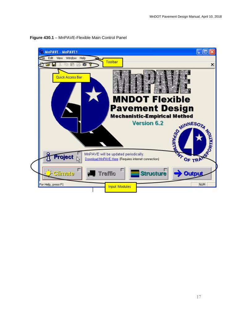
B. Main Control Panel.
MnPAVE-Flexible initially opens to the Main Control Panel (shown in Figure 430.1). The
Main Control Panel contains 5 input modules, a toolbar and a quick access bar that contain
several utilities. MnPAVE-Flexible designs are performed by completing the modules in
order from left to right. A module will not become available for input until the preceding
module has sufficient inputs.
MnDOT Pavement Design Manual, April 10, 2018
17
Figure 430.1 – MnPAVE-Flexible Main Control Panel
MnDOT Pavement Design Manual, April 10, 2018
18
C. Opening and saving a file.
MnPAVE-Flexible will automatically open to a new project. It is recommended to begin a
design by saving the new project. MnPAVE-Flexible saves project files to an .mpv file format
that is unique to MnPAVE-Flexible. A filename that includes the SP number is
recommended.
The following commands can be used to open and save MnPAVE-Flexible files.
(1) The current file can be saved by clicking on , located on the quick access bar or by
selecting "Save" from the "File" menu of the toolbar.
(2) Changes can be saved as a new file name by selecting "Save As" from the "File" menu.
(3) A new MnPAVE-Flexible file can be opened by clicking on the icon or by selecting
"New" from the "File" menu on the toolbar.
(4) An existing MnPAVE-Flexible file can be opened by clicking on the icon or by
selecting "Open" from the file menu. A recently saved file can also be selected from the
list at the bottom of the "File" menu of the toolbar.
MnDOT Pavement Design Manual, April 10, 2018
19
D. Project Information Module
The Project Information Module is a form for entering information necessary to identify a
MnPAVE-Flexible project. MnDOT district, county, city, highway, construction type, design
engineer, and project notes are entered in this module. This data will be retained with the
saved MnPAVE-Flexible file and it will appear on the final design printout.
Identifying the county of the project in the Project Information Module will also locate the
project in the Climate Module. This may be the easiest and most convenient method to locate
the project in the Climate Module. MnPAVE-Flexible will identify the location of the climate
data as the center of the county. The Climate Module will still need to be accessed before
proceeding to the next module will be allowed.
In the notes section,
- For full-depth reclamation (FDR), stabilized full-depth reclamation (SFDR), or cold-in-
place recycling (CIR) projects, identify the existing pavement layers and any milling used in
the pavement design.
- Identify any assumptions that were used for the pavement design.
E. Climate Input Module Figure 430.2 - Project Information Module
MnDOT Pavement Design Manual, April 10, 2018
20
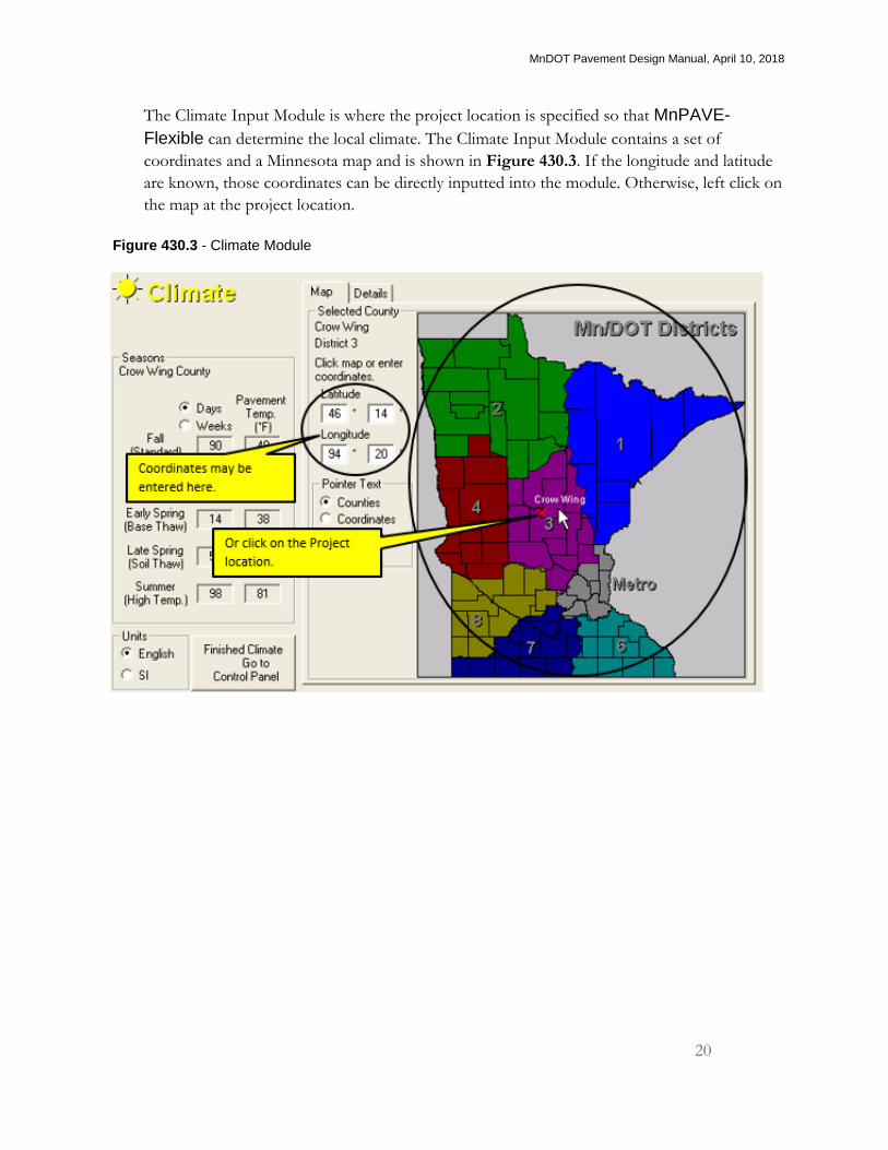
The Climate Input Module is where the project location is specified so that MnPAVE-
Flexible can determine the local climate. The Climate Input Module contains a set of
coordinates and a Minnesota map and is shown in Figure 430.3. If the longitude and latitude
are known, those coordinates can be directly inputted into the module. Otherwise, left click on
the map at the project location.
Figure 430.3 - Climate Module
MnDOT Pavement Design Manual, April 10, 2018
21
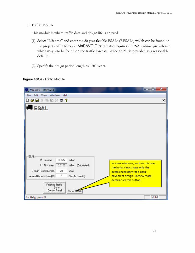
F. Traffic Module
This module is where traffic data and design life is entered.
(1) Select “Lifetime” and enter the 20-year flexible ESALs (BESALs) which can be found on
the project traffic forecast. MnPAVE-Flexible also requires an ESAL annual growth rate
which may also be found on the traffic forecast, although 2% is provided as a reasonable
default.
(2) Specify the design period length as “20” years.
Figure 430.4 - Traffic Module
MnDOT Pavement Design Manual, April 10, 2018
22
G. Structure Module
In the Structure Module, the layers of the pavement structure are identified, by up to five
layers. The user defines the layer thicknesses and materials and may specify some material
properties. MnPAVE-Flexible assigns material properties to the layers based on the user-
defined materials and then creates a model of the pavement structure.
As a rule for MnPAVE-Flexible, use average values for all material inputs. MnPAVE-
Flexible methodology is based on the expectation that any inputs are average and procedures
are included to account for variability in the materials. Outliers may be removed prior to
determining the averages but no reliability factor should be applied.
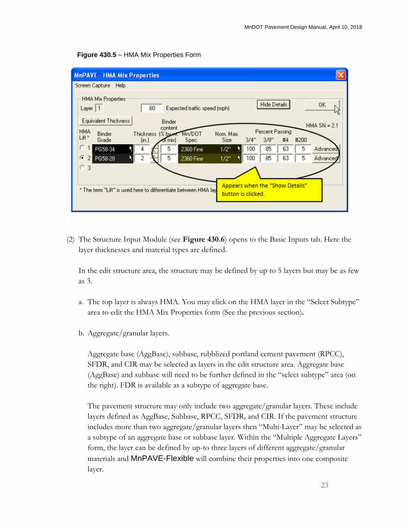
(1) The HMA Mix Properties Form (see Figure 430.5) opens when the Structure Input
Module is initially accessed. This form may also be accessed on the “select sub-type”
section of the Structure Module at a later time. This input screen is where the HMA binder
grade is specified. If “show details” is chosen, the percent binder content and gradation
may be specified. If there are layers (or in MnPAVE-Flexible “lifts”) of HMA with
differing binder grades, binder content, or gradation then the properties of each layer may
be specified here for up to three “lifts.”
a. The HMA Mix Properties Form is where the expected traffic speed is specified. This is
an important input for MnPAVE-Flexible. HMA is a viscoelastic material and is
sensitive to the rate of loading. HMA behaves much stiffer with shorter loading (i.e.,
faster traffic). Conversely, the slower traffic moves, the more time it has to load the
HMA and the more it behaves as a liquid. The standard is to specify the posted speed
limit as the expected speed.
b. When this form is completed, click “OK” to continue to the Structure Input Module.
MnDOT Pavement Design Manual, April 10, 2018
23
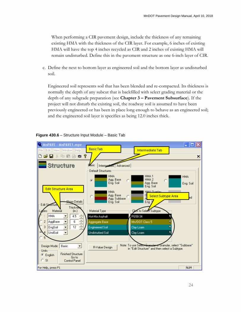
(2) The Structure Input Module (see Figure 430.6) opens to the Basic Inputs tab. Here the
layer thicknesses and material types are defined.
In the edit structure area, the structure may be defined by up to 5 layers but may be as few
as 3.
a. The top layer is always HMA. You may click on the HMA layer in the “Select Subtype”
area to edit the HMA Mix Properties form (See the previous section).
b. Aggregate/granular layers.
Aggregate base (AggBase), subbase, rubblized portland cement pavement (RPCC),
SFDR, and CIR may be selected as layers in the edit structure area. Aggregate base
(AggBase) and subbase will need to be further defined in the “select subtype” area (on
the right). FDR is available as a subtype of aggregate base.
The pavement structure may only include two aggregate/granular layers. These include
layers defined as AggBase, Subbase, RPCC, SFDR, and CIR. If the pavement structure
includes more than two aggregate/granular layers then “Multi-Layer” may be selected as
a subtype of an aggregate base or subbase layer. Within the “Multiple Aggregate Layers”
form, the layer can be defined by up-to three layers of different aggregate/granular
materials and MnPAVE-Flexible will combine their properties into one composite
layer.
Figure 430.5 – HMA Mix Properties Form
MnDOT Pavement Design Manual, April 10, 2018
24
When performing a CIR pavement design, include the thickness of any remaining
existing HMA with the thickness of the CIR layer. For example, 6 inches of existing
HMA will have the top 4 inches recycled as CIR and 2 inches of existing HMA will
remain undisturbed. Define this in the pavement structure as one 6-inch layer of CIR.
c. Define the next to bottom layer as engineered soil and the bottom layer as undisturbed
soil.
Engineered soil represents soil that has been blended and re-compacted. Its thickness is
normally the depth of any subcut that is backfilled with select grading material or the
depth of any subgrade preparation (see Chapter 3 – Pavement Subsurface). If the
project will not disturb the existing soil, the roadway soil is assumed to have been
previously engineered or has been in place long enough to behave as an engineered soil;
and the engineered soil layer is specifies as being 12.0 inches thick.
Figure 430.6 – Structure Input Module – Basic Tab
MnDOT Pavement Design Manual, April 10, 2018
25
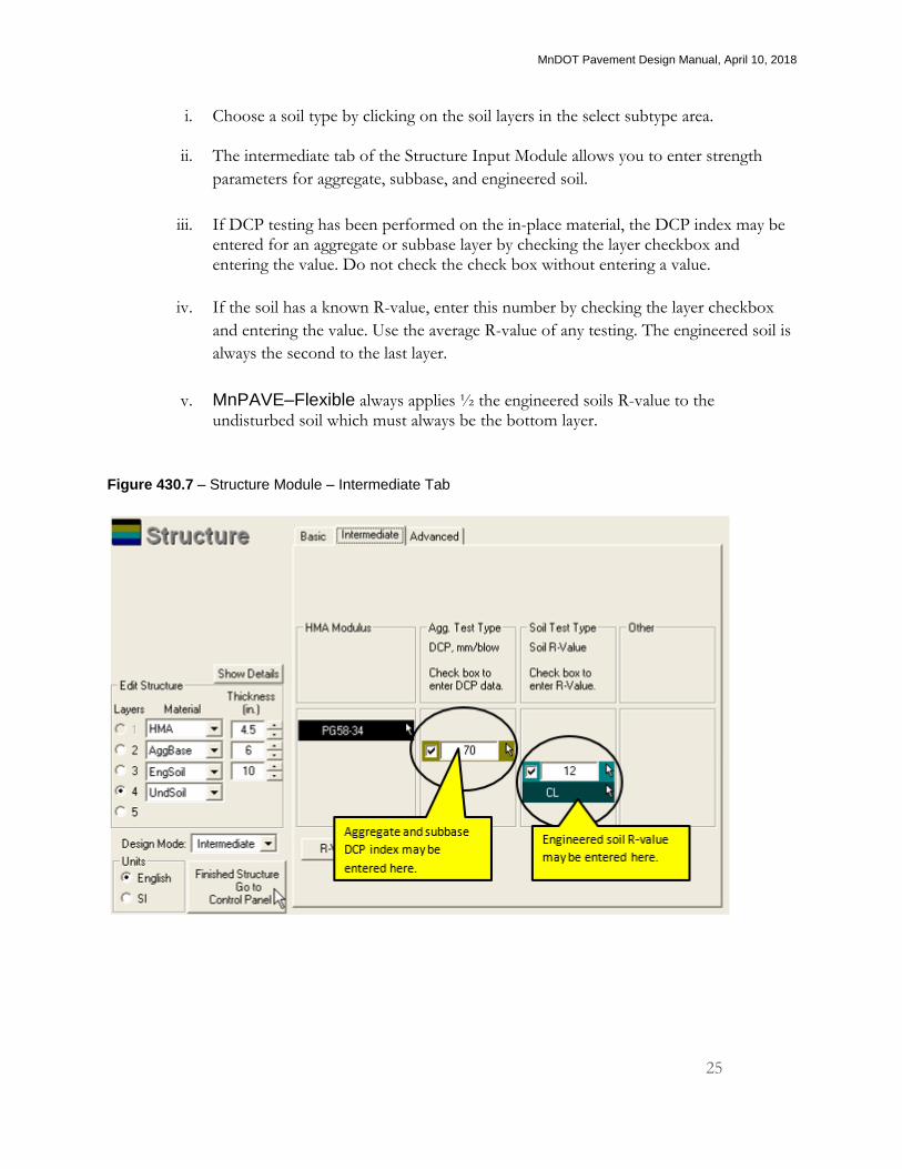
i. Choose a soil type by clicking on the soil layers in the select subtype area.
ii. The intermediate tab of the Structure Input Module allows you to enter strength
parameters for aggregate, subbase, and engineered soil.
iii. If DCP testing has been performed on the in-place material, the DCP index may be entered for an aggregate or subbase layer by checking the layer checkbox and entering the value. Do not check the check box without entering a value.
iv. If the soil has a known R-value, enter this number by checking the layer checkbox
and entering the value. Use the average R-value of any testing. The engineered soil is
always the second to the last layer.
v. MnPAVE–Flexible always applies ½ the engineered soils R-value to the undisturbed soil which must always be the bottom layer.
Figure 430.7 – Structure Module – Intermediate Tab
MnDOT Pavement Design Manual, April 10, 2018
26
D. Output Module
The Output Module (see Figure 430.10) is where the reliability and life expectancy of the
pavement structure is shown. MnPAVE–Flexible models the effect of traffic and climate on
the proposed pavement structure while taking in account variations in layer strengths and
thicknesses. Note: All final designs must meet reliability requirements when using the Monte
Carlo simulation.
(1) The following describes the three different ways that MnPAVE-Flexible models
variations and reliability:
a. The quickest way to model the thickness and strength of the layers is to use a 70%
confidence level. This accounts for variations in the pavement structure and reliability
by simply reducing the strength and thickness of the pavement layers. MnPAVE-
Flexible is able to calculate the estimated years to failure, for fatigue and rutting, almost
immediately using this method. The estimated life shown on the left side of the Output
module is determined with this method.
Allowable stress is also calculated using this method. The allowable stress is the
maximum stress allowed in the aggregate base layer due to a single heavy load event. A
warning will appear immediately if the allowable stress criteria are not met. The
allowable stress warning will indicate the minimum HMA thickness required to meet
the allowable stress criteria.
b. Quick reliability is an estimate of a Monte Carlo simulation.
c. The Monte Carlo simulation is the slowest calculation of the three methods. The time
for running this process ranges from less than one minute to a few minutes. The Monte
Carlo simulation calculates the life of the pavement many times over. Each time, it
varies the pavement layers’ strengths and thicknesses based on their averages and
variances. The reported reliability is the percentage of these calculated lives that met or
exceeded the required design life.
MnDOT Pavement Design Manual, April 10, 2018
27
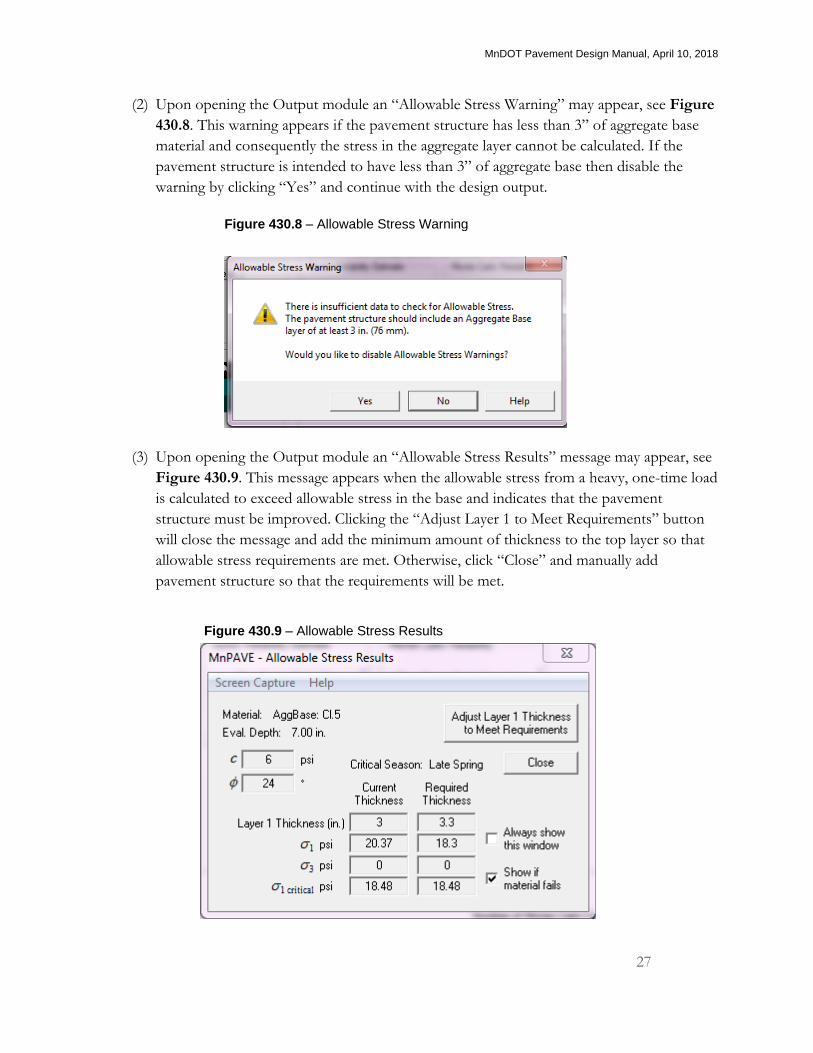
(2) Upon opening the Output module an “Allowable Stress Warning” may appear, see Figure
430.8. This warning appears if the pavement structure has less than 3” of aggregate base
material and consequently the stress in the aggregate layer cannot be calculated. If the
pavement structure is intended to have less than 3” of aggregate base then disable the
warning by clicking “Yes” and continue with the design output.
(3) Upon opening the Output module an “Allowable Stress Results” message may appear, see
Figure 430.9. This message appears when the allowable stress from a heavy, one-time load
is calculated to exceed allowable stress in the base and indicates that the pavement
structure must be improved. Clicking the “Adjust Layer 1 to Meet Requirements” button
will close the message and add the minimum amount of thickness to the top layer so that
allowable stress requirements are met. Otherwise, click “Close” and manually add
pavement structure so that the requirements will be met.
Figure 430.8 – Allowable Stress Warning
Figure 430.9 – Allowable Stress Results
MnDOT Pavement Design Manual, April 10, 2018
28
(4) When the Output Module opens, it immediately calculates the estimated pavement life
using a 70% confidence level. The “thickness goal seek” button can be used to optimize
the layer thicknesses so that the lowest estimated life (fatigue or rutting) equals the design
life. The user has the option to choose the layer to be optimized.
When “thickness goal seek” is used for non-HMA layers, the HMA layer will be adjusted
for fatigue first (if necessary), and then the selected layer thickness will be adjusted. This is
because adjusting underlying layers has a relatively small effect on fatigue life and may
result in very thick layers.
The user may also manually change the thickness of the pavement layers. After any
changes, the recalculate button must be clicked to recalculate the estimated lives with the
new thicknesses.
(5) The Quick Reliability simulation may be initiated prior to the Monte Carlo simulation to
further refine the trial pavement design.
(6) The final pavement design must meet the minimum reliability requirements of the Monte
Carlo simulation for rutting and fatigue. According to the Monte Carlo simulation the final
pavement design must have a reliability of
≥85% for less than 1 million flexible ESALs
≥90 % for 1 million to 15 million flexible ESALs
>95% for more than 15 million flexible ESALs
(7) Whenever possible, the fatigue and rutting years should be within 5 years of each
other to optimize the HMA and granular material thicknesses.
Fatigue life is largely an effect of HMA thickness.
Rutting life is largely an effect of granular material thickness.
(8) Report the final pavement design.
I. Reports A summary report can be saved as PDF file by clicking on the PDF icon on the quick access
bar or by selecting "PDF Design Summary" from the "File" menu.
A screen shot of the output window can be saved by clicking on the camera icon on the quick
access bar. Most other windows have a camera icon that can be clicked to print a screen shot.
MnDOT Pavement Design Manual, April 10, 2018
29
Figure 430.10 – Output Module
MnDOT Pavement Design Manual, April 10, 2018
30
440 - HMA Overlay of Existing Pavement
HMA overlays are placed on existing, intact HMA or PCC pavement that has not been processed
(e.g., FDR, CIR, or rubblization). Typically, HMA overlays are less than 5.0 inches thick.
The performance of an HMA overlay is dependent on the condition of the existing pavement.
Existing cracks, especially transverse thermal cracks, will reflect through the new HMA overlay
which commonly limits the life of HMA overlays. Additionally, frost heaves, subgrade failures,
severe stripping, or rutting of the aggregate base layer may also limit the performance of any HMA
overlay if not repaired. If the roadway has considerable distresses that will limit the life of an HMA
overlay, then consider other rehabilitation techniques. Existing PCC pavements that exhibit
movement (i.e., rocking) are not recommended for a HMA overlay. Instead, to eliminate any
movement, use the crack and seat or rubblization processes (see Section 420 – Rubblization and
Crack and Seat).
Use this section to design HMA overlays of intact HMA or PCC pavements.
1. Use of milling
HMA pavements are often milled prior to placement of a HMA overlay. Leave a sufficient
thickness of existing HMA to support any traffic or construction activities until the HMA overlay
is placed. Milling is used for the following reasons:
A. Milling will help restore the profile of the existing pavement’s surface, remove patching and
sealing materials that may bleed through the overlay, and remove surface distresses that
otherwise might have reflected through the overlay. Typically, milling more than 2.0 inches is
not necessary to attain these benefits.
B. Milling may be used to flatten any bumps or dips in the existing HMA.
C. Milling may be used to remove any stripped or debonded layers in the existing HMA. If the
debonded or stripped layers are too deep to be removed, adjust the milling depth to leave a
sufficient thickness of existing HMA to support any traffic or construction activities until the
HMA overlay is placed.
D. Milling may also be used to lower the existing road surface profile to lessen the grade raise due
to placing an overlay.
MnDOT Pavement Design Manual, April 10, 2018
31
2. Establishing cross-slope
A proper pavement cross-slope (.02 feet/feet) may be constructed by either of these methods.
A. Mill the existing HMA pavement at its existing cross-slope and pave the HMA overlay with
variable thickness to produce the proper pavement cross-slope.
B. Mill the existing HMA pavement at the proper pavement cross-slope and pave the HMA
overlay at one consistent thickness.
3. HMA overlay design life and thickness
A. The design life of an HMA overlay is the number of years until a rehabilitation activity will
occur. Use the HPMA program to predict the performance of the HMA overlay (see Section
280 – Pavement Management System, steps 1-7B for directions) to determine when a
rehabilitation activity will occur; unless Table 440.1 or Table 440.2, or experience, clearly
demonstrates that a different value should be used.
B. For HMA roads that have a seasonal load restriction of less than 10 tons, the thickness of the
HMA overlay necessary to remove the restriction may be calculated using the TONN program
and Falling Weight Deflectometer (FWD) data. See Section 200 - Falling-Weight
Deflectometer (FWD) for guidance in getting and processing FWD data.
4. Background of Tables 440.1 and 440.2
Tables 440.1 and Table 440.2 are the result of a survey, originally performed in 1993, of the
District Materials Engineers and Central Office Pavement Engineers. Averages and standard
deviations of the survey were calculated and outliers (more than 2 standard deviations away from
the average) were eliminated. The averages and standard deviations were recalculated. The tables
basically consist of these averages and standard deviations, with very minor modifications for
uniformity.
These tables were compared to the historical performance of HMA overlays using MnDOT’s
pavement management system to verify that the design life averages and ranges in these tables are
still applicable;. It was determined that the design lives and ranges contained in the tables are
reasonable and remain applicable.
MnDOT Pavement Design Manual, April 10, 2018
32
Table 440.1 - Design lives of HMA overlays of existing HMA
MEDIUM (2-4") OVERLAY
20 Year Flexible ESALS
HIGH MED LOW
Surf
ace C
on
ditio
n
GOOD LIFE 10 12 14
RANGE 2 2 3
FAIR LIFE 8 10 12
RANGE 2 2 2
POOR LIFE 7 8 10
RANGE 2 2 2
THICK (≥4") OVERLAY
20 Year Flexible ESALS
HIGH MED LOW
Surf
ace C
onditio
n
GOOD LIFE 13 15 17
RANGE 2 2 3
FAIR LIFE 11 13 15
RANGE 2 2 3
POOR LIFE 9 11 13
RANGE 2 2 2
MILL & MEDIUM (2-4") OVERLAY
20 Year Flexible ESALS
HIGH MED LOW
Surf
ace C
on
ditio
n
GOOD LIFE 11 13 15
RANGE 3 3 3
FAIR LIFE 9 11 13
RANGE 3 3 3
POOR LIFE 8 10 12
RANGE 3 3 3
MILL & THICK (≥4") OVERLAY
20 Year Flexible ESALS
HIGH MED LOW
Surf
ace C
onditio
n
GOOD LIFE 14 16 19
RANGE 2 2 3
FAIR LIFE 12 14 17
RANGE 2 2 3
POOR LIFE 11 13 16
RANGE 2 2 3
Surface Condition Key
GOOD - Minimal Stripping & No Rutting
FAIR - Severe Transverse Cracking Or Minimal Rutting Or Some Stripping
POOR - Severe Rutting Severe Stripping Or Severe Multiple Cracking
TRAFFIC 20 Year
Flexible ESALS
HIGH >5M
MED 1-5M
LOW <1M

MnDOT Pavement Design Manual, April 10, 2018
33
Table 440.2 - Design lives of HMA overlays of existing PCC
MEDIUM (2-4") OVERLAY
20 Year Flexible ESALS
HIGH MED LOW
Surf
ace C
on
ditio
n
GOOD LIFE 8 10 12
RANGE 2 2 2
FAIR LIFE 6 8 10
RANGE 2 2 2
POOR LIFE 5 6 8
RANGE 2 2 2
THICK (≥4") OVERLAY
20 Year Flexible ESALS
HIGH MED LOW
Surf
ace C
onditio
n
GOOD LIFE 11 13 15
RANGE 2 2 2
FAIR LIFE 10 12 13
RANGE 2 2 2
POOR LIFE 8 10 12
RANGE 2 2 2
MILL & MEDIUM (2-4") OVERLAY
20 Year Flexible ESALS
HIGH MED LOW
Surf
ace C
on
ditio
n
GOOD LIFE 9 11 13
RANGE 2 2 3
FAIR LIFE 7 9 11
RANGE 2 2 3
POOR LIFE 6 8 9
RANGE 2 2 3
MILL & THICK (≥4") OVERLAY
20 Year Flexible ESALS
HIGH MED LOW
Surf
ace C
onditio
n
GOOD LIFE 12 14 17
RANGE 2 3 4
FAIR LIFE 11 13 15
RANGE 2 3 4
POOR LIFE 9 11 13
RANGE 2 3 4
Surface Condition Key
GOOD - Minimal Stripping & No Rutting
FAIR - Severe Transverse Cracking Or Minimal Rutting Or Some Stripping
POOR - Severe Rutting Severe Stripping Or Severe Multiple Cracking
TRAFFIC 20 Year
Flexible ESALS
HIGH >5M
MED 1-5M
LOW <1M
MnDOT Pavement Design Manual, April 10, 2018
34
450 - Materials and Specifications
Use this section to help determine HMA materials (provided with a Mixture Designation Code) and
other specifications that are included in a Materials Design Recommendation (MDR). For more
information and/or assistance on HMA materials, contact the MnDOT Bituminous Engineering
Unit (Office of Materials and Road Research) or visit their website at
http://www.dot.state.mn.us/materials/bituminouscontacts%20new.html.
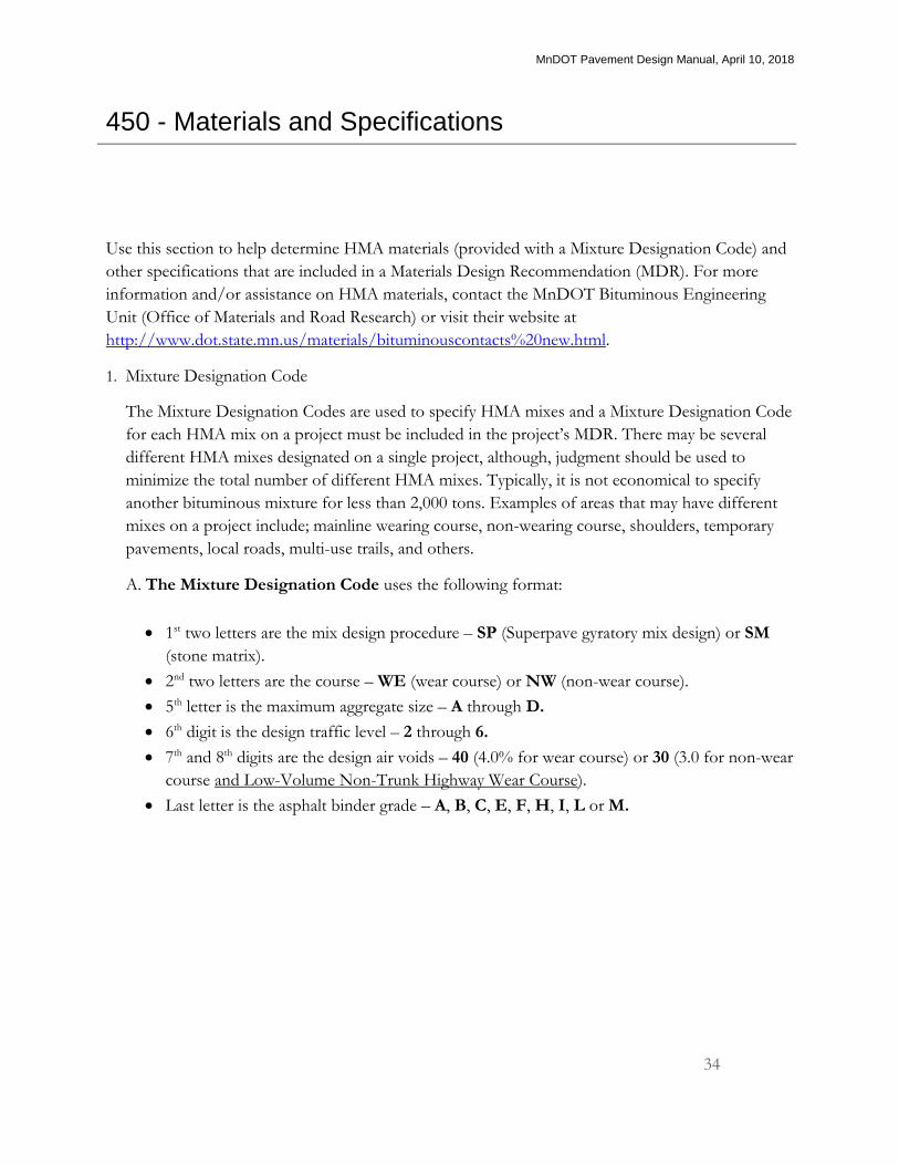
1. Mixture Designation Code
The Mixture Designation Codes are used to specify HMA mixes and a Mixture Designation Code
for each HMA mix on a project must be included in the project’s MDR. There may be several
different HMA mixes designated on a single project, although, judgment should be used to
minimize the total number of different HMA mixes. Typically, it is not economical to specify
another bituminous mixture for less than 2,000 tons. Examples of areas that may have different
mixes on a project include; mainline wearing course, non-wearing course, shoulders, temporary
pavements, local roads, multi-use trails, and others.
A. The Mixture Designation Code uses the following format:
1st two letters are the mix design procedure – SP (Superpave gyratory mix design) or SM
(stone matrix).
2nd two letters are the course – WE (wear course) or NW (non-wear course).
5th letter is the maximum aggregate size – A through D.
6th digit is the design traffic level – 2 through 6.
7th and 8th digits are the design air voids – 40 (4.0% for wear course) or 30 (3.0 for non-wear
course and Low-Volume Non-Trunk Highway Wear Course).
Last letter is the asphalt binder grade – A, B, C, E, F, H, I, L or M.
MnDOT Pavement Design Manual, April 10, 2018
35
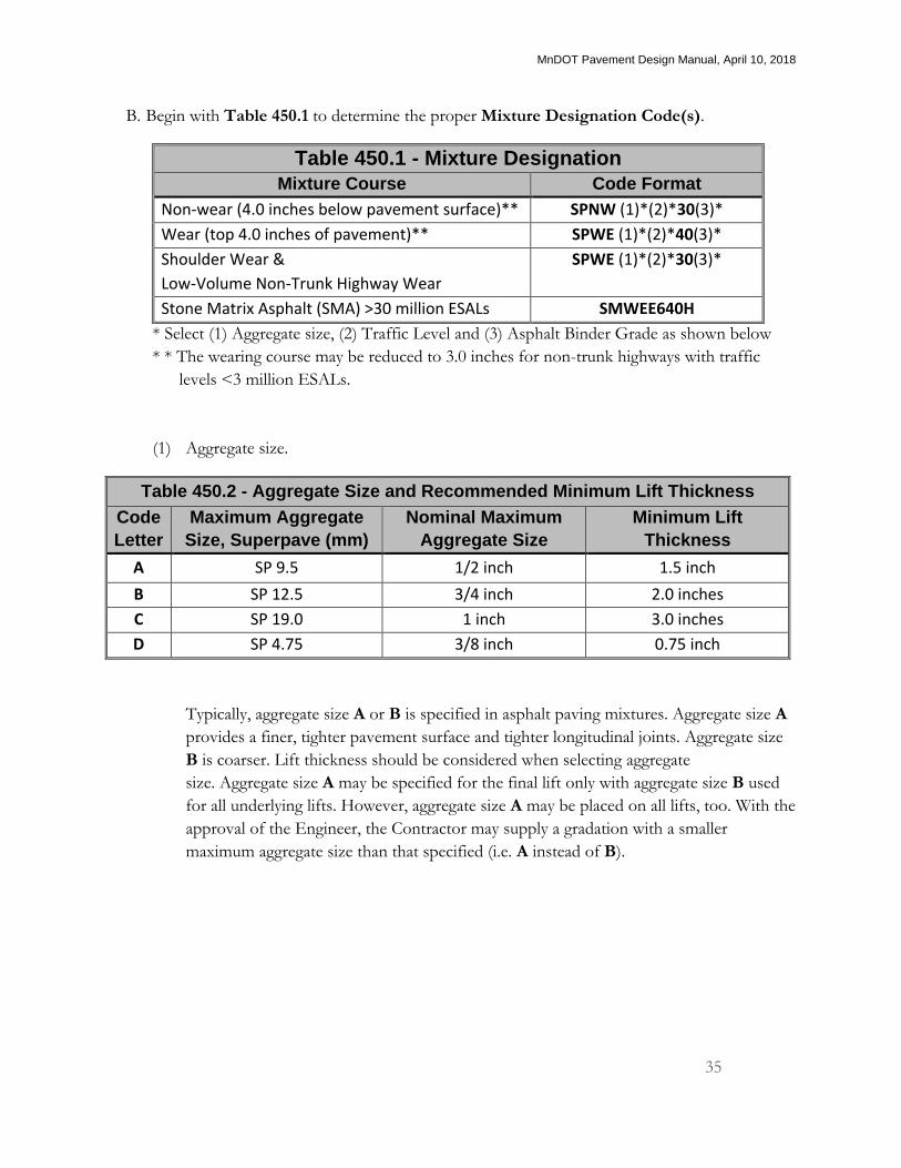
B. Begin with Table 450.1 to determine the proper Mixture Designation Code(s).
Table 450.1 - Mixture Designation
Mixture Course Code Format
Non-wear (4.0 inches below pavement surface)** SPNW (1)*(2)*30(3)*
Wear (top 4.0 inches of pavement)** SPWE (1)*(2)*40(3)*
Shoulder Wear &
Low-Volume Non-Trunk Highway Wear
SPWE (1)*(2)*30(3)*
Stone Matrix Asphalt (SMA) >30 million ESALs SMWEE640H
* Select (1) Aggregate size, (2) Traffic Level and (3) Asphalt Binder Grade as shown below
* * The wearing course may be reduced to 3.0 inches for non-trunk highways with traffic
levels <3 million ESALs.
(1) Aggregate size.
Table 450.2 - Aggregate Size and Recommended Minimum Lift Thickness
Code
Letter
Maximum Aggregate
Size, Superpave (mm)
Nominal Maximum
Aggregate Size
Minimum Lift
Thickness
A SP 9.5 1/2 inch 1.5 inch
B SP 12.5 3/4 inch 2.0 inches
C SP 19.0 1 inch 3.0 inches
D SP 4.75 3/8 inch 0.75 inch
Typically, aggregate size A or B is specified in asphalt paving mixtures. Aggregate size A
provides a finer, tighter pavement surface and tighter longitudinal joints. Aggregate size
B is coarser. Lift thickness should be considered when selecting aggregate
size. Aggregate size A may be specified for the final lift only with aggregate size B used
for all underlying lifts. However, aggregate size A may be placed on all lifts, too. With the
approval of the Engineer, the Contractor may supply a gradation with a smaller
maximum aggregate size than that specified (i.e. A instead of B).
MnDOT Pavement Design Manual, April 10, 2018
36
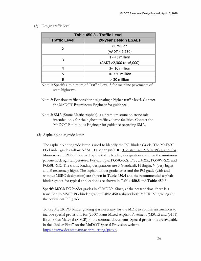
(2) Design traffic level.
Table 450.3 - Traffic Level
Traffic Level 20-year Design ESALs
2 <1 million
(AADT < 2,230)
3 1 - <3 million
(AADT >2,300 to <6,000)
4 3-<10 million
5 10-≤30 million
6 > 30 million
Note 1: Specify a minimum of Traffic Level 3 for mainline pavements of
state highways.
Note 2: For slow traffic consider designating a higher traffic level. Contact
the MnDOT Bituminous Engineer for guidance.
Note 3: SMA (Stone Mastic Asphalt) is a premium stone on stone mix
intended only for the highest traffic volume facilities. Contact the
MnDOT Bituminous Engineer for guidance regarding SMA.
(3) Asphalt binder grade letter
The asphalt binder grade letter is used to identify the PG Binder Grade. The MnDOT
PG binder grades follow AASHTO M332 (MSCR). The standard MSCR PG grades for
Minnesota are PG58, followed by the traffic loading designation and then the minimum
pavement design temperature. For example: PG58S-XX, PG58H-XX, PG58V-XX, and
PG58E-XX. The traffic loading designations are S (standard), H (high), V (very high)
and E (extremely high). The asphalt binder grade letter and the PG grade (with and
without MSRC designation) are shown in Table 450.4 and the recommended asphalt
binder grades for typical applications are shown in Table 450.5 and Table 450.6.
Specify MSCR PG binder grades in all MDR’s. Since, at the present time, there is a
transition to MSCR PG binder grades Table 450.4 shows both MSCR PG grading and
the equivalent PG grade.
To use MSCR PG binder grading it is necessary for the MDR to contain instructions to
include special provisions for (2360) Plant Mixed Asphalt Pavement (MSCR) and (3151)
Bituminous Material (MSCR) in the contract documents. Special provisions are available
in the “Boiler Plate” on the MnDOT Special Provision website
https://www.dot.state.mn.us/pre-letting/prov/.
MnDOT Pavement Design Manual, April 10, 2018
37
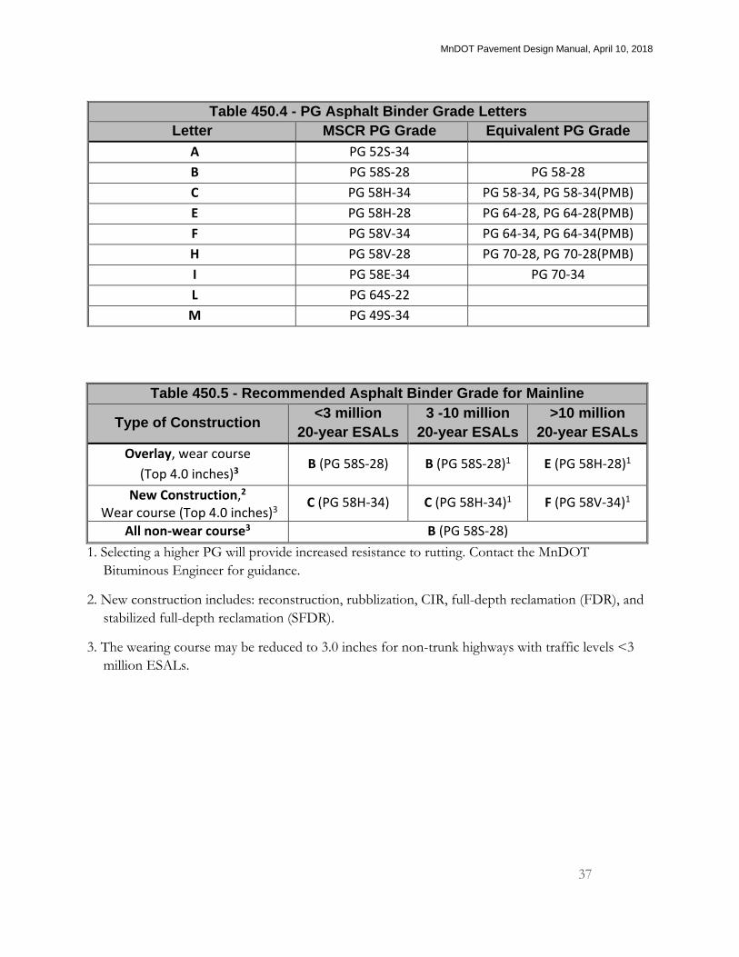
Table 450.5 - Recommended Asphalt Binder Grade for Mainline
Type of Construction <3 million
20-year ESALs
3 -10 million
20-year ESALs
>10 million
20-year ESALs
Overlay, wear course
(Top 4.0 inches)3 B (PG 58S-28) B (PG 58S-28)1 E (PG 58H-28)1
New Construction,2
Wear course (Top 4.0 inches)3 C (PG 58H-34) C (PG 58H-34)1 F (PG 58V-34)1
All non-wear course3 B (PG 58S-28)
1. Selecting a higher PG will provide increased resistance to rutting. Contact the MnDOT
Bituminous Engineer for guidance.
2. New construction includes: reconstruction, rubblization, CIR, full-depth reclamation (FDR), and
stabilized full-depth reclamation (SFDR).
3. The wearing course may be reduced to 3.0 inches for non-trunk highways with traffic levels <3
million ESALs.
Table 450.4 - PG Asphalt Binder Grade Letters
Letter MSCR PG Grade Equivalent PG Grade
A PG 52S-34
B PG 58S-28 PG 58-28
C PG 58H-34 PG 58-34, PG 58-34(PMB)
E PG 58H-28 PG 64-28, PG 64-28(PMB)
F PG 58V-34 PG 64-34, PG 64-34(PMB)
H PG 58V-28 PG 70-28, PG 70-28(PMB)
I PG 58E-34 PG 70-34
L PG 64S-22
M PG 49S-34
MnDOT Pavement Design Manual, April 10, 2018
38
Table 450.6 - Recommended Binder Grade for Shoulders
Traffic Allowed Traffic Prohibited
Next to Concrete
Mainline and Concrete
Curb and Gutter
Generally, the same binder
grade as mainline, but not
to exceed PG 58H-xx.
B (PG 58S-28) or
A (PG 52S-34)
B (PG 58S-28) or
E (PG 58H-28)
Asphalt binder grade notes:
a. Use SMA on the final wearing surface only (top 1.5” – 2” lift). Specify a
minimum PG 70-28 (H) for SMA mixtures. Contact the MnDOT
Bituminous Engineer for guidance.
b. With the agreement of the MnDOT Bituminous Engineer, the designer
may allow, by Special Provision, the Contractor’s option to use PG
64S-22 on overlay construction when both of the following conditions
are met:
Overlay thickness of 3.0 inches or less and
Average in-place crack/joint spacing of 30-feet or less.
The Special Provision will limit the allowable RAP usage to 15% for
mixtures specifying PG 64S-22.
c. For temporary construction (2 years or less) consider using PG64S-22
when PG 58H-28 or PG 58V-34 is otherwise recommended.
d. For special or unique design considerations contact the MnDOT
Bituminous Engineer.
MnDOT Pavement Design Manual, April 10, 2018
39
2. HMA compaction designation
MnDOT Standard Specifications for Construction Specification 2360 include Maximum Density
(2360.3.D1) and Ordinary Compaction (2360.3.D2).
A. Maximum Density Method (2360.3.D1) is the default compaction method and tests if the
pavement’s density meets minimum requirements by cutting cores from the completed
pavement. The bulk density of the cores from the pavement is compared to the maximum
specific gravity of the mixture to determine in-place density. If the designer does not want
Maximum Density as the compaction requirement on a project it must be written out in the
project Special Provisions. Maximum Density should not be specified for temporary work or
on projects with 500 tons or less total tonnage.
B. Ordinary Compaction (2360.3.D2) requires a control strip to be developed to determine the
optimal rolling pattern for compaction and acceptance of the HMA pavement. Specification
2360 defaults to Ordinary Compaction for the following situations:
Layers identified in the typical sections with a minimum planned thickness less than 1½ in.
Thin lift leveling.
Wedging layers.
Patching layers.
Driveways.
Areas the Contractor cannot compact with standard highway construction equipment and
practices.
Bike paths, walking paths, and other similar non-traffic paving areas.
3. HMA lift thickness
The MDR designates the thickness of the individual lifts that will be used to construct the HMA
pavement. The following items should be considered when establishing the lift thicknesses:
The recommended minimum lift thickness for each aggregate size is shown in Table
450.2.
Improved density is the greatest benefit of specifying thicker lifts.
Improved ride is the greatest benefit of paving more lifts (see the following section on
specifying smoothness). However, the ride improvement from 2 to 3 lifts is less than the
improvement from 1 to 2 lifts.
MnDOT Pavement Design Manual, April 10, 2018
40
4. Smoothness
The MDR designates the ride equation or percent ride improvement to apply to HMA paving on
the project. Use the following guidelines to determine which ride equation or percent ride
improvement is appropriate. Consult the MnDOT Bituminous Engineer for other construction
types not covered.
A. For the following construction types, use Equation HMA-A:
New construction with a minimum of 3 lifts.
Overlay with a minimum of 3 lifts and lift thicknesses of at least 1.5 inches.
Construction with a minimum of 3 lifts, with curb and gutter and at least 8 feet separating
the traffic lane from the curb and gutter (i.e. a shoulder at least 8-feet wide).
B. For the following construction types use Equation HMA-B:
New construction with 2 lifts.
Construction with a minimum of 3 lifts, with curb and gutter adjacent to at least one driving
lane.
2-lift overlays with 1.5 inch minimum lift thickness.
Winter-carry-over, wearing course on 2 lifts.
FDR or SFDR with 2 lifts.
Cold-in-place recycled pavements with 2 lifts.
Two lifts over concrete pavement.
C. For single-lift overlay construction on bituminous choose either Equation HMA-C or
Percent Ride Improvement. Percent Ride Improvement is used only on single lift
overlay projects that do not include milling (See Note 1 below for single-lift overlay on
concrete). The Percent Ride Improvement provision compares the smoothness of the roadway
before any construction activities have taken place to the smoothness of the roadway after
construction activities are finished. Incentive/disincentive is determined by the percent ride
improvement. Percent Ride Improvement is intended to be used in situations where the
existing roadway is in poor condition. Data from pilot projects show that the rougher the road
segment to begin with the greater the relative improvement possible. For instance, a road
segment with a starting smoothness of 150 in/mile is more likely to be reduced to a
smoothness of 75 in/mile than a road segment starting at 75 in/mile is to be reduced to a
Smoothness of 37.5 in/mile. Contact the Special Provisions Unit to insert the Percent Ride
Improvement in a Contract.
MnDOT Pavement Design Manual, April 10, 2018
41
For the following construction types, use Percent Ride Improvement (1) (2):
Single-lift bituminous over bituminous (BOB) overlays on a roadway surface with an overall
Ride Quality Index (RQI) < 2.8 (MRI greater than 120 in/mi)*.
For the following construction types, use Equation HMA- C (1):
Single lift bituminous over bituminous (BOB) overlays on a roadway surface with an overall
RQI > 2.8 (MRI 120 in/mi or less)*.
* This information is available in the District’s Pavement Management Condition Rating Reports.
Note 1: Table 2399-2 of the MnDOT Standard Specification excludes smoothness testing of
single-lift overlays on concrete, but requires evaluation of “Areas of Localized Roughness”
(ALR) and the 10-foot straightedge. However, there may be unique situations on single-lift
BOC construction where a smoothness evaluation requirement is appropriate. Consult the
MnDOT Bituminous Engineer for guidance in those considerations.
Note 2: The original smoothness and final smoothness values should be obtained by calendar date
as close to one another as possible. Do not run the original smoothness in one year and the
final smoothness in a different year (i.e. carryover projects).
The following “typical” smoothness values and the equivalent RQI are given for a perspective of
various pavement smoothness numbers:
Table 450.6 Typical Smoothness Values
MRI RQI
New pavement (3-lifts) 37 in/mile 4.1
New pavement (2-lifts) 47 in/mile 3.9
New pavement (1-lift) 60 in/mile 3.6
Aged pavement (10 years) 110 in/mile 2.9
Aged pavement (20 years) 150 in/mile 2.5
Table 2399-2 of the MnDOT Standard Specifications lists pavement surfaces that are excluded from
smoothness testing but subject to evaluation of “Areas of Localized Roughness” (ALR) and the
10-foot straightedge 2360.3E (Surface Requirements). There may be other instances where you feel
the ride specification is not appropriate on a project. In those instances make note in the Special
Provisions that ride will be verified by MnDOT Standard Specification 2360.3E.
MnDOT Pavement Design Manual, April 10, 2018
42
4. Longitudinal joint enhancements
Specify any longitudinal joint enhancements in the MDR for inclusion in a project. These
products are intended to improve the long-term performance of longitudinal “cold” joints in
HMA paving that are often the source of early pavement distress. The following joint
enhancements are available for inclusion in projects and their specifications can be found on the
MnDOT Bituminous Engineering website at
http://www.dot.state.mn.us/materials/bituminousdesignpage.html
A. Fog Sealing: This consists of treating the longitudinal construction joint with a light
application of bituminous material to seal the surface. This treatment is recommended for use
on newly constructed HMA longitudinal joints and can also be used to maintain an existing
longitudinal joint. The fog seal must be applied before permanent pavement markings are
placed or before re-striping of an existing pavement.
B. Joint Adhesive: This is a thick, rubberized asphalt material applied to the vertical face of the
cold joint before the adjacent lane is placed. The material is designed to provide a better bond
between HMA passes and produce a better, more durable longitudinal joint that minimizes the
potential for water infiltration.
C. Joint Stabilization: This consists of applying a fog seal of a bituminous material composed of
petroleum oils and resins emulsified in water over the longitudinal construction joint of a Hot
Mixed Asphalt (HMA). Show in the plans.