M ADE IN U S Electronic Indicator - L. S. Starrett Company
16
Electronic Indicator Operating Manual Backlight Analog Display Analog Visual Display Incremental Measuring Mode SPC Cables USB, MTI, RS232 Measuring System in English or Metric Travel Reverse Green Backlight Yellow Tolerance Warning Backlight Red Out-of-tolerance Warning Backlight User-adjustable Backlight Brightness T.I.R. with Low & High Storage Recall Includes Single Gage Simple Data Collection (One Indicator Per Computer) USB/AC Power Cable Floating Zero Programmable Lock Combination User Tolerance Settings (high & low) Up to 4 User Changeable Resolutions Inch/Metric Display Conversion Maximum Reading Hold Display/Freeze Reading Hold Minimum Reading Hold Absolute/Preset Measuring Mode Large LCD Display MADE IN USA SET 2ND TIR ABS INCR HOLD TOLERANCE FRZ MIN MAX LOW HIGH ON MM IN APPLY HOLD ON/CLR OFF/MODE 2ND TOL IN/MM TRVL MOVE CHANGE
Transcript of M ADE IN U S Electronic Indicator - L. S. Starrett Company
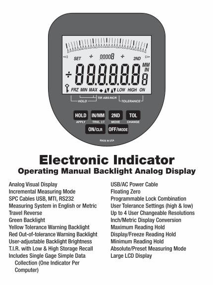
Electronic IndicatorOperating Manual Backlight Analog Display
Analog Visual DisplayIncremental Measuring ModeSPC Cables USB, MTI, RS232Measuring System in English or MetricTravel ReverseGreen BacklightYellow Tolerance Warning BacklightRed Out-of-tolerance Warning BacklightUser-adjustable Backlight BrightnessT.I.R. with Low & High Storage RecallIncludes Single Gage Simple Data
Collection (One Indicator Per Computer)
USB/AC Power CableFloating ZeroProgrammable Lock CombinationUser Tolerance Settings (high & low)Up to 4 User Changeable ResolutionsInch/Metric Display ConversionMaximum Reading HoldDisplay/Freeze Reading HoldMinimum Reading HoldAbsolute/Preset Measuring ModeLarge LCD Display
MADE IN USA
SET 2ND
TIR ABS INCRHOLD TOLERANCE
FRZ MIN MAX LOW HIGH ON
MMIN
APPLY
HOLD
ON/CLR OFF/MODE
2ND TOLIN/MMTRVL MOVE CHANGE
2
TABLE OF CONTENTS
Power Source .............................................................................. 3
Button Functions ......................................................................... 3
Summary Chart For Analog Button Actions ............................... 4
Display-Operating Prompts & Conditions ................................... 5
Power On/Off .............................................................................. 6
Travel Reverse Toggle ................................................................. 6
Change Units ............................................................................... 6
Hold Mode ................................................................................... 7
Tolerance On/Off ........................................................................ 7
Tolerance Settings ...................................................................... 8
Set High Tolerance Number ........................................................ 8
Set Low Tolerance Number......................................................... 9
Change LCD Backlight Brightness Level .................................. 10
Set Absolute Number ................................................................ 11
Lock Toggle ............................................................................... 12
Lock Combination ..................................................................... 12
Reset to Factory Defaults ......................................................... 13
Verify Data I/O Type .................................................................. 13
Set Gage Resolution ................................................................. 14
Display Setup Mode .................................................................. 14
TIR Mode ................................................................................... 15
Custom Applications ................................................................. 16
3
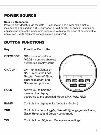
POWER SOURCE
Data I/O ConnectorPower is provided through the data I/O connector. The power cable that is included can be used on a USB port or a 110 volt outlet. For special fixturing or applications where the indicator is integrated with another piece of equipment, a ripple-free 5 VDC regulated voltage source is required.
BUTTON FUNCTIONS
Key Function Controlled
OFF/MODE Off – turns indicator off MODE – controls absolute
numbers & display setup
ON/CLR On – turns indicator on CLR – resets the Lock
Toggle, Data I/O Type, gage resolution, and Display setup mode
HOLD Allows you to hold the
value on the display according to the specified Mode (MAX, MIN, FRZ)
IN/MM Controls the display units (default is English)
2ND Controls the Lock Toggle, Data I/O Type, gage resolution, Travel Reverse and Display setup mode
TOL Controls Low, High and On tolerance settings
MADE IN USA

4
BUTTONFUNCTION
PRIMARY SUBSIDIARY 2ND FUNCTION 3RD FUNCTION
HOLD • Toggle on/off
• Select hold type (MAX, MIN, FRZ) press and hold to step through selection
• Apply function
• Unlocks brightness settings. Use CHANGE to step through selection.
• Apply function
• Enter resolution select process*
• (2ND, ON/CLR, HOLD)
IN/MM• Toggles between
inches, millimeters
• Toggles travel reverse (normal/reverse)
• Resets to factory default settings
• (2ND, ON/CLR, IN/MM)
2ND • Enables 2ND functions
• Move function• Verify data output• (2ND, ON/CLR, 2ND)
TOL • Toggles tolerance on or off
• Select high or low to view or set numbers*
• Change function
• Enter preset setting process*
• Toggles lock on and off; press and release (2ND, ON/CLR, TOL)
• Enters user lock combination setting mode (press and hold to access setting mode)*
ON/CLR • Turn gage on
• Clears/resets display to ‘0’ or spindle position, or ‘abs’ number or ‘abs’ +/- spindle position
• Enables 3RD function
OFF/MODE • Turns gage off
• Select measurement mode (INCR, ABS, TIR) press and hold to step through selection
• Enter display selection style*• (2ND, ON/CLR, OFF/MODE)
* Note: apply, move and change are automatically active when in preset, lock and tolerance setting modes. Apply and change are automatically active when in resolution set mode.
SUMMARY CHART FOR ANALOG BUTTON ACTIONSButton actions occur on the press of the button in most cases. Some button presses will have the action occur on the release of the button press. For example, when the ‘ON/CLR’ button is used to clear the display, the action is to happen on the release of the button. When the ‘ON/CLR’ button is used as the 2nd function in a sequence of button pushes, the action can be on the press of the button. Whenever a button press requires a continuous press to scroll through some selection process, the action of the button is on the release of the button.
5
MMIN
MADE IN USA
HOLD
ON/CLR OFF/MODE
IN/MM
MIN MAXFRZ LOW HIGH ON
SET 2ND
TIR ABS INCRTOLERANCE
APPLY TRVL MOVE CHANGE
HOLD
2ND TOL
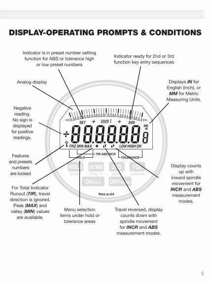
DISPLAY-OPERATING PROMPTS & CONDITIONS
Negative reading.
No sign is displayed
for positive readings.
Features and presets
numbers are locked
Analog display
Indicator is in preset number setting function for ABS or tolerance high
or low preset numbers
Indicator ready for 2nd or 3rd function key entry sequences
Displays IN for English (inch), or MM for Metric
Measuring Units.
For Total Indicator Runout (TIR), travel direction is ignored.
Peak (MAX) and valley (MIN) values
are available.
Display counts up with
inward spindle movement for
INCR and ABS measurement
modes.
Travel reversed, display counts down with spindle movement for INCR and ABS
measurement modes.
Menu selection items under hold or
tolerance areas
6
OPERATING INSTRUCTIONS
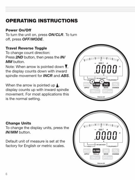
Power On/OffTo turn the unit on, press ON/CLR. To turn off, press OFF/MODE.
Travel Reverse ToggleTo change count direction:Press 2ND button, then press the IN/MM button. Note: When arrow is pointed down , the display counts down with inward spindle movement for INCR and ABS.
When the arrow is pointed up , display counts up with inward spindle movement. For most applications this is the normal setting.
Change UnitsTo change the display units, press the IN/MM button.
Default unit of measure is set at the factory for English or metric scales.
IN
MADE IN USA
HOLD
ON/CLR OFF/MODE
IN/MM
TIR ABS INCRTOLERANCE
APPLY TRVL MOVE CHANGE
HOLD
2ND TOL12
IN
MADE IN USA
HOLD
ON/CLR OFF/MODE
IN/MM
TIR ABS INCRTOLERANCE
APPLY TRVL MOVE CHANGE
HOLD
2ND TOL
7
OPERATING INSTRUCTIONS
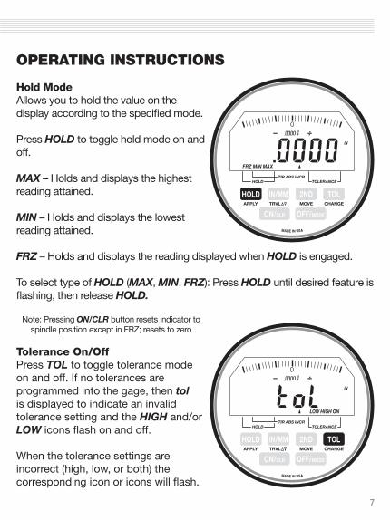
Hold ModeAllows you to hold the value on the display according to the specified mode.
Press HOLD to toggle hold mode on and off.
MAX – Holds and displays the highest reading attained.
MIN – Holds and displays the lowest reading attained.
FRZ – Holds and displays the reading displayed when HOLD is engaged.
To select type of HOLD (MAX, MIN, FRZ): Press HOLD until desired feature is flashing, then release HOLD.
Note: Pressing ON/CLR button resets indicator to spindle position except in FRZ; resets to zero
Tolerance On/OffPress TOL to toggle tolerance mode on and off. If no tolerances are programmed into the gage, then tol is displayed to indicate an invalid tolerance setting and the HIGH and/or LOW icons flash on and off.
When the tolerance settings are incorrect (high, low, or both) the corresponding icon or icons will flash.
IN
MADE IN USA
HOLD
ON/CLR OFF/MODE
IN/MM
TIR ABS INCRTOLERANCE
APPLY TRVL MOVE CHANGE
HOLD
2ND TOL
MIN MAXFRZ
IN
MADE IN USA
HOLD
ON/CLR OFF/MODE
IN/MM
TIR ABS INCRTOLERANCE
APPLY TRVL MOVE CHANGE
HOLD
2ND TOL
LOW HIGH ON

8
OPERATING INSTRUCTIONS
Tolerance SettingsContinuously press the TOL button to activate the tolerance menu (LOW, HIGH, ON) and view the low and high tolerance settings.
If no preset tolerance number is set into the gage then zero will be displayed.
When viewing low or high, that icon will flash.
Set High Tolerance NumberWhile in tolerance mode, continuously press the TOL (CHANGE) button until the HIGH icon flashes, then release button. Press 2ND button (2ND icon should appear on the display). Press the TOL (CHANGE) button.
Use the secondary function buttons, CHANGE and MOvE, to set your tolerance setting. After you have set your high tolerance setting, press AppLy to store numbers to memory.
IN
MADE IN USA
HOLD
ON/CLR OFF/MODE
IN/MM
TIR ABS INCRTOLERANCE
APPLY TRVL MOVE CHANGE
HOLD
2ND TOL
LOW HIGH ON
SET
IN
MADE IN USA
HOLD
ON/CLR OFF/MODE
IN/MM
TIR ABS INCRTOLERANCE
APPLY TRVL MOVE CHANGE
HOLD
2ND TOL
LOW HIGH ON
1 2

9
OPERATING INSTRUCTIONS
Set Low Tolerance NumberWhile in tolerance mode, continuously press the TOL (CHANGE) button until the LOW icon flashes, then release button. Press 2ND button (2ND icon should appear on the display). Press the TOL (CHANGE) button.
Use the secondary function buttons, CHANGE and MOvE, to set your tolerance setting. After you have set your low tolerance setting, press AppLy to store numbers to memory.
Note: once high and low tolerances are set, the LCD will turn yellow when the reading value is more than 80% of the high or low set tolerance (if yellow warning feature is turned on), and will turn red when readings are out of tolerance.
The tolerance function must be programmed and turned on for the LCD to turn red.
Green and red LCD brightness levels can be adjusted. Yellow warning brightness is based on the brightness of the programmed green and red LCD settings. The yellow warning can be turned on or off.
Operator can program the color in this sequence: green, red and then yellow.
SET
IN
MADE IN USA
HOLD
ON/CLR OFF/MODE
IN/MM
TIR ABS INCR
TOLERANCE
APPLY TRVL MOVE CHANGE
HOLD
2ND TOL
LOW HIGH ON
1 2

10
OPERATING INSTRUCTIONS
To change brightness level of the LCD backlight and turn yellow warning on/off: Press and release the 2ND button. Press and release the HOLD button. Use the CHANGE (TOL) button to scroll through green brightness levels. Use the AppLy (HOLD) button to set the green brightness level. Use the CHANGE (TOL) button to scroll through red brightness levels. Use the AppLy (HOLD) button to set the red brightness level. Use the CHANGE (TOL) button to turn the yellow “Warn” on or off. Use the AppLy (HOLD) button to set ON or OFF.
SET
IN
MADE IN USA
HOLD
ON/CLR OFF/MODE
IN/MM
TIR ABS INCR
TOLERANCE
APPLY TRVL MOVE CHANGE
HOLD
2ND TOL
LOW HIGH ON
1 2
11
OPERATING INSTRUCTIONS
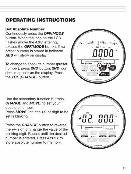
Set Absolute NumberContinuously press the OFF/MODE button. When the icon on the LCD flashes above the ABS lettering, release the OFF/MODE button. If no preset number is stored in indicator ABS will show on display.
To change to absolute number (preset number), press 2ND button; 2ND icon should appear on the display. Press the TOL (CHANGE) button.
Use the secondary function buttons, CHANGE and MOvE, to set your absolute number. Press MOvE until the +/- or digit to be set is blinking.
Press the CHANGE button to reverse the +/- sign or change the value of the blinking digit. Repeat until the desired number is entered. Press AppLy to store absolute number to memory.
SET
IN
MADE IN USA
HOLD
ON/CLR OFF/MODE
IN/MM
TIR ABS INCRTOLERANCE
APPLY TRVL MOVE CHANGE
HOLD
2ND TOL
2ND
IN
MADE IN USA
HOLD
ON/CLR OFF/MODE
IN/MM
TIR ABS INCRTOLERANCE
APPLY TRVL MOVE CHANGE
HOLD
2ND TOL
1
2 3
12
OPERATING INSTRUCTIONS
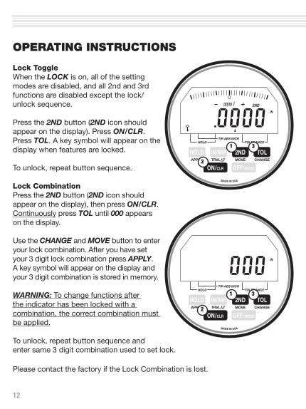
Lock ToggleWhen the LOCK is on, all of the setting modes are disabled, and all 2nd and 3rd functions are disabled except the lock/unlock sequence.
Press the 2ND button (2ND icon should appear on the display). Press ON/CLR. Press TOL. A key symbol will appear on the display when features are locked.
To unlock, repeat button sequence.
Lock CombinationPress the 2ND button (2ND icon should appear on the display), then press ON/CLR. Continuously press TOL until 000 appears on the display.
Use the CHANGE and MOvE button to enter your lock combination. After you have set your 3 digit lock combination press AppLy. A key symbol will appear on the display and your 3 digit combination is stored in memory.
WARNING: To change functions after the indicator has been locked with a combination, the correct combination must be applied.
To unlock, repeat button sequence and enter same 3 digit combination used to set lock.
Please contact the factory if the Lock Combination is lost.
2ND
IN
MADE IN USA
HOLD
ON/CLR OFF/MODE
IN/MM
TIR ABS INCRTOLERANCE
APPLY TRVL MOVE CHANGE
HOLD
2ND TOL1
2
3
IN
MADE IN USA
HOLD
ON/CLR OFF/MODE
IN/MM
TIR ABS INCRTOLERANCE
APPLY TRVL MOVE CHANGE
HOLD
2ND TOL1
2
3

13
OPERATING INSTRUCTIONS
Reset to Factory DefaultsThis will set all features and functions back to the factory default settings.
Press the 2ND button (2ND icon should appear on the display), followed by ON/CLR, then press IN/MM.
Note: Factory defaults cannot be reset if the LOCK feature is on.
Verify Data I/O TypeTo view the Data I/O Type Output, press the 2ND button. The 2ND icon will appear on the display. Press ON/CLR. Press 2ND. Format information is displayed on the LCD. USB, SER, MTI, or BIpASS will appear on the LCD.
To exit: Repeat button sequence.
2ND
IN
MADE IN USA
HOLD
ON/CLR OFF/MODE
IN/MM
TIR ABS INCRTOLERANCE
APPLY TRVL MOVE CHANGE
HOLD
2ND TOL13
2
MADE IN USA
HOLD
ON/CLR OFF/MODE
IN/MM
TIR ABS INCRTOLERANCE
APPLY TRVL MOVE CHANGE
HOLD
2ND TOL1
2
3

14
OPERATING INSTRUCTIONS
Set Gage ResolutionFor the change resolution feature: Press 2ND, press ON/CLR, then press HOLD.
After that, each press of the CHANGE Button (TOL) steps through the available resolution options: .001˝, .0005˝, .0001˝ or .00005˝ *
*Note: Only resolutions coarser than resolution of purchased indicator are available.
Analog graduations are set to match gage resolution. Press the AppLy button to store the resolution setting. Display returns to measuring mode at desired resolution, but does not change displayed value.
Display Setup ModeTo change the display configuration, press the 2ND button, followed by the ON/CLR button. Then press the OFF/MODE button to enter the display configuration setting mode.
The whole display flashes.
Press CHANGE to cycle through the display options and choose AppLy to save the current display configuration. There are five display options. For example, the analog display can be turned off or the numbers can be turned off.
IN
MADE IN USA
HOLD
ON/CLR OFF/MODE
IN/MM
TIR ABS INCRTOLERANCE
APPLY TRVL MOVE CHANGE
HOLD
2ND TOL
SET
1
2
3
IN
MADE IN USA
HOLD
ON/CLR OFF/MODE
IN/MM
TIR ABS INCRTOLERANCE
APPLY TRVL MOVE CHANGE
HOLD
2ND TOL
SET
1
2 3

15
OPERATING INSTRUCTIONS
TIR ModeTotal Indicator Runout (TIR) mode ignores travel direction, instead measuring the difference between peak and valley (MAX and MIN) values.
To enter TIR Mode, continuously press the OFF/MODE button until the diamond icon flashes above the TIR function, then release the OFF/MODE button.
In TIR mode, the Freeze (FRZ) is the only hold function available.
To view the Peak (MAX) Value or the Valley (MIN) Value, use the HOLD button. Press HOLD button down until the MIN or MAX is displayed.
The difference between the MIN and MAX Values equals the TIR Value.
IN
MADE IN USA
IN
MADE IN USA

16
CUSTOM APPLICATIONS
Custom LCDs and graphics can be provided for almost any application. We can help you design a gage for your exacting requirements.
Keypads and features can be customized to meet most needs. For example, a gage can be programmed for T.I.R. only, or a gage can be programmed so only selected features are available.
With our programmable software and flexible microchip, the possibilities are limited only by your imagination.
Custom hardware is available to fit your specifications. For example, a gage can be made without a return spring or with a custom spring. Special length stems, threaded stems, backs, and contact points, are also available.
Backlight Indicators are available in the following travels and resolutions:
Travel Resolution
1˝ .0001˝ 1˝ .00005˝ 2˝ .0005˝ 2˝ .0001˝ 4˝ .0005˝ 4˝ .0001˝
MADE IN USA
Part No. K04-0106