m 74634 190ultracount
67
74634 DC-190 ULTRA COUNT Counting Scale Version 4.0 Installation Manual
Transcript of m 74634 190ultracount

DC-190U L T R A C O U N T
Counting ScaleVersion 4.0
Installation Manual
74634


Contents
About This Manual ................................................................................................................................... 11.0 Introduction.................................................................................................................................. 1
1.1 Unpacking and Inspection . . . . . . . . . . . . . . . . . . . . . . . . . . . . . . . . . . . . . . . . . . . . . . . . . . . . . . . . . 21.2 Repacking . . . . . . . . . . . . . . . . . . . . . . . . . . . . . . . . . . . . . . . . . . . . . . . . . . . . . . . . . . . . . . . . . . . . . 21.3 DC-190 Scale Capacities and Resolutions. . . . . . . . . . . . . . . . . . . . . . . . . . . . . . . . . . . . . . . . . . . . . 21.4 DC-190 Console . . . . . . . . . . . . . . . . . . . . . . . . . . . . . . . . . . . . . . . . . . . . . . . . . . . . . . . . . . . . . . . . 4
1.4.1 Annunciators. . . . . . . . . . . . . . . . . . . . . . . . . . . . . . . . . . . . . . . . . . . . . . . . . . . . . . . . . . . . . . . . . . . . . 41.4.2 DC-190 Keypad . . . . . . . . . . . . . . . . . . . . . . . . . . . . . . . . . . . . . . . . . . . . . . . . . . . . . . . . . . . . . . . . . . 5
2.0 Installation ................................................................................................................................... 62.1 Locking and Unlocking . . . . . . . . . . . . . . . . . . . . . . . . . . . . . . . . . . . . . . . . . . . . . . . . . . . . . . . . . . . 62.2 Setting Up . . . . . . . . . . . . . . . . . . . . . . . . . . . . . . . . . . . . . . . . . . . . . . . . . . . . . . . . . . . . . . . . . . . . . 62.3 Powering Up the DC-190 . . . . . . . . . . . . . . . . . . . . . . . . . . . . . . . . . . . . . . . . . . . . . . . . . . . . . . . . . 7
2.3.1 AC Power Source . . . . . . . . . . . . . . . . . . . . . . . . . . . . . . . . . . . . . . . . . . . . . . . . . . . . . . . . . . . . . . . . . 72.3.2 DC Battery Pack Replacement/Installation . . . . . . . . . . . . . . . . . . . . . . . . . . . . . . . . . . . . . . . . . . . . . . 72.3.3 DC Battery Operation . . . . . . . . . . . . . . . . . . . . . . . . . . . . . . . . . . . . . . . . . . . . . . . . . . . . . . . . . . . . . . 82.3.4 Battery Charging. . . . . . . . . . . . . . . . . . . . . . . . . . . . . . . . . . . . . . . . . . . . . . . . . . . . . . . . . . . . . . . . . . 8
2.4 Setting Time and Date . . . . . . . . . . . . . . . . . . . . . . . . . . . . . . . . . . . . . . . . . . . . . . . . . . . . . . . . . . . . 82.5 Installing Cable Strain Relief . . . . . . . . . . . . . . . . . . . . . . . . . . . . . . . . . . . . . . . . . . . . . . . . . . . . . . . . 92.6 Pole Mounting Instructions . . . . . . . . . . . . . . . . . . . . . . . . . . . . . . . . . . . . . . . . . . . . . . . . . . . . . . . . 92.7 Load Cell Replacement . . . . . . . . . . . . . . . . . . . . . . . . . . . . . . . . . . . . . . . . . . . . . . . . . . . . . . . . . . 10
2.7.1 Single-Platform Load Cell Replacement . . . . . . . . . . . . . . . . . . . . . . . . . . . . . . . . . . . . . . . . . . . . . . . 102.7.2 Dual-Platform Load Cell Replacement. . . . . . . . . . . . . . . . . . . . . . . . . . . . . . . . . . . . . . . . . . . . . . . . . 11
3.0 Scale Setup................................................................................................................................ 123.1 Scale Configurations . . . . . . . . . . . . . . . . . . . . . . . . . . . . . . . . . . . . . . . . . . . . . . . . . . . . . . . . . . . . 12
3.1.1 Configuring SPECs 16 and 17 . . . . . . . . . . . . . . . . . . . . . . . . . . . . . . . . . . . . . . . . . . . . . . . . . . . . . . 123.1.2 Scale Configurations, No Force Balance Attached . . . . . . . . . . . . . . . . . . . . . . . . . . . . . . . . . . . . . . . 133.1.3 Scale Configurations, Including Force Balance . . . . . . . . . . . . . . . . . . . . . . . . . . . . . . . . . . . . . . . . . . 14
3.2 Serial Configurations . . . . . . . . . . . . . . . . . . . . . . . . . . . . . . . . . . . . . . . . . . . . . . . . . . . . . . . . . . . . 143.2.1 Configuring SPEC 13 . . . . . . . . . . . . . . . . . . . . . . . . . . . . . . . . . . . . . . . . . . . . . . . . . . . . . . . . . . . . . 153.2.2 FORCE BALANCE (DIN-8) and 232C/PRINTER (D-Sub) Port Connections . . . . . . . . . . . . . . . . . . . . . 163.2.3 SCANNER Port Connections . . . . . . . . . . . . . . . . . . . . . . . . . . . . . . . . . . . . . . . . . . . . . . . . . . . . . . . 16
4.0 Configuration Settings ............................................................................................................... 174.1 Configuration Procedure . . . . . . . . . . . . . . . . . . . . . . . . . . . . . . . . . . . . . . . . . . . . . . . . . . . . . . . . . 174.2 Customer Specification (141 Settings) . . . . . . . . . . . . . . . . . . . . . . . . . . . . . . . . . . . . . . . . . . . . . . . 184.3 Weight and Measurement Specifications (142 Settings) . . . . . . . . . . . . . . . . . . . . . . . . . . . . . . . . . . 214.4 RS-232 Specifications (143 Settings). . . . . . . . . . . . . . . . . . . . . . . . . . . . . . . . . . . . . . . . . . . . . . . . 24
5.0 Calibration.................................................................................................................................. 256.0 Scale Operations........................................................................................................................ 26
6.1 Entering Tare Weights . . . . . . . . . . . . . . . . . . . . . . . . . . . . . . . . . . . . . . . . . . . . . . . . . . . . . . . . . . . 266.2 Toggle Between Scales . . . . . . . . . . . . . . . . . . . . . . . . . . . . . . . . . . . . . . . . . . . . . . . . . . . . . . . . . . 276.3 Toggling Between Net and Gross Weight . . . . . . . . . . . . . . . . . . . . . . . . . . . . . . . . . . . . . . . . . . . . 276.4 Entering Unit Weights . . . . . . . . . . . . . . . . . . . . . . . . . . . . . . . . . . . . . . . . . . . . . . . . . . . . . . . . . . . 27
6.4.1 Unit Weight Operation by Sampling. . . . . . . . . . . . . . . . . . . . . . . . . . . . . . . . . . . . . . . . . . . . . . . . . . . 276.4.2 Unit Weight Operation by Key Entry . . . . . . . . . . . . . . . . . . . . . . . . . . . . . . . . . . . . . . . . . . . . . . . . . . 286.4.3 Clearing Unit Weight . . . . . . . . . . . . . . . . . . . . . . . . . . . . . . . . . . . . . . . . . . . . . . . . . . . . . . . . . . . . . . 28
6.5 Part Accumulation and Reduction–Without Recalling an Item Code. . . . . . . . . . . . . . . . . . . . . . . . . 286.5.1 Part Accumulation. . . . . . . . . . . . . . . . . . . . . . . . . . . . . . . . . . . . . . . . . . . . . . . . . . . . . . . . . . . . . . . . 286.5.2 Part Reduction . . . . . . . . . . . . . . . . . . . . . . . . . . . . . . . . . . . . . . . . . . . . . . . . . . . . . . . . . . . . . . . . . . 286.5.3 Clearing Accumulated Data. . . . . . . . . . . . . . . . . . . . . . . . . . . . . . . . . . . . . . . . . . . . . . . . . . . . . . . . . 29
6.6 Other Operations . . . . . . . . . . . . . . . . . . . . . . . . . . . . . . . . . . . . . . . . . . . . . . . . . . . . . . . . . . . . . . . 296.6.1 Set New Vendor Name . . . . . . . . . . . . . . . . . . . . . . . . . . . . . . . . . . . . . . . . . . . . . . . . . . . . . . . . . . . . 296.6.2 Set New Operator Name. . . . . . . . . . . . . . . . . . . . . . . . . . . . . . . . . . . . . . . . . . . . . . . . . . . . . . . . . . . 296.6.3 Set New Batch Print Quantity . . . . . . . . . . . . . . . . . . . . . . . . . . . . . . . . . . . . . . . . . . . . . . . . . . . . . . . 296.6.4 Set New Sequence Number . . . . . . . . . . . . . . . . . . . . . . . . . . . . . . . . . . . . . . . . . . . . . . . . . . . . . . . . 29
© 2003 Rice Lake Weighing Systems. All rights reserved. Printed in the United States of America. Specifications subject to change without notice.
October 2003

7.0 Scale Programming................................................................................................................... 307.1 Item Code Storage . . . . . . . . . . . . . . . . . . . . . . . . . . . . . . . . . . . . . . . . . . . . . . . . . . . . . . . . . . . . . . 307.2 Item Code Maintenance . . . . . . . . . . . . . . . . . . . . . . . . . . . . . . . . . . . . . . . . . . . . . . . . . . . . . . . . . . 317.3 Using Item Code in Normal Mode . . . . . . . . . . . . . . . . . . . . . . . . . . . . . . . . . . . . . . . . . . . . . . . . . . . 32
7.3.1 Inventory Operations Related to the Item Code Quantity Value . . . . . . . . . . . . . . . . . . . . . . . . . . . . . . 337.4 Global Setpoint Programming– Setpoints Not Tied to an Item Code . . . . . . . . . . . . . . . . . . . . . . . . . 34
7.4.1 Procedure . . . . . . . . . . . . . . . . . . . . . . . . . . . . . . . . . . . . . . . . . . . . . . . . . . . . . . . . . . . . . . . . . . . . . 34
8.0 RS-232 Specifications ............................................................................................................... 358.1 RS-232 Ports . . . . . . . . . . . . . . . . . . . . . . . . . . . . . . . . . . . . . . . . . . . . . . . . . . . . . . . . . . . . . . . . . . 358.2 Eltron Printers . . . . . . . . . . . . . . . . . . . . . . . . . . . . . . . . . . . . . . . . . . . . . . . . . . . . . . . . . . . . . . . . . . 368.3 Epson Tape Printers . . . . . . . . . . . . . . . . . . . . . . . . . . . . . . . . . . . . . . . . . . . . . . . . . . . . . . . . . . . . . 378.4 Epson Ticket Printers . . . . . . . . . . . . . . . . . . . . . . . . . . . . . . . . . . . . . . . . . . . . . . . . . . . . . . . . . . . . 388.5 Digi BCP-300 Printer . . . . . . . . . . . . . . . . . . . . . . . . . . . . . . . . . . . . . . . . . . . . . . . . . . . . . . . . . . . . 388.6 PC Output Data Formats . . . . . . . . . . . . . . . . . . . . . . . . . . . . . . . . . . . . . . . . . . . . . . . . . . . . . . . . . 39
8.6.1 PC Output Data Format With Header . . . . . . . . . . . . . . . . . . . . . . . . . . . . . . . . . . . . . . . . . . . . . . . . . 398.6.2 PC Output Data Format Without Header . . . . . . . . . . . . . . . . . . . . . . . . . . . . . . . . . . . . . . . . . . . . . . 40
8.7 Data . . . . . . . . . . . . . . . . . . . . . . . . . . . . . . . . . . . . . . . . . . . . . . . . . . . . . . . . . . . . . . . . . . . . . . . . . 408.8 Status Data Byte. . . . . . . . . . . . . . . . . . . . . . . . . . . . . . . . . . . . . . . . . . . . . . . . . . . . . . . . . . . . . . . . 418.9 Bar Code Scanners . . . . . . . . . . . . . . . . . . . . . . . . . . . . . . . . . . . . . . . . . . . . . . . . . . . . . . . . . . . . . 428.10 Header . . . . . . . . . . . . . . . . . . . . . . . . . . . . . . . . . . . . . . . . . . . . . . . . . . . . . . . . . . . . . . . . . . . . . . 428.11 Z Commands . . . . . . . . . . . . . . . . . . . . . . . . . . . . . . . . . . . . . . . . . . . . . . . . . . . . . . . . . . . . . . . . . 43
9.0 PC Connections and Label Formatting ...................................................................................... 449.1 Using HyperTerminal. . . . . . . . . . . . . . . . . . . . . . . . . . . . . . . . . . . . . . . . . . . . . . . . . . . . . . . . . . . . . 44
9.1.1 HyperTerminal Setup . . . . . . . . . . . . . . . . . . . . . . . . . . . . . . . . . . . . . . . . . . . . . . . . . . . . . . . . . . . . . 449.1.2 Using HyperTerminal to Request Data . . . . . . . . . . . . . . . . . . . . . . . . . . . . . . . . . . . . . . . . . . . . . . . . 449.1.3 Saving Data Sent to HyperTerminal . . . . . . . . . . . . . . . . . . . . . . . . . . . . . . . . . . . . . . . . . . . . . . . . . . 449.1.4 Example of HyperTerminal Data . . . . . . . . . . . . . . . . . . . . . . . . . . . . . . . . . . . . . . . . . . . . . . . . . . . . . 45
9.2 Creating Labels for Eltron 2700-Series Printers . . . . . . . . . . . . . . . . . . . . . . . . . . . . . . . . . . . . . . . . . 469.2.1 Editing Text and Bar Code Fields . . . . . . . . . . . . . . . . . . . . . . . . . . . . . . . . . . . . . . . . . . . . . . . . . . . . 469.2.2 Adding and Downloading Label Graphics . . . . . . . . . . . . . . . . . . . . . . . . . . . . . . . . . . . . . . . . . . . . . . 479.2.3 Generating the EPL and EJF Files. . . . . . . . . . . . . . . . . . . . . . . . . . . . . . . . . . . . . . . . . . . . . . . . . . . . 489.2.4 Editing the EJF File . . . . . . . . . . . . . . . . . . . . . . . . . . . . . . . . . . . . . . . . . . . . . . . . . . . . . . . . . . . . . . . 489.2.5 Downloading the EJF File . . . . . . . . . . . . . . . . . . . . . . . . . . . . . . . . . . . . . . . . . . . . . . . . . . . . . . . . . . 499.2.6 Scale Configuration . . . . . . . . . . . . . . . . . . . . . . . . . . . . . . . . . . . . . . . . . . . . . . . . . . . . . . . . . . . . . . 49
10.0 Appendix .................................................................................................................................... 5010.1 SPEC Code Worksheets . . . . . . . . . . . . . . . . . . . . . . . . . . . . . . . . . . . . . . . . . . . . . . . . . . . . . . . . . 5010.2 Scale Capacity and Display Resolution . . . . . . . . . . . . . . . . . . . . . . . . . . . . . . . . . . . . . . . . . . . . . . 5110.3 Connector Pinouts . . . . . . . . . . . . . . . . . . . . . . . . . . . . . . . . . . . . . . . . . . . . . . . . . . . . . . . . . . . . . 5210.4 Cable Wiring . . . . . . . . . . . . . . . . . . . . . . . . . . . . . . . . . . . . . . . . . . . . . . . . . . . . . . . . . . . . . . . . . . 54
10.4.1 TM-U295/TM-U200 Cables . . . . . . . . . . . . . . . . . . . . . . . . . . . . . . . . . . . . . . . . . . . . . . . . . . . . . . . . 5410.4.2 Eltron 2722/2742 Cables . . . . . . . . . . . . . . . . . . . . . . . . . . . . . . . . . . . . . . . . . . . . . . . . . . . . . . . . . . 5410.4.3 BCP-300 Cable . . . . . . . . . . . . . . . . . . . . . . . . . . . . . . . . . . . . . . . . . . . . . . . . . . . . . . . . . . . . . . . . . 54
10.5 Y-Cable Wiring Diagram . . . . . . . . . . . . . . . . . . . . . . . . . . . . . . . . . . . . . . . . . . . . . . . . . . . . . . . . . 5510.6 DC-190 Messages . . . . . . . . . . . . . . . . . . . . . . . . . . . . . . . . . . . . . . . . . . . . . . . . . . . . . . . . . . . . . 5610.7 Clearing Locked-Up Scale (888888 Error) . . . . . . . . . . . . . . . . . . . . . . . . . . . . . . . . . . . . . . . . . . . . 5710.8 DC-190 Character Code List (Teraoka Code) . . . . . . . . . . . . . . . . . . . . . . . . . . . . . . . . . . . . . . . . . 5810.9 Bar Code Board . . . . . . . . . . . . . . . . . . . . . . . . . . . . . . . . . . . . . . . . . . . . . . . . . . . . . . . . . . . . . . . 5910.10 PSC QuickScan 6000 Setup . . . . . . . . . . . . . . . . . . . . . . . . . . . . . . . . . . . . . . . . . . . . . . . . . . . . . 6010.11 DC-190 Ultra Count Specifications . . . . . . . . . . . . . . . . . . . . . . . . . . . . . . . . . . . . . . . . . . . . . . . . 62
DC-190 Ultra Count Limited Warranty.................................................................................................... 63
ii DC-190 Ultra Count Installation Manual

About This ManualThis manual contains operating procedures for the DC-190 counting scale and provides the user with all theinformation necessary for setup and operation.
This manual is organized based on the procedures you will likely follow when setting up and using your countingscale. This manual applies to Version 4.0 of the DC-190 Ultra Count software.
Some procedures described in this manual require work inside the scale base. These procedures areto be performed by qualified service personnel only.
Authorized distributors and their employees can view or download this manual from the Rice LakeWeighing Systems distributor site at www.rlws.com.
1.0 IntroductionThe DC-190 Ultra Count counting scale offers practicalsolutions for a full range of precision counting applications.Models with an internally mounted load cell are available incapacities of 1.0 to 100 pounds. Models with externalplatforms are available in capacities of 1.0 to 50,000 pounds.An ultra-high-resolution force balance can also be used as asample scale.
Features include 200 item code storage, over/under weightand quantity checking capability based on programmablesetpoints, and an optional internal battery for standalone applications. The enhanced DC-190 Ultra Countsoftware provides features not found in the standard DC-190 counting scale, including:
• Separate tare registers for each channel• Selectable fields for RS-232 output• 32-character ID Code, part name, and lot
number fields• 32-character operator identification can be held
through ID Code changes (SPEC-selectable)• Teraoka Code and numeric input without SPEC
change• Supports unit weight per piece and unit weight
per 1000 (SPEC-selectable)• Supports CR or CR/LF delimiter
• Supports output on stable (SPEC-selectable),output on stable and ≥ setpoint, output on stableand in target window (over/under) or not intarget window (SPEC-selectable)
• Supports simultaneous connection to twoprinters
• Eltron 27xx series printers can use downloadedlabel format or fixed format installed in 190
• Code 128 support for Eltron and BCP-30 printers• BCP-300 company name output can be edited or
removed.• Full barboard support
Warning
Trademark Note: Eltron® and Zebra® are registered trademarks of Zebra Technologies Corporation. Epson® is a registeredtrademark of Seiko Epson Corporation. PSC® and QuickScan® are registered trademarks of PSC Inc.
Introduction 1

1.1 Unpacking and InspectionImmediately after unpacking, visually inspect the DC-190 Ultra Count to ensure all components are included andundamaged. If any items were damaged in shipment, notify Rice Lake Weighing Systems and the shipperimmediately.
Ensure all accessories are removed from the cartons, then replace all packing materials in the cartons and store ina safe place. Use the original cartons whenever shipment of the scale is required.
1.2 RepackingIf the DC-190 counting scale must be returned for modification, calibration, or repair, it must be properly packedwith sufficient cushioning materials and the load cell must be locked to prevent damage to the load cell (seeSection 2.1 on page 6).
Whenever possible, use the original carton when shipping the DC-190. Damage caused by improper packaging isnot be covered by warranty.
1.3 DC-190 Scale Capacities and ResolutionsCounting scales specify two types of resolution:
• Weight (or external) resolution• Counting (or internal) resolution
Weight resolution is displayed in increments of the full scale capacity which is divided into weight increments.For example, a 5-lb scale divided into 10,000 display divisions would display weight with 0.0005 lb divisions(10,000 divisions x 0.0005 lb = 5.0 lb). Counting resolution is based on the internal resolution of the scale. The weight and counting resolutions for theDC-190 single- and dual-platform capacities are listed below.
Tables 1-1 through 1-3 list the scale capacities and resolutions for all models of the DC-190 counting scales.
Model Capacity (lb) Weighing Resolution (lb) Internal Resolution (lb) Platform Dimensions
S-XL-1.0 1.0 0.0001 0.000001 6” x 8”
S-XL-2.5 2.5 0.0002 0.0000025 7” x 10”
S-XL-5.0 5.0 0.0005 0.000005 11” x 16”
S-XL-10 10.0 0.001 0.00001
S-XL-25 25.0 0.002 0.000025
S-XL-50 50.0 0.005 0.00005
S-XL-100 100.0 0.01 0.0001
Table 1-1. DC-190 S-XL Scale Capacities
Model
Capacity (lb) Weighing Resolution (lb) Internal Resolution (lb) Platform Dimensions
Scale 1 Scale 2 Scale 1 Scale 2 Scale 1 Scale 2 Sample Bulk
S-XD-1/10 1.0 10 0.0001 0.001 0.000001 0.00001 4” x 6” 9” x 12”
S-XD-1/25 25 0.002 0.000025
S-XD-1/50 50 0.005 0.00005
S-XD-2.5/25 2.5 25 0.0002 0.002 0.0000025 0.000025
S-XD-2.5/50 50 0.005 0.00005
Table 1-2. DC-190 S-XD Scale Capacities
2 DC-190 Ultra Count Installation Manual
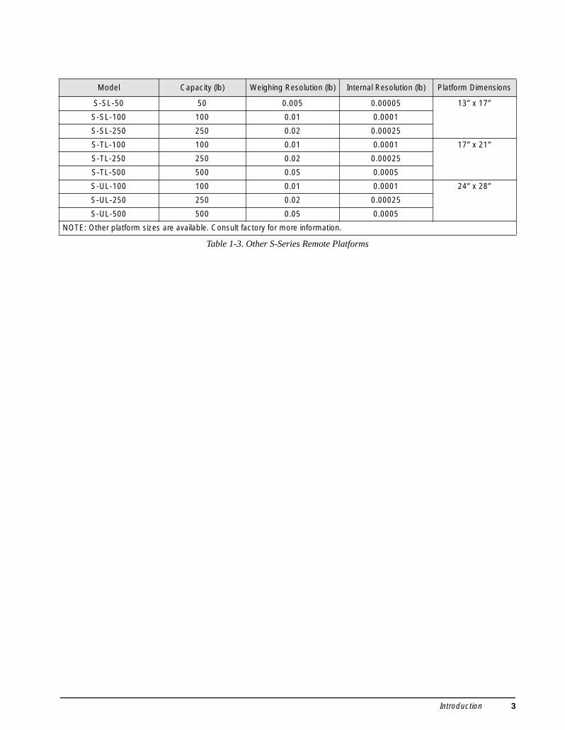
Model Capacity (lb) Weighing Resolution (lb) Internal Resolution (lb) Platform Dimensions
S-SL-50 50 0.005 0.00005 13” x 17”
S-SL-100 100 0.01 0.0001
S-SL-250 250 0.02 0.00025
S-TL-100 100 0.01 0.0001 17” x 21”
S-TL-250 250 0.02 0.00025
S-TL-500 500 0.05 0.0005
S-UL-100 100 0.01 0.0001 24” x 28”
S-UL-250 250 0.02 0.00025
S-UL-500 500 0.05 0.0005
NOTE: Other platform sizes are available. Consult factory for more information.
Table 1-3. Other S-Series Remote Platforms
Introduction 3
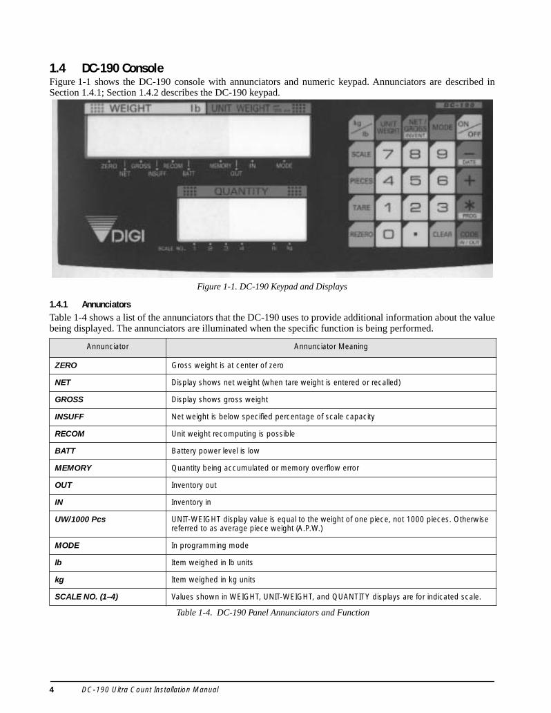
1.4 DC-190 ConsoleFigure 1-1 shows the DC-190 console with annunciators and numeric keypad. Annunciators are described inSection 1.4.1; Section 1.4.2 describes the DC-190 keypad.
Figure 1-1. DC-190 Keypad and Displays
1.4.1 AnnunciatorsTable 1-4 shows a list of the annunciators that the DC-190 uses to provide additional information about the valuebeing displayed. The annunciators are illuminated when the specific function is being performed.
Annunciator Annunciator Meaning
ZERO Gross weight is at center of zero
NET Display shows net weight (when tare weight is entered or recalled)
GROSS Display shows gross weight
INSUFF Net weight is below specified percentage of scale capacity
RECOM Unit weight recomputing is possible
BATT Battery power level is low
MEMORY Quantity being accumulated or memory overflow error
OUT Inventory out
IN Inventory in
UW/1000 Pcs UNIT-WEIGHT display value is equal to the weight of one piece, not 1000 pieces. Otherwise referred to as average piece weight (A.P.W.)
MODE In programming mode
lb Item weighed in lb units
kg Item weighed in kg units
SCALE NO. (1–4) Values shown in WEIGHT, UNIT-WEIGHT, and QUANTITY displays are for indicated scale.
Table 1-4. DC-190 Panel Annunciators and Function
4 DC-190 Ultra Count Installation Manual

1.4.2 DC-190 KeypadTable 1-5 lists the keys and key functions of the DC-190 Ultra Count keypad (see Figure 1-1 on page 4).
Key Description
through Used to enter numeric values. When using the scale, first enter a numeric value, then press the appropriate function key.
Used to enter numeric values containing a decimal point. NOTE: A numeric value must be entered before the decimal point. For example, .250 would be entered as 0.250. In normal mode, pressing the decimal key without entering a numeric value allows you to recall an item code from memory using the Teraoka Code (see Section 10.8 on page 58).
Clears keyed-in data from the display starting with the last digit entered or clears keyed-in data all at once (depends on SPEC 6, bit 2 setting). In normal weighing mode, can be used to clear the unit weight with a unit weight already entered. When using a recalled item code, press CLEAR to clear both the unit weight and the tare weight.
Switches display between pound (lb) and kilogram (kg). The scale powers up in the pound mode.
Used to cycle through Scales 1 through 4.
Used to compute unit weight by sampling. Press the PIECES key after placing a 10-piece sample on the platform, or after using the numeric keypad to enter the sample size. On multichannel units, the scale used must be selected.
Used to set and clear tare weights in the normal weighing mode.
Used to reset the scale to zero. Also used in conjunction with other keys to enter the maintenance mode. The REZERO key will not function when the scale is in motion.
Used to enter a known unit weight using the numeric keypad.
Switches between net weight and gross weight display modes. Also used as an inventory key (depends on SPEC 2, bit 0 setting).
Used to enter the program mode. The MODE annunciator is illuminated when the scale is in program mode and the WEIGHT display reads ProG. The quantity display shows the letter C and the number of item codes in memory.
Powers the scale on or off.
Used to operate the reduction function and to move between specification numbers (high to low) in SPEC setting mode. Also used to program part number in programming item codes. In programming mode, it can be used for viewing or setting date/time.
Used to operate the accumulation function and to move between specification numbers (low to high) in SPEC setting mode. Also used to program set points in programming item codes.
Used to store specification data in SPEC setting and program modes. Also used as a print key to transmit weight information.
Used to recall item code data and to switch between item code inventory IN and OUT modes. Also used to program commodity name in programming item codes.
Table 1-5. DC-190 Keypad Keys and Functional Descriptions
0 9
CLEAR
kg
lb
SCALE
PIECES
TARE
REZERO
UNITWEIGHT
NET/GROSSINVENT
MODE
ON
OFF
-DATE
+
PROG*CODEIN / OUT
Introduction 5

2.0 InstallationThis section describes the procedure for theinstallation and setup of the DC-190 counting scale.
2.1 Locking and UnlockingDo not turn scale upside down. Alwayswork with scale on its side! Damage tothe load cell can occur if the scale isturned upside down.
The DC-190 counting scale is delivered in a lockedposition to prevent damage to the load cells duringshipment.
To prevent damage to the load cells,scale must be locked prior to shipment.
The scale uses either one setscrew for the single-platformscale or two setscrews for the dual-platform scale. Thesetscrews are located on the bottom of the base and mustbe removed before the scale is put into service. Use thefollowing procedure to unlock your DC-190 countingscale.
1. Turn scale on side. Loosen locknut 1/4 turn (seeFigure 2-1).
Figure 2-1. Location of Load Cell Setscrews for Single- and Dual-Platform Scales
2. Remove load cell setscrew (see Figure 2-2)using the 2 mm hex wrench provided withscale.
NOTE: Keep locknut in theapproximate original position on thesetscrew to prevent damage to loadcell when reinstalling.
NOTE: Beginning in 2003, setscrews with slotted headswill replace the hex head types, and will no longer requirethe 2mm hex wrench for removal.
Figure 2-2. Setscrew Removal
3. Tape setscrews to the bottom of the scale orstore in a safe location for possible future use.
2.2 Setting UpPlace the scale on a solid, level surface away fromfans, breezes, and sources of electrical interference. Level the scale by turning the four adjustable legslocated on the bottom of the scale while referencingthe bubble level located on the back of the scale (seeFigure 2-3).
NOTE: To ensure greater scale stability, turn in allfour adjustable legs before leveling. Turn outadjustable legs to level as needed.
Figure 2-3. Bubble Level
Caution
Caution
SINGLE-PLATFORM LOAD CELL SETSCREW
DUAL-PLATFORM LOAD CELL SETSCREWS
LOAD CELL SETSCREW
BUBBLE LEVEL
6 DC-190 Ultra Count Installation Manual

2.3 Powering Up the DC-190The DC-190 can be operated either from an AC powersource or with an optional rechargeable battery pack(DC power). The DC power allows the unit to becompletely portable. Instructions for DC operation arecontained in Section 2.3.3.
2.3.1 AC Power SourceTo power-up the DC-190 using the AC power cord:
1. Connect female end of AC power cord(Figure 2-4) under scale base.
Figure 2-4. Location of AC Power Cord Receptacle and Load Cell Cable
2. Connect load cell cable from scale to CablePort 1 in the back of the keyboard(Figure 2-5).
3. Plug the AC power cord into a grounded 115VAC receptacle.
Figure 2-5. Scale Base Connector Ports
4. Press ON/OFF and allow scale to warm up for10 minutes. The display momentarily showsthe revision number, shows all digits from 0 to9 in a count-up mode, goes blank, shows all8s, and then enters normal weighing mode.
If the scale is connected to AC power while in theOFF condition, no warm-up is necessary.
NOTE: If the scale displays erratic data, it may becaused by a power transient. Turn the scale off andmomentarily unplug it from the wall outlet. Thenrestart by plugging the scale back in and pressing ON/OFF key. The scale will go through a display check;no warm up is needed.
2.3.2 DC Battery Pack Replacement/InstallationAn optional DC battery pack is available and may bepurchased from RLWS to ship with the scale orretrofit in the field. The battery pack is located in the bottom of the scalebase and partial disassembly is required to install orreplace it. Use the following procedure to install orreplace the battery pack.
To prevent load cell damage, reinstallsetscrews before replacing battery.
1. Unplug scale from power source.2. Remove scale platter.
3. Remove the four platform support screwsfrom the left-hand platform support assembly(shown in Figure 2-6). Remove the fourscrews from the right-hand platform supportassembly.
4. Remove both platform support assembliesand set aside.
NOTE: The single-platform scale has fourplatform support (spider) screws while thedual-platform scale has four screws for each of thetwo platform supports.
Figure 2-6. Removing Platter Support Screws and Platter Support on a Dual-Platform Scale
LOAD CELL CABLE
AC POWER CORD RECEPTACLE
CABLE PORT 2
CABLE PORT 1
Caution
REMOVE PLATFORM SUPPORT SCREWS(DUAL-PLATFORM INSTALLATION)
Installation 7

5. Place scale on side. Remove four top coverscrews (shown in Figure 2-7). Set scale onlegs and remove top cover.
Figure 2-7. Location of Top Cover Screws
6. Disconnect black (–) and red (+) electricalleads from battery (see Figure 2-8). Removeexisting DC battery pack. Attach red lead topositive (+) side of battery.
7. Attach black lead to negative (–) side ofbattery.
8. Place new DC battery pack in batterycompartment.
Figure 2-8. Battery Installation
9. Reassemble scale in the reverse order that itwas disassembled.
10. Remove setscrew to unlock scale beforeplacing the scale into service.
If the DC-190 scale is operated with thebattery pack removed, isolate thepositive (+) and negative (–) leads so
that they do not make contact with each other or any partof the scale frame or any sensitive electronic components.
2.3.3 DC Battery OperationTo power-up the DC-190 using the optional battery:
1. Remove AC power cord from bottom of scale.2. Turn battery switch to ON (located on the
bottom left-hand side of the scale base).
3. Press ON/OFF and allow scale to warm up for10 minutes. The display momentarily showsrevision number, shows all digits from 0 to 9in a count-up mode, goes blank, shows all 8s,and then enters normal weighing mode.
2.3.4 Battery ChargingA fully charged battery allows for approximately 4hours of continuous use. Refer to SPEC 1 (Power AutoOff function) for extended hours of use. It will takeapproximately 8 hours to fully recharge a battery thathas been completely dissipated. The console must beconnected to the base during the recharge cycle andthe AC power cord must be plugged in.NOTE: Do not store the scale without turning off thebattery power switch! When the battery switch is ON andthe AC is not connected, a low level battery current will floweven if the display is OFF. To prevent battery dischargewhen stored, turn the battery switch OFF whenever the unitis not in use.
2.4 Setting Time and DateYou can set the time and date printed on DC-190 printtickets. SPEC 5, bits 0 and 1 list three sequencevariations of year, month, day that are available toenter dates into the DC-190 counting scale. Printeddates always appear in mmddyy format. To set the date (month, date, and year) and time:
1. Press the MODE key.2. Press the –/DATE key. The displays shows the
date, day, and time.
3. Press the –/DATE key again. Enter month, day,year (mmddyy) on the keypad.
4. Press the –/DATE key. Enter the day (0=Mon,1=Tue…6=Sun.
5. Press the –/DATE key. Enter the time of dayusing the 24-hour clock. For example, enter1:35 p.m. as 1335.
6. Press the */PROG key to store the setting, orpress the –/DATE key to exit without savingtime and date.
TOP COVER SCREWS
BATTERY
POSITIVE (+) TERMINAL
NEGATIVE (-) TERMINAL
Caution
8 DC-190 Ultra Count Installation Manual
2.5 Installing Cable Strain ReliefTo prevent load cell or peripheral cable damage frombending and twisting, cable strain reliefs are used inthe back of the DC-190 keyboard. Each DC-190counting scale comes equipped with these rubberstrain reliefs and should be installed on initial scalesetup.
1. Remove the three 4 mm x 8 mm panheadscrews securing the bracket to the back of thekeyboard.
2. Remove rubber strain relief covering the two14-pin load cell cable ports. If any peripheraldevices are installed at this time, remove therubber strain relief covering the peripheralcable access ports.
3. Route load cell and/or any peripheral devicecables through opening in bracket. Connectcables to proper ports.
4. Install rubber strain relief over load cell/peripheral cables and position into cavity.Gently pull cables to take up any slack.
5. When rubber strain reliefs are securelymounted, reinstall bracket using the three 4mm x 8 mm panhead screws previouslyremoved.
2.6 Pole Mounting Instructions1. Disconnect AC power cord from the bottom
of the scale. Remove platform.2. Remove the plastic cover from the upper
mounting bracket.
NOTE: As a precaution, install load cell setscrew.
3. Turn scale on side.
4. Attach pole mount assembly to base usingthree 4 mm x 10 mm machine screws (shownin Figure 2-9).
Figure 2-9. Attach Pole Mount Assembly to Base
5. Route load cell and peripheral device cablesthrough center of pole mount assembly.
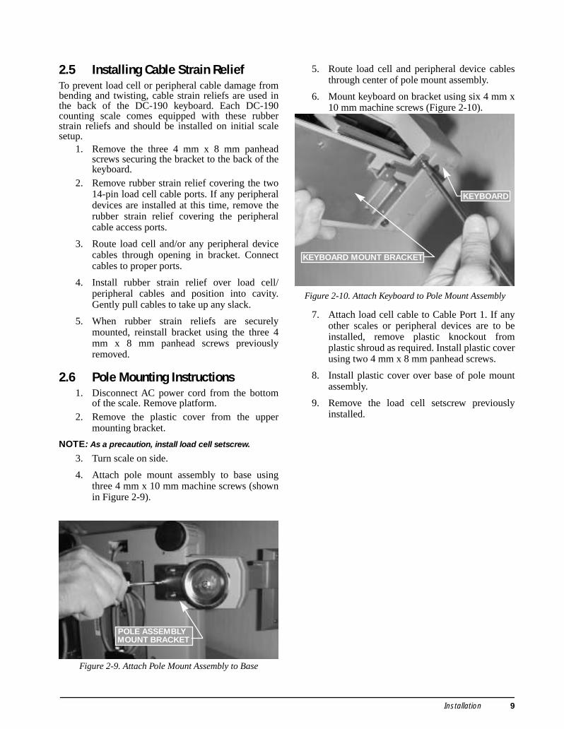
6. Mount keyboard on bracket using six 4 mm x10 mm machine screws (Figure 2-10).
Figure 2-10. Attach Keyboard to Pole Mount Assembly
7. Attach load cell cable to Cable Port 1. If anyother scales or peripheral devices are to beinstalled, remove plastic knockout fromplastic shroud as required. Install plastic coverusing two 4 mm x 8 mm panhead screws.
8. Install plastic cover over base of pole mountassembly.
9. Remove the load cell setscrew previouslyinstalled.
POLE ASSEMBLY MOUNT BRACKET
KEYBOARD MOUNT BRACKET
KEYBOARD
Installation 9
2.7 Load Cell ReplacementLoad cell replacement requires partial disassembly ofthe scale base. Sections 2.7.1 and 2.7.2 describe theprocedure for replacing in single- and dual-platformscales. On a dual-platform scale, there are two loadcell cables connected to a common power board. Loadcell replacement requires unsoldering and soldering ofload cell connections to the power board.
2.7.1 Single-Platform Load Cell Replacement
NOTE: Prior to replacing load cell, install load cellsetscrew as detailed in Section 2.1.
1. Disconnect AC power plug from bottom ofscale and remove platform.
2. Remove four platform support machinescrews and remove platform support.
3. Turn scale on side. Remove the four panheadmachine screws for top cover (Figure 2-7).Set scale on its four legs and remove topcover.
4. Disconnect DC power supply plug frompower board (Figure 2-11). Remove fourmachine screws securing board to chassis.
Figure 2-11. Disconnect DC Power Supply Plug and Remove the Four Power Supply Board Screws
5. Unsolder the five load cell wires at powerboard.
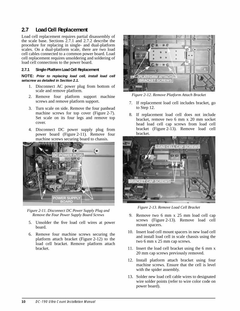
6. Remove four machine screws securing theplatform attach bracket (Figure 2-12) to theload cell bracket. Remove platform attachbracket.
Figure 2-12. Remove Platform Attach Bracket
7. If replacement load cell includes bracket, goto Step 12.
8. If replacement load cell does not includebracket, remove two 6 mm x 20 mm sockethead load cell cap screws from load cellbracket (Figure 2-13). Remove load cellbracket.
Figure 2-13. Remove Load Cell Bracket
9. Remove two 6 mm x 25 mm load cell capscrews (Figure 2-13). Remove load cellmount spacers.
10. Insert load cell mount spacers in new load celland install load cell in scale chassis using thetwo 6 mm x 25 mm cap screws.
11. Insert the load cell bracket using the 6 mm x20 mm cap screws previously removed.
12. Install platform attach bracket using fourmachine screws. Ensure that the cell is levelwith the spider assembly.
13. Solder new load cell cable wires to designatedwire solder points (refer to wire color code onpower board).
DC POWER PLUG
POWER SUPPLYBOARD
PLATFORM ATTACH BRACKET SCREWS
BRACKET CAP SCREWS
LOAD CELL CAP SCREWS
10 DC-190 Ultra Count Installation Manual

14. Install power board using the four machinescrews previously removed. Route load cellcable under power board as shown inFigure 2-11. Reinstall ground terminal underone machine screw head.
15. Connect DC inlet power supply.
16. Replace scale base cover and platformsupport brackets in the reverse order ofdisassembly.
17. Remove load cell setscrew before putting thescale back into service.Recalibrate bothscales. See Section 5.0 on page 25.
18. Recalibrate scale (see Section 5.0 onpage 25).
2.7.2 Dual-Platform Load Cell Replacement
NOTE: Prior to replacing load cell, install load cellsetscrews as detailed in Section 2.1.
1. Remove both platforms. Disconnect ACpower cord from bottom of scale.
2. Remove four platform support machinescrews from each platform and remove bothplatform supports.
3. Turn scale on side. Remove the four panheadmachine screws for top cover (Figure 2-7).Set scale on its four legs and remove topcover.
4. Disconnect DC power supply plug frompower board (Figure 2-11). Remove fourmachine screws securing board to chassis.
The following procedure shows removal of one of thetwo load cells. General instructions are applicable toeither load cell.
5. Unsolder the five load cell wires at powerboard.
6. Remove four machine screws securing theplatform attach bracket (Figure 2-14) to theload cell bracket. Remove platform attachbracket.
Figure 2-14. Remove Platform Attach Bracket
7. If replacement load cell includes bracket, goto Step 12.
8. If replacement load cell does not includebracket, remove two load cell cap screws fromload cell bracket (Figure 2-15). Remove loadcell bracket.
Figure 2-15. Remove Load Cell Bracket
9. Remove two load cell cap screws. Removeload cell mount spacers.
10. Insert load cell mount spacers in new load celland install load cell in scale chassis using thetwo cap screws.
11. Insert the load cell bracket using the capscrews previously removed.
12. Install platform attach brackets using fourmachine screws. Ensure that the cells are levelwith the spider assembly.
13. Solder new load cell cable wires to designatedwire solder points (refer to wire color code onpower board).
14. Install power board using the four machinescrews previously removed. Route load cellcable under power board as shown inFigure 2-11. Reinstall ground terminal underone machine screw head.
15. Connect DC inlet power supply.
16. Replace scale base cover and platformsupport brackets in the reverse order ofdisassembly.
17. Remove load cell setscrews before putting thescale back into service.
18. Recalibrate both scales. See Section 5.0 onpage 25.
PLATFORM ATTACH BRACKETS
LOAD CELL BRACKET
Installation 11
3.0 Scale SetupThis section provides information about attaching scales and serial devices to the DC-190. Information presenteddescribes both physical connections and values that must be specified when configuring the DC-190 (seeSection 4.0). If you know what scales and serial devices will be connected to the DC-190, you can use the SPECCode Worksheets Section 10.1 on page 50 to record these values for later configuration.
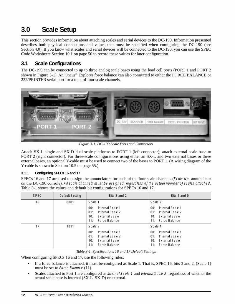
3.1 Scale ConfigurationsThe DC-190 can be connected to up to three analog scale bases using the load cell ports (PORT 1 and PORT 2shown in Figure 3-1). An Ohaus® Explorer force balance can also connected to either the FORCE BALANCE or232/PRINTER serial port for a total of four scale channels.
Figure 3-1. DC-190 Scale Ports and Connectors
Attach SX-L single and SX-D dual scale platforms to PORT 1 (left connector); attach external scale base toPORT 2 (right connector). For three-scale configurations using either an SX-L and two external bases or threeexternal bases, an optional Y-cable must be used to connect two of the bases to PORT 1. (A wiring diagram of theY-cable is shown in Section 10.5 on page 55.)
3.1.1 Configuring SPECs 16 and 17SPECs 16 and 17 are used to assign the annunciators for each of the four scale channels (Scale No. annunciatoron the DC-190 console). All scale channels must be assigned, regardless of the actual number of scales attached.Table 3-1 shows the values and default bit configurations for SPECs 16 and 17.
When configuring SPECs 16 and 17, use the following rules:
• If a force balance is attached, it must be configured as Scale 1. That is, SPEC 16, bits 3 and 2, (Scale 1)must be set to Force Balance (11).
• Scales attached to Port 1 are configured as Internal Scale 1 and Internal Scale 2, regardless of whether theactual scale base is internal (SX-L, SX-D) or external.
SPEC Default Setting Bits 3 and 2 Bits 1 and 0
16 0001 Scale 1
00: Internal Scale 101: Internal Scale 210: External Scale11: Force Balance
Scale 2
00: Internal Scale 101: Internal Scale 210: External Scale11: Force Balance
17 1011 Scale 3
00: Internal Scale 101: Internal Scale 210: External Scale11: Force Balance
Scale 4
00: Internal Scale 101: Internal Scale 210: External Scale11: Force Balance
Table 3-1. Specifications 16 and 17 Default Settings
PORT 1 PORT 2
12 DC-190 Ultra Count Installation Manual
• The scale attached to Port 2 is configured as External Scale.• All Scales (1–4) must be configured, and the value of each bit pair must be unique: each Scale (1–4)
must have a different value. For example, do not attempt to configure two or more scales as ExternalScale; doing so will cause the DC-190 to lock up with an all 888888s display. See Section 10.7 onpage 57 for information about clearing this error condition.
SPECs 16 and 17 do not turn on the additional scales; by default, only one scale is enabled. Scales 2 and 3 areturned on and off using SPEC 25, bit 1 (Scale Type, single or dual) and SPEC 32, bit 0 (Scale Connected to Port2). The force balance is turned on and off in SPEC 8, bit 3 (Force Balance on RS-232C port); the port used by theforce balance is selected in SPEC 13, bits 2, 1, and 0 (RS-232 Connectors).
When adding a second or third platform to the DC-190, plug in the remote scale (ordummy plug) before connecting AC power to the DC-190 and before enabling the addedscales in the configuration SPECs. Do not unplug a remote scale while the DC-190 ispowered on.
3.1.2 Scale Configurations, No Force Balance AttachedTable 3-2 lists several scale configurations for single, dual, and console-only models of the DC-190 with no forcebalance attached. Required values for each configuration are shown for SPECs 16 and 17 (including Scale No.assignments), SPEC 25 (bit 1), and SPEC 32 (bit 0). Because no force balance is attached, SPEC 8, bit 3, must beset to 0 for all listed configurations.
DC-190 Model PORT 1 Connector PORT 2 Connector SPEC 16 SPEC17 SPEC 25 SPEC 32
S-XL platform (SCALE 1) — 0001 1011 xx0x xxx0
S-XL platform (SCALE 1) External scale (SCALE 2)See note below
0010 0111 xx0x xxx1
S-XL platform (SCALE 1)External scale (SCALE 2)
Requires Y-cable
External scale (SCALE 3) 0001 1011 xx1x xxx1
S-XD, small platform (SCALE 1)S-XD, large platform (SCALE 2)
— 0001 1011 xx1x xxx0
S-XD, small platform (SCALE 1)S-XD, large platform (SCALE 2)
External scale (SCALE 3) 0001 1011 xx1x xxx1
External scale (SCALE 1) — 0001 1011 xx0x xxx0
External scale (SCALE 1) External scale (SCALE 2)See note below
0010 0111 xx0x xxx1
External scale (SCALE 1)External scale (SCALE 2)
Requires Y-cable)
External scale (SCALE 3) 0001 1011 xx1x xxx1
NOTES: • SPEC 8, bit 3, must be set to 0 (0xxx) if no force balance is connected to the DC-190. Setting this bit to 1 with no force
balance connected will cause the scale to lock up.• Console-only configurations require external AC adapter.• If an external scale is attached to PORT 2 and only one scale is attached to the PORT 1 connector, the external scale is
configured using Scale 3 parameters (SPECs 33, 36, and 37).
Table 3-2. DC-190 Scale Configurations (No Force Balance Connected)
Caution
Scale Setup 13

3.1.3 Scale Configurations, Including Force BalanceTable 3-2 lists several scale configurations for single, dual, and console-only models of the DC-190 with a forcebalance attached. Required values for each configuration are shown for SPECs 16 and 17 (including Scale No.assignments), SPEC 25 (bit 1), and SPEC 32 (bit 0). Because a force balance is attached, SPEC 8, bit 3, must beset to 1 for all listed configurations.
3.2 Serial ConfigurationsThe DC-190 provides three serial communications ports (see Figure 3-1 on page 12). Table 3-4 lists the ports,connector type, type of serial data transmitted, and the SPEC numbers used to set the serial port characteristics,including data length, baud rate, stop bits, and parity bits for the port.
Serial data transmitted or received on these ports can be any of the following types:• Continuous input from an Ohaus Explorer force balance• Printer output, with fixed format print drivers for various ticket, tape, and label printers (see description
of SPECs 3 and 11 in Section 4.2 on page 18)• Comma-delimited PC data (Program mode only), with selectable fields (see Section 4.4 on page 24)
SPEC 13, bits 2, 1, and 0, determine the type of device attached to the DIN-8 (FORCE BALANCE) and D-sub(232C/PRINTER) serial ports. See Section 3.2.1 on page 15.
NOTE: When attaching peripheral devices to the DC-190, connect all devices with the scale powered offand unplugged. (Pressing the ON/OFF button does not completely power-down the scale.) Once devicesare attached, reconnect power to the scale and press the ON/OFF button.
DC-190 Model PORT 1 Connector PORT 2 Connector SPEC 16 SPEC17 SPEC 25 SPEC 32
S-XL platform (SCALE 2) — 1100 0110 xx0x xxx0
S-XL platform (SCALE 2) External scale (SCALE 3) 1100 1001 xx0x xxx1
S-XL platform (SCALE 2)External scale (SCALE 3)
Requires Y-cable
External scale (SCALE 4) 1100 0110 xx1x xxx1
S-XD, small platform (SCALE 2)S-XD, large platform (SCALE 3)
— 1100 0110 xx1x xxx0
S-XD, small platform (SCALE 2)S-XD, large platform (SCALE 3)
External scale (SCALE 4) 1100 0110 xx1x xxx1
External scale (SCALE 2) — 1100 0110 xx0x xxx0
External scale (SCALE 2) External scale (SCALE 3) 1100 1001 xx0x xxx1
External scale (SCALE 2)External scale (SCALE 3)
Requires Y-cable)
External scale (SCALE 4) 1100 0110 xx1x xxx1
NOTES: • Any attached force balance must be configured as SCALE 1 (see SPECs 16 and 17 above).• SPEC 8, bit 3, must be set to 1 (1xxx) to enable the force balance.• Console-only configurations require external AC adapter.
Table 3-3. DC-190 Scale Configurations (Force Balance Connected)
Port Label Connector Type Serial Data/Device Types Serial Port Specifications
SCANNER 8-pin DIN Bar code pens and scanners SPECs 14 and 15
FORCE BALANCE 8-pin DIN Force balance inputPrinter outputPC output
SPECs 8 and 9SPECs 10 and 11232C/PRINTER 9-pin D-sub
Table 3-4. DC-190 Serial Ports
14 DC-190 Ultra Count Installation Manual

3.2.1 Configuring SPEC 13SPEC 13 determines the type of data sent or received on the DIN-8 (FORCE BALANCE) and D-sub (232C/PRINTER) serial ports. Table 3-5 shows the values that can be assigned to SPEC 13.
Depending on the value specified for SPEC 13, the characteristics of each serial port may be controlled bySPECs 8 and 9 or by SPECs 10 and 11:
• If a force balance is attached (or if the port is assigned as a Force Balance in SPEC 13), the portcharacteristics are set by SPECs 8 and 9. SPEC 8, bit 3, must be set to 1 if a force balance is attached.
• If a printer is attached (or if the port is assigned as a Printer port in SPEC 13), the port characteristics areset by SPECs 10 and 11. SPEC 10, bit 3, must be set to 1 if a printer is attached to either port.
• If a PC is attached (or if the port is assigned as a PC port in SPEC 13), the port characteristics are set bywhichever pair of SPECs (8 and 9 or 10 and 11) are not claimed by the other port. The port designatedfor Force Balance or Printer takes priority over the PC port.
NOTE: SPEC 8, bit 3 (Force Balance Attached) and SPEC 10, bit 3, (Printer Attached) enable their associatedserial port to receive continuous data from a force balance (SPEC 8) or to send printer data. Do not set these bitsto 1 (on) unless that device type is actually attached and powered on. Enabling these bits without the deviceattached will cause the scale to lock up with an all 888888s display. See Section 10.7 on page 57 for informationabout clearing this error condition.
The default value of SPEC 13, x001, sets up the DC-190 for a force balance on the DIN-8 port and a printer onthe D-sub port. Both SPEC 8, bit 3, and SPEC 10, bit 3, are set to 0 (off) by default: any attached devices must beenabled in SPEC configuration before they can be used.
SPEC 13 ValueDevice Type Attached to
FORCE BALANCE (DIN-8) PortDevice Type Attached to
232C/PRINTER (D-Sub) Port
x000 Force Balance or no device Printer
x001 Printer Force Balance or no device
x010 PC Printer
x011 Printer PC
x100 Force Balance or no device PC
x101 PC Force Balance or no device
Table 3-5. SPEC 13 Values, Bits 2, 1, and 0
Scale Setup 15

3.2.2 FORCE BALANCE (DIN-8) and 232C/PRINTER (D-Sub) Port ConnectionsTable 3-6 shows possible serial device configurations for each valid setting of SPEC 13, including the SPECnumbers used to set serial port characteristics in each listed configuration.
NOTE: The DC-190 can also be configured for two printers, using SPEC 13 values of x010 or x011. The printerdrivers and commands sent to each port are set using SPEC 3 and SPEC 11, bit 2. See Section 4.2 on page 18 formore information.
3.2.3 SCANNER Port ConnectionsThe SCANNER port is a dedicated port, used only for barcode pens or scanners. The port is enabled bysetting SPEC 14, bit 3, to 1. SPECs 14 and 15 set the data length, baud rate, stop bits, and parity bits forthe port. See Section 4.2 on page 18 for more information about SCANNER port specifications.
Section 10.10 on page 60 provides scanner setup information for the PSC QuickScan 6000 scanner.
SPEC 13
FORCE BALANCE PORT (DIN-8) 232C/PRINTER PORT (D-SUB)
Device Type Port Control Specs Device Type Port Control Specs
x000 or NONE
SPEC 8 = 1xxxSPEC 9 = x1xx
See Note 1
SPEC 10 = 1xxxSPEC 11 = xxxx
See Note 2
x001 SPEC 10 = 1xxxSPEC 11 = xxxx
See Note 2
or NONESPEC 8 = 1xxxSPEC 9 = x1xx
See Note 1
x010 SPEC 8 = 0xxxSPEC 9 = x1xx
SPEC 10 = 1xxxSPEC 11 = xxxx
See Note 2
x011 SPEC 10 = 1xxxSPEC 11 = xxxx
See Note 2
SPEC 8 = 0xxxSPEC 9 = x1xx
x100 or NONE
SPEC 8 = 1xxxSPEC 9 = x1xx
See Note 1
SPEC 10 = 1xxxSPEC 11 = xxxx
x101 SPEC 10 = 1xxxSPEC 11 = xxxx or NONE
SPEC 8 = 1xxxSPEC 9 = x1xx
See Note 1
NOTES:
1. SPEC 8, bit 3, must be set to 0 (0xxx) if no force balance is connected to the DC-190. Setting this bit to 1 with no force balance connected will cause the scale to lock up.
2. SPEC 10, bit 3, must be set to 0 (0xxx) if no printer is connected to the DC-190. Setting this bit to 1 with no printer connected will cause the scale to lock up.
Table 3-6. SPEC 13 Settings and Controlling Port Specifications for Serial Device Connections
16 DC-190 Ultra Count Installation Manual

4.0 Configuration SettingsThis section presents the setup and configuration of the DC-190 counting scale to be used specifically bydistributors and service technicians. These configuration settings customize the counting scale for individualapplications.
Setting configuration allows you to easily modify the functionality of your DC-190. Use the tables in this sectionto view the options you can modify. For example, to enable the Unit Weight Auto-Recomputing function, go toSPEC 5 in the specification table. Go across the row and see that bit 2 controls this function. The default forSPEC 5 is 1011, which means that the Unit Weight Auto-Recomputing function is turned off. To turn it on,change the bit string to 1111.
The following tables list the DC-190 specifications and their corresponding default values. Each specification(SPEC) consist of four bits (bits 3 through 0) and represent various settings or selections.
• SPECs 00–19 (Table 4-1) are customer specifications and use the 141 access code • SPECs 20–39 (Table 4-2 on page 21) are weight and measurement specifications and use the 142 access
code• SPECs 40–59 use the 143 access code• SPECs 40–45 are RS-232 specifications (see Table 4-3 on page 24)• SPECs 46–59 are not used. These SPECs must be set to 0000.
NOTE: Worksheets for each of the access code groups are included in Section 10.1 on page 50. These worksheetscan be used to record and plan configuration settings for each SPEC.
4.1 Configuration ProcedureThe general procedure for setting SPEC codes is as follows:
1. Press and hold the REZERO key then use the numeric keypad to enter the access code number (141, 142,or 143). The number of the first SPEC code for that access code appears in the WEIGHT display; thevalue of the four bits for that SPEC appear in QUANTITY display. Bit 3 is the left digit in QUANTITY dis-play.
2. Press the + key to move up through each specification until the desired specification is obtained. (Pressthe – key to move down through each specification.) The + and – keys wrap from the first SPEC of eachaccess code to the last. For example: with SPEC 0 displayed (SPC00), pressing the + key displays SPEC1; pressing the – key wraps to SPEC 19, the last of the 141 access code SPECs.
3. Enter the new bit string (four bits required), starting with bit 3. Press + or – to store bit settings intotemporary memory.
4. Repeat Steps 2 and 3 until all specifications are changed.
5. Press the * key to store the new values in RAM and exit configuration mode.
6. Press MODE to return to weighing mode.
7. Power scale off, then on, to permanently update the changed SPECs and initialize the scale with the newsettings.
Configuration Settings 17
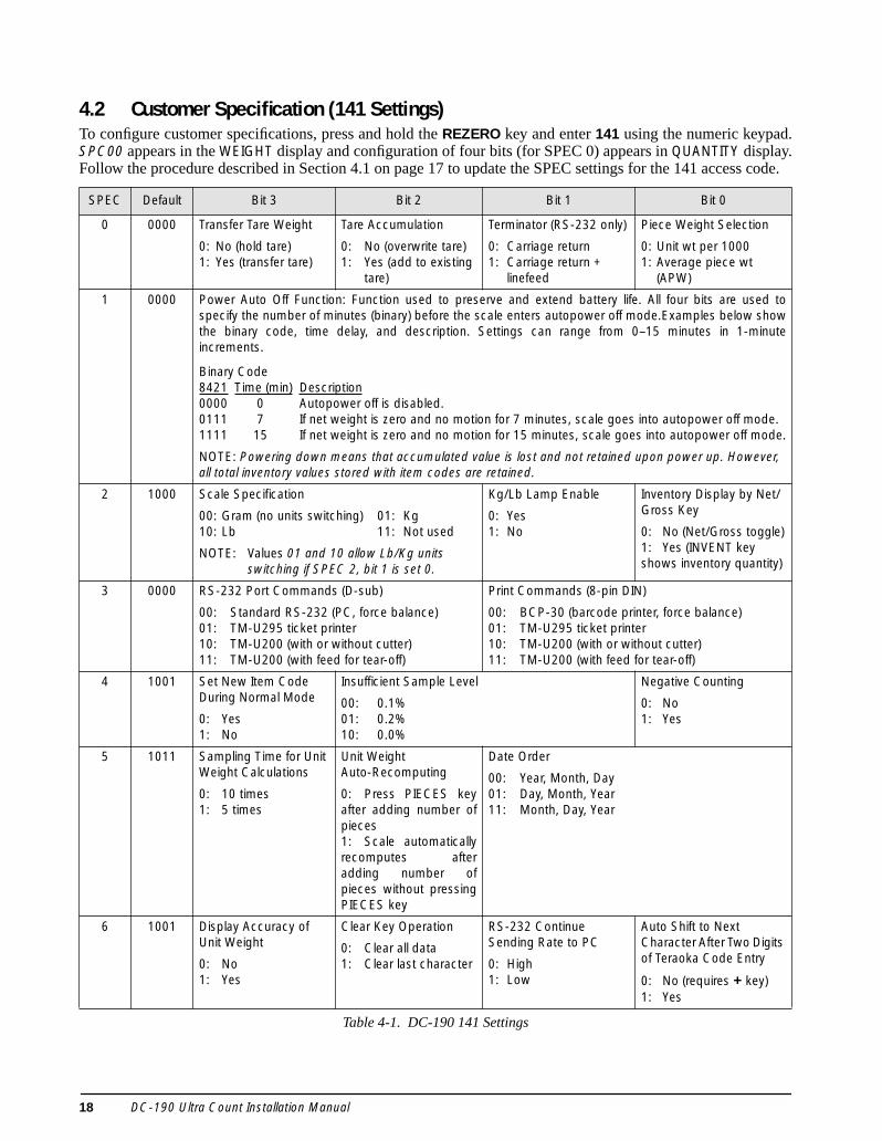
4.2 Customer Specification (141 Settings)To configure customer specifications, press and hold the REZERO key and enter 141 using the numeric keypad.SPC00 appears in the WEIGHT display and configuration of four bits (for SPEC 0) appears in QUANTITY display.Follow the procedure described in Section 4.1 on page 17 to update the SPEC settings for the 141 access code.
SPEC Default Bit 3 Bit 2 Bit 1 Bit 0
0 0000 Transfer Tare Weight
0: No (hold tare)1: Yes (transfer tare)
Tare Accumulation
0: No (overwrite tare)1: Yes (add to existing
tare)
Terminator (RS-232 only)
0: Carriage return1: Carriage return +
linefeed
Piece Weight Selection
0: Unit wt per 10001: Average piece wt
(APW)
1 0000 Power Auto Off Function: Function used to preserve and extend battery life. All four bits are used tospecify the number of minutes (binary) before the scale enters autopower off mode.Examples below showthe binary code, time delay, and description. Settings can range from 0–15 minutes in 1-minuteincrements.
Binary Code8421 Time (min) Description0000 0 Autopower off is disabled.0111 7 If net weight is zero and no motion for 7 minutes, scale goes into autopower off mode. 1111 15 If net weight is zero and no motion for 15 minutes, scale goes into autopower off mode.
NOTE: Powering down means that accumulated value is lost and not retained upon power up. However, all total inventory values stored with item codes are retained.
2 1000 Scale Specification
00: Gram (no units switching) 01: Kg 10: Lb 11: Not used
NOTE: Values 01 and 10 allow Lb/Kg units switching if SPEC 2, bit 1 is set 0.
Kg/Lb Lamp Enable
0: Yes1: No
Inventory Display by Net/Gross Key
0: No (Net/Gross toggle)1: Yes (INVENT key shows inventory quantity)
3 0000 RS-232 Port Commands (D-sub)
00: Standard RS-232 (PC, force balance)01: TM-U295 ticket printer10: TM-U200 (with or without cutter)11: TM-U200 (with feed for tear-off)
Print Commands (8-pin DIN)
00: BCP-30 (barcode printer, force balance)01: TM-U295 ticket printer10: TM-U200 (with or without cutter)11: TM-U200 (with feed for tear-off)
4 1001 Set New Item Code During Normal Mode
0: Yes1: No
Insufficient Sample Level
00: 0.1%01: 0.2%10: 0.0%
Negative Counting
0: No1: Yes
5 1011 Sampling Time for Unit Weight Calculations
0: 10 times1: 5 times
Unit Weight Auto-Recomputing
0: Press PIECES keyafter adding number ofpieces1: Scale automaticallyrecomputes afteradding number ofpieces without pressingPIECES key
Date Order
00: Year, Month, Day01: Day, Month, Year11: Month, Day, Year
6 1001 Display Accuracy of Unit Weight
0: No1: Yes
Clear Key Operation
0: Clear all data1: Clear last character
RS-232 Continue Sending Rate to PC
0: High 1: Low
Auto Shift to Next Character After Two Digits of Teraoka Code Entry
0: No (requires + key)1: Yes
Table 4-1. DC-190 141 Settings
18 DC-190 Ultra Count Installation Manual

7 0000 Setpoint Buzzer
0: Yes1: No
Setpoint Latch
0: Latching1: Non-latching
Setpoint Type
00: % Quantity 01: % Weight10: Quantity 11: Weight
NOTE: See Section 3.2.2 on page 16 for more information about configuring SPECs 8–11
8 0010 Force Balance Attached
0: No1: Yes
RS-232C Data Length
0: 7 bits1: 8 bits
RS-232C Baud Rate
00: 1200 01: 240010: 4800 11: 9600
9 0111 RS-232C Stop Bits
0: 1 bit1: 2 bits
Force Balance Type
0: Not used1: Ohaus Explorer
RS-232C Parity Bit
00: No 01: Odd10: Not used 11: Even
10 0111 Printer or PC Attached
0: No1: Yes
RS-232C Data Length 0:7 bits
1: 8 bits
RS-232C Baud Rate
00: 1200 01: 240010: 4800 11: 9600
11 0100 RS-232C Stop Bits
0: 1 bit1: 2 bits
Printer Driver
0: Eltron printer driver or comma-delimited file
1: BCP30, BCP-300, or Epson printer
RS-232 Parity Bit
00: No 01: Odd10: Not used 11: Even
12 1000 RS-232 (PC/PRN) Output
00: Not available01: When counting condition (PC)10: By * key (printer and PC)11: In both cases
Eltron Format
0: Eltron fixed label format (also for BCP30, BCP300)
1: Custom download format
RS-232C PC Data Sent with Header Codes
0: Yes1: No
NOTE: See Section 3.2.1 on page 15 for more information about configuring SPEC 13
13 0001 RS-232 PC Header
0: Header codes1: Field titles
RS-232 Connectors
If only one RS-232 device (printer or PC) is connected to the scale, select one of the four settings below:
DIN-8 (FORCE BALANCE) D-Sub (232C/PRINTER) 000: Force Balance (SPEC 8, 9 Printer (SPEC 10, 11) 001: Printer (SPEC 10, 11) Force Balance (SPEC 8, 9) 100: Force Balance (SPEC 8, 9 PC (SPEC 10, 11) 101: PC (SPEC 10, 11) Force Balance (SPEC 8, 9)
If two RS-232 devices (printer and PC) are connected to the scale, select one of the two settings below:
DIN-8 (FORCE BALANCE) D-Sub (232C/PRINTER) 010: PC (SPEC 8, 9) Printer (SPEC 10, 11) 011: Printer (SPEC 10, 11 PC (SPEC 8, 9)
NOTE: See Section 10.10 on page 60 for PSC QuickScan 6000 scanner setup information (SPECs 14 and 15).
14 1010 RS-232C Connection (Barcode pen)0: No1: Yes
RS-232C Data Length (Barcode pen)0: 7 Bits1: 8 Bits
RS-232C Baud Rate (Barcode pen)00: 1200 01: 240010: 4800 11: 9600
SPEC Default Bit 3 Bit 2 Bit 1 Bit 0
Table 4-1. DC-190 141 Settings (Continued)
Configuration Settings 19

15 0011 RS-232C Stop Bits (Barcode pen)
0: 1 Bit1: 2 Bits
RS-232C with Header (Barcode pen)
0: Yes (first character recognized as header)
1: No (every bar code treated as ID code)
RS-232C Parity Bit (Barcode pen)
00: No 01: Odd10: Not used 11: Even
NOTE: All scale channels must be assigned in SPECs 16 and 17, regardless of the actual number of scales attached. See Section 3.1.1 on page 12 for detailed information about configuring these SPECs.
16 0001 Scale 1
00: Internal Scale 101: Internal Scale 210: External Scale11: Force Balance
Scale 2
00: Internal Scale 101: Internal Scale 210: External Scale11: Force Balance
17 1011 Scale 3
00: Internal Scale 101: Internal Scale 210: External Scale11: Force Balance
Scale 4
00: Internal Scale 101: Internal Scale 210: External Scale11: Force Balance
18 0000 Setpoint TTL Output
0: Active low (0V)1: Active high (+5V)
Number of Setpoints. Values for 3–6 setpoints are valid only if SPEC 7, bits 0 and 1, are set to 10 or 11 (Quantity or Weight).
000: 2 setpoints001: 3 setpoints010: 4 setpoints011: 5 setpoints100: 6 setpoints
19 1000 Display “not F” Message for Items not Stored in Memory
0: Yes1: No
Link to IMS (US version)
0: No1: Yes
Type of Force Balance (Japan version only)
0: SHG-3001: HR-60
Print when Pressing + or – Key in Add Mode
0: Yes1: No (print only with *)
SPEC Default Bit 3 Bit 2 Bit 1 Bit 0
Table 4-1. DC-190 141 Settings (Continued)
20 DC-190 Ultra Count Installation Manual
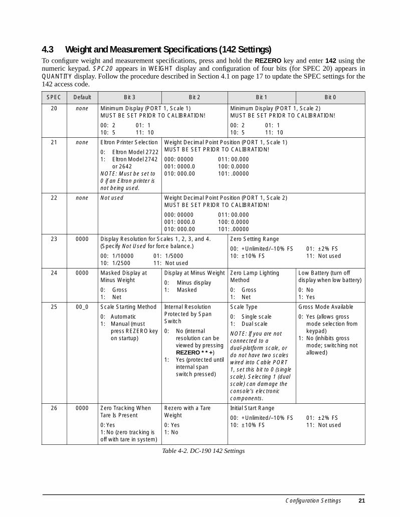
4.3 Weight and Measurement Specifications (142 Settings)To configure weight and measurement specifications, press and hold the REZERO key and enter 142 using thenumeric keypad. SPC20 appears in WEIGHT display and configuration of four bits (for SPEC 20) appears inQUANTITY display. Follow the procedure described in Section 4.1 on page 17 to update the SPEC settings for the142 access code.
SPEC Default Bit 3 Bit 2 Bit 1 Bit 0
20 none Minimum Display (PORT 1, Scale 1)MUST BE SET PRIOR TO CALIBRATION!
00: 2 01: 110: 5 11: 10
Minimum Display (PORT 1, Scale 2)MUST BE SET PRIOR TO CALIBRATION!
00: 2 01: 110: 5 11: 10
21 none Eltron Printer Selection
0: Eltron Model 27221: Eltron Model 2742
or 2642NOTE: Must be set to 0 if an Eltron printer is not being used.
Weight Decimal Point Position (PORT 1, Scale 1)MUST BE SET PRIOR TO CALIBRATION!
000: 00000 011: 00.000001: 0000.0 100: 0.0000010: 000.00 101: .00000
22 none Not used Weight Decimal Point Position (PORT 1, Scale 2)MUST BE SET PRIOR TO CALIBRATION!
000: 00000 011: 00.000001: 0000.0 100: 0.0000010: 000.00 101: .00000
23 0000 Display Resolution for Scales 1, 2, 3, and 4. (Specify Not Used for force balance.)
00: 1/10000 01: 1/500010: 1/2500 11: Not used
Zero Setting Range
00: +Unlimited/–10% FS 01: ±2% FS10: ±10% FS 11: Not used
24 0000 Masked Display at Minus Weight
0: Gross1: Net
Display at Minus Weight
0: Minus display1: Masked
Zero Lamp Lighting Method
0: Gross1: Net
Low Battery (turn off display when low battery)
0: No1: Yes
25 00_0 Scale Starting Method
0: Automatic1: Manual (must
press REZERO key on startup)
Internal Resolution Protected by Span Switch
0: No (internal resolution can be viewed by pressing REZERO * * +)
1: Yes (protected until internal span switch pressed)
Scale Type
0: Single scale1: Dual scale
NOTE: If you are not connected to a dual-platform scale, or do not have two scales wired into Cable PORT 1, set this bit to 0 (single scale). Selecting 1 (dual scale) can damage the console’s electronic components.
Gross Mode Available
0: Yes (allows gross mode selection from keypad)
1: No (inhibits gross mode; switching not allowed)
26 0000 Zero Tracking When Tare Is Present
0: Yes1: No (zero tracking is off with tare in system)
Rezero with a Tare Weight
0: Yes1: No
Initial Start Range
00: +Unlimited/–10% FS 01: ±2% FS10: ±10% FS 11: Not used
Table 4-2. DC-190 142 Settings
Configuration Settings 21

27 0100 Comma Display
0: No1: Yes
Keypad Entry of Tare
0: No1: Yes
Tare Range
00: 100% FS 01: 50% FS10: 5% FS 11: Not used
28 0000 Auto Tare Clear when Rezeroed
0: No1: Yes (REZERO
clears tare value)
Automatic Unit Weight Clear Condition
00: Over net 5d and gross 21d, weight stable01: Greater than or equal to net 1d, weight stable10: Greater than or equal to net 1d, quantity > 0,
weight stable
Automatic Unit Weight Clear
0: No1: Yes
29 0000 Digital Tare Rounding
0: Tare exactly1: Round to nearest
increment
Tare Value Exchange with TARE key
0: Yes (allow tare addition/subtraction)
1: No
Tare Addition
0:Yes (new tare weight added to existing tare)
1:No
Tare Subtraction
0: Yes (new tare weight subtracted from existing tare)
1: No
30 none Load Cell Sensitivity Selection (mV/V)—PORT 1, Scale 1Load cell sensitivity is automatically set at calibration. Manual adjustments can be made to reduce noise.
Spec Min Max0000: 3.46 4.000001: 3.00 3.460010: 2.59 3.000011: 2.25 2.59
Spec Min Max0100: 1.95 2.250101: 1.69 1.950110: 1.46 1.690111: 1.27 1.46
Spec Min Max1000: 1.09 1.271001: 0.95 1.091010: 0.82 0.951011: 0.71 0.82
Spec Min Max1100: 0.61 0.711101: 0.53 0.911110: 0.46 0.531111: 0.40 0.46
31 none Load Cell Sensitivity Selection (mV/V)—PORT 1, Scale 2Load cell sensitivity is automatically set at calibration. Manual adjustments can be made to reduce noise.
Spec Min Max0000: 3.46 4.000001: 3.00 3.460010: 2.59 3.000011: 2.25 2.59
Spec Min Max0100: 1.95 2.250101: 1.69 1.950110: 1.46 1.690111: 1.27 1.46
Spec Min Max1000: 1.09 1.271001: 0.95 1.091010: 0.82 0.951011: 0.71 0.82
Spec Min Max1100: 0.61 0.711101: 0.53 0.911110: 0.46 0.531111: 0.40 0.46
32 1010 Calibration Mode Protected by Span Switch
0: Yes (span switch must be pressed before calibration)
1: No
Low Battery Annunciator Enabled
0: Yes1: No
Auto Exit from Part Accumulation and Reduction Mode
0:No (must press CLEAR to perform another accumulation)
1:Yes (exits to counting mode after three seconds)
Scale Connected to PORT 2
0: No1: Yes
CAUTION: If you are not connecting a scale to this connector, select 0. Selecting 1 can damage the console’s electronic components.
33 0___ Over Weight Mask at:
0: +1d1: +9d
Weight Decimal Point Position (PORT 2, Scale 2 or 3)MUST BE SET PRIOR TO CALIBRATION!
000: 00000 011: 00.000001: 0000.0 100: 0.0000010: 000.00 101: 0.00000
34 0000 Not used A/D Output (PORT 1, Scale 1)
0: For std/normal load cell (≤ 18 mV)
1: For abnormal load cell with too large offset (> 18mV)
A/D Filtering (PORT 1, Scale 1)
00: Normal01: Protect from small vibration/fast change in
display10: Protect from medium vibration11: Protect from large vibration, slow change in
display
SPEC Default Bit 3 Bit 2 Bit 1 Bit 0
Table 4-2. DC-190 142 Settings (Continued)
22 DC-190 Ultra Count Installation Manual

35 0000 Not used A/D Output (PORT 1, Scale 2)
0: For std/normal load cell (≤ 18 mV)
1: For abnormal load cell with too large offset (> 18mV)
A/D Filtering (PORT 1, Scale 2)
00: Normal01: Protect from small vibration/fast change in
display10: Protect from medium vibration11: Protect from large vibration, slow change in
display
36 __00 Minimum Display (PORT 2, Scale 2 or 3)MUST BE SET PRIOR TO CALIBRATION!
00: 2 01: 110: 5 11: 10
A/D Filtering (PORT 2, Scale 2 or 3)
00: Normal01: Protect from small vibration/fast change in
display10: Protect from medium vibration11: Protect from large vibration, slow change in
display
37 1001 Load Cell Sensitivity Selection (mV/V)—PORT 2, Scale 2 or 3Load cell sensitivity is automatically set at calibration. Manual adjustments can be made to reduce noise.
Spec Min Max0000: 3.46 4.000001: 3.00 3.460010: 2.59 3.000011: 2.25 2.59
Spec Min Max0100: 1.95 2.250101: 1.69 1.950110: 1.46 1.690111: 1.27 1.46
Spec Min Max1000: 1.09 1.271001: 0.95 1.091010: 0.82 0.951011: 0.71 0.82
Spec Min Max1100: 0.61 0.711101: 0.53 0.911110: 0.46 0.531111: 0.40 0.46
38 0010 A/D Output (Scale 3)
0: For std/normal load cell (≤ 18 mV)
1: For abnormal load cell with too large offset (> 18mV)
Digital Tare with Weight on Scale
0: Yes1: No
Internal Count
0: 500,0001: 1,000,000
Stability Check When Changing Scale
0: Yes1: No
39 0010 Set SPEC 39 to 0010
SPEC Default Bit 3 Bit 2 Bit 1 Bit 0
Table 4-2. DC-190 142 Settings (Continued)
Configuration Settings 23

4.4 RS-232 Specifications (143 Settings)To configure RS-232 specifications, press and hold the REZERO key and enter 143 using the numeric keypad.SPC40 appears in WEIGHT display and configuration of four bits (for SPEC 40) appears in QUANTITY display.Follow the procedure described in Section 4.1 on page 17 to update the SPEC settings for the 143 access code.
SPECs 40–42 and SPEC 43, bits 0–2, represent the selectable RS-232 output fields.
SPECs 46–59 are not used. All bits for these SPECs must be set to 0.
SPEC Bit 3 Bit 2 Bit 1 Bit 0
40 Lot Number
0: Yes1: No
Memo (Part Name)
0: Yes1: No
Alternative Part Number
0: Yes1: No
ID Code
0: Yes1: No
41 Net Weight
0: Yes1: No
Gross Weight
0: Yes1: No
Setpoint
0: Yes1: No
Inventory
0: Yes1: No
42 Date and Time
0: Yes1: No
Quantity & Total Quantity
0: Yes1: No
Unit Weight
0: Yes1: No
Tare Weight
0: Yes1: No
43 Autoprint within Setpoints
0: No1: Yes
Non-stable Ouput
0: No1: Yes (allow serial output with scale in motion)
Status Output
0: Yes1: No
Scale Number
0: Yes1: No
44 Clear Operator Name Each Use (BCP-300)
0: No (operator name held in register for multiple inputs)
1: Yes
Company Name (BCP-300)
0: Default only1: Input with bar board
Manual Print with Setpoints
0: Yes1: No
Autoprint Overrange Setpoint
0: No1: Yes
45 Not used Not used Print with Zero Quantity0: No1: Yes
Batch Print Once
0: No1: Yes
46–59 Not used: set to 0 Not used: set to 0 Not used: set to 0 Not used: set to 0
Table 4-3. DC-190 143 Settings
24 DC-190 Ultra Count Installation Manual

Calibration 25
5.0 CalibrationThe calibration procedure maintains the scale accuracy within specifications and can serve as a performance testprocedure. The DC-190 scale should be turned on for a minimum of 10 minutes and the platform exercised threeto four times before attempting to calibrate.NOTE: Use the SCALE key to select the platform to calibrate. The scale number is displayed on the lower secondarydisplay. For dual-platform scales, the calibration procedure described in must be repeated for each scale.
Scale Calibration ProcedureUse the following procedure to calibrate the DC-190:
1. Press and hold the REZERO key and enter8715 on the keypad to enter calibration mode.The QUANTITY displays the raw count.
2. With no weight on scale, press the CODE keyto compute the zero point. The QUANTITYdisplay will show a count of approximately100000. If the QUANTITY display is not100,000 ±10,000, use the + or – key to adjustuntil the display is within range or press theCODE key to automatically recompute zero.
3. Press the REZERO key to zero the weightshown in the WEIGHT display.
4. Place a known test weight on scale.
5. Adjust displayed span weight as close aspossible to the known test weight by usingTARE key to increase or PIECES key todecrease the load cell sensitivity value.
6. If span adjustment is required in Step 5,remove test weight and repeat Steps 2 through5.
7. Enter the known calibration weight (includingall trailing zeros) using the numeric keypad.
8. Remove the test weight from the scale toverify that the zero value has not shifted. Ifthe value in the WEIGHT display is not zero(has shifted), press the REZERO key.
9. Place the known test weight back onto thescale. If you had to adjust the zero value youwill notice that the weight value has alsochanged and is closer to the true value.
10. Press the * key to start span calibration. Aftera few seconds, the display shows the countsfor the weight on the platter in the WEIGHTdisplay and the internal count (including zeropoint internal counts) in the QUANTITYdisplay.
11. Remove weight from scale. When thecalibration weight is removed, the WEIGHTdisplay should show zero and the QUANTITYdisplay should show the zero starting point.For example, if SPEC 38, bit 1 (Internal
Count) is set to 1,000,000, the count shouldbe approximately 200,000. If the zero point isnot correct, repeat the calibration procedure.
12. Press the MODE key once to exit maintenancemode.
13. Press the MODE key again to return to theweighing mode.
14. Place the test weight used to calibrate spanback on scale and verify proper weight. If thedisplayed weight value is not equal to theknown test weight, repeat the procedure.
NOTE: If you are using a multiple scale configuration,repeat the procedure above for each scale. Use theSCALE key to switch between scales.
Displaying Internal CountsTo display internal counts, press and hold theREZERO key and enter * * + on the keypad.
Press the MODE key once to exit maintenance mode,press MODE again to return to weighing mode.
6.0 Scale OperationsThe following sections contain detailed operator instructions for the DC-190 counting scale. Included areinstructions to enter tare weights, toggle between net and gross weight, enter unit weights, perform inventoryaccumulation and reduction, and toggle between scales. All operator functions are conducted with the scale in theweighing or normal mode. See Section 7.0 on page 30 for information about scale programming.
Counting scale accuracy is primarily determined by the following factors:
• Sample size (number of pieces)• Total sample size as a percentage of full scale capacity• Piece-to-piece weight variation
As a general rule when determining sample size of fairly uniform pieces, the larger the sample size the greaterthe total sample weight, therefore, the better the counting accuracy. Selecting the smallest capacity scale that canobtain the highest counting resolution should be considered, but should not sacrifice the capacity required for theheaviest container of parts. For this specific application, a dual-platform scale may be the best selection.
There is a direct relationship between piece-to-piece weight variation (non-uniformity) and counting accuracy.Therefore, elimination of the piece-to-piece weight variations can be accomplished by:
1. Isolating the sample used to calculate the unit weight and use the same sample to re-check the scale.2. Recalculating the unit weight from lot-to-lot of parts. Parts manufactured on one machine may vary
slightly from another machine relative to weight.3. Tightening the manufacturing tolerances on the parts reduces piece weight variations and increases count
accuracy.
6.1 Entering Tare WeightsTare weights can be entered in the scale by one of two methods: one-touch tare or digital tare.NOTES: • SPEC 27, bit 2 (Digital Tare Setting) must be a 1 to allow digital tare.
• SPEC 27, bits 0 and 1 (Tare Range) must be set to the appropriate tare range value. Default is 00, 100 percent of fullscale.
One-Touch Tare, Tare Weight Unknown1. If the tare weight value is not known, place the container, box, or item to be tared on the scale and press
TARE. The WEIGHT display should now show 0 and the NET annunciator should illuminate.2. Remove the container, box, or item from the scale. The WEIGHT display should show a negative weight
value (weight of the tared container, box, or item). 3. Press TARE to reset tare to zero.
Digital Tare, Tare Weight Known1. If the tare weight value is known, use the numeric keypad to key in the value and then press TARE.2. Press TARE to reset tare to zero.NOTE: For digital tare entry, the decimal must be in the appropriate place as it would be displayed in the WEIGHTdisplay. For example, .250 would be entered as 0.250, not .250. The WEIGHT display shows weight entered with anegative sign indicating that it is a tare weight.
26 DC-190 Ultra Count Installation Manual

6.2 Toggle Between ScalesTo switch the displays from Scale 1 through Scale 4, press the SCALE key when in weighing mode. Only scalespresent are selected. For example, a two-scale system switches between Scale 1 and Scale 2 only. In a four-scaleconfiguration, the SCALE key functions as follows:
1. Press SCALE key to change from Scale 1 to Scale 2. 2. Press SCALE key to change from Scale 2 to Scale 3.3. Press SCALE key to change from Scale 3 to Scale 4.4. Press SCALE key to change from Scale 4 to Scale 1.NOTE: Scale number assignments are set using SPECs 16 and 17.
6.3 Toggling Between Net and Gross WeightTo toggle between net and gross weight, a tare value must be entered into the scale (see Section 6.1). NOTE:SPEC 25, bit 0 (Gross Mode Available) must be set to 0 (default) to enable gross mode.
After a tare value is entered into the scale, items placed on the scale will cause the NET annunciator to illuminateand allow toggling between net weight and gross weight.
An example of toggling between net weight and gross weight is shown below:
1. Place 0.5 lb weight on the scale and then press TARE once. The WEIGHT display should show 0.000 lb.2. Place another 0.5 lb weight on the scale. The scale WEIGHT display should now show 0.500 and the NET
annunciator should be illuminated.3. Press NET/GROSS. The WEIGHT display should show 1.000 and the GROSS weight annunciator is
illuminated. The UNIT-WEIGHT and the QUANTITY displays go blank. 4. Press NET/GROSS. The WEIGHT display now shows 0.500 and the NET weight annunciator is
illuminated.
6.4 Entering Unit Weights Entering unit weights can be done either by sampling, as described in Section 6.4.1, or by key entry as describedin Section 6.4.2.
SPEC 0, bit 0 (Piece Weight Selection) works in conjunction with the UNIT-WEIGHT display. Setting the bit to 0specifies that the UNIT-WEIGHT value shown is per 1000 pieces and the UNIT WT PER 1000 annunciator is lit.Setting bit 0 to 1 specifies that the unit weight value shown is per one piece (A.P.W.).
NOTE: SPEC 4, bits 1 and 2 (Insufficient Sample Level) control unit weight sampling. The default value is 0.1 percent.
6.4.1 Unit Weight Operation by SamplingUnit weight operation by sampling is accomplished by placing a known quantity of pieces to be sampled on thescale and then pressing the PIECES key. The scale calculates a unit weight based on the capacity of the scalecompared to the weight of the sample.
1. Press REZERO to zero scale.2. Place 10 pieces of the item to be sampled on the scale. 3. Press PIECES key then wait a few seconds for the computation. If the sample weight is sufficient
(INSUFF annunciator is off), the WEIGHT display shows the total sample weight; the UNIT-WEIGHTdisplay shows the unit or per 1000 weight for the 10 sample pieces (depending on the value of SPEC 0,bit 0, as described above); the QUANTITY display shows the number of pieces (10). If the weight of the sample is insufficient (INSUFF annunciator is on), add pieces to the initial sampleuntil the INSUFF annunciator goes off. • If SPEC 5, bit 2 (unit weight auto-recomputing), is set to 1, place required pieces on the scale. The
scale automatically recomputes the unit weight.• If SPEC 5, bit 2, is set to 0, use the keyboard to enter the new number of sample pieces then press the
PIECES key again to recompute the unit weight.
Scale Operations 27

6.4.2 Unit Weight Operation by Key EntryUnit weight operation by key entry is accomplished by using the numeric keypad to enter the known value of theunit weight and then pressing the UNIT WEIGHT key. An example of unit weight operation by key entry is shownbelow:
1. With the display in the weighing mode, use the keyboard to enter the known unit weight, for example,200.00. NOTE: The setting for SPEC 0, bit 0, determines whether the value entered is per piece (A.P.W., if set to 1)or per 1000 pieces (if set to 0).
2. Press UNIT WEIGHT key to enter the unit weight.3. Place a 2 lb. weight on the scale. The scale displays the quantity for the weight placed on the scale. For
example, the WEIGHT display reads 2.000, the UNIT-WEIGHT display reads 200.00 (per 1000 pieces),and the QUANTITY display reads 10).
6.4.3 Clearing Unit WeightTo clear a unit weight:
1. Remove weight from scale.2. Press the CLEAR key.
6.5 Part Accumulation and Reduction–Without Recalling an Item CodeThe DC-190 counting scale is capable of part number inventory tracking and maintenance using the stored itemcode function of the scale software (see Section 7.0 on page 30). Additionally, the scale has the capability toacquire the total number of parts using the accumulation or reduction function of the scale (similar to the add/subtract functions of a calculator).
6.5.1 Part AccumulationTo find the total accumulated quantity of similar containers filled with parts, use the accumulation proceduredetailed below. Six containers are used in this example procedure; it is assumed that all containers are of thesame weight.
1. Conduct a sampling process (see Section 6.4) to determine the unit weight of the pieces.2. Enter known tare weight, or place empty container on scale to perform tare function (see Section 6.1).3. Place Container 1 (full of parts) on the scale.4. Press the + key to store the total in Container 1. The MEMORY annunciator lights. The WEIGHT display
briefly shows totAL and the QUANTITY display shows the total pieces in the first container.5. Remove Container 1 and place Container 2 (full of parts) on the scale. 6. Press the + key (total is equal to Container 1 plus Container 2). 7. Continue with the remainder of the containers in the same accumulation method. The total number of
parts stored in all six containers will then be stored in the accumulation register.8. To view the total, make sure that the scale platter is empty and press the + or – key.9. To clear the total, press the * key. The MEMORY annunciator is not illuminated.NOTE: If SPEC 32, bit 1 (Auto Exit from Part Accumulation and Reduction Mode) is set to 0, the scale will not auto exit from displaying the total amount. To return to the weighing mode, press the CLEAR key.
6.5.2 Part ReductionPart reduction can be also be done by using the – key while the scale is in the weighing mode and the MEMORYannunciator is on.
1. Conduct a sampling process (Section 6.4) to determine the unit weight of the pieces.2. Place container to be tared on scale and enter the tare weight (Section 6.1).3. Place Container 1 (full of parts) on the scale. 4. Press the + key to store the total in Container 1. The MEMORY annunciator lights. The WEIGHT display
briefly shows totAL and the QUANTITY display shows the total pieces in the container.5. Remove a number of parts from the container and press the – key. The MEMORY annunciator is
28 DC-190 Ultra Count Installation Manual

illuminated and the display shows the quantity of parts remaining.6. Remove a number of parts from the container and press the – key again. The MEMORY annunciator is
illuminated and the display shows the quantity of parts remaining.NOTE: If SPEC 32, bit 1 (Auto Exit from Part Accumulation and Reduction Mode) is set to 0, the scale will not autoexit from displaying the total amount. To return to the weighing mode, press the CLEAR key.
6.5.3 Clearing Accumulated DataTo clear accumulated data, press the * key.
6.6 Other OperationsThe following operations, added in software Version 4.02 and 4.04, can all be performed while the DC-190 UltraCount is in normal mode.
6.6.1 Set New Vendor NameIn software Version 4.02 or later, a new vendor (company) name can be scanned into the DC-190 Ultra Count bydoing the following:
1. Scan the VENDOR NAME barcode using the bar code board (see Section 10.9 on page 59).2. Use the alphanumeric bar codes to scan up to 48 characters for the vendor name.3. When complete, scan the ENTER bar code.
SPEC 44, bit 2, (input company name with bar board) must be set to 1 to use this function (see page 24).
6.6.2 Set New Operator NameIn software Version 4.02 or later, a new operator name can be scanned into the DC-190 Ultra Count by doing thefollowing:
1. Scan the OPERATOR NAME barcode using the bar code board (see Section 10.9 on page 59).2. Use the alphanumeric bar codes to scan up to 32 characters for the operator name.3. When complete, scan the ENTER bar code.
SPEC 44, bit 3, specifies whether the operator name is held in memory or is cleared after each use (see page 24).
6.6.3 Set New Batch Print QuantityIn software Version 4.04 or later, the number of labels printed for a batch can be changed by doing the following:
1. Press and hold the REZERO key and enter 111 using the numeric keypad.2. The display shows the batch print quantity. Use the numeric keypad to enter the number of labels to
print.3. Press the * key to store the batch print quantity, then press MODE to exit programming mode and return
to weighing mode.Batch print quantity can also be set using a scanner and the BATCH PRINT barcode (see Section 10.9 on page 59).
6.6.4 Set New Sequence NumberIn software Version 4.04 or later, the sequence number can be reset by doing the following:
1. Press and hold the REZERO key and enter 112 using the numeric keypad.2. The display shows the sequence number. Use the numeric keypad to enter the new sequence number.3. Press the * key to store the sequence number, then press MODE to exit programming mode and return to
weighing mode.
Scale Operations 29

7.0 Scale Programming
7.1 Item Code StorageCode numbers allow you to store information for the parts that are counted most frequently. This eliminates theneed for re-entering data for each of these parts during part count. Up to 200 item code numbers can beprogrammed in the DC-190 counting scale; with IMS software, the number of item codes is unlimited.
The procedures for storing the unit weight, tare weight, quantity, part number, part name, setpoints, and lotnumber with an item code are described below. You can enter all of this information for each item code or onlythe data pertinent to your application. For example, if you only want to store only the unit and tare weights, youcan bypass Steps 5 through 13 and go to Step 14.
Program Unit Weight, Tare Weight, Quantity, Part Number, Part Name, Setpoints, and Lot Number1. Press MODE key to enter program mode. The MODE annunciator will light, the WEIGHT display will
read ProG, and the QUANTITY display will read C XX (XX represents the number of item codes stored inthe DC-190 memory).
2. Enter the item code number (up to 32 digits) then press the CODE key. All displays will show zeros. Ifyou want the item to be alphanumeric then you will need to press the . (decimal) key to enter thecharacters using the Teraoka Code (see Section 10.8 on page 58). After entering all of the characters,press the CODE key to store the item code.
NOTE: If the QUANTITY display shows CLEAr, the code number is already stored in memory. Press the CODE keya second time to modify the stored data or press the CLEAR key to delete the item code and stored data.
3. Enter tare weight (see Section 6.1 on page 26).
4. Enter unit weight value (see Section 6.4 on page 27).
5. Press NET/GROSS key to enter initial quantity in stock for this item. The QUANTITY display will promptInVEnt and UNIT-WEIGHT display will show 0. Using the numeric keypad, enter the number of pieces thatthe initial inventory will contain and then press the NET/GROSS key a second time to store theinformation.
6. Press the – key to enter the part number (32 characters maximum).
7. Use the Teraoka Code to enter the part number. Press the * key to store the part number.
8. Press CODE key to enter the part name (32 characters maximum).
9. Use the Teraoka Code to enter the part name. Press the CODE key to store the part number.
10. Press the + key to check Setpoint 1. The WEIGHT display will prompt SEt 1; the QUANTITY displayshows the value of Setpoint 1.
NOTE: The DC-190 can store up to six setpoints which are determined by SPEC 18, bits 0 through 2.
11. Enter setpoint value and press + key to save.
NOTES:
• When entering weight setpoints, be sure that you enter in the weight values with decimal point and trailing zeros.
• All percentage values must be rounded to the nearest whole number, fractional percentages are not allowed.
• SPEC 7, bits 0 and 1 (Setpoint Type) determine what kind of value you have entered. (See Table 7-1.)
12. Repeat Steps 10 and 11 for Setpoints 2 through 6.
13. Press the CLEAR key to enter the lot number. Use the Teraoka Code to enter the lot number. Press the *key to store the lot number.
14. Press * key to store all of the data entered with this item code. The display will go back to Step 1 but thenumber in the QUANTITY display will have been incremented by one.
15. Press MODE key to exit the program mode.
30 DC-190 Ultra Count Installation Manual

7.2 Item Code MaintenanceItem code maintenance includes viewing item codes in memory and deleting item memory.
View Item Codes in MemoryThe following procedure allows viewing all of the item codes stored in memory but will not change any of theinformation (unit weight, tare weight, part number, quantity, part name, setpoints, and lot number) stored withthese codes.
1. Press the MODE key. The WEIGHT display shows ProG and the QUANTITY display shows C XX. 2. Press the CODE key. The QUANTITY display shows the first item code programmed and stored in
memory, example: Id 123.
3. Press the + key to view the next item in memory and continue pressing the + key until the DC-190 beeps.
SPEC 7, bits 0,1 Setpoint Type Setpoint Designation
00 Percent quantity Setpoint 1: QuantityThe quantity value can be no greater than 999999.
Setpoint 2: Percent of Setpoint 1The percentage value can be no greater than 999%. The value for Setpoint 2 is calculatedby multiplying the value for Setpoint 1 by the percentage value entered for Setpoint 2.
NOTES: • If Setpoint 1 is equal to 999999, then Setpoint 2 must be set less than or equal to
100%.• Setpoints 3–6 are not available when Setpoint 2 is a percent setpoint.
01 Percent weight Setpoint 1: WeightThe quantity value can be no greater than 999999.
Setpoint 2: Percent of Setpoint 1The percentage value can be no greater than 999%. The value for Setpoint 2 is calculatedby multiplying the value for Setpoint 1 by the percentage value entered for Setpoint 2.
NOTE: • If Setpoint 1 is equal to 999999, then Setpoint 2 must be set less than or equal to
100%.• Setpoints 3–6 are not available when Setpoint 2 is a percent setpoint.
10 Upper and lower quantity limit
Setpoint 1: QuantitySetpoint 2: QuantitySetpoints 3–6: Quantity
11 Upper and lowerweight limit
Setpoint 1: WeightMust be a weight value less than or equal to the capacity of the scale.
Setpoint 2: WeightMust be a weight value less than or equal to the capacity of the scale, but must be less than Setpoint 1 value.
Setpoints 3–6: WeightMust each specify a weight value less than the value of the preceding setpoint.
NOTES: • All weight-based setpoint values must be entered with a decimal and all trailing zeros. All percentage-based
setpoint values must be entered to the nearest whole number (no fractional percentages).• The DC-190 can program up to six setpoints by repeating Steps 2 through 6, SPEC 18, bit 0 through 2 (Number of
Setpoints) determines the number of setpoints. The six setpoints are TTL output for quantity or weight, but notpercent quantity or percent weight. These values may be programmed 1 through 6 low to high or 1 through 6 high tolow.
Table 7-1. Setpoint Programming for Quantity and Weight
Scale Programming 31

NOTE: When you hear the beep, the display shows the last item code in memory. Press the – key to review theitem codes in reverse order.
4. Press the MODE key to return to Step 1.
5. Press the MODE key again to return to weighing mode.
Delete Item MemoryThe following procedure describes the steps used to delete all information stored within each item code (unitweight, tare weight, part number, quantity, part, setpoints, and lot number) or any specific information storedwithin each item code. It also explains the keystrokes required for resetting the sequence number, or deleting allsetpoints, global to the scale, but not tied to a specific item code.
1. Press the MODE key. The WEIGHT display will show ProG and the QUANTITY display shows C XX. 2. While pressing the REZERO key, enter the sequence as shown in Table 7-2 to delete the specified
information. The table shows the prompting that will take place on the weight and quantity displays toensure that the proper keystrokes have been performed.
NOTE: If an error was made entering data and the display is prompting you to clear information that is not to becleared, press the MODE key and return to Step 1.
3. Press the CLEAR key to delete the information.
4. Press MODE to exit programming mode.
7.3 Using Item Code in Normal ModeThe following paragraphs describe the procedure to recall item codes, recompute item code unit weights, set newitem codes, and inventory operations related to the item code quantity. All storage operations are done while thescale is in the normal mode.
Recalling Numeric Item Codes using Item Code Number1. Enter item code number using numeric keypad. 2. Press the CODE key. The scale will recall all information stored with the item code and automatically
return to the normal mode.
Recalling Alphanumeric Item Codes using Teraoka Code 1. Press the . (decimal) key. The WEIGHT display prompts t-C 01, the QUANTITY display shows CodE, and
the UNIT-WEIGHT display prompts 00-.2. Enter the values equivalent to the digits to be entered using the Teraoka Code. For example, to recall
Item Code 123, enter: [31], [32], [33], [01], [02], [03] = 123ABC.
3. Press the CODE key. The scale will recall all information stored with the item code and automaticallyreturn to the normal mode.
Delete Item Memory Sequence WEIGHT Display QUANTITY Display
Delete all memories ••0 ALL CLEAr
All item quantity in stock ••1 InVEnt CLEAr
All item unit weights ••2 UnIt u CLEAr
All item tare weights ••3 TArE CLEAr
All item part numbers ••4 P-no CLEAr
All item setpoints ••5 P-SP CLEAr
All item names ••6 P-nAmE CLEAr
Reset SEQ numbers ••7* SEQ no CLEAr
Delete all setpoints (global) ••+ SEt P CLEAr
*Use for BCP-30 printer
Table 7-2. Deleting Item Codes in Memory
32 DC-190 Ultra Count Installation Manual

Re-Computing Item Code Unit Weight1. Recall item code from memory (see Section or Section ). 2. Place items to be counted on the scale.
3. Press the PIECES key for recomputing the unit weight.
4. Press the UNIT WEIGHT key to store the new unit weight into memory.
Set New Item Code with Tare and Unit Weight
NOTE: This can only be conducted if SPEC 4, bit 3 is 0 (Yes).
1. Enter the item code using the numeric keypad or Teraoka Code (see Section , Step 2).2. If the code is not currently stored in memory and SPEC 19, bit 3 is 0 (Yes), the QUANTITY display shows
the message not F. If a new item code does not need to be stored into memory, press the CLEAR key toexit to the normal mode. Otherwise, continue by pressing the CODE key. This will set the new item codenumber into memory.
3. If the code is not currently stored in memory and SPEC 19, bit 3 is 1 (No), the QUANTITY display doesnot show the not F message to alert you that the item code is not stored. Press the CODE key to set thenew item code number into memory.
4. Enter tare weight and press the TARE key. Press the TARE key again to store the tare weight into the itemcode memory.
5. Place sample on the scale and press the PIECES key or use the numeric keypad to enter known weightvalue (see Section 6.4 on page 27). Press the UNIT WEIGHT key a second time to store the weight valueinto the item code memory.
7.3.1 Inventory Operations Related to the Item Code Quantity ValueThe following procedure is used to add inventory to and remove inventory from an item code memory. NOTE: The IN and OUT functions allow you to maintain the inventory (quantity) of a specific item in memory. Pressing theCODE key while in the normal mode enables the IN and OUT annunciators.
If neither annunciator is illuminated, press the CODE key once to turn the IN annunciator on. Press the CODE key again to turnthe OUT annunciator on; press the CODE key a third time to turn both annunciators off.
To Add Inventory to an Item Code Memory–IN Mode1. Press the CODE key one time. The IN annunciator illuminates.2. Recall the item code from memory.
3. Place the container of parts to add to memory on the scale platter.
4. Press the * key to add the quantity shown on the display to the amount already stored under the item codememory.
To Remove Inventory to an Item Code Memory–OUT Mode1. Press the CODE key two times. The OUT annunciator illuminates.2. Recall the item code from memory.
3. Place the container of parts to remove from memory on the scale platter.
4. Press the * key to remove the quantity shown on the display to the amount already stored under the itemcode memory.
NOTE: If at any time you would like to verify the quantity of parts under a specific item code, you can press theNET/GROSS key and the inventory amount will be displayed in the UNIT-WEIGHT display. However, you musthave SPEC 2, bit 0 (Inventory Display by Gross Key) set to 1 (Yes).
Scale Programming 33

7.4 Global Setpoint Programming– Setpoints Not Tied to an Item Code The DC-190 provides the flexibility to use the setpoint programming for parts counting applications that arebased on weight or quantity. SPEC 7 and SPEC 18 are used for configuring the setpoint type, latching, buzzer,TTL outputs, and the number of setpoints.
The eight-pin DIN connector designation for the setpoint configuration is shown in Table 7-3. See Section 10.3on page 52 for connector pinout information.
The available setpoint types are quantity, weight, percent quantity, and percent weight. The following procedureis the same for each type; however, the type of setpoint selected determines the values being entered. Table 7-1details the values for each setpoint and the values they represent.
7.4.1 Procedure The following steps present the procedure for setpoint programming by percent quantity, percent weight, upperand lower quantity limit, and upper and lower weight limit.
1. Press the MODE key to go into the programming mode. The MODE annunciator illuminates, the WEIGHTdisplay shows ProG, and the QUANTITY display shows C XX.
2. Press the + key to enter global setpoint values. The WEIGHT display shows Set 1, and the QUANTITYdisplay shows the value for Setpoint 1.
3. Enter the setpoint value using numeric keys.
4. Press the + key to store the value and move to the next setpoint.
5. Press the MODE key to exit the programming mode and return to the weighing mode.
NOTES:
• The DC-190 can program up to six setpoints by repeating Steps 2 through 4. SPEC 18, bits 0, 1, and 2(Number of Setpoints) determine the number of setpoints used. The six setpoints are TTL output forquantity or weight, but not percentage quantity or percentage weight. These six values may beprogrammed 1 through 6 (low-to-high) or 1 to 6 (high-to-low).
• If you recall an item code, those values stored with the item are used. Item setpoints take priority.
Pin Number Setpoint Configuration
1 SP-1
2 SP-2
3 SP-3
4 SP-4
5 SP-5
6 SP-6
7 +5 Vdc (external power supply)
8 GND
Table 7-3. Pin Out for Setpoint Configuration
34 DC-190 Ultra Count Installation Manual

8.0 RS-232 Specifications
8.1 RS-232 PortsThe DC-190 is equipped with three RS-232 ports for connecting devices such as a force balance, bar code laser/pen scanner, PC, or printer (bar code, tape, or ticket). SPEC 0 (bit 1), SPEC 3, and SPEC 8 through SPEC 15 areused when connecting peripheral devices.
SPEC 13, bits 2, 1, and 0 determine which devices are connected to the 9-pin D-sub connector and 8-pin DINconnector 2. Table 8-1 shows the SPEC bit number and the corresponding eight- and nine-pin connectordesignation.
SPEC 8 through SPEC 11 are used to configure the baud rate, data length, parity, and stop bits for each deviceinstalled in the system. As shown in Table 8-1, SPEC 8 and SPEC 9 are always configured with a force balancewhile SPEC 10 and SPEC 11 are configured with a printer. Therefore, if a PC is connected in place of either theforce balance or printer, those SPECs that follow the force balance or printer are now used for the PC.
For example, if you wanted to connect a PC on the 9-pin D-Sub connector and a TM-U200 printer to the 8-pinDIN connector, SPEC 13 (bits 2, 1, and 0) would be configured to 011. If the RS-232 settings for the PC are 9600baud rate, eight-bit data length, no parity and one stop bit, SPEC 8 would be configured to 0111 and SPEC 9would be configured to 0100. If the RS-232 settings for the printer are 4800 baud rate, seven-bit data length, evenparity and one stop bit, SPEC 10 would be configured to 1010 and SPEC 11 would be configured to 0011. SPEC3 would need to be configured to 0011 or 0010.
See Section 10.3 on page 52 for connector pinout information.
SPEC 13, Bits 2, 1, 0 9-Pin D-Sub Connector 8-Pin DIN Connector
000 Printer SPEC 10 and 11
Force balanceSPEC 8 and 9
001 Force balance SPEC 8 and 9
Printer SPEC 10 and 11
100 PC SPEC 10 and 11
Force balanceSPEC 8 and 9
101 Force balance SPEC 8 and 9
PCSPEC 10 and 11
010 Printer SPEC 10 and 11
PCSPEC 8 and 9
011 PC SPEC 8 and 9
PrinterSPEC 10 and 11
Table 8-1. SPEC 13 Configuration with Eight- and Nine-Pin Connector Designation
RS-232 Specifications 35

8.2 Eltron PrintersSee the Eltron printer manual for baud rate, data bit,and stop bit settings if it desired to change them fromthe factory defaults. The default settings are 9600baud rate, eight-bit data length, no parity and one stopbit.NOTES: • The DC-190 downloads some label formats to the
printer during power up. Eltron printers must beconnected to the DC-190 and powered on beforepowering up the DC-190.
• Eltron 2722 printer software must be Version 4.00 orhigher. Eltron 2742 printer software must be Version4.02 or higher.
Table 8-2 shows the Eltron bar code label printerSPEC settings configured for 9600 baud rate, eightdata bits, no parity, one stop bit, and connected to the9-pin D-sub connector.
Table 8-3 shows the Eltron bar code label printerSPEC settings configured for 9600 baud rate, eightdata bits, no parity, one stop bit, and connected to the8-pin DIN connector.
Figure 8-1 shows an example of the Eltron printerformat without recalling an item code number frommemory. Shown in Figure 8-2 is a label samplerecalling an item code number from memory and thescale configured for unit weight equal to A.P.W.Figure 8-3 is a label sample recalling an item codenumber from memory and with a scale configured forunit weight equal to wt/1000 pieces.
Figure 8-1. Sample Label without Recalling an Item Code from Memory (not to scale)
Figure 8-2. Sample Label with Recalling an Item Code from Memory and the Scale Configured for Unit Weight
Equal to A.P.W (not to scale)
Figure 8-3. Sample Label with Recalling an Item Code from Memory and the Scale Configured for Unit Weight Equal to
Wt/1000 Pieces (not to scale)
SPEC Bit 3 Bit 2 Bit 1 Bit 0
3 0 0 0 0
10 1 1 1 1
11 0 0 0 0
13 0 0 0 0
21 see below — — —
SPEC 21: For Eltron 2722 printers, set SPEC 21, bit 3 to 0; for 2742 and 2600 Series printers, set bit 3 to 1.
Table 8-2. Eltron Printer Setup for 9-Pin D-Sub Connector
SPEC Bit 3 Bit 2 Bit 1 Bit 0
3 0 0 0 0
10 1 1 1 1
11 0 0 0 0
13 0 0 0 1
21 see below — — —
SPEC 21: For Eltron 2722 printers, set SPEC 21, bit 3 to 0; for 2742 and 2600 Series printers, set bit 3 to 1.
Table 8-3. Eltron Printer Setup for 8-Pin DIN Connector
36 DC-190 Ultra Count Installation Manual

8.3 Epson Tape PrintersThe Epson TM-U200 tape printer default settings(with and without cutter) are 9600 baud rate, eight-bitdata length, no parity and one stop bit and connectedto either the 9-pin D-sub connector or the 8-pin DINconnector.
NOTE: Epson printers must be connected to theDC-190 and powered on before powering up theDC-190.
Tables 8-4 through 8-7 shows the various TM-U200printer configuration settings using SPECs 3, 10, 11,and 13. A sample of the printer printout is shown inFigure 8-4.
Figure 8-4. Sample Epson TM-U200 and TM-U295 Ticket Output (Not to Scale)
SPEC Bit 3 Bit 2 Bit 1 Bit 0
3 0 0 1 1
10 1 1 1 1
11 0 1 0 0
13 0 0 0 0
Table 8-4. Epson TM-U200 Printer Specification (Without Cutter) Connected to 9-Pin D-Sub Connector
SPEC Bit 3 Bit 2 Bit 1 Bit 0
3 0 0 1 0
10 1 1 1 1
11 0 1 0 0
13 0 0 0 0
Table 8-5. Epson TM-U200 Printer Specification (With Cutter) Connected to 9-Pin D-Sub Connector
SPEC Bit 3 Bit 2 Bit 1 Bit 0
3 0 0 1 1
10 1 1 1 1
11 0 1 0 0
13 0 0 0 1
Table 8-6. Epson TM-U200 Printer Specification (Without Cutter) Connected to 8-Pin DIN Connector
SPEC Bit 3 Bit 2 Bit 1 Bit 0
3 0 0 1 0
10 1 1 1 1
11 0 1 0 0
13 0 0 0 1
Table 8-7. Epson TM-U200 Printer Specification (With Cutter) Connected to 8-Pin DIN Connector
RS-232 Specifications 37

8.4 Epson Ticket PrintersThe Epson TM-U295 ticket printer default settings are9600 baud rate, 8-bit data length, no parity and onestop bit. The printer can be connected to either the9-pin D-sub connector or the 8-pin DIN connector.
NOTE: Epson printers must be connected to theDC-190 and powered on before powering up theDC-190.
Table 8-8 presents the TM-U295 printer configurationsettings using SPECs 3, 10, 11, and 13 connected tothe 9-pin D-sub connector. Table 8-9 contains theTM-U295 printer configuration settings using SPECs3, 10, 11, and 13 connected to the 8-pin DINconnector. Shown in Table 8-10 is the printerconfiguration settings using SPECs 3, 10, 11, and 13connected to a 9-pin sub-D connector whileTable 8-11 is the setting for an 8-pin DIN connector.
8.5 Digi BCP-300 PrinterThe Digi BCP-300 bar code printer can beattached only to the 8-pin DIN connector. Use theSPEC settings listed in Table 8-12 to configurethe BCP-300. These settings provide a baud rateof 9600, 8-bit data length, no parity, and one stopbit.
SPEC Bit 3 Bit 2 Bit 1 Bit 0
3 0 0 0 1
10 1 1 1 1
11 0 1 0 0
13 0 0 0 0
Table 8-8. Epson TM-U295 (without Form Feed) Printer Specification Connected to 9-Pin D-Sub Connector
SPEC Bit 3 Bit 2 Bit 1 Bit 0
3 0 0 0 1
10 1 1 1 1
11 0 1 0 0
13 0 0 0 1
Table 8-9. Epson TM-U295 (without Form Feed) Printer Specification Connected to 8-Pin DIN Connector
SPEC Bit 3 Bit 2 Bit 1 Bit 0
3 0 0 1 1
10 1 1 1 1
11 0 1 0 0
13 0 0 0 0
Table 8-10. Epson TM-U295 Printer Specification (with Form Feed) Connected to 9-Pin Sub-D Connector
SPEC Bit 3 Bit 2 Bit 1 Bit 0
3 0 0 1 1
10 1 1 1 1
11 0 1 0 0
13 0 0 0 1
Table 8-11. Epson TM-U295 Printer Specification (with Form Feed) Connected to 8-Pin DIN Connector
SPEC Bit 3 Bit 2 Bit 1 Bit 0
3 0 0 0 0
10 1 1 1 1
11 0 1 0 0
12 1 0 0 0
13 0 0 — * 1
* SPEC 13, bit 1: Set to 1 if a PC is attached to the D-sub connector; otherwise, set to 0.
Table 8-12. Digi BCP-300 Specifications
38 DC-190 Ultra Count Installation Manual

8.6 PC Output Data Formats8.6.1 PC Output Data Format With HeaderThe DC-190-to-PC output data format (with header) isspecified using SPEC 12, with bit 0 set to 0. Theoutput data format includes a header and data. Eachdata block consists of a Header, Data and a carriagereturn (CR). The following illustration shows theoutput data format.
NOTES: • CR must be added at the end of each data
block.• LF must be added at the end as a termination
code of the transmission.There are two type of headers: header with headercode and header with title. The header code is sentbefore the data to indicate the type of the data, whilethe header with title is sent before the data to indicatethe type of the data. The header with title can be usedonly when RS-232 output is set to counting condition,with header and title. Table 8-13 shows the type ofdata that can be sent.
Header Data CR Header ........ CR LF
Header with Header Code Header with Title
Header Code ASCII Code (Hex) Data Title Data
0 30 Net Weight NET WEIGHT Net Weight
1 31 Unit Weight UNIT WEIGHT Unit Weight
2 32 Quantity QUANTITY Quantity
3 33 ID Code ID CODE ID Code
4 34 Tare Weight TARE WEIGHT Tare Weight
A 41 Gross Weight GROSS WEIGHT Gross Weight
B 42 Status STATUS Status
C 43 Date and Time DATE AND TIME Date and Time
F 46 Setpoint 1 (W) SETPOINT 1 (W) Setpoint 1 (W)
G 47 Setpoint 1 (Q) SETPOINT 1 (Q) Setpoint 1 (Q)
H 48 Setpoint 2 SETPOINT 2 Setpoint 2
I 49 Total Quantity TOTAL QUANTITY Total Quantity
K 4B Inventory INVENTORY Inventory
M 4D Part No PART NO Part No
N 4E Part Name PART NAME Part Name
V 56 Scale No SCALE NO Scale No
Q 51 Setpoint 3 SETPOINT 3 Setpoint 3
X 58 Setpoint 4 SETPOINT 4 Setpoint 4
U 55 Setpoint 5 SETPOINT 5 Setpoint 5
6 36 Setpoint 6 SETPOINT 6 Setpoint 6
D — Company Name
O — Operator Name
Table 8-13. DC-190 RS-232 Specification with Header
RS-232 Specifications 39

8.6.2 PC Output Data Format Without HeaderThe DC-190-to-PC output data format (without header) is specified using SPEC 12, with bit 0 set to 1. Theoutput data format is data-only. Each data block consists of Data and CR. The following is an illustration of theoutput data format.
NOTES: • CR must be added at the end of each data block.• LF must be added at the end as a termination code of the transmission.
8.7 DataParts identification (ID) code is only sent when an ID code is called during the counting mode. The maximum is32 characters. If the ID code is less than 32 characters, then the rest of the data will be filled with space characters(20H). An example for parts code that equals 12 is shown in the diagram below.
Setpoint data is only sent when an ID code is calledduring the counting mode. There are six setpoint datato be sent: Setpoint 1 (F or G), Setpoint 2 (H),Setpoint 3 (Q), Setpoint 4 (X), Setpoint 5 (U) andSetpoint 6 (6).
Setpoint 1 (F) is defined as:
• Weight: variable length, maximum of fivedigits and one decimal point.
Setpoint 1 (G) is defined as:
• Quantity: variable length with a maximum ofsix digits.
NOTE: Only one F (Setpoint 1 – Weight) or one G(Setpoint 1 – Quantity) is sent.
Setpoints 2 through 6 (H, Q, X, U, and 6) are datawith a format consisting of:
• Percentage: variable length, maximum of fivedigits, and one decimal point, or
• Lower weight: variable length, maximum offive digits, and one decimal point, or
• Lower quantity: variable length and amaximum of seven digits.
Four combinations of Setpoint 1 and Setpoint 2 can besent as shown below:
Table 8-15 shows the result of printed data detailedabove:
Data CR Data CR ........ CR LF
Header Data
3 1 SP SP SP SP SP SP SP SP SP SP CR2
Setpoint 1 Setpoints 2 Setpoints 3–6
Quantity Percentage —
Upper quantity Lower quantity Lower quantity
Weight Percentage —
Upper weight Lower weight Lower weight
NOTE: Setpoints 2 through 6 must either increase ordecrease. The decimal point for weight must be correct.
Table 8-14. Setpoint Combinations
Printed Descriptor Description
GROSS WEIGHT
Variable length, maximum of five digits and one decimal point
NET WEIGHT Variable length, maximum of five digits and one decimal point
UNIT WEIGHT Variable length, maximum of five digits and one decimal point
TARE WEIGHT Variable length, maximum of five digits and one decimal point
QUANTITY Variable length, maximum of seven digits
TOTAL QUANTITY
Variable length, maximum of seven digits when PRINT key is depressed
NOTE: Only one of “2” (QUANTITY) or “1” (TOTAL QUANTITY) is sent at one time.
Table 8-15. Result of Printed Data
40 DC-190 Ultra Count Installation Manual
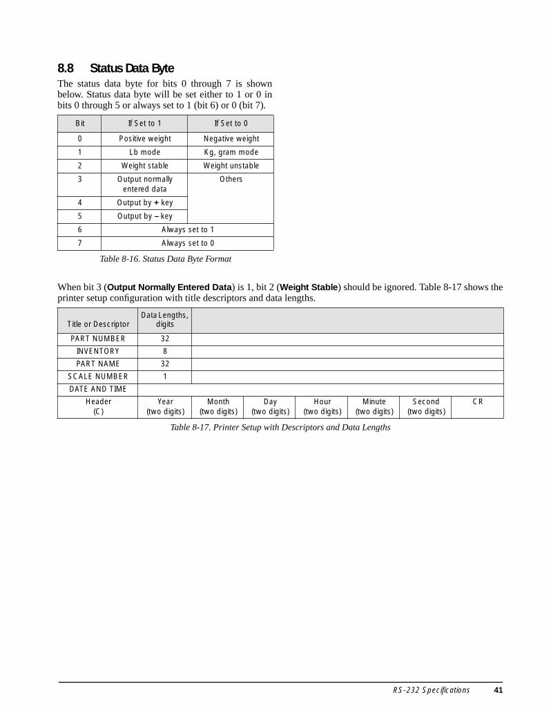
8.8 Status Data ByteThe status data byte for bits 0 through 7 is shownbelow. Status data byte will be set either to 1 or 0 inbits 0 through 5 or always set to 1 (bit 6) or 0 (bit 7).
When bit 3 (Output Normally Entered Data) is 1, bit 2 (Weight Stable) should be ignored. Table 8-17 shows theprinter setup configuration with title descriptors and data lengths.
Bit If Set to 1 If Set to 0
0 Positive weight Negative weight
1 Lb mode Kg, gram mode
2 Weight stable Weight unstable
3 Output normally entered data
Others
4 Output by + key
5 Output by – key
6 Always set to 1
7 Always set to 0
Table 8-16. Status Data Byte Format
Title or DescriptorData Lengths,
digits
PART NUMBER 32
INVENTORY 8
PART NAME 32
SCALE NUMBER 1
DATE AND TIME
Header(C)
Year(two digits)
Month(two digits)
Day(two digits)
Hour(two digits)
Minute(two digits)
Second(two digits)
CR
Table 8-17. Printer Setup with Descriptors and Data Lengths
RS-232 Specifications 41

8.9 Bar Code ScannersBar code scanning capabilities are available usingeither a laser scanner or a wand (or pen) scanner. Thelaser scanner allows non-contact, instantaneous, andaccurate input of unit weight, tare weight, and IDcode.
The scanner can become operational by connectingthe scanner cable to the DIN-8 connector in the rear ofthe console. The pen reader is an economical methodto use the accuracy and speed of bar code data inputwhen contact scanning is available. Be sure to verifythe correct settings on SPECs 14 and 15 (seeSection 4.2 on page 18).
Input Data FormatThe DC-190 provides two methods to input data; oneis with a header and the other, without a header. Theformat using a header is shown in the diagram below.
The format for without a header is shown below (dataidentified as an ID code).
Three Lines Bar CodeThe DC-190 can read three lines of bar code. Thefollowing illustrations show the configuration forLines 1, 2, and 3.
Line 1:
Line 2:
Line 3:
Communication available in the operation modeinclude, unit weight, tare weight, part code, andquantity.
Communication available in program mode include,part code, part number, part name, inventory, unitweight, tare weight and setpoints.
8.10 HeaderTable 8-18 presents the type of receivable header codeincluding ASCII code number and data description.
Header Data CR
Data CR
Header SP Data 1 CR
SP Data 2 CR
Data 3 CR
Header Code ASCII Code Data
1 31 Unit Weight
2 32 Quantity
3 33 ID Code
4 34 Tare Weight
A 41 Gross Weight
F 46 Setpoint 1 (W)
G 47 Setpoint 1 (Q)
H 48 Setpoint 2
I 49 Total Quantity
K 4B Inventory
M 4D Part Number
N 4E Part Name
Q 51 Setpoint 3
X 58 Setpoint 4
U 55 Setpoint 5
6 36 Setpoint 6
Table 8-18. Receivable Header Codes
42 DC-190 Ultra Count Installation Manual
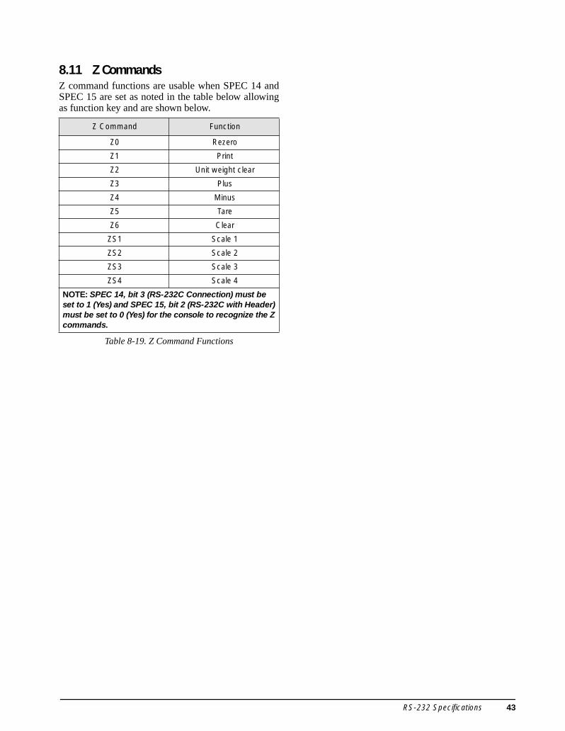
8.11 Z CommandsZ command functions are usable when SPEC 14 andSPEC 15 are set as noted in the table below allowingas function key and are shown below.
Z Command Function
Z0 Rezero
Z1 Print
Z2 Unit weight clear
Z3 Plus
Z4 Minus
Z5 Tare
Z6 Clear
ZS1 Scale 1
ZS2 Scale 2
ZS3 Scale 3
ZS4 Scale 4
NOTE: SPEC 14, bit 3 (RS-232C Connection) must be set to 1 (Yes) and SPEC 15, bit 2 (RS-232C with Header) must be set to 0 (Yes) for the console to recognize the Z commands.
Table 8-19. Z Command Functions
RS-232 Specifications 43

4
9.0 PC Connections and Label FormattingTo connect the DC-190 Ultra Count to a PC for usewith the IMS inventory management software, withHyperTerminal or other terminal emulation programs,or for creating and downloading labels, a null modemcable is required. The null modem cable must providethe following connections:
The DC-190 must also be configured for connectionto the PC (see Section 4.0 on page 17).
9.1 Using HyperTerminalOnce the DC-190 is configured for PC connection andconnected to the PC, start the HyperTerminalprogram.
9.1.1 HyperTerminal SetupSelect the name a port to be used for the connection,then set the port properties (see Figure 9-1). NOTE:Values specified for the PC port must match theDC-190 configuration for the port used.
Figure 9-1. HyperTerminal Port Properties Display
Click the Advanced… button and choose the type ofterminal emulation to use, then click the ASCIISetup… button. Click the checkbox to Append linefeeds to incoming line ends as shown in Figure 9-2.Click OK to finish HyperTerminal setup.
Figure 9-2. HyperTerminal ASCII Setup Display
9.1.2 Using HyperTerminal to Request DataOnce HyperTerminal is configured, scale data can besent to HyperTerminal by pressing the * key on theDC-190 console. The Z commands (see Section 8.11on page 43) can also be used.
To request data using the Z commands, type thecommand into a text editor window (such asNotepad), then press Enter to insert a carriage returnafter the command. Save the text file into yourHyperTerminal folder with a descriptive name such asZ1.txt.
In HyperTerminal, select Transfer, specify the name ofthe file that contains the Z command, then select SendText File. HyperTerminal opens the text file and sendsthe Z command to the DC-190. The DC-190 respondsby returning data to HyperTerminal.
9.1.3 Saving Data Sent to HyperTerminalTo save data sent to HyperTerminal, select Transfer, thenselect Capture Text. Highlight Capture Text and type thename of the file to store the data, then click Start. Pressthe * key on the DC-190 console or use a Z command(see above) to send scale data to HyperTerminal. Whendone, click Transfer and highlight Capture Text thenclick Stop.
9-pin Female 9-pin Male
1 1
2 3
3 2
4 6
5 5
6 4
7 8
8 7
Table 9-1. Null Modem Cable Connections
4 DC-190 Ultra Count Installation Manual

9.1.4 Example of HyperTerminal DataFigure 9-3 shows an example of a HyperTerminaldisplay of data returned from a 25-lb. DC-190 UltraCount counting scale configured as shown inTable 9-2. Table 9-3 describes the headers and datadisplayed in Figure 9-3.
Figure 9-3. HyperTerminal Data Display
See Section 8.6 on page 39 for more informationabout headers.
SPEC Value SPEC Value
00 0000 10 1111
01 0000 11 0000
02 1000 12 1000
03 0000 13 0011
04 1001 14 1010
05 1011 15 0011
06 1001 16 0001
07 0000 17 1011
08 0111 18 0000
09 0100 19 0000
Table 9-2. Sample DC-190 Configuration
Header Description Example Data
3 ID code —
M Alt part number —
N Part name —
E Lot number —
K Pieces in inventory —
G Setpoint 1 (quantity) 10000
H Setpoint 2 50
A Gross weight 0.840
0 Net weight 0.840
4 Tare weight 0.000
1 Weight per 1000 pieces 84.068
2 Quantity 10
C Date and time 030124072515
V Scale number 1
O Operator name —
B Status G*
Table 9-3. HyperTerminal Headers and Data
PC Connections and Label Formatting 45

9.2 Creating Labels for Eltron 2700-Series PrintersZebra Technologies’ Create-A-Label (CAL) software,supplied with the Eltron 2700-series printers, can beused to create both bar code and human-readablelabels for these printers. CAL supports importedgraphics in many formats, including PCX, JPG, TIF,BMP, and GIF.
With Create-A-Label software installed, start theCreate-A-Label program. Create a template file ordownload a template file from www.digiscales.com(see Figure 9-4). Resize as needed, then select SaveAs from the File menu to save and rename the file.From the Edit menu, select Label Setup.
Figure 9-4. Label Template, Showing Hidden Fields
Do not alter the hidden fields on the label template!
The hidden fields, designated V00–V18 and shown asred rrrrrrrrrrr’s in the label template, are used to link tothe DC-190 headers (see Table 9-4).
From the Draw menu, choose the label type.
• Graphics in any supported format can be sized tofit the label.
• Text can be specified as either fixed or linked.Linked text prints the contents of the headerfield it is linked to.
• Bar code labels are always linked.
9.2.1 Editing Text and Bar Code FieldsTo select a linked field, use the Linked Fieldspull-down as shown in Figure 9-5.
NOTE: The two tare weight fields (V04 and V14) andthe two weight per 1000 pieces fields (V09 and V13)support both bar code and human readable labels.Either field can be used.
Figure 9-5. Selecting a Linked Field
V# Variable Name (Character Length) Header
V00 ID Code (32) 3
V01 Quantity (8) 2
V02 Gross weight (6) A
V03 Net weight (6) 0
V04 Tare weight (6) 4
V05 Sequence number (8) none
V06 Date and time (32) none
V07 Alt. part number (32) M
V08 Part name (32) N
V09 Weight per 1000 pieces (6) 1
V10 Number of transactions (4) none
V11 Quantity in accumulation (6) I
V12 Lb, Kg, or grams (4) none
V13 Weight per 1000 pieces (6) 1
V14 Tare weight (6) 4
V15 Pieces in inventory (8) K
V16 Lot number (32) E
V17 Company name (48) D
V18 Operator name (32) O
Table 9-4. Create-A-Label Variable Fields
46 DC-190 Ultra Count Installation Manual

To insert a header code for a linked field, enter theheader code value enclosed in quotation marks (forexample, “1”) in front of the linked field identifier, asshown in Figure 9-6
Figure 9-6. Inserting a Header Code for a Linked Field
New text or bar code fields can be placed over thehidden fields of the label template (see Figure 9-7),but take care not to accidentally select a hidden field.Deleting or changing some hidden fields can cause thelabel to print incorrectly or not at all.
Figure 9-7. Bar Code Label Positioned on Label Template
If the length of some of the 32- or 48-character fieldsis not needed or is too long for your bar code labelstock, you can reduce the length of the bar code byshortening these fields.
To edit a hidden field, left-click once on the field, thenright-click and select Edit. (See Figure 9-8.)DO NOT CHANGE THE DEFAULT LENGTH OF THE GROSS,NET, OR TARE WEIGHT FIELDS!
Figure 9-8. Selecting a Hidden Field (V16)
9.2.2 Adding and Downloading Label GraphicsGraphics and logos can be added to a label anddownloaded to the printer using the Create-A-Labelprogram.
To add a graphic to a label, open label in theCreate-A-Label program. From the label screen, clickthe graphics button to show the Pictures dialog box;select the graphic to add from the pull-down menuthen click OK. Drag and drop the graphic into the labeland resize as needed.
Once label design is complete, use the Create-A-Labelprogram to download the label graphic to the printer.With the printer attached and the label format open inCreate-A-Label, select Download Label to Printer fromthe File menu. In the dialog box, use the Add button tomove the selected graphic to the Selected Labels sideof the dialog box, then click Download (seeFigure 9-9).
Figure 9-9. Selecting Label Graphic for Download
The label format itself must be edited thendownloaded using the ELTRTERM.EXE program.See the following sections for more information.
PC Connections and Label Formatting 47

9.2.3 Generating the EPL and EJF FilesWhen the label design is complete, save the label, thenselect Generate EPL Source File (see Figure 9-10 onpage 48). When the Print to File pop-up menu appearswith the selected file with a .BIN extension, click OKto save the file.
Figure 9-10. Generate EPL Source File
Another pop-up menu appears, this time showing an.EJF extension. Click OK to save the file.
9.2.4 Editing the EJF FileBefore downloading the EJF file, several fields mustbe edited. Open the file in WordPad or NotePad, thendo the following:
• Change the “O” in the first line to an “N”.• In all listed variables (V00–V18), change the
“L” (left justification) to an “N” (nojustification.
See Figure 9-11 for the location of these fields.
Figure 9-11. Editing the EJF File
After editing the file (see Figure 9-12), select Save orSave As to save the EJF file.
Figure 9-12. Edited EJF File
48 DC-190 Ultra Count Installation Manual
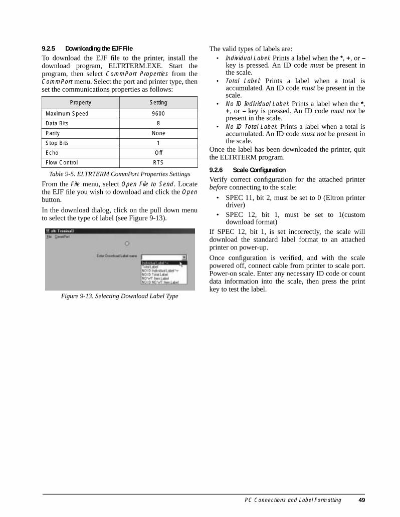
9.2.5 Downloading the EJF FileTo download the EJF file to the printer, install thedownload program, ELTRTERM.EXE. Start theprogram, then select CommPort Properties from theCommPort menu. Select the port and printer type, thenset the communications properties as follows:
From the File menu, select Open File to Send. Locatethe EJF file you wish to download and click the Openbutton.
In the download dialog, click on the pull down menuto select the type of label (see Figure 9-13).
Figure 9-13. Selecting Download Label Type
The valid types of labels are:• Individual Label: Prints a label when the *, +, or –
key is pressed. An ID code must be present inthe scale.
• Total Label: Prints a label when a total isaccumulated. An ID code must be present in thescale.
• No ID Individual Label: Prints a label when the *,+, or – key is pressed. An ID code must not bepresent in the scale.
• No ID Total Label: Prints a label when a total isaccumulated. An ID code must not be present inthe scale.
Once the label has been downloaded the printer, quitthe ELTRTERM program.
9.2.6 Scale ConfigurationVerify correct configuration for the attached printerbefore connecting to the scale:
• SPEC 11, bit 2, must be set to 0 (Eltron printerdriver)
• SPEC 12, bit 1, must be set to 1(customdownload format)
If SPEC 12, bit 1, is set incorrectly, the scale willdownload the standard label format to an attachedprinter on power-up.
Once configuration is verified, and with the scalepowered off, connect cable from printer to scale port.Power-on scale. Enter any necessary ID code or countdata information into the scale, then press the printkey to test the label.
Property Setting
Maximum Speed 9600
Data Bits 8
Parity None
Stop Bits 1
Echo Off
Flow Control RTS
Table 9-5. ELTRTERM CommPort Properties Settings
PC Connections and Label Formatting 49
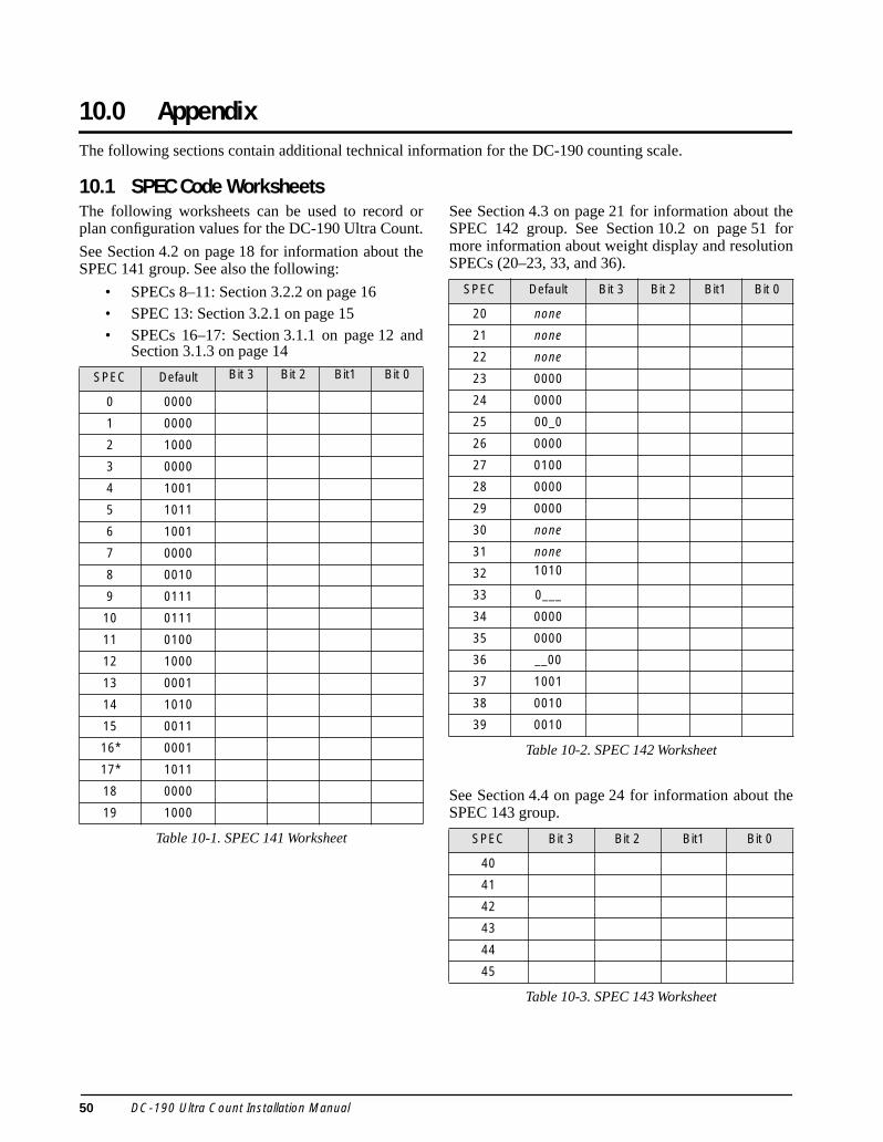
10.0 AppendixThe following sections contain additional technical information for the DC-190 counting scale.
10.1 SPEC Code WorksheetsThe following worksheets can be used to record orplan configuration values for the DC-190 Ultra Count.
See Section 4.2 on page 18 for information about theSPEC 141 group. See also the following:
• SPECs 8–11: Section 3.2.2 on page 16• SPEC 13: Section 3.2.1 on page 15• SPECs 16–17: Section 3.1.1 on page 12 and
Section 3.1.3 on page 14
See Section 4.3 on page 21 for information about theSPEC 142 group. See Section 10.2 on page 51 formore information about weight display and resolutionSPECs (20–23, 33, and 36).
See Section 4.4 on page 24 for information about theSPEC 143 group.
SPEC Default Bit 3 Bit 2 Bit1 Bit 0
0 0000
1 0000
2 1000
3 0000
4 1001
5 1011
6 1001
7 0000
8 0010
9 0111
10 0111
11 0100
12 1000
13 0001
14 1010
15 0011
16* 0001
17* 1011
18 0000
19 1000
Table 10-1. SPEC 141 Worksheet
SPEC Default Bit 3 Bit 2 Bit1 Bit 0
20 none
21 none
22 none
23 0000
24 0000
25 00_0
26 0000
27 0100
28 0000
29 0000
30 none
31 none
32 1010
33 0___
34 0000
35 0000
36 __00
37 1001
38 0010
39 0010
Table 10-2. SPEC 142 Worksheet
SPEC Bit 3 Bit 2 Bit1 Bit 0
40
41
42
43
44
45
Table 10-3. SPEC 143 Worksheet
50 DC-190 Ultra Count Installation Manual

10.2 Scale Capacity and Display ResolutionThe weight display resolution of a scale can bedetermined by dividing the scale capacity by thedisplay, or “count-by”, increments:
Resolution = Scale_Capacity / Display_Increments
For example, to configure a 50-lb scale to displayweights in 0.01-lb increments, the required resolutionwould be 5000:
Resolution = 50 / 0.01 = 5000
Table 10-4 shows display increment values for typicalDC-190 scale bases. The display increment valuesshown are calculated by dividing the scale capacity bydisplay resolution values that can be configured withSPEC 23 (1/2500, 1/5000, 1/10000).
Once the display resolution is selected, the minimumdisplay increment value (1, 2, or 5) and the decimalposition can be chosen. Table 10-5 lists the SPECsused to configure display resolution, minimum displayincrement, and decimal position for scales 1–3.
NominalCapacity
Display Resolution(SPEC 23) Display Increments
0.5 2500 0.0002
5000 0.0001
1.0 5000 0.0002
10000 0.0001
2.5 2500 0.001
5000 0.0005
5.0 2500 0.002
5000 0.001
10000 0.0005
10 5000 0.002
10000 0.001
25 2500 0.01
5000 0.005
50 2500 0.02
5000 0.01
10000 0.005
100 5000 0.02
10000 0.01
250 2500 0.1
5000 0.05
500 2500 0.2
5000 0.1
10000 0.05
1000 5000 0.2
10000 0.1
Table 10-4. Displayed Increments Based on Scale Capacity and Display Resolution
Specification Scale Number SPEC Number
Display Resolution All SPEC 23, bits 3–2
Minimum Display 1 SPEC 20, bits 3–2
2 SPEC 20, bits 1–0
3 SPEC 36, bits 3–2
Decimal Position 1 SPEC 21, bits 2–0
2 SPEC 22, bits 2–0
3 SPEC 33, bits 2–0
NOTE: Scale number refers to the physical scale number,not the displayed scale number shown when switchingbetween scales.
Table 10-5. Weight Display Configuration SPECs
Appendix 51

10.3 Connector PinoutsThe DC-190 provides CTS/RTS hardware handshaking lines on both the 8-pin DIN and 9-pin D-Sub connectors.For devices that do not require hardware handshaking, short the CTS/RTS lines on the scale side of the cable.
8-Pin DIN Female
Figure 10-1. 8-Pin DIN Female
14-Pin Amphenol
Figure 10-2. 14-Pin Amphenol Female
9-Pin D-Sub Female
Figure 10-3. 9-Pin D-Sub Female
Setpoint Mini DIN
Figure 10-4. Setpoint Mini DIN Female
Pin Number
Scanner DIN Connector
Force Balance DIN Connector
1 DTR DTR
2 SIGNAL GND SIGNAL GND
3 DSR DSR
4 RXD RXD
5 TXD TXD
6 CTS CTS
7 RTS RTS
8 Vcc (5 V) N/C
Table 10-6. Eight-Pin DIN Connector Pin Assignments
Pin NumberRemote Platform Connector
Description
1 Not used
2
3 +EXCITATION
4 –EXCITATION
5 SHIELD*
6 +SIGNAL
7 –SIGNAL
8 GROUND*
9 through 14 Not used
* When using the Y cable, use pin 5 instead of pin 8 as ground.
Table 10-7. Remote Platform Pin Assignments
Pin Number Description
1 DCD
2 RXD
3 TXD
4 DTR
5 SIGNAL GND
6 DSR
7 RTS
8 CTS
9 RI
Table 10-8. 9-Pin D-Sub Connector Pin Assignments
Pin Number Setpoint Configuration
1 SP-1
2 SP-2
3 SP-3
4 SP-4
5 SP-5
6 SP-6
7 +5V
8 GND
Table 10-9. Setpoint Configuration Pin Assignments
52 DC-190 Ultra Count Installation Manual

Figure 10-5 shows how the DC-190 can be attached to output relays for setpoint control of external equipment.Components shown include a four-channel relay rack (PN 19365) with four output relays (PN 15971).
Figure 10-5. Typical Wiring for 4 AC Output Relays to Control Equipment
SP
AR
EF
US
E
FU
SE
TE
ST
ER
12
34
56
78
9
23
45
67
89
OPTO 22G4PB4
FIELD CONTROL
OAC5 OUT
OAC5 OUT
OAC5 OUT
OAC5 OUT
FUSE-HIGH VOLTAGEAC IN OU
T –
+
COMHOTGRD
AC
WIR
ING
TO
CO
NTR
OLL
ED
EQ
UIP
ME
NT
IN F
IELD
DC
CO
NTR
OL
WIR
ING
FR
OM
DC
-190
AC OUTPUT 4 TOEQUIPMENT
AC OUTPUT 1 TOEQUIPMENT
AC OUTPUT 2 TOEQUIPMENT
AC OUTPUT 3 TOEQUIPMENT
115 VACHOT IN
PIN 1 - SETPOINT 1PIN 2 - SETPOINT 2
PIN 3 - SETPOINT 3
PIN 4 - SETPOINT 4
PIN 7 - 5 VDCPIN 8 - GND
CAUTION:DO NOT REVERSEHOT AND COMMON
POWER SUPPLYPROVIDED BY CUSTOMER
OR SPECIAL ORDER
Appendix 53

10.4 Cable WiringThe following tables show wiring specifications for cables used with the Epson TM-U295/TM-U200, Eltron2722/2742, and Digi BCP-300 printers.
10.4.1 TM-U295/TM-U200 CablesCable PN 41279
Cable PN 32810
10.4.2 Eltron 2722/2742 CablesCable PN 64660
Cable PN 64661
10.4.3 BCP-300 CableCable PN 73106
TM-U295/TM-U20025-pin D-Sub Male
DC-1909-pin D-Sub Male
Function Pin Pin Function
TxD 2 2 RxD
RxD 3 3 TxD
GND 7 5 GND
NOTE: When making your own cable, short the following pins: 25-pin D-Sub: Pin 6 (DSR) to 20 (DTR), 4 (RTS) to 5 (CTS)9-pin D-Sub: Pin 4 (DTR) to 6 (DSR), 7 (RTS) to 8 (CTS)
Table 10-10. Wiring for Cable PN 41279, TM-U295/TM-U200
TM-U295/TM-U20025-pin D-Sub Male
DC-1908-pin DIN Male
Function Pin Pin Function
TxD 2 4 RxD
RxD 3 5 TxD
GND 7 2 GND
NOTE: When making your own cable, short the following pins: 25-pin D-Sub: Pin 6 (DSR) to 20 (DTR), 4 (RTS) to 5 (CTS)8-pin DIN: Pin 1 (DTR) to 3 (DSR), 6 (CTS) to 7 (RTS)
Table 10-11. Wiring for Cable PN 32810, TM-U295/TM-U200
Eltron 2722/27429-pin D-Sub Male
DC-1909-pin D-Sub Male
Function Pin Pin Function
RxD 3 3 TxD
GND 5 5 GND
RTS 7 7 RTS
CTS 8 8 CTS
Table 10-12. Wiring for Cable PN 64660, Eltron 2722/2742
Eltron 2722/27429-pin D-Sub Male
DC-1908-pin DIN Male
Function Pin Pin Function
RxD 3 5 TxD
GND 5 2 GND
RTS 7 7 RTS
CTS 8 6 CTS
Table 10-13. Wiring for Cable PN 64661, Eltron 2722/2742
BCP-300RJ-11
Wire Color
DC-1908-pin DIN Male
Pin Pin
1 White 1
2 Black 2
3 Red 3
4 Green 4
5 Yellow 5
6 Blue 6
— — 7
— — 8
Table 10-14. Wiring for Cable PN 73106, Digi BCP-300
54 DC-190 Ultra Count Installation Manual

10.5 Y-Cable Wiring DiagramFigure 10-6 shows a wiring diagram for the Y-cable used to attach a separate remote platform as interna.l scale 2(Port 1 connector).
Figure 10-6. Y-Cable Wiring Diagram
1
2
3
4
5
6
7
8
9
10
11
12
13
14
6
7
3
4
5
6
7
3
4
5
9
10
11
12
13
14
+ SIGNAL
– SIGNAL
+ EXCITATION
– EXCITATION
SHIELD
+ SIGNAL
– SIGNAL
+ EXCITATION
– EXCITATION
SHIELD
Vpac
GND
V+
VDC
Vbat
CHG BAT
14-pin FEMALECONNECTOR
14-pin MALECONNECTOR
SXONLY
SCALE 1
SCALE 2
Appendix 55
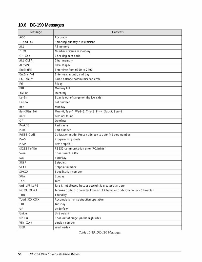
10.6 DC-190 MessagesMessage Contents
ACC Accuracy
---Add XX Sampling quantity is insufficient
ALL All memory
C XX Number of items in memory
CH XXX Checking item code
ALL CLEAr Clear memory
dFt SPC Default spec
EntEr tIñE Enter time from 0000 to 2400
EntEr y-ñ-d Enter year, month, and day
Fb CoñErr Force balance communication error
Frl Friday
FULL Memory full
InVEnt Inventory
Lo-Err Span is out of range (on the low side)
Lot-no Lot number
ñon Monday
ñon-SUn 0-6 Mon=0, Tue=1, Wed=2, Thu=3, Fri=4, Sat=5, Sun=6
not F Item not found
OF Overflow
P-nAñE Part name
P-no Part number
PrESS CodE Calibration mode: Press code key to auto find zero number
ProG Programming mode
P-SP Item setpoint
rS232 CoñErr RS232 communication error (PC/printer)
S-on Span switch is ON
Sat Saturday
SEt P Setpoint
SEt X Setpoint number
SPCXX Specification number
SUn Sunday
TArE Tare
tArE oFF LoAd Tare is not allowed because weight is greater than zero
t-C XX XX-XX Teraoka Code I Character Position I Character Code Character - Character
THU Thursday
TotAL XXXXXXX Accumulation or subtraction operation
TUE Tuesday
UF Underflow
Unit u Unit weight
UP-Err Span out of range (on the high side)
VEr X.XX Version number
UED Wednesday
Table 10-15. DC-190 Messages
56 DC-190 Ultra Count Installation Manual

10.7 Clearing Locked-Up Scale (888888 Error)Several configuration errors can result in the scale locking up with a display that shows all 888888s. These errorsinclude the following:
• If no force balance is connected to the DC-190, SPEC 8, bit 3, must be set to 0 (0xxx).• If a force balance is attached, SPEC 8, bit 3 must be set to 1 (1xxx) and SPEC 9, bit 2 (force balance
type), must be set to 1 (x1xx, Ohaus Explorer).• If no printer is attached to the DC-190, SPEC 10, bit 3, must be set to 0 (0xxx).• SPEC 16 and SPEC 17 must assign a different location for each scale, whether it is present or not. These
bits must be configured to show scale assignments for Internal Scale 1, Internal Scale 2, External Scale,and Force Balance. See example below.
The following configuration for SPECs 16 and 17 contains duplicate entries for both Internal Scale 1and External Scale. Do NOT set SPECs 16 and 17 to a configuration such as that shown below: alockup condition will result if this configuration is selected.
Should the DC-190 become locked up in all 888888s as a result of invalid specification settings, an authorizedservice technician can perform the following procedure:
1. Unplug scale from AC outlet.2. Press and hold the 3 and 9 keys while plugging AC cord into outlet.
3. The display shows S-on. Release the 3 and 9 keys.
4. Press and hold REZERO key while keying access code 141 (display will show SPC00). Use the + key toadvance to the incorrect SPEC and edit its value.
5. When done, press the * key to store the new values, then press the MODE key to return to weighingmode.
SPEC Setting Bits 2 and 3 Bits 0 and 1
16 0010 Scale 100: Internal Scale 1
Scale 210: External scale
17 1000 Scale 310: External scale
Scale 400: Internal Scale 1
Caution
Appendix 57

10.8 DC-190 Character Code List (Teraoka Code)The DC-190 is not equipped with a full alphanumeric keyboard, but the Teraoka Code listed in Table 10-16 canbe used to enter a code number representing the character you want entered. For example, if you want to enter theletter A, you would enter the Code 01.
The Teraoka Code can be used in the programming mode (see Section 7.0 on page 30) to enter an alphanumericitem code number, part number, part name, and lot number. You will know that you are in the Teraoka modebecause the WEIGHT display will always prompt t-C 01 and the UNIT-WEIGHT display will show 00-. TheQUANTITY display will prompt CodE, PArt-no, P-nAme, or Lot-no depending on the data you are entering. Thedisplay will show t-C and 00- and will prompt you to enter the first character. Once you enter the character, usingthe code equivalent, the displays will read t-C 02 and 00-. Pressing the + key allows you to move to the nextcharacter or leave a space between characters, and pressing the – key allows you to review characters alreadyentered.
Character Code Character Code Character Code Character Code
Space 00 M 13 Z 26 9 39
A 01 N 14 , 27 @ 40
B 02 O 15 . 28 ! 41
C 03 P 16 – 29 " 42
D 04 Q 17 0 30 # 43
E 05 R 18 1 31 $ 44
F 06 S 19 2 32 % 45
G 07 T 20 3 33 & 46
H 08 U 21 4 34 / 47
I 09 V 22 5 35 ( 48
J 10 W 23 6 36 ) 49
K 11 X 24 7 37 ‘ 50
L 12 Y 25 8 38
Table 10-16. DC-190 Character Code List (Teraoka Code)
58 DC-190 Ultra Count Installation Manual

10.9 Bar Code Board
Appendix 59

10.10 PSC QuickScan 6000 SetupFigures 10-7 and 10-8 (see page 61) provide setup scans for the PSC® QuickScan® 6000. See also SPECs 14 and15 in Table 4-1 on page 50.
Figure 10-7. Scan Sheet for PSC QuickScan 6000 (Part 1)
EVEN PARITY
1 STOP BIT
7 DATA BITS
SET
SCAN SET
SCAN END
SCAN SET
SCAN END
SCAN SET
SCAN END
4800 BAUD
DELAY NONE
SCAN SET
SCAN END
DISABLE ACK/NACK
SCAN SET
SCAN END
DISABLE HARDWARE
DISABLE XON/XOFF
DISABLE CTS/RTS
END
60 DC-190 Ultra Count Installation Manual

Figure 10-8. Scan Sheet for PSC QuickScan 6000 (Part 2)
SCAN SET
SCAN SET
SCAN END
SCAN END
SET SUFFIX
SUFFIX D
SUFFIX 0
DISABLE I.D. CONTROL
SCAN SET
SCAN END
DON’T COMPUTE
DON’T TRANSMIT
ENABLE FULL ASCII 39
SET
END
SCAN SET
SCAN END
SET “0”
SET “0”
SET MINIMUM LENGTH
Appendix 61

10.11 DC-190 Ultra Count SpecificationsPowerPower source 100–120VAC or 220–240 VAC at
50/60 HzPower consumption 20 W
Analog SpecificationsInput sensitivity 0.40–4.00 mV/VZero adjustment range 100% FSA/D conversion rate 10/secLoad cell excitiation 12V DCLoad cells per scale 4 x 350ΩLoad cell connectors 2 x 14-pin AmphenolScale channels Up to four: three analog (load cell)
scales, plus one force balanceWeightdisplay resolution 1/10000, 1/5000, 1/2500Counting resolution 1/1000000
Digital SpecificationsWeight display 5 digitsUnit weight display 5 digitsQuantity display 7 digitsItem memory 200 items, expandable with IMS
software
Serial Communications and Setpoint ConnectorsSCANNER port 8-pin DIN, RS-232CFORCE BALANCE port 8-pin DIN, RS-232C232C/PRINTER port 9-pin D-Sub, RS-232CSetpoint output 8-pin mini-DIN, 24V open collector
EnvironmentalOperating temperature 14°F to 104°F (–10°C ° to 40°C)Operating humidity 10% – 80% relative humidity
PhysicalBench type 16.4 in (W) x 17.1 in (D) x 4.9 in (H)
41.7 cm (W) x 43.4 cm (D) x 12.4 cm (H)17.6 lb (8.0 Kg)
Pole type 16.4 in (W) x 16.5 in (D) x 17.9 in (H)41.7 cm (W) x 41.9 cm (D) x 45.5 cm (H)19.4 lb (8.8 Kg)
62 DC-190 Ultra Count Installation Manual
DC-190 Ultra Count Limited WarrantyRice Lake Weighing Systems (RLWS) warrants that all RLWS equipment and systems properly installed by aDistributor or Original Equipment Manufacturer (OEM) will operate per written specifications as confirmed bythe Distributor/OEM and accepted by RLWS. All systems and components are warranted against defects inmaterials and workmanship for two (2) years.
RLWS warrants that the equipment sold hereunder will conform to the current written specifications authorizedby RLWS. RLWS warrants the equipment against faulty workmanship and defective materials. If any equipmentfails to conform to these warranties, RLWS will, at its option, repair or replace such goods returned within thewarranty period subject to the following conditions:
• Upon discovery by Buyer of such nonconformity, RLWS will be given prompt written notice with adetailed explanation of the alleged deficiencies.
• Individual electronic components returned to RLWS for warranty purposes must be packaged toprevent electrostatic discharge (ESD) damage in shipment. Packaging requirements are listed in apublication, Protecting Your Components From Static Damage in Shipment, available from RLWSEquipment Return Department.
• Examination of such equipment by RLWS confirms that the nonconformity actually exists, and wasnot caused by accident, misuse, neglect, alteration, improper installation, improper repair orimproper testing; RLWS shall be the sole judge of all alleged non-conformities.
• Such equipment has not been modified, altered, or changed by any person other than RLWS or itsduly authorized repair agents.
• RLWS will have a reasonable time to repair or replace the defective equipment. Buyer is responsiblefor shipping charges both ways.
• In no event will RLWS be responsible for travel time or on-location repairs, including assembly ordisassembly of equipment, nor will RLWS be liable for the cost of any repairs made by others.
THESE WARRANTIES EXCLUDE ALL OTHER WARRANTIES, EXPRESSED OR IMPLIED, INCLUDING WITHOUTLIMITATION WARRANTIES OF MERCHANTABILITY OR FITNESS FOR A PARTICULAR PURPOSE. NEITHERRLWS NOR DISTRIBUTOR WILL, IN ANY EVENT, BE LIABLE FOR INCIDENTAL OR CONSEQUENTIAL DAMAGES. RLWS AND BUYER AGREE THAT RLWS’S SOLE AND EXCLUSIVE LIABILITY HEREUNDER IS LIMITED TOREPAIR OR REPLACEMENT OF SUCH GOODS. IN ACCEPTING THIS WARRANTY, THE BUYER WAIVES ANY ANDALL OTHER CLAIMS TO WARRANTY.SHOULD THE SELLER BE OTHER THAN RLWS, THE BUYER AGREES TO LOOK ONLY TO THE SELLER FORWARRANTY CLAIMS.NO TERMS, CONDITIONS, UNDERSTANDING, OR AGREEMENTS PURPORTING TO MODIFY THE TERMS OF THISWARRANTY SHALL HAVE ANY LEGAL EFFECT UNLESS MADE IN WRITING AND SIGNED BY A CORPORATEOFFICER OF RLWS AND THE BUYER.
© 2003 Rice Lake Weighing Systems, Inc. Rice Lake, WI USA. All Rights Reserved.
RICE LAKE WEIGHING SYSTEMS • 230 WEST COLEMAN STREET • RICE LAKE, WISCONSIN 54868 • USA
Appendix 63