
M-23E Switch and Lock Movement - Hitachi Rail
66
Union Switch & Signal Inc., an Ansaldo Signal company 1000 Technology Drive, Pittsburgh, PA 15219 Batesburg, SC 29006 SM 7100 Copyright © 2001 NOVEMBER 2001 Union Switch & Signal Inc. Rev. 0 M-23E Switch and Lock Movement with Electronic Circuit Controller (ECC) Installation < Operation < Maintenance < Adjustment <
Transcript of M-23E Switch and Lock Movement - Hitachi Rail

Union Switch & Signal Inc., an Ansaldo Signal company
1000 Technology Drive, Pittsburgh, PA 15219 ������5XVVHOO�6WUHHW��Batesburg, SC 29006 SM 7100
Copyright © 2001 NOVEMBER 2001Union Switch & Signal Inc. Rev. 0
M-23E Switch and LockMovement
with Electronic Circuit Controller (ECC)
Installation �Operation �
Maintenance �
Adjustment �


SM 7100, Rev. 0 (11/01) i
This document and its contents are the property of Union Switch & SignalInc. (US&S). This document has been furnished to you under the followingconditions: no right or license under any patents or any other proprietaryright in respect of this document or its content is given or waived insupplying this document; this document or its content are not to be used ortreated in any manner inconsistent with the rights of US&S, or to itsdetriment; and this document shall not be copied, reproduced, disclosed toothers, or disposed of except with the prior written consent of US&S.
Important Notice
Based on our experience, you will obtain the best possible operational reliability by following therecommendations given in these instructions. The data contained herein describes US&S’s product,and it is not a warranty of performance or characteristics. It is with the best interests of our customersin mind that US&S constantly strives to improve our products and keep them current with advances intechnology.
Within the scope of these instructions, US&S recognizes that it is impossible to take into accountevery eventuality that may arise with technical equipment in service. Please consult our local salesrepresentative in the event of any irregularities, especially if such irregularity is not referenced herein.
US&S expressly declines liability for damages resulting from any incorrect operation or improperhandling of our equipment, even if these instructions contain no specific indication in this respect. Westress that only genuine US&S spare parts should be used for replacements.
Copyright © 2001, Union Switch & Signal Inc. All rights reserved.

ii SM 7100, Rev. 0 (11/01)
!UNION SWITCH & SIGNAL!~

SM 7100, Rev. 0 (11/01) iii
REVISION INDEX
Revised pages of this manual are listed by page number and date of revision.
Page No. Rev. Date
Original Publication November, 2001
FCC PART 15 COMPLIANCEThis equipment has been tested and found to comply with the limitsfor a Class A digital device, pursuant to Part 15 Rules. These limitsare designed to provide reasonable protection against harmfulinterference when the equipment is operated in a commercialenvironment. This equipment generates, uses, and can radiate radiofrequency energy and, if not installed and used in accordance withthis instruction manual, may cause harmful interference to radiocommunications. Operation of this equipment in a residential areais likely to cause harmful interference in which case the user will berequired to correct the interference at his own expense.

iv SM 7100, Rev. 0 (11/01)
!UNION SWITCH & SIGNAL!~
TABLE OF CONTENTS
SM 7100 (11/01) v
Table of ContentsSection 1. Introduction............................................................................................ 1-1
1.1. The M-23E
Switch Machine with Electronic Circuit Controller (ECC)(PN: N422551 and N422552) .............................................................................................. 1-1RAIL TEAM AND TECHNICAL SUPPORT.......................................................................... 1-2
Section 2. Definitions.............................................................................................. 2-1Section 3. Description ............................................................................................ 3-1
3.1. The Motor Compartment (reference Figure 3-2 and Figure 3-3)...................... 3-13.1.1. The Transmission Box .................................................................................... 3-13.1.1.1 Hand-crank Plunger Mechanism..................................................................... 3-23.1.2. Voltage ........................................................................................................... 3-23.1.3. Cycle Counter................................................................................................. 3-23.1.4. WAGO® Terminal Strip ................................................................................... 3-23.1.5. Field Cable Conduit ........................................................................................ 3-33.1.6. AAR Binding Posts ......................................................................................... 3-3
3.2. The Gearbox Compartment (reference Figure 3-4 and Figure 3-5) ................. 3-33.2.1. Gearbox Components and Assemblies........................................................... 3-33.2.2. Motor Cutout Proximity Sensor ....................................................................... 3-53.2.3. Gearbox Configurations.................................................................................. 3-5
3.3. The Circuit Controller Compartment (see Figure 3-6 and Figure 3-7) ............. 3-53.3.1. Frog Plate....................................................................................................... 3-53.3.2. Vital Locking Sensors ..................................................................................... 3-53.3.3. ECC Box......................................................................................................... 3-53.3.4. Junction Box................................................................................................... 3-73.3.5. Captive Point Detection System (CPDS) ........................................................ 3-73.3.6. Point Detector Target...................................................................................... 3-83.3.7. Linear Slides................................................................................................... 3-83.3.8. Vital Sensor Position Monitoring ..................................................................... 3-83.3.9. Non-Vital Auxiliary Sensors (when Included) .................................................. 3-83.3.10. Local/Remote Request Switches .................................................................... 3-8
Section 4. Operation............................................................................................... 4-14.1. General Overview........................................................................................... 4-1
4.1.1. “Power” Operation .......................................................................................... 4-14.1.2. “Manual” Operation via the Hand-Throw Lever ............................................... 4-14.1.3. “Manual” Operation via the Hand-Crank ......................................................... 4-14.1.4. Main-Crank Rotation....................................................................................... 4-14.1.5. ECC Monitoring .............................................................................................. 4-2
4.2. MANUAL OPERATION................................................................................... 4-24.2.1. Hand-Throw Lever Operation ......................................................................... 4-24.2.2. Hand-Crank Operation.................................................................................... 4-3
4.3. POWER OPERATION.................................................................................... 4-34.3.1. Power (Motor) Operation ................................................................................ 4-4
4.4. ECC OPERATION AND MONITORING.......................................................... 4-44.4.1. Proximity Sensors........................................................................................... 4-44.4.2. Vital Point and Lock Sensors .......................................................................... 4-44.4.3. Latch-Out........................................................................................................ 4-54.4.4. Auxiliary Sensors (when Included).................................................................. 4-54.4.5. Manual Operation Motor-Cutoff Protection...................................................... 4-6

TABLE OF CONTENTS
vi SM 7100, Rev. 0 (11/01)
4.5. ECC DIAGNOSTIC INFORMATION ............................................................... 4-64.5.1. LEDs............................................................................................................... 4-64.5.2. Vital Sensor Monitoring and Led Diagnostic Representation........................... 4-74.5.3. Diagnostic Modes of Dual-Colored LEDs........................................................ 4-7
Section 5. Wiring and Motor Control....................................................................... 5-15.1. WAGO® Terminal strip Connections (See Figure 5-3)..................................... 5-1
5.1.1. Terminals 1 and 3: Two-Wire, Bipolar Indication Output Circuit ...................... 5-15.1.2. Terminals 4, 6, 7, and 9: Four-Wire Indication Output Circuit .......................... 5-15.1.3. Terminals 10, 12, 13 and 15: Indication Input ................................................. 5-25.1.4. Wayside Battery Connections......................................................................... 5-25.1.5. Bipolar Auxiliary Sensor Output ...................................................................... 5-25.1.6. Local/Remote Request Switch Option............................................................. 5-35.1.7. Motor Control Unit and Cycle Counter Termination......................................... 5-35.1.8. Motor Cutout Circuits Termination Points........................................................ 5-45.1.9. MCU Test Procedure ...................................................................................... 5-4
5.2. AAR Terminal Post Connections..................................................................... 5-55.3. Sensor Identification and Termination in the Junction Box.............................. 5-55.4. 3- and 5-Wire Control Conversion to 2-Wire Control (See Figure 5-2) ............ 5-6
Section 6. Installation ............................................................................................. 6-16.1. Component Conversion - Right- to Left-Hand (and vice versa) ....................... 6-1
6.1.1. Gearbox Conversion....................................................................................... 6-16.1.2. Circuit Controller Conversion .......................................................................... 6-26.1.3. Operating Bar Conversion .............................................................................. 6-3
6.2. M-23E Mounting Details ................................................................................. 6-46.3. Field Installation of Machine ........................................................................... 6-4
6.3.1. Lifting and Handling the M-23E....................................................................... 6-46.3.2. Placing the M-23E on the Ties........................................................................ 6-6
6.4. Junction Box Jumper Configuration ................................................................ 6-76.4.1. RHPC/LHPC Jumpers .................................................................................... 6-76.4.2. Latch-Out Jumper Configuration ..................................................................... 6-76.4.3. Changing the Jumper Configurations.............................................................. 6-7
6.5. ECC Power and Indications Set-up................................................................. 6-76.5.1. Single Machine Indication ............................................................................... 6-86.5.2. Multiple Machine Applications......................................................................... 6-8
6.6. Point Detector Sensor Gap Adjustment (refer to Figure 6-2)........................... 6-86.7. Operating Rod Adjustment.............................................................................. 6-86.8. Point Detector Linear Slide Adjustment........................................................... 6-96.9. Lock Rod Adjustment.................................................................................... 6-106.10. Final Inspection and Testing after Installation ............................................... 6-10
Section 7. Periodic Maintenance............................................................................ 7-17.1. Required Tools ............................................................................................... 7-17.2. Lubrication...................................................................................................... 7-1
Section 8. Troubleshooting..................................................................................... 8-1Section 9. Parts List ............................................................................................... 9-1
9.1. M-23E Dual-Control Switch Machine (D422551 and D422552)....................... 9-19.2. N42203101 M23E-A-Gear B / N42203102 M23E-B-Gear B............................ 9-19.3. ...................................................................................................................................... 9-29.4. N42205101 / N42205101 Transmission Box Assembly................................... 9-2

TABLE OF CONTENTS
SM 7100 (11/01) vii
List of FiguresFigure Page
Figure 1-1. M-23E Switch Machine ............................................................................. 1-1
Figure 2-1.- Right Hand Machine, Right Hand Point Closed Application (RHPC) ........ 2-2
Figure 3-1. M-23E Switch Machine Compartments..................................................... 3-1
Figure 3-2. Detailed View of the Motor Compartment Unit .......................................... 3-4
Figure 3-3. Detailed View of Transmission Box........................................................... 3-4
Figure 3-4. Detailed View of Gearbox ......................................................................... 3-6
Figure 3-5. Top View of Gear Box............................................................................... 3-6
Figure 3-6. Controller Compartment............................................................................ 3-9
Figure 3-7. Controller Compartment with Sensor View ............................................... 3-9
Figure 3-8. M-23E ECC System Block Diagram........................................................ 3-10
Figure 4-1. Alternate Hand-Throw Pinion Gears ......................................................... 4-2
Figure 5-1. Top View-Controller Compartment............................................................ 5-6
Figure 5-2. Wiring Changes from 3-Wire and 5-Wire to 2-Wire Motor Control ............ 5-7
Figure 5-3. Internal Wiring Diagram ............................................................................ 5-8
Figure 6-1. M-23E Proper Lifting Illustration................................................................ 6-5
Figure 6-2. Sensor Gap Definition............................................................................... 6-9
List of TablesTable Page
Table 4-1. LED Diagnostics......................................................................................... 4-7
Table 8-1. Troubleshooting Guide............................................................................... 8-1

viii SM 7100, Rev. 0 (11/01)
!UNION SWITCH & SIGNAL!~

SECTION 1 - INTRODUCTION
SM 7100, Rev. 0 (11/01) 1-1
SECTION 1. INTRODUCTION1.1. The M-23E Switch Machine with Electronic Circuit Controller
(ECC) (PN: N422551 and N422552)
Figure 1-1. M-23E Switch Machine
The M-23E (Figure 1-1) is the next generation “M” style switch machine developed by UnionSwitch & Signal. The M-23E design provides a state-of-the-art Electronic Circuit Controller(ECC); simple mechanical, modular construction; and a lower level of required maintenance.In addition, all serviceable parts of the M-23E can be maintained with a single tool [a 3/8” driveratchet with a ¾” socket (1” long) and a 10” extension].
The M-23E is available in an “A” version (US&S PN: N422551), which provides “full locking”in the hand-throw mode, and a “B” version (US&S PN: N422552), which provides “restrictivelocking” in the hand-throw mode. Each version of the M-23E is equipped with a hand-crankfeature.
The M-23E incorporates many design improvements over previous “M” style machines, whichinclude a significantly lower vertical profile, integrated latch stand assemblies, local/remotecontrol capability, self-lubricating bearings, and direct interchangeability with competitormechanisms.

SECTION 1 - INTRODUCTION
1-2 SM 7100, Rev. 0 (11/01)
The M-23E utilizes the same, basic drive train design as all other “M” style machines, which hasproven to provide many years of reliable service. The machine is available with either a 36 VDCor 110 VDC permanent magnet motor, with increased horsepower capability for optimumperformance. The 36 VDC motor is designed to run efficiently on 24, 36, or 48 VDC, with 36VDC being the most efficient configuration. Application of 24 VDC to the motor will result inthe same performance (throw time and throw force) as existing M-23’s; however an increase inthrow time and throw force can be obtained with the application of 36 VDC or higher.
The ECC uses four vital proximity sensors: two to detect the position of the switch points(normal or reverse) and two to detect that the machine is fully locked (normal or reverse). TheECC is a microprocessor-based controller that vitally monitors the state of the four vitalproximity sensors and can identify each possible sensor state (on, off, shorted, or open). Inaddition to the four vital proximity sensors, the ECC provides two auxiliary sensors, whichprovide switch failure prediction. The auxiliary sensors are preset to detect the linear position ofthe switch points 1/8” offset from the normal switch obstruction gauge dimension (typically ¼”or 3/8”).
The M-23E ECC proximity sensor system is a true linear detection device with no moving partsto wear. The system requires no adjustment of the point detector bar but provides internaladjustment capability of the proximity sensors with respect to the point detector bar assemblywith the use of linear slides. The captive point detection system (CPDS) provides a captivatedpoint detector bar and target combination that accurately reports the true displacement of theswitch points. The linear slide assemblies provide simple and dependable proximity sensoradjustment with respect to the ferrous metal target.
The ECC provides advanced diagnostics for identifying the current state of the machine and theindication state of an adjacent (daisy-chained) machine. The diagnostics signify the delivery ofindication power and auxiliary indication power to the wayside, as well as provide informationon motor power availability and the state of the latch-out function.
There are no mechanical contacts within the M-23E. All indication and motor circuits arecontrolled with solid-state equipment. Motor cutout during manual operation is achieved withtwo proximity sensors: one to indicate the position of the selector lever (by detecting the verticaldisplacement of the gearbox clutch yoke) and the other to indicate the position of the hand-crankplunger mechanism (actuated when the hand-crank is inserted into the machine).
1.2. RAIL TEAM AND TECHNICAL SUPPORT
The Rapid Action Information Link (RAIL) Team is comprised ofexperienced product and application engineers ready to assist andresolve technical issues concerning any US&S product.
Any questions regarding the contents of this service manual or theoperation of the M-23E Switch Machine with ECC can beanswered by contacting the RAIL Team via e-mail [email protected] or a toll-free call to 800-652-7276.

SECTION 2 - DEFINITIONS
SM 7100, Rev. 0 (11/01) 2-1
SECTION 2. DEFINITIONSAAR - Association of American Railroads - Communication and Signal Section (currentlyknown as AREMA)
AMP - Registered Trademark for AMP Corporation
A.R.E.A. - American Railway Engineering Association
AREMA - American Railway and Maintenance of Way Association (formerly known as AAR)
CPDS - Captive Point Detection System (U.S. Patent No. 6,186,448)
ECC - US&S’ Electronic Circuit Controller (Patent Pending)
Front of Machine - The physical area of the switch machine closest to the motor
FRA - Federal Railroad Administration
Full Locking - Refers to the locking operation in the hand-throw mode where the slide barcompletes its stroke and switch indication is obtainable. This feature is available in the M-23E-Aversion of the machine.
Hand-Throw Lever - The longer of the two levers attached to the exterior gearbox of a switchmachine used to manually operate the machine by rotating the lever 180 degrees.
LHPC - “Left Hand Point Closed” - Refers to the switch point position when the point isnormally closed to the left-hand side, looking into the switch points (in the direction of the arrowshown in Figure 2-1, note that Figure 2-1 represents a RHPC application).
Latch-Out - Device which does not allow switch point indication to restore if the switch pointmoves away from the stock rail (point detection is momentarily lost). This function will only beactivated if the point sensors are actuated (change state) before their corresponding lockingsensors are actuated (change state).
Latch-Out Restoration - The term latch-out restoration refers to resetting the machine to anoperable switch machine indication state from a latched out condition.
Left-Hand Switch - The position of a switch machine designated when the machine is located onthe left-hand side of the track, looking into the switch points (in the direction of the arrow shownin Figure 2-1, note that Figure 2-1 represents a right hand switch).
Linear Slides - A device used to move the point detection proximity sensors in a directionparallel to the point detector bar.
Locking - Locking is achieved when the lock box, which is connected to the slide bar, enters thenarrow locking notch of the lock rods and extends a minimum of ½” into the locking rod.

SECTION 2 - DEFINITIONS
2-2 SM 7100, Rev. 0 (11/01)
MCU - Motor Control Unit - High current, solid-state device used to control motor power.
Non-Vital Circuit - Any circuit with a function that does not affect the safe operation of the train.
PD - Point detector or point detection (as in “PD bar”).
Point Detection - Positive indication achieved when the switch points are closed adequatelyagainst the stock rail.
RHPC - “Right Hand Point Closed” - Refers to the switch point position when the point isnormally closed to the right-hand side of the track, looking into the switch points in the directionof the arrow shown in Figure 2-1.
Rear of Machine - Physical area of the machine furthest from the motor.
Restrictive Locking - Refers to the locking operation in the hand-throw mode where the slide barwill not complete it’s stroke and switch indication is not obtainable. This allows a full 180-degree rotation of the hand-throw lever even if the lock rods are out of adjustment. This featureis available in the M-23E-B version of the machine.
Right Hand Switch - Position of a switch machine designated when the machine is located on theright-hand side of the track, looking into the switch points in the direction of the arrow shown inFigure 2-1.
Selector Lever - The shorter of the two levers attached to the exterior gearbox portion of a switchmachine used to transfer the operational mode of the machine from “hand” to “motor” and viceversa, by rotating the lever 180 degrees
Switch Machine Indication - Vital determination of a safe switch configuration due to positiveindication that the switch machine has properly thrown, locked, and detected switch pointclosure.
Figure 2-1.- Right Hand Machine, Right Hand Point Closed Application (RHPC)

SECTION 2 - DEFINITIONS
SM 7100, Rev. 0 (11/01) 2-3
Switch and Lock Movement and/or Mainline Switch Machine - Device, the complete movementof which performs the three operations of unlocking, operating, and locking a switch, movablepoint frog, or derail.
Vital Circuit - Any circuit with a function that affects the safe operation of the train.
WAGO - Registered Trademark for WAGO Corporation.
WAGO Strip – may also be referred as WAGO Terminal.

2-4 SM 7100, Rev. 0 (11/01)
!UNION SWITCH & SIGNAL!~
SECTION 3 – DESCRIPTION
SM 7100, Rev. 0 (11/01) 3-1
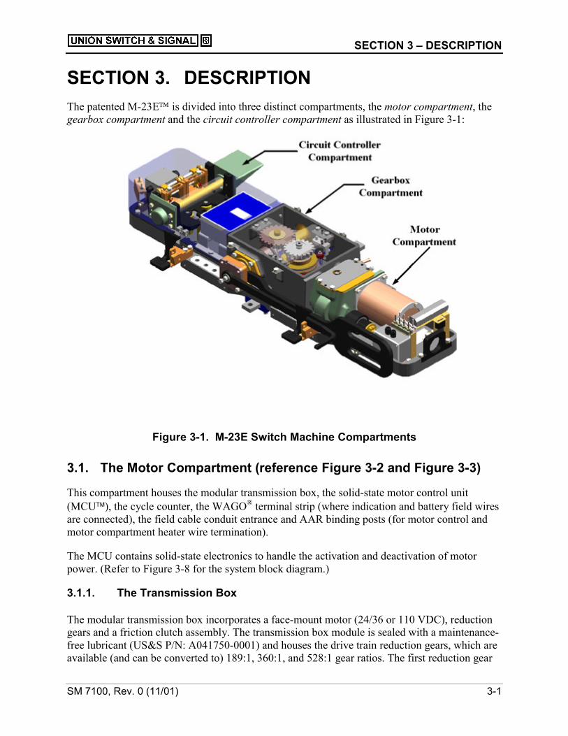
SECTION 3. DESCRIPTIONThe patented M-23E is divided into three distinct compartments, the motor compartment, thegearbox compartment and the circuit controller compartment as illustrated in Figure 3-1:
Figure 3-1. M-23E Switch Machine Compartments
3.1. The Motor Compartment (reference Figure 3-2 and Figure 3-3)
This compartment houses the modular transmission box, the solid-state motor control unit(MCU), the cycle counter, the WAGO® terminal strip (where indication and battery field wiresare connected), the field cable conduit entrance and AAR binding posts (for motor control andmotor compartment heater wire termination).
The MCU contains solid-state electronics to handle the activation and deactivation of motorpower. (Refer to Figure 3-8 for the system block diagram.)
3.1.1. The Transmission Box
The modular transmission box incorporates a face-mount motor (24/36 or 110 VDC), reductiongears and a friction clutch assembly. The transmission box module is sealed with a maintenance-free lubricant (US&S P/N: A041750-0001) and houses the drive train reduction gears, which areavailable (and can be converted to) 189:1, 360:1, and 528:1 gear ratios. The first reduction gear

3-2 SM 7100, Rev. 0 (11/01)
of each ratio combination is equipped with a bevel gear, which interacts with the hand-crankbevel gear providing hand-crank capability (with a 2:1 advantage over existing M-3 designs).Approximately 33 rotations of the hand-crank are required to move the machine from oneextreme position to the next.
Note that the selector lever must be in the “motor” position to operate the machine with thehand-crank.
3.1.1.1 Hand-crank Plunger Mechanism
The transmission box is also equipped with a hand-crank plunger mechanism, which ismonitored by a motor cutout proximity sensor. When the spring-loaded plunger is withdrawn toallow insertion of the hand-crank, the normally ON sensor turns OFF, disabling motor powerwithin the machine (indicated by the illumination of the red motor disabled LED on the ECC)and turning OFF all switch indication outputs.
3.1.2. Voltage
The MCU is available in both a low voltage (24/36VDC) and high voltage (110VDC)configuration, which must be matched to the type of motor selected.
3.1.3. Cycle Counter
A non-resettable cycle counter is installed in the motor compartment to assist in thedetermination of required maintenance frequency and to maintain a history of the machine’susage. The cycle counter tallies each complete cycle of the switch machine (i.e., the counterincrements each time the machine completes a cycle from normal to reverse and back normalagain). The counter cannot be reset so the operational history of the machine is preserved.
3.1.4. WAGO® Terminal Strip
The WAGO® terminal strip is the central termination point for ECC power and indication circuitconnections. It is where all field cables and wayside signal battery for the ECC are terminated.The ECC requires continuous 12 VDC battery feed from the wayside (800mA continuous currentdraw max.) There are fourteen (14) gas arrestors* mounted on the WAGO® terminals to protectthe ECC I/O lines from external lightning and power surges.
The ECC box is connected to the WAGO® terminal strip in the motor compartment with twoplug-coupled cables, TB1 and TB2. Both plug couplers are keyed differently so they cannot beinterchanged on the ECC box. The terminal strip is the integration point of the ECC systemwhere all field wires for switch indication and the wayside battery feed to the ECC system.(Refer to Figure 3-8 for the system block diagram.).
The WAGO® terminal strip is also the termination point for the machine’s cycle counter, thelocal/remote request switch option, and the two motor cutout sensors for disabling motor powerwhen manually operating the machine (by either hand-crank or the hand-throw lever).

SECTION 3 – DESCRIPTION
SM 7100, Rev. 0 (11/01) 3-3
3.1.5. Field Cable Conduit
The field cable conduit entrance is designed to accept a threaded, 2-1/2” NPT connection, whichcan be reduced to accommodate any watertight threaded conduit application.
3.1.6. AAR Binding Posts
The motor compartment is also equipped with an eight-way AAR binding post strip for field,motor power cable wires and motor control unit termination. Two of the AAR posts are strappedwith “gold nut” to disable motor power to the machine while allowing ECC signal battery topower the ECC for diagnostic analysis. These terminals are equipped with two (2) additional gasarrestors* to protect the MCU circuitry. (Refer to Figure 3-8 for the system block diagram.)
The MCU houses the high-powered FET electronic motor control circuitry. The FET circuitryturns OFF motor power at the end of each stroke only after the lock box in the machine is fullylocked (through the narrow notch).
*NOTEAll 16 of the gas arrestors (US&S PN: J7927360109) do not electricallyconnect the ECC or MCU I/O circuitry to the ground terminals. The gasarrestors are normally open to the I/O lines that they protect and will fireupon a local lightning strike, bringing the surge currents to the groundterminals instead of into the machine’s internal circuitry. The arrestorscan be fired multiple times, at high potentials, before their integrity isdegraded. A discoloration will occur so the fired arrestors will be highlydistinguishable.
3.2. The Gearbox Compartment (reference Figure 3-4 and Figure 3-5)This compartment houses the worm shaft/worm gear drive combination; the main-crank; topbearing and vertical, spring loaded clutch assembly that is used to enable either the motor (whenin the down position) or hand (when in the raised position) modes of operation. Transition fromone operational mode to the other is performed by the 180-degree rotation of the selector lever.
3.2.1. Gearbox Components and Assemblies
The worm gear-based drive train and main-crank configuration of the M-23E is based on thedesign of the M-23. While the new transmission box is modular in design, the worm shaft/wormgear ratio design is identical to that of the M-23. The 220-degree rotation of the main-crank inthe gearbox produces the timed operation of the operating bar and slide bar to throw andlock/unlock the machine, accordingly.
The vertical, spring-loaded clutch yoke assembly of the M-23E has been redesigned as a lowprofile unit to reduce the overall height of the gearbox. The clutch assembly was rotated 90degrees so disassembling the internal portion of the gearbox is no longer required to convert themachine from right hand to left hand (and vice versa). Gearbox conversion is easily achievedfollowing the steps outlined in Section 6.1.1 of this manual.

3-4 SM 7100, Rev. 0 (11/01)
Figure 3-2. Detailed View of the Motor Compartment Unit
Figure 3-3. Detailed View of Transmission Box

SECTION 3 – DESCRIPTION
SM 7100, Rev. 0 (11/01) 3-5
3.2.2. Motor Cutout Proximity Sensor
The top bearing or T-plate is equipped with a motor cutout proximity sensor that senses thevertical position of the clutch yoke target assembly. When the clutch yoke is raised by movingthe selector lever from the “motor” to the “hand” position” (after approximately 45 degrees ofrotation), the normally ON sensor turns OFF, disabling motor power within the machine andturning OFF all switch indication outputs.
3.2.3. Gearbox Configurations
US&S has configured the gearbox to operate in either a “full-locking” (M-23E-A) or “restrictivelocking” (M23E-B) hand-throw application. Refer to Section 4.2.1 describing the differencebetween the two gearbox configurations.
3.3. The Circuit Controller Compartment (see Figure 3-6 and Figure3-7)
This compartment houses the frog plate (controller frame), ECC, junction box, captive pointdetector system (CPDS), linear slides, local/remote control switches (optional), four vitalproximity sensors, and two non-vital auxiliary sensors (optional). See Figure 3-8 for ECC systemblock diagram and Section 3.3 for a detailed description of the ECC system integration.
CAUTIONExcessive heat may damage the Electronic Circuit Control (ECC).Heaters should not be placed in the circuit controller compartment.
3.3.1. Frog Plate
The frog plate is used as the base frame to mount the CPDS, linear slides, ECC box, junction boxand the vital proximity sensors. The modular frog plate can be replaced completely if damagedby dragging equipment.
3.3.2. Vital Locking Sensors
Two vital locking sensors are threaded into the frog plate casting and are used to determine thelinear position of the lock box. The locking sensors are in a fixed location to ensure complianceto FRA Rule 236.330. The locking sensors are also used to control the motor control unit (MCU)via the ECC to turn off motor power only after the lock dog on the lock box has fully engagedand extended beyond the narrow notch of the locking lock rod.
3.3.3. ECC Box
The ECC box houses a microprocessor and conditional power supply board, which are used todetermine the state of the switch machine and provide switch indication power to the outputs,respectively. The ECC provides advanced diagnostics to quickly determine the state of the

3-6 SM 7100, Rev. 0 (11/01)
Figure 3-4. Detailed View of Gearbox
Figure 3-5. Top View of Gear Box

SECTION 3 – DESCRIPTION
SM 7100, Rev. 0 (11/01) 3-7
machine and adjacent (daisy-chained) switch machine indication circuits. There is a momentarylatch-out restoration pushbutton on the front face of the ECC to manually restore a latch-outcondition when the ECC is configured in the manual or automatic restoration modes (via thejumper in the junction box).
3.3.3.1. AMP® Plug Couplers
The ECC uses three AMP® plug couplers. One coupler (designated as JB1) connects the ECC tothe junction box. The other two couplers (designated TB1 and TB2) connect the two 10-conductor cables, that run through the PVC conduit underneath the gearbox housing, and areterminated at the terminal strip in the motor compartment. The ECC is a sealed, non-serviceableunit and can be replaced simply by removing the four ½”-bolts securing the ECC adapter plate(attached to the bottom of the ECC box) and unplugging the three plug couplers. (See Figure 3-8for ECC system block diagram.)
3.3.4. Junction Box
The junction box, mounted directly to the end of the frog plate (furthest from the gearbox),provides termination for six proximity sensors through a six-way cable grip. In addition, thejunction box is equipped with two jumper configurations for determining the “normally closed”switch point (RHPC or LHPC) and latch-out options (manual, automatic, or disabled).
3.3.4.1. Jumper Configurations (See Figure 3-8)
The junction box, with two jumper configurations, provides the ECC box with information fordetermining which point is normally closed [left-hand point closed (LHPC) or right-hand pointclosed (RHPC)] and which type of latch-out configuration is selected (manual restoration,automatic restoration or latch-out completely disabled). Manual latch-out restoration is achievedby depressing the pushbutton on the ECC box for one second and releasing.
Note that a latch-out condition will only restore if all four vital proximity sensors indicate thatthe machine is fully locked and detected in one position.
3.3.4.2. Vital and Non-Vital Sensors (Optional)
The junction box is where the four vital sensors (two for point detection and two for lockingdetection) and two non-vital sensors are terminated via a six-way cable grip into the junctionbox. This termination method allows for convenient replacement of any individual sensor in thesystem. See Figure 3-8 for ECC system block diagram.
3.3.5. Captive Point Detection System (CPDS)
The captive point detection system (CPDS) consists of a self-lubricating bearing sleeve, whichcaptivates the point detector bar across the entire width of the machine. By not extending thepoint detector bar outside the field side of the machine, we eliminate any pinch-point safetyhazard with the hand-throw lever (which is now lower, due to the reduced profile of thegearbox).

3-8 SM 7100, Rev. 0 (11/01)
3.3.6. Point Detector Target
Attached to the captivated point detector bar is a ferrous metal, radial target used to activate theproximity sensors, with respect to switch point position. The target is fastened to the pointdetector bar with a ¼”-20 socket head cap screw that stays captivated by the sleeve. The end ofthe point detector bar extending outside of the machine on the trackside is rigidly connected tothe point detector connecting rod/lug. The point detector bars are available with two connectingend styles; 1”-8 threaded end for use with a drop lug and a 5/8” pin machined-end for use with aclevis lug.
3.3.7. Linear Slides
The linear slides are used to secure and provide adjustment of the proximity sensors with respectto the point detector target on the point detector bar. There are two linear slides, one for eachposition of the switch point. Each linear slide is equipped with a vital proximity sensor (18mmdiameter) and a non-vital, auxiliary proximity sensor (8mm diameter). Adjustment of the linearslides is accomplished by loosening the ½” bolt at the top of the slide and rotating the thumbwheels accordingly. The thumb wheels rotate a ½”-20 threaded rod; therefore, one full rotationof the thumb wheels results in a 0.050” linear displacement of the proximity sensors, parallel tothe point detector bar.
3.3.8. Vital Sensor Position Monitoring
The state (ON, OFF, SHORTED or OPEN) of each vital sensor is continuously monitored by theECC processor every 50 milliseconds. The vital sensor’s position is adjusted with respect to thepoint detector target’s position, to detect a defined linear change in position of the target (forexample: a ¼” obstruction in the switch point).
3.3.9. Non-Vital Auxiliary Sensors (when Included)
Like the vital sensors, the non-vital auxiliary sensors also monitor the point detector target’sposition, but their sensing range is mechanically offset by approximately 1/8”. This enables theauxiliary sensors to detect target movement before vital sensor detection. When the auxiliarysensors are no longer sensing the target, a normally ON auxiliary bipolar output on the WAGO
terminal strip becomes de-energized. This feature is used to predict switch failures. As anexample, if the vital sensor is adjusted to detect a ¼” obstruction in the switch points, the targetmust be displaced by that same distance before the vital sensors changes from the ON to the OFFstate. The nonvital sensor, however, changes from the ON to the OFF state after an approximate1/8” displacement in linear target position. This can be used to indicate that the machine movedmarginally and is on the verge of failure (i.e., the switch points have moved due to temperatureor the point is still closing but is being gradually obstructed by an element such as sand, ice,etc.).
3.3.10. Local/Remote Request Switches
The local/remote request switches are used to locally operate the machine, similar to that of awayside local control panel. One toggle switch is used to take local or remote control and theother toggle switch is used to cycle the machine from normal to reverse and back, in the localcontrol mode of operation.

SECTION 3 – DESCRIPTION
SM 7100, Rev. 0 (11/01) 3-9
Figure 3-6. Controller Compartment
Figure 3-7. Controller Compartment with Sensor View

3-10 SM 7100, Rev. 0 (11/01)
JUNCTION BOX
SENSOR TERMINALS +LHPC/RHPC & LATCH OUT OPTION
JUMPER CONFIGURATIONS
PS1
PS2
LS1
L
2
AUX1
AUX2
ECC BOXMICROPROCESSOR & POWER SUPPLY,
DIAGNOSTIC LED DISPLAY + LATCH OUTRESTORATION PUSHBUTTON
LATCH OUT RESTORATION
TB1 TB2 JB1
VITAL POINTSENSORS
VITAL LOCKINGSENSORS
AUXILLIARY POINTSENSORSLOCAL REMOTE
REQUESTSWITCHES
CYCLECOUNTER
TERMINALBOARD &BINDINGPOSTS
FIELD CABLE AND WAYSIDEBATTERY FOR ECC
MOTOR CONTROL UNIT(MCU)
HIGH POWER FET SWITCHES
MOTOR
CIRCUIT CONTROLLER COMPARTMENT
MOTOR COMPARTMENT
HANDTHROW
HANDCRANK
IN GEARBOX
MOTOR CUTOUTSENSORS FOR
MANUALOPERATION
Figure 3-8. M-23E ECC System Block Diagram

SECTION 4 – OPERATION
SM 7100, Rev. 0 (11/01) 4-1
SECTION 4. OPERATION4.1. General Overview
By definition, a mainline dual-control switch machine can be operated under power or with theuse of a manual 180-degree hand-throw lever. The M-23E, like its predecessor the M-23, isavailable with both of these dual control functions. In addition, the M-23E can also be operatedwith a manual hand-crank. The transmission box is equipped with a hand-crank opening andmotor cutout plunger for manual operation protection. The ¾” hex crankshaft in the transmissionbox is designed so a standard ¾” socket also can be used to move the mechanism.
4.1.1. “Power” Operation
Under “power” operation, the worm shaft/worm gear combination is driven by a series ofreduction gears powered by the motor (reduction gears can be any one of three gear ratiocombinations: 189:1, 360:1 or 528:1).
4.1.2. “Manual” Operation via the Hand-Throw Lever
Under “manual” operation via the hand-throw lever (the selector lever must be in the Handposition), rotation of the hand-throw lever directly drives a combination gear below the T-plate,which in turn directly rotates the main-crank via the vertical clutch assembly. Rotation of themain-crank results in the horizontal movement of both the slide bar and operating bar.
4.1.3. “Manual” Operation via the Hand-Crank
Under “manual” operation via the hand-crank (the selector lever must be in the Motor position),the hand-crankshaft in the transmission box drives the last reduction gear via a 1:1 bevel gearcombination. The driving of the reduction gears rotates the worm shaft/worm gear combinationultimately resulting in rotation of the main-crank via the vertical clutch assembly. With allreduction gear combinations (189:1, 360:1 and 528:1) the hand-crank operates on a 2:1 gear ratioto the worm shaft (i.e., two rotations of the hand-crank results in one rotation of the worm shaft).
4.1.4. Main-Crank Rotation
The lobes on the top of the lower main-crank flange interact with the rollers on the slide bar,moving the slide bar linearly along the length of the machine to unlock the lock rods. Just beforethe slide bar stops moving, the lower hub and roller on the bottom of the main-crank flangebegins to drive the operating bar. The operating bar moves through a 6” stroke, moving theswitch points to the opposite position. Just before the operating bar stops moving, completing thepoint closure, the slide bar begins to move again to begin locking the machine in the oppositeposition.

4-2 SM 7100, Rev. 0 (11/01)
4.1.5. ECC Monitoring
The ECC continually monitors the state of the machine, reporting the transition of the machinefrom one position to the other. Switch indication circuits are OFF when the machine is in transitand the circuits are shunted for additional safety precaution.
4.2. MANUAL OPERATION
4.2.1. Hand-Throw Lever Operation
Move the selector lever to the HAND position and secure the lever accordingly into the latchstand. Rotate the hand-throw lever. If the operating bar does not move with this motion, continueto move the hand-throw lever through the entire 180-degree rotation until the vertical clutchassembly “snaps” into place. The alignment of the clutch will produce a rather loud sound, whichis perfectly normal. Once the vertical clutch assembly is engaged, the hand-throw lever willmove the operating bar accordingly.
4.2.1.1. Alternate Hand-Throw Pinion Gears
If the machine is an M-23E-A (i.e., is equipped with an “A” hand-throw pinion gear), themachine will fully lock in the hand-throw mode. Refer to Figure 4-1 illustrating A/B gearcomparison.
If the machine is an M-23E-B (i.e., is equipped with an “B” hand-throw pinion gear), themachine will NOT fully lock in the hand-throw mode. Refer to Figure 4-1 illustrating A/B gearcomparison.
Figure 4-1. Alternate Hand-Throw Pinion Gears

SECTION 4 – OPERATION
SM 7100, Rev. 0 (11/01) 4-3
4.2.1.2. M-23E-A / M-23E-BThe difference between the M-23E-A machine and the M-23E-B machine is one gear.
The hand-throw pinion gear on an M-23E-B machine is cut away from 180 degrees to 118degrees (refer to Figure 4-1 for the A/B gear comparison), which limits the movement of theslide bar. The pinion gear in an M-23E-A machine is not cut away, therefore allowing the slidebar to travel its full stroke in the hand-throw mode.
With an “A”-gear gearbox configuration, the lock dog on the lock box will fully enter the narrownotch on the lock rods, allowing full indication of the machine. With a “B”-gear gearboxconfiguration, slide bar movement is restricted; therefore, the lock dog on the lock box will notengage the lock rods.
Switch indication cannot be achieved with the hand-throw lever on a “B”-style machine. Thesegears can easily be interchanged simply by removing the six (6) ½” bolts securing the T-plateand replacing the gear. (Refer to Figure 4-1.)
4.2.1.3. Hand-Throw Lever Rotation
Total rotation of main-crank in the M-23E is 220 degrees in the power (motor) mode, 216degrees in an “A” gear application and 154 degrees in the “B” gear application. In all M-23Emachines (A or B) the upper clutch cup is cut two degrees on either side (176 degrees of stockremaining) to provide proper alignment of the vertical clutch assembly when transferring fromthe motor- to hand-mode of operation.
On an M-23E-A style machine, if the lock rods are out of adjustment and the lock dog on thelock box obstructs the lock rod (instead of entering the locking notch), it will not be possible torotate the hand-throw lever a full 180 degrees and secure the lever into the latch stands..
4.2.2. Hand-Crank Operation
Hand-crank operation is performed with the selector lever in the “MOTOR” position.
Retract the plunger on the top of the transmission box and insert the hand-crank onto thecrankshaft. Prior to operating the hand-crank, ensure that the motor disabled LED is illuminatedon the ECC and that the hand-crank or socket is fully seated on the hex crankshaft.
4.2.2.1. Hand-Crank Rotation
The machine will crank from one extreme, locked position to the other with approximately 33rotations of the hand-crank.
4.3. POWER OPERATIONWhen the M-23E is operated under power, the following sequence of events will occur:
• Turn OFF switch indication
• Unlock machine

4-4 SM 7100, Rev. 0 (11/01)
• Throw to opposite position
• Lock opposite position
• Turn ON switch indication if the machine is locked and detected in that position.
4.3.1. Power (Motor) Operation
When operating the machine under power, energy is applied to the AAR binding posts 1 and 4,and the motor begins to rotate. The motor drives the reduction gears in the transmission boxthrough either a 189:1, 360:1, or 528:1 gear ratio (depending on the application). The reductiongears drive the clutch gear on the worm extension shaft and in turn rotates the worm shaft. Therotation of the worm shaft rotates the worm gear, directly driving the main-crank through thevertical clutch assembly.
4.3.1.1. Power Mode Main-Crank Rotation
In the power mode of operation, the main-crank rotates 220 degrees from one fully lockedposition to the other. (See also Subsection 4.2.1.3 for hand-throw arm rotation.)
4.4. ECC OPERATION AND MONITORING
The ECC system is functionally equivalent to that of the US&S N285638 circuit controllermechanism, but has no mechanical contacts or cam arrangements. The MCU emulates the motorcutout contacts from the mechanical controller in that it is continuously set up to move themachine to the opposite direction when in the full Normal or Reverse positions. This MCUprovides the same “make-before-break” motor control circuitry as in the existing M-3/M-23controllers.
4.4.1. Proximity Sensors
All proximity sensors used in the ECC system, vital and non-vital, are active underNORMALLY ON conditions. In other words, no logic condition of the ECC is dependent uponthe point detection, locking, auxiliary or even motor cutout sensors being OFF to make adecision. The only time the OFF-state of the sensors is relevant is when determining the lockedand detected position of the machine. In order for switch indication to be energized, for example,in the normal position, both the normal point and lock sensors must be ON and the reverse pointand lock sensors must be OFF.
4.4.2. Vital Point and Lock Sensors
The vital point and lock sensors work in predetermined pairs; and each of the two-paired sensors,one point and one lock, are “ANDED” (linked) together. In other words, in order to receive anormal switch indication output from the ECC, both the point and lock sensors for the normalposition must both be energized or ON. The same is true for both point and lock sensors for thereverse position. If either one of the two paired sensors are OFF, in either switch position, theswitch indication output is OFF for that position. The paired sensors are labeled PS1 & LS1 andPS2 & LS2, and work together, respectively. The pair of sensors which corresponds to the
SECTION 4 – OPERATION
SM 7100, Rev. 0 (11/01) 4-5
normal position is dependent upon the position of the LHPC/RHPC jumper position in thejunction box.
When the machine is locked and the points are detected in either the normal or reverse positions(illustrated by the point detected and point locked LEDs) and the corresponding indication inputis present or energized, the indication output LED for that switch position will be illuminated onthe ECC. This is a direct confirmation that indication power (~12VDC) is leaving the machine.
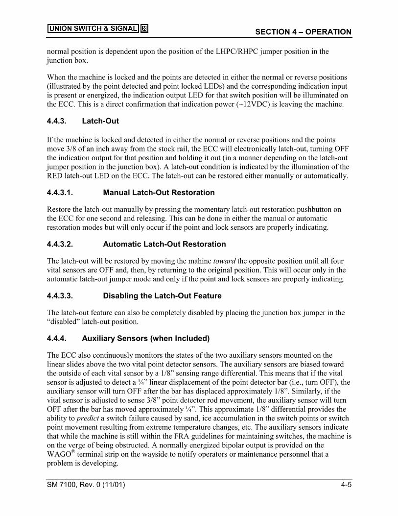
4.4.3. Latch-Out
If the machine is locked and detected in either the normal or reverse positions and the pointsmove 3/8 of an inch away from the stock rail, the ECC will electronically latch-out, turning OFFthe indication output for that position and holding it out (in a manner depending on the latch-outjumper position in the junction box). A latch-out condition is indicated by the illumination of theRED latch-out LED on the ECC. The latch-out can be restored either manually or automatically.
4.4.3.1. Manual Latch-Out Restoration
Restore the latch-out manually by pressing the momentary latch-out restoration pushbutton onthe ECC for one second and releasing. This can be done in either the manual or automaticrestoration modes but will only occur if the point and lock sensors are properly indicating.
4.4.3.2. Automatic Latch-Out Restoration
The latch-out will be restored by moving the mahine toward the opposite position until all fourvital sensors are OFF and, then, by returning to the original position. This will occur only in theautomatic latch-out jumper mode and only if the point and lock sensors are properly indicating.
4.4.3.3. Disabling the Latch-Out Feature
The latch-out feature can also be completely disabled by placing the junction box jumper in the“disabled” latch-out position.
4.4.4. Auxiliary Sensors (when Included)
The ECC also continuously monitors the states of the two auxiliary sensors mounted on thelinear slides above the two vital point detector sensors. The auxiliary sensors are biased towardthe outside of each vital sensor by a 1/8” sensing range differential. This means that if the vitalsensor is adjusted to detect a ¼” linear displacement of the point detector bar (i.e., turn OFF), theauxiliary sensor will turn OFF after the bar has displaced approximately 1/8”. Similarly, if thevital sensor is adjusted to sense 3/8” point detector rod movement, the auxiliary sensor will turnOFF after the bar has moved approximately ¼”. This approximate 1/8” differential provides theability to predict a switch failure caused by sand, ice accumulation in the switch points or switchpoint movement resulting from extreme temperature changes, etc. The auxiliary sensors indicatethat while the machine is still within the FRA guidelines for maintaining switches, the machine ison the verge of being obstructed. A normally energized bipolar output is provided on theWAGO® terminal strip on the wayside to notify operators or maintenance personnel that aproblem is developing.

4-6 SM 7100, Rev. 0 (11/01)
NOTESensor adjustment should be factory set and should not have to be set inthe field. If field adjustment is needed, adjust the vital sensor until the“Point Detector” of the ECC LED turns on. Turn the adjusting wheel 4turns so the vital sensor is farther in front of the target. At this point, turnthe adjusting wheel in the opposite direction. The non-vital sensor shouldbe set to turn off between 2 and 3 turns. This will set the non-vital sensorto turn off at approximately 1/8” as the point moves away from the stockrail.
The gap between the target and the sensor should be approximately0.040”.
4.4.5. Manual Operation Motor-Cutoff Protection
Manual operation motor-cutoff protection is provided with the use of two-8mm diameterinductive proximity sensors. One sensor is located in the gearbox and continuously monitors thevertical position of the spring-loaded clutch yoke assembly. When the selector lever is releasedfrom the latch stand and rotated 45 degrees, the normally ON sensor turns OFF and the ECCdisables the MCU. The same is true for the hand-crank operation, in that the second sensor iscontinuously monitoring the horizontal position of the plunger assembly on the transmission box.When the plunger rod is extracted ¼”, the normally ON sensor turns OFF and the ECC disablesthe MCU, accordingly.
CAUTIONALTHOUGH THE MOTOR CUTOUT PROXIMITY SENSORS DISABLETHE MOTOR POWER FOR MANUAL OPERATION, IT IS STRONGLYRECOMMENDED THAT THE “GOLD NUT” IN THE MOTORCOMPARTMENT BE OPENED BEFORE PERFORMING WORK ONOR INSIDE THE MECHANISM TO PREVENT POSSIBLE INJURY. THEGOLD NUT MUST BE OPENED TO PREVENT THE MACHINE FROMTHROWING.
4.5. ECC DIAGNOSTIC INFORMATION
4.5.1. LEDs
The ECC is equipped with a series of LEDs to indicate the current state of the switch machine.Dual-colored LEDs are provided to indicate the state of each vital point and lock sensor. GreenLEDs are provided for indication input, indication output and auxiliary sensor state definition.Red LEDs are provided to determine when the motor is disabled and when the ECC is in alatched-out state.
Table 4-1 describes what the ECC diagnostics represent.

SECTION 4 – OPERATION
SM 7100, Rev. 0 (11/01) 4-7
4.5.2. Vital Sensor Monitoring and Led Diagnostic Representation
The ECC continuously monitors the state of each vital point and lock sensor in the machine. Byanalyzing the current draw of the sensors, it can determine if the sensor is ON, OFF orINDETERMINATE. INDETERMINATE can mean the sensor is open, shorted or between therange of ON and OFF.
Table 4-1. LED Diagnostics
GREEN Sensor On
RED Sensor OffPointDetected
FLASHING RED Indeterminate
GREEN Sensor On
RED Sensor OffPointLocked
FLASHING RED Indeterminate
GREEN Indication input power present from adjacent machineIndicationInput DARK No indication power present
GREEN Switch is locked and detected/indication output is onIndicationOutput DARK Switch is not locked and detected/indication output is off
GREEN Aux. Sensor on / aux. bipolar output is onAuxiliaryPointDetected DARK Aux. Sensor off / aux. bipolar output is off
RED Latched outLatch-out
DARK Not latched out
RED Motor power disabledMotorDisabled DARK Motor power enabled
4.5.3. Diagnostic Modes of Dual-Colored LEDs
As illustrated in Table 4-1, the dual-colored LEDs that represent the states of the vital point andlock sensors have three possible diagnostic modes: green, red, or flashing red.
Green simply means the sensor is ON and is detecting its specified target. Red means the sensoris OFF and not sensing the target. In order to definitively distinguish between an ON and an OFFsensor state, an indeterminate operating window is used between the two states, flashing red. Asthe target approaches the sensor, the sensor will change from the OFF state to anINDETERMINATE state and then to the ON state. The LED will represent this by changingfrom red to flashing red and then to green. During normal switch operation, this transition willnot be noticeable.

4-8 SM 7100, Rev. 0 (11/01)
.

SECTION 5 – WIRING AND MOTOR CONTROL
SM7100, Rev. 0 (11/01) 5-1
SECTION 5. WIRING AND MOTOR CONTROL5.1. WAGO® Terminal strip Connections (See Figure 5-3)
Terminals 2, 5, 8, 11, 14, 18, and 22 are internally connected to the DIN rail and serve as ameans by which the 14 gas lightning arrestors make contact with the base of the machine forgrounding purposes.
NOTETo maintain operability no other wires should be terminated to theseterminals.
5.1.1. Terminals 1 and 3: Two-Wire, Bipolar Indication Output Circuit
Terminals 1 and 3 are for field connections to a two-wire, bipolar indication output circuit.
5.1.1.1. Normal Indication
Normal indication is defined as (+) on terminal 3 and (-) on terminal 1.
5.1.1.2. Reverse Indication
Reverse indication is defined as (-) on terminal 3 and (+) on terminal 1.
5.1.1.3. No Output
If there is no output, terminals 1 and 3 are shunted.
5.1.2. Terminals 4, 6, 7, and 9: Four-Wire Indication Output Circuit
Terminals 4, 6, 7, and 9 are for field connections to a four-wire indication output circuit.
5.1.2.1. Normal Indication
Normal indication is defined between terminals 7 (negative) and 9(positive).
5.1.2.2. Reverse Indication
Reverse indication is defined between terminals 4 (negative) and 6 (positive).
5.1.2.3. No Output
If there is no output on the paired terminals, they are shunted.

SECTION 5 – WIRING AND MOTOR CONTROL
5-2 SM 7100, Rev. 0 (11/01)
5.1.3. Terminals 10, 12, 13 and 15: Indication Input
Terminals 10, 12, 13 and 15 are for indication input field connections from an adjacentmachine’s indication output circuit or can be jumpered in the application of a single machine.
5.1.3.1. Normal Indication
Normal indication input is defined between terminals 13 (negative) and 15 (positive).
5.1.3.2. Reverse Indication
Reverse indication input is defined between terminals 10 (negative) and 12 (positive).
5.1.3.3. Indication Output
If the machine is used in a single machine application, the battery must be fed to the indicationinput circuits to provide indication output. Refer to wiring diagram illustrated in Figure 5-3 forproper jumper configuration.
WARNINGFour indication-input jumpers are factory installed on the WAGO®terminal strip and must be removed for multiple-machineapplications.
5.1.4. Wayside Battery Connections
Terminal 17 is used for connecting wayside battery N12. Terminal 20 is used for connectingwayside battery B12.
Note that there are factory installed jumpers between paired terminals 16 and 17 and betweenpaired terminals 19 and 20. Wayside battery can be fed to either available terminal of each pair.
5.1.5. Bipolar Auxiliary Sensor Output
Terminals 21 and 23 are for field connections to the two-wire, bipolar auxiliary sensor output.
5.1.5.1. Normal Auxiliary Indication
Normal auxiliary indication is defined as (+) on terminal 23 and (-) on terminal 21.
5.1.5.2. Reverse Auxiliary Indication
Reverse auxiliary indication is defined as (-) on terminal 23 and (+) on terminal 21.

SECTION 5 – WIRING AND MOTOR CONTROL
SM7100, Rev. 0 (11/01) 5-3
WARNINGThe maintenance output is NOT VITAL and should never be used toclear signals.
5.1.6. Local/Remote Request Switch Option
Terminals 20, 24, 25, and 26 are for field connections to use the local/remote request switchoption. This function is beneficial--particularly when conducting monthly inspections. In orderfor this function to work, however, the wayside must be configured properly.
The two toggle switches in the machine (L/R and N/R) interface with the local control panel,providing the ability to control the machine as though operating directly from the local controlpanel. Normally, the local/remote (L/R) switch is to be in the remote position. When placed inthe local position, battery + is routed to terminal 26. The local control panel is thus activated toreceive commands from maintenance personnel at the machine. The second switch (N/R) is acenter-OFF, spring-return toggle. When held in the N position, the machine is electrically drivenfrom the wayside controller to the normal position. If the switch is released before the stroke iscomplete, the motor will coast to a stop.
WARNINGThe LOCAL REQUEST will override the dispatches’ control of themachine. It is important to return the LOCAL REQUEST switch tothe REMOTE position upon completion of maintenance to returncontrol of the machine to the dispatcher.
5.1.7. Motor Control Unit and Cycle Counter Termination
Terminals 27 through 31 are for termination of the motor control unit (MCU) and are also usedto terminate the cycle counter.
5.1.7.1. Motor Control
ON MOTOR FRONT and ON MOTOR REAR are used to turn off motor current at the end ofthe stroke. For example, if the motor is turning to produce motion of the lock box toward themotor compartment (front end of the machine), both ON MOTOR FRONT and ON MOTORREAR are +, relative to GND. When lock sensor LS2 turns ON, the ON MOTOR FRONT lineswitches to GND. In response, the motor controller opens the motor to the polarity of current thatwould continue motion in the same direction. Additionally, the counter is energized momentarilyand one count is registered. Operation in the opposite direction is the same with ON MOTORREAR switching to stop the motor; however, the counter does not respond.

SECTION 5 – WIRING AND MOTOR CONTROL
5-4 SM 7100, Rev. 0 (11/01)
TROUBLESHOOTING TIPNormally, there should be no need to measure voltage on the WAGO®
terminal strip because LEDs on the ECC accurately display voltages at thestrip. The one exception is if the connection to the strip is open. If there isreason to make a measurement, do not use battery (-) as a reference, thevoltages on the strip are not referenced to battery: they are isolated from it.
5.1.8. Motor Cutout Circuits Termination Points
Terminals 32 through 34 are the termination points for the motor cutout circuits. In an M-23E,this is the termination point for the hand-throw and hand-crank motor cutout proximity sensors.In an M-23E upgraded with an ECC, the existing motor cutout contact in the circuit controllercompartment is to be connected to terminals 32 and 33. An 820-ohm resistor is series connectedin the circuit to disable motor power when the selector lever is actuated for hand-throwoperation.
5.1.9. MCU Test Procedure
Perform the following test on the MCU unit to validate safe operation.
1. Open the gold nut to disconnect the motor.
2. Remove the field wires on terminals 1 and 3 to disconnect motor power from thehouse.
3. Connect a 100-ohm resistor or signal lamp across terminals 3 and 4. (This may not benecessary if an analog meter is being used to make subsequent measurements.)
4. Connect a voltmeter across terminals 3 and 4.
5. Connect battery (either polarity) to terminals 1 and 3.
6. The meter will read either 0 or 12 volts (if. the machine is locked either normal orreverse).
7. Reverse the previous battery polarity. (If the previous reading was 12 volts it shouldnow read 0; if the previous reading was 0 it should now read 12.)
8. Restore the polarity to achieve a 12-volt reading.
9. Lift the selector lever and confirm the reading is 0.
10. Manually throw the machine to the opposite position and confirm that the meterremains at 0.

SECTION 5 – WIRING AND MOTOR CONTROL
SM7100, Rev. 0 (11/01) 5-5
11. Restore the hand/motor handle to motor and confirm that the meter reading remains at0 .
12. Reverse battery polarity, and the meter should now read 12 volts.
5.2. AAR Terminal Post Connections
There are eight AAR binding post terminals labeled 1 through 8.
Terminal 1 is the termination point for the red MCU control wire, one of the two field motorcontrol wires, and a gas tube arrestor used for lightning protection.
Terminals 2 and 3 are common terminals used for grounding purposes and termination of the gasarrestors which are connected to terminals 1 and 4.
Terminal 4 is the termination point for the second field motor control wire and is also used formounting a gas tube arrestor for lightning protection.
Terminal 5 is the connection point for the jumpers to Terminals 4 and 6.
Terminal 6 is the termination point for the negative motor terminal. A “gold nut” test link isprovided between Terminals 5 and 6 to disconnect motor power when performing maintenanceon the machine.
Terminals 7 and 8 are designated for motor compartment, heater wire termination.
5.3. Sensor Identification and Termination in the Junction Box
The vital point detector sensors are designated PS1 and PS2. The vital locking sensors aredesignated LS1 and LS2. The auxiliary point detector sensors are designated Aux1 and Aux2. Itis important to note that PS1 and LS1 always work in combination together, while PS2 and LS2always work together as well. Refer to Figure 5-1.
The four vital and two non-vital auxiliary sensors are all terminated inside the junction boxlocated on the rear of the frog plate. All six sensor wires are brought into the junction boxthrough a 6-way cable grip, and their brown and blue wires are terminated in WAGO® cageclamp connectors. The PC board inside the junction box identifies which sensors connect to eachterminal and the color designation of each sensor wire (BR for BROWN and BU for BLUE). Ifany of the four vital sensors are wired incorrectly, the corresponding LEDs on the ECC will flashRED. If the auxiliary sensors are wired incorrectly, they will not operate. There is a yellow LEDon the back end of each auxiliary sensor to indicate proper operation.

SECTION 5 – WIRING AND MOTOR CONTROL
5-6 SM 7100, Rev. 0 (11/01)
Figure 5-1. Top View-Controller Compartment
5.4. 3- and 5-Wire Control Conversion to 2-Wire Control (See Figure5-2)
The following diagram illustrates a typical 3- and 5-wire control relay scheme converted to therecommended 2-wire control system. Conversion from a 5- to 2-wire configuration is best suitedfor changes in the wayside house or bungalow. Conversion of 3- to 2-wire control can beperformed at the wayside location or in the machine using the spare AAR terminal posts toconnect two of the three wires together as shown.

SECTION 5 – WIRING AND MOTOR CONTROL
SM7100, Rev. 0 (11/01) 5-7
Figure 5-2. Wiring Changes from 3-Wire and 5-Wire to 2-Wire Motor Control
Wiring Changes From 3 Wire and 5 Wire to 2 Wire Motor Control
Connect together and return to N24for 2 Wire Control
Eliminate for 2 Wire Control
N24
B24 R
NB24
N
R
N24
R
N
RB24
N
R
B24 R
B24 N
N24 N
B24
N24
N
R
B24
R
N
N24
N24
R
NB24
Connect Togetherfor 2 wire control
Field
Observe Polarity Convention
Retrofit of M23 with ECCRatio and M23E orConsistent with Gear
1
2
Symbols
M23E or M23 with ECC Retrofit
5
4
2
3
For 5
Wire
to 2
Wire
Con
vers
ion
Normal & ReverseMotor Cut-Out
Hand ThrowMotor Cut-Off
TO
FROM
Observe Polarity Convention
Retrofit of M23 with ECCConsistent with GearRatio and M23E or
M23E or M23 with ECC Retrofit
5 Wire Wound Field Motor1
2
1
2
3
1
3 Wire PM Motor
For 3
Wire
to 2
Wire
Con
vers
ion
TO
FROM

SECTION 5 – WIRING AND MOTOR CONTROL
5-8 SM 7100, Rev. 0 (11/01)
M23
E In
tern
al W
iring
Dia
gram
34 33 32 2831 30 29 27 26 25 24 23 22 21 20 19 18 17 16 15 14 13 12 11 10 9 8 7 6 5 4 3 2 1
820
Slat
e
Blue
Viol
et
Whi
te
Brow
n
Red Bl
ack
Gre
en
Yello
w
Blac
k
Slat
e
Yello
w
Blue
Red
Gre
en
Whi
te
Ora
nge
Viol
et
Brow
n
4
Loca
l
Rem
ote
Nor
mal
Rev
erse
2 31
2
View
A- P
roxi
mity
Sen
sor L
ayou
t & Id
entif
icat
ion
Mot
or E
nd
Poi
nt S
enso
r 1Au
xilia
ry S
enso
r 1
Poin
t Sen
sor 2
Auxi
liary
Sen
sor 2
Lock
Sen
sor 1
Lock
Sen
sor 2
Poi
ntS
enso
r 1
Poi
ntS
enso
r 2
Lock
Sen
sor 1
Lock
Sen
sor 2
Aux
iliary
Sen
sor 1
Aux
iliary
Sen
sor 2
Junc
tion
Box
N42
4001
02
3 3 3 3
3 3H
and
Thro
w S
enso
r
Han
d C
rank
Sen
sor
Bro
wn
Bro
wn
Blue
Blue
Cou
nter
Bla
ck
Red
Mot
or C
ontro
l Uni
tN
4730
39-0
3(hi
gh v
olta
ge)
UNION SWITCH & SIGNAL ECC
1. A
ssem
ble
per E
U-8
558.
All
part
num
bers
are
cal
led
o
ut in
the
spec
ifica
tion.
Con
nect
ions
as
show
n to
WA
GO
term
inal
s 29
(wire
1)
and
to W
AGO
term
inal
30
(wire
2) a
re c
orre
ct fo
r mot
ors
with
a 1
89:1
gea
r rat
io.
For m
otor
s w
ith a
360
:1 g
ear r
atio
w
ire 1
is c
onne
cted
to W
AGO
term
inal
29
and
wire
2 is
co
nnec
ted
to W
AGO
term
inal
30.
3.
See
view
A fo
r loc
atio
ns o
f sen
sors
. R
efer
to D
497-
SH.0
10
for
sen
sor c
onne
ctio
ns in
side
of t
he ju
nctio
n bo
x.
PointDetectedPointDetectedPointLockedPointLocked
IndicationInputIndicationInputIndicationOutputIndicationOutput
AuxiliaryPointDetectedAuxiliaryPointDetectedLatchOut
MotorDisabled
LEDDiagnostics
UNIONSWITCH&SIGNALECC
TB1TB2JB1
LatchOutRestoration(Pressfor1SecondandRelease)
N47
3034
01
WA
RN
ING
Mai
nten
ance
Bi-P
olar
Ter
min
als
21 a
nd 2
3 ar
e N
on-V
ital a
nd s
houl
dne
ver b
e us
ed to
cle
ar s
igna
ls.
Mai
nten
ance
Bi-P
olar
(Nor
mal
+)
Mai
nten
ance
Bi-P
olar
(Nor
mal
-)
Bat
tery
Inpu
t + (B
12)
Bat
tery
Inpu
t - (N
12)
Nor
mal
Inpu
t +
Nor
mal
Inpu
t -
Rev
erse
Inpu
t +
Rev
erse
Inpu
t -
Nor
mal
Out
put +
Nor
mal
Out
put -
Rev
erse
Out
put +
Rev
erse
Out
put -
Bi-P
olar
(Nor
mal
+)
Bi-P
olar
(Nor
mal
-)
Loca
l Req
uest
Nor
mal
Req
uest
Rev
erse
Req
uest
Gro
und
Term
inal
Gro
und
Term
inal
Gro
und
Term
inal
Gro
und
Term
inal
Gro
und
Term
inal
Gro
und
Term
inal
Gro
und
Term
inal
1 2 3 4
Yel/G
rn
Mot
or18
45
Gol
d N
ut
Whi
te
Red
Blac
k
Earth
Gro
und
+
110V
Mac
hine
Fram
e
AAR
Ter
min
al B
lock
Per
man
ent M
agne
t Mot
or C
onfig
urat
ion
4
Hea
ter
Term
inal
s
2. 4.In
dica
ted
pola
rity
driv
es p
oint
s rig
ht (S
ee V
iew
A).
Figure 5-3. Internal Wiring Diagram

SECTION 6 – INSTALLATION AND SETUP
SM7100, Rev. 0 (11/01) 6-1
SECTION 6. INSTALLATION6.1. Component Conversion - Right- to Left-Hand (and vice versa)
6.1.1. Gearbox Conversion
This procedure explains conversion of the gearbox from one-hand throw to the other:
WARNINGPROPER LIFTING PROCEDURES SHOULD BE FOLLOWED TOMINIMIZE THE RISK OF INJURY.
The hand-throw lever assembly weighs approximately 72 poundsand should not be lifted by one individual.
1. Place the hand-throw lever on the controller side of the machine and the selector lever on themotor side of the machine.
2. Being careful not to withdraw the assembly or any portion of it out of the machine, removethe two lower ½” bolts (2-3/4” long) from the hand-throw lever assembly.
3. Carefully spin the hand-throw lever support (illustrated in Figure 3-4 and
4. Figure 3-5) 180 degrees around the center of the hand-throw lever assembly shaft. This willlocate the internal ball bearing so that it is always oriented toward the controller side of themachine.
5. Replace the two lower ½” bolts back into the hand-throw lever assembly, inserting them onlyabout half way into the assembly, leaving approximately ½” length of the bolt shoulderexposed.
6. Remove all four of the top ½” bolts (1-½” long) from the hand-throw lever assembly.
Note that removal of the upper two bolts with a ratchet can be achieved by placing the 1”long socket over the bolt head and inserting the 3/8” drive extension through the hand-throwlever support and into the end of the socket.
7. Rotate both the hand-throw lever and the selector lever to the full vertical position. At thispoint, the punched timing marks on the combination and A/B gear should be visible throughthe T-plate timing mark window, illustrated in
8. Figure 3-5.
Withdraw the hand-throw lever assembly from the gearbox housing.

SECTION 6 – INSTALLATION AND SETUP
6-2 SM 7100, Rev. 0 (11/01)
7. Remove the four ½” bolts (1-½” long) from the blind side cap (illustrated in Figure 3-4) andwithdraw from the gearbox housing. The eccentric shaft will still be inserted into the blindside cap and should be withdrawn along with the cap. End-to-end orientation of the eccentricshaft is not critical.
8. Reinstall the blind side cap on the opposite side of the gearbox and secure with the four ½”bolts removed in the previous step. After reinstalling the cap, rotate the eccentric shaft so thecenter eccentric pin is in the horizontal or mid-stroke position facing toward the main-crank.
9. Remove the two latch stand assemblies and install them on the opposite side of the machine.
10. While holding the hand-throw and selector levers in the vertical position, insert the hand-throw lever assembly into the gearbox housing. Make sure the gear timing marks are stillvisible in the T-Plate window and the eccentric shaft is still in the orientation described inStep 8 of this section.
11. Secure the hand-throw lever assembly by reinstalling the four ½” (1-½” long) bolts on thetop of the assembly and place both levers in the latch stand on the controller end of themachine.
12. Tighten the two lower ½” bolts on the hand-throw lever assembly that were loosened in Step4 of this section.
13. Rotate selector lever to ensure the center pin on the eccentric shaft rotates towards the main-crank. If the center pin does not rotate properly, remove the hand-throw lever assembly andreorient the eccentric shaft as described in Step 8 of this section.
14. Maintain the selector lever in the horizontal position. (This drives the vertical clutch yokedownward to what is known as the “motor” position.)
15. With the selector lever fully horizontal, try to rotate the hand-throw lever. The ball bearinginside the hand-throw lever support should not allow rotation of the hand-throw lever whilethe selector lever is in the “motor” position.
16. Remove the hand/motor plate from the selector lever, rotate 180 degrees and re-secure. The“motor” indication on the plate should now correspond with the “motor” position of theselector lever as described in Step 14 of this section.
6.1.2. Circuit Controller Conversion
This procedure converts the circuit controller from one-hand to the other:
1. Unplug the three plug-connected cables from the ECC, set the terminal strip cables TB1 andTB2 to the side, and move the connector-end of the junction box cable JB1 toward thejunction box (Do not move the cables over the top of the point detector sleeve).

SECTION 6 – INSTALLATION AND SETUP
SM7100, Rev. 0 (11/01) 6-3
2. Remove the eight ½” bolts (1-½” long) that secure the track side and closed end pointdetector caps (refer to Figure 3-7) to the frog plate and lift the CPDS assembly upwards toremove it.
3. Remove the two ½” bolts (1-½” long) securing the ECC plate and remove the ECC assembly.
4. Remove the five ½” bolts (two 1” long, two 1-½” long, and one 4-½” long) securing the frogplate to the switch base.
5. Insert two T-handle wrenches into the top ears on either side of the frog plate and lift the frogplate straight up to remove it.
WARNINGPROPER LIFTING PROCEDURES SHOULD BE FOLLOWED TOMINIMIZE THE RISK OF BACK INJURIES.
The FROG PLATE ASSEMBLY weighs approximately 50 pounds andshould not be lifted by one individual.
6. Remove the lock box from the top of the slide bar and rotate it 180 degrees along the lengthof the slide bar (i.e., the locking dog that was initially on the top is now on the bottom but inthe same linear position with respect to the slide bar, and vise versa). Reinstall the lock boxon the slide bar studs.
7. Replace the frog plate and secure it with the five ½” bolts removed in Step 4 of this section(two 1” long, two 1-½” long, and one 4-½” long).
8. Replace the CPDS, rotating it end-to-end from its original position so the point detector bar isnow extending out of the track side of the machine. In addition, rotate the point detectorsleeve 180 degrees so the point detector target now faces the gearbox.
9. Secure the CPDS with the eight ½” bolts (1-½” long) removed in Step 2 of this section.
10. Install the ECC assembly and secure with the two ½” bolts (1-½” long) removed in Step 3 ofthis section.
11. Reconnect the three ECC cables.
12. Ensure the LHPC/RHPC jumper in the junction box is in the proper position to define thenormally closed switch point (reference Section 3.3.4.1).
6.1.3. Operating Bar Conversion
1. Remove the operating bar lug (a.k.a. bear paw) from the operating bar’s current position andsecure it to the operating bar on the opposite side of the machine.

SECTION 6 – INSTALLATION AND SETUP
6-4 SM 7100, Rev. 0 (11/01)
2. Reverse the sheet metal lock rod and operating rod covers from one side of the machine tothe other.
6.2. M-23E Mounting Details
Mounting of the M23E is identical to the mounting of existing M-23 machines. The mountingfootprint of the M-23E can be configured to mount in a standard M-23 application (with 16” boltcenters) or in an Alstom (GRS) application (with 15-1/2” bolt centers) simply by rotating themounting lug insert plates end-over-end. The holes in insert plates can be provided with single ormultiple hardware sizes to make applications more universal.
When properly mounted, the vertical profile of the M-23E is 9-5/8” at the machine’s highestpoint which minimizes the need to dap ties and enables mounting of the machine closer to thestock rail, while still clearing standard car clearance envelopes.
All connecting rods, in the horizontal plane, are the same distance apart as the M-23. Centerlineof operating bar to centerline of lock rods is 20”. Centerline of lock rods to centerline of pointdetector bar is 2-5/8”.
Elevation of the lock rods and point detector bar, in the vertical plane, are identical to that of theM-23, 2-15/16” and 6-1/4” from the bottom of the switch base, respectively. Elevation of theM-23E’s operating bar is 7/16” lower than the M-23, (2” vs 2-7/16”measured from the switchbase bottom to the top of the operating bar). This difference in elevation is negligible, due to thelength of operating rods and lost motion present in standard switch adjuster (basket) assemblies.
The mounting lugs on the switch base are machined to a width of 18-1/4”. Mounting lugextension plates are available to fit gauge or saddle plates designed to the standard M-23 castdimension of 18-1/2”.
6.3. Field Installation of Machine
WARNINGTO AVOID PERSONAL INJURY, ALWAYS KEEP HANDS AND FEETCLEAR OF SWITCH POINTS AND INTERNAL MOVING PARTS OFTHE MACHINE.
OPEN GOLD NUT TEST LINK IN MOTOR COMPARTMENT PRIOR TOPERFORMING ANY INTERNAL MACHINE MAINTENANCE.
ENSURE THAT LOOSE CLOTHING IS PROPERLY SECURED PRIORTO WORKING ON THE SWITCH MACHINE
6.3.1. Lifting and Handling the M-23E
Handling of the M-23E should be accomplished by applying two lifting straps (preferred) orchains rated equivalent to, or in excess of, 1000 pounds. The switch machine should always be

SECTION 6 – INSTALLATION AND SETUP
SM7100, Rev. 0 (11/01) 6-5
lifted with all three covers on each of the compartments to avoid damage to the machine’sinternal components. Care must be exercised to avoid chain or strap interference with the coverhinges. (See Figure 6-1 for proper lifting and correct placement of straps or chains whenhandling the machine.)
Figure 6-1. M-23E Proper Lifting Illustration
DANGERFAILURE TO FOLLOW PROPER LIFTING PROCEDURES MAYRESULT IN PROPERTY DAMAGE, SEVERE PERSONAL INJURY ORDEATH.
ALWAYS LIFT M-23E SWITCH MACHINE WITH STRAPS OR CHAINSAROUND THE SWITCH BASE CASTING.
STRAPS OR CHAINS MUST BE RATED EQUIVALENT TO, OR INEXCESS OF, 1000 POUNDS.
NEVER LIFT THE MACHINE USING EYE HOOKS IN THE ½” TAPPEDHOLES IN THE TOP OF THE MAIN CRANK, GEARBOX, FROGPLATE, OR SWITCH BASE.

SECTION 6 – INSTALLATION AND SETUP
6-6 SM 7100, Rev. 0 (11/01)
6.3.2. Placing the M-23E on the Ties
1. Set the M-23E on the switch ties according to the installation drawings (not contained in thismanual) and applicable railroad standards. Make sure to maintain the centerline of switchmachine to rail gauge dimension. This is crucial in obtaining maximum adjustment capabilityof all connecting rods. DO NOT FASTEN THE MACHINE TO THE TIES AT THISPOINT.
2. Connect the front rod to the switch points and ensure the point opening is adjusted to thedimension specified on the installation drawing or in applicable railroad standards (typically4-¾” ± ¼”).
3. Install the switch adjuster (basket) to the #1 spread rod.
4. Install the internal lock rods in the machine. The M-23E comes from US&S with the internalpoint detector bar installed.
Note that the lock rods must be installed in the machine so that the lockdog enters the narrownotch of the locking rod first.
5. Install the operating and lock rod connecting rods to the trackwork. Do not install theconnecting rods to the machine at this time. Center all fasteners in threads to maximizeadjustment capability.
6. Bar the switch points to the mid-point position (1/2 the point opening) and install the pointdetector connecting rod, first to the trackwork and then to the internal point detector bar.Adjust the connections so that the point detector target is centered in the switch machine.This will provide maximum adjustment capability of the linear slides in both the normal andreverse positions. No further adjustment of the point detector track connections is required,as all of the adjustment is made inside the machine via the linear slides.
7. Bar the switch point to the most convenient position to connect the operating and lockrodconnecting rods to the machine.
8. Make sure all three connecting rods are perpendicular to the switch points. To ensureefficient operation, move the machine forwards or backwards (in a direction parallel to thestock rail) to provide the best alignment of all three connecting rods.
9. Confirm that all three connecting rods properly clear the base of the stock rail and that theydo not interfere with the sides of the switch ties when the machine is in either position.
10. Fasten the machine to the ties per the installation drawing or applicable railroad standards.
11. Wire the machine per the instructions and definitions defined in Section 5 of this manual.

SECTION 6 – INSTALLATION AND SETUP
SM7100, Rev. 0 (11/01) 6-7
6.4. Junction Box Jumper Configuration
6.4.1. RHPC/LHPC Jumpers
All M-23E machines are originally configured with the switch point closest to the machinedesignated as the “normally closed” or “normal” point. Therefore, all right-hand machines areshipped with the jumper in the RHPC position and all left-hand machines are shipped with thejumper in the LHPC position. Because the same terminals on the WAGO® terminal strip arealways used for normal and reverse indication, regardless of the RHPC/LHPC jumper position, itis necessary to move the jumper to the opposite position if the normally closed switch point isfurthest from the machine installation.
WARNINGNEVER CHANGE THE POSITION OF THE RHPC/LHPC JUMPERCONFIGURATION AFTER THE MACHINE HAS BEEN INSTALLEDAND PROPERLY TESTED.
THE JUMPER POSITION SHOULD NEVER BE ALTERED WHENTROUBLESHOOTING OR PERFORMING MAINTENANCE ON THEMACHINE.
ALTERING THE JUMPER CONFIGURATION WILL CAUSE THE ECCTO ASSUME IT IS IN THE NORMAL POSITION, WHEN IT IS REALLYIN THE REVERSE POSITION, OR VICE VERSA. THIS MAY RESULTIN A TRAIN DERAILMENT.
6.4.2. Latch-Out Jumper Configuration
All US&S machines are configured for “manual” latch-out restoration. If “automatic restoration”is desired, or if the latch-out function is to be disabled, it will be necessary to move the latch-outconfiguration jumper accordingly.
6.4.3. Changing the Jumper Configurations
Removing the cover to the junction box on the rear of the frog plate and positioning jumpersaccordingly can easily change jumper configuration for both the RHPC/LHPC and latch-outfunctions. Please note that there must always be one jumper in each of the two configurations.Lack of a jumper or installation of multiple jumpers in the same configuration will violate theECC logic, which automatically disables the vital indication outputs.
6.5. ECC Power and Indications Set-up
The ECC requires a continuous wayside battery feed of 12VDC, connected to WAGO® terminals17 (N12) and 20 (B12).

SECTION 6 – INSTALLATION AND SETUP
6-8 SM 7100, Rev. 0 (11/01)
Indication input can be set up either for a single machine (such as an end-of-siding application)or multiple machines (such as a daisy-chained crossover).
6.5.1. Single Machine Indication
The single machine indication input to the ECC must be jumpered on the WAGO® terminal stripin order to receive continuous battery feed. The ECC is shipped from US&S with these jumpersinstalled and must be removed for multiple machine applications.
Referring to the wiring diagram illustrated in Figure 5-3, four jumpers must be installed.Terminal 16 for N12 is connected to terminal 13 (Normal -) which is also jumpered to terminal10 (Reverse -). Terminal 19 for B12 is connected to terminal 15 (Normal +) which is alsojumpered to terminal 12 (Reverse +).
With proper jumper configuration in place, both green LEDs for indication input will always beilluminated in the ECC box to indicate continuous power is being supplied to the indication inputcircuits.
6.5.2. Multiple Machine Applications
If the machine is the first machine in the crossover (i.e., the indication output is not dependentupon the indication input from an adjacent machine), the indication input circuits are to bejumpered as described in Section 6.5.1 for a single machine application.
If the machine is the second machine in a crossover application (i.e., requires indication inputfrom the first machine in order to properly deliver indication output to the wayside), indicationinput jumpers are not used. The indication input circuits of the second machine are to be fedfrom the indication output of the first machine to ensure that both machines in the crossover arelocked and detected in the correct position.
Up to three machines can be series-connected; however, line loss and ECC amplifier losslimitations may require the use of a DC-to-DC converter to boost the signal to a level highenough to drive wayside correspondence relays.
6.6. Point Detector Sensor Gap Adjustment (refer to Figure 6-2)The vital and non-vital point detector sensors must be located at a fixed dimension to optimizesensor response and performance. The vital sensors are to be gapped to 0.075” from the face ofthe PD target and the non-vital sensors are to be gapped at 0.040” from the face of the target. Thetightness of the feeler gage between the head of the sensors and the target is not critical regardingthe performance of the sensors.
6.7. Operating Rod Adjustment
Throw the machine manually, via the hand-crank or hand-throw lever, and adjust the switchadjuster (basket) nuts so that the switch point just closes against the stock rail.

SECTION 6 – INSTALLATION AND SETUP
SM7100, Rev. 0 (11/01) 6-9
CAUTIONDO NOT OVER TIGHTEN THE SWITCH POINT. EXCESSIVE POINTPRESSURE MAY RESULT IN SWITCH MACHINE FAILURE WITHMINIMAL CHANGES IN PHYSICAL OR ENVIRONMENTALCONDITIONS.
Figure 6-2. Sensor Gap Definition
6.8. Point Detector Linear Slide Adjustment
The point detector target works between the two sensor sets. All of the adjustment of the pointdetection system is made via the linear slides and not by adjusting the point detector connectingrod or track connections. The slides are adjustable by loosening the ½” bolt on the top of theslide and rotating the knurled thumb wheels. No specific adjusting sequence is required.
The threaded rod in the slides has a ½”-20 thread pitch. This means there are 20 threads per inch,so every full rotation of the thumb wheel results in 0.050” of linear sensor displacement ormovement.
1. Throw the switch machine to either the normal or reverse position and confirm the switchpoint is fully closed before proceeding.
2. Adjust the linear slide toward the appropriate outside edge of the target until the pointdetected LED on the ECC just turns green. If, for example, a ¼” obstruction is to be detected,

SECTION 6 – INSTALLATION AND SETUP
6-10 SM 7100, Rev. 0 (11/01)
rotate the linear slide thumb wheel an additional 3 to 4 full turn further in toward the centerof the target. This will result in a detection range of 0.150” to 0.200”, just under the ¼”requirement.
If excessive lost motion is present in the track connections or the trackwork (i.e., loose railbraces, rolling stock rail, etc.) the linear slides can be adjusted to a more sensitive detectionlevel. The linear slides allow infinite adjustment from 0 to the maximum allowable 3/8”obstruction displacement.
3. Place the appropriate obstruction (as per railroad standards; typically ¼”) in the switch point6” back from the tip of the point. It may be necessary to float the lock rods at this point toallow the machine to make its full movement.
4. The linear slide should be adjusted so that the detected LEDs are RED in both the normal andreverse positions with the obstruction in the point. This will directly result in the de-energizing of the indication output from the ECC.
6.9. Lock Rod Adjustment
The lock rods must be installed in the machine so that the lock dog enters the narrow notch of thelocking rod first.
1. Adjust the lock rods in each position so that the lock dog is centered in the narrownotches of each lock rod in their respective positions.
Note: for some lock rod designs, it is necessary to adjust one position before the other(typically the reverse before the normal).
2. Place the appropriate switch obstruction in the switch point 6” back from the tip of thepoint. The lock detected LEDs should be RED in both the normal and reverse positions.
6.10. Final Inspection and Testing after Installation
1. Confirm that all switch connecting rods are square to the switch point prior to fasteningthe switch mechanism to the ties.
2. Confirm that all rods operate without binding and properly clear the base of the stock rail.
3. Nothing is gained by excessive point pressure. Adjust the switch adjust (basket) until theswitch points just close in either position.
4. Confirm the switch machine is installed per the applicable installation drawings and allfasteners are properly secured
5. Perform final adjustment of lock rods and point detector system in accordance withstandard railroad operating practices, AREMA recommended practices and FRA Rulesand Regulations.

SECTION 6 – INSTALLATION AND SETUP
SM7100, Rev. 0 (11/01) 6-11
6. Perform independent breakdown testing of the switch machine circuitry in accordancewith standard railroad operating practices, AREMA recommended practices and FRARules and Regulations.
7. If the machine is equipped with a local/remote feature, confirm the local/remote toggleswitch is in the “remote” position.
8. Confirm all covers are properly installed and locked.

SECTION 6 – INSTALLATION AND SETUP
6-12 SM 7100, Rev. 0 (11/01)
!UNION SWITCH & SIGNAL!~

SECTION 7 – PERIODIC MAINTENANCE
SM 7100, Rev. 0 (11/01) 7-1
SECTION 7. PERIODIC MAINTENANCE7.1. Required Tools
Tool Use US&S Part No(if applicable)
Ratchet (3/8” drive)10” extension3/4” socket (1” long)
Removes and replaces most serviceableparts.
N/A
Thin Head Screwdriver Release the WAGO® cage clamp terminalsfor wire insertion and release.
J0390000134
US&S Track WrenchSet
Adjust the lock rods, the lock rodconnecting rod, and the operating rod
# X491253-05
7.2. LubricationThe gearbox must be filled with US&S switch machine lubricant (US&S part numberA041750-0001) or Lubriplate 5555 (US&S part number N320264) to a level even withthe top of the bronze worm gear. This will require approximately 1-1/2 to 2 gallons oflubricant.
US&S recommends changing switch machine lubricant (A041750-0001) every 3 to 5years, depending on the environmental conditions of the application and how well themachine is maintained.
US&S recommends changing Lubriplate 5555 every 1 to 2 years, depending on theenvironmental conditions of the application and how well the machine is maintained.
Every 6 to 12 months apply a small amount of gearbox lubricant into the hand-crankinsertion point to minimize difficulty in manual operation if the machine is not usedfrequently.
The transmission box is sealed and is supplied pre-lubricated from US&S. No furtherlubrication inside the housing is require

7-2 SM 7100, Rev. 0 (11/01)
!UNION SWITCH & SIGNAL!~

SECTION 8 – TROUBLESHOOTING
SM 7100, Rev. 0 (11/01) 8-1
SECTION 8. TROUBLESHOOTINGThe following table is a troubleshooting matrix that covers possible ECC problems, the possiblecause(s), and the possible solution(s).
To use the troubleshooting table, identify the problem being experienced from the left-hand“problem” category column. The possible “causes” of the problem are listed in the center columnand the possible “solutions” to the problem are to the immediate right of the potential causes, inthe right hand column of the table.
Table 8-1. Troubleshooting Guide
PROBLEM CAUSE SOLUTION
1. Confirm proper connections of MCU wires 1and 2 in WAGO® terminals 29 and 30, per theinternal wiring diagram shown in Figure 5-3.
A. MCU wiredincorrectly
2. Check terminations of white, black and redMCU wires on AAR terminal posts.
B. Motor isDISABLED by ECC(Red Motor DisabledLED is ON)
1. In M23E, confirm proper adjustment of motorcutout proximity sensors in gearbox and ontransmission box are adjusted properly and bothindicate ON by the illumination of the sensor’syellow LED.
C. Gold Nut circuitlink on AAR terminalposts is open
1. Confirm gold nut connection is closed andproperly secured with an AAR jam nut.
1. Motor powerpresent from waysideyet motor does notrun.
D. Defective MCU 1. Test MCU per procedure outlined in Section5.1.9 of this manual.
2. Motor runs but notin proper direction(causing frictionclutch to slip).
A. Incorrect motorpolarity
1. Reverse motor wires on motor terminals (noton AAR terminal posts)

8-2 SM 7100, Rev. 0 (11/01)
PROBLEM CAUSE SOLUTION
A. Correspondingsensor wire isshorted, open, or notproperly connected.
1. Confirm proper termination of the brown andblue sensor wires to the corresponding springterminals in the Junction Box (terminals arelabeled on the PC board BR for brown and BL forblue).
1. For point detection sensors - adjust linearsensor location away from ON/OFF threshold asdescribed in the Subsections 3.3.7 and 3.3.8 of thismanual.
3. A single dual-colored LED isflashing RED
B. Sensor is adjustedmarginally (betweenON and OFF) withrespect to it’s target.
2. For locking sensors- confirm the switchmachine is in the fully locked position and hascompleted its stroke. Note: linear position of thelocking sensors is not adjustable.
4. Latch-out LED isFlashing RED
A. Missingconfiguration jumper.
1. Confirm configuration jumper is installed inlatch-out jumper slots in junction box.
A. Incorrectconfiguration jumperinstallation injunction box.
1. Confirm that one jumper is installed in thelatch-out jumper slots and one jumper is installedin the LHPC/RHPC jumper slots. The ECC willnot work if either jumper is absent or if multiplejumpers are installed in any one configuration.
5. All fourdual-colored LEDsare flashing RED
B. Junction boxcable JB1 is notproperly connected toECC box.
2. Confirm JB1 cable keys are aligned properly,the connector is fully inserted and the locking ringis turned clockwise until it locks in place.
6. All LEDs on ECCdrop out and thecontroller may or maynot reset.
A. Insufficient/lowbattery feed level tothe ECC.
1. Confirm the presence of a continuous batteryfeed of at least 10 VDC (with proper polarity) onWAGO® terminals 17 (N12) and 20 (B12).Confirm termination of all wires on cables TB1and TB2 on the WAGO® terminal strip and thatthe cable plug connectors are properly secured tothe ECC box.

SECTION 8 – TROUBLESHOOTING
SM 7100, Rev. 0 (11/01) 8-3
PROBLEM CAUSE SOLUTION
A. Cable TB2 isimproperlyconnected, terminatedor is defective.
1. Confirm TB2 plug connector is properlysecured and locked to ECC box. Confirm all 10color-coded wires are properly terminated on theWAGO® terminal strip and that all crimped wireferrules are properly secured to the end of eachwire.
7. All diagnosticLEDs are properly liton ECC (a continuousvertical row ofGREEN LEDs isobserved), yet noindication output ispresent on WAGO®
terminal strip (novoltage is presentbetween terminals 1and 3).
B. Defective ECC orimproper softwareexecution by the ECCprocessor.
1. Remove cable TB1 and reconnect, initiating anECC processor reset. If the unit resets and theLEDs restore, check for presence of voltage outputon WAGO® terminals 1 and 3. Even if outputrestores, replace ECC box as an entire unit andreturn to US&S for analysis.
A. Sensor notproperly connected tojunction box.
1. Confirm proper termination of the brown andblue sensor wires to the corresponding terminals inthe Junction Box. (Terminals are labeled on the PCboard BR for brown and BL for blue.)
1. For vital (large diameter) sensors, confirm gapbetween sensor face and PD target/lock box isadjusted to 0.075”. On M-23E, confirm that thelocking sensors are adjusted to ½ turn less thanbeing flush mount with the frog plate castingsurfaces.
8. Sensors do notturn ON when targetor lock box is in frontof more than 50% ofthe sensor face.
B. Sensor air gap notproperly adjusted.
2. For non-vital (small diameter) sensors, confirmair gap between sensor face and target is adjustedto 0.040”.
A. Indication input isnot energized.
1. Confirm indication input voltage (with properpolarity) is present on WAGO® terminals 13 and15 for normal and terminals 10 and 12 for reverse.Voltage should be obtained from an adjacentmachine or jumper connected per Section 5 of thismanual.
9. Point detected andpoint locked LEDsare GREEN butindication outputLED is dark
B. ECC is in alatched-out state.
1. Reset the latch-out by depressing the latch-outrestoration button on the front of the ECC. Resetcan be accomplished by holding the latchoutbutton for one second and releasing.

8-4 SM 7100, Rev. 0 (11/01)
PROBLEM CAUSE SOLUTION
1. In M23E, confirm motor cutout proximitysensors in gearbox and on transmission box areadjusted properly (0.040” air gap) and bothindicate ON by the illumination of the sensor’syellow LED.
2. Confirm Motor/Hand selector lever is in the“Motor” position.
C. Motor isDISABLED by ECC(Red Motor DisabledLED is ON)
3. On M-23E, confirm hand-crank is removedfrom top of transmission box and hand-crankplunger is fully restored into the top plate,energizing the motor cutout proximity sensor.
D. Point and/orLocking sensor foropposite switchmachine positionis/are ON.
1. Confirm proper linear adjustment of the PDsensor and verify proper 0.075” vital sensor airgap to obtain proper sensor response. Remove anyloose, metallic objects or obstructions from thevicinity of the sensors.
A. Machine is notfully locked.
1. Confirm machine is fully locked. A latched-outcondition will only occur if the machine is fullylocked and the switch point moves away from thestock rail.
10. ECC does notlatch-out when pointdetector target isremoved from in frontof target face andrestored. B. ECC is
configured to Disablethe latch-out feature.
1. Move latch-out configuration jumper in theJunction box from the Disable to the Manual orAutomatic jumper positions.
11. A latched-outcondition does notrestore when therestorationpushbutton isdepressed for onesecond and released.
A. Point detectedand point lockedsensors for thatcorrespondingposition are not ON,i.e., the machine isnot fully thrown andlocked or the PDsensors are out ofadjustment.
1. Confirm proper linear adjustment of the PDsensors to indicate the presence of the pointdetector bar target and ensure that the machine isin the full locked position, prior to restoring thelatched-out condition.

SECTION 8 – TROUBLESHOOTING
SM 7100, Rev. 0 (11/01) 8-5
PROBLEM CAUSE SOLUTION
B. Malfunctioninglatch-out restorationpushbutton on ECC.
1. To verify, move latch-out configuration jumperto the automatic position in the junction box andmanually cycle the machine to the oppositeposition and back.
a. If the latched-out condition restores, thepushbutton has malfunctioned. Replace the ECCunit at your earliest convenience and return toUS&S for analysis.
b. If the latched-out condition does not restore andall vital sensors are properly functioning, replaceECC unit and return to US&S for analysis.

8-6 SM 7100, Rev. 0 (11/01)
!UNION SWITCH & SIGNAL!~

SECTION 9 – PARTS LIST
SM 7100, Rev. 0 (11/01) 9-1
SECTION 9. PARTS LIST9.1. M-23E Dual-Control Switch Machine (D422551 and D422552)
Specialty Notes
A) 15W, 230V Motor Heater (N344344)B) 15W, 115V Motor Heater (N294241)C) Lock Rod Openings ClosedD) Clutch Set to Slip at 14 AmperesE) Equipped with Local/Remote Control FeatureF) Equipped with Auxiliary Point Detector FeatureG) Mounting Lug Insert Plates for 1" FastenersH) Mounting Lug Insert Plates for 7/8" FastenersI) Mounting Lug Insert Plates for 3/4" Fasteners
9.2. N42203101 M23E-A-Gear B / N42203102 M23E-B-Gear B
Description ComponentPart
Qty/Assembly
Unit Component PN
Drawing Number 00 E422031 0 EA N42203101 Gear BDrawing Number E422031A 0 EA N42203102 Gear BGearbox M42300302 1 EABushing, Oilite Flange J790262 1 EATop Plate Assy., M23EGearbox
N42203801 1 EA
Pin-Dowel, 3/8" Dia X 1"L J0487220011 2 EABearing, Crank Gear M42303401 1 EAPinion, M23E "A"H/T M42303601 1 EA N42203101 Gear BPinion, M23E "B" H/T M42303602 1 EA N42203102 Gear BAssy, Clutch Yoke & Pivot Blk N42204101 1 EAWorm Gear M42301801 1 EARing-Sprl Retaining, Ws-100-S02
J7120580007 1 EA
Block, Front Pillow M42301302 1 EAPin-Quick Release,#98404a373
J0770460015 4 EA
W-18 Soft Blk Iron A043025 0.01 LBBlock, Rear Pillow M42302702 1 EA

9-2 SM 7100, Rev. 0 (11/01)
Description ComponentPart
Qty/Assembly
Unit Component PN
Worm Shaft M42302801 1 EASeal-Oil, Model 63, #21158-0361
J7900260002 2 EA
Elbow, 1/2" 90 Deg Mi J032481 1 EAPlug, 1/2 Pipe Steel J032904 2 EAEccentric Shaft Weldment R42202701 1 EABlind Side Cap Assy, M23E N42203001 1 EAH/T Selector Lever Assy N42204001 1 EAMain Crank Comp M42302302 1 EARoller, 2-1/8 Steel Alloy M061066 1 EAScr, Cap 1/2-13x1"Hex J050088 7 EAWasher, 1/2 Pl Steel Lock J047769 33 EAScrew, 1/2-13x1-1/2 Hex Hd J050092 10 EAWshr-1/2" Plain Flat J4751200116 3 EAScrew, 1/2-13x2 Hex Hd J050098 3 EAPin-Dowel, 3/8" Dia X 1"L J0487220011 2 EA
9.3.
9.4. N42205101 / N42205101 Transmission Box AssemblyItem Description Component
PartQty /
AssemblyUnit Component PN
1 Transmission Box Housing N42205401 1 EA N42205101 TransBox 189-1 Assy,M23E
2 Holder, Transmission BoxSensor
M42312601 1 EA N42205102 TransBox 360-1 Assy,M23E
3 Proximity Sensor-8mm X55mm
J7381040010 1 EA
4 Washer, 1/2 Pl Steel Lock J047769 5 EA5 Washer, Pl Flat Steel J475187 1 EA6 Cover, Transmission Box
CompM42310302 1 EA
7 Transmission Box Cover Plate M42310401 1 EA8 Plunger Shaft Assy N42205601 1 EA9 Pin-Dowel, 3/8" Dia X 1"L J0487220011 2 EA10 Gear, M23E Bevel M42311301 1 EA

SECTION 9 – PARTS LIST
SM 7100, Rev. 0 (11/01) 9-3
Item Description ComponentPart
Qty /Assembly
Unit Component PN
11 Gear, M23E Hand Crank Bevel M42311201 1 EA12 Ring-Retaining, 1-3/16" Dia. J7120580008 1 EA13 Shaft, Reduction Gear M42311801 1 EA14 Shaft, 1st Reduction Gear M42310701 1 EA15 Shaft, Clutch Gear M42310201 1 EA17 Assembly, Gearbox Adapter
CompN42205501 1 EA
18 Clutch Gear Comp. N42203301 1 EA19 Bushing, Oilite A 1704 4 J790004 1 EA20 Washer M245192 1 EA21 Plate, .0966x48x120 Steel M147400 1 EA22 Gasket, Felt J047335 1 EA23 Housing Clutch N172752 1 EA24 Plate, End M146575 1 EA25 Plate, Clutch M146574 2 EA26 Clutch, Plate M146573 2 EA27 Disc, Lining 3/16 Thk M146650 5 EA28 Spring, Steel Friction Clutch M239322 1 EA29 Nut, Adj. M286615 1 EA30 Pin-Clevis, 3/16 Od X 2" SST J5620070006 1 EA31 Washer, 10 Plate SST J4751200110 1 EA32 Cotter, 3/32x5/8 Spring Steel J048610 1 EA33 Screw-Skt Cap, 1/4"-20 X
3/4"LJ5001240158 2 EA
34 Washer-Lock, 1/4", .365"Od J4751210135 2 EA35 Spacer, Reduction Gear ..625
DiM42312201 1 EA
36 Spacer, Reduction Gear .750Dia
M42312202 1 EA
37 Gear, 189-1 Reduction M42310501 1 EA38 Gear, 360-1 First Reduction M42311501 1 EA39 Gear, 360-1 Second Reduction M42310801 1 EA40 Gear, 528-1 First Reduction M42311601 1 EA41 Gear, 528-1 Second Reduction M42311701 1 EA42 Screw, 1/2-13x1-1/2 Hex Hd J050092 1 EA43 Scr, Cap 1/2-13x1"Hex J050088 4 EA

9-4 SM 7100, Rev. 0 (11/01)
!UNION SWITCH & SIGNAL!~


![HITACHI CAPITAL CORPORATION HITACHI … the purposes of Directive 2004/39/EC ... HITACHI CAPITAL CORPORATION HITACHI CAPITAL (UK) PLC HITACHI CAPITAL AMERICA CORP. [[] [] ...](https://static.fdocuments.us/doc/165x107/5ad063b27f8b9a1d328e3da3/hitachi-capital-corporation-hitachi-the-purposes-of-directive-200439ec-.jpg)

