LYTRON MODULAR COOLING SYSTEM - Boyd Direct · Modular Cooling System MCS40 & 50 Series Technical...
21
Manual# 820-0146, Rev. D 7/8/10 © Lytron Inc., 2010 LYTRON MODULAR COOLING SYSTEM TECHNICAL MANUAL Models: MCS40 & 50 G02 & J02 Series Lytron Inc., 55 Dragon Court, Woburn, MA 01801, USA Tel: +1-781-933-7305 Fax: +1-781-935-4529 www.Lytron.com
Transcript of LYTRON MODULAR COOLING SYSTEM - Boyd Direct · Modular Cooling System MCS40 & 50 Series Technical...
Manual# 820-0146, Rev. D 7/8/10
© Lytron Inc., 2010
LYTRON MODULAR COOLING SYSTEM
TECHNICAL MANUAL
Models: MCS40 & 50 G02 & J02 Series
Lytron Inc., 55 Dragon Court, Woburn, MA 01801, USA Tel: +1-781-933-7305 Fax: +1-781-935-4529
www.Lytron.com
Modular Cooling System MCS40 & 50 Series Technical Manual
Manual# 820-0146, Rev. D, 07/08/10 2 of 21
{THIS PAGE IS LEFT BLANK INTENTIONALLY}
Modular Cooling System MCS40 & 50 Series Technical Manual
Manual# 820-0146, Rev. D, 07/08/10 3 of 21
TABLE OF CONTENTS
REVISION HISTORY................................................................................................................................4
INTRODUCTION ......................................................................................................................................5
SAFETY PRECAUTIONS.........................................................................................................................6
MODEL NUMBER DESCRIPTION...........................................................................................................7
PRODUCT SPECIFICATIONS .................................................................................................................8
LABELS AND SILKSCREEN MARKING.................................................................................................9
PERFORMANCE GRAPHS ...................................................................................................................11
GENERAL INFORMATION ....................................................................................................................12
INSTALLATION AND OPERATIONAL INSTRUCTIONS......................................................................13
SYSTEM MAINTENANCE / SERVICE...................................................................................................16
TROUBLE SHOOTING GUIDE ..............................................................................................................18
SPARE PARTS LIST..............................................................................................................................19
WARRANTY...........................................................................................................................................20
DECLARATION OF CONFORMITY.......................................................................................................21
Modular Cooling System MCS40 & 50 Series Technical Manual
Manual# 820-0146, Rev. D, 07/08/10 4 of 21
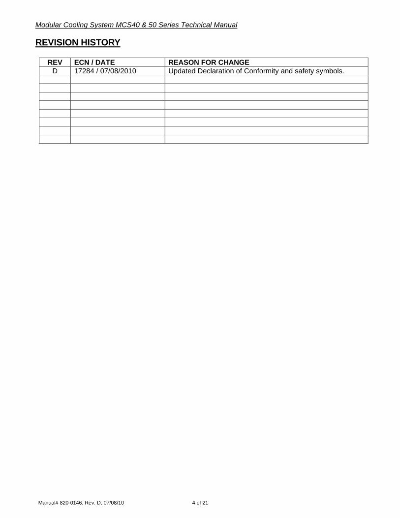
REVISION HISTORY
REV ECN / DATE REASON FOR CHANGE D 17284 / 07/08/2010 Updated Declaration of Conformity and safety symbols.
Modular Cooling System MCS40 & 50 Series Technical Manual
Manual# 820-0146, Rev. D, 07/08/10 5 of 21
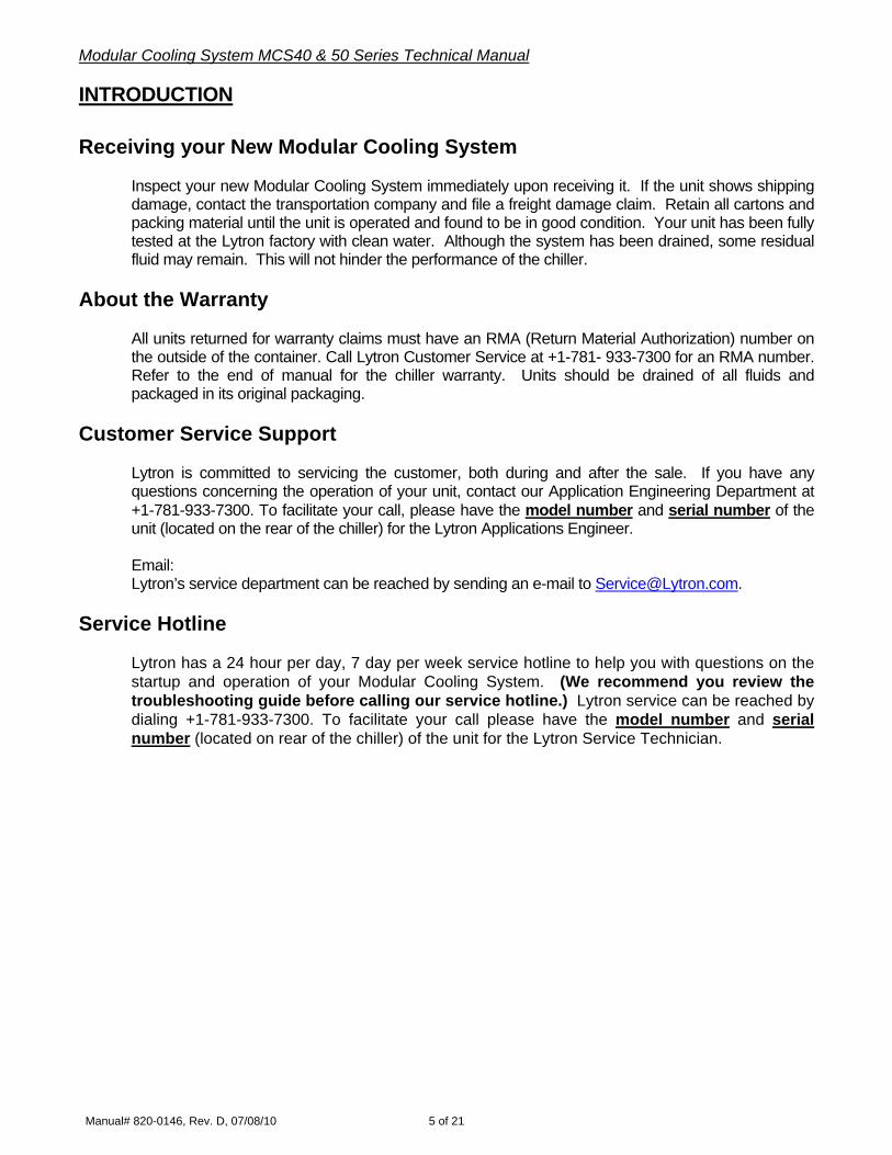
INTRODUCTION Receiving your New Modular Cooling System
Inspect your new Modular Cooling System immediately upon receiving it. If the unit shows shipping damage, contact the transportation company and file a freight damage claim. Retain all cartons and packing material until the unit is operated and found to be in good condition. Your unit has been fully tested at the Lytron factory with clean water. Although the system has been drained, some residual fluid may remain. This will not hinder the performance of the chiller.
About the Warranty
All units returned for warranty claims must have an RMA (Return Material Authorization) number on the outside of the container. Call Lytron Customer Service at +1-781- 933-7300 for an RMA number. Refer to the end of manual for the chiller warranty. Units should be drained of all fluids and packaged in its original packaging.
Customer Service Support
Lytron is committed to servicing the customer, both during and after the sale. If you have any questions concerning the operation of your unit, contact our Application Engineering Department at +1-781-933-7300. To facilitate your call, please have the model number and serial number of the unit (located on the rear of the chiller) for the Lytron Applications Engineer. Email: Lytron’s service department can be reached by sending an e-mail to [email protected].
Service Hotline
Lytron has a 24 hour per day, 7 day per week service hotline to help you with questions on the startup and operation of your Modular Cooling System. (We recommend you review the troubleshooting guide before calling our service hotline.) Lytron service can be reached by dialing +1-781-933-7300. To facilitate your call please have the model number and serial number (located on rear of the chiller) of the unit for the Lytron Service Technician.

Modular Cooling System MCS40 & 50 Series Technical Manual
Manual# 820-0146, Rev. D, 07/08/10 6 of 21
SAFETY PRECAUTIONS
This system is designed to provide fluid cooling only as specified in this manual. If you use this system in a manner other than as specified, the safety protection of the system may be impaired. Warnings are posted throughout the manual. Read and follow these important instructions. Failure to observe these instructions or use the chiller other than as specified may impair safety protection, void the warranty, and can result in permanent damage to the unit, significant property damage, personal injury and/or death. Make sure you read, understand, and follow all instructions and safety precautions listed in this manual before operating your unit. If you have any questions concerning the operation of your unit or the information in this manual, please contact our Applications Engineering Department at +1-781-933-7300.
1) Do not operate the unit without fluid in the reservoir.
2) Never place the unit in a location where excessive heat, moisture, or corrosive materials are present.
3) The unit must be plugged into a properly grounded power source.
4) Do not connect the SUPPLY or RETURN fitting to your building water supply or any pressurized source.
5) Do not use or maintain the unit outdoors. These units were not designed to withstand outdoor weather conditions.
6) Performance of installation, operation, or maintenance procedures other than those described in this manual may result in a hazardous situation and may void the Lytron warranty.
7) Transport the unit with care. Sudden jolts or drops can damage the unit.
8) Observe all warning labels. Never remove warning labels.
9) Do not operate damaged or leaking equipment.
10) Always turn the unit "OFF" and disconnect the power cord from the power source before performing any service, maintenance procedures or before moving the unit.
11) Do not operate equipment with damaged power cords.
12) A qualified technician should perform service and repairs.

Modular Cooling System MCS40 & 50 Series Technical Manual
Manual# 820-0146, Rev. D, 07/08/10 7 of 21
MODEL NUMBER DESCRIPTION
MCS40 G02 BC 1 CXXX
Basic Model Number Electrical Configurations Pump Options MCS40 – 2,400 Watts MCS50 – 3,500 Watts
G02 = 115V~ 60 Hz 1ph J02 = 230V~ 50/60 Hz 1ph
BC = 1.8 gpm Brass, Positive Displacement Pump BE = 2.3 gpm Brass, Positive Displacement Pump DA=1/4 Hp Centrifugal Pump
NOTE: Refer to the product ID label on the on the rear of your chiller for the configuration you have purchased. The table above refers to Lytron’s standard product offering for the MCS40 & 50 Series.
Custom OptionsStandard Modification

Modular Cooling System MCS40 & 50 Series Technical Manual
Manual# 820-0146, Rev. D, 07/08/10 8 of 21
PRODUCT SPECIFICATIONS
MODEL NUMBERS MCS40 MCS50
Watts 2,400 3,500 Cooling Capacity (Using water, 25°C ITD) Btu/Hr 8,200 12,000
Width-Inches 15
Depth-Inches 15 Case Dimensions
Height-Inches 24
Inlet ½” ½” Fluid Connections (FNPT, Internal)
Outlet ½” ½”
Available Pressure Head See Performance Graph
Reservoir Capacity Gallons (liters) 1.5 (5.6) 1.5 (5.6)
Maximum Liquid Temperature 131°F (55°C)
115v 50/60Hz 1Phase 6 6 Full Load Amperage
230v 50/60Hz 1Phase 3 3
Approximate Dry Weight Stand-Alone Case 1lb. (kg) 60 (27) 65 (29)
Recommended Coolant Water Water

Modular Cooling System MCS40 & 50 Series Technical Manual
Manual# 820-0146, Rev. D, 07/08/10 9 of 21
LABELS AND SILKSCREEN MARKING
T5AL250V
ATTENTION / WARNING LABEL: This label tells maintenance and users to consult the technical manual for more information. VOLTAGE LABEL: Disconnect power warning. POWER SWITCH: The symbol on the Power Switch is used to signify the power mode of the rocker style switch on the AC main ; Power On (I), Power Off (O). RETURN TO COOLING SYSTEM: The symbol on this label is used to identify the port where heated fluid returning from the customer’s machine is connected. SUPPLY TO EQUIPMENT: The symbol on this label is used to identify the line containing cooled fluid supplied to the customer’s machine is connected. GROUND LABEL: Protective earth (ground) terminal) FUSE LABEL: This label is affixed to identify the type of fuse 2AMP/250V~ Time Lag Fuses, 5 x 20mm FUSE LABEL: This label is affixed to identify the type of fuse 5AMP/250V~ Time Lag Fuses, 5 x 20mm FUSE LABEL: This label is affixed to identify the type of fuse 6.3AMP/250V~ Time Lag Fuses, 5 x 20mm

Modular Cooling System MCS40 & 50 Series Technical Manual
Manual# 820-0146, Rev. D, 07/08/10 10 of 21
ACCESS PANELRESERVOIR
FILTER CARTRIDGE HAS BEEN INSTALLED
LOW LEVEL
LOW FLOW
Label indicates the location of the reservoir access panel. Label indicates that the Filter Cartridge is installed. Label indicates when coolant level is low. Label indicates the flow of the coolant is low. ETL LABEL: Certifies that conformity to the UL standard 61010A-1 and is certified to CAN/CSA STDC22.2 No. 1010.1 CE LABEL: The symbol on this label identifies that the equipment has been certified to regulations of the European Community. WEEE LABEL: The crossed out wheeled bin label requires that the product be disposed of or recycled with the requirements of local law. PRODUCT ID LABEL: This Identification label is affixed on the backside of unit to identify the model number, Serial No., Volts, Hz, and Phase and Amps.

Modular Cooling System MCS40 & 50 Series Technical Manual
Manual# 820-0146, Rev. D, 07/08/10 11 of 21
PERFORMANCE GRAPHS

Modular Cooling System MCS40 & 50 Series Technical Manual
Manual# 820-0146, Rev. D, 07/08/10 12 of 21
GENERAL INFORMATION
Cooling System Description The MCS 40/50 is a water-to-air type liquid cooling system designed for use with laboratory equipment. The MCS 40/50 pumps ambient temperature water from the reservoir tank to the heat source being cooled, though a radiator where it is cooled, and then the fluid returns to the tank. The external plumbing and the heat source are provided buy the end user and are generally unique to the user’s process and/or location.
Lytron, Inc. MCS Modular
Heat Source
Flow (gpm)
Modular Cooling System MCS40 & 50 Series Technical Manual
Manual# 820-0146, Rev. D, 07/08/10 13 of 21
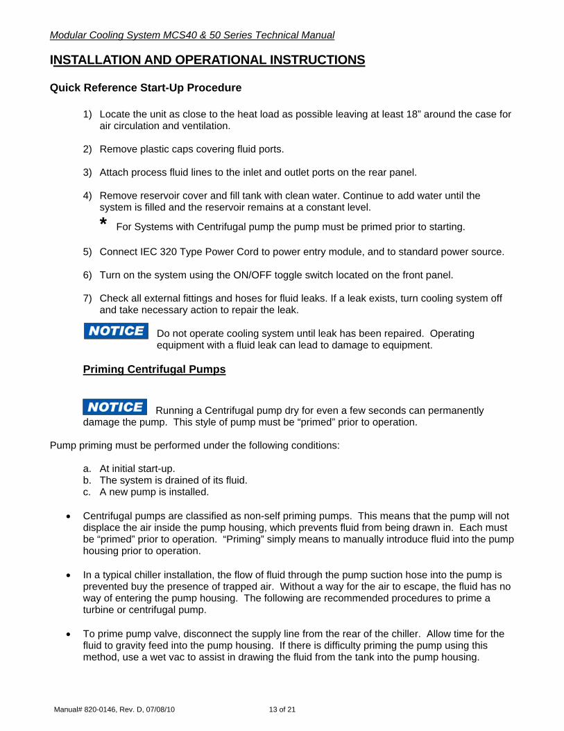
INSTALLATION AND OPERATIONAL INSTRUCTIONS
Quick Reference Start-Up Procedure 1) Locate the unit as close to the heat load as possible leaving at least 18” around the case for
air circulation and ventilation. 2) Remove plastic caps covering fluid ports. 3) Attach process fluid lines to the inlet and outlet ports on the rear panel. 4) Remove reservoir cover and fill tank with clean water. Continue to add water until the
system is filled and the reservoir remains at a constant level.
* For Systems with Centrifugal pump the pump must be primed prior to starting. 5) Connect IEC 320 Type Power Cord to power entry module, and to standard power source. 6) Turn on the system using the ON/OFF toggle switch located on the front panel. 7) Check all external fittings and hoses for fluid leaks. If a leak exists, turn cooling system off
and take necessary action to repair the leak.
Do not operate cooling system until leak has been repaired. Operating equipment with a fluid leak can lead to damage to equipment.
Priming Centrifugal Pumps
Running a Centrifugal pump dry for even a few seconds can permanently damage the pump. This style of pump must be “primed” prior to operation.
Pump priming must be performed under the following conditions:
a. At initial start-up. b. The system is drained of its fluid. c. A new pump is installed.
• Centrifugal pumps are classified as non-self priming pumps. This means that the pump will not
displace the air inside the pump housing, which prevents fluid from being drawn in. Each must be “primed” prior to operation. “Priming” simply means to manually introduce fluid into the pump housing prior to operation.
• In a typical chiller installation, the flow of fluid through the pump suction hose into the pump is
prevented buy the presence of trapped air. Without a way for the air to escape, the fluid has no way of entering the pump housing. The following are recommended procedures to prime a turbine or centrifugal pump.
• To prime pump valve, disconnect the supply line from the rear of the chiller. Allow time for the
fluid to gravity feed into the pump housing. If there is difficulty priming the pump using this method, use a wet vac to assist in drawing the fluid from the tank into the pump housing.

Modular Cooling System MCS40 & 50 Series Technical Manual
Manual# 820-0146, Rev. D, 07/08/10 14 of 21
Note: If the pump has failed to prime turn the chiller off and contact Lytron’s Service Department at
+1-781-933-7300.
Selecting Proper Location Locate the cooling system in an area with 18” minimum clearance in the rear of the unit for air circulation and ventilation. The cooling system should be located as close as possible to the heat load to minimize pressure drop due to excessive line length. Cooling lines are best run at or near the same level as the cooling system, until reaching the equipment being cooling. Plumbing to Process Fluid The process fluid connection ports are located on the rear of the system and are labeled with the
SUPPLY TOEQUIPMENT
SUPPLY and RETURN TO
COOLING SYSTEM
RETURN labels. Lines should be connected to the supply and return ports. The cooling system process fluid supply and return ports are equipped with standard 1/2” NPT fittings. When connecting fluid lines to the cooling system, use pipe sealant to ensure a leak-tight seal. Opaque lines should be used to help prevent algae growth if system is exposed to prolonged non-operating periods.
Never connect the SUPPLY or RETURN fitting to your building water supply or any pressurized source. Doing so could result in damage to the equipment.
Flexible tubing, if used, should be of heavy wall or reinforced construction. All tubing should be rated to withstand 80 psig at +30°C. Make sure all tubing connections are securely clamped. Avoid running tubing near radiators, hot water pipes, etc. If substantial lengths of tubing are necessary, insulation may be required to prevent loss of cooling capacity. It is important to use the largest diameter tubing practical. Tubing should be as straight as possible, without bends and without diameter reductions. If substantial lengths of cooling lines are required, they should be pre-filled with cooling fluid before connecting them to the unit.

Modular Cooling System MCS40 & 50 Series Technical Manual
Manual# 820-0146, Rev. D, 07/08/10 15 of 21
Fluid
Lytron recommends using clean water in the cooling system. Positive displacement pumps are susceptible to damage from abrasive materials in the process fluid. Avoid using local water with high mineral content.
Allowance should be made for the internal volume of cooling lines between the cooling system and the equipment. The tank (reservoir) can be accessed from the rear by removing the reservoir cover. Fill the tank and check level after operating for a short period of time. It may be necessary to add fluid if the level has dropped substantially.
NOTE: If the fluid is exposed to sunlight, add an algaecide to the fluid to control organic growth in lines.
Fluid Level
When the fluid is low in the tank, the sitetube on the front of the unit will be near or at the minimum water level. Top off the tank until the water has reached the maximum water level. Fuses If the circuit becomes overloaded, the fuse will blow. To replace, simply remove the blown fuse from the fuse draw on the power inlet module and replace. Electrical Requirements
In order to avoid an electrical potential at the cooling system frame due to insulation failure, a proper ground connection to the system must be provided.
Failure to do so could result in damage to the equipment, personal injury, and/or death.
Refer to the Specification section and to the product ID label on the rear of the unit for the specific electrical requirements of your unit. The cooling system power module is configured with a standard international IEC320/C20 inlet. To safely operate the chiller, use an SJT cord set with an IEC 320/C19 receptacle and an inlet plug that is compatible to the local power grid and the power requirements of the cooling system.
Modular Cooling System MCS40 & 50 Series Technical Manual
Manual# 820-0146, Rev. D, 07/08/10 16 of 21
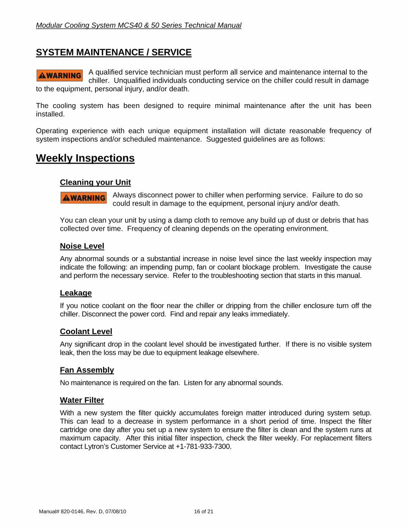
SYSTEM MAINTENANCE / SERVICE
A qualified service technician must perform all service and maintenance internal to the chiller. Unqualified individuals conducting service on the chiller could result in damage
to the equipment, personal injury, and/or death. The cooling system has been designed to require minimal maintenance after the unit has been installed. Operating experience with each unique equipment installation will dictate reasonable frequency of system inspections and/or scheduled maintenance. Suggested guidelines are as follows: Weekly Inspections
Cleaning your Unit
Always disconnect power to chiller when performing service. Failure to do so could result in damage to the equipment, personal injury and/or death.
You can clean your unit by using a damp cloth to remove any build up of dust or debris that has collected over time. Frequency of cleaning depends on the operating environment.
Noise Level Any abnormal sounds or a substantial increase in noise level since the last weekly inspection may indicate the following: an impending pump, fan or coolant blockage problem. Investigate the cause and perform the necessary service. Refer to the troubleshooting section that starts in this manual. Leakage If you notice coolant on the floor near the chiller or dripping from the chiller enclosure turn off the chiller. Disconnect the power cord. Find and repair any leaks immediately. Coolant Level Any significant drop in the coolant level should be investigated further. If there is no visible system leak, then the loss may be due to equipment leakage elsewhere. Fan Assembly No maintenance is required on the fan. Listen for any abnormal sounds. Water Filter With a new system the filter quickly accumulates foreign matter introduced during system setup. This can lead to a decrease in system performance in a short period of time. Inspect the filter cartridge one day after you set up a new system to ensure the filter is clean and the system runs at maximum capacity. After this initial filter inspection, check the filter weekly. For replacement filters contact Lytron’s Customer Service at +1-781-933-7300.
Modular Cooling System MCS40 & 50 Series Technical Manual
Manual# 820-0146, Rev. D, 07/08/10 17 of 21
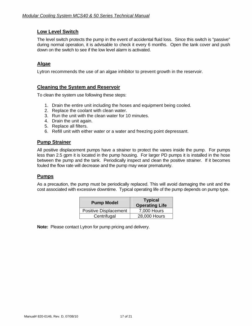
Low Level Switch The level switch protects the pump in the event of accidental fluid loss. Since this switch is "passive" during normal operation, it is advisable to check it every 6 months. Open the tank cover and push down on the switch to see if the low level alarm is activated. Algae Lytron recommends the use of an algae inhibitor to prevent growth in the reservoir. Cleaning the System and Reservoir To clean the system use following these steps:
1. Drain the entire unit including the hoses and equipment being cooled. 2. Replace the coolant with clean water. 3. Run the unit with the clean water for 10 minutes. 4. Drain the unit again. 5. Replace all filters. 6. Refill unit with either water or a water and freezing point depressant.
Pump Strainer All positive displacement pumps have a strainer to protect the vanes inside the pump. For pumps less than 2.5 gpm it is located in the pump housing. For larger PD pumps it is installed in the hose between the pump and the tank. Periodically inspect and clean the positive strainer. If it becomes fouled the flow rate will decrease and the pump may wear prematurely. Pumps As a precaution, the pump must be periodically replaced. This will avoid damaging the unit and the cost associated with excessive downtime. Typical operating life of the pump depends on pump type.
Pump Model Typical Operating Life
Positive Displacement 7,000 Hours Centrifugal 28,000 Hours
Note: Please contact Lytron for pump pricing and delivery.

Modular Cooling System MCS40 & 50 Series Technical Manual
Manual# 820-0146, Rev. D, 07/08/10 18 of 21
TROUBLE SHOOTING GUIDE
Problem Recommend Remedy
Unit will not start
Check the line cord; make sure it is plugged in. Check the voltage on the power source. Make sure it is within the rated voltage of the unit + 10%. Check that the Power Switch is on and that the fuses have not blown.
Unit will not circulate fluid
Check the reservoir level. Fill, if necessary.
Check filter and strainer for blockage.
Service Assistance
If, after following these trouble shooting steps, your unit fails to operate properly, contact Lytron for assistance or refer to website www.Lytron.com/service
Modular Cooling System MCS40 & 50 Series Technical Manual
Manual# 820-0146, Rev. D, 07/08/10 19 of 21
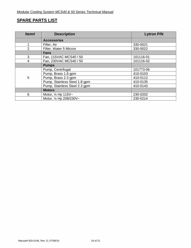
SPARE PARTS LIST
Item# Description Lytron P/N
Accessories 1 Filter, Air 330-0021 2 Filter, Water 5 Micron 330-0022 Fans
3 Fan, 115VAC MCS40 / 50 101116-01 4 Fan, 230VAC MCS40 / 50 101116-02 Pumps
Pump, Centrifugal 101773-06 Pump, Brass 1.8 gpm 410-0103 Pump, Brass 2.3 gpm 410-0112 Pump, Stainless Steel 1.8 gpm 410-0135
5
Pump, Stainless Steel 2.3 gpm 410-0143 Motors
6 Motor, ¼ Hp 115V~ 230-0202 Motor, ¼ Hp 208/230V~ 230-0214

Modular Cooling System MCS40 & 50 Series Technical Manual
Manual# 820-0146, Rev. D, 07/08/10 20 of 21
WARRANTY
Lytron agrees that the apparatus manufactured by it will be free from defects in materials and workmanship for the warranty period under normal use and service and when properly installed. The warranty period for recirculating chillers is two years from date of shipment of such apparatus to the original purchaser, maintenance items excluded, and one year from date of shipment of such apparatus to the original purchaser for all other products Lytron sells. Lytron’s obligation under this agreement is limited solely to repair or replacement, at its option, at its factories, of any part or parts thereof, returned to Lytron with transportation charges prepaid, which examination shall disclose to Lytron’s satisfaction to have been defective. THE FOREGOING EXPRESS WARRANTY IS IN LIEU OF ALL OTHER WARRANTIES, EXPRESSED OR IMPLIED, INCLUDING BUT NOT LIMITED TO WARRANTIES OF MERCHANTABILITY AND FITNESS FOR A PARTICULAR PURPOSE. LYTRON'S OBLIGATION UNDER THIS WARRANTY IS STRICTLY AND EXCLUSIVELY LIMITED TO THE REPAIR OR REPLACEMENT OF DEFECTIVE COMPONENT PARTS AND LYTRON DOES NOT ASSUME OR AUTHORIZE ANYONE TO ASSUME FOR IT ANY OTHER OBLIGATION. LYTRON ASSUMES NO RESPONSIBILITY FOR INCIDENTAL, CONSEQUENTIAL, OR OTHER DAMAGES INCLUDING, BUT NOT LIMITED TO LOSS OR DAMAGE TO PROPERTY, LOSS OF PROFITS OR REVENUE, LOSS OF THE UNIT, LOSS OF TIME, OR INCONVENIENCE. Lytron’s liability does not include any labor charges for replacement of parts, adjustments, repairs, or any other work done outside its factories and its liability does not include any resulting damage to persons, property, equipment, goods or merchandise arising out of any defect in or failure of its apparatus. Lytron’s obligation to repair or replace shall not apply to any apparatus which shall have been repaired or altered outside of its factory in any way, or which has been subject to negligence, to misuse, or to pressures in excess of stated limits. On parts not of Lytron’s manufacture, such as motors, controls, etc., Lytron extends only those warranties given to Lytron, Inc. to the extent Lytron can do so. Lytron’s agreement hereunder runs only to the immediate purchaser from Lytron, Inc. and does not extend, expressly or by implication, to any other person.

Modular Cooling System MCS40 & 50 Series Technical Manual
Manual# 820-0146, Rev. D, 07/08/10 21 of 21
DECLARATION OF CONFORMITY