LY - Farnell · PDF fileGeneral Purpose Relay LY 287 Specifications Contact Data Coil Data 1-...
16
General Purpose Relay LY 285 General Purpose Relay LY • Arc barrier equipped. • High dielectric strength (2,000 VAC). • Long dependable service life assured by Ag-Alloy contacts. • Choose models with single or bifurcated contacts, LED indicator, diode surge suppression, push-to-test button, or RC circuit. • UL, CSA, TUV, and CE approvals on all standard LY Relay Part Numbers. Ordering Information To Order: Select the part number and add the desired coil voltage rating (e.g., LY1-DC6). Note: 1. Types with specifications other than those listed are available. Contact your Omron Sales representative. 2. To order connecting sockets and mounting tracks, see “Accessories” section. 3. Relays with RC circuit are only available in AC coil voltages of 100 VAC or greater. Type Terminal Contact form Model Single contact Bifurcated contact Standard bracket mounting Upper mounting bracket Standard bracket mounting Upper mounting bracket Standard Plug-in/solder SPDT LY1 LY1F — — DPDT LY2 LY2F LY2Z LY2ZF 3PDT LY3 LY3F — — 4PDT LY4 LY4F — — PCB SPDT LY1-0 — — — DPDT LY2-0 — LY2Z-0 — 3PDT LY3-0 — — — 4PDT LY4-0 — — — LED indicator Plug-in/solder SPDT LY1N — — — DPDT LY2N — LY2ZN — 3PDT LY3N — — — 4PDT LY4N — — — Diode surge suppression SPDT LY1-D — — — DPDT LY2-D — LY2Z-D — 3PDT LY3-D — — — 4PDT LY4-D — — — LED indicator and diode surge suppression SPDT LY1N-D2 — — — DPDT LY2N-D2 — LY2ZN-D2 — 4PDT LY4N-D2 — — — RC circuit SPDT LY1-CR — — — DPDT LY2-CR — LY2Z-CR — LED indicator and RC circuit SPDT LY1N-CR — — — DPDT LY2N-CR — LY2ZN-CR —
Transcript of LY - Farnell · PDF fileGeneral Purpose Relay LY 287 Specifications Contact Data Coil Data 1-...

General Purpose Relay LY 285
General Purpose Relay
LY• Arc barrier equipped.
• High dielectric strength (2,000 VAC).• Long dependable service life assured by Ag-Alloy contacts.
• Choose models with single or bifurcated contacts, LED indicator, diode surge suppression, push-to-test button, or RC circuit.
• UL, CSA, TUV, and CE approvalson all standard LY Relay Part Numbers.
Ordering InformationTo Order: Select the part number and add the desired coil voltage rating (e.g., LY1-DC6).
Note: 1. Types with specifications other than those listed are available. Contact your Omron Sales representative.2. To order connecting sockets and mounting tracks, see “Accessories” section.3. Relays with RC circuit are only available in AC coil voltages of 100 VAC or greater.
Type Terminal Contactform
Model
Single contact Bifurcated contact
Standardbracket
mounting
Uppermountingbracket
Standardbracket
mounting
Upper mounting
bracket
Standard Plug-in/solder SPDT LY1 LY1F — —
DPDT LY2 LY2F LY2Z LY2ZF
3PDT LY3 LY3F — —
4PDT LY4 LY4F — —
PCB SPDT LY1-0 — — —
DPDT LY2-0 — LY2Z-0 —
3PDT LY3-0 — — —
4PDT LY4-0 — — —
LED indicator Plug-in/solder SPDT LY1N — — —
DPDT LY2N — LY2ZN —
3PDT LY3N — — —
4PDT LY4N — — —
Diode surgesuppression
SPDT LY1-D — — —
DPDT LY2-D — LY2Z-D —
3PDT LY3-D — — —
4PDT LY4-D — — —
LED indicatorand diode surgesuppression
SPDT LY1N-D2 — — —
DPDT LY2N-D2 — LY2ZN-D2 —
4PDT LY4N-D2 — — —
RC circuit SPDT LY1-CR — — —
DPDT LY2-CR — LY2Z-CR —
LED indicatorand RC circuit
SPDT LY1N-CR — — —
DPDT LY2N-CR — LY2ZN-CR —
286 General Purpose Relay LY
Note: 1. Types with specifications other than those listed are available. Contact your Omron Sales representative.2. To order connecting sockets and mounting tracks, see “Accessories” section.
■ Accessories
Connecting SocketsTo Order: Select the appropriate part numbers for sockets, clips, and mounting tracks (if required) from the following charts.
Track Mounted Sockets
* Track mounted socket can be used as a front connecting socket.
Back Connecting Sockets
Note: Types PYP-18, PTP-12 and PTP-10 may be cut to any desired length.
Type Terminal Contactform
Model
Single contact Bifurcated contact
Standardbracket
mounting
Uppermountingbracket
Standardbracket
mounting
Upper mounting
bracket
Push-to-testbutton
Plug-in/solder SPDT LY1l4 — — —
DPDT LY2l4 — LY2Zl2 —
3PDT LY3l4 — — —
4PDT LY4l4 — — —
LED indicator andpush-to-test button
Plug-in/solder DPDT LY2l4N — LY2Zl2N —
4PDT LY4l4N — — —
Relay Socket* Relay hold-down clip Mounting track
Standard RC circuit
SPDT PTF08A-E PYC-A1 Y92H-3 PFP-100N/PFP-50N &
DPDT PFP-M or PFP-100N2
3PDT PTF11A PFP-S (Option spacer)
4PDT PTF14A-E
Relay Solderterminalsocket
Wire wrapterminalsocket
Relay hold-down clip Socket Mounting Plate
Standard Push-to-test RC circuit Mtg. plate 1 10 12 18
SPDT PT08 PT08QN PYC-P PYC-P2 PYC-1 PYC-S PYP-1 – – PYP-18
DPDT
3PDT PT11 PT11QN PTP-1-3 – PTP-12 –
4PDT PT14 PT14QN PTP-1 PTP-10 – –
Relay PC terminal socket Relay hold-down clip
Standard Push-to-test RC circuit
SPDT PT08-0 PYC-P PYC-P2 PYC-1
DPDT
3PDT PT11-0
4PDT PT14-0

General Purpose Relay LY 287
Specifications
■ Contact Data
■ Coil Data
1- and 2-pole Types – AC
1- and 2-pole Types – DC
Note: 1. The rated current and coil resistance are measured at a coil temperature of 23°C (73°F) with tolerances of +15%, -20% for AC ratedcurrent, and ±15% for DC rated coil resistance.
2. The AC coil resistance and inductance are reference values at 60 Hz.3. The performance characteristics are measured at a coil temperature of 23°C (73°F).4. Class B coil insulation is available.
Load Single contact Bifurcated contact
SPDT DPDT, 3PDT, 4PDT DPDT
Resistive load(p.f. = 1)
Inductive load(p.f. = 0.4)
(L/R = 7 ms)
Resistive load(p.f. = 1)
Inductive load(p.f. = 0.4)
(L/R = 7 ms)
Resistive load(p.f. = 1)
Inductive load (p.f. = 0.4)
(L/R = 7 ms)
Rated load 15 A at 110 VAC 10 A at 110 VAC 10 A at 110 VAC 7.5 A at 110 VAC 5 A at 110 VAC 4 A at 110 VAC
15 A at 24 VDC 7 A at 24 VDC 10 A at 24 VDC 5 A at 24 VDC 5 A at 24 VDC 4 A at 24 VDC
Contact material Ag-Alloy
Carry current 15 A 10 A 7 A
Max. operatingvoltage
250 VAC125 VDC
Max. operatingcurrent
15 A 10 A 7 A
Max. switchingcapacity
1,700 VA 1,100 VA 1,100 VA 825 VA 550 VA 440 VA
360 W 170 W 240 W 120 W 120 W 100 W
Min. permissibleload
100 mA, 5 VDC 10 mA, 5 VDC
Ratedvoltage (V)
Rated current (mA) Coilresistance
(Ω)
Coil inductance(ref. value) (H)
Pick-upvoltage
Dropoutvoltage
Maximumvoltage
Power consumption
(VA, W)ArmatureOFF
ArmatureON
50 Hz 60 Hz (% of rated voltage)
6 214.10 183 12.20 0.04 0.08 80% max. 30% min. 110% Approx.1.00 to 1.20(60 Hz)
12 106.50 91 46 0.17 0.33
24 53.80 46 180 0.69 1.30
50 25.70 22 788 3.22 5.66
100/110 11.70/12.90 10/11 3,750 14.54 24.60 Approx.0.90 to 1.10(60 Hz)
110/120 9.90/10.80 8.40/9.20 4,430 19.20 32.10
200/220 6.20/6.80 5.30/5.80 12,950 54.75 94.07
220/240 4.80/5.30 4.20/4.60 18,790 83.50 136.40
Ratedvoltage (V)
Rated current (mA) Coilresistance
(Ω)
Coil inductance(ref. value) (H)
Pick-upvoltage
Dropoutvoltage
Maximumvoltage
Powerconsumption
(VA, W)ArmatureOFF
ArmatureON
(% of rated voltage)
6 150 40 0.16 0.33 80% max. 10% min. 110% Approx.0.9012 75 160 0.73 1.37
24 36.90 650 3.20 5.72
48 18.50 2,600 10.60 21
100/110 9.10/10 11,000 45.60 86.20
288 General Purpose Relay LY
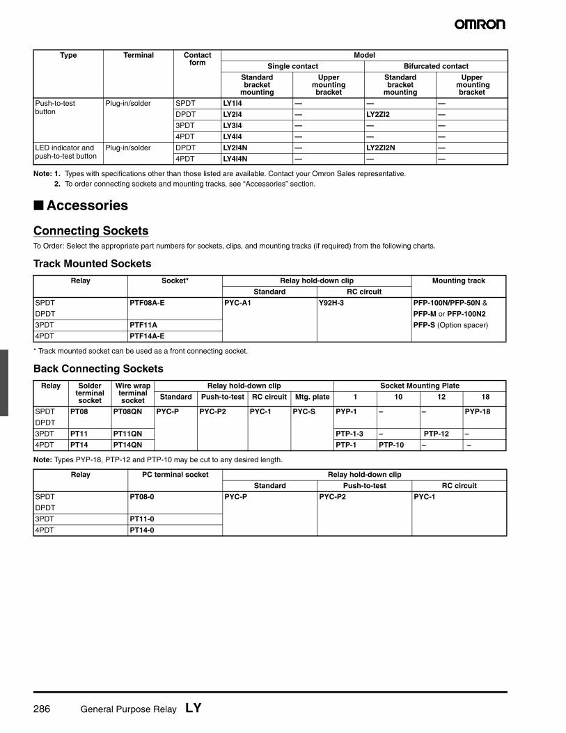
3-pole Type – AC
3-pole Type – DC
4-pole Type – AC
4-pole Type – DC
Note: 1. The rated current and coil resistance are measured at a coil temperature of 23°C (73°F) with tolerances of +15%, -20% for AC ratedcurrent, and ±15% for DC rated coil resistance.
2. The AC coil resistance and inductance are reference values at 60 Hz.3. The performance characteristics are measured at a coil temperature of 23°C (73°F).4. Class B coil insulation is available.
Ratedvoltage (V)
Rated current (mA) Coil resistance
(Ω)
Coil inductance (ref. value) (H)
Pick-up voltage
Dropout voltage
Maximum voltage
Power consumption
(VA, W)
50 Hz 60 Hz Armature OFF
Armature ON
(% of rated voltage)
6 310 270 6.70 0.03 0.05 80% max. 30% min. 110% Approx.1.60 to 2.00(60 Hz)
12 159 134 24 0.12 0.21
24 80 67 100 0.44 0.79
50 38 33 410 2.24 3.87
100/110 15.90/18.30 13.60/15.60 2,300 10.50 18.50
120 17.30 14.8 2,450 11.50 20.60
200/220 10.50/11.60 9.00/9.90 8,650 34.80 59.50
240 9.40 8 10,400 38.60 74.60
Rated voltage
(V)
Rated current (mA) Coilresistance
(Ω)
Coil inductance(ref. value) (H)
Pick-up voltage
Dropout voltage
Maximum voltage
Powerconsumption
(VA, W)Armature OFF
Armature ON
(% of rated voltage)
6 234 25.70 0.11 0.21 80% max. 10% min. 110% Approx.1.4012 112 107 0.45 0.98
24 58.60 410 1.89 3.87
48 28.20 1,700 8.53 13.90
100/110 12.70/13 8,500 29.60 54.30
Ratedvoltage (V)
Rated current (mA) Coilresistance
(Ω)
Coil inductance(ref. value) (H)
Pick-upvoltage
Dropoutvoltage
Maximumvoltage
Powerconsumption
(VA, W)ArmatureOFF
ArmatureON
50 Hz 60 Hz (% of rated voltage)
6 386 330 5 0.02 0.04 80% max. 30% min. 110% Approx.1.95 to 2.50(60 Hz)
12 199 170 20 0.10 0.17
24 93.60 80 78 0.38 0.67
50 46.80 40 350 1.74 2.88
100/110 22.50/25.50 19/21.80 1,800 10.50 17.30
120 19.00 16.40 2,200 9.30 19
200/220 11.50/13.10 9.80/11.20 6,700 33.10 57.90
240 11.00 9.50 9,000 33.20 63.40
Ratedvoltage (V)
Rated current (mA) Coilresistance
(Ω)
Coil inductance(ref. value) (H)
Pick-upvoltage
Dropoutvoltage
Maximumvoltage
Power consumption
(VA, W)ArmatureOFF
ArmatureON
(% of rated voltage)
6 240 25 0.09 0.21 80% max. 10% min. 110% Approx.1.5012 120 100 0.39 0.84
24 69 350 1.41 2.91
48 30 1,600 6.39 13.60
100/110 15/15.90 6,900 32 63.70
General Purpose Relay LY 289
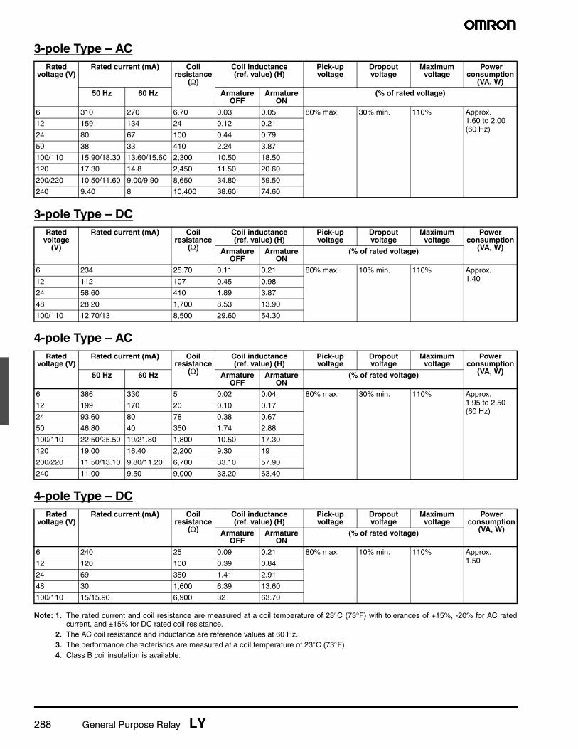
■ Characteristics
Note: Data shown are of initial value.
■ Characteristic DataMaximum switching capacity
Electrical service life
Contact resistance 50 mΩ max.
Operate time 25 ms max.
Release time 25 ms max.
Operating frequency Mechanically 18,000 operations/hour
Under rated load 1,800 operations/hour
Insulation resistance 100 MΩ min. (at 500 VDC)
Dielectric strength 2,000 VAC, 50/60 Hz for 1 minute
1,000 VAC, 50/60 Hz for 1 minute between contacts of same polarity
Vibration Mechanical durability 10 to 55 Hz, 1.00 mm (0.04 in) double amplitude
Malfunction durability 10 to 55 Hz, 1.00 mm (0.04 in) double amplitude
Shock Mechanical durability 1,000 m/s2 (approx. 100 G)
Malfunction durability 200 m/s2 (approx. 20 G)
Ambient temperature Operating LY1, LY2, LY3: -25° to 55°C; LY4 =-25° to 40°CHumidity 35 to 85% RH
Service Life Mechanically AC: 50 million operations min. (at operating frequency of 18,000 operations/hour)
DC: 100 million operations min. (at operating frequency of 18,000 operations/hour)
Electrically See “Characteristic Data”
Weight SPDT, DPDT: Approx. 40 g (1.41 oz), 3PDT: Approx. 50 g (1.76 oz)4PDT: Approx. 70 g (2.47 oz)
LY1 LY2 LY3, LY4 LY2Z
Rated operating voltage (V)
Rat
ed o
pera
ting
curr
ent (
A)
Rated operating voltage (V)
Rat
ed o
pera
ting
curr
ent (
A)
Rated operating voltage (V)
Rat
ed o
pera
ting
curr
ent (
A)
Rated operating voltage (V)
Rat
ed o
pera
ting
curr
ent (
A)
LY1 LY2 LY3, LY4 LY2Z
Switching current (A)
Ser
vice
Life
(X
106
oper
atio
ns)
Switching current (A)
Ser
vice
Life
(X
106
oper
atio
ns)
Switching current (A)
Ser
vice
Life
(X
106
oper
atio
ns)
Switching current (A)
Ser
vice
Life
(X
106
oper
atio
ns)

290 General Purpose Relay LY
DimensionsUnit: mm (inch)
■ Relays
Note: The above drawing shows LY1F. With LY2F, dimension “*”should read as eight 3.05 mm (0.12 in) dia. holes.
LY1 LY2Terminal arrangement(Bottom view)
Terminal arrangement(Bottom view)
LY3 LY4Terminal arrangement(Bottom view)
Terminal arrangement(Bottom view)
LY1-0, LY2-0, LY3-0, LY4-0 Mounting holes for LY1-0, LY2-0, LY3-0, LY4-0(Bottom view)
Note: The above drawing shows LY2-0. With LY1-0,dimension “*” should read as eight 6.35 (.25).
SPTD DPDT 3PDT 4PDT
LY1F, LY2F LY3FMountingholes
Mountingholes

General Purpose Relay LY 291
LY4F Mounting holes
LY1S, LY2S Round hole Rectangular hole
Note: The above drawing shows LY2S-US. With LY1S-US, dimension “*”should read as eight 2.03 mm (0.08 in) dia. holes.
LY3S Round hole Rectangular hole
LY4S Round hole Rectangular hole

292 General Purpose Relay LY
■ AccessoriesUnit: mm (inch)
Track mounted sockets (UL File No. E87929) (CSA Report No. LR31928)
Track mounting sockets (UL File No. E87929) (CSA Report No. LR31928)
Note: 1. UL/CSA does not apply to wire wrap (Q) type sockets.2. Values in brackets for LY❏CR.3. PTF08A-E and PTF14A-E = touch safe screws. Height = 33 mm max.
Back connecting socket (UL File No. E87929) (CSA Report No. LR31928)
PTF08A(see note 3)
Terminal arrangement/mounting holes(Top view)
PTF11A Terminal arrangement/mounting holes(Top view)
PTF14A(see note 3)
Terminal arrangement/mounting holes(Top view)
Mounting height ofrelay with socket(Applies to all PTF❏A sockets)
PT08 Terminal arrangement/(Bottom view)
PT11 Terminal arrangement/(Bottom view)

General Purpose Relay LY 293
Back connecting socket (UL File No. E87929) (CSA Report No. LR31928)
Note: Values in brackets for LY❏CR.
Back connecting socket (UL File No. E87929) (CSA Report No. LR31928)
Back connecting socket (UL File No. E87929) (CSA Report No. LR31928)
Back connecting socket (UL File No. E87929) (CSA Report No. LR31928)
PT14 Terminal arrangement(Bottom view)
Mounting height of relay with socket(Applies to all PT sockets)
PT
PT08QNPanel cut-out and terminal arrangement are the same as Type PT08.
PT11QNPanel cut-out and terminal arrangement are the same as Type PT11.
PT14QNPanel cut-out and terminal arrangement are the same as Type PT14.
PT08-0Terminal arrangement is the same as Type PT08.
Mounting holes(Bottom view)
PT11-0Terminal arrangement is the same as Type PT11.
Mounting holes(Bottom view)
PT14-0Terminal arrangement is the same as Type PT14.
Mounting holes(Bottom view)

294 General Purpose Relay LY
Unit: mm (inch)
Relay hold-down clips
Relay hold-down clips
Mounting track/end plate/spacer
*This dimension is 14.99 mm (0.59 in) on both ends in the case of PFP-100N, but on one end in the case of PFP-50N.** L = LengthPFP-50N L = 497.84 mm (19.60 in)PFP-100N L = 990.60 mm (39.00 in)PFP-100N2 L = 990.60 mm (39.00 in)***A total of twelve 24.89 x 4.57 mm (0.98 x 0.18 in) elliptic holes are provided, with six holes cut from each end of the track at a pitch of 9.91 (0.39) between holes.
PYC-A1For PTF❏A socket
PYC-SFor relay mounting plates(Applicable to Type PYP-1 and PYP-18socket mounting plates only.)
PYC-PFor PT❏ socket
PYC-P2For push-to-test button type withPT❏ socket
Y92H-3For RC circuit type
PYC-1For RC circuit type
4.5
15 25 25 25 25 * 10 10 1000 (500)*
7.3±0.15
35±0.3 27±0.15
15 (5) 1
4.5
15 25 25 25 25 15 10 10 1000±4
35±0.3 27 24
16
29.2
1 1.5
* The figure in parenthesis is for PFP-50N.
PFP-100N, PFP-50N (Conforming to EN 50022)
PFP-100N2 (Conforming to EN 50022)

General Purpose Relay LY 295
PFP-M end plate PFP-S spacer
Socket mounting plates [t=1.52 (.06)] Number of socket specs.
Socket needed 1 10 12 18
PT08, PT08QN PYP-1 – – PYP-18
PT11, PT11QN PTP-1-3 – PTP-1-2 _
PT14, PT14QN PTP-1 PTP-10 – –
PTP-10 PTP-12
PYP-1 PTP-1-3 PTP-1 PYP-18
PTP-10 PTP-12
296 General Purpose Relay LY
■ Relay Options
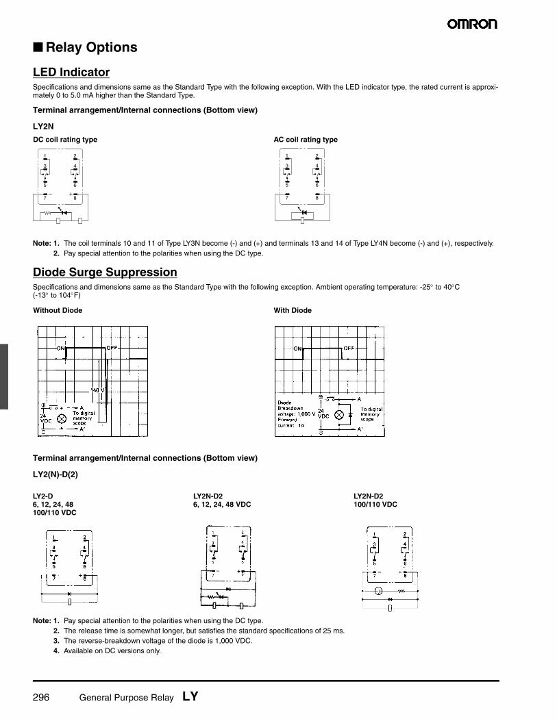
LED IndicatorSpecifications and dimensions same as the Standard Type with the following exception. With the LED indicator type, the rated current is approxi-mately 0 to 5.0 mA higher than the Standard Type.
Terminal arrangement/Internal connections (Bottom view)
LY2N
Note: 1. The coil terminals 10 and 11 of Type LY3N become (-) and (+) and terminals 13 and 14 of Type LY4N become (-) and (+), respectively.2. Pay special attention to the polarities when using the DC type.
Diode Surge SuppressionSpecifications and dimensions same as the Standard Type with the following exception. Ambient operating temperature: -25° to 40°C (-13° to 104°F)
Terminal arrangement/Internal connections (Bottom view)
LY2(N)-D(2)
Note: 1. Pay special attention to the polarities when using the DC type.2. The release time is somewhat longer, but satisfies the standard specifications of 25 ms.3. The reverse-breakdown voltage of the diode is 1,000 VDC.4. Available on DC versions only.
1
3
5
7
2
4
6
8
DC coil rating type AC coil rating type
1
3
5
7
2
4
6
8
Without Diode With Diode
LY2-D6, 12, 24, 48100/110 VDC
LY2N-D26, 12, 24, 48 VDC
LY2N-D2100/110 VDC
General Purpose Relay LY 297
■ Relay Options
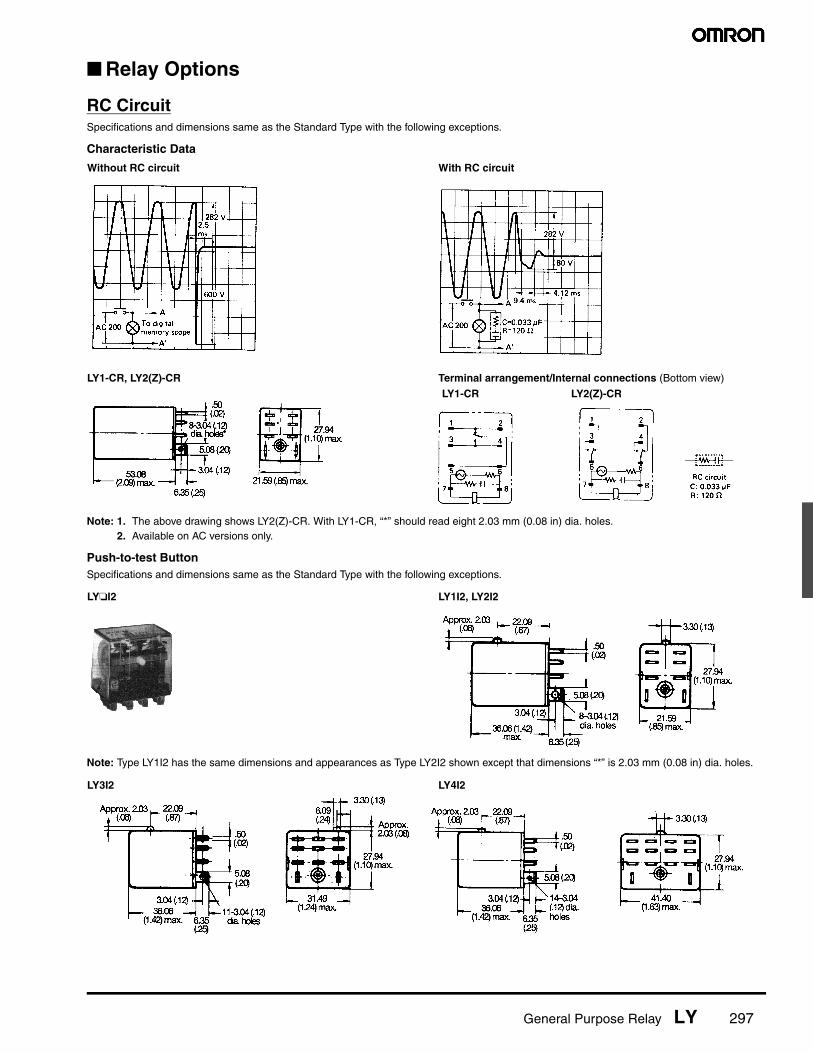
RC CircuitSpecifications and dimensions same as the Standard Type with the following exceptions.
Characteristic Data
Note: 1. The above drawing shows LY2(Z)-CR. With LY1-CR, “*” should read eight 2.03 mm (0.08 in) dia. holes.2. Available on AC versions only.
Push-to-test ButtonSpecifications and dimensions same as the Standard Type with the following exceptions.
Note: Type LY1I2 has the same dimensions and appearances as Type LY2I2 shown except that dimensions “*” is 2.03 mm (0.08 in) dia. holes.
Without RC circuit With RC circuit
LY1-CR, LY2(Z)-CR Terminal arrangement/Internal connections (Bottom view)
LY1-CR LY2(Z)-CR
LY❏I2 LY1I2, LY2I2
LY3I2 LY4I2

298 General Purpose Relay LY
■ ApprovalsUL Recognized Type (File No. E41643)
CSA Certified Type (File No. LR31928)
VDE Approved Type (File No. 9903 [SPDT, DPDT & 3PDT], File No. 9947 [4PDT])
LR (Lloyd's Register) Approved Type (File No. 562KOB-204523)
SEV Listed Type (File No. D7 91/82 [2- & 4-pole], D 91/204a [1- & 3-pole])
Note: 1. The rated values approved by each of the safety standards (e.g., UL, CSA, VDE, and SEV) may be different from the performance char-acteristics individually defined in this catalog.
2. In the interest of product improvement, specifications are subject to change.
Type Contact form Coil ratings Contact ratings Number of test operations
LY1❏ SPDT 6 to 240 VAC 15A, 30VDC (Resistive), 40°C 6 x 10³
6 to 120 VDC 15A, 240VAC (General use), 40°CTV-5, 120VAC, 40°C 25 x 103
1/2HP, 120VAC, 50°CLY2❏ DPDT 15A, 28VDC (Resistive), 40°C 6 x 10³
15A, 120VAC (Resistive), 40°C12A, 240VAC (General use), 40°C1/2HP, 120VAC, 50°C 25 x 103
TV-3, 120VAC, 40°CLY3❏LY4❏
3PDT 10A, 30VDC (Resistive), 40°C (Same polarity ) 6 x 10³
4PDT 10A, 240VAC (General use), 40°C (Same polarity )
1/2HP, 240VAC, 40°CLY2Z❏(Bifurcated)
DPDT 7A, 240VAC (General use), 40°C 6 x 10³
7A, 28VDC (Resistive), 40°C
Type Contact form Coil ratings Contact ratings
LY1❏ SPDT 6 to 240 VAC 15 A, 120 VAC (Inductive)
6 to 120 VDC 10 A, 240 VAC (Inductive)
15 A, 28 VDC (Resistive)
TV-5 (ACTV)
LY2❏ DPDT 13 A, 28 VDC (Resistive)
12 A, 120 VAC (Inductive)
10 A, 240 VAC (Inductive)
1/3 HP, 120 VAC (Motor)
TV-3 (ACTV)
LY3❏
LY3❏
3PDT 10 A, 240 VAC (Inductive)
4PDT 10 A, 28 VDC (Resistive)
Type Contact form Coil ratings Contact ratings
LY❏-VD SPDT 6, 12, 24, 50, 10 A, 220 VAC (Resistive)
110, 220 VAC 10 A, 28 VDC (Resistive)
and 6, 12, 24, 7 A, 220 VAC (Inductive)
48, 110 VDC 7 A, 28 VDC (Inductive)
LY❏-VD DPDT 7 A, 220 VAC (Resistive)
3PDT 7 A, 28 VDC (Resistive)
4PDT 4 A, 28 VDC and 4A, 220 VAC (Inductive)
Type Contact form Coil ratings Contact ratings
LY❏ DPDT 6 to 240 VAC 7.5 A, 230 VAC (Inductive)
4PDT 6 to 110 VDC 5 A, 24 VDC (Inductive)
Type Contact form Coil ratings Contact ratings
LY❏-SV SPDT 6 to 240 VAC 15 A, 220 VAC (Resistive)
6 to 110 VDC 15 A, 24 VDC (Resistive)
LY❏-SV DPDT 10 A, 220 VAC (Resistive)
3PDT 10 A, 24 VDC (Resistive)
4PDT
14
Read and Understand This CatalogPlease read and understand this catalog before purchasing the products. Please consult your OMRON representative if you have any questions orcomments.
Warranty and Limitations of Liability
WARRANTYOMRON's exclusive warranty is that the products are free from defects in materials and workmanship for a period of one year (or other period if specified)from date of sale by OMRON.
OMRON MAKES NO WARRANTY OR REPRESENTATION, EXPRESS OR IMPLIED, REGARDING NON-INFRINGEMENT, MERCHANTABILITY, ORFITNESS FOR PARTICULAR PURPOSE OF THE PRODUCTS. ANY BUYER OR USER ACKNOWLEDGES THAT THE BUYER OR USER ALONE HASDETERMINED THAT THE PRODUCTS WILL SUITABLY MEET THE REQUIREMENTS OF THEIR INTENDED USE. OMRON DISCLAIMS ALL OTHERWARRANTIES, EXPRESS OR IMPLIED.
LIMITATIONS OF LIABILITYOMRON SHALL NOT BE RESPONSIBLE FOR SPECIAL, INDIRECT, OR CONSEQUENTIAL DAMAGES, LOSS OF PROFITS OR COMMERCIAL LOSSIN ANY WAY CONNECTED WITH THE PRODUCTS, WHETHER SUCH CLAIM IS BASED ON CONTRACT, WARRANTY, NEGLIGENCE, OR STRICTLIABILITY.
In no event shall the responsibility of OMRON for any act exceed the individual price of the product on which liability is asserted.
IN NO EVENT SHALL OMRON BE RESPONSIBLE FOR WARRANTY, REPAIR, OR OTHER CLAIMS REGARDING THE PRODUCTS UNLESSOMRON'S ANALYSIS CONFIRMS THAT THE PRODUCTS WERE PROPERLY HANDLED, STORED, INSTALLED, AND MAINTAINED AND NOTSUBJECT TO CONTAMINATION, ABUSE, MISUSE, OR INAPPROPRIATE MODIFICATION OR REPAIR.
Application Considerations
SUITABILITY FOR USEOMRON shall not be responsible for conformity with any standards, codes, or regulations that apply to the combination of products in the customer'sapplication or use of the products.
At the customer's request, OMRON will provide applicable third party certification documents identifying ratings and limitations of use that apply to theproducts. This information by itself is not sufficient for a complete determination of the suitability of the products in combination with the end product,machine, system, or other application or use.
The following are some examples of applications for which particular attention must be given. This is not intended to be an exhaustive list of all possibleuses of the products, nor is it intended to imply that the uses listed may be suitable for the products:
• Outdoor use, uses involving potential chemical contamination or electrical interference, or conditions or uses not described in this catalog.
• Nuclear energy control systems, combustion systems, railroad systems, aviation systems, medical equipment, amusement machines, vehicles,safety equipment, and installations subject to separate industry or government regulations.
• Systems, machines, and equipment that could present a risk to life or property.
Please know and observe all prohibitions of use applicable to the products.
NEVER USE THE PRODUCTS FOR AN APPLICATION INVOLVING SERIOUS RISK TO LIFE OR PROPERTY WITHOUT ENSURING THAT THESYSTEM AS A WHOLE HAS BEEN DESIGNED TO ADDRESS THE RISKS, AND THAT THE OMRON PRODUCTS ARE PROPERLY RATED ANDINSTALLED FOR THE INTENDED USE WITHIN THE OVERALL EQUIPMENT OR SYSTEM.
PROGRAMMABLE PRODUCTSOMRON shall not be responsible for the user's programming of a programmable product, or any consequence thereof.
Disclaimers
CHANGE IN SPECIFICATIONSProduct specifications and accessories may be changed at any time based on improvements and other reasons.
It is our practice to change model numbers when published ratings or features are changed, or when significant construction changes are made.However, some specifications of the products may be changed without any notice. When in doubt, special model numbers may be assigned to fix orestablish key specifications for your application on your request. Please consult with your OMRON representative at any time to confirm actualspecifications of purchased products.
DIMENSIONS AND WEIGHTSDimensions and weights are nominal and are not to be used for manufacturing purposes, even when tolerances are shown.
PERFORMANCE DATAPerformance data given in this catalog is provided as a guide for the user in determining suitability and does not constitute a warranty. It may represent theresult of OMRON’s test conditions, and the users must correlate it to actual application requirements. Actual performance is subject to the OMRONWarranty and Limitations of Liability.
ERRORS AND OMISSIONSThe information in this document has been carefully checked and is believed to be accurate; however, no responsibility is assumed for clerical,typographical, or proofreading errors, or omissions.
2010.1In the interest of product improvement, specifications are subject to change without notice.
OMRON CorporationIndustrial Automation Companyhttp://www.ia.omron.com/
(c)Copyright OMRON Corporation 2010 All Right Reserved.
ALL DIMENSIONS SHOWN ARE IN MILLIMETERS.
To convert millimeters into inches, multiply by 0.03937. To convert grams into ounces, multiply by 0.03527.

J002-E1-10 06/09 Note: Specifications are subject to change. © 2010 Omron Electronics LLC
OMRON CANADA, INC. • HEAD OFFICEToronto, ON, Canada • 416.286.6465 • 866.986.6766www.omron247.com
OMRON ELETRÔNICA DO BRASIL LTDA • HEAD OFFICESão Paulo, SP, Brasil • 55.11.2101.6300 • www.omron.com.br
OMRON ELECTRONICS MEXICO SA DE CV • HEAD OFFICEApodaca, N.L. • 52.811.156.99.10 • 001.800.556.6766 • [email protected]
OMRON ARGENTINA • SALES OFFICECono Sur • 54.11.4783.5300
OMRON CHILE • SALES OFFICESantiago • 56.9.9917.3920
OTHER OMRON LATIN AMERICA SALES54.11.4783.5300
OMRON ELECTRONICS LLC • THE AMERICAS HEADQUARTERS • Schaumburg, IL USA • 847.843.7900 • 800.556.6766 • www.omron247.com
OMRON EUROpE B.V. Wegalaan 67-69, NL-2132 JD, Hoofddorp, The Netherlands. Tel: +31 (0) 23 568 13 00 Fax: +31 (0) 23 568 13 88 www.industrial.omron.eu


![FTR-LY Series [695KB] - · PDF fileFTR-LY Series POWER RELAY 1 POLE - 6A Slim Type (Medium Load Control) n PARTNUMBER INFORMATION FTR-LY A A 005 Y - SK [Example] (a) (b](https://static.fdocuments.us/doc/165x107/5a7bb4977f8b9a72118c2178/ftr-ly-series-695kb-series-power-relay-1-pole-6a-slim-type-medium-load-control.jpg)