LX-Series Commands Reference Guidesup.xenya.si/sup/info/mrv/FiberDrivers/MRV_LXsseries/LX... ·...
1114
LX-Series Commands Reference Guide 451-0310P Corporate Headquarters MRV Communications, Inc. Corporate Center 20415 Nordhoff Street Chatsworth, CA 91311 Tel: 818-773-0900 Fax: 818-773-0906 www.mrv.com (Internet) MRV Americas Service and Support 295 Foster Street Littleton, MA 01460 Tel: 800-435-7997 Tel: +001 978-952-4888 (Outside U.S.) Email: [email protected] MRV America Sales 295 Foster Street Littleton, MA 01460 Tel: 800-338-5316 (U.S.) Email: [email protected] MRV International Sales Business Park Moerfelden Waldeckerstrasse 13 64546 Moerfelden-Walldorf Germany Tel: (49) 6105/2070 Fax: (49) 6105/207-100 Email: [email protected]
Transcript of LX-Series Commands Reference Guidesup.xenya.si/sup/info/mrv/FiberDrivers/MRV_LXsseries/LX... ·...
LX-Series CommandsReference Guide
451-0310P
Corporate Headquarters
MRV Communications, Inc. Corporate Center20415 Nordhoff StreetChatsworth, CA 91311
Tel: 818-773-0900Fax: 818-773-0906
www.mrv.com (Internet)
MRV Americas Service and Support295 Foster StreetLittleton, MA 01460Tel: 800-435-7997Tel: +001 978-952-4888 (Outside U.S.)Email: [email protected]
MRV America Sales295 Foster StreetLittleton, MA 01460Tel: 800-338-5316 (U.S.)Email: [email protected]
MRV International SalesBusiness Park MoerfeldenWaldeckerstrasse 1364546 Moerfelden-WalldorfGermanyTel: (49) 6105/2070Fax: (49) 6105/207-100Email: [email protected]

All rights reserved. No part of this publication may be reproduced without the prior written consent of MRV Communications, Inc. The information in this document is subject to change without notice and should not be construed as a commitment by MRV Communications, Inc. MRV Communications, Inc. reserves the right to revise this publication and to make changes in content from time to time, without obligation to provide notification of such revision or changes. MRV Communications, Inc. assumes no responsibility for errors that may appear in this document.
Copyright © 2005 by MRV Communications, Inc.
This product includes software developed by the OpenSSL Project for use in the OpenSSL Toolkit (http://www.openssl.org/).
This product includes cryptographic software written by Eric Young ([email protected]).
This product includes software written by Tim Hudson ([email protected]).
Service InformationShould you experience trouble with this equipment, please contact one of the following support locations:
• If you purchased your equipment in the Americas, contact MRV Americas Service and Support in the U.S. at 978-952-4888. (If you are calling from outside the U.S., call +011 978-952-4888.)
• If you purchased your equipment outside the Americas (Europe, EU, Middle-East, Africa, Asia), contact MRV International Service and Support at 972-4-993-6200.
2 MRV Communications, Inc. www.mrv.com 451-0310P
Secure Shell DisclaimerTHE SECURE SHELL SOFTWARE IS PROVIDED BY ERIC YOUNG "AS IS" AND ANY EXPRESS OR IMPLIED WARRANTIES, INCLUDING, BUT NOT LIMITED TO, THE IMPLIED WARRANTIES OF MERCHANTABILITY AND FITNESS FOR A PARTICULAR PURPOSE ARE DISCLAIMED. IN NO EVENT SHALL THE AUTHOR OR CONTRIBUTORS BE LIABLE FOR ANY DIRECT, INDIRECT, INCIDENTAL, SPECIAL, EXEMPLARY, OR CONSEQUENTIAL DAMAGES (INCLUDING, BUT NOT LIMITED TO, PROCUREMENT OR SUBSTITUTE GOODS OR SERVICES; LOSS OF USE, DATA, OR PROFITS; OR BUSINESS INTERRUPTION) HOWEVER CAUSED AND ON ANY THEORY OF LIABILITY, WHETHER IN CONTRACT, STRICT LIABILITY, OR TORT (INCLUDING NEGLIGENCE OR OTHERWISE) ARISING IN ANY WAY OUT OF THE USE OF THIS SOFTWARE, EVEN IF ADVISED OF THE POSSIBILITY OF SUCH DAMAGE.
EXPORT NOTICE
MRV models contain 128-bit encryption software. Export of this product is restricted under U.S. law. Information is available from the U.S. Department of Commerce, Bureau of Export Administration at www.bxa.doc.gov.
451-0310P MRV Communications, Inc. www.mrv.com 3

4 MRV Communications, Inc. www.mrv.com 451-0310P

Table of Contents
Preface ................................................................................................................ 33Conventions ................................................................................................................................. 34Navigating the LX Command Line Interface (CLI) .................................................................... 35Command Mode Descriptions ..................................................................................................... 37Online Help ................................................................................................................................. 45Using the Function Keys ............................................................................................................. 46Related Documents ..................................................................................................................... 46
Chapter 1 - User Commands ............................................................................ 47clear ........................................................................................................................................ 48cluster command .................................................................................................................... 49cluster search .......................................................................................................................... 50connect escape ....................................................................................................................... 51connect port async ................................................................................................................. 52dial back ................................................................................................................................. 53dial direct ............................................................................................................................... 54dial ppp .................................................................................................................................. 55dial reverse ............................................................................................................................. 56enable ..................................................................................................................................... 57exit ......................................................................................................................................... 58menu ....................................................................................................................................... 59message user .......................................................................................................................... 60monitor/show audit log .......................................................................................................... 61monitor/show clock ................................................................................................................ 63monitor/show command log .................................................................................................. 64monitor/show configuration ................................................................................................... 65monitor/show configuration log ............................................................................................. 67monitor/show current user ..................................................................................................... 68monitor/show databuffer log .................................................................................................. 71monitor/show debug all ......................................................................................................... 73monitor/show debug flash ...................................................................................................... 74monitor/show debug interface ppp ........................................................................................ 75monitor/show debug port async ............................................................................................. 76monitor/show debug port virtual ............................................................................................ 78monitor/show debug snmp ..................................................................................................... 79monitor/show debug subscriber ............................................................................................. 80monitor/show debug system .................................................................................................. 81monitor/show debug trigger action ........................................................................................ 82
451-0310P MRV Communications, Inc. www.mrv.com 5

monitor/show device status .................................................................................................... 83monitor/show device summary .............................................................................................. 85monitor/show hdam alarm name characteristics .................................................................... 86monitor/show hdam alarm name status ................................................................................. 88monitor/show hdam analog name characteristics .................................................................. 89monitor/show hdam analog name status ................................................................................ 91monitor/show hdam characteristics ....................................................................................... 93monitor/show hdam control name characteristics ................................................................. 96monitor/show hdam control name status ............................................................................... 97monitor/show hdam mapping ................................................................................................ 98monitor/show hdam port/slot/point characteristics .............................................................. 100monitor/show hdam port/slot/point status ........................................................................... 103monitor/show hdam status ................................................................................................... 106monitor/show interface bonding characteristics .................................................................. 108monitor/show interface bonding status ................................................................................ 110monitor/show interface broadcast group characteristics ...................................................... 112monitor/show interface broadcast group summary .............................................................. 114monitor/show interface characteristics ................................................................................ 115monitor/show interface ipv6 characteristics ........................................................................ 118monitor/show interface ipv6 status ...................................................................................... 120monitor/show interface port mapping .................................................................................. 121monitor/show interface ppp characteristics ......................................................................... 123monitor/show interface ppp status ....................................................................................... 126monitor/show interface rotary .............................................................................................. 128monitor/show interface status .............................................................................................. 129monitor/show interface summary ........................................................................................ 131monitor/show ip6tables ........................................................................................................ 132monitor/show iptables .......................................................................................................... 133monitor/show ipv6 neighbor device ethx ............................................................................. 134monitor/show ipv6 routes device ethx ................................................................................. 135monitor/show ipv6 tunnel .................................................................................................... 136monitor/show kernel log ...................................................................................................... 137monitor/show ldap characteristics ....................................................................................... 138monitor/show ldap status ..................................................................................................... 140monitor/show ldap summary ............................................................................................... 141monitor/show log ................................................................................................................. 142monitor/show message ......................................................................................................... 143monitor/show notification log .............................................................................................. 144monitor/show notification message ..................................................................................... 145monitor/show notification profile service ............................................................................ 146
6 MRV Communications, Inc. www.mrv.com 451-0310P

monitor/show notification profile user ................................................................................ 147monitor/show outlet ............................................................................................................. 148monitor/show outlet group status ......................................................................................... 150monitor/show port apd ......................................................................................................... 152monitor/show port async apd ............................................................................................... 153monitor/show port async characteristics .............................................................................. 155monitor/show port async modem ......................................................................................... 159monitor/show port async status ............................................................................................ 161monitor/show port async summary ...................................................................................... 166monitor/show port async tcp characteristics ........................................................................ 167monitor/show port characteristics ........................................................................................ 169monitor/show port ethernet characteristics .......................................................................... 170monitor/show port ethernet status ........................................................................................ 171monitor/show port ethernet summary .................................................................................. 173monitor/show port modem ................................................................................................... 174monitor/show port status ...................................................................................................... 175monitor/show radius characteristics ..................................................................................... 176monitor/show radius status .................................................................................................. 178monitor/show radius summary ............................................................................................. 180monitor/show route .............................................................................................................. 182monitor/show securid characteristics ................................................................................... 183monitor/show securid status ................................................................................................. 185monitor/show securid summary ........................................................................................... 187monitor/show service ........................................................................................................... 188monitor/show session ........................................................................................................... 189monitor/show snmp characteristics ...................................................................................... 191monitor/show snmp client .................................................................................................... 192monitor/show snmp v3 access ............................................................................................. 194monitor/show snmp v3 group .............................................................................................. 196monitor/show snmp v3 misc ................................................................................................ 197monitor/show snmp v3 user ................................................................................................. 198monitor/show snmp v3 view ................................................................................................ 200monitor/show subscriber ...................................................................................................... 202monitor/show subscriber characteristics .............................................................................. 207monitor/show subscriber status ............................................................................................ 208monitor/show subscriber summary ...................................................................................... 209monitor/show subscriber tcp ................................................................................................ 210monitor/show system characteristics ................................................................................... 211monitor/show system ppciboot ............................................................................................ 215monitor/show system power ................................................................................................ 216
451-0310P MRV Communications, Inc. www.mrv.com 7
monitor/show system status ................................................................................................. 218monitor/show tacacs+ characteristics .................................................................................. 221monitor/show tacacs+ status ................................................................................................ 224monitor/show tacacs+ summary .......................................................................................... 226monitor/show trigger-action action ...................................................................................... 228monitor/show trigger-action rule characteristics ................................................................. 229monitor/show trigger-action rule status ............................................................................... 231monitor/show trigger-action rule summary ......................................................................... 233monitor/show trigger-action trigger ..................................................................................... 234monitor/show users .............................................................................................................. 237monitor/show version .......................................................................................................... 238no ......................................................................................................................................... 239outlet .................................................................................................................................... 240outlet group .......................................................................................................................... 241pause enable ......................................................................................................................... 242ping ...................................................................................................................................... 243shell ...................................................................................................................................... 244ssh ........................................................................................................................................ 245telnet ..................................................................................................................................... 246terminal ................................................................................................................................ 247
Chapter 2 - Superuser Commands ................................................................ 249clear ...................................................................................................................................... 250config rlogin enable ............................................................................................................. 251config rlogin transparent enable .......................................................................................... 252config subscriber rlogin dedicated service ........................................................................... 253configuration ........................................................................................................................ 254connect port async ............................................................................................................... 255control port async ................................................................................................................. 256debug cluster enable ............................................................................................................. 257debug flash enable ............................................................................................................... 258debug interface ppp enable .................................................................................................. 259debug port async enable ....................................................................................................... 260debug snmp enable ............................................................................................................... 261debug subscriber enable ....................................................................................................... 262debug system enable ............................................................................................................ 263debug trigger action enable .................................................................................................. 264dial back ............................................................................................................................... 265dial direct ............................................................................................................................. 266dial ppp ................................................................................................................................ 267
8 MRV Communications, Inc. www.mrv.com 451-0310P
dial reverse ........................................................................................................................... 268exit ....................................................................................................................................... 269logout ................................................................................................................................... 270menu name ........................................................................................................................... 271message user ........................................................................................................................ 272monitor/show ....................................................................................................................... 273monitor/show ntp status .......................................................................................................277no ......................................................................................................................................... 279notify .................................................................................................................................... 280outlet .................................................................................................................................... 281outlet group .......................................................................................................................... 282pause enable ......................................................................................................................... 283ping ...................................................................................................................................... 284reload ................................................................................................................................... 285restart notification ................................................................................................................ 286rlogin host ............................................................................................................................ 287rlogin transparent host ......................................................................................................... 288rlogin username host ............................................................................................................ 289rlogin username transparent host ......................................................................................... 290save configuration ................................................................................................................ 291script ..................................................................................................................................... 293send trap message ................................................................................................................ 294setup ..................................................................................................................................... 295shell ...................................................................................................................................... 296shell command ..................................................................................................................... 297ssh ........................................................................................................................................ 298telnet ..................................................................................................................................... 299terminal ................................................................................................................................ 300update ................................................................................................................................... 301zero all .................................................................................................................................. 302zero databuffer port async .................................................................................................... 303zero log ................................................................................................................................ 304zero securid secret ................................................................................................................ 305
Chapter 3 - Configuration Commands ........................................................... 307aaa ........................................................................................................................................ 308authenticate image enable .................................................................................................... 309boot configuration from flash .............................................................................................. 310boot configuration from name ............................................................................................. 311boot configuration from network ......................................................................................... 312
451-0310P MRV Communications, Inc. www.mrv.com 9

clock ..................................................................................................................................... 313cluster ................................................................................................................................... 314copy port .............................................................................................................................. 315copy subscriber .................................................................................................................... 316date ....................................................................................................................................... 317default boot .......................................................................................................................... 318default configuration ............................................................................................................ 319default log size ..................................................................................................................... 320default outlet group off time ................................................................................................ 321default ppciboot password ................................................................................................... 322default tftp ............................................................................................................................ 323domain name ........................................................................................................................ 324end ........................................................................................................................................ 325exit ....................................................................................................................................... 326fingerd enable ...................................................................................................................... 327gateway ................................................................................................................................ 328hostname .............................................................................................................................. 329interface ............................................................................................................................... 330ip6tables ............................................................................................................................... 331iptables ................................................................................................................................. 332ipv6 neighbor address .......................................................................................................... 333ipv6 route address ................................................................................................................ 334ipv6 tunnel default ttl ........................................................................................................... 335ipv6 tunnel name remote any local enable ........................................................................... 336ipv6 tunnel name remote local ipv6 address enable ............................................................ 337ipv6 tunnel ttl ....................................................................................................................... 339load configuration from network ......................................................................................... 340location ................................................................................................................................. 341log size ................................................................................................................................. 342menu ..................................................................................................................................... 343message enable .................................................................................................................... 344minimum password length ................................................................................................... 345monitor/show ....................................................................................................................... 346no ......................................................................................................................................... 350no ipv6 tunnel ...................................................................................................................... 351notification ........................................................................................................................... 352ntp enable ............................................................................................................................. 353ntp server address ................................................................................................................. 354ntp server alternate address .................................................................................................. 355ntp server alternate ipv6 address .......................................................................................... 356
10 MRV Communications, Inc. www.mrv.com 451-0310P

ntp server ipv6 address ........................................................................................................ 357outlet access enable .............................................................................................................. 358outlet group .......................................................................................................................... 359outlet group name ................................................................................................................ 361outlet group off time ............................................................................................................ 362password .............................................................................................................................. 363password enable ................................................................................................................... 364port async ............................................................................................................................. 365port ethernet ......................................................................................................................... 366ppciboot address .................................................................................................................. 367ppciboot address assignment option .................................................................................... 368ppciboot ethernet network link ............................................................................................ 370ppciboot gateway ................................................................................................................. 371ppciboot image filename ...................................................................................................... 372ppciboot image load from .................................................................................................... 373ppciboot mask ...................................................................................................................... 374ppciboot password ............................................................................................................... 375ppciboot tftp server .............................................................................................................. 376primary dns .......................................................................................................................... 377radius .................................................................................................................................... 378route address ........................................................................................................................ 379secondary dns ....................................................................................................................... 380securid .................................................................................................................................. 381service .................................................................................................................................. 382service ipv6 address ............................................................................................................. 383snmp ..................................................................................................................................... 384snmp enable ......................................................................................................................... 385ssh enable ............................................................................................................................. 386ssh v1 ................................................................................................................................... 387ssh v2 ................................................................................................................................... 388subscriber ............................................................................................................................. 389tacacs+ ................................................................................................................................. 390telnet client enable ............................................................................................................... 391telnet server enable .............................................................................................................. 392tftp ........................................................................................................................................ 393timed enable ......................................................................................................................... 394timezone ............................................................................................................................... 395trigger-action ........................................................................................................................ 396web_server enable ................................................................................................................ 397web_server fips jcemodule .................................................................................................. 398
451-0310P MRV Communications, Inc. www.mrv.com 11
web_server session timeout ................................................................................................. 399webbanner enable ................................................................................................................ 400webencrypt enable ............................................................................................................... 401web server port ..................................................................................................................... 402
Chapter 4 - Authentication, Accounting,and Authorization Commands ....................................................................... 403
end ........................................................................................................................................ 404exit ....................................................................................................................................... 405ldap local subscriber enable ................................................................................................. 406ldap local subscriber only .................................................................................................... 407ldap primary authentication server address ......................................................................... 408ldap primary authentication server base dn ......................................................................... 409ldap primary authentication server port ............................................................................... 410ldap primary authentication server retransmit ..................................................................... 411ldap primary authentication server timeout ......................................................................... 412ldap secondary authentication server address ...................................................................... 413ldap secondary authentication server base dn ...................................................................... 414ldap secondary authentication server port ........................................................................... 415ldap secondary authentication server retransmit .................................................................. 416ldap secondary authentication server timeout ...................................................................... 417monitor/show ....................................................................................................................... 418no ......................................................................................................................................... 422radius local subscriber enable .............................................................................................. 423radius local subscriber only ................................................................................................. 424radius period ........................................................................................................................ 425radius primary accounting server address ............................................................................ 426radius primary accounting server port ................................................................................. 427radius primary accounting server retransmit ....................................................................... 428radius primary accounting server secret .............................................................................. 429radius primary accounting server timeout ........................................................................... 430radius primary authentication server address ....................................................................... 431radius primary authentication server port ............................................................................ 432radius primary authentication server retransmit .................................................................. 433radius primary authentication server secret ......................................................................... 434radius primary authentication server timeout ...................................................................... 435radius secondary accounting server address ........................................................................ 436radius secondary accounting server port .............................................................................. 437radius secondary accounting server retransmit .................................................................... 438radius secondary accounting server secret ........................................................................... 439
12 MRV Communications, Inc. www.mrv.com 451-0310P

radius secondary accounting server timeout ........................................................................ 440radius secondary authentication server address ................................................................... 441radius secondary authentication server port ......................................................................... 442radius secondary authentication server retransmit ............................................................... 443radius secondary authentication server secret ...................................................................... 444radius secondary authentication server timeout ................................................................... 445securid authentication encryption ........................................................................................ 446securid authentication port ................................................................................................... 447securid authentication retransmit ......................................................................................... 448securid authentication timeout ............................................................................................. 449securid authentication version ............................................................................................. 450securid local subscriber enable ............................................................................................ 451securid local subscriber only ................................................................................................ 452securid master authentication server address ....................................................................... 453securid master authentication server name .......................................................................... 454securid primary authentication server address ..................................................................... 455securid primary authentication server name ........................................................................ 456securid slave authentication server address ......................................................................... 457securid slave authentication server name ............................................................................. 458tacacs+ local subscriber enable ............................................................................................ 459tacacs+ local subscriber only ............................................................................................... 460tacacs+ period ...................................................................................................................... 461tacacs+ primary accounting server address ......................................................................... 462tacacs+ primary accounting server port ............................................................................... 463tacacs+ primary accounting server retransmit ..................................................................... 464tacacs+ primary accounting server secret ............................................................................ 465tacacs+ primary accounting server timeout ......................................................................... 466tacacs+ primary authentication server address .................................................................... 467tacacs+ primary authentication server port .......................................................................... 468tacacs+ primary authentication server retransmit ................................................................ 469tacacs+ primary authentication server secret ....................................................................... 470tacacs+ primary authentication server timeout .................................................................... 471tacacs+ secondary accounting server address ...................................................................... 472tacacs+ secondary accounting server port ........................................................................... 473tacacs+ secondary accounting server retransmit .................................................................. 474tacacs+ secondary accounting server secret ........................................................................ 475tacacs+ secondary accounting server timeout ...................................................................... 476tacacs+ secondary authentication server address ................................................................. 477tacacs+ secondary authentication server port ...................................................................... 478tacacs+ secondary authentication server retransmit ............................................................ 479
451-0310P MRV Communications, Inc. www.mrv.com 13

tacacs+ secondary authentication server secret ................................................................... 480tacacs+ secondary authentication server timeout ................................................................ 481tacacs+ superuser password request enable ......................................................................... 482
Chapter 5 - Interface Commands ................................................................... 483address ................................................................................................................................. 484authentication fallback attempts .......................................................................................... 485authentication fallback enable ............................................................................................. 486authentication ldap enable ................................................................................................... 487authentication local enable ................................................................................................... 488authentication none .............................................................................................................. 489authentication radius enable ................................................................................................. 490authentication securid enable ............................................................................................... 491authentication tacacs+ enable .............................................................................................. 492banner ................................................................................................................................... 493banner file ............................................................................................................................ 494bind port async protocol ppp ............................................................................................... 495bonding link ......................................................................................................................... 496bonding link arp address ...................................................................................................... 497bonding link arp interval ...................................................................................................... 498broadcast .............................................................................................................................. 499broadcast group .................................................................................................................... 500broadcast group enable ........................................................................................................ 501default bind .......................................................................................................................... 502default mtu ........................................................................................................................... 503default rotary ........................................................................................................................ 504default ssh port ..................................................................................................................... 505default telnet port ................................................................................................................. 506default unnumbered ............................................................................................................. 507end ........................................................................................................................................ 508exit ....................................................................................................................................... 509ipv6 address ......................................................................................................................... 510ipv6 default maximum addresses ......................................................................................... 511ipv6 default probes ............................................................................................................... 512ipv6 maximum addresses ..................................................................................................... 513ipv6 probes ........................................................................................................................... 514ipv6 stateless autoconfiguration ........................................................................................... 515mask ..................................................................................................................................... 516monitor/show ....................................................................................................................... 517mtu ....................................................................................................................................... 521
14 MRV Communications, Inc. www.mrv.com 451-0310P
no ......................................................................................................................................... 522ppp ....................................................................................................................................... 523radius accounting enable ...................................................................................................... 524rotary enable ........................................................................................................................ 525rotary port ............................................................................................................................ 526rotary ssh port ...................................................................................................................... 528rotary tcp port ....................................................................................................................... 529rotary type ............................................................................................................................ 530serial ..................................................................................................................................... 531ssh port ................................................................................................................................. 532tacacs+ accounting enable ................................................................................................... 533telnet port ............................................................................................................................. 534unnumbered interface .......................................................................................................... 535
Chapter 6 - Asynchronous Commands ......................................................... 537access ................................................................................................................................... 538access control ....................................................................................................................... 540access power model ............................................................................................................. 541access tcp pipe ..................................................................................................................... 542apd retry ............................................................................................................................... 544apd signature ........................................................................................................................ 545apd timeout .......................................................................................................................... 546authentication enable ........................................................................................................... 547authentication fallback attempts .......................................................................................... 549authentication fallback enable ............................................................................................. 550autobaud enable ................................................................................................................... 551autobaud retry ...................................................................................................................... 552autodial enable ..................................................................................................................... 553autohangup enable ............................................................................................................... 554banner ................................................................................................................................... 555banner file ............................................................................................................................ 556bits ........................................................................................................................................ 557break enable ......................................................................................................................... 558connect command ................................................................................................................ 559databuffer display ................................................................................................................ 560databuffer size ...................................................................................................................... 561databuffer syslog enable ...................................................................................................... 562databuffer timestamp enable ................................................................................................ 563default apd ............................................................................................................................ 564default banner ...................................................................................................................... 565
451-0310P MRV Communications, Inc. www.mrv.com 15

default databuffer size .......................................................................................................... 566default port ........................................................................................................................... 567default power off time .......................................................................................................... 568default speed ........................................................................................................................ 569default tcp destination retries ............................................................................................... 570default tcp transmit .............................................................................................................. 571default tcp window size ....................................................................................................... 572end ........................................................................................................................................ 573exit ....................................................................................................................................... 574flowcontrol ........................................................................................................................... 575idlebuffer enable .................................................................................................................. 576modem ................................................................................................................................. 577modem enable ...................................................................................................................... 578monitor/show ....................................................................................................................... 579name ..................................................................................................................................... 583no ......................................................................................................................................... 584no outlet off .......................................................................................................................... 585outlet boot timer ................................................................................................................... 586outlet name ........................................................................................................................... 587outlet off enable ................................................................................................................... 588outlet wakeup enable ........................................................................................................... 589parity .................................................................................................................................... 590power boot sequence enable ................................................................................................ 591power cli enable ................................................................................................................... 592power factory default ........................................................................................................... 593power factory reset button enable ........................................................................................ 594power off time ...................................................................................................................... 595power scp admin name ........................................................................................................ 596power scp admin password .................................................................................................. 597power scp authentication enable .......................................................................................... 598prompt .................................................................................................................................. 599radius accounting enable ...................................................................................................... 600signal action ......................................................................................................................... 601signal all enable ................................................................................................................... 602signal all rule enable ............................................................................................................ 603special break enable ............................................................................................................. 604special break string .............................................................................................................. 605speed .................................................................................................................................... 606stopbits ................................................................................................................................. 607tacacs+ accounting enable ................................................................................................... 608
16 MRV Communications, Inc. www.mrv.com 451-0310P

tcp accept message ............................................................................................................... 609tcp accept verification enable .............................................................................................. 610tcp destination address ......................................................................................................... 611tcp destination port ............................................................................................................... 612tcp destination retries ........................................................................................................... 613tcp transmit buffered ............................................................................................................ 614tcp transmit immediate ......................................................................................................... 615tcp window size ................................................................................................................... 616telnet break control .............................................................................................................. 617telnet break string ................................................................................................................. 618telnet cr lf filtering enable .................................................................................................... 619telnet cr null filtering enable ................................................................................................ 620telnet negotiation enable ...................................................................................................... 621transparency enable .............................................................................................................. 622
Chapter 7 - Ethernet Commands .................................................................... 623description ............................................................................................................................ 624end ........................................................................................................................................ 625exit ....................................................................................................................................... 626monitor/show ....................................................................................................................... 627no description ....................................................................................................................... 631speed .................................................................................................................................... 632
Chapter 8 - Subscriber Commands ............................................................... 633access console enable ........................................................................................................... 634access outlet ......................................................................................................................... 635access outlet group ............................................................................................................... 636access port ............................................................................................................................ 637access ssh enable .................................................................................................................. 638access telnet enable .............................................................................................................. 639access web enable ................................................................................................................ 640audit log enable .................................................................................................................... 641backward_switch ................................................................................................................. 642change password enabled ..................................................................................................... 643command log enable ............................................................................................................ 644dedicated service .................................................................................................................. 645default access port ................................................................................................................ 646default access remote ........................................................................................................... 647default backward_switch ..................................................................................................... 648default forward_switch ........................................................................................................ 649
451-0310P MRV Communications, Inc. www.mrv.com 17

default idletime .................................................................................................................... 650default local_switch ............................................................................................................. 651default menu name ............................................................................................................... 652default security ..................................................................................................................... 653default ssh log level ............................................................................................................. 654default telnet escape ............................................................................................................. 655dialback enable .................................................................................................................... 656dialback number ................................................................................................................... 657end ........................................................................................................................................ 658exit ....................................................................................................................................... 659forward_switch .................................................................................................................... 660idletime ................................................................................................................................ 661local_switch ......................................................................................................................... 662login mode ........................................................................................................................... 663maxconnections ................................................................................................................... 664maxsessions ......................................................................................................................... 665menu enable ......................................................................................................................... 666menu name ........................................................................................................................... 667monitor/show ....................................................................................................................... 668no ......................................................................................................................................... 672password .............................................................................................................................. 673password enable ................................................................................................................... 674pause enable ......................................................................................................................... 675preferred service .................................................................................................................. 676prompt .................................................................................................................................. 677security level ........................................................................................................................ 678shell enable .......................................................................................................................... 679ssh key .................................................................................................................................. 680telnet escape ......................................................................................................................... 681telnet mode ........................................................................................................................... 682terminal ................................................................................................................................ 683web login mode .................................................................................................................... 684web menu name ................................................................................................................... 685
Chapter 9 - SNMP Commands ........................................................................ 687contact .................................................................................................................................. 688end ........................................................................................................................................ 689exit ....................................................................................................................................... 690get client ............................................................................................................................... 691get client community ........................................................................................................... 692
18 MRV Communications, Inc. www.mrv.com 451-0310P

get client mask ..................................................................................................................... 693get client version .................................................................................................................. 694location ................................................................................................................................. 695monitor/show ....................................................................................................................... 696no ......................................................................................................................................... 700set client ............................................................................................................................... 701set client community ............................................................................................................ 702set client mask ...................................................................................................................... 703set client version .................................................................................................................. 704trap client ............................................................................................................................. 705trap client community .......................................................................................................... 706trap client retransmit count .................................................................................................. 707trap client retransmit interval ............................................................................................... 708trap client udp port ............................................................................................................... 709trap client v3 user index ....................................................................................................... 710trap client version ................................................................................................................. 711v3 access name ..................................................................................................................... 712v3 access readview ............................................................................................................... 713v3 access seclevel ................................................................................................................ 714v3 access writeview ............................................................................................................. 715v3 group group ..................................................................................................................... 716v3 group user ....................................................................................................................... 717v3 user authpass ................................................................................................................... 718v3 user authproto ................................................................................................................. 719v3 user name ........................................................................................................................ 720v3 user privpass ................................................................................................................... 721v3 user privproto .................................................................................................................. 722v3 view mask ....................................................................................................................... 723v3 view name ....................................................................................................................... 724v3 view subtree .................................................................................................................... 725v3 view type ......................................................................................................................... 726
Chapter 10 - Modem Commands .................................................................... 727default initstring ................................................................................................................... 728dialout number ..................................................................................................................... 729end ........................................................................................................................................ 730exit ....................................................................................................................................... 731initstring ............................................................................................................................... 732monitor/show ....................................................................................................................... 733no ......................................................................................................................................... 737
451-0310P MRV Communications, Inc. www.mrv.com 19
pool enable ........................................................................................................................... 738retry ...................................................................................................................................... 739timeout ................................................................................................................................. 740
Chapter 11 - PPP Commands ......................................................................... 741authentication ....................................................................................................................... 742backup enable ...................................................................................................................... 743backup ping host .................................................................................................................. 744backup ping interface ........................................................................................................... 745backup ping interval ............................................................................................................. 746ccp enable ............................................................................................................................ 747default authentication ........................................................................................................... 748default ipcp .......................................................................................................................... 749default lcp compression ....................................................................................................... 750default lcp echo .................................................................................................................... 751default lcp failure limit ........................................................................................................ 752default lcp timeout ............................................................................................................... 753default outbound username .................................................................................................. 754default remote address ......................................................................................................... 755dialback enable .................................................................................................................... 756dialback secure ..................................................................................................................... 757end ........................................................................................................................................ 758exit ....................................................................................................................................... 759inactivity timeout ................................................................................................................. 760ipcp accept address enable ................................................................................................... 761ipcp compression enable ...................................................................................................... 762ipcp failure limit ................................................................................................................... 763ipcp timeout ......................................................................................................................... 764lcp compression enable ........................................................................................................ 765lcp echo failure ..................................................................................................................... 766lcp echo interval ................................................................................................................... 767lcp failure limit ..................................................................................................................... 768lcp timeout ........................................................................................................................... 769mode ..................................................................................................................................... 770monitor/show ....................................................................................................................... 772no ......................................................................................................................................... 776outbound dialback ................................................................................................................ 777outbound secret .................................................................................................................... 778outbound username .............................................................................................................. 779remote address ..................................................................................................................... 780
20 MRV Communications, Inc. www.mrv.com 451-0310P

Chapter 12 - Menu Commands ....................................................................... 781delete .................................................................................................................................... 782end ........................................................................................................................................ 783exit ....................................................................................................................................... 784import ................................................................................................................................... 785list ......................................................................................................................................... 786open ...................................................................................................................................... 787
Chapter 13 - Menu Editing Commands .......................................................... 789control key ........................................................................................................................... 790display .................................................................................................................................. 791end ........................................................................................................................................ 792entry ..................................................................................................................................... 793entry command .................................................................................................................... 794entry label ............................................................................................................................ 795entry menu ........................................................................................................................... 796exit ....................................................................................................................................... 797header ................................................................................................................................... 798list ......................................................................................................................................... 799menu ..................................................................................................................................... 800menu continue string ............................................................................................................ 801menu prompt ........................................................................................................................ 802no control key ...................................................................................................................... 803no entry ................................................................................................................................ 804no header .............................................................................................................................. 805no menu continue string ....................................................................................................... 806no menu prompt ................................................................................................................... 807open ...................................................................................................................................... 808save ...................................................................................................................................... 809
Chapter 14 - Broadcast Group Commands ................................................... 811end ........................................................................................................................................ 812exit ....................................................................................................................................... 813master port ........................................................................................................................... 814mode ..................................................................................................................................... 816monitor/show ....................................................................................................................... 817no master port ...................................................................................................................... 821no master port timestamp ..................................................................................................... 822no slave port ......................................................................................................................... 823no slave port discard ............................................................................................................ 824
451-0310P MRV Communications, Inc. www.mrv.com 21

no slave port localecho ........................................................................................................ 825slave port .............................................................................................................................. 826slave port discard ................................................................................................................. 828slave port localecho ............................................................................................................. 829
Chapter 15 - Notification Commands ............................................................ 831end ........................................................................................................................................ 832exit ....................................................................................................................................... 833message default .................................................................................................................... 834message facility .................................................................................................................... 835message priority ................................................................................................................... 837message string ...................................................................................................................... 839monitor/show ....................................................................................................................... 840no profile .............................................................................................................................. 844profile service ...................................................................................................................... 845profile user ........................................................................................................................... 846
Chapter 16 - Service Profile Commands ....................................................... 849async .................................................................................................................................... 850exit ....................................................................................................................................... 851localsyslog ........................................................................................................................... 852monitor/show ....................................................................................................................... 853remotesyslog ........................................................................................................................ 857smtp ...................................................................................................................................... 858snmp ..................................................................................................................................... 859snpp ...................................................................................................................................... 860tap ......................................................................................................................................... 861web ....................................................................................................................................... 862
Chapter 17 - Async Protocol Commands ...................................................... 863exit ....................................................................................................................................... 864monitor/show ....................................................................................................................... 865port ....................................................................................................................................... 869
Chapter 18 - Localsyslog Protocol Commands ............................................ 871exit ....................................................................................................................................... 872file ........................................................................................................................................ 873monitor/show ....................................................................................................................... 874
22 MRV Communications, Inc. www.mrv.com 451-0310P
Chapter 19 - Remotesyslog Protocol Commands ........................................ 879exit ....................................................................................................................................... 880host ....................................................................................................................................... 881monitor/show ....................................................................................................................... 883
Chapter 20 - SMTP Protocol Commands ....................................................... 887exit ....................................................................................................................................... 888monitor/show ....................................................................................................................... 889name email ........................................................................................................................... 893server .................................................................................................................................... 894subject email ........................................................................................................................ 895
Chapter 21 - SNPP Protocol Commands ....................................................... 897exit ....................................................................................................................................... 898monitor/show ....................................................................................................................... 899port ....................................................................................................................................... 903server .................................................................................................................................... 904
Chapter 22 - TAP Protocol Commands ......................................................... 905bits ........................................................................................................................................ 906exit ....................................................................................................................................... 907modem port .......................................................................................................................... 908monitor/show ....................................................................................................................... 910parity .................................................................................................................................... 914smsc ..................................................................................................................................... 915stopbits ................................................................................................................................. 917
Chapter 23 - WEB Protocol Commands ........................................................ 919driver .................................................................................................................................... 920exit ....................................................................................................................................... 921monitor/show ....................................................................................................................... 922
Chapter 24 - User Service Commands .......................................................... 927exit ....................................................................................................................................... 928monitor/show ....................................................................................................................... 929service .................................................................................................................................. 933
Chapter 25 - User Information Commands ................................................... 935contact .................................................................................................................................. 936exit ....................................................................................................................................... 937
451-0310P MRV Communications, Inc. www.mrv.com 23

facility .................................................................................................................................. 938monitor/show ....................................................................................................................... 939priority ................................................................................................................................. 943
Chapter 26 - Trigger-Action Commands ....................................................... 945action name .......................................................................................................................... 946end ........................................................................................................................................ 947exit ....................................................................................................................................... 948no ......................................................................................................................................... 949rule ....................................................................................................................................... 950rule name .............................................................................................................................. 951show ..................................................................................................................................... 952trigger name ......................................................................................................................... 956
Chapter 27 - Rule Commands ........................................................................ 957action .................................................................................................................................... 958disable .................................................................................................................................. 959enable ................................................................................................................................... 960end ........................................................................................................................................ 961exit ....................................................................................................................................... 962show ..................................................................................................................................... 963trigger ................................................................................................................................... 967
Chapter 28 - Action Commands ..................................................................... 969command .............................................................................................................................. 970end ........................................................................................................................................ 971exit ....................................................................................................................................... 972show ..................................................................................................................................... 973
Chapter 29 - Trigger Commands .................................................................... 977bootup .................................................................................................................................. 978compound ............................................................................................................................. 979end ........................................................................................................................................ 981exit ....................................................................................................................................... 982humidity ............................................................................................................................... 983pattern case .......................................................................................................................... 985pattern port string ................................................................................................................. 986ping address ......................................................................................................................... 987ping interface ....................................................................................................................... 988ping interval ......................................................................................................................... 989
24 MRV Communications, Inc. www.mrv.com 451-0310P

ping status ............................................................................................................................ 990show ..................................................................................................................................... 991signal port cts ....................................................................................................................... 995signal port dsr-dcd ............................................................................................................... 996temperature .......................................................................................................................... 997timer date ............................................................................................................................. 999timer day ............................................................................................................................ 1000timer time ...........................................................................................................................1002
Chapter 30 - Cluster Configuration and Control Commands .................... 1003address ............................................................................................................................... 1004cluster command ................................................................................................................1005cluster name ....................................................................................................................... 1006cluster reload ...................................................................................................................... 1007cluster save config ............................................................................................................. 1008cluster search ...................................................................................................................... 1009cluster update ppciboot ...................................................................................................... 1010cluster update software ...................................................................................................... 1011end ...................................................................................................................................... 1012exit .....................................................................................................................................1013monitor/show cluster characteristics .................................................................................. 1014monitor/show cluster status ...............................................................................................1016monitor/show debug cluster ...............................................................................................1017no address .......................................................................................................................... 1018secret .................................................................................................................................. 1019share ................................................................................................................................... 1020share authenticate image .................................................................................................... 1021share interface .................................................................................................................... 1022share message .................................................................................................................... 1023share subscriber .................................................................................................................. 1024share telnet client ............................................................................................................... 1025show ................................................................................................................................... 1026unshare ............................................................................................................................... 1030unshare interface ................................................................................................................1031unshare local interface ....................................................................................................... 1032unshare local subscriber .....................................................................................................1033unshare subscriber .............................................................................................................. 1034
Chapter 31 - High Density Alarm Manager (HDAM) Commands ............... 1035end ...................................................................................................................................... 1036
451-0310P MRV Communications, Inc. www.mrv.com 25

exit .....................................................................................................................................1037hdam alarm default name ................................................................................................... 1038hdam alarm name ............................................................................................................... 1039hdam alarm name audible enable ....................................................................................... 1040hdam alarm name debounce .............................................................................................. 1041hdam alarm name default description ................................................................................ 1042hdam alarm name default point .........................................................................................1043hdam alarm name description ............................................................................................ 1044hdam alarm name fault state .............................................................................................. 1045hdam alarm name trap enable ............................................................................................ 1046hdam alarm name trap severity .......................................................................................... 1047hdam alarm port/slot/point audible enable ......................................................................... 1048hdam alarm port/slot/point debounce ................................................................................ 1049hdam alarm port/slot/point default description .................................................................. 1050hdam alarm port/slot/point default name ........................................................................... 1051hdam alarm port/slot/point default point ........................................................................... 1052hdam alarm port/slot/point description ..............................................................................1053hdam alarm port/slot/point fault state ................................................................................ 1054hdam alarm port/slot/point name ....................................................................................... 1055hdam alarm port/slot/point trap enable ..............................................................................1056hdam alarm port/slot/point trap severity ............................................................................ 1057hdam analog default name ................................................................................................. 1058hdam analog name ............................................................................................................. 1059hdam analog name calibrate .............................................................................................. 1060hdam analog name default point ........................................................................................ 1061hdam analog name description .......................................................................................... 1062hdam analog port/slot/point calibrate ................................................................................ 1063hdam analog port/slot/point default name ......................................................................... 1065hdam analog port/slot/point default point .......................................................................... 1066hdam analog port/slot/point name ...................................................................................... 1067hdam analog port/slot/point name description ...................................................................1068hdam analog port/slot/point state ....................................................................................... 1069hdam analog state ............................................................................................................... 1070hdam banner ....................................................................................................................... 1071hdam control active state ................................................................................................... 1072hdam control default description ....................................................................................... 1073hdam control default name ................................................................................................ 1074hdam control default point ................................................................................................. 1075hdam control description ................................................................................................... 1076hdam control name ............................................................................................................. 1077
26 MRV Communications, Inc. www.mrv.com 451-0310P
hdam control port/slot/point active state ............................................................................ 1078hdam control port/slot/point default description ................................................................ 1079hdam control port/slot/point default name ......................................................................... 1080hdam control port/slot/point default point ......................................................................... 1081hdam control port/slot/point description ............................................................................ 1082hdam control port/slot/point name ..................................................................................... 1083hdam control port/slot/point set .........................................................................................1084hdam control set ................................................................................................................. 1085hdam default banner ........................................................................................................... 1086hdam reset .......................................................................................................................... 1087hdam update ....................................................................................................................... 1088port async access hdam ...................................................................................................... 1089show ................................................................................................................................... 1090
Appendix A - Advanced Features ................................................................ 1095Multi-Level Command Execution ........................................................................................... 1095
Executing Multi-Level Commands from the User Command Mode ................................ 1096Configuring the Notification Feature with Multi-Level Commands .................................1096Examples of Multi-Level Commands ................................................................................ 1097
Index ............................................................................................................... 1099
451-0310P MRV Communications, Inc. www.mrv.com 27

28 MRV Communications, Inc. www.mrv.com 451-0310P
FiguresFigure 1 - LX Command Modes ........................................................................35Figure 2 - Audit Log Screen ..............................................................................62Figure 3 - Clock Screen .....................................................................................63Figure 4 - Command Log Screen ......................................................................64Figure 5 - Configuration Data Screen ..............................................................66Figure 6 - Configuration Log Screen ................................................................67Figure 7 - Current User Screen ........................................................................68Figure 8 - Databuffer Log Port Screen .............................................................72Figure 9 - Debug File Screen ............................................................................73Figure 10 - Debug Flash Screen .......................................................................74Figure 11 - Debug PPP Screen .........................................................................75Figure 12 - Debug Port Async Screen ..............................................................77Figure 13 - Debug Port Virtual Screen ............................................................78Figure 14 - SNMP Debug Screen .....................................................................79Figure 15 - Debug Subscriber Screen ...............................................................80Figure 16 - System Debug Screen ....................................................................81Figure 17 - Debug Trigger Action Screen ........................................................82Figure 18 - Device Screen for A SENSOR Port ...............................................83Figure 19 - Device Screen for A POWER Port .................................................84Figure 20 - Device Summary Screen ................................................................85Figure 21 - HDAM Alarm Name Characteristics Screen ................................86Figure 22 - HDAM Alarm Name Status Screen ..............................................88Figure 23 - HDAM Analog Name Characteristics Screen ..............................89Figure 24 - HDAM Analog Name Status Screen .............................................91Figure 25 - HDAM Port Characteristics Screen ..............................................94Figure 26 - HDAM Control Name Characteristics Screen ..............................96Figure 27 - HDAM Control Name Status Screen ............................................97Figure 28 - HDAM Mapping Screen .................................................................98Figure 29 - HDAM Port/Slot/Point Characteristics Control Card Screen ...100Figure 30 - HDAM Port/Slot/Point Characteristics Alarm Card Screen .....101Figure 31 - HDAM Port/Slot/Point Characteristics Analog Card Screen ....102Figure 32 - HDAM Port/Slot/Point Status Control Card Screen ..................103Figure 33 - HDAM Port/Slot/Point Status Alarm Card Screen ....................104Figure 34 - HDAM Port/Slot/Point Status Analog Card Screen ...................105Figure 35 - HDAM Port Status Screen ..........................................................106Figure 36 - Bonding Characteristics Screen ..................................................108Figure 37 - Bonding Status Screen ................................................................110Figure 38 - Broadcast Group Characteristics Screen ....................................113Figure 39 - Broadcast Group Summary Screen .............................................114Figure 40 - Interface Characteristics Screen .................................................115Figure 41 - Interface IPv6 Characteristics Screen ........................................118Figure 42 - Interface IPv6 Status Screen ......................................................120Figure 43 - Port Mapping Screen ...................................................................122Figure 44 - PPP Settings Screen ....................................................................123Figure 45 - PPP Status Screen .......................................................................126
451-0310P MRV Communications, Inc. www.mrv.com 29

Figure 46 - Rotary Characteristics Screen ....................................................128Figure 47 - Interface Status Screen ...............................................................129Figure 48 - Interfaces Summary Screen ........................................................131Figure 49 - IP6 Tables Screen ........................................................................132Figure 50 - IP Tables Screen ..........................................................................133Figure 51 - IPv6 Neighbor Screen ..................................................................134Figure 52 - IPv6 Routes Screen ......................................................................135Figure 53 - IPv6 Tunnel Information Screen ................................................136Figure 54 - Kernel Log Screen ........................................................................137Figure 55 - LDAP Characteristics Screen .....................................................138Figure 56 - LDAP Status Screen ....................................................................140Figure 57 - LDAP Summary Screen ...............................................................141Figure 58 - Log Screen ....................................................................................142Figure 59 - Message Screen ............................................................................143Figure 60 - Notification Log Screen ...............................................................144Figure 61 - Message Screen ............................................................................145Figure 62 - Service Profile Screen ..................................................................146Figure 63 - User Profile Screen ......................................................................147Figure 64 - Outlet Characteristics Screen .....................................................149Figure 65 - Outlet Group Status Screen ........................................................150Figure 66 - Port APD Settings Screen ...........................................................153Figure 67 - Port Characteristics Screen .........................................................155Figure 68 - Port Modem Settings Screen .......................................................159Figure 69 - Port Status Screen (non-power) ..................................................161Figure 70 - Port Status Screen (Power) .........................................................164Figure 71 - Asynchronous Port Summary Screen .........................................166Figure 72 - Asynchronous Port TCP Characteristics Screen ........................167Figure 73 - Logged-in Port Characteristics Screen .......................................169Figure 74 - Ethernet Port Characteristics Screen .........................................170Figure 75 - Ethernet Port Status Screen .......................................................171Figure 76 - Ethernet Port Summary Screen ..................................................173Figure 77 - RADIUS Characteristics Screen ................................................176Figure 78 - RADIUS Status Screen ................................................................178Figure 79 - RADIUS Summary Screen ..........................................................180Figure 80 - Route Screen ................................................................................182Figure 81 - SecurID Characteristics Screen ..................................................183Figure 82 - SecurID Status Screen .................................................................185Figure 83 - SecurID Summary Screen ...........................................................187Figure 84 - Service Screen ..............................................................................188Figure 85 - Session Screen ..............................................................................189Figure 86 - SNMP Characteristics Screen .....................................................191Figure 87 - SNMP Client Screen ....................................................................192Figure 88 - V3 Access Screen ..........................................................................194Figure 89 - V3 Group Screen ..........................................................................196Figure 90 - V3 Miscellaneous Screen .............................................................197Figure 91 - V3 User Screen .............................................................................198Figure 92 - V3 View Screen ............................................................................200Figure 93 - Subscriber Characteristics Screen ..............................................203
30 MRV Communications, Inc. www.mrv.com 451-0310P

Figure 94 - Subscriber Status Screen ............................................................205Figure 95 - Subscriber TCP Screen ................................................................206Figure 96 - Subscriber Summary Screen .......................................................209Figure 97 - System Characteristics Screen ....................................................211Figure 98 - ppciboot Configured Load Settings Screen .................................215Figure 99 - System Power Screen ...................................................................216Figure 100 - System Status Screen ................................................................218Figure 101 - TACACS+ Characteristics Screen .............................................221Figure 102 - TACACS+ Status Screen ...........................................................224Figure 103 - TACACS+ Summary Screen ......................................................226Figure 104 - Action Information Screen ........................................................228Figure 105 - Rule Information Screen ...........................................................229Figure 106 - Rule Status Screen .....................................................................231Figure 107 - Rule Summary Screen ...............................................................233Figure 108 - Trigger Information Screen (Humidity Trigger) ......................234Figure 109 - Trigger Information Screen (Pattern Trigger) .........................235Figure 110 - Trigger Information Screen (Ping Trigger) ..............................235Figure 111 - Trigger Information Screen (Signal Trigger) ...........................235Figure 112 - Trigger Information Screen (Temperature Trigger) ................235Figure 113 - Trigger Information Screen (Timer Trigger) ............................235Figure 114 - Trigger Information Screen (Power Trigger) ............................236Figure 115 - Trigger Information Screen (Analog Trigger) ..........................236Figure 116 - Users Screen ...............................................................................237Figure 117 - Version Screen ...........................................................................238Figure 118 - NTP Status .................................................................................277Figure 119 - Cluster Characteristics ............................................................1014Figure 120 - Cluster Status ..........................................................................1016Figure 121 - Debug Cluster ..........................................................................1017
451-0310P MRV Communications, Inc. www.mrv.com 31

32 MRV Communications, Inc. www.mrv.com 451-0310P
Preface
This guide describes the purpose, syntax, and options of each of the LX
commands.This guide is organized as follows:
• Chapter 1 – Describes the User commands.
• Chapter 2 – Describes the Superuser commands.
• Chapter 3 – Describes the Configuration commands.
• Chapter 4 – Describes the Authentication, Accounting, and Authorization (AAA) commands.
• Chapter 5 – Describes the Interface commands.
• Chapter 6 – Describes the Asynchronous commands.
• Chapter 7 – Describes the Ethernet commands.
• Chapter 8 – Describes the Subscriber commands.
• Chapter 9 – Describes the SNMP commands.
• Chapter 10 – Describes the Modem commands.
• Chapter 11 – Describes the PPP commands.
• Chapter 12 – Describes the Menu commands.
• Chapter 13 – Describes the Menu Editing commands.
• Chapter 14 – Describes the Broadcast Group commands.
• Chapter 15 – Describes the Notification commands.
• Chapter 16 – Describes the Service Protocol commands.
• Chapter 17 – Describes the Async Protocol commands.
• Chapter 18 – Describes the Localsyslog Protocol commands.
• Chapter 19 – Describes the Remotesyslog Protocol commands.
• Chapter 20 – Describes the SMTP Protocol commands.
451-0310P MRV Communications, Inc. www.mrv.com 33

Preface
• Chapter 21 – Describes the SNPP Protocol commands.
• Chapter 22 – Describes the TAP Protocol commands.
• Chapter 23 – Describes the WEB Protocol commands.
• Chapter 24 – Describes the User Service commands.
• Chapter 25 – Describes the User Information commands.
• Chapter 26 – Describes the Trigger-Action commands.
• Chapter 27 – Describes the Rule commands.
• Chapter 28 – Describes the Action commands.
• Chapter 29 – Describes the Trigger commands.
• Chapter 30 – Describes the Cluster Configuration and Control commands.
• Chapter 31 – Describes the High Density Alarm Manager (HDAM) commands.
• Appendix A – Describes Multi-Level Command Execution.
ConventionsThe following conventions are used throughout this guide:
• Command execution – Unless otherwise specified, commands are executed when you press <RETURN>.
• Command syntax – Where command options or command syntax are shown, keywords and commands are shown in lowercase letters.
• Keyboard characters (keys) – Keyboard characters are represented using left and right angle brackets (< and >). For example, the notation <CTRL> refers to the CTRL key; <A> refers to the letter A; and <RETURN> refers to the RETURN key.
• Typographical conventions – The following typographical conventions are used:
Monospace Typeface – indicates text that can be displayed or typed at a terminal (i.e., displays, user input, messages, prompts, etc.).
italics – are used to indicate variables in command syntax descriptions.
34 MRV Communications, Inc. www.mrv.com 451-0310P
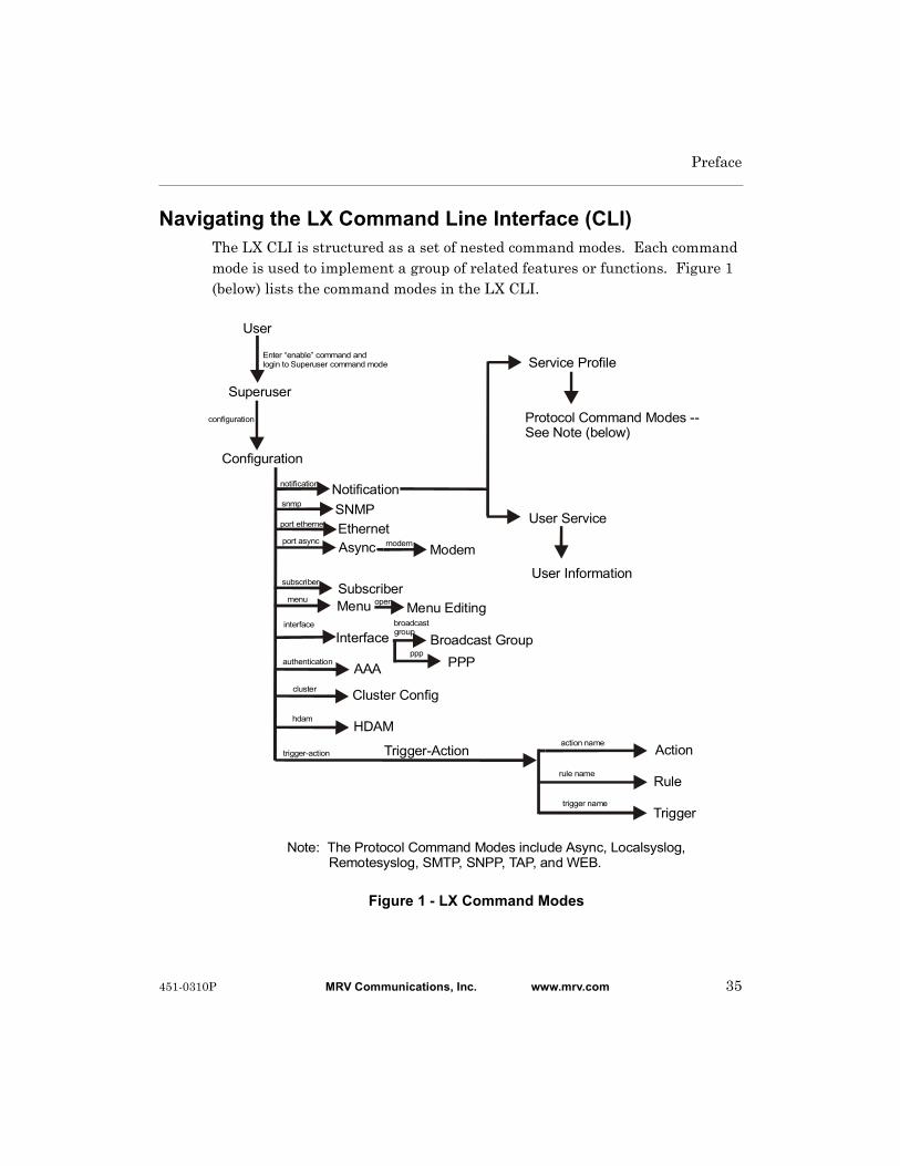
Preface
Navigating the LX Command Line Interface (CLI)The LX CLI is structured as a set of nested command modes. Each command mode is used to implement a group of related features or functions. Figure 1 (below) lists the command modes in the LX CLI.
Figure 1 - LX Command Modes
Trigger-Action
Configuration
Notification
Interface Broadcast Group
Subscriber
SNMP
Menu
User
Superuser
Enter “enable” command and login to Superuser command mode
Cconfiguration
Nnotification
Mmenu
Ssnmp
Ssubscriber
Iinterface Ibroadcast group
Modem
PPP
EthernetAsync Mmodem
Pppp
Pport ethernet
Pport async
Oopen Menu Editing
User Service
Service Profile
User Information
Protocol Command See Note (below)
Modes --
Note: The Protocol Command Modes include Async, Localsyslog, Remotesyslog, SMTP, SNPP, TAP, and WEB.
AAA
Action
Rule
Trigger
Aauthentication
trigger-actionMaction name
Trule name
Mtrigger name
Cluster Configcluster
hdamHDAM
451-0310P MRV Communications, Inc. www.mrv.com 35
Preface
Each command mode has its own command prompt (e.g., Config:0 >>) and its own set of commands.
Type a question mark (?) (or press the Tab key) at any of the LX CLI command prompts to display the commands that can be executed in the current command mode. For example, type a question mark at the Menu :0 >> prompt to display the commands that can be executed in the Menu command mode.
Type ^K to clear the current command line.
Except for the User command mode, each command mode is nested in a previous command mode. (The User command mode is the basic command mode of the LX CLI; you are in the User command mode when you log in to the LX unit.) For example, the Superuser command mode is nested in User command mode; the Configuration command mode is nested in the Superuser command mode, and so on.
To enter a nested command mode, you must enter the appropriate command from the previous command mode. For example, to enter the Configuration command mode you must enter the configuration command from the Superuser command mode.
You can use the exit command to return to the previous command mode. For example, you would enter the exit command in the Configuration command mode to return to the Superuser command mode.
You can execute the monitor/show commands in each of the LX command modes. The monitor/show commands are used to display global information for the LX unit.
The CLI supports execution of multiple level commands on the same line. For example:
InReach>> config port async 1 1 prompt tim
You can execute a command from any level, if you know the complete path.
The following section describes the LX command modes and the commands that are used to access each of them.
36 MRV Communications, Inc. www.mrv.com 451-0310P

Preface
Command Mode Descriptions• User Command Mode – Contains commands for performing user
functions on the LX unit.
• When you log on to the LX unit, you are in the User Command Mode.
• Command prompt: InReach:0 >
For more information, see “User Commands” on page 47.
• Superuser Command Mode – Contains commands for performing Superuser functions on the LX unit.
• Accessed by executing the enable command in the User Command Mode (see “enable” on page 57), and then entering the Superuser password when prompted. (The default Superuser password is system.)
• Command prompt: InReach:0 >>
For more information, see ““Superuser Commands” on page 249.
• Configuration Command Mode – Contains commands for configuring the LX unit at the server level and accessing nested command modes.
• Accessed by executing the configuration command in the Superuser Command Mode (see “configuration” on page 254).
• Command prompt: Config:0 >>
For more information, see “Configuration Commands” on page 307.
• Authentication, Accounting, and Authorization (AAA) Command Mode – Contains commands for configuring local and server-based authentication and authorization, and RADIUS and TACACS+ accounting, on the LX unit.
451-0310P MRV Communications, Inc. www.mrv.com 37

Preface
• Accessed by executing the aaa command in the Configuration Command Mode (see “aaa” on page 308).
• Command prompt: AAA:0 >>
For more information, see “Authentication, Accounting, and Authorization Commands” on page 403.
• Asynchronous Command Mode – Contains commands for configuring asynchronous ports on the LX unit.
• Accessed by executing the port async <port_number> command in the Configuration Command Mode (see “port async” on page 365).
• Command prompt: Async 4-4:0 >>
For more information, see “Asynchronous Commands” on page 537.
• Ethernet Command Mode – Contains commands for configuring the Ethernet port on the LX unit.
• Accessed by executing the port ethernet <port_number> command in the Configuration Command Mode (see “port ethernet” on page 366).
• Command prompt: Ether 1-1:0 >>
For more information, see “Ethernet Commands” on page 623.
• PPP Command Mode – Contains commands for configuring PPP sessions on the LX unit.
• Accessed by executing the ppp command in the Interface Command Mode (see “ppp” on page 523).
• Command prompt: PPP 4-4:0 >>
For more information, see “PPP Commands” on page 741.
38 MRV Communications, Inc. www.mrv.com 451-0310P
Preface
• Modem Command Mode – Contains commands for configuring modems on LX asynchronous ports.
• Accessed by executing the modem command in the Asynchronous Command Mode (see “modem” on page 577).
• Command prompt: Modem 4-4:0 >>
For more information, see “Modem Commands” on page 727.
• Subscriber Command Mode – Contains commands for configuring LX subscriber accounts.
• Accessed by executing the subscriber <subscriber_name> command in the Configuration Command Mode (see “subscriber” on page 389).
• Command prompt: Subs_mark >>
For more information, see “Subscriber Commands” on page 633.
• SNMP Command Mode – Contains commands for configuring SNMP on the LX unit.
• Accessed by executing the snmp command in the Configuration Command Mode (see “snmp” on page 384).
• Command prompt: Snmp:0 >>
For more information, see “SNMP Commands” on page 687.
• Interface Command Mode – Contains commands for configuring IP interfaces on the LX unit.
• Accessed by executing the interface <interface_number> command in the Configuration Command Mode (see “interface” on page 330).
• Command prompt: Intf 1-1:0 >>
For more information, “Interface Commands” on page 483.
451-0310P MRV Communications, Inc. www.mrv.com 39

Preface
• Menu Command Mode – Contains commands for creating, displaying, and accessing subscriber menus.
• Accessed by executing the menu command in the Configuration Command Mode (see “menu” on page 343).
• Command prompt: Menu :0 >>
For more information, see “Menu Commands” on page 781.
• Menu Editing Command Mode – Contains commands for creating and modifying entries in subscriber menus.
• Accessed by executing the open <menu_name> command in the Menu Command Mode (see “open” on page 787).
• Command prompt: menu_name-1:0 >>
For more information, see “Menu Commands” on page 781.
• Notification Command Mode – Contains commands for configuring the LX Notification Feature.
• Accessed by executing the notification command in the Configuration Command Mode (see “notification” on page 352).
• Command prompt: Notification:0 >>
For more information, see “Notification Commands” on page 831.
• Broadcast Group Command Mode – Contains commands for configuring Broadcast Groups on the LX unit.
• Accessed by executing the broadcast group <group_number> command in the Interface Command Mode (see “broadcast group” on page 500).
• Command prompt: BrGroups 6:0 >>
For more information, see “Broadcast Group Commands” on page 811.
40 MRV Communications, Inc. www.mrv.com 451-0310P

Preface
• Service Profile Command Mode – Contains commands for specifying the protocol for a Service Profile.
• Accessed by executing the profile service <profile_name> command in the Notification Command Mode (see “profile service” on page 845).
• Command prompt: Noti_Serv_Protocol:0 >>
For more information, see “Service Profile Commands” on page 849.
• Async Protocol Command Mode – Contains the port command for specifying the asynchronous port parameter for a Service Profile of the Async type.
• Accessed by executing the async command in the Service Profile Command Mode (see “async” on page 850).
• Command prompt: Noti_Serv_Async:0 >>
For more information, see “Async Protocol Commands” on page 863.
• Localsyslog Protocol Command Mode – Contains the file command for specifying the local file to which syslog messages will be sent under a Service Profile of the Localsyslog type.
• Accessed by executing the localsyslog command in the Service Profile Command Mode (see “localsyslog” on page 852).
• Command prompt: Noti_Serv_LSyslog:0 >>
For more information, see “Localsyslog Protocol Commands” on page 871.
• Remotesyslog Protocol Command Mode – Contains the host command for configuring the remote host IP address for a Service Profile of the Remotesyslog type.
• Accessed by executing the remotesyslog command in the Service Profile Command Mode (see “remotesyslog” on page 857).
451-0310P MRV Communications, Inc. www.mrv.com 41
Preface
• Command prompt: Noti_Serv_RSyslog:0 >>
For more information, see “Remotesyslog Protocol Commands” on page 879.
• SMTP Protocol Command Mode – Contains the server command for configuring the server for a Service Profile of the SMTP type.
• Accessed by executing the smtp command in the Service Profile Command Mode (see “smtp” on page 858).
• Command prompt: Noti_Serv_SMTP:0 >>
For more information, see “SMTP Protocol Commands” on page 887.
• SNPP Protocol Command Mode – Contains commands for configuring a Service Profile of the SNPP type.
• Accessed by executing the snpp command in the Service Profile Command Mode (see “snpp” on page 860).
• Command prompt: Noti_Serv_SNPP:0 >>
For more information, see “SNPP Protocol Commands” on page 897.
• TAP Protocol Command Mode – Contains commands for configuring a Service Profile of the TAP type.
• Accessed by executing the tap command in the Service Profile Command Mode (see “tap” on page 861).
• Command prompt: Noti_Serv_TAP:0 >>
For more information, see “TAP Protocol Commands” on page 905.
• WEB Protocol Command Mode – Contains the driver command for specifying the web driver for a Service Profile of the WEB type.
• Accessed by executing the web command in the Service Profile Command Mode (see “web” on page 862).
42 MRV Communications, Inc. www.mrv.com 451-0310P

Preface
• Command prompt: Noti_Serv_Web:0 >>
For more information, see “WEB Protocol Commands” on page 919.
• User Service Command Mode – Contains the service command for specifying a Service Profile for a User Profile.
• Accessed by executing the profile user <username> command in the Notification Command Mode (see “profile user” on page 846).
• Command prompt: Noti_User_Service:0 >>
For more information, see “User Service Commands” on page 927.
• User Information Command Mode – Contains commands for specifying the contact, facility, and priority parameters of a User Profile.
• Accessed by executing the service command in the User Service Command Mode (see “service” on page 933).
• Command prompt: Noti_User_Info:0 >>
For more information, see “User Information Commands” on page 935.
• Trigger-Action Command Mode – Contains commands for creating, or accessing, Actions, Rules, and Triggers for the Trigger-Action Feature.
• Accessed by executing the trigger-action command in the Notification Command Mode (see “trigger-action” on page 396).
• Command prompt: Trigger-Action:0 >>
For more information, see “Trigger-Action Commands” on page 945.
451-0310P MRV Communications, Inc. www.mrv.com 43
Preface
• Rule Command Mode – Contains commands for enabling, disabling, and specifying Actions and Triggers for Rules.
• Accessed by executing the rule name <rule_name> command in the Trigger-Action Command Mode (see “rule name” on page 951).
• Command prompt: Rule_AC7TurnOnRule:0 >>
For more information, see “Rule Commands” on page 957.
• Action Command Mode – Contains the command command for specifying an LCX CLI command for an Action.
• Accessed by executing the action name command in the Trigger-Action Command Mode (see “action name” on page 946).
• Command prompt: Action_TurnOnAC7:0 >>
For more information, see “Action Commands” on page 969.
• Trigger Command Mode – Contains commands for specifying the conditions for triggers.
• Accessed by executing the trigger name command in the Trigger-Action Command Mode (see “trigger name” on page 956).
• Command prompt: Trigger_TempPortCT30:0 >>
For more information, see “Trigger Commands” on page 977.
• Cluster Command Mode – Contains commands for creating and monitoring clusters.
• Accessed by executing the cluster command in the Configuration Command Mode.
• Command prompt: Cluster:0 >>
For more information, see “Cluster Configuration and Control Commands” on page 1003.
44 MRV Communications, Inc. www.mrv.com 451-0310P
Preface
Online HelpThe question mark character (?), and the Tab key, are used to display online help in the LX Command Line Interface (CLI). The following guidelines will help you to navigate the online help system:
• Type the ? character (or press the Tab key) at the command prompt in any command mode to display the first keyword of each command that can be executed in that command mode. For example, the following is displayed when you type the ? character at the User mode command prompt:
clear Clear screen and reset terminal line
enable Turn on privileged commands
exit Exit up one level
menu Menu utility
monitor Monitor running system information
no Negate a command
outlet Manipulate outlets
ping Send echo messages
shell Run a shell as Superuser
show Show running system information
ssh Secure Shell (3DES/Blowfish)
telnet Open a telnet connection
terminal Set the terminal type
<cr>
• Type the ? character (or press the Tab key) after the displayed keyword to list the options for that keyword. For example, type show? to list the options of the show keyword. You could then type show port? to list the next item in the syntax of the show port command.
451-0310P MRV Communications, Inc. www.mrv.com 45

Preface
Using the Function KeysThe LX Command Line Interface (CLI) supports the following function keys:
• Tab key – Completes a partially typed command. For example, if you type the tab key after you type show ve at the Superuser command prompt, the show version command will be executed.
• Up arrow – Recalls the last command.
• Ctrl-F – Moves forward to the next session.
• Ctrl-B – Moves back to the previous session.
• Ctrl-L – Returns you to the Local Command Mode.
Related DocumentsFor detailed information on using the LX unit, refer to the LX-Series Configuration Guide (P/N 451-0311).
For more information on the LX-8000 hardware, refer to Getting Started with the LX-8000 Series (P/N 451-0331).
The LX-8000 Quick Start Instructions (P/N 451-0332) describes how to get the LX-8000 unit up and running.
For more information on the LX-4000 hardware, refer to Getting Started with the LX-4000 Series (P/N 451-0308).
The LX-4000 Quick Start Instructions (P/N 451-0312) describes how to get the LX-4000 unit up and running.
For more information on the LX-1000 hardware, refer to Getting Started with the LX-1000 Series (P/N 451-0320).
The LX-1000 Quick Start Instructions (P/N 451-0321) describes how to get the LX-4000 unit up and running.
46 MRV Communications, Inc. www.mrv.com 451-0310P

Chapter 1
User Commands
The User commands are executed in the User command mode. The User command mode is in effect immediately upon logging in to the LX unit.
The User Command prompt indicates that the LX unit is in the User command mode. The format of the User command prompt is as follows:
<username>:<session_number> >
where <username> is the username that was entered at the Login: prompt.
<session_number> is the session number of the current connection.
For example, in the InReach:0 > prompt, the username is InReach and the session number is 0.
The rest of this chapter describes the commands that you can enter in the User command mode.
451-0310P MRV Communications, Inc. www.mrv.com 47

Clear the screen.
Syntax
clear
Example
clear
clear
48 MRV Communications, Inc. www.mrv.com 451-0310P
Issues a CLI command to any remote cluster member without having to log in to that cluster member.
Syntax
cluster command all | <ip_address> <cluster_command>
Where Means
Examples
InReach:0>>cluster command all enable system conf port async 1
InReach:0>>cluster command 120.130.222.33 enable system conf port 1
cluster command
all Runs the command across all clusters.
ip-address The IP address of the cluster member to which you want to send a command.
cluster_command The cluster command you want to send to the cluster member.
451-0310P MRV Communications, Inc. www.mrv.com 49
Searches all nodes in a cluster for a specific port name or serial access mode. Each search displays a different results screen, depending on what field you searched for.
Syntax
cluster search portname <port_name> | <access>
Where Means
Usage Guidelines
This command requires that a common cluster secret be configured, and that the member IP address be configured for the cluster, or an error message is displayed.
Examples
cluster search portname Port_1
cluster search access ir5150
cluster search
port_name The name of the port you want to search. The port name is case sensitive, and must be typed with initial capitalization and an underscore between the word “Port” and the port number.
access The access method for the port. Options are ir4800 and ir5150.
50 MRV Communications, Inc. www.mrv.com 451-0310P
Configures an escape sequence used on a connect port async session. Use connect escape to escape the session. The default value is ^Z. To set the escape character back to the default value, enter default connect escape.
Syntax
connect escape ^<character>
Where Means
Examples
connect escape ^A
default connect escape
connect escape
character The escape character (A - Z).
451-0310P MRV Communications, Inc. www.mrv.com 51

Opens a port async connection to a serial port on the same physical LX unit.
Syntax
connect port async <port_number>
Where Means
Examples
connect port async 2
connect port async 6
connect port async
port-number The port number to which the connection is being made.
52 MRV Communications, Inc. www.mrv.com 451-0310P

Initiates a Dialback connection to a host.
NOTE: THIS COMMAND EXISTS IN THE CLI, BUT IT SHOULD NEVER BE EXECUTED BY A USER! This command is executed in the background when the user executes the dial reverse command. For more information on the dial reverse command, refer to “dial reverse” on page 56.
Syntax
dial back number <number> token <token_num>
Where Means
Example
dial back number 1234567890 token 4325
dial back
number The number that is dialed to initiate the connection.
token_num A numeric value that is used to identify the modem on which the Dialback call is expected.
451-0310P MRV Communications, Inc. www.mrv.com 53

Initiates a connection to a host by direct-dialing a number.
Syntax
dial direct number <number> [login <login_name>] [password <password_name>]
Where Means
Usage Guidelines
This feature allows you to execute a command from the CLI to dial a remote site without having to find an available modem on the LX. The LX chooses the first available modem from the modem pool.
In order to use this feature, you must specify a modem pool for the LX unit. For more information, refer to the pool enable command on page 738.
The following status messages will be displayed if you execute this command with a Login name and a password:
Dial out on modem 10
Sending login
Sending password
When the Sending password prompt is displayed, you must press a key to get the CLI prompt of the remote LX unit.
Examples
dial direct number 1234567890
dial direct number 1234567890 login HenryS
dial direct number 1234567890 login JSmithers password JHoiu45fgij
dial direct
number The number that is dialed to initiate the connection.
login Log in to the dialed host using the name that you specify in the login_name field. Refer to “Usage Guidelines” (below) for more information.
login_name The Login Name that you will use for logging in to the dialed host.
password Log in to the dialed host using the password that you specify in the password_name field. Refer to “Usage Guidelines” (below) for more information.
password_name The password that you will use for logging in to the remote host.
54 MRV Communications, Inc. www.mrv.com 451-0310P
Initiates a dialed connection to a host via a PPP Link.
NOTE: THIS COMMAND SHOULD NOT BE EXECUTED BY A USER FROM THE CLI! IT SHOULD ONLY BE USED AS THE SPECIFIED COMMAND FOR AN ACTION. (Refer to “command” on page 970 for more information on specifying a command for an Action.)
Syntax
dial ppp number <number> interface <interface_num>
Where Means
Usage Guidelines
When this command is executed, the LCP state and IPCP state for the specifed IP interface must be “Closed”. If the LCP state and IPCP state are “Closed”, the LX will dial out the port that has been bound to the port for PPP.
Example
dial ppp number 1234535437 interface 3
dial ppp
number The number that is dialed to initiate the connection.
interface_num The interface number of an IP interface that has been configured for PPP. This IP interface must be bound to an asynchronous port for PPP Links. Refer to “bind port async protocol ppp” on page 495 for more information on binding an IP interface to an asynchronous port for PPP Links.
451-0310P MRV Communications, Inc. www.mrv.com 55

Initiates a connection to a remote LX unit by reverse dialing. For more information on reverse dialing, refer to “Usage Guidelines” (below).
Syntax
dial reverse number <number> login <login_name> password <password_name>
[phone <phone_num>] [timeout <timeout_setting>]
Where Means
Usage Guidelines
Under reverse dialing, the LX unit dials out to the remote LX using the first available modem from the Modem Pool. The modem for the remote LX validates the subscriber login and calls back the subscriber
In order to use this feature, you must specify a modem pool for the LX unit. For more information, refer to the pool enable command on page 738.
NOTE: Dialback should be disabled for your subscriber account when you execute this command. To disable Dialback for your subscriber account, execute the no dialback command in the Subscriber Command Mode.
Example
dial reverse number 1234567890 login HenryW password utdls2346ma phone 1908765432 timeout 40
dial reverse
number The number of the remote LX unit.
login_name The Login Name that you will use for logging in to the remote LX unit. (This must be the same as your Login Name on the local LX unit.)
password_name The password that you will use for logging in to the remote host. (This must be the same as your password on the local LX unit.)
phone_num The number of a modem on the local LX. The remote LX will call you back at this number. (The default value is the Dialback number that is configured for your subscriber account.)
timeout_setting The length of time (in seconds) that is allowed to complete the connection. (The default value is the idletime in your subscriber account.)
56 MRV Communications, Inc. www.mrv.com 451-0310P

Displays a password prompt for logging into the Superuser Command Mode. When you are logged into Superuser mode, you can execute the Superuser commands. Refer to “Superuser Commands” on page 249 for more information on the Superuser commands.
NOTE: In order to access (log in) to the Superuser Command Mode, your Security Level must be Superuser. For more information, refer to “Displaying Your Security Level” (below).
Syntax
enable
Usage Guidelines
When you execute the enable command, the Password: prompt is displayed:
To enter Superuser mode, you must enter a Superuser password at the Password: prompt. The default Superuser password is system.
The Superuser prompt is displayed when you are in Superuser mode. The Superuser prompt is in the following format:
<username>:<session_number> >>
where <username> is the username that was entered at the Login: prompt.
<session_number> is the session number of the current connection.
For example, in the InReach:0 >> prompt, the username is InReach and the session number is 0.
Example
enable
Displaying Your Security Level
Your Security Level is displayed in the Security field of the Subscriber Characteristics Screen. An example of the Subscriber Characteristics Screen appears in Figure 93 on page 203.
Use the monitor/show subscriber command to display the Subscriber Characteristics Screen. Refer to “monitor/show subscriber” on page 202 for more information.
enable
451-0310P MRV Communications, Inc. www.mrv.com 57

When the exit command is executed in User Mode, it exits the LX CLI and closes the connection to the LX unit.
Syntax
exit
Usage Guidelines
The exit command can be issued in all of the LX Command Modes. However, the effect of the exit command varies, depending on the mode from which it is issued.
As noted above, issuing the exit command in User Mode exits the LX CLI and closes the connection to the LX unit.
Issuing the exit command in any mode other than User returns the user to the previous command mode. For example, issuing the exit command in Superuser Mode returns the user to User Mode; issuing the exit command in Configuration Mode returns the user to Superuser Mode, and so on.
Example
exit
exit
58 MRV Communications, Inc. www.mrv.com 451-0310P
Changes the active Subscriber Session Mode from CLI to Menu. When the active Subscriber Session Mode is changed to Menu, your Menu is displayed and active.
Syntax
menu
Usage Guidelines
You can select any option from your displayed and active Menu. You can exit the active Menu by typing the “Logout” control key.
In order to execute this command, you must have a Menu Name configured for your Subscriber account. (Refer to “menu name” on page 667 to configure a Menu Name for a Subscriber account.)
The Login Mode field of the Subscriber Characteristics Screen indicates whether the subscriber will be presented with the CLI, or a menu, when he or she logs in. The name of the Subscriber Menu (If any) is displayed in the Menu Name field of the Subscriber Characteristics Screen. An example of the Subscriber Characteristics Screen appears in Figure 93 on page 203.
Use the monitor/show subscriber command to display the Subscriber Characteristics Screen. Refer to “monitor/show subscriber” on page 202 for more information.
Example
menu
menu
451-0310P MRV Communications, Inc. www.mrv.com 59

Sends a message to the console of the user(s) who are currently logged in to the LX unit.
Syntax
message user [<user_name>]|all [<message_text>]
Where Means
Usage Guidelines
An interactive user (the user must be typing commands or type ENTER) will be notified whenever they receive a new message via the CLI. This message will tell them that they have a new message, and how many total messages are available for reading. When a message is read, an acknowledgement is automatically sent to the sender of the message to tell them that this message has been read. If a user logs out before reading all of his or her messages, these messages are deleted and negative acknowledgement is sent to the sender of each.
Examples
message user markw This is a test
message user all The system will go down at 15:30!!!
message user
user_name The LX username of the user to whom the message is to be sent.
all Send the message to all LX users that are currently logged in.
message_text The message that is to be sent to the logged-in user(s). This can be an ASCII string of any length.
60 MRV Communications, Inc. www.mrv.com 451-0310P

Displays the audit log for a port or a subscriber.
The show audit log command displays a static version of the Audit Log Screen; the information in the Audit Log Screen is the information that was in effect when the show audit log command was executed.
The monitor audit log command displays an active version of the Audit Log Screen; the information in the screen is updated with each change to the data that is displayed in the screen.
Syntax
monitor audit log [<port_number>]|[<subscriber_name>]
show audit log [<port_number>]|[<subscriber_name>]
Where Means
Usage Guidelines
If you execute show audit log for a subscriber, the screen will only contain audit log data for the subscriber in question.
If you execute show audit log for a port, the screen will contain audit log data for all of the subscribers that are logged in at the port.
Examples
monitor audit log
show audit log
monitor audit log 5
show audit log 5
monitor audit log mark
show audit log mark
monitor/show audit log
port_number Specifies an asynchronous port number on the LX unit.
subscriber_name Specifies an LX subscriber name.
451-0310P MRV Communications, Inc. www.mrv.com 61
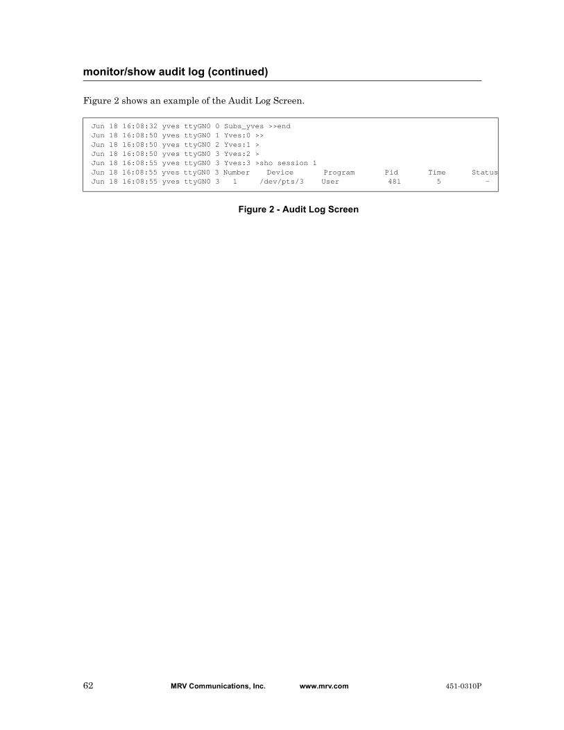
Figure 2 shows an example of the Audit Log Screen.
Figure 2 - Audit Log Screen
monitor/show audit log (continued)
Jun 18 16:08:32 yves ttyGN0 0 Subs_yves >>endJun 18 16:08:50 yves ttyGN0 1 Yves:0 >>Jun 18 16:08:50 yves ttyGN0 2 Yves:1 >Jun 18 16:08:50 yves ttyGN0 3 Yves:2 >Jun 18 16:08:55 yves ttyGN0 3 Yves:3 >sho session 1Jun 18 16:08:55 yves ttyGN0 3 Number Device Program Pid Time StatusJun 18 16:08:55 yves ttyGN0 3 1 /dev/pts/3 User 481 5 -
62 MRV Communications, Inc. www.mrv.com 451-0310P

Displays the day, date, time, and timezone for the LX unit.
The show clock command displays a static version of the Clock Screen; the information in the Clock Screen is the information that was in effect when the show clock command was executed.
The monitor clock command displays an active version of the Clock Screen; the information in the Clock Screen is updated with each passing second.
Syntax
monitor clock
show clock
Examples
monitor clock
show clock
Figure 3 shows an example of the Clock Screen.
Figure 3 - Clock Screen
monitor/show clock
Mon, 23 Jun 2003 11:46:40 US/EASTERN
451-0310P MRV Communications, Inc. www.mrv.com 63

Displays the command log for a port or for a subscriber.
The show command log command displays a static version of the Command Log Screen; the information in the Command Log Screen is the information that was in effect when the show command log command was executed.
The monitor command log command displays an active version of the Command Log Screen; the information in the screen is updated with each change to the data that is displayed in the screen.
Syntax
monitor command log [<port_number>]|[<subscriber_name>]
show command log [<port_number>]|[<subscriber_name>]
Examples
monitor command log
show command log
monitor command log 4
show command log 4
monitor command log mark
show command log mark
Figure 4 shows an example of the Command Log Screen.
Figure 4 - Command Log Screen
monitor/show command log
Jun 11 12:47:30 demo 0 endJun 11 12:47:33 demo 0 sho command logJun 11 12:49:21 demo 23 modemJun 11 12:49:29 demo 23 endJun 11 12:49:39 demo 23 show command log demo
64 MRV Communications, Inc. www.mrv.com 451-0310P

Displays the contents of the LX configuration tables or the configuration data from the Non-Volatile memory of the LX unit.
The show configuration command displays a static version of the Configuration Data Screen; the information in the Configuration Data Screen is the information that was in effect when the show configuration command was executed.
The monitor configuration command displays an active version of the Configuration Data Screen; the information in the screen is updated with each change to the data that is displayed in the screen.
Syntax
monitor configuration [interface] [port async] [port ethernet]
[subscriber] [system]
show configuration [interface] [port async] [port ethernet]
[subscriber] [system]
Where Means
Usage Guidelines
If this command is executed without a modifier, all of the configuration tables are displayed.
Examples
monitor configuration
monitor configuration interface
monitor configuration port async
monitor configuration port ethernet
monitor configuration subscriber
monitor configuration system
monitor/show configuration
interface Display the contents of the Interface configuration table.
port async Display the contents of the asynchronous port configuration table.
port ethernet Display the contents of the ethernet port configuration table.
subscriber Display the contents of the subscriber configuration table.
system Display the contents of the system configuration table.
451-0310P MRV Communications, Inc. www.mrv.com 65

show configuration
show configuration interface
show configuration port async
show configuration port ethernet
show configuration subscriber
show configuration system
Figure 5 shows an example of the Configuration Data Screen.
Figure 5 - Configuration Data Screen
monitor/show configuration (continued)
Signature is :a1326c7cf50dd779086e0a90843fdke94398kj9In-Reach Configuration version 0.0.34, Linux kernel version 2.4.10
System.SystemName.0 TYPE STRING VALUE "InReach LX-1"System.SystemLocation.0 TYPE STRING VALUE "Middle of NoWhere"System.TimeZone.0 TYPE STRING VALUE "UTC"System.UseNtp.0 TYPE BOOL VALUE "Disabled"System.UseLpd.0 TYPE BOOL VALUE "Disabled"System.SnmpLocation.0 TYPE STRING VALUE ""System.SnmpPort.0 TYPE SHORT VALUE "161"System.SnmpLog.0 TYPE BOOL VALUE "Disabled"System.SnmpTransport.0 TYPE OCTET VALUE "0"System.SysLogAddr.0 TYPE IPADDR VALUE "0.0.0.0"System.UseSsh.0 TYPE BOOL VALUE "Disabled"System.UseRad.0 TYPE BOOL VALUE "Disabled"System.UseRadAcct.0 TYPE BOOL VALUE "Disabled"System.RadPort.0 TYPE SHORT VALUE "1812"System.RadAcctPort.0 TYPE SHORT VALUE "1813"System.RadPrimAuth.0 TYPE IPADDR VALUE "1.1.1.1"System.RadPrimSecret.0 TYPE STRING VALUE ""System.RadSecAuth.0 TYPE IPADDR VALUE "1.1.1.2"System.RadSecSecret.0 TYPE STRING VALUE ""System.RadPrimAcct.0 TYPE IPADDR VALUE "1.1.1.1"Type a key to continue, q to quit
66 MRV Communications, Inc. www.mrv.com 451-0310P
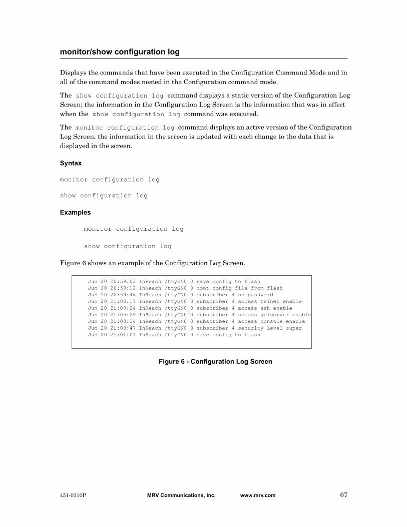
Displays the commands that have been executed in the Configuration Command Mode and in all of the command modes nested in the Configuration command mode.
The show configuration log command displays a static version of the Configuration Log Screen; the information in the Configuration Log Screen is the information that was in effect when the show configuration log command was executed.
The monitor configuration log command displays an active version of the Configuration Log Screen; the information in the screen is updated with each change to the data that is displayed in the screen.
Syntax
monitor configuration log
show configuration log
Examples
monitor configuration log
show configuration log
Figure 6 shows an example of the Configuration Log Screen.
Figure 6 - Configuration Log Screen
monitor/show configuration log
Jun 20 20:59:03 InReach /ttyGN0 0 save config to flashJun 20 20:59:12 InReach /ttyGN0 0 boot config file from flashJun 20 20:59:46 InReach /ttyGN0 0 subscriber 4 no passwordJun 20 21:00:17 InReach /ttyGN0 0 subscriber 4 access telnet enableJun 20 21:00:24 InReach /ttyGN0 0 subscriber 4 access ssh enableJun 20 21:00:29 InReach /ttyGN0 0 subscriber 4 access guiserver enableJun 20 21:00:34 InReach /ttyGN0 0 subscriber 4 access console enableJun 20 21:00:47 InReach /ttyGN0 0 subscriber 4 security level superJun 20 21:01:01 InReach /ttyGN0 0 save config to flash
451-0310P MRV Communications, Inc. www.mrv.com 67
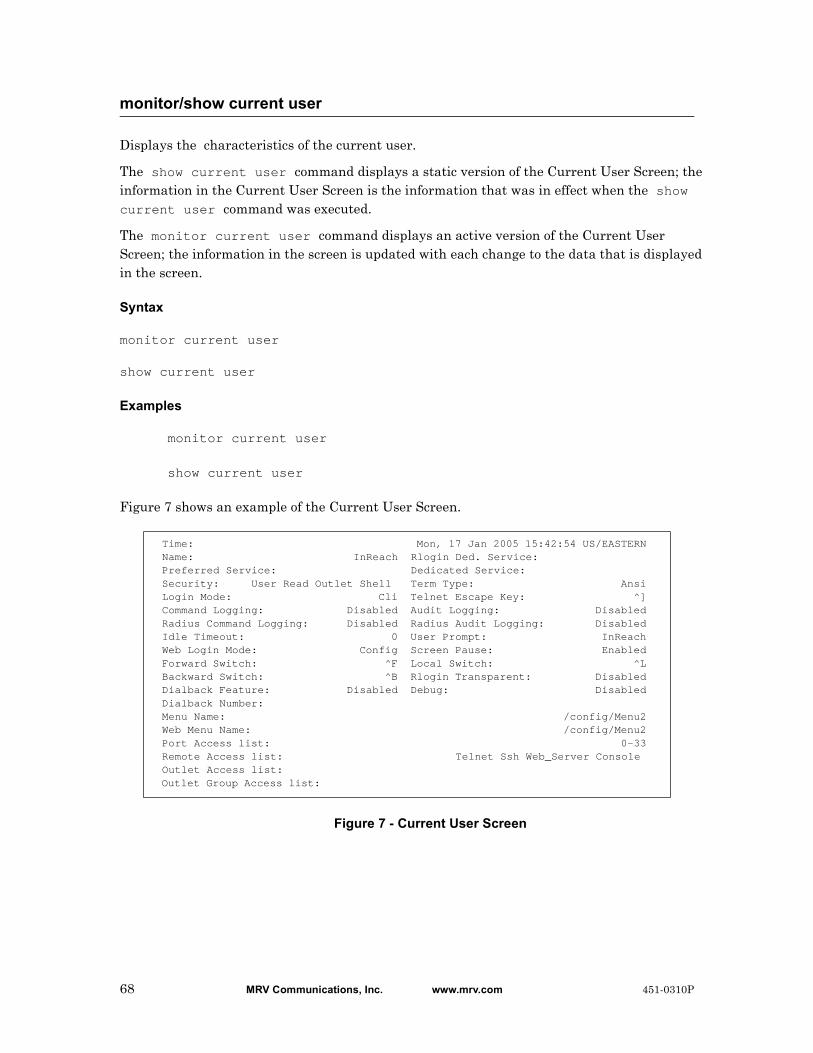
Displays the characteristics of the current user.
The show current user command displays a static version of the Current User Screen; the information in the Current User Screen is the information that was in effect when the show current user command was executed.
The monitor current user command displays an active version of the Current User Screen; the information in the screen is updated with each change to the data that is displayed in the screen.
Syntax
monitor current user
show current user
Examples
monitor current user
show current user
Figure 7 shows an example of the Current User Screen.
Figure 7 - Current User Screen
monitor/show current user
Time: Mon, 17 Jan 2005 15:42:54 US/EASTERN Name: InReach Rlogin Ded. Service: Preferred Service: Dedicated Service: Security: User Read Outlet Shell Term Type: Ansi Login Mode: Cli Telnet Escape Key: ^] Command Logging: Disabled Audit Logging: Disabled Radius Command Logging: Disabled Radius Audit Logging: Disabled Idle Timeout: 0 User Prompt: InReach Web Login Mode: Config Screen Pause: Enabled Forward Switch: ^F Local Switch: ^L Backward Switch: ^B Rlogin Transparent: Disabled Dialback Feature: Disabled Debug: Disabled Dialback Number: Menu Name: /config/Menu2 Web Menu Name: /config/Menu2 Port Access list: 0-33 Remote Access list: Telnet Ssh Web_Server Console Outlet Access list: Outlet Group Access list:
68 MRV Communications, Inc. www.mrv.com 451-0310P

monitor/show current user (continued)
Field Description
Time The time at which you created the show screen.
Name The name under which the subscriber is logged in.
Preferred Service The service to which the subscriber will be connected when the subscriber makes a connect request without specifying a service.
Security The level of security that the subscriber has. The possible values are None and Superuser.
Login Mode Indicates whether the subscriber will be in the CLI, or his Menu, when he or she logs in to the LX unit.
Command Logging Indicates whether the command logging feature is Enabled or Disabled for the subscriber.
Radius Command Logging
Indicates whether the radius command logging feature is Enabled or Disabled for the subscriber.
Idle Timeout The length of time that the subscriber can go without entering keyboard data before she is logged out.
Web Login Mode The login mode that a subscriber can access. The options are Configuration and Menu.
Forward Switch The keyboard character that the subscriber types to switch to the next session.
Backward Switch The keyboard character that the subscriber types to switch to the previous session.
Dialback Feature Indicates whether or not the subscriber requires a dialback script in order to be logged in. (The dialback script contains commands that cause a modem to dial a designated telephone number.) The allowable values are Enabled and Disabled.
Dialback Number The telephone number that the LX modem will dial when the subscriber makes a Dialback call to the LX unit.
Menu Name The name of the Menu assigned to the subscriber account.
Web Menu Name The name of the Web Menu assigned to the subscriber account. This name can be up to 22 characters long.
Port Access List
The LX ports that the user can access.
Remote Access List
The methods that the user can use to make remote connections.
Outlet Access List The individual outlets that the subscriber is authorized to manage.
451-0310P MRV Communications, Inc. www.mrv.com 69

monitor/show current user (continued)
Outlet Group Access List
The outlet groups that the subscriber is authorized to manage.
Rlogin Ded. Service
The rlogin service to which the subscriber is permanently assigned.
Dedicated Service The service to which the subscriber is permanently assigned.
Term Type The type of terminal emulation. Options are VT100 and ANSI.
Telnet Escape Key The telnet break sequence, which can be anything you designate. The default is Ctrl right bracket.
Audit Logging Indicates whether the Audit Logging Feature is Enabled or Disabled.
Radius Audit Logging
Indicates whether the Radius Audit Logging Feature is Enabled or Disabled.
User Prompt The subscriber-specific field of the subscriber User prompt. For example, for a subscriber prompt of InReach:0 >, the subscriber-specific field is InReach.
Screen Pause Indicates whether or not the screen is enabled to pause after 26 lines of output are displayed.
Local Switch The keyboard character that the subscriber types to return to the local command mode.
RLogin Transparent
Indicates whether rlogin is Enabled or Disabled.
Debug Indicates whether Debug is Enabled or Disabled.
70 MRV Communications, Inc. www.mrv.com 451-0310P
Displays (by port number) the contents of the databuffer for the LX unit.
The show databuffer log <port_number> command displays a static version of the Databuffer Log Port Screen; the information in the Databuffer Log Port Screen is the information that was in effect when the show databuffer log <port_number> command was executed.
The monitor databuffer log <port_number> command displays an active version of the Databuffer Log Port Screen; the information in the screen is updated with each change to the data that is displayed in the screen.
Syntax
monitor databuffer log <port_number>
show databuffer log <port_number>
Where Means
Examples
monitor databuffer log <port_number>
show databuffer log <port_number>
monitor/show databuffer log
port_number The number of the port on which you want to retrieve information from the common log.
451-0310P MRV Communications, Inc. www.mrv.com 71

Figure 8 shows an example of the Databuffer Log Port Screen.
Figure 8 - Databuffer Log Port Screen
monitor/show databuffer log (continued)
Jan 28 10:59:48 In-Reach [portasync34][7633]: #
Jan 28 10:59:48 In-Reach [portasync34][7633]: #
Jan 28 10:59:54 In-Reach [portasync34][7633]: # exit
Jan 28 10:59:54 In-Reach [portasync34][7633]:
Jan 28 10:59:55 In-Reach [portasync34][7633]: eagle console login:
Jan 28 11:00:22 In-Reach [portasync34][7633]: eagle console login: admin112
Jan 28 11:00:26 In-Reach [portasync34][7633]: Password:
Jan 28 11:00:26 In-Reach [portasync34][7633]: Last login: Thu Jan 27 16:18:06 on console
Jan 28 11:00:26 In-Reach [portasync34][7633]: Jan 28 10:54:02 eagle login: ADMIN112 LOGIN /
dev/console
Jan 28 11:00:26 In-Reach [portasync34][7633]: Sun Microsystems Inc. SunOS 5.8 Generic
Patch February 2004
Jan 28 11:00:28 In-Reach [portasync34][7633]: #
Jan 28 11:00:28 In-Reach [portasync34][7633]: #
Jan 28 11:00:36 In-Reach [portasync34][7633]: # Type 'go' to resume
Jan 28 11:00:37 In-Reach [portasync34][7633]: ok
Jan 28 11:00:38 In-Reach [portasync34][7633]: ok
Jan 28 11:00:41 In-Reach [portasync34][7633]: ok go
Jan 28 11:00:41 In-Reach [portasync34][7633]:
Jan 28 11:00:42 In-Reach [portasync34][7633]: #
Jan 28 11:00:46 In-Reach [portasync34][7633]: # exit
Jan 28 11:00:46 In-Reach [portasync34][7633]:
72 MRV Communications, Inc. www.mrv.com 451-0310P
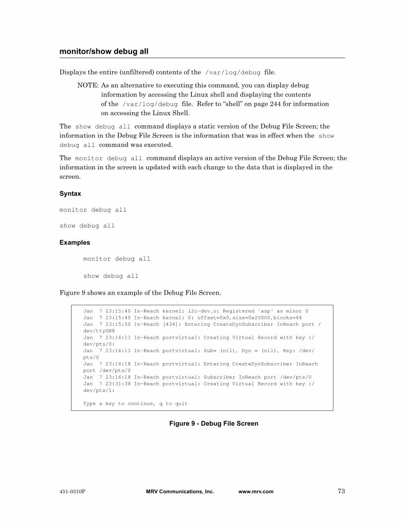
Displays the entire (unfiltered) contents of the /var/log/debug file.
NOTE: As an alternative to executing this command, you can display debug information by accessing the Linux shell and displaying the contents of the /var/log/debug file. Refer to “shell” on page 244 for information on accessing the Linux Shell.
The show debug all command displays a static version of the Debug File Screen; the information in the Debug File Screen is the information that was in effect when the show debug all command was executed.
The monitor debug all command displays an active version of the Debug File Screen; the information in the screen is updated with each change to the data that is displayed in the screen.
Syntax
monitor debug all
show debug all
Examples
monitor debug all
show debug all
Figure 9 shows an example of the Debug File Screen.
Figure 9 - Debug File Screen
monitor/show debug all
Jan 7 23:15:40 In-Reach kernel: i2c-dev.o: Registered 'asp' as minor 0Jan 7 23:15:40 In-Reach kernel: 0: offset=0x0,size=0x20000,blocks=64Jan 7 23:15:50 In-Reach [434]: Entering CreateDynSubscriber InReach port /dev/ttyGN8Jan 7 23:16:11 In-Reach portvirtual: Creating Virtual Record with key :/dev/pts/0:Jan 7 23:16:11 In-Reach portvirtual: Sub= (nil), Dyn = (nil), Key: /dev/pts/0Jan 7 23:16:18 In-Reach portvirtual: Entering CreateDynSubscriber InReach port /dev/pts/0Jan 7 23:16:18 In-Reach portvirtual: Subscriber InReach port /dev/pts/0Jan 7 23:31:38 In-Reach portvirtual: Creating Virtual Record with key :/dev/pts/1:
Type a key to continue, q to quit
451-0310P MRV Communications, Inc. www.mrv.com 73

When debug flash is enabled, various flash memory write messages generated by the LX will be written to the debug file. The show debug flash command displays the flash filtered contents of the /var/log/debug file.
NOTE: As an alternative to executing this command, you can display debug information by accessing the Linux shell and displaying the contents of the /var/log/debug file. Refer to “shell” on page 244 for information on accessing the Linux Shell.
The show debug flash command displays a static version of the Debug Flash Screen; the information in the Debug Flash Screen is the information that was in effect when the show debug flash command was executed.
The monitor debug flash command displays an active version of the Debug Flash Screen; the information in the screen is updated with each change to the data that is displayed in the screen.
Syntax
monitor debug flash
show debug flash
Examples
monitor debug flash
show debug flash
Figure 10 shows an example of the Debug Flash Screen.
Figure 10 - Debug Flash Screen
monitor/show debug flash
May 6 16:43:05 fd = 7, start = 0x760000, lock = 0, count = 1May 6 16:43:05 region = 0: start = 0x760000, r->offset = 0x0, r->erasesize = 0x20000, r->numblocks = 64May 6 16:43:05 start found in region 0May 6 16:43:05 erase.length = 0x20000, cur = 0x780000, totalblocks = 1May 6 16:43:05 Unlocking: erase.start = 0x760000, erase.length = 0x20000May 6 16:43:06 fd = 7, start = 0x760000, lock = 1, count = 1May 6 16:43:06 region = 0: start = 0x760000, r->offset = 0x0, r->erasesize = 0x20000, r->numblocks = 64May 6 16:43:06 start found in region 0May 6 16:43:06 erase.length = 0x20000, cur = 0x780000, totalblocks = 1May 6 16:43:06 Locking: erase.start = 0x760000, erase.length = 0x20000
74 MRV Communications, Inc. www.mrv.com 451-0310P
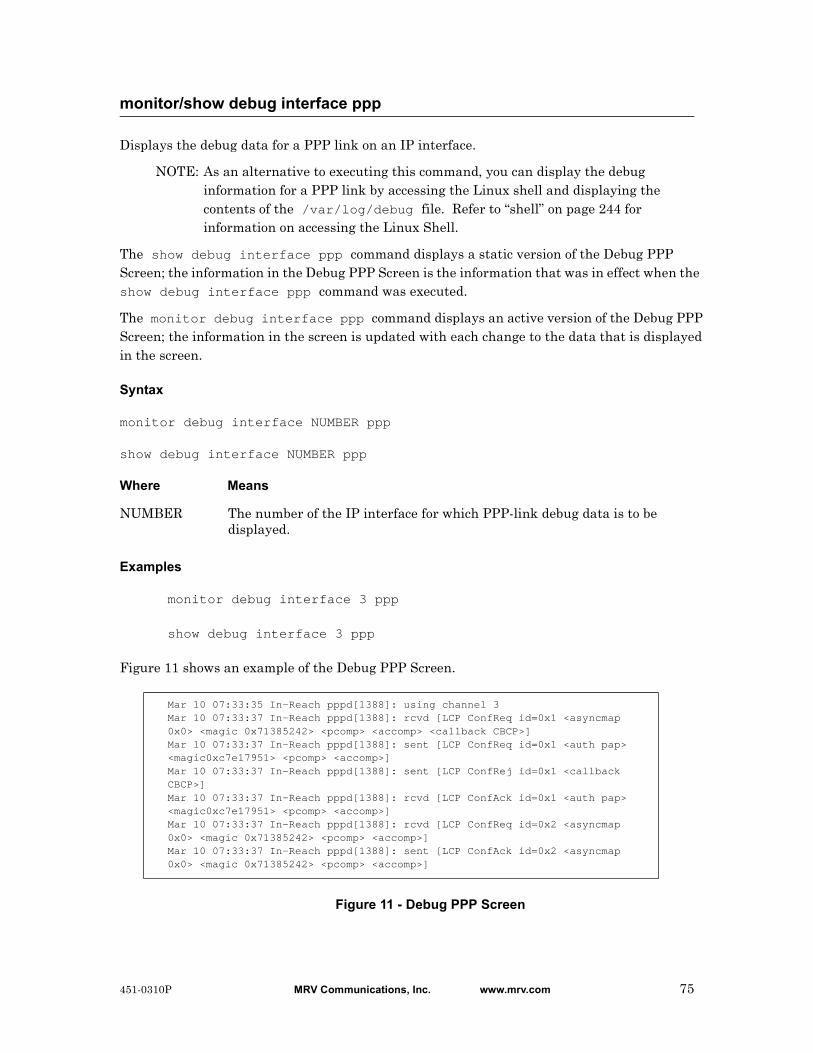
Displays the debug data for a PPP link on an IP interface.
NOTE: As an alternative to executing this command, you can display the debug information for a PPP link by accessing the Linux shell and displaying the contents of the /var/log/debug file. Refer to “shell” on page 244 for information on accessing the Linux Shell.
The show debug interface ppp command displays a static version of the Debug PPP Screen; the information in the Debug PPP Screen is the information that was in effect when the show debug interface ppp command was executed.
The monitor debug interface ppp command displays an active version of the Debug PPP Screen; the information in the screen is updated with each change to the data that is displayed in the screen.
Syntax
monitor debug interface NUMBER ppp
show debug interface NUMBER ppp
Where Means
Examples
monitor debug interface 3 ppp
show debug interface 3 ppp
Figure 11 shows an example of the Debug PPP Screen.
Figure 11 - Debug PPP Screen
monitor/show debug interface ppp
NUMBER The number of the IP interface for which PPP-link debug data is to be displayed.
Mar 10 07:33:35 In-Reach pppd[1388]: using channel 3Mar 10 07:33:37 In-Reach pppd[1388]: rcvd [LCP ConfReq id=0x1 <asyncmap 0x0> <magic 0x71385242> <pcomp> <accomp> <callback CBCP>]Mar 10 07:33:37 In-Reach pppd[1388]: sent [LCP ConfReq id=0x1 <auth pap> <magic0xc7e17951> <pcomp> <accomp>]Mar 10 07:33:37 In-Reach pppd[1388]: sent [LCP ConfRej id=0x1 <callback CBCP>]Mar 10 07:33:37 In-Reach pppd[1388]: rcvd [LCP ConfAck id=0x1 <auth pap> <magic0xc7e17951> <pcomp> <accomp>]Mar 10 07:33:37 In-Reach pppd[1388]: rcvd [LCP ConfReq id=0x2 <asyncmap 0x0> <magic 0x71385242> <pcomp> <accomp>]Mar 10 07:33:37 In-Reach pppd[1388]: sent [LCP ConfAck id=0x2 <asyncmap 0x0> <magic 0x71385242> <pcomp> <accomp>]
451-0310P MRV Communications, Inc. www.mrv.com 75
Displays the debug data for an asynchronous port on the LX unit.
NOTE: As an alternative to executing this command, you can display the debug information for an asynchronous port by accessing the Linux shell and displaying the contents of the /var/log/debug file. Refer to “shell” on page 244 for information on accessing the Linux Shell.
The show debug port async command displays a static version of the Debug Port Async Screen; the information in the Debug Port Async Screen is the information that was in effect when the show debug port async command was executed.
The monitor debug port async command displays an active version of the Debug Port Async Screen; the information in the screen is updated with each change to the data that is displayed in the screen.
Syntax
monitor debug port async NUMBER [Modem|Dial|Serial|Subscriber]
show debug port async NUMBER [Modem|Dial|Serial|Subscriber]
Where Means
Examples
monitor debug port async 3
show debug port async 3
monitor debug port async 3 Modem
show debug port async 3 Modem
monitor debug port async 3 Dial
show debug port async 3 Dial
monitor/show debug port async
NUMBER The number of the port for which debug data is to be displayed.
Modem Display only the Modem debug information for the asynchronous port.
Dial Display only the debug information that applies to dialed connections to the asynchronous port.
Serial Display only the debug information that applies to the serial interface on the asynchronous port.
Subscriber Display only the debug information that applies to subscriber connections via the asynchronous port.
76 MRV Communications, Inc. www.mrv.com 451-0310P

monitor debug port async 3 Serial
show debug port async 3 Serial
monitor debug port async 3 Subscriber
show debug port async 3 Subscriber
Figure 12 shows an example of the Debug Port Async Screen.
Figure 12 - Debug Port Async Screen
monitor/show debug port async (continued)
Jan 7 03:34:47 In-Reach syslogd 1.4.1: restart.Jan 7 03:34:47 In-Reach kernel: klogd 1.4.1, log source = /proc/kmsg started.Jan 7 03:34:47 In-Reach kernel: Cannot find map file.Jan 7 03:34:47 In-Reach kernel: No module symbols loaded - kernel modules not enabled.
Type a key to continue, q to quit
451-0310P MRV Communications, Inc. www.mrv.com 77

Displays the debug data for a virtual port on the LX unit.
NOTE: As an alternative to executing this command, you can display the debug information for a virtual port by accessing the Linux shell and displaying the contents of the /var/log/debug file. Refer to “shell” on page 244 for information on accessing the Linux Shell.
The show debug port virtual command displays a static version of the Debug Port Virtual Screen; the information in the Debug Port Virtual Screen is the information that was in effect when the show debug port virtual command was executed.
The monitor debug port virtual command displays an active version of the Debug Port Virtual Screen; the information in the screen is updated with each change to the data that is displayed in the screen.
Syntax
monitor debug port virtual
show debug port virtual
Examples
monitor debug port virtual
show debug port virtual
Figure 13 shows an example of the Debug Port Virtual Screen.
Figure 13 - Debug Port Virtual Screen
monitor/show debug port virtual
Sep 24 07:57:48 portvirtual[614]: MainVirtualListener: Key: /dev/pts/0,localip:8CB3A9CE, port: 23, remoteip: 8CB3A9D0, protocol: Telnet, username: (null), password: (null), preauth: 0Sep 24 07:57:48 portvirtual[614]: Creating Virtual Record with key :/dev/pts/0:Sep 24 07:57:48 portvirtual[614]: MainVirtualListener: Virtual record createdSep 24 07:57:48 portvirtual[614]: MainVirtualListener: Opening port protocol-telnetSep 24 07:57:48 portvirtual[614]: MainVirtualListener: Getting the interfaceSep 24 07:57:48 portvirtual[614]: MainVirtualListener: 0x8CB3A9CE == 0x8CB3A9CE(attempts = 0)Sep 24 07:57:48 portvirtual[614]: VirtualListener: StartingSep 24 07:57:48 portvirtual[614]: VirtualListener: Get the subscriber record for username '<>' password '<>'Sep 24 07:57:48 portvirtual[614]: VirtualListener: Calling Authenticate for ''Sep 24 07:57:48 portvirtual[614]: Authenticate: Subscriber <> password <> Auth-type LocalSep 24 07:57:50 portvirtual[614]: VirtualListener: Authenticate for 'don' suc-ceeded
78 MRV Communications, Inc. www.mrv.com 451-0310P

Displays the debug data for SNMP on the LX unit.
NOTE: As an alternative to executing this command, you can display the debug information for SNMP by accessing the Linux shell and displaying the contents of the /var/log/debug file. Refer to “shell” on page 244 for information on accessing the Linux Shell.
The show debug snmp command displays a static version of the SNMP Debug Screen; the information in the SNMP Debug Screen is the information that was in effect when the show debug snmp command was executed.
The monitor debug snmp command displays an active version of the SNMP Debug Screen; the information in the screen is updated with each change to the data that is displayed in the screen.
Syntax
monitor debug snmp
show debug snmp
Examples
monitor debug snmp
show debug snmp
Figure 14 shows an example of the SNMP Debug Screen.
Figure 14 - SNMP Debug Screen
monitor/show debug snmp
Dec 31 21:13:22 In-Reach syslogd 1.4.1: restart.Dec 31 21:13:23 In-Reach kernel: klogd 1.4.1, log source = /proc/kmsg started.Dec 31 21:13:23 In-Reach kernel: Cannot find map file.Dec 31 21:13:23 In-Reach kernel: No module symbols loaded - kernel modules not enabled.Dec 31 21:13:23 In-Reach kernel: Linux version 2.4.19 (build@GenBuild) (gcc version 3.3) #1 Wed Aug 20 08:13:40 EDT 2003Dec 31 21:13:23 In-Reach kernel: On node 0 totalpages: 16384Dec 31 21:13:23 In-Reach kernel: zone(0): 16384 pages.Dec 31 21:13:23 In-Reach kernel: zone(1): 0 pages.Dec 31 21:13:23 In-Reach kernel: zone(2): 0 pages.Dec 31 21:13:23 In-Reach kernel: Kernel command line: root=/dev/ram CONSOLE=/dev/consoleDec 31 21:13:23 In-Reach kernel: Decrementer Frequency = 247500000/60Dec 31 21:13:23 In-Reach kernel: Calibrating delay loop... 65.53 BogoMIPS
Type a key to continue, q to quit
451-0310P MRV Communications, Inc. www.mrv.com 79
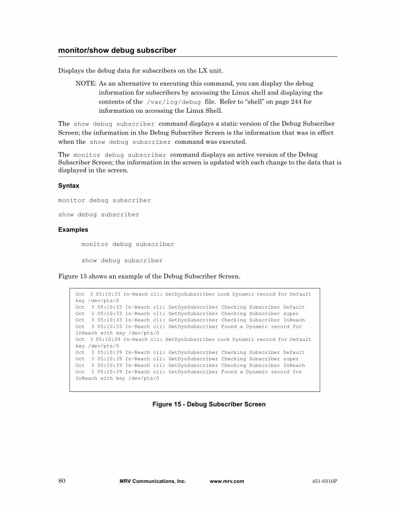
Displays the debug data for subscribers on the LX unit.
NOTE: As an alternative to executing this command, you can display the debug information for subscribers by accessing the Linux shell and displaying the contents of the /var/log/debug file. Refer to “shell” on page 244 for information on accessing the Linux Shell.
The show debug subscriber command displays a static version of the Debug Subscriber Screen; the information in the Debug Subscriber Screen is the information that was in effect when the show debug subscriber command was executed.
The monitor debug subscriber command displays an active version of the Debug Subscriber Screen; the information in the screen is updated with each change to the data that is displayed in the screen.
Syntax
monitor debug subscriber
show debug subscriber
Examples
monitor debug subscriber
show debug subscriber
Figure 15 shows an example of the Debug Subscriber Screen.
Figure 15 - Debug Subscriber Screen
monitor/show debug subscriber
Oct 3 05:10:33 In-Reach cli: GetDynSubscriber Look Dynamic record for Default key /dev/pts/0 Oct 3 05:10:33 In-Reach cli: GetDynSubscriber Checking Subscriber DefaultOct 3 05:10:33 In-Reach cli: GetDynSubscriber Checking Subscriber superOct 3 05:10:33 In-Reach cli: GetDynSubscriber Checking Subscriber InReachOct 3 05:10:33 In-Reach cli: GetDynSubscriber Found a Dynamic record for InReach with key /dev/pts/0 Oct 3 05:10:39 In-Reach cli: GetDynSubscriber Look Dynamic record for Default key /dev/pts/0 Oct 3 05:10:39 In-Reach cli: GetDynSubscriber Checking Subscriber DefaultOct 3 05:10:39 In-Reach cli: GetDynSubscriber Checking Subscriber superOct 3 05:10:39 In-Reach cli: GetDynSubscriber Checking Subscriber InReachOct 3 05:10:39 In-Reach cli: GetDynSubscriber Found a Dynamic record for InReach with key /dev/pts/0
80 MRV Communications, Inc. www.mrv.com 451-0310P

Displays the server-level debug data for the LX unit.
NOTE: As an alternative to executing this command, you can display the server-level debug information by accessing the Linux shell and displaying the contents of the /var/log/debug file. Refer to “shell” on page 244 for information on accessing the Linux Shell.
The show debug system command displays a static version of the System Debug Screen; the information in the System Debug Screen is the information that was in effect when the show debug system command was executed.
The monitor debug system command displays an active version of the System Debug Screen; the information in the screen is updated with each change to the data that is displayed in the screen.
Syntax
monitor debug system
show debug system
Examples
monitor debug system
show debug system
Figure 16 shows an example of the System Debug Screen.
Figure 16 - System Debug Screen
monitor/show debug system
Dec 31 21:13:22 In-Reach syslogd 1.4.1: restart.Dec 31 21:13:23 In-Reach kernel: klogd 1.4.1, log source = /proc/kmsg started.Dec 31 21:13:23 In-Reach kernel: Cannot find map file.Dec 31 21:13:23 In-Reach kernel: No module symbols loaded - kernel modules not enabled.Dec 31 21:13:23 In-Reach kernel: Linux version 2.4.19 (build@GenBuild) (gcc version 3.3) #1 Wed Aug 20 08:13:40 EDT 2003Dec 31 21:13:23 In-Reach kernel: On node 0 totalpages: 16384Dec 31 21:13:23 In-Reach kernel: zone(0): 16384 pages.Dec 31 21:13:23 In-Reach kernel: zone(1): 0 pages.Dec 31 21:13:23 In-Reach kernel: zone(2): 0 pages.Dec 31 21:13:23 In-Reach kernel: Kernel command line: root=/dev/ram CON-SOLE=/dev/consoleDec 31 21:13:23 In-Reach kernel: Decrementer Frequency = 247500000/60Dec 31 21:13:23 In-Reach kernel: Calibrating delay loop... 65.53 BogoMIPS
Type a key to continue, q to quit
451-0310P MRV Communications, Inc. www.mrv.com 81
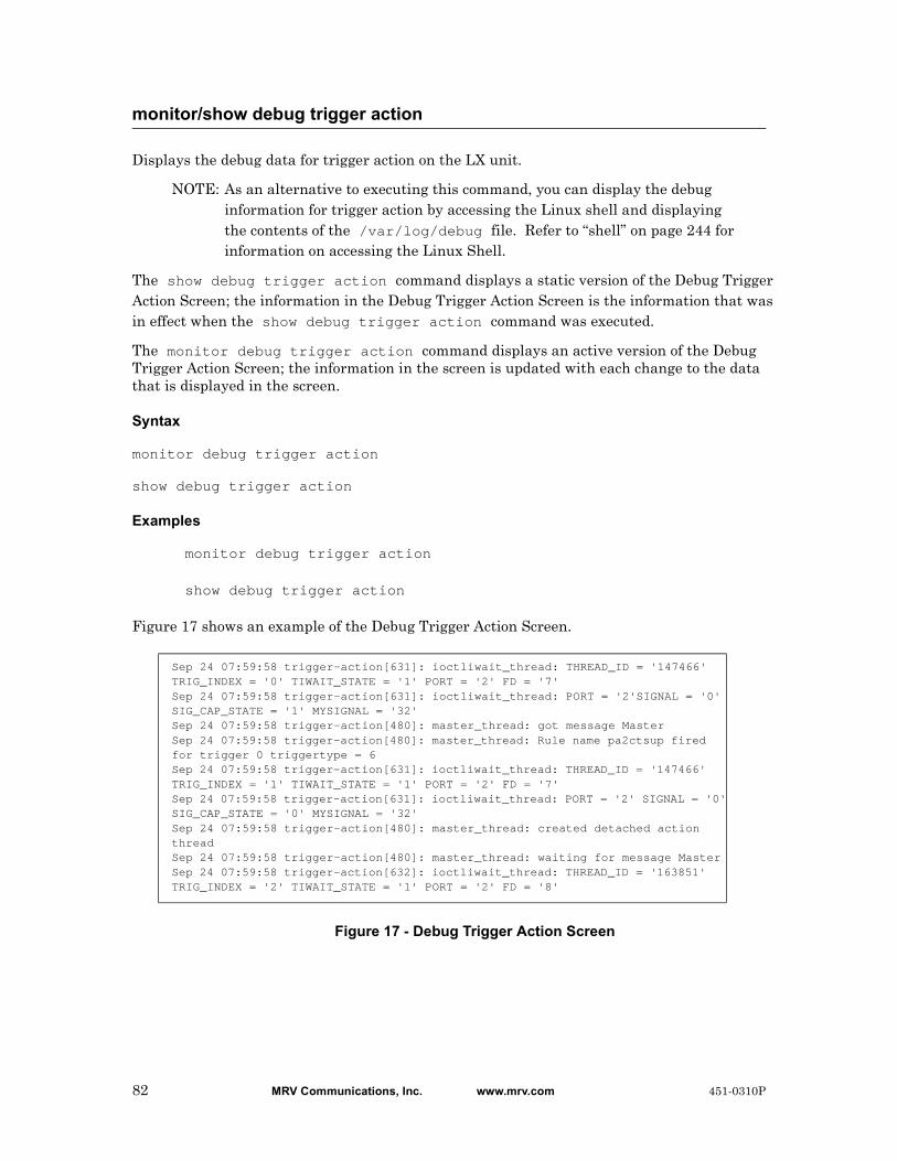
Displays the debug data for trigger action on the LX unit.
NOTE: As an alternative to executing this command, you can display the debug information for trigger action by accessing the Linux shell and displaying the contents of the /var/log/debug file. Refer to “shell” on page 244 for information on accessing the Linux Shell.
The show debug trigger action command displays a static version of the Debug Trigger Action Screen; the information in the Debug Trigger Action Screen is the information that was in effect when the show debug trigger action command was executed.
The monitor debug trigger action command displays an active version of the Debug Trigger Action Screen; the information in the screen is updated with each change to the data that is displayed in the screen.
Syntax
monitor debug trigger action
show debug trigger action
Examples
monitor debug trigger action
show debug trigger action
Figure 17 shows an example of the Debug Trigger Action Screen.
Figure 17 - Debug Trigger Action Screen
monitor/show debug trigger action
Sep 24 07:59:58 trigger-action[631]: ioctliwait_thread: THREAD_ID = '147466' TRIG_INDEX = '0' TIWAIT_STATE = '1' PORT = '2' FD = '7'Sep 24 07:59:58 trigger-action[631]: ioctliwait_thread: PORT = '2'SIGNAL = '0'SIG_CAP_STATE = '1' MYSIGNAL = '32'Sep 24 07:59:58 trigger-action[480]: master_thread: got message MasterSep 24 07:59:58 trigger-action[480]: master_thread: Rule name pa2ctsup fired for trigger 0 triggertype = 6Sep 24 07:59:58 trigger-action[631]: ioctliwait_thread: THREAD_ID = '147466' TRIG_INDEX = '1' TIWAIT_STATE = '1' PORT = '2' FD = '7'Sep 24 07:59:58 trigger-action[631]: ioctliwait_thread: PORT = '2' SIGNAL = '0'SIG_CAP_STATE = '0' MYSIGNAL = '32'Sep 24 07:59:58 trigger-action[480]: master_thread: created detached action threadSep 24 07:59:58 trigger-action[480]: master_thread: waiting for message MasterSep 24 07:59:58 trigger-action[632]: ioctliwait_thread: THREAD_ID = '163851' TRIG_INDEX = '2' TIWAIT_STATE = '1' PORT = '2' FD = '8'
82 MRV Communications, Inc. www.mrv.com 451-0310P
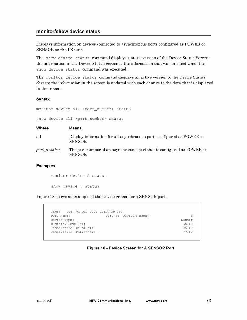
Displays information on devices connected to asynchronous ports configured as POWER or SENSOR on the LX unit.
The show device status command displays a static version of the Device Status Screen; the information in the Device Status Screen is the information that was in effect when the show device status command was executed.
The monitor device status command displays an active version of the Device Status Screen; the information in the screen is updated with each change to the data that is displayed in the screen.
Syntax
monitor device all|<port_number> status
show device all|<port_number> status
Where Means
Examples
monitor device 5 status
show device 5 status
Figure 18 shows an example of the Device Screen for a SENSOR port.
Figure 18 - Device Screen for A SENSOR Port
monitor/show device status
all Display information for all asynchronous ports configured as POWER or SENSOR.
port_number The port number of an asynchronous port that is configured as POWER or SENSOR.
Time: Tue, 01 Jul 2003 21:14:29 UTCPort Name: Port_25 Device Number: 5Device Type: SensorHumidity Level(%): 65.00Temperature (Celsius): 25.00Temperature (Fahrenheit): 77.00
451-0310P MRV Communications, Inc. www.mrv.com 83

Figure 19 shows an example of the Device Screen for a POWER port.
Figure 19 - Device Screen for A POWER Port
monitor/show device status (continued)
Time: 29 Mar 2004 12:24:46 US/EASTERN Device Number: 39 Device Type: IR4800 Model Name: Firmware: Sentry Version 5.3a (Beta 8) Total Outlet Strip Current Load: 1.50 Total Outlet Strip % Current Utilization(%): N/A Outlet Minimum Off Time: 11 Power Boot Sequence: Enabled Power Cli: Disabled Power SCP Authentication: Disabled SCP Admin name: Not configured SCP Admin password: Not configured Power Factory Reset Button: Enabled
Enclosure 1: Status: Normal Input A: Control Status: On Load: N/A Outlet Name State Status Boot Wakeup Load Off 1 IR4800OutletAA1 On On 0 Off 0.0 Amps Enabled Groups: 2,4,5,7,9,11,13,15,17,19,21,23,25,27,29,31,33,35,37,39,41,43,45,47, 49,51,53,55,57,59,61,63,65,67,69,71,73,75,77,79,81,83,85,87,89,91,93,95,97,99 2 IR4800OutletAB1 On On 1 Off 0.5 Amps Enabled Groups: 2,4,6,8,10,12,14,16,18,20,22,24,26,28,30,32,34,36,38,40,42,44,46,48, 50,52,54,56,58,60,62,64,66,68,70,72,74,76,78,80,82,84,86,88,90,92,94,96,98
Input B: Control Status: On Load: N/A Outlet Name State Status Boot Wakeup Load Off 3 IR4800OutletAA2 On On 2 Off 0.5 Amps Enabled Groups: 1,4 4 IR4800OutletAB2 On On 3 Off 0.5 Amps Enabled Groups: 4
84 MRV Communications, Inc. www.mrv.com 451-0310P
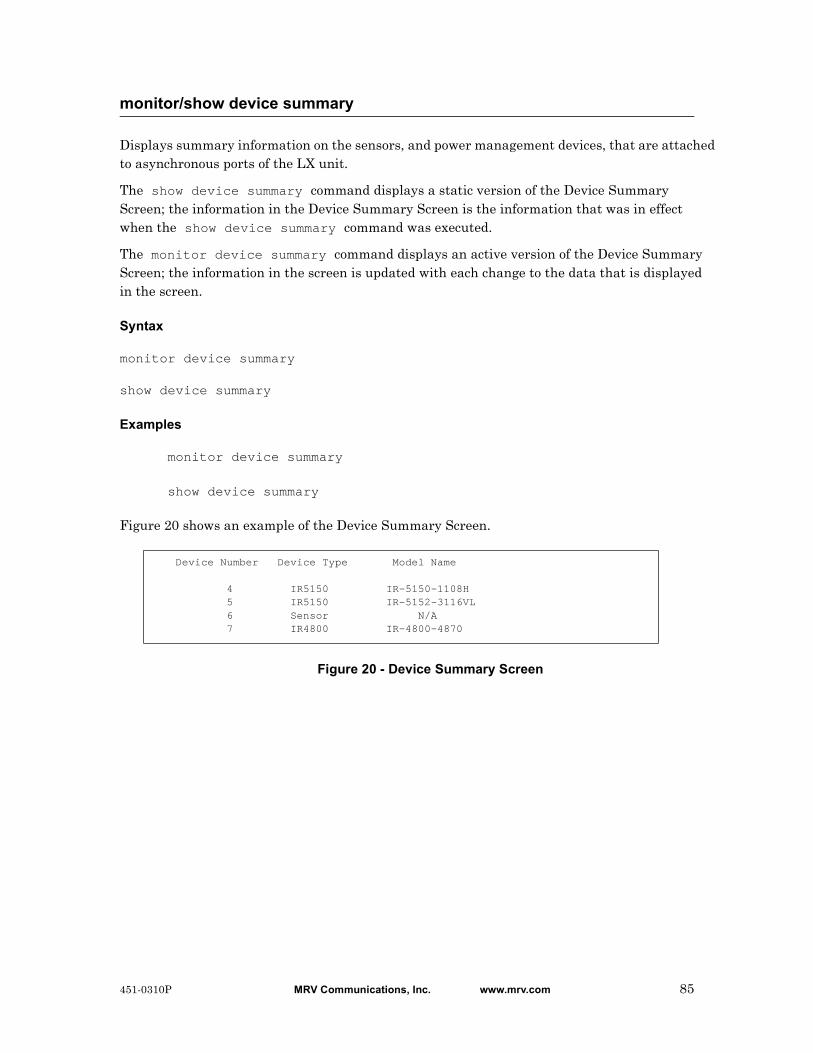
Displays summary information on the sensors, and power management devices, that are attached to asynchronous ports of the LX unit.
The show device summary command displays a static version of the Device Summary Screen; the information in the Device Summary Screen is the information that was in effect when the show device summary command was executed.
The monitor device summary command displays an active version of the Device Summary Screen; the information in the screen is updated with each change to the data that is displayed in the screen.
Syntax
monitor device summary
show device summary
Examples
monitor device summary
show device summary
Figure 20 shows an example of the Device Summary Screen.
Figure 20 - Device Summary Screen
monitor/show device summary
Device Number Device Type Model Name
4 IR5150 IR-5150-1108H 5 IR5150 IR-5152-3116VL 6 Sensor N/A 7 IR4800 IR-4800-4870
451-0310P MRV Communications, Inc. www.mrv.com 85

Displays the characteristics of the named alarm.
The show hdam alarm <alarm_name> characteristics command displays a static version of the HDAM Alarm Name Characteristics Screen; the information in the HDAM Alarm Name Characteristics Screen is the information that was in effect when the show hdam alarm <alarm_name> characteristics command was executed.
The monitor hdam alarm <alarm_name> characteristics command displays an active version of the HDAM Alarm Name Characteristics Screen; the information in the screen is updated with each change to the data that is displayed in the screen.
Syntax
monitor hdam alarm <alarm_name> characteristics
show hdam alarm <alarm_name> characteristics
Examples
monitor hdam alarm 5_4_20 characteristics
show hdam alarm 8_2_5 characteristics
Figure 21 shows an example of the HDAM Alarm Name Characteristics Screen.
Figure 21 - HDAM Alarm Name Characteristics Screen
monitor/show hdam alarm name characteristics
Fault Debounce Trap TrapPort Slot Point Name Audible State Interval Setting Severity 1 2 5 8_2_5 Disabled Open 3 Enabled Minor
Description:
Field Description
Port The current port number.
Slot The current slot number.
Point The current point.
Name The point name.
Audible Indicates whether the Audible alarm is Enabled or Disabled.
Fault State Indicates whether the Fault State is Open or Closed.
Debounce Interval
Indicates the Debounce Interval, in seconds.
86 MRV Communications, Inc. www.mrv.com 451-0310P

monitor/show hdam alarm name characteristics (continued)
Trap Setting Indicates the SNMP Trap Setting (Enabled or Disabled).
Trap Severity Indicates the SNMP Trap Severity level. The options are Critical, Information, Major, Minor, and Warning.
Description The configured alarm description.
451-0310P MRV Communications, Inc. www.mrv.com 87

Displays the status of the named alarm.
The show hdam alarm <alarm_name> status command displays a static version of the HDAM Alarm Name Status Screen; the information in the HDAM Alarm Name Status Screen is the information that was in effect when the show hdam alarm <alarm_name> status command was executed.
The monitor hdam alarm <alarm_name> status command displays an active version of the HDAM Alarm Name Status Screen; the information in the screen is updated with each change to the data that is displayed in the screen.
Syntax
monitor hdam alarm <alarm_name> status
show hdam alarm <alarm_name> status
Examples
monitor hdam alarm 5_4_20 status
show hdam alarm 8_2_5 status
Figure 22 shows an example of the HDAM Alarm Name Status Screen.
Figure 22 - HDAM Alarm Name Status Screen
monitor/show hdam alarm name status
Current Fired Last Time Port Slot Point Name State Count Fired 1 2 5 8_2_5 Faulted 5 Wed,20 Oct 2004 11:47:24 UTC
Field Description
Port The current port number.
Slot The current slot number.
Point The current point.
Name The point name.
Current State The Current State of the alarm (Faulted or Normal).
Fired Count Indicates the number of times the alarm has tripped.
Last Time Fired Indicates the last time the alarm was tripped.
88 MRV Communications, Inc. www.mrv.com 451-0310P
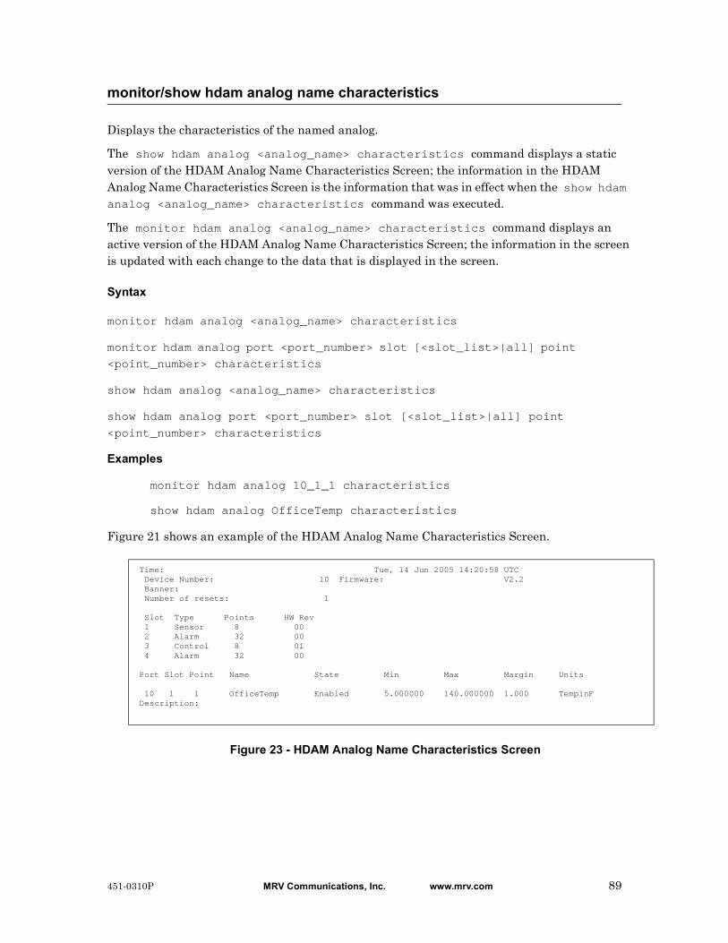
Displays the characteristics of the named analog.
The show hdam analog <analog_name> characteristics command displays a static version of the HDAM Analog Name Characteristics Screen; the information in the HDAM Analog Name Characteristics Screen is the information that was in effect when the show hdam analog <analog_name> characteristics command was executed.
The monitor hdam analog <analog_name> characteristics command displays an active version of the HDAM Analog Name Characteristics Screen; the information in the screen is updated with each change to the data that is displayed in the screen.
Syntax
monitor hdam analog <analog_name> characteristics
monitor hdam analog port <port_number> slot [<slot_list>|all] point
<point_number> characteristics
show hdam analog <analog_name> characteristics
show hdam analog port <port_number> slot [<slot_list>|all] point
<point_number> characteristics
Examples
monitor hdam analog 10_1_1 characteristics
show hdam analog OfficeTemp characteristics
Figure 21 shows an example of the HDAM Analog Name Characteristics Screen.
Figure 23 - HDAM Analog Name Characteristics Screen
monitor/show hdam analog name characteristics
Time: Tue, 14 Jun 2005 14:20:58 UTC Device Number: 10 Firmware: V2.2 Banner: Number of resets: 1 Slot Type Points HW Rev 1 Sensor 8 00 2 Alarm 32 00 3 Control 8 01 4 Alarm 32 00 Port Slot Point Name State Min Max Margin Units 10 1 1 OfficeTemp Enabled 5.000000 140.000000 1.000 TempinFDescription:
451-0310P MRV Communications, Inc. www.mrv.com 89
monitor/show hdam analog name characteristics (continued)
Field Description
Device Number The current device number.
Firmware The current firmware version.
Banner The banner identifying the current device.
Number of Resets
The number of times the device has been reset.
Slot The current slot number.
Type The type of port. Options are Sensor, Alarm, and Control.
Point The current point.
Name The point name.
State Indicates whether the State is Enabled or Disabled.
Minimum Indicates the minimum calibration level.
Maximum Indicates the maximum calibration level.
Margin Indicates the margin value.
Units Identifies the native units of the sensor.
90 MRV Communications, Inc. www.mrv.com 451-0310P

Displays the status of the named analog point.
The show hdam analog <analog_name> status command displays a static version of the HDAM Analog Name Status Screen; the information in the HDAM Analog Name Status Screen is the information that was in effect when the show hdam analog <analog_name> status command was executed.
The monitor hdam analog <analog_name> status command displays an active version of the HDAM Analog Name Status Screen; the information in the screen is updated with each change to the data that is displayed in the screen.
Syntax
monitor hdam analog <analog_name> status
monitor hdam analog port <port_number> slot <slot_number> point
<point_number> status
show hdam analog <analog_name> status
show hdam analog port <port_number> slot <slot_number> point
<point_number> status
Examples
monitor hdam analog 5_4_8 status
show hdam analog BarometricPressureInMyOffice status
Figure 22 shows an example of the HDAM Analog Name Status Screen.
Figure 24 - HDAM Analog Name Status Screen
monitor/show hdam analog name status
Time: Tue, 14 Jun 2005 14:21:05 UTCDevice Number: 10 Temperature (Celsius): 27.0 Port Slot Point Name Native Units Value MilliAmp Value 10 1 6 BarometricPressureInMyOffice 29.712820 Hg 16.732601 mA
Field Description
Device Number The number of the current device.
Temperature The temperature of the temperature sensor internal to the 7104 attached to this port.
Port The current port number.
Slot The current slot number.
Point The current point.
451-0310P MRV Communications, Inc. www.mrv.com 91

monitor/show hdam analog name status (continued)
Name The point name.
Native Units Value
The current reading of the attached sensor in its native units.
MilliAmp Value The current reading of the attached sensor in milliamps.
92 MRV Communications, Inc. www.mrv.com 451-0310P
Displays general characteristics information for the HDAM connected to the port.
The show hdam <port_number> characteristics command displays a static version of the HDAM Port Characteristics Screen; the information in the HDAM Port Characteristics Screen is the information that was in effect when the show hdam <port_number> characteristics command was executed.
The monitor hdam <port_number> characteristics command displays an active version of the HDAM Port Characteristics Screen; the information in the screen is updated with each change to the data that is displayed in the screen.
Syntax
monitor hdam <port_number> characteristics
show hdam <port_number> characteristics
Examples
monitor hdam 4 characteristics
show hdam 8 characteristics
monitor/show hdam characteristics
451-0310P MRV Communications, Inc. www.mrv.com 93
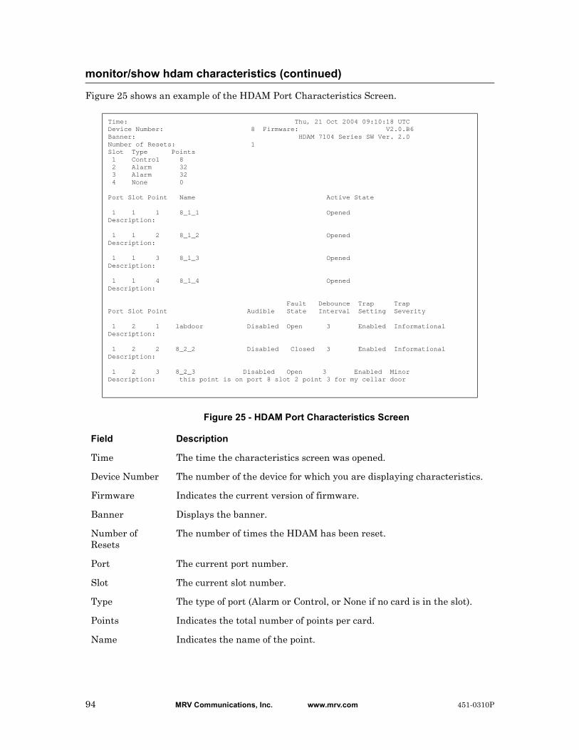
Figure 25 shows an example of the HDAM Port Characteristics Screen.
Figure 25 - HDAM Port Characteristics Screen
monitor/show hdam characteristics (continued)
Time: Thu, 21 Oct 2004 09:10:18 UTCDevice Number: 8 Firmware: V2.0.B6Banner: HDAM 7104 Series SW Ver. 2.0Number of Resets: 1Slot Type Points 1 Control 8 2 Alarm 32 3 Alarm 32 4 None 0 Port Slot Point Name Active State 1 1 1 8_1_1 OpenedDescription: 1 1 2 8_1_2 OpenedDescription: 1 1 3 8_1_3 OpenedDescription: 1 1 4 8_1_4 OpenedDescription: Fault Debounce Trap TrapPort Slot Point Audible State Interval Setting Severity 1 2 1 labdoor Disabled Open 3 Enabled InformationalDescription: 1 2 2 8_2_2 Disabled Closed 3 Enabled InformationalDescription: 1 2 3 8_2_3 Disabled Open 3 Enabled MinorDescription: this point is on port 8 slot 2 point 3 for my cellar door
Field Description
Time The time the characteristics screen was opened.
Device Number The number of the device for which you are displaying characteristics.
Firmware Indicates the current version of firmware.
Banner Displays the banner.
Number of Resets
The number of times the HDAM has been reset.
Port The current port number.
Slot The current slot number.
Type The type of port (Alarm or Control, or None if no card is in the slot).
Points Indicates the total number of points per card.
Name Indicates the name of the point.
94 MRV Communications, Inc. www.mrv.com 451-0310P
monitor/show hdam characteristics (continued)
Description The configured alarm description.
Audible Indicates whether the audible alarm is Enabled or Disabled.
Fault State Indicates whether the fault state is Open or Closed.
Debounce Interval
Indicates the Debounce Interval, in seconds.
Trap Setting Indicated whether the SNMP trap setting is Enabled or Disabled.
Trap Severity Indicates the SNMP Trap Severity level. The options are Critical, Information, Major, Minor, and Warning.
451-0310P MRV Communications, Inc. www.mrv.com 95
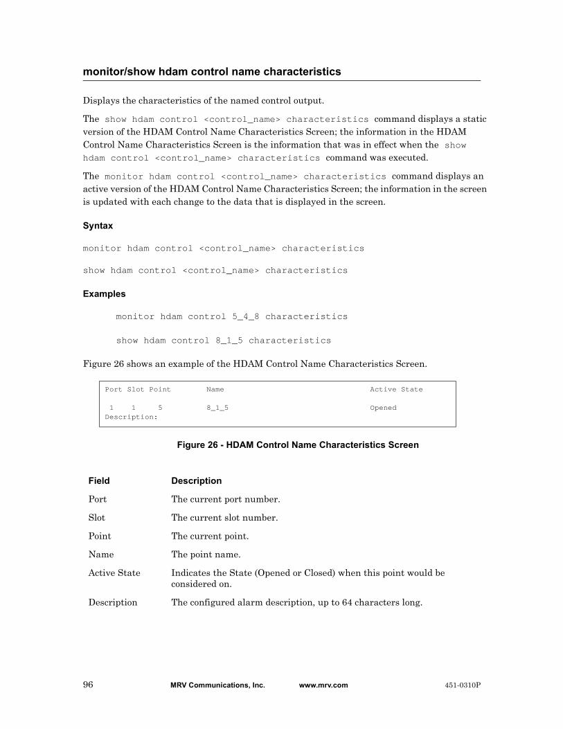
Displays the characteristics of the named control output.
The show hdam control <control_name> characteristics command displays a static version of the HDAM Control Name Characteristics Screen; the information in the HDAM Control Name Characteristics Screen is the information that was in effect when the show hdam control <control_name> characteristics command was executed.
The monitor hdam control <control_name> characteristics command displays an active version of the HDAM Control Name Characteristics Screen; the information in the screen is updated with each change to the data that is displayed in the screen.
Syntax
monitor hdam control <control_name> characteristics
show hdam control <control_name> characteristics
Examples
monitor hdam control 5_4_8 characteristics
show hdam control 8_1_5 characteristics
Figure 26 shows an example of the HDAM Control Name Characteristics Screen.
Figure 26 - HDAM Control Name Characteristics Screen
monitor/show hdam control name characteristics
Port Slot Point Name Active State 1 1 5 8_1_5 OpenedDescription:
Field Description
Port The current port number.
Slot The current slot number.
Point The current point.
Name The point name.
Active State Indicates the State (Opened or Closed) when this point would be considered on.
Description The configured alarm description, up to 64 characters long.
96 MRV Communications, Inc. www.mrv.com 451-0310P

Displays the status of the named control output.
The show hdam control <control_name> status command displays a static version of the HDAM Control Name Status Screen; the information in the HDAM Control Name Status Screen is the information that was in effect when the show hdam control <control_name> status command was executed.
The monitor hdam control <control_name> status command displays an active version of the HDAM Control Name Status Screen; the information in the screen is updated with each change to the data that is displayed in the screen.
Syntax
monitor hdam control <control_name> status
show hdam control <control_name> status
Examples
monitor hdam control 5_4_8 status
show hdam control 8_1_5 status
Figure 27 shows an example of the HDAM Control Name Status Screen.
Figure 27 - HDAM Control Name Status Screen
monitor/show hdam control name status
Current Operational Port Slot Point Name State State 1 1 5 8_1_5 Opened On
Field Description
Port The current port number.
Slot The current slot number.
Point The current point.
Name The point name.
Current State Indicates whether the contact is actually open or closed.
Operational State
Indicates the Operational State (On or Off), as determined by comparing the configured Active State of the point to the Current State of the point. If the Active State matches the Current State, the point is considered “On.”
451-0310P MRV Communications, Inc. www.mrv.com 97

Displays the mapping between point numbers and their names. If you specify all, all mappings are shown.
The show hdam mapping <point_name> | all command displays a static version of the HDAM Mapping Screen; the information in the HDAM Mapping Screen is the information that was in effect when the show hdam mapping <point_name> | all command was executed.
The monitor hdam mapping <point_name> | all command displays an active version of the HDAM Mapping Screen; the information in the screen is updated with each change to the data that is displayed in the screen.
Syntax
monitor hdam mapping <point_name> | all
show hdam mapping <point_name> | all
Examples
monitor hdam mapping 5_4_20
monitor hdam mapping all
show hdam mapping 5_2_31
show hdam mapping all
Figure 28 shows an example of the HDAM Mapping Screen.
Figure 28 - HDAM Mapping Screen
monitor/show hdam mapping
Name Port Slot Point
8_1_1 8 1 1 8_1_2 8 1 2 8_1_3 8 1 3 8_1_4 8 1 4 8_1_5 8 1 5 8_1_6 8 1 6 8_1_7 8 1 7 8_1_8 8 1 8 8_2_1 8 2 1 8_2_2 8 2 2 8_2_3 8 2 3 8_2_4 8 2 4 8_2_5 8 2 5 8_2_6 8 2 6 8_2_7 8 2 7 8_2_8 8 2 8
98 MRV Communications, Inc. www.mrv.com 451-0310P
monitor/show hdam mapping (continued)
Name The name of the port for which you are displaying mapping.
Port The Port number for which you are displaying mapping.
Slot The Slot number for which you are displaying mapping.
Point The Point number for which you are displaying mapping.
451-0310P MRV Communications, Inc. www.mrv.com 99

Displays the port/slot/point characteristics of the named alarm.
The show hdam <port_number> slot <slot_list> point <point_list> characteristics command displays a static version of the HDAM Port/Slot/Point Characteristics Screen; the information in the HDAM Port/Slot/Point Characteristics Screen is the information that was in effect when the show hdam <port_number> slot <slot_list> point <point_list> characteristics command was executed.
The monitor hdam <port_number> slot <slot_list> point <point_list> characteristics command displays an active version of the HDAM Port/Slot/Point Characteristics Screen; the information in the screen is updated with each change to the data that is displayed in the screen.
Syntax
monitor hdam <port_number> slot <slot_list>|all point
<point_list>|all characteristics
show hdam <port_number> slot <slot_list>|all point <point_list>|all
characteristics
Examples
monitor hdam 6 slot 1 point 1-3 characteristics
show hdam 6 slot 6 point 12 characteristics
show hdam 8 slot all point 1-10, 12 characteristics
Figure 29 shows an example of the HDAM Port/Slot/Point Characteristics Screen if Slot 1 contains a Control card.
Figure 29 - HDAM Port/Slot/Point Characteristics Control Card Screen
monitor/show hdam port/slot/point characteristics
Port Slot Point Name Active State 1 1 1 8_1_1 OpenedDescription: 1 1 2 8_1_2 OpenedDescription: 1 1 3 8_1_3 OpenedDescription:
1 1 4 8_1_4 OpenedDescription: 1 1 5 8_1_5 OpenedDescription: 1 1 6 8_1_6 OpenedDescription:
100 MRV Communications, Inc. www.mrv.com 451-0310P

Figure 30 shows an example of the HDAM Port/Slot/Point Characteristics Screen if Slot 1 contains an Alarm card.
Figure 30 - HDAM Port/Slot/Point Characteristics Alarm Card Screen
monitor/show hdam port/slot/point characteristics (continued)
Field Description
Port The current port number.
Slot The current slot number.
Point The current point.
Name The point name.
Active State Indicates the State (Opened or Closed) when this point would be considered on.
Description The configured alarm control.
Fault Debounce Trap TrapPort Slot Point Name Audible State Interval Setting Severity 1 2 3 8_2_3 Disabled Open 3 Enabled MinorDescription: this point is on port 8 slot 2 point 3 for my cellar door 1 2 4 8_2_4 Disabled Open 3 Enabled MinorDescription: 1 2 5 8_2_5 Disabled Open 3 Enabled MinorDescription: 1 2 6 8_2_6 Disabled Open 3 Enabled MinorDescription: 1 2 7 8_2_7 Disabled Open 3 Enabled MinorDescription:
Field Description
Port The current port number.
Slot The current slot number.
Point The current point.
Name The point name.
Fault State Indicates the state when this point is considered in Fault.
Audible Indicates whether the Audible alarm is Enabled or Disabled.
Debounce Interval Indicates the Debounce Interval, in seconds.
451-0310P MRV Communications, Inc. www.mrv.com 101
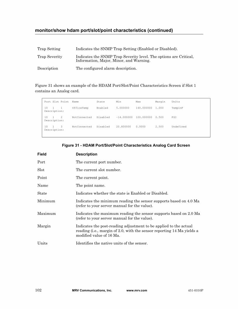
Figure 31 shows an example of the HDAM Port/Slot/Point Characteristics Screen if Slot 1 contains an Analog card.
Figure 31 - HDAM Port/Slot/Point Characteristics Analog Card Screen
monitor/show hdam port/slot/point characteristics (continued)
Trap Setting Indicates the SNMP Trap Setting (Enabled or Disabled).
Trap Severity Indicates the SNMP Trap Severity level. The options are Critical, Information, Major, Minor, and Warning.
Description The configured alarm description.
Port Slot Point Name State Min Max Margin Units 10 1 1 OfficeTemp Enabled 5.000000 140.000000 1.000 TempinFDescription: 10 1 2 NotConnected Disabled -14.000000 100.000000 0.500 PSIDescription: 10 1 3 NotConnected Disabled 20.800000 0.0000 2.500 UndefinedDescription:
Field Description
Port The current port number.
Slot The current slot number.
Point The current point.
Name The point name.
State Indicates whether the state is Enabled or Disabled.
Minimum Indicates the minimum reading the sensor supports based on 4.0 Ma (refer to your server manual for the value).
Maximum Indicates the maximum reading the sensor supports based on 2.0 Ma (refer to your server manual for the value).
Margin Indicates the post-reading adjustment to be applied to the actual reading (i.e., margin of 2.0, with the sensor reporting 14 Ma yields a modified value of 16 Ma.
Units Identifies the native units of the sensor.
102 MRV Communications, Inc. www.mrv.com 451-0310P

Displays the port/slot/point status of the named alarm.
The show hdam <port_number> slot <slot_list> point <point_list> status command displays a static version of the HDAM Port/Slot/Point Status Screen; the information in the HDAM Port/Slot/Point Status Screen is the information that was in effect when the show hdam <port_number> slot <slot_list> point <point_list> status command was executed.
The monitor hdam <port_number> slot <slot_list> point <point_list> status command displays an active version of the HDAM Port/Slot/Point Status Screen; the information in the screen is updated with each change to the data that is displayed in the screen.
Syntax
monitor hdam <port_number> slot <slot_list>|all point
<point_list>|all status
show hdam <port_number> slot <slot_list>|all point <point_list>|all
status
Examples
monitor hdam 6 slot 1 point 1-3 status
show hdam 6 slot 4 point 8 status
show hdam 6 slot 1 point all status
Figure 32 shows an example of the HDAM Port/Slot/Point Status Screen if Slot 1 contains a Control card.
Figure 32 - HDAM Port/Slot/Point Status Control Card Screen
monitor/show hdam port/slot/point status
Current Operational Port Slot Point Name State State 1 1 1 8_1_1 Opened On 1 1 2 8_1_2 Opened On 1 1 3 8_1_3 Opened On 1 1 4 8_1_4 Opened On 1 1 5 8_1_5 Opened On 1 1 6 8_1_6 Opened On 1 1 7 8_1_7 Opened On 1 1 8 8_1_8 Opened On
451-0310P MRV Communications, Inc. www.mrv.com 103
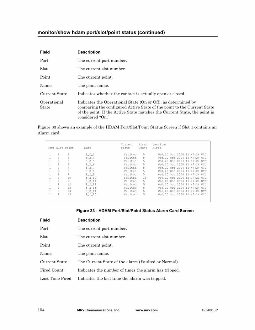
Figure 33 shows an example of the HDAM Port/Slot/Point Status Screen if Slot 1 contains an Alarm card.
Figure 33 - HDAM Port/Slot/Point Status Alarm Card Screen
monitor/show hdam port/slot/point status (continued)
Field Description
Port The current port number.
Slot The current slot number.
Point The current point.
Name The point name.
Current State Indicates whether the contact is actually open or closed.
Operational State
Indicates the Operational State (On or Off), as determined by comparing the configured Active State of the point to the Current State of the point. If the Active State matches the Current State, the point is considered “On.”
Current Fired LastTimePort Slot Point Name State Count Fired 1 2 3 8_2_3 Faulted 5 Wed,20 Oct 2004 11:47:24 UTC 1 2 4 8_2_4 Faulted 5 Wed,20 Oct 2004 11:47:24 UTC 1 2 5 8_2_5 Faulted 5 Wed,20 Oct 2004 11:47:24 UTC 1 2 6 8_2_6 Faulted 5 Wed,20 Oct 2004 11:47:24 UTC 1 2 7 8_2_7 Faulted 5 Wed,20 Oct 2004 11:47:24 UTC 1 2 8 8_2_8 Faulted 5 Wed,20 Oct 2004 11:47:24 UTC 1 2 9 8_2_9 Faulted 5 Wed,20 Oct 2004 11:47:24 UTC 1 2 10 8_2_10 Faulted 13 Wed,20 Oct 2004 12:17:21 UTC 1 2 11 8_2_11 Faulted 5 Wed,20 Oct 2004 11:47:24 UTC 1 2 12 8_2_12 Faulted 5 Wed,20 Oct 2004 11:47:24 UTC 1 2 13 8_2_13 Faulted 5 Wed,20 Oct 2004 11:47:24 UTC 1 2 14 8_2_14 Faulted 5 Wed,20 Oct 2004 11:47:24 UTC 1 2 15 8_2_15 Faulted 5 Wed,20 Oct 2004 11:47:24 UTC
Field Description
Port The current port number.
Slot The current slot number.
Point The current point.
Name The point name.
Current State The Current State of the alarm (Faulted or Normal).
Fired Count Indicates the number of times the alarm has tripped.
Last Time Fired Indicates the last time the alarm was tripped.
104 MRV Communications, Inc. www.mrv.com 451-0310P

Figure 34 shows an example of the HDAM Port/Slot/Point Status Screen if Slot 1 contains an
Analog card.
Figure 34 - HDAM Port/Slot/Point Status Analog Card Screen
monitor/show hdam port/slot/point status (continued)
Port Slot Point Name Native Units Value MilliAmp Value 10 1 1 Officetemp N/A 0.000000 mA 10 1 2 NothingConnectedToPoint2 N/ A N/A 10 1 3 NothingConnectedToPoint3 N/A N/A 10 1 4 NothingConnectedToPoint4 N/A N/A 10 1 5 NothingThere N/A 0.019536 mA 10 1 6 BarometricPressureInMyOffice 29.712820 Hg 16.732601 mA 10 1 7 HumidityInMyOfficeWithEWSRH 43.131866 %R 10.778998 mA 10 1 8 TemperatureInMyOfficeWithEWSRH 83.420326 TempinF 13.294261 mA
Field Description
Port The current port number.
Slot The current slot number.
Point The current point.
Name The point name.
Native Units Value
The current reading of the attached sensor in its native units.
MilliAmp Value The current reading of the attached sensor in milliamps.
451-0310P MRV Communications, Inc. www.mrv.com 105
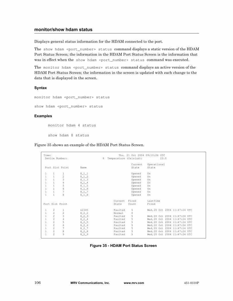
Displays general status information for the HDAM connected to the port.
The show hdam <port_number> status command displays a static version of the HDAM Port Status Screen; the information in the HDAM Port Status Screen is the information that was in effect when the show hdam <port_number> status command was executed.
The monitor hdam <port_number> status command displays an active version of the HDAM Port Status Screen; the information in the screen is updated with each change to the data that is displayed in the screen.
Syntax
monitor hdam <port_number> status
show hdam <port_number> status
Examples
monitor hdam 4 status
show hdam 8 status
Figure 35 shows an example of the HDAM Port Status Screen.
Figure 35 - HDAM Port Status Screen
monitor/show hdam status
Time: Thu, 21 Oct 2004 09:10:06 UTC Device Number: 8 Temperature (Celsius): 23.0 Current Operational Port Slot Point Name State State 1 1 1 8_1_1 Opened On 1 1 2 8_1_2 Opened On 1 1 3 8_1_3 Opened On 1 1 4 8_1_4 Opened On 1 1 5 8_1_5 Opened On 1 1 6 8_1_6 Opened On 1 1 7 8_1_7 Opened On 1 1 8 8_1_8 Opened On Current Fired LastTimePort Slot Point State Count Fired 1 2 1 n2345 Faulted 5 Wed,20 Oct 2004 11:47:24 UTC 1 2 2 8_2_2 Normal 0 1 2 3 8_2_3 Faulted 5 Wed,20 Oct 2004 11:47:24 UTC 1 2 4 8_2_4 Faulted 5 Wed,20 Oct 2004 11:47:24 UTC 1 2 5 8_2_5 Faulted 5 Wed,20 Oct 2004 11:47:24 UTC 1 2 6 8_2_6 Faulted 5 Wed,20 Oct 2004 11:47:24 UTC 1 2 7 8_2_7 Faulted 5 Wed,20 Oct 2004 11:47:24 UTC 1 2 8 8_2_8 Faulted 5 Wed,20 Oct 2004 11:47:24 UTC 1 2 9 8_2_9 Faulted 5 Wed,20 Oct 2004 11:47:24 UTC
106 MRV Communications, Inc. www.mrv.com 451-0310P

monitor/show hdam status (continued)
Device Number The name of the device for which you are displaying status.
Temperature (Celsius)
The temperature (in Celsius) of the device.
Port The current port number.
Slot The current slot number.
Point The current point.
Name The point name.
Current State The Current State of the alarm (Faulted or Normal).
Operational State
Indicates the Operational State (On or Off), as determined by comparing the configured Active State of the point to the Current State of the point. If the Active State matches the Current State, the point is considered “On.”
Fired Count The number of times the alarm input has tripped.
Last Time Fired Indicates the last time the alarm input was tripped.
451-0310P MRV Communications, Inc. www.mrv.com 107
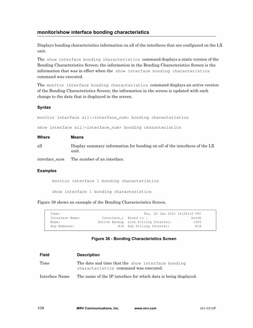
Displays bonding characteristics information on all of the interfaces that are configured on the LX unit.
The show interface bonding characteristics command displays a static version of the Bonding Characteristics Screen; the information in the Bonding Characteristics Screen is the information that was in effect when the show interface bonding characteristics command was executed.
The monitor interface bonding characteristics command displays an active version of the Bonding Characteristics Screen; the information in the screen is updated with each change to the data that is displayed in the screen.
Syntax
monitor interface all|<interface_num> bonding characteristics
show interface all|<interface_num> bonding characteristics
Where Means
Examples
monitor interface 1 bonding characteristics
show interface 1 bonding characteristics
Figure 39 shows an example of the Bonding Characteristics Screen.
Figure 36 - Bonding Characteristics Screen
monitor/show interface bonding characteristics
all Display summary information for bonding on all of the interfaces of the LX unit.
interface_num The number of an interface.
Time: Thu, 20 Jan 2005 14:28:10 UTC Interface Name: Interface_1 Bound to : bond0 Mode: Active Backup Link Polling Interval: 1000 Arp Address: N/A Arp Polling Interval: N/A
Field Description
Time The date and time that the show interface bonding characteristics command was executed.
Interface Name The name of the IP interface for which data is being displayed.
108 MRV Communications, Inc. www.mrv.com 451-0310P

monitor/show interface bonding characteristics (continued)
Mode Defined as “Active Backup” when a backup link is configured.
ARP Address The ARP address of the link.
Bound To The logical bond that was created (bond0).
Link Polling Interval
The Link Polling Interval, in milliseconds.
ARP Polling Interval
The ARP Polling Interval, in milliseconds.
451-0310P MRV Communications, Inc. www.mrv.com 109
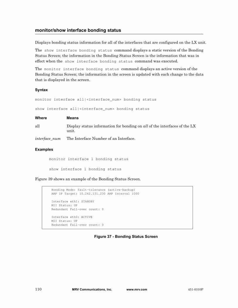
Displays bonding status information for all of the interfaces that are configured on the LX unit.
The show interface bonding status command displays a static version of the Bonding Status Screen; the information in the Bonding Status Screen is the information that was in effect when the show interface bonding status command was executed.
The monitor interface bonding status command displays an active version of the Bonding Status Screen; the information in the screen is updated with each change to the data that is displayed in the screen.
Syntax
monitor interface all|<interface_num> bonding status
show interface all|<interface_num> bonding status
Where Means
Examples
monitor interface 1 bonding status
show interface 1 bonding status
Figure 39 shows an example of the Bonding Status Screen.
Figure 37 - Bonding Status Screen
monitor/show interface bonding status
all Display status information for bonding on all of the interfaces of the LX unit.
interface_num The Interface Number of an Interface.
Bonding Mode: fault-tolerance (active-backup)ARP IP Target: 10.242.131.230 ARP Interval 1000
Interface eth1: STANDBYMII Status: UPRedundant Fail-over count: 0
Interface eth0: ACTIVEMII Status: UPRedundant Fail-over count: 0
110 MRV Communications, Inc. www.mrv.com 451-0310P

monitor/show interface bonding status (continued)
Field Description
Bonding Mode Defined as “Active Backup” when a backup link is configured.
ARP IP Target The name of the current ARP IP Target.
Interface eth1 The status of the interface. Options are Standby Active or Down.
MII Status The status of the physical link. Options are Up or Down.
Redundant Fail-over Count
The number of times the link went from Active to Standby or Down.
451-0310P MRV Communications, Inc. www.mrv.com 111
Displays the characteristics of Broadcast Groups.
The show interface broadcast group characteristics command displays a static version of the Broadcast Group Characteristics Screen; the information in the Broadcast Group Characteristics Screen is the information that was in effect when the show interface broadcast group characteristics command was executed.
The monitor interface broadcast group characteristics command displays an active version of the Broadcast Group Characteristics Screen; the information in the screen is updated with each change to the data that is displayed in the screen.
Syntax
monitor interface all|<interface_num> broadcast group all|<group_num>
characteristics
show interface all|<interface_num> broadcast group all|<group_num>
characteristics
Where Means
Examples
monitor interface 1 broadcast group all characteristics
show interface 1 broadcast group all characteristics
monitor/show interface broadcast group characteristics
all Display information for all of the specified interfaces or all of the specified Broadcast Groups. For example, the following command would display information for all Broadcast Groups on all interfaces of the LX unit:
show interface all broadcast group all characteristics
The following command would display information for all Broadcast Groups on Interface 1:
show interface 1 broadcast group all characteristics
The following command would display information for Broadcast Group 1 on all interfaces:
show interface all broadcast group 1 characteristics
interface_num The Interface Number of an Interface.
group_num The group number of a Broadcast Group.
112 MRV Communications, Inc. www.mrv.com 451-0310P
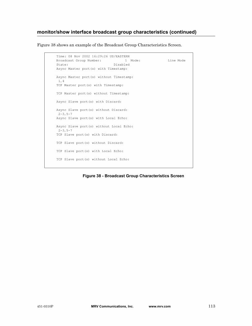
Figure 38 shows an example of the Broadcast Group Characteristics Screen.
Figure 38 - Broadcast Group Characteristics Screen
monitor/show interface broadcast group characteristics (continued)
Time: 08 Nov 2002 16:29:26 US/EASTERN Broadcast Group Number: 1 Mode: Line Mode State: Disabled Async Master port(s) with Timestamp:
Async Master port(s) without Timestamp: 1,4 TCP Master port(s) with Timestamp:
TCP Master port(s) without Timestamp:
Async Slave port(s) with Discard:
Async Slave port(s) without Discard: 2-3,5-7 Async Slave port(s) with Local Echo:
Async Slave port(s) without Local Echo: 2-3,5-7 TCP Slave port(s) with Discard:
TCP Slave port(s) without Discard:
TCP Slave port(s) with Local Echo:
TCP Slave port(s) without Local Echo:
451-0310P MRV Communications, Inc. www.mrv.com 113

Displays summary information on all of the Broadcast Groups that are configured on the LX unit.
The show interface broadcast group summary command displays a static version of the Broadcast Group Summary Screen; the information in the Broadcast Group Summary Screen is the information that was in effect when the show interface broadcast group summary command was executed.
The monitor interface broadcast group summary command displays an active version of the Broadcast Group Summary Screen; the information in the screen is updated with each change to the data that is displayed in the screen.
Syntax
monitor interface all|<interface_num> broadcast group summary
show interface all|<interface_num> broadcast group summary
Where Means
Examples
monitor interface 1 broadcast group summary
show interface 1 broadcast group summary
Figure 39 shows an example of the Broadcast Group Summary Screen.
Figure 39 - Broadcast Group Summary Screen
monitor/show interface broadcast group summary
all Display summary information for the Broadcast Group on all of the interfaces of the LX unit.
interface_num The Interface Number of an Interface.
Interface number 1 Broadcast group number: State:
1 Enabled 2 Disabled 3 Disabled 4 Disabled 5 Disabled
114 MRV Communications, Inc. www.mrv.com 451-0310P

Displays the characteristics of an IP interface.
The show interface characteristics command displays a static version of the Interface Characteristics Screen; the information in the Interface Characteristics Screen is the information that was in effect when the show interface characteristics command was executed.
The monitor interface characteristics command displays an active version of the Interface Characteristics Screen; the information in the screen is updated with each change to the data that is displayed in the screen.
Syntax
monitor interface NUMBER|all characteristics
show interface NUMBER|all characteristics
Where Means
Examples
monitor interface 1 characteristics
show interface 1 characteristics
Figure 40 shows an example of the Interface Characteristics Screen.
Figure 40 - Interface Characteristics Screen
monitor/show interface characteristics
NUMBER Specifies the IP interface for which information is to be displayed.
all Display information for all the IP interfaces on the LX unit.
Time: Wed, 05 Jan 2005 11:40:11 US/EASTERN Interface Name: Interface_1 Bound to : eth0 IP MTU Size: N/A Unnumbered Interface: First Available IP Address : 0.0.0.0 Learned IP Address : 140.179.169.191 IP Mask : 0.0.0.0 Learned IP Mask : 255.255.255.0 IP Broadcast : 0.0.0.0 Learned IP Broadcast: 140.179.169.255 Interface Status: In Use Learned IP Gateway : 140.179.169.1 Banner Display: Local Learned IP DNS : 0.0.0.0 Banner: /config/banner.default Radius Accounting: Disabled Authentication: None Tacacs+ Accounting: Disabled Authentication FallBack: Disabled Auth. FallBack Attempts: 0 SSH port: 22 Telnet port: 23
451-0310P MRV Communications, Inc. www.mrv.com 115

monitor/show interface characteristics (continued)
Field Description
Time The date and time that the show interface characteristics command was executed.
Interface Name The name of the IP interface for which data is being displayed.
IP MTU Size The Maximum Transmission Unit (MTU) size for an IP interface. The MTU size is the largest-size frame that can be transmitted on the IP interface.
IP Address The IP Address of the IP interface.
IP Mask The subnet mask of the IP interface.
IP Broadcast The IP Broadcast Address of the IP interface.
Interface Status The status of the IP interface. The possible values are In Use and N/A.
Banner Display The Banner display option for the IP interface. The possible values are Local and None.
Banner The name of the Banner File.
Authentication The authentication method used for the IP interface. The possible values are LDAP, Local, RADIUS, SecurID, TACACS+, and None.
Authentication FallBack
Indicates whether Fallback Login is Enabled or Disabled for this IP interface.
Auth. Fallback Attempts
The number of attempts made to the primary and secondary server before going to local security. The default is 3.
SSH port The UDP port for making SSH connections to the IP interface.
SSH Keepalive Interval
The length of time, in seconds, between attempts at making an SSH connection to the IP interface.
Bound to The Ethernet port to which the interface is bound.
Unnumbered Interface
If this IP interface has been configured as an unnumbered interface, this field displays the Search Method that is used to obtain an IP address for temporary use by the interface, or the IP address that the interface uses.
Learned IP Address
The IP Address learned from ppciboot.
Learned IP Mask The subnet mask learned from ppciboot.
Learned IP Broadcast
The IP Broadcast Address learned from ppciboot.
Learned IP Gateway
The IP Gateway learned from ppciboot.
Learned IP DNS The domain Name Server (DNS) learned from ppciboot.
Radius Accounting Indicates whether RADIUS accounting is Enabled or Disabled on the IP interface.
TACACS+ Accounting
Indicates whether TACACS+ accounting is Enabled or Disabled on the IP interface.
116 MRV Communications, Inc. www.mrv.com 451-0310P

monitor/show interface characteristics (continued)
Telnet port The UDP port for making Telnet connections to the IP interface.
SSH Keepalive Count
The number of times that an SSH client can attempt to make a connection to the IP interface.
451-0310P MRV Communications, Inc. www.mrv.com 117
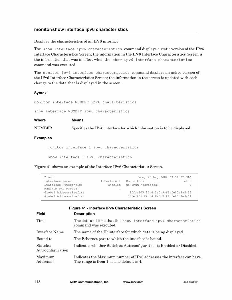
Displays the characteristics of an IPv6 interface.
The show interface ipv6 characteristics command displays a static version of the IPv6 Interface Characteristics Screen; the information in the IPv6 Interface Characteristics Screen is the information that was in effect when the show ipv6 interface characteristics command was executed.
The monitor ipv6 interface characteristics command displays an active version of the IPv6 Interface Characteristics Screen; the information in the screen is updated with each change to the data that is displayed in the screen.
Syntax
monitor interface NUMBER ipv6 characteristics
show interface NUMBER ipv6 characteristics
Where Means
Examples
monitor interface 1 ipv6 characteristics
show interface 1 ipv6 characteristics
Figure 41 shows an example of the Interface IPv6 Characteristics Screen.
Figure 41 - Interface IPv6 Characteristics Screen
monitor/show interface ipv6 characteristics
NUMBER Specifies the IPv6 interface for which information is to be displayed.
Time: Mon, 26 Aug 2002 09:56:22 UTCInterface Name: Interface_1 Bound to : eth0Stateless Autoconfig: Enabled Maximum Addresses: 4Maximum DAD Probes: 1Global Address/Prefix: 3ffe:303:14:4:2a0:9cff:fe00:8ad/64Global Address/Prefix: 3ffe:405:22:14:2a0:9cff:fe00:8ad/64
Field Description
Time The date and time that the show interface ipv6 characteristics command was executed.
Interface Name The name of the IP interface for which data is being displayed.
Bound to The Ethernet port to which the interface is bound.
Stateless Autoconfiguration
Indicates whether Stateless Autoconfiguration is Enabled or Disabled.
Maximum Addresses
Indicates the Maximum number of IPv6 addresses the interface can have. The range is from 1-4. The default is 4.
118 MRV Communications, Inc. www.mrv.com 451-0310P

monitor/show interface ipv6 characteristics (continued)
Field Description
Maximum DAD Probes
Indicates the Maximum number of Duplicate Address Detection probes. The range is from 1-5. The default is 1.
Global Address/Prefix
Indicates the configured IPv6 address(es) for this interface.
451-0310P MRV Communications, Inc. www.mrv.com 119
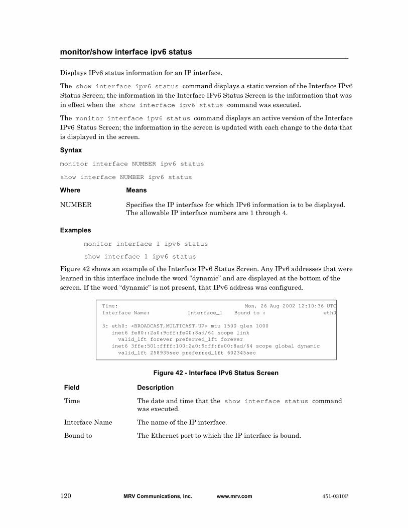
Displays IPv6 status information for an IP interface.
The show interface ipv6 status command displays a static version of the Interface IPv6 Status Screen; the information in the Interface IPv6 Status Screen is the information that was in effect when the show interface ipv6 status command was executed.
The monitor interface ipv6 status command displays an active version of the Interface IPv6 Status Screen; the information in the screen is updated with each change to the data that is displayed in the screen.
Syntax
monitor interface NUMBER ipv6 status
show interface NUMBER ipv6 status
Where Means
Examples
monitor interface 1 ipv6 status
show interface 1 ipv6 status
Figure 42 shows an example of the Interface IPv6 Status Screen. Any IPv6 addresses that were learned in this interface include the word “dynamic” and are displayed at the bottom of the screen. If the word “dynamic” is not present, that IPv6 address was configured.
Figure 42 - Interface IPv6 Status Screen
monitor/show interface ipv6 status
NUMBER Specifies the IP interface for which IPv6 information is to be displayed. The allowable IP interface numbers are 1 through 4.
Time: Mon, 26 Aug 2002 12:10:36 UTCInterface Name: Interface_1 Bound to : eth0
3: eth0: <BROADCAST,MULTICAST,UP> mtu 1500 qlen 1000 inet6 fe80::2a0:9cff:fe00:8ad/64 scope link valid_lft forever preferred_lft forever inet6 3ffe:501:ffff:100:2a0:9cff:fe00:8ad/64 scope global dynamic valid_lft 258935sec preferred_lft 602345sec
Field Description
Time The date and time that the show interface status command was executed.
Interface Name The name of the IP interface.
Bound to The Ethernet port to which the IP interface is bound.
120 MRV Communications, Inc. www.mrv.com 451-0310P

Displays the Telnet port number, and the SSH port number, associated with each serial port on an IP interface.
The show interface port mapping command displays a static version of the Port Mapping Screen; the information in the Port Mapping Screen is the information that was in effect when the show interface port mapping command was executed.
The monitor interface port mapping command displays an active version of the Port Mapping Screen; the information in the screen is updated with each change to the data that is displayed in the screen.
Syntax
monitor interface NUMBER|all port mapping
show interface NUMBER|all port mapping
Where Means
Examples
monitor interface all port mapping
show interface all port mapping
monitor/show interface port mapping
NUMBER Specifies the IP interface for which information is to be displayed.
all Display information for all the IP interfaces on the LX unit.
451-0310P MRV Communications, Inc. www.mrv.com 121
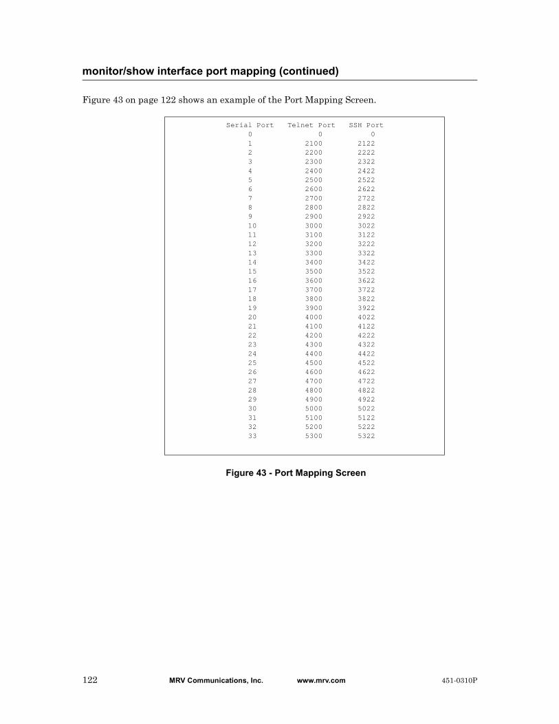
Figure 43 on page 122 shows an example of the Port Mapping Screen.
Figure 43 - Port Mapping Screen
monitor/show interface port mapping (continued)
Serial Port Telnet Port SSH Port 0 0 0 1 2100 2122 2 2200 2222 3 2300 2322 4 2400 2422 5 2500 2522 6 2600 2622 7 2700 2722 8 2800 2822 9 2900 2922 10 3000 3022 11 3100 3122 12 3200 3222 13 3300 3322 14 3400 3422 15 3500 3522 16 3600 3622 17 3700 3722 18 3800 3822 19 3900 3922 20 4000 4022 21 4100 4122 22 4200 4222 23 4300 4322 24 4400 4422 25 4500 4522 26 4600 4622 27 4700 4722 28 4800 4822 29 4900 4922 30 5000 5022 31 5100 5122 32 5200 5222 33 5300 5322
122 MRV Communications, Inc. www.mrv.com 451-0310P
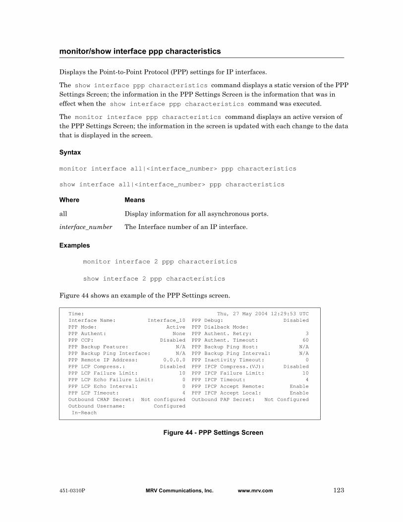
Displays the Point-to-Point Protocol (PPP) settings for IP interfaces.
The show interface ppp characteristics command displays a static version of the PPP Settings Screen; the information in the PPP Settings Screen is the information that was in effect when the show interface ppp characteristics command was executed.
The monitor interface ppp characteristics command displays an active version of the PPP Settings Screen; the information in the screen is updated with each change to the data that is displayed in the screen.
Syntax
monitor interface all|<interface_number> ppp characteristics
show interface all|<interface_number> ppp characteristics
Where Means
Examples
monitor interface 2 ppp characteristics
show interface 2 ppp characteristics
Figure 44 shows an example of the PPP Settings screen.
Figure 44 - PPP Settings Screen
monitor/show interface ppp characteristics
all Display information for all asynchronous ports.
interface_number The Interface number of an IP interface.
Time: Thu, 27 May 2004 12:29:53 UTC Interface Name: Interface_10 PPP Debug: Disabled PPP Mode: Active PPP Dialback Mode: PPP Authent: None PPP Authent. Retry: 3 PPP CCP: Disabled PPP Authent. Timeout: 60 PPP Backup Feature: N/A PPP Backup Ping Host: N/A PPP Backup Ping Interface: N/A PPP Backup Ping Interval: N/A PPP Remote IP Address: 0.0.0.0 PPP Inactivity Timeout: 0 PPP LCP Compress.: Disabled PPP IPCP Compress.(VJ): Disabled PPP LCP Failure Limit: 10 PPP IPCP Failure Limit: 10 PPP LCP Echo Failure Limit: 0 PPP IPCP Timeout: 4 PPP LCP Echo Interval: 0 PPP IPCP Accept Remote: Enable PPP LCP Timeout: 4 PPP IPCP Accept Local: Enable Outbound CHAP Secret: Not configured Outbound PAP Secret: Not Configured Outbound Username: Configured In-Reach
451-0310P MRV Communications, Inc. www.mrv.com 123
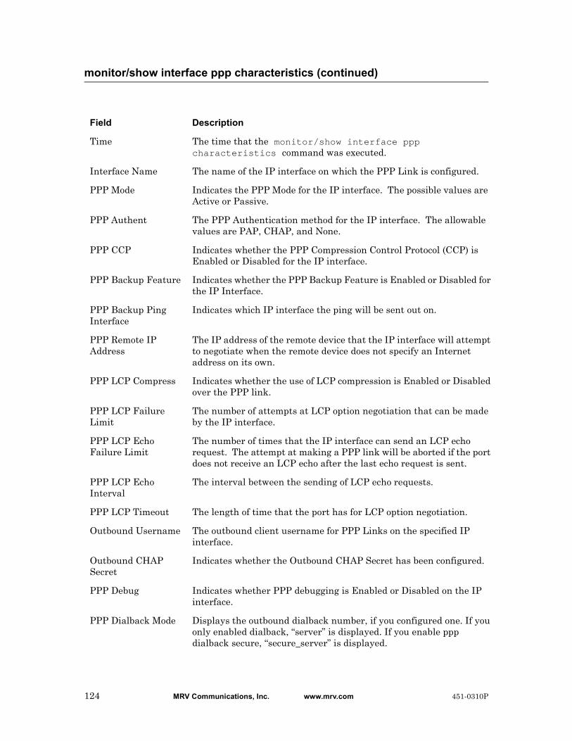
monitor/show interface ppp characteristics (continued)
Field Description
Time The time that the monitor/show interface ppp characteristics command was executed.
Interface Name The name of the IP interface on which the PPP Link is configured.
PPP Mode Indicates the PPP Mode for the IP interface. The possible values are Active or Passive.
PPP Authent The PPP Authentication method for the IP interface. The allowable values are PAP, CHAP, and None.
PPP CCP Indicates whether the PPP Compression Control Protocol (CCP) is Enabled or Disabled for the IP interface.
PPP Backup Feature Indicates whether the PPP Backup Feature is Enabled or Disabled for the IP Interface.
PPP Backup Ping Interface
Indicates which IP interface the ping will be sent out on.
PPP Remote IP Address
The IP address of the remote device that the IP interface will attempt to negotiate when the remote device does not specify an Internet address on its own.
PPP LCP Compress Indicates whether the use of LCP compression is Enabled or Disabled over the PPP link.
PPP LCP Failure Limit
The number of attempts at LCP option negotiation that can be made by the IP interface.
PPP LCP Echo Failure Limit
The number of times that the IP interface can send an LCP echo request. The attempt at making a PPP link will be aborted if the port does not receive an LCP echo after the last echo request is sent.
PPP LCP Echo Interval
The interval between the sending of LCP echo requests.
PPP LCP Timeout The length of time that the port has for LCP option negotiation.
Outbound Username The outbound client username for PPP Links on the specified IP interface.
Outbound CHAP Secret
Indicates whether the Outbound CHAP Secret has been configured.
PPP Debug Indicates whether PPP debugging is Enabled or Disabled on the IP interface.
PPP Dialback Mode Displays the outbound dialback number, if you configured one. If you only enabled dialback, “server” is displayed. If you enable ppp dialback secure, “secure_server” is displayed.
124 MRV Communications, Inc. www.mrv.com 451-0310P
monitor/show interface ppp characteristics (continued)
PPP Authent. Retry The number of times that the port can attempt to authenticate a PPP link.
PPP Authent. Timeout
The length of time that the port has to authenticate a PPP link.
PPP Backup Ping Host
The Host Address of the PPP Ping Backup.
PPP Backup Ping Interval
Indicates the number of seconds between ping requests.
PPP Inactivity Timeout
The length of time (in seconds) that the PPP link will wait for an LCP echo reply before closing the PPP Link on the IP interface.
PPP IPCP Compress. (VJ)
Indicates whether the use of Van Jacobson (VJ) compression is Enabled or Disabled over the PPP link.
PPP IPCP Failure Limit
The number of attempts at IPCP option negotiation that can be made by the IP interface.
PPP IPCP Timeout The length of time that the IP interface has for IPCP option negotiation.
PPP IPCP Accept Remote
Indicates whether the IP interface is configured to accept or reject the negotiation of remote addresses. If the value is Enabled, the IP interface is configured to accept the negotiation of remote addresses. If the value is Disabled, the IP interface is configured to reject the negotiation of remote addresses.
PPP IPCP Accept Local
Indicates whether the IP interface is configured to accept or reject the negotiation of local addresses. If the value is Enabled, the IP interface is configured to accept the negotiation of local addresses. If the value is Disabled, the IP interface is configured to reject the negotiation of local addresses.
Outbound PAP Secret
Indicates whether the Outbound PAP Secret has been configured.
451-0310P MRV Communications, Inc. www.mrv.com 125
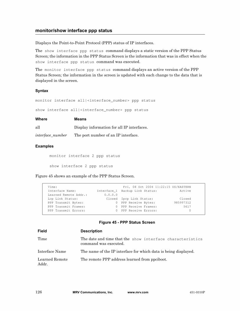
Displays the Point-to-Point Protocol (PPP) status of IP interfaces.
The show interface ppp status command displays a static version of the PPP Status Screen; the information in the PPP Status Screen is the information that was in effect when the show interface ppp status command was executed.
The monitor interface ppp status command displays an active version of the PPP Status Screen; the information in the screen is updated with each change to the data that is displayed in the screen.
Syntax
monitor interface all|<interface_number> ppp status
show interface all|<interface_number> ppp status
Where Means
Examples
monitor interface 2 ppp status
show interface 2 ppp status
Figure 45 shows an example of the PPP Status Screen.
Figure 45 - PPP Status Screen
monitor/show interface ppp status
all Display information for all IP interfaces.
interface_number The port number of an IP interface.
Time: Fri, 08 Oct 2004 11:22:15 US/EASTERN Interface Name: Interface_1 Backup Link Status: Active Learned Remote Addr.: 0.0.0.0 Lcp Link Status: Closed Ipcp Link Status: Closed PPP Transmit Bytes: 0 PPP Receive Bytes: 985997312 PPP Transmit Frames: 0 PPP Receive Frames: 5617 PPP Transmit Errors: 0 PPP Receive Errors: 0
Field Description
Time The date and time that the show interface characteristics command was executed.
Interface Name The name of the IP interface for which data is being displayed.
Learned Remote Addr.
The remote PPP address learned from ppciboot.
126 MRV Communications, Inc. www.mrv.com 451-0310P
monitor/show interface ppp status (continued)
Lcp Link Status Indicates the status of the LCP Link for the PPP session.
PPP Transmit Bytes The number of bytes that have been transmitted in the current PPP session.
PPP Transmit Frames
The number of frames that have been transmitted in the current PPP session.
PPP Transmit Errors
The number of frames containing errors that have been transmitted in the current PPP session.
Backup Link Status Indicates whether the PPP backup link is active. Options are Active or Inactive.
Ipcp Link Status Indicates the status of the IPCP Link for the PPP session.
PPP Receive Bytes The number of bytes that have been received in the current PPP session.
PPP Receive Frames The number of frames that have been received in the current PPP session.
PPP Receive Errors The number of frames containing errors that have been transmitted in the current PPP session.
451-0310P MRV Communications, Inc. www.mrv.com 127

Displays the characteristics of a rotary.
The show interface rotary command displays a static version of the Rotary Characteristics Screen; the information in the Rotary Characteristics Screen is the information that was in effect when the show interface rotary command was executed.
The monitor interface rotary command displays an active version of the Rotary Characteristics Screen; the information in the screen is updated with each change to the data that is displayed in the screen.
Syntax
monitor interface NUMBER|all rotary
show interface NUMBER|all rotary
Where Means
Examples
monitor interface 3 rotary
show interface 3 rotary
Figure 46 shows an example of the Rotary Characteristics Screen.
Figure 46 - Rotary Characteristics Screen
monitor/show interface rotary
NUMBER Specifies the rotary for which information is to be displayed. The allowable rotary numbers are 1 through 4.
all Display information for all the rotaries on the LX unit.
Rotary IP Address TCP SSH Rotary Type Rotary State Serial Ports 147.132.145.16 1500 1522 First Available Disabled
Field Description
Rotary IP Address The IP Address of the rotary. (This is also the IP Address of the interface.)
TCP The TCP socket number assigned to the rotary.
SSH The SSH socket number assigned to the rotary.
Rotary Type The rotary type (First Available or Round Robin).
Rotary State Indicates whether the rotary is Enabled or Disabled.
Serial Ports The serial ports included in the rotary.
128 MRV Communications, Inc. www.mrv.com 451-0310P

Displays status information for an IP interface.
The show interface status command displays a static version of the Interface Status Screen; the information in the Interface Status Screen is the information that was in effect when the show interface status command was executed.
The monitor interface status command displays an active version of the Interface Status Screen; the information in the screen is updated with each change to the data that is displayed in the screen.
Syntax
monitor interface NUMBER|all status
show interface NUMBER|all status
Where Means
Examples
monitor interface 1 status
show interface 1 status
Figure 47 shows an example of the Interface Status Screen.
Figure 47 - Interface Status Screen
monitor/show interface status
NUMBER Specifies the IP interface for which information is to be displayed. The allowable IP interface numbers are 1 through 4.
all Display information for all the IP interfaces on the LX unit.
Time: Mon 24 Apr 2003 16:19:34Interface Name: Interface_1 Bound to : eth0IP Address: 102.19.169.191 IP Mask: 255.255.255.0IP Broadcast Addr: 102.19.169.255
Field Description
Time The date and time that the show interface status command was executed.
Interface Name The name of the IP interface.
IP Address The IP Address of the IP interface.
IP Broadcast Addr The IP Broadcast Address of the IP interface.
451-0310P MRV Communications, Inc. www.mrv.com 129

monitor/show interface status (continued)
Bound to The Ethernet port to which the IP interface is bound.
IP Mask The Subnet Mask of the IP interface.
130 MRV Communications, Inc. www.mrv.com 451-0310P

Displays summary information on all of the IP interfaces that are configured on the LX unit.
The show interface summary command displays a static version of the Interfaces Summary Screen; the information in the Interfaces Summary Screen is the information that was in effect when the show interface summary command was executed.
The monitor interface summary command displays an active version of the Interfaces Summary Screen; the information in the screen is updated with each change to the data that is displayed in the screen.
Syntax
monitor interface summary
show interface summary
Examples
monitor interface summary
show interface summary
Figure 48 shows an example of the Interfaces Summary Screen.
Figure 48 - Interfaces Summary Screen
monitor/show interface summary
Name Address Broadcast Addr. Mask Bound toInterface_1 *157.145.162.155 157.145.162.255 *255.255.255.0 bond0Interface_2 0.0.0.0 0.0.0.0 0.0.0.0 eth0:1Interface_3 0.0.0.0 0.0.0.0 0.0.0.0 eth0:2Interface_4 0.0.0.0 0.0.0.0 0.0.0.0 eth0:3
'*' before the value denote it was learned from ppciboot
Field Description
Name The name of the IP interface.
Address The IP Address configured for the IP interface.
Broadcast The Broadcast Address configured for the IP interface.
Addr. Mask The subnet mask configured for the IP interface.
Bound to The Ethernet port to which the IP interface is bound.
451-0310P MRV Communications, Inc. www.mrv.com 131
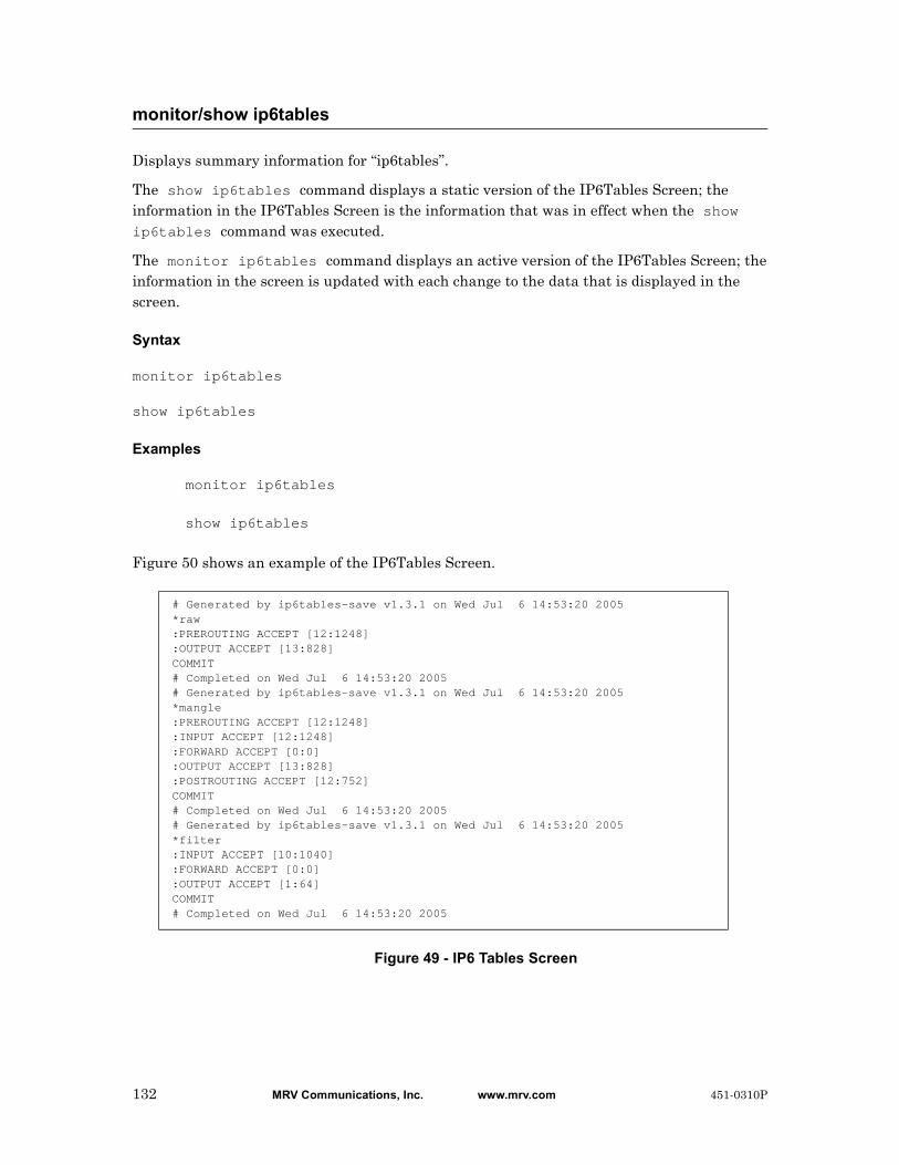
Displays summary information for “ip6tables”.
The show ip6tables command displays a static version of the IP6Tables Screen; the information in the IP6Tables Screen is the information that was in effect when the show ip6tables command was executed.
The monitor ip6tables command displays an active version of the IP6Tables Screen; the information in the screen is updated with each change to the data that is displayed in the screen.
Syntax
monitor ip6tables
show ip6tables
Examples
monitor ip6tables
show ip6tables
Figure 50 shows an example of the IP6Tables Screen.
Figure 49 - IP6 Tables Screen
monitor/show ip6tables
# Generated by ip6tables-save v1.3.1 on Wed Jul 6 14:53:20 2005*raw:PREROUTING ACCEPT [12:1248]:OUTPUT ACCEPT [13:828]COMMIT# Completed on Wed Jul 6 14:53:20 2005# Generated by ip6tables-save v1.3.1 on Wed Jul 6 14:53:20 2005*mangle:PREROUTING ACCEPT [12:1248]:INPUT ACCEPT [12:1248]:FORWARD ACCEPT [0:0]:OUTPUT ACCEPT [13:828]:POSTROUTING ACCEPT [12:752]COMMIT# Completed on Wed Jul 6 14:53:20 2005# Generated by ip6tables-save v1.3.1 on Wed Jul 6 14:53:20 2005*filter:INPUT ACCEPT [10:1040]:FORWARD ACCEPT [0:0]:OUTPUT ACCEPT [1:64]COMMIT# Completed on Wed Jul 6 14:53:20 2005
132 MRV Communications, Inc. www.mrv.com 451-0310P
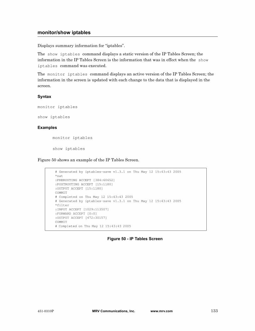
Displays summary information for “iptables”.
The show iptables command displays a static version of the IP Tables Screen; the information in the IP Tables Screen is the information that was in effect when the show iptables command was executed.
The monitor iptables command displays an active version of the IP Tables Screen; the information in the screen is updated with each change to the data that is displayed in the screen.
Syntax
monitor iptables
show iptables
Examples
monitor iptables
show iptables
Figure 50 shows an example of the IP Tables Screen.
Figure 50 - IP Tables Screen
monitor/show iptables
# Generated by iptables-save v1.3.1 on Thu May 12 15:43:43 2005*nat:PREROUTING ACCEPT [384:60652]:POSTROUTING ACCEPT [15:1180]:OUTPUT ACCEPT [15:1180]COMMIT# Completed on Thu May 12 15:43:43 2005# Generated by iptables-save v1.3.1 on Thu May 12 15:43:43 2005*filter:INPUT ACCEPT [1029:113507]:FORWARD ACCEPT [0:0]:OUTPUT ACCEPT [472:30157]COMMIT# Completed on Thu May 12 15:43:43 2005
451-0310P MRV Communications, Inc. www.mrv.com 133
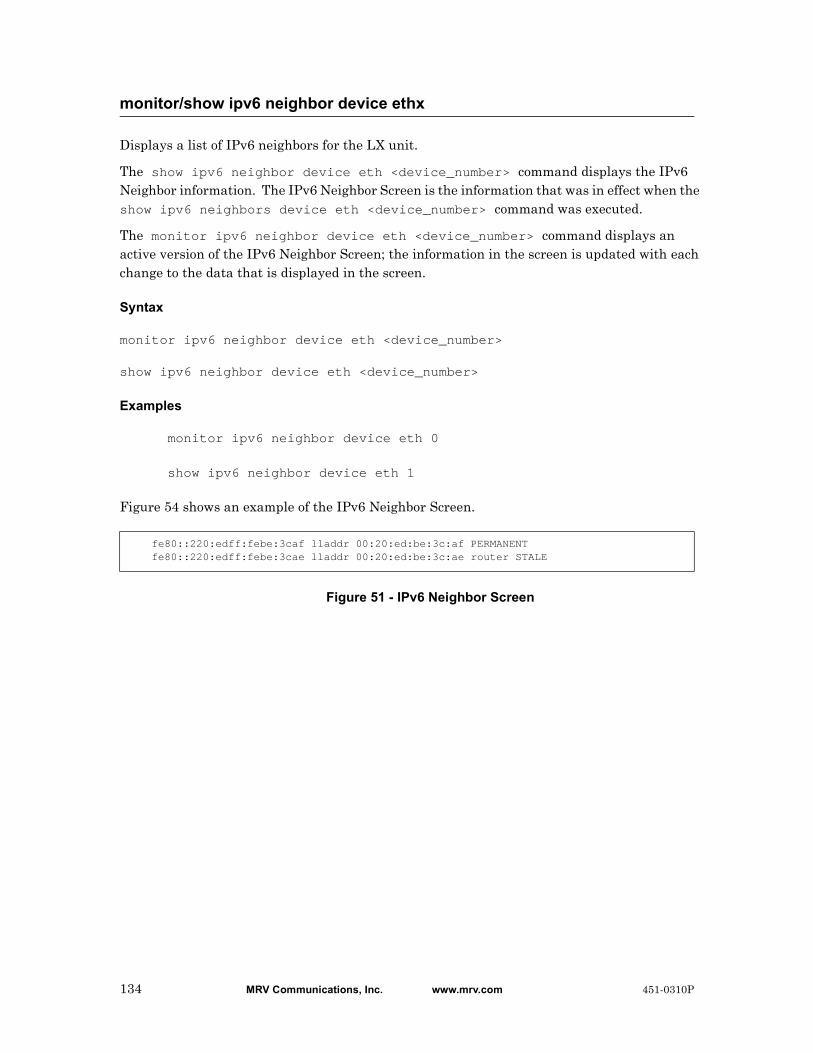
Displays a list of IPv6 neighbors for the LX unit.
The show ipv6 neighbor device eth <device_number> command displays the IPv6 Neighbor information. The IPv6 Neighbor Screen is the information that was in effect when the show ipv6 neighbors device eth <device_number> command was executed.
The monitor ipv6 neighbor device eth <device_number> command displays an active version of the IPv6 Neighbor Screen; the information in the screen is updated with each change to the data that is displayed in the screen.
Syntax
monitor ipv6 neighbor device eth <device_number>
show ipv6 neighbor device eth <device_number>
Examples
monitor ipv6 neighbor device eth 0
show ipv6 neighbor device eth 1
Figure 54 shows an example of the IPv6 Neighbor Screen.
Figure 51 - IPv6 Neighbor Screen
monitor/show ipv6 neighbor device ethx
fe80::220:edff:febe:3caf lladdr 00:20:ed:be:3c:af PERMANENTfe80::220:edff:febe:3cae lladdr 00:20:ed:be:3c:ae router STALE
134 MRV Communications, Inc. www.mrv.com 451-0310P
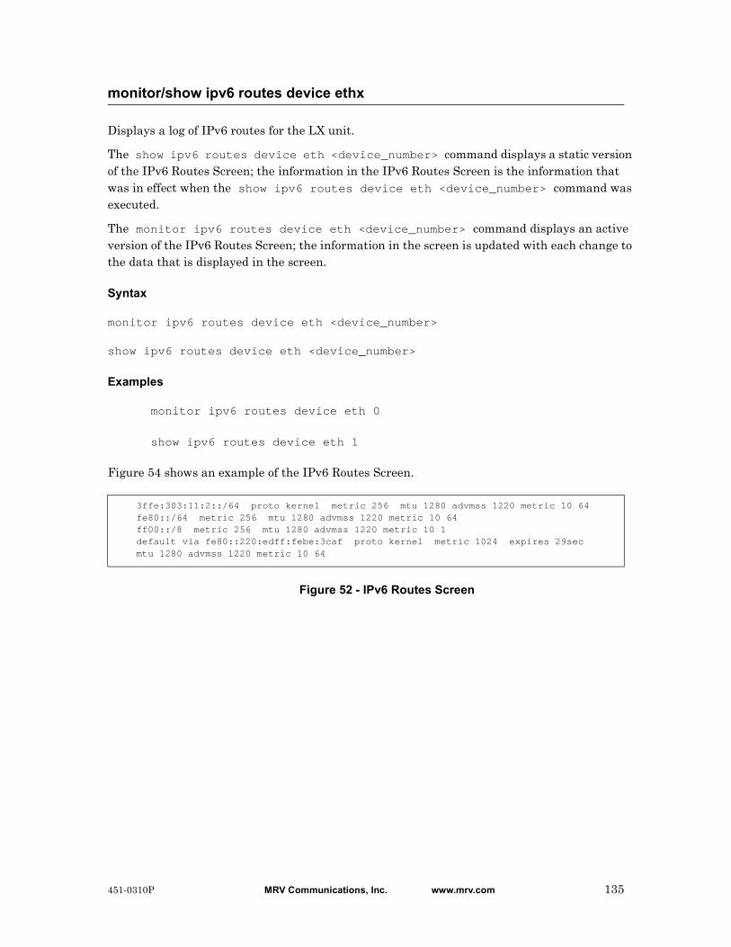
Displays a log of IPv6 routes for the LX unit.
The show ipv6 routes device eth <device_number> command displays a static version of the IPv6 Routes Screen; the information in the IPv6 Routes Screen is the information that was in effect when the show ipv6 routes device eth <device_number> command was executed.
The monitor ipv6 routes device eth <device_number> command displays an active version of the IPv6 Routes Screen; the information in the screen is updated with each change to the data that is displayed in the screen.
Syntax
monitor ipv6 routes device eth <device_number>
show ipv6 routes device eth <device_number>
Examples
monitor ipv6 routes device eth 0
show ipv6 routes device eth 1
Figure 54 shows an example of the IPv6 Routes Screen.
Figure 52 - IPv6 Routes Screen
monitor/show ipv6 routes device ethx
3ffe:303:11:2::/64 proto kernel metric 256 mtu 1280 advmss 1220 metric 10 64fe80::/64 metric 256 mtu 1280 advmss 1220 metric 10 64ff00::/8 metric 256 mtu 1280 advmss 1220 metric 10 1default via fe80::220:edff:febe:3caf proto kernel metric 1024 expires 29secmtu 1280 advmss 1220 metric 10 64
451-0310P MRV Communications, Inc. www.mrv.com 135

Displays the characteristics of all IPv6 tunnels, or a specific tunnel.
The show ipv6 tunnel all|<tunnel_name> command displays a static version of the IPv6 Tunnel Screen; the information in the IPv6 Tunnel Screen is the information that was in effect when the show ipv6 tunnel all|<tunnel_name> command was executed.
The monitor ipv6 tunnel all|<tunnel_name> command displays an active version of the IPv6 Tunnel Screen; the information in the screen is updated with each change to the data that is displayed in the screen.
Syntax
monitor ipv6 tunnel all|<tunnel_name>
show ipv6 tunnel all|<tunnel_name>
Where Means
Examples
show ipv6 tunnel all
show ipv6 tunnel rem-6to4
Figure 41 shows an example of the IPv6 Tunnel Screen.
Figure 53 - IPv6 Tunnel Information Screen
monitor/show ipv6 tunnel
tunnel_name Specifies the IPv6 tunnel for which information is to be displayed.
Tunnel Name 6to4localTunnel Address: 2002:8cb3:6432::1/16Tunnel Local Address: 140.179.100.50Tunnel Remote Address: anyTunnel TTL: 244
Field Description
Tunnel Name The name of the tunnel.
Tunnel Address The IPv6 address of the device attached to the tunnel.
Tunnel Local Address
The local IPv4 address.
Tunnel Remote Address
The remote IPv6 address of the device attached to the tunnel.
Tunnel TTL The number of seconds in the packet TTL. The range is 0-255. The default is 255.
136 MRV Communications, Inc. www.mrv.com 451-0310P
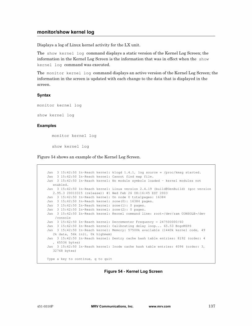
Displays a log of Linux kernel activity for the LX unit.
The show kernel log command displays a static version of the Kernel Log Screen; the information in the Kernel Log Screen is the information that was in effect when the show kernel log command was executed.
The monitor kernel log command displays an active version of the Kernel Log Screen; the information in the screen is updated with each change to the data that is displayed in the screen.
Syntax
monitor kernel log
show kernel log
Examples
monitor kernel log
show kernel log
Figure 54 shows an example of the Kernel Log Screen.
Figure 54 - Kernel Log Screen
monitor/show kernel log
Jan 3 15:42:50 In-Reach kernel: klogd 1.4.1, log source = /proc/kmsg started.Jan 3 15:42:50 In-Reach kernel: Cannot find map file.Jan 3 15:42:50 In-Reach kernel: No module symbols loaded - kernel modules not enabled.Jan 3 15:42:50 In-Reach kernel: Linux version 2.4.19 (build@GenBuild) (gcc version 2.95.3 20010315 (release)) #1 Wed Feb 26 08:16:45 EST 2003Jan 3 15:42:50 In-Reach kernel: On node 0 totalpages: 16384Jan 3 15:42:50 In-Reach kernel: zone(0): 16384 pages.Jan 3 15:42:50 In-Reach kernel: zone(1): 0 pages.Jan 3 15:42:50 In-Reach kernel: zone(2): 0 pages.Jan 3 15:42:50 In-Reach kernel: Kernel command line: root=/dev/ram CONSOLE=/dev /consoleJan 3 15:42:50 In-Reach kernel: Decrementer Frequency = 247500000/60Jan 3 15:42:50 In-Reach kernel: Calibrating delay loop... 65.53 BogoMIPSJan 3 15:42:50 In-Reach kernel: Memory: 57500k available (1440k kernel code, 49 2k data, 56k init, 0k highmem)Jan 3 15:42:50 In-Reach kernel: Dentry cache hash table entries: 8192 (order: 4 , 65536 bytes)Jan 3 15:42:50 In-Reach kernel: Inode cache hash table entries: 4096 (order: 3, 32768 bytes)
Type a key to continue, q to quit
451-0310P MRV Communications, Inc. www.mrv.com 137

Displays information about the LDAP configuration for the LX unit.
The show ldap characteristics command displays a static version of the LDAP Characteristics Screen; the information in the LDAP Characteristics Screen is the information that was in effect when the show ldap characteristics command was executed.
The monitor ldap characteristics command displays an active version of the LDAP Characteristics Screen; the information in the screen is updated with each change to the data that is displayed in the screen.
Syntax
monitor ldap characteristics
show ldap characteristics
Examples
monitor ldap characteristics
show ldap characteristics
Figure 55 shows an example of the LDAP Characteristics Screen.
Figure 55 - LDAP Characteristics Screen
monitor/show ldap characteristics
Time: Thu, 14 Aug 2003 02:56:43 UTC Primary LDAP Authentication Server: IP Address: 0.0.0.0 LDAP Auth. TCP Port: 389 LDAP Base DN: Timeout: 5 Retry: 3 Secondary LDAP Authentication Server: IP Address: 0.0.0.0 LDAP Auth. TCP Port: 389 LDAP Base DN: Timeout: 5 Retry: 3 Local Subscriber: Disabled Inbound LDAP Enabled Serial Ports: Outbound LDAP Enabled Serial Ports: LDAP Enabled Interfaces:
Field Description
IP Address The IP Address for the Primary or Secondary LDAP Authentication Server.
LDAP Base DN The Search Path of the Primary or Secondary LDAP Authentication Server.
Retry The number of times the LX unit will attempt to connect to the LDAP server.
138 MRV Communications, Inc. www.mrv.com 451-0310P
monitor/show ldap characteristics (continued)
LDAP Auth. TCP Port
The TCP port that the LX unit and the applicable LDAP authentication server will use for communication.
Timeout The time to wait for the Primary or Secondary LDAP Authentication server to respond before retransmitting packets to the server.
Local Subscriber The state of the LDAP Local Subscriber Feature. The allowable values are Enabled, Disabled, and Only.
Inbound LDAP Enabled Serial Ports
The Inbound serial ports that are enabled for LDAP.
Outbound LDAP Enabled Serial Ports
The Outbound serial ports that are enabled for LDAP.
LDAP Enabled Interfaces
The LX interfaces that are enabled for LDAP.
451-0310P MRV Communications, Inc. www.mrv.com 139
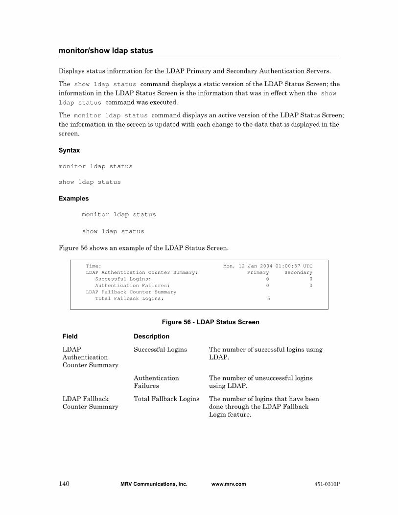
Displays status information for the LDAP Primary and Secondary Authentication Servers.
The show ldap status command displays a static version of the LDAP Status Screen; the information in the LDAP Status Screen is the information that was in effect when the show ldap status command was executed.
The monitor ldap status command displays an active version of the LDAP Status Screen; the information in the screen is updated with each change to the data that is displayed in the screen.
Syntax
monitor ldap status
show ldap status
Examples
monitor ldap status
show ldap status
Figure 56 shows an example of the LDAP Status Screen.
Figure 56 - LDAP Status Screen
monitor/show ldap status
Time: Mon, 12 Jan 2004 01:00:57 UTCLDAP Authentication Counter Summary: Primary Secondary Successful Logins: 0 0 Authentication Failures: 0 0LDAP Fallback Counter Summary Total Fallback Logins: 5
Field Description
LDAP Authentication Counter Summary
Successful Logins The number of successful logins using LDAP.
Authentication Failures
The number of unsuccessful logins using LDAP.
LDAP Fallback Counter Summary
Total Fallback Logins The number of logins that have been done through the LDAP Fallback Login feature.
140 MRV Communications, Inc. www.mrv.com 451-0310P

Displays summary information for the LDAP Primary and Secondary Authentication Servers.
The show ldap summary command displays a static version of the LDAP Summary Screen; the information in the LDAP Summary Screen is the information that was in effect when the show ldap summary command was executed.
The monitor ldap summary command displays an active version of the LDAP Summary Screen; the information in the screen is updated with each change to the data that is displayed in the screen.
Syntax
monitor ldap summary
show ldap summary
Examples
monitor ldap summary
show ldap summary
Figure 57 shows an example of the LDAP Summary Screen.
Figure 57 - LDAP Summary Screen
monitor/show ldap summary
LDAP Server Summary Thu, 14 Aug 2003 03:20:00 UTC Primary Auth. Server: 0.0.0.0 Primary Auth. TCP Port: 389 Secondary Auth. Server: 0.0.0.0 Secondary Auth. TCP Port: 389
Field Description
Primary Auth. Server
The IP Address of the Primary LDAP Authentication server.
Secondary Auth. Server
The IP Address of the Secondary LDAP Authentication server.
Primary Auth. TCP Port
The TCP port for the Primary LDAP Authentication server.
Secondary Auth. TCP Port
The TCP port for the Secondary LDAP Authentication server.
451-0310P MRV Communications, Inc. www.mrv.com 141
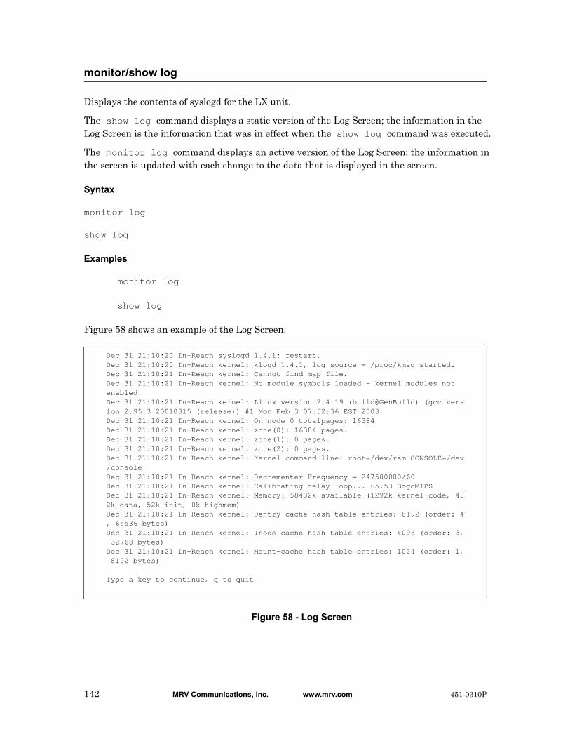
Displays the contents of syslogd for the LX unit.
The show log command displays a static version of the Log Screen; the information in the Log Screen is the information that was in effect when the show log command was executed.
The monitor log command displays an active version of the Log Screen; the information in the screen is updated with each change to the data that is displayed in the screen.
Syntax
monitor log
show log
Examples
monitor log
show log
Figure 58 shows an example of the Log Screen.
Figure 58 - Log Screen
monitor/show log
Dec 31 21:10:20 In-Reach syslogd 1.4.1: restart.Dec 31 21:10:20 In-Reach kernel: klogd 1.4.1, log source = /proc/kmsg started.Dec 31 21:10:21 In-Reach kernel: Cannot find map file.Dec 31 21:10:21 In-Reach kernel: No module symbols loaded - kernel modules not enabled.Dec 31 21:10:21 In-Reach kernel: Linux version 2.4.19 (build@GenBuild) (gcc version 2.95.3 20010315 (release)) #1 Mon Feb 3 07:52:36 EST 2003Dec 31 21:10:21 In-Reach kernel: On node 0 totalpages: 16384Dec 31 21:10:21 In-Reach kernel: zone(0): 16384 pages.Dec 31 21:10:21 In-Reach kernel: zone(1): 0 pages.Dec 31 21:10:21 In-Reach kernel: zone(2): 0 pages.Dec 31 21:10:21 In-Reach kernel: Kernel command line: root=/dev/ram CONSOLE=/dev/consoleDec 31 21:10:21 In-Reach kernel: Decrementer Frequency = 247500000/60Dec 31 21:10:21 In-Reach kernel: Calibrating delay loop... 65.53 BogoMIPSDec 31 21:10:21 In-Reach kernel: Memory: 58432k available (1292k kernel code, 432k data, 52k init, 0k highmem)Dec 31 21:10:21 In-Reach kernel: Dentry cache hash table entries: 8192 (order: 4, 65536 bytes)Dec 31 21:10:21 In-Reach kernel: Inode cache hash table entries: 4096 (order: 3, 32768 bytes)Dec 31 21:10:21 In-Reach kernel: Mount-cache hash table entries: 1024 (order: 1, 8192 bytes)
Type a key to continue, q to quit
142 MRV Communications, Inc. www.mrv.com 451-0310P
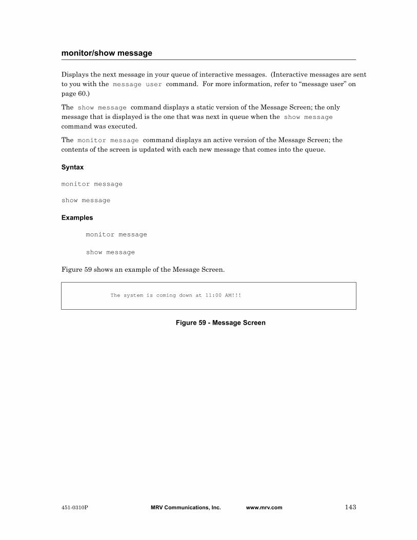
Displays the next message in your queue of interactive messages. (Interactive messages are sent to you with the message user command. For more information, refer to “message user” on page 60.)
The show message command displays a static version of the Message Screen; the only message that is displayed is the one that was next in queue when the show message command was executed.
The monitor message command displays an active version of the Message Screen; the contents of the screen is updated with each new message that comes into the queue.
Syntax
monitor message
show message
Examples
monitor message
show message
Figure 59 shows an example of the Message Screen.
Figure 59 - Message Screen
monitor/show message
The system is coming down at 11:00 AM!!!
451-0310P MRV Communications, Inc. www.mrv.com 143
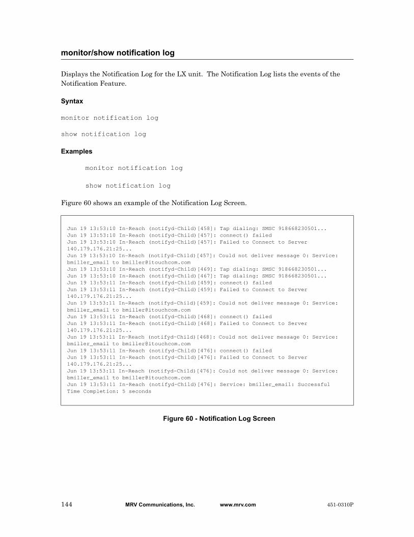
Displays the Notification Log for the LX unit. The Notification Log lists the events of the Notification Feature.
Syntax
monitor notification log
show notification log
Examples
monitor notification log
show notification log
Figure 60 shows an example of the Notification Log Screen.
Figure 60 - Notification Log Screen
monitor/show notification log
Jun 19 13:53:10 In-Reach (notifyd-Child)[458]: Tap dialing: SMSC 918668230501... Jun 19 13:53:10 In-Reach (notifyd-Child)[457]: connect() failed Jun 19 13:53:10 In-Reach (notifyd-Child)[457]: Failed to Connect to Server 140.179.176.21:25... Jun 19 13:53:10 In-Reach (notifyd-Child)[457]: Could not deliver message 0: Service: bmiller_email to [email protected] Jun 19 13:53:10 In-Reach (notifyd-Child)[469]: Tap dialing: SMSC 918668230501... Jun 19 13:53:10 In-Reach (notifyd-Child)[467]: Tap dialing: SMSC 918668230501... Jun 19 13:53:11 In-Reach (notifyd-Child)[459]: connect() failed Jun 19 13:53:11 In-Reach (notifyd-Child)[459]: Failed to Connect to Server 140.179.176.21:25... Jun 19 13:53:11 In-Reach (notifyd-Child)[459]: Could not deliver message 0: Service: bmiller_email to [email protected] Jun 19 13:53:11 In-Reach (notifyd-Child)[468]: connect() failed Jun 19 13:53:11 In-Reach (notifyd-Child)[468]: Failed to Connect to Server 140.179.176.21:25... Jun 19 13:53:11 In-Reach (notifyd-Child)[468]: Could not deliver message 0: Service: bmiller_email to [email protected] Jun 19 13:53:11 In-Reach (notifyd-Child)[476]: connect() failed Jun 19 13:53:11 In-Reach (notifyd-Child)[476]: Failed to Connect to Server 140.179.176.21:25... Jun 19 13:53:11 In-Reach (notifyd-Child)[476]: Could not deliver message 0: Service: bmiller_email to [email protected] Jun 19 13:53:11 In-Reach (notifyd-Child)[476]: Service: bmiller_email: Successful Time Completion: 5 seconds
144 MRV Communications, Inc. www.mrv.com 451-0310P

Displays the ID number, string portion (message), facility, and priority of configurable syslogd messages.
The show notification message command displays a static version of the Message Screen; the information in the Message Screen is the information that was in effect when the show notification message command was executed.
The monitor notification message command displays an active version of the Message Screen; the information in the screen is updated with each change to the data that is displayed in the screen.
Syntax
monitor notification message NUMBER|all
show notification message NUMBER|all
Where Means
Examples
monitor notification message 4
show notification message 4
Figure 61 shows an example of the Message Screen.
Figure 61 - Message Screen
monitor/show notification message
NUMBER The ID number of a configurable syslogd message.
all Display all of the configurable syslogd messages on the LX unit.
Message record 4: Message: The Shell has been exited by Facility: user Priority: notice
451-0310P MRV Communications, Inc. www.mrv.com 145

Displays information on Service Profiles configured for the Notification Feature.
The show notification profile service command displays a static version of the Service Profile Screen; the information in the Service Profile Screen is the information that was in effect when the show notification profile service command was executed.
The monitor notification profile service command displays an active version of the Service Profile Screen; the information in the screen is updated with each change to the data that is displayed in the screen.
Syntax
monitor notification profile service <name>|all
show notification profile service <name>|all
Where Means
Examples
monitor notification profile service all
show notification profile service all
Figure 62 shows an example of the Service Profile Screen.
Figure 62 - Service Profile Screen
monitor/show notification profile service
name The Service Profile for which data is to be displayed.
all Display the specified data for all Service Profiles on the LX unit.
ServiceProfile: Server16 Protocol: smtpServer: 160.120.100.16 Email Name; JohnDoeEmail Subject: System Notification from LX2
ServiceProfile: Server17 Protocol: smtpServer: 160.120.100.17 Email Name; JaneDoeEmail Subject: System Notification from LX2
ServiceProfile: jackasync Protocol: asyncAsync Port: 5
ServiceProfile: jack Protocol: tapSMSC: 18668230501 Bits/Parity/StopBits:8N1Modem Port(s): 33
ServiceProfile: webjack Protocol: webDriver: verizon_web
146 MRV Communications, Inc. www.mrv.com 451-0310P

Displays information on User Profiles of the Notification Feature.
The show notification profile user command displays a static version of the User Profile Screen; the information in the User Profile Screen is the information that was in effect when the show notification profile user command was executed.
The monitor notification profile user command displays an active version of the User Profile Screen; the information in the screen is updated with each change to the data that is displayed in the screen.
Syntax
monitor notification profile user <name>|all
show notification profile user <name>|all
Where Means
Example
monitor notification profile user all
show notification profile user all
Figure 63 shows an example of the User Profile Screen.
Figure 63 - User Profile Screen
monitor/show notification profile user
name The User Profile for which data is to be displayed.
all Display the specified data for all User Profiles on the LX unit.
UserProfile: debug ServiceProfile: debugContact:Facility: all Priority: debug
UserProfile: grogers@mrv ServiceProfile: N/AContact:Facility: kern Priority: emerg
UserProfile: mark ServiceProfile: N/AContact:Facility: kern Priority: emerg
UserProfile: jacklocal ServiceProfile: jacklocalContact:Facility: user Priority: warning
451-0310P MRV Communications, Inc. www.mrv.com 147

Displays the characteristics of outlets.
The show outlet command displays a static version of the Outlet Characteristics Screen; the information in the Outlet Characteristics Screen is the information that was in effect when the show outlet command was executed.
The monitor outlet command displays an active version of the Outlet Characteristics Screen; the information in the screen is updated with each change to the data that is displayed in the screen.
Syntax
monitor outlet <outlet_list>|all
show outlet <outlet_list>|all
Where Means
Usage Guidelines
If the Outlet Management Feature is enabled, this command will display only those outlets that you can manage from your subscriber account. If the Outlet Management Feature is disabled, this command will display all of the outlets on the LX unit. For more information on the Outlet Management Feature, refer to “outlet access enable” on page 358.
Examples
monitor outlet all
monitor outlet 4:5
monitor outlet 7-9:2 9:3-7 10:2 11:3
monitor/show outlet
outlet_list Specifies the outlets for which data is to be displayed. The Power Port number, combined with the outlet number, identifies each outlet. The Power Port number and the outlet number are separated by a colon (:). For example, 2:5 identifies outlet 5 on the device that is managed from port 2.
If you specify more than one outlet in the outlet_list, the outlets must be separated by blank spaces; for example, 2:5 3:7 4:2 4:3 4:5. Up to 99 outlets can be included in an outlet group.
You can specify a range of port numbers, or a range of outlets, by placing a hyphen between the first and last port number, or the first and last outlet, in the range. For example, 2-4:1 specifies outlet 1 on ports 2 through 4; 2:1-5 specifies outlets 1 through 5 on port 2.
all Display the characteristics of all outlets that are managed from the LX unit.
148 MRV Communications, Inc. www.mrv.com 451-0310P
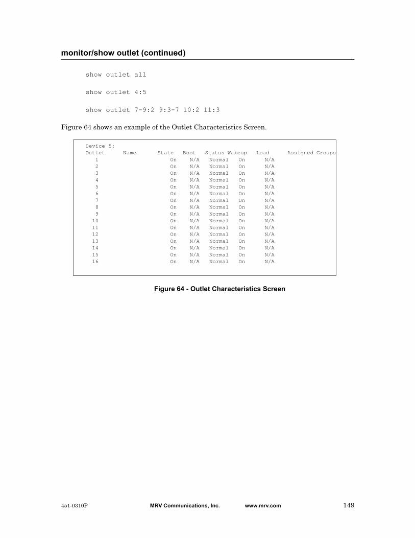
show outlet all
show outlet 4:5
show outlet 7-9:2 9:3-7 10:2 11:3
Figure 64 shows an example of the Outlet Characteristics Screen.
Figure 64 - Outlet Characteristics Screen
monitor/show outlet (continued)
Device 5:Outlet Name State Boot Status Wakeup Load Assigned Groups 1 On N/A Normal On N/A 2 On N/A Normal On N/A 3 On N/A Normal On N/A 4 On N/A Normal On N/A 5 On N/A Normal On N/A 6 On N/A Normal On N/A 7 On N/A Normal On N/A 8 On N/A Normal On N/A 9 On N/A Normal On N/A 10 On N/A Normal On N/A 11 On N/A Normal On N/A 12 On N/A Normal On N/A 13 On N/A Normal On N/A 14 On N/A Normal On N/A 15 On N/A Normal On N/A 16 On N/A Normal On N/A
451-0310P MRV Communications, Inc. www.mrv.com 149

Displays status information for outlet groups.
The show outlet group status command displays a static version of the Outlet Group Status Screen; the information in the Outlet Group Status Screen is the information that was in effect when the show outlet group status command was executed.
The monitor outlet group status command displays an active version of the Outlet Group Status Screen; the information in the screen is updated with each change to the data that is displayed in the screen.
Syntax
monitor outlet group <group_number>|<group_name>|all status
show outlet group <group_number>|<group_name>|all status
Where Means
Examples
monitor outlet group all status
show outlet group all status
Figure 65 shows an example of the Outlet Group Status Screen.
Figure 65 - Outlet Group Status Screen
monitor/show outlet group status
group_number An integer number that specifies an existing outlet group.
group_name The descriptive name of an existing outlet group.
all Display the specified data for all outlet groups on the LX unit.
Time: Mon, 16 Sep 2002 17:55:19 Group Number: 2 Group Name: mypc Group Off Time: 4 Port Outlet State 2 1 Not configured 2 2 Not configured
Field Description
Time The date and time that the show outlet group status command was executed.
Group Name The descriptive name of the outlet group.
Port The LX Port from which the outlet is managed.
150 MRV Communications, Inc. www.mrv.com 451-0310P

monitor/show outlet group status (continued)
Outlet The outlet number.
State The state of the individual outlet.
Group Number The group number of the outlet group.
Group Off Time The length of time that outlets in the group must remain off after they have been turned off.
451-0310P MRV Communications, Inc. www.mrv.com 151
Displays the APD settings of the port at which you are logged on.
The show port apd command displays a static version of the Port APD Settings Screen; the information in the Port APD Settings Screen is the information that was in effect when the show port apd command was executed.
The monitor port apd command displays an active version of the Port APD Settings Screen; the information in the screen is updated with each change to the data that is displayed in the screen.
Syntax
monitor port apd
show port apd
Examples
monitor port apd
show port apd
The Logged-in Port APD Settings Screen is identical to the Port APD Settings Screen. Figure 66 on page 153 contains an example of the Port APD Settings Screen.
monitor/show port apd
152 MRV Communications, Inc. www.mrv.com 451-0310P
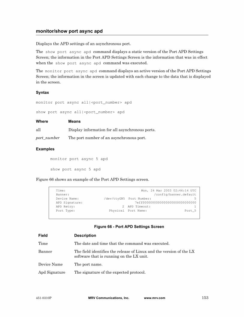
Displays the APD settings of an asynchronous port.
The show port async apd command displays a static version of the Port APD Settings Screen; the information in the Port APD Settings Screen is the information that was in effect when the show port async apd command was executed.
The monitor port async apd command displays an active version of the Port APD Settings Screen; the information in the screen is updated with each change to the data that is displayed in the screen.
Syntax
monitor port async all|<port_number> apd
show port async all|<port_number> apd
Where Means
Examples
monitor port async 5 apd
show port async 5 apd
Figure 66 shows an example of the Port APD Settings screen.
Figure 66 - Port APD Settings Screen
monitor/show port async apd
all Display information for all asynchronous ports.
port_number The port number of an asynchronous port.
Time: Mon, 24 Mar 2003 02:46:14 UTCBanner: /config/banner.defaultDevice Name: /dev/ttyGN5 Port Number: 5APD Signature: 7eff0000000000000000000000000000APD Retry: 2 APD Timeout: 1Port Type: Physical Port Name: Port_5
Field Description
Time The date and time that the command was executed.
Banner The field identifies the release of Linux and the version of the LX software that is running on the LX unit.
Device Name The port name.
Apd Signature The signature of the expected protocol.
451-0310P MRV Communications, Inc. www.mrv.com 153
monitor/show port async apd (continued)
Apd Retry The number of retries that remote hosts can have after they fail to make an APD connection on the first try.
Apd Timeout The length of time, in seconds, that the port can spend in an attempt to determine which protocol is being used to make a connection.
Port Type The port Type. The possible values are Serial, Ethernet, and Virtual.
Port Number The port at which you are logged in.
Port Name The name of the LX port.
154 MRV Communications, Inc. www.mrv.com 451-0310P
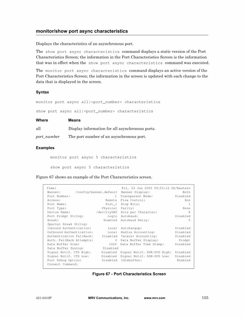
Displays the characteristics of an asynchronous port.
The show port async characteristics command displays a static version of the Port Characteristics Screen; the information in the Port Characteristics Screen is the information that was in effect when the show port async characteristics command was executed.
The monitor port async characteristics command displays an active version of the Port Characteristics Screen; the information in the screen is updated with each change to the data that is displayed in the screen.
Syntax
monitor port async all|<port_number> characteristics
show port async all|<port_number> characteristics
Where Means
Examples
monitor port async 5 characteristics
show port async 5 characteristics
Figure 67 shows an example of the Port Characteristics screen.
Figure 67 - Port Characteristics Screen
monitor/show port async characteristics
all Display information for all asynchronous ports.
port_number The port number of an asynchronous port.
Time: Fri, 24 Jun 2005 09:55:12 US/Eastern Banner: /config/banner.default Banner Display: Both Port Number: 1 Transparent Mode: Disabled Access: Remote Flow Control: Xon Port Name: Port_1 Stop Bits: 1 Port Type: Physical Parity: None Device Name: /dev/ttyGN0 Bits per Character: 8 Port Prompt String: Login Autobaud: Disabled Break: Enabled Autobaud Retry: 5 Special Break String: Inbound Authentication: Local Autohangup: Disabled Outbound Authentication: Local Radius Accounting: Disabled Authentication FallBack: Disabled Tacacs+ Accounting: Disabled Auth. FallBack Attempts: 0 Data Buffer Display: Prompt Data Buffer Size: 1024 Data Buffer Time Stamp: Disabled Data Buffer Syslog: Disabled Signal Notif. CTS High: Disabled Signal Notif. DSR-DCD High: Disabled Signal Notif. CTS Low: Disabled Signal Notif. DSR-DCD Low: Disabled Port Debug Option: Disabled Idlebuffer: Enabled Connect Command:
451-0310P MRV Communications, Inc. www.mrv.com 155
monitor/show port async characteristics (continued)
Field Description
Time The date and time that the show port characteristics command was executed.
Banner The banner file for the port.
Port Number The port at which you are logged in.
Access The type of access the port can have to a service node, and/or the type of access other interactive users and service nodes can have to the port. The possible values are: Dynamic, Local, Remote, Databuffer, Power, Control, or Sensor.
Port Name An ASCII string that is typically used to identify the port that is displayed in this screen.
Port Type The port Type.
Device Name The device name of the port.
Port Prompt String The prompt that is displayed when a user logs in to this port. If this is a custom prompt, this field will contain the custom prompt. If this is the default login prompt, this field will contain “login”.
Break The action the port will take when the user presses the BREAK key. The possible values are Enabled or Disabled.
Special Break String The unique break string for the port.
Inbound Authentication
Indicates whether inbound authentication is Enabled or Disabled on the port.
Outbound Authentication
Indicates whether outbound authentication is Enabled or Disabled on the port.
Authentication Fallback
Indicates whether users can log in by Fallback if the authentication server (RADIUS or TACACS+) is unreachable. The possible settings of this field are Enabled and Disabled.
Auth. Fallback Attempts
The number of attempts made to the primary and secondary server before going to local security. . The default is 3.
Telnet Break String The Telnet Break String for the port.
Telnet Negotiations Indicates whether Telnet Negotiations are Enabled or Disabled.
Telnet CR Filter Indicates the filtering for carriage returns in Telnet sessions.
Telnet Accept Verification
Indicates the state (Enabled or Disabled) of the Telnet Accept Verification Feature.
Telnet Accept Message String
The message that is displayed to the user after a successful connection via Telnet.
156 MRV Communications, Inc. www.mrv.com 451-0310P

monitor/show port async characteristics (continued)
Connect Command The command, or commands, that are executed when a connection to the port is made.
Tcp Window Size The size (in bytes) of the TCP window.
Tcp Transmit Mode The size, in bytes, of the typeahead buffer (the number of bytes or characters that can be temporarily stored pending transmission). A value of “Immediate” indicates a typeahead buffer size of 0.
Banner Display The Banner display option for the port. The possible values are Local, Remote, Both, and None.
Transparent Mode Indicates whether Transparent Mode is Enabled or Disabled on the port.
Flow Control The flow control ("handshaking") method used by the serial interface to control data transfer between the LX port and the device connected to the port. The possible values are XON, CTS, and NONE (disabled). The default value is XON.
Stop Bits The number of stop bits used to maintain synchronization of data. The possible values are 1 or 2.
Parity The method by which the LX unit and the device connected to the port check for single-bit errors in characters transmitted or received by the port. (This is called a parity check because the device provides an extra bit, called a parity bit, for error checking.) The possible values are EVEN, NONE, and ODD, and the default value is NONE.
Bits per Character The number of bits per character for data characters that are transmitted or received over the serial connection between the LX port and the device connected to the port. The possible values are 7 or 8 bits. The default value is 8.
Autobaud Indicates whether Autobaud is enabled or disabled on the port. If Autobaud is enabled, the port will attempt to determine the speed of incoming connections.
Autobaud Retry The number of times that the LX port will attempt to determine the speed of an incoming connection.
Autohangup Indicates whether the port will log out when the last session is terminated. The allowable values are Enabled and Disabled.
RADIUS Accounting Shows the current status of RADIUS accounting. The valid values are Enabled or Disabled.
TACACS+ Accounting
Shows the current status of TACACS+ accounting. The valid values are Enabled or Disabled.
Data Buffer Size The size, in bytes, of the port data buffer.
451-0310P MRV Communications, Inc. www.mrv.com 157

monitor/show port async characteristics (continued)
Data Buffer Display Indicates the state of the Data Buffer Display Feature. The allowable values are Enabled, Disabled, and Prompt.
Data Buffer Syslog Indicates whether the Data Buffer syslog feature is Enabled or Disabled.
Data Buffer Time Stamp
Indicates whether the Data Buffer Timestamp feature is Enabled or Disabled.
Signal Notif. CTS High
Indicates whether the Signal Notif. CTS High feature is Enabled or Disabled.
Signal Notif. CTS Low
Indicates whether the Signal Notif. CTS Low feature is Enabled or Disabled.
Signal Notif. DSR-DCD High
Indicates whether the Signal Notif. DSR-DCD High feature is Enabled or Disabled.
Signal Notif. DSR-DCD Low
Indicates whether the Signal Notif. DSR-DCD Low feature is Enabled or Disabled.
Port Debug Option Indicates whether the Port Debug Feature is Enabled or Disabled.
IdleBuffer Indicates whether the IdleBuffer is Enabled or Disabled
158 MRV Communications, Inc. www.mrv.com 451-0310P

Displays the modem settings for an asynchronous port.
The show port async modem command displays a static version of the Port Modem Settings Screen; the information in the Port Modem Settings Screen is the information that was in effect when the show port async modem command was executed.
The monitor port async modem command displays an active version of the Port Modem Settings Screen; the information in the screen is updated with each change to the data that is displayed in the screen.
Syntax
monitor port async all|<port_number> modem
show port async all|<port_number> modem
Where Means
Examples
monitor port async 7 modem
show port async 7 modem
Figure 68 shows an example of the Port Modem Settings screen.
Figure 68 - Port Modem Settings Screen
monitor/show port async modem
all Display information for all asynchronous ports.
port_number The port number of an asynchronous port.
Time: Mon 24 Mar 2003 12:50:42 UTCBanner: /config/banner.defaultDevice Name: /dev/pts/0 Port Number: 7Port Type: Virtual Port Name: N/AModem Control: Disabled Modem Timeout: 40Modem Retry: 6 Modem Pool: DisabledModem Dialout Num.: 19785558371Modem Init String: AT S7=45 S0=1 L1 V1 X4 &C1 &1 Q0 &S1Modem Type: GSM/GPRSGSM/GPRS: Received Signal Strength: 9GSM/GPRS: Channel Bit Error Rate: 0
Field Description
Time The date and time that the command was executed.
Banner The field identifies the release of Linux and the version of the LX software that is running on the LX unit.
451-0310P MRV Communications, Inc. www.mrv.com 159
monitor/show port async modem (continued)
Device Name The port name.
Port Type The port Type. The possible values are Serial, Ethernet, and Virtual.
Modem Control Shows whether the Modem feature is Enabled or Disabled on this port.
Modem Retry The number of times the LX unit attempts to connect to the remote modem.
Modem Dialout Num.
The telephone number that the modem will dial for a dialout connection.
Modem Init String A configuration string that is sent to the remote modem.
Modem Type Displays the modem type. Options are GSM/GPRS or V.90.
GSM/GPRS Received Signal Strength
The received signal strength of the attached modem. The range is from 0 to 31 (0 being the weakest signal, and 31 the strongest), or 99 (signal not known or not detectable).
GSM/GPRS Channel Bit Error Rate
The channel bit error rate of the attached modem. The range is from 0 to 7 (0 being the lowest error rate, and 7 the highest), or 99 (error rate not known or not detectable).
Port Number The Port Number.
Port Name A text string that typically identifies the modem port.
Modem Timeout The length of time that the remote modem has to respond to the LX unit.
Modem Pool Indicates whether the Modem Pool Feature is Enabled or Disabled for the specified port.
160 MRV Communications, Inc. www.mrv.com 451-0310P
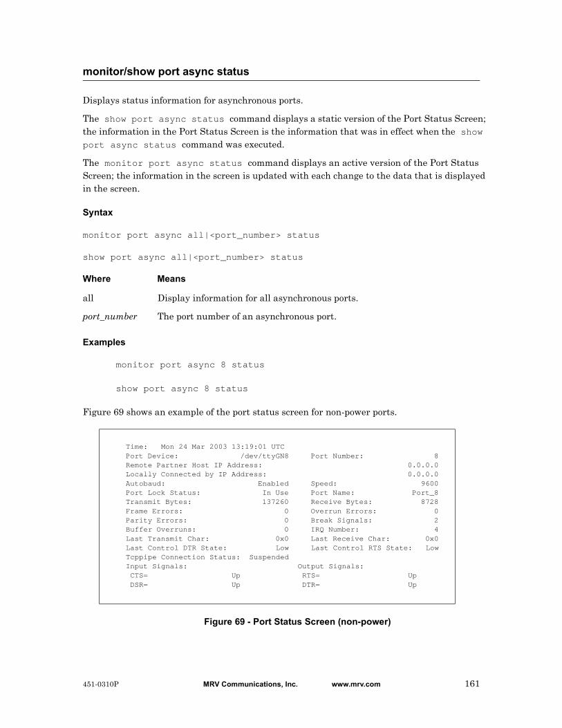
Displays status information for asynchronous ports.
The show port async status command displays a static version of the Port Status Screen; the information in the Port Status Screen is the information that was in effect when the show port async status command was executed.
The monitor port async status command displays an active version of the Port Status Screen; the information in the screen is updated with each change to the data that is displayed in the screen.
Syntax
monitor port async all|<port_number> status
show port async all|<port_number> status
Where Means
Examples
monitor port async 8 status
show port async 8 status
Figure 69 shows an example of the port status screen for non-power ports.
Figure 69 - Port Status Screen (non-power)
monitor/show port async status
all Display information for all asynchronous ports.
port_number The port number of an asynchronous port.
Time: Mon 24 Mar 2003 13:19:01 UTC Port Device: /dev/ttyGN8 Port Number: 8 Remote Partner Host IP Address: 0.0.0.0 Locally Connected by IP Address: 0.0.0.0 Autobaud: Enabled Speed: 9600 Port Lock Status: In Use Port Name: Port_8 Transmit Bytes: 137260 Receive Bytes: 8728 Frame Errors: 0 Overrun Errors: 0 Parity Errors: 0 Break Signals: 2 Buffer Overruns: 0 IRQ Number: 4 Last Transmit Char: 0x0 Last Receive Char: 0x0 Last Control DTR State: Low Last Control RTS State: Low Tcppipe Connection Status: Suspended Input Signals: Output Signals: CTS= Up RTS= Up DSR= Up DTR= Up
451-0310P MRV Communications, Inc. www.mrv.com 161
monitor/show port async status (continued)
Field Description
Port Device The name of the port.
Remote Partner Host IP Address
If the port is connected to a remote host, the IP Address of the remote host appears in this field.
Locally Connected by IP Address
If the port is locally connected to a host, the IP Address of the LX unit, or the rotary address for the port, appears in this field.
Autobaud Indicates whether Autobaud is enabled or disabled on the port. If Autobaud is enabled, the port will attempt to determine the speed of incoming connections.
Port Lock Status Indicates whether or not the port is locked.
Transmit Bytes The number of bytes transmitted on the port since the counters were last reset to zero.
Frame Errors The number of bytes received at the port with illegally formatted frames, since the counter was reset to zero. Frequent framing errors (more than 20 per day for a terminal; 200 per day for a modem) may indicate a problem with the port or the device attached to the port, or mismatched settings between the port and the data received from the attached serial device.
Parity Errors The number of bytes received at the port with parity errors, since the counters were reset to zero. Frequent parity errors (more than 20 per day for a terminal; 200 per day for a modem, due to line noise) may indicate a problem with the port or the device attached to the port, or mismatched settings between the port and the device connected to the port.
Buffer Overruns The number of times characters were lost because the LX unit input buffers were full, since the counters were reset to zero. Buffer overruns indicate that there may be a flow control problem, such as mismatched flow control methods, between the port and the device connected to the port.
Last Transmit Char The last character transmitted on the port.
Last Control DTR State
The last state (High or Low) to which the port DTR signal was set. (Note: This field only contains a value for CONTROL access ports.)
162 MRV Communications, Inc. www.mrv.com 451-0310P
monitor/show port async status (continued)
Tcppipe Connection Status
Displays the current tcppipe connection status. The options are:
Idle - When autohangup is enabled on the source tcppipe port and DSR is down.
Connecting - The tcppipe source async port is trying to connect to the peer.
Connected - The tcppipe source async port has made a successful tcp connection to the peer.
Suspended - The tcppipe source async port has exhausted all of the tcppipe retries to no avail.
This field appears only when access on the port is set to tcppipe.
Input Signals The status of the port CTS and DSR signals.
Port Number The port number of the asynchronous port.
Time The day, date, and time of the LX system clock.
Speed The port speed.
Port Name The name of the asynchronous port.
Receive Bytes The number of bytes received on the port since the counters were last reset to zero.
Overrun Errors The number of port overrun errors since the counters were last reset to zero.
Break Signals The number of break signals entering this Local Access port from the connected device since the counters were last reset to zero.
IRQ Number The IRQ Number for the port.
Last Receive Char The last character received on the port.
Last Control RTS State
The last state (High or Low) to which the port RTS signal was set. (Note: This field only contains a value for CONTROL access ports.)
Output Signals The status of the port RTS and DTR signals.
451-0310P MRV Communications, Inc. www.mrv.com 163

Figure 70 shows an example of the port status screen for power ports.
Figure 70 - Port Status Screen (Power)
monitor/show port async status (continued)
Time: 29 Mar 2005 12:24:46 US/EASTERN Device Number: 39 Device Type: IR4800 Model Name: Firmware: Sentry Version 5.3a (Beta 8) Total Outlet Strip Current Load: 1.50 Total Outlet Strip % Current Utilization(%): N/A Outlet Minimum Off Time: 11 Power Boot Sequence: Enabled Power Cli: Disabled Power SCP Authentication: Disabled SCP Admin name: Not configured SCP Admin password: Not configured Power Factory Reset Button: Enabled
Enclosure 1: Status: Normal Input A: Control Status: On Load: N/A Outlet Name State Status Boot Wakeup Load Off 1 IR4800OutletAA1 On On 0 Off 0.0 Amps Enabled Groups: 2,4,5,7,9,11,13,15,17,19,21,23,25,27,29,31,33,35,37,39,41,43,45,47, 49,51,53,55,57,59,61,63,65,67,69,71,73,75,77,79,81,83,85,87,89,91,93,95,97,99 2 IR4800OutletAB1 On On 1 Off 0.5 Amps Enabled Groups: 2,4,6,8,10,12,14,16,18,20,22,24,26,28,30,32,34,36,38,40,42,44,46,48, 50,52,54,56,58,60,62,64,66,68,70,72,74,76,78,80,82,84,86,88,90,92,94,96,98
Input B: Control Status: On Load: N/A Outlet Name State Status Boot Wakeup Load Off 3 IR4800OutletAA2 On On 2 Off 0.5 Amps Enabled Groups: 1,4 4 IR4800OutletAB2 On On 3 Off 0.5 Amps Enabled Groups: 4
Field Description
Device Type Identifies the type of Power Control unit.
Model Name The Model Name of the Power Control unit.
Firmware The firmware version running on the Power Control unit.
Total Outlet Strip Current Load
The total load for the Power Control unit.
Total Outlet Strip % Current Utilization
The percentage of the Power Outlet strip being used.
Outlet Minimum Off Time
The minimum time that outlets in this Power Control unit must remain off after they are turned off with the outlet or outlet group command.
Outlet The Outlet Number of an outlet.
Name The descriptive name of an outlet.
State The ON or OFF state of the outlet.
164 MRV Communications, Inc. www.mrv.com 451-0310P
monitor/show port async status (continued)
Status The status of the outlet (On or Off).
Boot The boot state of the outlet.
Wakeup The wakeup state (On or Off).
Load The load on the outlet.
Off The off state (Enabled or Disabled).
Assigned Groups The outlet groups to which the outlet is assigned.
451-0310P MRV Communications, Inc. www.mrv.com 165
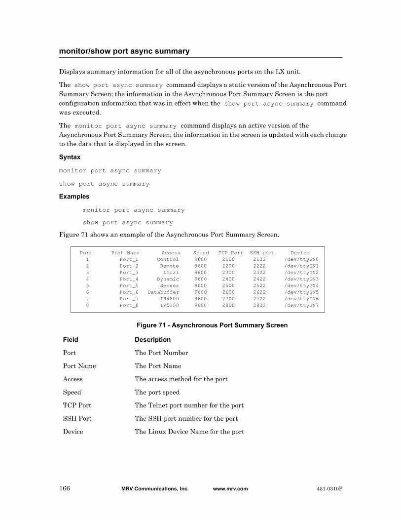
Displays summary information for all of the asynchronous ports on the LX unit.
The show port async summary command displays a static version of the Asynchronous Port Summary Screen; the information in the Asynchronous Port Summary Screen is the port configuration information that was in effect when the show port async summary command was executed.
The monitor port async summary command displays an active version of the Asynchronous Port Summary Screen; the information in the screen is updated with each change to the data that is displayed in the screen.
Syntax
monitor port async summary
show port async summary
Examples
monitor port async summary
show port async summary
Figure 71 shows an example of the Asynchronous Port Summary Screen.
Figure 71 - Asynchronous Port Summary Screen
monitor/show port async summary
Port Port Name Access Speed TCP Port SSH port Device 1 Port_1 Control 9600 2100 2122 /dev/ttyGN0 2 Port_2 Remote 9600 2200 2222 /dev/ttyGN1 3 Port_3 Local 9600 2300 2322 /dev/ttyGN2 4 Port_4 Dynamic 9600 2400 2422 /dev/ttyGN3 5 Port_5 Sensor 9600 2500 2522 /dev/ttyGN4 6 Port_6 Databuffer 9600 2600 2622 /dev/ttyGN5 7 Port_7 IR4800 9600 2700 2722 /dev/ttyGN6 8 Port_8 IR5150 9600 2800 2822 /dev/ttyGN7
Field Description
Port The Port Number
Port Name The Port Name
Access The access method for the port
Speed The port speed
TCP Port The Telnet port number for the port
SSH Port The SSH port number for the port
Device The Linux Device Name for the port
166 MRV Communications, Inc. www.mrv.com 451-0310P
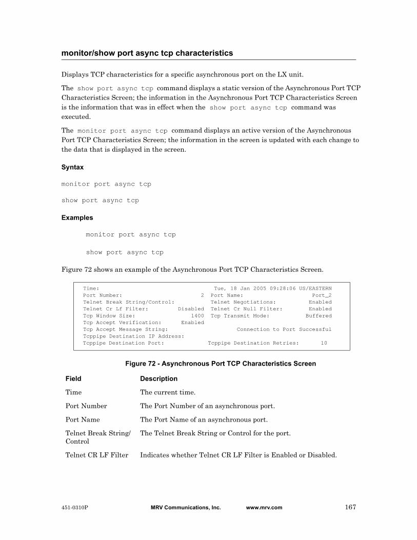
Displays TCP characteristics for a specific asynchronous port on the LX unit.
The show port async tcp command displays a static version of the Asynchronous Port TCP Characteristics Screen; the information in the Asynchronous Port TCP Characteristics Screen is the information that was in effect when the show port async tcp command was executed.
The monitor port async tcp command displays an active version of the Asynchronous Port TCP Characteristics Screen; the information in the screen is updated with each change to the data that is displayed in the screen.
Syntax
monitor port async tcp
show port async tcp
Examples
monitor port async tcp
show port async tcp
Figure 72 shows an example of the Asynchronous Port TCP Characteristics Screen.
Figure 72 - Asynchronous Port TCP Characteristics Screen
monitor/show port async tcp characteristics
Time: Tue, 18 Jan 2005 09:28:06 US/EASTERN Port Number: 2 Port Name: Port_2 Telnet Break String/Control: Telnet Negotiations: Enabled Telnet Cr Lf Filter: Disabled Telnet Cr Null Filter: Enabled Tcp Window Size: 1400 Tcp Transmit Mode: Buffered Tcp Accept Verification: Enabled Tcp Accept Message String: Connection to Port Successful Tcppipe Destination IP Address: Tcppipe Destination Port: Tcppipe Destination Retries: 10
Field Description
Time The current time.
Port Number The Port Number of an asynchronous port.
Port Name The Port Name of an asynchronous port.
Telnet Break String/Control
The Telnet Break String or Control for the port.
Telnet CR LF Filter Indicates whether Telnet CR LF Filter is Enabled or Disabled.
451-0310P MRV Communications, Inc. www.mrv.com 167
monitor/show port async tcp characteristics (continued)
Telnet CR Null Filter
Indicates whether Telnet CR Null Filter is Enabled or Disabled.
Telnet Negotiations Indicates whether Telnet Negotiations are Enabled or Disabled.
Telnet Accept Verification
Indicates the state (Enabled or Disabled) of the Telnet Accept Verification Feature.
Telnet Cr Filter Indicates the filtering for carriage returns in Telnet sessions.
Tcp Accept Message String
The message that is displayed to the user after a successful connection via Telnet or SSH.
Tcp Window Size The size (in bytes) of the TCP window.
Tcp Transmit Mode The size, in bytes, of the typeahead buffer (the number of bytes or characters that can be temporarily stored pending transmission). A value of “Immediate” indicates a typeahead buffer size of 0.
Tcp Destination IP Address
The TCP destination IP address that will connect to the port (when configured as TCP pipe).
Tcp Destination Port The port that will connect to the tcp destination address TCP port (when configured as TCP pipe).
Tcppipe Destination Retries
The number of times the LX attempts to reach the TCP destination. The range is 0-60. The default is 10. Entering 0 causes the LX to try to connect indefinitely.
168 MRV Communications, Inc. www.mrv.com 451-0310P

Displays the Port Type and Banner Filename for the port at which you are logged on.
The show port characteristics command displays a static version of the Logged-in Port Characteristics Screen; the information in the Logged-in Port Characteristics Screen is the information that was in effect when the show port characteristics command was executed.
The monitor port characteristics command displays an active version of the Logged-in Port Characteristics Screen; the information in the screen is updated with each change to the data that is displayed in the screen.
Syntax
monitor port characteristics
show port characteristics
Examples
monitor port characteristics
show port characteristics
Figure 71 shows an example of the Logged-in Port Characteristics Screen.
Figure 73 - Logged-in Port Characteristics Screen
monitor/show port characteristics
Time: Tue, 27 May 2003 23:04:44 UTC Banner: /config/banner.default Port Type: Virtual
Field Description
Time The date and time that the monitor/show port characteristics command was executed.
Banner The file that contains the Login Banner for the port.
Port Type The Port Type
451-0310P MRV Communications, Inc. www.mrv.com 169

Displays the characteristics of an Ethernet port.
The show port ethernet characteristics command displays a static version of the Ethernet Port Characteristics Screen; the information in the Ethernet Port Characteristics Screen is the information that was in effect when the show port ethernet characteristics command was executed.
The monitor port ethernet characteristics command displays an active version of the Ethernet Port Characteristics Screen; the information in the screen is updated with each change to the data that is displayed in the screen.
Syntax
monitor port ethernet all|<port_number> characteristics
show port ethernet all|<port_number> characteristics
Where Means
Examples
monitor port ethernet 1 characteristics
show port ethernet 1 characteristics
Figure 74 shows an example of the Ethernet Port Characteristics Screen.
Figure 74 - Ethernet Port Characteristics Screen
monitor/show port ethernet characteristics
all Display information for all Ethernet ports.
port_number The port number of an Ethernet port.
Time: Mon, 24 Mar 2003 22:30:19Name: eth0 MAC Address: 00:a0:87:9c:00:50:e3Link Speed: Auto Duplex Mode: AutoDescription:
Field Description
Name The name of the port.
Description The description of the Ethernet port.
MAC Address The Ethernet MAC Address for the port.
Link Speed The Ethernet port speed. The possible values are auto, 10mb and 100mb.
Duplex Mode The duplex mode of the Ethernet port. The possible values are auto, full, and half.
170 MRV Communications, Inc. www.mrv.com 451-0310P
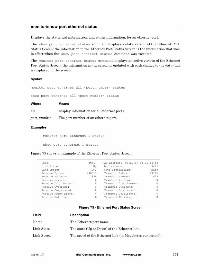
Displays the statistical information, and status information, for an ethernet port.
The show port ethernet status command displays a static version of the Ethernet Port Status Screen; the information in the Ethernet Port Status Screen is the information that was in effect when the show port ethernet status command was executed.
The monitor port ethernet status command displays an active version of the Ethernet Port Status Screen; the information in the screen is updated with each change to the data that is displayed in the screen.
Syntax
monitor port ethernet all|<port_number> status
show port ethernet all|<port_number> status
Where Means
Examples
monitor port ethernet 1 status
show port ethernet 1 status
Figure 75 shows an example of the Ethernet Port Status Screen.
Figure 75 - Ethernet Port Status Screen
monitor/show port ethernet status
all Display information for all ethernet ports.
port_number The port number of an ethernet port.
Name: eth0 MAC Address: 00:a0:87:9c:00:50:e3 Link State: Up Duplex Mode: Half Link Speed: 100 Auto Negotiation: Auto Receive Bytes: 240061 Transmit Bytes: 40115 Receive Packets: 2890 Transmit Packets: 659 Receive Errors: 0 Transmit Errors: 0 Receive Drop Packet: 0 Transmit Drop Packet: 0 Receive Overruns: 0 Transmit Overruns: 0 Receive Compressed: 0 Transmit Compressed: 0 Receive Frame Error: 0 Transmit Collisions: 0 Receive Multicast: 0 Transmit Carrier: 0
Field Description
Name The Ethernet port name.
Link State The state (Up or Down) of the Ethernet link.
Link Speed The speed of the Ethernet link (in Megabytes per second).
451-0310P MRV Communications, Inc. www.mrv.com 171
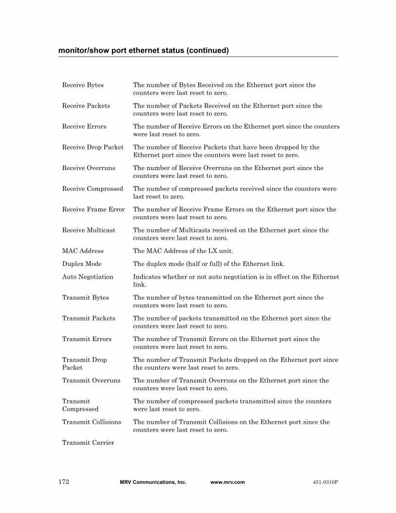
monitor/show port ethernet status (continued)
Receive Bytes The number of Bytes Received on the Ethernet port since the counters were last reset to zero.
Receive Packets The number of Packets Received on the Ethernet port since the counters were last reset to zero.
Receive Errors The number of Receive Errors on the Ethernet port since the counters were last reset to zero.
Receive Drop Packet The number of Receive Packets that have been dropped by the Ethernet port since the counters were last reset to zero.
Receive Overruns The number of Receive Overruns on the Ethernet port since the counters were last reset to zero.
Receive Compressed The number of compressed packets received since the counters were last reset to zero.
Receive Frame Error The number of Receive Frame Errors on the Ethernet port since the counters were last reset to zero.
Receive Multicast The number of Multicasts received on the Ethernet port since the counters were last reset to zero.
MAC Address The MAC Address of the LX unit.
Duplex Mode The duplex mode (half or full) of the Ethernet link.
Auto Negotiation Indicates whether or not auto negotiation is in effect on the Ethernet link.
Transmit Bytes The number of bytes transmitted on the Ethernet port since the counters were last reset to zero.
Transmit Packets The number of packets transmitted on the Ethernet port since the counters were last reset to zero.
Transmit Errors The number of Transmit Errors on the Ethernet port since the counters were last reset to zero.
Transmit Drop Packet
The number of Transmit Packets dropped on the Ethernet port since the counters were last reset to zero.
Transmit Overruns The number of Transmit Overruns on the Ethernet port since the counters were last reset to zero.
Transmit Compressed
The number of compressed packets transmitted since the counters were last reset to zero.
Transmit Collisions The number of Transmit Collisions on the Ethernet port since the counters were last reset to zero.
Transmit Carrier
172 MRV Communications, Inc. www.mrv.com 451-0310P

Displays summary information for the Ethernet ports on the LX unit.
The show port ethernet summary command displays a static version of the Ethernet Port Summary Screen; the information in the Ethernet Port Summary Screen is the information that was in effect when the show port ethernet summary command was executed.
The monitor port ethernet summary command displays an active version of the Ethernet Port Summary Screen; the information in the screen is updated with each change to the data that is displayed in the screen.
Syntax
monitor port ethernet summary
show port ethernet summary
Examples
monitor port ethernet summary
show port ethernet summary
Figure 76 shows an example of the Ethernet Port Summary Screen.
Figure 76 - Ethernet Port Summary Screen
monitor/show port ethernet summary
Name MAC-Address eth0 00:a0:87:9c:00:50:e3
Field Description
Name The name of the Ethernet port.
MAC Address The MAC (physical) Address of the Ethernet port.
451-0310P MRV Communications, Inc. www.mrv.com 173

Displays modem characteristics for the port at which you are currently logged in.
NOTE: In order for this command to display data, you must be logged in via a modem port.
The show port modem command displays a static version of the Logged-in Port Modem Screen; the information in the Logged-in Port Modem Screen is the information that was in effect when the show port modem command was executed.
The monitor port modem command displays an active version of the Logged-in Port Modem Screen; the information in the screen is updated with each change to the data that is displayed in the screen.
Syntax
monitor port modem
show port modem
Examples
monitor port modem
show port modem
The Logged-in Port Modem Screen is identical to the Port Modem Settings Screen. Figure 68 on page 159 contains an example of the Port Modem Settings Screen.
monitor/show port modem
174 MRV Communications, Inc. www.mrv.com 451-0310P
Displays status information for the port at which you are currently logged in.
NOTE: You cannot execute this command while you are logged in at a virtual port.
The show port status command displays a static version of the Logged-in Port Status Screen; the information in the Logged-in Port Status Screen is the information that was in effect when the show port status command was executed.
The monitor port status command displays an active version of the Logged-in Port Status Screen; the information in the screen is updated with each change to the data that is displayed in the screen.
Syntax
monitor port status
show port status
Examples
monitor port status
show port status
The Logged-in Port Status Screen is identical to the Port Status Screen. Figure 69 on page 161 contains an example of the Port Status Screen for non-power ports. Figure 70 on page 164 contains an example of the Port Status Screen for power ports.
monitor/show port status
451-0310P MRV Communications, Inc. www.mrv.com 175
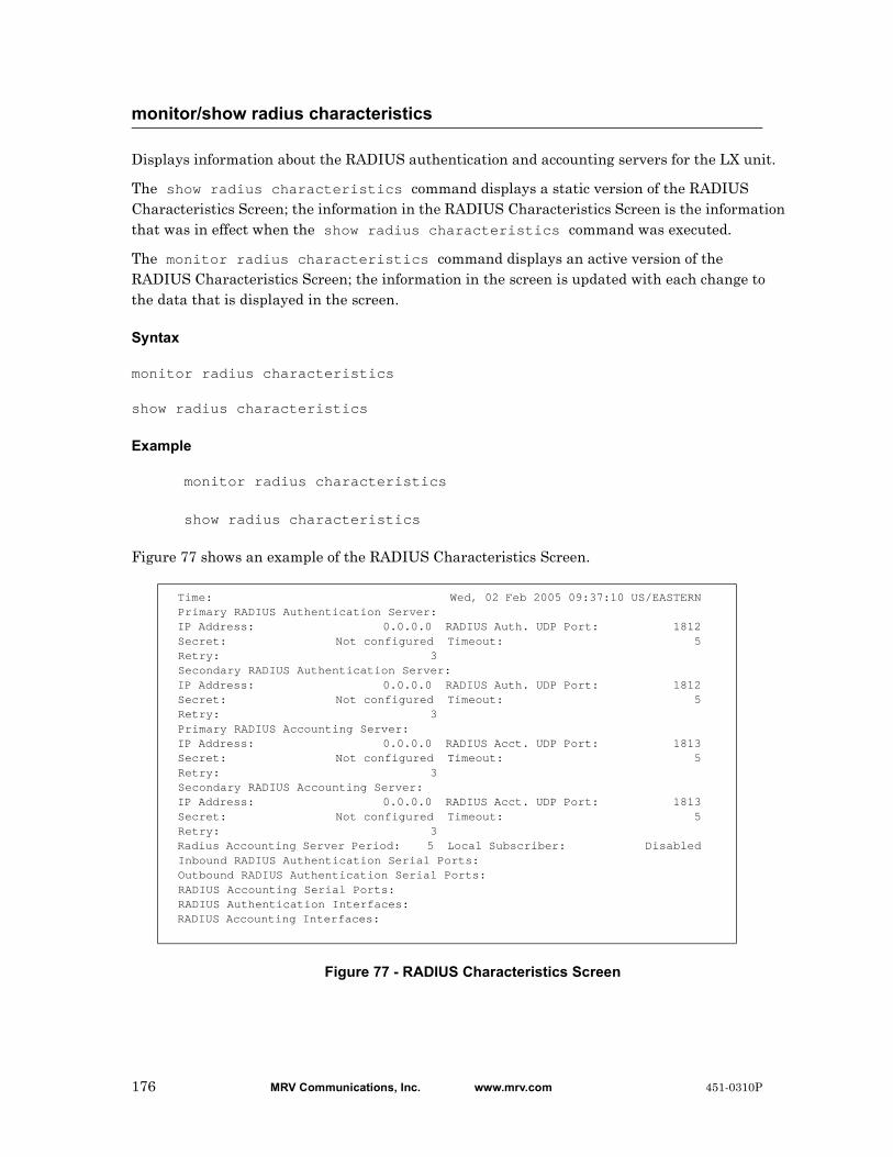
Displays information about the RADIUS authentication and accounting servers for the LX unit.
The show radius characteristics command displays a static version of the RADIUS Characteristics Screen; the information in the RADIUS Characteristics Screen is the information that was in effect when the show radius characteristics command was executed.
The monitor radius characteristics command displays an active version of the RADIUS Characteristics Screen; the information in the screen is updated with each change to the data that is displayed in the screen.
Syntax
monitor radius characteristics
show radius characteristics
Example
monitor radius characteristics
show radius characteristics
Figure 77 shows an example of the RADIUS Characteristics Screen.
Figure 77 - RADIUS Characteristics Screen
monitor/show radius characteristics
Time: Wed, 02 Feb 2005 09:37:10 US/EASTERN Primary RADIUS Authentication Server: IP Address: 0.0.0.0 RADIUS Auth. UDP Port: 1812 Secret: Not configured Timeout: 5 Retry: 3 Secondary RADIUS Authentication Server: IP Address: 0.0.0.0 RADIUS Auth. UDP Port: 1812 Secret: Not configured Timeout: 5 Retry: 3 Primary RADIUS Accounting Server: IP Address: 0.0.0.0 RADIUS Acct. UDP Port: 1813 Secret: Not configured Timeout: 5 Retry: 3 Secondary RADIUS Accounting Server: IP Address: 0.0.0.0 RADIUS Acct. UDP Port: 1813 Secret: Not configured Timeout: 5 Retry: 3 Radius Accounting Server Period: 5 Local Subscriber: Disabled Inbound RADIUS Authentication Serial Ports: Outbound RADIUS Authentication Serial Ports: RADIUS Accounting Serial Ports: RADIUS Authentication Interfaces: RADIUS Accounting Interfaces:
176 MRV Communications, Inc. www.mrv.com 451-0310P
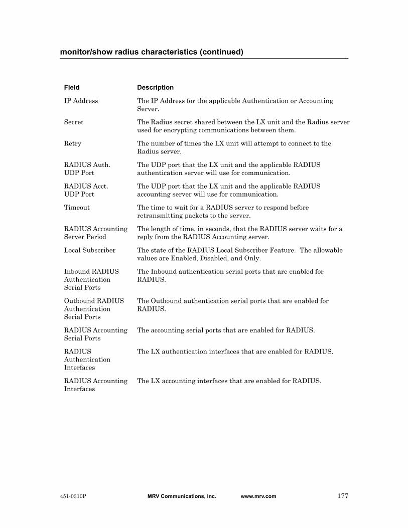
monitor/show radius characteristics (continued)
Field Description
IP Address The IP Address for the applicable Authentication or Accounting Server.
Secret The Radius secret shared between the LX unit and the Radius server used for encrypting communications between them.
Retry The number of times the LX unit will attempt to connect to the Radius server.
RADIUS Auth. UDP Port
The UDP port that the LX unit and the applicable RADIUS authentication server will use for communication.
RADIUS Acct. UDP Port
The UDP port that the LX unit and the applicable RADIUS accounting server will use for communication.
Timeout The time to wait for a RADIUS server to respond before retransmitting packets to the server.
RADIUS Accounting Server Period
The length of time, in seconds, that the RADIUS server waits for a reply from the RADIUS Accounting server.
Local Subscriber The state of the RADIUS Local Subscriber Feature. The allowable values are Enabled, Disabled, and Only.
Inbound RADIUS Authentication Serial Ports
The Inbound authentication serial ports that are enabled for RADIUS.
Outbound RADIUS Authentication Serial Ports
The Outbound authentication serial ports that are enabled for RADIUS.
RADIUS Accounting Serial Ports
The accounting serial ports that are enabled for RADIUS.
RADIUS Authentication Interfaces
The LX authentication interfaces that are enabled for RADIUS.
RADIUS Accounting Interfaces
The LX accounting interfaces that are enabled for RADIUS.
451-0310P MRV Communications, Inc. www.mrv.com 177

Displays statistical information on RADIUS authentication attempts.
The show radius status command displays a static version of the RADIUS Status Screen; the information in the RADIUS Status Screen is the information that was in effect when the show radius status command was executed.
The monitor radius status command displays an active version of the RADIUS Status Screen; the information in the screen is updated with each change to the data that is displayed in the screen.
Syntax
monitor radius status
show radius status
Examples
monitor radius status
show radius status
Figure 78 shows an example of the RADIUS Status Screen.
Figure 78 - RADIUS Status Screen
monitor/show radius status
Time: Wed, 08 May 2002 13:32:34 UTCTotal RADIUS Authentication Message Exchange: Primary Secondary Successful attempts: 2 0 Failed attempts: 0 0
Total RADIUS Accounting Message Exchange: Primary Secondary Successful attempts: 0 0 Failed attempts: 6 6
RADIUS Authentication Counter Summary: Primary Secondary Successful Logins: 2 0 Authentication Failures: 0 0 Configuration Failures: 0 0 Policy Failures: 0 0
RADIUS Accounting Counter Summary: Primary Secondary Successful Acct Entries: 0 0 Failed Acct Entries: 0 0 Requests Waiting: 0 0
RADIUS Fallback Counter Summary: Total Fallback Logins: 0
178 MRV Communications, Inc. www.mrv.com 451-0310P
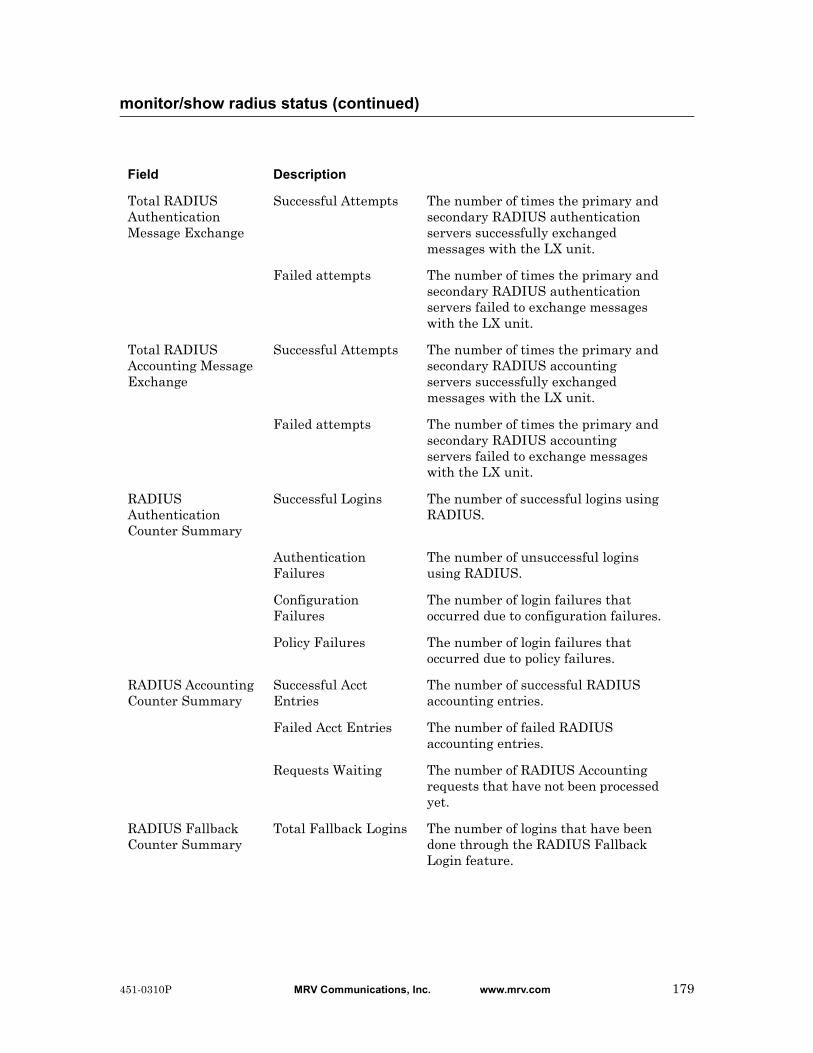
monitor/show radius status (continued)
Field Description
Total RADIUS Authentication Message Exchange
Successful Attempts The number of times the primary and secondary RADIUS authentication servers successfully exchanged messages with the LX unit.
Failed attempts The number of times the primary and secondary RADIUS authentication servers failed to exchange messages with the LX unit.
Total RADIUS Accounting Message Exchange
Successful Attempts The number of times the primary and secondary RADIUS accounting servers successfully exchanged messages with the LX unit.
Failed attempts The number of times the primary and secondary RADIUS accounting servers failed to exchange messages with the LX unit.
RADIUS Authentication Counter Summary
Successful Logins The number of successful logins using RADIUS.
Authentication Failures
The number of unsuccessful logins using RADIUS.
Configuration Failures
The number of login failures that occurred due to configuration failures.
Policy Failures The number of login failures that occurred due to policy failures.
RADIUS Accounting Counter Summary
Successful Acct Entries
The number of successful RADIUS accounting entries.
Failed Acct Entries The number of failed RADIUS accounting entries.
Requests Waiting The number of RADIUS Accounting requests that have not been processed yet.
RADIUS Fallback Counter Summary
Total Fallback Logins The number of logins that have been done through the RADIUS Fallback Login feature.
451-0310P MRV Communications, Inc. www.mrv.com 179

Displays summary data for the RADIUS authentication and accounting servers.
The show radius summary command displays a static version of the RADIUS Summary Screen; the information in the RADIUS Summary Screen is the information that was in effect when the show radius summary command was executed.
The monitor radius summary command displays an active version of the RADIUS Summary Screen; the information in the screen is updated with each change to the data that is displayed in the screen.
Syntax
monitor radius summary
show radius summary
Example
monitor radius summary
show radius summary
Figure 79 shows an example of the RADIUS Summary Screen.
Figure 79 - RADIUS Summary Screen
monitor/show radius summary
Radius Server Summary Thu, 12 Sep 2002 20:47:18 Primary Auth. Server: 0.0.0.0 Primary Auth. UDP Port: 1812 Secondary Auth. Server: 0.0.0.0 Secondary Auth. UDP Port: 1812 Primary Acct. Server: 0.0.0.0 Primary Acct. UDP Port: 1813 Secondary Acct. Server: 0.0.0.0 Secondary Acct. UDP Port: 1813
Field Description
Primary Auth. Server
The IP Address of the Primary RADIUS Authentication server.
Secondary Auth. Server
The IP Address of the Secondary RADIUS Authentication server.
Primary Acct. Server
The IP Address of the Primary RADIUS Accounting server.
Secondary Acct. Server
The IP Address of the Secondary RADIUS Accounting server.
Primary Auth. UDP Port
The UDP port for the Primary RADIUS Authentication server.
180 MRV Communications, Inc. www.mrv.com 451-0310P
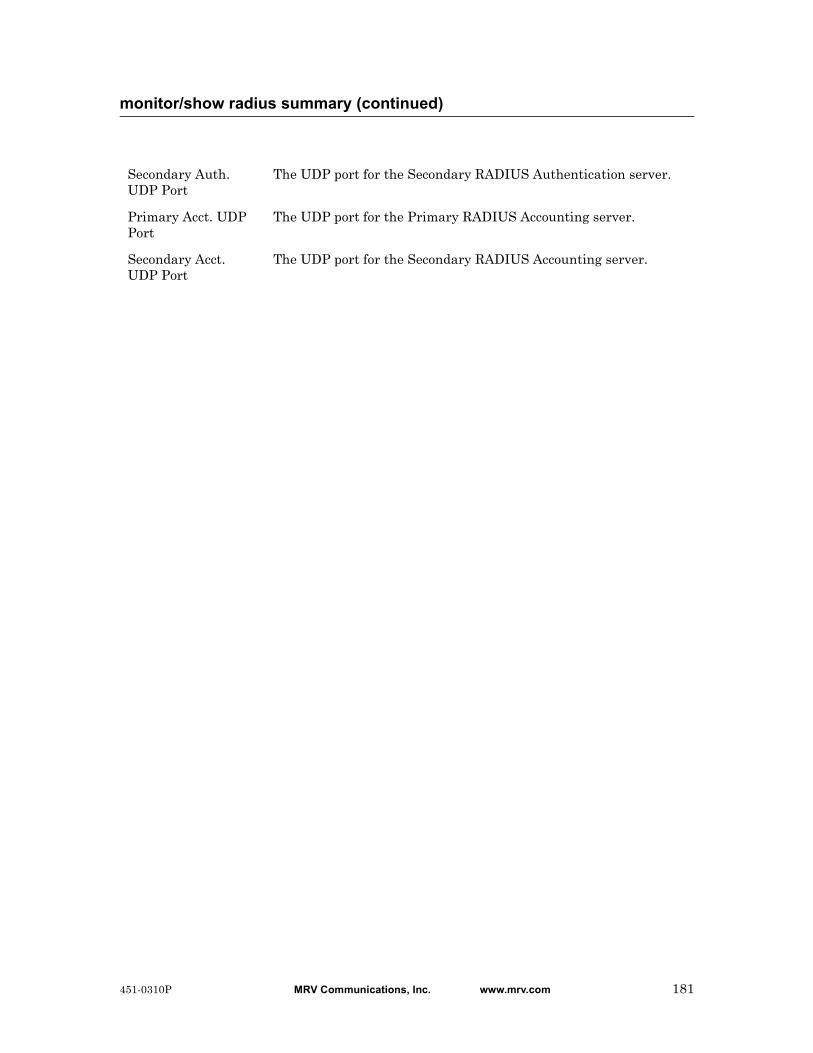
monitor/show radius summary (continued)
Secondary Auth. UDP Port
The UDP port for the Secondary RADIUS Authentication server.
Primary Acct. UDP Port
The UDP port for the Primary RADIUS Accounting server.
Secondary Acct. UDP Port
The UDP port for the Secondary RADIUS Accounting server.
451-0310P MRV Communications, Inc. www.mrv.com 181

Displays the IP addresses of the each route, along with the subnet mask, gateway, and IP interface associated with the each active route.
The show route command displays information on the active routes that existed at the time the command was executed; the information in the Route Screen is the information that was in effect when the show route command was executed.
The monitor route command displays a continuously updating list of routes.
Syntax
monitor route [static]
show route [static]
Where Means
Examples
monitor route
show route
monitor route static
show route static
Figure 80 shows an example of the Route Screen.
Figure 80 - Route Screen
monitor/show route
static Display information for static routes only.
Note: When you use this option, the Route Screen does not show an IP interface for the route.
Route Mask Gateway If140.179.169.0 255.255.255.0 0.0.0.0 eth0 0.0.0.0 0.0.0.0 140.179.169.1 eth0
182 MRV Communications, Inc. www.mrv.com 451-0310P

Displays information about the SecurID authentication server for the LX unit.
The show securid characteristics command displays a static version of the SecurID Characteristics Screen; the information in the SecurID Characteristics Screen is the information that was in effect when the show securid characteristics command was executed.
The monitor securid characteristics command displays an active version of the SecurID Characteristics Screen; the information in the screen is updated with each change to the data that is displayed in the screen.
Syntax
monitor securid characteristics
show securid characteristics
Examples
monitor securid characteristics
show securid characteristics
Figure 77 shows an example of the SecurID Characteristics Screen.
Figure 81 - SecurID Characteristics Screen
monitor/show securid characteristics
Time: Mon, 17 Mar 2003 18:09:34 UTCSecurID Configuration Settings Authentication Version: Version_5 Authentication Encryption: DES Authentication Timeout: 5 Authentication Retransmit: 3 Authentication Port: 5500 V5 Primary Server: 0.0.0.0 Primary Name: Legacy Master Server: 0.0.0.0 Master Name: Legacy Slave Server: 0.0.0.0 Slave Name: Local Subscriber: Disabled Inbound SecurID Enabled Serial Ports: Outbound SecurID Enabled Serial Ports: SecurID Enabled Interfaces:
Field Description
Time The date and time that the show securid characteristics command was executed.
Authentication Version
The version of SecurID that is running on the SecurID authentication server. The possible values are Legacy and Version_5.
Authentication Timeout
The time to wait for the SecurID authentication server to respond before retransmitting packets to the server.
451-0310P MRV Communications, Inc. www.mrv.com 183
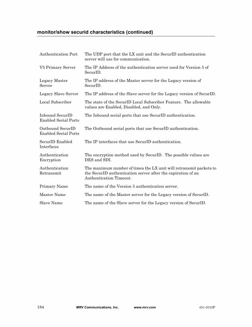
monitor/show securid characteristics (continued)
Authentication Port The UDP port that the LX unit and the SecurID authentication server will use for communication.
V5 Primary Server The IP Address of the authentication server used for Version 5 of SecurID.
Legacy Master Server
The IP address of the Master server for the Legacy version of SecurID.
Legacy Slave Server The IP address of the Slave server for the Legacy version of SecurID.
Local Subscriber The state of the SecurID Local Subscriber Feature. The allowable values are Enabled, Disabled, and Only.
Inbound SecurID Enabled Serial Ports
The Inbound serial ports that use SecurID authentication.
Outbound SecurID Enabled Serial Ports
The Outbound serial ports that use SecurID authentication.
SecurID Enabled Interfaces
The IP interfaces that use SecurID authentication.
Authentication Encryption
The encryption method used by SecurID. The possible values are DES and SDI.
Authentication Retransmit
The maximum number of times the LX unit will retransmit packets to the SecurID authentication server after the expiration of an Authentication Timeout.
Primary Name The name of the Version 5 authentication server.
Master Name The name of the Master server for the Legacy version of SecurID.
Slave Name The name of the Slave server for the Legacy version of SecurID.
184 MRV Communications, Inc. www.mrv.com 451-0310P

Displays statistical information on SecurID authentication attempts.
The show securid status command displays a static version of the SecurID Status Screen; the information in the SecurID Status Screen is the information that was in effect when the show securid status command was executed.
The monitor securid status command displays an active version of the SecurID Status Screen; the information in the screen is updated with each change to the data that is displayed in the screen.
Syntax
monitor securid status
show securid status
Examples
monitor securid status
show securid status
Figure 78 shows an example of the SecurID Status Screen.
Figure 82 - SecurID Status Screen
monitor/show securid status
Time: Mon, 24 Feb 2003 16:55:59SecurID Status & Counters:Successful Logins: 0Failed Logins: 0Fallback Logins: 0Learned SecurID Node Secret: FalseLearned SecurID Servers:
Field Description
Time The date and time that the show securid status command was executed.
Successful Logins The number of successful logins using SecurID.
Failed Logins The number of unsuccessful logins using SecurID.
Fallback Logins The number of logins that have been accomplished using SecurID Fallback.
451-0310P MRV Communications, Inc. www.mrv.com 185
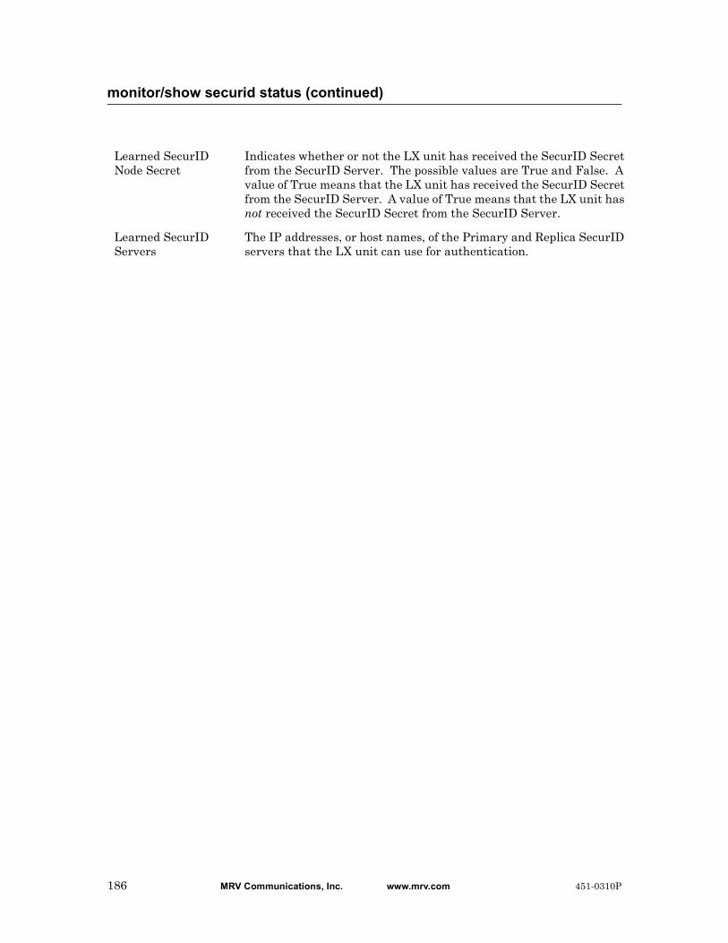
monitor/show securid status (continued)
Learned SecurID Node Secret
Indicates whether or not the LX unit has received the SecurID Secret from the SecurID Server. The possible values are True and False. A value of True means that the LX unit has received the SecurID Secret from the SecurID Server. A value of True means that the LX unit has not received the SecurID Secret from the SecurID Server.
Learned SecurID Servers
The IP addresses, or host names, of the Primary and Replica SecurID servers that the LX unit can use for authentication.
186 MRV Communications, Inc. www.mrv.com 451-0310P
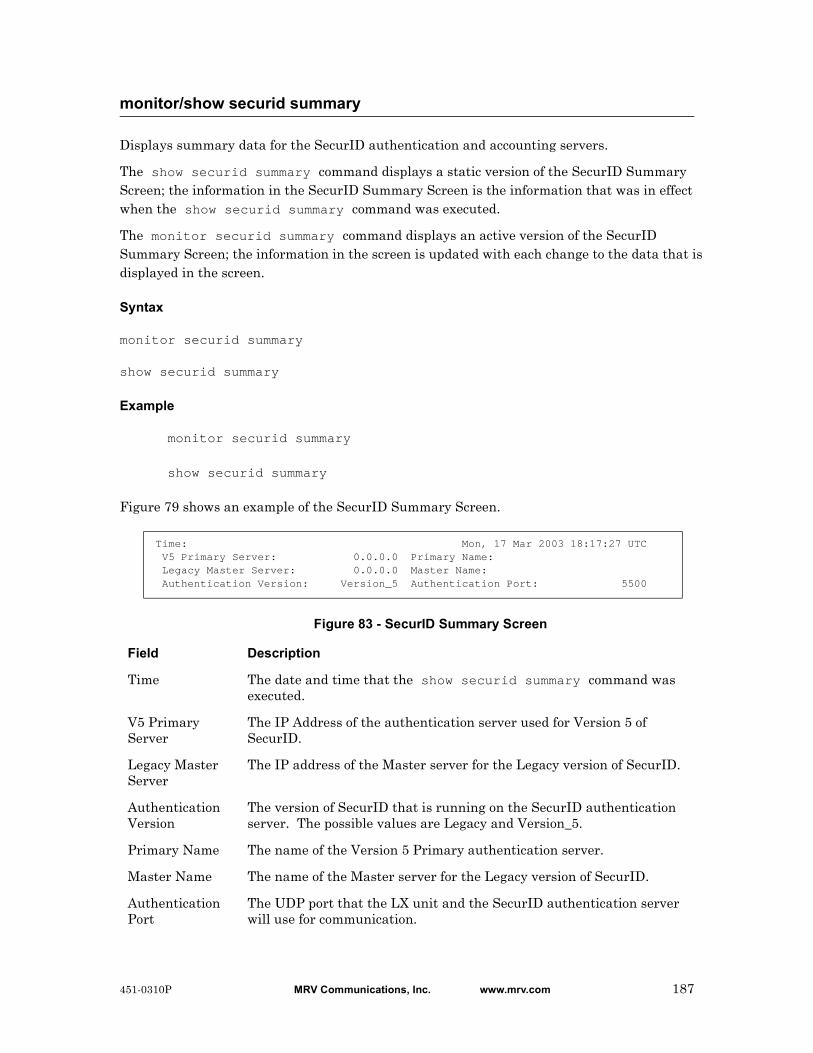
Displays summary data for the SecurID authentication and accounting servers.
The show securid summary command displays a static version of the SecurID Summary Screen; the information in the SecurID Summary Screen is the information that was in effect when the show securid summary command was executed.
The monitor securid summary command displays an active version of the SecurID Summary Screen; the information in the screen is updated with each change to the data that is displayed in the screen.
Syntax
monitor securid summary
show securid summary
Example
monitor securid summary
show securid summary
Figure 79 shows an example of the SecurID Summary Screen.
Figure 83 - SecurID Summary Screen
monitor/show securid summary
Time: Mon, 17 Mar 2003 18:17:27 UTC V5 Primary Server: 0.0.0.0 Primary Name: Legacy Master Server: 0.0.0.0 Master Name: Authentication Version: Version_5 Authentication Port: 5500
Field Description
Time The date and time that the show securid summary command was executed.
V5 Primary Server
The IP Address of the authentication server used for Version 5 of SecurID.
Legacy Master Server
The IP address of the Master server for the Legacy version of SecurID.
Authentication Version
The version of SecurID that is running on the SecurID authentication server. The possible values are Legacy and Version_5.
Primary Name The name of the Version 5 Primary authentication server.
Master Name The name of the Master server for the Legacy version of SecurID.
Authentication Port
The UDP port that the LX unit and the SecurID authentication server will use for communication.
451-0310P MRV Communications, Inc. www.mrv.com 187
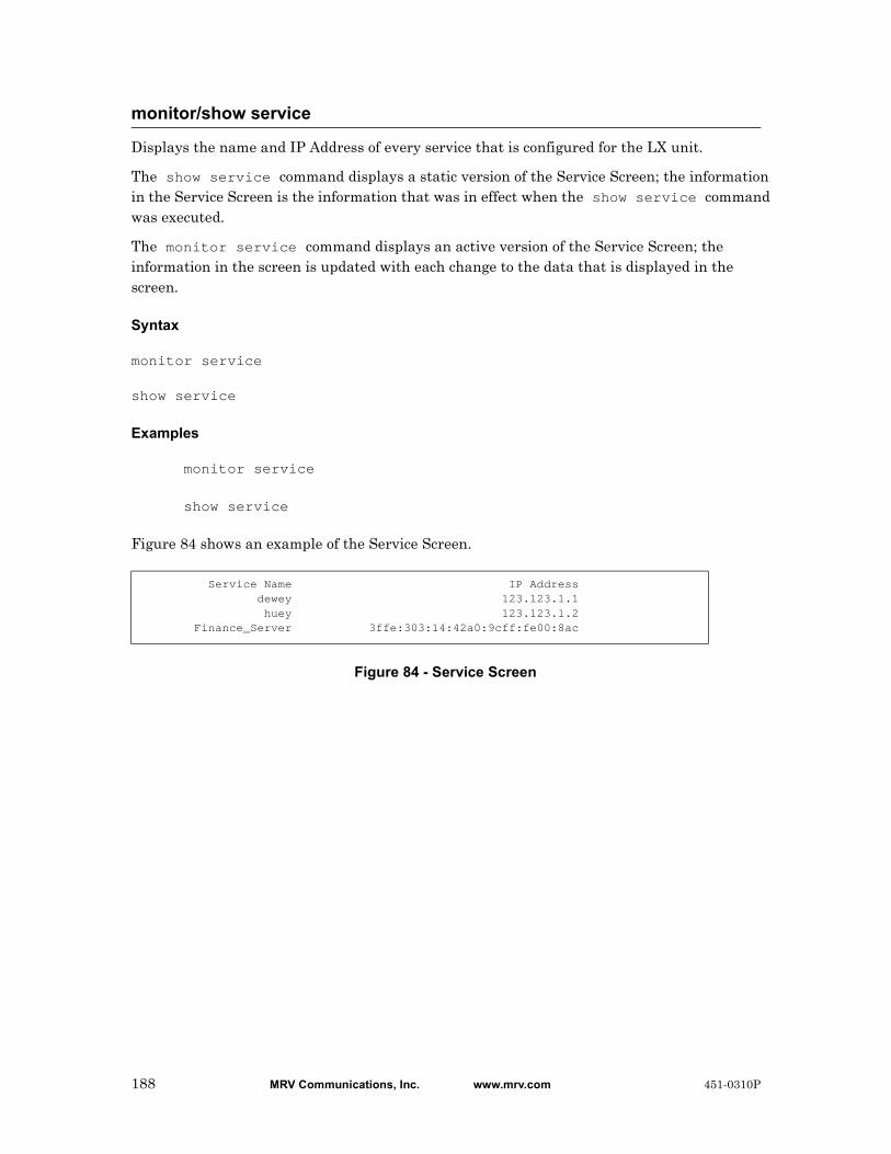
Displays the name and IP Address of every service that is configured for the LX unit.
The show service command displays a static version of the Service Screen; the information in the Service Screen is the information that was in effect when the show service command was executed.
The monitor service command displays an active version of the Service Screen; the information in the screen is updated with each change to the data that is displayed in the screen.
Syntax
monitor service
show service
Examples
monitor service
show service
Figure 84 shows an example of the Service Screen.
Figure 84 - Service Screen
monitor/show service
Service Name IP Address dewey 123.123.1.1 huey 123.123.1.2 Finance_Server 3ffe:303:14:42a0:9cff:fe00:8ac
188 MRV Communications, Inc. www.mrv.com 451-0310P

Displays information about opened sessions on the LX unit.
The show session command displays the static version of the Session Screen; the information in the screen is the information that was in effect when the show session command was executed.
The monitor session command displays an active version of the Session Screen; the information in the screen is updated with each change to the data that is displayed in the screen.
Syntax
monitor session [<session_number>]
show session [<session_number>]
Where Means
Usage Guidelines
If this command is executed without the <session_number> argument (i.e., show session), it displays information for all opened sessions on the LX unit.
Examples
monitor session 3
show session 3
Figure 85 shows an example of the Session screen.
Figure 85 - Session Screen
monitor/show session
session_number The session number of an opened connection.
Number Device Program Pid Time Status0 /dev/pts/0 Superuser 509 13302 *1 /dev/pts/0 User 510 13302 -2 /dev/pts/0 User 511 13302 -3 /dev/pts/0 User 512 13302 -
Field Description
Number The Session Number. The possible values are 1, 2, 3, or 4.
Device The Linux port name.
Program The program (or command mode) running on the LX unit.
451-0310P MRV Communications, Inc. www.mrv.com 189
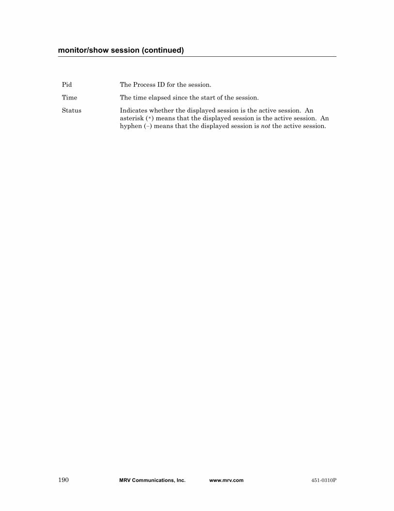
monitor/show session (continued)
Pid The Process ID for the session.
Time The time elapsed since the start of the session.
Status Indicates whether the displayed session is the active session. An asterisk (*) means that the displayed session is the active session. An hyphen (-) means that the displayed session is not the active session.
190 MRV Communications, Inc. www.mrv.com 451-0310P

Displays the system-level SNMP characteristics for the LX unit.
The show snmp characteristics command displays a static version of the SNMP Characteristics Screen; the information in the SNMP Characteristics Screen is the information that was in effect when the show snmp characteristics command was executed.
The monitor snmp characteristics command displays an active version of the SNMP Characteristics Screen; the information in the screen is updated with each change to the data that is displayed in the screen.
Syntax
monitor snmp characteristics
show snmp characteristics
Examples
monitor snmp characteristics
show snmp characteristics
Figure 87 shows an example of SNMP Characteristics Screen.
Figure 86 - SNMP Characteristics Screen
monitor/show snmp characteristics
Time: Wed, 10 Apr 2002 10:45:08 UTC Name: InReach Logging: Disabled Port: 161 Contact: Henry Smith Location: Upstairs Lab V3 Engine Boots: 14 V3 Engine ID: 6537303330336565616365323932336100000000
Field Description
Time The date and time that the show snmp characteristics command was executed.
Logging Indicates whether the SNMP Logging feature is Enabled or Disabled on the LX unit.
Contact The contact for the LX unit.
V3 Engine Boots The number of times the V3 engine has been rebooted.
V3 Engine ID The V3 Engine ID for the LX unit.
Name The system name for the LX unit.
Port The SNMP UDP port for the LX unit.
Location The location of the LX unit.
451-0310P MRV Communications, Inc. www.mrv.com 191

Displays information on SNMP clients.
The show snmp client command displays a static version of the SNMP Client Screen; the information in the SNMP Client Screen is the information that was in effect when the show snmp client command was executed.
The monitor snmp client command displays an active version of the SNMP Client Screen; the information in the screen is updated with each change to the data that is displayed in the screen.
Syntax
monitor snmp client all|<client_number>
show snmp client all|<client_number>
Where Means
Examples
monitor snmp client 1
show snmp client 1
Figure 87 shows an example of SNMP Client Screen.
Figure 87 - SNMP Client Screen
monitor/show snmp client
all Display information for all SNMP clients on this LX unit.
client_number The client number for an SNMP client
Get Client: 1 Address: 140.111.222.111 Version: v1 NetMask: 255.255.255.255 Community: public
Set Client: 1 Address: 140.111.222.111 Version: v1 NetMask: 255.255.255.255 Community: private
Trap Client: 1 Address: 140.111.222.111 Version: v1 UDP Port: 162 Community: public Retransmit Count: 0 Retransmit Interval: 0 V3 User Index: 0
Field Description
Get Client The SNMP client (e.g., a Network Operations Center, or NOC) which is permitted to perform an SNMP get on the LX unit.
192 MRV Communications, Inc. www.mrv.com 451-0310P
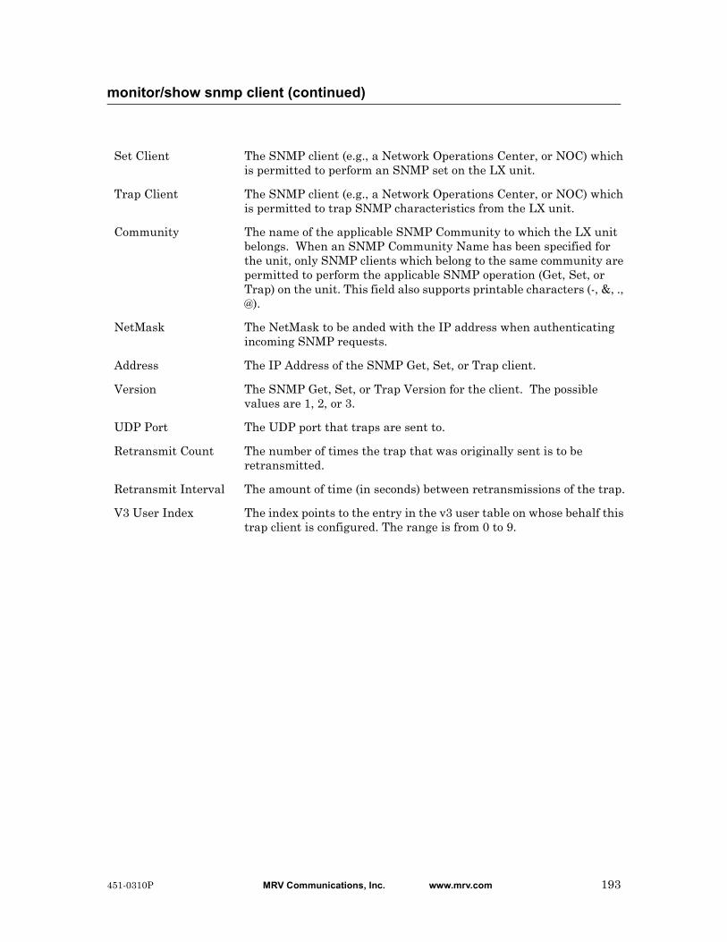
monitor/show snmp client (continued)
Set Client The SNMP client (e.g., a Network Operations Center, or NOC) which is permitted to perform an SNMP set on the LX unit.
Trap Client The SNMP client (e.g., a Network Operations Center, or NOC) which is permitted to trap SNMP characteristics from the LX unit.
Community The name of the applicable SNMP Community to which the LX unit belongs. When an SNMP Community Name has been specified for the unit, only SNMP clients which belong to the same community are permitted to perform the applicable SNMP operation (Get, Set, or Trap) on the unit. This field also supports printable characters (-, &, ., @).
NetMask The NetMask to be anded with the IP address when authenticating incoming SNMP requests.
Address The IP Address of the SNMP Get, Set, or Trap client.
Version The SNMP Get, Set, or Trap Version for the client. The possible values are 1, 2, or 3.
UDP Port The UDP port that traps are sent to.
Retransmit Count The number of times the trap that was originally sent is to be retransmitted.
Retransmit Interval The amount of time (in seconds) between retransmissions of the trap.
V3 User Index The index points to the entry in the v3 user table on whose behalf this trap client is configured. The range is from 0 to 9.
451-0310P MRV Communications, Inc. www.mrv.com 193

Displays V3 access information for SNMP clients.
The show snmp v3 access command displays a static version of the V3 Screen; the information in the V3 Screen is the information that was in effect when the show snmp v3 access command was executed.
The monitor show snmp v3 access command displays an active version of the V3 Screen; the information in the screen is updated with each change to the data that is displayed in the screen.
Syntax
monitor snmp v3 access all|<entry_number>
show snmp v3 access all|<entry_number>
Where Means
Examples
monitor snmp v3 access 3
monitor snmp v3 access all
show snmp v3 access 3
show snmp v3 access all
Figure 88 shows an example of the V3 Access Entry display.
Figure 88 - V3 Access Screen
monitor/show snmp v3 access
all Display all entries configured in the Access Table.
entry_number The Access Entry number.
accessEntry: 1 status: active groupName: tim readView: writeView: secModel: usm secLevel: noAuthNoPriv ctxPrefix: ctxMatch: exact
Field Description
Access Entry The number of the Access Entry
Group Name The name assigned to this entry.
194 MRV Communications, Inc. www.mrv.com 451-0310P

monitor/show snmp v3 access (continued)
Read View The name of the entry in the view table when processing Set requests.
Write View The name of the entry in the view table when processing Set requests.
Security Model The Security Model used by this entry.
CTX Prefix The value of the Context Prefix.
Status Status of the entry.
Security Level The Security Level used by this entry.
CTX Match The type of match to use against the Context Prefix.
451-0310P MRV Communications, Inc. www.mrv.com 195

Displays V3 group information for SNMP clients.
The show snmp v3 group command displays a static version of the V3 Screen; the information in the V3 Screen is the information that was in effect when the show snmp v3 group command was executed.
The monitor show snmp v3 group command displays an active version of the V3 Screen; the information in the screen is updated with each change to the data that is displayed in the screen.
Syntax
monitor snmp v3 group all|<entry_number>
show snmp v3 group all|<entry_number>
Where Means
Examples
monitor snmp v3 group 3
monitor snmp v3 group all
show snmp v3 group 3
show snmp v3 group all
Figure 89 shows an example of the V3 group display for an SNMP client.
Figure 89 - V3 Group Screen
monitor/show snmp v3 group
all Display all entries configured in the Access Table.
entry_number The client number for an SNMP client.
Entry: 1 status: active userName: sec groupName: tim secModel: usm
Field Description
Entry The number of the Entry.
userName The Name assigned to this entry.
groupName The name of the Access Table entry to which this user belongs.
secModel The security model used by this entry.
status The entry status.
196 MRV Communications, Inc. www.mrv.com 451-0310P

Displays miscellaneous V3 information for SNMP clients.
The show snmp v3 misc command displays a static version of the V3 Screen; the information in the V3 Screen is the information that was in effect when the show snmp v3 misc command was executed.
The monitor show snmp v3 misc command displays an active version of the V3 Screen; the information in the screen is updated with each change to the data that is displayed in the screen.
Syntax
monitor snmp v3 misc all|<entry_number>
show snmp v3 misc all|<entry_number>
Where Means
Examples
monitor snmp v3 misc 3
monitor snmp v3 misc all
show snmp v3 misc 3
show snmp v3 misc all
Figure 90 shows an example of the miscellaneous V3 display for an SNMP client.
Figure 90 - V3 Miscellaneous Screen
monitor/show snmp v3 misc
all Display miscellaneous information for all SNMP clients on this LX unit.
entry_number The client number for an SNMP client
EngineId: 800000210100000000 EngineBoots: 1
Field Description
Engine ID The SNMP V3 authoritative Engine ID.
Engine Boots The SNMP V3 Engine Boots value.
451-0310P MRV Communications, Inc. www.mrv.com 197

Displays V3 user information for SNMP clients.
The show snmp v3 user command displays a static version of the V3 Screen; the information in the V3 Screen is the information that was in effect when the show snmp v3 user command was executed.
The monitor show snmp v3 user command displays an active version of the V3 Screen; the information in the screen is updated with each change to the data that is displayed in the screen.
Syntax
monitor snmp v3 user all|<entry_number>
show snmp v3 user all|<entry_number>
Where Means
Examples
monitor snmp v3 user 3
monitor snmp v3 user all
show snmp v3 user 3
show snmp v3 user all
Figure 91 shows an example of the V3 user display for an SNMP client.
Figure 91 - V3 User Screen
monitor/show snmp v3 user
all Display user information for all SNMP clients on this LX unit.
entry_number The client number for an SNMP client
userEntry: 1 status: active userName: tim authPassword: privPassword: authProtocol: none privProtocol: none privPassword (Key): configured
Field Description
User Entry The Index in the User table.
User Name The name assigned to this user.
198 MRV Communications, Inc. www.mrv.com 451-0310P
monitor/show snmp v3 users (continued)
Authentication Password
The Authentication Password used by this user.
Privacy Password The Privacy Password used by this user.
Authentication Protocol
The Authentication Protocol used by this user.
Status The status of this user (Active or Inactive).
Privacy Protocol The Privacy Protocol used by this user.
Privacy Password (Key)
Indicates whether the Privacy key is configured or not.
451-0310P MRV Communications, Inc. www.mrv.com 199

Displays V3 view information for SNMP clients.
The show snmp v3 view command displays a static version of the V3 Screen; the information in the V3 Screen is the information that was in effect when the show snmp v3 view command was executed.
The monitor show snmp v3 view command displays an active version of the V3 Screen; the information in the screen is updated with each change to the data that is displayed in the screen.
Syntax
monitor snmp v3 view all|<entry_number>
show snmp v3 view all|<entry_number>
Where Means
Examples
monitor snmp v3 view 3
monitor snmp v3 view all
show snmp v3 view 3
show snmp v3 view all
Figure 92 shows an example of the V3 view display for an SNMP client.
Figure 92 - V3 View Screen
monitor/show snmp v3 view
all Display view information for all SNMP entries on this LX unit.
entry_number The entry number for an SNMP client
viewEntry: 1 status: active viewName: tim subTree: .1.3.6.1 mask: type: included
Field Description
View Entry The index assigned to this view entry in the View Table.
View Name The name assigned to the view entry.
Sub Tree The Object ID for this view entry.
200 MRV Communications, Inc. www.mrv.com 451-0310P

monitor/show snmp v3 view (continued)
View Mask A hexadecimal bit mask value to be used when checking incoming requests against the view.
View Type This indicates whether the matched OID is included or excluded from this view.
Status The status of this entry (Active or Inactive).
451-0310P MRV Communications, Inc. www.mrv.com 201

Displays the status or characteristics for selected subscribers.
The show subscriber command displays a static version of the Subscriber Characteristics Screen, the Subscriber Status Screen, or the Subscriber TCP Screen; the information in the displayed screen is the information that was in effect when the show subscriber command was executed.
The monitor subscriber command displays an active version of the Subscriber Characteristics Screen, the Subscriber Status Screen, or the Subscriber TCP Screen; the information in the screen is updated with each change to the data that is displayed in the screen.
Syntax
monitor subscriber <subscriber_name>|all characteristics|status|tcp
show subscriber <subscriber_name>|all characteristics|status|tcp
Where Means
Examples
monitor subscriber tim characteristics
show subscriber tim characteristics
monitor subscriber tim status
show subscriber tim status
monitor/show subscriber
subscriber_name The subscriber for which data is to be displayed.
all Display the specified data for all subscribers on the LX unit.
characteristics Displays the characteristics for the specified subscribers.
This option displays a screen that contains the same fields as the Subscriber Characteristics Screen that is displayed in the User Command Mode. For more information, refer to Figure 93 on page 203.
status Displays the status information for the specified subscribers.
This option displays a screen that contains the same fields as the Subscriber Status Screen that is displayed in the User Command Mode. For more information, refer to Figure 94 on page 205.
tcp Displays the TCP information for the selected subscribers.
This option displays a screen that contains the same fields as the Subscriber TCP Screen that is displayed in User Mode. For more information, refer to Figure 95 on page 206.
202 MRV Communications, Inc. www.mrv.com 451-0310P
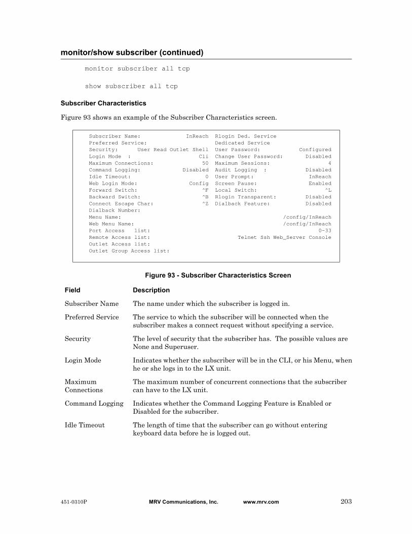
monitor subscriber all tcp
show subscriber all tcp
Subscriber Characteristics
Figure 93 shows an example of the Subscriber Characteristics screen.
Figure 93 - Subscriber Characteristics Screen
monitor/show subscriber (continued)
Subscriber Name: InReach Rlogin Ded. ServicePreferred Service: Dedicated ServiceSecurity: User Read Outlet Shell User Password: ConfiguredLogin Mode : Cli Change User Password: DisabledMaximum Connections: 50 Maximum Sessions: 4Command Logging: Disabled Audit Logging : DisabledIdle Timeout: 0 User Prompt: InReachWeb Login Mode: Config Screen Pause: EnabledForward Switch: ^F Local Switch: ^LBackward Switch: ^B Rlogin Transparent: DisabledConnect Escape Char: ^Z Dialback Feature: DisabledDialback Number:Menu Name: /config/InReachWeb Menu Name: /config/InReachPort Access list: 0-33Remote Access list: Telnet Ssh Web_Server ConsoleOutlet Access list:Outlet Group Access list:
Field Description
Subscriber Name The name under which the subscriber is logged in.
Preferred Service The service to which the subscriber will be connected when the subscriber makes a connect request without specifying a service.
Security The level of security that the subscriber has. The possible values are None and Superuser.
Login Mode Indicates whether the subscriber will be in the CLI, or his Menu, when he or she logs in to the LX unit.
Maximum Connections
The maximum number of concurrent connections that the subscriber can have to the LX unit.
Command Logging Indicates whether the Command Logging Feature is Enabled or Disabled for the subscriber.
Idle Timeout The length of time that the subscriber can go without entering keyboard data before he is logged out.
451-0310P MRV Communications, Inc. www.mrv.com 203

monitor/show subscriber (continued)
Web Login Mode The login mode that a subscriber can access. The options are Configuration and Menu.
Forward Switch The keyboard character that the subscriber types to switch to the next session.
Backward Switch The keyboard character that the subscriber types to switch to the previous session.
Dialback Feature Indicates whether or not the subscriber requires a dialback script in order to be logged in. (The dialback script contains commands that cause a modem to dial a designated telephone number.) The allowable values are Enabled and Disabled.
Connect Escape Char
The configured escape character for the local subscriber database. The default is ^Z.
Dialback Number The telephone number that the LX modem will dial when the subscriber makes a Dialback call to the LX unit.
Menu Name The name of the Menu assigned to the subscriber account.
Web Menu Name The name of the Web Menu assigned to the subscriber account. This name can be up to 22 characters long.
Port Access List The LX ports that the user can access.
Remote Access List The methods that the user can use to make remote connections.
Outlet Access List The individual outlets that the subscriber is authorized to manage.
Outlet Group Access List
The outlet groups that the subscriber is authorized to manage.
Rlogin Ded. Service
The rlogin service to which the subscriber is permanently assigned.
Dedicated Service The service to which the subscriber is permanently assigned.
User Password Indicates whether or not the subscriber must enter a password when he logs in to the account. If the value of this field is Disabled, the subscriber configured no password or configured a password without configuring password enable first. If the value of this field is Configured, the subscriber configured a password after configuring password enable. If the value of this field is Not Configured, the subscriber configured password enable after configuring the password while it was disabled (or never configured a password), and the subscriber has to configure the password again.
Change User Password
Indicates whether the Change User Password feature is Enabled or Disabled.
204 MRV Communications, Inc. www.mrv.com 451-0310P

Subscriber Status
Figure 94 shows an example of the Subscriber Status screen.
Figure 94 - Subscriber Status Screen
monitor/show subscriber (continued)
Maximum Sessions
The maximum number of concurrent sessions allowed for the subscriber.
Audit Logging Indicates whether the Audit Logging Feature is Enabled or Disabled.
User Prompt The subscriber-specific field of the subscriber User prompt. For example, for a subscriber prompt of InReach:0 >, the subscriber-specific field is InReach.
Screen Pause Indicates whether or not the screen is enabled to pause after 26 lines of output are displayed.
Local Switch The keyboard character that the subscriber types to return to the local command mode.
RLogin Transparent
Indicates whether rlogin is Enabled or Disabled.
Time: Mon, 23 May 2004 15:20:02 US/EasternSubs.name: miller Number of Connections: 2Configured TermType: Ansi Remote IP Address Local Port Protocol Devicemiller 0.0.0.0 41 Serial /dev/ttyGN41 Session 0 User Session 0 telnet 10.242.130.145 Session 0 Superuser Session 0 telnet 10.242.130.150miller 10.242.130.106 5040 Web Server Tcp/23840 Session 0 Superuser
Field Description
Subs. Name The name under which the subscriber is logged in.
Configured TermType
The terminal type that is configured for the subscriber.
Number of Connections
The number of connections that the subscriber currently has to the LX unit.
Remote IP Address If the user is logged in from a remote IP Address, the address is displayed in this field.
Local Port If the user is logged on to a local port of the LX unit, the port number is displayed in this field.
451-0310P MRV Communications, Inc. www.mrv.com 205
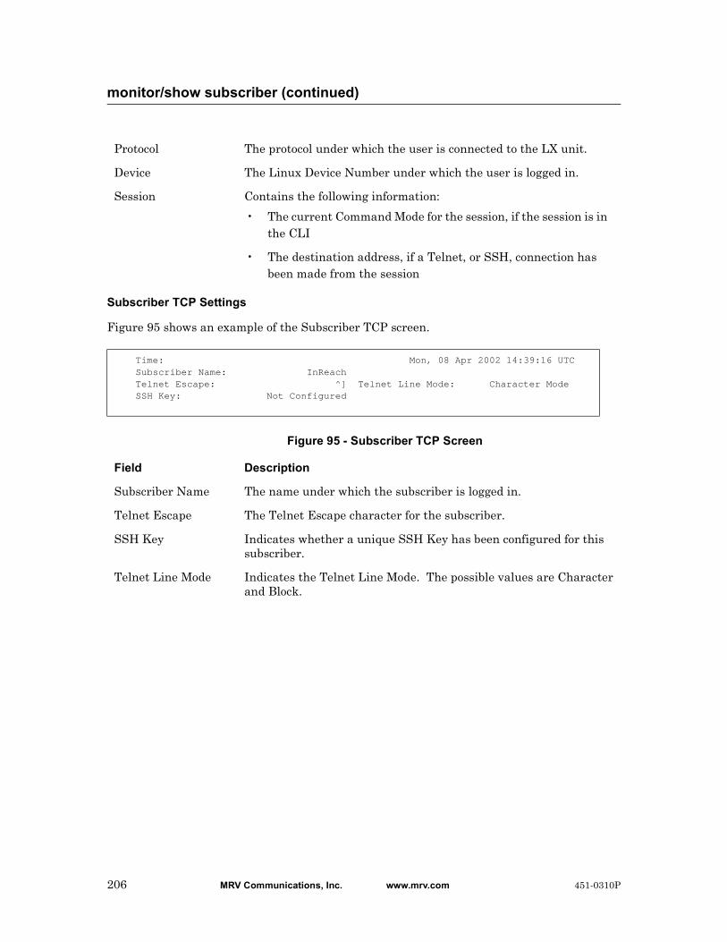
Subscriber TCP Settings
Figure 95 shows an example of the Subscriber TCP screen.
Figure 95 - Subscriber TCP Screen
monitor/show subscriber (continued)
Protocol The protocol under which the user is connected to the LX unit.
Device The Linux Device Number under which the user is logged in.
Session Contains the following information:
• The current Command Mode for the session, if the session is in the CLI
• The destination address, if a Telnet, or SSH, connection has been made from the session
Time: Mon, 08 Apr 2002 14:39:16 UTCSubscriber Name: InReachTelnet Escape: ^] Telnet Line Mode: Character ModeSSH Key: Not Configured
Field Description
Subscriber Name The name under which the subscriber is logged in.
Telnet Escape The Telnet Escape character for the subscriber.
SSH Key Indicates whether a unique SSH Key has been configured for this subscriber.
Telnet Line Mode Indicates the Telnet Line Mode. The possible values are Character and Block.
206 MRV Communications, Inc. www.mrv.com 451-0310P
Displays the Subscriber Characteristics Screen for your subscriber account.
NOTE: This command only displays the Subscriber Characteristics Screen for your subscriber account. Refer to the monitor/show subscribers command on page 202 to display the Subscriber Characteristics Screen for other subscribers’ accounts.
The show subscriber characteristics command displays a static version of your Subscriber Characteristics Screen; the information in the Subscriber Characteristics Screen is the information that was in effect when the show subscriber characteristics command was executed.
The monitor subscriber characteristics command displays an active version of the Subscriber Characteristics Screen; the information in the screen is updated with each change to the data that is displayed in the screen.
Syntax
monitor subscriber characteristics
show subscriber characteristics
Examples
monitor subscriber characteristics
show subscriber characteristics
Figure 93 on page 203 shows an example of the Subscriber Characteristics Screen.
monitor/show subscriber characteristics
451-0310P MRV Communications, Inc. www.mrv.com 207

Displays the Subscriber Status Screen for your subscriber account.
NOTE: This command only displays the Subscriber Status Screen for your subscriber account. Refer to the monitor/show subscribers command on page 202 to display the Subscriber Status Screen for other subscribers’ accounts.
The show subscriber status command displays a static version of your Subscriber Status Screen; the information in the Subscriber Status Screen is the information that was in effect when the show subscriber status command was executed.
The monitor subscriber status command displays an active version of the Subscriber Status Screen; the information in the screen is updated with each change to the data that is displayed in the screen.
Syntax
monitor subscriber status
show subscriber status
Examples
monitor subscriber status
show subscriber status
Figure 94 on page 205 shows an example of the Subscriber Status Screen.
monitor/show subscriber status
208 MRV Communications, Inc. www.mrv.com 451-0310P

Displays summary information for all of the subscribers configured on the LX unit.
The show subscriber summary command displays a static version of the Subscriber Summary Screen; the information in the Subscriber Summary Screen is the information that was in effect when the show subscriber summary command was executed.
The monitor subscriber summary command displays an active version of the Subscriber Summary Screen; the information in the screen is updated with each change to the data that is displayed in the screen.
Syntax
monitor subscriber summary
show subscriber summary
Examples
monitor subscriber summary
show subscriber summary
Figure 96 shows an example of the Subscriber Summary Screen.
Figure 96 - Subscriber Summary Screen
monitor/show subscriber summary
Name Connections Terminal Type InReach 0 Ansi demo 1 Ansi jack 0 Ansi
451-0310P MRV Communications, Inc. www.mrv.com 209

Displays the TCP Screen for your subscriber account.
NOTE: This command only displays the TCP Screen for your subscriber account. Refer to the monitor/show subscribers command on page 202 to display the TCP Screen for other subscribers’ accounts.
The show subscriber tcp command displays a static version of your Subscriber TCP Screen; the information in the Subscriber TCP Screen is the information that was in effect when the show subscriber tcp command was executed.
The monitor subscriber tcp command displays an active version of the Subscriber TCP Screen; the information in the screen is updated with each change to the data that is displayed in the screen.
Syntax
monitor subscriber tcp
show subscriber tcp
Examples
monitor subscriber tcp
show subscriber tcp
Figure 95 on page 206 shows an example of the Subscriber TCP Screen.
monitor/show subscriber tcp
210 MRV Communications, Inc. www.mrv.com 451-0310P

Displays the global system configuration for the LX unit.
The show system characteristics command displays a static version of the System Characteristics Screen; the information in the System Characteristics Screen is the information that was in effect when the show system characteristics command was executed.
The monitor system characteristics command displays an active version of the System Characteristics Screen; the information in the screen is updated with each change to the data that is displayed in the screen.
Syntax
monitor system characteristics
show system characteristics
Examples
monitor system characteristics
show system characteristics
Figure 97 shows an example of the System Characteristics Screen for an LX unit.
Figure 97 - System Characteristics Screen
monitor/show system characteristics
Name: In-Reach Time: Sat, 01 Jan 2005 06:01:49 UTC Serial Number: 00:a0:9c:00:02:b1 Authenticate Image: Enabled Location: Domain Name suffix: Maximum Number of Async Ports: 42 Internal Modem on Port: 41 Maximum Number of Subscribers: 100 LX Model Type: LX-8040-101 Maximum Number of Interfaces: 86 Maximum Number of Ethernet Ports: 1 Primary Domain : 0.0.0.0 Secondary Domain : 0.0.0.0 Gateway : 0.0.0.0 Default TFTP Server : 120.179.169.188 Timed Daemon: Disabled TFTP Retries: 3 NTP Daemon: Disabled TFTP Timeout: 3 NTP Server: 0.0.0.0 NTP Server Alternate: 0.0.0.0 NTP IPv6 Server: 3ffe:303:11:2222:220:edff:fe4b:fc67 NTP IPv6 Server Alternate: 3ffe:303:11:2222:220:edff:fe4b:fc68 Finger Daemon: Disabled Logging Size : 64000 Telnet Server: Disabled Telnet Client: Disabled Web Server: Enabled Web Server Port: 80 Web Server Timeout: 20 Web JceModule: JsafeJCE Web Encrypt: Enabled Web Banner: Enabled Subscriber Debug Option: Disabled Trigger-Action Debug Option: Disabled System Debug Option: Disabled Flash Debug Option: Disabled Minimum Password Length: 6 SSH Daemon: V2 Rlogin Client: Disabled Message Feature: Disabled SNMP Feature: Disabled Modem Pool Enabled Serial Ports:
Field Description
Name The host name of the LX unit.
451-0310P MRV Communications, Inc. www.mrv.com 211

monitor/show system characteristics (continued)
Serial Number The Serial Number of the LX unit.
Authenticate Image Indicates whether the Authenticate Image is Enabled or Disabled on the LX unit.
Location A text string that specifies the physical location of the LX unit.
Domain Name Suffix The suffix for the LX-unit Domain Name.
Maximum Number of Async Ports
The maximum allowable number of asynchronous ports on the LX unit.
Maximum Number of Subscribers
The maximum number of subscribers on the LX unit.
Maximum Number of Interfaces
The maximum allowable number of IP interfaces on the LX unit.
Primary Domain The IP Address of the Primary Domain Name Server (DNS) for the LX unit.
Gateway The IP Address for the gateway (default route) of the LX unit.
Timed Daemon Indicates whether the Timed Daemon is Enabled or Disabled.
NTP Daemon Indicates whether the Network Time Protocol (NTP) Daemon is Enabled or Disabled on the LX unit.
NTP Server The IP Address of the NTP server for the LX unit.
NTP IPv6 Server The NTP IPv6 Address of the NTP server for the LX unit.
NTP IPv6 Server Alternate
The alternate NTP IPv6 Address of the NTP server for the LX unit.
Finger Daemon Indicates whether the Finger Daemon (fingerd) is Enabled or Disabled on the LX unit.
Telnet Server Indicates whether the Telnet Server is Enabled or Disabled on the LX unit.
Web Server Indicates whether the WebServer feature (Browser Management) is Enabled or Disabled on the LX unit.
Web Server Timeout The length of time (in minutes) the GUI can remain onscreen before timing out. The range is from 1 to 240. The default is 20.
Web Encrypt Indicates whether the Web Encrypt feature is Enabled or Disabled on the LX unit.
Outlet Access Indicates whether Outlet Management is Enabled or Disabled on the LX unit.
212 MRV Communications, Inc. www.mrv.com 451-0310P

monitor/show system characteristics (continued)
Trigger-Action Debug Option
Indicates whether Trigger-Action Debug is Enabled or Disabled on the LX unit.
Subscriber Debug Option
Indicates whether Subscriber Debug is Enabled or Disabled on the LX unit.
LX Model Type Indicates the LX Model type. Note that in the -001 suffix, the first 0 indicates there is no internal modem for this unit. A 1 in this field indicates there is an external modem on this unit. The second 0 has no significance, and the third 1 is always a 1
SNMP Feature Indicates whether SNMP is Enabled or Disabled for the LX unit.
Modem Pool Enabled Serial Ports
The asynchronous ports that are included in the Modem Pool for the LX unit.
Time The date and time that the show system characteristics command was executed.
Internal Modem on Port
Indicates whether or not the LX port has an internal modem.
Maximum Number of Virtual Ports
The maximum allowable number of virtual ports on the LX unit.
Maximum Number of Ethernet Ports
The maximum allowable number of Ethernet ports on the LX unit.
Secondary Domain The IP Address of the Secondary Domain Name Server (DNS) for the LX unit.
Default TFTP Server The default network server for updating the software image, the iBoot file, and parameter files.
TFTP Retries The number of times the TFTP server will attempt to communicate with the LX unit.
TFTP Timeout If the LX unit can not load from the TFTP Server before the expiration of this timeout, the TFTP Server is considered dead.
NTP Server Alternate
An alternate NTP server for the LX unit.
Logging Size Indicates the size of logging files on the unit.
SSH Daemon Indicates whether the SSH Daemon is Enabled or Disabled on the LX unit. If SSH is Enabled, the SSH Version (V1 or V2) is displayed in this field. Otherwise, the word Disabled is displayed in this field.
Telnet Client Indicates whether the Telnet Client is Enabled or Disabled on the LX unit.
Web Server Port The LX port configured as a web server port. The range is 1 - 65535.
451-0310P MRV Communications, Inc. www.mrv.com 213
monitor/show system characteristics (continued)
Web JCE Module Indicates the name of the web server JCE Module. The name is set by the module vendor. The default is a null string.
Web Banner Indicates whether or not the Web Banner Feature is enabled.
Debug Option Indicates whether the System Debug option is Enabled or Disabled for this LX unit.
Minimum Password Length
Indicates the Minimum Password Length allowable.
RLogin Client Indicates whether the rlogin Client option is Enabled or Disabled for this LX unit.
Message Feature Indicates whether the Message Feature is Enabled or Disabled for this LX unit.
214 MRV Communications, Inc. www.mrv.com 451-0310P
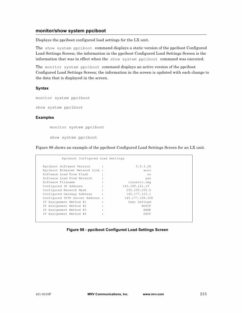
Displays the ppciboot configured load settings for the LX unit.
The show system ppciboot command displays a static version of the ppciboot Configured Load Settings Screen; the information in the ppciboot Configured Load Settings Screen is the information that was in effect when the show system ppciboot command was executed.
The monitor system ppciboot command displays an active version of the ppciboot Configured Load Settings Screen; the information in the screen is updated with each change to the data that is displayed in the screen.
Syntax
monitor system ppciboot
show system ppciboot
Examples
monitor system ppciboot
show system ppciboot
Figure 98 shows an example of the ppciboot Configured Load Settings Screen for an LX unit.
Figure 98 - ppciboot Configured Load Settings Screen
monitor/show system ppciboot
Ppciboot Configured Load Settings
Ppciboot Software Version : 0.9.3.26 Ppciboot Ethernet Network Link : auto Software Load From Flash : no Software Load From Network : yes Software Filename : linuxito.img Configured IP Address : 145.189.121.19 Configured Network Mask : 255.255.255.0 Configured Gateway Address : 145.177.123.1 Configured TFTP Server Address : 145.177.169.208 IP Assignment Method #1 : User Defined IP Assignment Method #2 : BOOTP IP Assignment Method #3 : RARP IP Assignment Method #4 : DHCP
451-0310P MRV Communications, Inc. www.mrv.com 215

Displays system power information for the LX unit.
The show system power command displays a static version of the System Power Screen; the information in the System Power Screen is the information that was in effect when the show system power command was executed.
The monitor system power command displays an active version of the System Power Screen; the information in the screen is updated with each change to the data that is displayed in the screen.
Syntax
monitor system power
show system power
Examples
monitor system power
show system power
Figure 100 shows an example of the System Power Screen for an LX unit.
Figure 99 - System Power Screen
monitor/show system power
LX Power Supply Status Mon, 04 Oct 2004 09:03:02 US/EASTERN Power Supply Type: N/A Power Supply A: N/A Power Supply B: N/A Power A Input: N/A Power B Input: N/A Power A Output: N/A Power B Output: N/APowerFail Log:01: Tue Sep 28 15:50:57 2004 - AC failure02: Thu Sep 30 08:20:49 2004 - AC failure03: Fri Oct 1 10:20:15 2004 - AC failure04: No entry05: No entry06: No entry07: No entry08: No entry
Field Description
Power Supply Type The type of power supply (AC or DC). Not applicable if not supported on your LX Model type.
Power Supply A The status of Power Supply A. Not applicable if not supported on your LX Model type.
216 MRV Communications, Inc. www.mrv.com 451-0310P

monitor/show system power (continued)
Power Supply A Input
The input of Power Supply A. Not applicable if not supported on your LX Model type.
Power Supply A Output
The output of Power Supply A. Not applicable if not supported on your LX Model type.
Power Supply B The status of Power Supply B. Not applicable if not supported on your LX Model type.
Power Supply B Input
The input of Power Supply B. Not applicable if not supported on your LX Model type.
Power Supply B Output
The output of Power Supply B. Not applicable if not supported on your LX Model type.
PowerFail Log The dates and times when power failures have occurred on the LX unit. Also includes an explanation of the failure.
Note: This field also displays the date and time when the LX unit is unplugged.
451-0310P MRV Communications, Inc. www.mrv.com 217
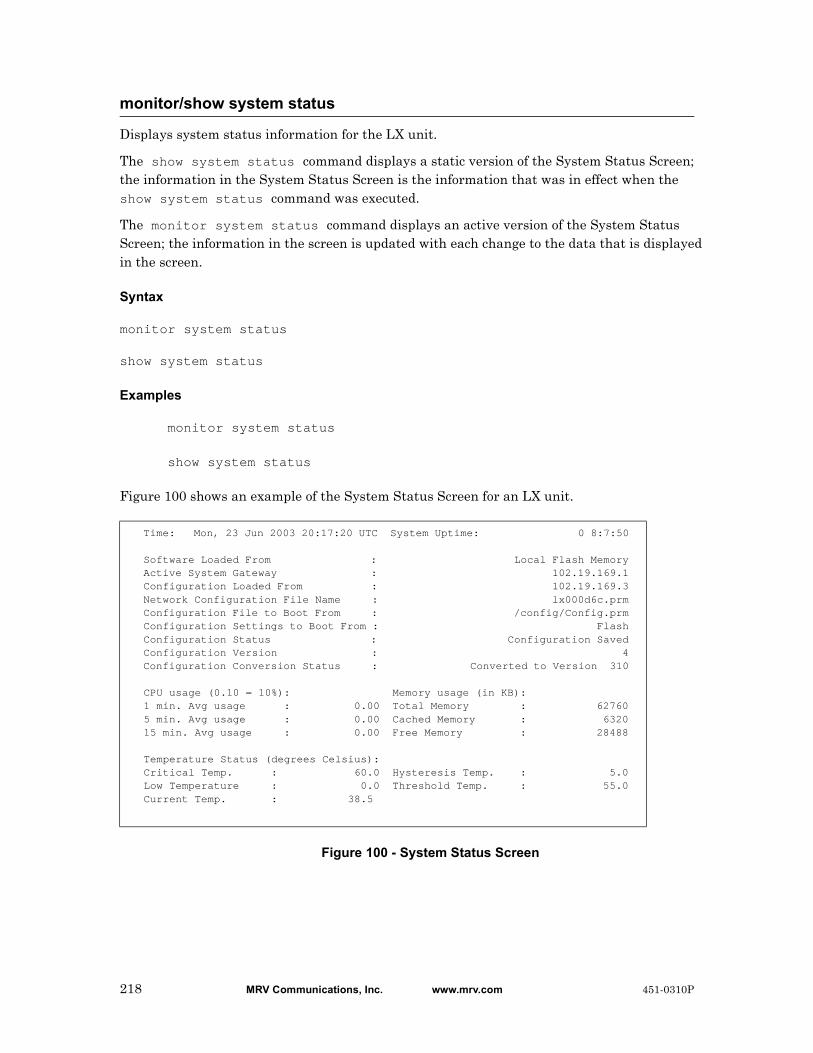
Displays system status information for the LX unit.
The show system status command displays a static version of the System Status Screen; the information in the System Status Screen is the information that was in effect when the show system status command was executed.
The monitor system status command displays an active version of the System Status Screen; the information in the screen is updated with each change to the data that is displayed in the screen.
Syntax
monitor system status
show system status
Examples
monitor system status
show system status
Figure 100 shows an example of the System Status Screen for an LX unit.
Figure 100 - System Status Screen
monitor/show system status
Time: Mon, 23 Jun 2003 20:17:20 UTC System Uptime: 0 8:7:50
Software Loaded From : Local Flash Memory Active System Gateway : 102.19.169.1 Configuration Loaded From : 102.19.169.3 Network Configuration File Name : lx000d6c.prm Configuration File to Boot From : /config/Config.prm Configuration Settings to Boot From : Flash Configuration Status : Configuration Saved Configuration Version : 4 Configuration Conversion Status : Converted to Version 310
CPU usage (0.10 = 10%): Memory usage (in KB): 1 min. Avg usage : 0.00 Total Memory : 62760 5 min. Avg usage : 0.00 Cached Memory : 6320 15 min. Avg usage : 0.00 Free Memory : 28488
Temperature Status (degrees Celsius): Critical Temp. : 60.0 Hysteresis Temp. : 5.0 Low Temperature : 0.0 Threshold Temp. : 55.0 Current Temp. : 38.5
218 MRV Communications, Inc. www.mrv.com 451-0310P

monitor/show system status (continued)
Field Description
Software Loaded From
The IP Address of the Load Server for the LX software image.
Active System Gateway
The IP Address of the gateway that is currently being used by the LX unit.
Configuration Loaded From
The parameter server for the LX unit.
Network Configuration File Name
The filename of the network file from which the LX configuration is loaded.
Configuration File to Boot From
The filename of the file from which the LX unit is booted.
Configuration Settings to Boot From
Indicates whether the configuration of the LX unit is booted from the local flash or from the network.
Configuration Status Indicates whether the current configuration of the LX unit has been saved or has been compromised. If the configuration file is loaded from the network host, and that file has been edited on the network host, the configuration file is considered to be compromised. The status will remain compromised until a different configuration file is loaded.
Configuration Version
The version number of the LX configuration. This number is incremented by 1 each time a modified version of the LX configuration is saved.
Configuration Conversion Status
The LX version to which the existing configuration was converted.
CPU usage (0.10 = 10%)
1 min. Avg usage Average CPU usage over the last minute.
5 min. Avg usage Average CPU usage over the last 5 minutes.
15 min. Avg usage Average CPU usage over the last 15 minutes.
Memory usage (in KB)
Total Memory The total memory on the LX unit (in KB).
Cached Memory The total cached memory in use (in KB).
Free Memory The total free memory (in KB).
451-0310P MRV Communications, Inc. www.mrv.com 219
monitor/show system status (continued)
Temperature Status (degrees Celsius)
Critical Temp. The temperature level (in Celsius degrees) that is considered critical for the LX unit.
Low Temperature The lowest supported operating temperature for the LX unit.
Current Temp. The current temperature of the LX unit.
Hysteresis Temp. The Hysteresis for temperature measurements on the LX unit.
Threshold Temp. The highest supported operating temperature for the LX unit.
PowerFail Log The dates and times when power failures have occurred on the LX unit.
Note: This field also displays the date and time when the LX unit is unplugged.
220 MRV Communications, Inc. www.mrv.com 451-0310P
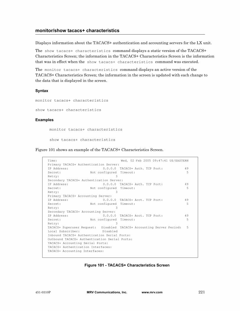
Displays information about the TACACS+ authentication and accounting servers for the LX unit.
The show tacacs+ characteristics command displays a static version of the TACACS+ Characteristics Screen; the information in the TACACS+ Characteristics Screen is the information that was in effect when the show tacacs+ characteristics command was executed.
The monitor tacacs+ characteristics command displays an active version of the TACACS+ Characteristics Screen; the information in the screen is updated with each change to the data that is displayed in the screen.
Syntax
monitor tacacs+ characteristics
show tacacs+ characteristics
Examples
monitor tacacs+ characteristics
show tacacs+ characteristics
Figure 101 shows an example of the TACACS+ Characteristics Screen.
Figure 101 - TACACS+ Characteristics Screen
monitor/show tacacs+ characteristics
Time: Wed, 02 Feb 2005 09:47:41 US/EASTERN Primary TACACS+ Authentication Server: IP Address: 0.0.0.0 TACACS+ Auth. TCP Port: 49 Secret: Not configured Timeout: 5 Retry: 3 Secondary TACACS+ Authentication Server: IP Address: 0.0.0.0 TACACS+ Auth. TCP Port: 49 Secret: Not configured Timeout: 5 Retry: 3 Primary TACACS+ Accounting Server: IP Address: 0.0.0.0 TACACS+ Acct. TCP Port: 49 Secret: Not configured Timeout: 5 Retry: 3 Secondary TACACS+ Accounting Server: IP Address: 0.0.0.0 TACACS+ Acct. TCP Port: 49 Secret: Not configured Timeout: 5 Retry: 3 TACACS+ Superuser Request: Disabled TACACS+ Accounting Server Period: 5 Local Subscriber: Disabled Inbound TACACS+ Authentication Serial Ports: Outbound TACACS+ Authentication Serial Ports: TACACS+ Accounting Serial Ports: TACACS+ Authentication Interfaces: TACACS+ Accounting Interfaces:
451-0310P MRV Communications, Inc. www.mrv.com 221
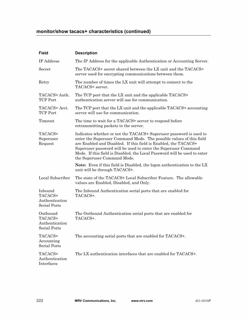
monitor/show tacacs+ characteristics (continued)
Field Description
IP Address The IP Address for the applicable Authentication or Accounting Server.
Secret The TACACS+ secret shared between the LX unit and the TACACS+ server used for encrypting communications between them.
Retry The number of times the LX unit will attempt to connect to the TACACS+ server.
TACACS+ Auth. TCP Port
The TCP port that the LX unit and the applicable TACACS+ authentication server will use for communication.
TACACS+ Acct. TCP Port
The TCP port that the LX unit and the applicable TACACS+ accounting server will use for communication.
Timeout The time to wait for a TACACS+ server to respond before retransmitting packets to the server.
TACACS+ Superuser Request
Indicates whether or not the TACACS+ Superuser password is used to enter the Superuser Command Mode. The possible values of this field are Enabled and Disabled. If this field is Enabled, the TACACS+ Superuser password will be used to enter the Superuser Command Mode. If this field is Disabled, the Local Password will be used to enter the Superuser Command Mode.
Note: Even if this field is Disabled, the logon authentication to the LX unit will be through TACACS+.
Local Subscriber The state of the TACACS+ Local Subscriber Feature. The allowable values are Enabled, Disabled, and Only.
Inbound TACACS+ Authentication Serial Ports
The Inbound Authentication serial ports that are enabled for TACACS+.
Outbound TACACS+ Authentication Serial Ports
The Outbound Authentication serial ports that are enabled for TACACS+.
TACACS+ Accounting Serial Ports
The accounting serial ports that are enabled for TACACS+.
TACACS+ Authentication Interfaces
The LX authentication interfaces that are enabled for TACACS+.
222 MRV Communications, Inc. www.mrv.com 451-0310P

monitor/show tacacs+ characteristics (continued)
TACACS+ Accounting Interfaces
The LX accounting interfaces that are enabled for TACACS+.
451-0310P MRV Communications, Inc. www.mrv.com 223
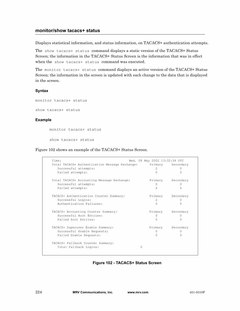
Displays statistical information, and status information, on TACACS+ authentication attempts.
The show tacacs+ status command displays a static version of the TACACS+ Status Screen; the information in the TACACS+ Status Screen is the information that was in effect when the show tacacs+ status command was executed.
The monitor tacacs+ status command displays an active version of the TACACS+ Status Screen; the information in the screen is updated with each change to the data that is displayed in the screen.
Syntax
monitor tacacs+ status
show tacacs+ status
Example
monitor tacacs+ status
show tacacs+ status
Figure 102 shows an example of the TACACS+ Status Screen.
Figure 102 - TACACS+ Status Screen
monitor/show tacacs+ status
Time: Wed, 08 May 2002 13:32:34 UTCTotal TACACS+ Authentication Message Exchange: Primary Secondary Successful attempts: 2 0 Failed attempts: 0 0
Total TACACS+ Accounting Message Exchange: Primary Secondary Successful attempts: 0 0 Failed attempts: 6 6
TACACS+ Authentication Counter Summary: Primary Secondary Successful Logins: 2 0 Authentication Failures: 0 0
TACACS+ Accounting Counter Summary: Primary Secondary Successful Acct Entries: 0 0 Failed Acct Entries: 0 0
TACACS+ Superuser Enable Summary: Primary Secondary Successful Enable Requests: 0 0 Failed Enable Requests: 0 0
TACACS+ Fallback Counter Summary: Total Fallback Logins: 0
224 MRV Communications, Inc. www.mrv.com 451-0310P

monitor/show tacacs+ status (continued)
Field Description
Total TACACS+ Authentication Message Exchange
Successful Attempts
The number of times the primary and secondary TACACS+ authentication servers successfully exchanged messages with the LX unit.
Failed attempts
The number of times the primary and secondary TACACS+ authentication servers failed to exchange messages with the LX unit.
Total TACACS+ Accounting Message Exchange
Successful Attempts
The number of times the primary and secondary TACACS+ accounting servers successfully exchanged messages with the LX unit.
Failed attempts
The number of times the primary and secondary TACACS+ accounting servers failed to exchange messages with the LX unit.
TACACS+ Authentication Counter Summary
Successful Logins
The number of successful logins using TACACS+.
Authentication Failures
The number of unsuccessful logins using TACACS+.
TACACS+ Accounting Counter Summary
Successful Acct Entries
The number of successful TACACS+ accounting entries.
Failed Acct Entries
The number of failed TACACS+ accounting entries.
TACACS+ Superuser Enable Summary
Successful Enable Requests
This field only contains a value if TACACS+ Superuser Request is enabled. If TACACS+ Superuser Request is enabled, this field indicates the number of successful logins to Superuser Mode.
Failed Enable Requests
This field only contains a value if TACACS+ Superuser Request is enabled. If TACACS+ Superuser Request is enabled, this field indicates the number of unsuccessful attempts at logging in to Superuser Mode.
TACACS+ Fallback Counter Summary
Total Fallback Logins
The number of logins that have been done through the TACACS+ Fallback Login feature.
451-0310P MRV Communications, Inc. www.mrv.com 225

Displays summary data for the TACACS+ authentication and accounting servers.
The show tacacs+ summary command displays a static version of the TACACS+ Summary Screen; the information in the TACACS+ Summary Screen is the information that was in effect when the show tacacs+ summary command was executed.
The monitor tacacs+ summary command displays an active version of the TACACS+ Summary Screen; the information in the screen is updated with each change to the data that is displayed in the screen.
Syntax
monitor tacacs+ summary
show tacacs+ summary
Examples
monitor tacacs+ summary
show tacacs+ summary
Figure 103 shows an example of the TACACS+ Summary Screen.
Figure 103 - TACACS+ Summary Screen
monitor/show tacacs+ summary
TACACS+ Server Summary Thu, 12 Sep 2002 20:47:18 Primary Auth. Server: 0.0.0.0 Primary Auth. TCP Port: 49 Secondary Auth. Server: 0.0.0.0 Secondary Auth. TCP Port: 49 Primary Acct. Server: 0.0.0.0 Primary Acct. TCP Port: 49 Secondary Acct. Server: 0.0.0.0 Secondary Acct. TCP Port: 49
Field Description
Primary Auth. Server
The IP Address of the Primary TACACS+ Authentication server.
Secondary Auth. Server
The IP Address of the Secondary TACACS+ Authentication server.
Primary Acct. Server
The IP Address of the Primary TACACS+ Accounting server.
Secondary Acct. Server
The IP Address of the Secondary TACACS+ Accounting server.
Primary Auth. TCP Port
The TCP port for the Primary TACACS+ Authentication server.
226 MRV Communications, Inc. www.mrv.com 451-0310P

monitor/show tacacs+ summary (continued)
Secondary Auth. TCP Port
The TCP port for the Secondary TACACS+ Authentication server.
Primary Acct. TCP Port
The TCP port for the Primary TACACS+ Accounting server.
Secondary Acct. TCP Port
The TCP port for the Secondary TACACS+ Accounting server.
451-0310P MRV Communications, Inc. www.mrv.com 227
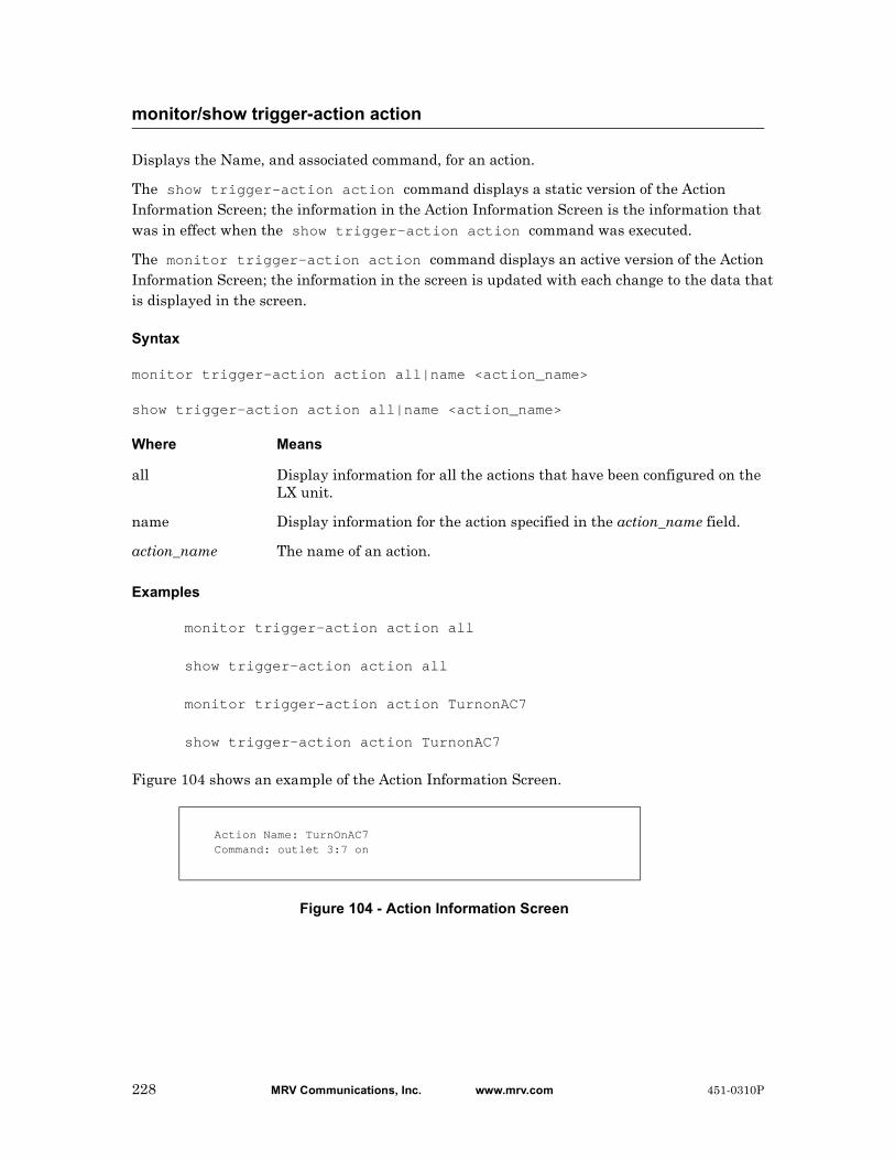
Displays the Name, and associated command, for an action.
The show trigger-action action command displays a static version of the Action Information Screen; the information in the Action Information Screen is the information that was in effect when the show trigger-action action command was executed.
The monitor trigger-action action command displays an active version of the Action Information Screen; the information in the screen is updated with each change to the data that is displayed in the screen.
Syntax
monitor trigger-action action all|name <action_name>
show trigger-action action all|name <action_name>
Where Means
Examples
monitor trigger-action action all
show trigger-action action all
monitor trigger-action action TurnonAC7
show trigger-action action TurnonAC7
Figure 104 shows an example of the Action Information Screen.
Figure 104 - Action Information Screen
monitor/show trigger-action action
all Display information for all the actions that have been configured on the LX unit.
name Display information for the action specified in the action_name field.
action_name The name of an action.
Action Name: TurnOnAC7Command: outlet 3:7 on
228 MRV Communications, Inc. www.mrv.com 451-0310P

Displays information on a rule.
The show trigger-action rule characteristics command displays a static version of the Rule Information Screen; the information in the Rule Information Screen is the information that was in effect when the show trigger-action rule characteristics command was executed.
The monitor trigger-action rule characteristics command displays an active version of the Rule Information Screen; the information in the screen is updated with each change to the data that is displayed in the screen.
Syntax
monitor trigger-action rule all|name <rule_name> characteristics
show trigger-action rule all|name <rule_name> characteristics
Where Means
Examples
monitor trigger-action rule all characteristics
show trigger-action rule all characteristics
monitor trigger-action rule ACTurnOnRule7 characteristics
show trigger-action rule ACTurnOnRule7 characteristics
Figure 105 shows an example of the Rule Information Screen.
Figure 105 - Rule Information Screen
monitor/show trigger-action rule characteristics
all Display information for all the rules that have been configured on the LX unit.
name Display information for the rule specified in the rule_name field.
rule_name The name of a rule.
Rule Name: ACTurnOnRule7State: disabledTrigger Name: TempGT30c Type: Temperature (F)Action Name: TurnOnAC7 Command: outlet 3:7 on
Field Description
Rule Name The Name of the Rule.
451-0310P MRV Communications, Inc. www.mrv.com 229

monitor/show trigger-action rule characteristics (continued)
State The current state (Enabled/Disabled) of the Rule.
Trigger Name The Trigger associated with the Rule.
Type The type of the Trigger (i.e., Humidity, Ping, Temperature, or Timer).
Action Name The Action associated with the Rule.
Command The LX command configured for the Action.
230 MRV Communications, Inc. www.mrv.com 451-0310P
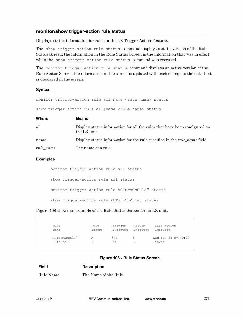
Displays status information for rules in the LX Trigger-Action Feature.
The show trigger-action rule status command displays a static version of the Rule Status Screen; the information in the Rule Status Screen is the information that was in effect when the show trigger-action rule status command was executed.
The monitor trigger-action rule status command displays an active version of the Rule Status Screen; the information in the screen is updated with each change to the data that is displayed in the screen.
Syntax
monitor trigger-action rule all|name <rule_name> status
show trigger-action rule all|name <rule_name> status
Where Means
Examples
monitor trigger-action rule all status
show trigger-action rule all status
monitor trigger-action rule ACTurnOnRule7 status
show trigger-action rule ACTurnOnRule7 status
Figure 106 shows an example of the Rule Status Screen for an LX unit.
Figure 106 - Rule Status Screen
monitor/show trigger-action rule status
all Display status information for all the rules that have been configured on the LX unit.
name Display status information for the rule specified in the rule_name field.
rule_name The name of a rule.
Rule Rule Trigger Action Last Action Name Errors Executed Executed Executed
ACTurnOnRule7 0 344 2 Wed Sep 24 09:40:00 TurnOnAC1 0 85 0 Never
Field Description
Rule Name The Name of the Rule.
451-0310P MRV Communications, Inc. www.mrv.com 231

monitor/show trigger-action rule status (continued)
Rule Errors The number of times the Rule has misfired (i.e., failed to fire despite the condition of the Trigger being true).
Trigger Executed The number of times the Rule has been fired due to the Trigger Condition Being true.
Action Executed The number of times the Action associated with the Rule has been executed.
Last Action Executed
The date and time that the Action associated with this Rule was last executed.
232 MRV Communications, Inc. www.mrv.com 451-0310P
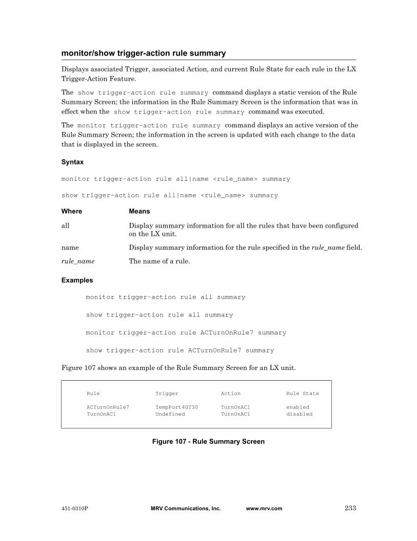
Displays associated Trigger, associated Action, and current Rule State for each rule in the LX Trigger-Action Feature.
The show trigger-action rule summary command displays a static version of the Rule Summary Screen; the information in the Rule Summary Screen is the information that was in effect when the show trigger-action rule summary command was executed.
The monitor trigger-action rule summary command displays an active version of the Rule Summary Screen; the information in the screen is updated with each change to the data that is displayed in the screen.
Syntax
monitor trigger-action rule all|name <rule_name> summary
show trigger-action rule all|name <rule_name> summary
Where Means
Examples
monitor trigger-action rule all summary
show trigger-action rule all summary
monitor trigger-action rule ACTurnOnRule7 summary
show trigger-action rule ACTurnOnRule7 summary
Figure 107 shows an example of the Rule Summary Screen for an LX unit.
Figure 107 - Rule Summary Screen
monitor/show trigger-action rule summary
all Display summary information for all the rules that have been configured on the LX unit.
name Display summary information for the rule specified in the rule_name field.
rule_name The name of a rule.
Rule Trigger Action Rule State
ACTurnOnRule7 TempPort4GT30 TurnOnAC1 enabled TurnOnAC1 Undefined TurnOnAC1 disabled
451-0310P MRV Communications, Inc. www.mrv.com 233

Displays information on a trigger.
The show trigger-action trigger command displays a static version of the Trigger Information Screen; the information in the Trigger Information Screen is the information that was in effect when the show trigger-action trigger command was executed.
The monitor trigger-action trigger command displays an active version of the Trigger Information Screen; the information in the screen is updated with each change to the data that is displayed in the screen.
Syntax
monitor trigger-action trigger all|name <trigger_name>
show trigger-action trigger all|name <trigger_name>
Where Means
Examples
monitor trigger-action trigger all
show trigger-action trigger all
monitor trigger-action trigger TempPort4GT30
show trigger-action trigger TempPort4GT30
The following figures show examples of Trigger Information Screens for each type of trigger.
Figure 108 shows an example of the Trigger Information Screen for a Humidity Trigger.
Figure 108 - Trigger Information Screen (Humidity Trigger)
monitor/show trigger-action trigger
all Display information for all the triggers that have been configured on the LX unit.
name Display information for the rule specified in the trigger_name field.
trigger_name The name of a trigger.
Trigger Name: HumPort2GT85 Type: HumidityPort: 2Hysteresis: +/- 5 percentHumidity > 90
234 MRV Communications, Inc. www.mrv.com 451-0310P

Figure 109 shows an example of the Trigger Information Screen for a Pattern Trigger.
Figure 109 - Trigger Information Screen (Pattern Trigger)Figure 110 shows an example of the Trigger Information Screen for a Ping Trigger.
Figure 110 - Trigger Information Screen (Ping Trigger)Figure 111 shows an example of the Trigger Information Screen for a Signal Trigger.
Figure 111 - Trigger Information Screen (Signal Trigger)Figure 112 shows an example of the Trigger Information Screen for a Temperature Trigger.
Figure 112 - Trigger Information Screen (Temperature Trigger)Figure 113 shows an example of the Trigger Information Screen for a Timer Trigger.
Figure 113 - Trigger Information Screen (Timer Trigger)
monitor/show trigger-action trigger (continued)
Trigger Name: Port3Trigger Type: Pattern Port: 3 Pattern String: .c*\.\*
Trigger Name: RockyIsReachable Type: Ping Status: Up Address: 154.54.67.78 Interval: 90 Interface: 1
Trigger Name: Port3CTShigh Type: Signal Port: 3 Signal: CTS Status: High
Trigger Name: TempGT30c Type: Temperature (F) Port: 3 Hysteresis: +/- 1 degree Temperature > 30
Trigger Name: SundayAt6AM Type: Timer Date: */* Time: 6:00 Day: sunTimer Tester:(1) Sun Aug 3 06:00:00 2003(2) Sun Aug 10 06:00:00 2003(3) Sun Aug 17 06:00:00 2003(4) Sun Aug 24 06:00:00 2003(5) Sun Aug 31 06:00:00 2003
451-0310P MRV Communications, Inc. www.mrv.com 235
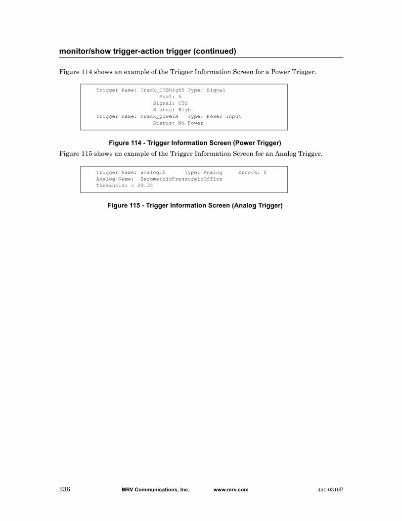
Figure 114 shows an example of the Trigger Information Screen for a Power Trigger.
Figure 114 - Trigger Information Screen (Power Trigger)Figure 115 shows an example of the Trigger Information Screen for an Analog Trigger.
Figure 115 - Trigger Information Screen (Analog Trigger)
monitor/show trigger-action trigger (continued)
Trigger Name: Track_CTShigh5 Type: Signal Port: 5 Signal: CTS Status: HighTrigger name: track_powerA Type: Power Input Status: No Power
Trigger Name: analog10 Type: Analog Errors: 0Analog Name: BarometricPressureinOfficeThreshold: > 29.35
236 MRV Communications, Inc. www.mrv.com 451-0310P

Displays information about each user that is currently logged in to the LX unit.
The show users command displays a static version of the Users Screen; the information in the Users Screen is the information that was in effect when the show users command was executed.
The monitor users command displays an active version of the Users Screen; the information in the screen is updated with each change to the data that is displayed in the screen.
Syntax
monitor users
show users
Example
show users
Figure 116 shows an example of the Users Screen.
Figure 116 - Users Screen
monitor/show users
Name Remote IP Address Local Port Protocol Devicedon 0.0.0.0 0 Serial /dev/ttyCPM0InReach 120.159.168.175 23 Telnet /dev/pts/0
Name Remote IP Address Local Port Protocol Devicedon 0.0.0.0 0 Serial /dev/ttyCPM0InReach 120.159.168.175 23 Telnet /dev/pts/010
Field Description
Name The user name
Remote IP Address If the user is logged in from a remote IP Address, the address is displayed in this field.
Local Port If the user is logged on to a local port of the LX unit, the port number is displayed in this field.
Protocol The protocol under which the user is connected to the LX unit.
Device The Linux Device Number under which the user is logged in.
451-0310P MRV Communications, Inc. www.mrv.com 237

Displays the Linux OS version, Linux In-Reach version, LX software version, and ppciboot version for the LX unit.
The show version command displays a static version of the Version Screen; the information in the Version Screen is the information that was in effect when the show version command was executed.
The monitor version command displays an active version of the Version Screen; the information in the screen is updated with each change to the data that is displayed in the screen.
Syntax
monitor version
show version
Examples
monitor version
show version
Figure 117 shows an example of the Version Screen.
Figure 117 - Version Screen
monitor/show version
Linux Kernel Version: 2.4.19 Linux In-Reach Version: 40 Software Version: 3.2.0 Ppciboot Version: 2.0.0
Field Description
Linux Kernel Version
The version of the Linux Operating System that is running on the LX unit.
Linux In-Reach Version
The version of the In-Reach implementation of Linux.
Software Version The version of the LX software that is running on the LX unit.
Ppciboot Version The version of ppciboot that the LX unit is using.
238 MRV Communications, Inc. www.mrv.com 451-0310P

Disables (negates) specific features that have been set in the User Command Mode. Refer to “Usage Guidelines” (below) for more information about using the no command in the User Command Mode.
Syntax
no <feature_name>
Where Means
Usage Guidelines
The allowable arguments for this command consist of only those features that can be set in the User command mode and are currently enabled. To view the features and boolean parameters that are currently enabled, type the no command followed by a question mark (?).
Example
no pause
no
feature_name The name of the feature that is to be disabled.
451-0310P MRV Communications, Inc. www.mrv.com 239
Reboots an outlet or turns an outlet on or off.
NOTE: In order to user this command, your Subscriber account must be configured to access specific power ports. The power ports that you can access are listed in the Outlet Access list field of the Subscriber Characteristics Screen. Use the monitor/show subscriber characteristics command to display the Subscriber Characteristics Screen. The monitor/show subscriber characteristics command is described on page 207.
Syntax
outlet <power_master>:<outlet_number> on|off|reboot
Where Means
Examples
outlet 3:5 on
outlet 5:2 off
outlet 6:1 reboot
Displaying the State of an Outlet
The state of an outlet is displayed in the State column of the Device Screen for a POWER Port. An example of the Device Screen for an POWER Port appears in Figure 19 on page 84.
Use the monitor/show device status command to display the Device Screen for an POWER Port. Refer to “monitor/show device status” on page 83 for more information.
outlet
power_master Specifies the LX serial port from which the outlet is managed.
outlet_number Specifies an outlet on the IR-4800 or IR-5150 that is to be managed from the Power port.
The Power port number, combined with the outlet number, uniquely identifies each outlet. For example, 2:5 identifies Outlet 5 on the device that is managed from LX serial port 2.
on Turn the outlet on.
off Turn the outlet off.
reboot Reboot the outlet.
240 MRV Communications, Inc. www.mrv.com 451-0310P
Reboots, or turns on or off, all of the outlets in an outlet group.
NOTE: In order to user this command, your Subscriber account must be configured to access specific Outlet Groups. The Outlet Groups that you can access are listed in the Outlet Group Access list field of the Subscriber Characteristics Screen. Use the monitor/show subscriber characteristics command to display the Subscriber Characteristics Screen. The monitor/show subscriber characteristics command is described on page 207.
Syntax
outlet group <group_number>|<group_name> on|off|reboot
Where Means
Examples
outlet group 5 reboot
outlet group Laboutlets off
outlet group 6 on
Displaying the State of Outlet Groups
The state of an outlet group (On, Off, or Reboot) is displayed in the State column of the Outlet Group Status Screen. An example of the Outlet Group Status Screen appears in Figure 65 on page 150.
Use the monitor/show outlet group status command to display the Outlet Group Status Screen. Refer to “monitor/show outlet group status” on page 150 for more information.
outlet group
group_number An integer number that specifies an existing outlet group.
group_name The descriptive name of an existing outlet group.
on Turn the outlets in the group on.
off Turn the outlets in the group off.
reboot Reboot the outlets in the group.
451-0310P MRV Communications, Inc. www.mrv.com 241

Configures the screen to pause after displaying the number of lines specified in the “lines/screen” value for the terminal.
Syntax
pause enable
Example
pause enable
Displaying the State of the Pause Feature
The state of the Pause Feature (Enabled/Disabled) is displayed in the Screen Pause field of the Subscriber Characteristics Screen. An example of the Subscriber Characteristics Screen appears in Figure 93 on page 203.
Use the monitor/show subscriber command to display the Subscriber Characteristics Screen. Refer to “monitor/show subscriber” on page 202 for more information.
pause enable
242 MRV Communications, Inc. www.mrv.com 451-0310P
Sends a series of 4 echo messages to a destination host.
Syntax
ping [ipv6] [<ip_address or ipv6_address>|NAME]
Where Means
Usage Guidelines
If a destination host is not specified, the echo message is sent to the default destination host which is your Preferred Service. Refer to the preferred service command on page 676 for information on configuring a Preferred Service.
If the ping command is executed without a destination host, and you do not have a Preferred Service configured, the following error message is displayed:
No Preferred Service Configured
Examples
ping 119.20.112.3
ping
ping FinanceServer
ping ipv6 fe80::220:edff:fe4B:sc67
Displaying Your Preferred Service
Your Preferred Service is displayed in the Preferred Service field of the Subscriber Characteristics Screen. An example of the Subscriber Characteristics Screen appears in Figure 93 on page 203.
Use the monitor/show subscriber command to display the Subscriber Characteristics Screen. Refer to “monitor/show subscriber” on page 202 for more information.
ping
ipv6 Indicates the following address is IPv6, not IPv4.
ip_address or ipv6_address
The IP Address of the destination host (IPv4 or IPv6). (See “Usage Guidelines” (below) for the default value of this field.)
NAME The domain name of the destination host. (See “Usage Guidelines” (below) for the default value of this field.)
451-0310P MRV Communications, Inc. www.mrv.com 243

Enters the Built-in Linux shell on the LX unit.
NOTE: In order to user this command, your Subscriber account must be configured with Shell ACCESS privileges.
Syntax
shell
Usage Guidelines
When this command is executed, the following is displayed on the Linux monitor:
BusyBox v0.60.1 (2003.06.16-12:27+0000) Built-in shell (ash)
Enter ‘help’ for a list of built-in commands
InReach:/#
You can enter any command in the Built-in Linux shell from the command prompt (InReach:/# in the above example). Enter help at the command prompt for a list of the built-in commands.
The format of the command prompt is <username>:/#, where <username> is the username of the subscriber.
Enter exit at the command prompt to return to the User Mode.
Example
shell
shell
244 MRV Communications, Inc. www.mrv.com 451-0310P
Opens a Secure Shell (Triple-DES/BLOWFISH) connection.
NOTE: In order to open a Secure Shell connection, you must have SSH enabled for your subscriber account. For more information, refer to “Verifying That You Have SSH Enabled” (below).
Syntax
ssh [ipv6] [<ip_address or ipv6_address> [NUMBER]]|[NAME [NUMBER]]
[LOGIN NAME]
Where Means
Usage Guidelines
The default SSH server is your Preferred Service. Refer to the preferred service command on page 676 for information on configuring a Preferred Service.
If the ssh command is executed without an SSH server, and you do not have a Preferred Service configured, the following error message is displayed:
No Preferred Service Configured
Examples
ssh 102.19.240.14
ssh 102.19.240.14 2322
ssh 102.19.240.14 2322 henryh
ssh ipv6 fe80::220:edff:fe4B:sc67
Verifying That You Have SSH Enabled
If SSH is enabled for your subscriber account, it will be listed, with the other enabled protocols, in the lower right-hand corner of the Subscriber Characteristics Screen. An example of the Subscriber Characteristics Screen appears in Figure 93 on page 203.
Use the monitor/show subscriber command to display the Subscriber Characteristics Screen. Refer to “monitor/show subscriber” on page 202 for more information.
ssh
ipv6 Indicates the following address is IPv6, not IPv4.
ip_address or ipv6_address
The IP Address of the SSH server to which the connection is being made. (See “Usage Guidelines” (below) for the default value of this field.)
NAME The Domain Name of the SSH server to which the connection is being made. (See “Usage Guidelines” (below) for the default value of this field.)
NUMBER The socket number to which the connection is being made.
LOGIN NAME The name that you are using to log in to the SSH server.
451-0310P MRV Communications, Inc. www.mrv.com 245
Opens a Telnet connection to a host.
NOTE: In order to open a Telnet connection, you must have Telnet enabled for your subscriber account. For more information, refer to “Verifying That You Have Telnet Enabled” (below).
Syntax
telnet [ipv6] [<ip_address or ipv6_address> [NUMBER]]|[NAME
[NUMBER]] [<window_size>]
Where Means
Usage Guidelines
The default Telnet host is your Preferred Service. Refer to the preferred service command on page 676 for information on configuring a Preferred Service.
If the telnet command is executed without a Telnet host, and you do not have a Preferred Service configured, the following error message is displayed:
No Preferred Service Configured
Examples
telnet 102.19.240.14
telnet 102.19.240.14 2500 1200
telnet
telnet ipv6 fe80::220:edff:fe4B:sc67
Verifying That You Have Telnet Enabled
If Telnet is enabled for your subscriber account, it will be listed, with the other enabled protocols, in the lower right-hand corner of the Subscriber Characteristics Screen. An example of the Subscriber Characteristics Screen appears in Figure 93 on page 203.
Use the monitor/show subscriber command to display the Subscriber Characteristics Screen. Refer to “monitor/show subscriber” on page 202 for more information.
telnet
ipv6 Indicates the following address is IPv6, not IPv4.
ip_address or ipv6_address
The IP Address of the Telnet host (IPv4 or IPv6). (See “Usage Guidelines” (below) for the default value of this field.)
NAME The Domain Name of the Telnet host. (See “Usage Guidelines” (below) for the default value of this field.)
NUMBER The socket number to which the connection is being made.
window_size An integer number between 128 and 1400 that specifies the TCP window size for the Telnet connection. The default value is 1400.
246 MRV Communications, Inc. www.mrv.com 451-0310P
Sets the terminal type for the LX user.
Syntax
terminal <terminal_type>
Where Means
Example
terminal vt100
terminal ansi
Displaying the Terminal Type
The terminal type is displayed in the Configured TermType field of the Subscriber Status Screen. An example of the Subscriber Status Screen appears in Figure 94 on page 205.
Use the monitor/show subscriber command to display the Subscriber Status Screen. Refer to “monitor/show subscriber” on page 202 for more information.
terminal
terminal_type The terminal type for the LX user. The allowable terminal types are VT100 and ANSI.
451-0310P MRV Communications, Inc. www.mrv.com 247

248 MRV Communications, Inc. www.mrv.com 451-0310P
Chapter 2
Superuser Commands
The Superuser commands are executed in the Superuser command mode. When the LX unit is in the Superuser command mode, the Superuser command prompt (e.g., InReach:0 >>) is displayed on the terminal screen.
The format of the Superuser command prompt is as follows:
<username>:<session_number> >>
where <username> is the username that was entered at the Login: prompt.
<session_number> is the session number of the current connection.
For example, in the InReach:0 >> prompt, the username is InReach and the session number is 0.
To enter the Superuser command mode, do one of the following:
• If you are in the User command mode, execute the enable command. This displays the Password: prompt. Enter a Superuser password at the Password: prompt.
Refer to page 57 for more information on the enable command.
• If you are in a command mode other than User, execute the end command or the exit command until the Superuser command prompt is displayed.
451-0310P MRV Communications, Inc. www.mrv.com 249

Clear the screen.
Syntax
clear
Example
clear
clear
250 MRV Communications, Inc. www.mrv.com 451-0310P

Enables rlogin.
Syntax
config rlogin enable
Usage Guidelines
Enable this feature when you want to enable rlogin. This feature is disabled by default. To disable this feature, enter config no rlogin. This is a Superuser command only.
Example
config rlogin enable
config no rlogin
Displaying the State of the rlogin Client
The state of the rlogin Client feature (Enabled/Disabled) is displayed in the RLogin Client field of the System Characteristics Screen. An example of the System Characteristics Screen appears in Figure 97 on page 211.
Use the monitor/show system characteristics command to display the System Characteristics Screen. Refer to “monitor/show system characteristics” on page 211 for more information.
config rlogin enable
451-0310P MRV Communications, Inc. www.mrv.com 251

Places all rlogin connections of a specified subscriber in rlogin transparent mode.
Syntax
config subscriber <subscriber_name> rlogin transparent enable
Where Means
Usage Guidelines
In order to use this command, the rlogin protocol must be enabled. To disable this command, enter config subscriber <subscriber_name> no rlogin transparent. This is a Superuser command only.
NOTE: When you are in transparent mode, using the forward, backward, and local switch control sequences have no effect, as these sequences may be part of a binary file. Therefore, you cannot switch between sessions until you exit the current rlogin session.
NOTE: rlogin with full transparency is not supported in the shell. If you are running rlogin from the shell with the –8EL option, the LX will not pass non-ascii characters to the connection partner.
Examples
config subscriber mark rlogin transparent enable
config subscriber mark no rlogin transparent
Displaying the rlogin Transparent Mode for a Subscriber
The rlogin Transparent Mode for a subscriber displayed in the Rlogin Transparent field of the Subscriber Characteristics Screen. An example of the Subscriber Characteristics Screen appears in Figure 93 on page 203.
Use the monitor/show subscriber command to display the Subscriber Characteristics Screen. Refer to “monitor/show subscriber” on page 202 for more information.
config rlogin transparent enable
<subscriber_name>
The name of the subscriber to which the service is permanently assigned.
252 MRV Communications, Inc. www.mrv.com 451-0310P

Permanently assigns the subscriber to a dedicated service via the rlogin protocol; whenever the subscriber logs into the LX unit, he will begin running the service that is specified in this command.
Syntax
config subscriber <subscriber_name> rlogin dedicated service
<host_name>
Where Means
Usage Guidelines
In order to use this command, the rlogin protocol must be enabled. The rlogin uses the subscriber name in the rlogin connection to the specified service. The rlogin dedicated service parameter and the existing dedicated service parameter are mutually exclusive. Setting one of these will clear the other. To disable this command, enter config subscriber subscriber_name no rlogin dedicated service host_name. This is a Superuser command only.
Examples
config subscriber mark rlogin dedicated service a123456
config subscriber mark no rlogin dedicated service a123456
Displaying the rlogin Dedicated Service for a Subscriber
The rlogin Dedicated Service for a subscriber displayed in the Rlogin Ded. Service field of the Subscriber Characteristics Screen. An example of the Subscriber Characteristics Screen appears in Figure 93 on page 203.
Use the monitor/show subscriber command to display the Subscriber Characteristics Screen. Refer to “monitor/show subscriber” on page 202 for more information.
config subscriber rlogin dedicated service
<subscriber_name>
The name of the subscriber to which the service is permanently assigned.
<host_name> The host name of the login server or destination.
451-0310P MRV Communications, Inc. www.mrv.com 253

Enters the Configuration command mode. When this command is executed, the configuration prompt (e.g., Config:0 >>) is displayed. For more information on the Configuration command mode, refer to “Configuration Commands” on page 307.
Syntax
configuration
Example
configuration
configuration
254 MRV Communications, Inc. www.mrv.com 451-0310P
Opens a port async connection to a serial port on the same physical LX unit.
Syntax
connect port async <port_number>
Where Means
Examples
connect port async 2
connect port async 6
connect port async
port-number The port number to which the connection is being made.
451-0310P MRV Communications, Inc. www.mrv.com 255

Sets the DTR signal, or the RTS signal, on a port configured for CONTROL access.
Syntax
control port async <port_number> dtr|rts high|low
Where Means
Examples
control port async 5 dtr high
control port async 5 dtr low
control port async 5 rts high
control port async 5 rts low
Displaying the State of the DTR Signal and the RTS Signal
The UP or DOWN state of the DTR signal is displayed in the DTR field of the Port Status Screen. The UP or DOWN state of the RTS signal is displayed in the RTS field of the Port Characteristics Screen. An example of the Port Characteristics Screen appears in Figure 69 on page 161.
Use the monitor/show port async characteristics command to display the Port Characteristics Screen. Refer to “monitor/show port async characteristics” on page 155 for more information.
Displaying the User Setting of the DTR Signal and the RTS Signal
The user setting of the DTR signal is displayed in the Last Control DTR State field of the Port Status Screen. The user setting of the RTS signal is displayed in the Last Control RTS State field of the Port Status Screen. An example of the Port Status Screen appears in Figure 69 on page 161.
Use the monitor/show port async status command to display the Port Status Screen. Refer to “monitor/show port async status” on page 161 for more information.
control port async
port_number Specifies the port for which the DTR signal, or the RTS signal, is to be set HIGH or LOW.
Note: The specified port must be configured for CONTROL access.
dtr Set the DTR signal on the specified port HIGH or LOW.
rts Set the RTS signal on the specified port HIGH or LOW.
high Set the specified signal (DTR or RTS) HIGH on the specified port.
low Set the specified signal (DTR or RTS) LOW on the specified port.
256 MRV Communications, Inc. www.mrv.com 451-0310P

Generates debug messages for troubleshooting purposes.
Syntax
debug cluster enable
Usage Guidelines
Enable this command when you want to generate debug messages. This command is disabled by default. To disable this command, enter no debug cluster.
Example
debug cluster enable
no debug cluster
Displaying the State of Cluster Debug
The state of the Cluster Debug feature (Enabled/Disabled) is displayed in the Cluster Debug field of the Cluster Characteristics Screen. An example of the Cluster Characteristics Screen appears in Figure 119 on page 1014.
Use the monitor/show cluster characteristics command to display the Cluster Characteristics Screen. Refer to “monitor/show cluster characteristics” on page 1014 for more information.
debug cluster enable
451-0310P MRV Communications, Inc. www.mrv.com 257

Enables the debug flash, so that the LX will write to the debug file the write messages generated when you execute the save config flash, update software, or update ppciboot commands.
Syntax
debug flash enable
Example
debug flash enable
Displaying the State of the Debug Flash
The state of the debug flash (Enabled/Disabled) is displayed in the Flash Debug Option field on the System Characteristics Screen. An example of the System Characteristics Screen appears in Figure 97 on page 211.
Use the monitor/show system characteristics command to display the System Characteristics Screen. Refer to “monitor/show system characteristics” on page 211 for more information.
Displaying the Debug Flash Output
The output of the debug flash is displayed in the Debug Flash Screen. An example of the Debug Flash Screen appears in Figure 10 on page 74.
Use the monitor/show debug flash command to display the Debug Flash Screen. Refer to “monitor/show debug flash” on page 74 for more information.
debug flash enable
258 MRV Communications, Inc. www.mrv.com 451-0310P

Generates debug information for PPP Links on an IP interface and sends the same debug information to /var/log/debug rather than to syslog.
Syntax
debug interface NUMBER ppp enable
Where Means
Example
debug interface 3 ppp enable
Displaying the Debug Information for PPP Links on an IP Interface
You can display the debug information for PPP links on an IP interface by accessing the Linux shell and displaying the contents of the /var/log/debug file. Refer to “shell” on page 296 for information on accessing the Linux Shell.
You can also display the debug information for PPP links on an IP interface by executing the monitor/show debug interface ppp command. For more information, refer to “monitor/show debug interface ppp” on page 75.
Displaying the State of the PPP-Link Debug Feature
The state of the Port Debug feature (Enabled/Disabled) is displayed in the PPP Debug field of the PPP Settings Screen. An example of the PPP Settings Screen appears in Figure 44 on page 123.
Use the monitor/show interface ppp characteristics command to display the PPP Settings Screen. Refer to “monitor/show interface ppp characteristics” on page 123 for more information.
debug interface ppp enable
NUMBER An IP interface number.
451-0310P MRV Communications, Inc. www.mrv.com 259

Generates debug information for an asynchronous port and sends the same debug information to /var/log/debug rather than to syslog.
NOTE: This characteristic is not saved when the LX parameters are saved. For this reason, port debug is disabled after a reboot.
Syntax
debug port async NUMBER enable
Where Means
Example
debug port async 5 enable
Displaying the Debug Information for an Asynchronous Port
You can display the debug information for an asynchronous port by accessing the Linux shell and displaying the contents of the /var/log/debug file. Refer to “shell” on page 296 for information on accessing the Linux Shell.
You can also display the debug information for an asynchronous port by executing the monitor/show debug port async command. Refer to “monitor/show debug port async” on page 76 for more information.
Displaying the State of the Asynchronous Port Debug Feature
The state of the Asynchronous Port Debug feature (Enabled/Disabled) is displayed in the Port Debug Option field of the Port Characteristics Screen. An example of the Port Characteristics Screen appears in Figure 67 on page 155.
Use the monitor/show port async characteristics command to display the Port Characteristics Screen. Refer to “monitor/show port async characteristics” on page 155 for more information.
debug port async enable
NUMBER An asynchronous port number.
260 MRV Communications, Inc. www.mrv.com 451-0310P

Sends debug information for SNMP to /var/log/debug rather than to syslog.
Syntax
debug snmp enable
Example
debug snmp enable
Displaying the Debug Information for SNMP
You can display the SNMP debug information for the LX unit by doing either of the following:
• Accessing the Linux shell and displaying the contents of the /var/log/debug file. (Refer to “shell” on page 296 for information on accessing the Linux Shell.)
• Executing the show debug snmp command. (Refer to “monitor/show debug snmp” on page 79 for more information on the show debug system command.)
debug snmp enable
451-0310P MRV Communications, Inc. www.mrv.com 261

Generates debug messages for subscribers.
Syntax
debug subscriber enable
Usage Guidelines
Enable this command when you want to generate debug messages. This command is disabled by default. To disable this command, enter no debug subscriber.
Example
debug subscriber enable
no debug subscriber
Displaying the Debug Information for a Subscriber
You can display the debug information for a subscriber by accessing the Linux shell and displaying the contents of the /var/log/debug file. Refer to “shell” on page 296 for information on accessing the Linux Shell.
You can also display the debug information for a subscriber by executing the monitor/show debug subscriber command. Refer to “monitor/show debug subscriber” on page 80 for more information.
Displaying the State of the Subscriber Debug Feature
The state of the Subscriber Debug feature (Enabled/Disabled) is displayed in the Subscriber Debug Option field of the System Characteristics Screen. An example of the System Characteristics Screen appears in Figure 97 on page 211.
Use the monitor/show system characteristics command to display the System Characteristics Screen. Refer to “monitor/show system characteristics” on page 211 for more information.
debug subscriber enable
262 MRV Communications, Inc. www.mrv.com 451-0310P
Generates server-level debug information for the LX unit and sends the same debug information to /var/log/debug rather than to syslog.
Syntax
debug system enable
Example
debug system enable
Displaying Server-Level Debug Information for the LX Unit
You can display the server-level debug information for the LX unit by doing either of the following:
• Accessing the Linux shell and displaying the contents of the /var/log/debug file. (Refer to “shell” on page 296 for information on accessing the Linux Shell.)
• Executing the show debug system command. (Refer to “monitor/show debug system” on page 81 for more information on the show debug system command.)
Displaying the State of the Server-Level Debug Feature
The state of the Server-Level Debug feature (Enabled/Disabled) is displayed in the Debug Option field of the System Characteristics Screen. An example of the System Characteristics Screen appears in Figure 97 on page 211.
Use the monitor/show system characteristics command to display the System Characteristics Screen. Refer to “monitor/show system characteristics” on page 211 for more information.
debug system enable
451-0310P MRV Communications, Inc. www.mrv.com 263
Generates debug messages for trigger actions.
Syntax
debug trigger action enable
Usage Guidelines
Enable this command when you want to generate debug messages. This command is disabled by default. To disable this command, enter no debug trigger action.
Example
debug trigger action enable
no debug trigger action
Displaying the Debug Information for Trigger Action
You can display the debug information for a trigger action by accessing the Linux shell and displaying the contents of the /var/log/debug file. Refer to “shell” on page 296 for information on accessing the Linux Shell.
You can also display the debug information for a trigger action by executing the monitor/show debug trigger action command. Refer to “monitor/show debug trigger action” on page 82 for more information.
Displaying the State of the Trigger Action Debug Feature
The state of the Trigger Action Debug feature (Enabled/Disabled) is displayed in the Trigger-Action Debug Option field of the System Characteristics Screen. An example of the System Characteristics Screen appears in Figure 97 on page 211.
Use the monitor/show system characteristics command to display the System Characteristics Screen. Refer to “monitor/show system characteristics” on page 211 for more information.
debug trigger action enable
264 MRV Communications, Inc. www.mrv.com 451-0310P
Initiates a Dialback connection to a host.
NOTE: THIS COMMAND EXISTS IN THE CLI, BUT IT SHOULD NEVER BE EXECUTED BY A USER! This command is executed in the background when the user executes the dial reverse command. For more information on the dial reverse command, refer to “dial reverse” on page 268.
Syntax
dial back number <number> token <token_num>
Where Means
Example
dial back number 1234567890 token 4325
dial back
number The number that is dialed to initiate the connection.
token_num A numeric value that is used to identify the modem on which the Dialback call is expected.
451-0310P MRV Communications, Inc. www.mrv.com 265

Initiates a connection to a host by direct-dialing a number.
Syntax
dial direct number <number> [login <login_name>] [password <password_name>]
Where Means
Usage Guidelines
This feature allows you to execute a command from the CLI to dial a remote site without having to find an available modem on the LX. The LX chooses the first available modem from the modem pool.
In order to use this feature, you must specify a modem pool for the LX unit. For more information, refer to the pool enable command on page 738.
The following status messages will be displayed if you execute this command with a Login name and a password:
Dial out on modem 10
Sending login
Sending password
When the Sending password prompt is displayed, you must press a key to get the CLI prompt of the remote LX unit.
Examples
dial direct number 1234567890
dial direct number 1234567890 login HenryS
dial direct number 1234567890 login JSmithers password JHoiu45fgij
dial direct
number The number that is dialed to initiate the connection.
login Log in to the dialed host using the name that you specify in the login_name field. Refer to “Usage Guidelines” (below) for more information.
login_name The Login Name that you will use for logging in to the dialed host.
password Log in to the dialed host using the password that you specify in the password_name field. Refer to “Usage Guidelines” (below) for more information.
password_name The password that you will use for logging in to the remote host.
266 MRV Communications, Inc. www.mrv.com 451-0310P
Initiates a dialed connection to a host via a PPP Link.
NOTE: THIS COMMAND SHOULD NOT BE EXECUTED BY A USER FROM THE CLI! IT SHOULD ONLY BE USED AS THE SPECIFIED COMMAND FOR AN ACTION. (Refer to “command” on page 970 for more information on specifying a command for an Action.)
Syntax
dial ppp number <number> interface <interface_num>
Where Means
Usage Guidelines
When this command is executed, the LCP state and IPCP state for the specifed IP interface must be “Closed”. If the LCP state and IPCP state are “Closed”, the LX will dial out the port that has been bound to the port for PPP.
Example
dial ppp number 1234535437 interface 3
dial ppp
number The number that is dialed to initiate the connection.
interface_num The interface number of an IP interface that has been configured for PPP. This IP interface must be bound to an asynchronous port for PPP Links. Refer to “bind port async protocol ppp” on page 495 for more information on binding an IP interface to an asynchronous port for PPP Links.
451-0310P MRV Communications, Inc. www.mrv.com 267

Initiates a connection to a remote LX unit by reverse dialing. For more information on reverse dialing, refer to “Usage Guidelines” (below).
Syntax
dial reverse number <number> login <login_name> password <password_name>
[phone <phone_num>] [timeout <timeout_setting>]
Where Means
Usage Guidelines
Under reverse dialing, the LX unit dials out to the remote LX using the first available modem from the Modem Pool. The modem for the remote LX validates the subscriber login and calls back the subscriber
In order to use this feature, you must specify a modem pool for the LX unit. For more information, refer to the pool enable command on page 738.
NOTE: Dialback should be disabled for your subscriber account when you execute this command. To disable Dialback for your subscriber account, execute the no dialback command in the Subscriber Command Mode.
Example
dial reverse number 1234567890 login HenryW password utdls2346ma phone 1908765432 timeout 40
dial reverse
number The number of the remote LX unit.
login_name The Login Name that you will use for logging in to the remote LX unit. (This must be the same as your Login Name on the local LX unit.)
password_name The password that you will use for logging in to the remote host. (This must be the same as your password on the local LX unit.)
phone_num The number of a modem on the local LX. The remote LX will call you back at this number. (The default value is the Dialback number that is configured for your subscriber account.)
timeout_setting The length of time (in seconds) that is allowed to complete the connection. (The default value is the idletime in your subscriber account.)
268 MRV Communications, Inc. www.mrv.com 451-0310P
Returns you to the previous command mode. For example, if the current command mode is Superuser, issuing this command will return you to the User command mode.
Syntax
exit
Usage Guidelines
The exit command can be issued in all of the LX Command Modes. However, the effect of the exit command varies, depending on the command mode from which it is issued.
As noted above, issuing the exit command in the Superuser command mode returns the user to the previous command mode. The same goes for issuing the exit command in any command mode other than the User command mode. For example, issuing the exit command in the Configuration command mode returns the user to the Superuser command mode; issuing the exit command in the Subscriber command mode returns the user to the Configuration command mode, and so on.
Issuing the exit command in the User command mode exits the LX CLI and closes the connection to the LX unit.
Example
exit
exit
451-0310P MRV Communications, Inc. www.mrv.com 269

Logs out a device, an LX port, an LX subscriber, or an LX process.
Syntax
logout <device_name>|port <port_number>|<subscriber_name>|<process_number>
Where Means
Example
logout /dev/ttyGN3
logout port 3
logout mark
logout 988
logout
device_name The name of the device that is to be logged out. For example, the command logout /dev/ttyGN3 logs out the Linux device /dev/ttyGN3 (port 4).
port_number The LX port that is to be logged out. For example, the command logout port 3 logs out port 3.
subscriber_name The name of the subscriber to be logged out. For example, the command logout mark logs out the subscriber mark.
process_number The ID of the Linux process that is to be logged out. For example, logout 988 logs out the Linux process 988.
270 MRV Communications, Inc. www.mrv.com 451-0310P
Changes the active Subscriber Session Mode from CLI to Menu. When the active Subscriber Session Mode is changed to Menu, your Menu is displayed and active. Entering an optional Menu Name specifies a menu name to run. The /config/M_ prefix is added ahead of the Menu Name, so if the menu file is /config/M_tim, you need only enter tim for the Menu Name.
Syntax
menu <menu_name>
Where Means
Usage Guidelines
You can select any option from your displayed and active Menu. You can exit the active Menu by typing the “Logout” control key.
In order to execute this command (without specifying a Menu Name), you must have a Menu Name already configured for your Subscriber account. (Refer to “menu name” on page 667 to configure a Menu Name for a Subscriber account.)
The Login Mode field of the Subscriber Characteristics Screen indicates whether the subscriber will be presented with the CLI, or a menu, when he or she logs in. The name of the Subscriber Menu (If any) is displayed in the Menu Name field of the Subscriber Characteristics Screen. An example of the Subscriber Characteristics Screen appears in Figure 93 on page 203.
Use the monitor/show subscriber command to display the Subscriber Characteristics Screen. Refer to “monitor/show subscriber” on page 202 for more information.
Examples
menu
menu tim
menu name
menu_name The name of the menu file you want to run.
451-0310P MRV Communications, Inc. www.mrv.com 271
Sends a message to the console of the user(s) who are currently logged in to the LX unit.
Syntax
message user [<user_name>]|all [<message_text>]
Where Means
Usage Guidelines
An interactive user (the user must be typing commands or type ENTER) will be notified whenever they receive a new message via the CLI. This message will tell them that they have a new message, and how many total messages are available for reading. When a message is read, an acknowledgement is automatically sent to the sender of the message to tell them that this message has been read. If a user logs out before reading all of his or her messages, these messages are deleted and negative acknowledgement is sent to the sender of each.
Examples
message user mark_w This is a test
message user all The system will go down at 15:30!!!
message user
user_name The LX username of the user to whom the message is to be sent.
all Send the message to all LX users that are currently logged in.
message_text The message that is to be sent to the logged-in user(s). This can be an ASCII string of any length.
272 MRV Communications, Inc. www.mrv.com 451-0310P
You can execute each of the monitor/show commands in the Superuser Command Mode.
Refer to the following pages for a full description of each of the monitor/show commands.
• page 61 – monitor/show audit log command
• page 63 – monitor/show clock command
• page 64 – monitor/show command log command
• page 65 – monitor/show configuration command
• page 67 – monitor/show configuration log command
• page 73 – monitor/show debug all command
• page 74 – monitor/show debug flash command
• page 75 – monitor/show debug interface ppp command
• page 76 – monitor/show debug port async command
• page 79 – monitor/show debug snmp command
• page 81 – monitor/show debug system command
• page 83 – monitor/show device status command
• page 85 – monitor/show device summary command
• page 86 – monitor/show hdam alarm name characteristics command
• page 88 – monitor/show hdam alarm name status command
• page 89 – monitor/show hdam analog name characteristics command
• page 91 – monitor/show hdam analog name status command
• page 93 – monitor/show hdam characteristics command
• page 96 – monitor/show hdam control name characteristics command
• page 97 – monitor/show hdam control name status command
• page 98 – monitor/show hdam mapping command
• page 100 – monitor/show hdam port/slot/point characteristics command
• page 103 – monitor/show hdam port/slot/point status command
• page 106 – monitor/show hdam status command
• page 108 – monitor/show interface bonding characteristics command
• page 110 – monitor/show interface bonding status command
monitor/show
451-0310P MRV Communications, Inc. www.mrv.com 273
• page 112 – monitor/show interface broadcast group characteristics command
• page 114 – monitor/show interface broadcast group summary command
• page 115 – monitor/show interface characteristics command
• page 118 – monitor/show interface ipv6 characteristics command
• page 120 – monitor/show interface ipv6 status command
• page 121 – monitor/show interface port mapping command
• page 123 – monitor/show interface ppp characteristics command
• page 126 – monitor/show interface ppp status command
• page 128 – monitor/show interface rotary command
• page 129 – monitor/show interface status command
• page 131 – monitor/show interface summary command
• page 132 – monitor/show ip6tables command
• page 133 – monitor/show iptables command
• page 134 – monitor/show ipv6 neighbor device ethx command
• page 135 – monitor/show ipv6 routes device ethx command
• page 136 – monitor/show ipv6 tunnel command
• page 137 – monitor/show kernel log command
• page 138 – monitor/show ldap characteristics command
• page 140 – monitor/show ldap status command
• page 141 – monitor/show ldap summary command
• page 142 – monitor/show log command
• page 143 – monitor/show message command
• page 144 – monitor/show notification log command
• page 145 – monitor/show notification message command
• page 146 – monitor/show notification profile service command
• page 147 – monitor/show notification profile user command
• page 148 – monitor/show outlet command
• page 150 – monitor/show outlet group status command
• page 152 – monitor/show port apd command
monitor/show (continued)
274 MRV Communications, Inc. www.mrv.com 451-0310P

• page 153 – monitor/show port async apd commandpage 155 – monitor/show port async characteristics command
• page 159 – monitor/show port async modem command
• page 161 – monitor/show port async status command
• page 166 – monitor/show port async summary command
• page 169 – monitor/show port characteristics command
• page 170 – monitor/show port ethernet characteristics command
• page 171 – monitor/show port ethernet status command
• page 173 – monitor/show port ethernet summary command
• page 174 – monitor/show port modem commandpage 175 – monitor/show port status command
• page 176 – monitor/show radius characteristics command
• page 178 – monitor/show radius status command
• page 180 – monitor/show radius summary command
• page 182 – monitor/show route command
• page 183 – monitor/show securid characteristics command
• page 185 – monitor/show securid status command
• page 187 – monitor/show securid summary command
• page 188 – monitor/show service command
• page 189 – monitor/show session command
• page 191 – monitor/show snmp characteristics command
• page 192 – monitor/show snmp client command
• page 194 – monitor/show snmp v3 access command
• page 196 – monitor/show snmp v3 group command
• page 197 – monitor/show snmp v3 misc command
• page 198 – monitor/show snmp v3 user command
• page 200 – monitor/show snmp v3 view command
• page 202 – monitor/show subscriber command
• page 207 – monitor/show subscriber characteristics command
• page 208 – monitor/show subscriber status command
monitor/show (continued)
451-0310P MRV Communications, Inc. www.mrv.com 275
• page 209 – monitor/show subscriber summary command
• page 210 – monitor/show subscriber tcp command
• page 211 – monitor/show system characteristics command
• page 215 – monitor/show system ppciboot command
• page 218 – monitor/show system status command
• page 221 – monitor/show tacacs+ characteristics command
• page 224 – monitor/show tacacs+ status command
• page 226 – monitor/show tacacs+ summary command
• page 228 – monitor/show trigger-action action command
• page 229 – monitor/show trigger-action rule command
• page 234 – monitor/show trigger-action trigger command
• page 237 – monitor/show users command
• page 238 – monitor/show version command
monitor/show (continued)
276 MRV Communications, Inc. www.mrv.com 451-0310P
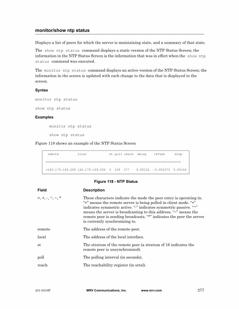
Displays a list of peers for which the server is maintaining state, and a summary of that state.
The show ntp status command displays a static version of the NTP Status Screen; the information in the NTP Status Screen is the information that was in effect when the show ntp status command was executed.
The monitor ntp status command displays an active version of the NTP Status Screen; the information in the screen is updated with each change to the data that is displayed in the screen.
Syntax
monitor ntp status
show ntp status
Examples
monitor ntp status
show ntp status
Figure 118 shows an example of the NTP Status Screen
Figure 118 - NTP Status
monitor/show ntp status
remote local st poll reach delay offset disp
========================================================================
=140.179.169.208 140.179.169.206 3 128 377 0.00122 -0.002373 0.00166
Field Description
=, +, -, ^, ~, * These characters indicate the mode the peer entry is operating in. “=” means the remote server is being polled in client mode. “+” indicates symmetric active. “-” indicates symmetric passive. “^” means the server is broadcasting to this address. “~” means the remote peer is sending broadcasts. “*” indicates the peer the server is currently synchronizing to.
remote The address of the remote peer.
local The address of the local interface.
st The stratum of the remote peer (a stratum of 16 indicates the remote peer is unsynchronized).
poll The polling interval (in seconds).
reach The reachability register (in octal).
451-0310P MRV Communications, Inc. www.mrv.com 277

monitor/show ntp status (continued)
delay The current estimated delay of the peer (in seconds).
offset The current estimated offset of the peer (in seconds).
disp The current estimated dispersion of the peer (in seconds).
278 MRV Communications, Inc. www.mrv.com 451-0310P
Disables (negates) specific features and boolean parameters on the LX unit. Refer to “Usage Guidelines” (below) for more information about using the no command in the Superuser command mode.
Syntax
no <feature_name>
Where Means
Usage Guidelines
The allowable arguments for this command consist of only those features and boolean parameters that can be set in the Superuser command mode and are currently enabled. To view the features and boolean parameters that are currently enabled, type the no command followed by a question mark (?).
Example
no pause
no
feature_name The name of the feature or boolean parameter that is to be disabled.
451-0310P MRV Communications, Inc. www.mrv.com 279
Sends a test message to Notification Users that have the specified facility/priority characteristics in their User Profiles. For more information on the facility/priority characteristics in User Profiles, refer to “Overview of User Profiles” in the LX-Series Configuration Guide.
Syntax
notify [facility <facil_char>] [priority <priority_char>] message <message_text>
Where Means
Usage Guidelines
The following are verified when a Notification user receives a test message:
• That syslogd is working
• That the user’s User Profile (and the Service Profile on which it is based) have been configured correctly
• That the Notification user has the connectivity that he or she needs to receive messages
Examples
notify facility daemon priority notice message This is a Test!
notify facility kern priority err message This is another Test!
notify facility user priority crit message This is still a Test!
notify facility user message This is the third-to-last Test!
notify priority err message This is the next-to-last Test!
notify message This is the last Test!
notify
facil_char Specifies the facility characteristic for the test message. The allowable values are authpriv, daemon, kern, syslog, user, local0, local1, local2, local3, local4, local5, local6, local7, and all. The default value is user. The test message will be sent to Notification users whose User Profiles match this facility characteristic and the specified priority characteristic.
priority_char Specifies the priority characteristic for the test message. The allowable values are emerg, alert, crit, err, notice, info, and warning. The default value is notice. The test message will be sent to Notification users whose User Profiles match this priority characteristic and the specified facility characteristic.
message_text A text string, of up to 80 characters, that specifies the test message.
280 MRV Communications, Inc. www.mrv.com 451-0310P

Reboots an outlet or turns an outlet on or off.
Syntax
outlet <power_master>:<outlet_number> on|off|reboot
Where Means
Examples
outlet 3:5 on
outlet 5:2 off
outlet 6:1 reboot
Displaying the State of an Outlet
The state of an outlet is displayed in the State column of the Device Screen for a POWER Port. An example of the Device Screen for an POWER Port appears in Figure 19 on page 84.
Use the monitor/show device status command to display the Device Screen for an POWER Port. Refer to “monitor/show device status” on page 83 for more information.
outlet
power_master Specifies the LX serial port from which the outlet is managed.
outlet_number Specifies an outlet on the IR-4800 or IR-5150 that is to be managed from the Power port.
The Power port number, combined with the outlet number, uniquely identifies each outlet. For example, 2:5 identifies Outlet 5 on the device that is managed from LX serial port 2.
on Turn the outlet on.
off Turn the outlet off.
reboot Reboot the outlet.
451-0310P MRV Communications, Inc. www.mrv.com 281
Reboots, or turns on or off, all of the outlets in an outlet group.
Syntax
outlet group <group_number>|<group_name> on|off|reboot
Where Means
Examples
outlet group 5 reboot
outlet group Laboutlets off
outlet group 6 on
Displaying the State of Outlet Groups
The state of an outlet group (On, Off, or Reboot) is displayed in the State column of the Outlet Group Status Screen. An example of the Outlet Group Status Screen appears in Figure 65 on page 150.
Use the monitor/show outlet group status command to display the Outlet Group Status Screen. Refer to “monitor/show outlet group status” on page 150 for more information.
outlet group
group_number An integer number that specifies an existing outlet group.
group_name The descriptive name of an existing outlet group.
on Turn the outlets in the group on.
off Turn the outlets in the group off.
reboot Reboot the outlets in the group.
282 MRV Communications, Inc. www.mrv.com 451-0310P
Configures the screen to pause after displaying the number of lines specified in the “lines/screen” value for the terminal.
Syntax
pause enable
Example
pause enable
Displaying the State of the Pause Feature
The state of the Pause Feature (Enabled/Disabled) is displayed in the Screen Pause field of the Subscriber Characteristics Screen. An example of the Subscriber Characteristics Screen appears in Figure 93 on page 203.
Use the monitor/show subscriber command to display the Subscriber Characteristics Screen. Refer to “monitor/show subscriber” on page 202 for more information.
pause enable
451-0310P MRV Communications, Inc. www.mrv.com 283

Sends a series of 4 echo messages to a destination host.
Syntax
ping [ipv6] [<ip_address or ipv6_address>|NAME]
Where Means
Usage Guidelines
If a destination host is not specified, the echo message is sent to the default destination host which is your Preferred Service. Refer to the preferred service command on page 676 for information on configuring a Preferred Service.
If the ping command is executed without a destination host, and you do not have a Preferred Service configured, the following error message is displayed:
No Preferred Service Configured
Examples
ping 119.20.112.3
ping
ping FinanceServer
ping ipv6 fe80::220:edff:fe4B:sc67
Displaying Your Preferred Service
Your Preferred Service is displayed in the Preferred Service field of the Subscriber Characteristics Screen. An example of the Subscriber Characteristics Screen appears in Figure 93 on page 203.
Use the monitor/show subscriber command to display the Subscriber Characteristics Screen. Refer to “monitor/show subscriber” on page 202 for more information.
ping
ipv6 Indicates the following address is IPv6, not IPv4.
ip_address or ipv6_address
The IP Address of the destination host. (See “Usage Guidelines” (below) for the default value of this field.)
NAME The domain name of the destination host. (See “Usage Guidelines” (below) for the default value of this field.)
284 MRV Communications, Inc. www.mrv.com 451-0310P

Re-starts the LX unit.
Syntax
reload
Usage Guidelines
If the LX parameter set has been saved since the last time the LX unit was re-started, or since the last configuration change was made, the LX unit will be re-started immediately. If the LX parameters have not been saved, you will be prompted to save them before the LX is re-started.
Configuration is not saved!!! Proceed anyway? (y/n) :
Enter y to re-start the LX unit without saving the changes.
Enter n to abort the command.
Refer to “save configuration” on page 291 for more information on saving the LX parameters.
Example
reload
reload
451-0310P MRV Communications, Inc. www.mrv.com 285
Regenerates the Notification configuration files and re-starts syslogd.
NOTE: It is recommended that you execute this command after you configure the Notification Feature with Multi-Level Command Execution. For more information on Multi-Level Command Execution, refer to “Multi-Level Command Execution” on page 1095.
Syntax
restart notification
Usage Guidelines
The restart notification command regenerates the notification configuration and re-starts syslogd. It is necessary to do this when you configure the Notification Feature from outside of the Notification context. (You are outside of the Notification context when you configure the Notification Feature from outside of the Notification command mode or one of its subordinate command modes.)
Example
restart notification
restart notification
286 MRV Communications, Inc. www.mrv.com 451-0310P

Executes the rlogin connection and enables rlogin host parameters.
Syntax
rlogin [<host_name> | <ip_address>]
Where Means
Usage Guidelines
Enter rlogin only when you want to execute the rlogin connection.
Use this command when you want to enable the following parameters: uses -1, dynamic subscriber name, and typed in host_name or ip_address . This command is disabled by default. This is a User as well as a Superuser command.
Examples
rlogin
rlogin a123456
rlogin 166.133.222.16
rlogin host
<host_name> The domain name of the destination host.
<ip_address> The IP address of the destination host.
451-0310P MRV Communications, Inc. www.mrv.com 287

Enables rlogin transparent parameters and transparent host parameters.
Syntax
rlogin transparent [<host_name> | <ip_address>]
Where Means
Usage Guidelines
Use this command when you need full data transparency in an rlogin session. Enter rlogin transparent when you want to enable rlogin transparent parameters only. This command is disabled by default. This is a User as well as a Superuser command.
NOTE: When you are in transparent mode, using the forward, backward, and local switch control sequences have no effect, as these sequences may be part of a binary file. Therefore, you cannot switch between sessions until you exit the current rlogin session.
NOTE: rlogin with full transparency is not supported in the shell. If you are running rlogin from the shell with the –8EL option, the LX will not pass non-ascii characters to the connection partner.
Example
rlogin transparent
rlogin transparent a123456
rlogin transparent 166.133.222.16
rlogin transparent host
<host_name> The domain name of the destination host.
<ip_address> The IP address of the destination host.
288 MRV Communications, Inc. www.mrv.com 451-0310P

Invokes the rlogin protocol, and will pass a specified usernameto teh target host.
Syntax
rlogin username <user_name> [<host_name> |<ip_address>]
Where Means
Usage Guidelines
Enter rlogin username <user_name> when you want to pass a username that is known to the destination host.
Use this command when you want to enable the following parameters: uses -1, typed in user_name, and typed in host_name or ip_address. This command line is useful when you intend to login to the destination host using a username different than the subscriber name you initially logged into the LX unit. The rlogin protocol is disabled by default. This is a User as well as a Superuser command.
Example
rlogin username tim
rlogin username tim a123456
rlogin user 166.122.160.12
rlogin username host
<user_name> The user name to be passed to the target host.
<host_name> The domain name of the destination host.
<ip_address> The IP address of the destination host.
451-0310P MRV Communications, Inc. www.mrv.com 289

Invokes the rlogin protocol, passes a specified username to the target host, and establishes the rlogin session in transparent mode.
Syntax
rlogin username <user_name> transparent [<host_name> |<ip_address>]
Where Means
Usage Guidelines
Enter rlogin username <user_name> transparent when you want to enable rlogin user transparent parameters only.
Use this command when you need full data transparency in an rlogin session. This command is disabled by default. This is a User as well as a Superuser command.
NOTE: When you are in transparent mode, using the forward, backward, and local switch control sequences have no effect, as these sequences may be part of a binary file. Therefore, you cannot switch between sessions until you exit the current rlogin session. Software flow control charactersare also passed as data.
NOTE: rlogin with full transparency is not supported in the shell. If you are running rlogin from the shell with the –8EL option, the LX will not pass non-ascii characters to the connection partner.
Examples
rlogin username tim transparent
rlogin user tim transparent a123456
rlogin user tim transparent 160.145.120.33
rlogin username transparent host
<user_name> The user name to be passed to the target host.
<host_name> The domain name of the destination host.
<ip_address> The IP address of the destination host.
290 MRV Communications, Inc. www.mrv.com 451-0310P

Saves the configuration of the LX unit to the local flash or to a network parameter server.
Syntax
save configuration flash|[network <filename> <domain_name>|<ip_address>]
Where Means
Examples
save configuration flash
save config network unit1 119.25.42.37
Displaying the Configuration Status, Server, and Filename
The configuration status, server, and filename are displayed in the following fields of the System Status Screen:
save configuration
flash Save the LX-unit configuration to the local flash.
network Save the LX-unit configuration to a network parameter server.
filename Identifies the network file to which the LX-unit configuration is to be saved. The filename will be appended with a .zip suffix. For example, unit1 is a valid filename. The file that exists on the load server appears as unit1.boston.zip.
domain_name Specifies the domain name of the TFTP server to which the LX-unit configuration is to be saved.
ip_address Specifies the IP Address of the TFTP server to which the LX-unit configuration is to be saved.
Configuration Status Indicates whether or not the LX configuration has been saved.
Configuration Load From Indicates whether the LX configuration is loaded from local flash or from a TFTP server. If the LX configuration is loaded from a TFTP server, this field contains the IP address, or domain name, of the TFTP server.
Configuration Settings to Boot From
Indicates whether the configuration of the LX unit is booted from the local flash or from the network.
Configuration Version The version number of the LX configuration. This number is incremented by 1 each time a modified version of the LX configuration is saved.
Configuration Conversion Status
The LX version to which the existing configuration was converted.
451-0310P MRV Communications, Inc. www.mrv.com 291

An example of the System Status Screen appears in Figure 100 on page 218.
Use the monitor/show system status command to display the System Status Screen. Refer to “monitor/show system status” on page 218 for more information.
save configuration (continued)
Network File Name The network file to which the LX configuration was saved.
292 MRV Communications, Inc. www.mrv.com 451-0310P
Executes a script file that contains LX CLI commands.
Syntax
script <filename>
Where Means
Usage Guidelines
The script command allows you to execute multiple LX commands by running one script.
The LX Script file is an ASCII file that can contain the following kinds of entries:
• Commands from the Superuser Command Mode of the LX CLI
• Multi-level commands in which the mode-access portion of the command begins with the configuration command. For more information on multi-level commands, refer to “Multi-Level Command Execution” on page 1095.
The LX script file is stored in the /config/ directory on the LX unit.
The following is an example of an LX Script file called TurnOffAndDenyAccess.txt:
outlet 5:2 offoutlet 5:5 offoutlet 6:2 offoutlet 7:2 offconfiguration subscriber GeorgeJ no access outlet allconfiguration subscriber TomW no access outlet allconfiguration subscriber JackC no access outlet alllogout GeorgeJlogout TomWlogout JackC
Example
script TurnOffAndDenyAccess.txt
script
filename The name of an LX script file.
451-0310P MRV Communications, Inc. www.mrv.com 293
Sends a text message, within an SNMP trap, to all configured SNMP trap clients of the LX unit.
Syntax
send trap message <text_string>
Where Means
Usage Guidelines
In order to send an SNMP trap with this command, SNMP must be enabled for the LX and SNMP trap clients must be configured for the LX. Refer to “snmp enable” on page 385 to enable SNMP for the LX. Refer to “trap client” on page 705 to configure SNMP trap clients for the LX unit.
Example
send trap message This is a Test of SNMP on FinanceServer
send trap message
text_string The text message that is to be sent to the configured SNMP trap clients. This can be an ASCII string of up to 80 characters.
294 MRV Communications, Inc. www.mrv.com 451-0310P

Runs the setup utility (Quick Start Configurator). For more information on the Quick Start Configurator, refer to the LX Quick Start Instructions.
NOTE: You can not execute the setup command from a remote connection to the LX unit. You can only execute the setup command from a direct serial connection to the LX unit.
Syntax
setup
Example
setup
setup
451-0310P MRV Communications, Inc. www.mrv.com 295

Enters the Built-in Linux shell on the LX unit.
Syntax
shell
Usage Guidelines
When this command is executed, the following is displayed on the Linux monitor:
BusyBox v0.60.1 (2003.06.16-12:27+0000) Built-in shell (ash)
Enter ‘help’ for a list of built-in commands
InReach:/#
You can enter any command in the Built-in Linux shell from the command prompt (InReach:/# in the above example). Enter help at the command prompt for a list of the built-in commands.
The format of the command prompt is <username>:/#, where <username> is the username of the subscriber.
Enter exit at the command prompt to return to Superuser Mode.
Example
shell
shell
296 MRV Communications, Inc. www.mrv.com 451-0310P

Specifies a shell level command to run from the CLI, without having to drop to the shell first.
Syntax
shell command <shell_command>
Where Means
Example
shell command cat /var/log/syslog
shell command
shell_command The shell level command to be executed from the CLI.
451-0310P MRV Communications, Inc. www.mrv.com 297
Opens a Secure Shell (Triple-DES/BLOWFISH) connection.
NOTE: In order to open a Secure Shell connection, you must have SSH enabled for your subscriber account. For more information, refer to “Verifying That You Have SSH Enabled” (below).
Syntax
ssh [ipv6] [<ip_address or ipv6_address> [NUMBER]]|[NAME [NUMBER]]
[LOGIN NAME]
Where Means
Usage Guidelines
The default SSH server is your Preferred Service. Refer to the preferred service command on page 676 for information on configuring a Preferred Service.
If the ssh command is executed without an SSH server, and you do not have a Preferred Service configured, the following error message is displayed:
No Preferred Service Configured
Examples
ssh 102.19.240.14
ssh 102.19.240.14 2322
ssh 102.19.240.14 2322 henryh
ssh ipv6 fe80::220:edff:fe4B:sc67
Verifying That You Have SSH Enabled
If SSH is enabled for your subscriber account, it will be listed, with the other enabled protocols, in the lower right-hand corner of the Subscriber Characteristics Screen. An example of the Subscriber Characteristics Screen appears in Figure 93 on page 203.
Use the monitor/show subscriber command to display the Subscriber Characteristics Screen. Refer to “monitor/show subscriber” on page 202 for more information.
ssh
ipv6 Indicates the following address is IPv6, not IPv4.
ip_address or ipv6_address
The IP Address of the SSH server to which the connection is being made. (See “Usage Guidelines” (below) for the default value of this field.)
NAME The Domain Name of the SSH server to which the connection is being made. (See “Usage Guidelines” (below) for the default value of this field.)
NUMBER The socket number to which the connection is being made.
LOGIN NAME The name that you are using to log in to the SSH server.
298 MRV Communications, Inc. www.mrv.com 451-0310P
Opens a Telnet connection to a host.
NOTE: In order to open a Telnet connection, you must have Telnet enabled for your subscriber account. For more information, refer to “Verifying That You Have Telnet Enabled” (below).
Syntax
telnet [ipv6] [<ip_address or ipv6_address> [NUMBER]]|[NAME
[NUMBER]] [<window_size>]
Where Means
Usage Guidelines
The default Telnet host is your Preferred Service. Refer to the preferred service command on page 676 for information on configuring a Preferred Service.
If the telnet command is executed without a Telnet host, and you do not have a Preferred Service configured, the following error message is displayed:
No Preferred Service Configured
Examples
telnet 102.19.240.14
telnet 102.19.240.14 2500 1200
telnet
telnet ipv6 fe80::220:edff:fe4B:sc67
Verifying That You Have Telnet Enabled
If Telnet is enabled for your subscriber account, it will be listed, with the other enabled protocols, in the lower right-hand corner of the Subscriber Characteristics Screen. An example of the Subscriber Characteristics Screen appears in Figure 93 on page 203.
Use the monitor/show subscriber command to display the Subscriber Characteristics Screen. Refer to “monitor/show subscriber” on page 202 for more information.
telnet
ipv6 Indicates the following address is IPv6, not IPv4.
ip_address or ipv6_address
The IP Address of the Telnet host. (See “Usage Guidelines” (below) for the default value of this field.)
NAME The Domain Name of the Telnet host. (See “Usage Guidelines” (below) for the default value of this field.)
NUMBER The socket number to which the connection is being made.
window_size An integer number between 128 and 1400 that specifies the TCP window size for the Telnet connection. The default value is 1400.
451-0310P MRV Communications, Inc. www.mrv.com 299

Sets the terminal type for the LX user.
Syntax
terminal <terminal_type>
Where Means
Example
terminal vt100
terminal ansi
Displaying the Terminal Type
The terminal type is displayed in the Configured TermType field of the Subscriber Status Screen. An example of the Subscriber Status Screen appears in Figure 94 on page 205.
Use the monitor/show subscriber command to display the Subscriber Status Screen. Refer to “monitor/show subscriber” on page 202 for more information.
terminal
terminal_type The terminal type for the LX unit. The allowable terminal types are VT100 and ANSI.
300 MRV Communications, Inc. www.mrv.com 451-0310P
Updates the LX software or ppciboot file from a TFTP server on the network.
Syntax
update software|ppciboot [<tftp_server>]
Where Means
Usage Guidelines
In order for this command to take effect, you must restart the LX unit by executing the reload command. The reload command is described on page 285.
If this command is executed without a TFTP server specified, and there is no default TFTP server configured, the following error message is displayed:
No TFTP HostDownload Failed
Examples
update ppciboot 102.19.169.141
update software 102.19.169.141
update ppciboot
update software
update
software Update the LX software from the specified TFTP server.
ppciboot Update the LX ppciboot file from the specified TFTP server.
tftp_server The IP Address or the Domain Name of the TFTP server from which the LX software or ppciboot file is to be copied. If this field is not specified, the default TFTP server is used. To display the default TFTP server, refer to “monitor/show system characteristics” on page 211.
451-0310P MRV Communications, Inc. www.mrv.com 301

Erases the statistics data for the LX unit.
Syntax
zero all
Example
zero all
zero all
302 MRV Communications, Inc. www.mrv.com 451-0310P

Clears the databuffer of a port.
Syntax
zero databuffer port async <port_number>
Where Means
Example
zero databuffer port async 2
zero databuffer port async
<port_number> The number of the port on which you want to zero the databuffer.
451-0310P MRV Communications, Inc. www.mrv.com 303

Resets the log files for the LX unit.
Syntax
zero log
Example
zero log
zero log
304 MRV Communications, Inc. www.mrv.com 451-0310P
Deletes from the LX unit the SecurID Secret that was sent from the SecurID server.
Syntax
zero securid secret
Example
zero securid secret
Displaying the Status of the SecurID Secret
The status of the SecurID secret for the LX unit is displayed in the Learned SecurID Node Secret field of the SecurID Status Screen. (When the content of the Learned SecurID Node Secret field is False, it means that the SecurID secret has been deleted.) An example of the SecurID Status Screen appears in Figure 82 on page 185.
Use the monitor/show securid status command to display the SecurID Characteristics Screen. Refer to “monitor/show securid status” on page 185 for more information.
zero securid secret
451-0310P MRV Communications, Inc. www.mrv.com 305

306 MRV Communications, Inc. www.mrv.com 451-0310P

Chapter 3
Configuration Commands
The Configuration commands are executed in the Configuration command mode. When the LX unit is in the Configuration command mode, the Configuration command prompt (i.e., Config:0 >>) is displayed on the terminal screen.
The format of the Configuration command prompt is as follows:
Config:<session_number> >>
where <session_number> is the session number of the current connection.
To enter the Configuration command mode, do one of the following:
• If you are in the Superuser command mode, execute the configuration command. This displays the configuration prompt.
Refer to page 254 for more information on the configuration command.
• If you are in the Interface, Ethernet, Subscriber, Asynchronous, Menu, Menu Editing, Notification, or Broadcast Groups command mode, execute the exit command until the Configuration command prompt is displayed.
451-0310P MRV Communications, Inc. www.mrv.com 307
Enters the Authentication, Accounting, and Authorization (AAA) command mode. In the AAA command mode, you configure server-based authentication, accounting, and authorization methods for the LX unit. For more information on the AAA command mode, refer to “Authentication, Accounting, and Authorization Commands” on page 403.
NOTE: The server-based methods for authentication, accounting, and authorization methods are RADIUS, SecurID, and TACACS+.
Syntax
aaa
Example
aaa
aaa
308 MRV Communications, Inc. www.mrv.com 451-0310P
Enables the digital signature authentication, even if you are not in FIPS mode.
Syntax
authenticate image enable
Example
authenticate image enable
no authenticate image
Displaying the State of the Authenticate Image
The state of the Authenticate Image (Enabled/Disabled) is displayed on the System Characteristics Screen. An example of the System Characteristics Screen appears in Figure 97 on page 211.
Use the monitor/show system characteristics command to display the System Characteristics Screen. Refer to “monitor/show system characteristics” on page 211 for more information.
authenticate image enable
451-0310P MRV Communications, Inc. www.mrv.com 309
Configures the LX unit to boot the configuration from the local flash.
Syntax
boot configuration from flash
Example
boot configuration from flash
Verifying That the LX Unit Is Booted from the Local Flash
The Software Load From field on the System Status Screen indicates whether the LX unit is booted from the local flash. An example of the System Status Screen appears in Figure 100 on page 218.
Use the monitor/show system status command to display the System Status Screen. Refer to “monitor/show system status” on page 218 for more information.
boot configuration from flash
310 MRV Communications, Inc. www.mrv.com 451-0310P
Configures the LX unit to boot from a local file on the LX unit.
Syntax
boot configuration from name <filename>
Where Means
NOTE: You can use the monitor/show system status command to display the name of the boot file. The monitor/show system status command is described on page 218.
Example
boot configuration from name local.prm
Displaying the Name of the Local Boot File
The name of the local boot file is displayed in the Configuration File to Boot From field on the System Status Screen. An example of the System Status Screen appears in Figure 100 on page 218.
Use the monitor/show system status command to display the System Status Screen. Refer to “monitor/show system status” on page 218 for more information.
boot configuration from name
filename The name of the local (LX-based) from which the LX unit will be booted. The filename may include a suffix. For example, the default filename is config.prm.
451-0310P MRV Communications, Inc. www.mrv.com 311
Configures the LX unit to boot from a TFTP server.
Syntax
boot configuration from network <ip_address> <filename>
Where Means
Example
boot configuration from network 119.25.42.37 new_image
Displaying the Configuration Server and Filename
The configuration server and filename are displayed in the following fields of the System Status Screen:
Configuration Load From If the LX configuration is loaded from a TFTP server, this field contains the IP address, or domain name, of the TFTP server.
Network File Name The network file to which the LX configuration was saved.
An example of the System Status Screen appears in Figure 100 on page 218.
Use the monitor/show system status command to display the System Status Screen. Refer to “monitor/show system status” on page 218 for more information.
boot configuration from network
ip_address Specifies the IP Address of the TFTP server from which the LX unit is to be booted.
filename The file on the LX unit, or on the TFTP server, from which the LX unit will be booted. The filename will be appended with a .zip suffix on the tftp server when it is saved. For example, local and local.zip are valid filenames.
312 MRV Communications, Inc. www.mrv.com 451-0310P
Sets the time for the LX system clock.
NOTE: Use the date command to set the date for the system calendar. For more information, refer to “date” on page 317.
Syntax
clock HH:MM[:SS]
Where Means
Examples
clock 14:47
clock 04:29:11
Displaying the Time for the LX System Clock
The Clock Screen shows the time for the LX system clock. An example of the Clock Screen appears in Figure 3 on page 63.
Use the monitor/show clock command to display the Clock Screen. Refer to “monitor/show clock” on page 63 for more information.
clock
HH The hour in 24-hour format; for example, 23.
MM The minute; for example, 09.
SS The second; for example, 02.
451-0310P MRV Communications, Inc. www.mrv.com 313

Enters the Cluster command mode. The Cluster command prompt (e.g., Cluster:0 >>) is displayed while you are in the Cluster command mode. For more information, refer to “Cluster Configuration and Control Commands” on page 1003.
Syntax
cluster
Example
Config:0>>cluster
Cluster:0>>cluster
cluster
314 MRV Communications, Inc. www.mrv.com 451-0310P
Copies the configuration of one LX port to another LX port, or to a range of LX ports.
Syntax
copy port <origin_port> to <destination_list>
Where Means
Usage Guidelines
You can not copy a port configuration to, or from, a port that is configured for SENSOR or POWER access.
Examples
copy port 3 to 6
copy port 2 to 5 7
copy port 3 to 8-11,13,15,16
copy port
origin_port The LX port from which the configuration is to be copied.
destination_port1 The first port in a range of LX ports to which the configuration is to be copied. (Note: If destination_portn is not specified, the configuration is copied only to destination_port1.)
destination_list Specifies the port(s) to which the configuration is to be copied. If you specify more than one port in the destination_list, the ports must be separated by a comma; for example, 5,6,8,10. You can specify a range of ports by placing a hyphen between the first port and last port in the range; for example, 12-15.
451-0310P MRV Communications, Inc. www.mrv.com 315
Copies the configuration of one LX subscriber to one, or several, LX subscribers. If the destination subscriber is not in the database, a new subscriber is created.
NOTE: When you create a new subscriber with the copy subscriber command, all subscriber characteristics are copied over except the user password, user prompt, menu name, and web menu name.
Syntax
copy subscriber <origin_subscriber> to <destination_subscriber>*
Where Means
Usage Guidelines
The maximum number of subscribers on an LX unit is equal to double the number of ports on the unit. For example, the maximum number of subscribers is 16 on an 8-port unit, 32 on a 16-port unit, 64 on a 32-port unit, and 96 on a 48-port unit.
Examples
copy subscriber benw to jimk billj edw susano emilyc
copy subscriber mark to bill
copy subscriber
origin_subscriber The LX subscriber from which the configuration is to be copied.
destination_subscriber The subscribers to which the configuration of origin_subscriber is to be copied.
Note: If you specify an existing subscriber in this field, the origin_subscriber configuration overwrites the destination_subscriber.
316 MRV Communications, Inc. www.mrv.com 451-0310P

Sets the date for the LX system calendar.
NOTE: Use the clock command to set the system clock for the LX unit. For more information, refer to “clock” on page 313.
Syntax
date MM/DD[/YYYY]
Where Means
Example
date 03/17/2002
NOTE: In the above example, the date is set to March 17, 2002.
Displaying the Date for the LX System Calendar
The Clock Screen shows the date for the LX system calendar. An example of the Clock Screen appears in Figure 3 on page 63.
Use the monitor/show clock command to display the Clock Screen. Refer to “monitor/show clock” on page 63 for more information.
date
MM/DD[/YYYY] The date for the LX system calendar, where
MM = The month; for example, 03 for March.
DD = The date; for example, 17 for the 17th.
YYYY = The 4-digit year; for example, 2002.
451-0310P MRV Communications, Inc. www.mrv.com 317

Resets the boot file for the LX unit to the default boot file.
When this command is entered the following message is displayed:
File Saved
Syntax
default boot
Example
default boot
Displaying the Boot file for the LX Unit
The boot file for the LX unit is displayed in the Configuration File to Boot From field of the System Status Screen. An example of the System Status Screen appears in Figure 100 on page 218.
Use the monitor/show system status command to display the System Status Screen. Refer to “monitor/show system status” on page 218 for more information.
default boot
318 MRV Communications, Inc. www.mrv.com 451-0310P
Resets the configuration of the LX unit to default values and then shuts down and re-starts the LX unit.
Syntax
default configuration
Usage Guidelines
When this command is entered, the following confirmation prompt is displayed:
Do You Really want to default the unit? [y|n] :
Entering “y” will reset the configuration. The system will automatically re-start when you enter “y”.
Entering “n” will abort the command.
Example
default configuration
default configuration
451-0310P MRV Communications, Inc. www.mrv.com 319
Resets the sizes of log files on the LX unit to the default value.
Syntax
default log size
Example
default log size
Displaying the Size of Logging Files on the LX Unit
The size of logging files on the LX unit is displayed in the Logging Size field of the System Characteristics Screen. An example of the System Characteristics Screen appears in Figure 97 on page 211.
Use the monitor/show system characteristics command to display the System Characteristics Screen. Refer to “monitor/show system characteristics” on page 211 for more information.
default log size
320 MRV Communications, Inc. www.mrv.com 451-0310P

Resets the off time for an outlet group to the default value of 10 seconds.
Syntax
default outlet group <group_number>|<group_name> off time
Where Means
Examples
default outlet group 2 off time
default outlet group rmlights off time
Displaying the Outlet Group Off Time
The off time for an outlet group is displayed in the Group Off Time field of the Outlet Group Status Screen. An example of the Outlet Group Status Screen appears in Figure 65 on page 150.
Use the monitor/show outlet group status command to display the Outlet Group Status Screen. Refer to “monitor/show outlet group status” on page 150 for more information.
default outlet group off time
group_number An integer number that identifies the group whose off time is being reset to the default value.
group_name The name assigned to the outlet group.
451-0310P MRV Communications, Inc. www.mrv.com 321

Resets the ppciboot password for the LX unit to the default value.
Syntax
default ppciboot password
Example
default ppciboot password
default ppciboot password
322 MRV Communications, Inc. www.mrv.com 451-0310P
Resets the timeout or retry value for the TFTP server to its default value.
Syntax
default tftp timeout|retry
Where Means
Examples
default tftp timeout
default tftp retry
Displaying the Timeout and Retry Values for the TFTP Server
The TFTP timeout and retry values are displayed on the System Characteristics Screen. An example of the System Characteristics Screen appears in Figure 97 on page 211.
Use the monitor/show system characteristics command to display the System Characteristics Screen. Refer to “monitor/show system characteristics” on page 211 for more information.
default tftp
timeout Reset the TFTP server timeout to its default value of 3 seconds.
retry Reset the TFTP server retries to its default value of 3.
451-0310P MRV Communications, Inc. www.mrv.com 323

Specifies the domain name of the LX unit.
Syntax
domain name NAME
Where Means
Usage Guidelines
The portion of the domain name that follows the period is the domain name suffix. For example, com is the suffix in the domain name boston_office.com.
Example
domain name boston_office.com
Displaying the Domain Name
The Domain Name is displayed in the Domain Name Suffix field on the System Characteristics Screen. An example of the System Characteristics Screen appears in Figure 97 on page 211.
Use the monitor/show system characteristics command to display the System Characteristics Screen. Refer to “monitor/show system characteristics” on page 211 for more information.
domain name
NAME The domain name for the LX unit. The domain name should include a period (.) and a suffix.
324 MRV Communications, Inc. www.mrv.com 451-0310P

When the end command is issued in the Configuration Command Mode, it returns the user to the Superuser command mode.
Syntax
end
Usage Guidelines
The end command can be issued in all of the LX command modes except for User and Superuser. Executing the end command always returns the user to the Superuser command mode.
Example
end
end
451-0310P MRV Communications, Inc. www.mrv.com 325
Returns the user to the previous command mode. For example, if the current command mode is Configuration, issuing this command will return the user to the Superuser command mode.
Syntax
exit
Usage Guidelines
The exit command can be issued in all of the LX command modes. However, the effect of the exit command varies, depending on the command mode from which it is issued.
As noted above, issuing the exit command in the Configuration command mode returns the user to the previous command mode. The same goes for issuing the exit command in any command mode other than User. For example, issuing the exit command in the Interface command mode returns the user to the Configuration command mode; issuing the exit command in the Menu Editing command mode returns the user to the Menu command mode, and so on.
Issuing the exit command in the User command mode exits the LX CLI and closes the connection to the LX unit.
Example
exit
exit
326 MRV Communications, Inc. www.mrv.com 451-0310P
Enables the finger daemon (fingerd) for exchanging information between hosts about users who are logged on to the LX unit.
Syntax
fingerd enable
Example
fingerd enable
Displaying the State of the Finger Daemon
The state of the finger daemon (Enabled/Disabled) is displayed on the System Characteristics Screen. An example of the System Characteristics Screen appears in Figure 97 on page 211.
Use the monitor/show system characteristics command to display the System Characteristics Screen. Refer to “monitor/show system characteristics” on page 211 for more information.
fingerd enable
451-0310P MRV Communications, Inc. www.mrv.com 327

Configures the network gateway IP address for the LX unit.
Syntax
gateway A.B.C.D
Where Means
Example
gateway 119.20.112.47
Displaying the Gateway IP Address
The gateway IP address of the LX unit is displayed in the Gateway field of the System Characteristics Screen. An example of the System Characteristics Screen appears in Figure 97 on page 211.
Use the monitor/show system characteristics command to display the System Characteristics Screen. Refer to “monitor/show system characteristics” on page 211 for more information.
gateway
A.B.C.D The IP Address of the router/gateway that is to be used as the default route for the LX unit.
328 MRV Communications, Inc. www.mrv.com 451-0310P
Configures a network name for the LX unit.
Syntax
hostname NAME
Where Means
Examples
hostname boston_office
hostname a123456
Displaying the Network Name of the LX Unit
The network name of the LX unit is displayed in the Name field of the System Characteristics Screen. An example of the System Characteristics Screen appears in Figure 97 on page 211.
Use the monitor/show system characteristics command to display the System Characteristics Screen. Refer to “monitor/show system characteristics” on page 211 for more information.
hostname
NAME A text string of up to 15 alphanumeric characters that specifies the network name for the LX unit.
451-0310P MRV Communications, Inc. www.mrv.com 329
Enters the Interface command mode. In the Interface command mode, the user can create or change an interface record. For more information on the Interface command mode, refer to “Interface Commands” on page 483.
Syntax
interface NUMBER
Where Means
Example
interface 1
interface
NUMBER Specifies an interface number. In the Interface command mode, you can configure the characteristics of the IP interface that is associated with this interface number. The maximum number of IP interfaces is the number of serial ports on the LX unit, plus 2. For example, the maximum number of IP interfaces on an 8-port unit is 11 or 12 (if the unit has a modem port); the maximum number of IP interfaces on an 16-port unit is 20, and so on.
On LX-8000 units, the maximum number of IP interfaces is the number of serial ports on the LX unit, multiplied by the number of Ethernet ports (2), plus 2. For example, the maximum number of IP interfaces on a 42-port unit is 86.
If the IP interface does not exist, it is created when this command is executed.
330 MRV Communications, Inc. www.mrv.com 451-0310P

Configures ip6tables according to the information given in the <string>.
Syntax
ip6tables <string>
Where Means
Example
ip6tables -A INPUT -s fe80::220:edff:febe:3cae -j DROP
Displaying the IP6 Tables Information
The IP6 Tables information is displayed in the IP6 Tables Screen. An example of the IP6 Tables Screen appears in Figure 49 on page 132.
Use the monitor/show ip6tables command to display the IP6 Tables Screen. Refer to for “monitor/show ip6tables” on page 132 more information.
ip6tables
<string> Standard ip6table syntax which passes the string directly to the “iptables” executable. Refer to Appendix D in the LX-Series Configuration Guide for further information on ip6tables.
451-0310P MRV Communications, Inc. www.mrv.com 331

Configures iptables according to the information given in the <string>.
NOTE: There is no context help with this command. The string is sent and executed by iptables at the shell. If an error occurs, the error is returned to the CLI to notify the user.
Syntax
iptables <string>
Where Means
Example
iptables -A INPUT -s 10.128.1.11 -j DROP
Displaying the IP Tables Information
The IP Tables information is displayed in the IP Tables Screen. An example of the IP Tables Screen appears in Figure 50 on page 133.
Use the monitor/show iptables command to display the IP Tables Screen. Refer to “monitor/show iptables” on page 133 for more information.
iptables
<string> Standard iptable syntax which passes the string directly to the “iptables” executable. Refer to Appendix D in the LX-Series Configuration Guide for further information on iptables.
332 MRV Communications, Inc. www.mrv.com 451-0310P

Adds or deletes a static neighbor for the destination <ipv6_address> whose ethernet address is the <ethernet_address> of the specified ethernet device. Enter no ipv6 neighbor address <ipv6_address_of_neighbor> lladdr <eth_address_of_neighbor>
device <ethernet_device> to delete a neighbor address.
Syntax
ipv6 neighbor address <ipv6_address_of_neighbor> lladdr
<eth_address_of_neighbor> device <ethernet_device>
Where Means
Example
ipv6 neighbor address fe80::220:edff:febe:3cae lladdr 00:20:ed:be:3c:ae device eth0
no ipv6 neighbor address fe80::220:edff:febe:3cae lladdr 00:20:ed:be:3c:ae device eth0
Displaying the IPv6 Neighbor Addresses
The IPv6 Neighbor Addresses are displayed in the IPv6 Neighbors Screen. An example of the IPv6 Neighbors Screen appears in Figure 51 on page 134.
Use the monitor/show ipv6 neighbor device ethx command to display the IPv6 Routes Screen. Refer to “monitor/show ipv6 neighbor device ethx” on page 134 for more information.
ipv6 neighbor address
ipv6_address_of_neighbor
The address of the neighbor you want to permanently configure as the neighbor.
eth_address_of_neighbor
The corresponding ethernet address of the above defined neighbor.
ethernet_device
Set to any configured interface.
451-0310P MRV Communications, Inc. www.mrv.com 333

Adds or deletes a static route for the <ipv6 address/prefixLength> via <ipv6 address> for the specified ethernet device. “Via” is the IPv6 term for Gateway. Use this parameter when you want communication with the IPv6 internet. If “via” is left out, the route entered is through the specified interface. Enter no ipv6 address <ipv6 address/prefixLength> device <ethernet_device> via <ipv6_address> to delete a route address.
Syntax
ipv6 route address <ipv6 address/prefixLength> device
<ethernet_device> via <ipv6_address>
Where Means
Examples
ipv6 route address 3ffe:303:14:42a0:9cff:fe00:8ad/64 device eth0 via 3ffe:303:14:42a0:9cff:fe00:8ac
no ipv6 route address 3ffe:303:14:42a0:9cff:fe00:8ad/64 device eth0 via 3ffe:303:14:42a0:9cff:fe00:8ac
Displaying the IPv6 Route Addresses
The IPv6 Route Addresses are displayed in the IPv6 Routes Screen. An example of the IPv6 Routes Screen appears in Figure 52 on page 135.
Use the monitor/show ipv6 routes device ethx command to display the IPv6 Routes Screen. Refer to “monitor/show ipv6 routes device ethx” on page 135 for more information.
ipv6 route address
ipv6_address/prefixLength
The address you want to route.
ethernet_device Set to any configured interface.
ipv6_address The address that will route the above defined address.
334 MRV Communications, Inc. www.mrv.com 451-0310P

Defaults the value for the packet TTL used in tunnelling. The default is 255.
Syntax
ipv6 tunnel <tunnel_name> default ttl
Where Means
Example
ipv6 tunnel rem-6to4 default ttl
Usage Guidelines
The tunnel must already be set up on the interface.
Displaying Information for Tunnel TTL
The Tunnel TTL is displayed in the Tunnel TTL field of the IPv6 Tunnel Information Screen. An example of the IPv6 Tunnel Information Screen appears in Figure 53 on page 136.
Use the monitor/show ipv6 tunnel all|<tunnel_name> command to display the IPv6 Tunnel Information Screen. Refer to “monitor/show ipv6 tunnel” on page 136 for more information.
ipv6 tunnel default ttl
tunnel_name The unique name of the tunnel. The maximum amount of tunnels per interface you can configure is 4 (non-configurable). The tunnel name can be up to 10 characters in length, and must be unique.
451-0310P MRV Communications, Inc. www.mrv.com 335
Creates a standard on-link tunnel on a local IPv4 address going to any remote IPv4 host supporting tunneling on your local link. The command word “any” generates the tunnel’s local IPv6 address automatically.
Syntax
ipv6 tunnel <tunnel_name> local remote any local <ipv4_address_of_eth0>
enable
Where Means
Example
ipv6 tunnel 6to4 local remote any local 140.179.100.50 enable
Usage Guidelines
When this command is entered:
• If you reconfigure the IPv4 address on the “ethx” interface and a matching tunnel exists, the LX must dynamically reconfigure the existing 6to4 tunnel interface accordingly and present you with a message to that effect.
• If you delete the IPv4 address on the “ethx” interface and a matching tunnel exists, the LX must delete the existing 6to4 tunnel interface accordingly and present you with a message to that effect.
Displaying Information for an IP Configured IPv6 Tunnel
The Tunnel Name is displayed in the Tunnel Name field of the IPv6 Tunnel Information Screen. An example of the IPv6 Tunnel Information Screen appears in Figure 53 on page 136.
Use the monitor/show ipv6 tunnel all|<tunnel_name> command to display the IPv6 Tunnel Information Screen. Refer to “monitor/show ipv6 tunnel” on page 136 for more information.
ipv6 tunnel name remote any local enable
tunnel_name The unique name of the tunnel. The maximum amount of tunnels per interface you can configure is 4 (non-configurable). The tunnel name can be up to 10 characters in length, and must be unique.
ipv4_address_of_eth0
The local IPv4 address of the ethernet connection.
336 MRV Communications, Inc. www.mrv.com 451-0310P

Creates a remote tunnel based on a local IPv4 address, going to the remote IPv4 address with the IPv6 address, via a tunnel broker.
NOTE: MRV Communications is not responsible for acquiring the broker service for the end user. It is up to the user to subscribe to a tunnel broker who will provide the necessary configuration information.
Syntax
ipv6 tunnel <tunnel_name> remote <ipv4_address> ipv6 address
<ipv6_address/prefix> local <ipv4_address_of_eth0> enable
Where Means
Example
ipv6 tunnel rem-6to4 remote 3ffe:303:14:42a0:9cff:fe00:8ad/64 ipv6 address 3ffe:303:14:42a0:9cff:fe00:8ad/65 local 140.179.100.50 enable
Usage Guidelines
When this command is entered:
• If you reconfigure the IPv4 address on the “ethx” interface and a matching tunnel exists, the LX must dynamically reconfigure the existing 6to4 tunnel interface accordingly and present you with a message to that effect.
• If you delete the IPv4 address on the “ethx” interface and a matching tunnel exists, the LX must delete the existing 6to4 tunnel interface accordingly and present you with a message to that effect.
ipv6 tunnel name remote local ipv6 address enable
tunnel_name The unique name of the tunnel. The maximum amount of tunnels per interface you can configure is 4 (non-configurable). The tunnel name can be up to 10 characters in length, and must be unique.
ipv4_address The IPv4 address you want to configure on this ethernet device.
ipv6_address/prefixLength
The IPv6 address you want to configure on this ethernet device.
ipv4_address_of_eth0
The local IPv4 address of the ethernet connection.
451-0310P MRV Communications, Inc. www.mrv.com 337
Displaying Information for an IPv6 Tunnel Remote Address
The Tunnel Remote Address is displayed in the Tunnel Remote Address field of the IPv6 Tunnel Information Screen. An example of the IPv6 Tunnel Information Screen appears in Figure 53 on page 136.
Use the monitor/show ipv6 tunnel all|<tunnel_name> command to display the IPv6 Tunnel Information Screen. Refer to “monitor/show ipv6 tunnel” on page 136 for more information.
ipv6 tunnel name remote local ipv6 address (continued)
338 MRV Communications, Inc. www.mrv.com 451-0310P

Defines the value for the packet TTL.
Syntax
ipv6 tunnel <tunnel_name> ttl <number_of_seconds>
Where Means
Example
ipv6 tunnel rem-6to4 ttl 60
ipv6 tunnel rem-6to4 ttl 130
Usage Guidelines
The tunnel must already be set up on the interface.
Displaying Information for IPv6 Tunnel TTL
The Tunnel TTL is displayed in the Tunnel TTL field of the IPv6 Tunnel Information Screen. An example of the IPv6 Tunnel Information Screen appears in Figure 53 on page 136.
Use the monitor/show ipv6 tunnel all|<tunnel_name> command to display the IPv6 Tunnel Information Screen. Refer to “monitor/show ipv6 tunnel” on page 136 for more information.
ipv6 tunnel ttl
tunnel_name The name of the tunnel on which you want to set TTL. The tunnel name can be set up only for interface eth0 and eth1. The maximum amount of tunnels per interface you can configure is 4 (non-configurable). The tunnel name can be up to 10 characters in length, and must be unique.
number_of_seconds
The number of seconds. The range is from 0-255.
451-0310P MRV Communications, Inc. www.mrv.com 339
Loads a previously saved (to network) configuration zip file into flash on an LX, so the LX can boot from the saved configuration from flash from this point forward.
Syntax
load configuration from network <ip_address> <filename>
Where Means
Example
load configuration from network 119.25.42.37 new_image
Usage Guidelines
When this command is entered, you are prompted with two warnings:
“This will overwrite your current configuration. Are you sure? y/n”
If you enter y, the LX will TFTP get the configuration file and write it into memory. If you enter n, the command aborts without changing the configuration in flash, and issues the message “Operation aborted”.
“You must reboot for the new configuration to take effect. Reboot now? y/
n”
If you enter y, the LX reboots, loading the new configuration from flash upon reboot. If you enter n, the command ends and returns to the prompt. The new configuration is now written in flash, and upon the next reboot loads the new configuration.
load configuration from network
ip_address Specifies the IPv4 address of the TFTP server where the configuration zip file resides.
filename The name of the configuration zip file without the “.zip” extension. The filename will be appended with a .zip suffix by the LX when it goes to retrieve the config file.
340 MRV Communications, Inc. www.mrv.com 451-0310P

Specifies the physical location of the LX unit.
Syntax
location STRING
Where Means
Example
location UpstairsLab
Displaying the Location Field
The Location field is displayed on the System Characteristics Screen. An example of the System Characteristics Screen appears in Figure 97 on page 211.
Use the monitor/show system characteristics command to display the System Characteristics Screen. Refer to “monitor/show system characteristics” on page 211 for more information.
location
STRING A text string that describes the physical location of the LX unit.
451-0310P MRV Communications, Inc. www.mrv.com 341

Specifies the size of log files on the LX unit.
Syntax
log size NUMBER
Where Means
Example
log size 100000
Displaying the Size of Log Files
The size of the LX log files is displayed in the Logging Size field on the System Characteristics Screen. An example of the System Characteristics Screen appears in Figure 97 on page 211.
Use the monitor/show system characteristics command to display the System Characteristics Screen. Refer to “monitor/show system characteristics” on page 211 for more information.
log size
NUMBER A whole number that specifies the size, in bytes, for the LX-unit log files. The number must be greater than 1023 and less than 128001.
342 MRV Communications, Inc. www.mrv.com 451-0310P

Enters the Menu command mode. In the Menu command mode, you can create, delete, or merge menus and enter the Menu Editing command mode. For more information on the Menu command mode, refer to “Menu Commands” on page 781.
Syntax
menu
Example
menu
menu
451-0310P MRV Communications, Inc. www.mrv.com 343
Enables or disables the message feature on the LX unit. Enter no message to disable the message feature. The default is disabled.
Syntax
message enable
Example
message enable
no message
Displaying the State of the Message Feature
The state of the Message Feature is displayed in the Message Feature field on the System Characteristics Screen. An example of the System Characteristics Screen appears in Figure 97 on page 211.
Use the monitor/show system characteristics command to display the System Characteristics Screen. Refer to “monitor/show system characteristics” on page 211 for more information.
message enable
344 MRV Communications, Inc. www.mrv.com 451-0310P
Specifies a minimum allowable password length for subscribers.
Syntax
minimum password length <number>
Where Means
Example
minimum password length 20
Usage Guidelines
The password length is now checked whenever the passwords are configured or changed. If you enter a password that is too short, an error message is displayed and the password is not changed. Set the minimum password length to 0 if you want no minimum length.
Displaying the Minimum Password Length
The Minimum Password Length is displayed in the Minimum Password Length field of the System Characteristics Screen. An example of the System Characteristics Screen appears in Figure 97 on page 211.
Use the monitor/show system characteristics command to display the System Characteristics Screen. Refer to “monitor/show system characteristics” on page 211 for more information.
minimum password length
number The minimum number of characters you want in the password. The range is from 0 to 32.
451-0310P MRV Communications, Inc. www.mrv.com 345

You can execute each of the monitor/show commands in the Configuration Command Mode.
Refer to the following pages for a full description of each of the monitor/show commands.
• page 61 – monitor/show audit log command
• page 63 – monitor/show clock command
• page 64 – monitor/show command log command
• page 65 – monitor/show configuration command
• page 67 – monitor/show configuration log command
• page 73 – monitor/show debug all command
• page 74 – monitor/show debug flash command
• page 75 – monitor/show debug interface ppp command
• page 76 – monitor/show debug port async command
• page 79 – monitor/show debug snmp command
• page 81 – monitor/show debug system command
• page 83 – monitor/show device status command
• page 85 – monitor/show device summary command
• page 86 – monitor/show hdam alarm name characteristics command
• page 88 – monitor/show hdam alarm name status command
• page 93 – monitor/show hdam characteristics command
• page 96 – monitor/show hdam control name characteristics command
• page 97 – monitor/show hdam control name status command
• page 98 – monitor/show hdam mapping command
• page 100 – monitor/show hdam port/slot/point characteristics command
• page 103 – monitor/show hdam port/slot/point status command
• page 106 – monitor/show hdam status command
• page 108 – monitor/show interface bonding characteristics command
• page 110 – monitor/show interface bonding status command
• page 112 – monitor/show interface broadcast group characteristics command
monitor/show
346 MRV Communications, Inc. www.mrv.com 451-0310P

• page 114 – monitor/show interface broadcast group summary command
• page 115 – monitor/show interface characteristics command
• page 121 – monitor/show interface port mapping command
• page 123 – monitor/show interface ppp characteristics command
• page 126 – monitor/show interface ppp status command
• page 128 – monitor/show interface rotary command
• page 129 – monitor/show interface status command
• page 131 – monitor/show interface summary command
• page 137 – monitor/show kernel log command
• page 138 – monitor/show ldap characteristics command
• page 140 – monitor/show ldap status command
• page 141 – monitor/show ldap summary command
• page 142 – monitor/show log command
• page 143 – monitor/show message command
• page 144 – monitor/show notification log command
• page 145 – monitor/show notification message command
• page 146 – monitor/show notification profile service command
• page 147 – monitor/show notification profile user command
• page 148 – monitor/show outlet command
• page 150 – monitor/show outlet group status command
• page 152 – monitor/show port apd command
• page 153 – monitor/show port async apd command
• page 155 – monitor/show port async characteristics command
• page 159 – monitor/show port async modem command
• page 161 – monitor/show port async status command
• page 166 – monitor/show port async summary command
• page 169 – monitor/show port characteristics command
• page 170 – monitor/show port ethernet characteristics command
• page 171 – monitor/show port ethernet status command
• page 173 – monitor/show port ethernet summary command
monitor/show (continued)
451-0310P MRV Communications, Inc. www.mrv.com 347

• page 174 – monitor/show port modem command
• page 175 – monitor/show port status command
• page 176 – monitor/show radius characteristics command
• page 178 – monitor/show radius status command
• page 180 – monitor/show radius summary command
• page 182 – monitor/show route command
• page 183 – monitor/show securid characteristics command
• page 185 – monitor/show securid status command
• page 187 – monitor/show securid summary command
• page 188 – monitor/show service command
• page 189 – monitor/show session command
• page 191 – monitor/show snmp characteristics command
• page 192 – monitor/show snmp client command
• page 194 – monitor/show snmp v3 access command
• page 196 – monitor/show snmp v3 group command
• page 197 – monitor/show snmp v3 misc command
• page 198 – monitor/show snmp v3 user command
• page 200 – monitor/show snmp v3 view command
• page 202 – monitor/show subscriber command
• page 207 – monitor/show subscriber characteristics command
• page 208 – monitor/show subscriber status command
• page 209 – monitor/show subscriber summary command
• page 210 – monitor/show subscriber tcp command
• page 211 – monitor/show system characteristics command
• page 215 – monitor/show system ppciboot command
• page 218 – monitor/show system status command
• page 221 – monitor/show tacacs+ characteristics command
• page 224 – monitor/show tacacs+ status command
• page 226 – monitor/show tacacs+ summary command
• page 228 – monitor/show trigger-action action command
monitor/show (continued)
348 MRV Communications, Inc. www.mrv.com 451-0310P

• page 229 – monitor/show trigger-action rule command
• page 234 – monitor/show trigger-action trigger command
• page 237 – monitor/show users command
• page 238 – monitor/show version command
monitor/show (continued)
451-0310P MRV Communications, Inc. www.mrv.com 349
Disables (negates) specific features and boolean parameters on the LX unit. Refer to “Usage Guidelines” (below) for more information about using the no command in the Configuration command mode.
Syntax
no <feature_name>
Where Means
Usage Guidelines
The allowable arguments for this command consist of only those features and boolean parameters that can be set in the Configuration command mode and are currently enabled. To view the features and boolean parameters that are currently enabled, type the no command followed by a question mark (?).
Example
no location
no
feature_name The name of the feature or boolean parameter that is to be disabled.
350 MRV Communications, Inc. www.mrv.com 451-0310P

Deletes all tunnels or a configured tunnel.
Syntax
no ipv6 tunnel all|<tunnel_name>
Where Means
Example
no ipv6 tunnel rem-6to4
no ipv6 tunnel all
no ipv6 tunnel
tunnel_name The name of the tunnel to be deleted. The maximum amount of tunnels per interface you can configure is 4 (non-configurable). The tunnel name can be up to 10 characters in length, and must be unique.
451-0310P MRV Communications, Inc. www.mrv.com 351

Enters the Notification command mode. In the Notification command mode, you can configure the sending of log messages to email addresses, pagers, remote syslogd, asynchronous ports, or local files.
For more information on the Notification command mode, refer to “Notification Commands” on page 831.
Syntax
notification
Example
notification
notification
352 MRV Communications, Inc. www.mrv.com 451-0310P
Enables the Network Time Protocol (NTP).
Syntax
ntp enable
Usage Guidelines
Before you can enable NTP, you must specify the IP Address of the NTP server. Refer to “ntp server address” on page 354 for more information on specifying the IP Address of the NTP server.
The behavior of NTP (Network Time Protocol) has changed in this release. The NTP daemon now always sets your clock to the NTP server time on the first try (typically, after bootup). However, on subsequent NTP exchanges, if the time difference between the local machine and the NTP server is greater than the sanity limit of 1000 seconds, NTP assumes something has gone wrong and writes an error to syslog, stating that the sanity limit has been exceeded. NTP also kills the NTP daemon. The error message is “time corrections (in seconds) exceeds sanity limit (1000); set clock manually to the correct UTC time”.
To restart NTP, enter:
InReach:0>>config no ntp
InReach:0>>config ntp enable
Example
ntp enable
Displaying the State of NTP
The state of NTP (Enabled/Disabled) is displayed in the NTP Daemon field of the System Characteristics Screen. An example of the System Characteristics Screen appears in Figure 97 on page 211.
Use the monitor/show system characteristics command to display the System Characteristics Screen. Refer to “monitor/show system characteristics” on page 211 for more information.
ntp enable
451-0310P MRV Communications, Inc. www.mrv.com 353
Specifies the IP address of the Network Time Protocol (NTP) server for the LX unit. Enter no ntp server address <ip_address> to delete an ip address.
Syntax
ntp server address <ip_address>
Where Means
Usage Guidelines
After you have specified the NTP server address, you can enable NTP. Refer to “ntp enable” on page 353 for more information on enabling NTP.
Example
ntp server address 119.20.110.87
Displaying the NTP Server Address
The NTP server address is displayed in the NTP Server field on the System Characteristics Screen. An example of the System Characteristics Screen appears in Figure 97 on page 211.
Use the monitor/show system characteristics command to display the System Characteristics Screen. Refer to “monitor/show system characteristics” on page 211 for more information.
ntp server address
ip_address Specifies the IP Address of the NTP server on the network. Does not allow an address of 0.0.0.0 for IPv4.
354 MRV Communications, Inc. www.mrv.com 451-0310P
Specifies the alternate IP address of the Network Time Protocol (NTP) server for the LX unit. Enter no ntp server alternate address <ip_address> to delete an ip address.
Syntax
ntp server alternate address <ip_address>
Where Means
Usage Guidelines
After you have specified the NTP server alternate address, you can enable NTP. Refer to “ntp enable” on page 353 for more information on enabling NTP.
Example
ntp server alternate address 119.20.110.87
no ntp server alternate address 119.20.110.87
Displaying the NTP Server Alternate Address
The alternate NTP server address is displayed in the NTP Server Alternate field on the System Characteristics Screen. An example of the System Characteristics Screen appears in Figure 97 on page 211.
Use the monitor/show system characteristics command to display the System Characteristics Screen. Refer to “monitor/show system characteristics” on page 211 for more information.
ntp server alternate address
ip_address Specifies the IP Address of the alternate NTP server on the network. Does not allow an address of 0.0.0.0 for IPv4.
451-0310P MRV Communications, Inc. www.mrv.com 355
Specifies the IPv6 address of an alternate Network Time Protocol (NTP) server for the LX unit. Enter no ntp server alternate ipv6 address <ipv6_address> to delete an alternate ipv6 address.
Syntax
ntp server alternate ipv6 address <ipv6_address>
Where Means
Usage Guidelines
After you have specified the NTP server address, you can enable NTP. Refer to “ntp enable” on page 353 for more information on enabling NTP.
Example
ntp server alternate ipv6 address 3ffe:303:14:42a0:9cff:fe00:8ac
no ntp server alternate ipv6 address 3ffe:303:14:42a0:9cff:fe00:8ac
Displaying the NTP IPv6 Server Address
The NTP IPv6 server address is displayed in the NTP IPv6 Server field on the System Characteristics Screen. An example of the System Characteristics Screen appears in Figure 97 on page 211.
Use the monitor/show system characteristics command to display the System Characteristics Screen. Refer to “monitor/show system characteristics” on page 211 for more information.
ntp server alternate ipv6 address
ipv6_address Specifies the IPv6 Address of the alternate NTP server on the network. Does not allow an address of ::0 for IPv6.
356 MRV Communications, Inc. www.mrv.com 451-0310P
Specifies the IPv6 address of the Network Time Protocol (NTP) server for the LX unit. Enter no ntp server ipv6 address <ipv6_address> to delete an ipv6 address.
Syntax
ntp server ipv6 address <ipv6_address>
Where Means
Usage Guidelines
After you have specified the NTP server address, you can enable NTP. Refer to “ntp enable” on page 353 for more information on enabling NTP.
Example
ntp server ipv6 address 3ffe:303:14:42a0:9cff:fe00:8ac
no ntp server ipv6 address 3ffe:303:14:42a0:9cff:fe00:8ac
Displaying the NTP IPv6 Server Address
The NTP IPv6 server address is displayed in the NTP IPv6 Server field on the System Characteristics Screen. An example of the System Characteristics Screen appears in Figure 97 on page 211.
Use the monitor/show system characteristics command to display the System Characteristics Screen. Refer to “monitor/show system characteristics” on page 211 for more information.
ntp server ipv6 address
ipv6_address Specifies the IPv6 Address of the NTP server on the network. Does not allow an address of ::0 for IPv6.
451-0310P MRV Communications, Inc. www.mrv.com 357
Enables the Outlet Management Feature on the LX unit.
Syntax
outlet access enable
Usage Guidelines
The Outlet Management Feature is used to manage outlets via the LX. The managed outlets are on IR-4800 units or IR-5150 units that are connected to Power ports on the LX unit. Managing outlets consists of rebooting outlets and turning outlets on and off.
The Outlet Management Feature is disabled by default. When the Outlet Management Feature is disabled, only users with Superuser privileges can manage outlets.
Refer to the access power model command on page 541 to configure ports for outlet management.
In order for a subscriber to manage outlets or outlet groups, he must have access rights to those outlets or outlet groups. Refer to the access outlet command on page 635 to configure subscriber access to individual outlets. Refer to the access outlet group command on page 636 to configure subscriber access to outlet groups.
Outlets can be managed with the outlet command or the outlet group command. The outlet command is described on page 281. The outlet group command is described on page 282.
Example
outlet access enable
Displaying the State of the Outlet Management Feature
The state of the Outlet Management Feature (Enabled/Disabled) is displayed in the Outlet Access field of the System Characteristics Screen. An example of the System Characteristics Screen appears in Figure 97 on page 211.
Use the monitor/show system characteristics command to display the System Characteristics Screen. Refer to “monitor/show system characteristics” on page 211 for more information.
outlet access enable
358 MRV Communications, Inc. www.mrv.com 451-0310P

Assigns outlets to an outlet group.
Syntax
outlet group <group_number>|name <group_name> <outlet_list>
Where Means
Usage Guidelines
When outlets are assigned to an outlet group, they can be configured and managed as a group. This can be more efficient than configuring and managing outlet individually. Refer to the following commands for more information about configuring and managing outlet groups:
• “outlet group name” on page 361
• “outlet group off time” on page 362
• “monitor/show outlet group status” on page 150
The Power Control unit must be serially attached to the LX asynchronous port when you create outlet groups. This allows for the LX to poll the Power Control unit to determine the maximum number of outlets available. Checks have been put in place to prevent a user from configuring outlet groups with outlet numbers that do not exist.
When a Power port's access is changed to something other then "power", the outlets that exist for the port will be removed from any existing Outlet group and the port setting will be defaulted. If the port is changed back into a Power port, the previous outlets groups will have to be re-added.
outlet group
group_number An integer number that identifies the group to which outlets are being assigned. The allowable values are 1 - 16.
group_name The descriptive name of the group to which outlets are being assigned. (Refer to “outlet group name” on page 361 for information on assigning a descriptive name to an outlet group.)
outlet_list Specifies the outlets that are being added to the outlet group. The Power port number, combined with the outlet number, identifies each outlet. The Power port number and the outlet number are separated by a colon (:). For example, 2:5 identifies outlet 5 on the device that is managed from port 2.
If you specify more than one outlet in the outlet_list, the outlets must be separated by blank spaces; for example, 2:5 3:7 4:2 4:3 4:5. Up to 99 outlets can be included in an outlet group.
You can specify a range of port numbers, or a range of outlets, by placing a hyphen between the first and last port number, or the first and last outlet, in the range. For example, 2-4:1 specifies outlet 1 on ports 2 through 4; 2:1-5 specifies outlets 1 through 5 on port 2.
451-0310P MRV Communications, Inc. www.mrv.com 359
Examples
outlet group 2 2:5 3:7 4:2 4:3 4:5
outlet group name Testoutlets 3:4 5:1 5:2 5:3 5:4 5:5 5:6 6:2 6:3
outlet group name newoutlets 7-9 10:2 11:3
Displaying Information on Outlet Groups
Information on outlet groups is displayed on the Outlet Group Status Screen. An example of the Outlet Group Status Screen appears in Figure 65 on page 150.
Use the monitor/show outlet group status command to display the Outlet Group Status Screen. Refer to “monitor/show outlet group status” on page 150 for more information.
outlet group (continued)
360 MRV Communications, Inc. www.mrv.com 451-0310P
Specifies a descriptive name for an outlet group.
NOTE: Before you can specify a descriptive name for an outlet group, you must create the outlet group with the outlet group command (see page 359).
Syntax
outlet group <group_number> name <group_name>
Where Means
Example
outlet group 5 name Testoutlets
Displaying the Outlet Group Name
The descriptive name for an outlet group is displayed in the Group Name field of the Outlet Group Status Screen. An example of the Outlet Group Status Screen appears in Figure 65 on page 150.
Use the monitor/show outlet group status command to display the Outlet Group Status Screen. Refer to “monitor/show outlet group status” on page 150 for more information.
outlet group name
group_number An integer number that specifies an existing outlet group.
group_name Specifies a descriptive name for the outlet group. This can be a text string of up to 15 characters.
451-0310P MRV Communications, Inc. www.mrv.com 361

Specifies the length of time, in seconds, that outlets must remain off before they can be turned back on.
Syntax
outlet group <group_number>|<group_name> off time NUMBER
Where Means
Example
outlet group Testoutlets off time 10
outlet group 14 off time 20
Displaying the Outlet Group Off Time
The off time for an outlet group is displayed in the Group Off Time field of the Outlet Group Status Screen. An example of the Outlet Group Status Screen appears in Figure 65 on page 150.
Use the monitor/show outlet group status command to display the Outlet Group Status Screen. Refer to “monitor/show outlet group status” on page 150 for more information.
outlet group off time
group_number An integer number that specifies an existing outlet group.
group_name The descriptive name of an existing outlet group.
NUMBER An integer number that specifies the off time, in seconds, for the outlet group. After the outlets in the group have been turned off with the outlet command (see page 281), they must remain off for at least this length of time. The allowable values are 0 - 255. The default value is 10.
362 MRV Communications, Inc. www.mrv.com 451-0310P

Allows you to set, or change, the Superuser password for the LX unit. (The default Superuser password for the LX unit is system.)
Syntax
password
Usage Guidelines
When you execute the password command, the following prompt is displayed:
Enter your NEW password :
Type the new Superuser password at the above prompt and press the Enter key. After you press the Enter key, the following prompt is displayed:
Re-Enter your NEW password:
Re-type the new Superuser password at the above prompt and press the Enter key. The Superuser password for the LX unit is now changed.
Example
password
password
451-0310P MRV Communications, Inc. www.mrv.com 363

Sets the Superuser password for the LX unit to the default value. (The default Superuser password for the LX unit is system.)
Syntax
password enable
Usage Guidelines
When you execute the password enable command, the following informational message is displayed:
Password was set to its default value
Example
password enable
password enable
364 MRV Communications, Inc. www.mrv.com 451-0310P

Configures an LX asynchronous port, or a range of LX asynchronous ports. When this command is executed in the Configuration Command Mode, the LX CLI goes into the Asynchronous command mode for the port number, or range of ports. The Asynchronous command mode includes commands for configuring asynchronous ports. Refer to “Asynchronous Commands” on page 537 for more information on the Asynchronous command mode.
Syntax
port async <first_port> [<last_port>]
Where Means
Example
port async 2
port async 3 7
port async
first_port The first port in a range of ports that are to be configured as asynchronous.
last_port The last port in a range of ports that are to be configured as asynchronous.
Note: If this argument is left out of the command, only the port specified in <first_port> is configured as asynchronous.
451-0310P MRV Communications, Inc. www.mrv.com 365
Enters the Ethernet Command Mode for an Ethernet port. Refer to “Asynchronous Commands” on page 537 for more information on the Ethernet Command Mode.
Syntax
port ethernet NUMBER
Where Means
Example
port ethernet 1
port ethernet
NUMBER Specifies the Ethernet port to be configured. The only port that can be configured as an Ethernet port is port 1.
366 MRV Communications, Inc. www.mrv.com 451-0310P
Specifies the ppciboot address for the LX unit. The ppciboot address is used as the IP Address of the LX unit when any of the ppciboot assignment options is selected as “User Defined”. Refer to “ppciboot address assignment option” on page 368 for more information on the ppciboot assignment options.
Syntax
ppciboot address <ip_address>
Where Means
Example
ppciboot address 117.23.79.81
Displaying the ppciboot Address
The ppciboot address for the LX unit is displayed in the Configured IP Address field on the ppciboot Configured Load Settings Screen. An example of the ppciboot Configured Load Settings Screen appears in Figure 98 on page 215.
Use the monitor/show system ppciboot command to display the ppciboot Configured Load Settings Screen. Refer to “monitor/show system ppciboot” on page 215 for more information.
ppciboot address
ip_address The ppciboot address
451-0310P MRV Communications, Inc. www.mrv.com 367
Specifies the ppciboot assignment option for the LX unit. The ppciboot assignment option defines how the LX unit will obtain its IP information.
Syntax
ppciboot address assignment NUMBER option user|dhcp|rarp|bootp|none
Where Means
Usage Guidelines
You can use this command to specify up to 4 ppciboot assignment options for the LX unit.
You must specify a priority for each ppciboot assignment option that you specify with this command. The allowable values are 1, 2, 3, and 4. For example, if 1 is specified as the priority for DHCP, it means that the first attempt at loading an IP Address will be via DHCP; if 2 is specified as the priority for RARP, it means that the second attempt at loading an IP Address will be via RARP, and so on.
Examples
ppciboot address assignment 1 option dhcp
ppciboot address assignment 2 option rarp
ppciboot address assignment 3 option bootp
ppciboot address assignment 4 option user
ppciboot address assignment 3 option none
ppciboot address assignment option
NUMBER The priority for the ppciboot assignment options. The allowable values are 1, 2, 3, and 4. For more information, refer to “Usage Guidelines” (below).
user Specifies that the ppciboot assignment option is user-defined. This means that the user must manually assign all of the IP information.
dhcp The IP information will be assigned via a DHCP server.
rarp The IP information will be assigned via a RARP server.
bootp The IP information will be assigned via a BOOTP server.
none Disables the ppciboot assignment option associated with the specified priority. For example, the command ppciboot ip assignment 2 option none disables the ppciboot assignment option associated with priority 2.
368 MRV Communications, Inc. www.mrv.com 451-0310P
Displaying the ppciboot Assignment Options
The ppciboot assignment options are displayed in the IP Assignment Method fields of the ppciboot Configured Load Settings Screen. An example of the ppciboot Configured Load Settings Screen appears in Figure 98 on page 215.
Use the monitor/show system ppciboot command to display the ppciboot Configured Load Settings Screen. Refer to “monitor/show system ppciboot” on page 215 for more information.
ppciboot address assignment option (continued)
451-0310P MRV Communications, Inc. www.mrv.com 369
Specifies the speed and duplex mode of the ppciboot Ethernet network link.
Syntax
ppciboot ethernet network link auto|10half|100half|10full|100full
Where Means
Examples
ppciboot ethernet network link auto
ppciboot ethernet network link 10half
ppciboot ethernet network link 100half
ppciboot ethernet network link 10full
ppciboot ethernet network link 100full
Displaying the Speed and Duplex Mode of the ppciboot Ethernet Network Link
The speed of the ppciboot Ethernet network Link is displayed in the Link Speed field of the Ethernet Port Characteristics Screen. The duplex mode of the ppciboot Ethernet network Link is displayed in the Duplex Mode field of the Ethernet Port Characteristics Screen. An example of the Ethernet Port Characteristics Screen appears in Figure 74 on page 170.
Use the monitor/show port ethernet characteristics command to display the Ethernet Port Characteristics Screen. Refer to “monitor/show port ethernet characteristics” on page 170 for more information.
ppciboot ethernet network link
auto The ppciboot Ethernet network link will auto-negotiate its port speed and duplex mode. This is the default setting.
10half Sets a speed of 10 Megabytes per second, and a duplex mode of half duplex, for the Ethernet network link.
100half Sets a speed of 100 Megabytes per second, and a duplex mode of half duplex, for the Ethernet network link.
10full Sets a speed of 10 Megabytes per second, and a duplex mode of full duplex, for the Ethernet network link.
100full Sets a speed of 100 Megabytes per second, and a duplex mode of full duplex, for the Ethernet network link.
370 MRV Communications, Inc. www.mrv.com 451-0310P

Specifies the ppciboot gateway. This gateway is used when any of the ppciboot assignment options is selected as “User Defined”. Refer to “ppciboot address assignment option” on page 368 for more information on ppciboot assignment options.
Syntax
ppciboot gateway <ip_address>
Where Means
Example
ppciboot gateway 119.20.110.7
Displaying the ppciboot Gateway
The configured ppciboot gateway address is displayed in the Configured Gateway Address field of the ppciboot Configured Load Settings Screen. An example of the ppciboot Configured Load Settings Screen appears in Figure 98 on page 215.
Use the monitor/show system ppciboot command to display the ppciboot Configured Load Settings Screen. Refer to “monitor/show system ppciboot” on page 215 for more information.
ppciboot gateway
ip_address The IP address of the ppciboot gateway.
451-0310P MRV Communications, Inc. www.mrv.com 371
Specifies the filename of the LX software image.
Syntax
ppciboot image filename <filename>
Where Means
Example
ppciboot image filename new_linuxito.img
Displaying the ppciboot Image Filename
The ppciboot image filename is displayed in the Software Filename field of the ppciboot Configured Load Settings Screen. An example of the ppciboot Configured Load Settings Screen appears in Figure 98 on page 215.
Use the monitor/show system ppciboot command to display the ppciboot Configured Load Settings Screen. Refer to “monitor/show system ppciboot” on page 215 for more information.
ppciboot image filename
filename The filename of the LX software image.
372 MRV Communications, Inc. www.mrv.com 451-0310P
Specifies the source from which the LX software image will be loaded.
NOTE: The ppciboot image file is specified using the ppciboot image filename command (see page 372).
Syntax
ppciboot image load from flash|network
Where Means
Examples
ppciboot image load from flash
ppciboot image load from network
Displaying the Load Source for the LX Software Image
The source from which the LX software image will be loaded is indicated by the value of the Software Load From Flash field, or the Software Load From Network field, of the ppciboot Configured Load Settings Screen. If the LX software image will be loaded from the local flash, the value of the Software Load From Flash field is yes. If the LX software image will be loaded from the network, the value of the Software Load From Network field is yes.
NOTE: If the LX software image is loaded from the network, the IP address of the load server is displayed in the Configured TFTP Server Address field of the ppciboot Configured Load Settings Screen.
An example of the ppciboot Configured Load Settings Screen appears in Figure 98 on page 215.
Use the monitor/show system ppciboot command to display the ppciboot Configured Load Settings Screen. Refer to “monitor/show system ppciboot” on page 215 for more information.
ppciboot image load from
flash Load the LX software image from the local flash.
network Load the LX software image from the network TFTP server. (The TFTP server for loading the LX software image is defined using the ppciboot tftp command (see page 376).)
451-0310P MRV Communications, Inc. www.mrv.com 373

Specifies the ppciboot subnet mask for the LX unit. This is used as the subnet mask for the LX unit when any of the ppciboot assignment options is selected as “User Defined”. Refer to “ppciboot address assignment option” on page 368 for more information on ppciboot assignment options.
Syntax
ppciboot mask <subnet_mask>
Where Means
Example
ppciboot mask 255.255.255.0
Displaying the ppciboot Subnet Mask
The ppciboot subnet mask is displayed in the Configured Network Mask field of the ppciboot Configured Load Settings Screen. An example of the ppciboot Configured Load Settings Screen appears in Figure 98 on page 215.
Use the monitor/show system ppciboot command to display the ppciboot Configured Load Settings Screen. Refer to “monitor/show system ppciboot” on page 215 for more information.
ppciboot mask
subnet_mask The IP address that will be used as the ppciboot subnet mask.
374 MRV Communications, Inc. www.mrv.com 451-0310P

Allows you to set, or change, the ppciboot password for the LX unit.
Syntax
ppciboot password
Usage Guidelines
When you execute the ppciboot password command, the following prompt is displayed:
Enter your NEW password :
Type the new ppciboot password at the above prompt and press the Enter key. (The maximum length of the ppciboot password is 16 characters.) After you press the Enter key, the following prompt is displayed:
Re-Enter your NEW password:
Re-type the new ppciboot password at the above prompt and press the Enter key. The ppciboot password for the LX unit is now changed.
The ppciboot password is used to access the Main Menu from the ppciboot Menu. You can also change the ppciboot password by selecting Option 8 from the Main Menu.
NOTE: If you attempt to change the ppciboot password by selecting Option 8 from the Main Menu, you will be prompted to enter the old ppciboot password.
Example
ppciboot password
ppciboot password
451-0310P MRV Communications, Inc. www.mrv.com 375

Specifies the TFTP server for the LX unit. This TFTP server is used when any of the ppciboot assignment options is selected as “User Defined”. Refer to “ppciboot address assignment option” on page 368 for more information on ppciboot assignment options.
Syntax
ppciboot tftp server <ip_address>
Where Means
Example
ppciboot tftp server 118.23.109.18
Displaying the Configured TFTP Server Address
The configured TFTP server address is displayed in the Configured TFTP Server Address field of the ppciboot Configured Load Settings Screen. An example of the ppciboot Configured Load Settings Screen appears in Figure 98 on page 215.
Use the monitor/show system ppciboot command to display the ppciboot Configured Load Settings Screen. Refer to “monitor/show system ppciboot” on page 215 for more information.
ppciboot tftp server
ip_address The IP address of the TFTP server from which the LX software image will be loaded.
376 MRV Communications, Inc. www.mrv.com 451-0310P
Specifies the Primary Domain Name Server (DNS) for the LX unit.
Syntax
primary dns A.B.C.D
Where Means
Example
primary dns 119.20.112.3
Displaying the Primary DNS for the LX Unit
The Primary DNS for the LX unit is displayed in the Primary Domain field of the System Characteristics Screen. An example of the System Characteristics Screen appears in Figure 97 on page 211.
Use the monitor/show system characteristics command to display the System Characteristics Screen. Refer to “monitor/show system characteristics” on page 211 for more information.
primary dns
A.B.C.D The Primary DNS for the LX unit.
451-0310P MRV Communications, Inc. www.mrv.com 377
The LX CLI supports 21 radius commands for configuring the RADIUS period, the RADIUS local subscriber, and the RADIUS primary and secondary server characteristics. The radius commands can be executed in the Configuration Command Mode or in the Authentication, Accounting, and Authorization (AAA) Command Mode.
Refer to the following pages for a full description of each of the radius commands:
• page 423 – radius local subscriber enable command
• page 424 – radius local subscriber only command
• page 425 – radius period command
• page 426 – radius primary accounting server address command
• page 427 – radius primary accounting server port command
• page 428 – radius primary accounting server retransmit command
• page 429 – radius primary accounting server secret command
• page 430 – radius primary accounting server timeout command
• page 431 – radius primary authentication server address command
• page 432 – radius primary authentication server port command
• page 433 – radius primary authentication server retransmit command
• page 434 – radius primary authentication server secret command
• page 435 – radius primary authentication server timeout command
• page 436 – radius secondary accounting server address command
• page 437 – radius secondary accounting server port command
• page 438 – radius secondary accounting server retransmit command
• page 439 – radius secondary accounting server secret command
• page 440 – radius secondary accounting server timeout command
• page 441 – radius secondary authentication server address command
• page 442 – radius secondary authentication server port command
• page 443 – radius secondary authentication server retransmit command
• page 444 – radius secondary authentication server secret command
• page 445 – radius secondary authentication server timeout command
radius
378 MRV Communications, Inc. www.mrv.com 451-0310P
Creates a static route for the LX unit.
Syntax
route address <destination_ip> mask <subnet_mask> gateway <gateway_ip>
Where Means
Usage Guidelines
To delete the static route, use the no route command.
Example
route address 119.20.112.39 mask 225.255.255.0 gateway 144.34.43.3
Displaying the Static Routes for the LX Unit
The static routes for the LX unit are displayed on the Route Screen. An example of the Route Screen appears in Figure 80 on page 182.
Use the monitor/show route command to display the Route Screen. Refer to “monitor/show route” on page 182 for more information.
route address
destination_ip Specifies the destination IP Address of the route.
subnet_mask Specifies the subnet mask that will be used by the static route.
gateway_ip Specifies the IP Address of the gateway by which the destination will be reached.
451-0310P MRV Communications, Inc. www.mrv.com 379

Specifies the Secondary Domain Name Server (DNS) for the LX unit.
Syntax
secondary dns A.B.C.D
Where Means
Example
secondary dns 119.20.112.3
Displaying the Secondary DNS for the LX Unit
The Secondary DNS for the LX unit is displayed in the Secondary Domain field of the System Characteristics Screen. An example of the System Characteristics Screen appears in Figure 97 on page 211.
Use the monitor/show system characteristics command to display the System Characteristics Screen. Refer to “monitor/show system characteristics” on page 211 for more information.
secondary dns
A.B.C.D The Secondary DNS for the LX unit.
380 MRV Communications, Inc. www.mrv.com 451-0310P
The LX CLI supports 13 securid commands for configuring SecurID authentication, and the SecurID local subscriber, for the LX unit. The securid commands can be executed in the Configuration Command Mode or in the Authentication, Accounting, and Authorization (AAA) Command Mode.
Refer to the following pages for a full description of each of the securid commands:
• page 446 – securid authentication encryption command
• page 447 – securid authentication port command
• page 448 – securid authentication retransmit command
• page 449 – securid authentication timeout command
• page 450 – securid authentication version command
• page 451 – securid local subscriber enable command
• page 452 – securid local subscriber only command
• page 453 – securid master authentication server address command
• page 454 – securid master authentication server name command
• page 455 – securid primary authentication server address command
• page 456 – securid primary authentication server name command
• page 457 – securid slave authentication server address command
• page 458 – securid slave authentication server name command
securid
451-0310P MRV Communications, Inc. www.mrv.com 381

Adds a host name and its address to a Service Table to provide the CLI user with a means for address resolution.
Syntax
service name NAME address A.B.C.D
Where Means
Example
service name Finance_Server address 119.20.112.3
Displaying the Services for the LX Unit
The services that are configured for the LX unit are displayed on the Service Screen. An example of the Service Screen appears in Figure 84 on page 188.
Use the monitor/show service command to display the Service Screen. Refer to “monitor/show service” on page 188 for more information.
service
NAME A text string that specifies the name of the IP device.
A.B.C.D The address of the IP device.
382 MRV Communications, Inc. www.mrv.com 451-0310P
Adds an IPv6 name and its address to a Service Table to provide the CLI user with a means for address resolution.
Syntax
service name NAME ipv6 address <ipv6_address>
Where Means
Example
service name Finance_Server ipv6 address 3ffe:303:14:42a0:9cff:fe00:8ac
Displaying the Services for the LX Unit
The services that are configured for the LX unit are displayed on the Service Screen. An example of the Service Screen appears in Figure 84 on page 188.
Use the monitor/show service command to display the Service Screen. Refer to “monitor/show service” on page 188 for more information.
service ipv6 address
NAME A text string that specifies the name of the IPv6 device.
ipv6_address The address of the IPv6 device. This address can be up to 32 hex characters long (separated by colons).
451-0310P MRV Communications, Inc. www.mrv.com 383

Enters the SNMP command mode. The SNMP command prompt (e.g., Snmp:0 >>) is displayed while you are in the SNMP command mode. For more information, refer to “SNMP Commands” on page 687.
Syntax
snmp
Example
snmp
snmp
384 MRV Communications, Inc. www.mrv.com 451-0310P

Enables the Simple Network Management Protocol (SNMP) for use in managing the LX unit.
Syntax
snmp enable
Example
snmp enable
Displaying the State of the SNMP Feature
The state of the SNMP Feature (Enabled/Disabled) is displayed in the SNMP Feature field on the System Characteristics Screen. An example of the System Characteristics Screen appears in Figure 97 on page 211.
Use the monitor/show system characteristics command to display the System Characteristics Screen. Refer to “monitor/show system characteristics” on page 211 for more information.
snmp enable
451-0310P MRV Communications, Inc. www.mrv.com 385
Enables the LX unit to function as an SSH server. This makes it possible for SSH clients to make connections to the LX unit.
Syntax
ssh enable
Example
ssh enable
Displaying the State of the SNMP Daemon
The state of the SSH Daemon is displayed in the SSH Daemon field on the System Characteristics Screen. An example of the System Characteristics Screen appears in Figure 97 on page 211.
Use the monitor/show system characteristics command to display the System Characteristics Screen. Refer to “monitor/show system characteristics” on page 211 for more information.
ssh enable
386 MRV Communications, Inc. www.mrv.com 451-0310P
Specifies that the LX unit will use Version 1 (V1) of SSH.
Syntax
ssh v1
Example
ssh v1
Displaying the SSH Version
The SSH Version is displayed in the SSH Version field of the System Characteristics Screen. An example of the System Characteristics Screen appears in Figure 97 on page 211.
Use the monitor/show system characteristics command to display the System Characteristics Screen. Refer to “monitor/show system characteristics” on page 211 for more information.
ssh v1
451-0310P MRV Communications, Inc. www.mrv.com 387
Specifies that the LX unit will use Version 2 (V2) of SSH.
Syntax
ssh v2
Example
ssh v2
Displaying the SSH Version
The SSH Version is displayed in the SSH Version field of the System Characteristics Screen. An example of the System Characteristics Screen appears in Figure 97 on page 211.
Use the monitor/show system characteristics command to display the System Characteristics Screen. Refer to “monitor/show system characteristics” on page 211 for more information.
ssh v2
388 MRV Communications, Inc. www.mrv.com 451-0310P

Enters the Subscriber Command Mode. For more information on the Subscriber Command Mode, refer to “Subscriber Commands” on page 633.
Syntax
subscriber NAME
Where Means
Usage Guidelines
The maximum number of subscribers on an LX unit is equal to double the number of ports on the unit. For example, the maximum number of subscribers is 16 on an 8-port unit, 32 on a 16-port unit, 64 on a 32-port unit, and 96 on a 48-port unit.
Example
subscriber mark
Displaying a List of LX Subscribers
The Subscriber Summary Screen displays all of the subscribers that are configured on the LX unit. An example of the Subscriber Summary Screen appears in Figure 96 on page 209.
Use the monitor/show subscriber summary command to display the Subscriber Summary Screen. Refer to “monitor/show subscriber summary” on page 209 for more information.
subscriber
NAME The name of the subscriber that is to be configured. If the subscriber does not exist, a new subscriber record is created.
451-0310P MRV Communications, Inc. www.mrv.com 389
The LX CLI supports 24 tacacs+ commands for configuring the TACACS+ period, the TACACS+ local subscriber, the TACACS+ Superuser Password Request, and the TACACS+ primary and secondary server characteristics. The tacacs+ commands can be executed in the Configuration Command Mode or in the Authentication, Accounting, and Authorization (AAA) Command Mode.
Refer to the following pages for a full description of each of the tacacs+ commands:
• page 459 – tacacs+ local subscriber enable command
• page 460 – tacacs+ local subscriber only command
• page 461 – tacacs+ period command
• page 462 – tacacs+ primary accounting server address command
• page 463 – tacacs+ primary accounting server port command
• page 464 – tacacs+ primary accounting server retransmit command
• page 465 – tacacs+ primary accounting server secret command
• page 466 – tacacs+ primary accounting server timeout command
• page 467 – tacacs+ primary authentication server address command
• page 468 – tacacs+ primary authentication server port command
• page 469 – tacacs+ primary authentication server retransmit command
• page 470 – tacacs+ primary authentication server secret command
• page 471 – tacacs+ primary authentication server timeout command
• page 472 – tacacs+ secondary accounting server address command
• page 473 – tacacs+ secondary accounting server port command
• page 474 – tacacs+ secondary accounting server retransmit command
• page 475 – tacacs+ secondary accounting server secret command
• page 476 – tacacs+ secondary accounting server timeout command
• page 477 – tacacs+ secondary authentication server address command
• page 478 – tacacs+ secondary authentication server port command
• page 479 – tacacs+ secondary authentication server retransmit command
• page 480 – tacacs+ secondary authentication server secret command
• page 481 – tacacs+ secondary authentication server timeout command
• page 482 – tacacs+ superuser password request enable command
tacacs+
390 MRV Communications, Inc. www.mrv.com 451-0310P
Configures the LX to support outbound Telnet connections to remote clients. This command is enabled by default. If this command is disabled, you cannot change it if you are running in FIPS mode.
Syntax
telnet client enable
Example
telnet client enable
no telnet client
Displaying the State of the Telnet Client
The state of the Telnet Client (Enabled/Disabled) is displayed in the Telnet Client field on the System Characteristics Screen. An example of the System Characteristics Screen appears in Figure 97 on page 211.
Use the monitor/show system characteristics command to display the System Characteristics Screen. Refer to “monitor/show system characteristics” on page 211 for more information.
telnet client enable
451-0310P MRV Communications, Inc. www.mrv.com 391

Configures the LX unit to accept inbound Telnet connections. This command is enabled by default. If this command is disabled, you cannot change it if you are running in FIPS mode.
Syntax
telnet server enable
Example
telnet server enable
no telnet server
Displaying the State of the Telnet Server
The state of the Telnet Server (Enabled/Disabled) is displayed in the Telnet Server field on the System Characteristics Screen. An example of the System Characteristics Screen appears in Figure 97 on page 211.
Use the monitor/show system characteristics command to display the System Characteristics Screen. Refer to “monitor/show system characteristics” on page 211 for more information.
telnet server enable
392 MRV Communications, Inc. www.mrv.com 451-0310P
Specifies the timeout and retry values for TFTP transfers.
Syntax
tftp timeout <timeout_num>|retry <retries_num>
Where Means
Examples
tftp timeout 60
tftp retry 6
Displaying the TFTP Timeout and Retry Values
The TFTP Timeout Value is displayed in the TFTP Timeout field on the System Characteristics Screen. The TFTP Retry Value is displayed in the TFTP Retries field on the System Characteristics Screen. An example of the System Characteristics Screen appears in Figure 97 on page 211.
Use the monitor/show system characteristics command to display the System Characteristics Screen. Refer to “monitor/show system characteristics” on page 211 for more information.
tftp
timeout Set the TFTP timeout value, in seconds.
retry Set the TFTP retries value.
timeout_num The TFTP timeout value.
retries_num The TFTP retries value.
451-0310P MRV Communications, Inc. www.mrv.com 393

Configures the LX unit to use the Time Daemon (timed).
Syntax
timed enable
Example
timed enable
Displaying the State of the Time Daemon
The state of the Time Daemon (Enabled/Disabled) is displayed in the Timed Daemon field on the System Characteristics Screen. An example of the System Characteristics Screen appears in Figure 97 on page 211.
Use the monitor/show system characteristics command to display the System Characteristics Screen. Refer to “monitor/show system characteristics” on page 211 for more information.
timed enable
394 MRV Communications, Inc. www.mrv.com 451-0310P
Sets the timezone for the LX system clock.
Syntax
timezone gmt +<n>|gmt -<n>|UTC|US <us_timezone>
Where Means
Example
timezone gmt +3
timezone gmt -7
timezone utc
timezone us alaska
timezone us east-indiana
timezone us mountain
Displaying the Timezone
The timezone for the LX system clock is displayed on the Clock Screen. An example of the System Characteristics Screen appears in Figure 3 on page 63.
Use the monitor/show clock command to display the System Characteristics Screen. Refer to “monitor/show clock” on page 63 for more information.
timezone
gmt +<n> Greenwich Mean Time, plus n hours. The value of n can be any integer from 1 to 12, inclusive. For example, the timezone for Paris is Greenwich Mean time, plus 1 hour (GMT+1).
The default value of n is 0. GMT+0 is Greenwich Mean Time itself.
gmt -<n> Greenwich Mean Time, minus n hours. The value of n can be any integer from 1 to 12, inclusive. For example, the timezone for New York is Greenwich Mean time, minus 6 hours (GMT-6).
The default value of n is 0. GMT-0 is Greenwich Mean Time itself.
UTC Specifies that the LX unit will use Coordinated Universal Time.
US Specifies that the LX unit will use the United States (US) timezone that is specified in the us_timezone field.
us_timezone A US timezone. The allowable values are alaska, aleutian, arizona, central, eastern, east-indiana, hawaii, indiana-starke, michigan, mountain, pacific, and samoa
451-0310P MRV Communications, Inc. www.mrv.com 395

Enters the Trigger-Action command mode. In the Trigger-Action command mode, you can configure the Rules, Triggers, and Actions for the Trigger-Action Feature.
For more information on the Trigger-Action command mode, refer to “Trigger-Action Commands” on page 945.
Syntax
trigger-action
Example
trigger-action
trigger-action
396 MRV Communications, Inc. www.mrv.com 451-0310P

Configures the LX unit to support Web Browser connections from remote clients.
Syntax
web_server enable
Example
web_server enable
Displaying the State of the Web Server Feature
The state of the Web Server Feature (Enabled/Disabled) is displayed in the Web Server field on the System Characteristics Screen. An example of the System Characteristics Screen appears in Figure 97 on page 211.
Use the monitor/show system characteristics command to display the System Characteristics Screen. Refer to “monitor/show system characteristics” on page 211 for more information.
web_server enable
451-0310P MRV Communications, Inc. www.mrv.com 397
Sets the name of the FIPS approved JAVA Cryptology module installed on the host running the GUI application. The module name is set by the module vendor. For example, if using RSA's JSafe crytpology module, the module name would be JSafeJCE. Enter no web_server fips jcemodule to reset to the default, which is “null”.
NOTE: This command is available only when the LX is running in FIPS mode.
Syntax
web_server fips jcemodule <modulename>
Where Means
Example
web_server fips jcemodule JSafeJCE
no web_server fips jcemodule
Displaying the Name of the Web Server JCE Module
The name of the Web Server JCE Module is displayed in the Web JCE Module field on the System Characteristics Screen. An example of the System Characteristics Screen appears in Figure 97 on page 211.
Use the monitor/show system characteristics command to display the System Characteristics Screen. Refer to “monitor/show system characteristics” on page 211 for more information.
web_server fips jcemodule
<modulename> The name of the jce module. The module name is set by the module vendor, and can be up to 16 characters long. The default is “null”.
398 MRV Communications, Inc. www.mrv.com 451-0310P
Configures the length of inactivity time the Graphic User Interface (GUI) session can remain active before timing out and requiring a login.
Syntax
web_server session timeout <time>
Where Means
Example
web_server session timeout 20
Displaying the State of the Web Server Session Timeout
The state of the Web Server Session Timeout (Enabled/Disabled) is displayed in the Web Server Timeout field on the System Characteristics Screen. An example of the System Characteristics Screen appears in Figure 97 on page 211.
Use the monitor/show system characteristics command to display the System Characteristics Screen. Refer to “monitor/show system characteristics” on page 211 for more information.
web_server session timeout
<time> The length of time, in minutes. The range is from 1 to 240. The default is 20 minutes.
451-0310P MRV Communications, Inc. www.mrv.com 399

Enables the Web Banner Feature. When the Web Banner Feature is enabled, the MRV Logo screen will be displayed when you start the LX GUI.
Syntax
webbanner enable
Example
webbanner enable
Displaying the State of the Web Banner Feature
The state of the Web Banner Feature (Enabled/Disabled) is displayed on the System Characteristics Screen. An example of the System Characteristics Screen appears in Figure 97 on page 211.
Use the monitor/show system characteristics command to display the System Characteristics Screen. Refer to “monitor/show system characteristics” on page 211 for more information.
webbanner enable
400 MRV Communications, Inc. www.mrv.com 451-0310P

Enables the Web Encrypt Feature. When the Web Encrypt Feature is enabled, users cannot call up a non-encrypted web session. Enter no webencrypt to disable.
Syntax
webencrypt enable
Example
webencrypt enable
Displaying the State of the Web Encrypt Feature
The state of the Web Encrypt Feature (Enabled/Disabled) is displayed on the System Characteristics Screen. An example of the System Characteristics Screen appears in Figure 97 on page 211.
Use the monitor/show system characteristics command to display the System Characteristics Screen. Refer to “monitor/show system characteristics” on page 211 for more information.
webencrypt enable
451-0310P MRV Communications, Inc. www.mrv.com 401

Configures a port on an LX unit to serve as a web server port.
Syntax
web_server port <port_number>
Where Means
NOTE: Exercise caution when selecting which port number to use when changing this value. Choose a port number that is not being used by another system process or application. The default port value is 80.
Example
web_server port 80
Displaying the State of the Web Server Port
The value of the Web Server Port is displayed in the Web Server Port field on the System Characteristics Screen. An example of the System Characteristics Screen appears in Figure 97 on page 211.
Use the monitor/show system characteristics command to display the System Characteristics Screen. Refer to “monitor/show system characteristics” on page 211 for more information.
web server port
<port_number> The number of the port you want to use as a web server port. The range is between 1 and 65535. The default port is 80.
402 MRV Communications, Inc. www.mrv.com 451-0310P
Chapter 4
Authentication, Accounting,and Authorization Commands
The Authentication, Accounting, and Authorization (AAA) commands are executed in the AAA command mode. When the LX unit is in the AAA command mode, the AAA command prompt (i.e., AAA:0 >>) is displayed on the terminal screen.
The format of the AAA command prompt is as follows:
AAA:<session_number> >>
where <session_number> is the session number of the current connection.
To enter the AAA command mode, execute the aaa command. This displays the AAA command prompt.
Refer to page 308 for more information on the aaa command.
451-0310P MRV Communications, Inc. www.mrv.com 403
When the end command is issued in the AAA Command Mode, it returns the user to the Superuser command mode.
Syntax
end
Usage Guidelines
The end command can be issued in all of the LX command modes except for User and Superuser. Executing the end command always returns the user to the Superuser command mode.
Example
end
end
404 MRV Communications, Inc. www.mrv.com 451-0310P

Returns the user to the previous command mode. For example, if the current command mode is AAA, issuing this command will return the user to the Configuration command mode.
Syntax
exit
Usage Guidelines
The exit command can be issued in all of the LX command modes. However, the effect of the exit command varies, depending on the command mode from which it is issued.
As noted above, issuing the exit command in the AAA command mode returns the user to the previous command mode. The same goes for issuing the exit command in any command mode other than User. For example, issuing the exit command in the Interface command mode returns the user to the Configuration command mode; issuing the exit command in the Menu Editing command mode returns the user to the Menu command mode, and so on.
Issuing the exit command in the User command mode exits the LX CLI and closes the connection to the LX unit.
Example
exit
exit
451-0310P MRV Communications, Inc. www.mrv.com 405
Enables the LDAP Local Subscriber Feature.
Syntax
ldap local subscriber enable
Usage Guidelines
Under the LDAP Local Subscriber Feature, a subscriber can be logged on in one of two ways:
• As an LX subscriber with the attributes of that subscriber (if the LX subscriber account exists)
• Or, if the LX subscriber account does not exist, as the default (InReach) subscriber.
Under either scenario, the subscriber must have an LDAP account on the LDAP server. If the subscriber account also exists on the LX unit, the subscriber is logged on under that account and with the attributes of that account. If the subscriber account does not exist on the LX unit, the subscriber is logged on under his LDAP account with the attributes of the default (InReach) account.
Example
ldap local subscriber enable
Displaying the State of the LDAP Local Subscriber Feature
The state of the LDAP Local Subscriber Feature (Enabled, Disabled, or Only) is displayed in the Local Subscriber field of the LDAP Characteristics Screen. An example of the LDAP Characteristics Screen appears in Figure 55 on page 138.
Use the monitor/show ldap characteristics command to display the LDAP Characteristics Screen. Refer to “monitor/show ldap characteristics” on page 138 for more information.
ldap local subscriber enable
406 MRV Communications, Inc. www.mrv.com 451-0310P
Specifies that the subscriber must have an LX subscriber account configured in order to be authenticated with LDAP.
Syntax
ldap local subscriber only
Usage Guidelines
When this setting is in effect, the subscriber can only be logged in if the following conditions are true:
• The subscriber account must be configured on both the LX unit and the LDAP server.
• The subscriber account on the LX server must have the same name as the subscriber account on the LDAP server.
Example
ldap local subscriber only
Displaying the State of the LDAP Local Subscriber Feature
The state of the LDAP Local Subscriber Feature (Enabled, Disabled, or Only) is displayed in the Local Subscriber field of the LDAP Characteristics Screen. An example of the LDAP Characteristics Screen appears in Figure 55 on page 138.
Use the monitor/show ldap characteristics command to display the LDAP Characteristics Screen. Refer to “monitor/show ldap characteristics” on page 138 for more information.
ldap local subscriber only
451-0310P MRV Communications, Inc. www.mrv.com 407

Specifies the LDAP primary authentication server address for the LX unit.
Syntax
ldap primary authentication server address A.B.C.D
Where Means
Example
ldap primary authentication server address 157.39.63.31
Displaying the IP Address of the LDAP Primary Authentication Server
The IP Address of the LDAP Primary Authentication Server is displayed under the Primary LDAP Authentication Server heading on the LDAP Characteristics Screen. An example of the LDAP Characteristics Screen appears in Figure 55 on page 138.
Use the monitor/show ldap characteristics command to display the LDAP Characteristics Screen. Refer to “monitor/show ldap characteristics” on page 138 for more information.
ldap primary authentication server address
A.B.C.D The IP Address of the LDAP primary authentication server for the LX unit.
408 MRV Communications, Inc. www.mrv.com 451-0310P

Specifies the search path that will be used to find a match for the uid (User ID) component of the Distinguished Name on the LDAP Primary Authentication Server.
Syntax
ldap primary authentication server base dn <host>.<database>.<org>[.<group>]*
Where Means
Usage Guidelines
It may be necessary to use this command to specify the search path for the Distinguished Name on legacy versions of LDAP. However, on the current version of LDAP, specifying the search path with this command is optional.
Examples
ldap primary authentication server base dn O=box7.acme.boston.sqa.com
ldap primary authentication server base dn O=box9.midstate.finance.com
Displaying the Search Path of the LDAP Primary Authentication Server
The Search Path of the LDAP Primary Authentication Server is displayed in the LDAP Base DN field, for the Primary LDAP Authentication Server, on the LDAP Characteristics Screen. An example of the LDAP Characteristics Screen appears in Figure 55 on page 138.
Use the monitor/show ldap characteristics command to display the LDAP Characteristics Screen. Refer to “monitor/show ldap characteristics” on page 138 for more information.
ldap primary authentication server base dn
host The hostname of the LDAP Primary Authentication Server.
database The domain name of the hierarchy that contains the uid (User ID) component of the Distinguished Name.
org The organization that contains the uid (User ID) component of the Distinguished Name.
group The group that contains the uid (User ID) component of the Distinguished Name.
451-0310P MRV Communications, Inc. www.mrv.com 409
Specifies the TCP port for the LDAP primary authentication server. This is the TCP port that the LDAP server uses to communicate with the LX unit.
Syntax
ldap primary authentication server port NUMBER
Where Means
Example
ldap primary authentication server port 1823
Displaying the LDAP Primary Authentication Server TCP Port
The LDAP Primary Authentication Server TCP port is displayed under the Primary LDAP Authentication Server heading on the LDAP Characteristics Screen. An example of the LDAP Characteristics Screen appears in Figure 55 on page 138.
Use the monitor/show ldap characteristics command to display the LDAP Characteristics Screen. Refer to “monitor/show ldap characteristics” on page 138 for more information.
ldap primary authentication server port
NUMBER The LDAP primary authentication server TCP port for the LX unit. The allowable values are 0 - 65535.
Note: If you do not specify a LDAP primary authentication port with this command, the LX unit will use the default LDAP primary authentication port of 389.
410 MRV Communications, Inc. www.mrv.com 451-0310P
Specifies the maximum number of retries that the LX unit will have for transmitting an Access Request to the LDAP primary authentication server when the LX unit receives no Access Accept or Reject messages from the LDAP primary authentication server.
Syntax
ldap primary authentication server retransmit NUMBER
Where Means
Example
ldap primary authentication server retransmit 3
Displaying the Retransmit Value for the LDAP Primary Authentication Server
The Retransmit Value for the LDAP Primary Authentication Server is displayed under the Primary LDAP Authentication Server heading on the LDAP Characteristics Screen. An example of the LDAP Characteristics Screen appears in Figure 55 on page 138.
Use the monitor/show ldap characteristics command to display the LDAP Characteristics Screen. Refer to “monitor/show ldap characteristics” on page 138 for more information.
ldap primary authentication server retransmit
NUMBER The maximum number of times that the LX unit will attempt to contact the LDAP primary authentication server. The allowable values are 0 - 255. The default value is 3.
451-0310P MRV Communications, Inc. www.mrv.com 411

Specifies the length of time that the LX unit will wait for the LDAP primary authentication server to respond before retransmitting packets to the LDAP primary authentication server.
Syntax
ldap primary authentication server timeout NUMBER
Where Means
Example
ldap primary authentication server timeout 3
Displaying the Timeout Value for the LDAP Primary Authentication Server
The Timeout Value for the LDAP Primary Authentication Server is displayed under the Primary LDAP Authentication Server heading on the LDAP Characteristics Screen. An example of the LDAP Characteristics Screen appears in Figure 55 on page 138.
Use the monitor/show ldap characteristics command to display the LDAP Characteristics Screen. Refer to “monitor/show ldap characteristics” on page 138 for more information.
ldap primary authentication server timeout
NUMBER The length of time, in seconds, that the LX unit will wait for a LDAP primary authentication server to respond before retransmitting Access-Request messages to the LDAP primary authentication server. The default value is 5. The allowable values are 1 - 255.
412 MRV Communications, Inc. www.mrv.com 451-0310P
Specifies the LDAP secondary authentication server address for the LX unit.
Syntax
ldap secondary authentication server address A.B.C.D
Where Means
Example
ldap secondary authentication server address 157.39.63.31
Displaying the IP Address of the LDAP Secondary Authentication Server
The IP Address of the LDAP Secondary Authentication Server is displayed under the Secondary LDAP Authentication Server heading on the LDAP Characteristics Screen. An example of the LDAP Characteristics Screen appears in Figure 55 on page 138.
Use the monitor/show ldap characteristics command to display the LDAP Characteristics Screen. Refer to “monitor/show ldap characteristics” on page 138 for more information.
ldap secondary authentication server address
A.B.C.D The IP Address of the LDAP secondary authentication server for the LX unit.
451-0310P MRV Communications, Inc. www.mrv.com 413
Specifies the search path that will be used to find a match for the uid (User ID) component of the Distinguished Name on the LDAP Secondary Authentication Server.
Syntax
ldap secondary authentication server base dn <host>.<database>.<org>[.<group>]*
Where Means
Usage Guidelines
It may be necessary to use this command to specify the search path for the Distinguished Name on legacy versions of LDAP. However, on the current version of LDAP, specifying the search path with this command is optional.
Examples
ldap secondary authentication server base dn O=box1.acme.com.boston.sqa
ldap secondary authentication server base dn O=box3.midstate.com.finance
Displaying the Search Path of the LDAP Secondary Authentication Server
The Search Path of the LDAP Secondary Authentication Server is displayed in the LDAP Base DN field, for the Secondary LDAP Authentication Server, on the LDAP Characteristics Screen. An example of the LDAP Characteristics Screen appears in Figure 55 on page 138.
Use the monitor/show ldap characteristics command to display the LDAP Characteristics Screen. Refer to “monitor/show ldap characteristics” on page 138 for more information.
ldap secondary authentication server base dn
host The hostname of the LDAP Secondary Authentication Server.
database The domain name of the hierarchy that contains the uid (User ID) component of the Distinguished Name.
org The organization that contains the uid (User ID) component of the Distinguished Name.
group The group that contains the uid (User ID) component of the Distinguished Name.
414 MRV Communications, Inc. www.mrv.com 451-0310P
Specifies the TCP port for the LDAP secondary authentication server. This is the UDP port that the LDAP server uses to communicate with the LX unit.
Syntax
ldap secondary authentication server port NUMBER
Where Means
Example
ldap secondary authentication server port 1823
Displaying the LDAP Secondary Authentication Server UDP Port
The LDAP Secondary Authentication Server UDP port is displayed under the Secondary LDAP Authentication Server heading on the LDAP Characteristics Screen. An example of the LDAP Characteristics Screen appears in Figure 55 on page 138.
Use the monitor/show ldap characteristics command to display the LDAP Characteristics Screen. Refer to “monitor/show ldap characteristics” on page 138 for more information.
ldap secondary authentication server port
NUMBER The LDAP secondary authentication server TCP port for the LX unit. The allowable values are 0 - 65535.
Note: If you do not specify a LDAP secondary authentication port with this command, the LX unit will use the default LDAP secondary authentication port of 389.
451-0310P MRV Communications, Inc. www.mrv.com 415

Specifies the maximum number of retries that the LX unit will have for transmitting an Access Request to the LDAP secondary authentication server when the LX unit receives no Access Accept or Reject messages from the LDAP secondary authentication server.
Syntax
ldap secondary authentication server retransmit NUMBER
Where Means
Example
ldap secondary authentication server retransmit 3
Displaying the Retransmit Value for the LDAP Secondary Authentication Server
The Retransmit Value for the LDAP Secondary Authentication Server is displayed under the Secondary LDAP Authentication Server heading on the LDAP Characteristics Screen. An example of the LDAP Characteristics Screen appears in Figure 55 on page 138.
Use the monitor/show ldap characteristics command to display the LDAP Characteristics Screen. Refer to “monitor/show ldap characteristics” on page 138 for more information.
ldap secondary authentication server retransmit
NUMBER The maximum number of times that the LX unit will attempt to contact the LDAP secondary authentication server. The allowable values are 0 - 255. The default value is 3.
416 MRV Communications, Inc. www.mrv.com 451-0310P
Specifies the length of time that the LX unit will wait for the LDAP secondary authentication server to respond before retransmitting packets to the LDAP secondary authentication server.
Syntax
ldap secondary authentication server timeout NUMBER
Where Means
Example
ldap secondary authentication server timeout 3
Displaying the Timeout Value for the LDAP Secondary Authentication Server
The Timeout Value for the LDAP Secondary Authentication Server is displayed under the Secondary LDAP Authentication Server heading on the LDAP Characteristics Screen. An example of the LDAP Characteristics Screen appears in Figure 55 on page 138.
Use the monitor/show ldap characteristics command to display the LDAP Characteristics Screen. Refer to “monitor/show ldap characteristics” on page 138 for more information.
ldap secondary authentication server timeout
NUMBER The length of time, in seconds, that the LX unit will wait for a LDAP secondary authentication server to respond before retransmitting Access-Request messages to the LDAP secondary authentication server. The default value is 5. The allowable values are 1 - 255.
451-0310P MRV Communications, Inc. www.mrv.com 417

You can execute each of the monitor/show commands in the Authentication, Accounting, and Authorization Command Mode.
Refer to the following pages for a full description of each of the monitor/show commands.
• page 61 – monitor/show audit log command
• page 63 – monitor/show clock command
• page 64 – monitor/show command log command
• page 65 – monitor/show configuration command
• page 67 – monitor/show configuration log command
• page 73 – monitor/show debug all command
• page 74 – monitor/show debug flash command
• page 75 – monitor/show debug interface ppp command
• page 76 – monitor/show debug port async command
• page 79 – monitor/show debug snmp command
• page 81 – monitor/show debug system command
• page 83 – monitor/show device status command
• page 85 – monitor/show device summary command
• page 86 – monitor/show hdam alarm name characteristics command
• page 88 – monitor/show hdam alarm name status command
• page 93 – monitor/show hdam characteristics command
• page 96 – monitor/show hdam control name characteristics command
• page 97 – monitor/show hdam control name status command
• page 98 – monitor/show hdam mapping command
• page 100 – monitor/show hdam port/slot/point characteristics command
• page 103 – monitor/show hdam port/slot/point status command
• page 106 – monitor/show hdam status command
• page 108 – monitor/show interface bonding characteristics command
• page 110 – monitor/show interface bonding status command
• page 112 – monitor/show interface broadcast group characteristics command
monitor/show
418 MRV Communications, Inc. www.mrv.com 451-0310P

• page 114 – monitor/show interface broadcast group summary command
• page 115 – monitor/show interface characteristics command
• page 121 – monitor/show interface port mapping command
• page 123 – monitor/show interface ppp characteristics command
• page 126 – monitor/show interface ppp status command
• page 128 – monitor/show interface rotary command
• page 129 – monitor/show interface status command
• page 131 – monitor/show interface summary command
• page 137 – monitor/show kernel log command
• page 138 – monitor/show ldap characteristics command
• page 140 – monitor/show ldap status command
• page 141 – monitor/show ldap summary command
• page 142 – monitor/show log command
• page 143 – monitor/show message command
• page 144 – monitor/show notification log command
• page 145 – monitor/show notification message command
• page 146 – monitor/show notification profile service command
• page 147 – monitor/show notification profile user command
• page 148 – monitor/show outlet command
• page 150 – monitor/show outlet group status command
• page 152 – monitor/show port apd command
• page 153 – monitor/show port async apd command
• page 155 – monitor/show port async characteristics command
• page 159 – monitor/show port async modem command
• page 161 – monitor/show port async status command
• page 166 – monitor/show port async summary command
• page 169 – monitor/show port characteristics command
• page 170 – monitor/show port ethernet characteristics command
• page 171 – monitor/show port ethernet status command
• page 173 – monitor/show port ethernet summary command
monitor/show (continued)
451-0310P MRV Communications, Inc. www.mrv.com 419

• page 174 – monitor/show port modem command
• page 175 – monitor/show port status command
• page 176 – monitor/show radius characteristics command
• page 178 – monitor/show radius status command
• page 180 – monitor/show radius summary command
• page 182 – monitor/show route command
• page 183 – monitor/show securid characteristics command
• page 185 – monitor/show securid status command
• page 187 – monitor/show securid summary command
• page 188 – monitor/show service command
• page 189 – monitor/show session command
• page 191 – monitor/show snmp characteristics command
• page 192 – monitor/show snmp client command
• page 194 – monitor/show snmp v3 access command
• page 196 – monitor/show snmp v3 group command
• page 197 – monitor/show snmp v3 misc command
• page 198 – monitor/show snmp v3 user command
• page 200 – monitor/show snmp v3 view command
• page 202 – monitor/show subscriber command
• page 207 – monitor/show subscriber characteristics command
• page 208 – monitor/show subscriber status command
• page 209 – monitor/show subscriber summary command
• page 210 – monitor/show subscriber tcp command
• page 211 – monitor/show system characteristics command
• page 215 – monitor/show system ppciboot command
• page 218 – monitor/show system status command
• page 221 – monitor/show tacacs+ characteristics command
• page 224 – monitor/show tacacs+ status command
• page 226 – monitor/show tacacs+ summary command
• page 228 – monitor/show trigger-action action command
monitor/show (continued)
420 MRV Communications, Inc. www.mrv.com 451-0310P

• page 229 – monitor/show trigger-action rule command
• page 234 – monitor/show trigger-action trigger command
• page 237 – monitor/show users command
• page 238 – monitor/show version command
monitor/show (continued)
451-0310P MRV Communications, Inc. www.mrv.com 421

Disables (negates) specific features and boolean parameters on the LX unit. Refer to “Usage Guidelines” (below) for more information about using the no command in the AAA command mode.
Syntax
no <feature_name>
Where Means
Usage Guidelines
The allowable arguments for this command consist of only those features and boolean parameters that can be set in the AAA command mode and are currently enabled. To view the features and boolean parameters that are currently enabled, type the no command followed by a question mark (?).
Example
no radius local subscriber
no
feature_name The name of the feature or boolean parameter that is to be disabled.
422 MRV Communications, Inc. www.mrv.com 451-0310P
Enables the RADIUS Local Subscriber Feature.
Syntax
radius local subscriber enable
Usage Guidelines
Under the RADIUS Local Subscriber Feature, a subscriber can be logged on in one of two ways:
• As an LX subscriber with the attributes of that subscriber (if the LX subscriber account exists)
• Or, if the LX subscriber account does not exist, as the default (InReach) subscriber.
Under either scenario, the subscriber must have a RADIUS account on the RADIUS server. If the subscriber account also exists on the LX unit, the subscriber is logged on under that account and with the attributes of that account. If the subscriber account does not exist on the LX unit, the subscriber is logged on under his RADIUS account with the attributes of the default (InReach) account.
Example
radius local subscriber enable
Displaying the State of the Radius Local Subscriber Feature
The state of the Radius Local Subscriber Feature (Enabled, Disabled, or Only) is displayed in the Local Subscriber field of the RADIUS Characteristics Screen. An example of the RADIUS Characteristics Screen appears in Figure 77 on page 176.
Use the monitor/show radius characteristics command to display the RADIUS Characteristics Screen. Refer to “monitor/show radius characteristics” on page 176 for more information.
radius local subscriber enable
451-0310P MRV Communications, Inc. www.mrv.com 423

Specifies that the subscriber must have an LX subscriber account configured in order to be authenticated with RADIUS.
Syntax
radius local subscriber only
Usage Guidelines
When this setting is in effect, the subscriber can only be logged in if the following conditions are true:
• The subscriber account must be configured on both the LX unit and the RADIUS server.
• The subscriber account on the LX server must have the same name as the subscriber account on the RADIUS server.
Example
radius local subscriber only
Displaying the State of the Radius Local Subscriber Feature
The state of the Radius Local Subscriber Feature (Enabled, Disabled, or Only) is displayed in the Local Subscriber field of the RADIUS Characteristics Screen. An example of the RADIUS Characteristics Screen appears in Figure 77 on page 176.
Use the monitor/show radius characteristics command to display the RADIUS Characteristics Screen. Refer to “monitor/show radius characteristics” on page 176 for more information.
radius local subscriber only
424 MRV Communications, Inc. www.mrv.com 451-0310P
Specifies the interval at which the LX unit will update the RADIUS accounting server with the status of each RADIUS user.
Syntax
radius period NUMBER
Where Means
Example
radius period 10
Displaying the RADIUS Period
The RADIUS Period is displayed in the RADIUS Accounting Server Period field of the RADIUS Characteristics Screen. An example of the RADIUS Characteristics Screen appears in Figure 77 on page 176.
Use the monitor/show radius characteristics command to display the RADIUS Characteristics Screen. Refer to “monitor/show radius characteristics” on page 176 for more information.
radius period
NUMBER The interval, in minutes, at which the LX unit will update the RADIUS accounting server with the status of each RADIUS user. The default value is 5. The allowable values are 0 - 255.
451-0310P MRV Communications, Inc. www.mrv.com 425
Specifies the IP Address of the RADIUS primary accounting server for the LX unit.
Syntax
radius primary accounting server address A.B.C.D
Where Means
Example
radius primary accounting server address 152.34.65.33
Displaying the IP Address of the RADIUS Primary Accounting Server
The IP Address of the RADIUS Primary Accounting Server is displayed under the Primary RADIUS Accounting Server heading on the RADIUS Characteristics Screen. An example of the RADIUS Characteristics Screen appears in Figure 77 on page 176.
Use the monitor/show radius characteristics command to display the RADIUS Characteristics Screen. Refer to “monitor/show radius characteristics” on page 176 for more information.
radius primary accounting server address
A.B.C.D The IP Address of the RADIUS primary accounting server for the LX unit.
426 MRV Communications, Inc. www.mrv.com 451-0310P
Specifies the RADIUS primary accounting server UDP port for the LX unit. (This is the UDP port to which the LX unit performs RADIUS accounting.)
Syntax
radius primary accounting server port NUMBER
Where Means
Example
radius primary accounting server port 1646
Displaying the RADIUS Primary Accounting Server UDP Port
The RADIUS Primary Accounting Server UDP port is displayed under the Primary RADIUS Accounting Server heading on the RADIUS Characteristics Screen. An example of the RADIUS Characteristics Screen appears in Figure 77 on page 176.
Use the monitor/show radius characteristics command to display the RADIUS Characteristics Screen. Refer to “monitor/show radius characteristics” on page 176 for more information.
radius primary accounting server port
NUMBER The UDP port, on the RADIUS primary accounting server, to which the LX unit performs RADIUS accounting. The allowable values are 0 - 65535.
Note: If you do not specify a RADIUS primary accounting port with this command, the LX unit will use the default RADIUS primary accounting port of 1813.
451-0310P MRV Communications, Inc. www.mrv.com 427

Specifies the maximum number of retries that the LX unit will have for transmitting an Accounting Request to the RADIUS primary accounting server when the LX unit receives no Accounting Response from the RADIUS primary accounting server.
Syntax
radius primary accounting server retransmit NUMBER
Where Means
Example
radius primary accounting server retransmit 3
Displaying the Retransmit Value for the RADIUS Primary Accounting Server
The Retransmit Value for the RADIUS Primary Accounting Server is displayed under the Primary RADIUS Accounting Server heading on the RADIUS Characteristics Screen. An example of the RADIUS Characteristics Screen appears in Figure 77 on page 176.
Use the monitor/show radius characteristics command to display the RADIUS Characteristics Screen. Refer to “monitor/show radius characteristics” on page 176 for more information.
radius primary accounting server retransmit
NUMBER The maximum number of times that the LX unit will attempt to contact the RADIUS primary accounting server. The allowable values are 0 - 255. The default value is 3.
428 MRV Communications, Inc. www.mrv.com 451-0310P

Specifies the RADIUS secret shared between the LX unit and the RADIUS primary accounting server used for encrypting communications between them.
Syntax
radius primary accounting server secret WORD
Where Means
Example
radius primary accounting server secret AaBbCc
Displaying the Status of the RADIUS Primary Accounting Server Secret
The status of the RADIUS Primary Accounting Server Secret (Configured/Not Configured) is displayed under the Primary RADIUS Accounting Server heading on the RADIUS Characteristics Screen. An example of the RADIUS Characteristics Screen appears in Figure 77 on page 176.
Use the monitor/show radius characteristics command to display the RADIUS Characteristics Screen. Refer to “monitor/show radius characteristics” on page 176 for more information.
radius primary accounting server secret
WORD A text string of up to 16 characters. The string is case sensitive.
451-0310P MRV Communications, Inc. www.mrv.com 429
Specifies the length of time that the LX unit will wait for the RADIUS primary accounting server to respond before retransmitting packets to the RADIUS primary accounting server.
Syntax
radius primary accounting server timeout NUMBER
Where Means
Example
radius primary accounting server timeout 3
Displaying the Timeout Value for the RADIUS Primary Accounting Server
The Timeout Value for the RADIUS Primary Accounting Server is displayed under the Primary RADIUS Accounting Server heading on the RADIUS Characteristics Screen. An example of the RADIUS Characteristics Screen appears in Figure 77 on page 176.
Use the monitor/show radius characteristics command to display the RADIUS Characteristics Screen. Refer to “monitor/show radius characteristics” on page 176 for more information.
radius primary accounting server timeout
NUMBER The length of time, in seconds, that the LX unit will wait for a RADIUS primary accounting server to respond before retransmitting Accounting Requests to the RADIUS primary accounting server. The default value is 5. The allowable values are 1 - 255.
430 MRV Communications, Inc. www.mrv.com 451-0310P
Specifies the RADIUS primary authentication server address for the LX unit.
Syntax
radius primary authentication server address A.B.C.D
Where Means
Example
radius primary authentication server address 152.34.65.37
Displaying the IP Address of the RADIUS Primary Authentication Server
The IP Address of the RADIUS Primary Authentication Server is displayed under the Primary RADIUS Authentication Server heading on the RADIUS Characteristics Screen. An example of the RADIUS Characteristics Screen appears in Figure 77 on page 176.
Use the monitor/show radius characteristics command to display the RADIUS Characteristics Screen. Refer to “monitor/show radius characteristics” on page 176 for more information.
radius primary authentication server address
A.B.C.D The IP Address of the RADIUS primary authentication server for the LX unit.
451-0310P MRV Communications, Inc. www.mrv.com 431
Specifies UDP port for the RADIUS primary authentication server.
Syntax
radius primary authentication server port NUMBER
Where Means
Example
radius primary authentication server port 1645
Displaying the RADIUS Primary Authentication Server UDP Port
The RADIUS Primary Authentication Server UDP port is displayed under the Primary RADIUS Authentication Server heading on the RADIUS Characteristics Screen. An example of the RADIUS Characteristics Screen appears in Figure 77 on page 176.
Use the monitor/show radius characteristics command to display the RADIUS Characteristics Screen. Refer to “monitor/show radius characteristics” on page 176 for more information.
radius primary authentication server port
NUMBER The RADIUS primary authentication server UDP port for the LX unit. This value must match the primary accounting UDP port that is being used on the RADIUS primary authentication server. The allowable values are 0 - 65535.
Note: If you do not specify a RADIUS primary authentication port with this command, the LX unit will use the default RADIUS primary authentication port of 1812.
432 MRV Communications, Inc. www.mrv.com 451-0310P

Specifies the maximum number of retries that the LX unit will have for transmitting an Access Request to the RADIUS primary authentication server when the LX unit receives no Access Accept or Reject messages from the RADIUS primary authentication server.
Syntax
radius primary authentication server retransmit NUMBER
Where Means
Example
radius primary authentication server retransmit 3
Displaying the Retransmit Value for the RADIUS Primary Authentication Server
The Retransmit Value for the RADIUS Primary Authentication Server is displayed under the Primary RADIUS Authentication Server heading on the RADIUS Characteristics Screen. An example of the RADIUS Characteristics Screen appears in Figure 77 on page 176.
Use the monitor/show radius characteristics command to display the RADIUS Characteristics Screen. Refer to “monitor/show radius characteristics” on page 176 for more information.
radius primary authentication server retransmit
NUMBER The maximum number of times that the LX unit will attempt to contact the RADIUS primary authentication server. The allowable values are 0 - 255. The default value is 3.
451-0310P MRV Communications, Inc. www.mrv.com 433
Specifies the RADIUS secret shared between the LX unit and the RADIUS primary authentication server used for encrypting communications between them.
Syntax
radius primary authentication server secret WORD
Where Means
Example
radius primary authentication server secret AaBbCc
Displaying the Status of the RADIUS Primary Authentication Server Secret
The status of the RADIUS Primary Authentication Server Secret (Configured/Not Configured) is displayed under the Primary RADIUS Authentication Server heading on the RADIUS Characteristics Screen. An example of the RADIUS Characteristics Screen appears in Figure 77 on page 176.
Use the monitor/show radius characteristics command to display the RADIUS Characteristics Screen. Refer to “monitor/show radius characteristics” on page 176 for more information.
radius primary authentication server secret
WORD A text string of up to 16 characters. The string is case sensitive.
434 MRV Communications, Inc. www.mrv.com 451-0310P
Specifies the length of time that the LX unit will wait for the RADIUS primary authentication server to respond before retransmitting packets to the RADIUS primary authentication server.
Syntax
radius primary authentication server timeout NUMBER
Where Means
Example
radius primary authentication server timeout 3
Displaying the Timeout Value for the RADIUS Primary Authentication Server
The Timeout Value for the RADIUS Primary Authentication Server is displayed under the Primary RADIUS Authentication Server heading on the RADIUS Characteristics Screen. An example of the RADIUS Characteristics Screen appears in Figure 77 on page 176.
Use the monitor/show radius characteristics command to display the RADIUS Characteristics Screen. Refer to “monitor/show radius characteristics” on page 176 for more information.
radius primary authentication server timeout
NUMBER The length of time, in seconds, that the LX unit will wait for a RADIUS primary authentication server to respond before retransmitting Access-Request messages to the RADIUS primary authentication server. The default value is 5. The allowable values are 1 - 255.
451-0310P MRV Communications, Inc. www.mrv.com 435
Specifies the IP Address of the RADIUS secondary accounting server for the LX unit.
Syntax
radius secondary accounting server address A.B.C.D
Where Means
Example
radius secondary accounting server address 152.34.65.33
Displaying the IP Address of the RADIUS Secondary Accounting Server
The IP Address of the RADIUS Secondary Accounting Server is displayed under the Secondary RADIUS Accounting Server heading on the RADIUS Characteristics Screen. An example of the RADIUS Characteristics Screen appears in Figure 77 on page 176.
Use the monitor/show radius characteristics command to display the RADIUS Characteristics Screen. Refer to “monitor/show radius characteristics” on page 176 for more information.
radius secondary accounting server address
A.B.C.D The IP Address of the RADIUS secondary accounting server for the LX unit.
436 MRV Communications, Inc. www.mrv.com 451-0310P

Specifies the RADIUS secondary accounting server UDP port for the LX unit. (This is the UDP port to which the LX unit performs RADIUS accounting.)
Syntax
radius secondary accounting server port NUMBER
Where Means
Example
radius secondary accounting server port 1813
Displaying the RADIUS Secondary Accounting Server UDP Port
The RADIUS Secondary Accounting Server UDP port is displayed under the Secondary RADIUS Accounting Server heading on the RADIUS Characteristics Screen. An example of the RADIUS Characteristics Screen appears in Figure 77 on page 176.
Use the monitor/show radius characteristics command to display the RADIUS Characteristics Screen. Refer to “monitor/show radius characteristics” on page 176 for more information.
radius secondary accounting server port
NUMBER The UDP port, on the RADIUS secondary accounting server, to which the LX unit performs RADIUS accounting. The allowable values are 0 - 65535.
Note: If you do not specify a RADIUS secondary accounting port with this command, the LX unit will use the default RADIUS secondary accounting port of 1813.
451-0310P MRV Communications, Inc. www.mrv.com 437
Specifies the maximum number of retries that the LX unit will have for transmitting an Accounting Request to the RADIUS secondary accounting server when the LX unit receives no Accounting Response from the RADIUS secondary accounting server.
Syntax
radius secondary accounting server retransmit NUMBER
Where Means
Example
radius secondary accounting server retransmit 3
Displaying the Retransmit Value for the RADIUS Secondary Accounting Server
The Retransmit Value for the RADIUS Secondary Accounting Server is displayed under the Secondary RADIUS Accounting Server heading on the RADIUS Characteristics Screen. An example of the RADIUS Characteristics Screen appears in Figure 77 on page 176.
Use the monitor/show radius characteristics command to display the RADIUS Characteristics Screen. Refer to “monitor/show radius characteristics” on page 176 for more information.
radius secondary accounting server retransmit
NUMBER The maximum number of times that the LX unit will attempt to contact the RADIUS secondary accounting server. The allowable values are 0 - 255. The default value is 3.
438 MRV Communications, Inc. www.mrv.com 451-0310P

Specifies the RADIUS secret shared between the LX unit and the RADIUS secondary accounting server used for encrypting communications between them.
Syntax
radius secondary accounting server secret WORD
Where Means
Example
radius secondary accounting server secret AaBbCc
Displaying the Status of the RADIUS Secondary Accounting Server Secret
The status of the RADIUS Secondary Accounting Server Secret (Configured/Not Configured) is displayed under the Secondary RADIUS Accounting Server heading on the RADIUS Characteristics Screen. An example of the RADIUS Characteristics Screen appears in Figure 77 on page 176.
Use the monitor/show radius characteristics command to display the RADIUS Characteristics Screen. Refer to “monitor/show radius characteristics” on page 176 for more information.
radius secondary accounting server secret
WORD A text string of up to 16 characters. The string is case sensitive.
451-0310P MRV Communications, Inc. www.mrv.com 439

Specifies the length of time that the LX unit will wait for the RADIUS secondary accounting server to respond before retransmitting packets to the RADIUS secondary accounting server.
Syntax
radius secondary accounting server timeout NUMBER
Where Means
Example
radius secondary accounting server timeout 3
Displaying the Timeout Value for the RADIUS Secondary Accounting Server
The Timeout Value for the RADIUS Secondary Accounting Server is displayed under the Secondary RADIUS Accounting Server heading on the RADIUS Characteristics Screen. An example of the RADIUS Characteristics Screen appears in Figure 77 on page 176.
Use the monitor/show radius characteristics command to display the RADIUS Characteristics Screen. Refer to “monitor/show radius characteristics” on page 176 for more information.
radius secondary accounting server timeout
NUMBER The length of time, in seconds, that the LX unit will wait for a RADIUS secondary accounting server to respond before retransmitting Accounting Requests to the RADIUS secondary accounting server. The default value is 5. The allowable values are 1 - 255.
440 MRV Communications, Inc. www.mrv.com 451-0310P
Specifies the RADIUS secondary authentication server address for the LX unit.
Syntax
radius secondary authentication server address A.B.C.D
Where Means
Example
radius secondary authentication server address 152.34.65.37
Displaying the IP Address of the RADIUS Secondary Authentication Server
The IP Address of the RADIUS Secondary Authentication Server is displayed under the Secondary RADIUS Authentication Server heading on the RADIUS Characteristics Screen. An example of the RADIUS Characteristics Screen appears in Figure 77 on page 176.
Use the monitor/show radius characteristics command to display the RADIUS Characteristics Screen. Refer to “monitor/show radius characteristics” on page 176 for more information.
radius secondary authentication server address
A.B.C.D The IP Address of the RADIUS secondary authentication server for the LX unit.
451-0310P MRV Communications, Inc. www.mrv.com 441
Specifies the UDP port for the RADIUS secondary authentication server.
Syntax
radius secondary authentication server port NUMBER
Where Means
Example
radius secondary authentication server port 1812
Displaying the RADIUS Secondary Authentication Server UDP Port
The RADIUS Secondary Authentication Server UDP port is displayed under the Secondary RADIUS Authentication Server heading on the RADIUS Characteristics Screen. An example of the RADIUS Characteristics Screen appears in Figure 77 on page 176.
Use the monitor/show radius characteristics command to display the RADIUS Characteristics Screen. Refer to “monitor/show radius characteristics” on page 176 for more information.
radius secondary authentication server port
NUMBER The RADIUS secondary authentication server UDP port for the LX unit. This value must match the secondary accounting UDP port that is being used on the RADIUS secondary authentication server. The allowable values are 0 - 65535.
Note: If you do not specify a RADIUS secondary authentication port with this command, the LX unit will use the default RADIUS secondary authentication port of 1812.
442 MRV Communications, Inc. www.mrv.com 451-0310P
Specifies the maximum number of retries that the LX unit will have for transmitting an Access Request to the RADIUS secondary authentication server when the LX unit does not receive Access Accept or Reject messages from the RADIUS secondary authentication server.
Syntax
radius secondary authentication server retransmit NUMBER
Where Means
Example
radius secondary authentication server retransmit 3
Displaying the Retransmit Value for the RADIUS Secondary Authentication Server
The Retransmit Value for the RADIUS Secondary Authentication Server is displayed under the Secondary RADIUS Authentication Server heading on the RADIUS Characteristics Screen. An example of the RADIUS Characteristics Screen appears in Figure 77 on page 176.
Use the monitor/show radius characteristics command to display the RADIUS Characteristics Screen. Refer to “monitor/show radius characteristics” on page 176 for more information.
radius secondary authentication server retransmit
NUMBER The maximum number of times that the LX unit will attempt to contact the RADIUS secondary authentication server. The allowable values are 0 - 255. The default value is 3.
451-0310P MRV Communications, Inc. www.mrv.com 443
Specifies the RADIUS secret shared between the LX unit and the RADIUS secondary authentication server used for encrypting communications between them.
Syntax
radius secondary authentication server secret WORD
Where Means
Example
radius secondary authentication server secret AaBbCc
Displaying the Status of the RADIUS Secondary Authentication Server Secret
The status of the RADIUS Secondary Authentication Server Secret (Configured/Not Configured) is displayed under the Secondary RADIUS Authentication Server heading on the RADIUS Characteristics Screen. An example of the RADIUS Characteristics Screen appears in Figure 77 on page 176.
Use the monitor/show radius characteristics command to display the RADIUS Characteristics Screen. Refer to “monitor/show radius characteristics” on page 176 for more information.
radius secondary authentication server secret
WORD A text string of up to 16 characters. The string is case sensitive.
444 MRV Communications, Inc. www.mrv.com 451-0310P
Specifies the length of time that the LX unit will wait for the RADIUS secondary authentication server to respond before retransmitting packets to the RADIUS secondary authentication server.
Syntax
radius secondary authentication server timeout NUMBER
Where Means
Example
radius secondary authentication server timeout 3
Displaying the Timeout Value for the RADIUS Secondary Authentication Server
The Timeout Value for the RADIUS Secondary Authentication Server is displayed under the Secondary RADIUS Authentication Server heading on the RADIUS Characteristics Screen. An example of the RADIUS Characteristics Screen appears in Figure 77 on page 176.
Use the monitor/show radius characteristics command to display the RADIUS Characteristics Screen. Refer to “monitor/show radius characteristics” on page 176 for more information.
radius secondary authentication server timeout
NUMBER The length of time, in seconds, that the LX unit will wait for a RADIUS secondary authentication server to respond before retransmitting Access-Request messages to the RADIUS secondary authentication server. The default value is 5. The allowable values are 1 - 255.
451-0310P MRV Communications, Inc. www.mrv.com 445
Specifies the encryption method for SecurID authentication on the LX unit.
NOTE: PPP CHAP is not supported with authentication Securid.
Syntax
securid authentication encryption des|sdi
Where Means
Example
securid authentication encryption des
securid authentication encryption sdi
Displaying the SecurID Encryption Method
The SecurID encryption method for the LX unit is displayed in the Authentication Encryption field of the SecurID Characteristics Screen. An example of the SecurID Characteristics Screen appears in Figure 81 on page 183.
Use the monitor/show securid characteristics command to display the SecurID Characteristics Screen. Refer to “monitor/show securid characteristics” on page 183 for more information.
securid authentication encryption
des Specifies DES as the SecurID encryption method.
sdi Specifies SDI as the SecurID encryption method.
446 MRV Communications, Inc. www.mrv.com 451-0310P
Specifies the LX UDP port that the that the LX unit and the SecurID authentication server will use for communication.
Syntax
securid authentication port <port_number>
Where Means
Example
securid authentication port 5500
Displaying the SecurID Authentication Server UDP Port
The SecurID Authentication Server UDP port is displayed in the Authentication Port field of the SecurID Characteristics Screen. An example of the SecurID Characteristics Screen appears in Figure 81 on page 183.
Use the monitor/show securid characteristics command to display the SecurID Characteristics Screen. Refer to “monitor/show securid characteristics” on page 183 for more information.
securid authentication port
port_number The port number of a UDP port on the LX unit. This can be any UDP port number that is not currently in use. The allowable values are 0 - 65535.
451-0310P MRV Communications, Inc. www.mrv.com 447
Specifies the maximum number of retries that the LX unit will have for transmitting an Access Request to the SecurID authentication server when the LX unit receives no Access Accept or Reject messages from the SecurID primary authentication server.
Syntax
securid authentication retransmit NUMBER
Where Means
Example
securid authentication retransmit 7
Displaying the SecurID Retransmit Value
The SecurID Retransmit Value is displayed in the Authentication Retransmit field of the SecurID Characteristics Screen. An example of the SecurID Characteristics Screen appears in Figure 81 on page 183.
Use the monitor/show securid characteristics command to display the SecurID Characteristics Screen. Refer to “monitor/show securid characteristics” on page 183 for more information.
securid authentication retransmit
NUMBER The maximum number of times that the LX unit will attempt to contact the SecurID authentication server. This can be any integer number from 0 through 255. The default value is 3.
448 MRV Communications, Inc. www.mrv.com 451-0310P
Specifies the length of time that the LX unit will wait for the SecurID authentication server to respond before retransmitting packets to the SecurID authentication server.
Syntax
securid authentication timeout NUMBER
Where Means
Example
securid authentication timeout 3
Displaying the SecurID Timeout Value
The SecurID timeout Value is displayed in the Authentication Timeout field of the SecurID Characteristics Screen. An example of the SecurID Characteristics Screen appears in Figure 81 on page 183.
Use the monitor/show securid characteristics command to display the SecurID Characteristics Screen. Refer to “monitor/show securid characteristics” on page 183 for more information.
securid authentication timeout
NUMBER The length of time, in seconds, that the LX unit will wait for the SecurID authentication server to respond before retransmitting Access-Request messages to the SecurID authentication server. This can be any integer number from 0 through 255. The default value is 3.
451-0310P MRV Communications, Inc. www.mrv.com 449
Specifies the SecurID authentication version that will be used on the LX unit.
Syntax
securid authentication version legacy|version_5
Where Means
Example
securid authentication version legacy
securid authentication version version_5
Displaying the SecurID Authentication Version
The SecurID authentication version is displayed in the Authentication Version field of the SecurID Characteristics Screen. An example of the SecurID Characteristics Screen appears in Figure 81 on page 183.
Use the monitor/show securid characteristics command to display the SecurID Characteristics Screen. Refer to “monitor/show securid characteristics” on page 183 for more information.
securid authentication version
legacy The version of SecurID that will be used is older than Version 5.
version_5 Version 5 SecurID authentication will be used.
450 MRV Communications, Inc. www.mrv.com 451-0310P

Enables the SecurID Local Subscriber Feature.
Syntax
securid local subscriber enable
Usage Guidelines
Under the SecurID Local Subscriber Feature, a subscriber can be logged on in one of two ways:
• As an LX subscriber with the attributes of that subscriber (if the LX subscriber account exists)
• Or, if the LX subscriber account does not exist, as the default (InReach) subscriber.
Under either scenario, the subscriber must have a SecurID account on the SecurID server. If the subscriber account also exists on the LX unit, the subscriber is logged on under that account and with the attributes of that account. If the subscriber account does not exist on the LX unit, the subscriber is logged on under his SecurID account with the attributes of the default (InReach) account.
Example
securid local subscriber enable
Displaying the State of the SecurID Local Subscriber Feature
The state of the SecurID Local Subscriber Feature (Enabled, Disabled, or Only) is displayed in the Local Subscriber field of the SecurID Characteristics Screen. An example of the SecurID Characteristics Screen appears in Figure 81 on page 183.
Use the monitor/show securid characteristics command to display the SecurID Characteristics Screen. Refer to “monitor/show securid characteristics” on page 183 for more information.
securid local subscriber enable
451-0310P MRV Communications, Inc. www.mrv.com 451
Specifies that the subscriber must have an LX subscriber account configured in order to be authenticated with SecurID.
Syntax
securid local subscriber only
Usage Guidelines
When this setting is in effect, the subscriber can only be logged in if the following conditions are true:
• The subscriber account must be configured on both the LX unit and the SecurID server.
• The subscriber account on the LX server must have the same name as the subscriber account on the SecurID server.
Example
securid local subscriber only
Displaying the State of the SecurID Local Subscriber Feature
The state of the SecurID Local Subscriber Feature (Enabled, Disabled, or Only) is displayed in the Local Subscriber field of the SecurID Characteristics Screen. An example of the SecurID Characteristics Screen appears in Figure 81 on page 183.
Use the monitor/show securid characteristics command to display the SecurID Characteristics Screen. Refer to “monitor/show securid characteristics” on page 183 for more information.
securid local subscriber only
452 MRV Communications, Inc. www.mrv.com 451-0310P

Specifies the SecurID master authentication server address for the LX unit.
NOTE: You can not specify a SecurID master authentication server for Version 5, or higher, or SecurID.
Syntax
securid master authentication server address A.B.C.D
Where Means
Example
securid master authentication server address 192.16.65.38
Displaying the SecurID Master Authentication Server Address
The SecurID master authentication server address is displayed in the Legacy Master Server field of the SecurID Characteristics Screen. An example of the SecurID Characteristics Screen appears in Figure 81 on page 183.
Use the monitor/show securid characteristics command to display the SecurID Characteristics Screen. Refer to “monitor/show securid characteristics” on page 183 for more information.
securid master authentication server address
A.B.C.D The IP Address of the SecurID master authentication server for the LX unit.
451-0310P MRV Communications, Inc. www.mrv.com 453

Specifies the host name of the SecurID master authentication server for the LX unit.
Syntax
securid master authentication server name HOSTNAME
Where Means
Example
securid master authentication server name bigsky22
Displaying the Name of the SecurID Master Authentication Server
The name of the SecurID master authentication server is displayed in the Master Name field of the SecurID Characteristics Screen. An example of the SecurID Characteristics Screen appears in Figure 81 on page 183.
Use the monitor/show securid characteristics command to display the SecurID Characteristics Screen. Refer to “monitor/show securid characteristics” on page 183 for more information.
securid master authentication server name
HOSTNAME The host name of the SecurID master authentication server for the LX unit.
454 MRV Communications, Inc. www.mrv.com 451-0310P

Specifies the SecurID primary authentication server address for the LX unit.
Syntax
securid primary authentication server address A.B.C.D
Where Means
Example
securid primary authentication server address 138.30.65.34
Displaying the SecurID Primary Authentication Server Address
The SecurID primary authentication server address is displayed in the V5 Primary Server field of the SecurID Characteristics Screen. An example of the SecurID Characteristics Screen appears in Figure 81 on page 183.
Use the monitor/show securid characteristics command to display the SecurID Characteristics Screen. Refer to “monitor/show securid characteristics” on page 183 for more information.
securid primary authentication server address
A.B.C.D The IP Address of the SecurID primary authentication server for the LX unit.
451-0310P MRV Communications, Inc. www.mrv.com 455

Specifies the host name of the SecurID primary authentication server for the LX unit.
Syntax
securid primary authentication server name HOSTNAME
Where Means
Example
securid primary authentication server name bigsky1
Displaying the Name of the SecurID Primary Authentication Server
The name of the SecurID primary authentication server is displayed in the Primary Name field of the SecurID Characteristics Screen. An example of the SecurID Characteristics Screen appears in Figure 81 on page 183.
Use the monitor/show securid characteristics command to display the SecurID Characteristics Screen. Refer to “monitor/show securid characteristics” on page 183 for more information.
securid primary authentication server name
HOSTNAME The host name of the SecurID primary authentication server for the LX unit.
456 MRV Communications, Inc. www.mrv.com 451-0310P

Specifies the SecurID slave authentication server address for the LX unit.
NOTE: You can not specify a SecurID slave authentication server for Version 5, or higher, or SecurID.
Syntax
securid slave authentication server address A.B.C.D
Where Means
Example
securid slave authentication server address 192.16.23.115
Displaying the SecurID Slave Authentication Server Address
The SecurID slave authentication server address is displayed in the Legacy Slave Server field of the SecurID Characteristics Screen. An example of the SecurID Characteristics Screen appears in Figure 81 on page 183.
Use the monitor/show securid characteristics command to display the SecurID Characteristics Screen. Refer to “monitor/show securid characteristics” on page 183 for more information.
securid slave authentication server address
A.B.C.D The IP Address of the SecurID slave authentication server for the LX unit.
451-0310P MRV Communications, Inc. www.mrv.com 457
Specifies the host name of the SecurID slave authentication server for the LX unit.
Syntax
securid slave authentication server name HOSTNAME
Where Means
Example
securid slave authentication server name bigsky37
Displaying the Name of the SecurID Slave Authentication Server
The name of the SecurID slave authentication server is displayed in the Slave Name field of the SecurID Characteristics Screen. An example of the SecurID Characteristics Screen appears in Figure 81 on page 183.
Use the monitor/show securid characteristics command to display the SecurID Characteristics Screen. Refer to “monitor/show securid characteristics” on page 183 for more information.
securid slave authentication server name
HOSTNAME The host name of the SecurID slave authentication server for the LX unit.
458 MRV Communications, Inc. www.mrv.com 451-0310P
Enables the TACACS+ Local Subscriber Feature.
Syntax
tacacs+ local subscriber enable
Usage Guidelines
Under the TACACS+ Local Subscriber Feature, a subscriber can be logged on in one of two ways:
• As an LX subscriber with the attributes of that subscriber (if the LX subscriber account exists)
• Or, if the LX subscriber account does not exist, as the default (InReach) subscriber.
Under either scenario, the subscriber must have a TACACS+ account on the TACACS+ server. If the subscriber account also exists on the LX unit, the subscriber is logged on under that account and with the attributes of that account. If the subscriber account does not exist on the LX unit, the subscriber is logged on under his TACACS+ account with the attributes of the default (InReach) account.
Example
tacacs+ local subscriber enable
Displaying the State of the TACACS+ Local Subscriber Feature
The state of the TACACS+ Local Subscriber Feature (Enabled, Disabled, or Only) is displayed in the Local Subscriber field of the TACACS+ Characteristics Screen. An example of the TACACS+ Characteristics Screen appears in Figure 101 on page 221.
Use the monitor/show tacacs+ characteristics command to display the TACACS+ Characteristics Screen. Refer to “monitor/show tacacs+ characteristics” on page 221 for more information.
tacacs+ local subscriber enable
451-0310P MRV Communications, Inc. www.mrv.com 459

Specifies that the subscriber must have an LX subscriber account configured in order to be authenticated with TACACS+.
Syntax
tacacs+ local subscriber only
Usage Guidelines
When this setting is in effect, the subscriber can only be logged in if the following conditions are true:
• The subscriber account must be configured on both the LX unit and the TACACS+ server.
• The subscriber account on the LX server must have the same name as the subscriber account on the TACACS+ server.
Example
tacacs+ local subscriber only
Displaying the State of the TACACS+ Local Subscriber Feature
The state of the TACACS+ Local Subscriber Feature (Enabled, Disabled, or Only) is displayed in the Local Subscriber field of the TACACS+ Characteristics Screen. An example of the TACACS+ Characteristics Screen appears in Figure 101 on page 221.
Use the monitor/show tacacs+ characteristics command to display the TACACS+ Characteristics Screen. Refer to “monitor/show tacacs+ characteristics” on page 221 for more information.
tacacs+ local subscriber only
460 MRV Communications, Inc. www.mrv.com 451-0310P
Specifies the interval at which the LX unit will update the TACACS+ accounting server with the status of each TACACS+ user.
Syntax
tacacs+ period NUMBER
Where Means
Example
tacacs+ period 10
Displaying the TACACS+ Period
The TACACS+ Period is displayed in the TACACS+ Accounting Server Period field of the TACACS+ Characteristics Screen. An example of the TACACS+ Characteristics Screen appears in Figure 101 on page 221.
Use the monitor/show tacacs+ characteristics command to display the TACACS+ Characteristics Screen. Refer to “monitor/show tacacs+ characteristics” on page 221 for more information.
tacacs+ period
NUMBER The interval, in minutes, at which the LX unit will update the TACACS+ accounting server with the status of each TACACS+ user. The default value is 5. The allowable values are 0 - 255.
451-0310P MRV Communications, Inc. www.mrv.com 461

Specifies the IP Address of the TACACS+ primary accounting server for the LX unit.
Syntax
tacacs+ primary accounting server address A.B.C.D
Where Means
Example
tacacs+ primary accounting server address 152.34.65.33
Displaying the IP Address of the TACACS+ Primary Accounting Server
The IP Address of the TACACS+ Primary Accounting Server is displayed under the Primary TACACS+ Accounting Server heading on the TACACS+ Characteristics Screen. An example of the TACACS+ Characteristics Screen appears in Figure 101 on page 221.
Use the monitor/show tacacs+ characteristics command to display the TACACS+ Characteristics Screen. Refer to “monitor/show tacacs+ characteristics” on page 221 for more information.
tacacs+ primary accounting server address
A.B.C.D The IP Address of the TACACS+ primary accounting server for the LX unit.
462 MRV Communications, Inc. www.mrv.com 451-0310P

Specifies the TACACS+ primary accounting server TCP port for the LX unit. (This is the TCP port to which the LX unit performs TACACS+ accounting.)
Syntax
tacacs+ primary accounting server port NUMBER
Where Means
Example
tacacs+ primary accounting server port 49
Displaying the TACACS+ Primary Accounting Server TCP Port
The TACACS+ Primary Accounting Server TCP port is displayed under the Primary TACACS+ Accounting Server heading on the TACACS+ Characteristics Screen. An example of the TACACS+ Characteristics Screen appears in Figure 101 on page 221.
Use the monitor/show tacacs+ characteristics command to display the TACACS+ Characteristics Screen. Refer to “monitor/show tacacs+ characteristics” on page 221 for more information.
tacacs+ primary accounting server port
NUMBER The TCP port, on the TACACS+ primary accounting server, to which the LX unit performs TACACS+ accounting. The allowable values are 0 - 65535.
Note: If you do not specify a TACACS+ primary accounting port with this command, the LX unit will use the default TACACS+ primary accounting port of 49.
451-0310P MRV Communications, Inc. www.mrv.com 463

Specifies the maximum number of retries that the LX unit will have for transmitting an Accounting Request to the TACACS+ primary accounting server when the LX unit does not receive an Accounting Response from the TACACS+ primary accounting server.
Syntax
tacacs+ primary accounting server retransmit NUMBER
Where Means
Example
tacacs+ primary accounting server retransmit 3
Displaying the Retransmit Value for the TACACS+ Primary Accounting Server
The Retransmit Value for the TACACS+ Primary Accounting Server is displayed under the Primary TACACS+ Accounting Server heading on the TACACS+ Characteristics Screen. An example of the TACACS+ Characteristics Screen appears in Figure 101 on page 221.
Use the monitor/show tacacs+ characteristics command to display the TACACS+ Characteristics Screen. Refer to “monitor/show tacacs+ characteristics” on page 221 for more information.
tacacs+ primary accounting server retransmit
NUMBER The maximum number of times that the LX unit will attempt to contact the TACACS+ primary accounting server. The allowable values are 0 - 255. The default value is 3.
464 MRV Communications, Inc. www.mrv.com 451-0310P
Specifies the TACACS+ secret shared between the LX unit and the TACACS+ primary accounting server used for encrypting communications between them.
Syntax
tacacs+ primary accounting server secret WORD
Where Means
Example
tacacs+ primary accounting server secret AaBbCc
Displaying the Status of the TACACS+ Primary Accounting Server Secret
The status of the TACACS+ Primary Accounting Server Secret (Configured/Not Configured) is displayed under the Primary TACACS+ Accounting Server heading on the TACACS+ Characteristics Screen. An example of the TACACS+ Characteristics Screen appears in Figure 101 on page 221.
Use the monitor/show tacacs+ characteristics command to display the TACACS+ Characteristics Screen. Refer to “monitor/show tacacs+ characteristics” on page 221 for more information.
tacacs+ primary accounting server secret
WORD A text string of up to 16 characters. The string is case sensitive.
451-0310P MRV Communications, Inc. www.mrv.com 465

Specifies the length of time that the LX unit will wait for the TACACS+ primary accounting server to respond before retransmitting packets to the TACACS+ primary accounting server.
Syntax
tacacs+ primary accounting server timeout NUMBER
Where Means
Example
tacacs+ primary accounting server timeout 3
Displaying the Timeout Value for the TACACS+ Primary Accounting Server
The Timeout Value for the TACACS+ Primary Accounting Server is displayed under the Primary TACACS+ Accounting Server heading on the TACACS+ Characteristics Screen. An example of the TACACS+ Characteristics Screen appears in Figure 101 on page 221.
Use the monitor/show tacacs+ characteristics command to display the TACACS+ Characteristics Screen. Refer to “monitor/show tacacs+ characteristics” on page 221 for more information.
tacacs+ primary accounting server timeout
NUMBER The length of time, in seconds, that the LX unit will wait for a TACACS+ primary accounting server to respond before retransmitting Accounting Requests to the TACACS+ primary accounting server. The default value is 5. The allowable values are 1 - 255.
466 MRV Communications, Inc. www.mrv.com 451-0310P

Specifies the TACACS+ primary authentication server address for the LX unit.
Syntax
tacacs+ primary authentication server address A.B.C.D
Where Means
Example
tacacs+ primary authentication server address 152.34.65.37
Displaying the IP Address of the TACACS+ Primary Authentication Server
The IP Address of the TACACS+ Primary Authentication Server is displayed under the Primary TACACS+ Authentication Server heading on the TACACS+ Characteristics Screen. An example of the TACACS+ Characteristics Screen appears in Figure 101 on page 221.
Use the monitor/show tacacs+ characteristics command to display the TACACS+ Characteristics Screen. Refer to “monitor/show tacacs+ characteristics” on page 221 for more information.
tacacs+ primary authentication server address
A.B.C.D The IP Address of the TACACS+ primary authentication server for the LX unit.
451-0310P MRV Communications, Inc. www.mrv.com 467

Specifies TCP port for the TACACS+ primary authentication server.
Syntax
tacacs+ primary authentication server port NUMBER
Where Means
Example
tacacs+ primary authentication server port 49
Displaying the TACACS+ Primary Authentication Server TCP Port
The TACACS+ Primary Authentication Server TCP port is displayed under the Primary TACACS+ Authentication Server heading on the TACACS+ Characteristics Screen. An example of the TACACS+ Characteristics Screen appears in Figure 101 on page 221.
Use the monitor/show tacacs+ characteristics command to display the TACACS+ Characteristics Screen. Refer to “monitor/show tacacs+ characteristics” on page 221 for more information.
tacacs+ primary authentication server port
NUMBER The TACACS+ primary authentication server TCP port for the LX unit. This value must match the primary accounting TCP port that is being used on the TACACS+ primary authentication server. The allowable values are 0 - 65535.
Note: If you do not specify a TACACS+ primary authentication port with this command, the LX unit will use the default TACACS+ primary authentication port of 49.
468 MRV Communications, Inc. www.mrv.com 451-0310P

Specifies the maximum number of retries that the LX unit will have for transmitting an Access Request to the TACACS+ primary authentication server when the LX unit does not receive an Access Accept or Reject messages from the TACACS+ primary authentication server.
Syntax
tacacs+ primary authentication server retransmit NUMBER
Where Means
Example
tacacs+ primary authentication server retransmit 3
Displaying the Retransmit Value for the TACACS+ Primary Authentication Server
The Retransmit Value for the TACACS+ Primary Authentication Server is displayed under the Primary TACACS+ Authentication Server heading on the TACACS+ Characteristics Screen. An example of the TACACS+ Characteristics Screen appears in Figure 101 on page 221.
Use the monitor/show tacacs+ characteristics command to display the TACACS+ Characteristics Screen. Refer to “monitor/show tacacs+ characteristics” on page 221 for more information.
tacacs+ primary authentication server retransmit
NUMBER The maximum number of times that the LX unit will attempt to contact the TACACS+ primary authentication server. The allowable values are 0 - 255. The default value is 3.
451-0310P MRV Communications, Inc. www.mrv.com 469
Specifies the TACACS+ secret shared between the LX unit and the TACACS+ primary authentication server used for encrypting communications between them.
Syntax
tacacs+ primary authentication server secret WORD
Where Means
Example
tacacs+ primary authentication server secret AaBbCc
Displaying the Status of the TACACS+ Primary Authentication Server Secret
The status of the TACACS+ Primary Authentication Server Secret (Configured/Not Configured) is displayed under the Primary TACACS+ Authentication Server heading on the TACACS+ Characteristics Screen. An example of the TACACS+ Characteristics Screen appears in Figure 101 on page 221.
Use the monitor/show tacacs+ characteristics command to display the TACACS+ Characteristics Screen. Refer to “monitor/show tacacs+ characteristics” on page 221 for more information.
tacacs+ primary authentication server secret
WORD A text string of up to 16 characters. The string is case sensitive.
470 MRV Communications, Inc. www.mrv.com 451-0310P
Specifies the length of time that the LX unit will wait for the TACACS+ primary authentication server to respond before retransmitting packets to the TACACS+ primary authentication server.
Syntax
tacacs+ primary authentication server timeout NUMBER
Where Means
Example
tacacs+ primary authentication server timeout 3
Displaying the Timeout Value for the TACACS+ Primary Authentication Server
The Timeout Value for the TACACS+ Primary Authentication Server is displayed under the Primary TACACS+ Authentication Server heading on the TACACS+ Characteristics Screen. An example of the TACACS+ Characteristics Screen appears in Figure 101 on page 221.
Use the monitor/show tacacs+ characteristics command to display the TACACS+ Characteristics Screen. Refer to “monitor/show tacacs+ characteristics” on page 221 for more information.
tacacs+ primary authentication server timeout
NUMBER The length of time, in seconds, that the LX unit will wait for a TACACS+ primary authentication server to respond before retransmitting Access-Request messages to the TACACS+ primary authentication server. The allowable values are 0 - 255. The default value is 5.
451-0310P MRV Communications, Inc. www.mrv.com 471
Specifies the IP Address of the TACACS+ secondary accounting server for the LX unit.
Syntax
tacacs+ secondary accounting server address A.B.C.D
Where Means
Example
tacacs+ secondary accounting server address 152.34.65.33
Displaying the IP Address of the TACACS+ Secondary Accounting Server
The IP Address of the TACACS+ Secondary Accounting Server is displayed under the Secondary TACACS+ Accounting Server heading on the TACACS+ Characteristics Screen. An example of the TACACS+ Characteristics Screen appears in Figure 101 on page 221.
Use the monitor/show tacacs+ characteristics command to display the TACACS+ Characteristics Screen. Refer to “monitor/show tacacs+ characteristics” on page 221 for more information.
tacacs+ secondary accounting server address
A.B.C.D The IP Address of the TACACS+ secondary accounting server for the LX unit.
472 MRV Communications, Inc. www.mrv.com 451-0310P

Specifies the TACACS+ secondary accounting server TCP port for the LX unit. (This is the TCP port to which the LX unit performs TACACS+ accounting.)
Syntax
tacacs+ secondary accounting server port NUMBER
Where Means
Example
tacacs+ secondary accounting server port 89
Displaying the TACACS+ Secondary Accounting Server TCP Port
The TACACS+ Secondary Accounting Server TCP port is displayed under the Secondary TACACS+ Accounting Server heading on the TACACS+ Characteristics Screen. An example of the TACACS+ Characteristics Screen appears in Figure 101 on page 221.
Use the monitor/show tacacs+ characteristics command to display the TACACS+ Characteristics Screen. Refer to “monitor/show tacacs+ characteristics” on page 221 for more information.
tacacs+ secondary accounting server port
NUMBER The TCP port, on the TACACS+ secondary accounting server, to which the LX unit performs TACACS+ accounting. The allowable values are 0 - 65535.
Note: If you do not specify a TACACS+ secondary accounting port with this command, the LX unit will use the default TACACS+ secondary accounting port of 49.
451-0310P MRV Communications, Inc. www.mrv.com 473

Specifies the maximum number of retries that the LX unit will have for transmitting an Accounting Request to the TACACS+ secondary accounting server when the LX unit does not receive an Accounting Response from the TACACS+ secondary accounting server.
Syntax
tacacs+ secondary accounting server retransmit NUMBER
Where Means
Example
tacacs+ secondary accounting server retransmit 3
Displaying the Retransmit Value for the TACACS+ Secondary Accounting Server
The Retransmit Value for the TACACS+ Secondary Accounting Server is displayed under the Secondary TACACS+ Accounting Server heading on the TACACS+ Characteristics Screen. An example of the TACACS+ Characteristics Screen appears in Figure 101 on page 221.
Use the monitor/show tacacs+ characteristics command to display the TACACS+ Characteristics Screen. Refer to “monitor/show tacacs+ characteristics” on page 221 for more information.
tacacs+ secondary accounting server retransmit
NUMBER The maximum number of times that the LX unit will attempt to contact the TACACS+ secondary accounting server. The allowable values are 0 - 255. The default value is 3.
474 MRV Communications, Inc. www.mrv.com 451-0310P
Specifies the TACACS+ secret shared between the LX unit and the TACACS+ secondary accounting server used for encrypting communications between them.
Syntax
tacacs+ secondary accounting server secret WORD
Where Means
Example
tacacs+ secondary accounting server secret AaBbCc
Displaying the Status of the TACACS+ Secondary Accounting Server Secret
The status of the TACACS+ Secondary Accounting Server Secret (Configured/Not Configured) is displayed under the Secondary TACACS+ Accounting Server heading on the TACACS+ Characteristics Screen. An example of the TACACS+ Characteristics Screen appears in Figure 101 on page 221.
Use the monitor/show tacacs+ characteristics command to display the TACACS+ Characteristics Screen. Refer to “monitor/show tacacs+ characteristics” on page 221 for more information.
tacacs+ secondary accounting server secret
WORD A text string of up to 16 characters. The string is case sensitive.
451-0310P MRV Communications, Inc. www.mrv.com 475
Specifies the length of time that the LX unit will wait for the TACACS+ secondary accounting server to respond before retransmitting packets to the TACACS+ secondary accounting server.
Syntax
tacacs+ secondary accounting server timeout NUMBER
Where Means
Example
tacacs+ secondary accounting server timeout 3
Displaying the Timeout Value for the TACACS+ Secondary Accounting Server
The Timeout Value for the TACACS+ Secondary Accounting Server is displayed under the Secondary TACACS+ Accounting Server heading on the TACACS+ Characteristics Screen. An example of the TACACS+ Characteristics Screen appears in Figure 101 on page 221.
Use the monitor/show tacacs+ characteristics command to display the TACACS+ Characteristics Screen. Refer to “monitor/show tacacs+ characteristics” on page 221 for more information.
tacacs+ secondary accounting server timeout
NUMBER The length of time, in seconds, that the LX unit will wait for a TACACS+ secondary accounting server to respond before retransmitting Accounting Requests to the TACACS+ secondary accounting server. The allowable values are 0 - 255. The default value is 5.
476 MRV Communications, Inc. www.mrv.com 451-0310P
Specifies the TACACS+ secondary authentication server address for the LX unit.
Syntax
tacacs+ secondary authentication server address A.B.C.D
Where Means
Example
tacacs+ secondary authentication server address 152.34.65.37
Displaying the IP Address of the TACACS+ Secondary Authentication Server
The IP Address of the TACACS+ Secondary Authentication Server is displayed under the Secondary TACACS+ Authentication Server heading on the TACACS+ Characteristics Screen. An example of the TACACS+ Characteristics Screen appears in Figure 101 on page 221.
Use the monitor/show tacacs+ characteristics command to display the TACACS+ Characteristics Screen. Refer to “monitor/show tacacs+ characteristics” on page 221 for more information.
tacacs+ secondary authentication server address
A.B.C.D The IP Address of the TACACS+ secondary authentication server for the LX unit.
451-0310P MRV Communications, Inc. www.mrv.com 477

Specifies the TCP port for the TACACS+ secondary authentication server.
Syntax
tacacs+ secondary authentication server port NUMBER
Where Means
Example
tacacs+ secondary authentication server port 89
Displaying the TACACS+ Secondary Authentication Server TCP Port
The TACACS+ Secondary Authentication Server TCP port is displayed under the Secondary TACACS+ Authentication Server heading on the TACACS+ Characteristics Screen. An example of the TACACS+ Characteristics Screen appears in Figure 101 on page 221.
Use the monitor/show tacacs+ characteristics command to display the TACACS+ Characteristics Screen. Refer to “monitor/show tacacs+ characteristics” on page 221 for more information.
tacacs+ secondary authentication server port
NUMBER The TACACS+ secondary authentication server TCP port for the LX unit. This value must match the secondary accounting TCP port that is being used on the TACACS+ secondary authentication server. The allowable values are 0 - 65535.
Note: If you do not specify a TACACS+ secondary authentication port with this command, the LX unit will use the default TACACS+ secondary authentication port of 49.
478 MRV Communications, Inc. www.mrv.com 451-0310P
Specifies the maximum number of retries that the LX unit will have for transmitting an Access Request to the TACACS+ secondary authentication server when the LX unit does not receive an Access Accept or Reject message from the TACACS+ secondary authentication server.
Syntax
tacacs+ secondary authentication server retransmit NUMBER
Where Means
Example
tacacs+ secondary authentication server retransmit 3
Displaying the Retransmit Value for the TACACS+ Secondary Authentication Server
The Retransmit Value for the TACACS+ Secondary Authentication Server is displayed under the Secondary TACACS+ Authentication Server heading on the TACACS+ Characteristics Screen. An example of the TACACS+ Characteristics Screen appears in Figure 101 on page 221.
Use the monitor/show tacacs+ characteristics command to display the TACACS+ Characteristics Screen. Refer to “monitor/show tacacs+ characteristics” on page 221 for more information.
tacacs+ secondary authentication server retransmit
NUMBER The maximum number of times that the LX unit will attempt to contact the TACACS+ secondary authentication server. The allowable values are 0 - 255. The default value is 3.
451-0310P MRV Communications, Inc. www.mrv.com 479
Specifies the TACACS+ secret shared between the LX unit and the TACACS+ secondary authentication server used for encrypting communications between them.
Syntax
tacacs+ secondary authentication server secret WORD
Where Means
Example
tacacs+ secondary authentication server secret AaBbCc
Displaying the Status of the TACACS+ Secondary Authentication Server Secret
The status of the TACACS+ Secondary Authentication Server Secret (Configured/Not Configured) is displayed under the Secondary TACACS+ Authentication Server heading on the TACACS+ Characteristics Screen. An example of the TACACS+ Characteristics Screen appears in Figure 101 on page 221.
Use the monitor/show tacacs+ characteristics command to display the TACACS+ Characteristics Screen. Refer to “monitor/show tacacs+ characteristics” on page 221 for more information.
tacacs+ secondary authentication server secret
WORD A text string of up to 16 characters. The string is case sensitive.
480 MRV Communications, Inc. www.mrv.com 451-0310P
Specifies the length of time that the LX unit will wait for the TACACS+ secondary authentication server to respond before retransmitting packets to the TACACS+ secondary authentication server.
Syntax
tacacs+ secondary authentication server timeout NUMBER
Where Means
Example
tacacs+ secondary authentication server timeout 3
Displaying the Timeout Value for the TACACS+ Secondary Authentication Server
The Timeout Value for the TACACS+ Secondary Authentication Server is displayed under the Secondary TACACS+ Authentication Server heading on the TACACS+ Characteristics Screen. An example of the TACACS+ Characteristics Screen appears in Figure 101 on page 221.
Use the monitor/show tacacs+ characteristics command to display the TACACS+ Characteristics Screen. Refer to “monitor/show tacacs+ characteristics” on page 221 for more information.
tacacs+ secondary authentication server timeout
NUMBER The length of time, in seconds, that the LX unit will wait for a TACACS+ secondary authentication server to respond before retransmitting Access-Request messages to the TACACS+ secondary authentication server. The allowable values are 0 - 255. The default value is 5.
451-0310P MRV Communications, Inc. www.mrv.com 481

Specifies that a Superuser password request will be sent to TACACS+.
Syntax
tacacs+ superuser password request enable
Usage Guidelines
When this setting is disabled, the local Superuser password (system) will be used to enter the Superuser Command Mode. Use the no tacacs+ superuser password request command to disable this setting.
When this setting is enabled, the superuser password that resides on the TACACS+ authentication server will be used to enter the Superuser Command Mode.
Example
tacacs+ superuser password request enable
Displaying the Timeout Value for the TACACS+ Secondary Authentication Server
The state of the TACACS+ Superuser Password Request setting is displayed in the TACACS+ Superuser Request field of the TACACS+ Characteristics Screen. An example of the TACACS+ Characteristics Screen appears in Figure 101 on page 221.
Use the monitor/show tacacs+ characteristics command to display the TACACS+ Characteristics Screen. Refer to “monitor/show tacacs+ characteristics” on page 221 for more information.
tacacs+ superuser password request enable
482 MRV Communications, Inc. www.mrv.com 451-0310P

Chapter 5
Interface Commands
The Interface commands are executed in the Interface command mode. When the LX unit is in the Interface command mode, the Interface command prompt (e.g., Intf 1-1:0 >>) is displayed on the terminal screen.
The format of the Interface command prompt is as follows:
Intf <interface_num>-<interface_num>:<session_number> >>
where <interface_num> identifies the IP interface under configuration.
<session_number> identifies the current session number.
For example, in the Interface command prompt Intf 1-1:0 >>, IP interface 1 is the IP interface under configuration, and the session number is 0.
To enter the Interface command mode, execute the interface command in the Configuration command mode. The interface command is described on page 330.
451-0310P MRV Communications, Inc. www.mrv.com 483

Specifies the IP Address and subnet mask for the IP interface.
Syntax
address <ip_address> [mask <subnet_mask>]
Where Means
Examples
address 119.20.112.3
address 119.20.112.3 mask 255.0.0.0
Displaying the IP Address and Subnet Mask of an IP Interface
The configured IP address of an IP interface is displayed in the IP Address field of the Interface Characteristics Screen. The configured subnet mask of an IP interface is displayed in the IP Mask field of the Interface Characteristics Screen. An example of the Interface Characteristics Screen appears in Figure 40 on page 115.
Use the monitor/show interface characteristics command to display the Interface Characteristics Screen. Refer to “monitor/show interface characteristics” on page 115 for more information.
address
ip_address The IP Address for the IP interface.
subnet_mask The subnet mask for the IP interface.
484 MRV Communications, Inc. www.mrv.com 451-0310P
Sets the number of attempts before falling back to local security.
Syntax
authentication fallback attempts <number>
Where Means
Usage Guidelines
Fallback Login is a mechanism for logging in users when RADIUS authentication, SecurID authentication, LDAP authentication, or TACACS+ authentication, fails because the authentication server is unreachable. When you log in via Fallback, you are logged in to the IP interface as a nonprivileged user. Fallback Attempts lets you set the number of attempts to the primary and secondary server. If you set this number to 0, authentication fallback is disabled automatically. If you set this number to a whole number, authentication fallback is enabled.
Example
authentication fallback attempts 3
Displaying the State of the Authentication Fallback Attempts Feature
The value of the Authentication Fallback attempts feature is displayed in the Auth. Fallback Attempts field of the Interface Characteristics Screen. An example of the Interface Characteristics Screen appears in Figure 40 on page 115.
Use the monitor/show interface characteristics command to display the Interface Characteristics Screen. Refer to “monitor/show interface characteristics” on page 115 for more information.
authentication fallback attempts
<number> The number of failed login attempts before falling back. The default is 3.
451-0310P MRV Communications, Inc. www.mrv.com 485
Enables the Fallback Login feature on the IP interface under configuration.
Syntax
authentication fallback enable
Usage Guidelines
Fallback Login is a mechanism for logging in users when RADIUS authentication, SecurID authentication, LDAP authentication, or TACACS+ authentication, fails because the authentication server is unreachable. When you log in via Fallback, you are logged in to the IP interface as a nonprivileged user. The authentication challenge will be against the local subscriber database. If you disable authentication fallback by typing no authentication fallback, authentication fallback attempts is set to 0 automatically.
When RADIUS, SecurID, LDAP, and TACACS+ are disabled on the IP interface, Fallback is also disabled.
Example
authentication fallback enable
Displaying the State of the Fallback Login Feature
The state of the Fallback Login feature (Enabled/disabled) is displayed in the Authentication Fallback field of the Interface Characteristics Screen. An example of the Interface Characteristics Screen appears in Figure 40 on page 115.
Use the monitor/show interface characteristics command to display the Interface Characteristics Screen. Refer to “monitor/show interface characteristics” on page 115 for more information.
authentication fallback enable
486 MRV Communications, Inc. www.mrv.com 451-0310P
Enables LDAP Authentication on the IP interface under configuration.
Syntax
authentication ldap enable
Example
authentication ldap enable
Displaying the Authentication Method for an IP Interface
The authentication method for an IP interface is displayed in the Authentication field of the Interface Characteristics Screen. An example of the Interface Characteristics Screen appears in Figure 40 on page 115.
Use the monitor/show interface characteristics command to display the Interface Characteristics Screen. Refer to “monitor/show interface characteristics” on page 115 for more information.
authentication ldap enable
451-0310P MRV Communications, Inc. www.mrv.com 487

Enables Local Authentication on the IP interface under configuration.
Syntax
authentication local enable
Example
authentication local enable
Displaying the Authentication Method for an IP Interface
The authentication method for an IP interface is displayed in the Authentication field of the Interface Characteristics Screen. An example of the Interface Characteristics Screen appears in Figure 40 on page 115.
Use the monitor/show interface characteristics command to display the Interface Characteristics Screen. Refer to “monitor/show interface characteristics” on page 115 for more information.
authentication local enable
488 MRV Communications, Inc. www.mrv.com 451-0310P
Disables the Authentication feature on the IP interface under configuration.
Syntax
authentication none
Example
authentication none
Displaying the Authentication Method for an IP Interface
The authentication method for an IP interface is displayed in the Authentication field of the Interface Characteristics Screen. An example of the Interface Characteristics Screen appears in Figure 40 on page 115.
Use the monitor/show interface characteristics command to display the Interface Characteristics Screen. Refer to “monitor/show interface characteristics” on page 115 for more information.
authentication none
451-0310P MRV Communications, Inc. www.mrv.com 489

Enables the RADIUS authentication feature on the IP interface under configuration.
Syntax
authentication radius enable
Example
authentication radius enable
Displaying the Authentication Method for an IP Interface
The authentication method for an IP interface is displayed in the Authentication field of the Interface Characteristics Screen. An example of the Interface Characteristics Screen appears in Figure 40 on page 115.
Use the monitor/show interface characteristics command to display the Interface Characteristics Screen. Refer to “monitor/show interface characteristics” on page 115 for more information.
authentication radius enable
490 MRV Communications, Inc. www.mrv.com 451-0310P

Enables the SecurID authentication feature on the IP interface under configuration.
Syntax
authentication securid enable
Example
authentication securid enable
Displaying the Authentication Method for an IP Interface
The authentication method for an IP interface is displayed in the Authentication field of the Interface Characteristics Screen. An example of the Interface Characteristics Screen appears in Figure 40 on page 115.
Use the monitor/show interface characteristics command to display the Interface Characteristics Screen. Refer to “monitor/show interface characteristics” on page 115 for more information.
authentication securid enable
451-0310P MRV Communications, Inc. www.mrv.com 491

Enables the TACACS+ authentication feature on the IP interface under configuration.
Syntax
authentication tacacs+ enable
Example
authentication tacacs+ enable
Displaying the Authentication Method for an IP Interface
The authentication method for an IP interface is displayed in the Authentication field of the Interface Characteristics Screen. An example of the Interface Characteristics Screen appears in Figure 40 on page 115.
Use the monitor/show interface characteristics command to display the Interface Characteristics Screen. Refer to “monitor/show interface characteristics” on page 115 for more information.
authentication tacacs+ enable
492 MRV Communications, Inc. www.mrv.com 451-0310P

Specifies the Banner display option (or welcome message) for the IP interface.
Syntax
banner local|none
Where Means
Examples
banner local
banner none
Displaying the Banner Display Option for an IP Interface
The Banner Display Option for an IP interface is displayed in the Banner Display field of the Interface Characteristics Screen. An example of the Interface Characteristics Screen appears in Figure 40 on page 115.
Use the monitor/show interface characteristics command to display the Interface Characteristics Screen. Refer to “monitor/show interface characteristics” on page 115 for more information.
banner
local Display the banner for the IP interface when the IP interface is accessed from the serial side.
none Do not display the banner for the IP interface when the IP interface is accessed by any method.
451-0310P MRV Communications, Inc. www.mrv.com 493
Specifies the Banner file you edit (to change the welcome message) to use for the IP interface.
Syntax
banner file <filename>
Where Means
Examples
banner file /config/banner.default
Displaying the Banner File for an IP Interface
The Banner File for an IP interface is displayed in the Banner field of the Interface Characteristics Screen. An example of the Interface Characteristics Screen appears in Figure 40 on page 115.
Use the monitor/show interface characteristics command to display the Interface Characteristics Screen. Refer to “monitor/show interface characteristics” on page 115 for more information.
banner file
filename Displays the banner file for the IP interface when the IP interface is accessed from the serial side.
494 MRV Communications, Inc. www.mrv.com 451-0310P

Binds the IP interface under configuration to PPP and specifies the asynchronous port that the IP interface will use for PPP Links.
Syntax
bind port async <port_number> protocol ppp
Where Means
Usage Guidelines
By default, the IP interface is bound to Ethernet (Eth0). After you execute this command, you can re-bind the IP interface to Eth0 by executing the default bind command. (The default bind command is described on page 502.)
If a port has Autobaud enabled, you can not bind it to an IP interface for use with PPP Links. Use the no autobaud command, in the Asynchronous Command Mode, to disable Autobaud on a port.
Example
bind port async 4 protocol ppp
Displaying the Device to Which the IP Interface Is Bound
The device to which the IP interface is bound is displayed in the Bound to field of the PPP Settings Screen. An example of the PPP Settings Screen appears in Figure 44 on page 123.
Use the monitor/show interface ppp characteristics command to display the PPP Settings Screen. Refer to “monitor/show interface ppp characteristics” on page 123 for more information.
bind port async protocol ppp
port_number The LX asynchronous port that will be used for PPP Links by the IP interface under configuration.
451-0310P MRV Communications, Inc. www.mrv.com 495

Monitors the link by the physical connection and sets the polling interval when using Dual Ethernet Redundancy.
Syntax
bonding link <number_of_milliseconds>
Where Means
Example
bonding link 1000
bonding link 5000
Displaying the Bonding Link for an IP Interface
The Bonding Link for an IP interface is displayed in the Bound to field of the Bonding Characteristics Screen. An example of the Bonding Characteristics Screen appears in Figure 36 on page 108.
Use the monitor/show interface <interface_number> bonding characteristics command to display the Bonding Characteristics Screen. Refer to “monitor/show interface bonding characteristics” on page 108 for more information.
bonding link
<number_of_milliseconds>
The polling interval, in milliseconds.
496 MRV Communications, Inc. www.mrv.com 451-0310P

Monitors the redundant ethernet link using ARP.
Syntax
bonding link arp address A.B.C.D
Where Means
Example
bonding link arp address 119.255.255.255
Displaying the Bonding Link ARP Address for an IP Interface
The Bonding Link ARP Address for an IP interface is displayed in the Arp Address field of the Bonding Characteristics Screen. An example of the Bonding Characteristics Screen appears in Figure 36 on page 108.
Use the monitor/show interface <interface_number> bonding characteristics command to display the Bonding Characteristics Screen. Refer to “monitor/show interface bonding characteristics” on page 108 for more information.
bonding link arp address
A.B.C.D The ARP address of the link.
451-0310P MRV Communications, Inc. www.mrv.com 497

Monitors the link using ARP and sets the polling interval.
Syntax
bonding link arp interval <number_of_milliseconds>
Where Means
Example
bonding link arp interval 1000
Displaying the Bonding Link ARP Interval for an IP Interface
The Bonding Link ARP Address for an IP interface is displayed in the Arp Address field of the Bonding Characteristics Screen. An example of the Bonding Characteristics Screen appears in Figure 36 on page 108.
Use the monitor/show interface <interface_number> bonding characteristics command to display the Bonding Characteristics Screen. Refer to “monitor/show interface bonding characteristics” on page 108 for more information.
bonding link arp interval
<number_of_milliseconds>
The polling interval, in milliseconds.
498 MRV Communications, Inc. www.mrv.com 451-0310P
Sets the Broadcast Address for the IP interface.
Syntax
broadcast A.B.C.D
Where Means
Example
broadcast 119.255.255.255
Displaying the Broadcast Address for an IP Interface
The Broadcast Address for an IP interface is displayed in the IP Broadcast field of the Interface Characteristics Screen. An example of the Interface Characteristics Screen appears in Figure 40 on page 115.
Use the monitor/show interface characteristics command to display the Interface Characteristics Screen. Refer to “monitor/show interface characteristics” on page 115 for more information.
broadcast
A.B.C.D The Broadcast Address for the IP interface.
451-0310P MRV Communications, Inc. www.mrv.com 499
Creates a Broadcast Group on the current IP interface, or accesses a Broadcast Group that already exists on the current IP interface. When this command is executed, the LX CLI goes into the Broadcast Group Command Mode.
Syntax
broadcast group <group_number>
Where Means
Usage Guidelines
A Broadcast Group consists of Slave Ports and Master Ports. The Slave Ports receive data broadcasts from the Master Ports. The Slave Ports can be asynchronous ports or a TCP port. Users can receive data broadcasts by Telneting to a port that is configured as a Slave Port.
A Master Port and its Slave Ports constitute a Broadcast Group, and a Slave Port can only receive data from its Master Port. Any console port or virtual port can be configured as a Master Port.
Before you can use a Broadcast Group, you must enable it with the broadcast group enable command. The broadcast group enable command is described on page 501.
Example
broadcast group 4
Displaying a List of Broadcast Groups
The Broadcast Group Summary Screen shows the group number and state (Enabled/Disabled) of each Broadcast Group on the LX unit. An example of the Broadcast Group Summary Screen appears in Figure 39 on page 114.
Use the monitor/show interface broadcast group summary command to display the Broadcast Group Summary Screen. Refer to “monitor/show interface broadcast group summary” on page 114 for more information.
broadcast group
group_number The group number of the Broadcast Group. This can be any integer number between 1 and 5.
500 MRV Communications, Inc. www.mrv.com 451-0310P

Enables a Broadcast Group on the current IP interface.
NOTE: In order to enable a Broadcast Group, the Broadcast Group must contain at least one Master Port and one Slave Port. You can create a master port with the master port command (see page 814). You can create a slave port with the slave port command (see page 826). The master port command and the slave port command are in the Broadcast Group Command Mode.
Syntax
broadcast group <group_number> enable
Where Means
Example
broadcast group 4 enable
Displaying the State of a Broadcast Group
The state of a Broadcast Group (Enabled/Disabled) is displayed on the Broadcast Group summary Screen and on the Broadcast Group Characteristics Screen. An example of the Broadcast Group Summary Screen appears in Figure 39 on page 114. An example of the Broadcast Group Characteristics Screen appears in Figure 38 on page 113.
Use the monitor/show interface broadcast group summary command to display the Broadcast Group Summary Screen. Refer to “monitor/show interface broadcast group summary” on page 114 for more information.
Use the monitor/show interface broadcast group characteristics command to display the Broadcast Group Characteristics Screen. Refer to “monitor/show interface broadcast group characteristics” on page 112 for more information.
broadcast group enable
group_number The group number of the Broadcast Group.
451-0310P MRV Communications, Inc. www.mrv.com 501

Re-binds the IP interface to Ethernet (Eth0).
Syntax
default bind
Example
default bind
Displaying the Device to Which the IP Interface Is Bound
The device to which the IP interface is bound is displayed in the Bound to field of the PPP Settings Screen. An example of the PPP Settings Screen appears in Figure 44 on page 123.
Use the monitor/show interface ppp characteristics command to display the PPP Settings Screen. Refer to “monitor/show interface ppp characteristics” on page 123 for more information.
default bind
502 MRV Communications, Inc. www.mrv.com 451-0310P

Resets the Maximum Transmission Unit (MTU) size for the IP interface to the factory default (1500). Frames that are larger than the designated MTU size are fragmented before transmission. (Note that the software fragments frames on the transmit side only.)
Syntax
default mtu
Example
default mtu
Displaying the MTU Size for an IP Interface
The MTU size for an IP interface is displayed in the IP MTU Size field of the Interface Characteristics Screen. An example of the Interface Characteristics Screen appears in Figure 40 on page 115.
Use the monitor/show interface characteristics command to display the Interface Characteristics Screen. Refer to “monitor/show interface characteristics” on page 115 for more information.
default mtu
451-0310P MRV Communications, Inc. www.mrv.com 503
Resets any of three rotary parameters to their default values.
Syntax
default rotary <rotary_number> [ssh port|tcp port|type]
Where Means
Usage Guidelines
The modifiers (i.e., ssh port, tcp port, and type) are optional in this command. If this command is executed without a modifier (i.e., default rotary), it will reset the three rotary parameters (SSH port, TCP port, and type) to their default values.
Example
default rotary 3 ssh port
default rotary 3 tcp port
default rotary 3 type
default rotary 3
Displaying the SSH Port, TCP Port, and Type of a Rotary
The SSH Port, TCP Port, and Type of a rotary are displayed on the Rotary Characteristics Screen. An example of the Rotary Characteristics Screen appears in Figure 46 on page 128.
Use the monitor/show interface rotary command to display the Rotary Characteristics Screen. Refer to “monitor/show interface rotary” on page 128 for more information.
default rotary
rotary_number Identifies the rotary for which rotary parameters are being reset to default values.
ssh port Resets the SSH UDP port for the rotary to its default value. The default SSH UDP port for a rotary is 1522.
tcp port Resets the TCP UDP port for the rotary to its default value. The default SSH TCP port for a rotary is 1500.
type Resets the rotary type to the default value of First Available.
504 MRV Communications, Inc. www.mrv.com 451-0310P

Resets the SSH UDP port for the IP interface to its default value of 22.
Syntax
default ssh port
Example
default ssh port
Displaying the SSH UDP Port for an IP Interface
The SSH UDP port for an IP interface is displayed in the SSH port field of the Interface Characteristics Screen. An example of the Interface Characteristics Screen appears in Figure 40 on page 115.
Use the monitor/show interface characteristics command to display the Interface Characteristics Screen. Refer to “monitor/show interface characteristics” on page 115 for more information.
default ssh port
451-0310P MRV Communications, Inc. www.mrv.com 505
Resets the Telnet UDP port for the IP interface to its default value of 23.
Syntax
default telnet port
Example
default telnet port
Displaying the Telnet UDP Port for an IP Interface
The Telnet UDP port for an IP interface is displayed in the Telnet port field of the Interface Characteristics Screen. An example of the Interface Characteristics Screen appears in Figure 40 on page 115.
Use the monitor/show interface characteristics command to display the Interface Characteristics Screen. Refer to “monitor/show interface characteristics” on page 115 for more information.
default telnet port
506 MRV Communications, Inc. www.mrv.com 451-0310P

Resets the search method for an unnumbered interface IP Address to the default value (First Available).
Syntax
default unnumbered
Example
default unnumbered
Displaying the Search Method (or Address) for an IP Interface
The search method or address an IP interface is displayed in the Unnumbered Interface field of the Interface Characteristics Screen. An example of the Interface Characteristics Screen appears in Figure 40 on page 115.
Use the monitor/show interface characteristics command to display the Interface Characteristics Screen. Refer to “monitor/show interface characteristics” on page 115 for more information.
default unnumbered
451-0310P MRV Communications, Inc. www.mrv.com 507

When the end command is issued in Interface command mode, it returns the user to the Superuser command mode.
Syntax
end
Usage Guidelines
The end command can be issued in all of the LX command codes except for User and Superuser. Executing the end command always returns the user to the Superuser command mode.
Example
end
end
508 MRV Communications, Inc. www.mrv.com 451-0310P

Returns the user to the previous command mode. For example, if the current command mode is Interface, issuing this command will return the user to the Configuration command mode.
Syntax
exit
Usage Guidelines
The exit command can be issued in all of the LX Command Modes. However, the effect of the exit command varies, depending on the mode from which it is issued.
As noted above, issuing the exit command in the Interface command mode returns the user to the previous command mode. The same goes for issuing the exit command in any command mode other than the User command mode. For example, issuing the exit command in the Menu command mode returns the user to the Configuration command mode; issuing the exit command in the Configuration command mode returns the user to the Superuser command mode, and so on.
Issuing the exit command in the User command mode exits the LX CLI and closes the connection to the LX unit.
Example
exit
exit
451-0310P MRV Communications, Inc. www.mrv.com 509
Configures or deletes a Global IPv6 address if there are no routers advertising addresses, or if you want to configure another address on an interface. Enter no ipv6 address <ipv6 address/prefixLength> device <ethernet_device> to delete an address.
Syntax
ipv6 address <ipv6 address/prefixLength> device <ethernet_device>
Where Means
Example
ipv6 address 3ffe:303:14:42a0:9cff:fe00:8ad/64 device eth0
no ipv6 address 3ffe:303:14:42a0:9cff:fe00:8ad/64 device eth0
Displaying the IPv6 Global Address/Prefix
The IPv6 Global Address/Prefix is displayed in the Global Address/Prefix field of the Interface IPv6 Characteristics Screen. An example of the Interface IPv6 Characteristics Screen appears in Figure 41 on page 118.
Use the monitor/show interface ipv6 characteristics command to display the Interface IPv6 Characteristics Screen. Refer to “monitor/show interface ipv6 characteristics” on page 118 for more information.
ipv6 address
ipv6_address/prefixLength
The IP address you want to configure on this ethernet device.
ethernet_device Set to eth0 or eth1.
510 MRV Communications, Inc. www.mrv.com 451-0310P
Defines the maximum number of IPv6 addresses per interface to the default value of 4.
Syntax
ipv6 default maximum addresses
Example
ipv6 default maximum addresses
Displaying the Number of IPv6 Maximum Addresses
The Maximum Addresses are displayed in the Maximum Addresses field of the Interface IPv6 Characteristics Screen. An example of the Interface IPv6 Characteristics Screen appears in Figure 41 on page 118.
Use the monitor/show interface ipv6 characteristics command to display the Interface IPv6 Characteristics Screen. Refer to “monitor/show interface ipv6 characteristics” on page 118 for more information.
ipv6 default maximum addresses
451-0310P MRV Communications, Inc. www.mrv.com 511

Defaults the number of duplicate address detection probes to send when attempting to configure an IPv6 address on an interface. The default is 1.
Syntax
ipv6 default probes
Example
ipv6 default probes
Displaying the Number of IPv6 Duplicate Address Detection (DAD) Probes
The Maximum DAD Probes is displayed in the Maximum DAD Probes field of the Interface IPv6 Characteristics Screen. An example of the Interface IPv6 Characteristics Screen appears in Figure 41 on page 118.
Use the monitor/show interface ipv6 characteristics command to display the Interface IPv6 Characteristics Screen. Refer to “monitor/show interface ipv6 characteristics” on page 118 for more information.
ipv6 default probes
512 MRV Communications, Inc. www.mrv.com 451-0310P

Defines the maximum number of IPv6 addresses assigned to an ethernet interface.
Syntax
ipv6 maximum addresses <number_of_addresses>
Where Means
Example
ipv6 maximum addresses 3
ipv6 maximum addresses 4
Displaying the Number of IPv6 Maximum Addresses
The Maximum Addresses are displayed in the Maximum Addresses field of the Interface IPv6 Characteristics Screen. An example of the Interface IPv6 Characteristics Screen appears in Figure 41 on page 118.
Use the monitor/show interface ipv6 characteristics command to display the Interface IPv6 Characteristics Screen. Refer to “monitor/show interface ipv6 characteristics” on page 118 for more information.
ipv6 maximum addresses
number_of_addresses
The maximum number of IPv6 addresses that can be assigned (either Stateless or Stateful) to an ethernet interface. The range is from 1-4. The default is 4.
451-0310P MRV Communications, Inc. www.mrv.com 513
Defines the number of duplicate address detection probes to send when attempting to configure an IPv6 address on an interface.
Syntax
ipv6 probes <number_of_probes>
Where Means
Example
ipv6 probes 5
Displaying the Number of IPv6 Duplicate Address Detection (DAD) Probes
The Maximum DAD Probes is displayed in the Maximum DAD Probes field of the Interface IPv6 Characteristics Screen. An example of the Interface IPv6 Characteristics Screen appears in Figure 41 on page 118.
Use the monitor/show interface ipv6 characteristics command to display the Interface IPv6 Characteristics Screen. Refer to “monitor/show interface ipv6 characteristics” on page 118 for more information.
ipv6 probes
number_of_probes
The number of duplicate address detection probes. The range is from 1-5. The default is 1.
514 MRV Communications, Inc. www.mrv.com 451-0310P

Enables or disables stateless auto-configuration of the IPv6 Scope-Global Address.
Syntax
ipv6 stateless autoconfiguration
Example
ipv6 stateless autoconfiguration
no ipv6 stateless autoconfiguration
Displaying the State of the IPv6 Autoconfiguration
The Stateless Autoconfiguration is displayed in the Stateless Autoconfiguration field of the Interface IPv6 Characteristics Screen. An example of the Interface IPv6 Characteristics Screen appears in Figure 41 on page 118.
Use the monitor/show interface ipv6 characteristics command to display the Interface IPv6 Characteristics Screen. Refer to “monitor/show interface ipv6 characteristics” on page 118 for more information.
ipv6 stateless autoconfiguration
451-0310P MRV Communications, Inc. www.mrv.com 515
Sets the configured subnet mask for the IP interface.
Syntax
mask <subnet_mask>
Where Means
Example
mask 255.0.0.0
Displaying the Subnet Mask for an IP Interface
The configured subnet mask for an IP interface is displayed in the IP Mask field of the Interface Characteristics Screen. An example of the Interface Characteristics Screen appears in Figure 40 on page 115.
NOTE: The configured subnet mask for an IP interface should not be confused with the learned subnet mask for an IP interface. The latter is displayed in the Learned IP Mask field of the Interface Characteristics Screen.
Use the monitor/show interface characteristics command to display the Interface Characteristics Screen. Refer to “monitor/show interface characteristics” on page 115 for more information.
mask
subnet_mask The subnet mask for the IP interface.
516 MRV Communications, Inc. www.mrv.com 451-0310P
You can execute each of the monitor/show commands in the Interface Command Mode.
Refer to the following pages for a full description of each of the monitor/show commands.
• page 61 – monitor/show audit log command
• page 63 – monitor/show clock command
• page 64 – monitor/show command log command
• page 65 – monitor/show configuration command
• page 67 – monitor/show configuration log command
• page 73 – monitor/show debug all command
• page 74 – monitor/show debug flash command
• page 75 – monitor/show debug interface ppp command
• page 76 – monitor/show debug port async command
• page 79 – monitor/show debug snmp command
• page 81 – monitor/show debug system command
• page 83 – monitor/show device status command
• page 85 – monitor/show device summary command
• page 86 – monitor/show hdam alarm name characteristics command
• page 88 – monitor/show hdam alarm name status command
• page 93 – monitor/show hdam characteristics command
• page 96 – monitor/show hdam control name characteristics command
• page 97 – monitor/show hdam control name status command
• page 98 – monitor/show hdam mapping command
• page 100 – monitor/show hdam port/slot/point characteristics command
• page 103 – monitor/show hdam port/slot/point status command
• page 106 – monitor/show hdam status command
• page 108 – monitor/show interface bonding characteristics command
• page 110 – monitor/show interface bonding status command
• page 112 – monitor/show interface broadcast group characteristics command
monitor/show
451-0310P MRV Communications, Inc. www.mrv.com 517

• page 114 – monitor/show interface broadcast group summary command
• page 115 – monitor/show interface characteristics command
• page 121 – monitor/show interface port mapping command
• page 123 – monitor/show interface ppp characteristics command
• page 126 – monitor/show interface ppp status command
• page 128 – monitor/show interface rotary command
• page 129 – monitor/show interface status command
• page 131 – monitor/show interface summary command
• page 137 – monitor/show kernel log command
• page 138 – monitor/show ldap characteristics command
• page 140 – monitor/show ldap status command
• page 141 – monitor/show ldap summary command
• page 142 – monitor/show log command
• page 143 – monitor/show message command
• page 144 – monitor/show notification log command
• page 145 – monitor/show notification message command
• page 146 – monitor/show notification profile service command
• page 147 – monitor/show notification profile user command
• page 148 – monitor/show outlet command
• page 150 – monitor/show outlet group status command
• page 152 – monitor/show port apd command
• page 153 – monitor/show port async apd command
• page 155 – monitor/show port async characteristics command
• page 159 – monitor/show port async modem command
• page 161 – monitor/show port async status command
• page 166 – monitor/show port async summary command
• page 169 – monitor/show port characteristics command
• page 170 – monitor/show port ethernet characteristics command
• page 171 – monitor/show port ethernet status command
• page 173 – monitor/show port ethernet summary command
monitor/show (continued)
518 MRV Communications, Inc. www.mrv.com 451-0310P

• page 174 – monitor/show port modem command
• page 175 – monitor/show port status command
• page 176 – monitor/show radius characteristics command
• page 178 – monitor/show radius status command
• page 180 – monitor/show radius summary command
• page 182 – monitor/show route command
• page 183 – monitor/show securid characteristics command
• page 185 – monitor/show securid status command
• page 187 – monitor/show securid summary command
• page 188 – monitor/show service command
• page 189 – monitor/show session command
• page 191 – monitor/show snmp characteristics command
• page 192 – monitor/show snmp client command
• page 194 – monitor/show snmp v3 access command
• page 196 – monitor/show snmp v3 group command
• page 197 – monitor/show snmp v3 misc command
• page 198 – monitor/show snmp v3 user command
• page 200 – monitor/show snmp v3 view command
• page 202 – monitor/show subscriber command
• page 207 – monitor/show subscriber characteristics command
• page 208 – monitor/show subscriber status command
• page 209 – monitor/show subscriber summary command
• page 210 – monitor/show subscriber tcp command
• page 211 – monitor/show system characteristics command
• page 215 – monitor/show system ppciboot command
• page 218 – monitor/show system status command
• page 221 – monitor/show tacacs+ characteristics command
• page 224 – monitor/show tacacs+ status command
• page 226 – monitor/show tacacs+ summary command
• page 228 – monitor/show trigger-action action command
monitor/show (continued)
451-0310P MRV Communications, Inc. www.mrv.com 519

• page 229 – monitor/show trigger-action rule command
• page 234 – monitor/show trigger-action trigger command
• page 237 – monitor/show users command
• page 238 – monitor/show version command
monitor/show (continued)
520 MRV Communications, Inc. www.mrv.com 451-0310P

Sets the Maximum Transmission Unit (MTU) size for an interface. Frames that are larger than the designated MTU size are fragmented before transmission. (Note that the software fragments frames on the transmit side only.)
Syntax
mtu NUMBER
Where Means
Examples
mtu 1000
mtu 1200
mtu 1500
Displaying the MTU Size for an IP Interface
The MTU size for an IP interface is displayed in the IP MTU Size field of the Interface Characteristics Screen. An example of the Interface Characteristics Screen appears in Figure 40 on page 115.
Use the monitor/show interface characteristics command to display the Interface Characteristics Screen. Refer to “monitor/show interface characteristics” on page 115 for more information.
mtu
NUMBER The MTU size for the interface. This can be any numerical value between 1000 and 1500. (It is recommended that you use a value of 1500 for Ethernet connections.) The default MTU size is 1500.
451-0310P MRV Communications, Inc. www.mrv.com 521
Disables (negates) specific features and boolean parameters on the LX unit. Refer to “Usage Guidelines” (below) for more information about using the no command in the Interface command mode.
Syntax
no <feature_name>
Where Means
Usage Guidelines
The allowable arguments for this command consist of only those features and boolean parameters that can be set in the Interface command mode and are currently enabled. To view the features and boolean parameters that are currently enabled, type the no command followed by a question mark (?).
Example
no rotary port
no
feature_name The name of the feature or boolean parameter that is to be disabled.
522 MRV Communications, Inc. www.mrv.com 451-0310P

Enters the PPP command mode. For more information on the PPP command mode, refer to “PPP Commands” on page 741.
Syntax
ppp
Example
ppp
ppp
451-0310P MRV Communications, Inc. www.mrv.com 523
Enables the RADIUS accounting feature on the IP interface under configuration.
Syntax
radius accounting enable
Example
radius accounting enable
Displaying the State of the RADIUS Accounting Feature
The state of the RADIUS Accounting Feature (Enabled/Disabled) is displayed in the Radius Accounting field of the Interface Characteristics Screen. An example of the Interface Characteristics Screen appears in Figure 40 on page 115.
Use the monitor/show interface characteristics command to display the Interface Characteristics Screen. Refer to “monitor/show interface characteristics” on page 115 for more information.
radius accounting enable
524 MRV Communications, Inc. www.mrv.com 451-0310P
Changes the state of a rotary to Enabled. When a rotary is in the Enabled state, connections to the IP interface can be made via the rotary.
Syntax
rotary <rotary_number> enable
Where Means
Usage Guidelines
The term "rotary" refers to the ability to assign the same Internet address or domain name to multiple ports that offer the same type of service.
In order for this command to take effect, the Telnet protocol must be enabled.
Refer to “Configuring Rotaries” in the LX-Series Configuration Guide for more information on rotaries.
Examples
rotary 2 enable
rotary 3 enable
Displaying the State of the Rotary Feature
The state of the Rotary Feature (Enabled/Disabled) is displayed in the Rotary Feature field of the Interface Characteristics Screen. An example of the Interface Characteristics Screen appears in Figure 40 on page 115.
Use the monitor/show interface characteristics command to display the Interface Characteristics Screen. Refer to “monitor/show interface characteristics” on page 115 for more information.
rotary enable
rotary_number Identifies the rotary. Valid rotary numbers are 1, 2, and 3.
451-0310P MRV Communications, Inc. www.mrv.com 525

Assigns serial ports on the LX unit to a rotary. The term "rotary" refers to the ability to assign the same Internet address or domain name to multiple ports that offer the same type of service.
Syntax
rotary <rotary_number> port <port_number>|PORT LIST|all
Where Means
Usage Guidelines
When this command is used to assign ports to a rotary, the IP Address of the IP interface serves as the IP Address of the rotary.
To create a rotary, do the following:
1. Create an IP interface (see the “interface” command on page 330).
2. Assign ports to the rotary using the “rotary port” command.
3. Configure the IP Address for the IP interface (see the “address” command on page 484).
4. Configure the Rotary SSH port for the IP interface (see the “rotary ssh port” command on page 528).
5. Configure the Rotary TCP port for the IP interface (see the “rotary tcp port” command on page 529).
For example, you could create a rotary on interface 1 with a TCP port of 3500 and an SSH port of 3522. Then you could assign ports 2, 3, and 4 to it. You could connect (assuming all ports have dynamic or remote access) to ports 2, 3, or 4 via TCP port 3500 for telnet, and 3522 for SSH. You could connect to port 2 via TCP port 2200 for telnet or 2222 for SSH, or port 5 via TCP port 2500 for telnet or 2522 for SSH. A telnet connection to the IP address of the LX on TCP port 23 would get you to a virtual port, and an SSH connection to port 22 would also get you to a virtual port via SSH.
NOTE: You cannot add the DIAG port (port 0) to a rotary.
rotary port
rotary_number Identifies the rotary. Valid rotary numbers are 1, 2, and 3.
port_number The port number of an LX port that is to be assigned to the rotary.
PORT LIST A list of serial ports on the LX unit that are to be assigned to the rotary. The port numbers must be separated by blank spaces (e.g., 2 3 5 8) or commas (e.g., 2,3,5,8). You can specify a range of port numbers as two port numbers separated by a hyphen (e.g., 5-8).
all Assigns all ports on the LX unit to the rotary.
526 MRV Communications, Inc. www.mrv.com 451-0310P
Examples
rotary 2 port 4
rotary 3 port 2 3 5 8
rotary 1 port all
rotary 3 port 2,3,5-8
Displaying the Serial Ports in a Rotary
The serial ports in a rotary are displayed in the Serial Ports column of the Rotary Characteristics Screen. An example of the Rotary Characteristics Screen appears in Figure 46 on page 128.
Use the monitor/show interface rotary command to display the Rotary Characteristics Screen. Refer to “monitor/show interface rotary” on page 128 for more information.
rotary port (continued)
451-0310P MRV Communications, Inc. www.mrv.com 527

Assigns an SSH socket number to the rotary that was created with the rotary port command. (The rotary port command is described on page 526.)
Syntax
rotary <rotary_number> ssh port <socket_number>
Where Means
Example
rotary 1 ssh port 988
Displaying the SSH Port for a Rotary
The SSH port a rotary is displayed in the SSH column of the Rotary Characteristics Screen. An example of the Rotary Characteristics Screen appears in Figure 46 on page 128.
Use the monitor/show interface rotary command to display the Rotary Characteristics Screen. Refer to “monitor/show interface rotary” on page 128 for more information.
rotary ssh port
rotary_number Identifies the rotary. Valid rotary numbers are 1, 2, and 3.
socket_number The SSH socket number that will be used to make SSH connections to the rotary that was created with the rotary port command. SSH will attempt to connect to the ports in the rotary on a First Available basis. The default SSH socket number is 1522.
528 MRV Communications, Inc. www.mrv.com 451-0310P

Assigns a TCP socket number to the rotary that was created with the rotary port command. (The rotary port command is described on page 526.)
Syntax
rotary <rotary_number> tcp port <socket_number>
Where Means
Example
rotary 2 tcp port 1497
Displaying the TCP Port for a Rotary
The TCP port a rotary is displayed in the TCP column of the Rotary Characteristics Screen. An example of the Rotary Characteristics Screen appears in Figure 46 on page 128.
Use the monitor/show interface rotary command to display the Rotary Characteristics Screen. Refer to “monitor/show interface rotary” on page 128 for more information.
rotary tcp port
rotary_number Identifies the rotary. Valid rotary numbers are 1, 2, and 3.
socket_number The TCP socket number that will be used to make TCP connections to the rotary that was created with the rotary port command. The default TCP socket number is 1500.
451-0310P MRV Communications, Inc. www.mrv.com 529

Specifies the rotary type according to the port search method (Round Robin or First Available).
Syntax
rotary <rotary_number> type round robin|first available
Where Means
Examples
rotary 1 type round robin
rotary 2 type first available
Displaying the Rotary Type
The rotary type is displayed in the Rotary Type column of the Rotary Characteristics Screen. An example of the Rotary Characteristics Screen appears in Figure 46 on page 128.
Use the monitor/show interface rotary command to display the Rotary Characteristics Screen. Refer to “monitor/show interface rotary” on page 128 for more information.
rotary type
rotary_number Identifies the rotary. Valid rotary numbers are 1, 2, and 3.
round robin The LX unit will search the rotary for an available port, starting with the lowest-numbered port in the rotary. Unlike “First Available”, Round Robin will always go the next available port. For example, if all ports on the rotary are available and a connection to port 3 goes away, the next connection is to port 4.
first available An incoming call is connected to the First Available (non-busy) port in the rotary. For example, if ports 1 - 5 are connected in a rotary of ports 1 - 7, and the connection to port 3 went away (so that port 3 was now available), the next connection would be to port 3.
530 MRV Communications, Inc. www.mrv.com 451-0310P

Assigns user-defined Telnet, or SSH, socket numbers to an LX serial port. This is typically done to prevent hackers from accessing LX serial ports via default SSH socket numbers, or default Telnet socket numbers.
Syntax
serial <serial_port> ssh|telnet <ssh/telnet_port>
Where Means
Example
serial 4 ssh 983
serial 6 telnet 1297
Displaying the Interface Port Mapping
The Telnet, and SSH, socket numbers of a serial port are displayed on the Port Mapping Screen. An example of the Port Mapping Screen appears in Figure 43 on page 122.
Use the monitor/show interface port mapping command to display the Port Mapping Screen. Refer to “monitor/show interface port mapping” on page 121 for more information.
serial
serial_port The port number of an LX serial port. The valid values are 1 through 8.
ssh Set the SSH socket number for the LX serial port specified in serial_port.
telnet Set the Telnet socket number for the LX serial port specified in serial_port.
ssh/telnet_port Specifies the Telnet socket number, or the SSH socket number, for the LX port specified in serial_port.
Note: The default SSH and Telnet port numbers are as follows:
LX Serial Port Default Telnet Port Default SSH Port
0 0 01 2100 21222 2200 22223 2300 23224 2400 24225 2500 25226 2600 26227 2700 27228 2800 2822
451-0310P MRV Communications, Inc. www.mrv.com 531
Specifies the UDP port for making an SSH connection to the IP interface.
Syntax
ssh port NUMBER
Where Means
Example
ssh port 988
Displaying the SSH UDP Port for an IP Interface
The SSH UDP port for an IP interface is displayed in the SSH port field of the Interface Characteristics Screen. An example of the Interface Characteristics Screen appears in Figure 40 on page 115.
Use the monitor/show interface characteristics command to display the Interface Characteristics Screen. Refer to “monitor/show interface characteristics” on page 115 for more information.
ssh port
NUMBER The SSH UDP port for the IP interface. The default value is 22.
532 MRV Communications, Inc. www.mrv.com 451-0310P
Enables the TACACS+ accounting feature on the IP interface under configuration.
Syntax
tacacs+ accounting enable
Example
tacacs+ accounting enable
Displaying the SSH UDP Port for an IP Interface
The state of the TACACS+ Accounting Feature (Enabled/Disabled) is displayed in the Tacacs+ Accounting field of the Interface Characteristics Screen. An example of the Interface Characteristics Screen appears in Figure 40 on page 115.
Use the monitor/show interface characteristics command to display the Interface Characteristics Screen. Refer to “monitor/show interface characteristics” on page 115 for more information.
tacacs+ accounting enable
451-0310P MRV Communications, Inc. www.mrv.com 533
Specifies the socket number for making a Telnet connection to the IP interface.
Syntax
telnet port NUMBER
Where Means
Example
telnet port 1743
Displaying the Telnet UDP Port for an IP Interface
The Telnet UDP port for an IP interface is displayed in the Telnet port field of the Interface Characteristics Screen. An example of the Interface Characteristics Screen appears in Figure 40 on page 115.
Use the monitor/show interface characteristics command to display the Interface Characteristics Screen. Refer to “monitor/show interface characteristics” on page 115 for more information.
telnet port
NUMBER The socket number for making a Telnet connection to the IP interface. The default value is 23.
534 MRV Communications, Inc. www.mrv.com 451-0310P

Configures the specified IP interface as an unnumbered interface. (An unnumbered interface is an IP interface that does not have an assigned IP address; it uses the IP address of the next available IP interface.)
Syntax
unnumbered interface NUMBER
Where Means
Example
unnumbered interface 3
Displaying the Search Method (or Address) for an IP Interface
The search method or address an IP interface is displayed in the Unnumbered Interface field of the Interface Characteristics Screen. An example of the Interface Characteristics Screen appears in Figure 40 on page 115.
Use the monitor/show interface characteristics command to display the Interface Characteristics Screen. Refer to “monitor/show interface characteristics” on page 115 for more information.
unnumbered interface
NUMBER Specifies an interface number. The maximum number of IP interfaces is the number of serial ports on the LX unit, plus 4. For example, the maximum number of IP interfaces on an 8-port unit is 12; the maximum number of IP interfaces on an 16-port unit is 20, and so on.
If the IP interface does not exist, it is created when this command is executed.
451-0310P MRV Communications, Inc. www.mrv.com 535

536 MRV Communications, Inc. www.mrv.com 451-0310P

Chapter 6
Asynchronous Commands
The Asynchronous port commands are executed in the Asynchronous command mode. When the LX unit is in the Asynchronous command mode, the Asynchronous command prompt (e.g., Async 4-4:0 >>) is displayed on the terminal screen.
The format of the Asynchronous command prompt is as follows:
Async <1st_port_number>-<nth_port_number>:<session_number> >>
where <1st_port_number> identifies the first port in the range of ports under configuration.
<nth_port_number> identifies the last port in the range of ports under configuration.
<session_number> identifies the current session number.
To enter the Asynchronous command mode, execute the port async command in the Configuration command mode. The port async command is described on page 365.
451-0310P MRV Communications, Inc. www.mrv.com 537

Specifies any access method, other than power, for the asynchronous port(s) under configuration. (Refer to “access power model” on page 541 for information on specifying port(s) as power ports.)
The default access method is LOCAL on modem ports and on port 0. On all other non-modem ports, the default access method is REMOTE.
Syntax
access local|dynamic|remote|sensor|databuffer|apd|control|hdam|none
Where Means
access
local Specifies that the port(s) under configuration will use the LOCAL access method. The LOCAL access method is used to support inbound connections (i.e., when the user logs in to the port via a terminal or via a dialin connection).
dynamic Specifies that the port(s) under configuration will use the DYNAMIC access method.
Note: You cannot specify DYNAMIC as the access method for port 0.
remote Specifies that the port(s) under configuration will use the REMOTE access method. The REMOTE access method is used to support outbound connections (i.e., connections from the LAN).
Note: You cannot specify REMOTE as the access method for port 0.
sensor Specifies that the port(s) under configuration will be used as a Temperature/Humidity Sensor port(s). Refer to Getting Started with the LX Series for information on connecting a Temperature/Humidity Sensor to an LX port. Refer to “monitor/show device status” on page 83 to display the temperature and humidity recorded on a Temperature/Humidity Sensor attached to a SENSOR port.
Note: You cannot configure port 0 as a SENSOR port.
databuffer Specifies that the port(s) under configuration will be used for data buffering.
Note: You cannot configure port 0 as a DATABUFFER port.
apd Specifies that the port(s) under configuration will be used for Automatic Protocol Detection (APD). When APD is enabled, the port will automatically determine the protocol being used to make a connection and adjust port settings appropriately.
The following kinds of ports cannot be configured as APD ports:
• Port 0
• A port that is in a Broadcast Group or has Autobaud enabled
• A port that is configured as a POWER port or a SENSOR port and has a Power strip or Temperature/Humidity Sensor connected to it
538 MRV Communications, Inc. www.mrv.com 451-0310P
Examples
access local
access dynamic
access remote
access sensor
access databuffer
access apd
access control
access hdam
access none
Displaying the Access Method for an Asynchronous Port
The access method for an asynchronous port is displayed in the Access field of the Port Characteristics Screen. An example of the Port Characteristics Screen appears in Figure 67 on page 155.
Use the monitor/show port async characteristics command to display the Port Characteristics Screen. Refer to “monitor/show port async characteristics” on page 155 for more information.
access (continued)
control Specifies that the port(s) under configuration will be used for controlling DTR and RTS output signals. For more information, refer to the control port async command on page 256.
Note: Modem Control, Flow Control, Autohangup, and Autobaud are disabled on any port that is configured for Control access. In addition, the following restrictions exist:
• SSH and Telnet connections can not be made to a port that is configured for Control access.
• A port that is configured for Control access can not be logged out.
hdam Specifies that the port(s) under configuration will use the HDAM (High Density Alarm Manager) access method. You must have a 7104 High Density Alarm Manager attached to your network to use this method.
none Specifies that the port(s) under configuration are allowed no input or output.
451-0310P MRV Communications, Inc. www.mrv.com 539

Specifies that an asynchronous port(s) is configured for Control outputs.
Syntax
access control
Usage Guidelines
When an asynchronous port is configured for Control outputs, the DTR and RTS signals of the port can be set independently to a High or Low state. Modem Control, Flow Control, Autohangup, and Autobaud are disabled on any port that is configured for Control outputs. The following restrictions also apply to such ports:
• SSH and Telnet connections cannot be made to the port.
• The port cannot be logged out.
Example
Async 5-5:0>>access control
Displaying Access Control for an Asynchronous Port
The access method for an asynchronous port is displayed in the Access field of the Port Characteristics Screen. An example of the Port Characteristics Screen appears in Figure 67 on page 155.
Use the monitor/show port async characteristics command to display the Port Characteristics Screen. Refer to “monitor/show port async characteristics” on page 155 for more information.
access control
540 MRV Communications, Inc. www.mrv.com 451-0310P
Specifies that the asynchronous port(s) under configuration will be used as Power port(s) for an IR-4800 or IR-5150.
Syntax
access power model ir4800|ir5150
Where Means
Usage Guidelines
Refer to the applicable Getting Started Guide for information on connecting an IR-4800 or an IR-5150 unit to an LX asynchronous port.
NOTE: You cannot configure port 0 as a Power port.
Examples
access power model ir4800
access power model ir5150
Displaying the Access Method for an Asynchronous Port
The access method for an asynchronous port is displayed in the Access field of the Port Characteristics Screen. An example of the Port Characteristics Screen appears in Figure 67 on page 155.
Use the monitor/show port async characteristics command to display the Port Characteristics Screen. Refer to “monitor/show port async characteristics” on page 155 for more information.
access power model
ir4800 Specifies that the asynchronous port(s) under configuration will be Power port(s) for an IR-4800.
ir5150 Specifies that the asynchronous port(s) under configuration will be Power port(s) for an IR-5150.
451-0310P MRV Communications, Inc. www.mrv.com 541

Specifies that the asynchronous port(s) is dedicated as a transparent TCP pipe. The following port setting are also configured and cannot be changed while the port is in access tcppipe mode:
• Inbound authentication none
• Outbound authentication none
• No break
• No telnet negotiation
• No telnet cr filtering
• Banner none
Syntax
access tcppipe
Usage Guidelines
TCP Pipe allows you to create a dedicated, raw tcp socket connection from the LX port to a device on your network or another LX port. This type of connection may be needed to ensure that the data transfer between the two end devices passes without any interpretation from the LX. This allows the passing of binary data, which often contains extended ASCII characters that may randomly match special break/control sequences. This type of data is passed transparently through the LX in TCP Pipe mode. TCP Pipe is a one to one connection, much like setting up a dedicated service on a port.
The actual "pipe" is not created until the LX observes the raising of DSR on the port, indicating that a device has been plugged into the port. The LX then uses the configured values in "tcp destination address" and "tcp destination port" to establish a raw socket connection. When an LX port is configured access type “TCP Pipe”, the following parameters are disabled at the port level: Telnet Negotiations, inbound/outbound authentication, Telnet Break, and Port Banner. Since no login data is sent, the target must also be open to connections without Authentication. If your destination is another LX port, the above mentioned parameters need to be manually disabled on a remote port. This allows the connection to be made, and ensure the clear passing of data.
If the TCP destination address and/or TCP port number are not configured, or if the port’s flow control is set to XON/XOFF, the appropriate error message is displayed and the command is not performed. For information on the TCP destination address refer to “tcp destination address” on page 611. For information on the TCP destination port, refer to “tcp destination port” on page 612.
Example
access tcppipe
access tcp pipe
542 MRV Communications, Inc. www.mrv.com 451-0310P

Displaying the TCP Pipe Access
The access method for an asynchronous port is displayed in the Access field of the Port Characteristics Screen. An example of the Port Characteristics Screen appears in Figure 67 on page 155.
Use the monitor/show port async characteristics command to display the Port Characteristics Screen. Refer to “monitor/show port async characteristics” on page 155 for more information.
access tcp pipe (continued)
451-0310P MRV Communications, Inc. www.mrv.com 543
Specifies the number of times an APD-enabled port will attempt to determine the protocol of an incoming connection.
NOTE: You cannot execute this command on port 0.
Syntax
apd retry NUMBER
Where Means
Example
apd retry 6
Displaying the APD Retry Value
The APD Retry value is displayed in the APD Retry field of the Port APD Settings Screen. An example of the Port APD Settings Screen appears in Figure 66 on page 153.
Use the monitor/show port async apd command to display the Port APD Settings Screen. Refer to “monitor/show port async apd” on page 153 for more information.
apd retry
NUMBER The number of times that the port will attempt to determine the protocol of an incoming connection. The allowable values are 0 - 255. The default value is 2.
544 MRV Communications, Inc. www.mrv.com 451-0310P

Specifies the APD signature for the port(s) under configuration.
NOTE: You cannot execute this command on port 0.
Syntax
apd signature WORD
Where Means
Example
apd signature 7eff0000000000000000000000000000
Displaying the APD Signature
The APD Signature is displayed in the APD Signature field of the Port APD Settings Screen. An example of the Port APD Settings Screen appears in Figure 66 on page 153.
Use the monitor/show port async apd command to display the Port APD Settings Screen. Refer to “monitor/show port async apd” on page 153 for more information.
apd signature
WORD A text string.
451-0310P MRV Communications, Inc. www.mrv.com 545

Specifies the APD timeout for the port(s) under configuration. The APD timeout is the length of time (in seconds) an APD port can spend attempting to determine which protocol is being used to make a connection.
NOTE: You cannot execute this command on port 0.
Syntax
apd timeout NUMBER
Where Means
Example
apd timeout 30
Displaying the APD Timeout Value
The APD Timeout value (in seconds) is displayed in the APD Timeout field of the Port APD Settings Screen. An example of the Port APD Settings Screen appears in Figure 66 on page 153.
Use the monitor/show port async apd command to display the Port APD Settings Screen. Refer to “monitor/show port async apd” on page 153 for more information.
apd timeout
NUMBER Specifies how much time the port can spend in an attempt to determine which protocol is being used to make a connection. Valid timeout values are from 1 to 255 seconds. The default value is 1.
546 MRV Communications, Inc. www.mrv.com 451-0310P

Enables an authentication method (Local, RADIUS, SecurID, or TACACS+) as the inbound, or outbound, authentication method for the asynchronous port(s) under configuration.
Syntax
authentication inbound|outbound local|ldap|radius|securid|tacacs+ enable
Where Means
Examples
authentication inbound radius enable
authentication outbound radius enable
authentication inbound local enable
authentication enable
inbound The specified authentication method (Local, RADIUS, SecurID, or TACACS+) will be enabled as the method of inbound authentication for the asynchronous port(s) under configuration. (Inbound authentication is used on ports that have an access method of LOCAL. For more information on LOCAL access, refer to “access” on page 538.)
outbound The specified authentication method (Local, RADIUS, SecurID, or TACACS+) will be enabled as the method of outbound authentication for the asynchronous port(s) under configuration. (Outbound authentication is used on ports that have an access method of REMOTE. For more information on REMOTE access, refer to “access” on page 538.)
Note: You cannot configure outbound authentication for the DIAG port (port 0).
local Enables Local authentication for inbound (or outbound) connections on the asynchronous port(s) under configuration. Under local authentication, the subscriber’s username and password are checked against the subscriber database that resides on the LX.
ldap Enables LDAP authentication for inbound (or outbound) connections on the asynchronous port(s) under configuration. Under LDAP authentication, the authentication is validated by a network-based LDAP server.
radius Enables RADIUS authentication for inbound (or outbound) connections on the asynchronous port(s) under configuration. Under RADIUS authentication, the authentication is validated by a network-based RADIUS server.
securid Enables SecurID authentication for inbound (or outbound) connections on the asynchronous port(s) under configuration. Under SecurID authentication, the authentication is validated by a network-based SecurID server.
tacacs+ Enables TACACS+ authentication for inbound (or outbound) connections on the asynchronous port(s) under configuration. Under TACACS+ authentication, the authentication is validated by a network-based TACACS+ server.
451-0310P MRV Communications, Inc. www.mrv.com 547
authentication outbound local enable
authentication inbound securid enable
authentication outbound securid enable
authentication inbound tacacs+ enable
authentication outbound tacacs+ enable
authentication inbound ldap enable
authentication outbound ldap enable
Displaying the Authentication Method for an Asynchronous Port
The method of inbound authentication for an asynchronous port is displayed in the Inbound Authentication field of the Port Characteristics Screen. The method of outbound authentication for an asynchronous port is displayed in the Outbound Authentication field of the Port Characteristics Screen. An example of the Port Characteristics Screen appears in Figure 67 on page 155.
Use the monitor/show port async characteristics command to display the Port Characteristics Screen. Refer to “monitor/show port async characteristics” on page 155 for more information.
authentication enable (continued)
548 MRV Communications, Inc. www.mrv.com 451-0310P
Sets the number of attempts before falling back to local security.
Syntax
authentication fallback attempts <number>
Where Means
Usage Guidelines
Fallback Login is a mechanism for logging in users when RADIUS authentication, SecurID authentication, LDAP authentication, or TACACS+ authentication, fails because the authentication server is unreachable. When you log in via Fallback, you are logged in to the IP interface as a nonprivileged user. Fallback Attempts lets you set the number of attempts. If you set this number to 0, authentication fallback is disabled automatically. If you set this number to a whole number, authentication fallback is enabled.
Example
authentication fallback attempts 3
Displaying the State of the Authentication Fallback Attempts Feature
The value of the Authentication Fallback attempts feature is displayed in the Auth. Fallback Attempts field of the Port Characteristics Screen. An example of the Port Characteristics Screen appears in Figure 67 on page 155.
Use the monitor/show port characteristics command to display the Port Characteristics Screen. Refer to “monitor/show port async characteristics” on page 155 for more information.
authentication fallback attempts
<number> The number of failed login attempts before falling back. The default is 3.
451-0310P MRV Communications, Inc. www.mrv.com 549

Enables the Fallback Login feature on the asynchronous port(s) under configuration.
Syntax
authentication fallback enable
Usage Guidelines
Fallback Login is a mechanism for logging in users when RADIUS, SecurID, LDAP, or TACACS+, fails because the authentication server is unreachable. When you log in via Fallback, you are logged in to the asynchronous port as a nonprivileged user. The authentication challenge will be against the local subscriber database. If you disable authentication fallback by typing no authentication fallback, authentication fallback attempts is set to 0 automatically.
When RADIUS, SecurID, LDAP, and TACACS+ are disabled on the asynchronous port, Fallback is effectively disabled on the port.
Example
authentication fallback enable
Displaying the State of the Fallback Login Feature
The state of the Fallback Login feature (Enabled/Disabled) is displayed in the Authentication Fallback field of the Port Characteristics Screen. An example of the Port Characteristics Screen appears in Figure 67 on page 155.
Use the monitor/show port async characteristics command to display the Port Characteristics Screen. Refer to “monitor/show port async characteristics” on page 155 for more information.
authentication fallback enable
550 MRV Communications, Inc. www.mrv.com 451-0310P
Specifies that the port(s) under configuration will determine the input port speed, parity, and character size for the device connected to the port, and automatically set the matching LX port settings.
Autobaud is disabled by default, except on the last physical port.
Syntax
autobaud enable
Usage Guidelines
The LX unit uses the ASCII RETURN character to determine the port speed, parity, and character size. Normally, the user must press the RETURN key a few times until the LX unit determines the port speed, parity, and character size, and begins a logon sequence.
You can only enable AUTOBAUD where the attached device is configured with the following settings at a port set to LOCAL ACCESS:
• CHARACTER SIZE 8, (7 if EVEN parity)
• PARITY NONE (EVEN if character size is set to 7)
• SPEED is set to 1200, 2400, 4800, 9600, 19200, or 38400.
A port that has Autobaud enabled cannot be configured for APD or bound to an IP interface for use in PPP Links.
Autobaud can not be enabled on a port that has a Connect command configured for it. For more information on Connect commands, refer to connect on page 559.
Example
autobaud enable
Displaying the State of the Autobaud Feature
The state of the Autobaud feature (Enabled/Disabled) is displayed in the Autobaud field of the Port Characteristics Screen. An example of the Port Characteristics Screen appears in Figure 67 on page 155.
Use the monitor/show port async characteristics command to display the Port Characteristics Screen. Refer to “monitor/show port async characteristics” on page 155 for more information.
autobaud enable
451-0310P MRV Communications, Inc. www.mrv.com 551

Specifies the number of times an autobaud-enabled port will attempt to determine the input port speed, parity, and character size for the device connected to the port.
Syntax
autobaud retry NUMBER
Where Means
Usage Guidelines
You cannot enable the Autobaud feature on port 0. If you execute the autobaud enable command on port 0, the following message will be displayed:
Operation not permitted on diagnostic/management port
Example
autobaud retry 6
Displaying the Autobaud Retry Value for an Asynchronous Port
The autobaud Retry value for an asynchronous port is displayed in the Autobaud Retry field of the Port Characteristics Screen. An example of the Port Characteristics Screen appears in Figure 67 on page 155.
Use the monitor/show port async characteristics command to display the Port Characteristics Screen. Refer to “monitor/show port async characteristics” on page 155 for more information.
autobaud retry
NUMBER The number of times that the port will attempt to determine the input port speed, parity, and character size for the device connected to the port.
552 MRV Communications, Inc. www.mrv.com 451-0310P

Specifies that the port(s) under configuration will be automatically dialed.
Syntax
autodial enable
Usage Guidelines
You cannot enable the Autodial feature on port 0. If you execute the autodial enable command on port 0, the following message will be displayed:
Operation not permitted on diagnostic/management port
Example
autodial enable
Displaying the State of the Autodial Feature
The state of the Autodial feature (Enabled/Disabled) is displayed in the Auto Dial field of the Port Characteristics Screen. An example of the Port Characteristics Screen appears in Figure 67 on page 155.
Use the monitor/show port async characteristics command to display the Port Characteristics Screen. Refer to “monitor/show port async characteristics” on page 155 for more information.
autodial enable
451-0310P MRV Communications, Inc. www.mrv.com 553

Specifies that the port(s) under configuration will automatically log out when the attached device drops its signal to the DSR pin of the LX port. The default state of the Autohangup feature is Enabled.
NOTE: Autohangup cannot be enabled on port 0.
Syntax
autohangup enable
Usage Guidelines
Keep the following in mind when you use the Autohangup Feature:
• If Autohangup is enabled, the attached device is required to assert the LX port’s DSR signal. If Autohangup is enabled and the DSR pin is Down, remote connections to the LX port are refused.
• If Autohangup is enabled, the LX port will reset when the attached device drops DSR.
• When working with modems, it is best to enable modem control. (Refer to “modem enable” on page 578 for information on enabling modem control.) With modem control enabled, you have the following advantages:
– The port will allow remote access when DSR is Down.
– The port will be logged out/reset when the dialout/dialin connection closes and the modem lowers DSR.
Example
autohangup enable
Displaying the State of the Autohangup Feature
The state of the Autohangup feature (Enabled/Disabled) is displayed in the Autohangup field of the Port Characteristics Screen. An example of the Port Characteristics Screen appears in Figure 67 on page 155.
Use the monitor/show port async characteristics command to display the Port Characteristics Screen. Refer to “monitor/show port async characteristics” on page 155 for more information.
autohangup enable
554 MRV Communications, Inc. www.mrv.com 451-0310P

Specifies the Banner display option for the port.
Syntax
banner local|remote|both|none
Where Means
Usage Guidelines
The login banner file contains the login banner for the port. The login banner file is stored in the /config directory. Use the banner file command to specify the login banner for the port. For more information, refer to “banner file” on page 556.
Examples
banner local
banner remote
banner both
banner none
Displaying the Banner Display Option for an Asynchronous Port
The Banner Display Option for an asynchronous port is displayed in the Banner Display field of the Port Characteristics Screen. An example of the Port Characteristics Screen appears in Figure 67 on page 155. On the Port Characteristics Screen, /config is prepended to the banner filename for clarity.
Use the monitor/show port async characteristics command to display the Port Characteristics Screen. Refer to “monitor/show port async characteristics” on page 155 for more information.
banner
local Display the banner for the port when the port is accessed from the serial side.
remote Display the banner for the port when the port is accessed from the LAN side.
both Display the banner for the port when the port is accessed from both the serial, and the LAN, side.
none Do not display the banner for the port when the port is accessed by any method.
451-0310P MRV Communications, Inc. www.mrv.com 555

Specifies the login banner file for the port.
Syntax
banner file <filename>
Where Means
Usage Guidelines
The login banner file contains the banner that is displayed when the user logs in to the port. The login banner file is stored in the /config directory.
You can create or edit the banner file with the Linux “vi” editor. There is no size limit to the banner file as long as memory allows it.
You should not include comments in the banner file, as they will be taken as regular characters.
NOTE: If you change the name of the banner file, you must execute the save configuration command to preserve the new banner file across a reboot. The save configuration command is described on page 291.
A telnet to a virtual interface of the LX will print out the contents of the default banner file (banner.default). The only way to print out a different message is to edit the banner.default file. For more information on the default banner file, refer to “default banner” on page 565.
Example
banner file new_banner.txt
Displaying the Banner for an Asynchronous Port
The Banner for an asynchronous port is displayed in the Banner field of the Port Characteristics Screen. An example of the Port Characteristics Screen appears in Figure 67 on page 155. On the Port Characteristics Screen, /config is prepended to the banner filename for clarity.
Use the monitor/show port async characteristics command to display the Port Characteristics Screen. Refer to “monitor/show port async characteristics” on page 155 for more information.
banner file
filename The filename of the login banner file. The login banner file is a text file that must exist in the /config directory of the Linux shell.
556 MRV Communications, Inc. www.mrv.com 451-0310P
Specifies the number of data bits per character for the port(s) under configuration.
Syntax
bits NUMBER
Where Means
Example
bits 6
Displaying the Bits-per-character for an Asynchronous Port
The bits-per-character for an asynchronous port is displayed in the Bits per Character field of the Port Characteristics Screen. An example of the Port Characteristics Screen appears in Figure 67 on page 155.
Use the monitor/show port async characteristics command to display the Port Characteristics Screen. Refer to “monitor/show port async characteristics” on page 155 for more information.
bits
NUMBER The number of data bits per character for the port(s) under configuration. The allowable values are 5, 6, 7, or 8.
451-0310P MRV Communications, Inc. www.mrv.com 557

Specifies that the port(s) under configuration will send a standard break signal to the serial line when a break or a Telnet break signal is received, via Telnet or SSH, from a remote host.
Syntax
break enable
Example
break enable
Displaying the State of the Break Signal Feature
The state of the Break Signal feature (Enabled/Disabled or Special) is displayed in the Break field of the Port Characteristics Screen. An example of the Port Characteristics Screen appears in Figure 67 on page 155.
Use the monitor/show port async characteristics command to display the Port Characteristics Screen. Refer to “monitor/show port async characteristics” on page 155 for more information.
break enable
558 MRV Communications, Inc. www.mrv.com 451-0310P

Specifies the connect command(s) for the asynchronous port(s) under configuration. The connect command(s) are executed when a connection to the port is made, or when the port detects assertion of DSR. This feature is also known as the “Dedicated Async Port Service”.
NOTE: Autobaud can not be enabled on a port that has a connect command configured for it.
NOTE: The valid shell level command cli <cli_command> is not supported when configured within/as the port async connect command.
Syntax
connect command <command_sequence>
Where Means
Examples
connect command telnet 10.1.2.3
connect command mew_startup.exe
connect command ssh 10.1.2.3 -p 2022
Displaying the Connect Command for an Asynchronous Port
The connect command for an asynchronous port is displayed in the Connect Command field of the Port Characteristics Screen. An example of the Port Characteristics Screen appears in Figure 67 on page 155.
Use the monitor/show port async characteristics command to display the Port Characteristics Screen. Refer to “monitor/show port async characteristics” on page 155 for more information.
connect command
command_sequence Specifies the connect command(s) for the port. The connect command(s) can be any of the Built-in Linux shell commands. If you specify more than one command, you must separate the commands with semi-colons (;). You can also specify an executable file or a batch file in this field.
451-0310P MRV Communications, Inc. www.mrv.com 559
Specifies the display option for a databuffer port.
Syntax
databuffer display enable|prompt
Where Means
Usage Guidelines
You can disable the databuffer display by executing the following command in the Asynchronous command mode:
no databuffer display
When you execute the no databuffer display command, the contents of the databuffer will not be displayed when you log in to the port.
Example
databuffer display enable
databuffer display prompt
Displaying the Data Buffer Display Option
The Data buffer Display option is displayed in the Data Buffer Display field of the Port Characteristics Screen. An example of the Port Characteristics Screen appears in Figure 67 on page 155.
Use the monitor/show port async characteristics command to display the Port Characteristics Screen. Refer to “monitor/show port async characteristics” on page 155 for more information.
databuffer display
enable The contents of the data buffer will be displayed for the user as soon as the user logs in to the port; the user will not be prompted for whether or not he wants to display the contents of the data buffer.
prompt When the user logs in to the port, he will be prompted for whether or not he wants to display the contents of the data buffer. If the user enters a y response, the contents of the data buffer will be displayed at the user’s terminal. If the user enters an n response, the contents of the data buffer will not be displayed at the user’s terminal.
560 MRV Communications, Inc. www.mrv.com 451-0310P

Specifies the size, in bytes, of the data buffer on the port(s) under configuration.
Syntax
databuffer size NUMBER
Where Means
Example
databuffer size 62000
Displaying the Data Buffer Size
The data buffer size is displayed in the Data Buffer Size field of the Port Characteristics Screen. An example of the Port Characteristics Screen appears in Figure 67 on page 155.
Use the monitor/show port async characteristics command to display the Port Characteristics Screen. Refer to “monitor/show port async characteristics” on page 155 for more information.
databuffer size
NUMBER A whole number that specifies the size, in bytes, for the data buffer on the port(s) under configuration. This can be any number from 28 to 65535. The default databuffer size is 1024 bytes.
451-0310P MRV Communications, Inc. www.mrv.com 561

Specifies that the data received on the port(s) under configuration will be logged to the local syslogd.
NOTE: This feature can only be enabled on asynchronous ports that are configured for data buffering. Refer to the access command on page 538 for information on configuring ports for data buffering.
Syntax
databuffer syslog enable
Example
databuffer syslog enable
Displaying the State of the Data Buffer syslog Feature
The state of the Data Buffer syslog feature (Enabled/Disabled) is displayed in the Data Buffer Syslog field of the Port Characteristics Screen. An example of the Port Characteristics Screen appears in Figure 67 on page 155.
Use the monitor/show port async characteristics command to display the Port Characteristics Screen. Refer to “monitor/show port async characteristics” on page 155 for more information.
databuffer syslog enable
562 MRV Communications, Inc. www.mrv.com 451-0310P

Specifies that there will be a timestamp added to every entry of the data buffer for the port(s) under configuration. The default is disabled.
Syntax
databuffer timestamp enable
NOTE: When databuffer timestamp is enabled, the LX uses a 700ms timeout, converts non-printable characters to periods, and uses timestamp. When databuffer timestamp is disabled, the LX does not use 700 ms timeout, or convert non-printable characters to periods (except to syslog), or use timestamp.
Therefore, turning off timestamp allows 'vi' editing. Make sure that the terminal type on the subscriber and the connected terminal type is vt100.
Example
databuffer timestamp enable
Displaying the State of the Data Buffer Timestamp Feature
The state of the Data Buffer Timestamp feature (Enabled/Disabled) is displayed in the Data Buffer Time Stamp field of the Port Characteristics Screen. An example of the Port Characteristics Screen appears in Figure 67 on page 155.
Use the monitor/show port async characteristics command to display the Port Characteristics Screen. Refer to “monitor/show port async characteristics” on page 155 for more information.
databuffer timestamp enable
451-0310P MRV Communications, Inc. www.mrv.com 563
Resets the APD retries, APD signature, or APD timeout to the default value.
Syntax
default apd retry|signature|timeout
Where Means
Example
default apd retry
default apd signature
default apd timeout
Displaying the APD Signature, APD Timeout, and APD Retry Value
The APD Signature, APD Timeout, and APD Retry Value are displayed on the Port APD Settings Screen. An example of the Port APD Settings Screen appears in Figure 66 on page 153.
Use the monitor/show port async apd command to display the Port APD Settings Screen. Refer to “monitor/show port async apd” on page 153 for more information.
default apd
retry Resets the apd retry value of the port(s) under configuration to the factory default.
signature Resets the apd signature of the port(s) under configuration to the factory default.
timeout Resets the apd timeout value of the port(s) under configuration to the factory default.
564 MRV Communications, Inc. www.mrv.com 451-0310P
Resets the login banner file for the port to banner.default and resets the contents of banner.default to the factory default. The factory-default contents of banner.default are the following:
Welcome to MRV Communications, In-Reach Product Division
Syntax
default banner
Usage Guidelines
The login banner file contains the banner that is displayed when the user logs in to the port. The login banner file is stored in the /config directory.
You can edit the banner.default file with the Linux “vi” editor. There is no size limit to the banner.default file as long as disk space allows it.
You should not include comments in the banner.default file, as they will be taken as regular characters.
NOTE: If you change the name of the banner file with this command, you must execute the save configuration command to preserve the new banner file across a reboot. The save configuration command is described on page 291.
Example
default banner
default banner
451-0310P MRV Communications, Inc. www.mrv.com 565

Resets the data buffer size on the port(s) under configuration to the factory-default value of 1024 bytes.
Syntax
default databuffer size
Example
default databuffer size
Displaying the Data Buffer Size
The data buffer size is displayed in the Data Buffer Size field of the Port Characteristics Screen. An example of the Port Characteristics Screen appears in Figure 67 on page 155.
Use the monitor/show port async characteristics command to display the Port Characteristics Screen. Refer to “monitor/show port async characteristics” on page 155 for more information.
default databuffer size
566 MRV Communications, Inc. www.mrv.com 451-0310P

Resets all of the parameters of the port(s) under configuration to their factory-default values.
Syntax
default port
Example
default port
default port
451-0310P MRV Communications, Inc. www.mrv.com 567

Resets the off time for the power outlets on the asynchronous port(s) to the default value of 10 seconds.
Syntax
default power off time
Example
default power off time
Displaying the Off Time for Power Outlets
The off time for power outlets is displayed in the Outlet Minimum Off Time field of the Device Screen for a POWER Port. An example of the Device Screen for a POWER Port appears in Figure 19 on page 84.
Use the monitor/show device status command to display the Device Screen for a POWER Port. Refer to “monitor/show device status” on page 83 for more information.
default power off time
568 MRV Communications, Inc. www.mrv.com 451-0310P

Resets the speed of the port(s) under configuration to their factory-default values. The default port speed is 9600.
Syntax
default speed
Example
default speed
Displaying the Port Speed
The port speed is displayed in the Speed field of the Port Status Screen. An example of the Port Status Screen appears in Figure 69 on page 161.
Use the monitor/show port async status command to display the Port Status Screen. Refer to “monitor/show port async status” on page 161 for more information.
default speed
451-0310P MRV Communications, Inc. www.mrv.com 569
Sets this field to defaults. The default is 10.
Syntax
default tcp destination retries
Example
default tcp destination retries
Displaying the Default TCP Pipe Destination Retries
The default TCP Pipe Destination retries is displayed in the Tcppipe Destination Retries field of the Port Async TCP Characteristics Screen. An example of the Port Async TCP Characteristics Screen appears in Figure 72 on page 167.
Use the monitor/show port async tcp characteristics command to display the Port Async TCP Characteristics Screen. Refer to “monitor/show port async tcp characteristics” on page 167 for more information.
default tcp destination retries
570 MRV Communications, Inc. www.mrv.com 451-0310P
Resets the transmission mode for the port(s) under configuration to its default value. The default is immediate.
Syntax
default tcp transmit
Example
default tcp transmit
Displaying the TCP Transmit Mode
The TCP Transmit Mode for an asynchronous port is displayed in the Tcp Transmit Mode field of the Port Characteristics Screen. An example of the Port Characteristics Screen appears in Figure 67 on page 155.
Use the monitor/show port async characteristics command to display the Port Characteristics Screen. Refer to “monitor/show port async characteristics” on page 155 for more information.
default tcp transmit
451-0310P MRV Communications, Inc. www.mrv.com 571

Resets the TCP window size to its default value of 1400 bytes.
Syntax
default tcp window size
Example
default tcp window size
Displaying the TCP Window Size
The TCP Window Size for an asynchronous port is displayed in the Tcp Window Size field of the Port Characteristics Screen. An example of the Port Characteristics Screen appears in Figure 67 on page 155.
Use the monitor/show port async characteristics command to display the Port Characteristics Screen. Refer to “monitor/show port async characteristics” on page 155 for more information.
default tcp window size
572 MRV Communications, Inc. www.mrv.com 451-0310P

When the end command is issued in the Asynchronous command mode, it returns the user to the Superuser command mode.
Syntax
end
Usage Guidelines
The end command can be issued in all of the LX command modes except for User and Superuser. Executing the end command always returns the user to the Superuser command mode.
Example
end
end
451-0310P MRV Communications, Inc. www.mrv.com 573
Returns the user to the previous command mode. For example, if the current command mode is the Asynchronous command mode, issuing this command will return the user to the Configuration command mode.
Syntax
exit
Usage Guidelines
The exit command can be issued in all of the LX Command Modes. However, the effect of the exit command varies, depending on the mode from which it is issued.
As noted above, issuing the exit command in the Asynchronous command mode returns the user to the previous command mode. The same goes for issuing the exit command in any mode other than the User command mode. For example, issuing the exit command in the Menu Editing command mode returns the user to the Menu command mode; issuing the exit command in the Configuration command mode returns the user to the Superuser command mode, and so on.
Issuing the exit command in the User command mode exits the LX CLI and closes the connection to the LX unit.
Example
exit
exit
574 MRV Communications, Inc. www.mrv.com 451-0310P

Specifies the type of flow control ("handshaking") that is used by the serial interface(s) of the port(s) under configuration.
On all ports except modem ports, the default flow control is XON/XOFF; on modem ports, the default flow control is CTS.
Syntax
flowcontrol cts|xon
Where Means
Example
flowcontrol cts
flowcontrol xon
Displaying the Flow Control Method
The flow control method for an asynchronous port is displayed in the Flow Control field of the Port Characteristics Screen. An example of the Port Characteristics Screen appears in Figure 67 on page 155.
Use the monitor/show port async characteristics command to display the Port Characteristics Screen. Refer to “monitor/show port async characteristics” on page 155 for more information.
flowcontrol
cts The LX unit will use CTS flow control for the specified port(s).
Note: When CTS flow control is enabled on a port, CTS input signal transitions will not be tracked by syslog.
xon The LX unit will use XON/XOFF flow control for the specified port(s).
451-0310P MRV Communications, Inc. www.mrv.com 575

Enables the Idlebuffer feature for port async. Idle Buffer is enabled by default. Therefore, the async port will buffer data before a TCP connection arrives. If you want to flush (discard) all data upon a TCP connection's arrival, disable the IdleBuffer feature. If IdleBuffer is disabled, the port will not buffer erroneous data that enters the port prior to a telnet session.
Syntax
idlebuffer enable
Examples
idlebuffer enable
no idlebuffer
Displaying the State of the Idlebuffer Feature
The state of the IdleBuffer (Enabled/Disabled) is displayed in the IdleBuffer field of the Port Characteristics Screen. An example of the Port Characteristics Screen appears in Figure 67 on page 155.
Use the monitor/show port async characteristics command to display the Port Characteristics Screen. Refer to “monitor/show port async characteristics” on page 155 for more information.
idlebuffer enable
576 MRV Communications, Inc. www.mrv.com 451-0310P
Enters the Modem command mode. For more information on the Modem command mode, refer to “Modem Commands” on page 727.
Syntax
modem
Example
modem
Displaying the Modem Settings for an Asynchronous Port
The modem settings for an asynchronous port are displayed on the Port Modem Settings Screen. An example of the Port Modem Settings Screen appears in Figure 68 on page 159.
Use the monitor/show port async modem command to display the Port Modem Settings Screen. Refer to “monitor/show port async modem” on page 159 for more information.
modem
451-0310P MRV Communications, Inc. www.mrv.com 577

Specifies that the port(s) under configuration will have Modem Control enabled. The default state of the Modem Control Feature is Disabled.
Syntax
modem enable
Usage Guidelines
You cannot enable Modem Control on port 0. If you execute the modem enable command on port 0, the following message will be displayed:
Operation not permitted on diagnostic/management port
When working with modems, it is best to disable port autohangup and enable modem control. With modem control enabled, you have the following advantages:
• The port will allow remote access when DSR is Down.
• The port will be logged out/reset when the dialout/dialin connection closes and the modem lowers DSR.
NOTE: When CTS flow control is enabled on a port, CTS input signal transitions will not be tracked by syslog. Since CTS flow control is used with the internal modems, CTS input signal transitions will not be tracked by syslog.
Example
modem enable
Displaying the State of the Modem Control Feature
The state of the Modem Control feature (Enabled/Disabled) is displayed in the Modem Control field of the Port Modem Settings Screen. An example of the Port Modem Settings Screen appears in Figure 68 on page 159.
Use the monitor/show port async modem command to display the Port Modem Settings Screen. Refer to “monitor/show port async modem” on page 159 for more information.
modem enable
578 MRV Communications, Inc. www.mrv.com 451-0310P

You can execute each of the monitor/show commands in the Asynchronous Command Mode.
Refer to the following pages for a full description of each of the monitor/show commands.
• page 61 – monitor/show audit log command
• page 63 – monitor/show clock command
• page 64 – monitor/show command log command
• page 65 – monitor/show configuration command
• page 67 – monitor/show configuration log command
• page 73 – monitor/show debug all command
• page 74 – monitor/show debug flash command
• page 75 – monitor/show debug interface ppp command
• page 76 – monitor/show debug port async command
• page 79 – monitor/show debug snmp command
• page 81 – monitor/show debug system command
• page 83 – monitor/show device status command
• page 85 – monitor/show device summary command
• page 86 – monitor/show hdam alarm name characteristics command
• page 88 – monitor/show hdam alarm name status command
• page 93 – monitor/show hdam characteristics command
• page 96 – monitor/show hdam control name characteristics command
• page 97 – monitor/show hdam control name status command
• page 98 – monitor/show hdam mapping command
• page 100 – monitor/show hdam port/slot/point characteristics command
• page 103 – monitor/show hdam port/slot/point status command
• page 106 – monitor/show hdam status command
• page 108 – monitor/show interface bonding characteristics command
• page 110 – monitor/show interface bonding status command
• page 112 – monitor/show interface broadcast group characteristics command
monitor/show
451-0310P MRV Communications, Inc. www.mrv.com 579

• page 114 – monitor/show interface broadcast group summary command
• page 115 – monitor/show interface characteristics command
• page 121 – monitor/show interface port mapping command
• page 123 – monitor/show interface ppp characteristics command
• page 126 – monitor/show interface ppp status command
• page 128 – monitor/show interface rotary command
• page 129 – monitor/show interface status command
• page 131 – monitor/show interface summary command
• page 137 – monitor/show kernel log command
• page 138 – monitor/show ldap characteristics command
• page 140 – monitor/show ldap status command
• page 141 – monitor/show ldap summary command
• page 142 – monitor/show log command
• page 143 – monitor/show message command
• page 144 – monitor/show notification log command
• page 145 – monitor/show notification message command
• page 146 – monitor/show notification profile service command
• page 147 – monitor/show notification profile user command
• page 148 – monitor/show outlet command
• page 150 – monitor/show outlet group status command
• page 152 – monitor/show port apd command
• page 153 – monitor/show port async apd command
• page 155 – monitor/show port async characteristics command
• page 159 – monitor/show port async modem command
• page 161 – monitor/show port async status command
• page 166 – monitor/show port async summary command
• page 169 – monitor/show port characteristics command
• page 170 – monitor/show port ethernet characteristics command
• page 171 – monitor/show port ethernet status command
• page 173 – monitor/show port ethernet summary command
monitor/show (continued)
580 MRV Communications, Inc. www.mrv.com 451-0310P
• page 174 – monitor/show port modem command
• page 175 – monitor/show port status command
• page 176 – monitor/show radius characteristics command
• page 178 – monitor/show radius status command
• page 180 – monitor/show radius summary command
• page 182 – monitor/show route command
• page 183 – monitor/show securid characteristics command
• page 185 – monitor/show securid status command
• page 187 – monitor/show securid summary command
• page 188 – monitor/show service command
• page 189 – monitor/show session command
• page 191 – monitor/show snmp characteristics command
• page 192 – monitor/show snmp client command
• page 194 – monitor/show snmp v3 access command
• page 196 – monitor/show snmp v3 group command
• page 197 – monitor/show snmp v3 misc command
• page 198 – monitor/show snmp v3 user command
• page 200 – monitor/show snmp v3 view command
• page 202 – monitor/show subscriber command
• page 207 – monitor/show subscriber characteristics command
• page 208 – monitor/show subscriber status command
• page 209 – monitor/show subscriber summary command
• page 210 – monitor/show subscriber tcp command
• page 211 – monitor/show system characteristics command
• page 215 – monitor/show system ppciboot command
• page 218 – monitor/show system status command
• page 221 – monitor/show tacacs+ characteristics command
• page 224 – monitor/show tacacs+ status command
• page 226 – monitor/show tacacs+ summary command
• page 228 – monitor/show trigger-action action command
monitor/show (continued)
451-0310P MRV Communications, Inc. www.mrv.com 581

• page 229 – monitor/show trigger-action rule command
• page 234 – monitor/show trigger-action trigger command
• page 237 – monitor/show users command
• page 238 – monitor/show version command
monitor/show (continued)
582 MRV Communications, Inc. www.mrv.com 451-0310P
Specifies a description of the port(s) under configuration.
Syntax
name STRING
Where Means
Example
name FieldOffice3
Displaying the Port Name
The name of an asynchronous port is displayed in the Port Name field on the Port Characteristics Screen. An example of the Port Characteristics Screen appears in Figure 67 on page 155.
Use the monitor/show port async characteristics command to display the Port Characteristics Screen. Refer to “monitor/show port async characteristics” on page 155 for more information.
name
STRING A text string that describes the port(s) under configuration. The text string can contain up to 60 characters.
451-0310P MRV Communications, Inc. www.mrv.com 583

Disables (negates) specific features and boolean parameters on the LX unit. Refer to “Usage Guidelines” (below) for more information about using the no command in the Asynchronous command mode.
Syntax
no <feature_name>
Where Means
Usage Guidelines
The allowable arguments for this command consist of only those features and boolean parameters that can be set in the Asynchronous command mode and are currently enabled. To view the features and boolean parameters that are currently enabled, type the no command followed by a question mark (?).
Examples
no modem
no signal all
no
feature_name The name of the feature or boolean parameter that is to be disabled.
584 MRV Communications, Inc. www.mrv.com 451-0310P

Disables the Outlet Off Feature for outlets managed from the port under configuration. For more information on the Outlet Off Feature, refer to “outlet off enable” on page 588.
Syntax
no outlet off <outlet_list>|all
Where Means
Usage Guidelines
When Outlet Off is enabled, a user can turn off outlets with the “off” option of the outlet command. (Refer to “outlet” on page 281 for more information.)
When Outlet Off is disabled, a user can not turn off outlets with the “off” option of the outlet command.
To enable Outlet Off, use the outlet off enable command. (Refer to “outlet off enable” on page 588 for more information.)
Examples
no outlet off 5,6
no outlet off 3,5,7-11
no outlet off all
Displaying the State of the Outlet Off Feature
The state of the Outlet Off feature (Enabled/Disabled) is displayed in the Off column of the Device Screen for a POWER Port. An example of the Device Screen for a POWER Port appears in Figure 19 on page 84.
Use the monitor/show device status command to display the Device Screen for a POWER Port. Refer to “monitor/show device status” on page 83 for more information.
no outlet off
outlet_list Specifies the outlets for which Outlet Off is being disabled. If you include more than one outlet in the outlet_list, the outlets must be separated by commas; for example, 2,3,5,7.
You can specify a range of outlets by placing a hyphen (-) between the first and last outlet in the range. For example, 9-11 specifies outlet 9 through outlet 11.
all Disable Outlet Off on all of the outlets that are managed from the port(s) under configuration.
451-0310P MRV Communications, Inc. www.mrv.com 585
Specifies a boot timer for an IR-4800/IR-5150 outlet.
NOTE: This command can only be used on a port that is configured as a Power port for an IR-4800/IR-5150 unit. Refer to the access power model command on page 541 to configure an asynchronous port as a Power port for an IR-4800/IR-5150 unit.
Syntax
outlet <outlet_number> boot timer NUMBER
Where Means
Usage Guidelines
The IR-4800/IR-5150 CLI must be disabled, and the outlet wakeup state must be turned off, in order to use this command. To disable the IR-4800/IR-5150 CLI, execute the no power cli command in the Asynchronous Command Mode. To turn off the outlet wakeup state, execute the no outlet wakeup command in the Asynchronous Command Mode.
NOTE: Use the power off time command to specify the length of time an individual outlet must remain off under all circumstances other than a Cold Start. For more information, refer to “power off time” on page 595.
Examples
outlet 5 boot timer 60
Displaying the Boot Timer for an IR-4800/IR-5150 Outlet
The Boot Timer for an IR-4800/IR-5150 Outlet is displayed in the Outlet Minimum off Time field on the Port Status Screen for outlets. An example of the Port Status Screen for outlets appears in Figure 70 on page 164.
Use the monitor/show port async status command to display the Port Status Screen for outlets. Refer to “monitor/show port async status” on page 161 for more information.
outlet boot timer
outlet_number Specifies an IR-4800/IR-5150 outlet. For example, 5 specifies outlet 5 on the device that is managed from the port currently under configuration.
NUMBER An integer number that specifies the length of time (in seconds) that the outlet must wait before it can be turned on after a Cold Start (boot) of the IR-4800/IR-5150 unit. The allowable values are 0 through 960.
586 MRV Communications, Inc. www.mrv.com 451-0310P
Specifies a descriptive name for a Power Outlet that is connected to a Power port on the LX unit. Refer to “access power model” on page 541 for information on configuring an LX port as a Power port.
Syntax
outlet <outlet_number> name <outlet_name>
Where Means
Example
outlet 2 name Build5NTserver
Displaying the Name of a Power Outlet
The names of power outlets are displayed in the Name column of the Device Screen for a POWER Port. An example of the Device Screen for a POWER Port appears in Figure 19 on page 84.
Use the monitor/show device status command to display the Device Screen. Refer to “monitor/show device status” on page 83 for more information.
outlet name
outlet_number An integer number that specifies an outlet on the Power Control unit that is being managed via the asynchronous port under configuration.
Note: This number consists of the Outlet Number without the Power port number.
outlet_name Specifies a descriptive name for the outlet. This can be a text string of up to 15 characters. Printable characters (!, @, #, $, %, ^, &, *, +) are also supported.
451-0310P MRV Communications, Inc. www.mrv.com 587
Enables Outlet Off for outlets managed from the port under configuration. For more information on Outlet Off, refer to “Usage Guidelines” (below).
Syntax
outlet off <outlet_list>|all enable
Where Means
Usage Guidelines
When Outlet Off is enabled, a user can turn off outlets with the “off” option of the outlet command. (Refer to “outlet” on page 281 for more information.)
When Outlet Off is disabled, a user can not turn off outlets with the “off” option of the outlet command.
Outlet Off is enabled by default. To disable Outlet Off, use the no outlet off command. (Refer to “no outlet off” on page 585 for more information.)
Examples
outlet off 5,6 enable
outlet off 3,5,7-11 enable
outlet off all enable
Displaying the State of the Outlet Off Feature
The state of the Outlet Off feature (Enabled/Disabled) is displayed in the Off column of the Device Screen for a POWER Port. An example of the Device Screen for a POWER Port appears in Figure 19 on page 84.
Use the monitor/show device status command to display the Device Screen for a POWER Port. Refer to “monitor/show device status” on page 83 for more information.
outlet off enable
outlet_list Specifies the outlets for which Outlet Off is being enabled. If you include more than one outlet in the outlet_list, the outlets must be separated by commas; for example, 2,3,5,7.
You can specify a range of outlets by placing a hyphen (-) between the first and last outlet in the range. For example, 9-11 specifies outlet 9 through outlet 11.
all Enable Outlet Off on all of the outlets that are managed from the port(s) under configuration.
588 MRV Communications, Inc. www.mrv.com 451-0310P
Enables the Wake Up state of an IR-4800/IR-5150 outlet (s). When an outlet wakeup is set to enable, that configured outlet state will be “on” when the IR-4800/IR5150 unit is power cycled. When the outlet wakeup is turned off, the configured outlet state will be “off” when the IR-4800/IR-5150 unit is power cycled.
NOTE: This command can only be used on a port that is configured as a Power port for an IR-4800/IR-5150 unit. Refer to the access power model command on page 541 to configure an asynchronous port as a Power port for an IR-4800/IR-5150 unit.
Syntax
outlet wakeup <outlet_list>|all enable
Where Means
Usage Guidelines
When a boot-up sequence is used, the outlet wakeup state must be turned off. To turn off the outlet wakeup state, execute the no outlet wakeup command in the Asynchronous Command Mode.
Examples
outlet wakeup 5,6 enable
outlet wakeup 3,5,7-11 enable
outlet wakeup all enable
Displaying the Wake Up State for an IR-4800/IR-5150 Outlet
The Wake Up state for an IR-4800/IR-5150 Outlet is displayed in the Wake-Up column on the Port Status Screen for outlets. An example of the Port Status Screen for outlets appears in Figure 70 on page 164.
Use the monitor/show port async status command to display the Port Status Screen for outlets. Refer to “monitor/show port async status” on page 161 for more information.
outlet wakeup enable
outlet_list Specifies the outlets for which the Wake Up state is being enabled. If you include more than one outlet in the outlet_list, the outlets must be separated by commas; for example, 2,3,5,7.
You can specify a range of outlets by placing a hyphen (-) between the first and last outlet in the range. For example, 9-11 specifies outlet 9 through outlet 11.
all Enable the Wake Up state on all of the outlets that are managed from the port(s) under configuration.
451-0310P MRV Communications, Inc. www.mrv.com 589
Specifies whether or not the port(s) under configuration will provide a bit (parity bit) with each character for error checking. The value you set for this characteristic must match the value set at the device attached to the port.
Syntax
parity even|odd|none
Where Means
Examples
parity even
parity odd
parity none
Displaying the Parity Setting for an Asynchronous Port
The parity setting for an asynchronous port is displayed in the Parity field of the Port Characteristics Screen. An example of the Port Characteristics Screen appears in Figure 67 on page 155.
Use the monitor/show port async characteristics command to display the Port Characteristics Screen. Refer to “monitor/show port async characteristics” on page 155 for more information.
parity
even The port will ensure that each byte (character) that is transmitted or received contains an even number of 1's, including the parity bit. If the port receives a byte that contains an odd number of 1 bits, it indicates to the LX unit that an error occurred.
odd The port will ensure that each byte (character) that is transmitted or received contains an odd number of 1's, including the parity bit. If the port receives a byte that contains an even number of 1 bits, it indicates to the LX unit that an error occurred.
none A parity bit will not be provided. This is the default setting.
590 MRV Communications, Inc. www.mrv.com 451-0310P
Enables the Power Boot Sequence Feature. Enabling this feature allows the administrator to pre-determine the order in which the outlets are turned to “on” when the IR-4800/IR-5150 is power cycled.
NOTE: This command can only be used on a port that is configured as a Power port for an IR-4800/IR-5150 unit. Refer to the access power model command on page 541 to configure an asynchronous port as a Power port for an IR-4800/IR-5150 unit.
Syntax
power boot sequence enable
Usage Guidelines
When this feature is enabled, the LX turns on the IR-4800/IR-5150 outlets from a power cycle in an order configured by the administrator.
To disable this feature, execute the no power boot sequence command in the Asynchronous Command Mode.
Example
power boot sequence enable
Displaying the State of the Power Boot Sequence Feature
The state of the Power boot Sequence Feature is displayed on the Port Status Screen. An example of the Port Status Screen appears in Figure 69 on page 161.
Use the monitor/show port async status command to display the Port Status Screen. Refer to “monitor/show port async status” on page 161 for more information.
power boot sequence enable
451-0310P MRV Communications, Inc. www.mrv.com 591
Enables the use of the IR-4800/IR-5150’s own onboard CLI on the port(s) under configuration. To interact with the IR-4800/IR-5150 directly instead of through the LX CLI, you must set this parameter and set the port to access remote.
NOTE: This command can only be used on a port that is configured as a Power port for an IR-4800/IR-5150 unit. Refer to the access power model command on page 541 to configure an asynchronous port as a Power port for an IR-4800/IR-5150 unit.
Syntax
power cli enable
Usage Guidelines
To disable this feature, execute the no power cli command in the Asynchronous Command Mode.
In order to access the IR-4800/IR-5150 CLI, you must first specify REMOTE as the access method for the LX port to which the IR-4800/IR-5150 unit is connected. After the access method has been set to REMOTE, the IR-4800/IR-5150 CLI can be accessed via a Telnet (or SSH) connection to the LX port at which the IR-4800/IR-5150 is connected. Refer to “access” on page 538 to configure the port access method as REMOTE.
Example
power cli enable
Displaying the State of the IR-4800/IR-5150 CLI Feature
The state of the IR-4800/IR-5150 CLI Feature is displayed on the Port Status Screen. An example of the Port Status Screen appears in Figure 69 on page 161.
Use the monitor/show port async status command to display the Port Status Screen. Refer to “monitor/show port async status” on page 161 for more information.
power cli enable
592 MRV Communications, Inc. www.mrv.com 451-0310P

Resets, to factory defaults, the IR-4800/IR-5150 unit(s) that are managed from the port(s) under configuration.
NOTE: This command can only be used on a port that is configured as a Power port for an IR-4800/IR-5150 unit. Refer to the access power model command on page 541 to configure an asynchronous port as a Power port for an IR-4800/IR-5150 unit.
Syntax
power factory default
Usage Guidelines
When you execute this command, the following confirmation prompt is displayed:
Are you sure you want to factory default the IR-5150 <yes/no>?
Enter y to reset the IR-4800/IR-5150 unit to factory defaults.
Enter n to abort the command.
Example
power factory default
power factory default
451-0310P MRV Communications, Inc. www.mrv.com 593
Enables the Factory Reset Button for the IR-4800/IR-5150 unit that is managed from the port under configuration. When the Factory Reset Button is enabled, you can reset the IR-4800/IR-5150 unit to factory-default values by pressing the Factory Reset Button.
NOTE: This command can only be used on a port that is configured as a Power port for an IR-4800/IR-5150 unit. Refer to the access power model command on page 541 to configure an asynchronous port as a Power port for an IR-4800/IR-5150 unit.
Syntax
power factory reset button enable
Usage Guidelines
When you execute the power factory reset button enable command, the following confirmation prompt is displayed:
Are you sure you want to enable the factory-reset button on the IR-5150
<yes/no>?
Enter y to enable the factory reset button on the IR-4800/IR-5150 unit.
Enter n to abort the command.
To disable the Factory Reset Button, execute the no power factory reset button command.
When you execute the no power factory reset button command, the following confirmation prompt is displayed:
Are you sure you want to disable the factory-reset button on the IR-
5150 <yes/no>?
Enter y to disable the factory reset button on the IR-4800/IR-5150 unit.
Enter n to abort the command.
Example
power factory reset button enable
Displaying the State of the Factory Reset Button Feature
The state of the Factory Reset Button Feature is displayed on the Port Status Screen. An example of the Port Status Screen appears in Figure 69 on page 161.
Use the monitor/show port async status command to display the Port Status Screen. Refer to “monitor/show port async status” on page 161 for more information.
power factory reset button enable
594 MRV Communications, Inc. www.mrv.com 451-0310P

Specifies the length of time, in seconds, that outlets must remain off before they can be turned back on.
NOTE: This is the length of time that an outlet must remain off after it has been turned off with the outlet command. The outlet boot timer command specifies the length of time that an outlet must remain off after a Cold Start of the Power Control unit. For more information on the outlet boot timer command, refer to page 586.
Syntax
power off time NUMBER
Where Means
Example
power off time 15
Displaying the Off Time for Power Outlets
The off time for power outlets is displayed in the Outlet Minimum Off Time field of the Device Screen for a POWER Port. An example of the Device Screen for a POWER Port appears in Figure 19 on page 84.
Use the monitor/show device status command to display the Device Screen for an POWER Port. Refer to “monitor/show device status” on page 83 for more information.
power off time
NUMBER An integer number that specifies the length of time, in seconds, that the outlets must remain off before they can be turned back on. After the outlets in the group have been turned off with the outlet command (see page 281), they must remain off for at least this length of time. The allowable values are 0 - 255. The default value is 10.
451-0310P MRV Communications, Inc. www.mrv.com 595
Specifies an IR-4800/IR-5150 Admin Name for a POWER port and the IR-4800/IR-5150 unit that is connected to it.
NOTE: The IR-4800/IR-5150 Admin Name and Password are passed automatically from the LX POWER port to the IR-4800/IR-5150 unit; the user does not enter these values to “log on” to the IR-4800/IR-5150 unit.
Syntax
power scp admin name NAME
Where Means
Usage Guidelines
This command can only be executed on a port that is configured for IR-4800/IR-5150 power access and currently has an IR-4800/IR-5150 unit connected to it. Refer to “access power model” on page 541 to configure an asynchronous port for IR-4800/IR-5150 power access.
This command configures the IR-4800/IR-5150 Admin Name for both the port and the IR-4800/IR-5150 unit that is connected to the port. This is a one-to-one username/password correlation. If you connect the IR-4800/IR-5150 unit to another LX async port, even if the second port is set to access power, the IR-4800/IR-5150 will not respond due to an incorrect SCP login.
If you execute the power scp admin name command on a port, you must also execute the power scp admin password command on the port. For more information, refer to “power scp admin password” on page 597.
Example
power scp admin name HenryK
Displaying the State of the IR-4800/IR-5150 Admin Name
The state (Configured/Not Configured) of the IR-4800/IR-5150 Admin Name is displayed on the Device Screen. An example of the Device Screen for a POWER Port appears in Figure 19 on page 84.
Use the monitor/show device <device_number> status command to display the Device Screen for a POWER Port. Refer to “monitor/show device status” on page 83 for more information.
power scp admin name
NAME The Admin Name of the IR-4800/IR-5150 Administrator.
596 MRV Communications, Inc. www.mrv.com 451-0310P
Specifies an IR-4800/IR-5150 Login Password for a POWER port and the IR-4800/IR-5150 unit that is connected to it.
NOTE: The IR-4800/IR-5150 Login Password and Name are passed automatically from the LX POWER port to the IR-4800/IR-5150 unit; the user does not enter these values to “log on” to the IR-4800/IR-5150 unit.
Syntax
power scp admin password
Usage Guidelines
When you execute the power scp admin password command, the following prompt is displayed:
Enter your NEW password:
Enter the password at the above prompt. The following prompt is displayed:
Re-Enter your NEW password:
Re-enter the password at the above prompt.
This command can only be executed on a port that is configured for IR-4800/IR-5150 power access and currently has an IR-4800/IR-5150 unit connected to it. Refer to “access power model” on page 541 to configure an asynchronous port for IR-4800/IR-5150 power access.
This command configures the IR-4800/IR-5150 Login Password for both the port and the IR-4800/IR-5150 unit that is connected to the port. If you connect the IR-4800/IR-5150 unit to another port, you re-specify the IR-4800/IR-5150 Login Password, and Name, for that port.
If you execute the power scp admin password command on a port, you must also execute the power scp admin name command on the port. For more information, refer to “power scp admin name” on page 596.
Example
power scp admin password
power scp admin password
451-0310P MRV Communications, Inc. www.mrv.com 597
Enables the IR-4800/IR-5150 Authentication Feature for a POWER port.
NOTE: An IR-4800/IR-5150 Admin Name and Password must be configured for the port before you can enable the IR-4800/IR-5150 Authentication Feature with this command. Refer to “power scp admin name” on page 596 to configure an IR-4800/IR-5150 Admin Name. Refer to “power scp admin password” on page 597 to configure an IR-4800/IR-5150 Password.
Syntax
power scp authentication enable
Usage Guidelines
When the IR-4800/IR-5150 Authentication Feature is enabled, the connection to the IR-4800/IR-5150 unit will be authenticated with the IR-4800/IR-5150 Admin Name/Password combination. The authentication process occurs automatically; the user does not have to enter a Admin Name/Password combination in order to manage the IR-4800/IR-5150 unit. This provides a level of security so the management cable between the LX and IR-4800/IR-5150 cannot be moved to a different LX port.
In order to execute this command, the IR-4800/IR-5150 unit must be attached to the port.
Example
power scp authentication enable
Displaying the State of the IR-4800/IR-5150 Authentication Feature
The state of the IR-4800/IR-5150 Authentication Feature (Enabled/Disabled) is displayed in the Power SCP Authentication field of the Device Screen. An example of the Device Screen for a POWER Port appears in Figure 19 on page 84.
Use the monitor/show device <device_number> status command to display the Device Screen for a POWER Port. Refer to “monitor/show device status” on page 83 for more information.
power scp authentication enable
598 MRV Communications, Inc. www.mrv.com 451-0310P

Specifies the port prompt for local connections.
Syntax
prompt <prompt_string>
Where Means
Example
prompt Finance-Group
Displaying the Port Prompt
The Port Prompt is displayed in the Port Prompt String field of the Port Characteristics Screen. An example of the Port Characteristics Screen appears in Figure 67 on page 155.
Use the monitor/show port async characteristics command to display the Port Characteristics Screen. Refer to “monitor/show port async characteristics” on page 155 for more information.
prompt
prompt_string The text string that will be used as the port prompt. The text string can contain up to 60 characters.
451-0310P MRV Communications, Inc. www.mrv.com 599

Enables the RADIUS accounting feature on the port(s) under configuration.
Syntax
radius accounting enable
Example
radius accounting enable
Displaying the State of the RADIUS Accounting Feature
The state of the RADIUS Accounting feature (Enabled/Disabled) is displayed in the Radius Accounting field of the Port Characteristics Screen. An example of the Port Characteristics Screen appears in Figure 67 on page 155.
Use the monitor/show port async characteristics command to display the Port Characteristics Screen. Refer to “monitor/show port async characteristics” on page 155 for more information.
radius accounting enable
600 MRV Communications, Inc. www.mrv.com 451-0310P

Creates the necessary Actions for all the given ports.
Syntax
signal action send trap message signal <signal> <current state>
<port>
Usage Guidelines
You can use substitution characters for port, signal, and current state. The % character is now a reserved character. The substitution characters are:
• %p is for port
• %s is for signal
• %c is for current state
The substitution is translated into the correct command message for the applicable port, signal, or state. This functions only on existing reserved trigger actions, so you must enable signal notification first.
Examples
signal action send trap message signal %s is %c on port %p
signal action send trap message signal CTS is High on port 8
Displaying the Signal Action
The state of the Signal Action is displayed in the Rule Summary Screen. If Signal Action is enabled, it will display the action in the Action field. An example of the Rule Summary Screen appears in Figure 107 on page 233.
Use the monitor/show trigger action rule command to display the Rule Summary Screen. Refer to “monitor/show trigger-action rule summary” on page 233 for more information.
signal action
451-0310P MRV Communications, Inc. www.mrv.com 601

Creates the necessary Triggers, Actions, and Rules, and enables them for all the given ports. The names used will be reserved and hard coded into the system.
NOTE: When Signal Notice is configured on a sensor port, a warning message is generated. This message is generated because frequent polling can generate a high number of CTS transition syslog messages.
Syntax
signal all enable
Usage Guidelines
The reserved names are:
• pa port_number ctsup
• pa port_number ctsdn
• pa port_number dsrup
• pa port_number dsrdn
For example, a reserved name on port 2 would be pa2ctsup.
If someone tries to create a trigger/action/rule using these reserved names, an error message is generated. The action created is a default notification message that sends the port, signal, and state to the syslog. The all argument enables both “dsr-dcd” and “cts”. You can also specify “dsr-dcd” only or “cts” only.
Before this command makes any changes to the Trigger-Action table, it ensures that there is enough space to fit the necessary amount of triggers, actions, and rules in the Trigger-Action table. This prevents partial completion of the command. If there is not enough space, an error message is returned. If you get such an error message, resolve the issue by reducing the port range, or eliminating some pre-configured triggers, actions, or rules before retrying the command.
Example
signal all enable
Displaying the Signal All State
The state of the Signal Notification is displayed in the Port Characteristics Screen. If Signal Notification is enabled, it will say enabled in the one of the four Signal Notif.fields. An example of the Port Characteristics Screen appears in Figure 67 on page 155.
Use the monitor/show port async characteristics command to display the Port Characteristics Screen. Refer to “monitor/show port async characteristics” on page 155 for more information.
signal all enable
602 MRV Communications, Inc. www.mrv.com 451-0310P
Enables the signal all rule feature.
Syntax
signal all rule enable
Usage Guidelines
To disable this feature, execute the signal all rule disable command in the Asynchronous Command Mode.
Use this command to enable signal notification on the given ports without removing all the triggers, actions, and rules that were created. The command allows you to modify actions you have already created.
Example
signal all rule enable
signal all rule disable
Displaying the Signal All Rule Feature
The state of the Signal Notification is displayed in the Port Characteristics Screen. If Signal Notification is enabled, it will say enabled in the one of the four Signal Notif.fields. An example of the Port Characteristics Screen appears in Figure 67 on page 155.
Use the monitor/show port async characteristics command to display the Port Characteristics Screen. Refer to “monitor/show port async characteristics” on page 155 for more information.
signal all rule enable
451-0310P MRV Communications, Inc. www.mrv.com 603
Specifies that the port(s) under configuration will send the configured special break string out the serial line of the port(s) when a break (break string or break control characters, if configured) is received, via Telnet or SSH, from a remote host. Refer to “special break string” on page 605 to specify the special break string. To disable the special break, enter no special break.
Syntax
special break enable
Usage Guidelines
In order to use this command, you must first specify a Special Break String with the special break string command. The special break string command is described on page 605.
Example
special break enable
no special break
Displaying the State of the Special Break Feature
The state of the Special Break Feature is displayed in the Break field of the Port Characteristics Screen. If the Special Break Feature is enabled, it will say Special in the Break field. An example of the Port Characteristics Screen appears in Figure 67 on page 155.
Use the monitor/show port async characteristics command to display the Port Characteristics Screen. Refer to “monitor/show port async characteristics” on page 155 for more information.
special break enable
604 MRV Communications, Inc. www.mrv.com 451-0310P

Specifies a unique character sequence that is sent out the serial line of the ports under configuration when a telnet break is received, or a datastream break string or break control character (if configured) is received, via Telnet or SSH, from a remote host. Refer to “telnet break control” on page 617 to specify the telnet break control. Refer to “telnet break string” on page 618 to specify the telnet break string.
NOTE: For the special break string to be sent out the serial port, special break must be enabled.
Syntax
special break string <break_sequence>
Where Means
Example
special break string gfeij
Displaying the Special Break String for an Asynchronous Port
The Special Break String for an asynchronous port is displayed in the Special Break String field of the Port Characteristics Screen. An example of the Port Characteristics Screen appears in Figure 67 on page 155.
Use the monitor/show port async characteristics command to display the Port Characteristics Screen. Refer to “monitor/show port async characteristics” on page 155 for more information.
special break string
break_sequence Specifies the unique break sequence. This can be any string of up to six characters.
451-0310P MRV Communications, Inc. www.mrv.com 605
Specifies the speed of the port(s) under configuration.
Syntax
speed NUMBER
Where Means
Example
speed 57600
Displaying the Port Speed
The port speed is displayed in the Speed field of the Port Status Screen. An example of the Port Status Screen appears in Figure 69 on page 161.
Use the monitor/show port async status command to display the Port Status Screen. Refer to “monitor/show port async status” on page 161 for more information.
speed
NUMBER The port speed, in bits per second, to which the port(s) under configuration will be set. The valid speeds are 134, 200, 300, 600, 1200, 2400, 4800, 9600, 19200, 38400, 57600, 115200 or 230400. The default port speed is 9600.
606 MRV Communications, Inc. www.mrv.com 451-0310P
Specifies the number of stop bits to be used to maintain synchronization of data on the port(s) under configuration.
Syntax
stopbits NUMBER
Where Means
Example
stopbits 1
stopbits 2
Displaying the Stop Bits for an Asynchronous Port
The stop bits for an asynchronous port is displayed in the Stop Bits field of the Port Characteristics Screen. An example of the Port Characteristics Screen appears in Figure 67 on page 155.
Use the monitor/show port async characteristics command to display the Port Characteristics Screen. Refer to “monitor/show port async characteristics” on page 155 for more information.
stopbits
NUMBER A whole number that maps to the number of stop bits to be used to maintain synchronization of data. The allowable values are 1 or 2.
451-0310P MRV Communications, Inc. www.mrv.com 607

Enables the TACACS+ accounting feature on the port(s) under configuration.
Syntax
tacacs+ accounting enable
Example
tacacs+ accounting enable
Displaying the State of the TACACS+ Accounting Feature
The state of the TACACS+ Accounting feature (Enabled/Disabled) is displayed in the Tacacs+ Accounting field of the Port Characteristics Screen. An example of the Port Characteristics Screen appears in Figure 67 on page 155.
Use the monitor/show port async characteristics command to display the Port Characteristics Screen. Refer to “monitor/show port async characteristics” on page 155 for more information.
tacacs+ accounting enable
608 MRV Communications, Inc. www.mrv.com 451-0310P
Specifies the TCP Accept Message for the port(s) under configuration. The TCP Accept Message is displayed to the remote user when that user successfully connects via Telnet, once the user login has been accepted. This command applies to both Telnet and SSH.
Syntax
tcp accept message <string>
Where Means
Usage Guidelines
In order for the TCP Acceptance Message to be displayed, the TCP Accept Verification Feature must be enabled. Refer to “tcp accept verification enable” on page 610 to enable the TCP Accept Verification Feature.
Example
tcp accept message Connection Successful
Displaying the TCP Accept Message
The TCP Accept Message is displayed in the TCP Accept Message String field of the Asynchronous Port TCP Characteristics Screen. An example of the Asynchronous Port TCP Characteristics Screen appears in Figure 72 on page 167.
Use the monitor/show port async tcp characteristics command to display the Asynchronous Port TCP Characteristics Screen. Refer to “monitor/show port async tcp characteristics” on page 167 for more information.
tcp accept message
string A text string of up to 31 characters. The default message text is “Login Successful”.
451-0310P MRV Communications, Inc. www.mrv.com 609
Specifies that the configured TCP Accept Message will be displayed to the user upon a successful remote Telnet connection. The TCP Accept Message is configured with the tcp accept message command (see page 609). This command applies to both Telnet and SSH.
Syntax
tcp accept verification enable
Example
tcp accept verification enable
Displaying the State of the TCP Accept Verification Feature
The state of the TCP Accept Verification Feature (Enabled/Disabled) is displayed in the TCP Accept Verification field of the Asynchronous Port TCP Characteristics Screen. An example of the Asynchronous Port TCP Characteristics Screen appears in Figure 72 on page 167.
Use the monitor/show port async tcp characteristics command to display the Asynchronous Port TCP Characteristics Screen. Refer to “monitor/show port async tcp characteristics” on page 167 for more information.
tcp accept verification enable
610 MRV Communications, Inc. www.mrv.com 451-0310P

Specifies a connection to a specific destination address. You cannot change this characteristic when the access is set to tcppipe.
Syntax
tcp destination address <ip_address>|<host@domainname>
Where Means
Example
tcp destination address 140.179.111.22
tcp destination address myhost.mrv.com
Displaying the TCP Destination Address
The TCP destination address is displayed in the Tcp Destination IP Address field of the Port Async TCP Characteristics Screen. An example of the Port Async TCP Characteristics Screen appears in Figure 72 on page 167.
Use the monitor/show port async tcp characteristics command to display the Port Async TCP Characteristics Screen. Refer to “monitor/show port async tcp characteristics” on page 167“ for more information.
tcp destination address
ip_address The IP Address that will be used as the destination for TCP.
host@domainname The host@domainname that will be used as the destination for TCP.
451-0310P MRV Communications, Inc. www.mrv.com 611

Sets up the port to connect to the tcp destination address TCP port. You cannot change this characteristic when the access is set to tcppipe.
Syntax
tcp destination port <port_number>
Where Means
Example
tcp destination port 2100
Displaying the TCP Destination Port
The TCP destination port is displayed in the Tcp Destination Port field of the Port Async TCP Characteristics Screen. An example of the Port Async TCP Characteristics Screen appears in Figure 72 on page 167.
Use the monitor/show port async tcp characteristics command to display the Port Async TCP Characteristics Screen. Refer to “monitor/show port async tcp characteristics” on page 167 for more information.
tcp destination port
port_number The TCP port to be connected to, using the TCP address.
612 MRV Communications, Inc. www.mrv.com 451-0310P
Sets the number of times the LX attempts to reach the TCP destination.
Syntax
tcp destination retries <retries>
Where Means
Example
tcp destination retries 20
Displaying the TCP Pipe Destination Retries
The TCP Pipe Destination retries is displayed in the Tcppipe Destination Retries field of the Port Async TCP Characteristics Screen. An example of the Port Async TCP Characteristics Screen appears in Figure 72 on page 167.
Use the monitor/show port async tcp characteristics command to display the Port Async TCP Characteristics Screen. Refer to “monitor/show port async tcp characteristics” on page 167 for more information.
tcp destination retries
retries The number of times the LX attempts to reach the TCP destination. The range is 0-60. The default is 10. An entry of 0 causes the LX to retry indefinitely.
451-0310P MRV Communications, Inc. www.mrv.com 613
Specifies the type of transmission mode for sessions at the port(s) under configuration. The Buffered transmission mode means the software will fill TCP frames as much as possible before sending data after 10 milliseconds. The default is tcp transmit immediate.
Syntax
tcp transmit buffered
Example
tcp transmit buffered
Displaying the TCP Transmit Mode
The TCP Transmit Mode for an asynchronous port is displayed in the Tcp Transmit Mode field of the Port Characteristics Screen. An example of the Port Characteristics Screen appears in Figure 67 on page 155.
Use the monitor/show port async characteristics command to display the Port Characteristics Screen. Refer to “monitor/show port async characteristics” on page 155 for more information.
tcp transmit buffered
614 MRV Communications, Inc. www.mrv.com 451-0310P

Specifies that characters will be transmitted immediately (i.e., as soon as possible after they are typed) for sessions at the port(s) under configuration. This command is the default TCP Transmit Mode.
Syntax
tcp transmit immediate
Example
tcp transmit immediate
Displaying the TCP Transmit Mode
The TCP Transmit Mode for an asynchronous port is displayed in the Tcp Transmit Mode field of the Port Characteristics Screen. An example of the Port Characteristics Screen appears in Figure 67 on page 155.
Use the monitor/show port async characteristics command to display the Port Characteristics Screen. Refer to “monitor/show port async characteristics” on page 155 for more information.
tcp transmit immediate
451-0310P MRV Communications, Inc. www.mrv.com 615
Specifies the TCP window size for the port(s) under configuration.
Syntax
tcp window size NUMBER
Where Means
Example
tcp window size 1000
Displaying the TCP Window Size
The TCP Window Size for an asynchronous port is displayed in the Tcp Window Size field of the Port Characteristics Screen. An example of the Port Characteristics Screen appears in Figure 67 on page 155.
Use the monitor/show port async characteristics command to display the Port Characteristics Screen. Refer to “monitor/show port async characteristics” on page 155 for more information.
tcp window size
NUMBER An integer number between 128 and 1400. The default value is 1400. This is the size (in bytes) of the TCP window. The TCP window is used by the TCP/IP protocol.
616 MRV Communications, Inc. www.mrv.com 451-0310P

Specifies the Telnet break control character for the ports under configuration. The LX async port can generate a Sun Console break signal based on a configured control character within the telnet connection or SSH connection data stream. Once the port’s telnet break control is configured for a control character, the LX port will watch the telnet session or SSH connection data stream for the control-character pattern.
NOTE: This port parameter is very useful for telnet and SSH applications that do not support or are unable to generate a normal telnet break signal, or send out the port a configured “special break string.”
The telnet break control allows the port to generate the Console break signal based on a non-printable control character (^), and an uppercase letter (A-Z) within the telnet data stream. The LX unit will send the enabled break feature (console break signal or special break string) out the serial line. Refer to “break enable” on page 558 to enable the break signal. Refer to “special break enable” on page 604 to enable the special break string.
Syntax
telnet break control <^A-^Z>
Where Means
Example
telnet break control ^Y
Displaying the Telnet Break Control
The Telnet break Control is displayed in the Telnet Break String/Control field of the Asynchronous Port TCP Characteristics Screen. An example of the Asynchronous Port TCP Characteristics Screen appears in Figure 72 on page 167.
Use the monitor/show port async tcp characteristics command to display the Port TCP Characteristics Screen. Refer to “monitor/show port async tcp characteristics” on page 167 for more information.
telnet break control
<^A-^Z> The LX interprets the “^” as a control character, and the CLI interprets Control A-Z as a Sun Console Break sequence.
NOTE: When choosing a Control Character, it is important to choose one that will not be interrupted by your local telnet or SSH application.
451-0310P MRV Communications, Inc. www.mrv.com 617
Specifies the Telnet break string for the ports under configuration. Once the port’s telnet break string is configured, the LX port will watch the telnet session or SSH connection data stream for the configured telnet break string pattern.
NOTE: This port parameter is very useful for telnet and SSH applications that do not support or are unable to generate a normal telnet break signal.
The telnet break string allows the port to generate a Console break signal to the device connected to the port. When the port receives either a normal telnet break signal or identifies the break string pattern within the session’s data stream, the LX unit will send the enabled break feature (Sun Console break signal or special break string) out the serial line. Refer to “break enable” on page 558 to enable the break signal. Refer to “special break enable” on page 604 to enable the special break string.
Syntax
telnet break string <string>
Where Means
Example
telnet break string sfg9
Displaying the Telnet Break String
The Telnet break String is displayed in the Telnet Break String/Control field of the Asynchronous Port TCP Characteristics Screen. An example of the Asynchronous Port TCP Characteristics Screen appears in Figure 72 on page 167.
Use the monitor/show port async tcp characteristics command to display the Port TCP Characteristics Screen. Refer to “monitor/show port async tcp characteristics” on page 167 for more information.
telnet break string
string An alphanumeric string of 1 - 4 characters. This character set will be interpreted as a string. If you configure a ^, it will be interpreted as a ^ character, not as Ctrl.
618 MRV Communications, Inc. www.mrv.com 451-0310P
Specifies that Carriage Return/Linefeed (CRLF) characters that are received by the port(s) under configuration will be converted to Carriage Return (CR) characters. If enabled, this command strips the LF from any CRLF combination or LFCR combination, and passes the CR. If the characters are CR only, the CR will be passed. If the characters are LF only, the LF will be passed.
Syntax
telnet cr lf filtering enable
Example
telnet cr lf filtering enable
Displaying the State of the Telnet CR LF Filtering Feature
The state of the Telnet CR LF Filtering Feature (Enabled/Disabled) is displayed in the Telnet Cr Lf Filter field of the Asynchronous Port TCP Characteristics Screen. An example of the Asynchronous Port TCP Characteristics Screen appears in Figure 72 on page 167.
Use the monitor/show port async tcp characteristics command to display the Asynchronous Port TCP Characteristics Screen. Refer to “monitor/show port async tcp characteristics” on page 167 for more information.
telnet cr lf filtering enable
451-0310P MRV Communications, Inc. www.mrv.com 619
Specifies that if Carriage Return/Null (CR NULL) characters are received by the port(s) under configuration, the port filters out the NULL and passes the CR.
Syntax
telnet cr null filtering enable
Example
telnet cr null filtering enable
Displaying the State of the Telnet CR Null Filtering Feature
The state of the Telnet CR Null Filtering Feature (Enabled/Disabled) is displayed in the Telnet Cr Null Filter field of the Asynchronous Port TCP Characteristics Screen. An example of the Asynchronous Port TCP Characteristics Screen appears in Figure 72 on page 167.
Use the monitor/show port async tcp characteristics command to display the Asynchronous Port TCP Characteristics Screen. Refer to “monitor/show port async tcp characteristics” on page 167 for more information.
telnet cr null filtering enable
620 MRV Communications, Inc. www.mrv.com 451-0310P
Enables Telnet negotiation on the port(s) under configuration. When Telnet negotiation is enabled, the LX unit will begin negotiating Telnet parameters as soon as the session is started.
NOTE: Telnet negotiation is enabled by default. This command is typically used to re-enable Telnet negotiation after it has been disabled. (To disable Telnet negotiation, execute the no telnet negotiation command in the Asynchronous Command Mode.)
Syntax
telnet negotiation enable
Usage Guidelines
You can disable Telnet Negotiation on the LX to ensure that when a host telnets into the LX port (access remote) from the LAN, no telnet negotiations will be done. Disabling Telnet Negotiation on the LX effectively disables the negotiation of all telnet options in the TCP three-way handshaking process.
When Telnet Negotiation is enabled, the LX filters incoming options and characters, and does not pass them to the async port. Once the socket connection is open between the LX and the host device, the LX begins sending its Telnet Negotiation option string to the host device.
When Telnet Negotiation is disabled, no filtering occurs and all Telnet Negotiation and characters are passed directly through to the async port.
Example
telnet negotiation enable
Displaying the State of the Telnet Negotiation Feature
The state of the Telnet Negotiation feature (Enabled/Disabled) is displayed in the Telnet Negotiations field of the Port Characteristics Screen. An example of the Port Characteristics Screen appears in Figure 67 on page 155.
Use the monitor/show port async characteristics command to display the Port Characteristics Screen. Refer to “monitor/show port async characteristics” on page 155 for more information.
telnet negotiation enable
451-0310P MRV Communications, Inc. www.mrv.com 621
Sets the port(s) under configuration to Transparency Mode.
Syntax
transparency enable
Usage Guidelines
Transparency Mode is only applicable to a port in remote or dynamic access mode. It has no effect on a port in local access mode. When Transparency Mode is enabled, common control characters are not interpreted. For example, a character that would not be interpreted (and its Hex equivalent) is NULL (00). CR filtering and CR NULL filtering is also disabled when in Transparency Mode. Break/Special Break generation is disabled in Transparency Mode.
• Telnet Negotiation is enabled by default. However, if you want a fully transparent connection it should be disabled.
• Xon/Xoff Flow Control is enabled by default. However, if you want a fully transparent connection it should be disabled.
• If you have disabled Transparency Mode, Telnet Negotiation, and Xon/Xoff Flow Control for complete transparency and the attached device still requires Flow Control, then you must use hardware Flow Control.
To disable transparency mode, execute the following command in the Asynchronous Command Mode:
no transparency
Example
transparency enable
Displaying the State of the Transparency Mode
The state of the Transparency Mode (Enabled/Disabled) is displayed in the Transparent Mode field of the Port Characteristics Screen. An example of the Port Characteristics Screen appears in Figure 67 on page 155.
Use the monitor/show port async characteristics command to display the Port Characteristics Screen. Refer to “monitor/show port async characteristics” on page 155 for more information.
transparency enable
622 MRV Communications, Inc. www.mrv.com 451-0310P

Chapter 7
Ethernet Commands
The Ethernet commands are executed in the Ethernet command mode. When the LX unit is in the Ethernet command mode, the Ethernet command prompt (e.g., Ether 1-1:0 >>) is displayed on the terminal screen.
The format of the Ethernet command prompt is as follows:
Ether <1st_port_number>-<nth_port_number>:<session_number> >>
where <1st_port_number> identifies the first port in the range of ports under configuration.
<nth_port_number> identifies the last port in the range of ports under configuration.
<session_number> identifies the current session number.
To enter the Ethernet command mode, execute the port ethernet command in the Configuration command mode. The port ethernet command is described on page 366.
451-0310P MRV Communications, Inc. www.mrv.com 623
Specifies the description for the Ethernet port.
Syntax
description STRING
Where Means
Example
description Port 0 on the Lab Unit
Displaying the Description of the Ethernet Port
The description of the Ethernet port is displayed in the Description field of the Ethernet Port Characteristics Screen. An example of the Ethernet Port Characteristics Screen appears in Figure 74 on page 170.
Use the monitor/show port ethernet characteristics command to display the Ethernet Port Characteristics Screen. Refer to “monitor/show port ethernet characteristics” on page 170 for more information.
description
STRING A text string that describes the Ethernet port. The text string can contain up to 60 characters.
624 MRV Communications, Inc. www.mrv.com 451-0310P

When the end command is issued in Ethernet Command Mode, it returns the user to the Superuser command mode.
Syntax
end
Usage Guidelines
The end command can be issued in all of the LX Command Modes except for User and Superuser. Executing the end command always returns the user to the Superuser command mode.
Example
end
end
451-0310P MRV Communications, Inc. www.mrv.com 625
Returns the user to the previous command mode. For example, if the current command mode is the Ethernet command mode, issuing this command will return the user to the Configuration command mode.
Syntax
exit
Usage Guidelines
The exit command can be issued in all of the LX command modes. However, the effect of the exit command varies, depending on the mode from which it is issued.
As noted above, issuing the exit command in the Ethernet command mode returns the user to the previous command mode. The same goes for issuing the exit command in any mode other than the User command mode. For example, issuing the exit command in the Menu Editing command mode returns the user to the Menu command mode; issuing the exit command in the Configuration command mode returns the user to the Superuser command mode, and so on.
Issuing the exit command in the User command mode exits the LX CLI and closes the connection to the LX unit.
Example
exit
exit
626 MRV Communications, Inc. www.mrv.com 451-0310P

You can execute each of the monitor/show commands in the Ethernet Command Mode.
Refer to the following pages for a full description of each of the monitor/show commands.
• page 61 – monitor/show audit log command
• page 63 – monitor/show clock command
• page 64 – monitor/show command log command
• page 65 – monitor/show configuration command
• page 67 – monitor/show configuration log command
• page 73 – monitor/show debug all command
• page 74 – monitor/show debug flash command
• page 75 – monitor/show debug interface ppp command
• page 76 – monitor/show debug port async command
• page 79 – monitor/show debug snmp command
• page 81 – monitor/show debug system command
• page 83 – monitor/show device status command
• page 85 – monitor/show device summary command
• page 86 – monitor/show hdam alarm name characteristics command
• page 88 – monitor/show hdam alarm name status command
• page 93 – monitor/show hdam characteristics command
• page 96 – monitor/show hdam control name characteristics command
• page 97 – monitor/show hdam control name status command
• page 98 – monitor/show hdam mapping command
• page 100 – monitor/show hdam port/slot/point characteristics command
• page 103 – monitor/show hdam port/slot/point status command
• page 106 – monitor/show hdam status command
• page 108 – monitor/show interface bonding characteristics command
• page 110 – monitor/show interface bonding status command
• page 112 – monitor/show interface broadcast group characteristics command
monitor/show
451-0310P MRV Communications, Inc. www.mrv.com 627

• page 114 – monitor/show interface broadcast group summary command
• page 115 – monitor/show interface characteristics command
• page 121 – monitor/show interface port mapping command
• page 123 – monitor/show interface ppp characteristics command
• page 126 – monitor/show interface ppp status command
• page 128 – monitor/show interface rotary command
• page 129 – monitor/show interface status command
• page 131 – monitor/show interface summary command
• page 137 – monitor/show kernel log command
• page 138 – monitor/show ldap characteristics command
• page 140 – monitor/show ldap status command
• page 141 – monitor/show ldap summary command
• page 142 – monitor/show log command
• page 143 – monitor/show message command
• page 144 – monitor/show notification log command
• page 145 – monitor/show notification message command
• page 146 – monitor/show notification profile service command
• page 147 – monitor/show notification profile user command
• page 148 – monitor/show outlet command
• page 150 – monitor/show outlet group status command
• page 152 – monitor/show port apd command
• page 153 – monitor/show port async apd command
• page 155 – monitor/show port async characteristics command
• page 159 – monitor/show port async modem command
• page 161 – monitor/show port async status command
• page 166 – monitor/show port async summary command
• page 169 – monitor/show port characteristics command
• page 170 – monitor/show port ethernet characteristics command
• page 171 – monitor/show port ethernet status command
• page 173 – monitor/show port ethernet summary command
monitor/show (continued)
628 MRV Communications, Inc. www.mrv.com 451-0310P

• page 174 – monitor/show port modem command
• page 175 – monitor/show port status command
• page 176 – monitor/show radius characteristics command
• page 178 – monitor/show radius status command
• page 180 – monitor/show radius summary command
• page 182 – monitor/show route command
• page 183 – monitor/show securid characteristics command
• page 185 – monitor/show securid status command
• page 187 – monitor/show securid summary command
• page 188 – monitor/show service command
• page 189 – monitor/show session command
• page 191 – monitor/show snmp characteristics command
• page 192 – monitor/show snmp client command
• page 194 – monitor/show snmp v3 access command
• page 196 – monitor/show snmp v3 group command
• page 197 – monitor/show snmp v3 misc command
• page 198 – monitor/show snmp v3 user command
• page 200 – monitor/show snmp v3 view command
• page 202 – monitor/show subscriber command
• page 207 – monitor/show subscriber characteristics command
• page 208 – monitor/show subscriber status command
• page 209 – monitor/show subscriber summary command
• page 210 – monitor/show subscriber tcp command
• page 211 – monitor/show system characteristics command
• page 215 – monitor/show system ppciboot command
• page 218 – monitor/show system status command
• page 221 – monitor/show tacacs+ characteristics command
• page 224 – monitor/show tacacs+ status command
• page 226 – monitor/show tacacs+ summary command
• page 228 – monitor/show trigger-action action command
monitor/show (continued)
451-0310P MRV Communications, Inc. www.mrv.com 629

• page 229 – monitor/show trigger-action rule command
• page 234 – monitor/show trigger-action trigger command
• page 237 – monitor/show users command
• page 238 – monitor/show version command
monitor/show (continued)
630 MRV Communications, Inc. www.mrv.com 451-0310P
Removes (deletes) the description field for the Ethernet port(s) under configuration. Refer to “description” on page 624 for more information on the description field.
Syntax
no description
Example
no description
Displaying the Description of the Ethernet Port
The description of the Ethernet port is displayed in the Description field of the Ethernet Port Characteristics Screen. An example of the Ethernet Port Characteristics Screen appears in Figure 74 on page 170.
Use the monitor/show port ethernet characteristics command to display the Ethernet Port Characteristics Screen. Refer to “monitor/show port ethernet characteristics” on page 170 for more information.
no description
451-0310P MRV Communications, Inc. www.mrv.com 631
Specifies the speed and duplex mode of the Ethernet port under configuration.
Syntax
speed auto|10mb|100mb duplex full|half
Where Means
Examples
speed auto
speed 10mb duplex full
speed 100mb duplex full
speed 10mb duplex half
speed 100mb duplex half
Displaying the Speed and Duplex Mode of the Ethernet Port
The speed of the Ethernet port is displayed in the Link Speed field of the Ethernet Port Characteristics Screen. The duplex mode of the Ethernet port is displayed in the Duplex Mode field of the Ethernet Port Characteristics Screen. An example of the Ethernet Port Characteristics Screen appears in Figure 74 on page 170.
Use the monitor/show port ethernet characteristics command to display the Ethernet Port Characteristics Screen. Refer to “monitor/show port ethernet characteristics” on page 170 for more information.
speed
auto The Ethernet port under configuration will auto-negotiate its port speed and duplex mode. This is the default setting.
Note: If the auto option is specified, you will not be able to specify full or half as the duplex mode for the port; the duplex mode will be auto-negotiated.
10mb Sets a speed of 10 Megabytes per second for the Ethernet port under configuration.
100mb Sets a speed of 100 Megabytes per second for the Ethernet port under configuration.
full The Ethernet port under configuration will use full duplex.
half The Ethernet port under configuration will use half duplex.
632 MRV Communications, Inc. www.mrv.com 451-0310P

Chapter 8
Subscriber Commands
The Subscriber commands are executed in the Subscriber command mode. When the LX unit is in the Subscriber command mode, the Subscriber command prompt (e.g., Subs_mark >>) is displayed on the terminal screen.
The format of the Subscriber command prompt is as follows:
Subs_<subscriber_name> >>
where <subscriber_name> is the name of the subscriber under configuration.
To enter the Subscriber command mode, execute the subscriber command in the Configuration command mode. The subscriber command is described on page 389.
451-0310P MRV Communications, Inc. www.mrv.com 633
Enables the subscriber to access the LX unit via a direct connection to the LX console port.
Syntax
access console enable
Example
access console enable
Displaying the Subscriber Access Methods
The subscriber access methods are displayed in the Remote Access list field of the Subscriber Characteristics Screen. An example of the Subscriber Characteristics Screen appears in Figure 93 on page 203.
Use the monitor/show subscriber command to display the Subscriber Characteristics Screen. Refer to “monitor/show subscriber” on page 202 for more information.
access console enable
634 MRV Communications, Inc. www.mrv.com 451-0310P

Specifies the outlet(s) that the subscriber can manage.
NOTE: In order to execute this command, you must enable the Outlet Management Feature for the LX unit. For more information, refer to the outlet access enable command on page 358.
Syntax
access outlet all|<outlet_list>
Where Means
Examples
access outlet all
access outlet 2:5 3:4
access outlet 5-7:1 6:3-7 7:3
Displaying the Outlets That the Subscriber Can Manage
The outlets that the subscriber can manage are displayed in the Outlet Access list field of the Subscriber Characteristics Screen. An example of the Subscriber Characteristics Screen appears in Figure 93 on page 203.
Use the monitor/show subscriber command to display the Subscriber Characteristics Screen. Refer to “monitor/show subscriber” on page 202 for more information.
access outlet
all Allows the subscriber to manage all of the outlets connected to the LX unit.
outlet_list Specifies the outlets that the subscriber is allowed to manage. The Power port number, combined with the outlet number, identifies each outlet. The Power port number and the outlet number are separated by a colon (:). For example, 2:5 identifies outlet 5 on the device that is managed from port 2.
If you specify more than one outlet in the outlet_list, the outlets must be separated by blank spaces; for example, 2:5 3:7 4:2 4:3 4:5. Up to 99 outlets can be included in an outlet group.
You can specify a range of port numbers, or a range of outlets, by placing a hyphen between the first and last port number, or the first and last outlet, in the range. For example, 2-4:1 specifies outlet 1 on ports 2 through 4; 2:1-5 specifies outlets 1 through 5 on port 2.
451-0310P MRV Communications, Inc. www.mrv.com 635

Specifies the outlet groups that the subscriber can manage.
NOTE: Outlet groups are managed with the outlet group command in the Superuser Command Mode. The outlet group command is described on page 282.
NOTE: In order to execute this command, you must enable the Outlet Management Feature for the LX unit. For more information, refer to the outlet access enable command on page 358.
Syntax
access outlet group <group_list>|all|name <group_name>
Where Means
Examples
access outlet group 2 4 5 7-10
access outlet group 2,4,5,7-10
access outlet group name Testoutlets
Displaying the Outlet Groups That the Subscriber Can Manage
The outlet groups that the subscriber can manage are displayed in the Outlet Group Access list field of the Subscriber Characteristics Screen. An example of the Subscriber Characteristics Screen appears in Figure 93 on page 203.
Use the monitor/show subscriber command to display the Subscriber Characteristics Screen. Refer to “monitor/show subscriber” on page 202 for more information.
access outlet group
group_list One or more outlet group numbers. An outlet group number is assigned with the outlet group command (see page 359).
If you specify more than one group in the group_list, the group numbers must be separated by spaces or commas; for example, 3 6 8 or 3,6,8.
You can specify a range of group numbers by placing a hyphen between the first and last number in the range; for example 10-12. A group_list can contain a combination of individual group numbers and ranges.
all Allows the subscriber to manage all of the outlets groups connected to the LX unit.
group_name The descriptive name of an outlet group. (Refer to “outlet group name” on page 361 for information on assigning a descriptive name to an outlet group.) You can only specify one group_name.
636 MRV Communications, Inc. www.mrv.com 451-0310P

Specifies the LX asynchronous ports that the subscriber can access.
Syntax
access port <port_list>
Where Means
Examples
access port 2
access port 0 2 3 5 6
access port 3-7
access port 2,3,5-7
access port 8 9 11 14
Displaying the LX Asynchronous Ports That the Subscriber Can Access
The LX asynchronous ports that the subscriber can access are displayed in the Port Access list field of the Subscriber Characteristics Screen. An example of the Subscriber Characteristics Screen appears in Figure 93 on page 203.
Use the monitor/show subscriber command to display the Subscriber Characteristics Screen. Refer to “monitor/show subscriber” on page 202 for more information.
access port
port_list Specifies the asynchronous port(s) that the user can access on the LX unit. If more than one asynchronous port is specified, they should be separated by blank spaces or commas; for example, 2 3 5 6 or 2,3,5,6. In order to specify a range of ports, put a hyphen between the first port and the last port; for example: 3-7.
451-0310P MRV Communications, Inc. www.mrv.com 637
Enables the subscriber to access the LX unit by an SSH connection.
Syntax
access ssh enable
Example
access ssh enable
Displaying the Subscriber Access Methods
The subscriber access methods are displayed in the Remote Access list field of the Subscriber Characteristics Screen. An example of the Subscriber Characteristics Screen appears in Figure 93 on page 203.
Use the monitor/show subscriber command to display the Subscriber Characteristics Screen. Refer to “monitor/show subscriber” on page 202 for more information.
access ssh enable
638 MRV Communications, Inc. www.mrv.com 451-0310P
Enables the subscriber to access the LX unit by a Telnet connection.
Syntax
access telnet enable
Example
access telnet enable
Displaying the Subscriber Access Methods
The subscriber access methods are displayed in the Remote Access list field of the Subscriber Characteristics Screen. An example of the Subscriber Characteristics Screen appears in Figure 93 on page 203.
Use the monitor/show subscriber command to display the Subscriber Characteristics Screen. Refer to “monitor/show subscriber” on page 202 for more information.
access telnet enable
451-0310P MRV Communications, Inc. www.mrv.com 639

Enables the subscriber to access the LX unit from a web browser via an Internet connection.
Syntax
access web enable
Example
access web enable
Displaying the Subscriber Access Methods
The subscriber access methods are displayed in the Remote Access list field of the Subscriber Characteristics Screen. An example of the Subscriber Characteristics Screen appears in Figure 93 on page 203.
Use the monitor/show subscriber command to display the Subscriber Characteristics Screen. Refer to “monitor/show subscriber” on page 202 for more information.
access web enable
640 MRV Communications, Inc. www.mrv.com 451-0310P
Enables the auditing of subscriber activity at the CLI. Log the data received from the serial port to syslog.
Syntax
audit log enable
Usage Guidelines
Audit Log Enable is disabled by default.
Audit logging creates a record of subscriber input/output activity at the CLI prompt as well as from a remote connection. The audit trail is sent to the accounting log and to syslogd. Use the monitor/show audit log command to display the audit log. The monitor/show audit log command is described on page 61.
NOTE: When audit logging is enabled, you do not have rights to execute the monitor/show audit log command.
Example
audit log enable
Displaying the State of the Auditing Feature
The state of the Auditing feature (Enabled/Disabled) is displayed in the Audit Feature field of the Subscriber Characteristics Screen. An example of the Subscriber Characteristics Screen appears in Figure 93 on page 203.
Use the monitor/show subscriber command to display the Subscriber Characteristics Screen. Refer to “monitor/show subscriber” on page 202 for more information.
audit log enable
451-0310P MRV Communications, Inc. www.mrv.com 641
Specifies the Backward Switch character for the subscriber; when the subscriber enters the Backward Switch character, he is returned to the previous (lower-numbered) session without returning to the local command mode.
Syntax
backward_switch CHARACTER
Where Means
Usage Guidelines
To specify that the Backward Switch character is a CTRL character, the character must be preceded by the caret symbol (^) in the backward_switch command. For example, the following command specifies that the Backward Switch character is CTRL/I:
backward_switch ^I
Be sure that there are no conflicting uses for the character you select (particularly with control characters that are used by applications programs, or with the character you set for the FORWARD SWITCH, the LOCAL SWITCH, or any Telnet command characters). If you specify a CTRL character, when the user types the character, it will be displayed as ^<Key> (i.e., if the user types CTRL/I, the terminal will echo the characters: ^I).
Example
backward_switch ^I
Displaying the Backward Switch Character
The Backward Switch character is displayed in the Backward Switch field of the Subscriber Characteristics Screen. An example of the Subscriber Characteristics Screen appears in Figure 93 on page 203.
Use the monitor/show subscriber command to display the Subscriber Characteristics Screen. Refer to “monitor/show subscriber” on page 202 for more information.
backward_switch
CHARACTER A capital letter (A - Z) that the user will type to return to the previous session. It is recommended that you specify an unused CTRL character.
642 MRV Communications, Inc. www.mrv.com 451-0310P
Enables password changing on the subscriber account and enables the subscriber to change his password at any time. (The subscriber will be prompted to enter, and confirm, his new password the next time he logs in.) The default is Disabled.
Syntax
change password enable
Example
change password enable
Displaying the State of the Change Password Feature
The state of the Change Password feature (Enabled/Disabled) is displayed in the Change User Password field of the Subscriber Characteristics Screen. An example of the Subscriber Characteristics Screen appears in Figure 93 on page 203.
Use the monitor/show subscriber command to display the Subscriber Characteristics Screen. Refer to “monitor/show subscriber” on page 202 for more information.
change password enabled
451-0310P MRV Communications, Inc. www.mrv.com 643
Enables command logging for the subscriber.
Syntax
command log enable
Usage Guidelines
The Command Logging Feature is disabled by default.
Command logging creates a record of valid commands inputted in a CLI session. The information trail is sent to the accounting log and to syslogd. Use the monitor/show command log command to display the command log. The monitor/show command log command is described on page 64.
Example
command log enable
Displaying the State of the Command Logging Feature
The state of the Command Logging feature (Enabled/Disabled) is displayed in the Command Logging field of the Subscriber Characteristics Screen. An example of the Subscriber Characteristics Screen appears in Figure 93 on page 203.
Use the monitor/show subscriber command to display the Subscriber Characteristics Screen. Refer to “monitor/show subscriber” on page 202 for more information.
command log enable
644 MRV Communications, Inc. www.mrv.com 451-0310P

Permanently assigns the subscriber to a dedicated service; whenever the subscriber logs into the LX unit, he will begin running the service that is specified in this command.
Syntax
dedicated service NAME
Where Means
Usage Guidelines
In order to use this command, the Telnet protocol must be enabled.
Example
dedicated service finance_server
Displaying the Dedicated Service for a Subscriber
The Dedicated Service for a subscriber displayed in the Dedicated Service field of the Subscriber Characteristics Screen. An example of the Subscriber Characteristics Screen appears in Figure 93 on page 203.
Use the monitor/show subscriber command to display the Subscriber Characteristics Screen. Refer to “monitor/show subscriber” on page 202 for more information.
dedicated service
NAME The name of the service to which the subscriber is permanently assigned.
451-0310P MRV Communications, Inc. www.mrv.com 645
Resets the access ports for the subscriber to the factory default of all physical ports on the LX unit, including port 0.
Syntax
default access port
Example
default access port
Displaying the LX Asynchronous Ports That the Subscriber Can Access
The LX asynchronous ports that the subscriber can access are displayed in the Port Access list field of the Subscriber Characteristics Screen. An example of the Subscriber Characteristics Screen appears in Figure 93 on page 203.
Use the monitor/show subscriber command to display the Subscriber Characteristics Screen. Refer to “monitor/show subscriber” on page 202 for more information.
default access port
646 MRV Communications, Inc. www.mrv.com 451-0310P
Resets the subscriber’s remote access to the default value, which is no remote access.
Syntax
default access remote
Example
default access remote
Displaying the Subscriber Access Methods
The subscriber access methods are displayed in the Remote Access list field of the Subscriber Characteristics Screen. An example of the Subscriber Characteristics Screen appears in Figure 93 on page 203.
Use the monitor/show subscriber command to display the Subscriber Characteristics Screen. Refer to “monitor/show subscriber” on page 202 for more information.
default access remote
451-0310P MRV Communications, Inc. www.mrv.com 647
Resets the Backward Switch character for the subscriber back to the factory default.
NOTE: The factory-default Backward Switch character is Control-B (^B).
Syntax
default backward_switch
Example
default backward_switch
Displaying the Backward Switch Character
The Backward Switch character is displayed in the Backward Switch field of the Subscriber Characteristics Screen. An example of the Subscriber Characteristics Screen appears in Figure 93 on page 203.
Use the monitor/show subscriber command to display the Subscriber Characteristics Screen. Refer to “monitor/show subscriber” on page 202 for more information.
default backward_switch
648 MRV Communications, Inc. www.mrv.com 451-0310P

Resets the Forward Switch character for the subscriber back to the factory default.
NOTE: The factory-default Forward Switch character is Control-F (^F).
Syntax
default forward_switch
Example
default forward_switch
Displaying the Forward Switch Character
The Forward Switch character is displayed in the Forward Switch field of the Subscriber Characteristics Screen. An example of the Subscriber Characteristics Screen appears in Figure 93 on page 203.
Use the monitor/show subscriber command to display the Subscriber Characteristics Screen. Refer to “monitor/show subscriber” on page 202 for more information.
default forward_switch
451-0310P MRV Communications, Inc. www.mrv.com 649

Resets the Inactivity timeout for the subscriber to the factory default of 0. A value of 0 means that the Inactivity Timer is effectively disabled.
Syntax
default idletime
Example
default idletime
Displaying the Inactivity Timeout for the Subscriber
The Inactivity timeout for the subscriber is displayed in the Idle Timeout field of the Subscriber Characteristics Screen. An example of the Subscriber Characteristics Screen appears in Figure 93 on page 203.
Use the monitor/show subscriber command to display the Subscriber Characteristics Screen. Refer to “monitor/show subscriber” on page 202 for more information.
default idletime
650 MRV Communications, Inc. www.mrv.com 451-0310P

Resets the Local Switch character for the subscriber back to the factory default.
NOTE: The factory-default Forward Switch character is Control-L (^L).
Syntax
default local_switch
Example
default local_switch
Displaying the Local Switch Character
The Local Switch character is displayed in the Local Switch field of the Subscriber Characteristics Screen. An example of the Subscriber Characteristics Screen appears in Figure 93 on page 203.
Use the monitor/show subscriber command to display the Subscriber Characteristics Screen. Refer to “monitor/show subscriber” on page 202 for more information.
default local_switch
451-0310P MRV Communications, Inc. www.mrv.com 651
Resets the Subscriber Menu to the default Subscriber Menu. The default Subscriber Menu name is in the following format:
Subs_<subscriber_name> >>
where <subscriber_name> is the name of the subscriber under configuration.
Syntax
default menu name
Example
default menu name
Displaying the Subscriber Menu Name
The Subscriber Menu Name is displayed in the Menu Name field of the Subscriber Characteristics Screen. An example of the Subscriber Characteristics Screen appears in Figure 93 on page 203.
Use the monitor/show subscriber command to display the Subscriber Characteristics Screen. Refer to “monitor/show subscriber” on page 202 for more information.
default menu name
652 MRV Communications, Inc. www.mrv.com 451-0310P

Specifies that the subscriber account will be defaulted to the security level of a standard user. A standard user can use all of the commands in the User command mode but cannot access the Linux shell or the Superuser command mode, and cannot manage outlets or execute the monitor/show commands.
Syntax
default security
Example
default security
Displaying the Security Level for a Subscriber
The security level for a subscriber is displayed in the Security field of the Subscriber Characteristics Screen. An example of the Subscriber Characteristics Screen appears in Figure 93 on page 203.
Use the monitor/show subscriber command to display the Subscriber Characteristics Screen. Refer to “monitor/show subscriber” on page 202 for more information.
default security
451-0310P MRV Communications, Inc. www.mrv.com 653

Resets the SSH log level to the factory-default level, which is INFO.
Syntax
default ssh log level
Example
default ssh log level
Displaying the SSH Log Level
The SSH Log Level is displayed in the SSH Log Level field of the Subscriber TCP Screen. An example of the Subscriber TCP Screen appears in Figure 95 on page 206.
Use the monitor/show subscriber command to display the Subscriber TCP Screen. Refer to “monitor/show subscriber” on page 202 for more information.
default ssh log level
654 MRV Communications, Inc. www.mrv.com 451-0310P

Resets the Telnet Escape character to the default value of ^].
Syntax
default telnet escape
Example
default telnet escape
Displaying the Telnet Escape Character
The Telnet Escape character is displayed in the Telnet Escape field of the Subscriber TCP Screen. An example of the Subscriber TCP Screen appears in Figure 95 on page 206.
Use the monitor/show subscriber command to display the Subscriber TCP Screen. Refer to “monitor/show subscriber” on page 202 for more information.
default telnet escape
451-0310P MRV Communications, Inc. www.mrv.com 655

Enables the Dialback feature for the subscriber.
NOTE: Before you can execute this command, a dialback number must be configured for the subscriber. Refer to the dialback number command on page 657 for more information.
Syntax
dialback enable
Example
dialback enable
Displaying the State of the Dialback Feature
The state of the Dialback feature (Enabled/Disabled) is displayed in the Dialback Feature field of the Subscriber Characteristics Screen. An example of the Subscriber Characteristics Screen appears in Figure 93 on page 203.
Use the monitor/show subscriber command to display the Subscriber Characteristics Screen. Refer to “monitor/show subscriber” on page 202 for more information.
dialback enable
656 MRV Communications, Inc. www.mrv.com 451-0310P

Specifies the telephone number that the LX modem will dial when the subscriber makes a Dialback call to the LX unit.
Syntax
dialback number <telephone_number>
Where Means
Example
dialback number 19785551978
Displaying the Dialback Number for the Subscriber
The Dialback Number for the subscriber is displayed in the Dialback Number field of the Subscriber Characteristics Screen. An example of the Subscriber Characteristics Screen appears in Figure 93 on page 203.
Use the monitor/show subscriber command to display the Subscriber Characteristics Screen. Refer to “monitor/show subscriber” on page 202 for more information.
dialback number
telephone_number The telephone number that the LX modem will dial when the subscriber makes a Dialback call to the LX unit.
451-0310P MRV Communications, Inc. www.mrv.com 657
When the end command is issued in the Subscriber command mode, it returns the user to the Superuser command mode.
Syntax
end
Usage Guidelines
The end command can be issued in all of the LX Command Modes except for User and Superuser. Executing the end command always returns the user to the Superuser command mode.
Example
end
end
658 MRV Communications, Inc. www.mrv.com 451-0310P
Returns the user to the previous command mode. For example, if the current command mode is the Subscriber command mode, issuing this command will return the user to the Configuration command mode.
Syntax
exit
Usage Guidelines
The exit command can be issued in all of the LX command modes. However, the effect of the exit command varies, depending on the mode from which it is issued.
As noted above, issuing the exit command in the Subscriber command mode returns the user to the previous command mode. The same goes for issuing the exit command in any mode other than the User command mode. For example, issuing the exit command in the Menu command mode returns the user to the Configuration command mode; issuing the exit command in the Configuration command mode returns the user to Superuser command mode, and so on.
Issuing the exit command in the User command mode exits the LX CLI and closes the connection to the LX unit.
Example
exit
exit
451-0310P MRV Communications, Inc. www.mrv.com 659
Specifies the Forward Switch character for the subscriber; when the subscriber enters the Forward Switch character, he is switched to the next (higher-numbered) session without returning to the local command mode.
Syntax
forward_switch CHARACTER
Where Means
Usage Guidelines
To specify that the Forward Switch character is a CTRL character, the character must be preceded by the caret symbol (^) in the forward_switch command. For example, the following command specifies that the Forward Switch character is CTRL/M:
forward_switch ^M
Be sure that there are no conflicting uses for the character you select (particularly with control characters that are used by applications programs, or with the character you set for the BACKWARD SWITCH, the LOCAL SWITCH, or any Telnet command characters). If you do specify a CTRL character, when the user types the character, it will be displayed as ^<Key> (i.e., if the user types CTRL/M, the terminal will echo the characters: ^M).
Example
forward_switch ^M
Displaying the Forward Switch Character
The Forward Switch character is displayed in the Forward Switch field of the Subscriber Characteristics Screen. An example of the Subscriber Characteristics Screen appears in Figure 93 on page 203.
Use the monitor/show subscriber command to display the Subscriber Characteristics Screen. Refer to “monitor/show subscriber” on page 202 for more information.
forward_switch
CHARACTER A capital letter (A - Z) that the user will type to switch to the next session. It is recommended that you specify an unused CTRL character.
660 MRV Communications, Inc. www.mrv.com 451-0310P

Sets the Inactivity Timeout for the subscriber. The subscriber is logged out if he does not enter keyboard data before the expiration of the Inactivity Timeout.
Syntax
idletime <timeout_value>
Where Means
Syntax
idletime 1200
Displaying the Inactivity Timeout for the Subscriber
The Inactivity timeout for the subscriber is displayed in the Idle Timeout field of the Subscriber Characteristics Screen. An example of the Subscriber Characteristics Screen appears in Figure 93 on page 203.
Use the monitor/show subscriber command to display the Subscriber Characteristics Screen. Refer to “monitor/show subscriber” on page 202 for more information.
idletime
timeout_value The length of the Inactivity Timeout, in minutes. The allowable values are 0 through 65535. The default value is 0. A value of 0 means that the Inactivity Timer is effectively disabled.
451-0310P MRV Communications, Inc. www.mrv.com 661

Specifies the Local Switch character for the subscriber; when the subscriber enters the Local Switch character, he is returned to the local command mode.
Syntax
local_switch CHARACTER
Where Means
Usage Guidelines
To specify that the Local Switch character is a CTRL character, the character must be preceded by the caret symbol (^) in the local_switch command. For example, the following command specifies that the Local Switch character is CTRL/K:
local_switch ^K
Be sure that there are no conflicting uses for the character you select (particularly with control characters that are used by applications programs, or with the character you set for the BACKWARD SWITCH, the FORWARD SWITCH, or any Telnet command characters). If you do specify a CTRL character, when the user types the character, it will be displayed as ^<Key> (i.e., if the user types CTRL/K, the terminal will echo the characters: ^K).
Example
local_switch ^K
Displaying the Local Switch Character
The Local Switch character is displayed in the Local Switch field of the Subscriber Characteristics Screen. An example of the Subscriber Characteristics Screen appears in Figure 93 on page 203.
Use the monitor/show subscriber command to display the Subscriber Characteristics Screen. Refer to “monitor/show subscriber” on page 202 for more information.
local_switch
CHARACTER A capital letter (A - Z) that the user will type to return to the local command mode. It is recommended that you specify an unused CTRL character.
662 MRV Communications, Inc. www.mrv.com 451-0310P
Specifies the Login Mode for the subscriber.
Syntax
login mode cli|menu|shell
Where Means
Usage Guidelines
Subscribers can have the option to switch between the Login Modes during a subscriber session. For example, a subscriber with a configured Login Mode of CLI can have the option of switching to a Menu or to a Linux shell from the CLI. To configure a subscriber with these capabilities, do the following:
• Enable the Menu Feature for the subscriber, and assign a Menu to the subscriber. For more information, refer to the menu enable command on page 666.
• Enable the subscriber to use the Linux Shell feature. For more information, refer to the shell enable command on page 679.
Examples
login mode cli
login mode menu
login mode shell
Displaying the Login Mode
The Login Mode is displayed in the Login Mode field of the Subscriber Characteristics Screen. An example of the Subscriber Characteristics Screen appears in Figure 93 on page 203.
Use the monitor/show subscriber command to display the Subscriber Characteristics Screen. Refer to “monitor/show subscriber” on page 202 for more information.
login mode
cli The subscriber will be in the CLI when he or she logs in to the LX unit.
menu The subscriber will be in his or her Menu when he or she logs in to the LX unit.
shell The subscriber will be in the Linux Shell when he or she logs in to the LX unit.
451-0310P MRV Communications, Inc. www.mrv.com 663
Sets the maximum simultaneous connections for the subscriber.
Syntax
maxconnections NUMBER
Where Means
Syntax
maxconnections 10
Displaying the Maximum Simultaneous Connections for the Subscriber
The maximum simultaneous connections for the subscriber is displayed in the Maximum Connections field of the Subscriber Characteristics Screen. An example of the Subscriber Characteristics Screen appears in Figure 93 on page 203.
Use the monitor/show subscriber command to display the Subscriber Characteristics Screen. Refer to “monitor/show subscriber” on page 202 for more information.
maxconnections
NUMBER The maximum simultaneous connections for the subscriber. The allowable values are 1 through 255. The default value is 5.
664 MRV Communications, Inc. www.mrv.com 451-0310P

Sets the maximum sessions for the subscriber.
Syntax
maxsessions NUMBER
Where Means
Syntax
maxsessions 10
Displaying the Maximum Sessions for the Subscriber
The maximum sessions for the subscriber is displayed in the Maximum Sessions field of the Subscriber Characteristics Screen. An example of the Subscriber Characteristics Screen appears in Figure 93 on page 203.
Use the monitor/show subscriber command to display the Subscriber Characteristics Screen. Refer to “monitor/show subscriber” on page 202 for more information.
maxsessions
NUMBER The maximum sessions for the subscriber. The allowable values are 1 through 10. The default value is 4.
451-0310P MRV Communications, Inc. www.mrv.com 665

Enables the Menu feature for the subscriber. If the Menu feature is enabled, and a menu exists for the subscriber, a menu is displayed when the subscriber logs in to the LX unit. Refer to “Menu Commands” on page 781 for more information on creating menus.
Syntax
menu enable
Usage Guidelines
Before you can execute the menu enable command, you must assign a menu to the subscriber.
Use the menu name command to assign a menu to a subscriber. The menu name command is described on page 667.
Use the open command to create a menu. The open command is described on page 787.
Example
menu enable
Displaying the State of the Menu Feature
The state of the Menu feature (Enabled/Disabled) is displayed in the Menu Feature field of the Subscriber Characteristics Screen. An example of the Subscriber Characteristics Screen appears in Figure 93 on page 203.
Use the monitor/show subscriber command to display the Subscriber Characteristics Screen. Refer to “monitor/show subscriber” on page 202 for more information.
menu enable
666 MRV Communications, Inc. www.mrv.com 451-0310P

Assigns a menu to the subscriber. If the Menu feature is enabled for the subscriber, the menu is displayed when the subscriber logs in to the LX unit. Refer to “Menu Commands” on page 781 for more information on creating menus.
NOTE: Refer to the menu enable command on page 666 to enable the Menu Feature for the subscriber.
Syntax
menu name NAME
Where Means
Example
menu name tom
menu name
NAME The name of the menu that is to be displayed when the subscriber logs in to the LX unit. Refer to “Menu Commands” on page 781
for more information on creating menus.
451-0310P MRV Communications, Inc. www.mrv.com 667
You can execute each of the monitor/show commands in the Subscriber Command Mode.
Refer to the following pages for a full description of each of the monitor/show commands.
• page 61 – monitor/show audit log command
• page 63 – monitor/show clock command
• page 64 – monitor/show command log command
• page 65 – monitor/show configuration command
• page 67 – monitor/show configuration log command
• page 73 – monitor/show debug all command
• page 74 – monitor/show debug flash command
• page 75 – monitor/show debug interface ppp command
• page 76 – monitor/show debug port async command
• page 79 – monitor/show debug snmp command
• page 81 – monitor/show debug system command
• page 83 – monitor/show device status command
• page 85 – monitor/show device summary command
• page 86 – monitor/show hdam alarm name characteristics command
• page 88 – monitor/show hdam alarm name status command
• page 93 – monitor/show hdam characteristics command
• page 96 – monitor/show hdam control name characteristics command
• page 97 – monitor/show hdam control name status command
• page 98 – monitor/show hdam mapping command
• page 100 – monitor/show hdam port/slot/point characteristics command
• page 103 – monitor/show hdam port/slot/point status command
• page 106 – monitor/show hdam status command
• page 108 – monitor/show interface bonding characteristics command
• page 110 – monitor/show interface bonding status command
• page 112 – monitor/show interface broadcast group characteristics command
monitor/show
668 MRV Communications, Inc. www.mrv.com 451-0310P
• page 114 – monitor/show interface broadcast group summary command
• page 115 – monitor/show interface characteristics command
• page 121 – monitor/show interface port mapping command
• page 123 – monitor/show interface ppp characteristics command
• page 126 – monitor/show interface ppp status command
• page 128 – monitor/show interface rotary command
• page 129 – monitor/show interface status command
• page 131 – monitor/show interface summary command
• page 137 – monitor/show kernel log command
• page 138 – monitor/show ldap characteristics command
• page 140 – monitor/show ldap status command
• page 141 – monitor/show ldap summary command
• page 142 – monitor/show log command
• page 143 – monitor/show message command
• page 144 – monitor/show notification log command
• page 145 – monitor/show notification message command
• page 146 – monitor/show notification profile service command
• page 147 – monitor/show notification profile user command
• page 148 – monitor/show outlet command
• page 150 – monitor/show outlet group status command
• page 152 – monitor/show port apd command
• page 153 – monitor/show port async apd command
• page 155 – monitor/show port async characteristics command
• page 159 – monitor/show port async modem command
• page 161 – monitor/show port async status command
• page 166 – monitor/show port async summary command
• page 169 – monitor/show port characteristics command
• page 170 – monitor/show port ethernet characteristics command
• page 171 – monitor/show port ethernet status command
• page 173 – monitor/show port ethernet summary command
monitor/show (continued)
451-0310P MRV Communications, Inc. www.mrv.com 669
• page 174 – monitor/show port modem command
• page 175 – monitor/show port status command
• page 176 – monitor/show radius characteristics command
• page 178 – monitor/show radius status command
• page 180 – monitor/show radius summary command
• page 182 – monitor/show route command
• page 183 – monitor/show securid characteristics command
• page 185 – monitor/show securid status command
• page 187 – monitor/show securid summary command
• page 188 – monitor/show service command
• page 189 – monitor/show session command
• page 191 – monitor/show snmp characteristics command
• page 192 – monitor/show snmp client command
• page 194 – monitor/show snmp v3 access command
• page 196 – monitor/show snmp v3 group command
• page 197 – monitor/show snmp v3 misc command
• page 198 – monitor/show snmp v3 user command
• page 200 – monitor/show snmp v3 view command
• page 202 – monitor/show subscriber command
• page 207 – monitor/show subscriber characteristics command
• page 208 – monitor/show subscriber status command
• page 209 – monitor/show subscriber summary command
• page 210 – monitor/show subscriber tcp command
• page 211 – monitor/show system characteristics command
• page 215 – monitor/show system ppciboot command
• page 218 – monitor/show system status command
• page 221 – monitor/show tacacs+ characteristics command
• page 224 – monitor/show tacacs+ status command
• page 226 – monitor/show tacacs+ summary command
• page 228 – monitor/show trigger-action action command
monitor/show (continued)
670 MRV Communications, Inc. www.mrv.com 451-0310P

• page 229 – monitor/show trigger-action rule command
• page 234 – monitor/show trigger-action trigger command
• page 237 – monitor/show users command
• page 238 – monitor/show version command
monitor/show (continued)
451-0310P MRV Communications, Inc. www.mrv.com 671

Disables (negates) specific features and boolean parameters for the subscriber under configuration. Refer to “Usage Guidelines” (below) for more information about using the no command in the Subscriber mode.
Syntax
no <feature_name>
Where Means
Usage Guidelines
The allowable arguments for this command consist of only those features and boolean parameters that can be set in the Subscriber command mode and are currently enabled for this subscriber. To view the features and boolean parameters that are currently enabled, type the no command followed by a question mark (?).
Example
no pause
no
feature_name The name of the feature or boolean parameter that is to be disabled.
672 MRV Communications, Inc. www.mrv.com 451-0310P
Assigns a new login password to the subscriber’s account.
Syntax
password
Usage Guidelines
The subscriber account is not active until a password is defined or the “user password” field is disabled.
When this command is executed, the following prompts are displayed:
Enter your NEW password :Re-enter your NEW password:
Enter the new password at the Enter prompt, and re-enter it at the Re-enter prompt. The password string can be up to 32 characters in length, and it will be masked when you enter it at the above prompts.
Example
password
password
451-0310P MRV Communications, Inc. www.mrv.com 673

Enables password login protection on the subscriber account and enables the subscriber to reset his password the next time he logs in. (The subscriber will be prompted to enter, and confirm, his new password the next time he logs in.)
Syntax
password enable
Example
password enable
Displaying the State of the Password Feature
The state of the Password feature (Enabled/Disabled) is displayed in the User Password field of the Subscriber Characteristics Screen. An example of the Subscriber Characteristics Screen appears in Figure 93 on page 203.
Use the monitor/show subscriber command to display the Subscriber Characteristics Screen. Refer to “monitor/show subscriber” on page 202 for more information.
password enable
674 MRV Communications, Inc. www.mrv.com 451-0310P
Configures the screen pause feature for this subscriber. When this feature is enabled, the screen will pause after displaying the number of lines specified in the “lines/screen” value for the terminal.
Syntax
pause enable
Example
pause enable
Displaying the State of the Screen Pause Feature
The state of the Screen Pause feature (Enabled/Disabled) is displayed in the Screen Pause field of the Subscriber Characteristics Screen. An example of the Subscriber Characteristics Screen appears in Figure 93 on page 203.
Use the monitor/show subscriber command to display the Subscriber Characteristics Screen. Refer to “monitor/show subscriber” on page 202 for more information.
pause enable
451-0310P MRV Communications, Inc. www.mrv.com 675
Assigns a service to which the port will connect whenever a user makes a connect request without specifying a service.
Syntax
preferred service NAME
Where Means
Usage Guidelines
After assigning a Preferred Service to a subscriber, you must log out the subscriber in order for the Preferred Service to take effect.
Examples
preferred service finance_server
preferred service 10.240.10.86
Displaying the Preferred Service for a Subscriber
The Preferred Service for a subscriber displayed in the Preferred Service field of the Subscriber Characteristics Screen. An example of the Subscriber Characteristics Screen appears in Figure 93 on page 203.
Use the monitor/show subscriber command to display the Subscriber Characteristics Screen. Refer to “monitor/show subscriber” on page 202 for more information.
preferred service
NAME The name of the preferred service.
676 MRV Communications, Inc. www.mrv.com 451-0310P

Sets the <username> portion of the subscriber’s user prompt. Refer to page 47 for more information on the format of the user prompt.
Syntax
prompt STRING
Where Means
Example
prompt BILL
Displaying the User Prompt for a Subscriber
The user prompt for a subscriber displayed in the User Prompt field of the Subscriber Characteristics Screen. An example of the Subscriber Characteristics Screen appears in Figure 93 on page 203.
Use the monitor/show subscriber command to display the Subscriber Characteristics Screen. Refer to “monitor/show subscriber” on page 202 for more information.
prompt
STRING A text string of up to 8 ASCII characters.
451-0310P MRV Communications, Inc. www.mrv.com 677

Specifies the security level for the subscriber.
Syntax
security level outlet|read|shell|superuser
Where Means
Usage Guidelines
By default, a subscriber account does not have Outlet, Read, Shell, or Superuser privileges. These privileges must be added to a subscriber account with this command.
Examples
security level outlet
security level read
security level shell
security level superuser
Displaying the Security Level for a Subscriber
The security level for a subscriber is displayed in the Security field of the Subscriber Characteristics Screen. An example of the Subscriber Characteristics Screen appears in Figure 93 on page 203.
Use the monitor/show subscriber command to display the Subscriber Characteristics Screen. Refer to “monitor/show subscriber” on page 202 for more information.
security level
outlet The subscriber can manage the outlets, or outlet groups, that are assigned to his subscriber account. Refer to “access outlet” on page 635, and “access outlet group” on page 636, to assign outlets, or assign outlets, or outlet groups, to a subscriber account.
read The subscriber can execute the monitor/show commands. Refer to “monitor/show” on page 668 for more information on the monitor/show commands.
shell The user can access the Linux shell by executing the shell command. Refer to “shell” on page 244 for more information on the shell command.
superuser The subscriber has Superuser access. This means that the subscriber can execute all of the commands in the LX CLI.
678 MRV Communications, Inc. www.mrv.com 451-0310P

Configures the Subscriber Session Mode as Shell. When the Subscriber Session Mode is Shell, the subscriber is logged into the Linux shell when he accesses the LX unit.
Syntax
shell enable
Usage Guidelines
You can reset the Subscriber Session Mode to CLI by executing the no shell command in the Subscriber Command Mode. When the Subscriber Session Mode is CLI, the subscriber will be logged into the LX CLI (or his specified Menu) when he accesses the LX unit.
When the shell enable command is executed for a non-Superuser account, it adds the shell security level to the account. Refer to “security level” on page 678 for more information on the shell security level.
Example
shell enable
Displaying the Subscriber Session Mode
The Subscriber Session Mode is indicated by the value of the Shell field of the Subscriber Characteristics Screen. If the value of the Shell field is Disabled, it means that the Subscriber Session Mode is CLI. If the value of the Shell field is Enabled, it means that the Subscriber Session Mode is Shell. An example of the Subscriber Characteristics Screen appears in Figure 93 on page 203.
Use the monitor/show subscriber command to display the Subscriber Characteristics Screen. Refer to “monitor/show subscriber” on page 202 for more information.
shell enable
451-0310P MRV Communications, Inc. www.mrv.com 679

Specifies a unique SSH key for this subscriber. When a subscriber has a unique SSH key, he can log on to the LX unit via SSH without entering a password. (The only requirement is that the user must log on from the host on which his SSH key was generated.)
Syntax
ssh key
Usage Guidelines
When this command is executed, the following prompt is displayed:
Please enter your key:
Type an SSH key at the above prompt. The SSH key can be any random string of characters. The minimum length of an SSH key is 96 characters (768 bits). The maximum length of an SSH key is 1200 characters (9600 bits).
As an alternative to typing the SSH key, you can paste a generated SSH key at the above prompt. (The SSH key must be generated on the host from which the subscriber will make SSH connections to the LX unit. Refer to your Linux documentation for more information on generating an SSH key.)
Example
ssh key
ssh key
680 MRV Communications, Inc. www.mrv.com 451-0310P
Specifies the Telnet Escape character for the subscriber. When this character is typed by the subscriber in a remote Telnet session, will cause the Telnet host to return to the operating system command prompt.
Syntax
telnet escape CHARACTER
Where Means
Usage Guidelines
To specify that the Telnet Escape character is a CTRL character, the character must be preceded by the caret symbol (^) in the telnet escape command. For example, the following command specifies that the Telnet Escape character is CTRL/R:
telnet escape ^R
Be sure that there are no conflicting uses for the character you select (particularly with control characters that are used by applications programs, or with the character you set for the FORWARD SWITCH, the LOCAL SWITCH, or any Telnet command characters). If you specify a CTRL character, when the user types the character, it will be displayed as ^<Key> (i.e., if the user types CTRL/I, the terminal will echo the characters: ^I).
Example
telnet escape ^I
Displaying the Telnet Escape Character
The Telnet Escape character is displayed in the Telnet Escape field of the Subscriber TCP Screen. An example of the Subscriber TCP Screen appears in Figure 95 on page 206.
Use the monitor/show subscriber command to display the Subscriber TCP Screen. Refer to “monitor/show subscriber” on page 202 for more information.
telnet escape
CHARACTER A capital letter (A - Z) that the subscriber can type to cause the Telnet host to return to the operating system command prompt. This must be an unused CTRL character. See “Usage Guidelines” (below) for more information.
451-0310P MRV Communications, Inc. www.mrv.com 681

Specifies the Telnet mode for the subscriber.
Syntax
telnet mode line|character
Where Means
Examples
telnet mode line
telnet mode character
Displaying the Telnet Mode for a Subscriber
The Telnet Mode for a subscriber is displayed in the Telnet Line Mode field of the Subscriber TCP Screen. An example of the Subscriber TCP Screen appears in Figure 95 on page 206.
Use the monitor/show subscriber command to display the Subscriber TCP Screen. Refer to “monitor/show subscriber” on page 202 for more information.
telnet mode
line The subscriber will use Telnet line mode.
character The subscriber will use Telnet character mode.
682 MRV Communications, Inc. www.mrv.com 451-0310P
Sets the terminal type for the subscriber.
Syntax
terminal <terminal_type>
Where Means
Example
terminal vt100
terminal ansi
Displaying the Terminal Type for a Subscriber
The terminal type for a subscriber is displayed in the Configured TermType field of the Subscriber Status Screen. An example of the Subscriber TCP Screen appears in Figure 94 on page 205.
Use the monitor/show subscriber command to display the Subscriber Status Screen. Refer to “monitor/show subscriber” on page 202 for more information.
terminal
terminal_type The terminal type for the subscriber. The allowable terminal types are VT100 and ANSI.
451-0310P MRV Communications, Inc. www.mrv.com 683

Specifies the web login mode for the subscriber.
Syntax
web login mode configuration|menu
Where Means
Examples
web login mode config
web login mode menu
Displaying the Login Mode for a Subscriber
The Web Login Mode for a subscriber is displayed in the Web Login Mode field of the Subscriber Characteristics Screen. An example of the Subscriber Characteristics Screen appears in Figure 93 on page 203.
Use the monitor/show subscriber command to display the Subscriber Characteristics Screen. Refer to “monitor/show subscriber” on page 202 for more information.
web login mode
configuration The subscriber will use the Configuration mode.
menu The subscriber will use the Menu mode.
684 MRV Communications, Inc. www.mrv.com 451-0310P
Specifies the web menu name for the subscriber.
Syntax
web menu name menu_name
Where Means
Examples
web menu name tim
web menu name billm
Displaying the Web Menu Name for a Subscriber
The Web Menu Name for a subscriber is displayed in the Web Menu Name field of the Subscriber Characteristics Screen. An example of the Subscriber Characteristics Screen appears in Figure 93 on page 203.
Use the monitor/show subscriber command to display the Subscriber Characteristics Screen. Refer to “monitor/show subscriber” on page 202 for more information.
web menu name
menu_name The subscriber menu name, up to 22 characters.
451-0310P MRV Communications, Inc. www.mrv.com 685

686 MRV Communications, Inc. www.mrv.com 451-0310P
Chapter 9
SNMP Commands
The SNMP commands are executed in the SNMP command mode. When the LX unit is in the SNMP command mode, the SNMP command prompt (e.g., Snmp:0 >>) is displayed on the terminal screen.
The format of the SNMP command prompt is as follows:
Snmp:<session_number> >>
where <session_number> is the session number of the current connection.
To enter the SNMP command mode, execute the snmp command in the Configuration command mode. The snmp command is described on page 384.
451-0310P MRV Communications, Inc. www.mrv.com 687

Configure the mib-2 SysContact object.
Syntax
contact STRING
Where Means
Example
contact Henry Smith
Displaying the System Contact for the LX Unit
The system contact for the LX unit is displayed in the Contact field of the SNMP Characteristics Screen. An example of the SNMP Characteristics Screen appears in Figure 86 on page 191.
Use the monitor/show snmp characteristics command to display the SNMP Characteristics Screen. Refer to “monitor/show snmp characteristics” on page 191 for more information.
contact
STRING The name of a system contact for the LX unit. This information is available via an SNMP query (get) but is provided for administrative or informational purposes only. The MIB object is sysContact. The text string can contain up to 26 characters.
688 MRV Communications, Inc. www.mrv.com 451-0310P

When the end command is issued in SNMP Mode, it returns the user to the Superuser command mode.
Syntax
end
Usage Guidelines
The end command can be issued in all of the LX Command Modes except for User and Superuser. Executing the end command always returns the user to the Superuser command mode.
Example
end
end
451-0310P MRV Communications, Inc. www.mrv.com 689
Returns the user to the previous command mode. For example, if the current command mode is the SNMP command mode, issuing this command will return the user to the Configuration command mode.
Syntax
exit
Usage Guidelines
The exit command can be issued in all of the LX Command Modes. However, the effect of the exit command varies, depending on the mode from which it is issued.
As noted above, issuing the exit command in the SNMP command mode returns the user to the previous command mode. The same goes for issuing the exit command in any mode other than the User command mode. For example, issuing the exit command in the Menu Editing command mode returns the user to the Menu command mode; issuing the exit command in the Configuration command mode returns the user to the Superuser command mode, and so on.
Issuing the exit command in the User command mode exits the LX CLI and closes the connection to the LX unit.
Example
exit
exit
690 MRV Communications, Inc. www.mrv.com 451-0310P
Configure an SNMP GET client.
Syntax
get client NUMBER A.B.C.D
Where Means
Example
get client 4 119.20.112.3
Displaying Information on the SNMP Get Clients for the LX Unit
Information on the SNMP Get clients for the LX unit is displayed on the SNMP Client Screen. An example of the SNMP Client Screen appears in Figure 87 on page 192.
Use the monitor/show snmp client command to display the SNMP Client Screen. Refer to “monitor/show snmp client” on page 192 for more information.
get client
NUMBER The index of the table entry being configured. Valid values are 0 - 15.
A.B.C.D The Internet address of an SNMP client that has permission to perform an SNMP GET request on the LX unit.
451-0310P MRV Communications, Inc. www.mrv.com 691
Configure an SNMP Get client community.
Syntax
get client NUMBER community <community_name>
Where Means
Example
get client 4 community labunits
Displaying the SNMP Get Client Community
The SNMP Get client community is displayed in the Community field on the SNMP Client Screen. An example of the SNMP Client Screen appears in Figure 87 on page 192.
Use the monitor/show snmp client command to display the SNMP Client Screen. Refer to “monitor/show snmp client” on page 192 for more information.
get client community
NUMBER The index of the table entry being configured. Valid values are 0 - 15.
community_name The name of the SNMP Get community. The name can be up to 32 characters long.
692 MRV Communications, Inc. www.mrv.com 451-0310P

Configure an SNMP GET client mask value.
Syntax
get client NUMBER mask A.B.C.D
Where Means
Example
get client 4 mask 255.255.255.0
Displaying Information on the SNMP Get Client Mask for the LX Unit
Information on the SNMP Get client mask for the LX unit is displayed on the SNMP Client Screen. An example of the SNMP Client Screen appears in Figure 87 on page 192.
Use the monitor/show snmp client command to display the SNMP Client Screen. Refer to “monitor/show snmp client” on page 192 for more information.
get client mask
NUMBER The index of the table entry being configured. Valid values are 0 - 15.
A.B.C.D The mask of an SNMP client entry. The default value is 255.255.255.255.
451-0310P MRV Communications, Inc. www.mrv.com 693

Configure the SNMP GET client version.
Syntax
get client NUMBER version <version_number>
Where Means
Example
get client 4 version v2c
Displaying the SNMP Get Client Version
The SNMP Get client version is displayed in the Version field on the SNMP Client Screen. An example of the SNMP Client Screen appears in Figure 87 on page 192.
Use the monitor/show snmp client command to display the SNMP Client Screen. Refer to “monitor/show snmp client” on page 192 for more information.
get client version
NUMBER The index of the table entry being configured. Valid values are 0 - 15.
version_number An SNMP get client version number. The allowable values are v1 or v2c. V1 means the SNMP client uses v1 protocol. V2C means the client uses v2c protocol.
694 MRV Communications, Inc. www.mrv.com 451-0310P

Configure the mib-2 SysLocation value.
Syntax
location STRING
Where Means
Example
location Engineering Lab
Displaying the Physical Location of the LX Unit
The physical location of the LX unit is displayed in the Location field of the SNMP Characteristics Screen. An example of the SNMP Characteristics Screen appears in Figure 86 on page 191.
Use the monitor/show snmp characteristics command to display the SNMP Characteristics Screen. Refer to “monitor/show snmp characteristics” on page 191 for more information.
location
STRING The physical location of the LX unit. This information is available via an SNMP query (get) but is provided for administrative or informational purposes only. The MIB object is sysLocation. The text string can contain up to 26 characters.
451-0310P MRV Communications, Inc. www.mrv.com 695

You can execute each of the monitor/show commands in the SNMP Command Mode.
Refer to the following pages for a full description of each of the monitor/show commands.
• page 61 – monitor/show audit log command
• page 63 – monitor/show clock command
• page 64 – monitor/show command log command
• page 65 – monitor/show configuration command
• page 67 – monitor/show configuration log command
• page 73 – monitor/show debug all command
• page 74 – monitor/show debug flash command
• page 75 – monitor/show debug interface ppp command
• page 76 – monitor/show debug port async command
• page 79 – monitor/show debug snmp command
• page 81 – monitor/show debug system command
• page 83 – monitor/show device status command
• page 85 – monitor/show device summary command
• page 86 – monitor/show hdam alarm name characteristics command
• page 88 – monitor/show hdam alarm name status command
• page 93 – monitor/show hdam characteristics command
• page 96 – monitor/show hdam control name characteristics command
• page 97 – monitor/show hdam control name status command
• page 98 – monitor/show hdam mapping command
• page 100 – monitor/show hdam port/slot/point characteristics command
• page 103 – monitor/show hdam port/slot/point status command
• page 106 – monitor/show hdam status command
• page 108 – monitor/show interface bonding characteristics command
• page 110 – monitor/show interface bonding status command
• page 112 – monitor/show interface broadcast group characteristics command
monitor/show
696 MRV Communications, Inc. www.mrv.com 451-0310P

• page 114 – monitor/show interface broadcast group summary command
• page 115 – monitor/show interface characteristics command
• page 121 – monitor/show interface port mapping command
• page 123 – monitor/show interface ppp characteristics command
• page 126 – monitor/show interface ppp status command
• page 128 – monitor/show interface rotary command
• page 129 – monitor/show interface status command
• page 131 – monitor/show interface summary command
• page 137 – monitor/show kernel log command
• page 138 – monitor/show ldap characteristics command
• page 140 – monitor/show ldap status command
• page 141 – monitor/show ldap summary command
• page 142 – monitor/show log command
• page 143 – monitor/show message command
• page 144 – monitor/show notification log command
• page 145 – monitor/show notification message command
• page 146 – monitor/show notification profile service command
• page 147 – monitor/show notification profile user command
• page 148 – monitor/show outlet command
• page 150 – monitor/show outlet group status command
• page 152 – monitor/show port apd command
• page 153 – monitor/show port async apd command
• page 155 – monitor/show port async characteristics command
• page 159 – monitor/show port async modem command
• page 161 – monitor/show port async status command
• page 166 – monitor/show port async summary command
• page 169 – monitor/show port characteristics command
• page 170 – monitor/show port ethernet characteristics command
• page 171 – monitor/show port ethernet status command
• page 173 – monitor/show port ethernet summary command
monitor/show (continued)
451-0310P MRV Communications, Inc. www.mrv.com 697

• page 174 – monitor/show port modem command
• page 175 – monitor/show port status command
• page 176 – monitor/show radius characteristics command
• page 178 – monitor/show radius status command
• page 180 – monitor/show radius summary command
• page 182 – monitor/show route command
• page 183 – monitor/show securid characteristics command
• page 185 – monitor/show securid status command
• page 187 – monitor/show securid summary command
• page 188 – monitor/show service command
• page 189 – monitor/show session command
• page 191 – monitor/show snmp characteristics command
• page 192 – monitor/show snmp client command
• page 194 – monitor/show snmp v3 access command
• page 196 – monitor/show snmp v3 group command
• page 197 – monitor/show snmp v3 misc command
• page 198 – monitor/show snmp v3 user command
• page 200 – monitor/show snmp v3 view command
• page 202 – monitor/show subscriber command
• page 207 – monitor/show subscriber characteristics command
• page 208 – monitor/show subscriber status command
• page 209 – monitor/show subscriber summary command
• page 210 – monitor/show subscriber tcp command
• page 211 – monitor/show system characteristics command
• page 215 – monitor/show system ppciboot command
• page 218 – monitor/show system status command
• page 221 – monitor/show tacacs+ characteristics command
• page 224 – monitor/show tacacs+ status command
• page 226 – monitor/show tacacs+ summary command
• page 228 – monitor/show trigger-action action command
monitor/show (continued)
698 MRV Communications, Inc. www.mrv.com 451-0310P

• page 229 – monitor/show trigger-action rule command
• page 234 – monitor/show trigger-action trigger command
• page 237 – monitor/show users command
• page 238 – monitor/show version command
monitor/show (continued)
451-0310P MRV Communications, Inc. www.mrv.com 699

Disables (negates) specific features and boolean parameters on the LX unit. Refer to “Usage Guidelines” (below) for more information about using the no command in the SNMP mode.
Syntax
no <feature_name>
Where Means
Usage Guidelines
The allowable arguments for this command consist of only those features and boolean parameters that can be set in the SNMP command mode and are currently enabled. To view the features and boolean parameters that are currently enabled, type the no command followed by a question mark (?).
Example
no contact
no
feature_name The name of the feature or boolean parameter that is to be disabled.
700 MRV Communications, Inc. www.mrv.com 451-0310P

Configure an SNMP SET client.
Syntax
set client NUMBER A.B.C.D
Where Means
Example
set client 4 119.20.112.3
Displaying Information on the SNMP Set Clients for the LX Unit
Information on the SNMP Set clients for the LX unit is displayed on the SNMP Client Screen. An example of the SNMP Client Screen appears in Figure 87 on page 192.
Use the monitor/show snmp client command to display the SNMP Client Screen. Refer to “monitor/show snmp client” on page 192 for more information.
set client
NUMBER The index of the table entry being configured. Valid values are 0 - 15.
A.B.C.D The Internet address of an SNMP client that has permission to perform an SNMP set on the LX unit.
451-0310P MRV Communications, Inc. www.mrv.com 701

Configure an SNMP SET client community.
Syntax
set client NUMBER community <community_name>
Where Means
Example
set client 4 community labunits
Displaying the SNMP Set Client Community
The SNMP Set client community is displayed in the Community field on the SNMP Client Screen. An example of the SNMP Client Screen appears in Figure 87 on page 192.
Use the monitor/show snmp client command to display the SNMP Client Screen. Refer to “monitor/show snmp client” on page 192 for more information.
set client community
NUMBER The index of the table entry being configured. Valid values are 0 - 15.
community_name The name of the SNMP Set community. The name can be up to 32 characters long.
702 MRV Communications, Inc. www.mrv.com 451-0310P

Configure an SNMP SET client mask.
Syntax
set client NUMBER mask A.B.C.D
Where Means
Example
set client 4 mask 255.255.255.0
Displaying Information on the SNMP Set Clients for the LX Unit
Information on the SNMP Set client mask for the LX unit is displayed on the SNMP Client Screen. An example of the SNMP Client Screen appears in Figure 87 on page 192.
Use the monitor/show snmp client command to display the SNMP Client Screen. Refer to “monitor/show snmp client” on page 192 for more information.
set client mask
NUMBER The index of the table entry being configured. Valid values are 0 - 15.
A.B.C.D The mask of an SNMP client that has permission to perform an SNMP set on the LX unit. The default value is 255.255.255.255.
451-0310P MRV Communications, Inc. www.mrv.com 703

Configure the SNMP SET client version.
Syntax
set client NUMBER version <version_number>
Where Means
Example
set client 4 version v2c
Displaying the SNMP Set Client Version
The SNMP Set client version is displayed in the Version field on the SNMP Client Screen. An example of the SNMP Client Screen appears in Figure 87 on page 192.
Use the monitor/show snmp client command to display the SNMP Client Screen. Refer to “monitor/show snmp client” on page 192 for more information.
set client version
NUMBER The index of the table entry being configured. Valid values are 0 - 15.
version_number An SNMP set client version number. The allowable values are v1 or v2c. V1 means the SNMP client uses v1 protocol. V2C means the client uses v2c protocol.
704 MRV Communications, Inc. www.mrv.com 451-0310P

Configure an SNMP trap client.
Syntax
trap client NUMBER A.B.C.D
Where Means
Example
trap client 4 119.20.112.3
Displaying Information on the SNMP Trap Clients for the LX Unit
Information on the SNMP Trap clients for the LX unit is displayed on the SNMP Client Screen. An example of the SNMP Client Screen appears in Figure 87 on page 192.
Use the monitor/show snmp client command to display the SNMP Client Screen. Refer to “monitor/show snmp client” on page 192 for more information.
trap client
NUMBER The index of the table entry being configured. Valid values are 0 - 15.
A.B.C.D The IP address of an SNMP client that is configured to receive SNMP traps from the LX unit.
451-0310P MRV Communications, Inc. www.mrv.com 705

Configure an SNMP Trap client community.
Syntax
trap client NUMBER community <community_name>
Where Means
Example
trap client 4 community labunits
Displaying the SNMP Trap Client Community
The SNMP Trap client community is displayed in the Community field on the SNMP Client Screen. An example of the SNMP Client Screen appears in Figure 87 on page 192.
Use the monitor/show snmp client command to display the SNMP Client Screen. Refer to “monitor/show snmp client” on page 192 for more information.
trap client community
NUMBER The index of the table entry being configured. Valid values are 0 - 15.
community_name The name of the SNMP Trap community. The name can be up to 32 characters long.
706 MRV Communications, Inc. www.mrv.com 451-0310P

Configures how many times a trap is to be retransmitted.
Syntax
trap client NUMBER retransmit count <count_number>
Where Means
Example
trap client 4 retransmit count 10
Displaying Information on the SNMP Trap Client Retransmit Count for the LX Unit
Information on the SNMP Trap Client Retransmit Count for the LX unit is displayed on the SNMP Client Screen. An example of the SNMP Client Screen appears in Figure 87 on page 192.
Use the monitor/show snmp client command to display the SNMP Client Screen. Refer to “monitor/show snmp client” on page 192 for more information.
trap client retransmit count
NUMBER The index of the trap client table entry being configured. Valid values are 0 - 15.
count_number The number of times the trap that was originally sent is retransmitted. The range is 0 - 10.
451-0310P MRV Communications, Inc. www.mrv.com 707

Configures how much time (in seconds) between trap retransmissions.
Syntax
trap client NUMBER retransmit interval <interval_number>
Where Means
Example
trap client 4 retransmit interval 30
Displaying Information on the SNMP Trap Client Retransmit Interval for the LX Unit
Information on the SNMP Trap Client Retransmit Interval for the LX unit is displayed on the SNMP Client Screen. An example of the SNMP Client Screen appears in Figure 87 on page 192.
Use the monitor/show snmp client command to display the SNMP Client Screen. Refer to “monitor/show snmp client” on page 192 for more information.
trap client retransmit interval
NUMBER The index of the trap client table entry being configured. Valid values are 0 - 15.
interval_number
The number of seconds between retransmissions of a trap. The range is 0 - 30 seconds.
708 MRV Communications, Inc. www.mrv.com 451-0310P

Configure the UDP port to which traps are to be sent.
Syntax
trap client NUMBER udp port <port_number>
Where Means
Example
trap client 1 udp port 8006
Displaying the SNMP UDP Port
The SNMP UDP port is displayed in the UDP Port field on the SNMP Client Screen. An example of the SNMP Client Screen appears in Figure 87 on page 192.
Use the monitor/show snmp client command to display the SNMP Client Screen. Refer to “monitor/show snmp client” on page 192 for more information.
trap client udp port
NUMBER The number of the SNMP trap client for which the UDP port is to be set. The range is 0 - 15.
port_number A UDP port number. The default value is 162.
451-0310P MRV Communications, Inc. www.mrv.com 709

Configure an SNMP trap client V3 user index. Use this when the trap client version is set to v3.
Syntax
trap client NUMBER v3 user index <user_index_number>
Where Means
Example
trap client 4 v3 user index 8
Displaying Information on the V3 User Index
Information on the V3 User Index for the LX unit is displayed on the SNMP Client Screen. An example of the SNMP Client Screen appears in Figure 87 on page 192.
Use the monitor/show snmp client command to display the SNMP Client Screen. Refer to “monitor/show snmp client” on page 192 for more information.
trap client v3 user index
NUMBER The index of the table entry being configured. Valid values are 0 - 15.
user_index_number
The index points to the entry in the v3 user table on whose behalf this trap client is configured. The range is from 0 to 9.
710 MRV Communications, Inc. www.mrv.com 451-0310P
Configure the SNMP trap client version for an SNMP trap client.
The LX unit sends an Enterprise-specific SNMP trap before a reboot and a Cold Start SNMP trap when the LX unit has rebooted. During normal operation of the LX unit, SNMP traps can be sent to trap clients via the Notification feature.
Syntax
trap client NUMBER version <version_number>
Where Means
Example
trap client 4 version v2c
Displaying the SNMP Trap Client Version
The SNMP Trap client version is displayed in the Version field on the SNMP Client Screen. An example of the SNMP Client Screen appears in Figure 87 on page 192.
Use the monitor/show snmp client command to display the SNMP Client Screen. Refer to “monitor/show snmp client” on page 192 for more information.
trap client version
NUMBER The number of the SNMP trap client for which the SNMP trap client version is to be set.
version_number An SNMP trap client version number. The allowable values are v1, v2c, v2c-inform, or v3. The values are defined as follows:
v1 - Generate v1 traps to a client.
v2c - Generate v2c traps to a client.
v2c-inform - Generate v2c information (acknowledged) traps to client.
v3 - Generate v3 traps to client.
451-0310P MRV Communications, Inc. www.mrv.com 711

Configure an SNMP V3 Access entry.
Syntax
v3 access <entry_number> name <string>
Where Means
Examples
v3 access 4 name bob
Displaying the Access Name of an SNMP V3 Client
The name of an SNMP V3 client is displayed in the accessEntry field of the V3 Access Screen. An example of the V3 Access Screen appears in Figure 88 on page 194.
Use the monitor/show snmp v3 access command to display the V3 Access Screen. Refer to “monitor/show snmp v3 access” on page 194 for more information.
v3 access name
entry_number The entry in the access table being configured.
string The name assigned to this entry.
712 MRV Communications, Inc. www.mrv.com 451-0310P

Configure the readview for an SNMP V3 Access entry.
Syntax
v3 access <entry_number> readview <word>
Where Means
Example
v3 access 3 readview all
Displaying the Access Read View
The Access read view for a V3 client is displayed in the ReadView field of the V3 Access Screen. An example of the V3 Access Screen appears in Figure 88 on page 194.
Use the monitor/show snmp v3 access command to display the V3 Access Screen. Refer to “monitor/show snmp v3 access” on page 194 for more information.
v3 access readview
entry_number The entry in the access table being configured.
word The name of the entry in the view table that will be used as the read view for the SNMP V3 client. The read view is used for validating incoming SNMP Get Requests.
451-0310P MRV Communications, Inc. www.mrv.com 713
Configure the security level for an SNMP V3 Access entry.
Syntax
v3 access <entry_number> seclevel <security_level>
Where Means
Examples
v3 access 3 seclevel authAndPriv
v3 access 3 seclevel authNoPriv
v3 access 3 seclevel noAuthNoPriv
Displaying the Access Security Level and Access Security Model
The Access Security Level for a V3 client is displayed in the Security Level field of the V3 Access Screen. The Access Security Model for a V3 client is displayed in the Security Model field of the V3 Access Screen. An example of the V3 Access Screen appears in Figure 88 on page 194.
Use the monitor/show snmp v3 access command to display the V3 Access Screen. Refer to “monitor/show snmp v3 access” on page 194 for more information.
v3 access seclevel
entry_number The entry in the access table being configured.
seclevel Specify the access security level.
security_level The access security level in an incoming SNMP packet must match this value in order for the packet to be allowed. The valid options are: noAuthNoPriv(1), authNoPriv(2), and authAndPriv(3).
714 MRV Communications, Inc. www.mrv.com 451-0310P
Configure the writeview for an SNMP V3 Access entry.
Syntax
v3 access <entry_number> writeview <word>
Where Means
Example
v3 access 3 writeview all
Displaying the Access Write View
The Access write view for a V3 client is displayed in the WriteView field of the V3 Access Screen. An example of the V3 Access Screen appears in Figure 88 on page 194.
Use the monitor/show snmp v3 access command to display the V3 Access Screen. Refer to “monitor/show snmp v3 access” on page 194 for more information.
v3 access writeview
entry_number The entry in the access table being configured.
word The name of the entry in the view table that will be used as the write view for the SNMP V3 client. The write view is used for validating incoming SNMP Get Requests.
451-0310P MRV Communications, Inc. www.mrv.com 715
Configure an group entry in the SNMP V3 group table.
Syntax
v3 group <group_number> group <group_name>
Where Means
Example
v3 group 3 group grpAll
Displaying the Group User of an SNMP V3 Group
The name of an SNMP V3 group is displayed in the Group Name field of the V3 Group Screen. An example of the V3 Group Screen appears in Figure 89 on page 196.
Use the monitor/show snmp v3 group command to display the V3 Group Screen. Refer to “monitor/show snmp v3 group” on page 196 for more information.
v3 group group
group_number The index for the group entry being configured.
group_name The group name of the user.
716 MRV Communications, Inc. www.mrv.com 451-0310P

Configure a user entry in the SNMP V3 group table.
Syntax
v3 group <group_number> user <user_name>
Where Means
Example
v3 group 3 user bob
Displaying the Group User of an SNMP V3 User
The name of an SNMP V3 user is displayed in the User Name field of the V3 User Screen. An example of the V3 User Screen appears in Figure 91 on page 198.
Use the monitor/show snmp v3 user command to display the V3 User Screen. Refer to “monitor/show snmp v3 user” on page 198 for more information.
v3 group user
group_number The index for the group entry being configured.
user_name The name of the user.
451-0310P MRV Communications, Inc. www.mrv.com 717
Configure an authentication password for an SNMP V3 user entry.
Syntax
v3 user <user_number> authpass <password>
Where Means
Example
v3 user 3 authpass 12345678
Displaying the Authentication Password of an SNMP V3 User
The authentication password of an SNMP V3 user is displayed in the authPassword field of the V3 User Screen. An example of the V3 User Screen appears in Figure 91 on page 198.
Use the monitor/show snmp v3 user command to display the V3 User Screen. Refer to “monitor/show snmp v3 user” on page 198 for more information.
v3 user authpass
user_number The user entry in the user table being configured.
password The authentication password, from 8 to 32 characters long.
718 MRV Communications, Inc. www.mrv.com 451-0310P
Configure the authentication protocol for an SNMP V3 user entry.
Syntax
v3 user <user_number> authproto <protocol>
Where Means
Examples
v3 user 3 authproto none
v3 user 3 authproto md5
Displaying the Authentication Protocol of an SNMP V3 User
The authentication protocol of an SNMP V3 user is displayed in the authProtocol field of the V3 User Screen. An example of the V3 User Screen appears in Figure 91 on page 198.
Use the monitor/show snmp v3 user command to display the V3 User Screen. Refer to “monitor/show snmp v3 user” on page 198 for more information.
v3 user authproto
user_number The index for the user entry being configured.
protocol The protocol type. The valid options are none, md5, and sha.
451-0310P MRV Communications, Inc. www.mrv.com 719

Configure an entry in the SNMP V3 user table.
Syntax
v3 user <user_number> user <user_name>
Where Means
Example
v3 user 3 user bob
Displaying the User Name of an SNMP V3 User
The name of an SNMP V3 user is displayed in the User Name field of the V3 Group Screen. An example of the V3 Group Screen appears in Figure 89 on page 196.
Use the monitor/show snmp v3 group command to display the V3 Group Screen. Refer to “monitor/show snmp v3 group” on page 196 for more information.
v3 user name
user_number The index for the user entry being configured.
user_name The name of the user.
720 MRV Communications, Inc. www.mrv.com 451-0310P

Configure the privacy password for an SNMP V3 user entry.
Syntax
v3 user <user_number> privpass <password>|<0xkey>
Where Means
Example
v3 user 3 privpass abcde
v3 user 3 privpass 0x12345
Displaying the Privacy Password of an SNMP V3 User
The privilege password of an SNMP V3 user is displayed in the privPassword field of the V3 User Screen. An example of the V3 User Screen appears in Figure 91 on page 198.
Use the monitor/show snmp v3 user command to display the V3 User Screen. Refer to “monitor/show snmp v3 user” on page 198 for more information.
v3 user privpass
user_number The index for the user entry being configured.
password The privacy password, from 8 to 32 characters long.
0xkey The privacy key, in hex format. To indicate that a key value is being entered, the value must begin with “0x.”The key must be 32 characters or less.
451-0310P MRV Communications, Inc. www.mrv.com 721

Configure the user privacy protocol for an SNMP V3 user entry.
Syntax
v3 user <user_number> privproto <protocol>
Where Means
Examples
v3 user 3 privproto none
v3 user 3 privproto des
Displaying the Privacy Protocol of an SNMP V3 User
The privilege protocol of an SNMP V3 user is displayed in the privProtocol field of the V3 User Screen. An example of the V3 User Screen appears in Figure 91 on page 198.
Use the monitor/show snmp v3 user command to display the V3 User Screen. Refer to “monitor/show snmp v3 user” on page 198 for more information.
v3 user privproto
user_number The user entry in the access table being configured.
protocol The privacy protocol type. The valid options are none, des and aes128. aes128 uses AES protocol (128 bit keylength) to encrypt data.
722 MRV Communications, Inc. www.mrv.com 451-0310P
Configure an SNMP V3 mask for an SNMP V3 view entry.
Syntax
v3 view <entry_number> mask <FF>
Where Means
Examples
v3 view 4 FF
Displaying the View Mask for an SNMP V3 View
The View Mask for an SNMP V3 view is displayed in the viewMask field of the V3 View Screen. An example of the V3 View Screen appears in Figure 92 on page 200.
Use the monitor/show snmp v3 view command to display the V3 View Screen. Refer to “monitor/show snmp v3 view” on page 200 for more information.
v3 view mask
entry_number The entry in the view table being configured.
FF A hexadecimal string representing a view mask.
451-0310P MRV Communications, Inc. www.mrv.com 723
Configure an SNMP V3 view entry.
Syntax
v3 view <entry_number> name <view_name>
Where Means
Examples
v3 view 4 bob
v3 view 4 all
Displaying the View Name for an SNMP V3 View
The View Name for an SNMP V3 view is displayed in the viewName field of the V3 View Screen. An example of the V3 View Screen appears in Figure 92 on page 200.
Use the monitor/show snmp v3 view command to display the V3 View Screen. Refer to “monitor/show snmp v3 view” on page 200 for more information.
v3 view name
entry_number The entry in the access table being configured.
view_name The name of the view.
724 MRV Communications, Inc. www.mrv.com 451-0310P
Configure a subtree value for an SNMP V3 entry.
Syntax
v3 view <entry_number> subtree <object_id>
Where Means
Examples
v3 view 4 subtree 1.3.6.1
Displaying the View Subtree for an SNMP V3 View
The Subtree for an SNMP V3 view is displayed in the subTree field of the V3 View Screen. An example of the V3 View Screen appears in Figure 92 on page 200.
Use the monitor/show snmp v3 view command to display the V3 View Screen. Refer to “monitor/show snmp v3 view” on page 200 for more information.
v3 view subtree
entry_number The entry in the access table being configured.
subtree Specify the subtree for the V3 entry.
object_id An object ID used as a filter for incoming SNMP packets, as specified by the mask value.
451-0310P MRV Communications, Inc. www.mrv.com 725
Configure a type value for an SNMP V3 entry.
Syntax
v3 view <entry_number> type <word>
Where Means
Examples
v3 view 4 type included
v3 view 4 type excluded
Displaying the View Type for an SNMP V3 View
The Type for an SNMP V3 view is displayed in the viewType field of the V3 View Screen. An example of the V3 View Screen appears in Figure 92 on page 200.
Use the monitor/show snmp v3 view command to display the V3 View Screen. Refer to “monitor/show snmp v3 view” on page 200 for more information.
v3 view type
entry_number The entry in the access table being configured.
type Specify the type for the V3 view.
word The type of the V3 view. The allowable values are:
included - Requests that match the mask and subtree in this view will be allowed to make requests on the LX unit.
excluded - Requests that match the mask and subtree in this view will not be allowed to make requests on the LX unit.
726 MRV Communications, Inc. www.mrv.com 451-0310P
Chapter 10
Modem Commands
The Modem commands, which are used to configure modems for asynchronous ports, are executed in the Modem command mode. When the LX unit is in the Modem command mode, the Modem command prompt (e.g., Modem 4-4:0 >>) is displayed on the terminal screen.
The format of the Modem command prompt is as follows:
Modem <1st_port_number>-<nth_port_number>:<session_number> >>
where <1st_port_number> identifies the first port in the range of ports under configuration. (This value is inherited from the Asynchronous command mode.)
<nth_port_number> identifies the last port in the range of ports under configuration. (This value is inherited from the Asynchronous command mode.)
<session_number> identifies the current session number.
To enter the Modem command mode, execute the modem command in the Asynchronous command mode. The modem command is described on page 577.
451-0310P MRV Communications, Inc. www.mrv.com 727

Resets the modem initialization string to its default value.
Syntax
default initstring
Example
default initstring
Displaying the Modem Initialization String
The initialization string for a modem port is displayed in the Modem Init String field of the Port Modem Settings Screen. An example of the Port Modem Settings Screen appears in Figure 68 on page 159.
Use the monitor/show port async modem command to display the Port Modem Settings Screen. Refer to “monitor/show port async modem” on page 159 for more information.
default initstring
728 MRV Communications, Inc. www.mrv.com 451-0310P
Specifies the telephone number that the LX modem will dial for a dialout connection.
Syntax
dialout number <telephone_number>
Where Means
Usage Guidelines
You cannot specify a dialout number for port 0. If you execute the dialout number command on port 0, the following message will be displayed:
Operation not permitted on diagnostic/management port
Example
dialout number 19785558371
Displaying the Dialout Number for a Modem Port
The Dialout Number for a modem port is displayed in the Modem Dialout Num. field of the Port Modem Settings Screen. An example of the Port Modem Settings Screen appears in Figure 68 on page 159.
Use the monitor/show port async modem command to display the Port Modem Settings Screen. Refer to “monitor/show port async modem” on page 159 for more information.
dialout number
telephone_number The telephone number that the LX modem will dial for a dialout connection.
451-0310P MRV Communications, Inc. www.mrv.com 729
When the end command is issued in the Modem command mode, it returns the user to the Superuser command mode.
Syntax
end
Usage Guidelines
The end command can be issued in all of the LX Command Modes except for User and Superuser. Executing the end command always returns the user to the Superuser command mode.
Example
end
end
730 MRV Communications, Inc. www.mrv.com 451-0310P
Returns the user to the previous command mode. For example, if the current command mode is the Modem command mode, issuing this command will return the user to the Asynchronous command mode.
Syntax
exit
Usage Guidelines
The exit command can be issued in all of the LX command modes. However, the effect of the exit command varies, depending on the command mode from which it is issued.
As noted above, issuing the exit command in the Modem command mode returns the user to the previous command mode. The same goes for issuing the exit command in any command mode other than the User command mode. For example, issuing the exit command in the Menu Editing command mode returns the user to the Menu command mode; issuing the exit command in the Configuration command mode returns the user to the Superuser command mode, and so on.
Issuing the exit command in the User command mode exits the LX CLI and closes the connection to the LX unit.
Example
exit
exit
451-0310P MRV Communications, Inc. www.mrv.com 731

Specifies the Modem Initialization string that the port(s) under configuration will pass to the modem.
Syntax
initstring STRING
Where Means
Usage Guidelines
You cannot specify a Modem Initialization string for port 0. If you execute the initstring command on port 0, the following message will be displayed:
Operation not permitted on diagnostic/management port
Example
initstring AT S7=45 S0=1 L1 V1 X4 &C1 &1 Q0 &S1
Displaying the Modem Initialization String
The initialization string for a modem port is displayed in the Modem Init String field of the Port Modem Settings Screen. An example of the Port Modem Settings Screen appears in Figure 68 on page 159.
Use the monitor/show port async modem command to display the Port Modem Settings Screen. Refer to “monitor/show port async modem” on page 159 for more information.
initstring
STRING The Modem Initialization string
732 MRV Communications, Inc. www.mrv.com 451-0310P
You can execute each of the monitor/show commands in the Modem Command Mode.
Refer to the following pages for a full description of each of the monitor/show commands.
• page 61 – monitor/show audit log command
• page 63 – monitor/show clock command
• page 64 – monitor/show command log command
• page 65 – monitor/show configuration command
• page 67 – monitor/show configuration log command
• page 73 – monitor/show debug all command
• page 74 – monitor/show debug flash command
• page 75 – monitor/show debug interface ppp command
• page 76 – monitor/show debug port async command
• page 79 – monitor/show debug snmp command
• page 81 – monitor/show debug system command
• page 83 – monitor/show device status command
• page 85 – monitor/show device summary command
• page 86 – monitor/show hdam alarm name characteristics command
• page 88 – monitor/show hdam alarm name status command
• page 93 – monitor/show hdam characteristics command
• page 96 – monitor/show hdam control name characteristics command
• page 97 – monitor/show hdam control name status command
• page 98 – monitor/show hdam mapping command
• page 100 – monitor/show hdam port/slot/point characteristics command
• page 103 – monitor/show hdam port/slot/point status command
• page 106 – monitor/show hdam status command
• page 108 – monitor/show interface bonding characteristics command
• page 110 – monitor/show interface bonding status command
• page 112 – monitor/show interface broadcast group characteristics command
monitor/show
451-0310P MRV Communications, Inc. www.mrv.com 733

• page 114 – monitor/show interface broadcast group summary command
• page 115 – monitor/show interface characteristics command
• page 121 – monitor/show interface port mapping command
• page 123 – monitor/show interface ppp characteristics command
• page 126 – monitor/show interface ppp status command
• page 128 – monitor/show interface rotary command
• page 129 – monitor/show interface status command
• page 131 – monitor/show interface summary command
• page 137 – monitor/show kernel log command
• page 138 – monitor/show ldap characteristics command
• page 140 – monitor/show ldap status command
• page 141 – monitor/show ldap summary command
• page 142 – monitor/show log command
• page 143 – monitor/show message command
• page 144 – monitor/show notification log command
• page 145 – monitor/show notification message command
• page 146 – monitor/show notification profile service command
• page 147 – monitor/show notification profile user command
• page 148 – monitor/show outlet command
• page 150 – monitor/show outlet group status command
• page 152 – monitor/show port apd command
• page 153 – monitor/show port async apd command
• page 155 – monitor/show port async characteristics command
• page 159 – monitor/show port async modem command
• page 161 – monitor/show port async status command
• page 166 – monitor/show port async summary command
• page 169 – monitor/show port characteristics command
• page 170 – monitor/show port ethernet characteristics command
• page 171 – monitor/show port ethernet status command
• page 173 – monitor/show port ethernet summary command
monitor/show (continued)
734 MRV Communications, Inc. www.mrv.com 451-0310P

• page 174 – monitor/show port modem command
• page 175 – monitor/show port status command
• page 176 – monitor/show radius characteristics command
• page 178 – monitor/show radius status command
• page 180 – monitor/show radius summary command
• page 182 – monitor/show route command
• page 183 – monitor/show securid characteristics command
• page 185 – monitor/show securid status command
• page 187 – monitor/show securid summary command
• page 188 – monitor/show service command
• page 189 – monitor/show session command
• page 191 – monitor/show snmp characteristics command
• page 192 – monitor/show snmp client command
• page 194 – monitor/show snmp v3 access command
• page 196 – monitor/show snmp v3 group command
• page 197 – monitor/show snmp v3 misc command
• page 198 – monitor/show snmp v3 user command
• page 200 – monitor/show snmp v3 view command
• page 202 – monitor/show subscriber command
• page 207 – monitor/show subscriber characteristics command
• page 208 – monitor/show subscriber status command
• page 209 – monitor/show subscriber summary command
• page 210 – monitor/show subscriber tcp command
• page 211 – monitor/show system characteristics command
• page 215 – monitor/show system ppciboot command
• page 218 – monitor/show system status command
• page 221 – monitor/show tacacs+ characteristics command
• page 224 – monitor/show tacacs+ status command
• page 226 – monitor/show tacacs+ summary command
• page 228 – monitor/show trigger-action action command
monitor/show (continued)
451-0310P MRV Communications, Inc. www.mrv.com 735

• page 229 – monitor/show trigger-action rule command
• page 234 – monitor/show trigger-action trigger command
• page 237 – monitor/show users command
• page 238 – monitor/show version command
monitor/show (continued)
736 MRV Communications, Inc. www.mrv.com 451-0310P

Disables (negates) specific features and boolean parameters on the LX unit. Refer to “Usage Guidelines” (below) for more information about using the no command in the Modem command mode.
Syntax
no <feature_name>
Where Means
Usage Guidelines
The allowable arguments for this command consist of only those features and boolean parameters that can be set in the Modem command mode and are currently enabled. To view the features and boolean parameters that are currently enabled, type the no command followed by a question mark (?).
Example
no dialout number
no
feature_name The name of the feature or boolean parameter that is to be disabled.
451-0310P MRV Communications, Inc. www.mrv.com 737
Specifies that the port(s) under configuration are included in the modem pool for the LX unit.
Syntax
pool enable
Usage Guidelines
When a port is included in the modem pool, it can be used for Reverse Dial connections. For more information on Reverse Dial connections, refer to the dial reverse command on page 54.
In order to include a port in the modem pool, the port access must be REMOTE and the port must be modem-enabled. Use the access command (see page 538) to set the port access to REMOTE. Use the modem enable command (see page 578) to modem-enable a port.
Example
pool enable
Displaying the State of the Modem Pool Feature
The state of the Modem Pool feature (Enabled/Disabled) is displayed in the Modem Pool field of the Port Modem Settings Screen. An example of the Port Modem Settings Screen appears in Figure 68 on page 159.
Use the monitor/show port async modem command to display the Port Modem Settings Screen. Refer to “monitor/show port async modem” on page 159 for more information.
pool enable
738 MRV Communications, Inc. www.mrv.com 451-0310P

Specifies the number of times that the port(s) under configuration will attempt to make a dialout connection via a modem, after the initial attempt.
Syntax
retry NUMBER
Where Means
Usage Guidelines
You cannot specify a retry value for port 0. If you execute the retry command on port 0, the following message will be displayed:
Operation not permitted on diagnostic/management port
Example
retry 6
Displaying the Retry Value
The retry value for a modem port is displayed in the Modem Retry field of the Port Modem Settings Screen. An example of the Port Modem Settings Screen appears in Figure 68 on page 159.
Use the monitor/show port async modem command to display the Port Modem Settings Screen. Refer to “monitor/show port async modem” on page 159 for more information.
retry
NUMBER The number of times that the port(s) under configuration will attempt to make a dialout connection via a modem. The valid values are 0 - 255.
451-0310P MRV Communications, Inc. www.mrv.com 739
Specifies the length of time that the port(s) under configuration can spend attempting to make a modem connection.
Syntax
timeout NUMBER
Where Means
Usage Guidelines
You cannot specify a modem timeout for port 0. If you execute the timeout command on port 0, the following message will be displayed:
Operation not permitted on diagnostic/management port
Example
timeout 30
Displaying the Timeout Value
The timeout value for a modem port is displayed in the Modem Timeout field of the Port Modem Settings Screen. An example of the Port Modem Settings Screen appears in Figure 68 on page 159.
Use the monitor/show port async modem command to display the Port Modem Settings Screen. Refer to “monitor/show port async modem” on page 159 for more information.
timeout
NUMBER Specifies how much time the port(s) under configuration can spend attempting to make a modem connection. Valid timeout values are from 1 to 255 seconds.
740 MRV Communications, Inc. www.mrv.com 451-0310P

Chapter 11
PPP Commands
The PPP commands, which are used to configure the Point-to-Point Protocol (PPP) for IP interfaces, are executed in the PPP command mode. When the LX unit is in the PPP command mode, the PPP command prompt (e.g., PPP 3-3:0 >>) is displayed on the terminal screen.
The format of the PPP command prompt is as follows:
PPP <int_number>-<int_number>:<session_number> >>
where <int_number> identifies the IP interface under configuration. (This value is inherited from the Interface command mode.)
<session_number> identifies the current session number.
To enter the PPP command mode, execute the ppp command in the Interface command mode. The ppp command is described on page 523.
451-0310P MRV Communications, Inc. www.mrv.com 741

Sets the PPP link authentication parameters for the IP interface under configuration.
Syntax
authentication chap|pap|retry <retry_limit>|timeout <timeout_limit>
Where Means
Examples
authentication chap
authentication pap
authentication retry 5
authentication timeout 30
Displaying the Retry Value, Timeout Value, and Method for Authenticating PPP Links
The authentication method for PPP links is displayed in the PPP Authent. field of the PPP Settings Screen. The retry value for authenticating PPP links is displayed in the PPP Authent. Retry field of the PPP Settings Screen. The timeout value for authenticating PPP links is displayed in the PPP Authent. Timeout field of the PPP Settings Screen. An example of the PPP Settings Screen appears in Figure 44 on page 123.
Use the monitor/show interface ppp characteristics command to display the PPP Settings Screen. Refer to “monitor/show interface ppp characteristics” on page 123 for more information.
authentication
chap Enables CHAP authentication on the PPP link.
pap Enables PAP authentication on the PPP link.
retry Set the retry value for CHAP or PAP authentication.
retry_limit The number of times that the LX unit will attempt to authenticate a PPP link. The allowable values are 0 through 255.
timeout Set the timeout value for CHAP or PAP authentication.
timeout_limit The length of time that the LX unit has to perform CHAP or PAP authentication for a PPP link. If the link can not be authenticated within this time, the link is refused. The allowable values are 0 through 255.
742 MRV Communications, Inc. www.mrv.com 451-0310P

Enables or disables the PPP backup rule.
Syntax
backup enable
Usage Guidelines
The ping interface and ping host must be specified before you issue this command. Once you issue this command, you must issue the ppp no backup command before changing the ping host, interval, or interface.
To disable this command, enter no backup. When PPP backup is disabled, the ping host, interval, and interface can be modified, but the PPP backup link will not be established.
Example
backup enable
no backup
Displaying the State of the Backup Feature
The state of PPP Backup Feature (Enabled/Disabled) is displayed in the PPP Backup Feature field of the PPP Settings Screen. An example of the PPP Settings Screen appears in Figure 44 on page 123.
Use the monitor/show interface ppp characteristics command to display the PPP Settings Screen. Refer to “monitor/show interface ppp characteristics” on page 123 for more information.
backup enable
451-0310P MRV Communications, Inc. www.mrv.com 743
Sets the ping host for the PPP backup on a given interface.
Syntax
backup ping host <A.B.C.D>
Where Means
Usage Guidelines
The ping host will be queried periodically (based on the ping interval) using a ICMP ping packet. If the ping host does not reply, it is assumed to be down and the PPP backup link will be dialed. Before the backup ping host or ping interval can be modified, the rule itself must be disabled.
Example
backup ping host 129.27.172.19
Displaying the Address of the Backup Ping Host
The address of PPP Backup Ping Host (IP_address) is displayed in the PPP Backup Ping Host field of the PPP Settings Screen. An example of the PPP Settings Screen appears in Figure 44 on page 123.
Use the monitor/show interface ppp characteristics command to display the PPP Settings Screen. Refer to “monitor/show interface ppp characteristics” on page 123 for more information.
backup ping host
A.B.C.D The IP address of the backup ping host.
744 MRV Communications, Inc. www.mrv.com 451-0310P
Specifies the ping interface through which the ICMP ping packet will be sent.
Syntax
backup ping interface <interface_address>
Where Means
Usage Guidelines
You must set this parameter correctly, as improper configuration may result in the PPP backup link never being dialed or never being brought down. The ping interface must not be the same as the PPP backup interface. Before the backup ping host or ping interval can be modified, the rule itself must be disabled.
Example
backup ping interface 129.27.172.19
Displaying the Address of the Backup Ping Interface
The address of the PPP Backup Ping Interface is displayed in the PPP Backup Ping Interface field of the PPP Settings Screen. An example of the PPP Settings Screen appears in Figure 44 on page 123.
Use the monitor/show interface ppp characteristics command to display the PPP Settings Screen. Refer to “monitor/show interface ppp characteristics” on page 123 for more information.
backup ping interface
interface_address The IP interface address of the backup ping host.
451-0310P MRV Communications, Inc. www.mrv.com 745
Specifies the number of seconds between ping requests.
Syntax
backup ping interval <seconds>
Where Means
Usage Guidelines
Before the backup ping host or ping interval can be modified, the rule itself must be disabled.
Example
backup ping interval 30
Displaying the State of the Backup Ping Interval
The state of the Backup Ping Interval (in seconds) is displayed in the PPP Backup Ping Interval field of the PPP Settings Screen. An example of the PPP Settings Screen appears in Figure 44 on page 123.
Use the monitor/show interface ppp characteristics command to display the PPP Settings Screen. Refer to “monitor/show interface ppp characteristics” on page 123 for more information.
backup ping interval
seconds The number of seconds between ping requests. The default is 30 seconds.
746 MRV Communications, Inc. www.mrv.com 451-0310P
Enables PPP Compression Control Protocol (CCP) negotiation on the IP interface under configuration.
Syntax
ccp enable
Example
ccp enable
Displaying the State of CCP Negotiation
The state of CCP negotiation (Enabled/Disabled) is displayed in the PPP CCP field of the PPP Settings Screen. An example of the PPP Settings Screen appears in Figure 44 on page 123.
Use the monitor/show interface ppp characteristics command to display the PPP Settings Screen. Refer to “monitor/show interface ppp characteristics” on page 123 for more information.
ccp enable
451-0310P MRV Communications, Inc. www.mrv.com 747

Resets the retry and timeout values for PPP authentication to the factory-default settings.
Syntax
default authentication retry|timeout
Where Means
Example
default authentication retry
default authentication timeout
Displaying the Retry Value and Timeout Value for Authenticating PPP Links
The retry value for authenticating PPP links is displayed in the PPP Authent. Retry field of the PPP Settings Screen. The timeout value for authenticating PPP links is displayed in the PPP Authent. Timeout field of the PPP Settings Screen. An example of the PPP Settings Screen appears in Figure 44 on page 123.
Use the monitor/show interface ppp characteristics command to display the PPP Settings Screen. Refer to “monitor/show interface ppp characteristics” on page 123 for more information.
default authentication
retry Resets the retry value for PPP authentication to the factory-default setting.
Refer to “authentication” on page 742 for more information on the retry value for PPP authentication.
timeout Resets the timeout value for PPP authentication to the factory-default setting.
Refer to “authentication” on page 742 for more information on the timeout value for PPP authentication.
748 MRV Communications, Inc. www.mrv.com 451-0310P
Resets the negotiation options for the Internet Protocol Control Protocol (IPCP) to their factory-default values.
Syntax
default ipcp compression|failure limit|timeout
Where Means
Example
default ipcp compression
default ipcp failure limit
default ipcp timeout
Displaying the IPCP Negotiation Options for PPP Links
The state of the IPCP compression option (Enabled/Disabled) is displayed in the PPP IPCP Compress. (VJ) field of the PPP Settings Screen. The IPCP failure limit is displayed in the PPP IPCP Failure Limit field of the PPP Settings Screen. The IPCP timeout value is displayed in the PPP IPCP Timeout field of the PPP Settings Screen. An example of the PPP Settings Screen appears in Figure 44 on page 123.
Use the monitor/show interface ppp characteristics command to display the PPP Settings Screen. Refer to “monitor/show interface ppp characteristics” on page 123 for more information.
default ipcp
compression Resets the compression option for IPCP to the factory-default value.
Refer to “ipcp compression enable” on page 762 for more information on the compression option for IPCP.
failure limit Resets the failure limit for IPCP to the factory-default value.
Refer to “ipcp failure limit” on page 763 for more information on the failure limit for IPCP.
timeout Resets the timeout value for IPCP to the factory-default value.
Refer to “ipcp timeout” on page 764 for more information on the timeout value for IPCP.
451-0310P MRV Communications, Inc. www.mrv.com 749
Resets the compression option for the Link Control Protocol (LCP) to the factory-default value.
Refer to “lcp compression enable” on page 765 for more information on the compression option for LCP.
Syntax
default lcp compression
Example
default lcp compression
Displaying the State of the LCP Compression Option
The state of the LCP compression option (Enabled/Disabled) is displayed in the PPP LCP Compress. field of the PPP Settings Screen. An example of the PPP Settings Screen appears in Figure 44 on page 123.
Use the monitor/show interface ppp characteristics command to display the PPP Settings Screen. Refer to “monitor/show interface ppp characteristics” on page 123 for more information.
default lcp compression
750 MRV Communications, Inc. www.mrv.com 451-0310P
Resets the echo failure parameter, or the echo interval parameter, for the Link Control Protocol (LCP) to the factory-default value.
Refer to “lcp echo failure” on page 766 for more information on the echo failure parameter for LCP.
Refer to “lcp echo interval” on page 767 for more information on the echo interval parameter for LCP.
Syntax
default lcp echo failure|interval
Where Means
Examples
default lcp echo failure
default lcp echo interval
Displaying the LCP Echo Failure Limit
The LCP Echo Failure Limit is displayed in the PPP LCP Echo Failure Limit field of the PPP Settings Screen. The LCP Echo Interval is displayed in the PPP LCP Echo Interval field of the PPP Settings Screen. An example of the PPP Settings Screen appears in Figure 44 on page 123.
Use the monitor/show interface ppp characteristics command to display the PPP Settings Screen. Refer to “monitor/show interface ppp characteristics” on page 123 for more information.
default lcp echo
failure Reset the echo failure parameter for LCP to its default value.
interval Reset the echo interval parameter for LCP to its default value.
451-0310P MRV Communications, Inc. www.mrv.com 751
Resets the failure limit parameter for the Link Control Protocol (LCP) to the factory-default value.
Refer to “lcp failure limit” on page 768 for more information on the failure limit parameter for LCP.
Syntax
default lcp failure limit
Example
default lcp failure limit
Displaying the LCP Failure Limit
The LCP Failure Limit is displayed in the PPP LCP Failure Limit field of the PPP Settings Screen. An example of the PPP Settings Screen appears in Figure 44 on page 123.
Use the monitor/show interface ppp characteristics command to display the PPP Settings Screen. Refer to “monitor/show interface ppp characteristics” on page 123 for more information.
default lcp failure limit
752 MRV Communications, Inc. www.mrv.com 451-0310P
Resets the Link Control Protocol (LCP) timeout for the IP interface under configuration to the factory-default value.
Refer to “lcp timeout” on page 769 for more information on the LCP timeout.
Syntax
default lcp timeout
Example
default lcp timeout
Displaying the LCP Timeout
The LCP timeout is displayed in the PPP LCP Timeout field of the PPP Settings Screen. An example of the PPP Settings Screen appears in Figure 44 on page 123.
Use the monitor/show interface ppp characteristics command to display the PPP Settings Screen. Refer to “monitor/show interface ppp characteristics” on page 123 for more information.
default lcp timeout
451-0310P MRV Communications, Inc. www.mrv.com 753
Configures the default outbound client username (In-Reach) for PPP Links on the IP interface under configuration.
Syntax
default outbound username
Example
default outbound username
Displaying the Default Outbound Client Username
The default username for the outbound client username for PPP Links is displayed in the Outbound Username field of the PPP Settings Screen. An example of the PPP Settings Screen appears in Figure 44 on page 123.
Use the monitor/show interface ppp characteristics command to display the PPP Settings Screen. Refer to “monitor/show interface ppp characteristics” on page 123 for more information.
default outbound username
754 MRV Communications, Inc. www.mrv.com 451-0310P
Resets the IP address of the remote system in the PPP link to the default value.
Syntax
default remote address
Example
default remote address
Displaying the Remote Address for a PPP Link
The remote address for a PPP link is displayed in the PPP Remote IP Address field of the PPP Settings Screen. An example of the PPP Settings Screen appears in Figure 44 on page 123.
Use the monitor/show interface ppp characteristics command to display the PPP Settings Screen. Refer to “monitor/show interface ppp characteristics” on page 123 for more information.
default remote address
451-0310P MRV Communications, Inc. www.mrv.com 755

Enables dialback for PPP. Enter no dialback to disable dialback.
Syntax
dialback enable
Example
dialback enable
Displaying the Dialback Setting
The Dialback Setting is displayed in the PPP Dialback Mode field of the PPP Settings Screen. An example of the PPP Settings Screen appears in Figure 44 on page 123.
Use the monitor/show interface ppp characteristics command to display the PPP Settings Screen. Refer to “monitor/show interface ppp characteristics” on page 123 for more information.
dialback enable
756 MRV Communications, Inc. www.mrv.com 451-0310P
Enables dialback secure for PPP. Enter no dialback secure to disable dialback secure. This forces the LX to dial back every incoming call. Dialback must be enabled with a Dialback phone number at the Subscriber level, or the call will be dropped.
Syntax
dialback secure
Example
dialback secure
Displaying the Dialback Secure Setting
The Dialback Setting is displayed in the PPP Dialback Mode field of the PPP Settings Screen. An example of the PPP Settings Screen appears in Figure 44 on page 123.
Use the monitor/show interface ppp characteristics command to display the PPP Settings Screen. Refer to “monitor/show interface ppp characteristics” on page 123 for more information.
dialback secure
451-0310P MRV Communications, Inc. www.mrv.com 757

When the end command is issued in the PPP command mode, it returns the user to the Superuser command mode.
Syntax
end
Usage Guidelines
The end command can be issued in all of the LX command modes except for User and Superuser. Executing the end command always returns the user to the Superuser command mode.
Example
end
end
758 MRV Communications, Inc. www.mrv.com 451-0310P
Returns the user to the previous command mode. For example, if the current command mode is the PPP command mode, issuing this command will return the user to the Interface command mode.
Syntax
exit
Usage Guidelines
The exit command can be issued in all of the LX command modes. However, the effect of the exit command varies, depending on the mode from which it is issued.
As noted above, issuing the exit command in the PPP command mode returns the user to the previous command mode. The same goes for issuing the exit command in any command mode other than User. For example, issuing the exit command in the Menu Editing command mode command mode returns the user to the Menu command mode; issuing the exit command in the Configuration command mode returns the user to the Superuser command mode, and so on.
Issuing the exit command in the User command mode exits the LX CLI and closes the connection to the LX unit.
Example
exit
exit
451-0310P MRV Communications, Inc. www.mrv.com 759

Specifies the length of time the PPP link will wait for an LCP echo reply before closing the link.
Syntax
inactivity timeout <seconds>
Where Means
Example
inactivity timeout 6
Displaying the Inactivity Timeout for a PPP Link
The Inactivity Timeout for a PPP Link is displayed in the PPP Inactivity Timeout field of the PPP Settings Screen. An example of the PPP Settings Screen appears in Figure 44 on page 123.
Use the monitor/show interface ppp characteristics command to display the PPP Settings Screen. Refer to “monitor/show interface ppp characteristics” on page 123 for more information.
inactivity timeout
seconds The number of seconds the PPP link will wait for a reply before closing the link. The valid values are 0 - 65535 seconds.
760 MRV Communications, Inc. www.mrv.com 451-0310P

Configures the PPP link to accept negotiation of local addresses or remote addresses.
Syntax
ipcp accept local|remote address enable
Where Means
Examples
ipcp accept local address enable
ipcp accept remote address enable
Displaying the State of the IPCP Address Negotiation Option
The state of the Local Address Negotiation option (Enabled/Disabled) is displayed in the PPP IPCP Accept Local field of the PPP Settings Screen. The state of the Remote Address Negotiation option (Enabled/Disabled) is displayed in the PPP IPCP Accept Remote field of the PPP Settings Screen. An example of the PPP Settings Screen appears in Figure 44 on page 123.
Use the monitor/show interface ppp characteristics command to display the PPP Settings Screen. Refer to “monitor/show interface ppp characteristics” on page 123 for more information.
ipcp accept address enable
local Specifies that the PPP link will only accept negotiation of local addresses.
remote Specifies that the PPP link will only accept negotiation of remote addresses.
451-0310P MRV Communications, Inc. www.mrv.com 761
Specifies that the IP interface under configuration will try to negotiate the use of Van Jacobson (VJ) compression over a PPP link.
Syntax
ipcp compression enable
Usage Guidelines
Data compression allows more data to be transferred over the link. The use of the VJ compression method can result in significant bandwidth savings, which can be important when PPP connections are made over telephone lines or when a PPP link is very heavily used. VJ compression is very memory intensive, however. The use of VJ compression is negotiated during PPP options negotiation. Compression can be used in one direction only.
Example
ipcp compression enable
Displaying the State of the IPCP Compression Option
The state of the IPCP compression option (Enabled/Disabled) is displayed in the PPP IPCP Compress. (VJ) field of the PPP Settings Screen. An example of the PPP Settings Screen appears in Figure 44 on page 123.
Use the monitor/show interface ppp characteristics command to display the PPP Settings Screen. Refer to “monitor/show interface ppp characteristics” on page 123 for more information.
ipcp compression enable
762 MRV Communications, Inc. www.mrv.com 451-0310P
Specifies the number of attempts at IPCP option negotiation that can be made by the IP interface under configuration.
Syntax
ipcp failure limit NUMBER
Where Means
Example
ipcp failure limit 6
Displaying the IPCP Failure Limit
The IPCP failure limit is displayed in the PPP IPCP Failure Limit field of the PPP Settings Screen. An example of the PPP Settings Screen appears in Figure 44 on page 123.
Use the monitor/show interface ppp characteristics command to display the PPP Settings Screen. Refer to “monitor/show interface ppp characteristics” on page 123 for more information.
ipcp failure limit
NUMBER A whole number that specifies the number of attempts at IPCP option negotiation that can be made by the IP interface under configuration. The attempt at making a PPP link will be aborted if the options are not successfully negotiated within this number of tries.
451-0310P MRV Communications, Inc. www.mrv.com 763

Specifies the length of time that the IP interface under configuration have for IPCP option negotiation.
Syntax
ipcp timeout NUMBER
Where Means
Example
ipcp timeout 30
Displaying the IPCP Timeout Value
The IPCP timeout value is displayed in the PPP IPCP Timeout field of the PPP Settings Screen. An example of the PPP Settings Screen appears in Figure 44 on page 123.
Use the monitor/show interface ppp characteristics command to display the PPP Settings Screen. Refer to “monitor/show interface ppp characteristics” on page 123 for more information.
ipcp timeout
NUMBER The length of time, in seconds, that the IP interface under configuration have for IPCP option negotiation. The attempt at making a PPP link will be aborted if the options are not successfully negotiated within this time limit.
764 MRV Communications, Inc. www.mrv.com 451-0310P
Specifies that the IP interface under configuration will try to negotiate the use of LCP compression over a PPP link.
Syntax
lcp compression enable
Example
lcp compression enable
Displaying the State of the LCP Compression Option
The state of the LCP compression option (Enabled/Disabled) is displayed in the PPP LCP Compress. field of the PPP Settings Screen. An example of the PPP Settings Screen appears in Figure 44 on page 123.
Use the monitor/show interface ppp characteristics command to display the PPP Settings Screen. Refer to “monitor/show interface ppp characteristics” on page 123 for more information.
lcp compression enable
451-0310P MRV Communications, Inc. www.mrv.com 765

Specifies the number of times that the IP interface under configuration can send an LCP echo request.
Syntax
lcp echo failure NUMBER
Where Means
Example
lcp echo failure 6
Displaying the LCP Echo Failure Limit
The LCP Echo Failure Limit is displayed in the PPP LCP Echo Failure Limit field of the PPP Settings Screen. An example of the PPP Settings Screen appears in Figure 44 on page 123.
Use the monitor/show interface ppp characteristics command to display the PPP Settings Screen. Refer to “monitor/show interface ppp characteristics” on page 123 for more information.
lcp echo failure
NUMBER A whole number that specifies the number of times that the IP interface under configuration can send an LCP echo request. The attempt at making a PPP link will be aborted if the port does not receive an LCP echo after the last echo request is sent.
766 MRV Communications, Inc. www.mrv.com 451-0310P
Specifies the interval between the sending of LCP echo requests.
Syntax
lcp echo interval NUMBER
Where Means
Example
lcp echo interval 10
Displaying the LCP Echo Interval
The LCP Echo Interval is displayed in the PPP LCP Echo Interval field of the PPP Settings Screen. An example of the PPP Settings Screen appears in Figure 44 on page 123.
Use the monitor/show interface ppp characteristics command to display the PPP Settings Screen. Refer to “monitor/show interface ppp characteristics” on page 123 for more information.
lcp echo interval
NUMBER A whole number that specifies the interval, in seconds, between the sending of LCP echo requests.
451-0310P MRV Communications, Inc. www.mrv.com 767

Specifies the number of attempts at LCP option negotiation that can be made by the IP interface under configuration.
Syntax
lcp failure limit NUMBER
Where Means
Example
lcp failure limit 6
Displaying the LCP Failure Limit
The LCP Failure Limit is displayed in the PPP LCP Failure Limit field of the PPP Settings Screen. An example of the PPP Settings Screen appears in Figure 44 on page 123.
Use the monitor/show interface ppp characteristics command to display the PPP Settings Screen. Refer to “monitor/show interface ppp characteristics” on page 123 for more information.
lcp failure limit
NUMBER A whole number that specifies the number of attempts at LCP option negotiation that can be made by the IP interface under configuration. The attempt at making a PPP link will be aborted if the options are not successfully negotiated within this number of tries.
768 MRV Communications, Inc. www.mrv.com 451-0310P
Specifies the length of time that the IP interface under configuration have for LCP option negotiation.
Syntax
lcp timeout NUMBER
Where Means
Example
lcp timeout 30
Displaying the LCP Timeout
The LCP timeout is displayed in the PPP LCP Timeout field of the PPP Settings Screen. An example of the PPP Settings Screen appears in Figure 44 on page 123.
Use the monitor/show interface ppp characteristics command to display the PPP Settings Screen. Refer to “monitor/show interface ppp characteristics” on page 123 for more information.
lcp timeout
NUMBER The length of time, in seconds, that the IP interface under configuration have for LCP option negotiation. The attempt at making a PPP link will be aborted if the options are not successfully negotiated within this time limit.
451-0310P MRV Communications, Inc. www.mrv.com 769
Specifies the PPP mode for the IP interface under configuration as Active, Passive, Demand, or Backup.
Syntax
mode active|passive|demand|backup
Where Means
Usage Guidelines
Use the bind port async protocol ppp command to bind a port to an IP interface for PPP Links. For more information, refer to “bind port async protocol ppp” on page 495.
Examples
mode active
mode passive
mode demand
mode backup
mode
active Specifies that the IP interface under configuration will use PPP active mode. (In PPP active mode, the port that is bound to the IP interface for PPP Links will periodically send PPP LCP negotiation packets.)
passive Specifies that the IP interface under configuration will use PPP passive mode. (In PPP passive mode, the port that is bound to the IP interface for PPP Links is in listening mode; the port listens for incoming PPP LCP negotiation packets.)
demand Specifies that the IP interface under configuration will use PPP demand mode. (In PPP demand mode, the port that is bound to the IP interface for PPP Links will only attempt to dial a modem and negotiate PPP when there is a demand to do so, such as when IP Network traffic matching the interface’s PPP Remote IP address appears on the unit.) The LCP negotiations will always assume active mode.
backup Specifies that the IP interface under configuration will use PPP backup mode. PPP backup is not enabled until you issue the ppp backup enable command. Once the interface is configured for PPP backup, you must configure the ping host, ping interface, and ping interval. You must first bind the interface to a port for this command to function. This command creates the triggers, actions, and associated rules used by PPP backup. The LCP negotiations will always assume active mode.
770 MRV Communications, Inc. www.mrv.com 451-0310P

Displaying the PPP Mode for the IP Interface
The PPP mode for the port is displayed in the PPP Mode field of the PPP Settings Screen. An example of the PPP Settings Screen appears in Figure 44 on page 123.
Use the monitor/show interface ppp characteristics command to display the PPP Settings Screen. Refer to “monitor/show interface ppp characteristics” on page 123 for more information.
Displaying the Device to Which the IP Interface Is Bound
The device to which the IP interface is bound is displayed in the Bound to field of the PPP Settings Screen. An example of the PPP Settings Screen appears in Figure 44 on page 123.
Use the monitor/show interface ppp characteristics command to display the PPP Settings Screen. Refer to “monitor/show interface ppp characteristics” on page 123 for more information.
mode (continued)
451-0310P MRV Communications, Inc. www.mrv.com 771

You can execute each of the monitor/show commands in the PPP Command Mode.
Refer to the following pages for a full description of each of the monitor/show commands.
• page 61 – monitor/show audit log command
• page 63 – monitor/show clock command
• page 64 – monitor/show command log command
• page 65 – monitor/show configuration command
• page 67 – monitor/show configuration log command
• page 73 – monitor/show debug all command
• page 74 – monitor/show debug flash command
• page 75 – monitor/show debug interface ppp command
• page 76 – monitor/show debug port async command
• page 79 – monitor/show debug snmp command
• page 81 – monitor/show debug system command
• page 83 – monitor/show device status command
• page 85 – monitor/show device summary command
• page 86 – monitor/show hdam alarm name characteristics command
• page 88 – monitor/show hdam alarm name status command
• page 93 – monitor/show hdam characteristics command
• page 96 – monitor/show hdam control name characteristics command
• page 97 – monitor/show hdam control name status command
• page 98 – monitor/show hdam mapping command
• page 100 – monitor/show hdam port/slot/point characteristics command
• page 103 – monitor/show hdam port/slot/point status command
• page 106 – monitor/show hdam status command
• page 108 – monitor/show interface bonding characteristics command
• page 110 – monitor/show interface bonding status command
• page 112 – monitor/show interface broadcast group characteristics command
monitor/show
772 MRV Communications, Inc. www.mrv.com 451-0310P

• page 114 – monitor/show interface broadcast group summary command
• page 115 – monitor/show interface characteristics command
• page 121 – monitor/show interface port mapping command
• page 123 – monitor/show interface ppp characteristics command
• page 126 – monitor/show interface ppp status command
• page 128 – monitor/show interface rotary command
• page 129 – monitor/show interface status command
• page 131 – monitor/show interface summary command
• page 137 – monitor/show kernel log command
• page 138 – monitor/show ldap characteristics command
• page 140 – monitor/show ldap status command
• page 141 – monitor/show ldap summary command
• page 142 – monitor/show log command
• page 143 – monitor/show message command
• page 144 – monitor/show notification log command
• page 145 – monitor/show notification message command
• page 146 – monitor/show notification profile service command
• page 147 – monitor/show notification profile user command
• page 148 – monitor/show outlet command
• page 150 – monitor/show outlet group status command
• page 152 – monitor/show port apd command
• page 153 – monitor/show port async apd command
• page 155 – monitor/show port async characteristics command
• page 159 – monitor/show port async modem command
• page 161 – monitor/show port async status command
• page 166 – monitor/show port async summary command
• page 169 – monitor/show port characteristics command
• page 170 – monitor/show port ethernet characteristics command
• page 171 – monitor/show port ethernet status command
• page 173 – monitor/show port ethernet summary command
monitor/show (continued)
451-0310P MRV Communications, Inc. www.mrv.com 773

• page 174 – monitor/show port modem command
• page 175 – monitor/show port status command
• page 176 – monitor/show radius characteristics command
• page 178 – monitor/show radius status command
• page 180 – monitor/show radius summary command
• page 182 – monitor/show route command
• page 183 – monitor/show securid characteristics command
• page 185 – monitor/show securid status command
• page 187 – monitor/show securid summary command
• page 188 – monitor/show service command
• page 189 – monitor/show session command
• page 191 – monitor/show snmp characteristics command
• page 192 – monitor/show snmp client command
• page 194 – monitor/show snmp v3 access command
• page 196 – monitor/show snmp v3 group command
• page 197 – monitor/show snmp v3 misc command
• page 198 – monitor/show snmp v3 user command
• page 200 – monitor/show snmp v3 view command
• page 202 – monitor/show subscriber command
• page 207 – monitor/show subscriber characteristics command
• page 208 – monitor/show subscriber status command
• page 209 – monitor/show subscriber summary command
• page 210 – monitor/show subscriber tcp command
• page 211 – monitor/show system characteristics command
• page 215 – monitor/show system ppciboot command
• page 218 – monitor/show system status command
• page 221 – monitor/show tacacs+ characteristics command
• page 224 – monitor/show tacacs+ status command
• page 226 – monitor/show tacacs+ summary command
• page 228 – monitor/show trigger-action action command
monitor/show (continued)
774 MRV Communications, Inc. www.mrv.com 451-0310P

• page 229 – monitor/show trigger-action rule command
• page 234 – monitor/show trigger-action trigger command
• page 237 – monitor/show users command
• page 238 – monitor/show version command
monitor/show (continued)
451-0310P MRV Communications, Inc. www.mrv.com 775
Disables (negates) specific features and boolean parameters on the LX unit. Refer to “Usage Guidelines” (below) for more information about using the no command in the PPP command mode.
Syntax
no <feature_name>
Where Means
Usage Guidelines
The allowable arguments for this command consist of only those features and boolean parameters that can be set in the PPP command mode and are currently enabled. To view the features and boolean parameters that are currently enabled, type the no command followed by a question mark (?).
Example
no authentication
no
feature_name The name of the feature or boolean parameter that is to be disabled.
776 MRV Communications, Inc. www.mrv.com 451-0310P

Enables dialing a number if the server is doing dialback. To clear a number, enter no outbound dialback <number>.
Syntax
outbound dialback number <telephone_number>
Where Means
Examples
outbound dialback number 19785551978
no outbound dialback number
Displaying Outbound Dialback Number
The Outbound Dialback number is displayed in the PPP Dialback Mode field of the PPP Settings Screen. An example of the PPP Settings Screen appears in Figure 44 on page 123.
Use the monitor/show interface ppp characteristics command to display the PPP Settings Screen. Refer to “monitor/show interface ppp characteristics” on page 123 for more information.
outbound dialback
telephone_number The telephone number that the LX modem will dial when the subscriber makes an outbound Dialback call to the LX unit.
451-0310P MRV Communications, Inc. www.mrv.com 777

Configures the outbound CHAP secret, or the outbound PAP secret, for PPP Links on the IP interface under configuration.
Syntax
outbound chap|pap secret <text_string>
Where Means
Examples
outbound chap secret wtrrrbbbba
outbound pap secret irtntobaalanwmtg
Displaying the Status of the Outbound CHAP and PAP Secrets
The status of the Outbound CHAP Secret (Configured/Not configured) is displayed in the Outbound CHAP Secret field of the PPP Settings Screen. The status of the Outbound PAP Secret (Configured/Not configured) is displayed in the Outbound PAP Secret field of the PPP Settings Screen. An example of the PPP Settings Screen appears in Figure 44 on page 123.
Use the monitor/show interface ppp characteristics command to display the PPP Settings Screen. Refer to “monitor/show interface ppp characteristics” on page 123 for more information.
outbound secret
chap Specifies the outbound CHAP secret for the PPP Links on the IP interface under configuration.
pap Specifies the outbound PAP secret for the PPP Links on the IP interface under configuration.
text_string A string of ASCII characters that specifies the CHAP or PAP secret.
778 MRV Communications, Inc. www.mrv.com 451-0310P
Configures the outbound client username for PPP Links on the IP interface under configuration.
Syntax
outbound username <name>
Where Means
Example
outbound username HenryWX
Displaying the Outbound Client Username
The username for the outbound client username for PPP Links is displayed in the Outbound Username field of the PPP Settings Screen. An example of the PPP Settings Screen appears in Figure 44 on page 123.
Use the monitor/show interface ppp characteristics command to display the PPP Settings Screen. Refer to “monitor/show interface ppp characteristics” on page 123 for more information.
outbound username
name The username for the outbound PPP client. This can be any text string.
451-0310P MRV Communications, Inc. www.mrv.com 779

Identifies the remote system in the PPP link.
Syntax
remote address A.B.C.D
Where Means
Example
remote address 129.27.172.19
Displaying the IP Address of the Remote System in the PPP Link
The IP address of the remote system in the PPP link is displayed in the PPP Remote IP Address field of the PPP Settings Screen. An example of the PPP Settings Screen appears in Figure 44 on page 123.
Use the monitor/show interface ppp characteristics command to display the PPP Settings Screen. Refer to “monitor/show interface ppp characteristics” on page 123 for more information.
remote address
A.B.C.D The IP Address of the remote unit in the PPP link.
780 MRV Communications, Inc. www.mrv.com 451-0310P
Chapter 12
Menu Commands
The Menu commands are executed in the Menu command mode. When the LX unit is in the Menu command mode, the Menu command prompt (e.g., Menu :0 >>) is displayed on the terminal screen.
The format of the Menu command prompt is as follows:
Menu :<session_number> >>
where <session_number> identifies the current session number.
To enter the Menu command mode, execute the menu command in the Configuration command mode, or execute the exit command in the Menu Editing command mode. The menu command is described on page 343.
451-0310P MRV Communications, Inc. www.mrv.com 781

Deletes a menu from the LX unit.
Syntax
delete NAME
Where Means
Example
delete finance_menu
Displaying a List of Menus on the LX Unit
Use the list command to display a list of menus on the LX unit. Refer to “list” on page 786 for more information.
delete
NAME The name of the menu that is to be deleted from the database of menus on the LX unit.
782 MRV Communications, Inc. www.mrv.com 451-0310P

When the end command is issued in the Menu command mode, it returns the user to the Superuser command mode.
Syntax
end
Usage Guidelines
The end command can be issued in all of the LX command modes except for User and Superuser. Executing the end command always returns the user to the Superuser command mode.
Example
end
end
451-0310P MRV Communications, Inc. www.mrv.com 783

Returns the user to the previous command mode. For example, if the current command mode is Menu, issuing this command will return the user to the Configuration command mode.
Syntax
exit
Usage Guidelines
The exit command can be issued in all of the LX Command Modes. However, the effect of the exit command varies, depending on the command mode from which it is issued. For example, issuing the exit command in the Menu command mode returns the user to the Configuration command mode; issuing the exit command in Configuration command mode returns the user to the Superuser command mode, and so on.
Issuing the exit command in the User command mode exits the LX CLI and closes the connection to the LX unit.
Example
exit
exit
784 MRV Communications, Inc. www.mrv.com 451-0310P

Merges existing menus into one menu.
Syntax
import to <destination_menu> from <source_menu>
Where Means
Usage Guidelines
If the destination menu already exists, the following prompt will be displayed when you execute the import command:
The destination file already exists. Do you want to overwrite it? (yes/no)
Answering “yes” will overwrite the destination file.
Answering “no” will abort the command.
Examples
import to finance_menu from menu_1
import to group_menu from susans_menu
import
destination_menu Specifies the filename of the menu to which the files in menu_list are to be merged.
source_menu Specifies the menu file that is to be merged into the destination menu. This menu file is appended to the destination menu. Each menu or submenu counts as a separate menu page.
451-0310P MRV Communications, Inc. www.mrv.com 785

Displays a list of the menus on the LX unit.
NOTE: If this command is executed while a menu file is open, a list of the submenus in the menu will be displayed.
Syntax
list
Example
list
list
786 MRV Communications, Inc. www.mrv.com 451-0310P

Opens a new or existing menu in the Menu Editing command mode. For more information on the Menu Editing command mode, refer to “Menu Commands” on page 781.
Syntax
open NAME
Where Means
Example
open finance_menu
open
NAME The name of the menu that is to be opened for editing.
451-0310P MRV Communications, Inc. www.mrv.com 787

788 MRV Communications, Inc. www.mrv.com 451-0310P

Chapter 13
Menu Editing Commands
The Menu Editing commands are executed in the Menu Editing command mode. When the LX unit is in the Menu Editing command mode, the Menu Editing command prompt (e.g., mark-1:0 >>) is displayed on the terminal screen.
The format of the Menu Editing command prompt is as follows:
<menu_name>-<menu_number>:<session_number> >>
where <menu_name> identifies the Menu name.
<menu_number> identifies the submenu number of the menu. The top-level menu always has a submenu number of 1.
<session_number> identifies the current session number.
To enter the Menu Editing command mode, execute the open command in the Menu command mode. The open command is described on page 787.
451-0310P MRV Communications, Inc. www.mrv.com 789

Assigns control keys for the menu.
Syntax
control key logout|repaint|top|up <character> <text>
Where Means
Examples
control key logout W Log out of LX
control key repaint Z Refresh screen
control key top H Go to top level
control key up G Go back menu level
Displaying the Control Keys for the Current Menu or Submenu
Use the display command to display the control keys for the current menu or submenu. Refer to “display” on page 791 for more information.
control key
logout Assigns a function key that will log out the subscriber account.
repaint Assigns a function key that will redisplay the menu.
top Assigns a function key that will move to the top-level menu for the subscriber.
up Assigns a function key that will move up to the next-higher menu level.
character The keyboard character that performs the assigned function.
text Message text that is displayed at the bottom of the menu. This text typically describes what happens when the specified control key is pressed. This message has a limit of 18 characters.
790 MRV Communications, Inc. www.mrv.com 451-0310P
Displays the current menu, or a submenu associated with the current menu. The menu is displayed in the same form as it would be seen by an end user.
Syntax
display [menu <menu_number>]
Where Means
Usage Guidelines
When this command is executed without a submenu number, the current menu or submenu is displayed.
Example
display
display menu 11
display
menu_number An integer number, from 1 through 16, that identifies an existing submenu. Menu 1 is the top-level menu. The default value is the current menu.
451-0310P MRV Communications, Inc. www.mrv.com 791

When the end command is issued in the Menu Editing command mode, it returns the user to the Superuser command mode.
Syntax
end
Usage Guidelines
The end command can be issued in all of the LX Command Modes except for User and Superuser. Executing the end command always returns the user to the Superuser command mode.
If you made changes to the current menu file, the following prompt is displayed when you execute the end command:
The Menu has been modified.
Do you want to save the changes? (y/n)
Enter y to save the changes and return to the Superuser command mode.
Enter n to abort the command and stay in the Menu Editing command mode.
Example
end
end
792 MRV Communications, Inc. www.mrv.com 451-0310P
Display a menu entry as it appears in the menu file.
NOTE: This command displays an entry as it appears in the menu file rather than as the end user will see it. The label and the associated command are listed.
Syntax
entry <entry_number>
Where Means
Example
entry 12
entry
entry_number An integer number, from 1 through 40, that identifies the menu entry that is to be displayed.
451-0310P MRV Communications, Inc. www.mrv.com 793

Creates or modifies a command entry. A Command entry executes an LX CLI command when the user selects it from the menu.
Syntax
entry <entry_number> command <command_text>
Where Means
Example
entry 3 command show system status
Displaying a Command Entry from the Current Menu or Submenu
Use the entry command to display a command entry in the current menu or submenu. Refer to “entry” on page 793 for more information.
entry command
entry_number An integer number, from 1 through 40, that identifies the menu entry that is to be created or modified.
command_text The LX CLI command that is to be executed when this menu entry is selected by the user. This field can contain any syntactically correct LX CLI command.
794 MRV Communications, Inc. www.mrv.com 451-0310P

Creates or modifies a label for a command entry or a menu entry. The label is displayed to the user in the menu.
Syntax
entry <entry_number> label <label_text>
Where Means
Example
entry 3 label List the log entries
Displaying the Label for an Entry
Use the entry command to display the label for an entry. Refer to “entry” on page 793 for more information.
entry label
entry_number An integer number, from 1 through 40, that identifies the menu entry for which the label is to be created or modified.
label_text A text string that describes the entry. The text string can contain any text characters, including spaces. If the menu or submenu has less than 21 entries, the text string can contain up to 52 characters. If the menu or submenu has 21 or more entries, the text string is limited to 36 characters.
451-0310P MRV Communications, Inc. www.mrv.com 795
Creates or modifies a menu entry. When a menu entry is selected from a menu, it switches to a submenu.
NOTE: This command will create an entry with a label. The default label is the same as the command string itself. You can change the label with the entry label command. The entry label command is described on page 795.
Syntax
entry <entry_number> menu <menu_number>
Where Means
Example
entry 11 menu 6
Displaying a Menu Entry from the Current Menu or Submenu
Use the entry command to display a menu entry in the current menu or submenu. Refer to “entry” on page 793 for more information.
entry menu
entry_number An integer number, from 1 through 40, that identifies the menu entry that is to be created or modified.
menu_number An integer number, from 1 through 16, that identifies the submenu that is to be displayed when the user selects this menu entry.
796 MRV Communications, Inc. www.mrv.com 451-0310P

Returns the user to the previous command mode. For example, if the current command mode is Menu Editing, issuing this command will return the user to the Menu command mode.
Syntax
exit
Usage Guidelines
The exit command can be issued in all of the LX command modes. However, the effect of the exit command varies, depending on the command mode from which it is issued. For example, issuing the exit command in the Menu Editing command mode returns the user to the Menu command mode; issuing the exit command in the Menu command mode returns the user to the Configuration command mode, and so on.
Issuing the exit command in the User command mode exits the LX CLI and closes the connection to the LX unit.
If you made changes to the current menu file, the following prompt is displayed when you execute the exit command:
The Menu has been modified.
Do you want to save the changes? (y/n)
Enter y to save the changes and return to the Superuser command mode.
Enter n to abort the command and stay in the Menu Editing command mode.
Example
exit
exit
451-0310P MRV Communications, Inc. www.mrv.com 797

Creates a header for the current submenu.
Syntax
header <header_text>
Where Means
Examples
header Finance Department
Displaying Menus and Menu Headers
Use the list command to display a list of menus and menu headers on the LX unit. Refer to “list” on page 799 for more information.
header
header_text The text string that will be used as the Menu header. The text string can contain up to 60 characters, including spaces.
798 MRV Communications, Inc. www.mrv.com 451-0310P

Displays all of the configured submenus for the current menu, and their configured headers. An asterisk (*) indicates the menu that is currently under configuration.
Syntax
list
Example
list
list
451-0310P MRV Communications, Inc. www.mrv.com 799
Opens a new or existing submenu for editing.
Syntax
menu <submenu_number>
Where Means
Usage Guidelines
After this command is executed, the <submenu_#> field of the Menu Editing prompt changes to the Submenu number that is being edited. For example, the prompt mark-12:0 >> indicates that Submenu 12 is currently being edited.
Example
menu 12
menu
submenu_number The menu number of the submenu that is to be opened for editing. This can be any integer number from 1 through 16.
800 MRV Communications, Inc. www.mrv.com 451-0310P

Specifies the continue string for the current menu. If a continue string is specified, the screen will pause after a command entry is executed; the user must press the ENTER key to re-display the menu from which the command entry was selected. If a continue string is not specified, the screen will pause after a command entry is executed, but no prompt string will be displayed.
The continue string typically describes how to re-display the menu (e.g., Press ENTER to return).
The continue string appears at the bottom of the screen when you display the menu using the display command. The display command is described on page 791.
Syntax
menu continue string <continue_string>
Where Means
Examples
menu continue string Press ENTER to return
Displaying the Continue String for the Current Menu or Submenu
Use the display command to display the continue string for the current menu or submenu. Refer to “display” on page 791 for more information.
menu continue string
continue_string The continue string for the current menu or submenu. This is a text string of up to 60 characters.
451-0310P MRV Communications, Inc. www.mrv.com 801

Specifies the prompt string for the current menu. The prompt string is displayed at the bottom of the menu, and it typically describes how to select a menu option.
The prompt string appears at the bottom of the screen when you display the menu using the display command. The display command is described on page 791.
Syntax
menu prompt <prompt_string>
Where Means
Examples
menu prompt Highlight options with Arrow Keys and press RETURN
Displaying the Prompt String for the Current Menu or Submenu
Use the display command to display the prompt string for the current menu or submenu. Refer to “display” on page 791 for more information.
menu prompt
prompt_string The prompt string for the current menu or submenu. This is limited to 53 characters.
802 MRV Communications, Inc. www.mrv.com 451-0310P

Removes control keys from the current menu.
Syntax
no control key logout|repaint|top|up
Where Means
Examples
no control key logout
no control key repaint
no control key top
no control key up
Displaying the Control Keys for the Current Menu or Submenu
Use the display command to display the control keys for the current menu or submenu. Refer to “display” on page 791 for more information.
no control key
logout Removes the logout control key from the current menu.
repaint Removes the repaint control key from the current menu.
top Removes the top control key from the current menu.
up Removes the up control key from the current menu.
451-0310P MRV Communications, Inc. www.mrv.com 803

Resets (negates) an entry in the current menu. When this command is executed, the menu entry no longer has a command, or a menu entry, associated with it.
Syntax
no entry <entry_number>
Where Means
Example
no entry 11
Displaying an Entry from the Current Menu or Submenu
Use the entry command to display an entry in the current menu or submenu. Refer to “entry” on page 793 for more information.
no entry
entry_number An integer number, from 1 through 40, that identifies the menu entry that is to reset.
804 MRV Communications, Inc. www.mrv.com 451-0310P

Removes the configured header from the current menu or submenu. (The configured header is specified with the header command, which is described on page 798.)
Syntax
no header
Usage Guidelines
After the no header command is executed, the default menu header will be used in the menu. The format of the default menu header is as follows:
Menu <menu_number> LX Menu
where <menu_number> identifies the submenu number of the menu. The top-level menu always has a submenu number of 1.
For example, the default menu header for the top-level menu is Menu 1 LX Menu.
Example
no header
Displaying Menus and Menu Headers
Use the list command to display a list of menus and menu headers on the LX unit. Refer to “list” on page 799 for more information.
no header
451-0310P MRV Communications, Inc. www.mrv.com 805
Removes (deletes) the continue string from the current menu or submenu.
Syntax
no menu continue string
Example
no menu continue string
Displaying the Continue String for the Current Menu or Submenu
Use the display command to display the continue string for the current menu or submenu. Refer to “display” on page 791 for more information.
no menu continue string
806 MRV Communications, Inc. www.mrv.com 451-0310P
Removes (deletes) the prompt from the current menu or submenu.
Syntax
no menu prompt
Example
no menu prompt
Displaying the Prompt String for the Current Menu or Submenu
Use the display command to display the prompt string for the current menu or submenu. Refer to “display” on page 791 for more information.
no menu prompt
451-0310P MRV Communications, Inc. www.mrv.com 807
Opens a new or existing menu file, and closes the current menu file.
Syntax
open NAME
Where Means
Usage Guidelines
If you have made any changes to the current menu, the following prompt will be displayed when you execute the open command:
The Menu has been modified.
Do you want to save your changes? (y/n) :
Enter y to save your changes to the current menu.
Enter n to abandon your changes to the current menu.
Example
open finance_menu
open
NAME The name of the menu that is to be opened for editing.
808 MRV Communications, Inc. www.mrv.com 451-0310P
Saves the current menu file.
Syntax
save [<filename>]
Where Means
Example
save
save finance_menu
save
filename The filename under which the current menu file is to be saved. If no filename is specified, it will be saved to the filename of the current menu file.
451-0310P MRV Communications, Inc. www.mrv.com 809

810 MRV Communications, Inc. www.mrv.com 451-0310P

Chapter 14
Broadcast Group Commands
The Broadcast Group commands are executed in the Broadcast Group command mode. When the LX unit is in the Broadcast Group command mode, the Broadcast Group command prompt (e.g., BrGroups 6:0 >>) is displayed on the terminal screen.
The format of the Broadcast Group command prompt is as follows:
BrGroups <broadcast_group_number>:<session_number> >>
where <broadcast_group_number> identifies the Broadcast Group under configuration.
<session_number> identifies the current session number.
To enter the Broadcast Group command mode, execute the broadcast group command in the Interface command mode. The broadcast group command is described on page 500.
451-0310P MRV Communications, Inc. www.mrv.com 811
When the end command is issued in Broadcast Group Mode, it returns the user to the Superuser command mode.
Syntax
end
Usage Guidelines
The end command can be issued in all of the LX Command Modes except for User and Superuser. Executing the end command always returns the user to the Superuser command mode.
Example
end
end
812 MRV Communications, Inc. www.mrv.com 451-0310P

Returns the user to the previous command mode. For example, if the current command mode is the Broadcast Group Command Mode, issuing this command will return the user to the Configuration command mode.
Syntax
exit
Usage Guidelines
The exit command can be issued in all of the LX Command Modes. However, the effect of the exit command varies, depending on the mode from which it is issued.
As noted above, issuing the exit command in the Broadcast Group command mode returns the user to the previous command mode. The same goes for issuing the exit command in any command mode other than User. For example, issuing the exit command in the Menu Editing command mode returns the user to the Menu command mode; issuing the exit command in the Configuration command mode returns the user to the Superuser command mode, and so on.
Issuing the exit command in the User command mode exits the LX CLI and closes the connection to the LX unit.
Example
exit
exit
451-0310P MRV Communications, Inc. www.mrv.com 813
Specifies the asynchronous port(s), or TCP port(s), that are to be used as Master Port(s) for the Broadcast Group under configuration. The Master Port is the port from which all input for a Broadcast Group is sent to the Slave Ports.
NOTE: To prevent data overruns, it is recommended that the Master Port(s) and Slave Port(s) in a Broadcast Group be set to the same port speed.
Syntax
master port async|tcp <port_list> [timestamp]
Where Means
Usage Guidelines
The following cannot be specified as Master Ports:
• Any port that belongs to another Broadcast Group
• A TCP port that is already in use
• A port that is configured as a Slave Port in any Broadcast Group
At most, one TCP socket may be open on a single TCP port.
master port
async An asynchronous port, or asynchronous ports, will be specified as the Master Port(s) for the Broadcast Group under configuration.
tcp A TCP port, or TCP port(s), will be specified as the Master Port(s) of the Broadcast Group under configuration. The allowable values are 1024 - 65535.
port_list Specifies the asynchronous port(s), or TCP port(s), that will be used as the Master Port(s) for the Broadcast Group under configuration. If more than one port is specified, they should be separated by commas; for example, 2,3,5,6.
You can specify a range of asynchronous ports by placing a hyphen between the first and last port in the range. For example, 10-12 specifies a range of asynchronous ports that includes port 10 through port 12.
Note: You cannot specify the DIAG port (port 0) as a Master Port.
A maximum of 20 ports, including Masters and Slaves, can be configured for a Broadcast Group.
You cannot specify a range of TCP ports.
timestamp Specifies that a timestamp will be appended at the beginning of each new line of data. This option can only be applied after the Master Port has been created.
814 MRV Communications, Inc. www.mrv.com 451-0310P

Examples
master port async 5,6,8,10-12
master port tcp 1500,1644
Displaying the Master Port(s) for a Broadcast Group
The master port(s) for a broadcast group are displayed on the Broadcast Group Characteristics Screen. An example of the Broadcast Group Characteristics Screen appears in Figure 38 on page 113.
Use the monitor/show broadcast group characteristics command to display the Broadcast Group Characteristics Screen. Refer to “monitor/show interface broadcast group characteristics” on page 112 for more information.
master port (continued)
451-0310P MRV Communications, Inc. www.mrv.com 815
Specifies the Telnet mode for the Broadcast Group under configuration.
Syntax
mode line|character
Where Means
Examples
mode line
mode character
Displaying the Telnet Mode for a Broadcast Group
The Telnet mode for a broadcast group are displayed in the Mode field of the Broadcast Group Characteristics Screen. An example of the Broadcast Group Characteristics Screen appears in Figure 38 on page 113.
Use the monitor/show broadcast group characteristics command to display the Broadcast Group Characteristics Screen. Refer to “monitor/show interface broadcast group characteristics” on page 112 for more information.
mode
line The Broadcast Group will use Telnet line mode.
character The Broadcast Group will use Telnet character mode.
816 MRV Communications, Inc. www.mrv.com 451-0310P

You can execute each of the monitor/show commands in the Broadcast Group Command Mode.
Refer to the following pages for a full description of each of the monitor/show commands.
• page 61 – monitor/show audit log command
• page 63 – monitor/show clock command
• page 64 – monitor/show command log command
• page 65 – monitor/show configuration command
• page 67 – monitor/show configuration log command
• page 73 – monitor/show debug all command
• page 74 – monitor/show debug flash command
• page 75 – monitor/show debug interface ppp command
• page 76 – monitor/show debug port async command
• page 79 – monitor/show debug snmp command
• page 81 – monitor/show debug system command
• page 83 – monitor/show device status command
• page 85 – monitor/show device summary command
• page 86 – monitor/show hdam alarm name characteristics command
• page 88 – monitor/show hdam alarm name status command
• page 93 – monitor/show hdam characteristics command
• page 96 – monitor/show hdam control name characteristics command
• page 97 – monitor/show hdam control name status command
• page 98 – monitor/show hdam mapping command
• page 100 – monitor/show hdam port/slot/point characteristics command
• page 103 – monitor/show hdam port/slot/point status command
• page 106 – monitor/show hdam status command
• page 108 – monitor/show interface bonding characteristics command
• page 110 – monitor/show interface bonding status command
• page 112 – monitor/show interface broadcast group characteristics command
monitor/show
451-0310P MRV Communications, Inc. www.mrv.com 817

• page 114 – monitor/show interface broadcast group summary command
• page 115 – monitor/show interface characteristics command
• page 121 – monitor/show interface port mapping command
• page 123 – monitor/show interface ppp characteristics command
• page 126 – monitor/show interface ppp status command
• page 128 – monitor/show interface rotary command
• page 129 – monitor/show interface status command
• page 131 – monitor/show interface summary command
• page 137 – monitor/show kernel log command
• page 138 – monitor/show ldap characteristics command
• page 140 – monitor/show ldap status command
• page 141 – monitor/show ldap summary command
• page 142 – monitor/show log command
• page 143 – monitor/show message command
• page 144 – monitor/show notification log command
• page 145 – monitor/show notification message command
• page 146 – monitor/show notification profile service command
• page 147 – monitor/show notification profile user command
• page 148 – monitor/show outlet command
• page 150 – monitor/show outlet group status command
• page 152 – monitor/show port apd command
• page 153 – monitor/show port async apd command
• page 155 – monitor/show port async characteristics command
• page 159 – monitor/show port async modem command
• page 161 – monitor/show port async status command
• page 166 – monitor/show port async summary command
• page 169 – monitor/show port characteristics command
• page 170 – monitor/show port ethernet characteristics command
• page 171 – monitor/show port ethernet status command
• page 173 – monitor/show port ethernet summary command
monitor/show (continued)
818 MRV Communications, Inc. www.mrv.com 451-0310P

• page 174 – monitor/show port modem command
• page 175 – monitor/show port status command
• page 176 – monitor/show radius characteristics command
• page 178 – monitor/show radius status command
• page 180 – monitor/show radius summary command
• page 182 – monitor/show route command
• page 183 – monitor/show securid characteristics command
• page 185 – monitor/show securid status command
• page 187 – monitor/show securid summary command
• page 188 – monitor/show service command
• page 189 – monitor/show session command
• page 191 – monitor/show snmp characteristics command
• page 192 – monitor/show snmp client command
• page 194 – monitor/show snmp v3 access command
• page 196 – monitor/show snmp v3 group command
• page 197 – monitor/show snmp v3 misc command
• page 198 – monitor/show snmp v3 user command
• page 200 – monitor/show snmp v3 view command
• page 202 – monitor/show subscriber command
• page 207 – monitor/show subscriber characteristics command
• page 208 – monitor/show subscriber status command
• page 209 – monitor/show subscriber summary command
• page 210 – monitor/show subscriber tcp command
• page 211 – monitor/show system characteristics command
• page 215 – monitor/show system ppciboot command
• page 218 – monitor/show system status command
• page 221 – monitor/show tacacs+ characteristics command
• page 224 – monitor/show tacacs+ status command
• page 226 – monitor/show tacacs+ summary command
• page 228 – monitor/show trigger-action action command
monitor/show (continued)
451-0310P MRV Communications, Inc. www.mrv.com 819

• page 229 – monitor/show trigger-action rule command
• page 234 – monitor/show trigger-action trigger command
• page 237 – monitor/show users command
• page 238 – monitor/show version command
monitor/show (continued)
820 MRV Communications, Inc. www.mrv.com 451-0310P

Removes a Master Port, or Master Ports, from the Broadcast Group under configuration.
Syntax
no master port async|tcp <port_list>
Where Means
Examples
no master port async 5
no master port async 5,6,8,10-16
no master port tcp 1500,2500
Displaying the Master Port(s) for a Broadcast Group
The master port(s) for a broadcast group are displayed on the Broadcast Group Characteristics Screen. An example of the Broadcast Group Characteristics Screen appears in Figure 38 on page 113.
Use the monitor/show broadcast group characteristics command to display the Broadcast Group Characteristics Screen. Refer to “monitor/show interface broadcast group characteristics” on page 112 for more information.
no master port
async Remove asynchronous Master Port(s) from the Broadcast Group under configuration.
tcp Remove TCP Master Port(s) from the Broadcast Group under configuration. The allowable values are 1024 - 65535.
port_list Specifies the asynchronous port(s), or TCP port(s), that are being removed from the Broadcast Group under configuration. If more than one port is specified, they should be separated by commas; for example, 2,3,5,6.
You can specify a range of asynchronous ports by placing a hyphen between the first and last port in the range. For example, 10-12 specifies a range of asynchronous ports that includes port 10 through port 12.
Note: You cannot specify a range of TCP ports.
451-0310P MRV Communications, Inc. www.mrv.com 821

Removes the timestamp setting from a Master Port, or from a group of Master Ports, in the Broadcast Group.
NOTE: Executing this command does not remove Master Ports from the Broadcast Group. It only removes the timestamp setting from the Master Port. When the timestamp setting is removed, a timestamp will not be appended at the beginning of each new line of data.
Syntax
no master port async|tcp <port_list> timestamp
Where Means
Examples
no master port async 5 timestamp
no master port async 5,6,8,10-16 timestamp
no master port tcp 1500,2500 timestamp
Displaying the Timestamp Setting for Master Ports
The timestamp setting for master ports in broadcast group are displayed on the Broadcast Group Characteristics Screen. An example of the Broadcast Group Characteristics Screen appears in Figure 38 on page 113.
Use the monitor/show broadcast group characteristics command to display the Broadcast Group Characteristics Screen. Refer to “monitor/show interface broadcast group characteristics” on page 112 for more information.
no master port timestamp
async Remove asynchronous Master Port(s) from the Broadcast Group under configuration.
tcp Remove TCP Master Port(s) from the Broadcast Group under configuration. The allowable values are 1024 - 65535.
port_list Specifies the asynchronous port(s), or TCP port(s), that are being removed from the Broadcast Group under configuration. If more than one port is specified, they should be separated by commas; for example, 2,3,5,6.
You can specify a range of asynchronous ports by placing a hyphen between the first and last port in the range. For example, 10-12 specifies a range of asynchronous ports that includes port 10 through port 12.
Note: You cannot specify a range of TCP ports.
822 MRV Communications, Inc. www.mrv.com 451-0310P
Removes a Slave Port, or Slave Ports, from the Broadcast Group under configuration.
Syntax
no slave port async|tcp <port_list>
Where Means
Examples
no slave port async 5
no slave port async 2,5,6,7,15-19
no slave port tcp 1500
no slave port tcp 1500,2500
Displaying the Slave Port(s) for a Broadcast Group
The slave port(s) for a broadcast group are displayed on the Broadcast Group Characteristics Screen. An example of the Broadcast Group Characteristics Screen appears in Figure 38 on page 113.
Use the monitor/show broadcast group characteristics command to display the Broadcast Group Characteristics Screen. Refer to “monitor/show interface broadcast group characteristics” on page 112 for more information.
no slave port
async Remove asynchronous Slave Port(s) from the Broadcast Group under configuration.
tcp Remove TCP Slave Port(s) from the Broadcast Group under configuration.
port_list Specifies the asynchronous port(s), or TCP port(s), that are being removed from the Broadcast Group under configuration. If more than one port is specified, they should be separated by commas; for example, 2,3,5,6.
You can specify a range of asynchronous ports by placing a hyphen between the first and last port in the range. For example, 10-12 specifies a range of asynchronous ports that includes port 10 through port 12.
Note: You cannot specify a range of TCP ports.
451-0310P MRV Communications, Inc. www.mrv.com 823

Removes the discard setting from a Slave Port, or Slave Ports, in the Broadcast Group under configuration.
Syntax
no slave port async|tcp <port_list> discard
Where Means
Examples
no slave port async 5 discard
no slave port async 2,5,6,7,15-18 discard
no slave port tcp 1500 discard
no slave port tcp 1500,2500 discard
Displaying the Slave Port(s) for a Broadcast Group
The slave port(s) for a broadcast group are displayed on the Broadcast Group Characteristics Screen. An example of the Broadcast Group Characteristics Screen appears in Figure 38 on page 113.
Use the monitor/show broadcast group characteristics command to display the Broadcast Group Characteristics Screen. Refer to “monitor/show interface broadcast group characteristics” on page 112 for more information.
no slave port discard
async Remove the discard setting from asynchronous Slave Ports.
tcp Remove the discard setting from TCP Slave Ports.
port_list Specifies the asynchronous port(s), or TCP port(s), for which the discard setting is being removed. If more than one port is specified, they should be separated by commas; for example, 2,3,5,6.
You can specify a range of asynchronous ports by placing a hyphen between the first and last port in the range. For example, 10-12 specifies a range of asynchronous ports that includes port 10 through port 12.
Note: You cannot specify a range of TCP ports.
824 MRV Communications, Inc. www.mrv.com 451-0310P

Removes the localecho setting from a Slave Port, or Slave Ports, in the Broadcast Group under configuration.
Syntax
no slave port async|tcp <port_list> localecho
Where Means
Examples
no slave port async 5 localecho
no slave port async 2,5,6,7,15-18 localecho
no slave port tcp 1500 localecho
no slave port tcp 1500,2500 localecho
Displaying the Slave Port(s) for a Broadcast Group
The slave port(s) for a broadcast group are displayed on the Broadcast Group Characteristics Screen. An example of the Broadcast Group Characteristics Screen appears in Figure 38 on page 113.
Use the monitor/show broadcast group characteristics command to display the Broadcast Group Characteristics Screen. Refer to “monitor/show interface broadcast group characteristics” on page 112 for more information.
no slave port localecho
async Remove the localecho setting from asynchronous Slave Ports.
tcp Remove the localecho setting from TCP Slave Ports.
port_list Specifies the asynchronous port(s), or TCP port(s), for which the localecho setting is being removed. If more than one port is specified, they should be separated by commas; for example, 2,3,5,6.
You can specify a range of asynchronous ports by placing a hyphen between the first and last port in the range. For example, 10-12 specifies a range of asynchronous ports that includes port 10 through port 12.
Note: You cannot specify a range of TCP ports.
451-0310P MRV Communications, Inc. www.mrv.com 825
Specifies the asynchronous port(s), or TCP port(s), that are to be used as Slave Port(s) for the Broadcast Group under configuration. The Slave Ports receive data from the Master Port and send all of their data to the Master Port.
NOTE: To prevent data overruns, it is recommended that the Slave Port(s) and Master Port(s) in a Broadcast Group be set to the same port speed.
Syntax
slave port async|tcp <port_list>
Where Means
Usage Guidelines
The following cannot be specified as Slave Ports:
• Any port that belongs to another Broadcast Group
• A TCP port that is already in use
• A port that is configured as a Master Port in any Broadcast Group
At most, one TCP socket may be open on a single TCP port.
Examples
slave port async 5
slave port
async An asynchronous port, or asynchronous ports, will be specified as the Slave Port(s) for the Broadcast Group under configuration.
tcp A TCP port, or TCP port(s), will be specified as the Slave Port(s) of the Broadcast Group under configuration. The allowable values are 1024 - 65535.
port_list Specifies the asynchronous port(s), or TCP port(s), that will be used as the Slave Port(s) for the Broadcast Group under configuration. If more than one port is specified, they should be separated by commas; for example, 2,3,5,6.
You can specify a range of asynchronous ports by placing a hyphen between the first and last port in the range. For example, 10-12 specifies a range of asynchronous ports that includes port 10 through port 12.
Note: You cannot specify the DIAG port (port 0) as a Slave Port.
A maximum of 20 ports, including Masters and Slaves, can be configured for a Broadcast Group.
A maximum of two TCP ports can be configured for a Broadcast Group. You cannot specify a range of TCP ports.
826 MRV Communications, Inc. www.mrv.com 451-0310P
slave port async 2,5,6,7,10-13
slave port tcp 1500
slave port tcp 1500,2500
Displaying the Slave Port(s) for a Broadcast Group
The slave port(s) for a broadcast group are displayed on the Broadcast Group Characteristics Screen. An example of the Broadcast Group Characteristics Screen appears in Figure 38 on page 113.
Use the monitor/show broadcast group characteristics command to display the Broadcast Group Characteristics Screen. Refer to “monitor/show interface broadcast group characteristics” on page 112 for more information.
slave port (continued)
451-0310P MRV Communications, Inc. www.mrv.com 827
Specifies the discard parameter for certain slave ports in the Broadcast Group under configuration. When the discard parameter is specified for a slave port, that slave port will discard any data that comes into it.
Syntax
slave port async|tcp <port_list> discard
Where Means
Examples
slave port async 5 discard
slave port async 2,5,6,7,10-13 discard
slave port tcp 1500 discard
slave port tcp 1500,2500 discard
Displaying Information on Slave Port(s)
Information on slave ports is displayed on the Broadcast Group Characteristics Screen. An example of the Broadcast Group Characteristics Screen appears in Figure 38 on page 113.
Use the monitor/show broadcast group characteristics command to display the Broadcast Group Characteristics Screen. Refer to “monitor/show interface broadcast group characteristics” on page 112 for more information.
slave port discard
async The ports in the port_list are asynchronous ports.
tcp The ports in the port_list are TCP ports.
port_list Specifies the asynchronous slave port(s), or TCP slave port(s), that are to be set to discard for the Broadcast Group under configuration. If more than one port is specified, they should be separated by commas; for example, 2,3,5,6.
You can specify a range of asynchronous ports by placing a hyphen between the first and last port in the range. For example, 10-12 specifies a range of asynchronous ports that includes port 10 through port 12.
Note: Before you can include a port in this field, it must be a slave port in the Broadcast Group under configuration. Refer to the slave port command on page 826 for more information.
828 MRV Communications, Inc. www.mrv.com 451-0310P

Specifies the localecho parameter for certain slave ports in the Broadcast Group under configuration. When the localecho parameter is specified for a slave port, that slave port will echo any data that comes into it.
Syntax
slave port async|tcp <port_list> localecho
Where Means
Examples
slave port async 5 localecho
slave port async 2,5,6,7,10-13 localecho
slave port tcp 1500 localecho
slave port tcp 1500,2500 localecho
Displaying Information on Slave Port(s)
Information on slave ports is displayed on the Broadcast Group Characteristics Screen. An example of the Broadcast Group Characteristics Screen appears in Figure 38 on page 113.
Use the monitor/show broadcast group characteristics command to display the Broadcast Group Characteristics Screen. Refer to “monitor/show interface broadcast group characteristics” on page 112 for more information.
slave port localecho
async The ports in the port_list are asynchronous ports.
tcp The ports in the port_list are TCP ports.
port_list Specifies the asynchronous slave port(s), or TCP slave port(s), that are to be set to localecho for the Broadcast Group under configuration. If more than one port is specified, they should be separated by commas; for example, 2,3,5,6.
You can specify a range of asynchronous ports by placing a hyphen between the first and last port in the range. For example, 10-12 specifies a range of asynchronous ports that includes port 10 through port 12.
Note: Before you can include a port in this field, it must be a slave port in the Broadcast Group under configuration. Refer to the slave port command on page 826 for more information.
451-0310P MRV Communications, Inc. www.mrv.com 829

830 MRV Communications, Inc. www.mrv.com 451-0310P

Chapter 15
Notification Commands
The Notification commands are executed in the Notification command mode. When the LX unit is in the Notification command mode, the Notification command prompt (e.g., Notification:0 >>) is displayed on the terminal screen.
The format of the Notification command prompt is as follows:
Notification:<session_number> >>
where <session_number> identifies the current session number.
To enter the Notification command mode, execute the notification command in the Configuration command mode. The notification command is described on page 352.
451-0310P MRV Communications, Inc. www.mrv.com 831

When the end command is issued in the Notification command mode, it returns the user to the Superuser command mode.
Syntax
end
Usage Guidelines
The end command can be issued in all of the LX command modes except for User and Superuser. Executing the end command always returns the user to the Superuser command mode.
Example
end
end
832 MRV Communications, Inc. www.mrv.com 451-0310P

Returns the user to the previous command mode. For example, if the current command mode is Notification, issuing this command will return the user to the Configuration command mode.
Syntax
exit
Usage Guidelines
The exit command can be issued in all of the LX command modes. However, the effect of the exit command varies, depending on the command mode from which it is issued. For example, issuing the exit command in the Notification command mode returns the user to the Configuration command mode; issuing the exit command in the Configuration command mode returns the user to the Superuser command mode, and so on.
Issuing the exit command in the User command mode exits the LX CLI and closes the connection to the LX unit.
Example
exit
exit
451-0310P MRV Communications, Inc. www.mrv.com 833

Specifies the facility, priority, and string content of configurable syslogd messages to their factory default values. To display the configurable messages, refer to “monitor/show notification message” on page 145.
NOTE: If you execute this command as the target command in a multi-level command, it is recommended that you execute the restart notification command afterwards. For more information on the restart notification command, refer to page 286. For more information on multi-level commands, refer to “Multi-Level Command Execution” on page 1095.
Syntax
message all|NUMBER default
Where Means
Example
message all default
message 19 default
message 31 default
message default
NUMBER The ID number of a configurable syslogd message. This can be any integer number from 1 through 40.
all Reset the facility, priority, and string content of all configurable syslogd messages.
Note: Executing this command resets all of the parameters that you have specified with the message facility command, the message priority command, and the message string command.
834 MRV Communications, Inc. www.mrv.com 451-0310P

Specifies the facility of a configurable syslogd messages. To display the configurable messages, refer to “monitor/show notification message” on page 145.
NOTE: If you execute this command as the target command in a multi-level command, it is recommended that you execute the restart notification command afterwards. For more information on the restart notification command, refer to page 286. For more information on multi-level commands, refer to “Multi-Level Command Execution” on page 1095.
NOTE: The facility parameters “LOCAL0” and “LOG_ALL” are now reserved for Databuffer Messaging. There are no system log messages for “LOCAL0”. Configuration notification messages do not support “LOCAL0” and “LOG_ALL” either.
NOTE: System messages issued by the syslog at the facility kern level are syslogged to the facility user level. For example, enter:
notify facility kern priority notice message “your message”
Your message will be syslogged to a notification user profile that is set to facility user priority notice.
Syntax
message NUMBER facility user|syslog|kern|daemon|authpriv|local1
|local2|local3|local4|local5|local6|local7
Where Means
message facility
NUMBER The ID number of a configurable syslogd message. This can be any integer number from 1 through 40.
user The message applies to the User processes.
syslog The message applies to the syslog daemon (syslogd).
kern The message applies to the Linux kernel.
daemon The message applies to a system daemon, such as in.ftpd.
authpriv The message applies to the Superuser authentication process.
local1 This message applies to remote syslog level 1.
local2 This message applies to remote syslog level 2.
local3 This message applies to remote syslog level 3.
local4 This message applies to remote syslog level 4.
local5 This message applies to remote syslog level 5.
local6 This message applies to remote syslog level 6.
451-0310P MRV Communications, Inc. www.mrv.com 835

Examples
message 1 facility user
message 2 facility syslog
message 3 facility kern
message 4 facility daemon
message 5 facility authpriv
message 5 facility local1
message 5 facility local2
message 5 facility local3
message 5 facility local4
message 5 facility local5
message 5 facility local6
message 5 facility local7
Displaying the Facility of a Configurable syslogd Message
The facility of a configurable syslogd message is displayed in the Facility field of the Message Screen. An example of the Message Screen appears in Figure 61 on page 145.
Use the monitor/show notification message command to display the Message Screen. Refer to “monitor/show notification message” on page 145 for more information.
message facility (continued)
local7 This message applies to remote syslog level 7.
836 MRV Communications, Inc. www.mrv.com 451-0310P

Specifies the priority of a configurable syslogd messages. To display the configurable messages, refer to “monitor/show notification message” on page 145.
NOTE: If you execute this command as the target command in a multi-level command, it is recommended that you execute the restart notification command afterwards. For more information on the restart notification command, refer to page 286. For more information on multi-level commands, refer to “Multi-Level Command Execution” on page 1095.
Syntax
message NUMBER priority emerg|alert|crit|err|notice|warning|info
Where Means
Examples
message 1 priority emerg
message 2 priority alert
message 3 priority crit
message 4 priority err
message 5 priority notice
message 6 priority info
message priority
NUMBER The ID number of a configurable syslogd message. This can be any integer number from 1 through 40.
emerg The message indicates a severe condition. This is the kind of condition that can immediately affect the users’ ability to work on the LX.
alert The message indicates a condition that the system administrator needs to correct immediately, such as a corrupted system database.
crit The message indicates a critical condition, such as a hard device error.
err The message indicates a software error condition.
notice The message indicates a condition which is not an error, but which might require specific procedures to adjust it.
warning This message indicates a warning condition.
info The message is a normal, informational message.
451-0310P MRV Communications, Inc. www.mrv.com 837

Displaying the Priority of a Configurable syslogd Message
The priority of a configurable syslogd message is displayed in the Priority field of the Message Screen. An example of the Message Screen appears in Figure 61 on page 145.
Use the monitor/show notification message command to display the Message Screen. Refer to “monitor/show notification message” on page 145 for more information.
message priority (continued)
838 MRV Communications, Inc. www.mrv.com 451-0310P

Specifies the string portion of a configurable syslogd messages. To display the configurable messages, refer to “monitor/show notification message” on page 145.
NOTE: If you execute this command as the target command in a multi-level command, it is recommended that you execute the restart notification command afterwards. For more information on the restart notification command, refer to page 286. For more information on multi-level commands, refer to “Multi-Level Command Execution” on page 1095.
Syntax
message NUMBER string <text>
Where Means
Example
message 1 string New CLI mode entered by
Displaying the String Portion of a Configurable syslogd Message
The string portion of a configurable syslogd message is displayed in the Message field of the Message Screen. An example of the Message Screen appears in Figure 61 on page 145.
Use the monitor/show notification message command to display the Message Screen. Refer to “monitor/show notification message” on page 145 for more information.
message string
NUMBER The ID number of a configurable syslogd message. This can be any integer number from 1 through 40.
text The string portion of the configurable syslogd message. This string can contain up to 48 characters.
451-0310P MRV Communications, Inc. www.mrv.com 839

You can execute each of the monitor/show commands in the Notification Command Mode.
Refer to the following pages for a full description of each of the monitor/show commands.
• page 61 – monitor/show audit log command
• page 63 – monitor/show clock command
• page 64 – monitor/show command log command
• page 65 – monitor/show configuration command
• page 67 – monitor/show configuration log command
• page 73 – monitor/show debug all command
• page 74 – monitor/show debug flash command
• page 75 – monitor/show debug interface ppp command
• page 76 – monitor/show debug port async command
• page 79 – monitor/show debug snmp command
• page 81 – monitor/show debug system command
• page 83 – monitor/show device status command
• page 85 – monitor/show device summary command
• page 86 – monitor/show hdam alarm name characteristics command
• page 88 – monitor/show hdam alarm name status command
• page 93 – monitor/show hdam characteristics command
• page 96 – monitor/show hdam control name characteristics command
• page 97 – monitor/show hdam control name status command
• page 98 – monitor/show hdam mapping command
• page 100 – monitor/show hdam port/slot/point characteristics command
• page 103 – monitor/show hdam port/slot/point status command
• page 106 – monitor/show hdam status command
• page 108 – monitor/show interface bonding characteristics command
• page 110 – monitor/show interface bonding status command
• page 112 – monitor/show interface broadcast group characteristics command
monitor/show
840 MRV Communications, Inc. www.mrv.com 451-0310P

• page 114 – monitor/show interface broadcast group summary command
• page 115 – monitor/show interface characteristics command
• page 121 – monitor/show interface port mapping command
• page 123 – monitor/show interface ppp characteristics command
• page 126 – monitor/show interface ppp status command
• page 128 – monitor/show interface rotary command
• page 129 – monitor/show interface status command
• page 131 – monitor/show interface summary command
• page 137 – monitor/show kernel log command
• page 138 – monitor/show ldap characteristics command
• page 140 – monitor/show ldap status command
• page 141 – monitor/show ldap summary command
• page 142 – monitor/show log command
• page 143 – monitor/show message command
• page 144 – monitor/show notification log command
• page 145 – monitor/show notification message command
• page 146 – monitor/show notification profile service command
• page 147 – monitor/show notification profile user command
• page 148 – monitor/show outlet command
• page 150 – monitor/show outlet group status command
• page 152 – monitor/show port apd command
• page 153 – monitor/show port async apd command
• page 155 – monitor/show port async characteristics command
• page 159 – monitor/show port async modem command
• page 161 – monitor/show port async status command
• page 166 – monitor/show port async summary command
• page 169 – monitor/show port characteristics command
• page 170 – monitor/show port ethernet characteristics command
• page 171 – monitor/show port ethernet status command
• page 173 – monitor/show port ethernet summary command
monitor/show (continued)
451-0310P MRV Communications, Inc. www.mrv.com 841

• page 174 – monitor/show port modem command
• page 175 – monitor/show port status command
• page 176 – monitor/show radius characteristics command
• page 178 – monitor/show radius status command
• page 180 – monitor/show radius summary command
• page 182 – monitor/show route command
• page 183 – monitor/show securid characteristics command
• page 185 – monitor/show securid status command
• page 187 – monitor/show securid summary command
• page 188 – monitor/show service command
• page 189 – monitor/show session command
• page 191 – monitor/show snmp characteristics command
• page 192 – monitor/show snmp client command
• page 194 – monitor/show snmp v3 access command
• page 196 – monitor/show snmp v3 group command
• page 197 – monitor/show snmp v3 misc command
• page 198 – monitor/show snmp v3 user command
• page 200 – monitor/show snmp v3 view command
• page 202 – monitor/show subscriber command
• page 207 – monitor/show subscriber characteristics command
• page 208 – monitor/show subscriber status command
• page 209 – monitor/show subscriber summary command
• page 210 – monitor/show subscriber tcp command
• page 211 – monitor/show system characteristics command
• page 215 – monitor/show system ppciboot command
• page 218 – monitor/show system status command
• page 221 – monitor/show tacacs+ characteristics command
• page 224 – monitor/show tacacs+ status command
• page 226 – monitor/show tacacs+ summary command
• page 228 – monitor/show trigger-action action command
monitor/show (continued)
842 MRV Communications, Inc. www.mrv.com 451-0310P

• page 229 – monitor/show trigger-action rule command
• page 234 – monitor/show trigger-action trigger command
• page 237 – monitor/show users command
• page 238 – monitor/show version command
monitor/show (continued)
451-0310P MRV Communications, Inc. www.mrv.com 843

Deletes a Service Profile or a User Profile. (Service Profiles and User Profiles are used in the Notification Feature.)
NOTE: If you execute this command as the target command in a multi-level command, it is recommended that you execute the restart notification command afterwards. For more information on the restart notification command, refer to page 286. For more information on multi-level commands, refer to “Multi-Level Command Execution” on page 1095.
Syntax
no profile service|user <name>|all
Where Means
Examples
no profile service FinanceServerprof2
no profile service all
no profile user Philpager
no profile user all
no profile
service Delete the Service Profile specified in this command.
user Delete the User Profile specified in this command.
name The name of the Service Profile, or User Profile, that is to be deleted.
all Delete all Service Profiles, or all User Profiles.
844 MRV Communications, Inc. www.mrv.com 451-0310P

Creates a Service Profile and enters the Service Profile Command Mode. For more information on the Service Profile Command Mode, refer to “Service Profile Commands” on page 849.
NOTE: If you execute this command as the target command in a multi-level command, it is recommended that you execute the restart notification command afterwards. For more information on the restart notification command, refer to page 286. For more information on multi-level commands, refer to “Multi-Level Command Execution” on page 1095.
Syntax
profile service <profile_name>
Where Means
Examples
profile service onboard_port_3
profile service onboard_log_1
profile service branch_log_2
profile service mail_server_lun
profile service admin_clients
profile service field_pagers
profile service text_pagers
profile service net_clients
profile service
profile_name Specifies the name of the Service Profile. The name can be any text string of up to 20 characters. You can configure a maximum of 20 Service Profiles.
451-0310P MRV Communications, Inc. www.mrv.com 845

Creates a User Profile and enters the User Service Command Mode. For more information on the User Service Command Mode, refer to “User Service Commands” on page 927.
NOTE: If you execute this command as the target command in a multi-level command, it is recommended that you execute the restart notification command afterwards. For more information on the restart notification command, refer to page 286. For more information on multi-level commands, refer to “Multi-Level Command Execution” on page 1095.
NOTE: The TAP, SMTP, WEB, and SNPP profiles are sensitive to an exorbitant amount of queued messages for delivery, which are generated by databuffering on ports. The syslog facilities “LOG_ALL” or “LOCAL0” will log all the databuffer messages, thus these facilities are not supported in the TAP, SMTP, WEB, and SNPP profile types.
Syntax
profile user <profile_name>
Where Means
Usage Guidelines
The following characters can not be included in a User Profile name that will be associated with a Service Profile of the SMTP, TAP, WEB, or SNPP type:
• ( – open parentheses
• ) – close parentheses
• { – open bracket
• } – close bracket
• , – comma
• . – period
• ; – semicolon
• : – colon
• @ – at sign
profile user
profile_name Specifies the name of a new or existing User Profile. The name can contain up to 20 characters and is subject to the restrictions described in “Usage Guidelines” (below).
Note: The LX unit supports a maximum of 20 User Profiles.
846 MRV Communications, Inc. www.mrv.com 451-0310P
The following text strings can be included in a User Profile name that will be associated with a Service Profile of the SMTP, TAP, WEB, or SNPP type. However, such a User profile can not begin with the following text strings:
• true (case-insensitive) – For example, the name TrueBillJones is unacceptable; the name BillJonesTrue is acceptable.
• false (case-insensitive) – For example, the name falseBillJones is unacceptable; the name BillJonesfalse is acceptable.
• no (case-insensitive) – For example, the name NObillJones is unacceptable; the name BillJonesNo is acceptable.
• yes (case-insensitive) – For example, the name YesBillJones is unacceptable; the name BilljonesYES is acceptable.
Examples
profile user joan_w_email
profile user ron_c_pager
profile ed_w_text_pager
profile user (continued)
451-0310P MRV Communications, Inc. www.mrv.com 847

848 MRV Communications, Inc. www.mrv.com 451-0310P
Chapter 16
Service Profile Commands
The Service Profile commands are executed in the Service Profile command mode. The Service Profile commands are used to specify a protocol for a Service Profile. When the LX unit is in the Service Profile command mode, the Service Profile command prompt (e.g., Noti_Serv_Protocol:0 >>) is displayed on the terminal screen.
The format of the Service Profile command prompt is as follows:
Noti_Serv_Protocol:<session_number> >>
where <session_number> identifies the current session number.
To enter the Service Profile command mode, execute the profile service command in the Notification command mode. The profile service command is described on page 845.
451-0310P MRV Communications, Inc. www.mrv.com 849
Specifies Async as the protocol of the Service Profile under configuration; enters the Async Protocol Command Mode. For more information on the Async Protocol Command Mode, refer to “Async Protocol Commands” on page 863.
NOTE: If you execute this command as the target command in a multi-level command, it is recommended that you execute the restart notification command afterwards. For more information on the restart notification command, refer to page 286. For more information on multi-level commands, refer to “Multi-Level Command Execution” on page 1095.
Syntax
async
Usage Guidelines
A Service Profile of the Async type is used to send notification messages to asynchronous ports on the LX unit.
Each Service Profile of the Async type must be configured to send notification messages to at least one asynchronous port on the LX unit. Use the port command, in the Async Protocol Command Mode, to configure the asynchronous port(s) to which notification messages will be sent. Refer to page 869 for a description of the port command in the Async Protocol Command Mode.
Execute the monitor/show notification profile service command to verify that the Service Profile has asynchronous port(s) configured for it. The monitor/show notification profile service command is described on page 146.
Example
async
async
850 MRV Communications, Inc. www.mrv.com 451-0310P

Returns the user to the previous command mode. For example, if the current command mode is Service Profile, issuing this command will return the user to the Notification command mode.
Syntax
exit
Usage Guidelines
The exit command can be issued in all of the LX command modes. However, the effect of the exit command varies, depending on the command mode from which it is issued. For example, issuing the exit command in the Service Profile command mode returns the user to the Notification command mode; issuing the exit command in the Notification command mode returns the user to the Configuration command mode, and so on.
Issuing the exit command in the User command mode exits the LX CLI and closes the connection to the LX unit.
Example
exit
exit
451-0310P MRV Communications, Inc. www.mrv.com 851
Specifies Localsyslog as the protocol of the Service Profile under configuration; enters the Localsyslog Protocol Command Mode. For more information on the Localsyslog Protocol Command Mode, refer to “Localsyslog Protocol Commands” on page 871.
NOTE: If you execute this command as the target command in a multi-level command, it is recommended that you execute the restart notification command afterwards. For more information on the restart notification command, refer to page 286. For more information on multi-level commands, refer to “Multi-Level Command Execution” on page 1095.
Syntax
localsyslog
Usage Guidelines
A Service Profile of the Localsyslog type is used to send notification messages to a local file on the LX unit. The size of the local syslog file is set to 64K by default, and it can be increased to a maximum size of 128K. The local syslog file wraps when it reaches its maximum size.
Use the file command, in the Localsyslog Protocol Command Mode, to specify the local file to which the notification messages will be sent. Refer to page 873 for a description of the file command in the Localsyslog Protocol Command Mode.
Execute the monitor/show notification profile service command to verify that the Service Profile has a destination file for configuration messages. The monitor/show notification profile service command is described on page 146.
Example
localsyslog
localsyslog
852 MRV Communications, Inc. www.mrv.com 451-0310P
You can execute each of the monitor/show commands in the Service Profile Command Mode.
Refer to the following pages for a full description of each of the monitor/show commands.
• page 61 – monitor/show audit log command
• page 63 – monitor/show clock command
• page 64 – monitor/show command log command
• page 65 – monitor/show configuration command
• page 67 – monitor/show configuration log command
• page 73 – monitor/show debug all command
• page 74 – monitor/show debug flash command
• page 75 – monitor/show debug interface ppp command
• page 76 – monitor/show debug port async command
• page 79 – monitor/show debug snmp command
• page 81 – monitor/show debug system command
• page 83 – monitor/show device status command
• page 85 – monitor/show device summary command
• page 86 – monitor/show hdam alarm name characteristics command
• page 88 – monitor/show hdam alarm name status command
• page 93 – monitor/show hdam characteristics command
• page 96 – monitor/show hdam control name characteristics command
• page 97 – monitor/show hdam control name status command
• page 98 – monitor/show hdam mapping command
• page 100 – monitor/show hdam port/slot/point characteristics command
• page 103 – monitor/show hdam port/slot/point status command
• page 106 – monitor/show hdam status command
• page 108 – monitor/show interface bonding characteristics command
• page 110 – monitor/show interface bonding status command
• page 112 – monitor/show interface broadcast group characteristics command
monitor/show
451-0310P MRV Communications, Inc. www.mrv.com 853

• page 114 – monitor/show interface broadcast group summary command
• page 115 – monitor/show interface characteristics command
• page 121 – monitor/show interface port mapping command
• page 123 – monitor/show interface ppp characteristics command
• page 126 – monitor/show interface ppp status command
• page 128 – monitor/show interface rotary command
• page 129 – monitor/show interface status command
• page 131 – monitor/show interface summary command
• page 137 – monitor/show kernel log command
• page 138 – monitor/show ldap characteristics command
• page 140 – monitor/show ldap status command
• page 141 – monitor/show ldap summary command
• page 142 – monitor/show log command
• page 143 – monitor/show message command
• page 144 – monitor/show notification log command
• page 145 – monitor/show notification message command
• page 146 – monitor/show notification profile service command
• page 147 – monitor/show notification profile user command
• page 148 – monitor/show outlet command
• page 150 – monitor/show outlet group status command
• page 152 – monitor/show port apd command
• page 153 – monitor/show port async apd command
• page 155 – monitor/show port async characteristics command
• page 159 – monitor/show port async modem command
• page 161 – monitor/show port async status command
• page 166 – monitor/show port async summary command
• page 169 – monitor/show port characteristics command
• page 170 – monitor/show port ethernet characteristics command
• page 171 – monitor/show port ethernet status command
• page 173 – monitor/show port ethernet summary command
monitor/show (continued)
854 MRV Communications, Inc. www.mrv.com 451-0310P

• page 174 – monitor/show port modem command
• page 175 – monitor/show port status command
• page 176 – monitor/show radius characteristics command
• page 178 – monitor/show radius status command
• page 180 – monitor/show radius summary command
• page 182 – monitor/show route command
• page 183 – monitor/show securid characteristics command
• page 185 – monitor/show securid status command
• page 187 – monitor/show securid summary command
• page 188 – monitor/show service command
• page 189 – monitor/show session command
• page 191 – monitor/show snmp characteristics command
• page 192 – monitor/show snmp client command
• page 194 – monitor/show snmp v3 access command
• page 196 – monitor/show snmp v3 group command
• page 197 – monitor/show snmp v3 misc command
• page 198 – monitor/show snmp v3 user command
• page 200 – monitor/show snmp v3 view command
• page 202 – monitor/show subscriber command
• page 207 – monitor/show subscriber characteristics command
• page 208 – monitor/show subscriber status command
• page 209 – monitor/show subscriber summary command
• page 210 – monitor/show subscriber tcp command
• page 211 – monitor/show system characteristics command
• page 215 – monitor/show system ppciboot command
• page 218 – monitor/show system status command
• page 221 – monitor/show tacacs+ characteristics command
• page 224 – monitor/show tacacs+ status command
• page 226 – monitor/show tacacs+ summary command
• page 228 – monitor/show trigger-action action command
monitor/show (continued)
451-0310P MRV Communications, Inc. www.mrv.com 855

• page 229 – monitor/show trigger-action rule command
• page 234 – monitor/show trigger-action trigger command
• page 237 – monitor/show users command
• page 238 – monitor/show version command
monitor/show (continued)
856 MRV Communications, Inc. www.mrv.com 451-0310P
Specifies Remotesyslog as the protocol of the Service Profile under configuration; enters the Remotesyslog Protocol Command Mode. For more information on the Remotesyslog Protocol Command Mode, refer to “Remotesyslog Protocol Commands” on page 879.
NOTE: If you execute this command as the target command in a multi-level command, it is recommended that you execute the restart notification command afterwards. For more information on the restart notification command, refer to page 286. For more information on multi-level commands, refer to “Multi-Level Command Execution” on page 1095.
Syntax
remotesyslog
Usage Guidelines
A Service Profile of the Remotesyslog type is used to send notification messages to syslogd on a remote host.
Use the host command, in the Remotesyslog Command Mode, to specify the host to which the notification messages will be sent. Refer to page 881 for a description of the host command in the Remotesyslog Command Mode.
Execute the monitor/show notification profile service command to verify that the Service Profile has a remote host configured for it. The monitor/show notification profile service command is described on page 146.
Example
remotesyslog
remotesyslog
451-0310P MRV Communications, Inc. www.mrv.com 857
Specifies SMTP as the protocol of the Service Profile under configuration; enters the SMTP Protocol Command Mode. For more information on the SMTP Protocol Command Mode, refer to “SMTP Protocol Commands” on page 887.
NOTE: If you execute this command as the target command in a multi-level command, it is recommended that you execute the restart notification command afterwards. For more information on the restart notification command, refer to page 286. For more information on multi-level commands, refer to “Multi-Level Command Execution” on page 1095.
Syntax
smtp
Usage Guidelines
A Service Profile of the SMTP type uses the Simple Mail Transfer Protocol to send notification messages to addresses.
Each Service Profile of the SMTP type must be configured to send notification messages via an email server. Use the server command to specify the email server via which notification messages will be sent. Refer to page 894 for a description of the server command in the SMTP Protocol Command Mode.
Execute the monitor/show notification profile service command to display the email server for a Service Profile of the SMTP type. The monitor/show notification profile service command is described on page 146.
Example
smtp
smtp
858 MRV Communications, Inc. www.mrv.com 451-0310P
Specifies SNMP as the protocol of the Service Profile under configuration.
NOTE: If you execute this command as the target command in a multi-level command, it is recommended that you execute the restart notification command afterwards. For more information on the restart notification command, refer to page 286. For more information on multi-level commands, refer to “Multi-Level Command Execution” on page 1095.
Syntax
snmp
Usage Guidelines
The snmp command is the only command that is used to configure a Service Profile of the SNMP type. As soon as you execute this command, the LX unit will begin sending notification messages to the SNMP trap clients configured for the LX unit.
When you execute this command, the LX CLI returns to the Notification Command Mode. The Notification command prompt (e.g., Notification:0 >>) is displayed.
Execute the monitor/show notification profile service command to display the Service Profiles that are configured as SNMP. The monitor/show notification profile service command is described on page 146.
Example
snmp
snmp
451-0310P MRV Communications, Inc. www.mrv.com 859

Specifies SNPP as the protocol of the Service Profile under configuration; enters the SNPP Protocol Command Mode. For more information on the SNPP Protocol Command Mode, refer to “SNPP Protocol Commands” on page 897.
NOTE: If you execute this command as the target command in a multi-level command, it is recommended that you execute the restart notification command afterwards. For more information on the restart notification command, refer to page 286. For more information on multi-level commands, refer to “Multi-Level Command Execution” on page 1095.
Syntax
snpp
Usage Guidelines
A Service Profile of the SNPP type is used to send notification messages to pagers via the Simple Network Pager Protocol (SNPP).
A Service Profile of the SNPP type must specify the SNPP server that will be used to send notification messages to a pager, and the TCP port on the SNPP server that will be used to receive notification messages from the SNPP server.
The SNPP server is specified with the server command in the SNPP Protocol Command Mode. Refer to page 904 for a description of the server command as it is used in the SNPP Protocol Command Mode.
The TCP port for receiving notification messages from the SNPP server is specified with the port command in the SNPP Protocol Command Mode. Refer to page 903 for a description of the port command as it is used in the SNPP Protocol Command Mode.
Execute the monitor/show notification profile service command to list the SNPP server, and the LX TCP port, for Service Profiles of the SNPP type. The monitor/show notification profile service command is described on page 146.
Example
snpp
snpp
860 MRV Communications, Inc. www.mrv.com 451-0310P
Specifies TAP as the protocol of the Service Profile under configuration; enters the TAP Protocol Command Mode. For more information on the TAP Protocol Command Mode, refer to “TAP Protocol Commands” on page 905.
NOTE: If you execute this command as the target command in a multi-level command, it is recommended that you execute the restart notification command afterwards. For more information on the restart notification command, refer to page 286. For more information on multi-level commands, refer to “Multi-Level Command Execution” on page 1095.
Syntax
tap
Usage Guidelines
A Service Profile of the TAP type is used to send notification messages to pagers via the Telocator Alphanumeric Protocol (TAP).
Before you can use a Service Profile of the TAP type, the following must be included in the Service Profile:
• The Short Message Service Center (SMSC) number that is dialed to send text or pager messages. The SMSC is specified with the smsc command in the TAP Protocol Command Mode. Refer to page 915 for more information on the smsc command.
• The bits-per-byte setting that is supported by the provider’s application. The bits-per-byte setting is specified with the bits command in the TAP Protocol Command Mode. Refer to page 906 for more information on the bits command.
• The stopbits setting that is supported by the provider’s application. The stopbits setting is specified with the stopbits command in the TAP Protocol Command Mode. Refer to page 917 for more information on the stopbits command.
• The parity setting that is supported by the provider’s application. The parity setting is specified with the parity command in the TAP Protocol Command Mode. Refer to page 914 for more information on the parity command.
• The LX modem port that is used to send notification messages to the SMSC. The modem port is specified with the modem command in the TAP Protocol Command Mode. Refer to page 908 for more information on the modem port command.
Execute the monitor/show notification profile service command to list the SMSC, bits-per-byte, stopbits, parity, and LX modem port for Service Profiles of the TAP type. The monitor/show notification profile service command is described on page 146.
Example
tap
tap
451-0310P MRV Communications, Inc. www.mrv.com 861
Specifies WEB as the protocol of the Service Profile under configuration; enters the Web Protocol Command Mode. For more information on the Web Protocol Command Mode, refer to “WEB Protocol Commands” on page 919.
NOTE: If you execute this command as the target command in a multi-level command, it is recommended that you execute the restart notification command afterwards. For more information on the restart notification command, refer to page 286. For more information on multi-level commands, refer to “Multi-Level Command Execution” on page 1095.
Syntax
web
Usage Guidelines
A Service Profile of the WEB type is used to send notification messages to pagers via a web interface.
A Service Profile of the WEB type must specify the Web driver that will be used to send notification messages to a destination. (The destination is pager ID or a telephone number.)
The Web driver is specified with the driver command in the Web Protocol Command Mode. Refer to page 920 for a description of the web command as it is used in the Web Protocol Command Mode.
Execute the monitor/show notification profile service command, in the Web Protocol Command Mode, to verify that the Service Profile has a web driver configured for it. The monitor/show notification profile service command is described on page 146.
Example
web
web
862 MRV Communications, Inc. www.mrv.com 451-0310P
Chapter 17
Async Protocol Commands
The Async Protocol commands are executed in the Async Protocol Command Mode. When the LX unit is in the Async Protocol Command Mode, the Async Protocol command prompt (e.g., Noti_Serv_Async:0 >>) is displayed on the terminal screen.
The format of the Async Protocol command prompt is as follows:
Noti_Serv_Async:<session_number> >>
where <session_number> identifies the current session number.
To enter the Async Protocol Command Mode, do one of the following:
• For a new Service Profile, execute the async command in the Service Profile command mode; for example:
Noti_Serv_Protocol:0 >>async
• For an existing Service Profile of the ASYNC type, execute the profile service command in the Notification command mode; for example:
Notification:0 >>profile service onboard_port_3
451-0310P MRV Communications, Inc. www.mrv.com 863
Returns the user to the Notification command mode.
Syntax
exit
Usage Guidelines
The exit command can be issued in all of the LX command modes. However, the effect of the exit command varies, depending on the command mode from which it is issued. Issuing the exit command in most command modes returns the user to the previous command mode. However, issuing the exit command in the ASYNC Protocol Command Mode returns the user to the Notification command mode.
Issuing the exit command in the User command mode exits the LX CLI and closes the connection to the LX unit.
Example
exit
exit
864 MRV Communications, Inc. www.mrv.com 451-0310P

You can execute each of the monitor/show commands in the Async Protocol Command Mode.
Refer to the following pages for a full description of each of the monitor/show commands.
• page 61 – monitor/show audit log command
• page 63 – monitor/show clock command
• page 64 – monitor/show command log command
• page 65 – monitor/show configuration command
• page 67 – monitor/show configuration log command
• page 73 – monitor/show debug all command
• page 74 – monitor/show debug flash command
• page 75 – monitor/show debug interface ppp command
• page 76 – monitor/show debug port async command
• page 79 – monitor/show debug snmp command
• page 81 – monitor/show debug system command
• page 83 – monitor/show device status command
• page 85 – monitor/show device summary command
• page 86 – monitor/show hdam alarm name characteristics command
• page 88 – monitor/show hdam alarm name status command
• page 93 – monitor/show hdam characteristics command
• page 96 – monitor/show hdam control name characteristics command
• page 97 – monitor/show hdam control name status command
• page 98 – monitor/show hdam mapping command
• page 100 – monitor/show hdam port/slot/point characteristics command
• page 103 – monitor/show hdam port/slot/point status command
• page 106 – monitor/show hdam status command
• page 108 – monitor/show interface bonding characteristics command
• page 110 – monitor/show interface bonding status command
• page 112 – monitor/show interface broadcast group characteristics command
monitor/show
451-0310P MRV Communications, Inc.www.mrv.com 865

• page 114 – monitor/show interface broadcast group summary command
• page 115 – monitor/show interface characteristics command
• page 121 – monitor/show interface port mapping command
• page 123 – monitor/show interface ppp characteristics command
• page 126 – monitor/show interface ppp status command
• page 128 – monitor/show interface rotary command
• page 129 – monitor/show interface status command
• page 131 – monitor/show interface summary command
• page 137 – monitor/show kernel log command
• page 138 – monitor/show ldap characteristics command
• page 140 – monitor/show ldap status command
• page 141 – monitor/show ldap summary command
• page 142 – monitor/show log command
• page 143 – monitor/show message command
• page 144 – monitor/show notification log command
• page 145 – monitor/show notification message command
• page 146 – monitor/show notification profile service command
• page 147 – monitor/show notification profile user command
• page 148 – monitor/show outlet command
• page 150 – monitor/show outlet group status command
• page 152 – monitor/show port apd command
• page 153 – monitor/show port async apd command
• page 155 – monitor/show port async characteristics command
• page 159 – monitor/show port async modem command
• page 161 – monitor/show port async status command
• page 166 – monitor/show port async summary command
• page 169 – monitor/show port characteristics command
• page 170 – monitor/show port ethernet characteristics command
• page 171 – monitor/show port ethernet status command
• page 173 – monitor/show port ethernet summary command
monitor/show (continued)
866 MRV Communications, Inc. www.mrv.com 451-0310P
• page 174 – monitor/show port modem command
• page 175 – monitor/show port status command
• page 176 – monitor/show radius characteristics command
• page 178 – monitor/show radius status command
• page 180 – monitor/show radius summary command
• page 182 – monitor/show route command
• page 183 – monitor/show securid characteristics command
• page 185 – monitor/show securid status command
• page 187 – monitor/show securid summary command
• page 188 – monitor/show service command
• page 189 – monitor/show session command
• page 191 – monitor/show snmp characteristics command
• page 192 – monitor/show snmp client command
• page 194 – monitor/show snmp v3 access command
• page 196 – monitor/show snmp v3 group command
• page 197 – monitor/show snmp v3 misc command
• page 198 – monitor/show snmp v3 user command
• page 200 – monitor/show snmp v3 view command
• page 202 – monitor/show subscriber command
• page 207 – monitor/show subscriber characteristics command
• page 208 – monitor/show subscriber status command
• page 209 – monitor/show subscriber summary command
• page 210 – monitor/show subscriber tcp command
• page 211 – monitor/show system characteristics command
• page 215 – monitor/show system ppciboot command
• page 218 – monitor/show system status command
• page 221 – monitor/show tacacs+ characteristics command
• page 224 – monitor/show tacacs+ status command
• page 226 – monitor/show tacacs+ summary command
• page 228 – monitor/show trigger-action action command
monitor/show (continued)
451-0310P MRV Communications, Inc.www.mrv.com 867

• page 229 – monitor/show trigger-action rule command
• page 234 – monitor/show trigger-action trigger command
• page 237 – monitor/show users command
• page 238 – monitor/show version command
monitor/show (continued)
868 MRV Communications, Inc. www.mrv.com 451-0310P

Specifies the asynchronous port(s) for a Service Profile of the ASYNC type.
NOTE: If you execute this command as the target command in a multi-level command, it is recommended that you execute the restart notification command afterwards. For more information on the restart notification command, refer to page 286. For more information on multi-level commands, refer to “Multi-Level Command Execution” on page 1095.
Syntax
port <async_list>|all|none
Where Means
Usage Guidelines
When you include this command in a multi-level command, the Service-Profile type (async) must precede this command; for example:
Config>>notification profile service onboard async port 2 3 4 5
For more information, refer to “Configuring the Notification Feature with Multi-Level Commands” on page 1096.
Examples
port 7
port 2 3 4 5
port all
port none
port
async_list Specifies the LX asynchronous port(s) to which syslogd will send the log messages. In order to specify asynchronous port(s) in this field, the Service Profile in the name field must be configured as ASYNC. Refer to the async command on page 850 for more information on configuring a Service Profile as ASYNC. If more than one asynchronous port is specified, they should be separated by blank spaces; for example, 2 3 5 6.
Note: You cannot specify port 0 in this command.
all Log messages will be sent to all asynchronous ports on the LX unit.
none Log messages will not be sent to any asynchronous ports on the LX unit.
451-0310P MRV Communications, Inc.www.mrv.com 869

Displaying the Asynchronous Ports for a Service Profile of the ASYNC Type
The asynchronous ports of a Service Profile of the ASYNC type are displayed in the Async Port field of the Service Profile Screen. An example of the Service Profile Screen appears in Figure 62 on page 146.
Use the monitor/show notification profile service command to display the Service Profile Screen. Refer to “monitor/show notification profile service” on page 146 for more information.
port (continued)
870 MRV Communications, Inc. www.mrv.com 451-0310P
Chapter 18
Localsyslog Protocol Commands
The Localsyslog Protocol commands are executed in the Localsyslog Protocol Command Mode. When the LX unit is in the Localsyslog Protocol Command Mode, the Localsyslog Protocol command prompt (e.g., Noti_Serv_LSyslog:0 >>) is displayed on the terminal screen.
The format of the Localsyslog Protocol command prompt is as follows:
Noti_Serv_LSyslog:<session_number> >>
where <session_number> identifies the current session number.
To enter the Localsyslog Protocol Command Mode, do one of the following:
• For a new Service Profile, execute the localsyslog command in the Service Profile command mode; for example:
Noti_Serv_Protocol:0 >>localsyslog
• For an existing Service Profile of the Localsyslog type, execute the profile service command in the Notification command mode; for example:
Notification:0 >>profile service labunit
451-0310P MRV Communications, Inc. www.mrv.com 871
Returns the user to the Notification command mode.
Syntax
exit
Usage Guidelines
The exit command can be issued in all of the LX command modes. However, the effect of the exit command varies, depending on the command mode from which it is issued. Issuing the exit command in most command modes returns the user to the previous command mode. However, issuing the exit command in the LOCALSYSLOG Protocol Command Mode returns the user to the Notification command mode.
Issuing the exit command in the User command mode exits the LX CLI and closes the connection to the LX unit.
Example
exit
exit
872 MRV Communications, Inc. www.mrv.com 451-0310P
Specifies the file to which log messages are to be sent for a Service Profile of the Localsyslog type.
NOTE: If you execute this command as the target command in a multi-level command, it is recommended that you execute the restart notification command afterwards. For more information on the restart notification command, refer to page 286. For more information on multi-level commands, refer to “Multi-Level Command Execution” on page 1095.
Syntax
file <filename>
Where Means
Usage Guidelines
When you include this command in a multi-level command, the Service-Profile type (localsyslog) must precede this command; for example:
Config:0 >>notification profile service local localsyslog file ricklog
For more information, refer to “Configuring the Notification Feature with Multi-Level Commands” on page 1096.
Example
file ricklog
Displaying the Name of the File to Which Log Messages Will Be Sent
The name of the file to which log messages will be sent is displayed in the File field of the Service Profile Screen. An example of the Service Profile Screen appears in Figure 62 on page 146.
Use the monitor/show notification profile service command to display the Service Profile Screen. Refer to “monitor/show notification profile service” on page 146 for more information.
file
filename Specifies the name of the file to which the log messages are to be sent. This file resides in the /var/log directory of the LX unit.
Note: You can not specify a suffix in the filename; for example ricklog is an acceptable filename, but ricklog.txt is not an acceptable filename.
451-0310P MRV Communications, Inc. www.mrv.com 873

You can execute each of the monitor/show commands in the Localsyslog Protocol Command Mode.
Refer to the following pages for a full description of each of the monitor/show commands.
• page 61 – monitor/show audit log command
• page 63 – monitor/show clock command
• page 64 – monitor/show command log command
• page 65 – monitor/show configuration command
• page 67 – monitor/show configuration log command
• page 73 – monitor/show debug all command
• page 74 – monitor/show debug flash command
• page 75 – monitor/show debug interface ppp command
• page 76 – monitor/show debug port async command
• page 79 – monitor/show debug snmp command
• page 81 – monitor/show debug system command
• page 83 – monitor/show device status command
• page 85 – monitor/show device summary command
• page 86 – monitor/show hdam alarm name characteristics command
• page 88 – monitor/show hdam alarm name status command
• page 93 – monitor/show hdam characteristics command
• page 96 – monitor/show hdam control name characteristics command
• page 97 – monitor/show hdam control name status command
• page 98 – monitor/show hdam mapping command
• page 100 – monitor/show hdam port/slot/point characteristics command
• page 103 – monitor/show hdam port/slot/point status command
• page 106 – monitor/show hdam status command
• page 108 – monitor/show interface bonding characteristics command
• page 110 – monitor/show interface bonding status command
• page 112 – monitor/show interface broadcast group characteristics command
monitor/show
874 MRV Communications, Inc. www.mrv.com 451-0310P

• page 114 – monitor/show interface broadcast group summary command
• page 115 – monitor/show interface characteristics command
• page 121 – monitor/show interface port mapping command
• page 123 – monitor/show interface ppp characteristics command
• page 126 – monitor/show interface ppp status command
• page 128 – monitor/show interface rotary command
• page 129 – monitor/show interface status command
• page 131 – monitor/show interface summary command
• page 137 – monitor/show kernel log command
• page 138 – monitor/show ldap characteristics command
• page 140 – monitor/show ldap status command
• page 141 – monitor/show ldap summary command
• page 142 – monitor/show log command
• page 143 – monitor/show message command
• page 144 – monitor/show notification log command
• page 145 – monitor/show notification message command
• page 146 – monitor/show notification profile service command
• page 147 – monitor/show notification profile user command
• page 148 – monitor/show outlet command
• page 150 – monitor/show outlet group status command
• page 152 – monitor/show port apd command
• page 153 – monitor/show port async apd command
• page 155 – monitor/show port async characteristics command
• page 159 – monitor/show port async modem command
• page 161 – monitor/show port async status command
• page 166 – monitor/show port async summary command
• page 169 – monitor/show port characteristics command
• page 170 – monitor/show port ethernet characteristics command
• page 171 – monitor/show port ethernet status command
• page 173 – monitor/show port ethernet summary command
monitor/show (continued)
451-0310P MRV Communications, Inc. www.mrv.com 875

• page 174 – monitor/show port modem command
• page 175 – monitor/show port status command
• page 176 – monitor/show radius characteristics command
• page 178 – monitor/show radius status command
• page 180 – monitor/show radius summary command
• page 182 – monitor/show route command
• page 183 – monitor/show securid characteristics command
• page 185 – monitor/show securid status command
• page 187 – monitor/show securid summary command
• page 188 – monitor/show service command
• page 189 – monitor/show session command
• page 191 – monitor/show snmp characteristics command
• page 192 – monitor/show snmp client command
• page 194 – monitor/show snmp v3 access command
• page 196 – monitor/show snmp v3 group command
• page 197 – monitor/show snmp v3 misc command
• page 198 – monitor/show snmp v3 user command
• page 200 – monitor/show snmp v3 view command
• page 202 – monitor/show subscriber command
• page 207 – monitor/show subscriber characteristics command
• page 208 – monitor/show subscriber status command
• page 209 – monitor/show subscriber summary command
• page 210 – monitor/show subscriber tcp command
• page 211 – monitor/show system characteristics command
• page 215 – monitor/show system ppciboot command
• page 218 – monitor/show system status command
• page 221 – monitor/show tacacs+ characteristics command
• page 224 – monitor/show tacacs+ status command
• page 226 – monitor/show tacacs+ summary command
• page 228 – monitor/show trigger-action action command
monitor/show (continued)
876 MRV Communications, Inc. www.mrv.com 451-0310P

• page 229 – monitor/show trigger-action rule command
• page 234 – monitor/show trigger-action trigger command
• page 237 – monitor/show users command
• page 238 – monitor/show version command
monitor/show (continued)
451-0310P MRV Communications, Inc. www.mrv.com 877

878 MRV Communications, Inc. www.mrv.com 451-0310P
Chapter 19
Remotesyslog Protocol Commands
The Remotesyslog Protocol commands are executed in the Remotesyslog Protocol Command Mode. When the LX unit is in the Remotesyslog Protocol Command Mode, the Remotesyslog Protocol command prompt (e.g., Noti_Serv_RSyslog:0 >>) is displayed on the terminal screen.
The format of the Remotesyslog Protocol command prompt is as follows:
Noti_Serv_RSyslog:<session_number> >>
where <session_number> identifies the current session number.
To enter the Remotesyslog Protocol Command Mode, do one of the following:
• For a new Service Profile, execute the remotesyslog command in the Service Profile command mode; for example:
Noti_Serv_Protocol:0 >>remotesyslog
• For an existing Service Profile of the Remotesyslog type, execute the profile service command in the Notification command mode; for example:
Notification:0 >>profile service mapleprof
451-0310P MRV Communications, Inc. www.mrv.com 879

Returns the user to the Notification command mode.
Syntax
exit
Usage Guidelines
The exit command can be issued in all of the LX command modes. However, the effect of the exit command varies, depending on the command mode from which it is issued. Issuing the exit command in most command modes returns the user to the previous command mode. However, issuing the exit command in the REMOTESYSLOG Protocol Command Mode returns the user to the Notification command mode.
Issuing the exit command in the User command mode exits the LX CLI and closes the connection to the LX unit.
Example
exit
exit
880 MRV Communications, Inc. www.mrv.com 451-0310P
Specifies the destination host for a Service Protocol of the Remotesyslog type.
NOTE: If you execute this command as the target command in a multi-level command, it is recommended that you execute the restart notification command afterwards. For more information on the restart notification command, refer to page 286. For more information on multi-level commands, refer to “Multi-Level Command Execution” on page 1095.
Syntax
host <hostname>
Where Means
Usage Guidelines
After you have specified the remote host with the host command, you must configure the remote host to serve as a destination host for log messages. Do the following:
1. Add the following entry to the /etc/syslog.conf file on the remote host:
user.warning /tftpboot/test/user.warning.log
2. Create an empty log file on the remote host:
#touch /tftpboot/test/user.warning.log
#chmod 777 /tftpboot/test/user.warning.log
3. Restart the syslog daemon on the remote host:
# ps –ef|grep syslog
# kill –HUP pid#
When you include the host command in a multi-level command, the Service-Profile type (remotesyslog) must precede the host command; for example:
Config:0 >>notification profile service r-server remotesyslog host 140.76.45.123
For more information, refer to “Configuring the Notification Feature with Multi-Level Commands” on page 1096.
host
hostname Specifies the host to which the log messages are to be forwarded. The host can be specified as an IP Address or as any symbolic name that can be resolved by DNS.
451-0310P MRV Communications, Inc. www.mrv.com 881

Examples
host 140.76.45.123
host hostmachine
Displaying the Destination Host for a Service Profile of the REMOTESYSLOG Type
The destination host for a Service Profile of the REMOTESYSLOG type is displayed in the Remote Host field of the Service Profile Screen. An example of the Service Profile Screen appears in Figure 62 on page 146.
Use the monitor/show notification profile service command to display the Service Profile Screen. Refer to “monitor/show notification profile service” on page 146 for more information.
host (continued)
882 MRV Communications, Inc. www.mrv.com 451-0310P

You can execute each of the monitor/show commands in the Remotesyslog Protocol Command Mode.
Refer to the following pages for a full description of each of the monitor/show commands.
• page 61 – monitor/show audit log command
• page 63 – monitor/show clock command
• page 64 – monitor/show command log command
• page 65 – monitor/show configuration command
• page 67 – monitor/show configuration log command
• page 73 – monitor/show debug all command
• page 74 – monitor/show debug flash command
• page 75 – monitor/show debug interface ppp command
• page 76 – monitor/show debug port async command
• page 79 – monitor/show debug snmp command
• page 81 – monitor/show debug system command
• page 83 – monitor/show device status command
• page 85 – monitor/show device summary command
• page 86 – monitor/show hdam alarm name characteristics command
• page 88 – monitor/show hdam alarm name status command
• page 93 – monitor/show hdam characteristics command
• page 96 – monitor/show hdam control name characteristics command
• page 97 – monitor/show hdam control name status command
• page 98 – monitor/show hdam mapping command
• page 100 – monitor/show hdam port/slot/point characteristics command
• page 103 – monitor/show hdam port/slot/point status command
• page 106 – monitor/show hdam status command
• page 108 – monitor/show interface bonding characteristics command
• page 110 – monitor/show interface bonding status command
• page 112 – monitor/show interface broadcast group characteristics command
monitor/show
451-0310P MRV Communications, Inc. www.mrv.com 883

• page 114 – monitor/show interface broadcast group summary command
• page 115 – monitor/show interface characteristics command
• page 121 – monitor/show interface port mapping command
• page 123 – monitor/show interface ppp characteristics command
• page 126 – monitor/show interface ppp status command
• page 128 – monitor/show interface rotary command
• page 129 – monitor/show interface status command
• page 131 – monitor/show interface summary command
• page 137 – monitor/show kernel log command
• page 138 – monitor/show ldap characteristics command
• page 140 – monitor/show ldap status command
• page 141 – monitor/show ldap summary command
• page 142 – monitor/show log command
• page 143 – monitor/show message command
• page 144 – monitor/show notification log command
• page 145 – monitor/show notification message command
• page 146 – monitor/show notification profile service command
• page 147 – monitor/show notification profile user command
• page 148 – monitor/show outlet command
• page 150 – monitor/show outlet group status command
• page 152 – monitor/show port apd command
• page 153 – monitor/show port async apd command
• page 155 – monitor/show port async characteristics command
• page 159 – monitor/show port async modem command
• page 161 – monitor/show port async status command
• page 166 – monitor/show port async summary command
• page 169 – monitor/show port characteristics command
• page 170 – monitor/show port ethernet characteristics command
• page 171 – monitor/show port ethernet status command
• page 173 – monitor/show port ethernet summary command
monitor/show (continued)
884 MRV Communications, Inc. www.mrv.com 451-0310P

• page 174 – monitor/show port modem command
• page 175 – monitor/show port status command
• page 176 – monitor/show radius characteristics command
• page 178 – monitor/show radius status command
• page 180 – monitor/show radius summary command
• page 182 – monitor/show route command
• page 183 – monitor/show securid characteristics command
• page 185 – monitor/show securid status command
• page 187 – monitor/show securid summary command
• page 188 – monitor/show service command
• page 189 – monitor/show session command
• page 191 – monitor/show snmp characteristics command
• page 192 – monitor/show snmp client command
• page 194 – monitor/show snmp v3 access command
• page 196 – monitor/show snmp v3 group command
• page 197 – monitor/show snmp v3 misc command
• page 198 – monitor/show snmp v3 user command
• page 200 – monitor/show snmp v3 view command
• page 202 – monitor/show subscriber command
• page 207 – monitor/show subscriber characteristics command
• page 208 – monitor/show subscriber status command
• page 209 – monitor/show subscriber summary command
• page 210 – monitor/show subscriber tcp command
• page 211 – monitor/show system characteristics command
• page 215 – monitor/show system ppciboot command
• page 218 – monitor/show system status command
• page 221 – monitor/show tacacs+ characteristics command
• page 224 – monitor/show tacacs+ status command
• page 226 – monitor/show tacacs+ summary command
• page 228 – monitor/show trigger-action action command
monitor/show (continued)
451-0310P MRV Communications, Inc. www.mrv.com 885

• page 229 – monitor/show trigger-action rule command
• page 234 – monitor/show trigger-action trigger command
• page 237 – monitor/show users command
• page 238 – monitor/show version command
monitor/show (continued)
886 MRV Communications, Inc. www.mrv.com 451-0310P

Chapter 20
SMTP Protocol Commands
The SMTP Protocol commands are executed in the SMTP Protocol Command Mode. When the LX unit is in the SMTP Protocol Command Mode, the SMTP Protocol command prompt (e.g., Noti_Serv_SMTP:0 >>) is displayed on the terminal screen.
The format of the SMTP Protocol command prompt is as follows:
Noti_Serv_SMTP:<session_number> >>
where <session_number> identifies the current session number.
To enter the SMTP Protocol Command Mode, do one of the following:
• For a new Service Profile, execute the smtp command in the Service Profile command mode; for example:
Noti_Serv_Protocol:0 >>smtp
• For an existing Service Profile of the SMTP type, execute the profile service command in the Notification command mode; for example:
Notification:0 >>profile service emailprof
451-0310P MRV Communications, Inc. www.mrv.com 887

Returns the user to the Notification command mode.
Syntax
exit
Usage Guidelines
The exit command can be issued in all of the LX command modes. However, the effect of the exit command varies, depending on the command mode from which it is issued. Issuing the exit command in most command modes returns the user to the previous command mode. However, issuing the exit command in the SMTP Protocol Command Mode returns the user to the Notification command mode.
Issuing the exit command in the User command mode exits the LX CLI and closes the connection to the LX unit.
Example
exit
exit
888 MRV Communications, Inc. www.mrv.com 451-0310P
You can execute each of the monitor/show commands in the SMTP Protocol Command Mode.
Refer to the following pages for a full description of each of the monitor/show commands.
• page 61 – monitor/show audit log command
• page 63 – monitor/show clock command
• page 64 – monitor/show command log command
• page 65 – monitor/show configuration command
• page 67 – monitor/show configuration log command
• page 73 – monitor/show debug all command
• page 74 – monitor/show debug flash command
• page 75 – monitor/show debug interface ppp command
• page 76 – monitor/show debug port async command
• page 79 – monitor/show debug snmp command
• page 81 – monitor/show debug system command
• page 83 – monitor/show device status command
• page 85 – monitor/show device summary command
• page 86 – monitor/show hdam alarm name characteristics command
• page 88 – monitor/show hdam alarm name status command
• page 93 – monitor/show hdam characteristics command
• page 96 – monitor/show hdam control name characteristics command
• page 97 – monitor/show hdam control name status command
• page 98 – monitor/show hdam mapping command
• page 100 – monitor/show hdam port/slot/point characteristics command
• page 103 – monitor/show hdam port/slot/point status command
• page 106 – monitor/show hdam status command
• page 108 – monitor/show interface bonding characteristics command
• page 110 – monitor/show interface bonding status command
• page 112 – monitor/show interface broadcast group characteristics command
monitor/show
451-0310P MRV Communications, Inc. www.mrv.com 889

• page 114 – monitor/show interface broadcast group summary command
• page 115 – monitor/show interface characteristics command
• page 121 – monitor/show interface port mapping command
• page 123 – monitor/show interface ppp characteristics command
• page 126 – monitor/show interface ppp status command
• page 128 – monitor/show interface rotary command
• page 129 – monitor/show interface status command
• page 131 – monitor/show interface summary command
• page 137 – monitor/show kernel log command
• page 138 – monitor/show ldap characteristics command
• page 140 – monitor/show ldap status command
• page 141 – monitor/show ldap summary command
• page 142 – monitor/show log command
• page 143 – monitor/show message command
• page 144 – monitor/show notification log command
• page 145 – monitor/show notification message command
• page 146 – monitor/show notification profile service command
• page 147 – monitor/show notification profile user command
• page 148 – monitor/show outlet command
• page 150 – monitor/show outlet group status command
• page 152 – monitor/show port apd command
• page 153 – monitor/show port async apd command
• page 155 – monitor/show port async characteristics command
• page 159 – monitor/show port async modem command
• page 161 – monitor/show port async status command
• page 166 – monitor/show port async summary command
• page 169 – monitor/show port characteristics command
• page 170 – monitor/show port ethernet characteristics command
• page 171 – monitor/show port ethernet status command
• page 173 – monitor/show port ethernet summary command
monitor/show (continued)
890 MRV Communications, Inc. www.mrv.com 451-0310P

• page 174 – monitor/show port modem command
• page 175 – monitor/show port status command
• page 176 – monitor/show radius characteristics command
• page 178 – monitor/show radius status command
• page 180 – monitor/show radius summary command
• page 182 – monitor/show route command
• page 183 – monitor/show securid characteristics command
• page 185 – monitor/show securid status command
• page 187 – monitor/show securid summary command
• page 188 – monitor/show service command
• page 189 – monitor/show session command
• page 191 – monitor/show snmp characteristics command
• page 192 – monitor/show snmp client command
• page 194 – monitor/show snmp v3 access command
• page 196 – monitor/show snmp v3 group command
• page 197 – monitor/show snmp v3 misc command
• page 198 – monitor/show snmp v3 user command
• page 200 – monitor/show snmp v3 view command
• page 202 – monitor/show subscriber command
• page 207 – monitor/show subscriber characteristics command
• page 208 – monitor/show subscriber status command
• page 209 – monitor/show subscriber summary command
• page 210 – monitor/show subscriber tcp command
• page 211 – monitor/show system characteristics command
• page 215 – monitor/show system ppciboot command
• page 218 – monitor/show system status command
• page 221 – monitor/show tacacs+ characteristics command
• page 224 – monitor/show tacacs+ status command
• page 226 – monitor/show tacacs+ summary command
• page 228 – monitor/show trigger-action action command
monitor/show (continued)
451-0310P MRV Communications, Inc. www.mrv.com 891

• page 229 – monitor/show trigger-action rule command
• page 234 – monitor/show trigger-action trigger command
• page 237 – monitor/show users command
• page 238 – monitor/show version command
monitor/show (continued)
892 MRV Communications, Inc. www.mrv.com 451-0310P
Specifies the LX Email sender username.
Syntax
name <email_name>
Where Means
Usage Guidelines
When you include this command in a multi-level command, the Service-Profile type (smtp) must precede this command; for example:
Config:0 >>notification profile service server16 name JohnDoe
Displaying the Email Name
The Email Name of the SMTP type is displayed in the Email Name field of the Service Profile Screen. An example of the Service Profile Screen appears in Figure 62 on page 146.
Use the monitor/show notification profile service command to display the Service Profile Screen. Refer to “monitor/show notification profile service” on page 146 for more information.
name email
email_name Specifies the email sender name associated with your LX notification message. You can use numbers, characters, periods, dashes, and underscores.
451-0310P MRV Communications, Inc. www.mrv.com 893
Specifies the server for a Service Profile of the SMTP type.
NOTE: In order to execute this command, you must have already configured the Domain Name suffix, Local DNS Address, and IP parameters for the LX unit.
NOTE: If you execute this command as the target command in a multi-level command, it is recommended that you execute the restart notification command afterwards. For more information on the restart notification command, refer to page 286. For more information on multi-level commands, refer to “Multi-Level Command Execution” on page 1095.
Syntax
server <server_name>
Where Means
Usage Guidelines
When you include this command in a multi-level command, the Service-Profile type (smtp) must precede this command; for example:
Config:0 >>notification profile service email smtp server 118.28.118.34
For more information, refer to “Configuring the Notification Feature with Multi-Level Commands” on page 1096.
Examples
server 118.28.118.34
server mailserver.CorpHQ.com
Displaying the Server of a Service Profile of the SMTP Type
The server of a Service Profile of the SMTP or SNPP type is displayed in the Server field of the Service Profile Screen. An example of the Service Profile Screen appears in Figure 62 on page 146.
Use the monitor/show notification profile service command to display the Service Profile Screen. Refer to “monitor/show notification profile service” on page 146 for more information.
server
server_name Specifies the server to which syslogd will send the log messages. The messages will be forwarded from the server to the user. The server can be specified as an IP Address or as any symbolic name that can be resolved by DNS.
894 MRV Communications, Inc. www.mrv.com 451-0310P
Specifies the Email subject.
Syntax
subject <email_subject>
Where Means
Usage Guidelines
When you include this command in a multi-level command, the Service-Profile type (smtp) must precede this command; for example:
Config:0 >>notification profile service Server16 subject system notification from lx2
Displaying the Email Name
The Email Subject string of the SMTP type is displayed in the Email Subject field of the Service Profile Screen. An example of the Service Profile Screen appears in Figure 62 on page 146.
Use the monitor/show notification profile service command to display the Service Profile Screen. Refer to “monitor/show notification profile service” on page 146 for more information.
subject email
email_subject Specifies the email subject for your notification message.
451-0310P MRV Communications, Inc. www.mrv.com 895

896 MRV Communications, Inc. www.mrv.com 451-0310P

Chapter 21
SNPP Protocol Commands
The SNPP Protocol commands are executed in the SNPP Protocol Command Mode. When the LX unit is in the SNPP Protocol Command Mode, the SNPP Protocol command prompt (e.g., Noti_Serv_SNPP:0 >>) is displayed on the terminal screen.
The format of the SNPP Protocol command prompt is as follows:
Noti_Serv_SNPP:<session_number> >>
where <session_number> identifies the current session number.
To enter the SNPP Protocol Command Mode, do one of the following:
• For a new Service Profile, execute the snpp command in the Service Profile command mode; for example:
Noti_Serv_Protocol:0 >>snpp
• For an existing Service Profile of the SNPP type, execute the profile service command in the Notification command mode; for example:
Notification:0 >>profile service skytel
451-0310P MRV Communications, Inc. www.mrv.com 897
Returns the user to the Notification command mode.
Syntax
exit
Usage Guidelines
The exit command can be issued in all of the LX command modes. However, the effect of the exit command varies, depending on the command mode from which it is issued. Issuing the exit command in most command modes returns the user to the previous command mode. However, issuing the exit command in the SNPP Protocol Command Mode returns the user to the Notification command mode.
Issuing the exit command in the User command mode exits the LX CLI and closes the connection to the LX unit.
Example
exit
exit
898 MRV Communications, Inc. www.mrv.com 451-0310P

You can execute each of the monitor/show commands in the SNPP Protocol Command Mode.
Refer to the following pages for a full description of each of the monitor/show commands.
• page 61 – monitor/show audit log command
• page 63 – monitor/show clock command
• page 64 – monitor/show command log command
• page 65 – monitor/show configuration command
• page 67 – monitor/show configuration log command
• page 73 – monitor/show debug all command
• page 74 – monitor/show debug flash command
• page 75 – monitor/show debug interface ppp command
• page 76 – monitor/show debug port async command
• page 79 – monitor/show debug snmp command
• page 81 – monitor/show debug system command
• page 83 – monitor/show device status command
• page 85 – monitor/show device summary command
• page 86 – monitor/show hdam alarm name characteristics command
• page 88 – monitor/show hdam alarm name status command
• page 93 – monitor/show hdam characteristics command
• page 96 – monitor/show hdam control name characteristics command
• page 97 – monitor/show hdam control name status command
• page 98 – monitor/show hdam mapping command
• page 100 – monitor/show hdam port/slot/point characteristics command
• page 103 – monitor/show hdam port/slot/point status command
• page 106 – monitor/show hdam status command
• page 108 – monitor/show interface bonding characteristics command
• page 110 – monitor/show interface bonding status command
• page 112 – monitor/show interface broadcast group characteristics command
monitor/show
451-0310P MRV Communications, Inc. www.mrv.com 899
• page 114 – monitor/show interface broadcast group summary command
• page 115 – monitor/show interface characteristics command
• page 121 – monitor/show interface port mapping command
• page 123 – monitor/show interface ppp characteristics command
• page 126 – monitor/show interface ppp status command
• page 128 – monitor/show interface rotary command
• page 129 – monitor/show interface status command
• page 131 – monitor/show interface summary command
• page 137 – monitor/show kernel log command
• page 138 – monitor/show ldap characteristics command
• page 140 – monitor/show ldap status command
• page 141 – monitor/show ldap summary command
• page 142 – monitor/show log command
• page 143 – monitor/show message command
• page 144 – monitor/show notification log command
• page 145 – monitor/show notification message command
• page 146 – monitor/show notification profile service command
• page 147 – monitor/show notification profile user command
• page 148 – monitor/show outlet command
• page 150 – monitor/show outlet group status command
• page 152 – monitor/show port apd command
• page 153 – monitor/show port async apd command
• page 155 – monitor/show port async characteristics command
• page 159 – monitor/show port async modem command
• page 161 – monitor/show port async status command
• page 166 – monitor/show port async summary command
• page 169 – monitor/show port characteristics command
• page 170 – monitor/show port ethernet characteristics command
• page 171 – monitor/show port ethernet status command
• page 173 – monitor/show port ethernet summary command
monitor/show (continued)
900 MRV Communications, Inc. www.mrv.com 451-0310P

• page 174 – monitor/show port modem command
• page 175 – monitor/show port status command
• page 176 – monitor/show radius characteristics command
• page 178 – monitor/show radius status command
• page 180 – monitor/show radius summary command
• page 182 – monitor/show route command
• page 183 – monitor/show securid characteristics command
• page 185 – monitor/show securid status command
• page 187 – monitor/show securid summary command
• page 188 – monitor/show service command
• page 189 – monitor/show session command
• page 191 – monitor/show snmp characteristics command
• page 192 – monitor/show snmp client command
• page 194 – monitor/show snmp v3 access command
• page 196 – monitor/show snmp v3 group command
• page 197 – monitor/show snmp v3 misc command
• page 198 – monitor/show snmp v3 user command
• page 200 – monitor/show snmp v3 view command
• page 202 – monitor/show subscriber command
• page 207 – monitor/show subscriber characteristics command
• page 208 – monitor/show subscriber status command
• page 209 – monitor/show subscriber summary command
• page 210 – monitor/show subscriber tcp command
• page 211 – monitor/show system characteristics command
• page 215 – monitor/show system ppciboot command
• page 218 – monitor/show system status command
• page 221 – monitor/show tacacs+ characteristics command
• page 224 – monitor/show tacacs+ status command
• page 226 – monitor/show tacacs+ summary command
• page 228 – monitor/show trigger-action action command
monitor/show (continued)
451-0310P MRV Communications, Inc. www.mrv.com 901

• page 229 – monitor/show trigger-action rule command
• page 234 – monitor/show trigger-action trigger command
• page 237 – monitor/show users command
• page 238 – monitor/show version command
monitor/show (continued)
902 MRV Communications, Inc. www.mrv.com 451-0310P
Specifies an optional TCP port for receiving messages from the LX unit.
NOTE: If you execute this command as the target command in a multi-level command, it is recommended that you execute the restart notification command afterwards. For more information on the restart notification command, refer to page 286. For more information on multi-level commands, refer to “Multi-Level Command Execution” on page 1095.
Syntax
port <tcp_port>
Where Means
Usage Guidelines
When you include this command in a multi-level command, the Service-Profile type (snpp) must precede this command; for example:
Config:0 >>notification profile service pager1 snpp port 7777
For more information, refer to “Configuring the Notification Feature with Multi-Level Commands” on page 1096.
Example
port 7777
Displaying the TCP Port for a Service Profile of the SNPP Type
The TCP port a Service Profile of the SNPP type is displayed in the Port field of the Service Profile Screen. An example of the Service Profile Screen appears in Figure 62 on page 146.
Use the monitor/show notification profile service command to display the Service Profile Screen. Refer to “monitor/show notification profile service” on page 146 for more information.
port
tcp_port Specifies a TCP port on the provider’s SNPP server. The LX syslogd will send log messages to this TCP port. The Service Profile in the name field must be configured as SNPP. Refer to the snpp command on page 860 for more information on configuring a Service Profile as SNPP.
451-0310P MRV Communications, Inc. www.mrv.com 903

Specifies the server for a Service Profile of the SNPP type.
NOTE: In order to execute this command, you must have already configured the Domain Name suffix, Local DNS Address, and IP parameters for the LX unit.
NOTE: If you execute this command as the target command in a multi-level command, it is recommended that you execute the restart notification command afterwards. For more information on the restart notification command, refer to page 286. For more information on multi-level commands, refer to “Multi-Level Command Execution” on page 1095.
Syntax
server <server_name>
Where Means
Usage Guidelines
When you include this command in a multi-level command, the Service-Profile type (snpp) must precede this command; for example:
Config:0 >>notification profile service pager2 snpp server 118.28.118.34
For more information, refer to “Configuring the Notification Feature with Multi-Level Commands” on page 1096.
Examples
server 118.28.118.34
server snpp.skytel.com
Displaying the Server of a Service Profile of the SNPP Type
The server of a Service Profile of the SNPP type is displayed in the Server field of the Service Profile Screen. An example of the Service Profile Screen appears in Figure 62 on page 146.
Use the monitor/show notification profile service command to display the Service Profile Screen. Refer to “monitor/show notification profile service” on page 146 for more information.
server
server_name Specifies the server to which syslogd will send the log messages. The messages will be forwarded from the server to the user. The server can be specified as an IP Address or as any symbolic name that can be resolved by DNS.
904 MRV Communications, Inc. www.mrv.com 451-0310P

Chapter 22
TAP Protocol Commands
The TAP Protocol commands are executed in the TAP Protocol Command Mode. When the LX unit is in the TAP Protocol Command Mode, the TAP Protocol command prompt (e.g., Noti_Serv_TAP:0 >>) is displayed on the terminal screen.
The format of the TAP Protocol command prompt is as follows:
Noti_Serv_TAP:<session_number> >>
where <session_number> identifies the current session number.
To enter the TAP Protocol Command Mode, do one of the following:
• For a new Service Profile, execute the tap command in the Service Profile command mode; for example:
Noti_Serv_Protocol:0 >>tap
• For an existing Service Profile of the TAP type, execute the profile service command in the Notification command mode; for example:
Notification:0 >>profile service pager1
451-0310P MRV Communications, Inc. www.mrv.com 905

Specifies the bits-per-byte setting for a Service Profile of the TAP type.
NOTE: If you execute this command as the target command in a multi-level command, it is recommended that you execute the restart notification command afterwards. For more information on the restart notification command, refer to page 286. For more information on multi-level commands, refer to “Multi-Level Command Execution” on page 1095.
Syntax
bits NUMBER
Where Means
Usage Guidelines
When you include this command in a multi-level command, the Service-Profile type (tap) must precede this command; for example:
Config:0 >>notification profile service pager3 tap bits 6
For more information, refer to “Configuring the Notification Feature with Multi-Level Commands” on page 1096.
Example
bits 6
Displaying the Bits-per-byte Setting for a Service Profile of the TAP Type
The bits-per-byte setting of a Service Profile of the TAP type is displayed in the Bits/Parity/StopBits field of the Service Profile Screen. An example of the Service Profile Screen appears in Figure 62 on page 146.
Use the monitor/show notification profile service command to display the Service Profile Screen. Refer to “monitor/show notification profile service” on page 146 for more information.
bits
NUMBER Specifies the number of bits per byte that must be supported on any modem port that is included in this Service Profile. The allowable values are 5 - 8. The default value is 8.
906 MRV Communications, Inc. www.mrv.com 451-0310P

Returns the user to the Notification command mode.
Syntax
exit
Usage Guidelines
The exit command can be issued in all of the LX command modes. However, the effect of the exit command varies, depending on the command mode from which it is issued. Issuing the exit command in most command modes returns the user to the previous command mode. However, issuing the exit command in the TAP Protocol Command Mode returns the user to the Notification command mode.
Issuing the exit command in the User command mode exits the LX CLI and closes the connection to the LX unit.
Example
exit
exit
451-0310P MRV Communications, Inc. www.mrv.com 907

Specifies the modem ports for a Service Profile of the TAP type.
NOTE: If you execute this command as the target command in a multi-level command, it is recommended that you execute the restart notification command afterwards. For more information on the restart notification command, refer to page 286. For more information on multi-level commands, refer to “Multi-Level Command Execution” on page 1095.
Syntax
modem port <port_list>|all|none
Where Means
Usage Guidelines
When you include this command in a multi-level command, the Service-Profile type (tap) must precede this command; for example:
Config:0 >>notification profile service pager3 tap modem port 2 3 5 6
For more information, refer to “Configuring the Notification Feature with Multi-Level Commands” on page 1096.
Refer to “Configuring TAP Service Profiles” in the LX-Series Configuration Guide for more information on configuring modems to support TAP Service Profiles.
Examples
modem port 7
modem port 2 3 5 6
modem port
port_list Specifies the modem port(s) that syslogd can dial out to send a log message via TAP. If more than one asynchronous port is specified, they should be separated by blank spaces; for example, 2 3 5 6.
The modem ports that are specified in this field must support the bits-per-byte setting of the Service Profile. Refer to bits on page 906 for information on specifying the bits-per-byte setting for a Service Profile.
Refer to the bits command on page 906 for information on setting the bits-per-byte setting for a modem port.
all All modem ports on the LX unit can be dialed to send a message via TAP.
none None of the modem ports on the LX unit can be dialed to send a message via TAP.
908 MRV Communications, Inc. www.mrv.com 451-0310P

modem port all
modem port none
Displaying the Modem Ports for a Service Profile of the TAP Type
The modem ports for a Service Profile of the TAP type is displayed in the Modem Port(s) field of the Service Profile Screen. An example of the Service Profile Screen appears in Figure 62 on page 146.
Use the monitor/show notification profile service command to display the Service Profile Screen. Refer to “monitor/show notification profile service” on page 146 for more information.
modem port (continued)
451-0310P MRV Communications, Inc. www.mrv.com 909
You can execute each of the monitor/show commands in the TAP Protocol Command Mode.
Refer to the following pages for a full description of each of the monitor/show commands.
• page 61 – monitor/show audit log command
• page 63 – monitor/show clock command
• page 64 – monitor/show command log command
• page 65 – monitor/show configuration command
• page 67 – monitor/show configuration log command
• page 73 – monitor/show debug all command
• page 74 – monitor/show debug flash command
• page 75 – monitor/show debug interface ppp command
• page 76 – monitor/show debug port async command
• page 79 – monitor/show debug snmp command
• page 81 – monitor/show debug system command
• page 83 – monitor/show device status command
• page 85 – monitor/show device summary command
• page 86 – monitor/show hdam alarm name characteristics command
• page 88 – monitor/show hdam alarm name status command
• page 93 – monitor/show hdam characteristics command
• page 96 – monitor/show hdam control name characteristics command
• page 97 – monitor/show hdam control name status command
• page 98 – monitor/show hdam mapping command
• page 100 – monitor/show hdam port/slot/point characteristics command
• page 103 – monitor/show hdam port/slot/point status command
• page 106 – monitor/show hdam status command
• page 108 – monitor/show interface bonding characteristics command
• page 110 – monitor/show interface bonding status command
• page 112 – monitor/show interface broadcast group characteristics command
monitor/show
910 MRV Communications, Inc. www.mrv.com 451-0310P

• page 114 – monitor/show interface broadcast group summary command
• page 115 – monitor/show interface characteristics command
• page 121 – monitor/show interface port mapping command
• page 123 – monitor/show interface ppp characteristics command
• page 126 – monitor/show interface ppp status command
• page 128 – monitor/show interface rotary command
• page 129 – monitor/show interface status command
• page 131 – monitor/show interface summary command
• page 137 – monitor/show kernel log command
• page 138 – monitor/show ldap characteristics command
• page 140 – monitor/show ldap status command
• page 141 – monitor/show ldap summary command
• page 142 – monitor/show log command
• page 143 – monitor/show message command
• page 144 – monitor/show notification log command
• page 145 – monitor/show notification message command
• page 146 – monitor/show notification profile service command
• page 147 – monitor/show notification profile user command
• page 148 – monitor/show outlet command
• page 150 – monitor/show outlet group status command
• page 152 – monitor/show port apd command
• page 153 – monitor/show port async apd command
• page 155 – monitor/show port async characteristics command
• page 159 – monitor/show port async modem command
• page 161 – monitor/show port async status command
• page 166 – monitor/show port async summary command
• page 169 – monitor/show port characteristics command
• page 170 – monitor/show port ethernet characteristics command
• page 171 – monitor/show port ethernet status command
• page 173 – monitor/show port ethernet summary command
monitor/show (continued)
451-0310P MRV Communications, Inc. www.mrv.com 911

• page 174 – monitor/show port modem command
• page 175 – monitor/show port status command
• page 176 – monitor/show radius characteristics command
• page 178 – monitor/show radius status command
• page 180 – monitor/show radius summary command
• page 182 – monitor/show route command
• page 183 – monitor/show securid characteristics command
• page 185 – monitor/show securid status command
• page 187 – monitor/show securid summary command
• page 188 – monitor/show service command
• page 189 – monitor/show session command
• page 191 – monitor/show snmp characteristics command
• page 192 – monitor/show snmp client command
• page 194 – monitor/show snmp v3 access command
• page 196 – monitor/show snmp v3 group command
• page 197 – monitor/show snmp v3 misc command
• page 198 – monitor/show snmp v3 user command
• page 200 – monitor/show snmp v3 view command
• page 202 – monitor/show subscriber command
• page 207 – monitor/show subscriber characteristics command
• page 208 – monitor/show subscriber status command
• page 209 – monitor/show subscriber summary command
• page 210 – monitor/show subscriber tcp command
• page 211 – monitor/show system characteristics command
• page 215 – monitor/show system ppciboot command
• page 218 – monitor/show system status command
• page 221 – monitor/show tacacs+ characteristics command
• page 224 – monitor/show tacacs+ status command
• page 226 – monitor/show tacacs+ summary command
• page 228 – monitor/show trigger-action action command
monitor/show (continued)
912 MRV Communications, Inc. www.mrv.com 451-0310P

• page 229 – monitor/show trigger-action rule command
• page 234 – monitor/show trigger-action trigger command
• page 237 – monitor/show users command
• page 238 – monitor/show version command
monitor/show (continued)
451-0310P MRV Communications, Inc. www.mrv.com 913

Specifies the bit parity characteristic for a Service Profile of the TAP type.
NOTE: If you execute this command as the target command in a multi-level command, it is recommended that you execute the restart notification command afterwards. For more information on the restart notification command, refer to page 286. For more information on multi-level commands, refer to “Multi-Level Command Execution” on page 1095.
Syntax
parity <parity_setting>
Where Means
Usage Guidelines
When you include this command in a multi-level command, the Service-Profile type (tap) must precede this command; for example:
Config:0 >>notification profile service pager3 tap modem parity odd
For more information, refer to “Configuring the Notification Feature with Multi-Level Commands” on page 1096.
Examples
parity odd
parity even
parity none
Displaying the Parity Setting for a Service Profile of the TAP Type
The parity setting of a Service Profile of the TAP type is displayed in the Bits/Parity/StopBits field of the Service Profile Screen. An example of the Service Profile Screen appears in Figure 62 on page 146.
Use the monitor/show notification profile service command to display the Service Profile Screen. Refer to “monitor/show notification profile service” on page 146 for more information.
parity
priority_setting Specifies the bit parity that must be used by a modem port in order to send log messages with the TAP protocol. The allowable values are odd, even, and none. The default value is none.
Refer to the parity command on page 590 for information on specifying the bit parity of a port.
914 MRV Communications, Inc. www.mrv.com 451-0310P

Specifies the Short Message Service Center (SMSC) for a Service Profile of the TAP type.
NOTE: If you execute this command as the target command in a multi-level command, it is recommended that you execute the restart notification command afterwards. For more information on the restart notification command, refer to page 286. For more information on multi-level commands, refer to “Multi-Level Command Execution” on page 1095.
Syntax
smsc <tel_num>
Where Means
Usage Guidelines
Now configure the LX modem port that will be used for sending messages. In the following example, the required settings are specified on port 17:
Config>>port async 17Async 17>>access remoteAsync 17>>modemModem>>modem enableModem>>type dialout
A list of wireless SMSC phone numbers is provided here for your convenience:
smsc
tel_num Specifies the telephone number of the SMSC to which the notification is to be sent. The telephone number must contain at least 10 digits. The maximum length of the telephone number is 20 digits.
Note: Your modem settings for bits-per-second, stopbits, and parity are not required to match those of your SMSC provider.
Carrier SMSC Number Email AddressSMSC Phone#@
AT&T 7, 1, e Not Available @mobile.att.net
Cingular 7, 1, e 800-909-4602 @Cingular.com
Nextel 7, 1, e 801-301-6683 @messaging.nextel.com
Sprint 7, 1, e 888-656-1727 @sprintpcs.com
Verizon 7, 1, e, 8, 1, n 866-823-0501 @vtext.com
Skytel 8, 1, n 800-679-2778 [email protected]
451-0310P MRV Communications, Inc. www.mrv.com 915

NOTE: MRV Communications is not responsible for these SMSC phone numbers and cannot guarantee their service. Please contact your provider for a number near you.
When you include the smsc command in a multi-level command, the Service-Profile type (tap) must precede this command; for example:
Config>>notification profile service pager3 tap modem smsc 3776809977
For more information, refer to “Configuring the Notification Feature with Multi-Level Commands” on page 1096.
Example
smsc 3776809977
Displaying the SMSC of a Service Profile of the TAP Type
The SMSC of a Service Profile of the TAP type is displayed in the SMSC field of the Service Profile Screen. An example of the Service Profile Screen appears in Figure 62 on page 146.
Use the monitor/show notification profile service command to display the Service Profile Screen. Refer to “monitor/show notification profile service” on page 146 for more information.
smsc (continued)
916 MRV Communications, Inc. www.mrv.com 451-0310P

Specifies the stop bits characteristic for a Service Profile of the TAP type.
NOTE: If you execute this command as the target command in a multi-level command, it is recommended that you execute the restart notification command afterwards. For more information on the restart notification command, refer to page 286. For more information on multi-level commands, refer to “Multi-Level Command Execution” on page 1095.
Syntax
stopbits NUMBER
Where Means
Usage Guidelines
When you include this command in a multi-level command, the Service-Profile type (tap) must precede this command; for example:
Config>>notification profile service pager3 tap stopbits 1
For more information, refer to “Configuring the Notification Feature with Multi-Level Commands” on page 1096.
Examples
stopbits 1
stopbits 2
Displaying the Stopbits Setting for a Service Profile of the TAP Type
The Stopbits setting of a Service Profile of the TAP type is displayed in the Bits/Parity/StopBits field of the Service Profile Screen. An example of the Service Profile Screen appears in Figure 62 on page 146.
Use the monitor/show notification profile service command to display the Service Profile Screen. Refer to “monitor/show notification profile service” on page 146 for more information.
stopbits
NUMBER Specifies the number of stop bits for the Service Profile. The allowable values are 1 or 2. The default value is 1.
Refer to the stopbits on page 590 for information on setting the stop bits for a port.
451-0310P MRV Communications, Inc. www.mrv.com 917

918 MRV Communications, Inc. www.mrv.com 451-0310P
Chapter 23
WEB Protocol Commands
The WEB Protocol commands are executed in the WEB Protocol Command Mode. When the LX unit is in the WEB Protocol Command Mode, the WEB Protocol command prompt (e.g., Noti_Serv_Web:0 >>) is displayed on the terminal screen.
The format of the WEB Protocol command prompt is as follows:
Noti_Serv_Web:<session_number> >>
where <session_number> identifies the current session number.
To enter the WEB Protocol Command Mode, do one of the following:
• For a new Service Profile, execute the web command in the Service Profile command mode; for example:
Noti_Serv_Protocol:0 >>web
• For an existing Service Profile of the Web type, execute the profile service command in the Notification command mode; for example:
Notification:0 >>profile service internetATT
451-0310P MRV Communications, Inc. www.mrv.com 919

Specifies the web driver for a Service Profile of the WEB type.
NOTE: If you execute this command as the target command in a multi-level command, it is recommended that you execute the restart notification command afterwards. For more information on the restart notification command, refer to page 286. For more information on multi-level commands, refer to “Multi-Level Command Execution” on page 1095.
Syntax
driver <drivername>
Where Means
Usage Guidelines
The date and time should be set for the LX unit. (If the date and the time are not set, some wireless providers will reject the message.) The date and time are set with the date and clock commands in the Configuration Command Mode. For more information, see the date command on page 317 and the clock command on page 313.
When you include the driver command in a multi-level command, the Service-Profile type (web) must precede this command; for example:
Config>>notification profile service net_clients web driver att_web
For more information, refer to “Configuring the Notification Feature with Multi-Level Commands” on page 1096.
Example
driver orange_web
Displaying the Name of the Web Driver for a Service Profile of the WEB Type
The name of the web driver for a Service Profile of the WEB type is displayed in the Driver field of the Service Profile Screen. An example of the Service Profile Screen appears in Figure 62 on page 146.
Use the monitor/show notification profile service command to display the Service Profile Screen. Refer to “monitor/show notification profile service” on page 146 for more information.
driver
drivername Specifies the web driver that will be used to send a log message through a web interface. The allowable values are att_web, cellnet_web, cingular_web, orange_web, pagenet_web, proximus_web, and verizon_web.
920 MRV Communications, Inc. www.mrv.com 451-0310P

Returns the user to the Notification command mode.
Syntax
exit
Usage Guidelines
The exit command can be issued in all of the LX command modes. However, the effect of the exit command varies, depending on the command mode from which it is issued. Issuing the exit command in most command modes returns the user to the previous command mode. However, issuing the exit command in the WEB Protocol Command Mode returns the user to the Notification command mode.
Issuing the exit command in the User command mode exits the LX CLI and closes the connection to the LX unit.
Example
exit
exit
451-0310P MRV Communications, Inc. www.mrv.com 921

You can execute each of the monitor/show commands in the WEB Protocol Command Mode.
Refer to the following pages for a full description of each of the monitor/show commands.
• page 61 – monitor/show audit log command
• page 63 – monitor/show clock command
• page 64 – monitor/show command log command
• page 65 – monitor/show configuration command
• page 67 – monitor/show configuration log command
• page 73 – monitor/show debug all command
• page 74 – monitor/show debug flash command
• page 75 – monitor/show debug interface ppp command
• page 76 – monitor/show debug port async command
• page 79 – monitor/show debug snmp command
• page 81 – monitor/show debug system command
• page 83 – monitor/show device status command
• page 85 – monitor/show device summary command
• page 86 – monitor/show hdam alarm name characteristics command
• page 88 – monitor/show hdam alarm name status command
• page 93 – monitor/show hdam characteristics command
• page 96 – monitor/show hdam control name characteristics command
• page 97 – monitor/show hdam control name status command
• page 98 – monitor/show hdam mapping command
• page 100 – monitor/show hdam port/slot/point characteristics command
• page 103 – monitor/show hdam port/slot/point status command
• page 106 – monitor/show hdam status command
• page 108 – monitor/show interface bonding characteristics command
• page 110 – monitor/show interface bonding status command
• page 112 – monitor/show interface broadcast group characteristics command
monitor/show
922 MRV Communications, Inc. www.mrv.com 451-0310P

• page 114 – monitor/show interface broadcast group summary command
• page 115 – monitor/show interface characteristics command
• page 121 – monitor/show interface port mapping command
• page 123 – monitor/show interface ppp characteristics command
• page 126 – monitor/show interface ppp status command
• page 128 – monitor/show interface rotary command
• page 129 – monitor/show interface status command
• page 131 – monitor/show interface summary command
• page 137 – monitor/show kernel log command
• page 138 – monitor/show ldap characteristics command
• page 140 – monitor/show ldap status command
• page 141 – monitor/show ldap summary command
• page 142 – monitor/show log command
• page 143 – monitor/show message command
• page 144 – monitor/show notification log command
• page 145 – monitor/show notification message command
• page 146 – monitor/show notification profile service command
• page 147 – monitor/show notification profile user command
• page 148 – monitor/show outlet command
• page 150 – monitor/show outlet group status command
• page 152 – monitor/show port apd command
• page 153 – monitor/show port async apd command
• page 155 – monitor/show port async characteristics command
• page 159 – monitor/show port async modem command
• page 161 – monitor/show port async status command
• page 166 – monitor/show port async summary command
• page 169 – monitor/show port characteristics command
• page 170 – monitor/show port ethernet characteristics command
• page 171 – monitor/show port ethernet status command
• page 173 – monitor/show port ethernet summary command
monitor/show (continued)
451-0310P MRV Communications, Inc. www.mrv.com 923

• page 174 – monitor/show port modem command
• page 175 – monitor/show port status command
• page 176 – monitor/show radius characteristics command
• page 178 – monitor/show radius status command
• page 180 – monitor/show radius summary command
• page 182 – monitor/show route command
• page 183 – monitor/show securid characteristics command
• page 185 – monitor/show securid status command
• page 187 – monitor/show securid summary command
• page 188 – monitor/show service command
• page 189 – monitor/show session command
• page 191 – monitor/show snmp characteristics command
• page 192 – monitor/show snmp client command
• page 194 – monitor/show snmp v3 access command
• page 196 – monitor/show snmp v3 group command
• page 197 – monitor/show snmp v3 misc command
• page 198 – monitor/show snmp v3 user command
• page 200 – monitor/show snmp v3 view command
• page 202 – monitor/show subscriber command
• page 207 – monitor/show subscriber characteristics command
• page 208 – monitor/show subscriber status command
• page 209 – monitor/show subscriber summary command
• page 210 – monitor/show subscriber tcp command
• page 211 – monitor/show system characteristics command
• page 215 – monitor/show system ppciboot command
• page 218 – monitor/show system status command
• page 221 – monitor/show tacacs+ characteristics command
• page 224 – monitor/show tacacs+ status command
• page 226 – monitor/show tacacs+ summary command
• page 228 – monitor/show trigger-action action command
monitor/show (continued)
924 MRV Communications, Inc. www.mrv.com 451-0310P

• page 229 – monitor/show trigger-action rule command
• page 234 – monitor/show trigger-action trigger command
• page 237 – monitor/show users command
• page 238 – monitor/show version command
monitor/show (continued)
451-0310P MRV Communications, Inc. www.mrv.com 925

926 MRV Communications, Inc. www.mrv.com 451-0310P

Chapter 24
User Service Commands
The User Service commands are executed in the User Service command mode. When the LX unit is in the User Service command mode, the User Service command prompt (e.g., Noti_User_Service:0 >>) is displayed on the terminal screen.
The format of the User Service command prompt is as follows:
Noti_User_Service:<session_number> >>
where <session_number> identifies the current session number.
To enter the User Service command mode, execute the profile user command in the Notification command mode. The profile user command is described on page 846.
451-0310P MRV Communications, Inc. www.mrv.com 927

Returns the user to the previous command mode. For example, if the current command mode is User Service, issuing this command will return the user to the Notification command mode.
Syntax
exit
Usage Guidelines
The exit command can be issued in all of the LX command modes. However, the effect of the exit command varies, depending on the command mode from which it is issued. For example, issuing the exit command in the User Service command mode returns the user to the Notification command mode; issuing the exit command in the Notification command mode returns the user to the Configuration command mode, and so on.
Issuing the exit command in the User command mode exits the LX CLI and closes the connection to the LX unit.
Example
exit
exit
928 MRV Communications, Inc. www.mrv.com 451-0310P

You can execute each of the monitor/show commands in the User Service Command Mode.
Refer to the following pages for a full description of each of the monitor/show commands.
• page 61 – monitor/show audit log command
• page 63 – monitor/show clock command
• page 64 – monitor/show command log command
• page 65 – monitor/show configuration command
• page 67 – monitor/show configuration log command
• page 73 – monitor/show debug all command
• page 74 – monitor/show debug flash command
• page 75 – monitor/show debug interface ppp command
• page 76 – monitor/show debug port async command
• page 79 – monitor/show debug snmp command
• page 81 – monitor/show debug system command
• page 83 – monitor/show device status command
• page 85 – monitor/show device summary command
• page 86 – monitor/show hdam alarm name characteristics command
• page 88 – monitor/show hdam alarm name status command
• page 93 – monitor/show hdam characteristics command
• page 96 – monitor/show hdam control name characteristics command
• page 97 – monitor/show hdam control name status command
• page 98 – monitor/show hdam mapping command
• page 100 – monitor/show hdam port/slot/point characteristics command
• page 103 – monitor/show hdam port/slot/point status command
• page 106 – monitor/show hdam status command
• page 108 – monitor/show interface bonding characteristics command
• page 110 – monitor/show interface bonding status command
• page 112 – monitor/show interface broadcast group characteristics command
monitor/show
451-0310P MRV Communications, Inc. www.mrv.com 929

• page 114 – monitor/show interface broadcast group summary command
• page 115 – monitor/show interface characteristics command
• page 121 – monitor/show interface port mapping command
• page 123 – monitor/show interface ppp characteristics command
• page 126 – monitor/show interface ppp status command
• page 128 – monitor/show interface rotary command
• page 129 – monitor/show interface status command
• page 131 – monitor/show interface summary command
• page 137 – monitor/show kernel log command
• page 138 – monitor/show ldap characteristics command
• page 140 – monitor/show ldap status command
• page 141 – monitor/show ldap summary command
• page 142 – monitor/show log command
• page 143 – monitor/show message command
• page 144 – monitor/show notification log command
• page 145 – monitor/show notification message command
• page 146 – monitor/show notification profile service command
• page 147 – monitor/show notification profile user command
• page 148 – monitor/show outlet command
• page 150 – monitor/show outlet group status command
• page 152 – monitor/show port apd command
• page 153 – monitor/show port async apd command
• page 155 – monitor/show port async characteristics command
• page 159 – monitor/show port async modem command
• page 161 – monitor/show port async status command
• page 166 – monitor/show port async summary command
• page 169 – monitor/show port characteristics command
• page 170 – monitor/show port ethernet characteristics command
• page 171 – monitor/show port ethernet status command
• page 173 – monitor/show port ethernet summary command
monitor/show (continued)
930 MRV Communications, Inc. www.mrv.com 451-0310P

• page 174 – monitor/show port modem command
• page 175 – monitor/show port status command
• page 176 – monitor/show radius characteristics command
• page 178 – monitor/show radius status command
• page 180 – monitor/show radius summary command
• page 182 – monitor/show route command
• page 183 – monitor/show securid characteristics command
• page 185 – monitor/show securid status command
• page 187 – monitor/show securid summary command
• page 188 – monitor/show service command
• page 189 – monitor/show session command
• page 191 – monitor/show snmp characteristics command
• page 192 – monitor/show snmp client command
• page 194 – monitor/show snmp v3 access command
• page 196 – monitor/show snmp v3 group command
• page 197 – monitor/show snmp v3 misc command
• page 198 – monitor/show snmp v3 user command
• page 200 – monitor/show snmp v3 view command
• page 202 – monitor/show subscriber command
• page 207 – monitor/show subscriber characteristics command
• page 208 – monitor/show subscriber status command
• page 209 – monitor/show subscriber summary command
• page 210 – monitor/show subscriber tcp command
• page 211 – monitor/show system characteristics command
• page 215 – monitor/show system ppciboot command
• page 218 – monitor/show system status command
• page 221 – monitor/show tacacs+ characteristics command
• page 224 – monitor/show tacacs+ status command
• page 226 – monitor/show tacacs+ summary command
• page 228 – monitor/show trigger-action action command
monitor/show (continued)
451-0310P MRV Communications, Inc. www.mrv.com 931

• page 229 – monitor/show trigger-action rule command
• page 234 – monitor/show trigger-action trigger command
• page 237 – monitor/show users command
• page 238 – monitor/show version command
monitor/show (continued)
932 MRV Communications, Inc. www.mrv.com 451-0310P
Specifies the Service Profile for a User Profile, and enters the User Information Command Mode. For more information on the User Information Command Mode, refer to “User Information Commands” on page 935.
NOTE: If you execute this command as the target command in a multi-level command, it is recommended that you execute the restart notification command afterwards. For more information on the restart notification command, refer to page 286. For more information on multi-level commands, refer to “Multi-Level Command Execution” on page 1095.
Syntax
service <service_profile_name>
Where Means
service
service_profile_name Specifies the name of a fully defined Service Profile. A Service Profile is fully defined when all of its mandatory parameters have been specified. The mandatory parameters for each type of Service Profile are described in the “Usage Guidelines” for the following commands:
• async command (see page 850) for Service Profiles of the Async type
• localsyslog command (see page 852) for Service Profiles of the Localsyslog type
• remotesyslog command (see page 857) for Service Profiles of the Remotesyslog type
• smtp command (see page 858) for Service Profiles of the SMTP type
• snpp command (see page 860) for Service Profiles of the SNPP type
• tap command (see page 861) for Service Profiles of the TAP type
• web command (see page 862) for Service Profiles of the Web type
Note: You do not have to specify any mandatory parameters for a Service Profile of the SNMP type. A Service Profile of the SNMP type is considered fully configured as soon as the SNMP Protocol is specified for it. (However, you must have an SNMP Trap Client configured and the SNMP Feature enabled.)
451-0310P MRV Communications, Inc. www.mrv.com 933
Usage Guidelines
After a User Profile has been created, a facility characteristic and a priority characteristic can be specified for it. For more information, refer to facility on page 938 and priority on page 943.
You must define a contact field for a User Profile that is based on a Service Profile of the SNPP, SMTP, TAP, or WEB type. For more information, refer to the contact command on page 936.
Examples
service internetATT
service Center10
service emailprof
Displaying the Service Profile for a User Profile
The Service Profile for a User Profile is displayed in the ServiceProfile field of the User Profile Screen. An example of the User Profile Screen appears in Figure 63 on page 147.
Use the monitor/show notification profile user command to display the User Profile Screen. Refer to “monitor/show notification profile user” on page 147 for more information.
service (continued)
934 MRV Communications, Inc. www.mrv.com 451-0310P

Chapter 25
User Information Commands
The User Information commands are executed in the User Information command mode. When the LX unit is in the User Information command mode, the User Information command prompt (e.g., Noti_User_Info:0 >>) is displayed on the terminal screen.
The format of the User Information command prompt is as follows:
Noti_User_Info:<session_number> >>
where <session_number> identifies the current session number.
To enter the User Information command mode, execute the service command in the User Service command mode. The service command is described on page 933.
451-0310P MRV Communications, Inc. www.mrv.com 935
Specifies the contact information for a User Profile. Contact information must be specified for any User Profile that is associated with a Service Profile of the Web, SNPP, SMTP, or TAP type.
NOTE: If you execute this command as the target command in a multi-level command, it is recommended that you execute the restart notification command afterwards. For more information on the restart notification command, refer to page 286. For more information on multi-level commands, refer to “Multi-Level Command Execution” on page 1095.
Syntax
contact <contact_name>
Where Means
Examples
contact 167451
contact 3995987642
contact 3996541276
contact [email protected]
Displaying the Contact Information for a User Profile
The contact information for a User Profile is displayed in the Contact field of the User Profile Screen. An example of the User Profile Screen appears in Figure 63 on page 147.
Use the monitor/show notification profile user command to display the User Profile Screen. Refer to “monitor/show notification profile user” on page 147 for more information.
contact
contact_name Specifies the contact information for the User Profile. (The contact information is the telephone number, pager ID, or email address to which the log messages will be sent.) The content of this field depends on the type of the Service Profile that is associated with the User Profile. If the associated Service Profile is of the SMTP type, this field must contain an email address. If the associated Service Profile is of the Web, SNPP, or TAP type, this field can contain a pager ID or a telephone number.
The pager ID must consist of between 1 and 35 digits.
Note: You can not specify this field for a Service Profile of the Async, Localsyslog, or Remotesyslog type.
936 MRV Communications, Inc. www.mrv.com 451-0310P

Returns the user to the Notification command mode.
Syntax
exit
Usage Guidelines
The exit command can be issued in all of the LX command modes. However, the effect of the exit command varies, depending on the command mode from which it is issued. Issuing the exit command in most command modes returns the user to the previous command mode. However, issuing the exit command in the User Information command mode returns the user to the Notification command mode.
Issuing the exit command in the User command mode exits the LX CLI and closes the connection to the LX unit.
Example
exit
exit
451-0310P MRV Communications, Inc. www.mrv.com 937
Specifies the facility characteristic for a User Profile. Only those log messages that originate from a Linux facility that matches this characteristic will be sent to the user.
NOTE: If you execute this command as the target command in a multi-level command, it is recommended that you execute the restart notification command afterwards. For more information on the restart notification command, refer to page 286. For more information on multi-level commands, refer to “Multi-Level Command Execution” on page 1095.
Syntax
facility <facility_char>
Where Means
Examples
facility authpriv
facility daemon
facility kern
facility local5
Displaying the Facility Setting for a User Profile
The facility setting for a User Profile is displayed in the Facility field of the User Profile Screen. An example of the User Profile Screen appears in Figure 63 on page 147.
Use the monitor/show notification profile user command to display the User Profile Screen. Refer to “monitor/show notification profile user” on page 147 for more information.
facility
facility_char Specifies the facility characteristic for the User Profile. The allowable values are all, authpriv, daemon, kern, syslog, user, local1, local2, local3, local4, local5, local6, and local7. The default value is user.
Note: You can not specify a facility characteristic of all with a priority characteristic of info for User Profiles that are based on a Service profile of the TAP Type.
938 MRV Communications, Inc. www.mrv.com 451-0310P
You can execute each of the monitor/show commands in the User Information Command Mode.
Refer to the following pages for a full description of each of the monitor/show commands.
• page 61 – monitor/show audit log command
• page 63 – monitor/show clock command
• page 64 – monitor/show command log command
• page 65 – monitor/show configuration command
• page 67 – monitor/show configuration log command
• page 73 – monitor/show debug all command
• page 74 – monitor/show debug flash command
• page 75 – monitor/show debug interface ppp command
• page 76 – monitor/show debug port async command
• page 79 – monitor/show debug snmp command
• page 81 – monitor/show debug system command
• page 83 – monitor/show device status command
• page 85 – monitor/show device summary command
• page 86 – monitor/show hdam alarm name characteristics command
• page 88 – monitor/show hdam alarm name status command
• page 93 – monitor/show hdam characteristics command
• page 96 – monitor/show hdam control name characteristics command
• page 97 – monitor/show hdam control name status command
• page 98 – monitor/show hdam mapping command
• page 100 – monitor/show hdam port/slot/point characteristics command
• page 103 – monitor/show hdam port/slot/point status command
• page 106 – monitor/show hdam status command
• page 108 – monitor/show interface bonding characteristics command
• page 110 – monitor/show interface bonding status command
• page 112 – monitor/show interface broadcast group characteristics command
monitor/show
451-0310P MRV Communications, Inc. www.mrv.com 939

• page 114 – monitor/show interface broadcast group summary command
• page 115 – monitor/show interface characteristics command
• page 121 – monitor/show interface port mapping command
• page 123 – monitor/show interface ppp characteristics command
• page 126 – monitor/show interface ppp status command
• page 128 – monitor/show interface rotary command
• page 129 – monitor/show interface status command
• page 131 – monitor/show interface summary command
• page 137 – monitor/show kernel log command
• page 138 – monitor/show ldap characteristics command
• page 140 – monitor/show ldap status command
• page 141 – monitor/show ldap summary command
• page 142 – monitor/show log command
• page 143 – monitor/show message command
• page 144 – monitor/show notification log command
• page 145 – monitor/show notification message command
• page 146 – monitor/show notification profile service command
• page 147 – monitor/show notification profile user command
• page 148 – monitor/show outlet command
• page 150 – monitor/show outlet group status command
• page 152 – monitor/show port apd command
• page 153 – monitor/show port async apd command
• page 155 – monitor/show port async characteristics command
• page 159 – monitor/show port async modem command
• page 161 – monitor/show port async status command
• page 166 – monitor/show port async summary command
• page 169 – monitor/show port characteristics command
• page 170 – monitor/show port ethernet characteristics command
• page 171 – monitor/show port ethernet status command
• page 173 – monitor/show port ethernet summary command
monitor/show (continued)
940 MRV Communications, Inc. www.mrv.com 451-0310P

• page 174 – monitor/show port modem command
• page 175 – monitor/show port status command
• page 176 – monitor/show radius characteristics command
• page 178 – monitor/show radius status command
• page 180 – monitor/show radius summary command
• page 182 – monitor/show route command
• page 183 – monitor/show securid characteristics command
• page 185 – monitor/show securid status command
• page 187 – monitor/show securid summary command
• page 188 – monitor/show service command
• page 189 – monitor/show session command
• page 191 – monitor/show snmp characteristics command
• page 192 – monitor/show snmp client command
• page 194 – monitor/show snmp v3 access command
• page 196 – monitor/show snmp v3 group command
• page 197 – monitor/show snmp v3 misc command
• page 198 – monitor/show snmp v3 user command
• page 200 – monitor/show snmp v3 view command
• page 202 – monitor/show subscriber command
• page 207 – monitor/show subscriber characteristics command
• page 208 – monitor/show subscriber status command
• page 209 – monitor/show subscriber summary command
• page 210 – monitor/show subscriber tcp command
• page 211 – monitor/show system characteristics command
• page 215 – monitor/show system ppciboot command
• page 218 – monitor/show system status command
• page 221 – monitor/show tacacs+ characteristics command
• page 224 – monitor/show tacacs+ status command
• page 226 – monitor/show tacacs+ summary command
• page 228 – monitor/show trigger-action action command
monitor/show (continued)
451-0310P MRV Communications, Inc. www.mrv.com 941

• page 229 – monitor/show trigger-action rule command
• page 234 – monitor/show trigger-action trigger command
• page 237 – monitor/show users command
• page 238 – monitor/show version command
monitor/show (continued)
942 MRV Communications, Inc. www.mrv.com 451-0310P

Specifies the priority characteristic for a User Profile. Only those log messages that match this priority level will be sent to the user.
NOTE: If you execute this command as the target command in a multi-level command, it is recommended that you execute the restart notification command afterwards. For more information on the restart notification command, refer to page 286. For more information on multi-level commands, refer to “Multi-Level Command Execution” on page 1095.
Syntax
priority emerg|alert|crit|err|notice|info|warning
Where Means
Examples
priority info
priority emerg
priority
name Specifies the name of a User Profile.
emerg Only messages with a priority of emerg will be sent to the user. Messages with this priority indicate a condition that can immediately affect the users’ ability to work on the LX.
alert Only messages with a priority of alert will be sent to the user. Messages with this priority indicate a condition that the system administrator needs to correct immediately, such as a corrupted system database.
crit Only messages with a priority of critical will be sent to the user. Messages with this priority indicate a critical condition, such as a hard device error.
err Only messages with a priority of error will be sent to the user. Messages with this priority indicate a software error condition.
notice Only messages with a priority of notice will be sent to the user. Messages with this priority indicate a condition which is not an error, but which might require specific procedures to adjust it.
info Only messages with a priority of info will be sent to the user. These are normal, informational messages.
Note: You can not specify a facility characteristic of all with a priority characteristic of info for User Profiles that are based on a Service profile of the TAP Type.
warning Only messages with a priority of warning will be sent to the user.
451-0310P MRV Communications, Inc. www.mrv.com 943

priority notice
priority warning
Displaying the Priority Setting for a User Profile
The priority setting for a User Profile is displayed in the Priority field of the User Profile Screen. An example of the User Profile Screen appears in Figure 63 on page 147.
Use the monitor/show notification profile user command to display the User Profile Screen. Refer to “monitor/show notification profile user” on page 147 for more information.
priority (continued)
944 MRV Communications, Inc. www.mrv.com 451-0310P

Chapter 26
Trigger-Action Commands
The Trigger-Action commands are executed in the Trigger-Action command mode. When the LX unit is in the Trigger-Action command mode, the Trigger-Action command prompt (e.g., Trigger-Action:0 >>) is displayed on the terminal screen.
The format of the Trigger-Action command prompt is as follows:
Trigger-Action:<session_number> >>
where <session_number> identifies the current session number.
To enter the Trigger-Action command mode, execute the trigger-action command in the Configuration command mode. The trigger-action command is described on page 396.
451-0310P MRV Communications, Inc. www.mrv.com 945

Creates an Action, or opens an existing Action, and enters the Action Command Mode. For more information on the Action Command Mode, refer to “Action Commands” on page 969.
Syntax
action name <name>
Where Means
Usage Guidelines
In the Action Command Mode, you will specify the LX command that gets executed when this action is triggered. For more information on the Action Command Mode, refer to “Action Commands” on page 969.
Example
action name TurnonAC7
Displaying Information on an Action
The name of an action, and the LX command that it executes, are displayed on the Action Information Screen. An example of the Action Information Screen appears in Figure 104 on page 228.
Use the show trigger-action action command to display the Action Information Screen. Refer to “monitor/show trigger-action action” on page 228 for more information.
action name
name A text string that specifies the name of an action. The text string may contain up to 19 characters but may not contain any blank spaces or special characters. The text string must begin with a non-numeric character.
Note: If you specify an existing action, the action must not be associated with an enabled rule. To disable a rule, refer to the disable command on page 959.
946 MRV Communications, Inc. www.mrv.com 451-0310P

When the end command is issued in the Trigger-Action command mode, it returns the user to the Superuser command mode.
Syntax
end
Usage Guidelines
The end command can be issued in all of the LX command modes except for User and Superuser. Executing the end command always returns the user to the Superuser command mode.
Example
end
end
451-0310P MRV Communications, Inc. www.mrv.com 947

Returns the user to the Configuration command mode.
Syntax
exit
Usage Guidelines
The exit command can be issued in all of the LX command modes. However, the effect of the exit command varies, depending on the command mode from which it is issued. Issuing the exit command in most command modes returns the user to the previous command mode. For example, executing the exit command in the Trigger-Action Command Mode returns the user to the Configuration Command Mode; executing the exit command in the Configuration Command Mode returns the user to the Superuser Command Mode, and so on.
Issuing the exit command in the User command mode exits the LX CLI and closes the connection to the LX unit.
Example
exit
exit
948 MRV Communications, Inc. www.mrv.com 451-0310P
Deletes actions, rules, or triggers from the Trigger-Action Feature.
Syntax
no action|rule|trigger all|name <name>
Where Means
Usage Guidelines
A Rule must be disabled before it can be deleted with this command. A Rule must also be disabled before the Trigger or Action associated with it can be deleted with this command.
You can use the rule command, in the Trigger-Action Command Mode, to disable a Rule. For more information, refer to “rule” on page 950.
You can also use the disable command, in the Rule Command Mode, to disable a Rule. For more information, refer to “disable” on page 959.
Examples
no action all
no action name TurnonAC7
no rule all
no rule name AC7TurnOnRule
no trigger all
no trigger name TempPort4GT30
no
action Delete the specified action(s). For more information, refer to “Usage Guidelines” (below).
rule Delete the specified rule(s). For more information, refer to “Usage Guidelines” (below).
trigger Delete the specified trigger(s). For more information, refer to “Usage Guidelines” (below).
all Delete all of the specified items (actions, rules, or triggers).
name Delete the action, rule, or trigger that is specified in the name field.
name The name of the action, rule, or trigger that is to be deleted.
451-0310P MRV Communications, Inc. www.mrv.com 949
Enables, or disables, rules in the Trigger-Action Environment. When a rule is enabled, its action is executed when the condition specified in its trigger is true. When a rule is disabled, its action does not get executed in response to its trigger.
Syntax
rule all|name <rule_name> enable|disable
Where Means
Usage Guidelines
In order to enable a rule, the rule must have a valid Action and a valid Trigger specified for it. Refer to the action command on page 958 to specify an Action for a Rule. Refer to the trigger command on page 967 to specify a Trigger for a Rule.
NOTE: In the Rule command mode, you can execute the enable command to enable a Rule, or the disable command to disable a Rule. For more information, refer to the enable command on page 960 and the disable command on page 959.
Example
rule name TurnOnAC7Rule enable
rule name TurnOnAC7Rule disable
Displaying the State of a Rule
The state of a Rule (Enabled/Disabled) is displayed in the State field of the Rule Information Screen. An example of the Rule Information Screen appears in Figure 105.
Use the show trigger-action rule characteristics command to display the Rule Information Screen. Refer to “monitor/show trigger-action rule characteristics” on page 229 for more information.
rule
all Enable, or disable, all of the rules that have been configured for the Trigger-Action Environment.
name Enable, or disable, a single rule.
rule_name The name of the configured rule in the Trigger-Action Environment.
enable Enable the specified rule(s).
disable Disable the specified rule(s).
950 MRV Communications, Inc. www.mrv.com 451-0310P
Creates a Rule, or opens an existing Rule, and enters the Rule Command Mode. For more information on the Rule Command Mode, refer to “Rule Commands” on page 957.
Syntax
rule name <name>
Where Means
Usage Guidelines
In the Rule Command Mode, you can specify a trigger and an action for the rule and enable and disable the rule. For more information on the Rule Command Mode, refer to “Rule Commands” on page 957.
Example
rule name AC7TurnOnRule
Displaying Information on a Rule
The name of a rule, its Current State, associated Trigger and Action, and Times Fired are displayed on the Rule Information Screen. An example of the Rule Information Screen appears in Figure 105.
Use the show trigger-action rule characteristics command to display the Rule Information Screen. Refer to “monitor/show trigger-action rule characteristics” on page 229 for more information.
rule name
name A text string that specifies the name of a rule. The text string may contain up to 19 characters but may not contain any blank spaces or special characters.
451-0310P MRV Communications, Inc. www.mrv.com 951

You can execute each of the show commands in the Trigger-Action Command Mode.
Refer to the following pages for a full description of each of the show commands.
• page 61 – show audit log command
• page 63 – show clock command
• page 64 – show command log command
• page 65 – show configuration command
• page 67 – show configuration log command
• page 73 – show debug all command
• page 74 – show debug flash command
• page 75 – show debug interface ppp command
• page 76 – show debug port async command
• page 79 – show debug snmp command
• page 81 – show debug system command
• page 83 – show device status command
• page 85 – show device summary command
• page 86 – show hdam alarm name characteristics command
• page 88 – show hdam alarm name status command
• page 93 – show hdam characteristics command
• page 96 – show hdam control name characteristics command
• page 97 – show hdam control name status command
• page 98 – show hdam mapping command
• page 100 – show hdam port/slot/point characteristics command
• page 103 – show hdam port/slot/point status command
• page 106 – show hdam status command
• page 108 – show interface bonding characteristics command
• page 110 – show interface bonding status command
• page 112 – show interface broadcast group characteristics command
show
952 MRV Communications, Inc. www.mrv.com 451-0310P

• page 114 – show interface broadcast group summary command
• page 115 – show interface characteristics command
• page 121 – show interface port mapping command
• page 123 – show interface ppp characteristics command
• page 126 – show interface ppp status command
• page 128 – show interface rotary command
• page 129 – show interface status command
• page 131 – show interface summary command
• page 137 – show kernel log command
• page 138 – show ldap characteristics command
• page 140 – show ldap status command
• page 141 – show ldap summary command
• page 142 – show log command
• page 143 – show message command
• page 144 – show notification log command
• page 145 – show notification message command
• page 146 – show notification profile service command
• page 147 – show notification profile user command
• page 148 – show outlet command
• page 150 – show outlet group status command
• page 152 – show port apd command
• page 153 – show port async apd command
• page 155 – show port async characteristics command
• page 159 – show port async modem command
• page 161 – show port async status command
• page 166 – show port async summary command
• page 169 – show port characteristics command
• page 170 – show port ethernet characteristics command
• page 171 – show port ethernet status command
• page 173 – show port ethernet summary command
show (continued)
451-0310P MRV Communications, Inc. www.mrv.com 953

• page 174 – show port modem command
• page 175 – show port status command
• page 176 – show radius characteristics command
• page 178 – show radius status command
• page 180 – show radius summary command
• page 182 – show route command
• page 183 – show securid characteristics command
• page 185 – show securid status command
• page 187 – show securid summary command
• page 188 – show service command
• page 189 – show session command
• page 191 – show snmp characteristics command
• page 192 – show snmp client command
• page 194 – show snmp v3 access command
• page 196 – show snmp v3 group command
• page 197 – show snmp v3 misc command
• page 198 – show snmp v3 user command
• page 200 – show snmp v3 view command
• page 202 – show subscriber command
• page 207 – show subscriber characteristics command
• page 208 – show subscriber status command
• page 209 – show subscriber summary command
• page 210 – show subscriber tcp command
• page 211 – show system characteristics command
• page 215 – show system ppciboot command
• page 218 – show system status command
• page 221 – show tacacs+ characteristics command
• page 224 – show tacacs+ status command
• page 226 – show tacacs+ summary command
• page 228 – show trigger-action action command
show (continued)
954 MRV Communications, Inc. www.mrv.com 451-0310P

• page 229 – show trigger-action rule command
• page 234 – show trigger-action trigger command
• page 237 – show users command
• page 238 – show version command
show (continued)
451-0310P MRV Communications, Inc. www.mrv.com 955
Creates a Trigger, or opens an existing Trigger, and enters the Trigger Command Mode. For more information on the Trigger Command Mode, refer to “Trigger Commands” on page 977.
Syntax
trigger name <name>
Where Means
Usage Guidelines
In the Trigger Command Mode, you can specify the type of the trigger (i.e., Humidity, Temperature, Ping, timer, or Power, etc.) the condition that, when true, causes an action to be performed. For more information on the Trigger Command Mode, refer to “Trigger Commands” on page 977.
Example
trigger name TempPort4GT30
Displaying Information on a Trigger
The Name of a Trigger is displayed on the Trigger Information Screen. An example of the Trigger Information Screen appears in Figure 108 on page 234.
Use the show trigger-action trigger command to display the Trigger Information Screen. Refer to “monitor/show trigger-action trigger” on page 234 for more information.
trigger name
name A text string that specifies the name of a trigger. The text string may contain up to 19 characters but may not contain any blank spaces or special characters.
Note: If you specify an existing trigger, the trigger must not be associated with an enabled rule. To disable a rule, refer to the disable command on page 959.
956 MRV Communications, Inc. www.mrv.com 451-0310P

Chapter 27
Rule Commands
The Rule commands are executed in the Rule command mode. When the LX unit is in the Rule command mode, the Rule command prompt (e.g., Rule_rule-name:0 >>) is displayed on the terminal screen.
The format of the Rule command prompt is as follows:
Rule_<rule_name>:<session_number> >>
where <rule_name> identifies the rule under configuration.
To enter the Rule command mode, execute the rule name command in the Trigger-Action command mode. The rule name command is described on page 951.
451-0310P MRV Communications, Inc. www.mrv.com 957
Specifies the Action for the Rule that is currently under configuration.
Syntax
action <action_name>
Where Means
Usage Guidelines
An Action executes an LX command. Actions are configured in the Action Command Mode. For more information on the Action Command Mode, refer to “Action Commands” on page 969.
The Rule binds a Trigger, along with an Action. The Action is performed when the condition specified in the Trigger is true.
In order to enable a rule, the rule must have an Action and a Trigger specified for it. Refer to the trigger command on page 967 to specify a Trigger for a rule. Refer to the enable command on page 960 to enable a Rule.
Example
action TurnonAC7
Displaying the Action for a Rule
The Action associated with a Rule is displayed in the Action field of the Rule Information Screen. An example of the Rule Information Screen appears in Figure 105 on page 229.
Use the show trigger-action rule characteristics command to display the Rule Information Screen. Refer to “monitor/show trigger-action rule characteristics” on page 229 for more information.
action
action_name The name of a fully configured action. An action is fully configured when it has a command associated with it. Refer to action name on page 946 for information on configuring an Action for the LX Trigger-Action Feature. Refer to command on page 970 for information on associating a command with an action.
958 MRV Communications, Inc. www.mrv.com 451-0310P

Disables the rule that is currently under configuration. When a rule is disabled, its action does not get executed.
Syntax
disable
Usage Guidelines
Use the enable command to enable a rule.
Example
disable
Displaying the State of a Rule
The state of a Rule (Enabled/Disabled) is displayed in the State field of the Rule Information Screen. An example of the Rule Information Screen appears in Figure 105.
Use the show trigger-action rule characteristics command to display the Rule Information Screen. Refer to “monitor/show trigger-action rule characteristics” on page 229 for more information.
disable
451-0310P MRV Communications, Inc. www.mrv.com 959
Enables the rule that is currently under configuration. When a rule is enabled, its action is executed when the condition specified in its trigger is true.
Syntax
enable
Usage Guidelines
In order to enable a rule, the rule must first have a valid action and trigger specified for it. Refer to the action command on page 958 to specify an action for a rule. Refer to the trigger command on page 967 to specify a trigger for a rule.
Refer to the disable command on page 959 to disable a rule.
Example
enable
Displaying the State of a Rule
The state of a Rule (Enabled/Disabled) is displayed in the State field of the Rule Information Screen. An example of the Rule Information Screen appears in Figure 105.
Use the show trigger-action rule characteristics command to display the Rule Information Screen. Refer to “monitor/show trigger-action rule characteristics” on page 229 for more information.
enable
960 MRV Communications, Inc. www.mrv.com 451-0310P
When the end command is issued in the Rule command mode, it returns the user to the Superuser command mode.
Syntax
end
Usage Guidelines
The end command can be issued in all of the LX command modes except for User and Superuser. Executing the end command always returns the user to the Superuser command mode.
Example
end
end
451-0310P MRV Communications, Inc. www.mrv.com 961
Returns the user to the Trigger-Action command mode.
Syntax
exit
Usage Guidelines
The exit command can be issued in all of the LX command modes. However, the effect of the exit command varies, depending on the command mode from which it is issued. Issuing the exit command in most command modes returns the user to the previous command mode. For example, executing the exit command in the Rule Command Mode returns the user to the Trigger-Action Command Mode; executing the exit command in the Trigger-Action Command Mode returns the user to the Configuration Command Mode, and so on.
Issuing the exit command in the User command mode exits the LX CLI and closes the connection to the LX unit.
Example
exit
exit
962 MRV Communications, Inc. www.mrv.com 451-0310P
You can execute each of the show commands in the Rule Command Mode.
Refer to the following pages for a full description of each of the show commands.
• page 61 – show audit log command
• page 63 – show clock command
• page 64 – show command log command
• page 65 – show configuration command
• page 67 – show configuration log command
• page 73 – show debug all command
• page 74 – show debug flash command
• page 75 – show debug interface ppp command
• page 76 – show debug port async command
• page 79 – show debug snmp command
• page 81 – show debug system command
• page 83 – show device status command
• page 85 – show device summary command
• page 86 – show hdam alarm name characteristics command
• page 88 – show hdam alarm name status command
• page 93 – show hdam characteristics command
• page 96 – show hdam control name characteristics command
• page 97 – show hdam control name status command
• page 98 – show hdam mapping command
• page 100 – show hdam port/slot/point characteristics command
• page 103 – show hdam port/slot/point status command
• page 106 – show hdam status command
• page 108 – show interface bonding characteristics command
• page 110 – show interface bonding status command
• page 112 – show interface broadcast group characteristics command
show
451-0310P MRV Communications, Inc. www.mrv.com 963

• page 114 – show interface broadcast group summary command
• page 115 – show interface characteristics command
• page 121 – show interface port mapping command
• page 123 – show interface ppp characteristics command
• page 126 – show interface ppp status command
• page 128 – show interface rotary command
• page 129 – show interface status command
• page 131 – show interface summary command
• page 137 – show kernel log command
• page 138 – show ldap characteristics command
• page 140 – show ldap status command
• page 141 – show ldap summary command
• page 142 – show log command
• page 143 – show message command
• page 144 – show notification log command
• page 145 – show notification message command
• page 146 – show notification profile service command
• page 147 – show notification profile user command
• page 148 – show outlet command
• page 150 – show outlet group status command
• page 152 – show port apd command
• page 153 – show port async apd command
• page 155 – show port async characteristics command
• page 159 – show port async modem command
• page 161 – show port async status command
• page 166 – show port async summary command
• page 169 – show port characteristics command
• page 170 – show port ethernet characteristics command
• page 171 – show port ethernet status command
• page 173 – show port ethernet summary command
show (continued)
964 MRV Communications, Inc. www.mrv.com 451-0310P

• page 174 – show port modem command
• page 175 – show port status command
• page 176 – show radius characteristics command
• page 178 – show radius status command
• page 180 – show radius summary command
• page 182 – show route command
• page 183 – show securid characteristics command
• page 185 – show securid status command
• page 187 – show securid summary command
• page 188 – show service command
• page 189 – show session command
• page 191 – show snmp characteristics command
• page 192 – show snmp client command
• page 194 – show snmp v3 access command
• page 196 – show snmp v3 group command
• page 197 – show snmp v3 misc command
• page 198 – show snmp v3 user command
• page 200 – show snmp v3 view command
• page 202 – show subscriber command
• page 207 – show subscriber characteristics command
• page 208 – show subscriber status command
• page 209 – show subscriber summary command
• page 210 – show subscriber tcp command
• page 211 – show system characteristics command
• page 215 – show system ppciboot command
• page 218 – show system status command
• page 221 – show tacacs+ characteristics command
• page 224 – show tacacs+ status command
• page 226 – show tacacs+ summary command
• page 228 – show trigger-action action command
show (continued)
451-0310P MRV Communications, Inc. www.mrv.com 965

• page 229 – show trigger-action rule command
• page 234 – show trigger-action trigger command
• page 237 – show users command
• page 238 – show version command
show (continued)
966 MRV Communications, Inc. www.mrv.com 451-0310P

Specifies the Trigger for the Rule that is currently under configuration.
Syntax
trigger <trigger_name>
Where Means
Usage Guidelines
A Trigger specifies the conditions that, when true, will cause the action associated with the Rule to be executed. Actions are configured in the Action Command Mode. For more information on the Action Command Mode, refer to “Action Commands” on page 969.
In order to enable a rule, the rule must have an Action and a Trigger specified for it. Refer to the action command on page 958 to specify an Action for a Rule. Refer to the enable command on page 960 to enable a Rule.
Example
trigger TempPort4GT30
Displaying Information on a Trigger
The Name and Type of a Trigger are displayed on the Trigger Information Screen. An example of the Trigger Information Screen appears in Figure 108 on page 234.
Use the show trigger-action trigger command to display the Trigger Information Screen. Refer to “monitor/show trigger-action trigger” on page 234 for more information.
trigger
trigger_name The name of a fully configured Trigger. A Trigger is fully configured when it has a condition associated with it. Refer to trigger name on page 956 for information on configuring a Trigger for the LX Trigger-Action Feature.
Refer to the following commands for information on associating a condition with a trigger:
humidity on page 983
pattern on page 986
ping address on page 987
signal port cts on page 995
signal port dsr-dcd on page 996
temperature on page 997
timer date on page 999
timer day on page 1000
timer time on page 1002
compound on page 979
451-0310P MRV Communications, Inc. www.mrv.com 967

968 MRV Communications, Inc. www.mrv.com 451-0310P

Chapter 28
Action Commands
The Action commands are executed in the Action command mode. When the LX unit is in the Action command mode, the Action command prompt (e.g., Action_action-name:0 >>) is displayed on the terminal screen.
The format of the Action command prompt is as follows:
Action_<action_name>:<session_number> >>
where <action_name> identifies the Action under configuration.
To enter the Action command mode, execute the action name command in the Trigger-Action command mode. The action name command is described on page 946.
451-0310P MRV Communications, Inc. www.mrv.com 969

Specifies the command for the Action that is currently under configuration.
Syntax
command <command_string>
Where Means
Examples
command outlet 5:2 off
command telnet 102.19.240.14 2500
command configuration interface 1 broadcast group 4 slave port async 2
command configuration subscriber mark command log enable
command script TurnOnOutlets.txt
Displaying Information on an Action
The name of an action, and the LX command that it executes, are displayed on the Action Information Screen. An example of the Action Information Screen appears in Figure 104 on page 228.
Use the show trigger-action action command to display the Action Information Screen. Refer to “monitor/show trigger-action action” on page 228 for more information.
command
command_string A command from the Superuser Command Mode of the LX CLI, or a multi-level command in which the mode-access portion of the command begins with the configuration command. For more information on multi-level commands, refer to “Multi-Level Command Execution” on page 1095.
970 MRV Communications, Inc. www.mrv.com 451-0310P

When the end command is issued in the Action command mode, it returns the user to the Superuser command mode.
Syntax
end
Usage Guidelines
The end command can be issued in all of the LX command modes except for User and Superuser. Executing the end command always returns the user to the Superuser command mode.
Example
end
end
451-0310P MRV Communications, Inc. www.mrv.com 971

Returns the user to the Trigger-Action command mode.
Syntax
exit
Usage Guidelines
The exit command can be issued in all of the LX command modes. However, the effect of the exit command varies, depending on the command mode from which it is issued. Issuing the exit command in most command modes returns the user to the previous command mode. For example, executing the exit command in the Action Command Mode returns the user to the Trigger-Action Command Mode; executing the exit command in the Trigger-Action Command Mode returns the user to the Configuration Command Mode, and so on.
Issuing the exit command in the User command mode exits the LX CLI and closes the connection to the LX unit.
Example
exit
exit
972 MRV Communications, Inc. www.mrv.com 451-0310P

You can execute each of the show commands in the Action Command Mode.
Refer to the following pages for a full description of each of the show commands.
• page 61 – show audit log command
• page 63 – show clock command
• page 64 – show command log command
• page 65 – show configuration command
• page 67 – show configuration log command
• page 73 – show debug all command
• page 74 – show debug flash command
• page 75 – show debug interface ppp command
• page 76 – show debug port async command
• page 79 – show debug snmp command
• page 81 – show debug system command
• page 83 – show device status command
• page 85 – show device summary command
• page 86 – show hdam alarm name characteristics command
• page 88 – show hdam alarm name status command
• page 93 – show hdam characteristics command
• page 96 – show hdam control name characteristics command
• page 97 – show hdam control name status command
• page 98 – show hdam mapping command
• page 100 – show hdam port/slot/point characteristics command
• page 103 – show hdam port/slot/point status command
• page 106 – show hdam status command
• page 108 – show interface bonding characteristics command
• page 110 – show interface bonding status command
• page 112 – show interface broadcast group characteristics command
show
451-0310P MRV Communications, Inc. www.mrv.com 973
• page 114 – show interface broadcast group summary command
• page 115 – show interface characteristics command
• page 121 – show interface port mapping command
• page 123 – show interface ppp characteristics command
• page 126 – show interface ppp status command
• page 128 – show interface rotary command
• page 129 – show interface status command
• page 131 – show interface summary command
• page 137 – show kernel log command
• page 138 – show ldap characteristics command
• page 140 – show ldap status command
• page 141 – show ldap summary command
• page 142 – show log command
• page 143 – show message command
• page 144 – show notification log command
• page 145 – show notification message command
• page 146 – show notification profile service command
• page 147 – show notification profile user command
• page 148 – show outlet command
• page 150 – show outlet group status command
• page 152 – show port apd command
• page 153 – show port async apd command
• page 155 – show port async characteristics command
• page 159 – show port async modem command
• page 161 – show port async status command
• page 166 – show port async summary command
• page 169 – show port characteristics command
• page 170 – show port ethernet characteristics command
• page 171 – show port ethernet status command
• page 173 – show port ethernet summary command
show (continued)
974 MRV Communications, Inc. www.mrv.com 451-0310P
• page 174 – show port modem command
• page 175 – show port status command
• page 176 – show radius characteristics command
• page 178 – show radius status command
• page 180 – show radius summary command
• page 182 – show route command
• page 183 – show securid characteristics command
• page 185 – show securid status command
• page 187 – show securid summary command
• page 188 – show service command
• page 189 – show session command
• page 191 – show snmp characteristics command
• page 192 – show snmp client command
• page 194 – show snmp v3 access command
• page 196 – show snmp v3 group command
• page 197 – show snmp v3 misc command
• page 198 – show snmp v3 user command
• page 200 – show snmp v3 view command
• page 202 – show subscriber command
• page 207 – show subscriber characteristics command
• page 208 – show subscriber status command
• page 209 – show subscriber summary command
• page 210 – show subscriber tcp command
• page 211 – show system characteristics command
• page 215 – show system ppciboot command
• page 218 – show system status command
• page 221 – show tacacs+ characteristics command
• page 224 – show tacacs+ status command
• page 226 – show tacacs+ summary command
• page 228 – show trigger-action action command
show (continued)
451-0310P MRV Communications, Inc. www.mrv.com 975

• page 229 – show trigger-action rule command
• page 234 – show trigger-action trigger command
• page 237 – show users command
• page 238 – show version command
show (continued)
976 MRV Communications, Inc. www.mrv.com 451-0310P

Chapter 29
Trigger Commands
The Trigger commands are executed in the Trigger command mode. When the LX unit is in the Trigger command mode, the Trigger command prompt (e.g., Trigger_trigger-name:0 >>) is displayed on the terminal screen.
The format of the Trigger command prompt is as follows:
Trigger_<trigger_name>:<session_number> >>
where <trigger_name> identifies the Trigger under configuration.
To enter the Trigger command mode, execute the trigger name command in the Trigger-Action command mode. The trigger name command is described on page 956.
451-0310P MRV Communications, Inc. www.mrv.com 977
A trigger type executed once when the unit reboots. A reboot triggers the action command if the rule is enabled.
Syntax
bootup
Usage Guidelines
A fully configured bootup trigger is launched on a cold or warm restart.
Examples
bootup
Displaying Information on a Trigger
The characteristics of a trigger are displayed on the Trigger Information Screen. An example of the Trigger Information Screen appears in Figure 108 on page 234.
Use the show trigger-action trigger command to display the Trigger Information Screen. Refer to “monitor/show trigger-action trigger” on page 234 for more information.
bootup
978 MRV Communications, Inc. www.mrv.com 451-0310P

Creates a Compound Trigger. The state of a Compound Trigger is based on an AND/OR condition between two existing Triggers.
Syntax
compound <trigger_1> and|or <trigger_2>
Where Means
Usage Guidelines
A fully configured trigger is a trigger that has a condition associated with it. Refer to the following commands for information on associating a condition with a trigger:
• humidity on page 983
• pattern on page 986
• ping address on page 987
• signal port cts on page 995
• signal port dsr-dcd on page 996
• temperature on page 997
• timer date on page 999
• timer day on page 1000
• timer time on page 1002
Examples
compound TempPort4GT30 and HumPort4GT80
compound TempPort4GT30 or HumPort4GT80
compound
trigger_1 Any fully configured trigger. Refer to “Usage Guidelines” (below) for more information on what constitutes a fully configured trigger.
and Specifies that the condition for the Compound Trigger is a Joint Condition; the condition is true only when the conditions specified for both trigger_1 and trigger_2 are true.
or Specifies that the condition for the Compound Trigger is a Disjoint Condition; the condition is true when the conditions specified for either, or both, trigger_1 and trigger_2 are true.
trigger_2 Any fully configured trigger. Refer to “Usage Guidelines” (below) for more information on what constitutes a fully configured trigger.
451-0310P MRV Communications, Inc. www.mrv.com 979

Displaying Information on a Trigger
The characteristics of a trigger are displayed on the Trigger Information Screen. An example of the Trigger Information Screen appears in Figure 108 on page 234.
Use the show trigger-action trigger command to display the Trigger Information Screen. Refer to “monitor/show trigger-action trigger” on page 234 for more information.
compound (continued)
980 MRV Communications, Inc. www.mrv.com 451-0310P
When the end command is issued in the Trigger command mode, it returns the user to the Superuser command mode.
Syntax
end
Usage Guidelines
The end command can be issued in all of the LX command modes except for User and Superuser. Executing the end command always returns the user to the Superuser command mode.
Example
end
end
451-0310P MRV Communications, Inc. www.mrv.com 981

Returns the user to the Trigger-Action command mode.
Syntax
exit
Usage Guidelines
The exit command can be issued in all of the LX command modes. However, the effect of the exit command varies, depending on the command mode from which it is issued. Issuing the exit command in most command modes returns the user to the previous command mode. For example, executing the exit command in the Trigger Command Mode returns the user to the Trigger-Action Command Mode; executing the exit command in the Trigger-Action Command Mode returns the user to the Configuration Command Mode, and so on.
Issuing the exit command in the User command mode exits the LX CLI and closes the connection to the LX unit.
Example
exit
exit
982 MRV Communications, Inc. www.mrv.com 451-0310P
Creates a Humidity Trigger.
Syntax
humidity port <port_number> <|>|<=|>= <humidity_thresh> [hysteresis <setting>]
Where Means
Usage Guidelines
You should only configure the hysteresis to prevent “sporadic” or “spike” humidity levels from producing inappropriate firings of the Rule associated with this Trigger.
For example, consider the following, in which a Sensor Input is used to take humidity readings:
• The Humidity Threshold is configured at 80 percent.
• The Hysteresis Setting is configured at 4.
humidity
port_number An LX port that is configured as a SENSOR port.
< Specifies that the humidity reading on the sensor port must be LESS THAN the specified humidity_thresh in order for the Trigger Condition to be true.
> Specifies that the humidity reading on the sensor port must be GREATER THAN the specified humidity_thresh in order for the Trigger Condition to be true.
<= Specifies that the humidity reading on the sensor port must be LESS THAN OR EQUAL TO the specified humidity_thresh in order for the Trigger Condition to be true.
>= Specifies that the humidity reading on the sensor port must be GREATER THAN OR EQUAL TO the specified humidity_thresh in order for the Trigger Condition to be true.
humidity_level Specifies the Humidity Threshold for the Trigger Condition. This can be any number between 0 and 100.
hysteresis Use the value specified in setting as the hysteresis for this Humidity Trigger.
setting An integer value from 0 through 10 that specifies a range above and below the actual threshold setting. After a threshold is crossed, any readings within the hysteresis range are not considered a crossing of the threshold until a measurement outside the hysteresis has been taken. For more information, refer to “User Guidelines” (below).
The default value is 1. A value of 0 effectively disables the Hysteresis feature for the Humidity Trigger.
451-0310P MRV Communications, Inc. www.mrv.com 983

In the above example, an initial humidity reading of 80% would cause the Humidity Condition to be true. However, a sudden spike in humidity, with a subsequent drop below 80%, would not fire the rule until the actual humidity fell to 76%.
Examples
humidity port 3 < 40
humidity port 4 > 55
humidity port 5 <= 60 hysteresis 7
humidity port 6 >= 65 hysteresis 4
Displaying Information on a Trigger
The trigger characteristics are displayed on the Trigger Information Screen. An example of the Trigger Information Screen appears in Figure 108 on page 234.
Use the show trigger-action trigger command to display the Trigger Information Screen. Refer to “monitor/show trigger-action trigger” on page 234 for more information.
humidity (continued)
984 MRV Communications, Inc. www.mrv.com 451-0310P
Specifies that the match string for a Pattern Trigger is case sensitive or case insensitive.
Syntax
pattern case sensitive|insensitive
Where Means
Examples
pattern case sensitive
pattern case insensitive
Displaying Information on a Trigger
The Trigger characteristics are displayed on the Trigger Information Screen. An example of the Trigger Information Screen appears in Figure 108 on page 234.
Use the show trigger-action trigger command to display the Trigger Information Screen. Refer to “monitor/show trigger-action trigger” on page 234 for more information.
pattern case
sensitive Specifies that the match string for a pattern Trigger is case sensitive.
insensitive Specifies that the match string for a pattern Trigger is case insensitive.
451-0310P MRV Communications, Inc. www.mrv.com 985

Creates a Pattern Trigger. The pattern trigger is limited to the port async access types of databuffer and remote.
Syntax
pattern port <port_number> string <string>
Where Means
Examples
pattern port 5 string a.c.ef
pattern port 5 string abc*c
pattern port 5 string c*\.\*n
Displaying Information on a Trigger
The Trigger characteristics are displayed on the Trigger Information Screen. An example of the Trigger Information Screen appears in Figure 108 on page 234.
Use the show trigger-action trigger command to display the Trigger Information Screen. Refer to “monitor/show trigger-action trigger” on page 234 for more information.
pattern port string
port_number Any LX asynchronous port that is configured for DATABUFFER or REMOTE access.
string A text string that is used as a match pattern for incoming data. This string can contain up to 15 characters, including the period operator (“.”) and the asterisk operator (“*”). When a string of incoming data matches this pattern, the Trigger Condition is true. (Note: The pattern match string can not begin or end with the asterisk operator (“*”).)
The period operator represents a single character. For example, the pattern a.c.ef matches the strings abc3ef, azcxef, and a2cgef. The asterisk operator represents from 0 to 16 iterations of the last character before the asterisk. For example, the pattern abc* matches the strings ab, abccccccc, and abccc.
A period operator followed by an asterisk operator (“.*”) will match any string and functions as a true wildcard. (Note: The pattern match string can not contain more than one instance of the asterisk wildcard (“*”).)
The backslash delimiter (\) is used to indicate that the next character is an ASCII period or an ASCII asterisk. For example, the pattern .c*\.\* matches the strings a.*, accccccc.*, and b.*.
986 MRV Communications, Inc. www.mrv.com 451-0310P
Specifies the Ping Address for a Ping Trigger.
Syntax
ping address <ip_address>
Where Means
Usage Guidelines
The address that you specify with this command is pinged at the interval that you specify with the ping interval command. (The ping interval command is described on page 989.) The Ping Condition is true if status of the pinged host is up or down as specified in the ping status command. (The ping status command is described on page 990.)
Example
ping address 119.20.110.87
Displaying Information on a Trigger
The Trigger characteristics are displayed on the Trigger Information Screen. An example of the Trigger Information Screen appears in Figure 108 on page 234.
Use the show trigger-action trigger command to display the Trigger Information Screen. Refer to “monitor/show trigger-action trigger” on page 234 for more information.
ping address
ip_address An IP Address.
451-0310P MRV Communications, Inc. www.mrv.com 987
Specifies the Ping Interface for a Ping Trigger.
Syntax
ping interface <interface_address>
Where Means
Usage Guidelines
The address that you specify with this command is pinged at the interval that you specify with the ping interval command. (The ping interval command is described on page 989.) The Ping Condition is true if status of the pinged host is up or down as specified in the ping status command. (The ping status command is described on page 990.)
Example
ping interface 119.20.110.87
Displaying Information on a Trigger
The Trigger characteristics are displayed on the Trigger Information Screen. An example of the Trigger Information Screen appears in Figure 110 on page 235.
Use the show trigger-action trigger command to display the Trigger Information Screen. Refer to “monitor/show trigger-action trigger” on page 234 for more information.
ping interface
interface_address An interface Address.
988 MRV Communications, Inc. www.mrv.com 451-0310P
Specifies the Ping Interval for a Ping Condition.
Syntax
ping interval <interval_value>
Where Means
Usage Guidelines
Ping messages are sent to the Ping Address at the interval that you specify with this command. (The Ping Address is specified with the ping address command, which is described on page 987.) The Ping Condition is true if status of the pinged host is up or down as specified in the ping status command. (The ping status command is described on page 990.)
Example
ping interval 30
Displaying Information on a Trigger
The Trigger characteristics are displayed on the Trigger Information Screen. An example of the Trigger Information Screen appears in Figure 108 on page 234.
Use the show trigger-action trigger command to display the Trigger Information Screen. Refer to “monitor/show trigger-action trigger” on page 234 for more information.
ping interval
interval_value Specifies a Ping Interval in seconds. This can be any integer value from 30 to 180.
451-0310P MRV Communications, Inc. www.mrv.com 989

Specifies the Ping Status for a Ping Condition.
Syntax
ping status up|down
Where Means
Usage Guidelines
In order to create a Ping Condition, you must specify a Ping Status, a Ping Interval, and a Ping Address. For more information, refer to the ping address command on page 987 and the ping interval command page 989.
Examples
ping status up
ping status down
Displaying Information on a Trigger
The Trigger characteristics are displayed on the Trigger Information Screen. An example of the Trigger Information Screen appears in Figure 108 on page 234.
Use the show trigger-action trigger command to display the Trigger Information Screen. Refer to “monitor/show trigger-action trigger” on page 234 for more information.
ping status
up The Ping Condition is true if the pinged host is Up when it is pinged.
down The Ping Condition is true if the pinged host is Down when it is pinged.
990 MRV Communications, Inc. www.mrv.com 451-0310P

You can execute each of the show commands in the Trigger Command Mode.
Refer to the following pages for a full description of each of the show commands.
• page 61 – show audit log command
• page 63 – show clock command
• page 64 – show command log command
• page 65 – show configuration command
• page 67 – show configuration log command
• page 73 – show debug all command
• page 74 – show debug flash command
• page 75 – show debug interface ppp command
• page 76 – show debug port async command
• page 79 – show debug snmp command
• page 81 – show debug system command
• page 83 – show device status command
• page 85 – show device summary command
• page 86 – show hdam alarm name characteristics command
• page 88 – show hdam alarm name status command
• page 93 – show hdam characteristics command
• page 96 – show hdam control name characteristics command
• page 97 – show hdam control name status command
• page 98 – show hdam mapping command
• page 100 – show hdam port/slot/point characteristics command
• page 103 – show hdam port/slot/point status command
• page 106 – show hdam status command
• page 108 – show interface bonding characteristics command
• page 110 – show interface bonding status command
• page 112 – show interface broadcast group characteristics command
show
451-0310P MRV Communications, Inc. www.mrv.com 991

• page 114 – show interface broadcast group summary command
• page 115 – show interface characteristics command
• page 121 – show interface port mapping command
• page 123 – show interface ppp characteristics command
• page 126 – show interface ppp status command
• page 128 – show interface rotary command
• page 129 – show interface status command
• page 131 – show interface summary command
• page 137 – show kernel log command
• page 138 – show ldap characteristics command
• page 140 – show ldap status command
• page 141 – show ldap summary command
• page 142 – show log command
• page 143 – show message command
• page 144 – show notification log command
• page 145 – show notification message command
• page 146 – show notification profile service command
• page 147 – show notification profile user command
• page 148 – show outlet command
• page 150 – show outlet group status command
• page 152 – show port apd command
• page 153 – show port async apd command
• page 155 – show port async characteristics command
• page 159 – show port async modem command
• page 161 – show port async status command
• page 166 – show port async summary command
• page 169 – show port characteristics command
• page 170 – show port ethernet characteristics command
• page 171 – show port ethernet status command
• page 173 – show port ethernet summary command
show (continued)
992 MRV Communications, Inc. www.mrv.com 451-0310P

• page 174 – show port modem command
• page 175 – show port status command
• page 176 – show radius characteristics command
• page 178 – show radius status command
• page 180 – show radius summary command
• page 182 – show route command
• page 183 – show securid characteristics command
• page 185 – show securid status command
• page 187 – show securid summary command
• page 188 – show service command
• page 189 – show session command
• page 191 – show snmp characteristics command
• page 192 – show snmp client command
• page 194 – show snmp v3 access command
• page 196 – show snmp v3 group command
• page 197 – show snmp v3 misc command
• page 198 – show snmp v3 user command
• page 200 – show snmp v3 view command
• page 202 – show subscriber command
• page 207 – show subscriber characteristics command
• page 208 – show subscriber status command
• page 209 – show subscriber summary command
• page 210 – show subscriber tcp command
• page 211 – show system characteristics command
• page 215 – show system ppciboot command
• page 218 – show system status command
• page 221 – show tacacs+ characteristics command
• page 224 – show tacacs+ status command
• page 226 – show tacacs+ summary command
• page 228 – show trigger-action action command
show (continued)
451-0310P MRV Communications, Inc. www.mrv.com 993

• page 229 – show trigger-action rule command
• page 234 – show trigger-action trigger command
• page 237 – show users command
• page 238 – show version command
show (continued)
994 MRV Communications, Inc. www.mrv.com 451-0310P

Creates a CTS Signal Trigger.
Syntax
signal port <port_number> cts high|low
Where Means
Examples
signal port 4 cts high
signal port 6 cts low
Displaying Information on a Trigger
The Trigger characteristics are displayed on the Trigger Information Screen. An example of the Trigger Information Screen appears in Figure 108 on page 234.
Use the show trigger-action trigger command to display the Trigger Information Screen. Refer to “monitor/show trigger-action trigger” on page 234 for more information.
signal port cts
port_number The port number of an asynchronous port on the LX unit.
high The Trigger Condition is true when the CTS signal of the specified asynchronous port is high.
low The Trigger Condition is true when the CTS signal of the specified asynchronous port is low.
451-0310P MRV Communications, Inc. www.mrv.com 995
Creates a DSR/DCD Signal Trigger.
Syntax
signal port <port_number> dsr-dcd high|low
Where Means
Examples
signal port 4 dsr-dcd high
signal port 6 dsr-dcd low
Displaying Information on a Trigger
The Trigger characteristics are displayed on the Trigger Information Screen. An example of the Trigger Information Screen appears in Figure 108 on page 234.
Use the show trigger-action trigger command to display the Trigger Information Screen. Refer to “monitor/show trigger-action trigger” on page 234 for more information.
signal port dsr-dcd
port_number The port number of an asynchronous port on the LX unit.
high The Trigger Condition is true when the DSR/DCD signal of the specified asynchronous port is high.
low The Trigger Condition is true when the DSR/DCD signal of the specified asynchronous port is low.
996 MRV Communications, Inc. www.mrv.com 451-0310P
Creates a Temperature Trigger.
NOTE: The MRV temperature/humidity sensor does not support a temperature value of –100 or a humidity value of –1. If these values are returned, the device is not responding, or there is no device connected, or the temperature/humidity thresholds are not configured.
Syntax
temperature port <port_number> <|>|<=|>= <temp_thresh> celsius|fahrenheit
[hysteresis <setting>]
Where Means
temperature
port_number An LX port that is configured as a SENSOR port.
< Specifies that the humidity reading on the sensor port must be LESS THAN the specified temp_thresh in order for the Trigger Condition to be true.
> Specifies that the humidity reading on the sensor port must be GREATER THAN the specified temp_thresh in order for the Trigger Condition to be true.
<= Specifies that the humidity reading on the sensor port must be LESS THAN OR EQUAL TO the specified temp_thresh in order for the Trigger Condition to be true.
>= Specifies that the humidity reading on the sensor port must be GREATER THAN OR EQUAL TO the specified temp_thresh in order for the Trigger Condition to be true.
temp_thresh Specifies the Temperature Threshold, in Celsius Degrees, for the Trigger Condition. This can be any integer value.
celsius Specifies that the Temperature Threshold is in degrees Celsius.
fahrenheit Specifies that the Temperature Threshold is in degrees Fahrenheit.
hysteresis Use the value specified in setting as the hysteresis for this Temperature Trigger.
setting An integer value from 0 through 10 that specifies a range above and below the actual threshold setting. After a threshold is crossed, any readings within the hysteresis range are not considered a crossing of the threshold until a measurement outside the hysteresis has been taken. For more information, refer to “User Guidelines” (below).
The default value is 1. A value of 0 effectively disables the Hysteresis feature for the Temperature Trigger.
451-0310P MRV Communications, Inc. www.mrv.com 997

Usage Guidelines
You should only configure the hysteresis to prevent “sporadic” or “spike” temperature levels from producing inappropriate firings of the Rule associated with this Trigger.
For example, consider the following, in which a Sensor Input is used to take humidity readings:
• The Temperature Threshold is configured at 34 degrees Celsius.
• The Hysteresis Setting is configured at 4.
In the above example, an initial humidity reading of 34 degrees would cause the Temperature Condition to be true. However, a sudden spike in humidity, with a subsequent rise above 34 degrees, would not fire the rule until the temperature rose to 38 degrees.
Examples
temperature port 3 < 30 celsius
temperature port 4 > 25 celsius hystereses 4
temperature port 5 <= 87 fahrenheit
temperature port 6 >= 70 fahrenheit hystereses 4
Displaying Information on a Trigger
The Trigger characteristics are displayed on the Trigger Information Screen. An example of the Trigger Information Screen appears in Figure 108 on page 234.
Use the show trigger-action trigger command to display the Trigger Information Screen. Refer to “monitor/show trigger-action trigger” on page 234 for more information.
temperature (continued)
998 MRV Communications, Inc. www.mrv.com 451-0310P

Creates a Timer Date Trigger.
Syntax
timer date MM/DD|<date_list>
Where Means
Examples
timer date 05/12
timer date 12/12-23
Displaying Information on a Trigger
The Trigger characteristics are displayed on the Trigger Information Screen. An example of the Trigger Information Screen appears in Figure 108 on page 234.
Use the show trigger-action trigger command to display the Trigger Information Screen. Refer to “monitor/show trigger-action trigger” on page 234 for more information.
timer date
MM/DD A date where
MM = The month; for example, 09 for September.
DD = The date; for example, 17 for the 17th.
When the LX system calendar reaches this date, the Trigger Condition will be true.
date_list Specifies a range or list of dates in the MM/DD format.
You can specify a range of months, or a range of days, by placing a hyphen between the first and last month, or the first and last day, in the range. For example, 02-05/1,15 means the first and fifteenth of February, March, April, and May; 03/2-6 means the second through the sixth of March.
The asterisk (*) can be used as a wildcard character. For example, */1,3 means the first and third of each month (January through December); 1/* means the first through the thirty-first of January.
451-0310P MRV Communications, Inc. www.mrv.com 999
Creates a Timer Day Trigger.
Syntax
timer day sun|mon|tue|wed|thu|fri|sat|<day_list>
Where Means
Examples
timer day sun
timer day mon
timer day sun,tue-fri
timer day *
timer day thursday
timer day
sun Specifies that the Trigger condition will be true at 12:00 midnight on the next Sunday in the LX system calendar.
mon Specifies that the Trigger condition will be true at 12:00 midnight on the next Monday in the LX system calendar.
tue Specifies that the Trigger condition will be true at 12:00 midnight on the next Tuesday in the LX system calendar.
wed Specifies that the Trigger condition will be true at 12:00 midnight on the next Wednesday in the LX system calendar.
thu Specifies that the Trigger condition will be true at 12:00 midnight on the next Thursday in the LX system calendar.
fri Specifies that the Trigger condition will be true at 12:00 midnight on the next Friday in the LX system calendar.
sat Specifies that the Trigger condition will be true at 12:00 midnight on the next Saturday in the LX system calendar.
day_list Specifies a range or list of days.
You can specify a range of days by placing a hyphen between the first and last day in the range. For example, tuesday-thursday means Tuesday, Wednesday, and Thursday. The wildcard character (*) indicates all days of the week.
1000 MRV Communications, Inc. www.mrv.com 451-0310P

Displaying Information on a Trigger
The Trigger characteristics are displayed on the Trigger Information Screen. An example of the Trigger Information Screen appears in Figure 108 on page 234.
Use the show trigger-action trigger command to display the Trigger Information Screen. Refer to “monitor/show trigger-action trigger” on page 234 for more information.
timer day (continued)
451-0310P MRV Communications, Inc. www.mrv.com 1001

Creates a Timer Time Trigger.
Syntax
timer time <time_list>
Where Means
Examples
timer time 14:47
timer time 04:29
Displaying Information on a Trigger
The Trigger characteristics are displayed on the Trigger Information Screen. An example of the Trigger Information Screen appears in Figure 108 on page 234.
Use the show trigger-action trigger command to display the Trigger Information Screen. Refer to “monitor/show trigger-action trigger” on page 234 for more information.
timer time
time_list Specifies a time, or times, in the format HH:MM, where
HH is the hour in 24-hour format; for example, 23.
MM is the minute; for example, 09.
The Trigger Condition will be true when the system clock reaches the specified time(s).
You can specify a range of times by placing a hyphen between the first and last time in the range; for example, 10-12 specifies 10:00, 11:00, and 12:00 (noon); 10:27-47 means every minute (on the minute) between 10:27 and 10:47 inclusive.
You can use the asterisk (*) as a wildcard; for example, 10:*7 means every minute from 10:00 through 10:59, inclusive.
1002 MRV Communications, Inc. www.mrv.com 451-0310P
Chapter 30
Cluster Configuration and Control Com-mands
The Cluster Configuration and Control commands are executed in the Cluster command mode or from the superuser InReach:0>> mode. When the LX unit is in the Cluster command mode, the Cluster command prompt (e.g., Cluster:0 >>) is displayed on the terminal screen.
The format of the Cluster command prompt is as follows:
Cluster:<session_number> >>
To enter the Cluster command mode, execute the cluster command in the Configuration command mode, or enter config cluster in the superuser InReach:0>> mode.
451-0310P MRV Communications, Inc. www.mrv.com 1003
Adds a specific LX node to a cluster.
Syntax
address <ip_address>
Where Means
Usage Guidelines
Add all nodes (LX units) to the cluster, including your own.
Examples
address 140.179.111.22
address 123.456.123.45
address
ip_address An LX IP address you want to add to the cluster.
1004 MRV Communications, Inc. www.mrv.com 451-0310P

Issues a CLI command to any remote cluster member without having to log in to that cluster member.
Syntax
cluster command all | <ip_address> <superuser_name> <superuser_password>
<cluster_command>
Where Means
Usage Guidelines
At the Superuser level, you must enter the superuser name and password, and then enter the command.
Examples
InReach:0>>cluster command all enable system conf port async 1
InReach:0>>cluster command 120.130.222.33 enable system conf port 1
cluster command
all Runs the command across all clusters.
ip-address The IP address of the cluster member to which you want to send a command.
superuser_name The superuser name of the cluster member to which you want to send a command.
superuser_password The superuser password of the cluster member to which you want to send a command.
cluster_command The cluster command you want to send to the cluster member.
451-0310P MRV Communications, Inc. www.mrv.com 1005
Assigns a name to a cluster. This name is shared automatically between nodes in the cluster.
Syntax
cluster name <cluster_name>
Where Means
Example
cluster name southcampus
cluster name
cluster_name The name of the cluster. This name can be from 1-31 characters long.
1006 MRV Communications, Inc. www.mrv.com 451-0310P

Reboots a specific node within the cluster, or across the entire cluster. This command is available only at the Superuser level.
Syntax
cluster reload | <ip_address>
Where Means
Usage Guidelines
Enter cluster reload to reboot the entire cluster. Enter cluster reload ip_address to reload a specific node.
Examples
InReach:0>>cluster reload
InReach:0>>cluster reload 111.222.333.44
cluster reload
ip-address The IP address of the cluster member you want to reload.
451-0310P MRV Communications, Inc. www.mrv.com 1007
Saves configuration changes on a specific cluster, or a specific cluster member.
Syntax
cluster save config |<ip_address>
Where Means
Usage Guidelines
This command requires that a common cluster secret be configured, and that the member IP address be configured for the cluster, or an error message is displayed.
Examples
cluster save config
cluster save config 111.222.333.44
cluster save config
ip-address The IP address of the cluster member whose configuration you want to update.
1008 MRV Communications, Inc. www.mrv.com 451-0310P

Searches all nodes in a cluster for a specific port name or serial access mode. Each search displays a different results screen, depending on what field you searched for.
Syntax
cluster search portname <port_name> | <access>
Where Means
Usage Guidelines
This command requires that a common cluster secret be configured, and that the member IP address be configured for the cluster, or an error message is displayed.
Examples
cluster search portname Port_1
cluster search access apd
cluster search
port_name The name of the port you want to search. The port name is case sensitive, and must be typed with initial capitalization and an underscore between the word “Port” and the port number.
access The access method for the port. Options are: apd, control, databuffer, dynamic, ir4800, ir5150, local, master, notify, ppp, remote, sensor, slave, tcppipe, edap, hdam, and none.
451-0310P MRV Communications, Inc. www.mrv.com 1009
Updates the ppciboot on a specific node within a cluster, or across the entire cluster.
Syntax
cluster update ppciboot | <ip_address>
Where Means
Usage Guidelines
Enter cluster update ppciboot to update the entire cluster. Enter cluster update ppciboot ip_address to update the ppciboot on a specific node.
Examples
cluster update ppciboot
cluster update ppciboot A.B.C.D
cluster update ppciboot
ip-address The IP address of the specific unit in the cluster whose ppciboot you want to update.
1010 MRV Communications, Inc. www.mrv.com 451-0310P
Updates the software on a specific node within a cluster, or across the entire cluster.
Syntax
cluster update software | <ip_address>
Where Means
Usage Guidelines
Enter cluster update software to update the entire cluster. Enter cluster update software ip_address to update software on a specific node.
Examples
cluster update software
cluster update software A.B.C.D
cluster update software
ip-address The IP address of the specific unit in the cluster whose software you want to update.
451-0310P MRV Communications, Inc. www.mrv.com 1011

When the end command is issued in the Cluster command mode, it returns the user to the Superuser command mode.
Syntax
end
Usage Guidelines
The end command can be issued in all of the LX command modes except for User and Superuser. Executing the end command always returns the user to the Superuser command mode.
Example
end
end
1012 MRV Communications, Inc. www.mrv.com 451-0310P

Returns the user to the previous command mode.
Syntax
exit
Usage Guidelines
The exit command can be issued in all of the LX command modes. However, the effect of the exit command varies, depending on the command mode from which it is issued. Issuing the exit command in most command modes returns the user to the previous command mode.
Issuing the exit command in the User command mode exits the LX CLI and closes the connection to the LX unit.
Example
exit
exit
451-0310P MRV Communications, Inc. www.mrv.com 1013

Displays characteristics information for a cluster.
The show cluster characteristics command displays a static version of the Cluster Characteristics Screen; the information in the Cluster Characteristics Screen is the information that was in effect when the show cluster characteristics command was executed. This is a cluster command as well as a superuser command.
The monitor cluster characteristics command displays an active version of the Cluster Characteristics Screen; the information in the screen is updated with each change to the data that is displayed in the screen. This is a superuser command only.
Syntax
monitor cluster characteristics
show cluster characteristics
Examples
monitor cluster characteristics
show cluster characteristics
Figure 119 shows an example of the Cluster Characteristics Screen.
Figure 119 - Cluster Characteristics
monitor/show cluster characteristics
System Name: In-Reach Time: Sun, 08 Feb 2004 22:22:47 UTC Cluster Name: ClusterDAoneCluster Secret: Configured Cluster Debug: DisabledCluster Member Addresses:111.222.33.44111.222.33.55111.222.33.66112.223.33.77 Interface 1 is being sharedInterface 2 is being sharedNtp is being sharedSSH is being sharedTelnet is being sharedGui is being sharedFingerd is being sharedGateway1 is being sharedDns1 is being sharedDns2 is being sharedTftpTimeout is being sharedTftpRetries is being sharedSubscriber ab is being sharedSubscriber billm is being sharedSubscriber timb is being shared
1014 MRV Communications, Inc. www.mrv.com 451-0310P
monitor/show cluster characteristics (continued)
Field Description
System Name If the port is connected to a remote host, the IP Address of the remote host appears in this field.
Cluster Name The name of the cluster, from 1 to 31 characters in length.
Cluster Secret The secret condition that allows access to the cluster.
Cluster Member Addresses
The addresses of the cluster members.
Shared Attributes Attributes being shared on the cluster.
451-0310P MRV Communications, Inc. www.mrv.com 1015

Displays status information for a cluster.
The show cluster status command displays a static version of the Cluster Status Screen; the information in the Cluster Status Screen is the information that was in effect when the show cluster status command was executed. This is a cluster command as well as a superuser command.
The monitor cluster status command displays an active version of the Cluster Status Screen; the information in the screen is updated with each change to the data that is displayed in the screen. This is a superuser command only.
Syntax
monitor cluster status
show cluster status
Examples
monitor cluster status
show cluster status
Figure 120 shows an example of the Cluster Status Screen
Figure 120 - Cluster Status
monitor/show cluster status
Cluster Node IP Software Version PpciBoot Version Synchronized140.111.222.333 3.3.0 3.2.0 yes140.111.222.334 3.3.0 3.2.0 noFile ssh_authorized_john.pub does not exist
140.111.222.336 3.3.0 3.2.0 noTelnet is not sharedValue of ClusterAddress is differentValue of ClusterAddress is differentValue of ClusterAddress is differentSubscriber john does not exist
Field Description
Cluster Node IP The IP address of the administrator’s node in the cluster.
Software Version The current software version running on the node.
Ppciboot Version The current ppciboot version running on the node.
Synchronized Indicates whether the shared attributes are synchronized among cluster members. If they are not synchronized, the reason is displayed at the bottom of the screen.
1016 MRV Communications, Inc. www.mrv.com 451-0310P
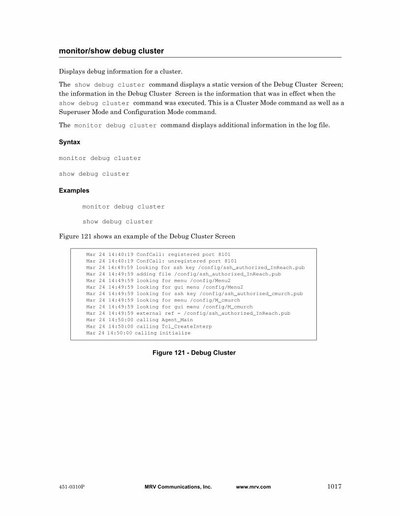
Displays debug information for a cluster.
The show debug cluster command displays a static version of the Debug Cluster Screen; the information in the Debug Cluster Screen is the information that was in effect when the show debug cluster command was executed. This is a Cluster Mode command as well as a Superuser Mode and Configuration Mode command.
The monitor debug cluster command displays additional information in the log file.
Syntax
monitor debug cluster
show debug cluster
Examples
monitor debug cluster
show debug cluster
Figure 121 shows an example of the Debug Cluster Screen
Figure 121 - Debug Cluster
monitor/show debug cluster
Mar 24 14:40:19 ConfCall: registered port 8101Mar 24 14:40:19 ConfCall: unregistered port 8101Mar 24 14:49:59 looking for ssh key /config/ssh_authorized_InReach.pubMar 24 14:49:59 adding file /config/ssh_authorized_InReach.pubMar 24 14:49:59 looking for menu /config/Menu2Mar 24 14:49:59 looking for gui menu /config/Menu2Mar 24 14:49:59 looking for ssh key /config/ssh_authorized_cmurch.pubMar 24 14:49:59 looking for menu /config/M_cmurchMar 24 14:49:59 looking for gui menu /config/M_cmurchMar 24 14:49:59 external ref = /config/ssh_authorized_InReach.pubMar 24 14:50:00 calling Agent_MainMar 24 14:50:00 calling Tcl_CreateInterpMar 24 14:50:00 calling initialize
451-0310P MRV Communications, Inc. www.mrv.com 1017
Removes member IP addresses from the cluster.
Syntax
no address <ip_address>|all
Where Means
Examples
no address 119.20.110.87
no address all
Displaying Information on No Address All
The cluster characteristics are displayed on the Cluster Characteristics Screen. An example of the Cluster Characteristics Screen appears in Figure 119 on page 1014.
Use the show cluster characteristics command to display the Cluster Characteristics Screen. Refer to “monitor/show cluster characteristics” on page 1014 for more information.
no address
ip_address The address of the node you want to remove from the cluster.
all Removes the addresses of all nodes from the cluster.
1018 MRV Communications, Inc. www.mrv.com 451-0310P

Configures the node’s cluster secret.
Syntax
secret <cluster_secret>
Where Means
Examples
secret abcdefg123456789
secret clusternodebosMA
Displaying Information on a Secret
The cluster secret is displayed as “Configured” on the Cluster Characteristics Screen. An example of the Cluster Characteristics Screen appears in Figure 119 on page 1014.
Use the show cluster characteristics command to display the Cluster Characteristics Screen. Refer to “monitor/show cluster characteristics” on page 1014 for more information.
secret
cluster_secret The unique cluster secret for the cluster. The secret must be a minimum of 16 characters, and a maximum of 32 characters. It can be made up of both letters and numbers, but it must start with a letter. This controls access to a specific cluster.
451-0310P MRV Communications, Inc. www.mrv.com 1019

Shares LX system attributes with other nodes in the cluster.
Syntax
share <attribute>
Where Means
Examples
share telnet daemon
share primary dns
share timezone
Displaying Information on Share
The shared attributes are displayed on the Cluster Characteristics Screen. An example of the Cluster Characteristics Screen appears in Figure 119 on page 1014.
Use the show cluster characteristics command to display the Cluster Characteristics Screen. Refer to “monitor/show cluster characteristics” on page 1014 for more information.
share
<attribute> System Attributes:
Primary Domain, Secondary Domain, Gateway, TFTP Timeout, TFTP Retries, NTP Server, SNMP Daemon, Finger Daemon, Timed Daemon, NTP Daemon, Telnet Daemon, SSH Daemon, Logging Size, Web_Server, Web Banner, Outlet Access, Timezone, Service Configuration, LDAP, RADIUS, SecurID, TACACS+, SNMP, TCP Pipe Retries, ThttpdPort
Subscriber Attributes:
All, Name, Port Access List, Outlet Access List, Outlet Group Access List, Change Password, Connect Escape Character
Port Async Attributes:
The complete port configuration is shared. Attributes are not individually sharable. The only attributes not shared on a port are Port Name, Outlet Name, Signal Notification, and SNMP Sensor Units/Alarm Severity.
1020 MRV Communications, Inc. www.mrv.com 451-0310P
Shares the authenticate image with the cluster members.
Syntax
share authenticate image
Examples
share authenticate image
Displaying Information on Share Authenticate Image
The shared authenticate image is displayed on the Cluster Characteristics Screen. An example of the Cluster Characteristics Screen appears in Figure 119 on page 1014.
Use the show cluster characteristics command to display the Cluster Characteristics Screen. Refer to “monitor/show cluster characteristics” on page 1014 for more information.
share authenticate image
451-0310P MRV Communications, Inc. www.mrv.com 1021
Shares interface(s) attributes with the cluster members.
Syntax
share interface all | <interface_number>
Where Means
Examples
share interface all
share interface 6
Displaying Information on Share Interface
The shared interfaces are displayed on the Cluster Characteristics Screen. An example of the Cluster Characteristics Screen appears in Figure 119 on page 1014.
Use the show cluster characteristics command to display the Cluster Characteristics Screen. Refer to “monitor/show cluster characteristics” on page 1014 for more information.
share interface
all Shares interface attributes with all cluster members.
interface_number The number of a specific interface with which you want to share attributes.
1022 MRV Communications, Inc. www.mrv.com 451-0310P
Shares the message with the cluster members.
Syntax
share message
Examples
share message
Displaying Information on Share Message
The shared message is displayed on the Cluster Characteristics Screen. An example of the Cluster Characteristics Screen appears in Figure 119 on page 1014.
Use the show cluster characteristics command to display the Cluster Characteristics Screen. Refer to “monitor/show cluster characteristics” on page 1014 for more information.
share message
451-0310P MRV Communications, Inc. www.mrv.com 1023
Shares subscriber(s) attributes with the cluster members.
Syntax
share subscriber all | <subscriber_name>
Where Means
Examples
share subscriber all
share subscriber billm
Displaying Information on Share Subscriber
The shared subscribers are displayed on the Cluster Characteristics Screen. An example of the Cluster Characteristics Screen appears in Figure 119 on page 1014.
Use the show cluster characteristics command to display the Cluster Characteristics Screen. Refer to “monitor/show cluster characteristics” on page 1014 for more information.
share subscriber
all Shares subscriber attributes with all cluster members.
subscriber_name A unique subscriber name with which you want to share attributes.
1024 MRV Communications, Inc. www.mrv.com 451-0310P

Shares the telnet client with the cluster members.
Syntax
share telnet client
Examples
share telnet client
Displaying Information on Share Telnet Client
The shared telnet client is displayed on the Cluster Characteristics Screen. An example of the Cluster Characteristics Screen appears in Figure 119 on page 1014.
Use the show cluster characteristics command to display the Cluster Characteristics Screen. Refer to “monitor/show cluster characteristics” on page 1014 for more information.
share telnet client
451-0310P MRV Communications, Inc. www.mrv.com 1025

You can execute each of the show commands in the Privilege Command Mode.
Refer to the following pages for a full description of each of the show commands.
• page 61 – show audit log command
• page 63 – show clock command
• page 64 – show command log command
• page 65 – show configuration command
• page 67 – show configuration log command
• page 73 – show debug all command
• page 74 – show debug flash command
• page 75 – show debug interface ppp command
• page 76 – show debug port async command
• page 79 – show debug snmp command
• page 81 – show debug system command
• page 83 – show device status command
• page 85 – show device summary command
• page 86 – show hdam alarm name characteristics command
• page 88 – show hdam alarm name status command
• page 93 – show hdam characteristics command
• page 96 – show hdam control name characteristics command
• page 97 – show hdam control name status command
• page 98 – show hdam mapping command
• page 100 – show hdam port/slot/point characteristics command
• page 103 – show hdam port/slot/point status command
• page 106 – show hdam status command
• page 108 – show interface bonding characteristics command
• page 110 – show interface bonding status command
• page 112 – show interface broadcast group characteristics command
show
1026 MRV Communications, Inc. www.mrv.com 451-0310P

• page 114 – show interface broadcast group summary command
• page 115 – show interface characteristics command
• page 121 – show interface port mapping command
• page 123 – show interface ppp characteristics command
• page 126 – show interface ppp status command
• page 128 – show interface rotary command
• page 129 – show interface status command
• page 131 – show interface summary command
• page 137 – show kernel log command
• page 138 – show ldap characteristics command
• page 140 – show ldap status command
• page 141 – show ldap summary command
• page 142 – show log command
• page 143 – show message command
• page 144 – show notification log command
• page 145 – show notification message command
• page 146 – show notification profile service command
• page 147 – show notification profile user command
• page 148 – show outlet command
• page 150 – show outlet group status command
• page 152 – show port apd command
• page 153 – show port async apd command
• page 155 – show port async characteristics command
• page 159 – show port async modem command
• page 161 – show port async status command
• page 166 – show port async summary command
• page 169 – show port characteristics command
• page 170 – show port ethernet characteristics command
• page 171 – show port ethernet status command
• page 173 – show port ethernet summary command
show (continued)
451-0310P MRV Communications, Inc. www.mrv.com 1027
• page 174 – show port modem command
• page 175 – show port status command
• page 176 – show radius characteristics command
• page 178 – show radius status command
• page 180 – show radius summary command
• page 182 – show route command
• page 183 – show securid characteristics command
• page 185 – show securid status command
• page 187 – show securid summary command
• page 188 – show service command
• page 189 – show session command
• page 191 – show snmp characteristics command
• page 192 – show snmp client command
• page 194 – show snmp v3 access command
• page 196 – show snmp v3 group command
• page 197 – show snmp v3 misc command
• page 198 – show snmp v3 user command
• page 200 – show snmp v3 view command
• page 202 – show subscriber command
• page 207 – show subscriber characteristics command
• page 208 – show subscriber status command
• page 209 – show subscriber summary command
• page 210 – show subscriber tcp command
• page 211 – show system characteristics command
• page 215 – show system ppciboot command
• page 218 – show system status command
• page 221 – show tacacs+ characteristics command
• page 224 – show tacacs+ status command
• page 226 – show tacacs+ summary command
• page 228 – show trigger-action action command
show (continued)
1028 MRV Communications, Inc. www.mrv.com 451-0310P

• page 229 – show trigger-action rule command
• page 234 – show trigger-action trigger command
• page 237 – show users command
• page 238 – show version command
show (continued)
451-0310P MRV Communications, Inc. www.mrv.com 1029
Unshares LX system attributes with other nodes in the cluster.
Syntax
unshare <attribute>
Where Means
Examples
unshare telnet daemon
unshare primary dns
unshare timezone
Displaying Information on Unshare
Unshared attributes are not displayed on the Cluster Characteristics Screen. An example of the Cluster Characteristics Screen appears in Figure 119 on page 1014.
Use the show cluster characteristics command to display the Cluster Characteristics Screen. Refer to “monitor/show cluster characteristics” on page 1014 for more information.
unshare
<attribute> System Attributes:
Primary Domain, Secondary Domain, Gateway, TFTP Timeout, TFTP Retries, NTP Server, SNMP Daemon, Finger Daemon, Timed Daemon, NTP Daemon, Telnet Daemon, SSH Daemon, Logging Size, Web_Server, Web Banner, Outlet Access, Timezone, Service Configuration, LDAP, RADIUS, SecurID, TACACS+, SNMP
Subscriber Attributes:
All, Name, Port Access List, Outlet Access List, Outlet Group Access List
Port Async Attributes:
The complete port configuration is shared. Attributes are not individually sharable. The only attributes not shared on a port are Port Name, Outlet Name, Signal Notification, and SNMP Sensor Units/Alarm Severity.
1030 MRV Communications, Inc. www.mrv.com 451-0310P

Removes an individual or all member interfaces from the cluster.
Syntax
unshare interface all | <interface_number>
Where Means
Examples
unshare interface all
unshare interface 8
Displaying Information on Unshare Interface
Only shared attributes and subscribers are displayed on the Cluster Characteristics Screen. Unshared attributes and subscribers are not displayed. An example of the Cluster Characteristics Screen appears in Figure 119 on page 1014.
Use the show cluster characteristics command to display the Cluster Characteristics Screen. Refer to “monitor/show cluster characteristics” on page 1014 for more information.
unshare interface
all Unshares all interfaces from the cluster.
interface_number The number of the interface to be unshared from the cluster.
451-0310P MRV Communications, Inc. www.mrv.com 1031
Removes all local interfaces or a specific interface from the cluster.
Syntax
unshare local interface all | <interface_number>
Where Means
Usage Guidelines
To unshare the interface for all or a specific LX node. This LX uses its own setting for this field and not that value of the cluster.
Examples
unshare local interface all
unshare local interface 3
Displaying Information on Unshare Local Subscriber
The local subscribers are displayed on the Cluster Characteristics Screen. An example of the Cluster Characteristics Screen appears in Figure 119 on page 1014.
Use the show cluster characteristics command to display the Cluster Characteristics Screen. Refer to “monitor/show cluster characteristics” on page 1014 for more information.
unshare local interface
all Unshares all interfaces on the node.
interface_number The number of the local interface to be unshared.
1032 MRV Communications, Inc. www.mrv.com 451-0310P
Removes all local subscribers or a specific subscriber from the cluster.
Syntax
unshare local subscriber all | <subscriber_name>
Where Means
Usage Guidelines
To unshare the attribute for all or a specific LX node. This LX uses its own setting for this field and not that value of the cluster.
Examples
unshare local subscriber all
unshare local subscriber name FieldOffice3
Displaying Information on Unshare Local Subscriber
The local subscribers are displayed on the Cluster Characteristics Screen. An example of the Cluster Characteristics Screen appears in Figure 119 on page 1014.
Use the show cluster characteristics command to display the Cluster Characteristics Screen. Refer to “monitor/show cluster characteristics” on page 1014 for more information.
unshare local subscriber
all Unshares all subscribers on the node.
subscriber_name The name of the local subscriber to be unshared.
451-0310P MRV Communications, Inc. www.mrv.com 1033

Removes an individual or all member subscribers from the cluster.
Syntax
unshare subscriber all | <subscriber_name>
Where Means
Examples
unshare subscriber all
unshare subscriber name FieldOffice8
Displaying Information on Unshare Subscriber
Only shared attributes and subscribers are displayed on the Cluster Characteristics Screen. Unshared attributes and subscribers are not displayed. An example of the Cluster Characteristics Screen appears in Figure 119 on page 1014.
Use the show cluster characteristics command to display the Cluster Characteristics Screen. Refer to “monitor/show cluster characteristics” on page 1014 for more information.
unshare subscriber
all Unshares all subscribers from the cluster.
subscriber_name The name of the subscriber to be unshared from the cluster.
1034 MRV Communications, Inc. www.mrv.com 451-0310P
Chapter 31
High Density Alarm Manager (HDAM)Commands
The High Density Alarm Manager (HDAM) commands are executed in the superuser InReach:0>> mode and the Config:0>> mode.
The format of these command prompts is as follows:
InReach:<session_number> >>
Config:<session_number> >>
To enter the Config:0>> command mode, enter the config command in the InReach:0>> command mode, or type config, followed by the HDAM command of your choice in the superuser InReach:0>> mode.
IMPORTANTThe IR-7104 HDAM is compatible only with the LX-Series. It is no longer compatible with In-Reach legacy products.
451-0310P MRV Communications, Inc. www.mrv.com 1035

When the end command is issued in the Config command mode, it returns the user to the Superuser command mode.
Syntax
end
Usage Guidelines
The end command can be issued in all of the LX command modes except for User and Superuser. Executing the end command always returns the user to the Superuser command mode.
Example
end
end
1036 MRV Communications, Inc. www.mrv.com 451-0310P
Returns the user to the previous command mode.
Syntax
exit
Usage Guidelines
The exit command can be issued in all of the LX command modes. However, the effect of the exit command varies, depending on the command mode from which it is issued. Issuing the exit command in most command modes returns the user to the previous command mode.
Issuing the exit command in the User command mode exits the LX CLI and closes the connection to the LX unit.
Example
exit
exit
451-0310P MRV Communications, Inc. www.mrv.com 1037
Resets the name of a single named alarm input to its default name.
Syntax
hdam alarm <alarm_name> default name
Where Means
Usage Guidelines
The default name for an alarm input is canonically derived from the port number, slot number
and point number. For example, the default name for the 31st alarm input on the 2nd slot of the HDAM being managed by port 5 is 5_2_31.
Use the default name command when you want to return an alarm point name to its default numeric value.
Examples
hdam alarm DoorAlarm default name
hdam alarm default name
alarm_name The name of the alarm input you want to reset to the default name.
1038 MRV Communications, Inc. www.mrv.com 451-0310P

Renames the given alarm.
Syntax
hdam alarm <alarm_name_1> name <alarm_name_2>
Where Means
Usage Guidelines
The alarm name can be a maximum of 31 characters long. Use the default name command when you want to return an alarm point name to its default numeric value.
Examples
hdam alarm 5_2_31 name DoorAlarm
hdam alarm DoorAlarm name WindowAlarm
Displaying Information on HDAM Alarm Name
The Alarm Name is displayed on the HDAM Alarm Name Characteristics Screen. An example of the HDAM Alarm Name Characteristics Screen appears in Figure 21 on page 86.
Use the show hdam alarm characteristics command to display the HDAM Alarm Name Characteristics Screen. Refer to “monitor/show hdam alarm name characteristics” on page 86 for more information.
hdam alarm name
alarm_name_1 The name of the alarm input you want to rename.
alarm_name_2 The new alarm name you want to assign the alarm input. This command fails if the name <alarm_name_2> is already in use. The name must start with a letter, and the remainder of the name can contain only letters and/or numbers and/or underscores.
451-0310P MRV Communications, Inc. www.mrv.com 1039
Enables the audible alarm for a single named alarm.
Syntax
hdam alarm <alarm_name> audible enable
Where Means
Usage Guidelines
To disable this feature, enter hdam alarm <alarm_name> no audible.
Examples
hdam alarm 5_2_31 audible enable
hdam alarm WindowAlarm no audible
Displaying Information on HDAM Alarm Name Audible
The Alarm Name Audible is displayed on the HDAM Alarm Name Characteristics Screen. An example of the HDAM Alarm Name Characteristics Screen appears in Figure 21 on page 86.
Use the show hdam alarm <alarm_name> characteristics command to display the HDAM Alarm Name Characteristics Screen. Refer to “monitor/show hdam alarm name characteristics” on page 86 for more information.
hdam alarm name audible enable
alarm_name The name of the alarm to which you want to enable the audible alarm.
1040 MRV Communications, Inc. www.mrv.com 451-0310P

Configures the debounce interval for a single named alarm. The debounce is the grace period after which the alarm input is first faulted and consecutive faults will not be alarmed/trapped.
Syntax
hdam alarm <alarm_name> debounce <time>
Where Means
Examples
hdam alarm 5_2_31 debounce 30
hdam alarm WindowAlarm debounce 1800
Displaying Information on HDAM Alarm Name Debounce
The Alarm Name Debounce is displayed on the HDAM Alarm Name Characteristics Screen. An example of the HDAM Alarm Name Characteristics Screen appears in Figure 21 on page 86.
Use the show hdam alarm <alarm_name> characteristics command to display the HDAM Alarm Name Characteristics Screen. Refer to “monitor/show hdam alarm name characteristics” on page 86 for more information.
hdam alarm name debounce
alarm_name The name of the alarm to which you want to set a debounce interval.
time Specifies the number of seconds for which the alarm must be in the fault state before it is considered faulted. Allowable values are 0 - 1800 seconds. The default value is 0.
451-0310P MRV Communications, Inc. www.mrv.com 1041

Configures the default description for a single named alarm.
Syntax
hdam alarm <alarm_name> default description
Where Means
Examples
hdam alarm 5_2_31 default description
hdam alarm WindowAlarm default description
Displaying Information on Alarm Name Default Description
The Alarm Name Default Description is displayed on the HDAM Alarm Name Characteristics Screen. An example of the HDAM Alarm Name Characteristics Screen appears in Figure 21 on page 86.
Use the show hdam alarm name characteristics command to display the HDAM Alarm Name Characteristics Screen. Refer to “monitor/show hdam alarm name characteristics” on page 86 for more information.
hdam alarm name default description
alarm_name The name of the alarm to which you want to add a default description.
1042 MRV Communications, Inc. www.mrv.com 451-0310P
Resets all configurable values to defaults for a single named alarm.
Syntax
hdam alarm <alarm_name> default point
Where Means
Usage Guidelines
Defaults reset include the Name, Trap Severity (to Minor), Trap Setting (to Enable), Description (removes any description), Audible (Disabled), Debounce (reset to 0), and Fault State (reset to Normal).
Examples
hdam alarm 5_2_31 default point
hdam alarm 3_1_22 default point
hdam alarm name default point
alarm_name The name of the alarm you want to default.
451-0310P MRV Communications, Inc. www.mrv.com 1043
Configures the description string for a single named alarm.
Syntax
hdam alarm <alarm_name> description <string>
Where Means
Examples
hdam alarm 5_2_31 description secondfloorlab
hdam alarm WindowAlarm description halldoor
hdam alarm 8_1_1 description third floor office by computer room
Displaying Information on Alarm Name Description
The Alarm Name Description is displayed on the HDAM Alarm Name Characteristics Screen. An example of the HDAM Alarm Name Characteristics Screen appears in Figure 21 on page 86.
Use the show hdam alarm name characteristics command to display the HDAM Alarm Name Characteristics Screen. Refer to “monitor/show hdam alarm name characteristics” on page 86 for more information.
hdam alarm name description
alarm_name The name of the alarm to which you want to add a description.
string The description of the alarm. This string can be up to 63 characters long.
1044 MRV Communications, Inc. www.mrv.com 451-0310P
Configures the fault state for a single named alarm.
Syntax
hdam alarm <alarm_name> fault state [open|closed]
Where Means
Usage Guidelines
Use this command to configure the fault state of a single alarm to open or closed. When the alarm is in the state configured by this command, it is in the faulted state. When the alarm transitions into the faulted state (after the debounce interval), an SNMP trap is sent (if configured to do so) and any associated trigger-action triggers are executed.
Examples
hdam alarm 5_2_31 fault state open
hdam alarm WindowAlarm fault state closed
Displaying Information on HDAM Alarm Name Fault State
The Alarm Name Fault State is displayed on the HDAM Alarm Name Characteristics Screen. An example of the HDAM Alarm Name Characteristics Screen appears in Figure 21 on page 86.
Use the show hdam alarm name characteristics command to display the HDAM Alarm Name Characteristics Screen. Refer to “monitor/show hdam alarm name characteristics” on page 86 for more information.
hdam alarm name fault state
alarm_name The name of the alarm input on which you want change the fault state.
451-0310P MRV Communications, Inc. www.mrv.com 1045

Configures a single named alarm to send SNMP traps.
Syntax
hdam alarm <alarm_name> trap enable
Where Means
Usage Guidelines
Traps are enabled by default. Use this command to configure an alarm input so that SNMP traps are sent when the alarm enters or leaves the faulted state (after the debounce interval). To disable this feature, enter hdam alarm <alarm_name> no trap.
Examples
hdam alarm 5_2_31 trap enable
hdam alarm WindowAlarm no trap
Displaying Information on HDAM Alarm Name Trap Enable
The Alarm Name Trap Setting is displayed on the HDAM Alarm Name Characteristics Screen. An example of the HDAM Alarm Name Characteristics Screen appears in Figure 21 on page 86.
Use the show hdam alarm name characteristics command to display the HDAM Alarm Name Characteristics Screen. Refer to “monitor/show hdam alarm name characteristics” on page 86 for more information.
hdam alarm name trap enable
alarm_name The name of the alarm input about which you want to issue traps.
1046 MRV Communications, Inc. www.mrv.com 451-0310P

Configures the trap severity of a single named alarm.
Syntax
hdam alarm <alarm_name> trap severity <severity_level>
Where Means
Usage Guidelines
This value is sent along with any Alarm, Fault, or Event traps.
Examples
hdam alarm 5_2_31 trap severity critical
hdam alarm 5_2_31 trap severity information
hdam alarm WindowAlarm trap severity major
hdam alarm 5_2_31 trap severity minor
hdam alarm 5_2_31 trap severity warning
Displaying Information on HDAM Alarm Name Trap Severity
The Alarm Name Trap Severity is displayed on the HDAM Port/Slot/Point Characteristics Alarm Card Screen. An example of the HDAM Port/Slot/Point Characteristics Alarm Card Screen appears in Figure 30 on page 101.
Use the show hdam <port_number> slot <slot_list> point <point_list> characteristics command to display the HDAM Port/Slot/Point Characteristics Alarm Card Screen. Refer to “monitor/show hdam port/slot/point characteristics” on page 100 for more information.
hdam alarm name trap severity
alarm_name The name of the alarm input on which you want to set trap severity.
severity_level The severity level of the trap. The options are Critical, Information, Major, Minor, and Warning.
451-0310P MRV Communications, Inc. www.mrv.com 1047
Configures the audible alarm for one or more alarms.
Syntax
hdam alarm port <port_number> slot [<slot_list>|all] point [<point_list>|all]
audible enable
Where Means
Usage Guidelines
To disable this feature, enter hdam alarm port <port_number> slot <slot_list> point <point_list> no audible.
Examples
hdam alarm port 2 slot 2 point 2 audible enable
hdam alarm port 2 slot 1,2 point 1,2,3,4 audible enable
hdam alarm port 2 slot 2-4 point 6-18 audible enable
hdam alarm port 2 slot all point all no audible
hdam alarm port 2 slot 1-3 point 1,2,6-18 no audible
Displaying Information on HDAM Port/Slot/Point Audible Alarm
The Alarm Port/Slot/Point Audible Alarm is displayed on the HDAM Port/Slot/Point Characteristics Alarm Card Screen. An example of the HDAM Port/Slot/Point Characteristics Alarm Card Screen appears in Figure 30 on page 101.
Use the show hdam <port_number> slot <slot_list> point <point_list> characteristics command to display the HDAM Port/Slot/Point Characteristics Alarm Card Screen. Refer to “monitor/show hdam port/slot/point characteristics” on page 100 for more information.
hdam alarm port/slot/point audible enable
port_number The number of the port to which the HDAM is connected.
slot_list The list of the slots (or all) on which you want to enable the audible alarm.
point_list The list of the points on which you want to enable the audible alarm.
1048 MRV Communications, Inc. www.mrv.com 451-0310P

Configures the debounce interval for one or more alarms.
Syntax
hdam alarm port <port_number> slot [<slot_list>|all] point [<point_list>|all]
debounce <time>
Where Means
Examples
hdam alarm port 2 slot 1,2 point 1,2,3,4 debounce 30
hdam alarm port 2 slot 2-4 point 6-18 debounce 20
hdam alarm port 2 slot all point all debounce 90
hdam alarm port 2 slot 1-3 point 1,2,6-18 debounce 45
Displaying Information on HDAM Alarm Port/Slot/Point Debounce Interval
The Alarm Port/Slot/Point Debounce Interval is displayed on the HDAM Port/Slot/Point Characteristics Alarm Card Screen. An example of the HDAM Port/Slot/Point Characteristics Alarm Card Screen appears in Figure 30 on page 101.
Use the show hdam <port_number> slot <slot_list> point <point_list> characteristics command to display the HDAM Port/Slot/Point Characteristics Alarm Card Screen. Refer to “monitor/show hdam port/slot/point characteristics” on page 100 for more information.
hdam alarm port/slot/point debounce
port_number The number of the port to which the HDAM is connected.
slot_list The list of the slots on which you want to set the debounce interval.
point_list The list of the points on which you want to set the debounce interval.
time Specifies the number of seconds for which the alarm must be in the fault state before it is considered faulted. Allowable values are 0 - 1800 seconds. The default value is 0.
451-0310P MRV Communications, Inc. www.mrv.com 1049
Configures a default description for a one or more alarms.
Syntax
hdam alarm port <port_number> slot [<slot_list>|all] point [<point_list>|all]
default description
Where Means
Usage Guidelines
This command allows you to specify ranges of slots and ports (respectively). You can use all, a comma-separated list of numbers (e.g. 1,3,4), a range of numbers (e.g. 2-28), or a combination thereof (e.g. 1,2,5-18). Using lists allows you to execute commands on multiple points. If any of the values specified are beyond the configurable range or are invalid, the command is aborted and an appropriate message is displayed.
Examples
hdam alarm port 2 slot 1,2 point 1,2,3,4 default description
hdam alarm port 2 slot 2-4 point 6-18 default description
hdam alarm port 2 slot all point all default description
hdam alarm port 2 slot 1-3 point 1,2,6-18 default description
Displaying Information on HDAM Alarm Default Description
The Alarm Default Description is displayed on the HDAM Port/Slot/Point Characteristics Alarm Card Screen. An example of the HDAM Port/Slot/Point Characteristics Alarm Card Screen appears in Figure 30 on page 101.
Use the show hdam <port_number> slot <slot_list> point <point_list> characteristics command to display the HDAM Port/Slot/Point Characteristics Alarm Card Screen. Refer to “monitor/show hdam port/slot/point characteristics” on page 100 for more information.
hdam alarm port/slot/point default description
port_number The number of the port to which the HDAM is connected.
slot_list The list of the slots whose points you want to configure a description for.
point_list The list of the points for which you want to configure a description.
1050 MRV Communications, Inc. www.mrv.com 451-0310P

Resets the name of one or more alarm inputs to their default names.
Syntax
hdam alarm port <port_number> slot [<slot_list>|all] point [<point_list>|all]
default name
Where Means
Usage Guidelines
This command allows you to specify ranges of slots and ports (respectively). You can use all, a comma-separated list of numbers (e.g. 1,3,4), a range of numbers (e.g. 2-28), or a combination thereof (e.g. 1,2,5-18). Using lists allows you to execute commands on multiple points. If any of the values specified are beyond the configurable range or are invalid, the command is aborted and an appropriate message is displayed. Use the default name command when you want to return an alarm point name to its default numeric value.
Examples
hdam alarm port 2 slot 1,2 point 1,2,3,4 default name
hdam alarm port 2 slot 1-3 point 6-18 default name
hdam alarm port 2 slot all point all default name
hdam alarm port 2 slot 1-3 point 1,2,6-18 default name
Displaying Information on HDAM Alarm Port/Slot/Point Default Name
The Alarm Port/Slot/Point Default Name is displayed on the HDAM Port/Slot/Point Characteristics Alarm Card Screen. An example of the HDAM Port/Slot/Point Characteristics Alarm Card Screen appears in Figure 30 on page 101.
Use the show hdam <port_number> slot <slot_list> point <point_list> characteristics command to display the HDAM Port/Slot/Point Characteristics Alarm Card Screen. Refer to “monitor/show hdam port/slot/point characteristics” on page 100 for more information.
hdam alarm port/slot/point default name
port_number The number of the port to which the HDAM is connected.
slot_list The list of the slots whose points you want to reset to the default name.
point_list The list of the points you want to reset to the default name.
451-0310P MRV Communications, Inc. www.mrv.com 1051

Resets one or more alarms to their default values.
Syntax
hdam alarm port <port_number> slot [<slot_list>|all] point [<point_list>|all]
default point
Where Means
Usage Guidelines
This command allows you to specify ranges of slots and ports (respectively). You can use all, a comma-separated list of numbers (e.g. 1,3,4), a range of numbers (e.g. 2-28), or a combination thereof (e.g. 1,2,5-18). Using lists allows you to execute commands on multiple points. If any of the values specified are beyond the configurable range or are invalid, the command is aborted and an appropriate message is displayed.
Examples
hdam alarm port 2 slot 1,2 point 1,2,3,4 default point
hdam alarm port 2 slot 2-4 point 6-18 default point
hdam alarm port 2 slot all point all default point
hdam alarm port 2 slot 1-3 point 1,2,6-18 default point
Displaying Information on HDAM Alarm Port/Slot/Point Default Point
The Alarm Port/Slot/Point Default Point is displayed on the HDAM Port/Slot/Point Characteristics Alarm Card Screen. An example of the HDAM Port/Slot/Point Characteristics Alarm Card Screen appears in Figure 30 on page 101.
Use the show hdam <port_number> slot <slot_list> point <point_list> characteristics command to display the HDAM Port/Slot/Point Characteristics Alarm Card Screen. Refer to “monitor/show hdam port/slot/point characteristics” on page 100 for more information.
hdam alarm port/slot/point default point
port_number The number of the port to which the HDAM is connected.
slot_list The list of the slots whose points you want to default.
point_list The list of the points you want to default.
1052 MRV Communications, Inc. www.mrv.com 451-0310P
Configures a description string for a one or more alarms.
Syntax
hdam alarm port <port_number> slot [<slot_list>|all] point [<point_list>|all]
description <string>
Where Means
Usage Guidelines
This command allows you to specify ranges of slots and ports (respectively). You can use all, a comma-separated list of numbers (e.g. 1,3,4), a range of numbers (e.g. 2-28), or a combination thereof (e.g. 1,2,5-18). Using lists allows you to execute commands on multiple points. If any of the values specified are beyond the configurable range or are invalid, the command is aborted and an appropriate message is displayed.
Examples
hdam alarm port 2 slot 1,2 point 1,2,3,4 description lab1
hdam alarm port 2 slot 2-4 point 6-18 description lab2
hdam alarm port 2 slot all point all description library on 2nd floor
hdam alarm port 2 slot 1-3 point 1,2,6-18 description lab6
Displaying Information on HDAM Alarm Description String
The Alarm Description String is displayed on the HDAM Port/Slot/Point Characteristics Alarm Card Screen. An example of the HDAM Port/Slot/Point Characteristics Alarm Card Screen appears in Figure 30 on page 101.
Use the show hdam <port_number> slot <slot_list> point <point_list> characteristics command to display the HDAM Port/Slot/Point Characteristics Alarm Card Screen. Refer to “monitor/show hdam port/slot/point characteristics” on page 100 for more information.
hdam alarm port/slot/point description
port_number The number of the port to which the HDAM is connected.
slot_list The list of the slots whose points you want to configure a description for.
point_list The list of the points for which you want to configure a description.
string The description of the alarm. This string can be up to 63 characters long.
451-0310P MRV Communications, Inc. www.mrv.com 1053
Configures the fault state for one or more alarms.
Syntax
hdam alarm port <port_number> slot [<slot_list>|all] point [<point_list>|all]
fault state [open|closed]
Where Means
Usage Guidelines
Use this command to configure the fault state of one or more alarms to open or closed. When the alarm is in the state configured by this command, it is in the faulted state. When the alarm transitions into the faulted state (after the debounce interval), an SNMP trap is sent (if configured to do so) and any associated trigger-action triggers are executed.
Examples
hdam alarm port 2 slot 1,2 point 1,2,3,4 fault state open
hdam alarm port 2 slot 2-4 point 6-18 fault state closed
hdam alarm port 2 slot all point all fault state open
hdam alarm port 2 slot 1-3 point 1,2,6-18 fault state closed
Displaying Information on HDAM Alarm Port/Slot/Point Fault State
The Alarm Port/Slot/Point Fault State is displayed on the HDAM Port/Slot/Point Characteristics Alarm Card Screen. An example of the HDAM Port/Slot/Point Characteristics Alarm Card Screen appears in Figure 30 on page 101.
Use the show hdam <port_number> slot <slot_list> point <point_list> characteristics command to display the HDAM Port/Slot/Point Characteristics Alarm Card Screen. Refer to “monitor/show hdam port/slot/point characteristics” on page 100 for more information.
hdam alarm port/slot/point fault state
port_number The number of the port to which the HDAM is configured.
slot_list The list of the slots on whose points you want to change the fault state.
point_list The list of the points on which you want to change the fault state.
1054 MRV Communications, Inc. www.mrv.com 451-0310P
Renames a given alarm.
Syntax
hdam alarm port <port_number> slot <slot_number> point <point_number> name
<new_name>
Where Means
Usage Guidelines
You cannot list multiple slots or points, because point names must be unique.
Examples
hdam alarm port 2 slot 1 point 1 name lab1
hdam alarm port 2 slot 4 point 18 name lab2
hdam alarm port 2 slot 1 point 6 name lab6
Displaying Information on HDAM Alarm Port/Slot/Point Name
The Alarm Port/Slot/Point Name is displayed on the HDAM Port/Slot/Point Characteristics Alarm Card Screen. An example of the HDAM Port/Slot/Point Characteristics Alarm Card Screen appears in Figure 30 on page 101.
Use the show hdam <port_number> slot <slot_list> point <point_list> characteristics command to display the HDAM Port/Slot/Point Characteristics Alarm Card Screen. Refer to “monitor/show hdam port/slot/point characteristics” on page 100 for more information.
hdam alarm port/slot/point name
port_number The number of the port to which the HDAM is connected.
slot_number The number of the slot on whose point you want to give the new name.
point_number The number of the point you want to give the new name.
new_name The new name of the alarm. The name can be a maximum of 31 characters long. The name must start with a letter, and the remainder of the name can contain only letters and/or numbers and/or underscores.
451-0310P MRV Communications, Inc. www.mrv.com 1055

Configures one or more alarms to send SNMP traps.
Syntax
hdam alarm port <port_number> slot [<slot_list>|all] point [<point_list>|all]
trap enable
Where Means
Usage Guidelines
This command allows you to specify ranges of slots and ports (respectively). You can use all, a comma-separated list of numbers (e.g. 1,3,4), a range of numbers (e.g. 2-28), or a combination thereof (e.g. 1,2,5-18). Using lists allows you to execute commands on multiple points. If any of the values specified are beyond the configurable range or are invalid, the command is aborted and an appropriate message is displayed.
To disable this feature, enter hdam alarm port <port_number> slot <slot_list> point <point_list> no trap.
Examples
hdam alarm port 2 slot 1,2 point 1,2,3,4 trap enable
hdam alarm port 2 slot 2-4 point 6-18 trap enable
hdam alarm port 2 slot all point all trap enable
hdam alarm port 2 slot 1-3 point 1,2,6-18 trap enable
hdam alarm port 2 slot 1-3 point 6-18 no trap
Displaying Information on HDAM Alarm Port/Slot/Point Trap Setting
The Alarm Port/Slot/Point Trap Setting is displayed on the HDAM Port/Slot/Point Characteristics Alarm Card Screen. An example of the HDAM Port/Slot/Point Characteristics Alarm Card Screen appears in Figure 30 on page 101.
Use the show hdam <port_number> slot <slot_list> point <point_list> characteristics command to display the HDAM Port/Slot/Point Characteristics Alarm Card Screen. Refer to “monitor/show hdam port/slot/point characteristics” on page 100 for more information.
hdam alarm port/slot/point trap enable
port_number The number of the port to which the HDAM is connected.
slot_list The list of the slots whose points about which you want to send SNMP traps.
point_list The list of the points about which you want to send SNMP traps.
1056 MRV Communications, Inc. www.mrv.com 451-0310P
Configures the trap severity for one or more alarms.
Syntax
hdam alarm port <port_number> slot [<slot_list>|all] point [<point_list>|all]
trap severity <severity_level>
Where Means
Usage Guidelines
This command allows you to specify ranges of slots and ports (respectively). You can use all, a comma-separated list of numbers (e.g. 1,3,4), a range of numbers (e.g. 2-28), or a combination thereof (e.g. 1,2,5-18). Using lists allows you to execute commands on multiple points. If any of the values specified are beyond the configurable range or are invalid, the command is aborted and an appropriate message is displayed.
Examples
hdam alarm port 2 slot 1,2 point 1,2,3,4 trap severity critical
hdam alarm port 2 slot 2-4 point 6-18 trap severity information
hdam alarm port 2 slot all point all trap severity major
hdam alarm port 2 slot 1-3 point 1,2,6-18 trap severity minor
hdam alarm port 2 slot 1-3 point 6-18 trap severity warning
Displaying Information on HDAM Alarm Port/Slot/Point Trap Severity
The Alarm Port/Slot/Point Trap Severity is displayed on the HDAM Port/Slot/Point Characteristics Alarm Card Screen. An example of the HDAM Port/Slot/Point Characteristics Alarm Card Screen appears in Figure 30 on page 101.
Use the show hdam <port_number> slot <slot_list> point <point_list> characteristics command to display the HDAM Port/Slot/Point Characteristics Alarm Card Screen. Refer to “monitor/show hdam port/slot/point characteristics” on page 100 for more information.
hdam alarm port/slot/point trap severity
port_number The number of the port to which the HDAM is connected.
slot_list The list of the slots whose points you want to set trap severity on.
point_list The list of the points at which you want to set trap severity.
severity_level The severity level of the trap. The options are Critical, Information, Major, Minor, and Warning.
451-0310P MRV Communications, Inc. www.mrv.com 1057
Resets the name of a single named analog input to its default name.
Syntax
hdam analog <analog_name> default name
Where Means
Usage Guidelines
The default name for an analog input is canonically derived from the port number, slot number
and point number. For example, the default name for the 8th analog input on the 2nd slot of the HDAM being managed by port 5 is 5_2_8.
Use the default name command when you want to return an analog point name to its default value.
Examples
hdam analog DoorAlarm default name
hdam analog default name
analog_name The name of the analog input you want to reset to the default name.
1058 MRV Communications, Inc. www.mrv.com 451-0310P

Renames the given analog.
Syntax
hdam analog <analog_name_1> name <analog_name_2>
Where Means
Usage Guidelines
The analog name can be a maximum of 31 characters long. Use the default name command when you want to return an analog point name to its default value.
Examples
hdam analog 5_2_31 name DoorAlarm
hdam analog DoorAlarm name WindowAlarm
Displaying Information on HDAM Analog Name
The Analog Name is displayed on the HDAM Analog Name Characteristics Screen. An example of the HDAM Analog Name Characteristics Screen appears in Figure 23 on page 89.
Use the show hdam analog characteristics command to display the HDAM Analog Name Characteristics Screen. Refer to “monitor/show hdam analog name characteristics” on page 89 for more information.
hdam analog name
analog_name_1 The name of the analog input you want to rename.
analog_name_2 The new analog name you want to assign the analog input. This command fails if the name <analog_name_2> is already in use. The name must start with a letter, and the remainder of the name can contain only letters and/or numbers and/or underscores.
451-0310P MRV Communications, Inc. www.mrv.com 1059

Configures the calibration values and a native unit identifier for a single named analog input.
Syntax
hdam analog <analog_point_name> calibrate minimum <minimum_value> maximum
<maximum_value> units <unit_name_string> [margin <margin_value>]
Where Means
Examples
hdam analog 5_2_8 calibrate minimum 32 maximum 120 units fahrnht margin 1.000
hdam analog 5_2_8 calibrate minimum 10 maximum 30 units psi
Displaying Information on Analog Unit Calibration
The Analog Name Calibration is displayed on the HDAM Analog Name Characteristics Screen. An example of the HDAM Analog Name Characteristics Screen appears in Figure 23 on page 89.
Use the show hdam analog characteristics command to display the HDAM Analog Name Characteristics Screen. Refer to “monitor/show hdam analog name characteristics” on page 89 for more information.
hdam analog name calibrate
analog_name The name of the analog on which you want to calibrate values.
minimum_value The minimum calibration setting. The range is -9999.9999 to 9999.9999. Refer to your analog device manual for the minimum/maximum values for 4-20 milliamps.
maximum_value The maximum calibration setting. The range is -9999.9999 to 9999.9999. Refer to your analog device manual for the minimum/maximum values for 4-20 milliamps.
unit_name_string The name of the unit. This can be from 1 to 7 characters long, and consists of the type of units the sensors are to report in (celsius/fahrenheit).
margin_value The optional margin value. The margin is used to adjust the reading in software so the actual output of the sensor can be calibrated to an external baseline. This value is used to adjust a sensor reading before being displayed and/or used in analog trigger-action rules. The range is -9999.9999 to 9999.9999.
1060 MRV Communications, Inc. www.mrv.com 451-0310P

Resets all configurable values to defaults for a single named analog point.
Syntax
hdam analog <analog_name> default point
Where Means
Usage Guidelines
Defaults reset the Name, Description (removes any description), State (Disabled), Minimum (0), Maximum (0), Margin (0), Calibration values, and Native Units (removes identifiers).
Examples
hdam analog 5_2_8 default point
hdam analog 3_1_8 default point
hdam analog name default point
analog_name The name of the analog you want to default.
451-0310P MRV Communications, Inc. www.mrv.com 1061

Configures the description string for a single named analog point.
Syntax
hdam analog <analog_name> description <string>
Where Means
Examples
hdam analog 5_2_8 description secondfloorlab
hdam analog WindowAlarm description halldoor
hdam analog 8_1_1 description third floor office by computer room
Displaying Information on Analog Name Description
The Analog Name Description is displayed on the HDAM Analog Name Characteristics Screen. An example of the HDAM Analog Name Characteristics Screen appears in Figure 23 on page 89.
Use the show hdam analog characteristics command to display the HDAM Analog Name Characteristics Screen. Refer to “monitor/show hdam analog name characteristics” on page 89 for more information.
hdam analog name description
analog_name The name of the analog to which you want to add a description.
string The description of the analog. This string can be up to 63 characters long.
1062 MRV Communications, Inc. www.mrv.com 451-0310P
Configures the calibration values and a native unit identifier for multiple named analog inputs.
Syntax
hdam analog port <port_number> slot [<slot_list>|all] point
[<point_list>|all]calibrate minimum <minimum_value> maximum <maximum_value>
units <unit_name_string> [margin <margin_value>]
Where Means
Examples
hdam analog port 2 slot 1,2 point 1,2,3,4 calibrate minimum 4 maximum 12 units fahrnht margin 0.500
hdam analog port 2 slot 1-3 point 6-8 calibrate minimum 5 maximum 140 units tempF
Displaying Information on Analog Unit Calibration
The Analog Unit Calibration is displayed on the HDAM Analog Name Characteristics Screen. An example of the HDAM Analog Name Characteristics Screen appears in Figure 23 on page 89.
hdam analog port/slot/point calibrate
port_number The number of the port to which the HDAM is connected.
slot_list The list of the slots whose points you want to calibrate.
point_list The list of the points you want to calibrate.
minimum_value The minimum calibration setting. The range is -9999.9999 to 9999.9999. Refer to your analog device manual for the minimum/maximum values for 4-20 milliamps.
maximum_value The maximum calibration setting. The range is -9999.9999 to 9999.9999. Refer to your analog device manual for the minimum/maximum values for 4-20 milliamps.
unit_name_string The name of the unit. This can be from 1 to 7 characters long, and consists of the type of units the sensors are to report in (celsius/fahrenheit).
margin_value The optional margin value. The margin is used to adjust the reading in software so the actual output of the sensor can be calibrated to an external baseline. This value is used to adjust a sensor reading before being displayed and/or used in analog trigger-action rules. The range is -9999.9999 to 9999.9999.
451-0310P MRV Communications, Inc. www.mrv.com 1063

Use the show hdam analog characteristics command to display the HDAM Analog Name Characteristics Screen. Refer to “monitor/show hdam analog name characteristics” on page 89 for more information.
hdam analog port/slot/point calibrate (continued)
1064 MRV Communications, Inc. www.mrv.com 451-0310P

Resets the name of one or more analog inputs to their default names.
Syntax
hdam analog port <port_number> slot [<slot_list>|all] point [<point_list>|all]
default name
Where Means
Usage Guidelines
This command allows you to specify ranges of slots and ports (respectively). You can use all, a comma-separated list of numbers (e.g. 1,3,4), a range of numbers (e.g. 2-28), or a combination thereof (e.g. 1,2,5-18). Using lists allows you to execute commands on multiple points. If any of the values specified are beyond the configurable range or are invalid, the command is aborted and an appropriate message is displayed. Use the default name command when you want to return an analog point name to its default value.
Examples
hdam analog port 2 slot 1,2 point 1,2,3,4 default name
hdam analog port 2 slot 1-3 point 6-8 default name
hdam analog port 2 slot all point all default name
hdam analog port 2 slot 1-3 point 1,2,6-8 default name
Displaying Information on HDAM Analog Port/Slot/Point Default Name
The Analog Name is displayed on the HDAM Analog Name Characteristics Screen. An example of the HDAM Analog Name Characteristics Screen appears in Figure 23 on page 89.
Use the show hdam analog characteristics command to display the HDAM Analog Name Characteristics Screen. Refer to “monitor/show hdam analog name characteristics” on page 89 for more information.
hdam analog port/slot/point default name
port_number The number of the port to which the HDAM is connected.
slot_list The list of the slots whose points you want to reset to their respective default names.
point_list The list of the points you want to reset to their respective default names.
451-0310P MRV Communications, Inc. www.mrv.com 1065

Resets one or more analogs to their default values.
Syntax
hdam analog port <port_number> slot [<slot_list>|all] point [<point_list>|all]
default point
Where Means
Usage Guidelines
This command allows you to specify ranges of slots and ports (respectively). You can use all, a comma-separated list of numbers (e.g. 1,3,4), a range of numbers (e.g. 2-28), or a combination thereof (e.g. 1,2,5-8). Using lists allows you to execute commands on multiple points. If any of the values specified are beyond the configurable range or are invalid, the command is aborted and an appropriate message is displayed.
Defaults reset the Name, Description (removes any description), State (Disabled), Minimum (0), Maximum (0), Margin (0), Calibration values and Native Units (removes identifiers).
Examples
hdam analog port 2 slot 1,2 point 1,2,3,4 default point
hdam analog port 2 slot 2-4 point 6-8 default point
hdam analog port 2 slot all point all default point
hdam analog port 2 slot 1-3 point 1,2,6-8 default point
Displaying Information on HDAM Analog Port/Slot/Point Default Point
The Analog Port/Slot/Point Default Point is displayed on the HDAM Analog Name Characteristics Screen. An example of the HDAM Analog Name Characteristics Screen appears in Figure 23 on page 89.
Use the show hdam analog characteristics command to display the HDAM Analog Name Characteristics Screen. Refer to “monitor/show hdam analog name characteristics” on page 89 for more information.
hdam analog port/slot/point default point
port_number The number of the port to which the HDAM is connected.
slot_list The list of the slots whose points you want to default.
point_list The list of the points you want to default.
1066 MRV Communications, Inc. www.mrv.com 451-0310P

Renames one analog point.
Syntax
hdam analog port <port_number> slot <slot_number> point <point_number> name
<new_name>
Where Means
Usage Guidelines
You cannot list multiple slots or points, because point names must be unique.
Examples
hdam analog port 2 slot 1 point 1 name BankVaultDoor
Displaying Information on HDAM Analog Port/Slot/Point Name
The Analog Point Name is displayed on the HDAM Analog Name Characteristics Screen. An example of the HDAM Analog Name Characteristics Screen appears in Figure 23 on page 89.
Use the show hdam analog characteristics command to display the HDAM Analog Name Characteristics Screen. Refer to “monitor/show hdam analog name characteristics” on page 89 for more information.
hdam analog port/slot/point name
port_number The number of the port to which the HDAM is connected.
slot_number The slot whose point you want to give a new name.
point_number The point you want to give a new name.
new_name The new name for the point.
451-0310P MRV Communications, Inc. www.mrv.com 1067

Configures the description string for multiple named analog points.
Syntax
hdam analog port <port_number> slot [<slot_list>|all] point
[<point_list>|all] description <string>
Where Means
Usage Guidelines
This command allows you to specify ranges of slots and ports (respectively). You can use all, a comma-separated list of numbers (e.g. 1,3,4), a range of numbers (e.g. 2-8), or a combination thereof (e.g. 1,2,5-8). Using lists allows you to execute commands on multiple points. If any of the values specified are beyond the configurable range or are invalid, the command is aborted and an appropriate message is displayed.
Examples
hdam analog port 2 slot 1 point 1-4 description lab1
hdam analog port 2 slot 4 point 8 description library
Displaying Information on HDAM Analog Port/Slot/Point Name Description
The Analog Point Name Description is displayed on the HDAM Analog Name Characteristics Screen. An example of the HDAM Analog Name Characteristics Screen appears in Figure 23 on page 89.
Use the show hdam analog characteristics command to display the HDAM Analog Name Characteristics Screen. Refer to “monitor/show hdam analog name characteristics” on page 89 for more information.
hdam analog port/slot/point name description
port_number The number of the port to which the HDAM is connected.
slot_list The number of the slot on whose point you want to add a description.
point_list The number of the point you want to add a description.
string The description of the analog. The description can be up to 63 characters long.
1068 MRV Communications, Inc. www.mrv.com 451-0310P
Configures the state for multiple named analog points. To disable the state, enter hdam analog port <port_number> slot <slot_number> point <point_number> state disable.
Syntax
hdam analog port <port_number> slot [<slot_list>|all] point
[<point_list>|all] state enable
Where Means
Usage Guidelines
This command allows you to specify ranges of slots and ports (respectively). You can use all, a comma-separated list of numbers (e.g. 1,3,4), a range of numbers (e.g. 2-8), or a combination thereof (e.g. 1,2,5-8). Using lists allows you to execute commands on multiple points. If any of the values specified are beyond the configurable range or are invalid, the command is aborted and an appropriate message is displayed.
Examples
hdam analog port 2 slot 1 point 1 state enable
hdam analog port 2 slot 4 point 8 state disable
Displaying Information on the HDAM Analog Port/Slot/Point State
The Analog Point State is displayed on the HDAM Analog Name Characteristics Screen. An example of the HDAM Analog Name Characteristics Screen appears in Figure 23 on page 89.
Use the show hdam analog characteristics command to display the HDAM Analog Name Characteristics Screen. Refer to “monitor/show hdam analog name characteristics” on page 89 for more information.
hdam analog port/slot/point state
port_number The number of the port to which the HDAM is connected.
slot_list The number of the slot on whose point you want to enable or disable the state.
point_list The number of the point you want to enable or disable the state.
451-0310P MRV Communications, Inc. www.mrv.com 1069
Configures the state of a single named analog. To disable the state, enter hdam analog <analog_name> state disabled.
Syntax
hdam analog <analog_name> state enable
Where Means
Examples
hdam analog 5_2_8 state enable
hdam analog WindowAlarm state disable
Displaying Information on Analog Name State
The Analog Name State is displayed on the HDAM Analog Name Characteristics Screen. An example of the HDAM Analog Name Characteristics Screen appears in Figure 23 on page 89.
Use the show hdam analog characteristics command to display the HDAM Analog Name Characteristics Screen. Refer to “monitor/show hdam analog name characteristics” on page 89 for more information.
hdam analog state
analog_name The name of the analog on which you want to enable the state.
1070 MRV Communications, Inc. www.mrv.com 451-0310P

Sets a user-configurable LCD banner. The default banner is displayed at all times unless there is an active alarm, in which case the alarm information is displayed. Use this command to customize the default banner.
Syntax
hdam <port_number> banner <string>
Where Means
Usage Guidelines
The default is no banner configured.
Examples
hdam 5 banner HDAM 7104 Series SW Ver. x.x
hdam 5 banner MDX_Alarm Closet
hdam 28 banner secondfloorlab
Displaying Information on HDAM Banner
The HDAM Banner is displayed on the HDAM Port Characteristics Screen. An example of the HDAM Port Characteristics Screen appears in Figure 25 on page 94.
Use the show hdam characteristics command to display the HDAM Port Characteristics Screen. Refer to “monitor/show hdam characteristics” on page 93 for more information.
hdam banner
port_number The number of the port connected to the HDAM for which you want to configure a banner.
string Enter an LCD banner, up to 32 alphanumeric characters.
451-0310P MRV Communications, Inc. www.mrv.com 1071
Configures the active state of a single named control to open or closed.
Syntax
hdam control <control_name> active state [open|closed]
Where Means
Usage Guidelines
Use this command to configure the active state of a single control output to open or closed.
Examples
hdam control 5_2_8 active state open
hdam control 5_2_1 active state closed
Displaying Information on HDAM Control Name Active State
The HDAM Control Name Active State is displayed on the HDAM Control Name Characteristics Screen. An example of the HDAM Control Name Characteristics Screen appears in Figure 26 on page 96.
Use the show hdam control name characteristics command to display the HDAM Control Name Characteristics Screen. Refer to “monitor/show hdam control name characteristics” on page 96 for more information.
hdam control active state
control_name The name of the control output whose active state you want to configure as open or closed.
1072 MRV Communications, Inc. www.mrv.com 451-0310P
Configures the default description of a single named control output.
Syntax
hdam control <control_name> default description
Where Means
Examples
hdam control 5_2_1 default description
hdam control 3_1_8 default description
Displaying Information on Control Name Default Description
The HDAM Control Name Default Description is displayed on the HDAM Control Name Characteristics Screen. An example of the HDAM Control Name Characteristics Screen appears in Figure 26 on page 96.
Use the show hdam control name characteristics command to display the HDAM Control Name Characteristics Screen. Refer to “monitor/show hdam control name characteristics” on page 96 for more information.
hdam control default description
control_name The default name of the control output to which you want to add a description.
451-0310P MRV Communications, Inc. www.mrv.com 1073
Resets the name of a single named control output to its default name.
Syntax
hdam control <control_name> default name
Where Means
Usage Guidelines
The default name for a control output is canonically derived from the port number, slot number
and point number. For example, the default name for the 8th control output on the 2nd slot of the HDAM being managed by port 5 is 5_2_8. Use the default name command when you want to return a control point name to its default numeric value.
Examples
hdam control dooralarm default name
hdam control labalarm default name
Displaying Information on HDAM Control Output Default Name
The HDAM Control Name is displayed on the HDAM Control Name Characteristics Screen. An example of the HDAM Control Name Characteristics Screen appears in Figure 26 on page 96.
Use the show hdam control name characteristics command to display the HDAM Control Name Characteristics Screen. Refer to “monitor/show hdam control name characteristics” on page 96 for more information.
hdam control default name
control_name The name of the control output you want to reset to the default name.
1074 MRV Communications, Inc. www.mrv.com 451-0310P

Resets all configurable values to defaults for a single named control output.
Syntax
hdam control <control_name> default point
Where Means
Usage Guidelines
Defaults reset include the Name, Description (removes any description), Active State (reset to Opened), and Current State (reset to Opened).
Examples
hdam control 5_2_8 default point
hdam control 3_1_1 default point
Displaying Information on HDAM Control Name Default Point
The HDAM Control Name Default Point is displayed on the HDAM Control Name Characteristics Screen. An example of the HDAM Control Name Characteristics Screen appears in Figure 26 on page 96.
Use the show hdam control name characteristics command to display the HDAM Control Name Characteristics Screen. Refer to “monitor/show hdam control name characteristics” on page 96 for more information.
hdam control default point
control_name The name of the control you want to default.
451-0310P MRV Communications, Inc. www.mrv.com 1075
Configures the description string of a single named control output.
Syntax
hdam control <control_name> description <string>
Where Means
Examples
hdam control 5_2_1 description door alarm
hdam control Exit_sign description main entry way exit sign
Displaying Information on Control Name Description
The HDAM Control Name Description is displayed on the HDAM Control Name Characteristics Screen. An example of the HDAM Control Name Characteristics Screen appears in Figure 26 on page 96.
Use the show hdam control name characteristics command to display the HDAM Control Name Characteristics Screen. Refer to “monitor/show hdam control name characteristics” on page 96 for more information.
hdam control description
control_name The name of the control output to which you want to add a description.
string The description of the control output, up to 63 alphanumeric characters long.
1076 MRV Communications, Inc. www.mrv.com 451-0310P
Renames the given control output.
Syntax
hdam control <control_name_1> name <control_name_2>
Where Means
Usage Guidelines
This command fails if the name <control_name_2> is already in use.
Examples
hdam control 5_2_1 name dooralarm
hdam control Stairway_sign name Exit_sign
Displaying Information on HDAM Control Output Name
The HDAM Control Name is displayed on the HDAM Control Name Characteristics Screen. An example of the HDAM Control Name Characteristics Screen appears in Figure 26 on page 96.
Use the show hdam control name characteristics command to display the HDAM Control Name Characteristics Screen. Refer to “monitor/show hdam control name characteristics” on page 96 for more information.
hdam control name
control_name_1 The name of the control output you want to rename.
control_name_2 The new control output name you want to assign to the control output. The name can be a maximum of 31 characters long. The name must start with a letter, and the remainder of the name can contain only letters and/or numbers and/or underscores.
451-0310P MRV Communications, Inc. www.mrv.com 1077

Configures the active state of one or more control outputs to open or closed.
Syntax
hdam control port <port_number> slot [<slot_list>|all] point [<point_list>|all]
active state [open|closed]
Where Means
Examples
hdam control port 8 slot 4 point all active state open
hdam control port 5 slot 1 point 5-8 active state closed
Displaying Information on HDAM Control Port/Slot/Point Active State
The HDAM Control Port/Slot/Point Active State is displayed on the HDAM Port/Slot/Point Characteristics Control Card Screen. An example of the HDAM Port/Slot/Point Characteristics Control Card Screen appears in Figure 29 on page 100.
Use the show hdam <port_number> slot <slot_list> point <point_list> characteristics command to display the HDAM Port/Slot/Point Characteristics Control Card Screen. Refer to “monitor/show hdam port/slot/point characteristics” on page 100 for more information.
hdam control port/slot/point active state
port_number The number of the port to which the HDAM is connected.
slot_list The list of the slots whose points you want to configure as open or closed.
point_list The list of the points whose active state you want to set open or closed.
1078 MRV Communications, Inc. www.mrv.com 451-0310P

Configures a default description for one or more control outputs.
Syntax
hdam control port <port_number> slot [<slot_list>|all] point
[<point_list>|all] default description
Where Means
Usage Guidelines
This command allows you to specify ranges of slots and ports (respectively). You can use all, a comma-separated list of numbers (e.g. 1,3,4), a range of numbers (e.g. 2-8), or a combination thereof (e.g. 1,2,5-8). Using lists allows you to execute commands on multiple points. If any of the values specified are beyond the configurable range or are invalid, the command is aborted and an appropriate message is displayed.
Examples
hdam control port 2 slot 1,2 point 1,2,3,4 default description
hdam control port 2 slot 1-4 point 6-10 default description
hdam control port 2 slot all point all default description
hdam control port 2 slot 1-3 point 1,2,6-8 default description
Displaying Information on HDAM Control Default Description
The HDAM Control Default Description is displayed on the HDAM Port/Slot/Point Characteristics Control Card Screen. An example of the HDAM Port/Slot/Point Characteristics Control Card Screen appears in Figure 29 on page 100.
Use the show hdam <port_number> slot <slot_list> point <point_list> characteristics command to display the HDAM Port/Slot/Point Characteristics Control Card Screen. Refer to “monitor/show hdam port/slot/point characteristics” on page 100 for more information.
hdam control port/slot/point default description
port_number The number of the port to which the HDAM is connected.
slot_list The list of the slots whose points you want to configure a description for.
point_list The list of the points you want to configure a description for.
451-0310P MRV Communications, Inc. www.mrv.com 1079
Resets the name of one or more control outputs to the default name.
Syntax
hdam control port <port_number> slot [<slot_list>|all] point [<point_list>|all]
default name
Where Means
Usage Guidelines
This command allows you to specify ranges of slots and ports (respectively). You can use all, a comma-separated list of numbers (e.g. 1,3,4), a range of numbers (e.g. 2-8), or a combination thereof (e.g. 1,2,5-8). Using lists allows you to execute commands on multiple points. If any of the values specified are beyond the configurable range or are invalid, the command is aborted and an appropriate message is displayed. Use the default name command when you want to return a control point name to its default numeric value.
Examples
hdam control port 2 slot 1,2 point 1,2,3,4 default name
hdam control port 2 slot 1-4 point 6-10 default name
hdam control port 2 slot all point all default name
hdam control port 2 slot 1-3 point 1,2,6-8 default name
hdam control Enter_sign default name
Displaying Information on Control Default Name
The HDAM Control Default Name is displayed on the HDAM Control Name Characteristics Screen. An example of the HDAM Control Name Characteristics Screen appears in Figure 26 on page 96.
Use the show hdam control name characteristics command to display the HDAM Control Name Characteristics Screen. Refer to “monitor/show hdam control name characteristics” on page 96 for more information.
hdam control port/slot/point default name
port_number The number of the port to which the HDAM is connected.
slot_list The list of the slots whose points you want to reset to the default name.
point_list The list of the points you want to reset to the default name.
1080 MRV Communications, Inc. www.mrv.com 451-0310P
Resets one or more control outputs to its default values.
Syntax
hdam control port <port_number> slot [<slot_list>|all] point [<point_list>|all]
default point
Where Means
Usage Guidelines
This command allows you to specify ranges of slots and ports (respectively). You can use all, a comma-separated list of numbers (e.g. 1,3,4), a range of numbers (e.g. 2-8), or a combination thereof (e.g. 1,2,5-8). Using lists allows you to execute commands on multiple points. If any of the values specified are beyond the configurable range or are invalid, the command is aborted and an appropriate message is displayed.
Examples
hdam control port 2 slot 1,2 point 1,2,3,4 default point
hdam control port 2 slot 1-4 point 6-10 default point
hdam control port 2 slot all point all default point
hdam control port 2 slot 1-3 point 1,2,6-8 default point
Displaying Information on Control Default Point
The HDAM Control Default Point is displayed on the HDAM Control Name Characteristics Screen. An example of the HDAM Control Name Characteristics Screen appears in Figure 26 on page 96.
Use the show hdam control name characteristics command to display the HDAM Control Name Characteristics Screen. Refer to “monitor/show hdam control name characteristics” on page 96 for more information.
hdam control port/slot/point default point
port_number The number of the port to which the HDAM is connected.
slot_list The list of the slots whose points you want to reset to defaults.
point_list The list of the points you want to reset to defaults.
451-0310P MRV Communications, Inc. www.mrv.com 1081

Configures a description string for one or more control outputs.
Syntax
hdam control port <port_number> slot [<slot_list>|all] point
[<point_list>|all] description <string>
Where Means
Usage Guidelines
This command allows you to specify ranges of slots and ports (respectively). You can use all, a comma-separated list of numbers (e.g. 1,3,4), a range of numbers (e.g. 2-8), or a combination thereof (e.g. 1,2,5-8). Using lists allows you to execute commands on multiple points. If any of the values specified are beyond the configurable range or are invalid, the command is aborted and an appropriate message is displayed.
Examples
hdam control In_use description studio “In-use” sign
hdam control port 2 slot 1,2 point 1,2,3,4 description lab1
hdam control port 2 slot 1-4 point 6-10 description lab2
hdam control port 2 slot all point all description library on second floor
hdam control port 2 slot 1-3 point 1,2,6-8 description lab6
Displaying Information on HDAM Control Description String
The HDAM Control Description String is displayed on the HDAM Port/Slot/Point Characteristics Control Card Screen. An example of the HDAM Port/Slot/Point Characteristics Control Card Screen appears in Figure 29 on page 100.
Use the show hdam <port_number> slot <slot_list> point <point_list> characteristics command to display the HDAM Port/Slot/Point Characteristics Control Card Screen. Refer to “monitor/show hdam port/slot/point characteristics” on page 100 for more information.
hdam control port/slot/point description
port_number The number of the port to which the HDAM is connected.
slot_list The list of the slots whose points you want to configure a description for.
point_list The list of the points you want to configure a description for.
string The description of the control output. The description can be up to 63 characters long, including spaces.
1082 MRV Communications, Inc. www.mrv.com 451-0310P

Renames a given control output.
Syntax
hdam control port <port_number> slot <slot_number> point <point_number> name
<new_name>
Where Means
Usage Guidelines
You cannot list multiple slots or points, because point names must be unique.
Examples
hdam control port 2 slot 1 point 1 name lab1
hdam control port 2 slot 2 point 3 name lab2
hdam control port 2 slot 1 point 6 name lab6
Displaying Information on HDAM Control Port/Slot/Point Name
The HDAM Control Port/Slot/Point Name is displayed on the HDAM Port/Slot/Point Characteristics Control Card Screen. An example of the HDAM Port/Slot/Point Characteristics Control Card Screen appears in Figure 29 on page 100.
Use the show hdam <port_number> slot <slot_list> point <point_list> characteristics command to display the HDAM Port/Slot/Point Characteristics Control Card Screen. Refer to “monitor/show hdam port/slot/point characteristics” on page 100 for more information.
hdam control port/slot/point name
port_number The number of the port to which the HDAM is connected.
slot_number The number of the slot whose point you want to give a new name.
point_number The point you want to give the new name.
new_name The new name of the control output. The name can be up to 31 characters long. The name must start with a letter, and the remainder of the name can contain only letters and/or numbers and/or underscores.
451-0310P MRV Communications, Inc. www.mrv.com 1083

Sets control output signals to open or closed.
Syntax
hdam control port <port_number> slot [<slot_list>|all] point [<point_list>|all]
set [open|closed]
Where Means
Examples
hdam control port 8 slot 4 point all open
hdam control port 5 slot 1 point 5-8 closed
Displaying Information on HDAM Control Port/Slot/Point Setting
The HDAM Control Port/Slot/Point Current State is displayed on the HDAM Port/Slot/Point Status Control Card Screen. An example of the HDAM Port/Slot/Point Status Control Card Screen appears in Figure 32 on page 103.
Use the show hdam <port_number> slot <slot_list> point <point_list> status command to display the HDAM Port/Slot/Point Status Control Card Screen. Refer to “monitor/show hdam port/slot/point status” on page 103 for more information.
hdam control port/slot/point set
port_number The number of the port to which the HDAM is connected.
slot_list The list of the slots whose points you want to configure as open or closed.
point_list The list of the points whose state you want to set open or closed.
1084 MRV Communications, Inc. www.mrv.com 451-0310P

Sets the state of the single named control output to open or closed.
Syntax
hdam control <control_name> set [open|closed]
Where Means
Usage Guidelines
Use this command to open or close a single control output.
Examples
hdam control Enter_sign set open
hdam control 5_2_8 set closed
Displaying Information on HDAM Control Name Set
The HDAM Control Name Set Value is displayed as Current State on the HDAM Control Name Status Screen. An example of the HDAM Control Name Status Screen appears in Figure 27 on page 97.
Use the show hdam control name characteristics command to display the HDAM Control Name Status Screen. Refer to “monitor/show hdam control name status” on page 97 for more information.
hdam control set
control_name The name of the control output you want to set open or closed.
451-0310P MRV Communications, Inc. www.mrv.com 1085

Defaults the LCD banner.
Syntax
hdam <port_number> default banner
Where Means
Usage Guidelines
The default is no banner configured.
Examples
hdam 5 default banner
hdam 28 default banner
hdam default banner
port_number The number of the port connected to the HDAM for which you want to default the banner.
1086 MRV Communications, Inc. www.mrv.com 451-0310P

Resets the HDAM connected to a specific port. This command is available at the In-Reach:0>> level only. You cannot access it in the Config:0>> mode.
Syntax
hdam <port_number> reset
Where Means
Examples
hdam 5 reset
hdam 28 reset
hdam reset
port_number The number of the port connected to the HDAM you want to reset.
451-0310P MRV Communications, Inc. www.mrv.com 1087
Launches an attempt to update the firmware on the HDAM connected to a specific port. The LX attempts to download the hdam.img file and copy it to the HDAM’s flash memory.
Syntax
hdam <port_number> update <ip_address>|<domain_name>
hdam <port_number> update
Where Means
Usage Guidelines
If no IP address is given, the command uses the LX default TFTP server address.
Example
hdam 5 update 130.155.110.55
hdam 5 update
hdam 5 update local_host_foo
hdam update
port_number The number of the port connected to the HDAM on which you want to update firmware.
ip_address The IP address of the TFTP server from which the firmware update will be obtained.
domain_name The domain name of the TFTP server from which the firmware update will be obtained.
1088 MRV Communications, Inc. www.mrv.com 451-0310P

Dedicates a port for controlling a high-density alarm manager.
Syntax
port async <port_number> access hdam
Where Means
Usage Guidelines
You can configure any port other than port 0 (diagnostic/management port) as alarm master, but you can configure a total of only four such ports. If four alarm managers have already been configured on the LX unit when you attempt to configure another, an error message is displayed and no action occurs. When you perform this command, normal serial settings are ignored and set to the proper values for communication with the HDAM unit. Remote access and port logging are denied on this port.
Example
port async 6 access hdam
port async access hdam
port_number The number of the port you want to use to control the HDAM.
451-0310P MRV Communications, Inc. www.mrv.com 1089
You can execute each of the show commands in the Privilege Command Mode.
Refer to the following pages for a full description of each of the show commands.
• page 61 – show audit log command
• page 63 – show clock command
• page 64 – show command log command
• page 65 – show configuration command
• page 67 – show configuration log command
• page 73 – show debug all command
• page 74 – show debug flash command
• page 75 – show debug interface ppp command
• page 76 – show debug port async command
• page 79 – show debug snmp command
• page 81 – show debug system command
• page 83 – show device status command
• page 85 – show device summary command
• page 86 – show hdam alarm name characteristics command
• page 88 – show hdam alarm name status command
• page 93 – show hdam characteristics command
• page 96 – show hdam control name characteristics command
• page 97 – show hdam control name status command
• page 98 – show hdam mapping command
• page 100 – show hdam port/slot/point characteristics command
• page 103 – show hdam port/slot/point status command
• page 106 – show hdam status command
• page 108 – show interface bonding characteristics command
• page 110 – show interface bonding status command
• page 112 – show interface broadcast group characteristics command
show
1090 MRV Communications, Inc. www.mrv.com 451-0310P
• page 114 – show interface broadcast group summary command
• page 115 – show interface characteristics command
• page 121 – show interface port mapping command
• page 123 – show interface ppp characteristics command
• page 126 – show interface ppp status command
• page 128 – show interface rotary command
• page 129 – show interface status command
• page 131 – show interface summary command
• page 137 – show kernel log command
• page 138 – show ldap characteristics command
• page 140 – show ldap status command
• page 141 – show ldap summary command
• page 142 – show log command
• page 143 – show message command
• page 144 – show notification log command
• page 145 – show notification message command
• page 146 – show notification profile service command
• page 147 – show notification profile user command
• page 148 – show outlet command
• page 150 – show outlet group status command
• page 152 – show port apd command
• page 153 – show port async apd command
• page 155 – show port async characteristics command
• page 159 – show port async modem command
• page 161 – show port async status command
• page 166 – show port async summary command
• page 169 – show port characteristics command
• page 170 – show port ethernet characteristics command
• page 171 – show port ethernet status command
• page 173 – show port ethernet summary command
show (continued)
451-0310P MRV Communications, Inc. www.mrv.com 1091

• page 174 – show port modem command
• page 175 – show port status command
• page 176 – show radius characteristics command
• page 178 – show radius status command
• page 180 – show radius summary command
• page 182 – show route command
• page 183 – show securid characteristics command
• page 185 – show securid status command
• page 187 – show securid summary command
• page 188 – show service command
• page 189 – show session command
• page 191 – show snmp characteristics command
• page 192 – show snmp client command
• page 194 – show snmp v3 access command
• page 196 – show snmp v3 group command
• page 197 – show snmp v3 misc command
• page 198 – show snmp v3 user command
• page 200 – show snmp v3 view command
• page 202 – show subscriber command
• page 207 – show subscriber characteristics command
• page 208 – show subscriber status command
• page 209 – show subscriber summary command
• page 210 – show subscriber tcp command
• page 211 – show system characteristics command
• page 215 – show system ppciboot command
• page 218 – show system status command
• page 221 – show tacacs+ characteristics command
• page 224 – show tacacs+ status command
• page 226 – show tacacs+ summary command
• page 228 – show trigger-action action command
show (continued)
1092 MRV Communications, Inc. www.mrv.com 451-0310P

• page 229 – show trigger-action rule command
• page 234 – show trigger-action trigger command
• page 237 – show users command
• page 238 – show version command
show (continued)
451-0310P MRV Communications, Inc. www.mrv.com 1093

1094 MRV Communications, Inc. www.mrv.com 451-0310P
Appendix A
Advanced Features
Multi-Level Command ExecutionMulti-Level Command Execution is the ability to execute a command that resides in a command mode other than the current command mode. A command that is executed in this way is called a target command, and it must reside in a command mode that is nested in the current one. Figure 1 on page 35 shows the nesting of command modes in the LX CLI.
For example, a target command in the Interface command mode can be executed in the Configuration command mode. In the following example, the target command broadcast 123.43.34.34 is executed from the Configuration command mode:
Config:0 >>interface 1 broadcast 123.43.34.34
The command that precedes the target command is known as the mode-access command. The mode-access command is used to reach the command mode in which the target command resides. In the above example, the mode-access command is interface 1.
You can have more than one mode-access command before a target command, depending on the number of command modes that must be traversed to execute the target command. In the following example, two mode-access commands are used to execute the open mark1 command from the Superuser command mode:
InReach:0 >>configuration menu open mark1
In the above example, the mode-access commands are configuration and menu.
451-0310P MRV Communications, Inc. www.mrv.com 1095

Advanced Features
Executing Multi-Level Commands from the User Command Mode
You can execute multi-level commands in the User command mode if you are logged in with an account that gives you access to the Configuration commands.
When you execute a multi-level command from the User command mode, the command string must begin with enable system. This is an access-mode command that consists of the enable command and the Superuser password (system). In the following example, the target command is ssh v1:
InReach:0 >enable system configuration ssh v1
Configuring the Notification Feature with Multi-Level Commands
You need to execute the restart notification command, in the Superuser command mode, after you execute a multi-level command that effects the Notification Feature. The commands that effect the Notification Feature are those that reside in the Notification command mode and in its
subordinate command modes.1
The restart notification command regenerates the notification configuration and re-starts syslogd. It is necessary to do this when you configure the Notification Feature from outside of the Notification context. (You are outside of the Notification context when you configure the Notification Feature from outside of the Notification command mode or one of its subordinate command modes.) For more information, refer to the restart notification command in the LX-Series Commands Reference Guide.
1. The subordinate command modes of the Notification command mode are User Service, User Information, Service Profile, Async Profile, Localsyslog Profile, Remotesyslog Profile, SMTP Profile, SNPP Profile, TAP Profile, and WEB Profile. Figure 1 on page 35 shows the nesting of command modes in the Notification command mode.
1096 MRV Communications, Inc. www.mrv.com 451-0310P
Advanced Features
You must specify the Service Profile type (protocol) in multi-level commands that affect the settings of Service Profiles. The commands that affect the settings of Service Profiles are those in the Async Protocol, Localsyslog Protocol, Remotesyslog Protocol, SMTP Protocol, SNPP Protocol, TAP Protocol, and WEB Protocol Command Modes. The format for such a multi-level command is as follows:
<mode-access-cmd>* <protocol> <target-cmd>
Where Means
The following are examples of multi-level commands in which the Service-Profile type (protocol) is specified before the target command:
Config:0 >>notification profile service email smtp server
140.179.169.20
Config:0 >>notification profile service onboard async port 2
Config:0 >>notification profile service pager tap 3776809977
Examples of Multi-Level Commands
The following are examples of multi-level commands. Note that the following is not an exhaustive list of multi-level commands. The following is a list of examples of some of the multi-level commands that could be executed from the User and Configuration command modes.
Examples of Multi-Level Commands in the User Command Mode
InReach:0 >enable system zero all
InReach:0 >enable system configuration secondary dns
119.20.112.3
mode-access-cmd The mode-access commands that are necessary to access the target command.
protocol The Service-Profile type (protocol) of the Service Profile for which the command is being executed.
target-cmd The target command.
451-0310P MRV Communications, Inc. www.mrv.com 1097
Advanced Features
InReach:0 >enable system configuration port async 4
break enable
InReach:0 >enable system configuration port async 4
default port
InReach:0 >enable system configuration interface 1 mtu
1200
InReach:0 >enable system enable system ssh
Examples of Multi-Level Commands in the Configuration Command Mode
Config:0 >>interface 1 broadcast group 4 slave port
async 2
Config:0 >>subscriber mark command log enable
Config:0 >>menu open mark1
Config:0 >>subscriber mark access console enable
Config:0 >>snmp get client 4 125.65.45.34
1098 MRV Communications, Inc. www.mrv.com 451-0310P

INDEX
Aaaa command 308AAA command mode 403AAA command mode. See Authentication,
Accounting, and Authorization command mode.
AAA command prompt 403AAA mode
exiting from AAA mode 404, 405access command 538access console enable command 634access control 540access outlet command 635access outlet group command 636access port command 637access power model command 540, 541access ssh enable command 638access tcp pipe command 542access telnet enable command 639access web enable command 640action command 958Action command mode 969Action command prompt 969action name command 946address command 484apd retry command 544apd signature command 545apd timeout command 546async command 850Async command mode 537Async command prompt 537Async mode
exiting from Async mode 573, 574Async Protocol command mode 863Async Protocol command prompt 863Asynchronous mode, entering 365asynchronous ports
accessing tcp pipe 542APD settings, defaulting 564autobaud, enabling 551autodial, enabling 553autohangup, enabling 554
banner display option, specifying 555bits per character, configuring 557break enabling 558configuring APD retries 544configuring authentication 547configuring autobaud retries 552configuring control outputs 540configuring the access method 538, 541configuring the APD signature 545configuring the APD timeout 546connect commands, specifying 559data buffer display options 560data buffer size, configuring 561data buffer size, defaulting 566databuffer syslog, enabling 562databuffer timestamp, enabling 563description, specifying 583flow control, specifying 575login banner file, specifying 556Modem Control, enabling 578parity bit, specifying 590port prompt, specifying 599port speed, defaulting 569port speed, specifying 606setting DTR and RTS 256settings, defaulting 567stop bits, specifying 607
audit log enable command 641authenticate image enable. 309authentication command 547, 742authentication fallback enable command 485,
486, 549, 550authentication ldap enable command 487authentication local enable command 488authentication none command 489authentication radius enable command 490authentication securid enable command 491authentication tacacs+ enable command 492Authentication, Accounting, and Authorization
command mode 308Authentication, disabling 489autobaud enable command 551
451-0310P MRV Communications, Inc. www.mrv.com 1099
autobaud retry command 552autodial enable command 553autohangup enable command 554
Bbackward_switch command 642banner command 493, 494, 555banner file command 556bind port async protocol ppp command 495bits command 557, 906boot configuration from flash command 310boot configuration from name command 311boot configuration from network command 312break enable command 558broadcast command 499broadcast group command 500Broadcast Group command mode 811Broadcast Group command prompt 811broadcast group enable command 501Broadcast Group mode, exiting from Broadcast
Group mode 812, 813Broadcast Group settings
Telnet mode, specifying 816Broadcast Groups
discard setting, removing from a slave port 824
localecho setting, removing from a slave port 825
master port, removing 821master port, specifying 814slave port, removing 823slave ports, specifying 826slave ports, specifying for discard 828slave ports, specifying for localecho 829
Cccp enable command 743, 744, 745, 746, 747clear command 48, 250clock command 313Clock. See System clock.Cluster command mode 1003Cluster command prompt 1003Cluster mode
address, adding an 1004attributes, sharing 1020attributes, unsharing 1030authenticate image, sharing 1021characteristics, displaying 1014
debug, displaying 1017exiting from Cluster mode 1012, 1036interface, sharing 1022interface, unsharing 1031local interfaces, unsharing 1032local subscribers, unsharing 1033member IP addresses, removing 1018message, sharing 1023naming a cluster 1006ppciboot,updating 1010reloading configuration 1007remote cluster command 49, 1005secret, creating a 1019software, updating 1011status, displaying 1016subscriber, unsharing 1034subscribers, sharing 1024telnet client, sharing 1025
command command 970command log enable command 644command syntax 34compound command 978, 979, 1004configuration command 254Configuration command mode 307Configuration command mode, entering 254Configuration command prompt 307Configuration mode
exiting from Configuration mode 325, 326configuration, saving the 291connect command command 559connect escape
from User Mode 51connect port async
from Superuser Mode 255from User Mode 52
contact command 688, 936control key command 790control port async command 256copy port command 315copy subscriber command 316current user
displaying for the LX 68
Ddatabuffer display command 560databuffer log, displaying 71databuffer size command 561databuffer syslog enable command 562
1100 MRV Communications, Inc. www.mrv.com 451-0310P

databuffer timestamp enable command 563databuffer, clearing the 303date command 317debug flash enable 258Debug flash information
displaying for the LX 74Debug information
displaying for ports 61, 76displaying for PPP links 75displaying for SNMP 79displaying for the LX 73, 81displaying for trigger action 80, 82displaying for virtual port 78generating for clusters 257generating for PPP links 259generating for SNMP 261generating for subscribers 262generating for trigger-action 264
debug interface ppp enable command 259debug port async enable command 260debug snmp enable command 261debug system enable command 263dedicated service command 252, 253, 645default access port command 646default access remote command 647default apd command 564default authentication command 748default backward_switch command 648default banner command 565default bind command 502default boot command 318default configuration command 319default databuffer size command 566default forward_switch command 649default idletime command 650default initstring command 728default ipcp command 749default lcp compression command 750default lcp echo command 751, 756, 757default lcp failure limit command 752default lcp timeout command 753default local_switch command 651default log size command 320default menu name command 652default mtu command 503default outlet group off time command 321default port command 567default power off time command 568
default ppciboot password command 322default remote address command 755default rotary command 504default security command 653default speed command 569default ssh log level command 654default ssh port command 505default tcp transmit command 571default tcp window size command 572default telnet escape command 655default telnet port command 506default tftp command 323default unnumbered command 333, 334, 335,
336, 337, 339, 351, 507, 510, 511, 512, 513, 514, 515
Defaulting the LX unit 319delete command 782description command 624Device information
displaying 83dial back command 53, 265dial direct command 54, 266dial ppp command 55, 267dial reverse command 56, 268dialback enable command 656Dialback feature. See Subscriber settings,
dialback.Dialback feature. See Subscriber settings,
idlebuffer.dialback number command 657Dialing a number 53, 54, 55, 56, 265, 266, 267,
268dialout number command 729display command 791domain name command 324domain name, specifying the 324driver command 920
Eemail name 893enable command 57, 959, 960end command 325, 404, 508, 573, 625, 658, 689,
730, 758, 783, 792, 812, 832, 947, 961, 971, 981, 1012, 1036
entry command 793entry command command 794entry label command 795entry menu command 796
451-0310P MRV Communications, Inc. www.mrv.com 1101

Ethernet command mode 623Ethernet command mode, entering 366Ethernet command prompt 623Ethernet mode, exiting from Ethernet mode 625,
626Ethernet port description, removing 631Ethernet ports
duplex mode, specifying 632port description, specifying 624speed, specifying 632
exit command 58, 269, 326, 405, 509, 574, 626, 659, 690, 731, 759, 784, 797, 813, 833, 851, 864, 872, 880, 888, 898, 907, 921, 928, 937, 948, 962, 972, 982, 1013, 1037
Ffacility command 938Fallback attempts, setting 485, 549Fallback feature, enabling 486, 550Features, disabling
Async Port command mode 584in Superuser mode 279Modem command mode 737PPP command mode 776Subscriber command mode 672
features, disablingAAA command mode 422Configuration command mode 350Interface command mode 522SNMP command mode 700User-mode features 239
file command 873finger daemon. See fingerd.fingerd enable command 309, 327fingerd, enabling 327flowcontrol command 575forward_switch command 660
Ggateway command 328get client command 691, 693get client community command 692get client version command 694
HHDAM
configuring a control default description 1079
configuring a control description string 1082
configuring a debounce for a single named alarm 1041
configuring a debounce for one or more alarms 1049
configuring a default description 1050configuring a default description for a single
named alarm 1042configuring a default description for a single
named control output 1073configuring a description 1053configuring a description for a single named
alarm 1044configuring a description for a single named
analog 1062configuring a description for a single named
control output 1076configuring a description string for named
analogs 1068configuring a fault state for one or more
alarms 1054configuring a single named alarm to send
traps 1046configuring calibration values for a single
named analog 1060configuring calibration values for multiple
named analogs 1063configuring one or more control output
signals to open or closed 1084configuring the active state of a single named
control 1072configuring the active state of one or more
control outputs to open or closed 1078configuring the audible alarm for one or
more alarms 1048configuring the fault state for a single named
alarm 1045configuring the state for a single named
analog 1070configuring the state for named
analogs 1069defaulting the LCD banner 1086enabling the audible alarm for a single
named alarm 1040enabling traps for alarms 1056
1102 MRV Communications, Inc. www.mrv.com 451-0310P

renames the given control output 1077renaming a given alarm 1055renaming a given control output 1083renaming an alarm name 1039renaming an analog input name 1067renaming an analog name 1059resetting a single named control output name
to its default 1074resetting all configurable values for a single
named control output 1075resetting an alarm input name to the
default 1038, 1051resetting an alarm to the default 1052resetting an analog input name to the
default 1058, 1065resetting an analog to the default 1066resetting an HDAM connected to a
port 1087resetting control outputs to the default 1081resetting one or more control outputs to the
default name 1080resetting values to defaults for a single
named alarm 1043resetting values to defaults for a single
named analog 1061setting the LCD banner 1071setting the state of a named control 1085setting trap severity for a single named
alarm 1047setting trap severity for one or more
alarms 1057updating firmware on the HDAM 1088
HDMaccessing HDAM 1089
header command 798Help. See Online help.host command 881host name, configuring the 329hostname command 329humidity command 49, 50, 983, 1005, 1006,
1007, 1008, 1009, 1010, 1011, 1018, 1019, 1020, 1021, 1022, 1023, 1024, 1025, 1030, 1031, 1032, 1033, 1034, 1089
Iiboot file
changing 310, 311, 312
resetting to default 318idletime command 661import command 785inactivity timeout command 760initstring command 732interface command 330Interface command mode 483Interface command prompt 483Interface mode
adding or deleting an IPv6 neighbor address 333
adding or deleting an IPv6 route address 334configuring/deleting ipv6 address 510creating IPv6 standard on-link tunnel 336creating IPv6 tunnel remote ipv6
address 337defaulting IPv6 tunnel TTL 335defining IPv6 tunnel TTL 339defining maximum addresses 511, 513defining number of probes 514deleting an IPv6 tunnel name 351enabling/disabling ipv6 stateless
autoconfiguration 515entering 330exiting from Interface mode 508, 509setting ipv6 probes to the default 512
Interface parameters, settingBonding link 496Bonding link arp address 497Bonding link arp interval 498Broadcast Address 499Maximum Transmission Unit (MTU)
size 521MTU size 503rotary parameters 504SSH UDP port 505subnet mask 516Telnet UDP port 506
Interface parameters, setting IP Address 484IP parameters, setting
gateway (default route) 328Primary Domain Name Server (DNS) 377Secondary DNS 380static route 379
ipcp accept address enable command 761ipcp compression enable command 762ipcp failure limit command 763ipcp timeout command 764
451-0310P MRV Communications, Inc. www.mrv.com 1103
iptables command 331, 332
Llcp compression enable command 765lcp echo failure command 766lcp echo interval command 767lcp failure limit command 768lcp timeout command 769LDAP authentication, enabling 487ldap local subscriber enable command 406ldap local subscriber only command 407LDAP parameters, setting
primary authentication server parameters 408, 410, 411, 413, 415, 416
secondary authentication server parameters 409, 414
ldap primary authentication server address command 408, 413
ldap primary authentication server base dn command 409
ldap primary server retransmit command 411, 416
ldap primary server timeout command 412, 417ldap secondary authentication server base dn
command 414Linux shell, entering the 244, 296list command 786, 799loading configuration from network 340Local authentication, enabling 488local_switch command 662localsyslog command 852Localsyslog Protocol command mode 871Localsyslog Protocol command prompt 871location command 341, 695log file sizes
resetting to default 320specifying 342
log size command 342, 344Logging out a device 270Logging out a subscriber 270Logging out an LX port 270Logging out an LX process 270login mode command 663logout command 270logs, resetting the 304LX CLI, exiting the 58LX software, updating 301
Mmask command 516master port command 814maxsubscriber command 664, 665menu command 59, 271, 343, 800Menu command mode 781Menu command prompt 781menu continue string command 801Menu Editing Command mode
exiting from Menu Editing Command mode 797
Menu Editing command prompt 789Menu Editing mode 789
exiting from Menu Editing mode 792menu enable command 666Menu mode
exiting from Menu mode 783, 784Menu mode, entering 343menu name command 667menu prompt command 802Menus
accessing submenus 800control keys, assigning 790control keys, removing 803creating a Menu header 798creating entries 794, 795, 796deleting 782displaying 791displaying an entry 793listing the menus 786listing the submenus 799merging menus 785modifying entries 793, 794, 795, 796opening a menu 787, 808removing continue strings 806removing headers 805removing prompts 807resetting entries 804saving menus 809
message default command 834message facility command 835message feature
enabling 344message priority command 837message string command 839message user command 60, 272minimum password length 345mode command 770, 816
1104 MRV Communications, Inc. www.mrv.com 451-0310P

modem command 577Modem command mode 727Modem command prompt 727modem enable command 578Modem mode
exiting from Modem mode 730, 731Modem mode, entering 577modem port command 908Modem settings, configuring
dialout retries, specifying 739initialization string, specifying 732timeout, specifying 740
monitor audit log command 61monitor broadcast group characteristics
command 112monitor broadcast group summary
command 108, 114monitor clock command 63monitor command log command 64monitor commands 273, 346, 418, 517, 579, 627,
668, 696, 733, 772, 817, 840, 853, 865, 874, 883, 889, 899, 910, 922, 929, 939
monitor config command 65monitor configuration log command 67monitor debug all command 73monitor debug interface ppp command 75monitor debug port async command 76monitor debug snmp command 79monitor debug system command 81monitor device command 83monitor device summary command 85, 106monitor interface characteristics command 115,
118monitor interface port mapping command 121monitor interface ppp characteristics 123monitor interface ppp status command 126monitor interface rotary command 128monitor interface status command 120, 129monitor interface summary command 131, 132,
133monitor kernel log command 134, 135, 137monitor ldap characteristics command 138monitor ldap status command 140monitor ldap summary command 141monitor log command 71, 142monitor message command 143monitor notification log command 144monitor notification message command 145
monitor notification profile service command 146
monitor notification profile user command 147monitor outlet command 148monitor outlet group status command 150monitor port apd command 152monitor port async apd command 153monitor port async characteristics command 155monitor port async modem command 159monitor port async status command 161monitor port async summary command 166monitor port characteristics command 169monitor port ethernet characteristics
command 170monitor port ethernet status command 171monitor port ethernet summary command 173monitor port modem command 174monitor port status command 175monitor radius characteristics command 176monitor radius status command 178monitor radius summary command 180monitor route command 182monitor securid characteristics command 183monitor securid status command 185monitor securid summary command 187monitor service command 188monitor session command 189monitor snmp characteristics command 191monitor snmp client command 192monitor snmp v3 access command 194monitor snmp v3 group command 196monitor snmp v3 misc command 197monitor snmp v3 user command 198monitor snmp v3 view command 200monitor subscriber characteristics command 207monitor subscriber command 202monitor subscriber status command 208monitor subscriber summary command 209monitor subscriber tcp command 210monitor system characteristics command 211monitor system ppciboot command 215monitor system status command 218monitor tacacs+ characteristics 221monitor tacacs+ status 224monitor tacacs+ summary 226monitor trigger-action action command 228monitor trigger-action rule characteristics
command 229
451-0310P MRV Communications, Inc. www.mrv.com 1105

monitor trigger-action rule status command 231monitor trigger-action rule summary
command 233monitor trigger-action trigger command 234monitor users command 237monitor version command 238mtu command 521
Nname command 583Network Time Protocol (NTP)
enabling 353NTP server ipv6 address 356, 357NTP server specifying 354NTP server specifying alternate address 355
no command 239, 279, 350, 422, 522, 584, 672, 700, 737, 776, 949
no control key command 803no description command 631no entry command 804no header command 805no master port command 821no master port timestamp command 822no menu continue string command 806no menu prompt command 807no outlet off command 585no profile command 844no slave port command 823no slave port discard command 824no slave port localecho command 825notification command 352Notification command mode 831Notification command mode, entering 352Notification command prompt 831Notification Feature
regenerating 286Notification mode
exiting from Notification mode 832, 833notify command 280ntp enable command 353ntp server address command 354, 355, 356, 357
Ooff time
resetting to default 321, 568Online help, displaying 45open command 787, 808outbound secret command 777, 778
outbound username command 754, 779outlet access enable command 358outlet boot timer command 586outlet command 240, 281outlet group command 241, 282, 359outlet group name command 345, 361outlet group off time command 362outlet name command 587outlet off enable command 588outlet wakeup enable command 589
Pparity command 590, 914password command 363, 673password enable command 364, 643, 674pattern case command 985pattern port string command 986pause enable command 242, 283, 675ping address command 987, 988ping command 243, 284ping interval command 989ping status command 990pinging a host
in User mode 243, 284Point-to-Point Protocol (PPP), configuring
authentication retries, defaulting 748authentication timeout, defaulting 748authentication, enabling 742backup enable 743backup ping host 744backup ping interface 745backup ping interval 746CCP negotiation, enabling 747default outbound username 754dialback enable 756dialback secure 757inactivity timeout, specifying 760IPCP address negotiation 761IPCP compression, enabling 762IPCP failure limit, specifying 763IPCP options, defaulting 749IPCP timeout, specifying 764LCP compression, enabling 765LCP echo failure, specifying 766LCP echo interval, specifying 767LCP failure limit, specifying 768LCP options, defaulting 750, 751, 752, 753LCP timeout, specifying 769
1106 MRV Communications, Inc. www.mrv.com 451-0310P
outbound CHAP secret 778outbound dialback 777outbound PAP secret 777, 778outbound username 779PPP mode, specifying 770remote address, specifying 780
pool enable command 738port async command 365port command 869port configuration, copying the 315port ethernet command 366power boot sequence enable command 591power cli enable command 592power factory default command 593power factory reset button enable command 594power off time command 595power scp admin name command 596power scp admin password command 597power scp authentication enable command 598ppciboot address assignment option
command 368ppciboot address command 367ppciboot Ethernet network link
duplex mode, specifying 370speed, specifying 370
ppciboot ethernet network link command 370ppciboot file, updating 301ppciboot gateway command 371ppciboot image filename command 372ppciboot image load from command 373ppciboot mask command 374ppciboot password command 375ppciboot password, specifying 375ppciboot tftp server command 376ppp command 523PPP command mode 741PPP command prompt 741PPP mode
entering 523exiting from PPP mode 758, 759
preferred service command 676primary dns command 377priority command 943profile service command 845profile user command 846prompt command 599, 677
QQuick Start Configurator. Se setup utility.
RRadius
Radius accounting, enabling 524, 600Radius authentication, enabling 490
radius accounting enable command 524, 600, 601, 602, 603
radius local subscriber enable command 378, 423radius local subscriber only command 378, 424Radius parameters, setting
primary accounting server parameters 426, 427, 428, 429, 430
primary authentication server parameters 412, 417, 431, 432, 433, 434, 435
secondary accounting server parameters 436, 437, 438, 439, 440
secondary authentication server parameters 441, 442, 443, 444, 445
Radius parameters, setting the Radius period 425radius period command 378, 425radius primary accounting address command 426radius primary accounting port command 427radius primary accounting retransmit
command 428radius primary accounting secret command 429radius primary accounting server address
command 378radius primary accounting server port
command 378radius primary accounting server retransmit
command 378radius primary accounting server secret
command 378radius primary accounting server timeout
command 378radius primary accounting timeout command 430radius primary authentication server address
command 378radius primary authentication server port
command 378radius primary authentication server retransmit
command 378radius primary authentication server secret
command 378
451-0310P MRV Communications, Inc. www.mrv.com 1107
radius primary authentication server timeout command 378
radius primary server address command 431radius primary server port command 410, 415,
432radius primary server retransmit command 433radius primary server secret command 434radius primary server timeout command 435radius secondary accounting address
command 436radius secondary accounting port command 437radius secondary accounting retransmit
command 438radius secondary accounting secret
command 439radius secondary accounting server address
command 378radius secondary accounting server port
command 378radius secondary accounting server retransmit
command 378radius secondary accounting server secret
command 378radius secondary accounting server timeout
command 378radius secondary accounting timeout
command 440radius secondary authentication server address
command 378radius secondary authentication server port
command 378radius secondary authentication server retransmit
command 378radius secondary authentication server secret
command 378radius secondary authentication server timeout
command 378radius secondary server address command 441radius secondary server port command 442radius secondary server retransmit command 443radius secondary server secret command 444radius secondary server timeout command 445Rebooting the LX. See Re-starting the LX.Related documents 46reload command 285remote address command 780remotesyslog command 857Remotesyslog Protocol command mode 879
Remotesyslog Protocol command prompt 879restart notification command 286Restarting the LX 285retry command 739Rlogin
enabling 251enabling host parameters 287enabling transparent host parameters 288enabling user transparent host
parameters 290enabling user username host parameters 289enabling user username parameters 289
Rotariesassigning rotary ports 526assigning SSH sockets 528assigning TCP sockets 529enabling 525port-search method 530
rotary enable command 525rotary port command 526rotary ssh port command 528rotary tcp port command 529rotary type command 530route address command 379rule command 950Rule command mode 957Rule command prompt 957rule name command 951
Ssave command 809save configuration command 291saving cluster changes 1008screen pause
enabling in Superuser mode 283enabling in User mode 242
screen, clearing thein Superuser mode 250in User mode 48
Screensaction information 228broadcast group information 108, 110, 114cluster characteristics 1014cluster status 1016command log 64configuration log 67configuration tables 65current user 68
1108 MRV Communications, Inc. www.mrv.com 451-0310P

date and time 63debug cluster 1017debug flash 74device 83device information 85global system configuration 211HDAM alarm name characteristics 86HDAM alarm name status 88HDAM analog name characteristics 89HDAM analog name status 91HDAM characteristics 93HDAM control name characteristics 96HDAM control name status 97HDAM mapping 98HDAM port/slot/point characteristics 100HDAM port/slot/point status 103HDAM status 106interface information 115, 120, 121, 128,
129, 131, 133IP information 182ip6 table information 132IPv6 interface information 118IPv6 tunnel information 136LDAP information 138, 140, 141logged-in users 237ntp status 277port async tcp characteristics 167port debug 73, 75, 76, 78, 79, 80, 81, 82ppciboot configured load settings 215Radius information 176, 178, 180rule information 229rule status 231rule summary 233SecurID information 183, 185, 187SNMP information 191, 192Superuser-mode broadcast groups 112Superuser-mode interfaces 123Superuser-mode IP interfaces 126Superuser-mode port 153, 155, 159, 161,
166, 169, 170, 171, 173, 174, 175Superuser-mode Services 188Superuser-mode session screen 189Superuser-mode subscriber 207, 208, 210Superuser-mode subscriber screens 202,
209Superuser-mode versions screen 238system power 216system status 218
trigger information 234User-mode port screens 202
script command 293searching a cluster 50, 1009secondary dns command 380SecurID
SecurID authentication, enabling 491securid authentication encryption command 381,
446securid authentication port command 381, 447securid authentication retransmit command 381,
448securid authentication timeout command 381,
449securid authentication version command 381,
450securid local subscriber enable command 381,
451securid local subscriber only command 381, 452securid master authentication server address
command 381, 453securid master authentication server name
command 381, 454SecurID parameters, setting
authentication port 447authentication version 450encryption method 446master authentication server
parameters 453, 454primary authentication server
parameters 455, 456retries 448slave authentication server parameters 457,
458timeout 449
securid primary authentication server address command 381, 455
securid primary authentication server name command 381, 456
securid slave authentication server address command 381, 457
securid slave authentication server name command 381, 458
security level command 678send trap message command 294serial command 531server command 894, 904service command 382, 383, 933
451-0310P MRV Communications, Inc. www.mrv.com 1109

Service Profile command mode 849Service Profile command prompt 849Service Profile mode
exiting from Service Profile mode 851Service Profile type
specifying as Async 850specifying as Localsyslog 852specifying as Remotesyslog 857specifying as SMTP 858specifying as SNMP 859specifying as SNPP 860specifying as TAP 861specifying as WEB 862
Service Profiles, deleting 844set client command 701, 703set client community command 702set client version command 704setup command 295Setup utility, entering the 295shell command 244, 277, 296, 297, 1014, 1016,
1017shell command, entering the 297shell enable command 679show audit log command 61show broadcast group summary command 108,
110, 114show clock command 63show command log command 64show commands 273, 346, 418, 517, 579, 627,
668, 696, 733, 772, 817, 840, 853, 865, 874, 883, 889, 899, 910, 922, 929, 939, 952, 963, 973, 991, 1026, 1090
show config command 65show configuration log command 67show current userl command 68show debug all command 73, 74show debug interface ppp command 75show debug port async command 76show debug snmp command 78, 79, 80, 82show debug system command 81show device command 83show device summary command 85show hdam alarm name command 86, 88, 89, 91,
96, 97, 100, 103show hdam characteristics command 93show hdam mapping command 98show hdam status command 106
show interface broadcast group characteristics command 112
show interface characteristics command 115, 118, 136
show interface port mapping command 121show interface ppp characteristics 123show interface ppp status command 126show interface rotary command 128show interface status command 120, 129show interface summary command 131, 132, 133show kernel log command 134, 135, 137show ldap characteristics command 138show ldap status command 140show ldap summary command 141show log command 71, 142show message command 143show notification log command 144show notification message command 145show notification profile service command 146show notification profile user command 147show outlet command 148show outlet group status command 150show port apd command 152show port async apd command 153show port async characteristics command 155show port async modem command 159show port async status command 161show port async summary command 166show port async tcp characteristics command 167show port characteristics command 169show port ethernet characteristics command 170show port ethernet status command 171show port ethernet summary command 173show port modem command 174show port status command 175show radius characteristics command 176show radius status command 178show radius summary command 180show route command 182show securid characteristics command 183show securid status command 185show securid summary command 187show service command 188show session command 189show snmp characteristics command 191show snmp client command 192show snmp v3 access command 194show snmp v3 group command 196
1110 MRV Communications, Inc. www.mrv.com 451-0310P

show snmp v3 misc command 197show snmp v3 user command 198show snmp v3 view command 200show subscriber characteristics command 207show subscriber command 202show subscriber status command 208show subscriber summary command 209show subscriber tcp command 210show system characteristics command 211show system power command 216show system ppciboot command 215show system status command 218show tacacs+ characteristics 221show tacacs+ status 224show tacacs+ summary 226show trigger-action action command 228show trigger-action rule characteristics
command 229show trigger-action rule status command 231show trigger-action rule summary command 233show trigger-action trigger command 234show users command 237show version command 238signal all enable 601, 602, 603signal all rule enable 603signal port cts command 995signal port dsr-dcd command 996slave port command 826slave port discard command 828slave port localecho command 829smsc command 915smtp command 858SMTP Protocol command mode 887SMTP Protocol command prompt 887snmp command 314, 384, 859SNMP command mode 687SNMP command prompt 687snmp enable command 385SNMP mode
exiting from SNMP mode 689, 690SNMP parameters, setting
SNMP contact 688SNMP get client 691SNMP get client community 692SNMP get client version 694SNMP GETclient mask 693SNMP location 695SNMP set client 701
SNMP set client community 702SNMP set client mask 703SNMP set client version 704SNMP trap client 705SNMP trap client community 706SNMP trap client retransmit count 707SNMP trap client retransmit interval 708SNMP trap client udp port 709SNMP trap client v3 user index 710SNMP trap client version 711SNMP v3 access name 712SNMP v3 access readview 713SNMP v3 access security level 714SNMP v3 access write view 715SNMP v3 group 716SNMP v3 group user 717SNMP v3 user authentication password 718SNMP v3 user authentication protocol 719SNMP v3 user name 720SNMP v3 user privacy password 721SNMP v3 user privacy protocol 722SNMP v3 view mask 723SNMP v3 view name 724SNMP v3 view subtree 725SNMP v3 view type 726
snpp command 860SNPP Protocol command mode 897SNPP Protocol command prompt 897special break enable command 604special break string command 605speed command 606, 632ssh command 245, 298SSH connection
from Superuser Mode 298from User Mode 245
ssh enable command 386ssh key command 680ssh port command 532SSH sockets
assigning to an interface 532ssh v1 command 387ssh v2 command 388statistics data, zeroing the 302stopbits command 607, 917subscriber command 389Subscriber command mode 633Subscriber command prompt 633subscriber configuration, copying the 316
451-0310P MRV Communications, Inc. www.mrv.com 1111

Subscriber modeentering 389exiting from Subscriber mode 658, 659
Subscriber settingsaccess method, specifying a 634, 637, 638,
639, 640access port, defaulting 646Backward Switch character, defaulting 648Backward Switch character, specifying 642command log, enabling 644dedicated service, assigning a 645dialback telephone number, specifying 657dialback, enabling 656dialout telephone number, specifying 729Forward Switch character, defaulting 649Forward Switch character, specifying 660idlebuffer, enabling 576Inactivity Timeout, defaulting 650Inactivity timeout, specifying 661Local Switch character, defaulting 651Local Switch character, specifying 662Login mode, specifying 663maximum sessions, specifying 665maximum simultaneous connections,
specifying 664Menu feature, enabling 666Menu name, specifying 667password protection, enabling 643, 674password, specifying 673port auditing, enabling 641preferred service, specifying 676prompt, specifying 677rlogin dedicated service, assigning a 253rlogin transparent mode, enabling 252screen pause, enabling 675security level, configuring 678shell mode, enabling 679ssh key, specifying 680SSH log level, defaulting 654, 655Subscriber menu, defaulting 652Telnet Escape character, specifying 681Telnet mode, specifying 682terminal type, specifying 683web login mode, specifying 684web menu name, specifying 685
Superuser command mode 249Superuser command prompt 249Superuser mode
entering 57Superuser Mode, exiting 269Superuser password, specifying 363, 364syslogd, restarting 286System calendar
setting the date 317System clock
setting the date and time 395setting the time 313
TTACACS+
TACACS+ accounting, enabling 533, 608TACACS+ authentication, enabling 492
tacacs+ accounting enable command 533, 608tacacs+ local subscriber enable command 390,
459tacacs+ local subscriber only command 390, 460TACACS+ parameters, setting
primary accounting server parameters 462, 463, 464, 465, 466
primary authentication server parameters 467, 468, 469, 470, 471
secondary accounting server parameters 472, 473, 474, 475, 476
secondary authentication server parameters 477, 478, 479, 480, 481
superuser password request enable 482TACACS+ parameters, setting the TACACS+
period 461tacacs+ period command 461tacacs+ primary accounting address
command 462tacacs+ primary accounting port command 463tacacs+ primary accounting retransmit
command 464tacacs+ primary accounting secret command 465tacacs+ primary accounting timeout
command 466tacacs+ primary server address command 467tacacs+ primary server port command 468tacacs+ primary server retransmit command 469tacacs+ primary server secret command 470tacacs+ primary server timeout command 471tacacs+ secondary accounting address
command 472tacacs+ secondary accounting port command 473
1112 MRV Communications, Inc. www.mrv.com 451-0310P

tacacs+ secondary accounting retransmit command 474
tacacs+ secondary accounting secret command 475
tacacs+ secondary accounting timeout command 476
tacacs+ secondary server address command 477tacacs+ secondary server port command 478tacacs+ secondary server retransmit
command 479tacacs+ secondary server secret command 480tacacs+ secondary server timeout command 481tacacs+ superuser password request enable
command 482tap command 861TAP Protocol command mode 905TAP Protocol command prompt 905tcp destination address 570, 611, 612, 613tcp transmit buffered size command 570, 611,
612, 613, 614tcp transmit immediate command 615tcp window size command 616telnet accept verification enable command 619,
620telnet break control 617telnet break string 618telnet break string command 617, 618telnet command 246, 299Telnet connection
from User Mode 246, 299telnet cr lf filtering 619telnet cr null filtering 620telnet enable command 391, 392telnet escape command 681telnet mode command 682, 684, 685telnet negotiation enable command 621telnet port command 534Telnet sockets
assigning to an interface 534temperature command 997terminal command 247, 300, 683Terminal type
setting in Superuser mode 300setting in User mode 247
test message, sending a 280tftp command 393tftp retry
resetting to default 323
tftp timeoutresetting to default 323
Time Daemon. See timedtimed enable command 394timed, enabling 394timeout command 740timer date command 999timer day command 1000timer time command 1002timezone command 395transparency enable command 622trap client command 705, 707, 708, 710trap client community command 706trap client version command 709, 711trigger command 967Trigger command mode 977Trigger command prompt 977trigger name command 956trigger-action command 396Trigger-Action command mode 945Trigger-Action command mode, entering 396Trigger-Action command prompt 945Trigger-Action mode
exiting fromTrigger-Action mode 947, 961, 971, 981
typographical conventions 34
Uunnumbered interface command 535update command 301User command mode 47User command prompt 47User Information command mode 935User Information command prompt 935User Profiles, deleting 844User Service command mode 927User Service Profile command prompt 927
Vv3 client access read view command 713v3 client access security command 714v3 client access write view command 715v3 client name command 712, 716, 717, 718,
719, 720, 721, 722v3 client view command 723, 724, 725, 726
Wweb banner enable 400
451-0310P MRV Communications, Inc. www.mrv.com 1113

web command 862web encrypt enable 401WEB Protocol command mode 919WEB Protocol command prompt 919web server enable 397web server port 402web server session timeout 399web_server enable command 397, 398, 399, 402webbanner enable command 400, 401webserver FIPS jce module 398
Zzero all command 302zero log command 303, 304zero securid secret command 305
1114 MRV Communications, Inc. www.mrv.com 451-0310P