LVVWD AutoCAD Standards Book · PDF fileLAS VEGAS VALLEY WATER DISTRICT DESIGN DETAIL...
499
Transcript of LVVWD AutoCAD Standards Book · PDF fileLAS VEGAS VALLEY WATER DISTRICT DESIGN DETAIL...


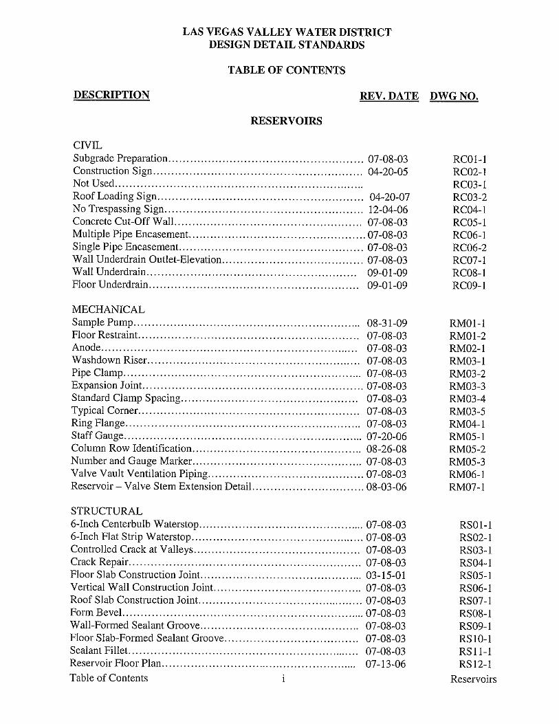
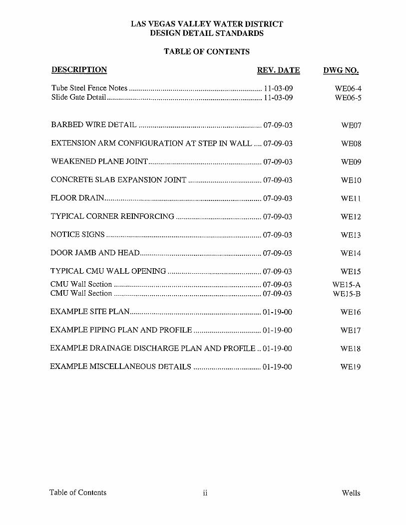
LAS VEGAS VALLEY WATER DISTRICT DESIGN DETAIL STANDARDS
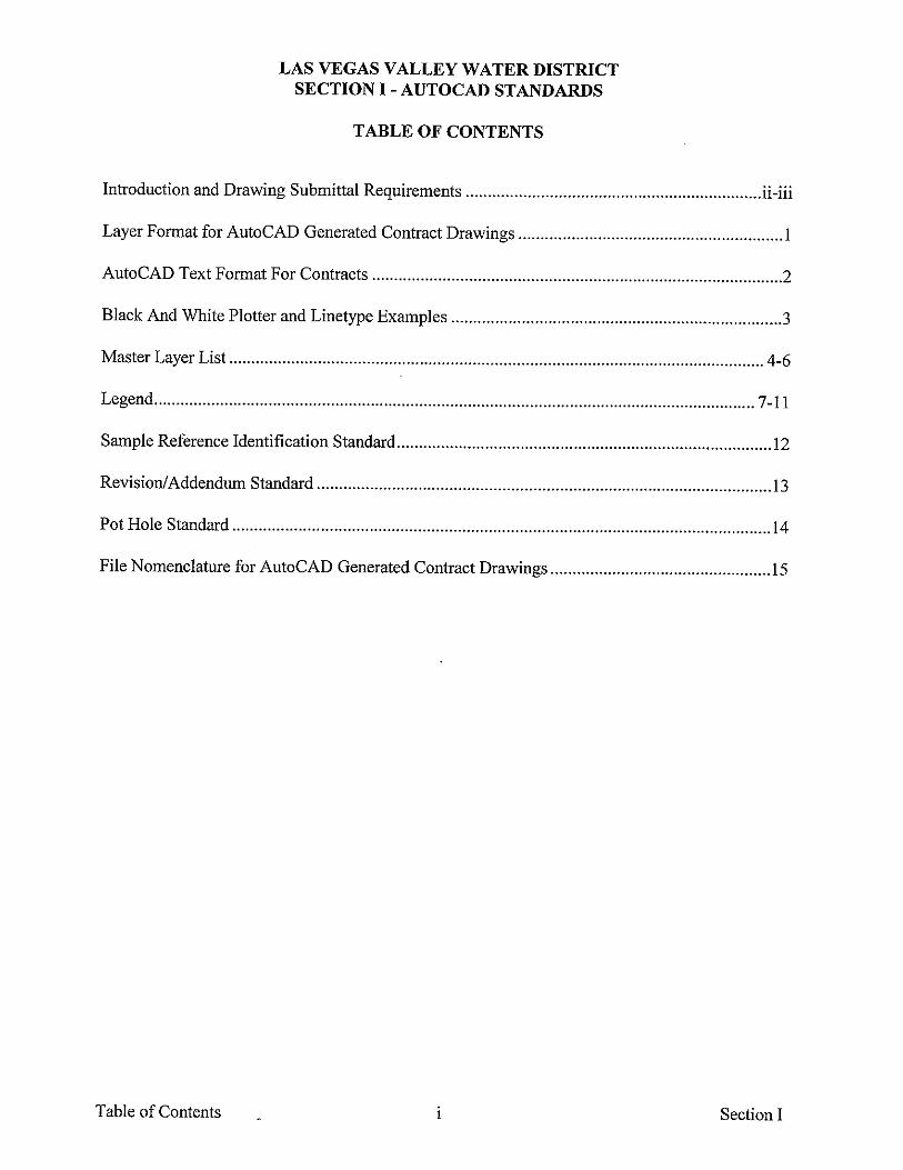
TABLE OF CONTENTS
DESCRIPTION REV. DATE DWG NO.
Table of Contents i General
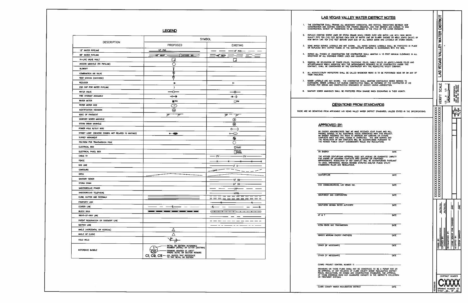
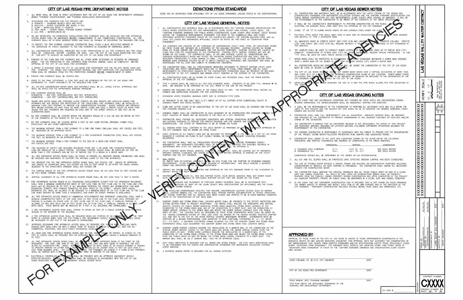
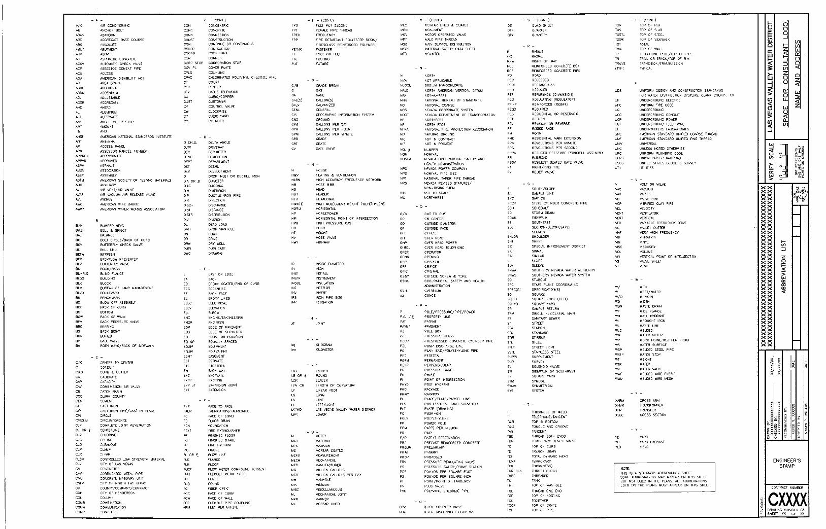
GENERAL Cover Sheet ...................................................................................... 04-12-06 G01 LVVWD General Notes, Legend and Agency Approvals ............... 12-08-09 G02 Clark County General Notes ............................................................ 04-28-10 G03 City of Las Vegas General Notes I .................................................. 06-15-10 G04-1 City of Las Vegas General Notes II ................................................. 06-15-10 G04-2 Abbreviation List ............................................................................. 12-19-01 G05 Estimated Quantities ........................................................................ 11-15-01 G06 Contract Title Block ......................................................................... 11-08-01 Contract-Shell


LAS VEGAS VALLEY WATER DISTRICT DESIGN DETAIL STANDARDS
TABLE OF CONTENTS
DESCRIPTION REV. DATE DWG NO.
Table of Contents i Pipelines
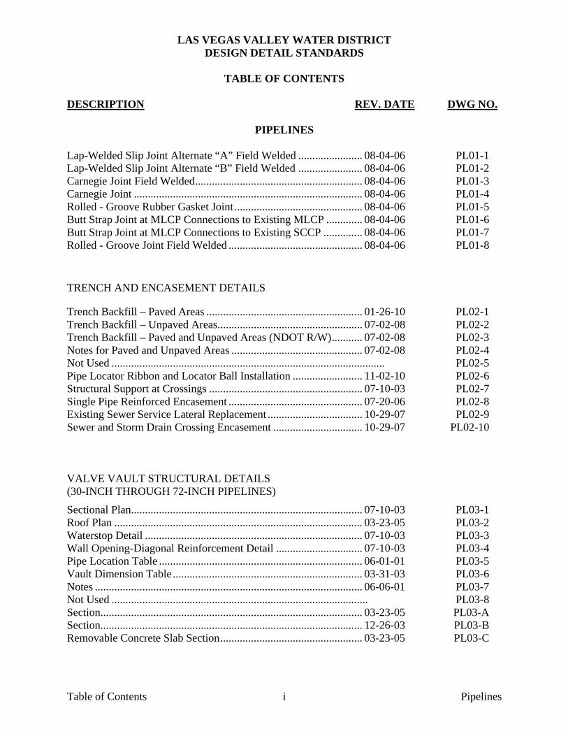
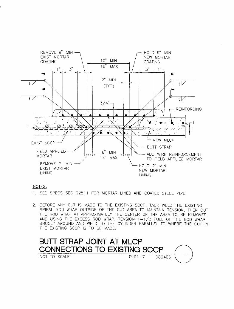
PIPELINES Lap-Welded Slip Joint Alternate “A” Field Welded ....................... 08-04-06 PL01-1 Lap-Welded Slip Joint Alternate “B” Field Welded ....................... 08-04-06 PL01-2 Carnegie Joint Field Welded ............................................................ 08-04-06 PL01-3 Carnegie Joint .................................................................................. 08-04-06 PL01-4 Rolled - Groove Rubber Gasket Joint .............................................. 08-04-06 PL01-5 Butt Strap Joint at MLCP Connections to Existing MLCP ............. 08-04-06 PL01-6 Butt Strap Joint at MLCP Connections to Existing SCCP .............. 08-04-06 PL01-7 Rolled - Groove Joint Field Welded ................................................ 08-04-06 PL01-8 TRENCH AND ENCASEMENT DETAILS
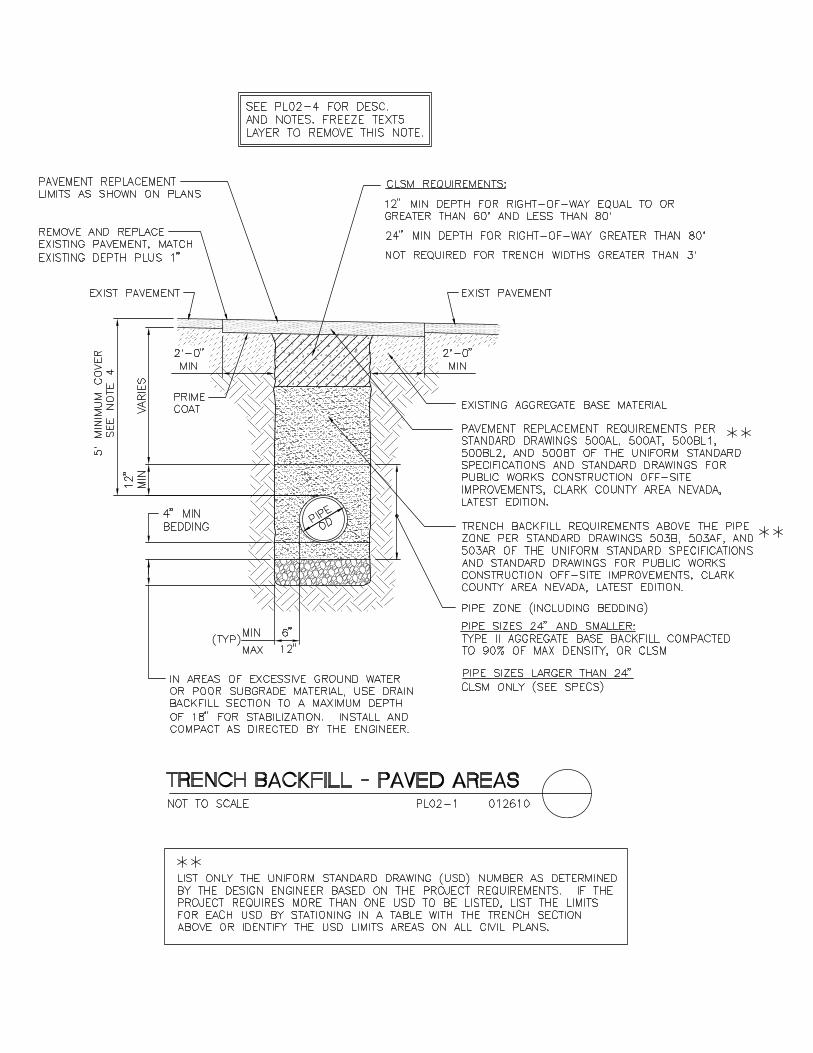
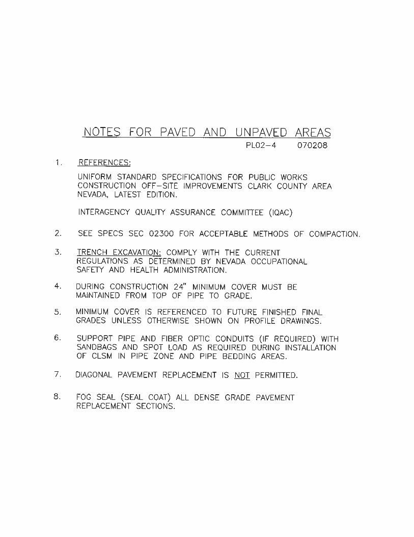
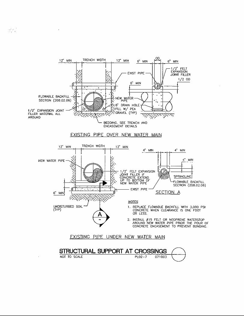
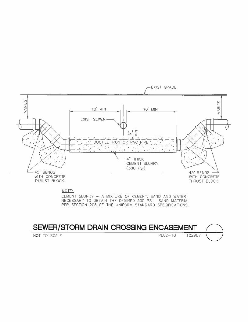
Trench Backfill – Paved Areas ........................................................ 01-26-10 PL02-1 Trench Backfill – Unpaved Areas .................................................... 07-02-08 PL02-2 Trench Backfill – Paved and Unpaved Areas (NDOT R/W) ........... 07-02-08 PL02-3 Notes for Paved and Unpaved Areas ............................................... 07-02-08 PL02-4 Not Used .................................................................................................. PL02-5 Pipe Locator Ribbon and Locator Ball Installation ......................... 11-02-10 PL02-6 Structural Support at Crossings ....................................................... 07-10-03 PL02-7 Single Pipe Reinforced Encasement ................................................ 07-20-06 PL02-8 Existing Sewer Service Lateral Replacement .................................. 10-29-07 PL02-9 Sewer and Storm Drain Crossing Encasement ................................ 10-29-07 PL02-10 VALVE VAULT STRUCTURAL DETAILS (30-INCH THROUGH 72-INCH PIPELINES)
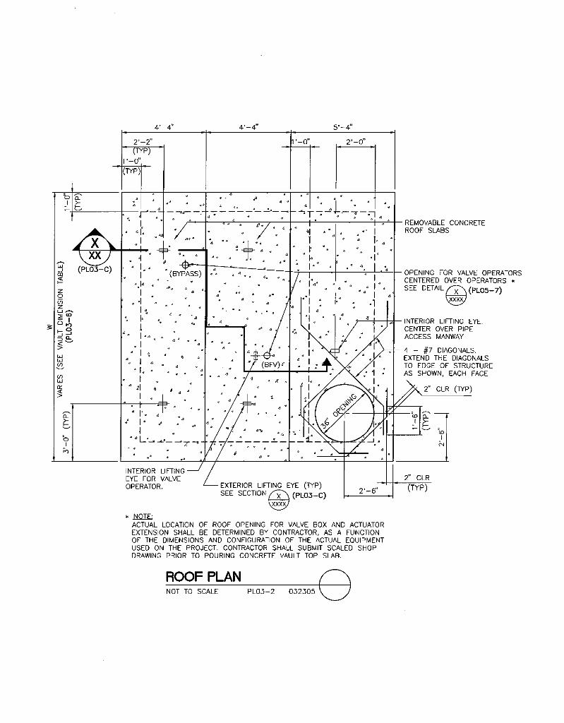
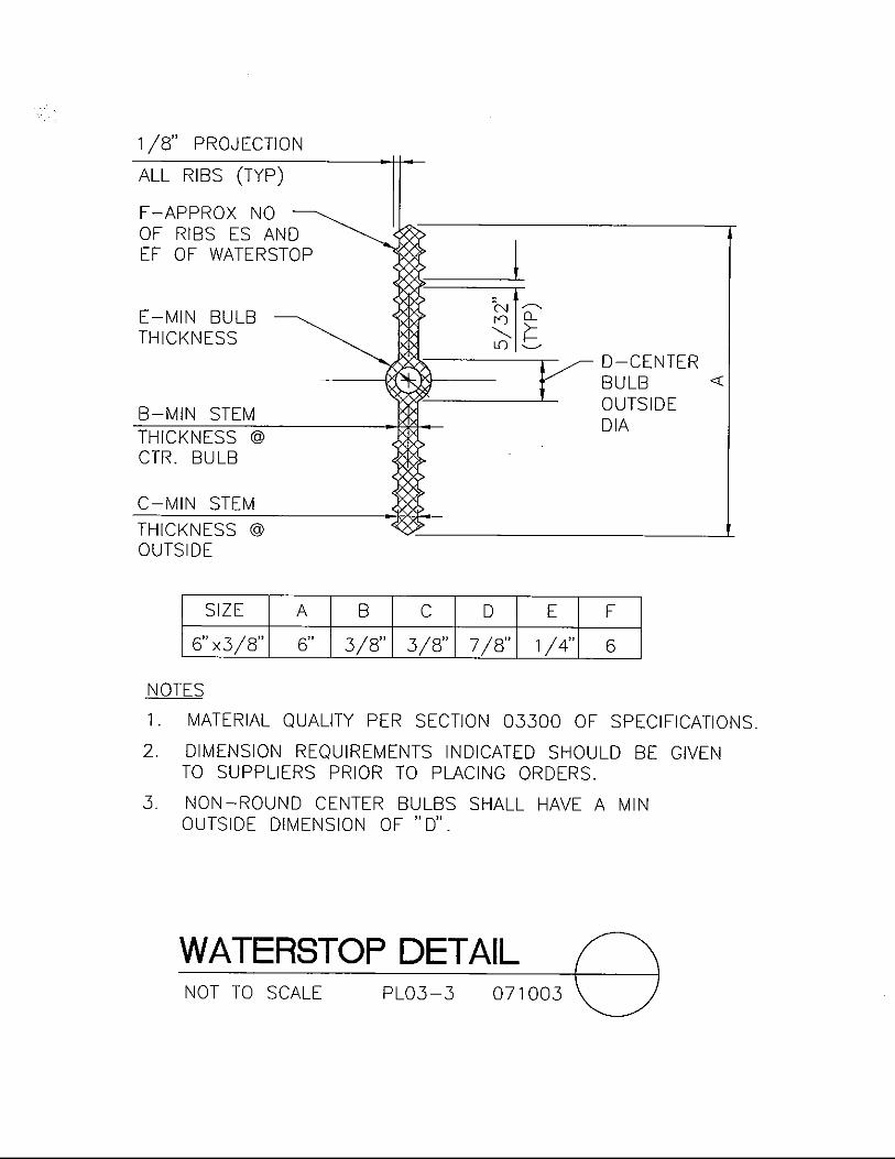
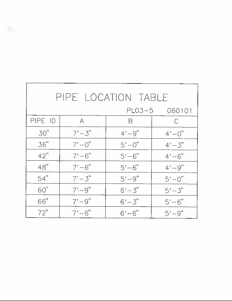
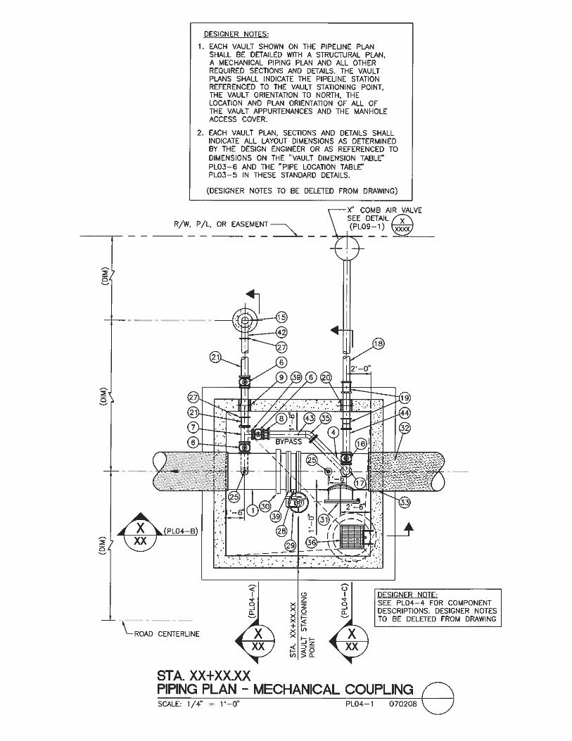
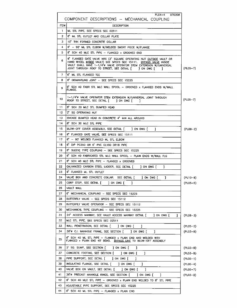
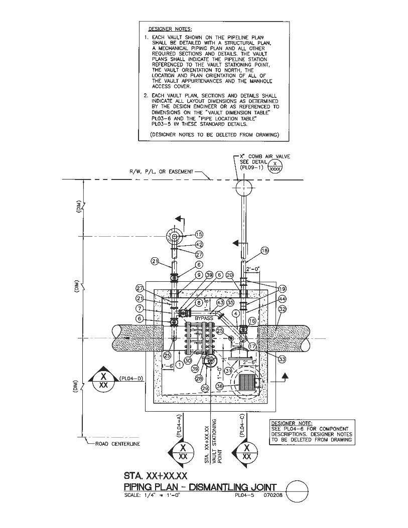
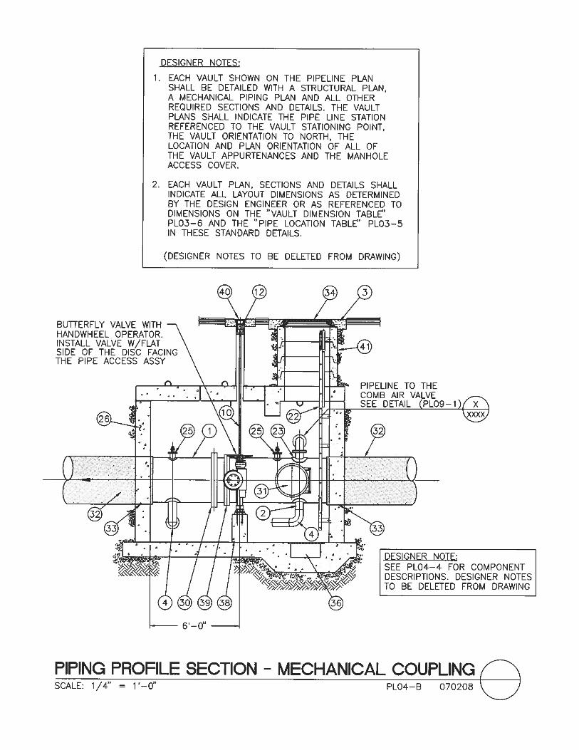
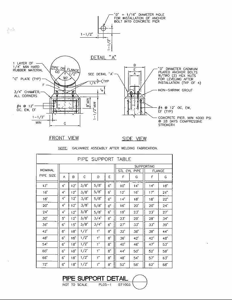
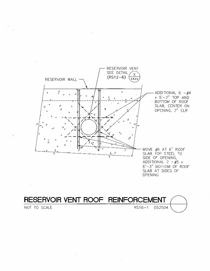
Sectional Plan................................................................................... 07-10-03 PL03-1 Roof Plan ......................................................................................... 03-23-05 PL03-2 Waterstop Detail .............................................................................. 07-10-03 PL03-3 Wall Opening-Diagonal Reinforcement Detail ............................... 07-10-03 PL03-4 Pipe Location Table ......................................................................... 06-01-01 PL03-5 Vault Dimension Table .................................................................... 03-31-03 PL03-6 Notes ................................................................................................ 06-06-01 PL03-7 Not Used ............................................................................................ PL03-8 Section.............................................................................................. 03-23-05 PL03-A Section.............................................................................................. 12-26-03 PL03-B Removable Concrete Slab Section ................................................... 03-23-05 PL03-C


LAS VEGAS VALLEY WATER DISTRICT DESIGN DETAIL STANDARDS
TABLE OF CONTENTS
DESCRIPTION REV. DATE DWG NO.
Table of Contents iv Pipelines
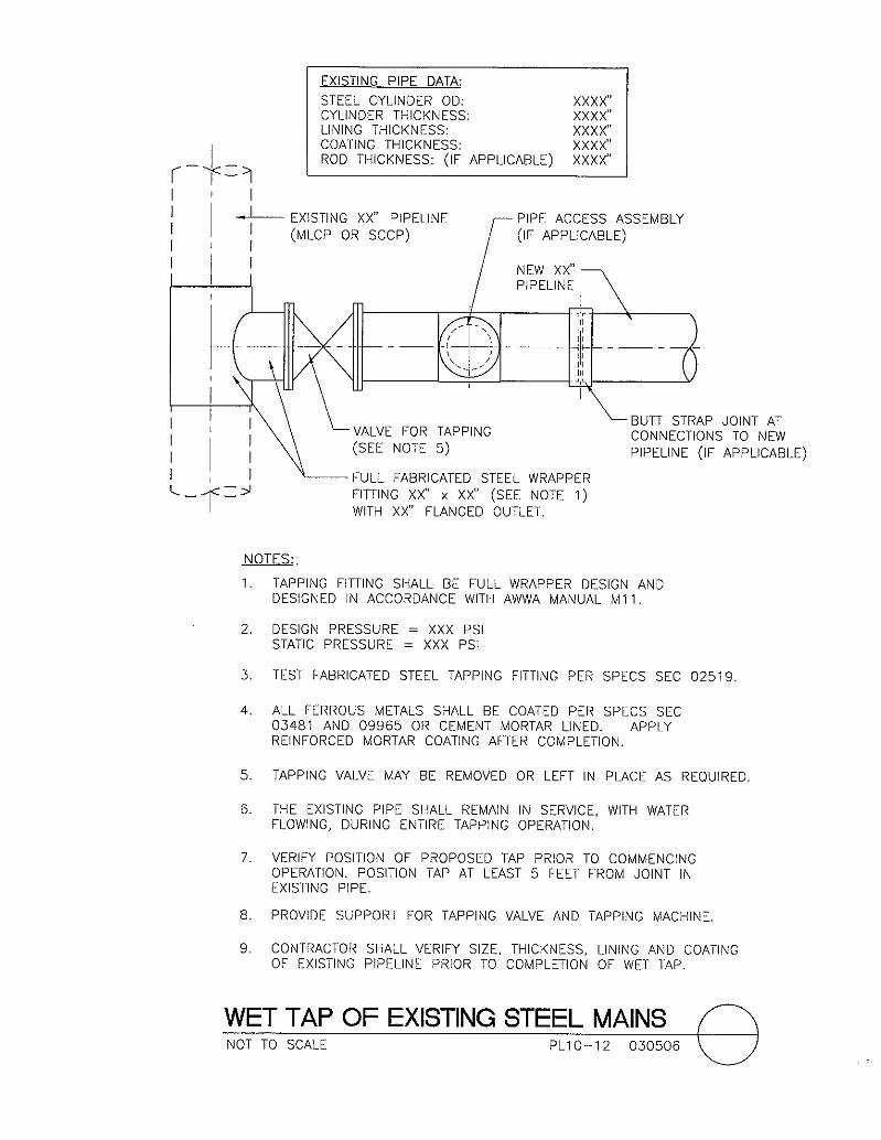
Wet Tap of Existing Steel Mains ..................................................... 03-05-06 PL10-12 Carsonite Marker Installation .......................................................... 09-14-06 PL10-13 THRUST BLOCK, ANCHOR BLOCK, AND CONNECTION DETAILS
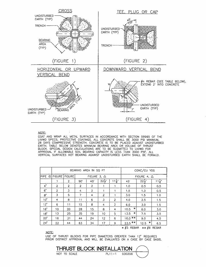
Thrust Block Installation.................................................................. 03-02-06 PL11-1 Anchor Block Details for In-Line Reducers and Gate Valves ......... 03-02-06 PL11-2
CATHODIC PROTECTION DETAILS
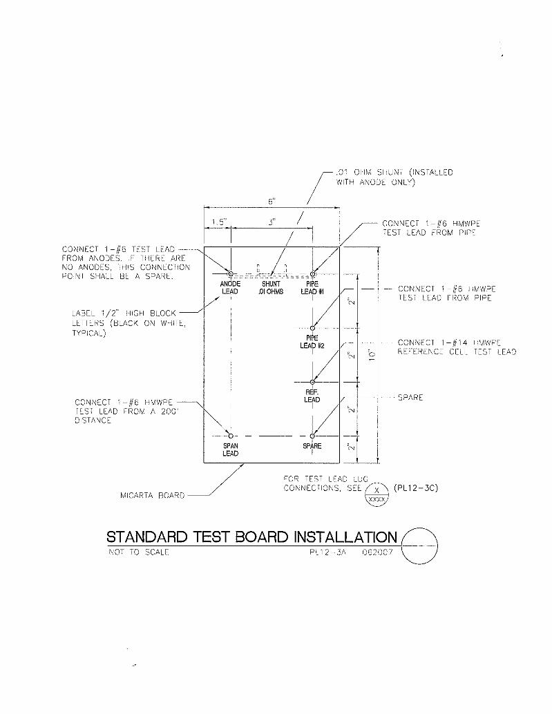
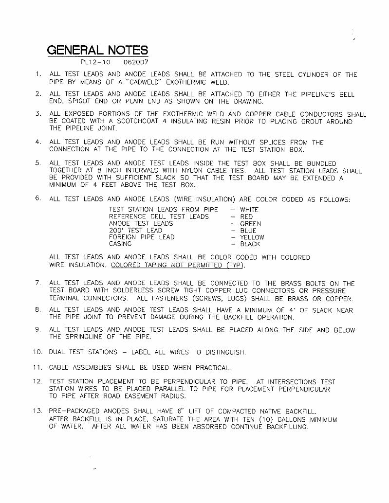
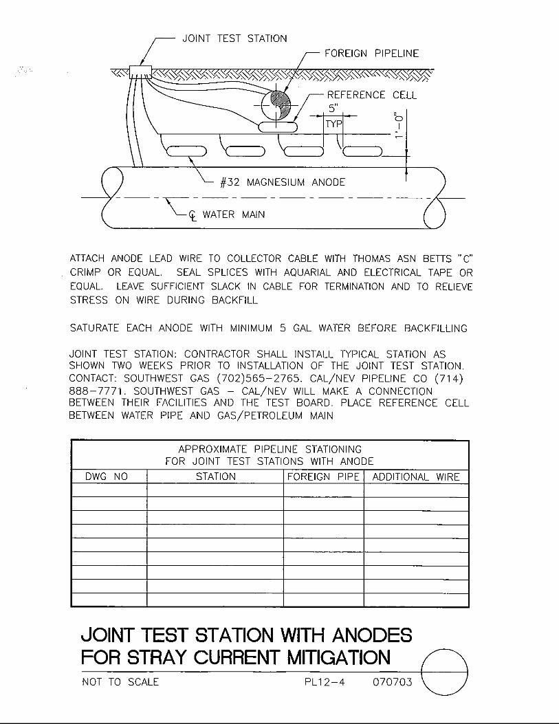
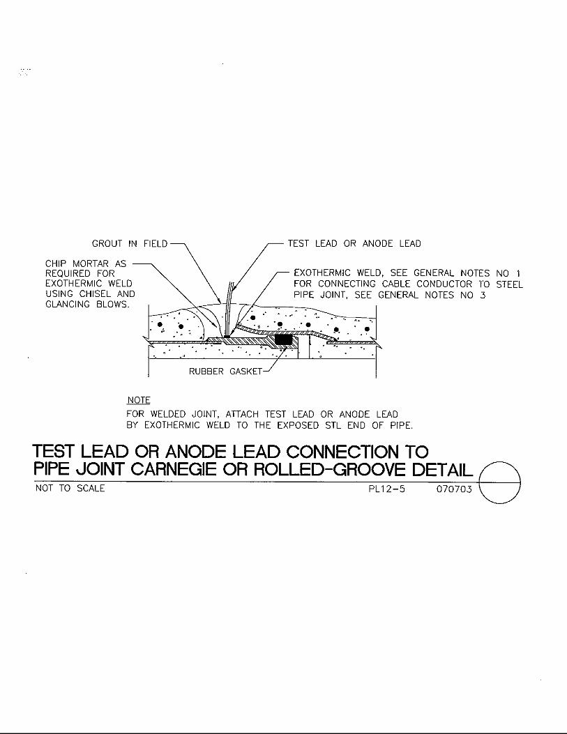
Type “T” Test Station without Anodes ............................................ 03-09-05 PL12-1 Test Box Detail – Typical ................................................................ 09-08-08 PL12-2 Standard Test Board Installation ...................................................... 06-20-07 PL12-3A Test Board for Joint Test Station ..................................................... 06-20-07 PL12-3B Test Board Detail – Typical ............................................................. 07-07-03 PL12-3C Joint Test Station with Anodes for Stray Current Mitigation .......... 07-07-03 PL12-4 Test Lead or Anode Lead Connection to Pipe Joint Carnegie or Rolled – Groove Detail ................................................ 07-07-03 PL12-5 Carnegie Joint Bonding Detail ......................................................... 07-07-03 PL12-6 Bonding Clip Detail ......................................................................... 07-07-03 PL12-7 Rolled – Groove Joint Bonding Detail ............................................. 07-07-03 PL12-8 Push-On Joint Bond Detail Ductile Iron Pipe .................................. 07-07-03 PL12-9 General Notes................................................................................... 10-08-08 PL12-10 Test Station Installation on Existing Pipelines with Pre-Packaged Anodes ...................................................................... 03-12-05 PL12-11 Joint Bonding Detail for Existing SCCP, PCCP, and MCLP .......... 03-12-05 PL12-12 Pre-Packaged Anode Installation Directly on Pipeline .................... 03-12-05 PL12-13
WATER QUALITY SAMPLING STATION
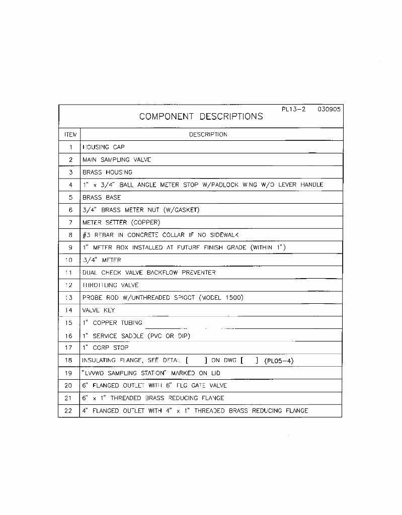
Water Quality Test Station Installation............................................ 11-02-10 PL13-1 Component Descriptions .................................................................. 03-09-05 PL13-2

LAS VEGAS VALLEY WATER DISTRICT DESIGN DETAIL STANDARDS
TABLE OF CONTENTS
DESCRIPTION REV. DATE DWG NO.
Table of Contents v Pipelines
SYSTEM IMPROVEMENTS STANDARD DETAILS
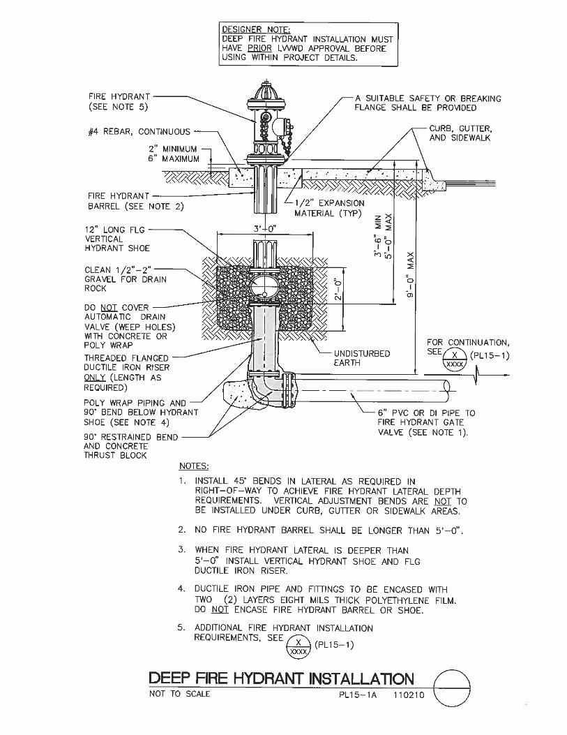
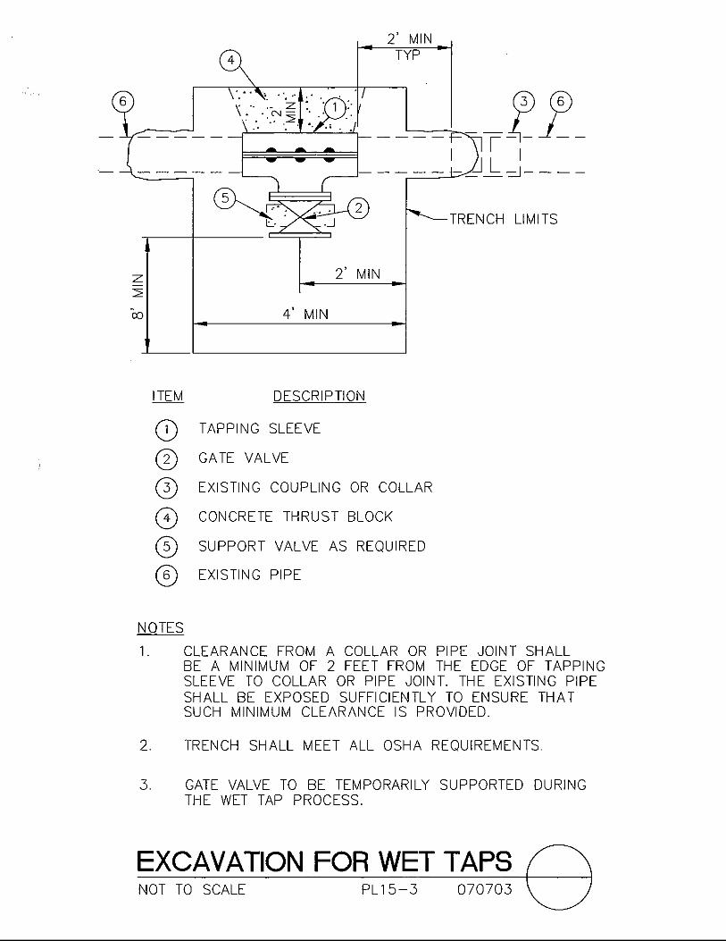
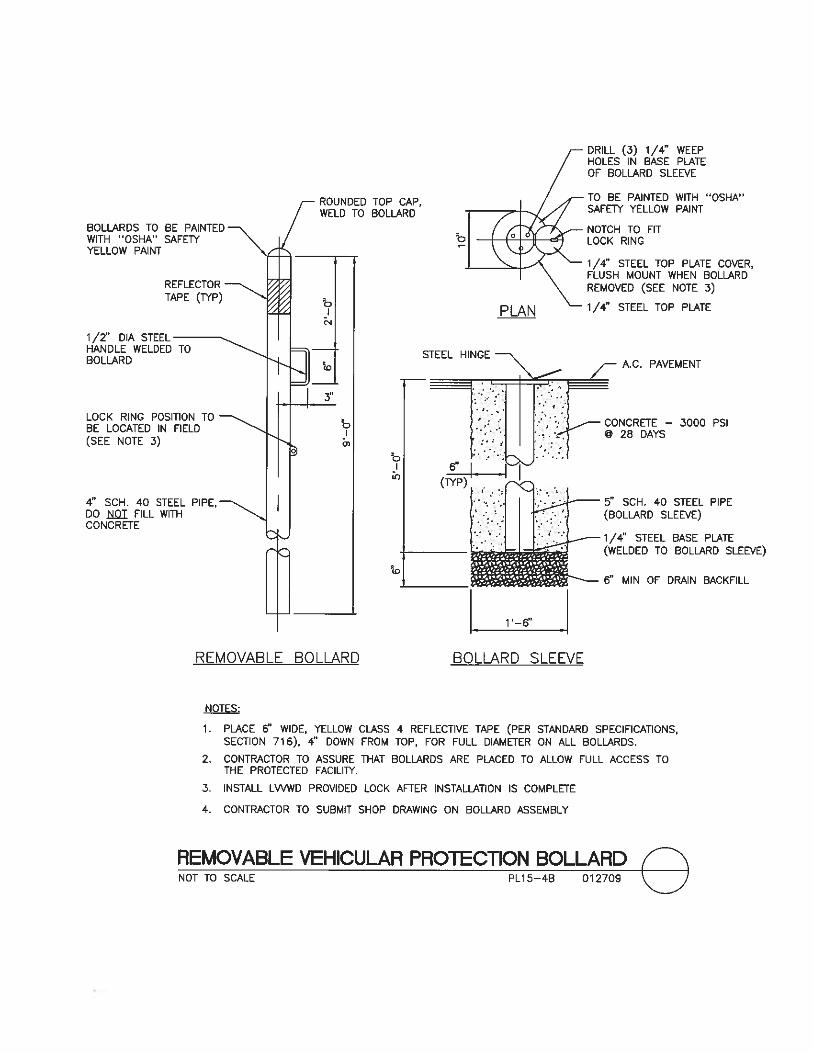
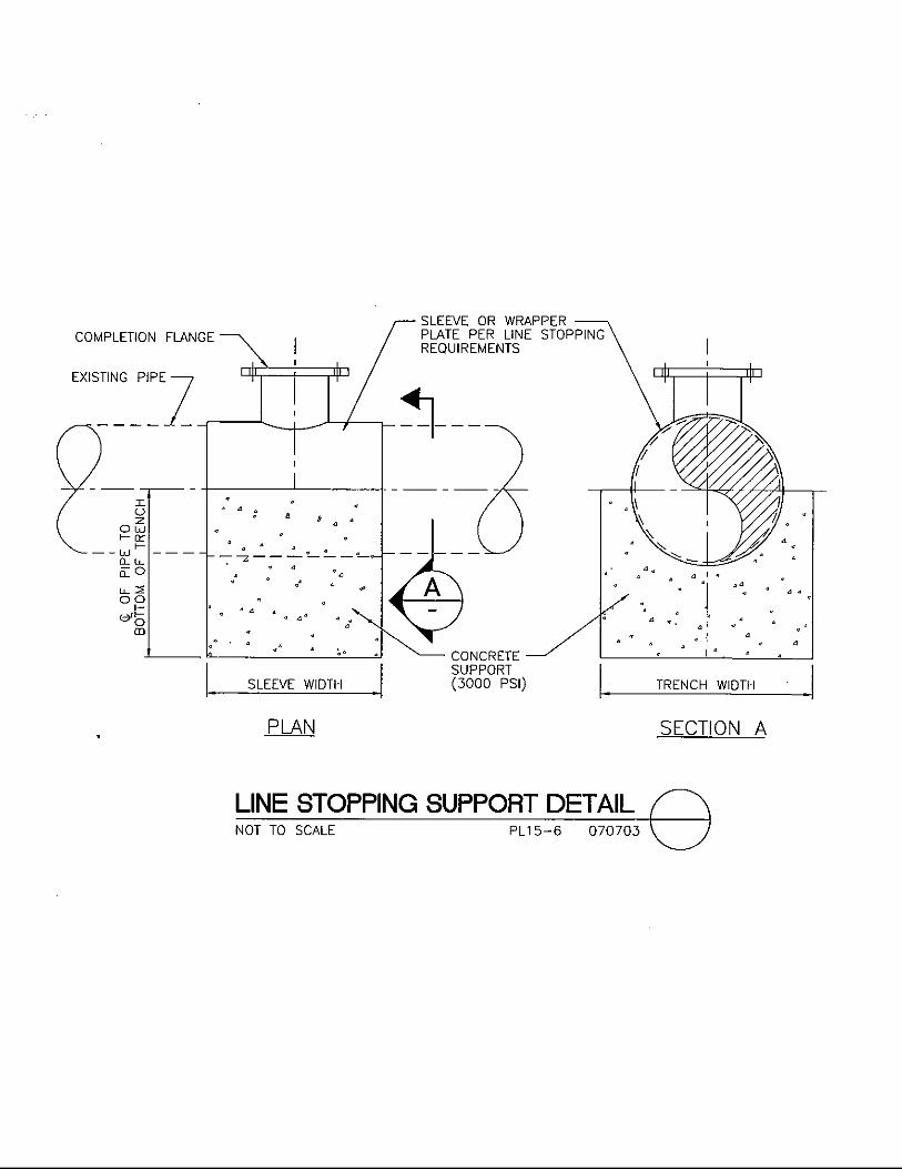
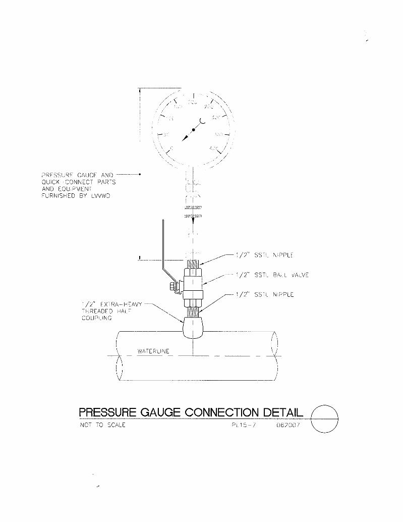
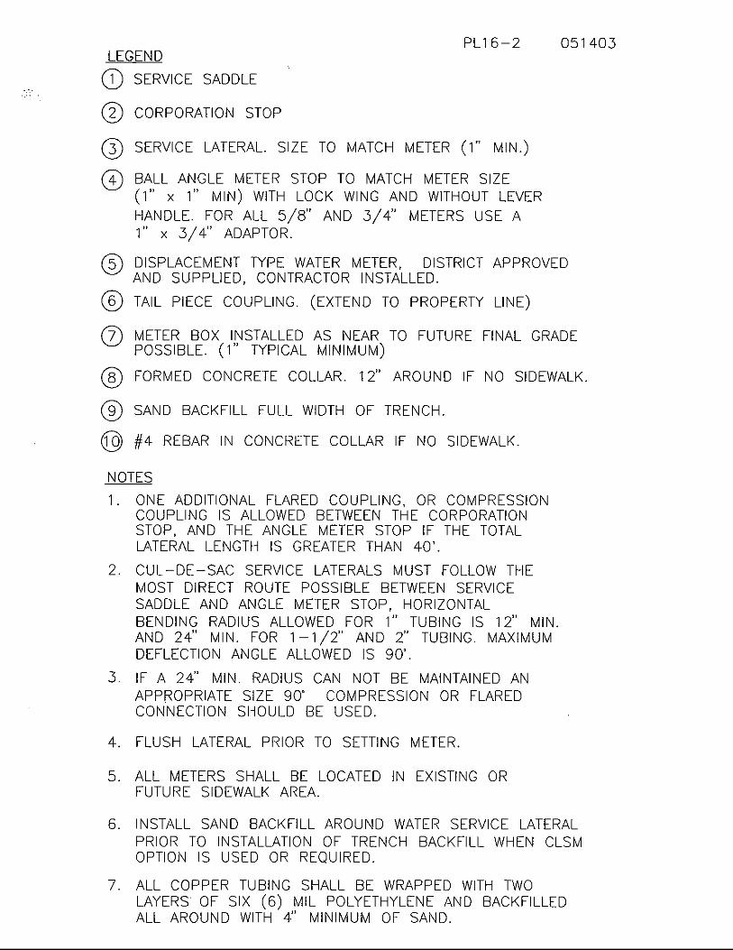
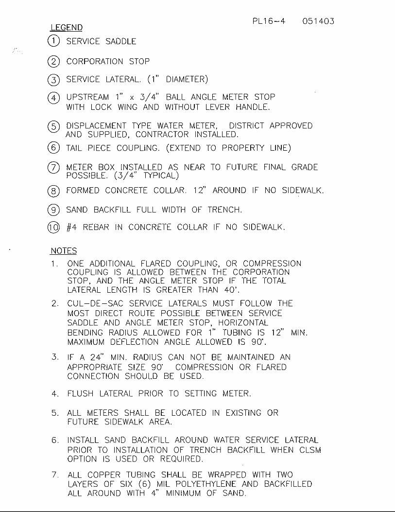
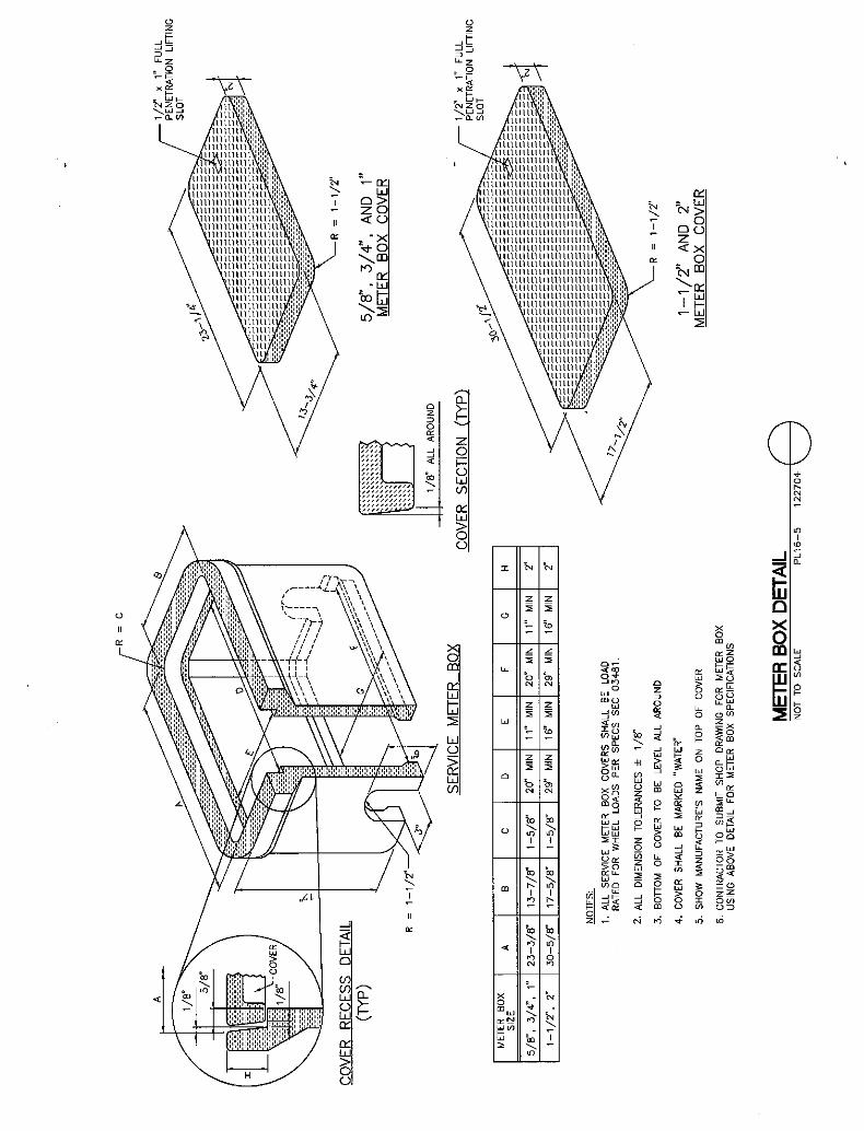
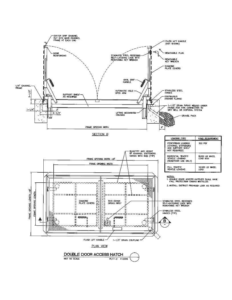
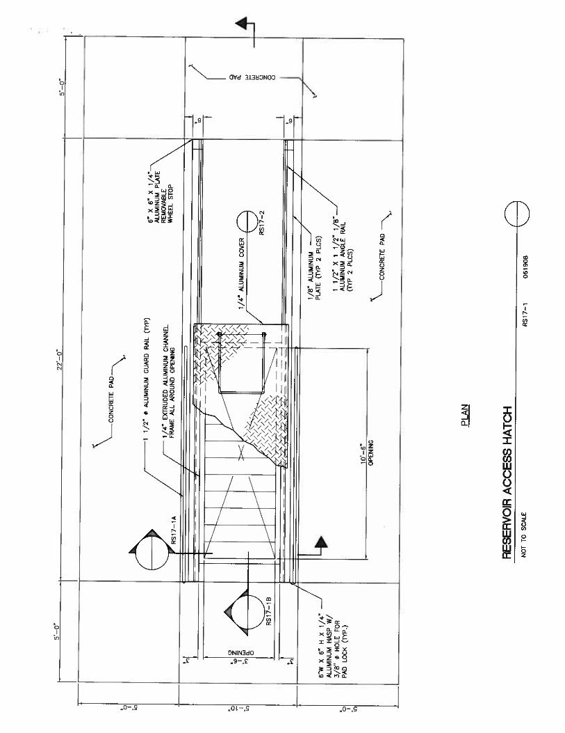
Compact Backflow Assembly .......................................................... 07-07-03 PL14-1 Fire Hydrant Installation .................................................................. 07-07-03 PL15-1 Deep Fire Hydrant Installation ......................................................... 11-02-10 PL15-1A Fire Hydrant Location ...................................................................... 07-07-03 PL15-2 Excavation for Wet Taps ................................................................. 07-07-03 PL15-3 Vehicular Protection Bollard ........................................................... 04-14-05 PL15-4 Notes ................................................................................................ 11-02-01 PL15-5 Line Stopping Support Detail .......................................................... 07-07-03 PL15-6 Pressure Gauge Connection Detail .................................................. 06-20-07 PL15-7 Service Installation for Commercial and Residential Greater Than 1/4 Acre Gross 5/8”, 1”, 1-1/2” and 2” Meter Sizes ............... 07-07-03 PL16-1 Legend and Notes ............................................................................ 05-14-03 PL16-2 Service Installation for Residential Less Than or Equal to 1/4 Acre Gross 5/8” and 3/4” Meter Sizes ....................................... 07-07-03 PL16-3 Legend and Notes ............................................................................ 05-14-03 PL16-4 Meter Box Detail.............................................................................. 12-27-04 PL16-5 Single Door Access Hatch ............................................................... 11-23-09 PL17-1 Double Door Access Hatch .............................................................. 11-23-09 PL17-2 Existing Vault Structure Abandonment ........................................... 11-10-03 PL18-1


LAS VEGAS VALLEY WATER DISTRICT DESIGN DETAIL STANDARDS
TABLE OF CONTENTS
DESCRIPTION REV. DATE DWG NO.
Table of Contents i Wells
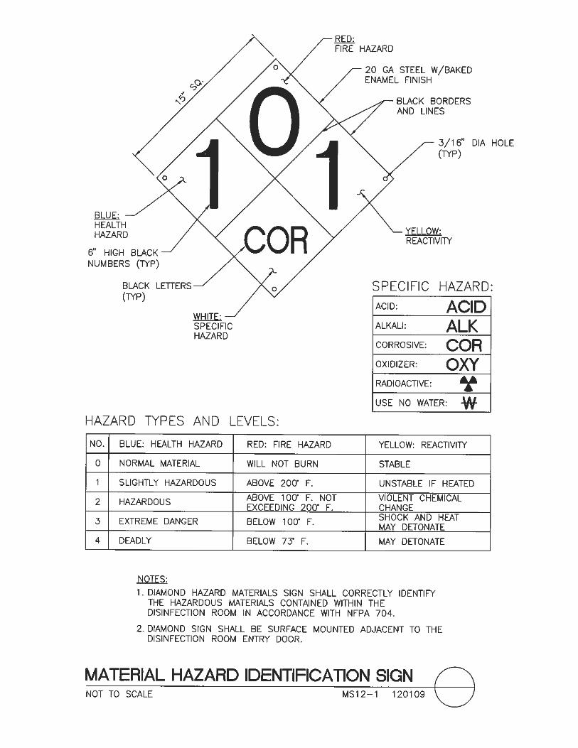
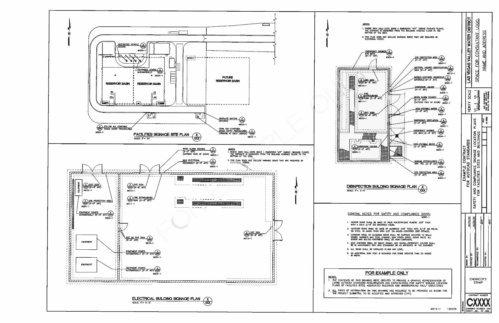
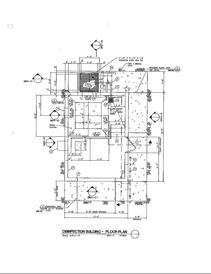
WELLS DISINFECTION BUILDING
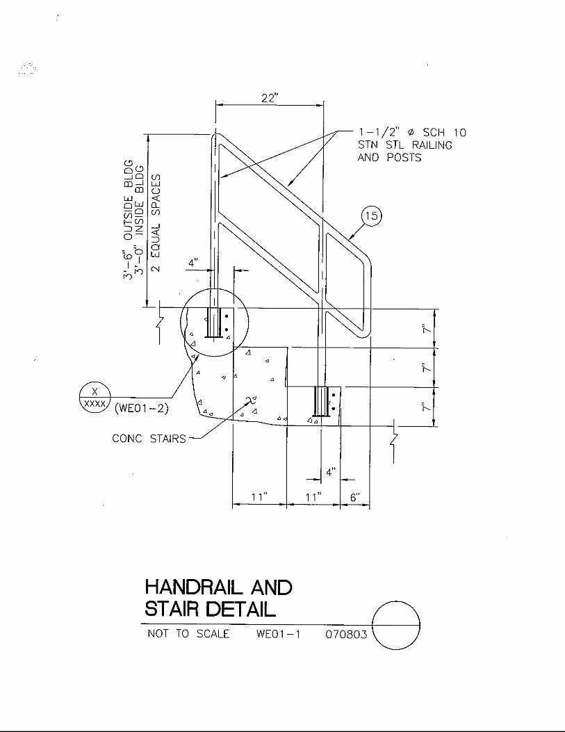
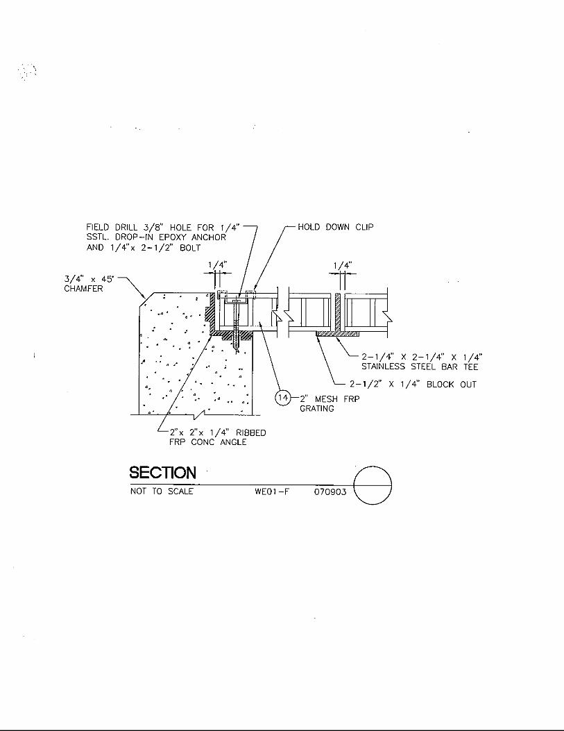
Handrail and Stair Detail ................................................................. 07-08-03 WE01-1 Post Insert in Concrete Detail .......................................................... 07-08-03 WE01-2 Disinfection Building – Floor Plan.................................................. 07-08-03 WE01-3 Items Description ............................................................................. 01-24-01 WE01-4 Elevation .......................................................................................... 07-09-03 WE01-A Elevation .......................................................................................... 07-09-03 WE01-B Section.............................................................................................. 07-09-03 WE01-C Section.............................................................................................. 07-09-03 WE01-D Elevation .......................................................................................... 07-09-03 WE01-E Section.............................................................................................. 07-09-03 WE01-F
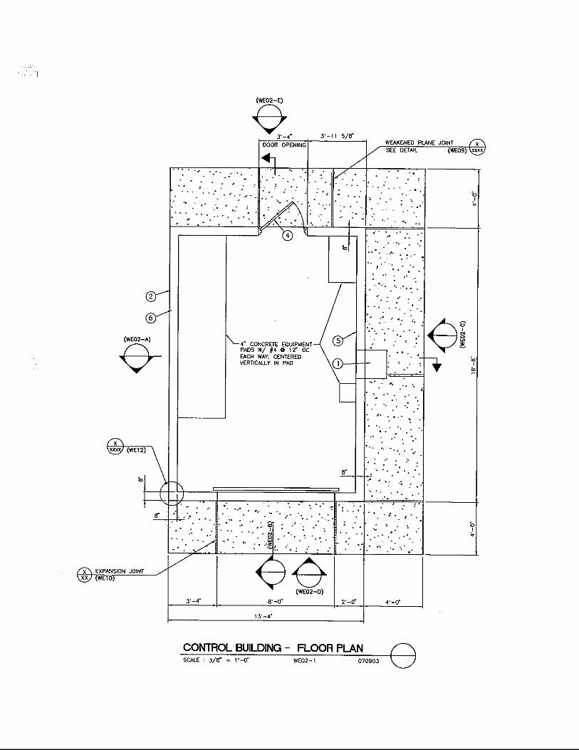
CONTROL BUILDING
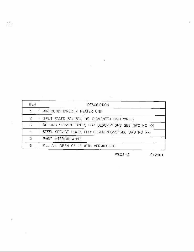
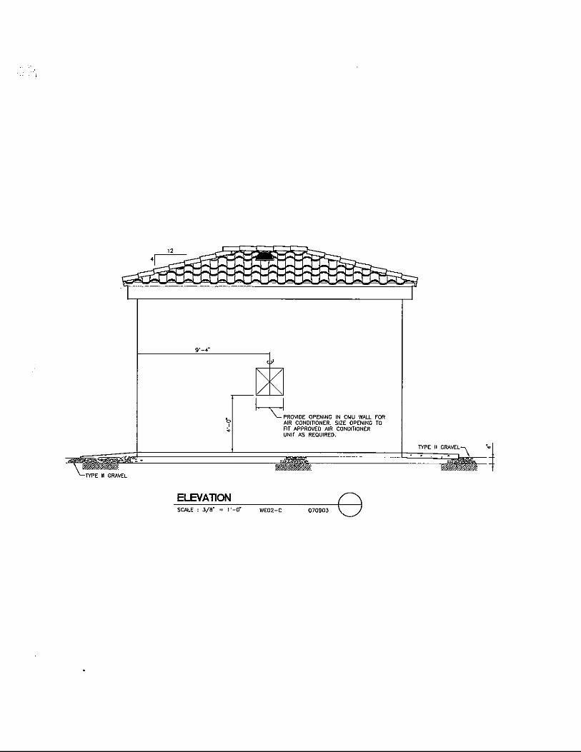
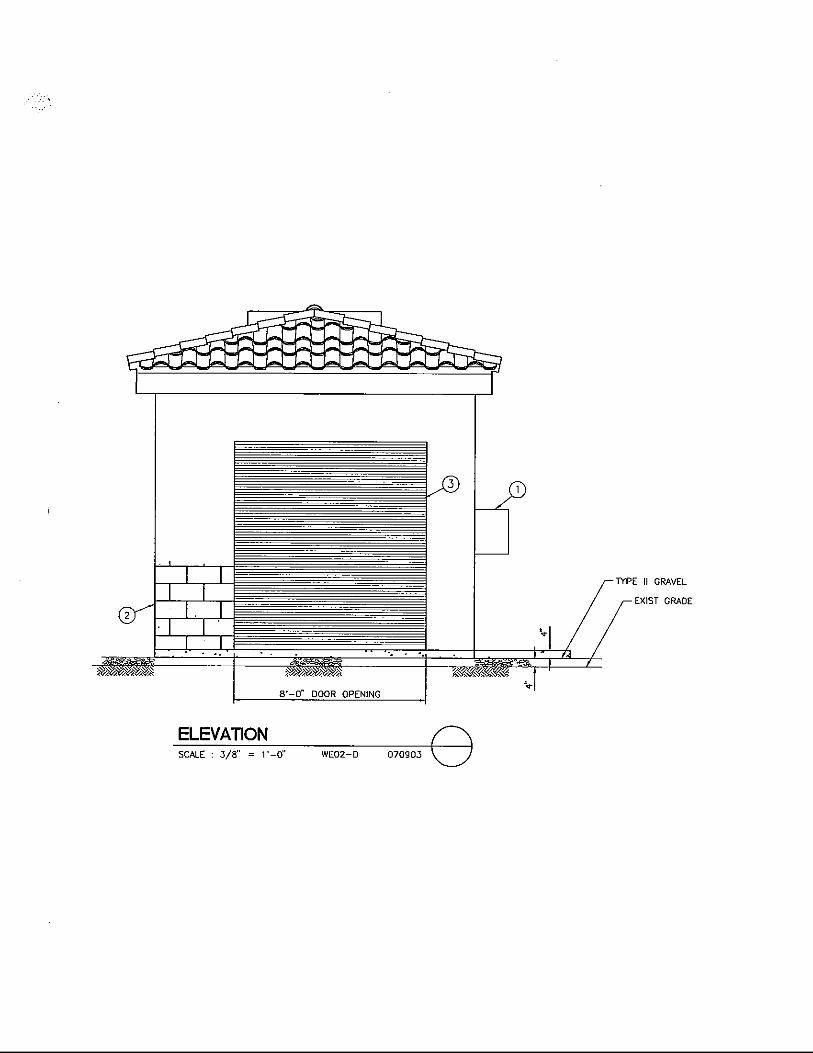
Control Building – Floor Plan ......................................................... 07-09-03 WE02-1 Items Description ............................................................................. 01-24-01 WE02-2 Section.............................................................................................. 07-09-03 WE02-A Section.............................................................................................. 07-09-03 WE02-B Elevation .......................................................................................... 07-09-03 WE02-C Elevation .......................................................................................... 07-09-03 WE02-D Elevation .......................................................................................... 07-09-03 WE02-E DISINFECTION SOLUTION PIPING
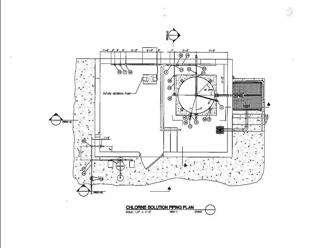
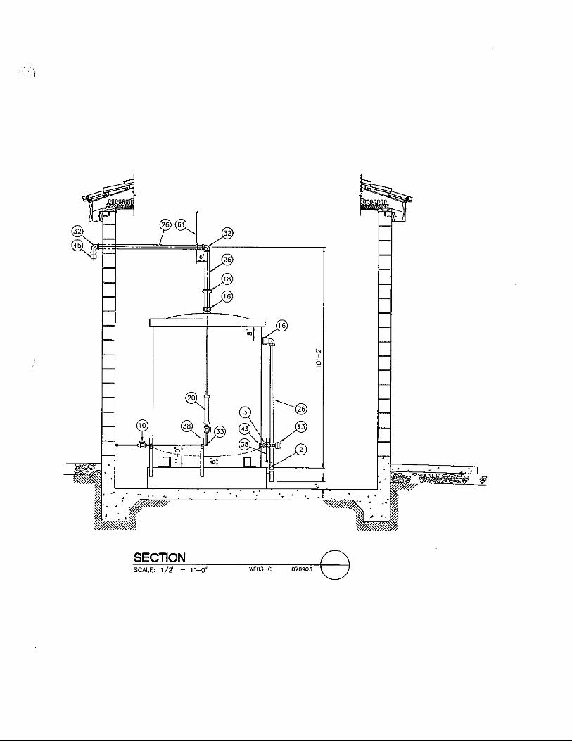
Chlorine Solution Piping Plan ......................................................... 07-09-03 WE03-1 Items Description ............................................................................. 01-24-01 WE03-2 Section.............................................................................................. 07-09-03 WE03-A Section.............................................................................................. 07-09-03 WE03-B Section.............................................................................................. 07-09-03 WE03-C ROOF FRAMING
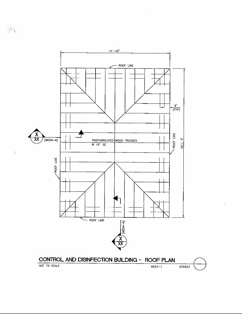
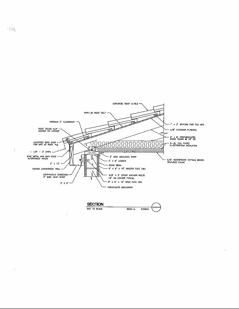
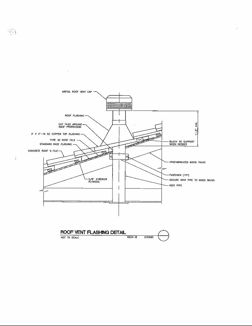
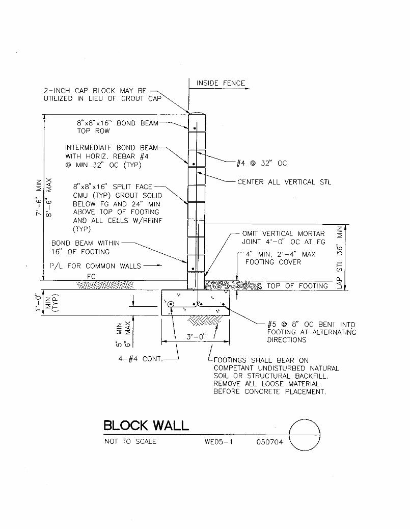
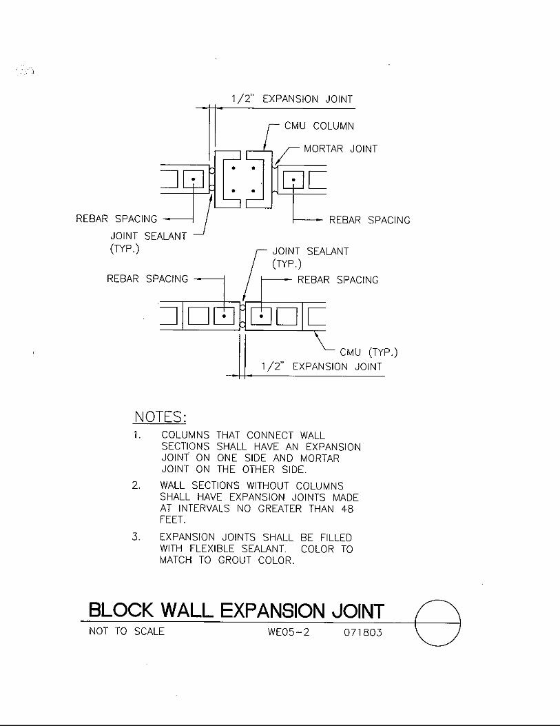
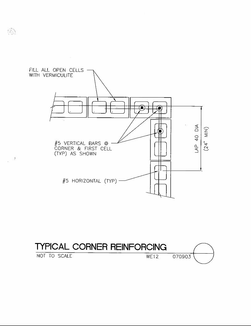
Control and Disinfection Building – Roof Plan............................... 07-09-03 WE04-1 Section.............................................................................................. 07-09-03 WE04-A Roof Vent Flashing Detail ............................................................... 07-09-03 WE04-B Block Wall ....................................................................................... 05-07-04 WE05-1 Block Wall Expansion Joint………………………………………. 07-18-03 WE05-2 Typical Footing at Step……………………………………............ 05-07-04 WE05-3 Swing Gate Detail ............................................................................ 12-21-09 WE06-1 Down Rod Assembly ....................................................................... 11-03-09 WE06-2 Down Rod Detail ............................................................................. 11-03-09 WE06-3


LAS VEGAS VALLEY WATER DISTRICT DESIGN DETAIL STANDARDS
TABLE OF CONTENTS
DESCRIPTION REV. DATE DWG NO.
Table of Contents iii Electrical
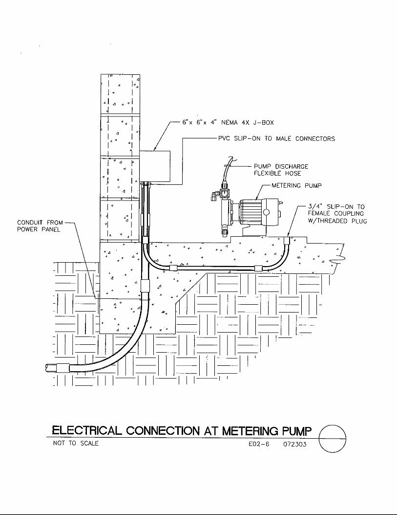
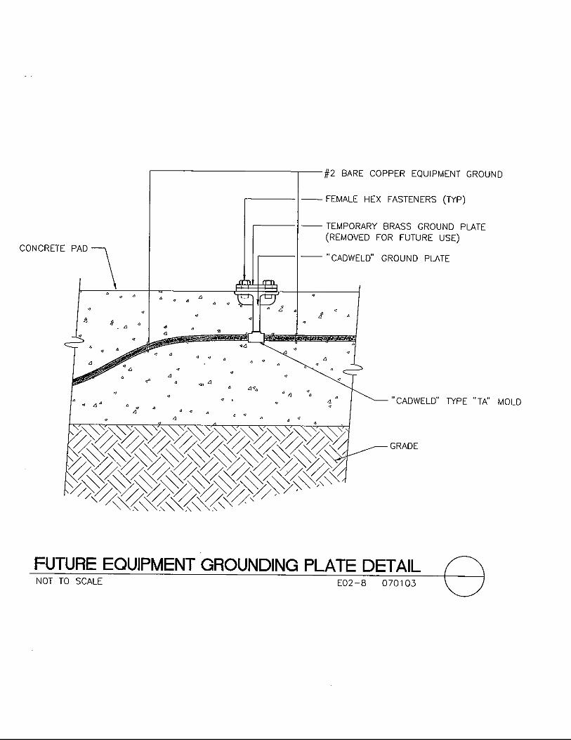
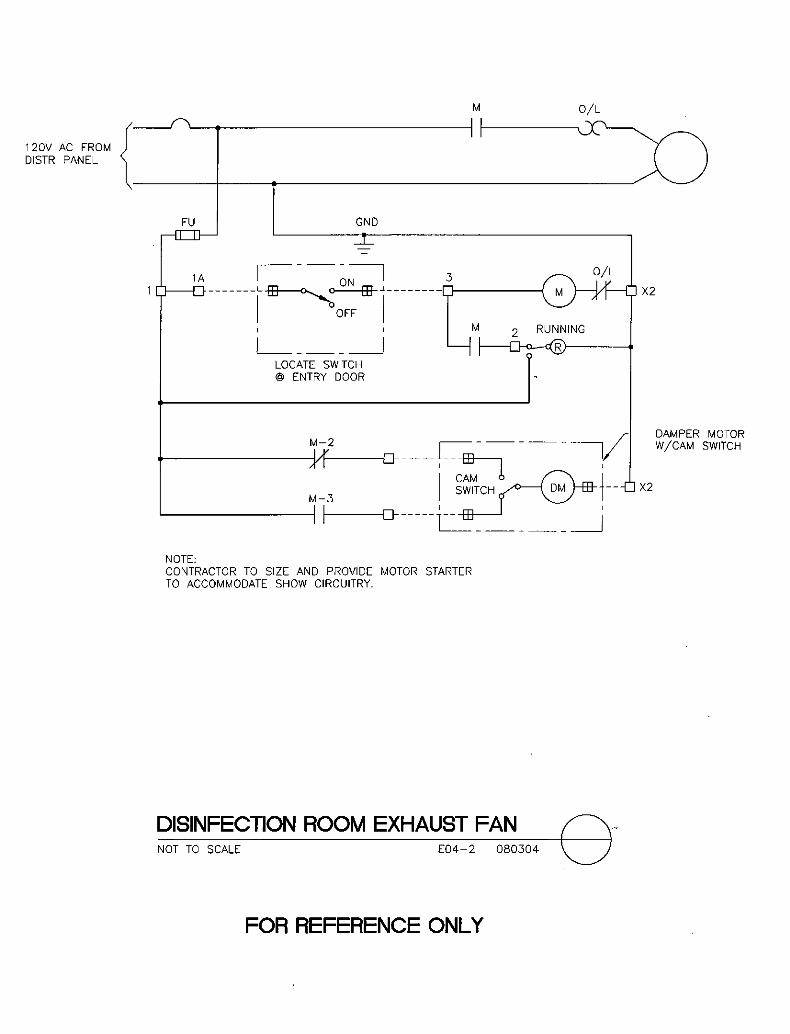
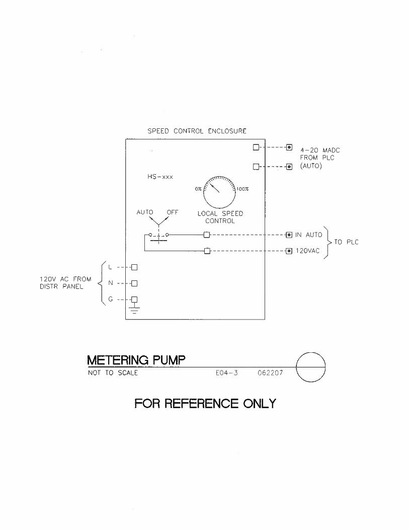
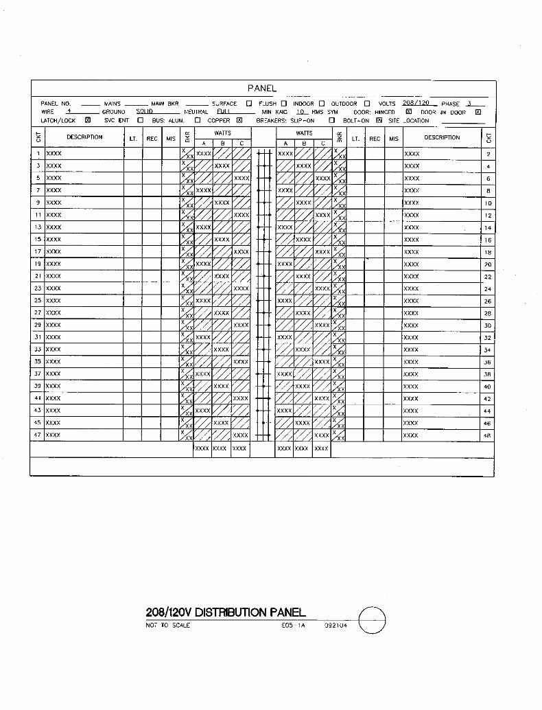
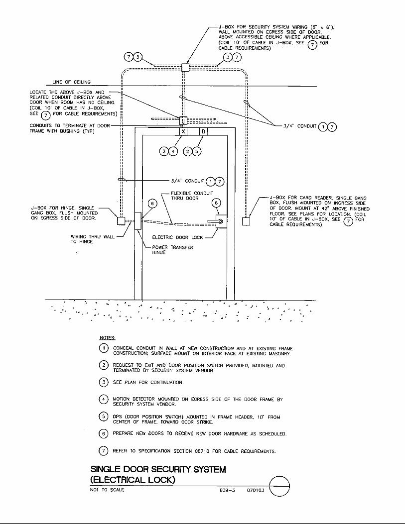
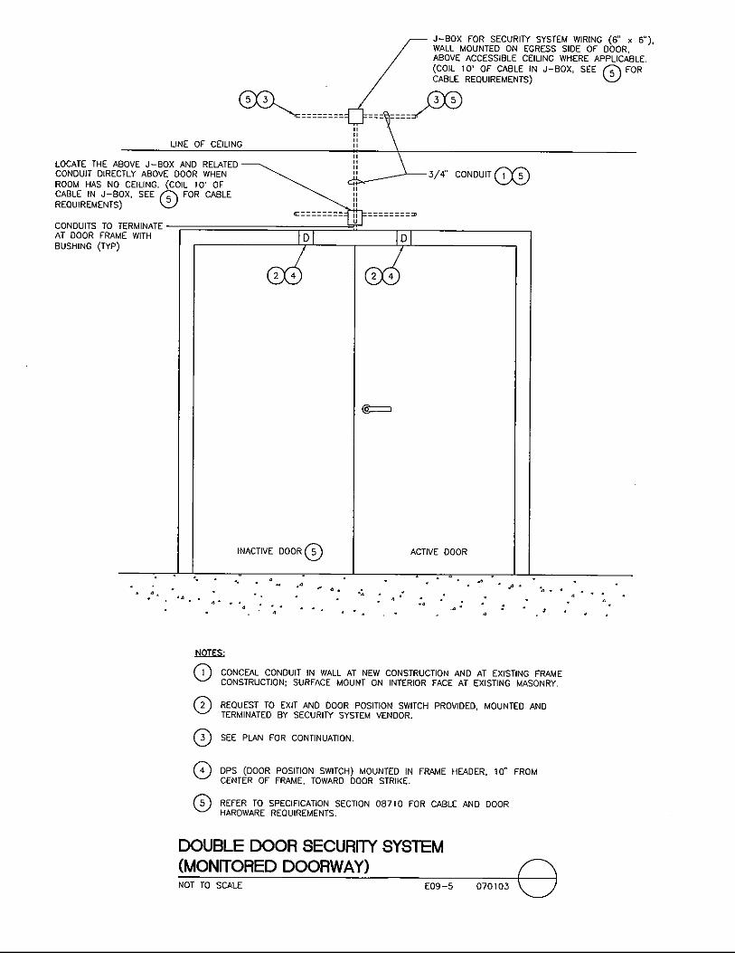
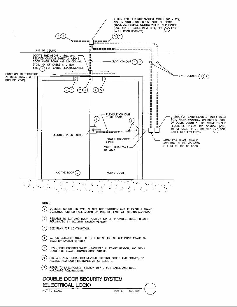
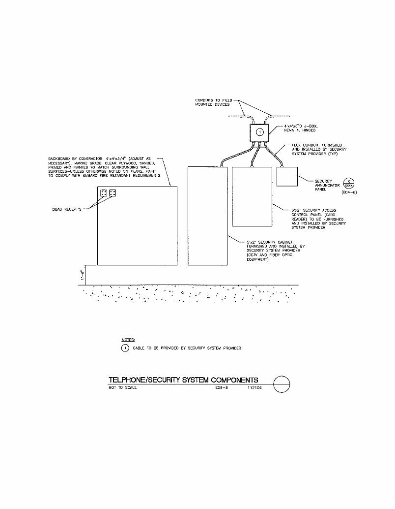
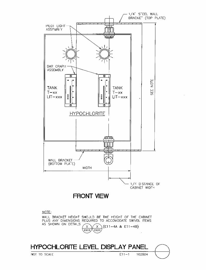
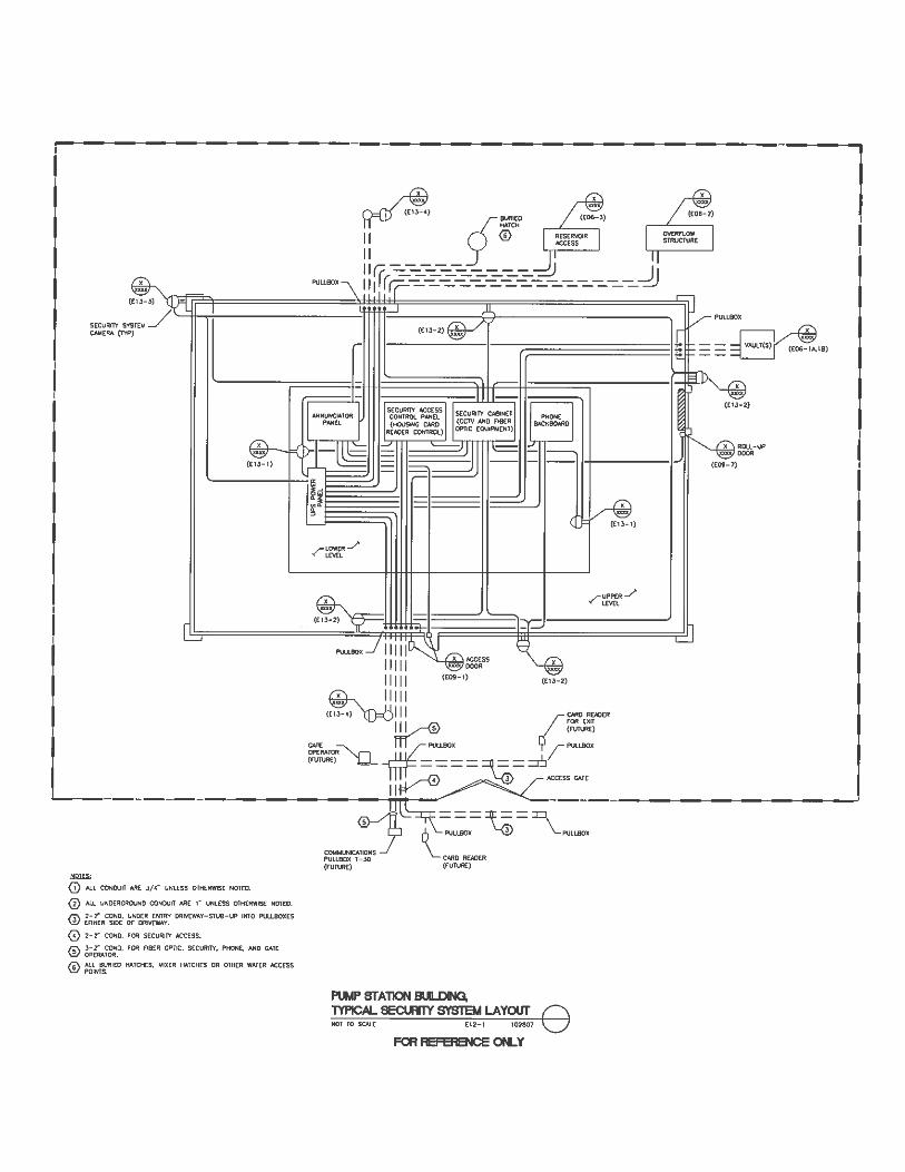
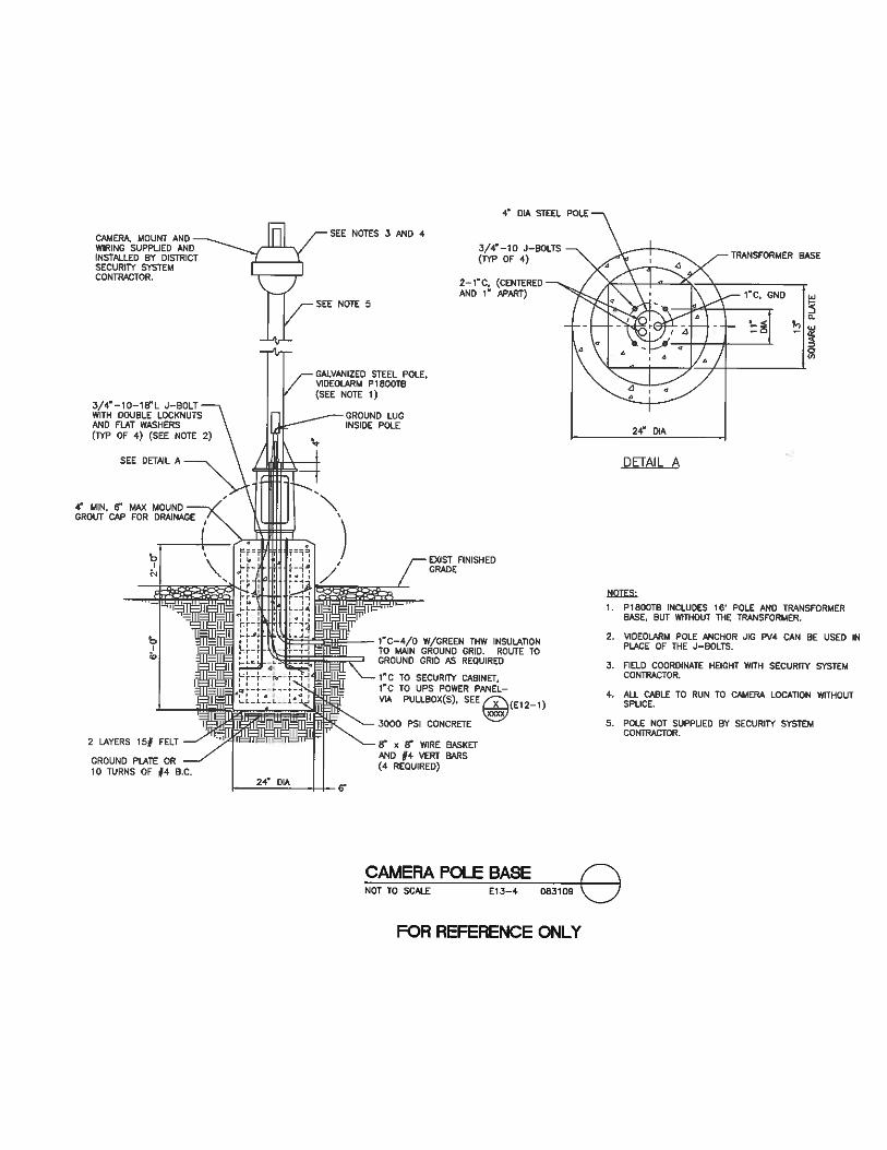
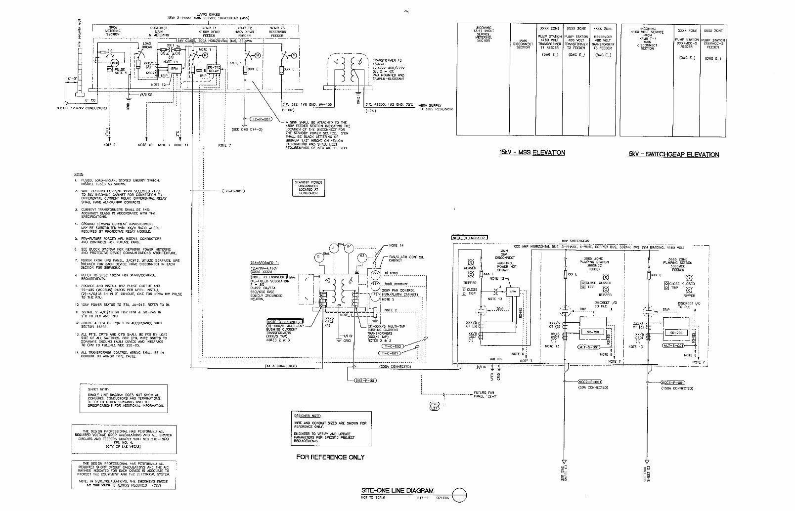
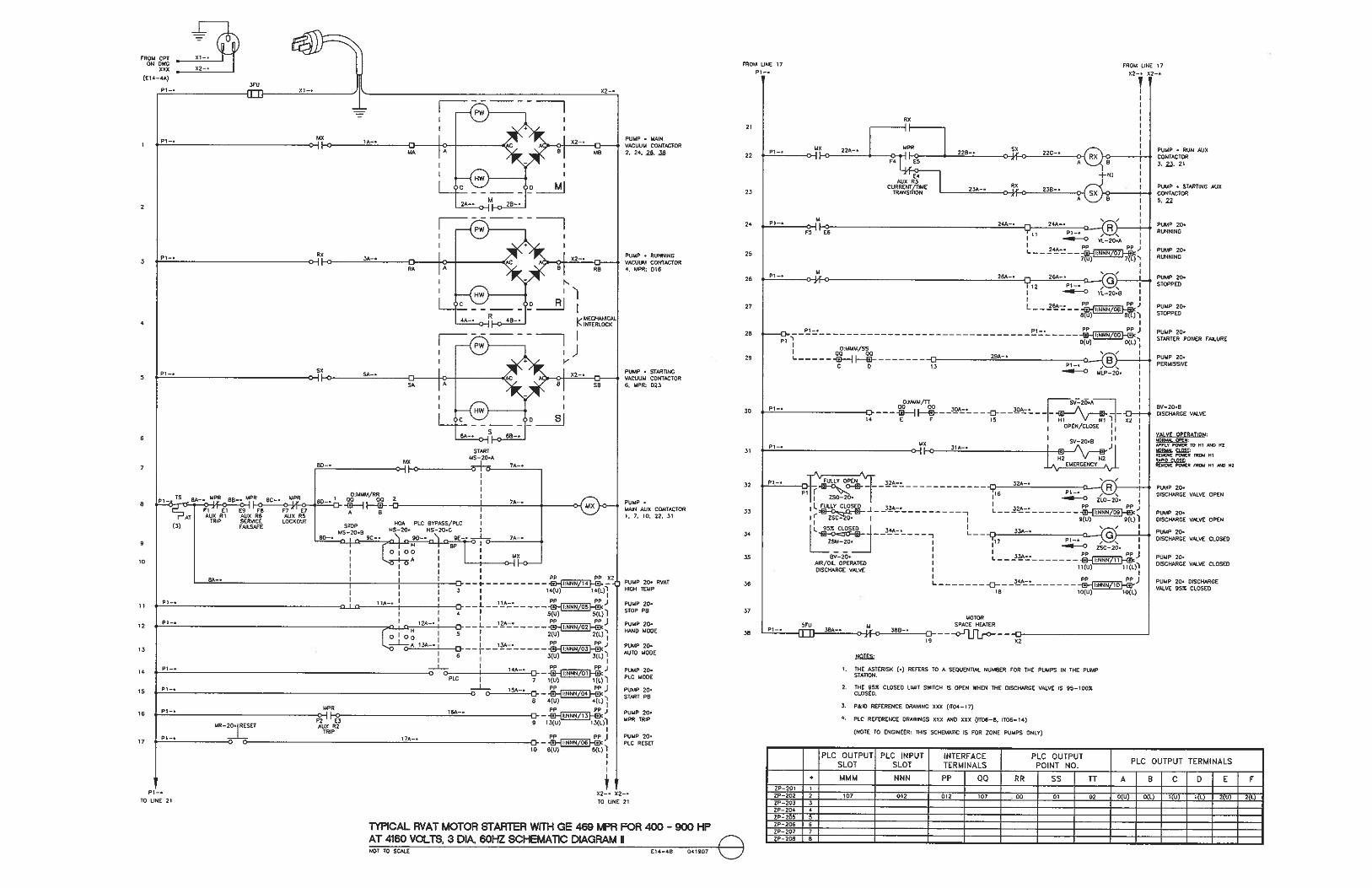
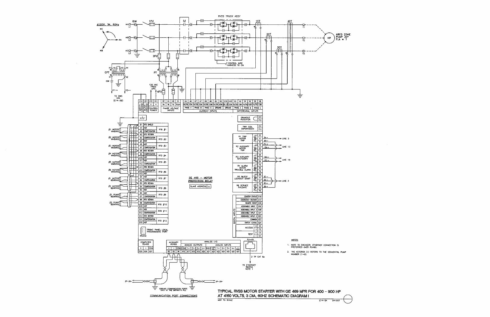
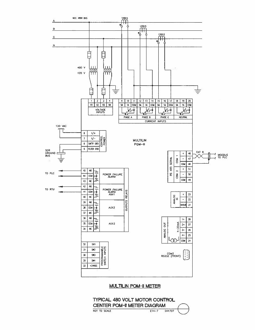
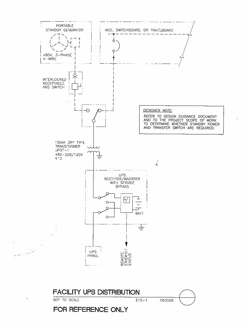
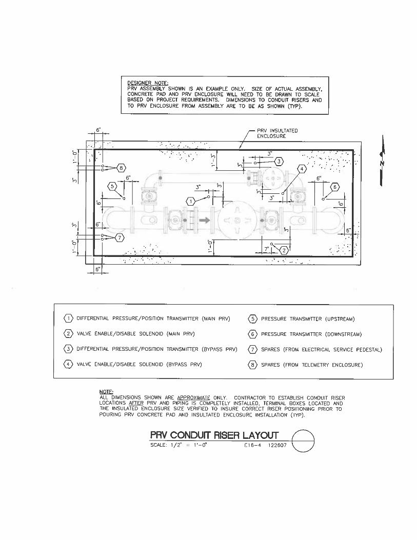
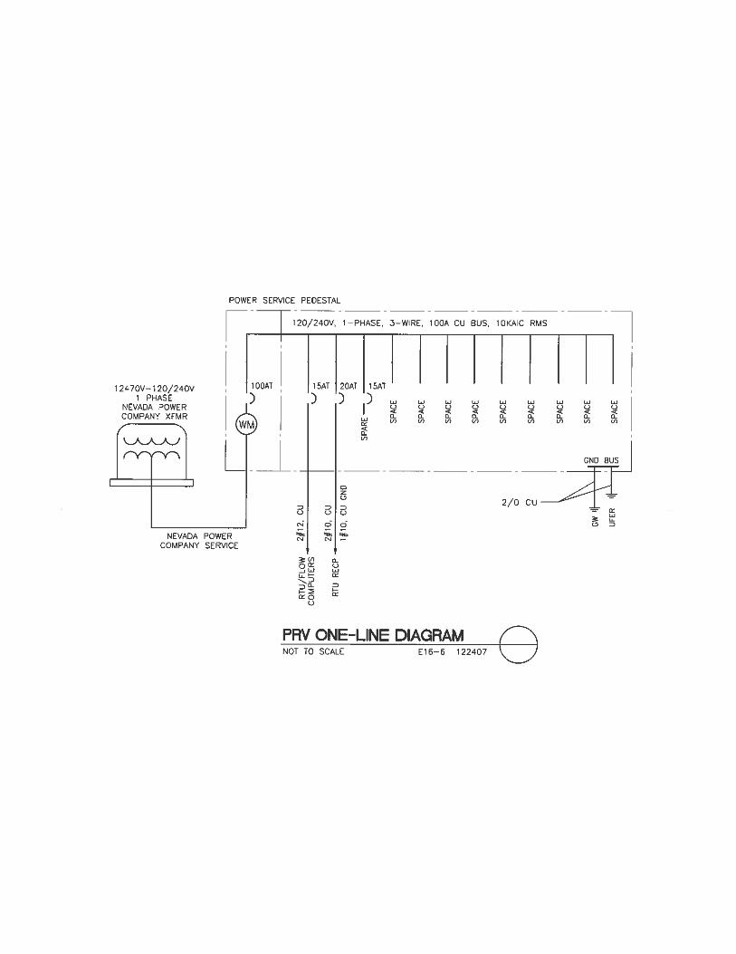
Pump Station Building Typical Security System Layout ................ 10-28-07 E12-1 Security System Interior Ceiling Mount Camera............................. 10-29-07 E13-1 Security System Interior and Exterior Wall Mount Camera ............ 10-29-07 E13-2 Security System Exterior Corner Mount Camera ............................ 10-29-07 E13-3 Camera Pole Base ............................................................................ 08-31-09 E13-4 LTG Pole and CCTV Camera .......................................................... 06-23-10 E13-5 Site – One Line Diagram (for reference only) ................................. 07-18-06 E14-1 Site – One Line Diagram W/Generator (for reference only) ........... 07-18-06 E14-2 Typical Single Line Diagram and Elevation for 5Kv Motor Control with RVAT and RVSS Starters .......................................... 04-19-07 E14-3 Typical RVAT Motor Starter with GE 469 MPR for 400-900 HP at 4160 Volts, 3 Dia, 60Hz Schematic Diagram I............................ 04-19-07 E14-4A Typical RVAT Motor Starter with GE 469 MPR for 400-900 HP at 4160 Volts, 3 Dia, 60Hz Schematic Diagram II .......................... 04-19-07 E14-4B Typical RVSS Motor Starter with GE 469 MPR for 400-900 HP at 4160 Volts, 3 Dia, 60Hz Schematic Diagram I............................ 04-19-07 E14-5A Typical RVSS Motor Starter with GE 469 MPR for 400-900 HP at 4160 Volts, 3 Dia, 60Hz Schematic Diagram II .......................... 04-19-07 E14-5B Typical Single Line Diagram and Elevation for 480 Volt Switchgear and Motor Control Center ............................................. 04-19-07 E14-6 Typical 480 Volt Motor Control Center PQM-II Meter Diagram ................................................................................. 04-17-07 E14-7 Typical FVNR Motor Starter with OLVD’s for ½ - 75 HP at 480 Volts, 3 Dia, 60 Hz Schematic Diagram ................................... 04-19-07 E14-8 Typical RVSS Motor Starter for 100 - 300 HP at 480 Volts, 3 Dia, 60 Hz Schematic Diagram .................................................... 04-19-07 E14-9 Typical VFD Motor Controller for 100 - 300 HP at 480 Volts, 3 Dia, 60 Hz Schematic Diagram .................................................... 04-19-07 E14-10 Facility UPS Distribution ................................................................. 06-05-05 E15-1 PRV Flow Metering Installation Details .......................................... 12-24-07 E16-1 Terminal Box Detail ........................................................................ 12-24-07 E16-2 Terminal Box Mounting Stand ........................................................ 12-24-07 E16-3 PRV Conduit Riser Layout .............................................................. 12-26-07 E16-4 PRV Panel Board Schedule ............................................................. 12-24-07 E16-5 PRV One-line Diagram .................................................................... 12-24-07 E16-6


LAS VEGAS VALLEY WATER DISTRICT DESIGN DETAIL STANDARDS
TABLE OF CONTENTS
DESCRIPTION REV. DATE DWG NO.
Table of Contents i Instrumentation
INSTRUMENTATION PRESSURE STATION AND PRV/FLOW STATION ASSEMBLY DETAILS
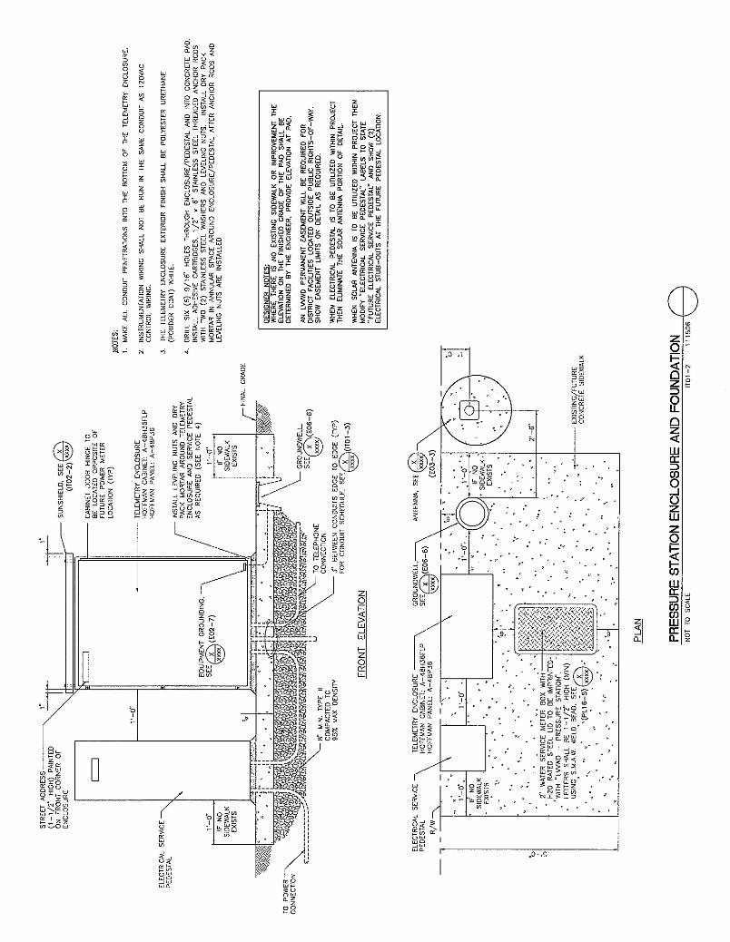
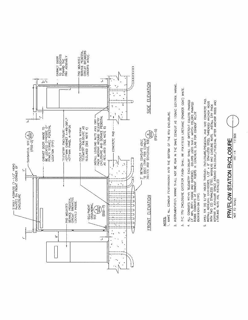
Pressure Station Assembly ............................................................... 11-15-06 IT01-1 Pressure Station Enclosure and Foundation ..................................... 11-15-06 IT01-2 Pressure Station Conduit Layout Diagram ...................................... 11-15-06 IT01-3 PRV/Flow Station Enclosure ........................................................... 11-15-06 IT01-4 PRV/Flow Station Conduit Layout Diagram ................................... 11-15-06 IT01-5 TELEMETRY ENCLOSURE DETAILS
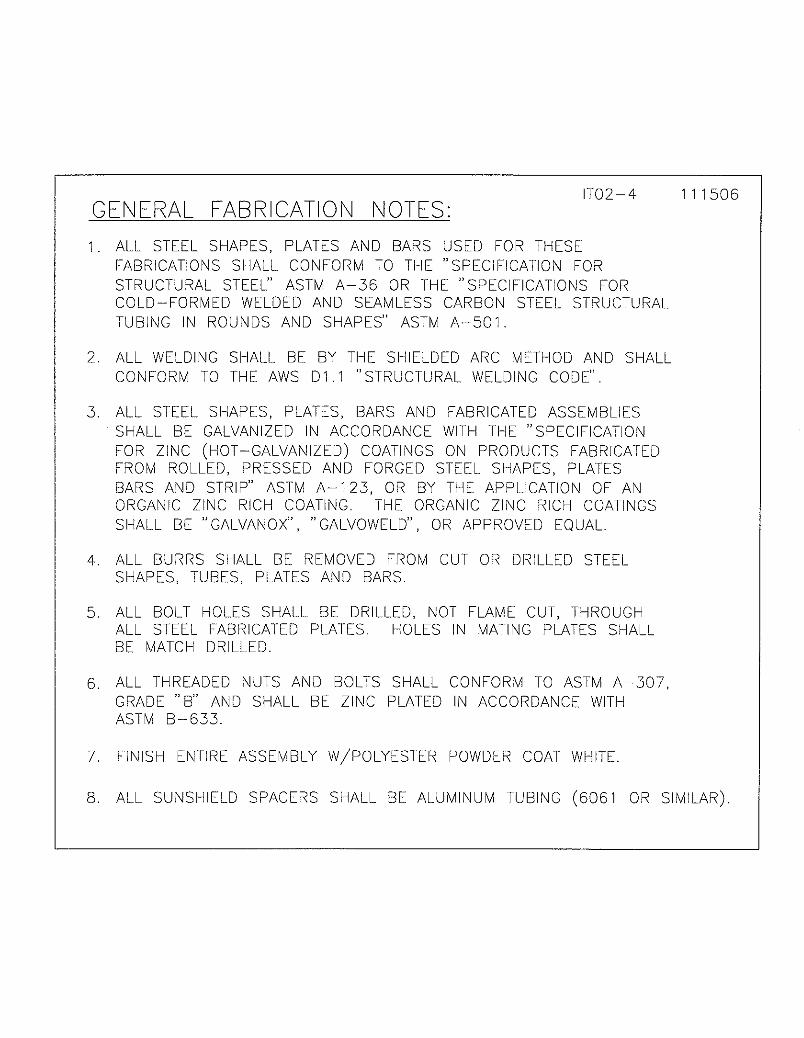
PRV/Flow Station Enclosure Bolt Hole Alignments (Top & Side) .. 11-15-06 IT02-1 PRV/Flow Station Enclosure Sunshield .......................................... 11-15-06 IT02-2 Enclosure Sunshield Mounting Spacers........................................... 11-15-06 IT02-3 General Fabrication Notes ............................................................... 11-15-06 IT02-4 PRV/Flow Station Enclosure Conduit and Battery Layout (Solar) .. 11-15-06 IT02-5 INSTRUMENTATION GENERAL DETAILS
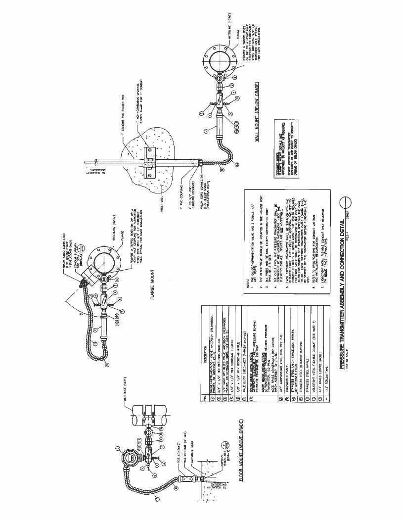
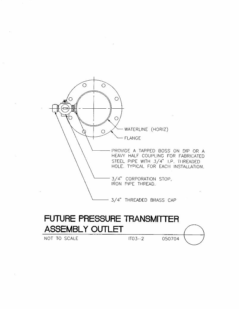
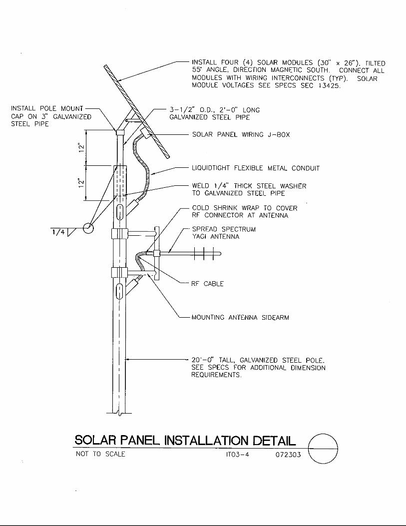
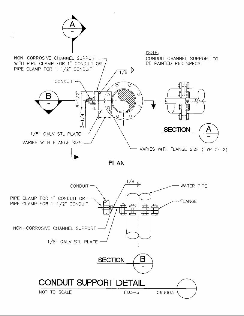
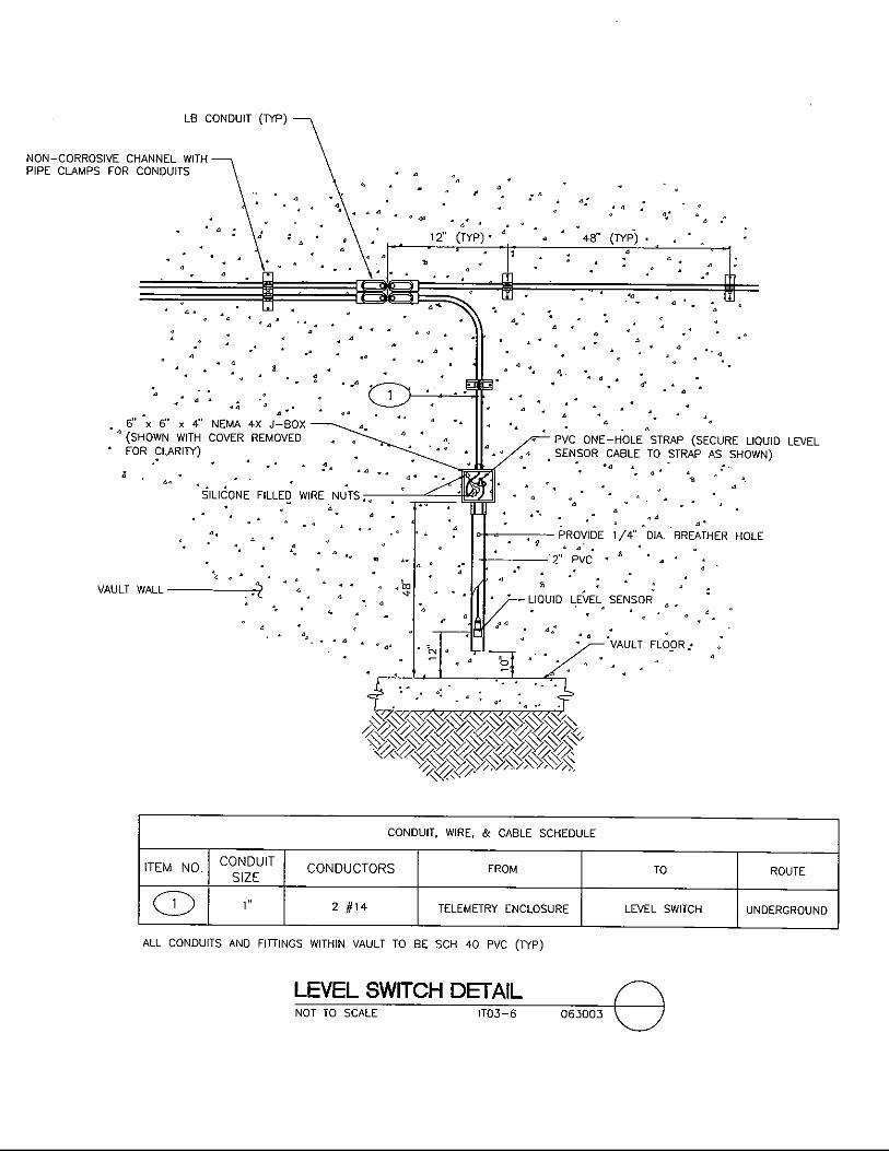
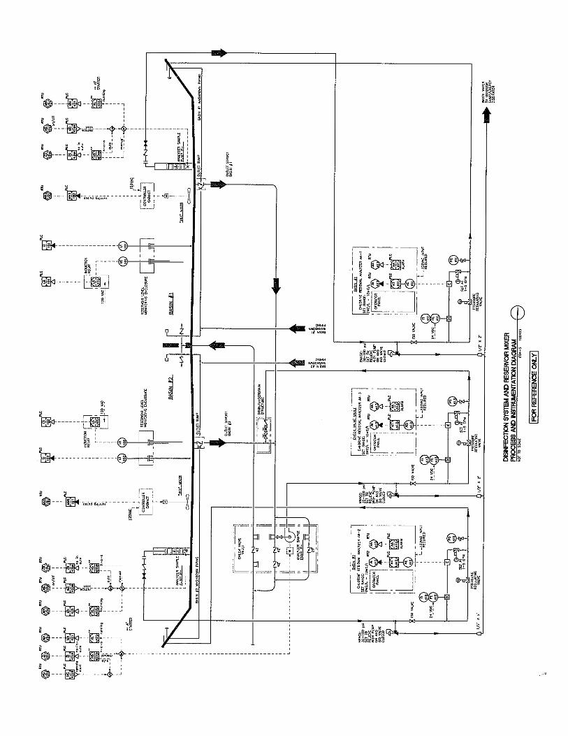
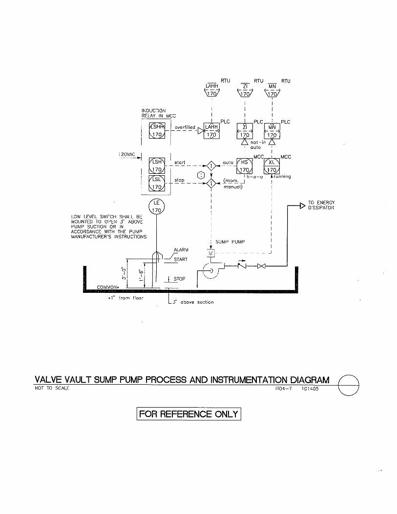
Pressure Transmitter Assembly and Connection Detail .................. 10-29-07 IT03-1 Future Pressure Transmitter Assembly Outlet ................................. 05-07-04 IT03-2 Antenna Detail ................................................................................. 06-23-10 IT03-3 Solar Panel Installation Detail ......................................................... 07-23-03 IT03-4 Conduit Support Detail .................................................................... 06-30-03 IT03-5 Level Switch Detail.......................................................................... 06-30-03 IT03-6 Pump Station “RTU” Enclosure Conduit Layout ............................ 06-30-03 IT03-7 Typical 4-20mA Transmitter and Remote Display .......................... 06-30-03 IT03-8 P & ID Legend and Abbreviations................................................... 04-19-07 IT04-1 PRV Process and Instrumentation Diagram .................................... 08-01-06 IT04-2 PRV and Solenoid Positioning Table .............................................. 08-01-06 IT04-2A Well Pump Process and Instrumentation Diagram .......................... 10-10-05 IT04-3 Booster Pump Process and Instrumentation Diagram ..................... 10-10-05 IT04-4 Disinfection System and Reservoir Mixer Process and Instrumentation Diagram .......................................................... 10-24-05 IT04-5 NAOCL Storage and Feed System Process and Instrumentation Diagram .......................................................... 04-19-07 IT04-6 Valve Vault Sump Pump Process and Instrumentation Diagram .... 10-14-05 IT04-7 Building and Site Systems Process and Instrumentation Diagram .. 10-17-05 IT04-8 Drain/Underdrain Structure Sump Pumps Process and Instrumentation Diagram .......................................................... 10-17-05 IT04-9 Elevator Sump Pump Process and Instrumentation Diagram .......... 10-19-05 IT04-10 Facility Air System Process and Instrumentation Diagram ............. 04-19-07 IT04-11

LAS VEGAS VALLEY WATER DISTRICT DESIGN DETAIL STANDARDS
TABLE OF CONTENTS
DESCRIPTION REV. DATE DWG NO.
Table of Contents ii Instrumentation
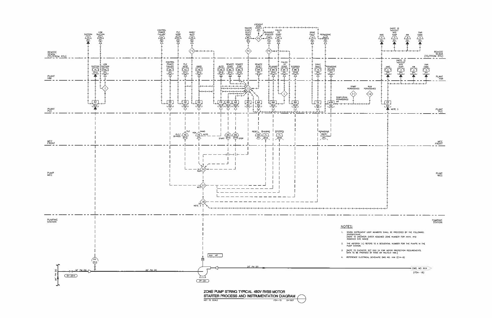
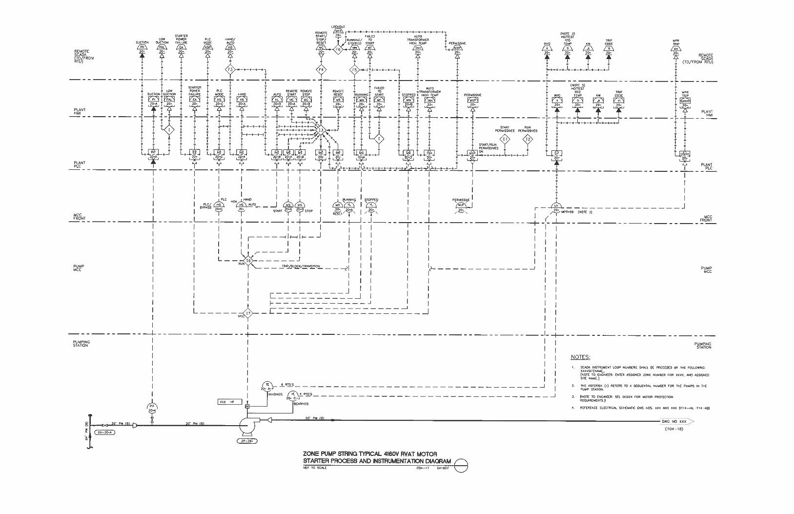
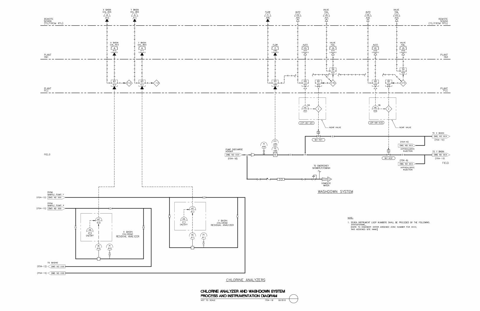
Zone Pump String Reservoir and Vault Process and Instrumentation Diagram .......................................................... 04-19-07 IT04-12 Zone Pump String Typical 480V FVNR Motor Starter Process and Instrumentation Diagram ............................................. 04-19-07 IT04-13 Zone Pump String Typical 480V VFD - Driven Motor Process and Instrumentation Diagram ............................................. 04-19-07 IT04-14 Zone Pump String Typical 480V RVSS Motor Starter Process and Instrumentation Diagram ............................................. 04-19-07 IT04-15 Zone Pump String Typical 4160V RVSS Motor Starter Process and Instrumentation Diagram ............................................. 04-19-07 IT04-16 Zone Pump String Typical 4160V RVAT Motor Starter Process and Instrumentation Diagram ............................................. 04-19-07 IT04-17 Zone Pump String Typical Discharge Control Valve Process and Instrumentation Diagram ............................................. 04-19-07 IT04-18 Chlorine Analyzer and Washdown System Process and Instrumentation Diagram ............................................. 06-15-10 IT04-19 Discharge Piping and Vault Process and Instrumentation Diagram ............................................. 04-17-07 IT04-20 Miscellaneous Systems Process and Instrumentation Diagram ....... 04-17-07 IT04-21 RTU & PLC LAYOUT AND DIAGRAM DETAILS
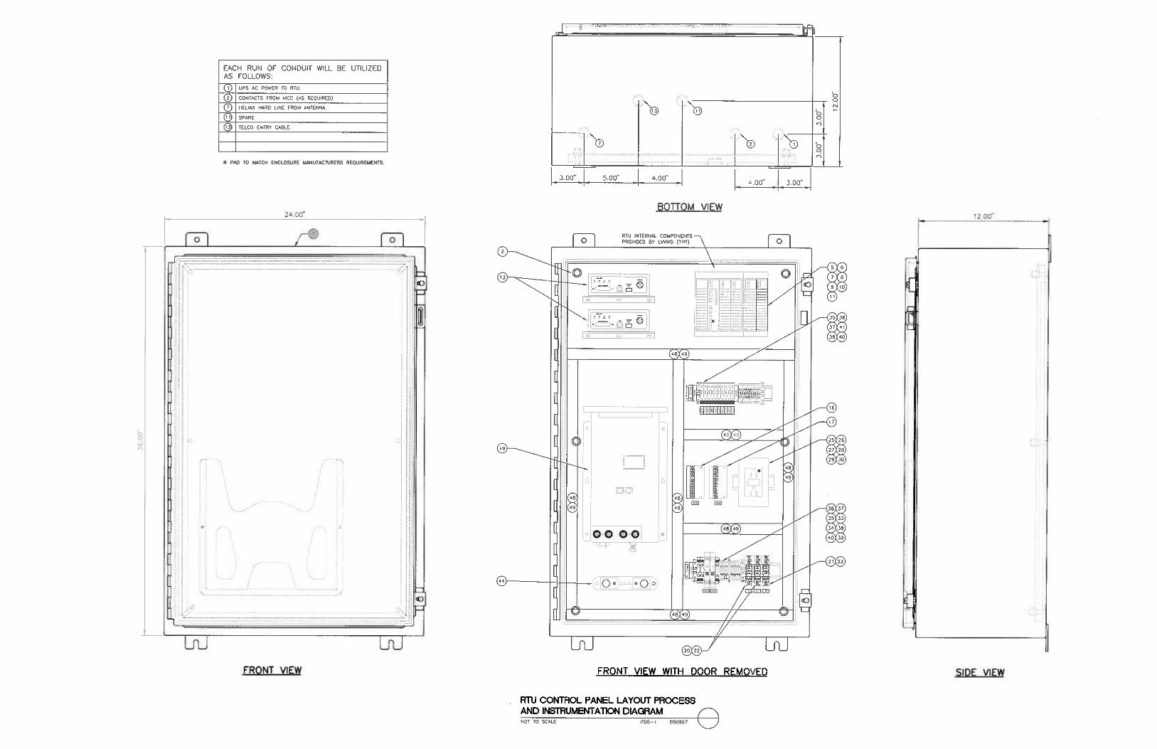
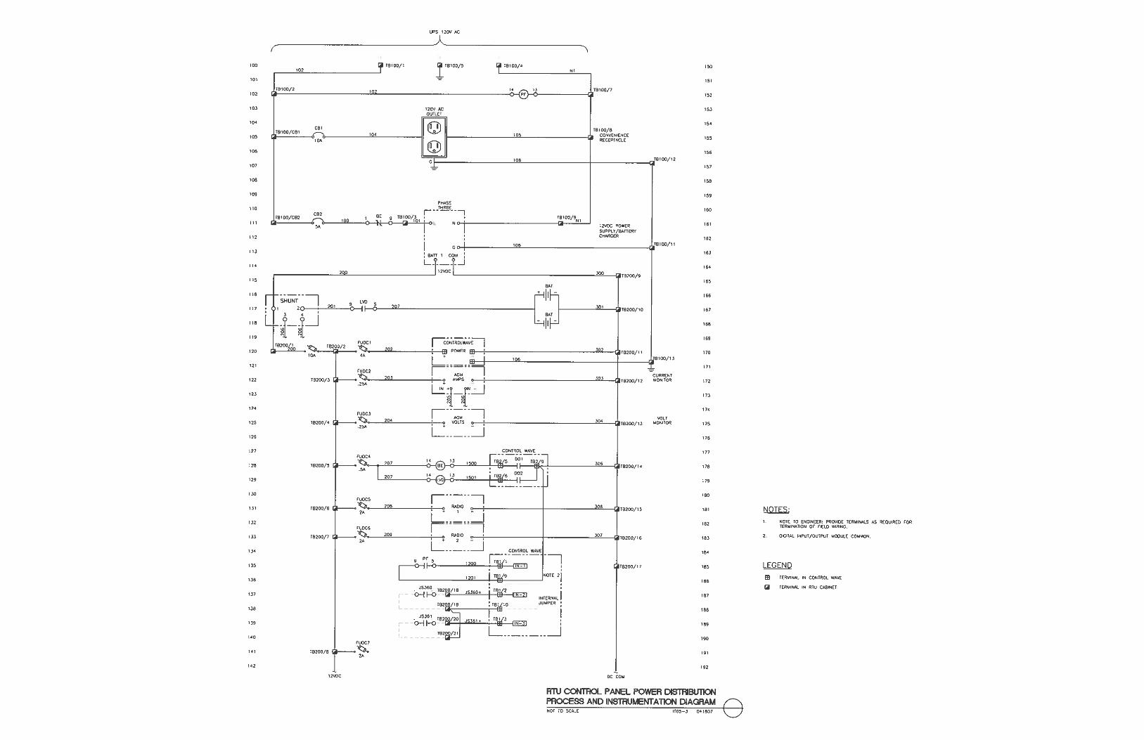
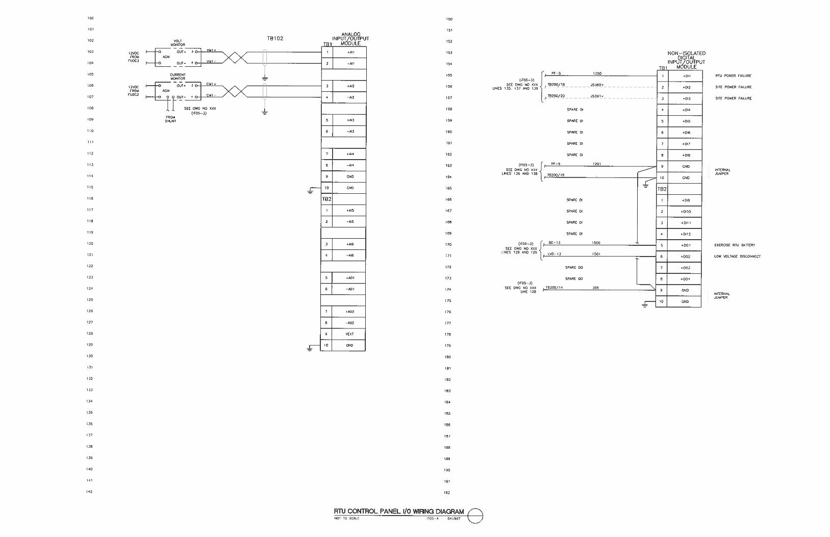
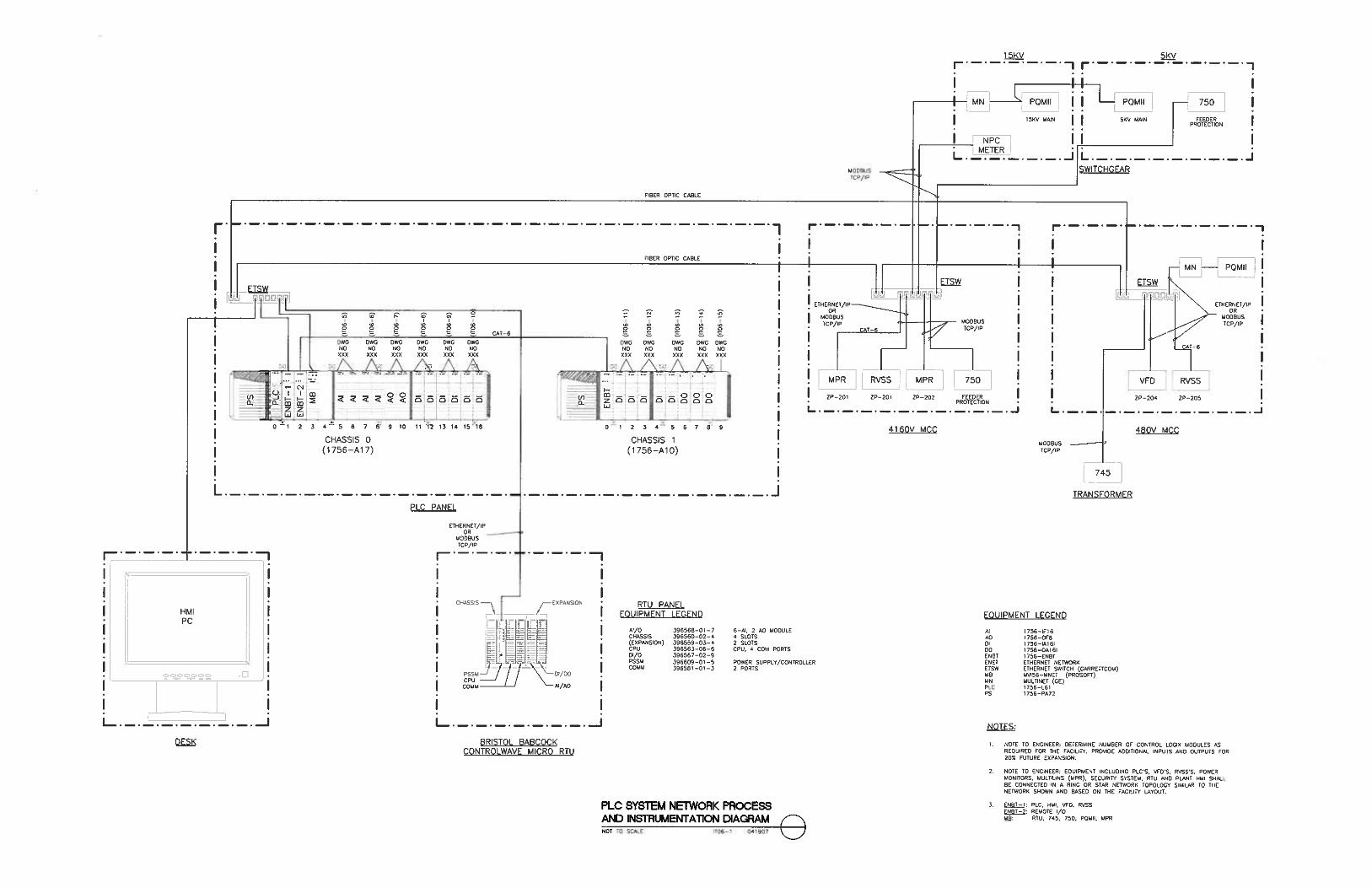
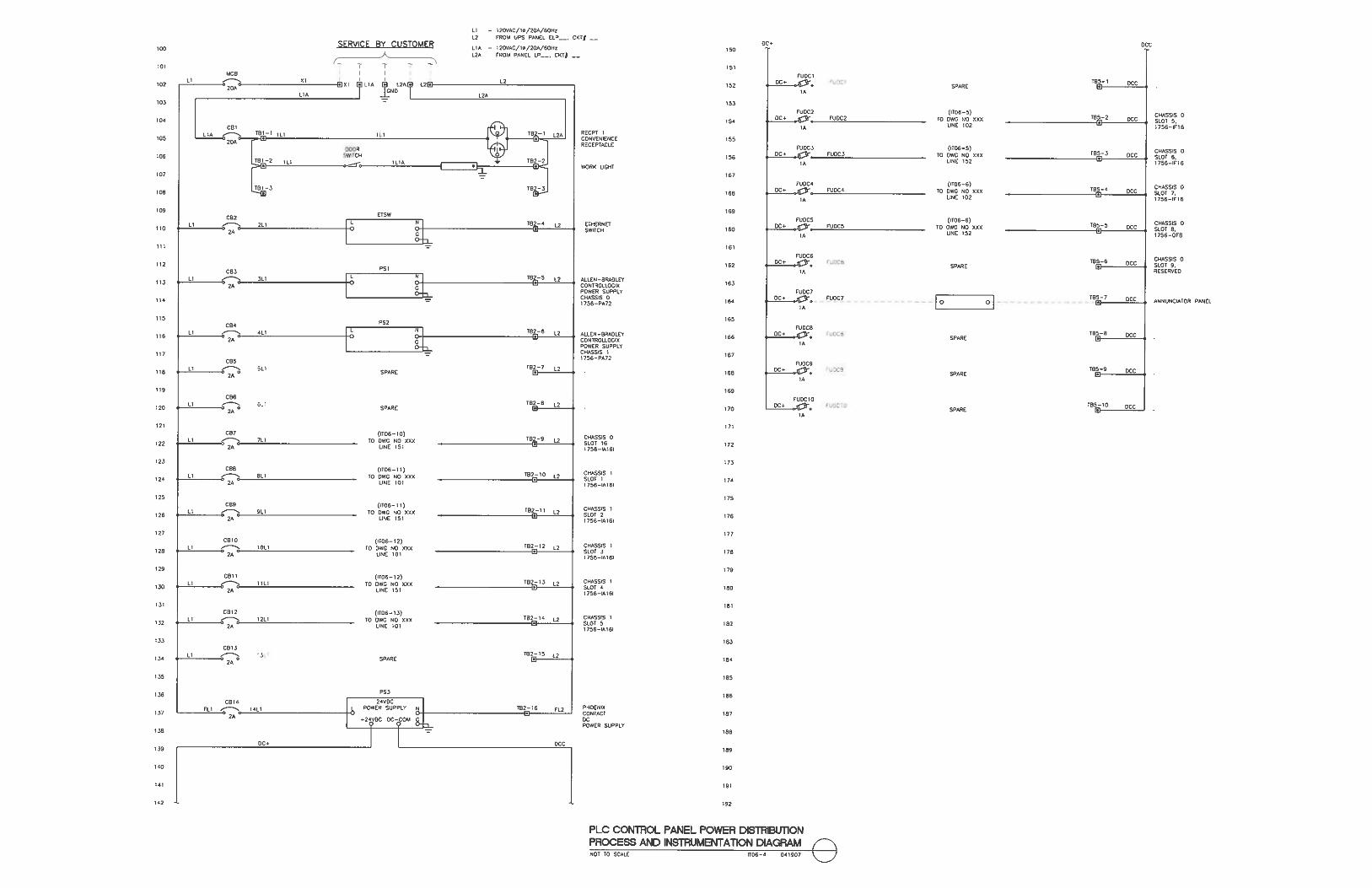
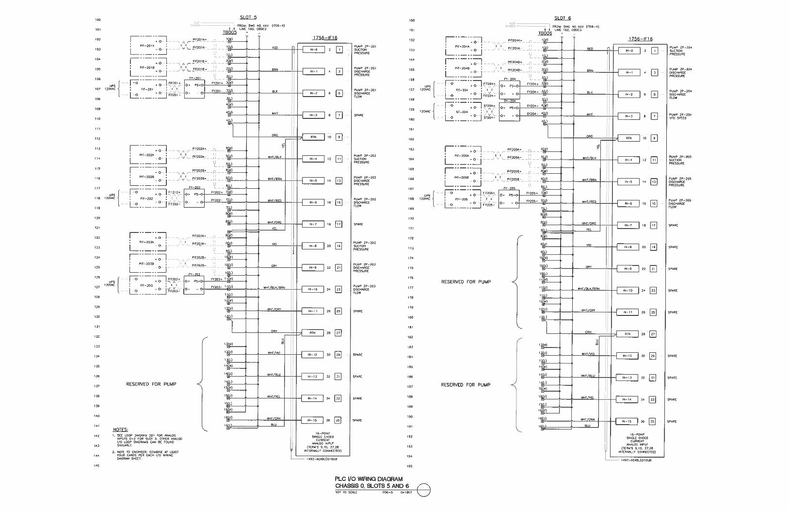
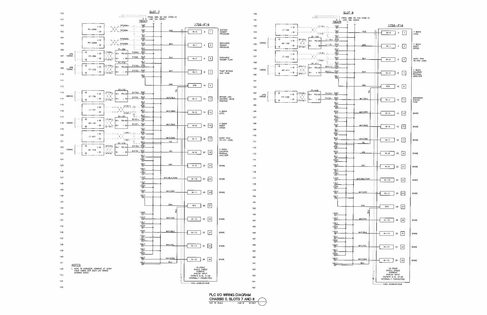
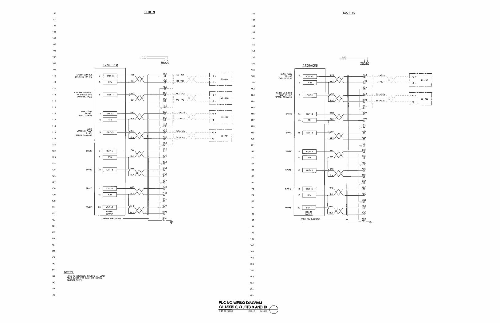
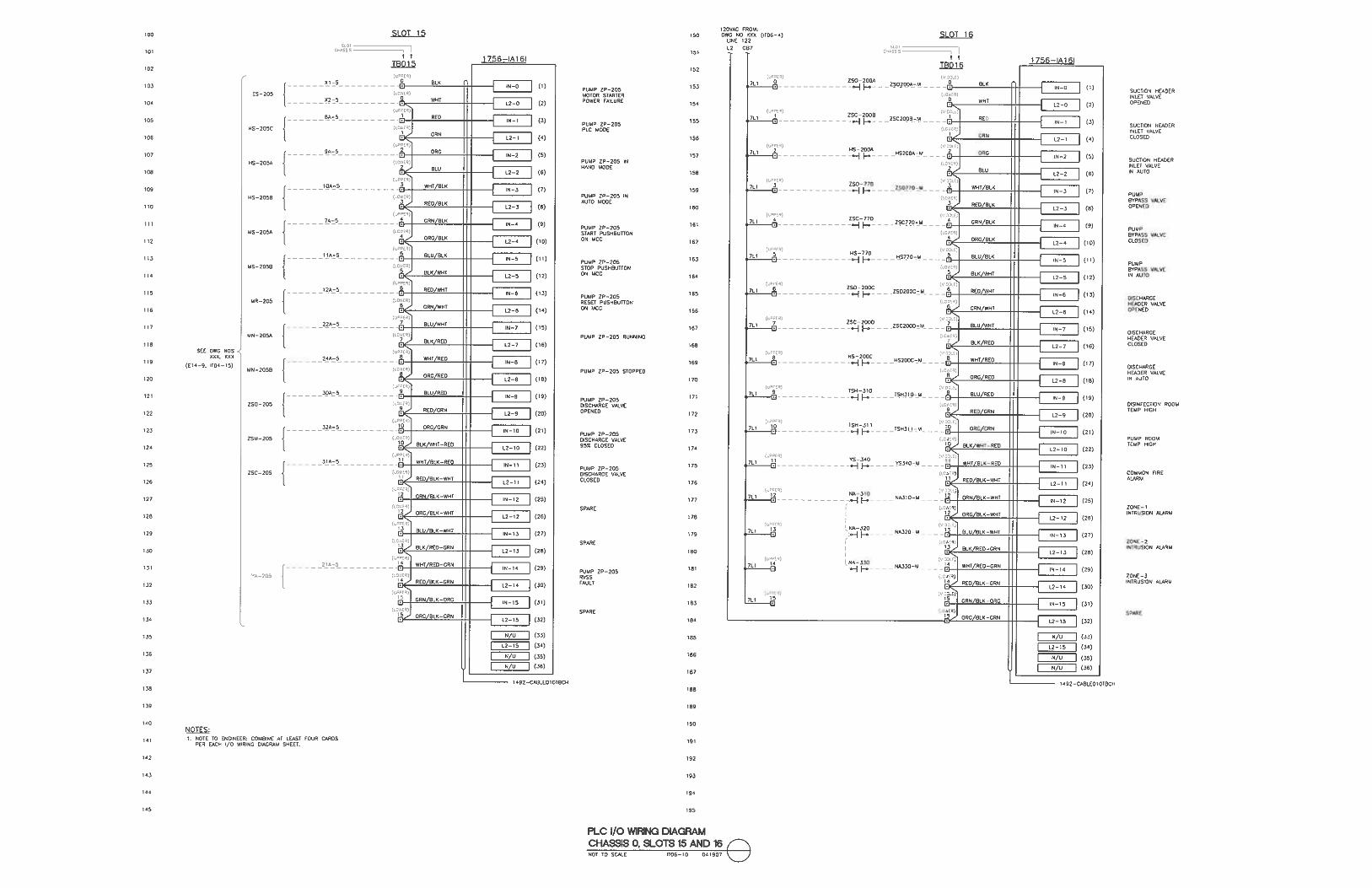
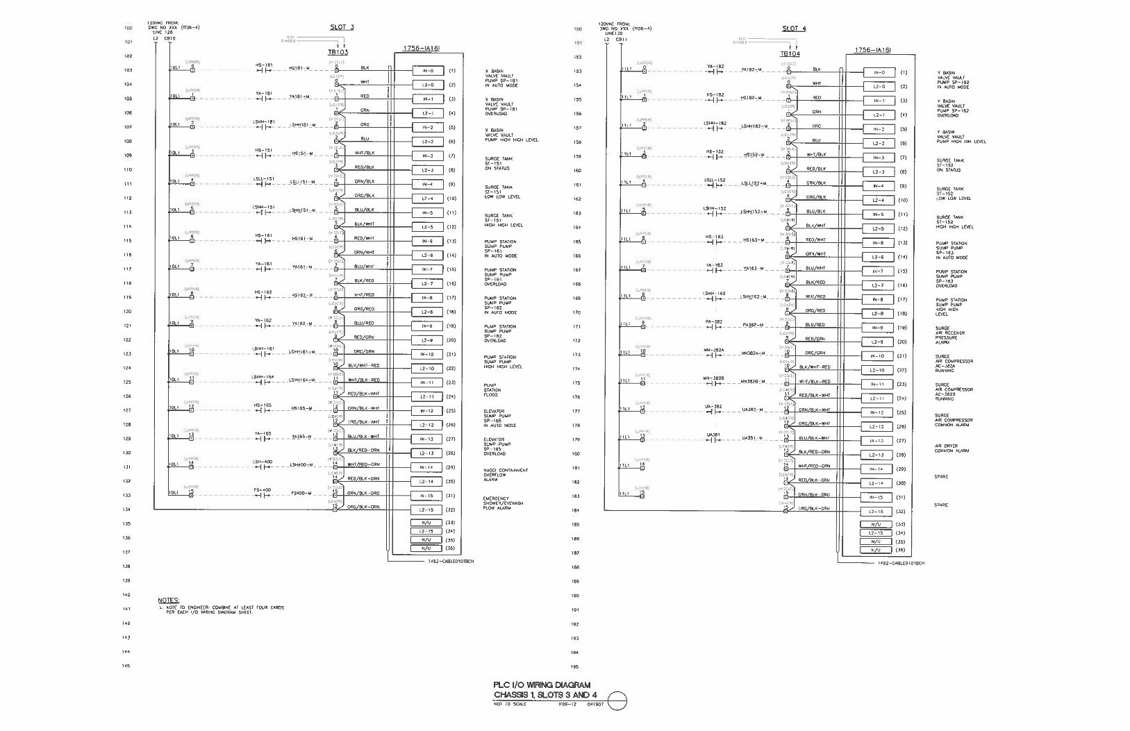
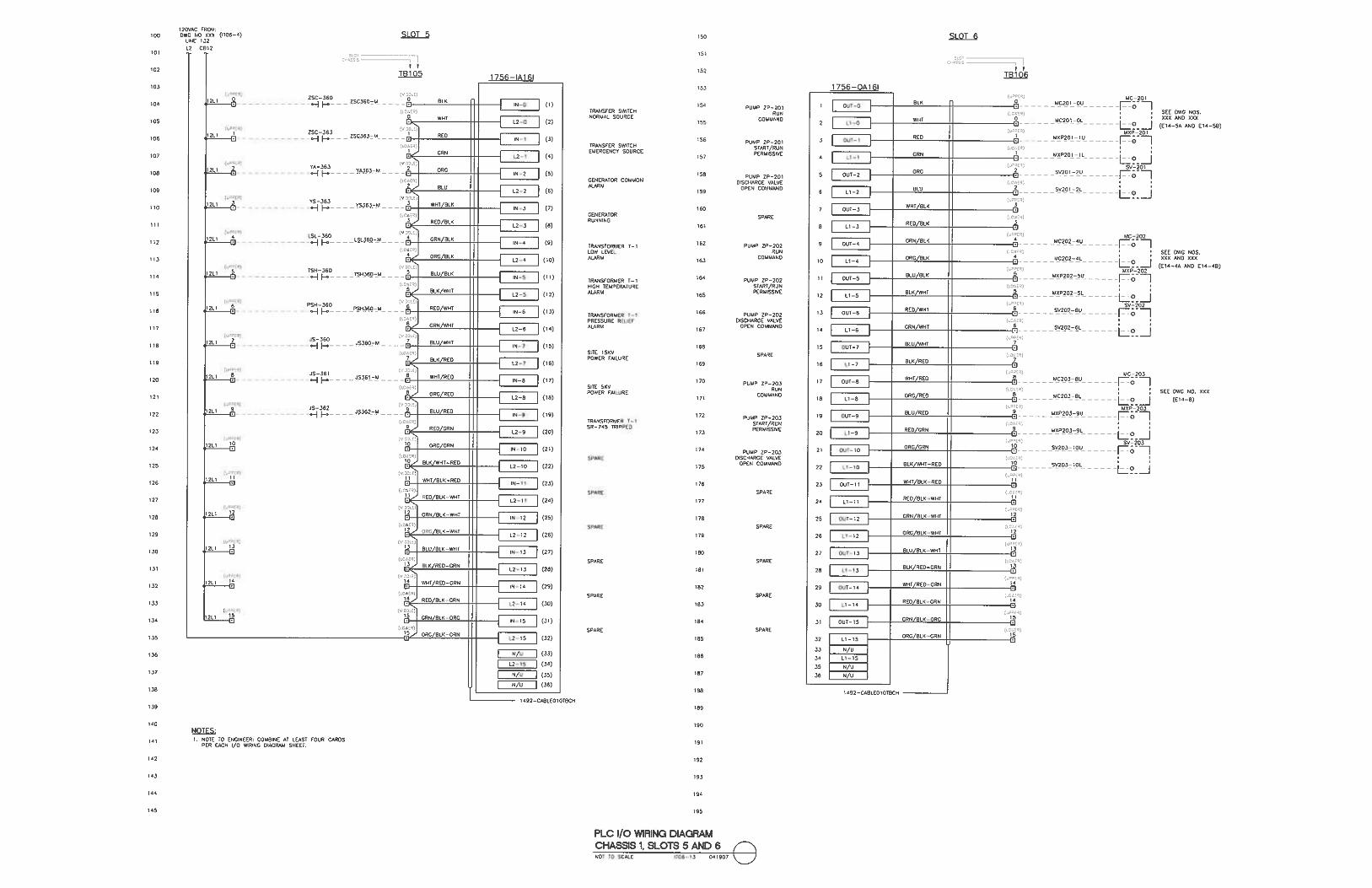
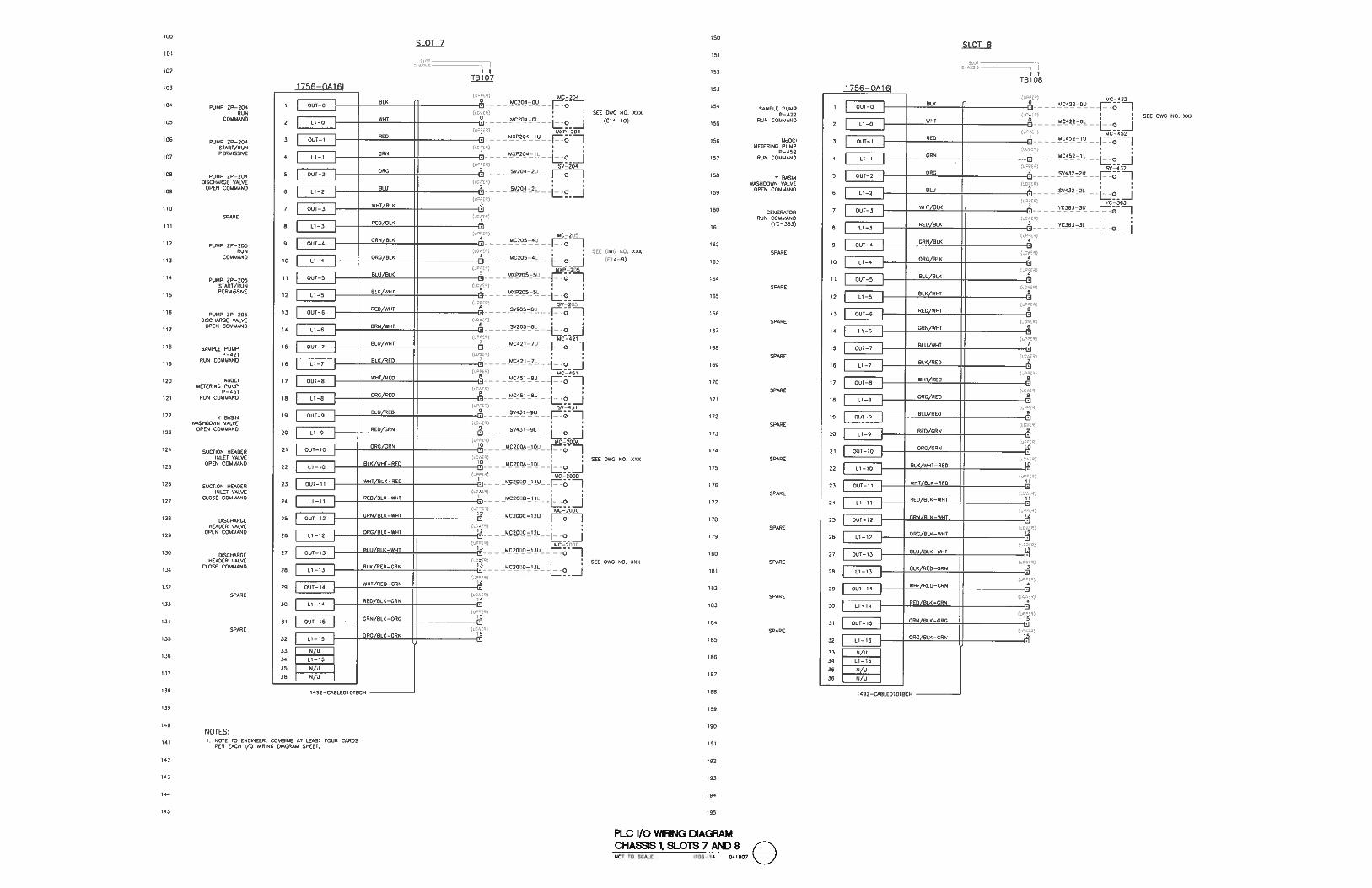
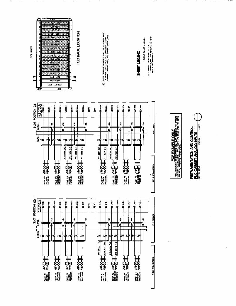
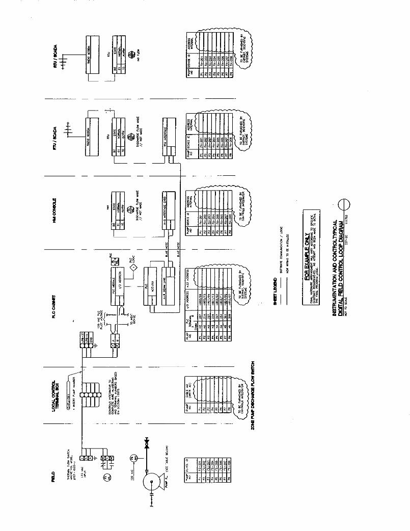
RTU Control Panel Layout Process and Instrumentation Diagram .......................................................... 05-08-07 IT05-1 RTU Control Panel Bill of Materials ............................................... 04-18-07 IT05-2 RTU Control Panel Power Distribution Process and Instrumentation Diagram .......................................................... 04-18-07 IT05-3 RTU Control Panel I/O Wiring Diagram ......................................... 04-19-07 IT05-4 PLC System Network Process and Instrumentation Diagram ......... 04-19-07 IT06-1 PLC Control Panel Layout ............................................................... 04-18-07 IT06-2 PLC Control Panel Bill of Materials ................................................ 04-18-07 IT06-3 PLC Control Panel Power Distribution Process and Instrumentation Diagram .......................................................... 04-19-07 IT06-4 PLC I/O Wiring Diagram Chassis 0, Slots 5 and 6.......................... 04-19-07 IT06-5 PLC I/O Wiring Diagram Chassis 0, Slots 7 and 8.......................... 04-19-07 IT06-6 PLC I/O Wiring Diagram Chassis 0, Slots 9 and 10........................ 04-19-07 IT06-7 PLC I/O Wiring Diagram Chassis 0, Slots 11 and 12...................... 04-19-07 IT06-8 PLC I/O Wiring Diagram Chassis 0, Slots 13 and 14...................... 04-19-07 IT06-9 PLC I/O Wiring Diagram Chassis 0, Slots 15 and 16...................... 04-19-07 IT06-10 PLC I/O Wiring Diagram Chassis 1, Slots 1 and 2.......................... 04-19-07 IT06-11 PLC I/O Wiring Diagram Chassis 1, Slots 3 and 4.......................... 04-19-07 IT06-12