LVN5200A-R2, rev. 1, Hardware Installation...
12
LVN5200A-R2, rev. 1, Hardware Installation Guide LVN5200A-R2 LVN5250A-R2 Order toll-free in the U.S.: Call 877-877-BBOX (outside U.S. call 724-746-5500) FREE technical support 24 hours a day, 7 days a week: Call 724-746-5500 or fax 724-746-0746 Mailing address: Black Box Corporation, 1000 Park Drive, Lawrence, PA 15055-1018 Web site: www.blackbox.com Email: [email protected] Customer Support Information
-
Upload
phungkhanh -
Category
Documents
-
view
220 -
download
2
Transcript of LVN5200A-R2, rev. 1, Hardware Installation...

LVN5200A-R2, rev. 1, Hardware Installation Guide
LVN5200A-R2LVN5250A-R2
Order toll-free in the U.S.: Call 877-877-BBOX (outside U.S. call 724-746-5500)FREE technical support 24 hours a day, 7 days a week: Call 724-746-5500 or fax 724-746-0746Mailing address: Black Box Corporation, 1000 Park Drive, Lawrence, PA 15055-1018Web site: www.blackbox.com Email: [email protected]
CustomerSupport
Information

LVN5200A-R2, rev. 1, Hardware Installation Guide
Page 2 724-746-5500 blackbox.com
Section 1 Safety Notice and Warnings . . . . . . . . . . . . . . . . . . . . . . . . . . . . . . . . . . . . . . . . . . . . . . . . . . 3
Section 2 Ratings . . . . . . . . . . . . . . . . . . . . . . . . . . . . . . . . . . . . . . . . . . . . . . . . . . . . . . . . . . . . . . . . . . 3
Section 3 Electrical and General Safety Guidelines . . . . . . . . . . . . . . . . . . . . . . . . . . . . . . . . . . . . . . . . . 4
Section 4 Site Preparation . . . . . . . . . . . . . . . . . . . . . . . . . . . . . . . . . . . . . . . . . . . . . . . . . . . . . . . . . . . 6
Section 5 Unpacking the Appliance . . . . . . . . . . . . . . . . . . . . . . . . . . . . . . . . . . . . . . . . . . . . . . . . . . . . 7
Section 6A Installing the Appliance in a 4-Post Rack . . . . . . . . . . . . . . . . . . . . . . . . . . . . . . . . . . . . . . . . 8
Section 6B Installing the Appliance in a 2-Post Rack . . . . . . . . . . . . . . . . . . . . . . . . . . . . . . . . . . . . . . . . 9
Section 7 Rear Panel Connections . . . . . . . . . . . . . . . . . . . . . . . . . . . . . . . . . . . . . . . . . . . . . . . . . . . . . 10
Section 8 Front Panel Operation . . . . . . . . . . . . . . . . . . . . . . . . . . . . . . . . . . . . . . . . . . . . . . . . . . . . . . 11
Table of Contents

LVN5200A-R2, rev. 1, Hardware Installation Guide
724-746-5500 blackbox.com
1. Safety Notice and Warnings
2. Ratings
FCC NoticeThis device complies with part 15 of the FCC Rules. Operation is subject to the following two conditions:
1. This device may not cause harmful interference.
2. This device must accept any interference received, including interference that may cause undesired operation.
No Telecommunications Network Voltage (TNV)-connected PCBs shall be installed.
This class A digital apparatus complies with Canadian ICES-003.Cet appareil numérique de la classe A est conforme à la norme NMB-003 du Canada.
CE Mark WarningThis is a Class A product. In a domestic environment, this product may cause radio interference, in which case the user may be required to take adequate measures.
VCCI WarningThis is a product of VCCI Class A Compliance.
Environmental WarningPerchlorate Material - special handling may apply. See www.dtsc.ca.gov/hazardouswaste/perchlorate.
This notice is required by California Code of Regulations, Title 22, Division 4.5, Chapter 33: Best Management Practices for Perchlorate Materials. This product/part includes a battery that contains Perchlorate material.
AC input voltage: 100 - 240 VAC (auto-range)
Hz: 50/60
Rated input current: 4 Amps Max
Page 3

LVN5200A-R2, rev. 1, Hardware Installation Guide
Page 4 724-746-5500 blackbox.com
3. Electrical and General Safety Guidelines
CAUTIONThis appliance is intended for installation in restricted areas only. Initial setup and maintenance should be performed by qualified personnel.
CAUTIONPower down the appliance following the operating system’s proper power down procedure from the front panel. Unplug all AC power cord(s) before servicing.
CAUTIONTo avoid electrical shock, check the power cords as follows:
• This product is to be installed in Restricted Access Location only.
• Use the exact type of power cords required.
• Use power cord(s) that came with safety certifications.
• Power cord(s) must comply with AC voltage requirements in your region.
• The power cord plug cap must have an electrical current rating that is at least 125% of the electrical current rating of this product.
• The power cord plug cap that plugs into the AC receptacle on the power supply must be a type female connector.
• Plug the power cord(s) into a socket that is properly grounded before turning on the power.
CAUTIONRequired operating conditions for the appliance are -
• Temperature: 10 to 35oC.
• Humidity, non-condensing: 8 to 90%.
CAUTIONRisk of explosion if the battery is installed upside down or is replaced by an incorrect type. Dispose of used batteries according to the instructions.
DISPOSING OF BATTERY BACKUP UNITS - IF APPLICABLEWARNINGIf the BBU is damaged in any way, toxic chemicals may be released.
The material in the battery pack contains heavy metals that can contaminate the environment. Federal, state, and local regulations prohibit the disposal of rechargeable batteries in public landfills. Be sure to recycle the old battery packs properly. Comply with all applicable battery disposal and hazardous material handling laws and regulations in the country or other jurisdiction where you areusing the BBU.
WARNINGThere is danger of an explosion if the battery is incorrectly replaced. Replace it only with the same or equivalent type recommended by the manufacturer. Dispose of used batteries according to the manufacturer’s instructions.
LVN5200A-R2, rev. 1, Hardware Installation Guide
Page 5724-746-5500 blackbox.com
3. Electrical and General Safety Guidelines (continued)
WARNINGDisconnect the power supply at the circuit breaker before accessing any components. Turning off the system power supply switch does not reduce the risk of electrical shock from the power supply terminal block.
CAUTION• To prevent the unit from overheating, never install the appliance in an enclosed area that is
not properly ventilated or cooled. For proper airflow, keep the front and back sides of the appliance clear of obstructions and away from the exhaust of other equipment.
• Be aware of the locations of the power switches on the chassis and in the room, so you can disconnect the power supply if an accident occurs.
• Take extra precautionary measures when working with high voltage components. Do not work alone.
• Before removing or installing main system components, be sure to disconnect the power first. Turn off the system before you disconnect the power supply.
• Use only one hand when working with powered-on electrical equipment to avoid possible electrical shock.
• Use rubber mats specifically designed as electrical insulators when working with computer systems.
• The power supply or power cord must include a grounding plug and must be plugged into grounded outlets.
CAUTIONElectric Static Discharge (ESD) can damage electronic components. To prevent damage to your system board, it is important to handle it very carefully. The following measures can prevent ESDdamage to critical components.
• Use a grounded wrist strap designed to prevent static discharge.
• Keep all components and printed circuit boards (PCBs) in their antistatic bags until ready for use.
• Touch a grounded metal object before removing the board from the antistatic bag.
• Do not let components or PCBs come into contact with your clothing, which may retain a charge even if you are wearing a wrist strap.
• Handle a board by its edges only; do not touch its components, peripheral chips, memory modules or contacts.
• When handling chips or modules, avoid touching their pins.
• Put the motherboard and peripherals back into their antistatic bags when not in use.
• For grounding purposes, make sure your computer chassis provides excellent conductivity between the power supply, the case, the mounting fasteners and the motherboard.

LVN5200A-R2, rev. 1, Hardware Installation Guide
Page 6 724-746-5500 blackbox.com
Setup location, rack and appliance precautions• Elevated Operating Ambient - If installed in a closed or multi-unit rack assembly, the operating ambient
temperature of the rack environment may be greater than room ambient. Therefore, consideration should be given to installing the equipment in an environment compatible with the maximum ambient temperature (Tma) specified by the manufacturer.
Always keep the rack’s front door and all panels and components on the appliances closed when not servicing to maintain proper cooling.
• Reduced Air Flow - Installation of the equipment in a rack should be such that the amount of air flow required for safe operation of the equipment is not compromised. Leave enough clearance, approximately 25 inches in the front, and 30 inches in the back of the rack to enable you to access appliance components and allow for sufficient air flow.
• Mechanical Loading - Mounting of the equipment in the rack should be such that a hazardous condition is not achieved due to uneven mechanical loading.
ALL RACKS MUST BE MOUNTED SECURELY. Ensure that all leveling jacks or stabilizers are properly attached to the rack. If installing multiple appliances in a rack, make sure the overall loading for each branch circuit does not exceed the rated capacity.
Do not slide more than one appliance out from the rack at a time. Extending more than one appliance at a time may result in the rack becoming unstable. Install your appliance in the lower part of the rack because of its weight and also for ease in accessing appliance components.
• Circuit Overloading - Consideration should be given to the connection of the equipment to the supply circuit and the effect that overloading of the circuits might have on overcurrent protection and supply wiring. Appropriate consideration of equipment nameplate ratings should be used when addressing this concern.
• Reliable Earthing - Reliable earthing of rack-mounted equipment should be maintained. Particular attention should be given to supply connections other than direct connections to the branch circuit (e.g. use of power strips).
Install near appropriate AC outlets, and Ethernet hubs or individual jacks. Be sure to install an AC Power Disconnect for the entire rack assembly. The Power Disconnect must be clearly marked. Ground the rack assembly properly to avoid electrical shock.
4. Site Preparation
LVN5200A-R2, rev. 1, Hardware Installation Guide
Page 7724-746-5500 blackbox.com
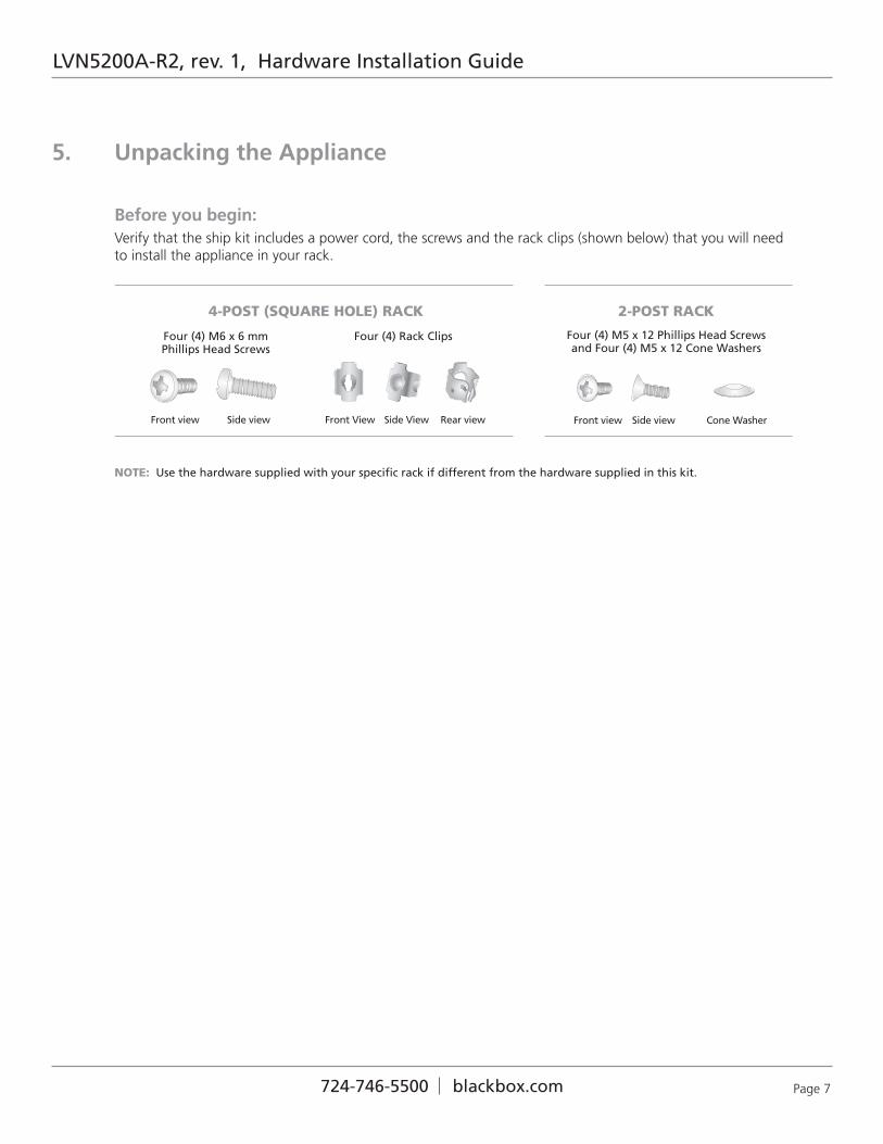
Before you begin:Verify that the ship kit includes a power cord, the screws and the rack clips (shown below) that you will need to install the appliance in your rack.
Front view Side view Front View Side View Rear view
NOTE: Use the hardware supplied with your specific rack if different from the hardware supplied in this kit.
Four (4) M6 x 6 mm Phillips Head Screws
4-POST (SQUARE HOLE) RACK
Front view Side view Cone Washer
2-POST RACK
Four (4) M5 x 12 Phillips Head Screwsand Four (4) M5 x 12 Cone Washers
Four (4) Rack Clips
5. Unpacking the Appliance

Install tworack clips inthe top andbottom ofthree holes
Leavemiddle holeempty
4-Post Rack
LVN5200A-R2, rev. 1, Hardware Installation Guide
Page 8 724-746-5500 blackbox.com
6A. Installing the Appliance in a 4-Post Rack
Step 1• Install two rack clips into the top and
bottom of three holes on each side in the rack as shown. The tabs on each should be on the top and bottom to help stabilize them in the holes. No tools are needed to install the clips, firmly press them into place
• Make sure the clips are level in height on the left and right sides for proper alignment to allow accurate appliance installation.
Step 2• Install the appliance in the rack
as shown by inserting one M6 x 16 screw* through the top and bottom holes in the ears on each side into the rack clips on each side.
• Tighten each screw to secure the appliance in the rack.
4-Post Rack
Two (2) M5 x 12 flat head screwsand two cone washers on each side
*
NOTE: When installing (or removing) the appliance from the rack make sure to support the unit at all times.
NOTE: Refer to your rack’s mounting hardware for the proper size and type of screws to secure the appliance in the rack.
*
LVN5200A-R2, rev. 1, Hardware Installation Guide
Page 9724-746-5500 blackbox.com
6B. Installing the Appliance in a 2-Post Rack
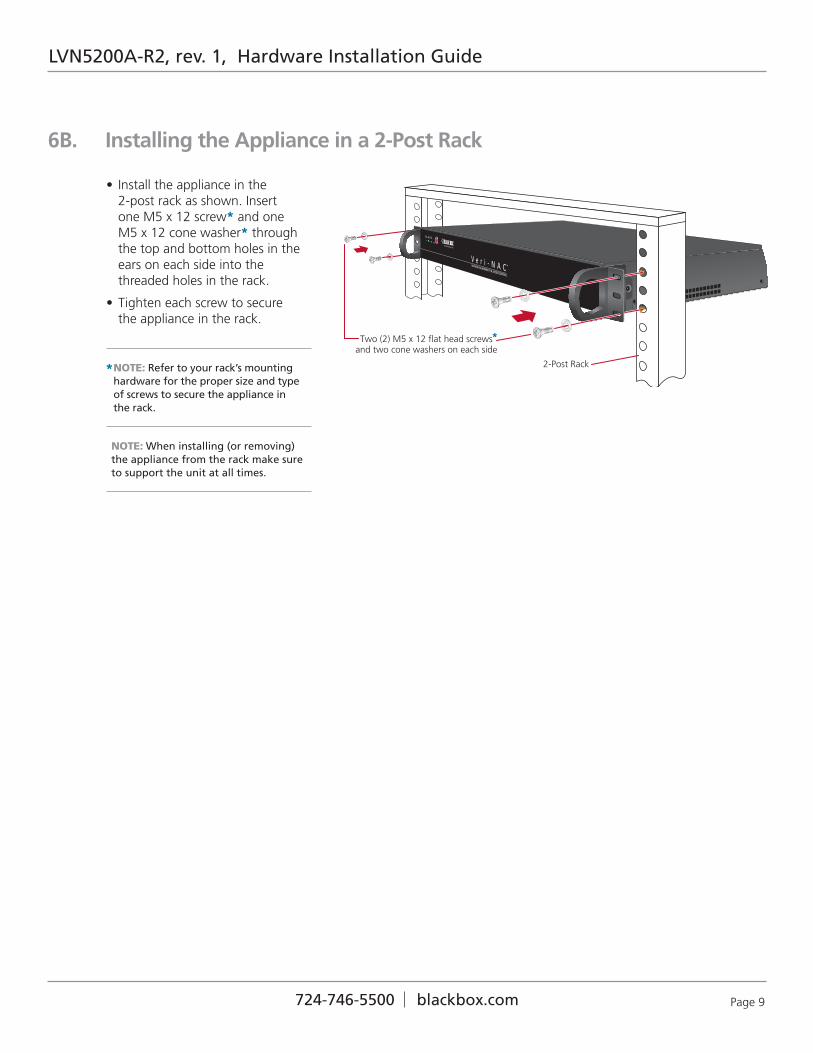
• Install the appliance in the 2-post rack as shown. Insert one M5 x 12 screw* and one M5 x 12 cone washer* through the top and bottom holes in the ears on each side into the threaded holes in the rack.
• Tighten each screw to secure the appliance in the rack.
2-Post Rack
Two (2) M5 x 12 flat head screwsand two cone washers on each side
*
NOTE: When installing (or removing) the appliance from the rack make sure to support the unit at all times.
NOTE: Refer to your rack’s mounting hardware for the proper size and type of screws to secure the appliance in the rack.
*

LVN5200A-R2, rev. 1, Hardware Installation Guide
Page 10 724-746-5500 blackbox.com
7. Rear Panel Connections
Ethernet Cables
PCI expansion slot
Power SupplyFan
AC Power Inlet
Mouse Port
Network Interface Connectors
VGA Port
Serial Port
USB Ports
Power Cord
Keyboard Port
2
1
Eth1Eth0
Step 1: Connect the power cord.
Step 2: Connect the Ethernet cables.
Step 3: Connect any other required cables.
Proceed to Front Panel Operation on page 11.

LVN5200A-R2, rev. 1, Hardware Installation Guide
Page 11724-746-5500 blackbox.com
• Power on the appliance using the Power Button on the front panel. The I/O Power Button is the last button on the right when looking at the front of the appliance.
Reset Button
I/O Power Button
8. Front Panel Operation

Black Box Tech Support: FREE! Live. 24/7
Tech support theway it should be.
Great tech support is just 30 seconds away at 724-746-5500 or blackbox.com.
About Black Box
Black Box Network Services is your source for more than 118,000networking and infrasctructure products. You’ll find everythingfrom cabinets and racks and power and surge protection productsto media converters and Ethernet switches all supported by free,live 24/7 Tech support available in 30 seconds or less.
© Copyright 2010. All rights reserved.
LVN5200A-R2, rev. 1
724-746-5500 blackbox.com