
LVC Architecture Roadmap (LVCAR) Implementation Project Workshop Gateways Performance Benchmarks...
99
LVC Architecture Roadmap (LVCAR) Implementation Project Workshop Gateways Performance Benchmarks Prepared by: Robert R. Lutz, JHU/APL David L. Drake, JHU/APL Dannie Cutts, AEgis Technologies Group Michael J. O’Connor, Trideum Corporation Kurt Lessmann, Trideum Corporation
-
Upload
reilly-brecher -
Category
Documents
-
view
232 -
download
0
Transcript of LVC Architecture Roadmap (LVCAR) Implementation Project Workshop Gateways Performance Benchmarks...
LVC Architecture Roadmap (LVCAR) Implementation Project
Workshop
Gateways Performance Benchmarks
Prepared by:Robert R. Lutz, JHU/APLDavid L. Drake, JHU/APLDannie Cutts, AEgis Technologies GroupMichael J. O’Connor, Trideum CorporationKurt Lessmann, Trideum CorporationJim Chase, Trideum Corporation

Gateways Performance Benchmarks: Workshop Agenda
Introductory Session Purpose of Workshop Overview of Bridges & Gateways Effort Need for Performance Benchmarks Overview of Performance Benchmark Elements Description of Performance Benchmark Elements
Breakout Sessions Gateway Developers Gateway Users
Results Summary and Feedback
2
3
Purpose of Workshop
Educate Gateway Developers and Users on the Gateway Performance Benchmark
Collect Feedback for the community to drive improvement to the Benchmark
Expectations
• Attendees requested to provide “first-thought” feedback during the workshop for immediate data collection. This will be collected before the breakout sessions
• Attendees requested to fill in and return off-site feedback form to provide additional feedback regarding more strategic topics
Follow-on Workshop tentatively planned August 2013
• Revised Benchmark will be reviewed for community feedback
4
Overview of Bridges & Gateways Effort:LVC Interoperability Challenges
Multi-architecture LVC environments are commonplace in support of DoD distributed test and training events
There are numerous difficult technical issues that must be addressed when integrating simulations across different simulation architectures
• Middleware incompatibilities
• Dissimilar development processes
• Dissimilar metamodels for runtime data exchange
Solutions to these issues can be extremely resource intensive to implement and inadequate testing can adversely affect the quality of the simulation results
There is a need to improve the quality and reduce the time and costs associated with the development of multi-architecture LVC environments
• Original motivation for the Live-Virtual-Constructive Architecture Roadmap (LVCAR) effort
Overview of Bridges & Gateways Effort:Live-Virtual-Constructive Architecture Roadmap (LVCAR) The Live-Virtual-Constructive Architecture Roadmap (LVCAR) was
established in the spring of 2007, continuing for approximately sixteen months • Intended to examine the differences among the major simulation
architectures from a technical, business, and standards perspective, and to develop a time-phased set of actions to improve interoperability within multi-architecture simulation environments in the future
• Resulted in a final report and supporting documentation that collectively totaled over a thousand pages
The implementation of LVCAR (LVCAR-I) recommendations began in the spring of 2009
• The LVCAR-I effort features a Gateway and Bridges project to develop processes, specifications and tools to make the selection and use of gateways more efficient
• As part of the Gateway and Bridges project, a Gateway Performance Benchmark was identified as being required by the community to aide in gateway selection
5
This workshop focuses on improving Gateway Performance Benchmark
6
Overview of Bridges & Gateways Effort:Gateways Background
Simulation is a critical enabler for system acquisition programs, and provides vital capabilities for such functional disciplines as analysis, test, and training
The advent of modern networking technology and the development of supporting protocols and architectures has led to widespread use of distributed simulation
To allow distributed simulations to be developed and integrated, communication infrastructures have been developed, and are referred to as simulation architectures
For the execution of large simulation exercises, the interconnection of multiple simulation architectures is often required, and to address the differences in communication protocols and Simulation Data Exchange Models (SDEMs), distributed simulation gateways are used
Gateways provide the most widely used means of facilitating interoperability within multi-architecture simulation environments
Overview of Bridges & Gateways Effort:Gateway Challenges Despite the many documented success stories associated with the use of gateways to
facilitate LVC interoperability, there are also some significant issues that impact technical, schedule, and cost risk
Examples of known gateway issues include:
• No central “marketplace” of gateways
Few mechanisms for user to determine what reuse opportunities are available
No mechanisms for direct comparisons of gateways
Integrators committing to building their own
• Gateways built for specific needs
Increased intellectual expenditure on ad hoc solutions
Not built for reuse/not built for extensibility
Extensive duplication of existing gateway capabilities
• Broad proliferation of gateways
Redundant maintenance costs
• Developer or integrator lock-in
Expensive to exchange/upgrade/replace gateways
Increased lifecycle costs
7
8
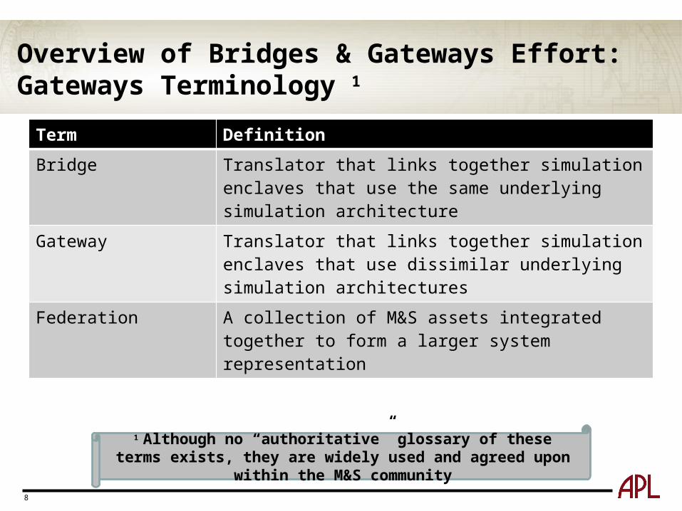
Overview of Bridges & Gateways Effort:Gateways Terminology 1
1 Although no “authoritative” glossary of these terms exists, they are widely used and agreed upon within the M&S community
Term Definition
Bridge Translator that links together simulation enclaves that use the same underlying simulation architecture
Gateway Translator that links together simulation enclaves that use dissimilar underlying simulation architectures
Federation A collection of M&S assets integrated together to form a larger system representation
9
Need for Performance Benchmarks
Purpose
• Allow gateway users to determine if gateways meet their performance requirements
• Allow gateway developers to advertise the performance of their gateway to prospective customers
Goal
• Generate performance numbers based on realistic user environments
Requirement
• Specified test methodology and harness must be sufficiently explicit to allow gateway users or developers to conduct the tests in a repeatable manner
10
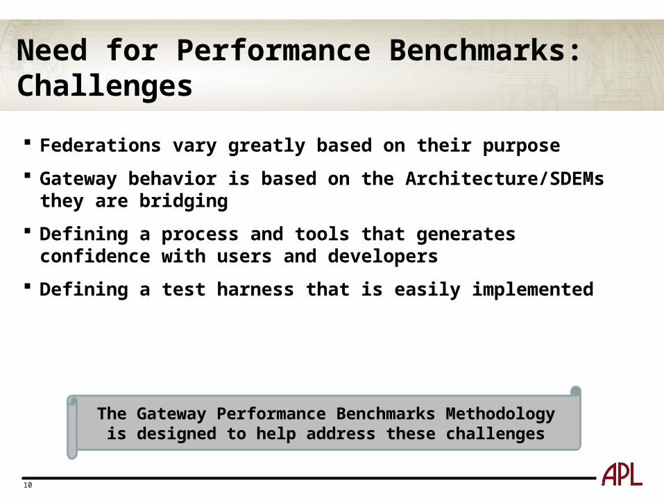
Need for Performance Benchmarks:Challenges
Federations vary greatly based on their purpose
Gateway behavior is based on the Architecture/SDEMs they are bridging
Defining a process and tools that generates confidence with users and developers
Defining a test harness that is easily implemented
The Gateway Performance Benchmarks Methodology is designed to help address these challenges
11
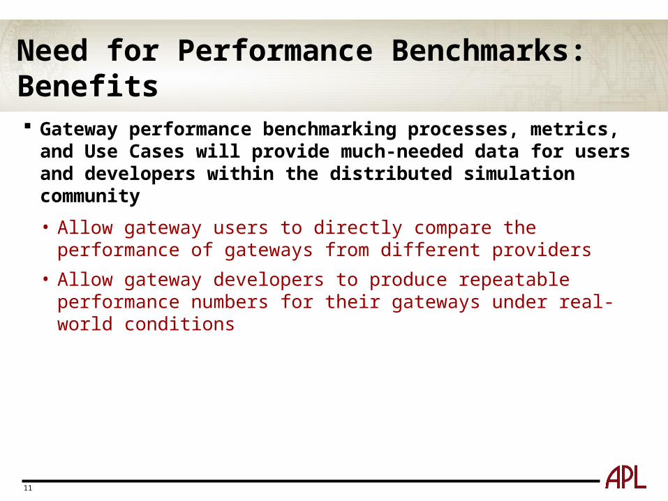
Need for Performance Benchmarks:Benefits Gateway performance benchmarking processes, metrics, and Use
Cases will provide much-needed data for users and developers within the distributed simulation community
• Allow gateway users to directly compare the performance of gateways from different providers
• Allow gateway developers to produce repeatable performance numbers for their gateways under real-world conditions
12
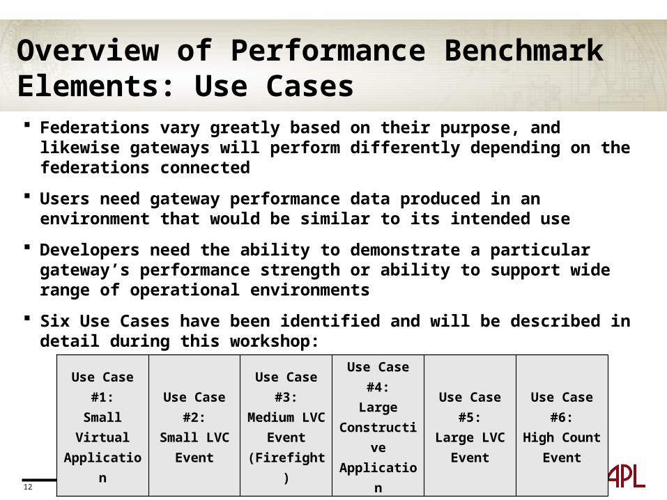
Overview of Performance Benchmark Elements: Use Cases Federations vary greatly based on their purpose, and likewise gateways
will perform differently depending on the federations connected
Users need gateway performance data produced in an environment that would be similar to its intended use
Developers need the ability to demonstrate a particular gateway’s performance strength or ability to support wide range of operational environments
Six Use Cases have been identified and will be described in detail during this workshop:
Use Case #1:Small Virtual Application
Use Case #2:Small LVC
Event
Use Case #3:Medium LVC
Event(Firefight)
Use Case #4:Large
Constructive Application
Use Case #5:Large LVC
Event
Use Case #6:High Count
Event

13
Overview of Performance Benchmark Elements: Metrics To be of value, performance measures need to be relevant, consistent and
usable for the proper assessment of gateway performance
Eight metrics have been defined to cover the most common considerations for measuring performance – latency and throughput
Just as important is the manner in which the metrics data is collected
• All data required for the calculation of performance metrics is collected external to the gateway by a data collector
Latency and throughput metrics are calculated in accordance with the unique rules and characteristics of the transmitted objects
• Transient objects – published once and not updated
• Persistent objects – created and exist for period of time, and may be updated or destroyed
14
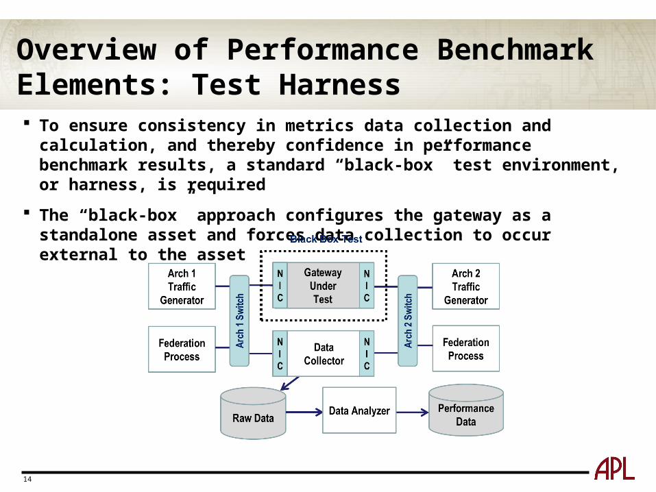
Overview of Performance Benchmark Elements: Test Harness To ensure consistency in metrics data collection and calculation, and
thereby confidence in performance benchmark results, a standard “black-box” test environment, or harness, is required
The “black-box” approach configures the gateway as a standalone asset and forces data collection to occur external to the asset
15
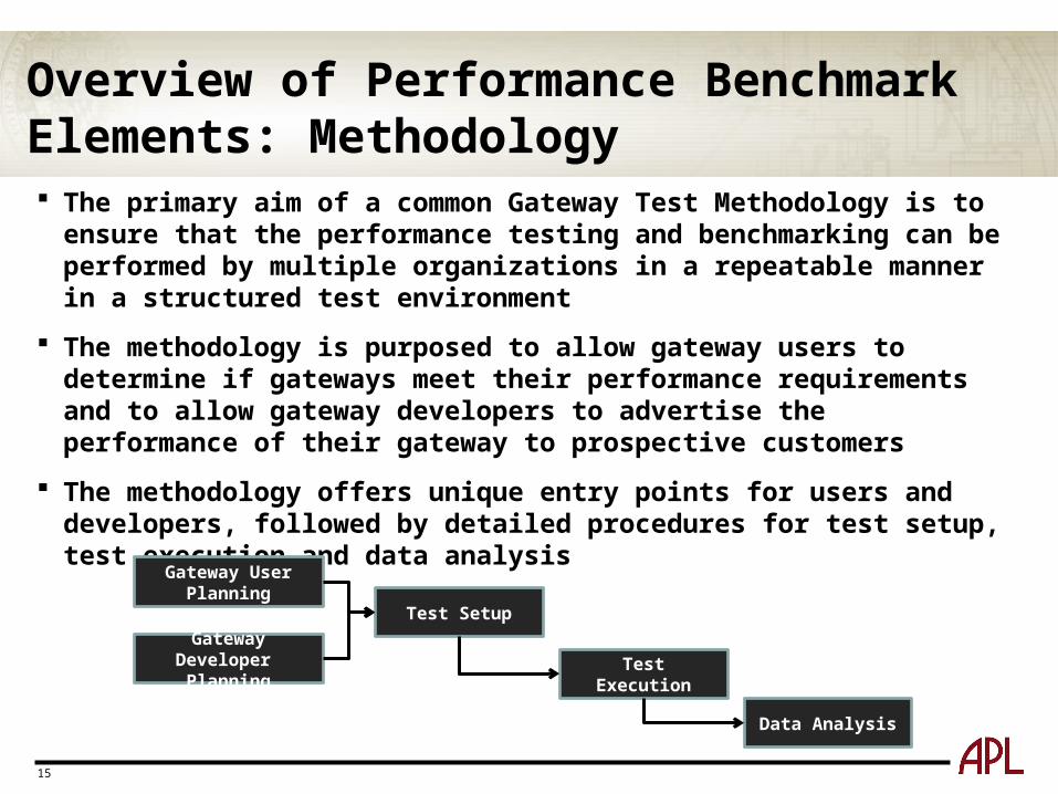
Overview of Performance Benchmark Elements: Methodology The primary aim of a common Gateway Test Methodology is to ensure that
the performance testing and benchmarking can be performed by multiple organizations in a repeatable manner in a structured test environment
The methodology is purposed to allow gateway users to determine if gateways meet their performance requirements and to allow gateway developers to advertise the performance of their gateway to prospective customers
The methodology offers unique entry points for users and developers, followed by detailed procedures for test setup, test execution and data analysis
Gateway User Planning
Gateway Developer Planning
Test Setup
Test Execution
Data Analysis
16
Details: Performance Benchmark Elements
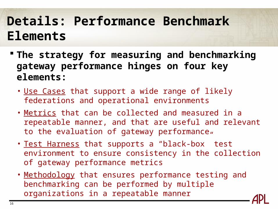
The strategy for measuring and benchmarking gateway performance hinges on four key elements:
• Use Cases that support a wide range of likely federations and operational environments
• Metrics that can be collected and measured in a repeatable manner, and that are useful and relevant to the evaluation of gateway performance
• Test Harness that supports a “black-box” test environment to ensure consistency in the collection of gateway performance metrics
• Methodology that ensures performance testing and benchmarking can be performed by multiple organizations in a repeatable manner
17
Performance Benchmark Elements: Use Cases
Federations vary greatly on their purpose, and thus have very different gateway requirements
• Gateway performance can vary significantly based on federation traffic
Users need to assess gateway performance based on their requirements
Developers may build gateways to support different traffic patterns
To address these needs, six Use Cases based on select Scenario Parameters have been defined
18
Performance Benchmark Elements: Use Cases – Scenario Parameters
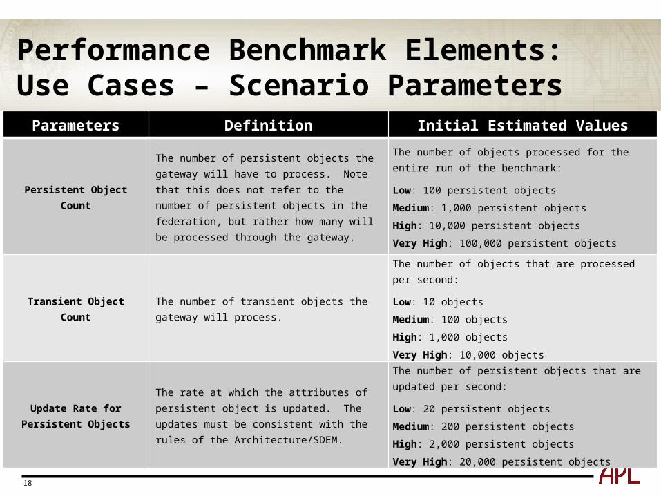
Parameters Definition Initial Estimated Values
Persistent Object Count
The number of persistent objects the gateway will have to process. Note that this does not refer to the number of persistent objects in the federation, but rather how many will be processed through the gateway.
The number of objects processed for the entire run of the benchmark:
Low: 100 persistent objects
Medium: 1,000 persistent objects
High: 10,000 persistent objects
Very High: 100,000 persistent objects
Transient Object CountThe number of transient objects the gateway will process.
The number of objects that are processed per second:
Low: 10 objects
Medium: 100 objects
High: 1,000 objects
Very High: 10,000 objects
Update Rate for Persistent Objects
The rate at which the attributes of persistent object is updated. The updates must be consistent with the rules of the Architecture/SDEM.
The number of persistent objects that are updated per second:
Low: 20 persistent objects
Medium: 200 persistent objects
High: 2,000 persistent objects
Very High: 20,000 persistent objects
19
Performance Benchmark Elements: Use Cases – Scenario Parameters
Parameters Definition Initial Estimated Values
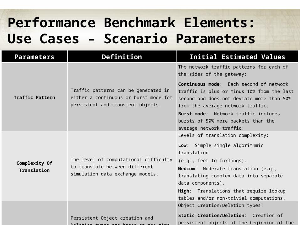
Traffic PatternTraffic patterns can be generated in either a continuous or burst mode for persistent and transient objects.
The network traffic patterns for each of the sides of the gateway:
Continuous mode: Each second of network traffic is plus or minus 10% from the last second and does not deviate more than 50% from the average network traffic.
Burst mode: Network traffic includes bursts of 50% more packets than the average network traffic.
Complexity Of TranslationThe level of computational difficulty to translate between different simulation data exchange models.
Levels of translation complexity:
Low: Simple single algorithmic translation
(e.g., feet to furlongs).
Medium: Moderate translation (e.g., translating complex data into separate data components).
High: Translations that require lookup tables and/or non-trivial computations.
Persistent Object Creation and Deletion
Persistent Object creation and Deletion types are based on the time the objects are created relative to the duration of the simulation exercise.
Object Creation/Deletion types:
Static Creation/Deletion: Creation of persistent objects at the beginning of the simulation execution and deletion at the end of execution.
Dynamic Creation/Deletion: Creation and deletion of objects dynamically during the simulation execution.
20
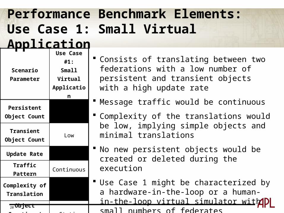
Performance Benchmark Elements: Use Case 1: Small Virtual Application
Scenario Parameter
Use Case #1:Small Virtual Application
Persistent Object Count
Low
Transient Object Count
Low
Update Rate High
Traffic Pattern Continuous
Complexity of Translation
Low
Object Creation /Deletion
Static
Consists of translating between two federations with a low number of persistent and transient objects with a high update rate
Message traffic would be continuous
Complexity of the translations would be low, implying simple objects and minimal translations
No new persistent objects would be created or deleted during the execution
Use Case 1 might be characterized by a hardware-in-the-loop or a human-in-the-loop virtual simulator with small numbers of federates
21
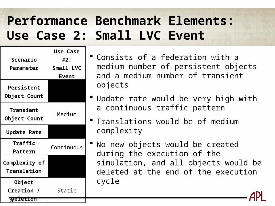
Performance Benchmark Elements: Use Case 2: Small LVC Event
Scenario Parameter
Use Case #2:Small LVC
Event
Persistent Object Count
Medium
Transient Object Count
Medium
Update Rate Very High
Traffic Pattern Continuous
Complexity of Translation
Medium
Object Creation /Deletion
Static
Consists of a federation with a medium number of persistent objects and a medium number of transient objects
Update rate would be very high with a continuous traffic pattern
Translations would be of medium complexity
No new objects would be created during the execution of the simulation, and all objects would be deleted at the end of the execution cycle
22
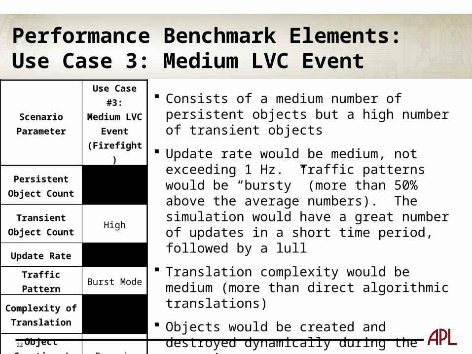
Performance Benchmark Elements: Use Case 3: Medium LVC Event
Scenario Parameter
Use Case #3:Medium LVC
Event(Firefight)
Persistent Object Count
Medium
Transient Object Count
High
Update Rate Medium
Traffic Pattern Burst Mode
Complexity of Translation
Medium
Object Creation /Deletion
Dynamic
Consists of a medium number of persistent objects but a high number of transient objects
Update rate would be medium, not exceeding 1 Hz. Traffic patterns would be “bursty” (more than 50% above the average numbers). The simulation would have a great number of updates in a short time period, followed by a lull
Translation complexity would be medium (more than direct algorithmic translations)
Objects would be created and destroyed dynamically during the execution
This Use Case is representative of a typical firefight simulation

23
Performance Benchmark Elements: Use Case 4: Large Constructive Application
Scenario Parameter
Use Case #4:Large
Constructive Application
Persistent Object Count
High
Transient Object Count
Medium
Update Rate Low
Traffic Pattern Burst Mode
Complexity of Translation
High
Object Creation /Deletion
Dynamic
Consists of a high number of persistent objects (greater than 10,000) and a medium number of transient objects (100 per second)
Update rate would be low (20 persistent objects updated per second)
Traffic pattern would be bursty
Translation complexity would be high
Objects would be created and destroyed dynamically during the execution
24
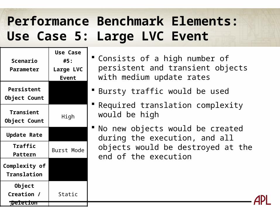
Performance Benchmark Elements: Use Case 5: Large LVC Event
Scenario Parameter
Use Case #5:Large LVC
Event
Persistent Object Count
High
Transient Object Count
High
Update Rate Medium
Traffic Pattern Burst Mode
Complexity of Translation
High
Object Creation /Deletion
Static
Consists of a high number of persistent and transient objects with medium update rates
Bursty traffic would be used
Required translation complexity would be high
No new objects would be created during the execution, and all objects would be destroyed at the end of the execution
25
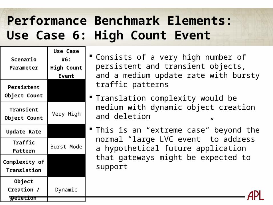
Performance Benchmark Elements: Use Case 6: High Count Event
Scenario Parameter
Use Case #6:High Count
Event
Persistent Object Count
Very High
Transient Object Count
Very High
Update Rate Medium
Traffic Pattern Burst Mode
Complexity of Translation
Medium
Object Creation /Deletion
Dynamic
Consists of a very high number of persistent and transient objects, and a medium update rate with bursty traffic patterns
Translation complexity would be medium with dynamic object creation and deletion
This is an “extreme case” beyond the normal “large LVC event” to address a hypothetical future application that gateways might be expected to support
26
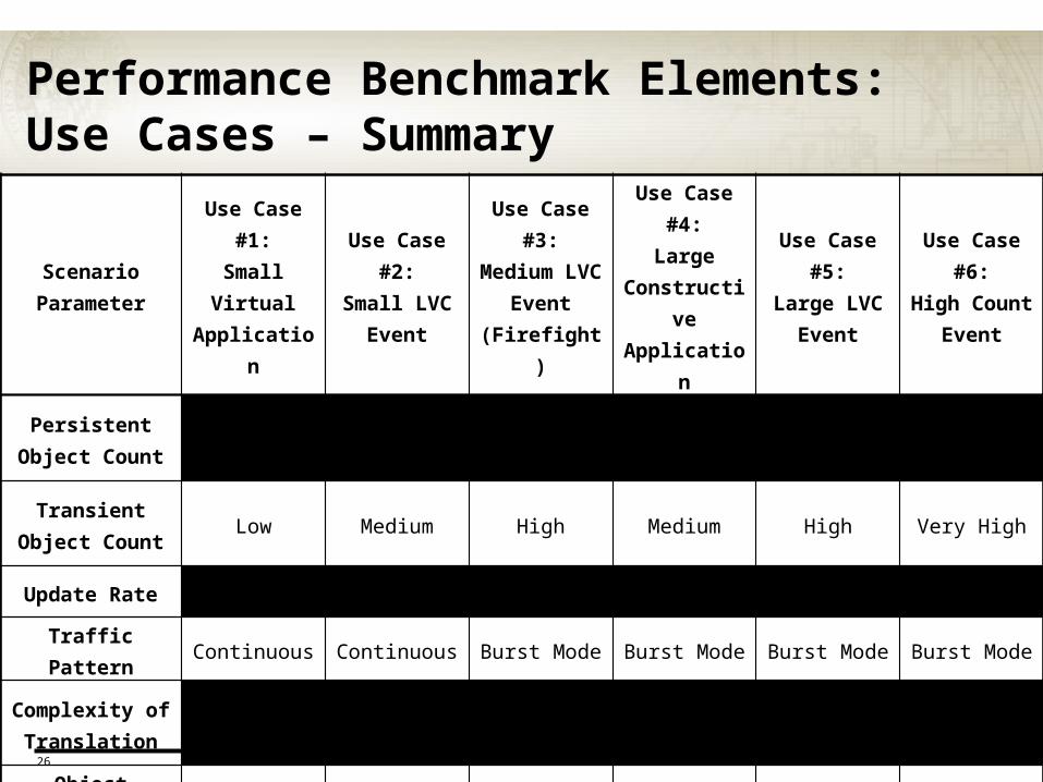
Performance Benchmark Elements: Use Cases – Summary
Scenario Parameter
Use Case #1:Small Virtual Application
Use Case #2:Small LVC
Event
Use Case #3:Medium LVC
Event(Firefight)
Use Case #4:Large
Constructive Application
Use Case #5:Large LVC
Event
Use Case #6:High Count
Event
Persistent Object Count
Low Medium Medium High High Very High
Transient Object Count
Low Medium High Medium High Very High
Update Rate High Very High Medium Low Medium Medium
Traffic Pattern Continuous Continuous Burst Mode Burst Mode Burst Mode Burst Mode
Complexity of Translation
Low Medium Medium High High Medium
Object Creation /Deletion
Static Static Dynamic Dynamic Static Dynamic
27
Performance Benchmark Elements: Metrics Federation users apply gateways in unique and diverse ways, making the
need for a common and relevant set of performance metrics essential to performance benchmarking
A previous workshop considered six metrics for measuring performance:
• Resource Utilization, Latency, Throughput, Scalability, Stability, Accuracy
However, it was concluded that most federations are interested in two metrics:
• Latency and Throughput
The nature of gateways makes this complicated, as Architectures and Simulation Data Exchange Models (SDEMs) have different publishing rules
• All data does not pass between both sides of a gateway
Latency and Throughput are relatively easy to derive for transient objects, but are more challenging to collect for persistent objects
28
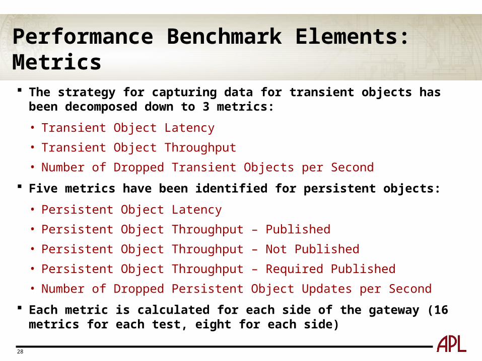
Performance Benchmark Elements: Metrics The strategy for capturing data for transient objects has been decomposed
down to 3 metrics:
• Transient Object Latency
• Transient Object Throughput
• Number of Dropped Transient Objects per Second
Five metrics have been identified for persistent objects:
• Persistent Object Latency
• Persistent Object Throughput – Published
• Persistent Object Throughput – Not Published
• Persistent Object Throughput – Required Published
• Number of Dropped Persistent Object Updates per Second
Each metric is calculated for each side of the gateway (16 metrics for each test, eight for each side)
29
Performance Benchmark Elements: MetricsMetric Description Calculation
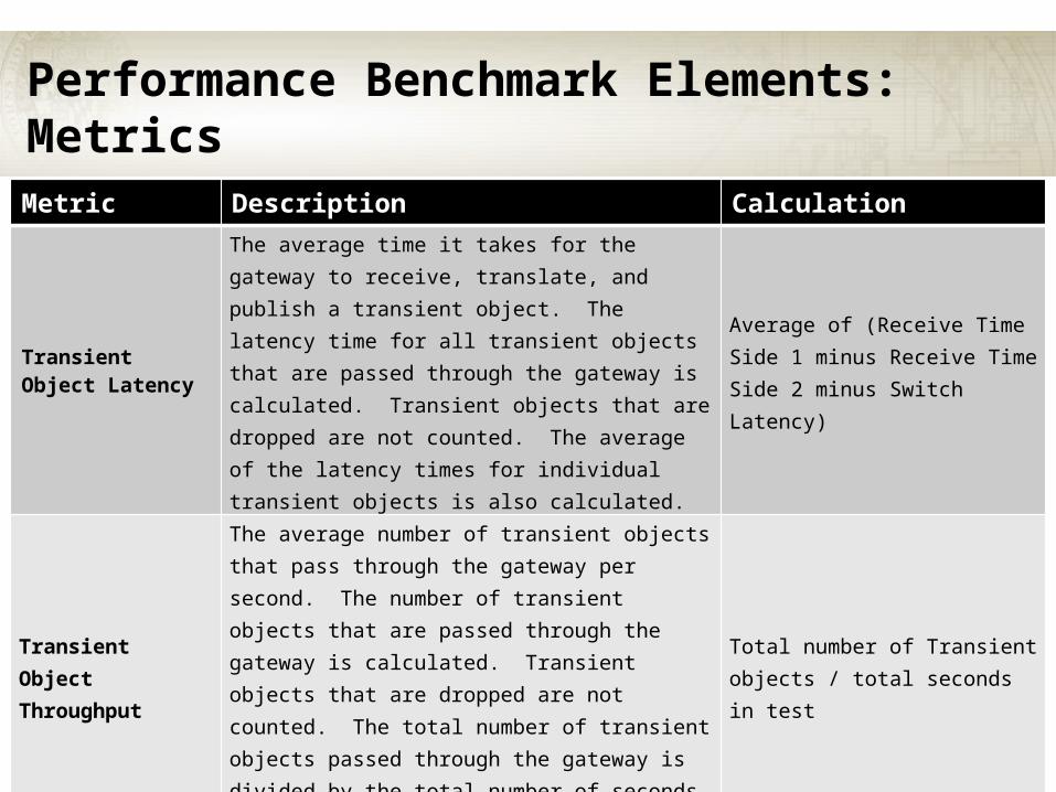
Transient Object Latency
The average time it takes for the gateway to receive, translate, and publish a transient object. The latency time for all transient objects that are passed through the gateway is calculated. Transient objects that are dropped are not counted. The average of the latency times for individual transient objects is also calculated.
Average of (Receive Time Side 1 minus Receive Time Side 2 minus Switch Latency)
Transient Object Throughput
The average number of transient objects that pass through the gateway per second. The number of transient objects that are passed through the gateway is calculated. Transient objects that are dropped are not counted. The total number of transient objects passed through the gateway is divided by the total number of seconds in the test.
Total number of Transient objects / total seconds in test
Number of Dropped Transient Objects per Second
The number of transient objects received on one side of the gateway, but not published to the other side.
(Number of transient objects received by Side 1 minus Number of transient objects published on Side 2) / total seconds in test
30
Performance Benchmark Elements: MetricsMetric Description Calculation
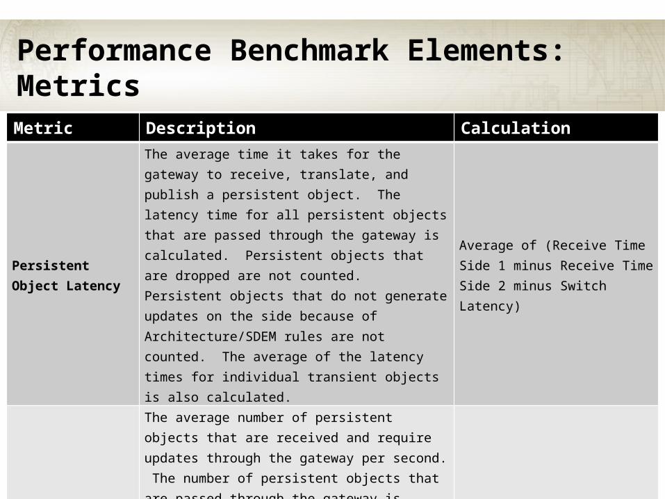
Persistent Object Latency
The average time it takes for the gateway to receive, translate, and publish a persistent object. The latency time for all persistent objects that are passed through the gateway is calculated. Persistent objects that are dropped are not counted. Persistent objects that do not generate updates on the side because of Architecture/SDEM rules are not counted. The average of the latency times for individual transient objects is also calculated.
Average of (Receive Time Side 1 minus Receive Time Side 2 minus Switch Latency)
Persistent Object Throughput – Published
The average number of persistent objects that are received and require updates through the gateway per second. The number of persistent objects that are passed through the gateway is calculated. Persistent objects that are dropped are not counted. Persistent objects received that do not require publishing on the other side are not counted. The total number of persistent objects passed through the gateway is divided by the total number of seconds in the test.
Total number of received Persistent objects that require update / total seconds in test

31
Performance Benchmark Elements: MetricsMetric Description Calculation
Persistent Object Throughput – Not Published
The average number of persistent objects that are received and do not require updates through the gateway per second. A count is taken of the number of persistent objects that are received, but not passed through the gateway. The total number of persistent objects received, but not passed through the gateway is divided by the total number of seconds in the test.
Total number of received Persistent objects that do not require update / total seconds in test
Persistent Object Throughput – Required Published
The average number of persistent objects that are not based on updates to be published by gateway per second. A count is taken of the number of persistent objects that are published by the gateway based on the rules of the Architecture/SDEM and not because of a received object. The total number of persistent objects published not based on an update by the gateway is divided by the total number of seconds in the test.
Total number of published Persistent objects that are not based on updates / total seconds in test
32
Performance Benchmark Elements: MetricsMetric Description Calculation
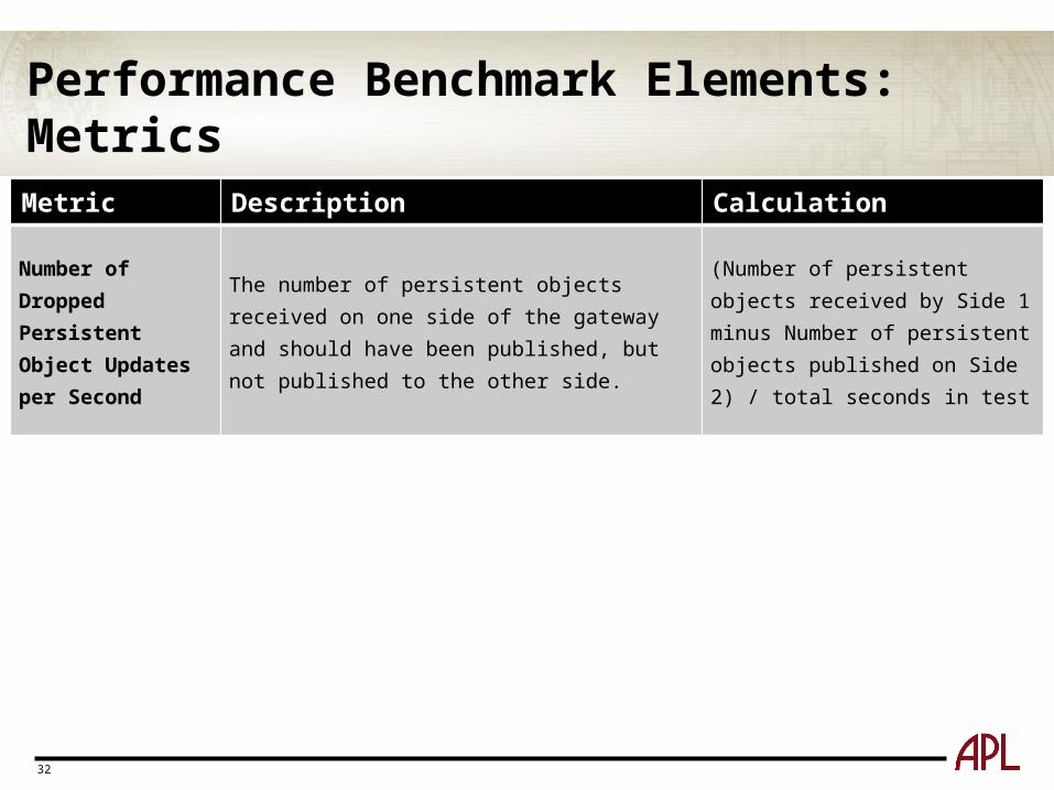
Number of Dropped Persistent Object Updates per Second
The number of persistent objects received on one side of the gateway and should have been published, but not published to the other side.
(Number of persistent objects received by Side 1 minus Number of persistent objects published on Side 2) / total seconds in test
33
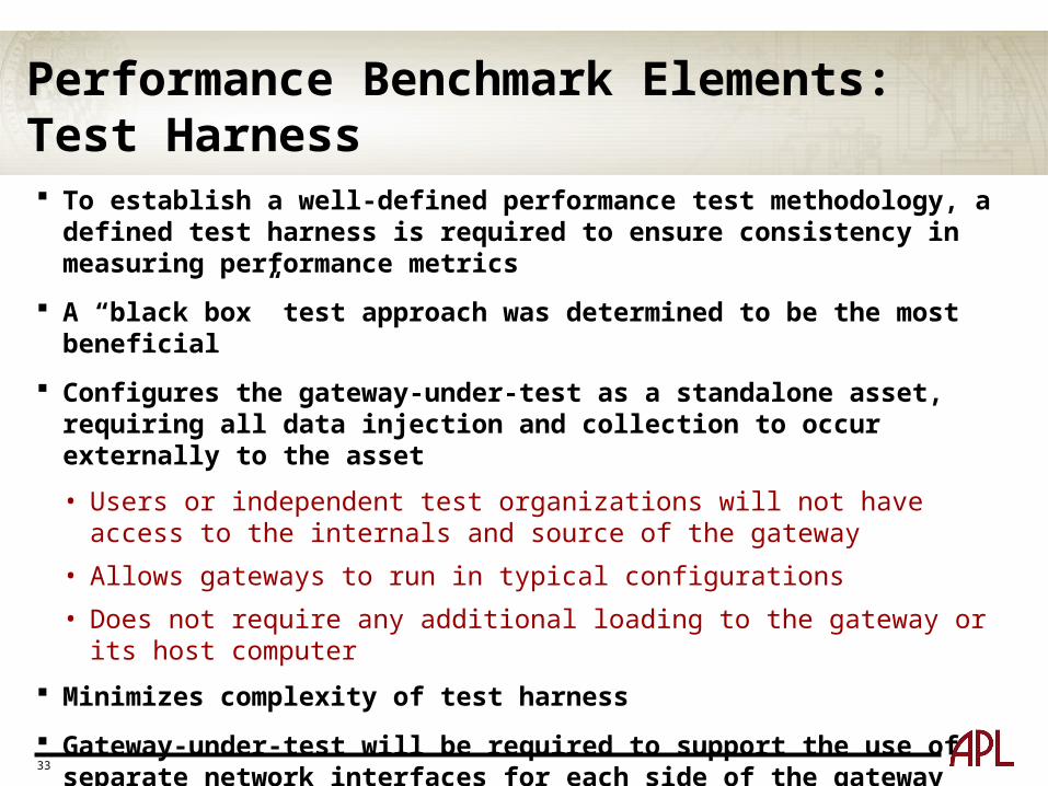
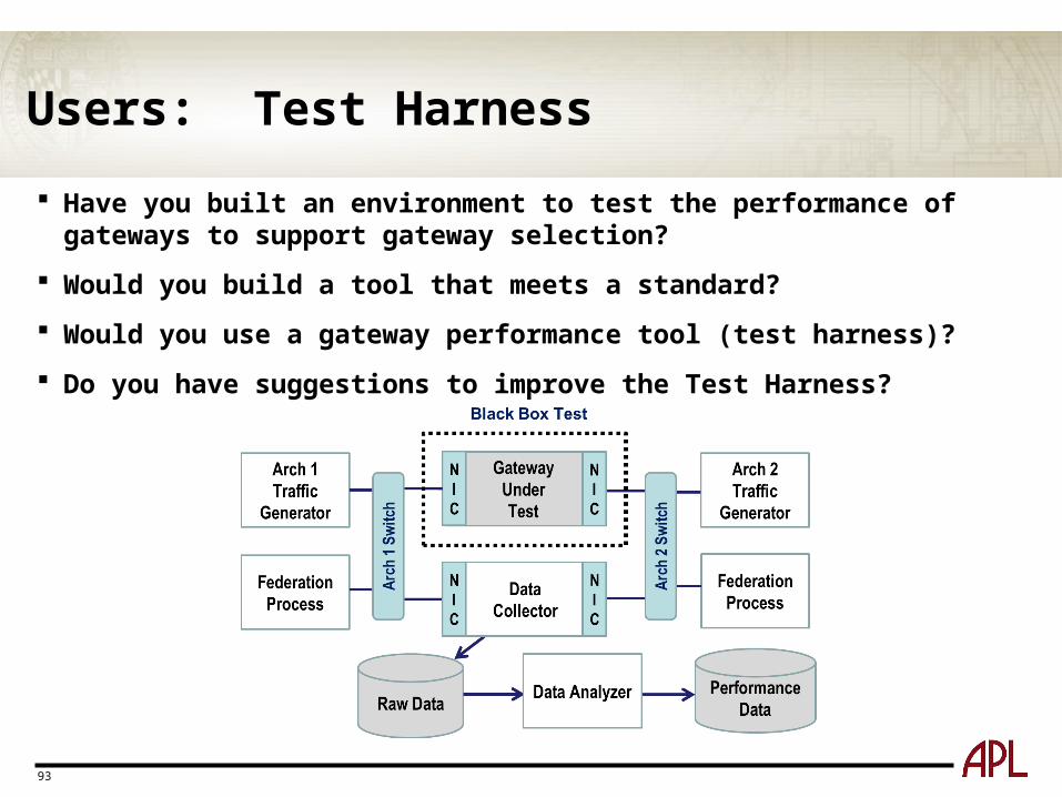
Performance Benchmark Elements: Test Harness To establish a well-defined performance test methodology, a defined test
harness is required to ensure consistency in measuring performance metrics
A “black box” test approach was determined to be the most beneficial
Configures the gateway-under-test as a standalone asset, requiring all data injection and collection to occur externally to the asset
• Users or independent test organizations will not have access to the internals and source of the gateway
• Allows gateways to run in typical configurations
• Does not require any additional loading to the gateway or its host computer
Minimizes complexity of test harness
Gateway-under-test will be required to support the use of separate network interfaces for each side of the gateway
34
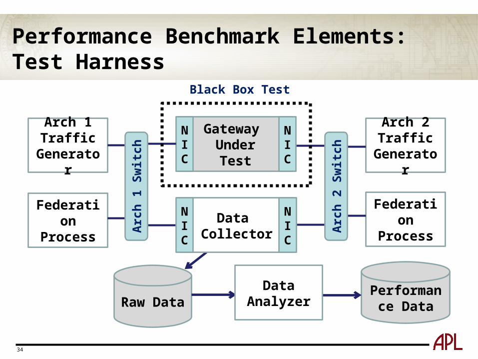
Performance Benchmark Elements: Test Harness
Gateway UnderTest
NIC
Arch 1Traffic
Generator
Arch 2Traffic
Generator
Raw DataPerformance
Data
Black Box Test
Federation Process
Federation Process
Arc
h 1
Switc
h
Data Collector
Arc
h 2
Switc
h
NIC
NIC
NIC
Data Analyzer
35
Performance Benchmark Elements: Test Harness – Traffic Generators
Traffic generators are used to simulate a federation
Traffic profiles are defined by the Use Case selected for the test
Traffic generators must be able to support all distributed simulation architectures
• One traffic generator that supports all architectures or multiple traffic generators supporting specific architectures
Existing semi-automated forces (SAFs) or other appropriate simulations may be used as traffic generators.
The Test Harness supports flexibility in traffic generators
• However, they must be able to produce the required traffic profiles as specified in the Use Cases

36
Performance Benchmark Elements: Test Harness – Data Collector The data collector records the data used to create performance metrics for
the gateway
Hosted on a single computer that uses two Network Interface Cards (NIC), allowing the data collector to join both federations on separate networks
The data collector must be able to join both federations and subscribe to the required objects
It is critical that the data collector not drop any object updates, as this will invalidate the performance metrics calculated for the gateway
Considerations as to how the recorded data will be stored are critical to the performance of the data collector
• The data collector shall record all of the data in objects along with the time of arrival; This is required so that the data analyzer can determine if updates on the other side of the gateway were required
37
Performance Benchmark Elements: Test Harness – Data Analyzer
The data analyzer is the most complex component in the harness
Calculates all of the required metrics based on the file produced by the data collector
Determines if the measured traffic flow meets the requirements of the Use Case
Because different architectures have different rules for updates, the data analyzer must understand these rules to determine if an update should occur
Information on the architecture’s publication rules is stored in profiles for each Architecture/SDEM pair
38
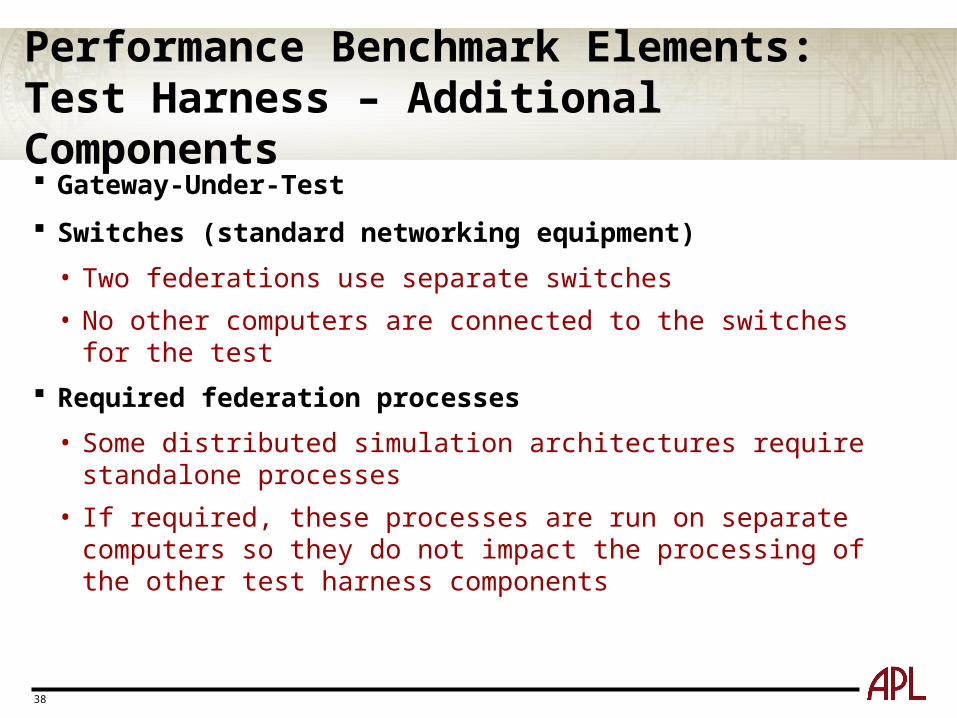
Performance Benchmark Elements: Test Harness – Additional Components Gateway-Under-Test
Switches (standard networking equipment)
• Two federations use separate switches
• No other computers are connected to the switches for the test
Required federation processes
• Some distributed simulation architectures require standalone processes
• If required, these processes are run on separate computers so they do not impact the processing of the other test harness components
39
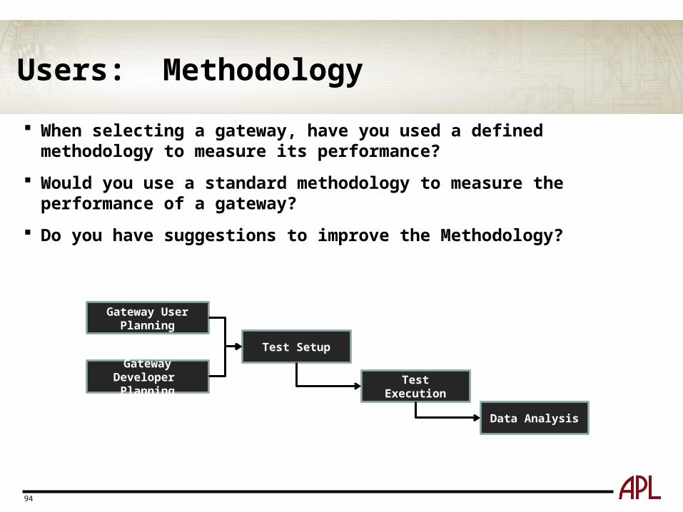
Methodology: Overview
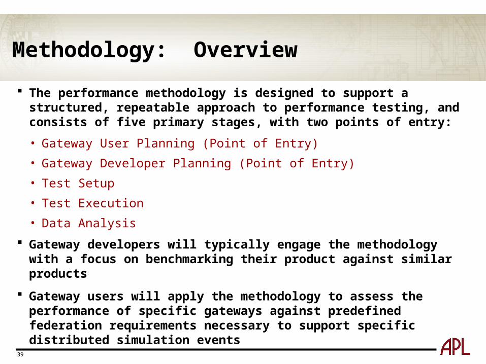
The performance methodology is designed to support a structured, repeatable approach to performance testing, and consists of five primary stages, with two points of entry:
• Gateway User Planning (Point of Entry)
• Gateway Developer Planning (Point of Entry)
• Test Setup
• Test Execution
• Data Analysis
Gateway developers will typically engage the methodology with a focus on benchmarking their product against similar products
Gateway users will apply the methodology to assess the performance of specific gateways against predefined federation requirements necessary to support specific distributed simulation events
40
Methodology: Overview
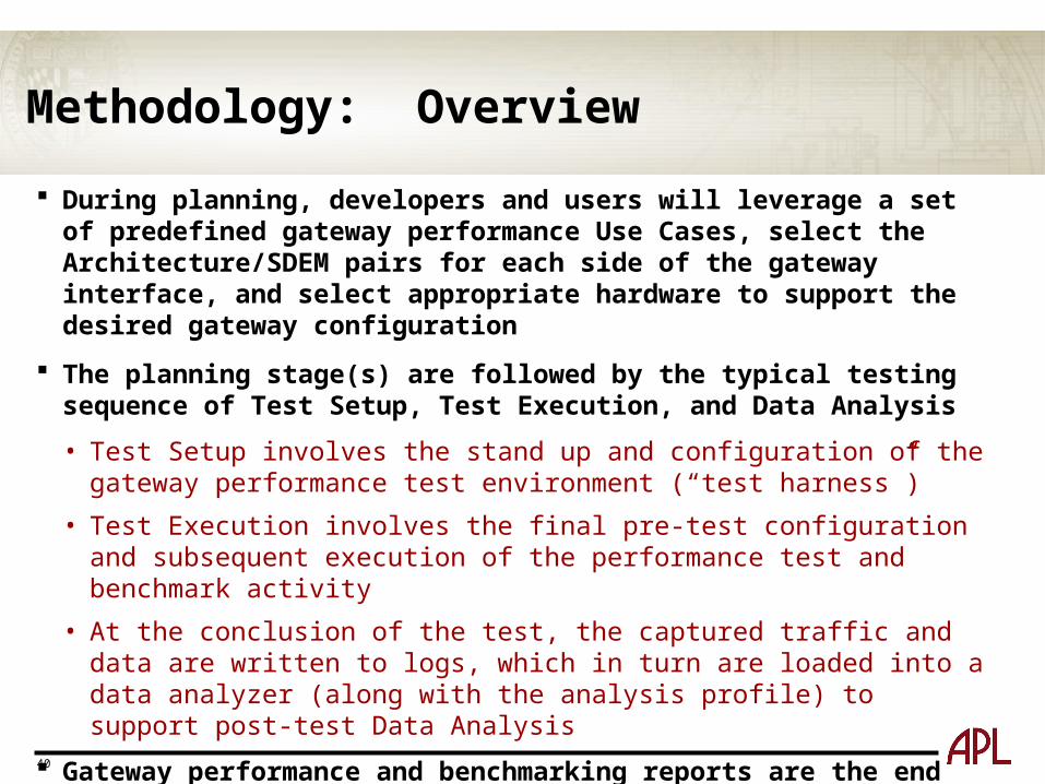
During planning, developers and users will leverage a set of predefined gateway performance Use Cases, select the Architecture/SDEM pairs for each side of the gateway interface, and select appropriate hardware to support the desired gateway configuration
The planning stage(s) are followed by the typical testing sequence of Test Setup, Test Execution, and Data Analysis
• Test Setup involves the stand up and configuration of the gateway performance test environment (“test harness”)
• Test Execution involves the final pre-test configuration and subsequent execution of the performance test and benchmark activity
• At the conclusion of the test, the captured traffic and data are written to logs, which in turn are loaded into a data analyzer (along with the analysis profile) to support post-test Data Analysis
Gateway performance and benchmarking reports are the end products of the Data Analysis stage and of the overall methodology
41
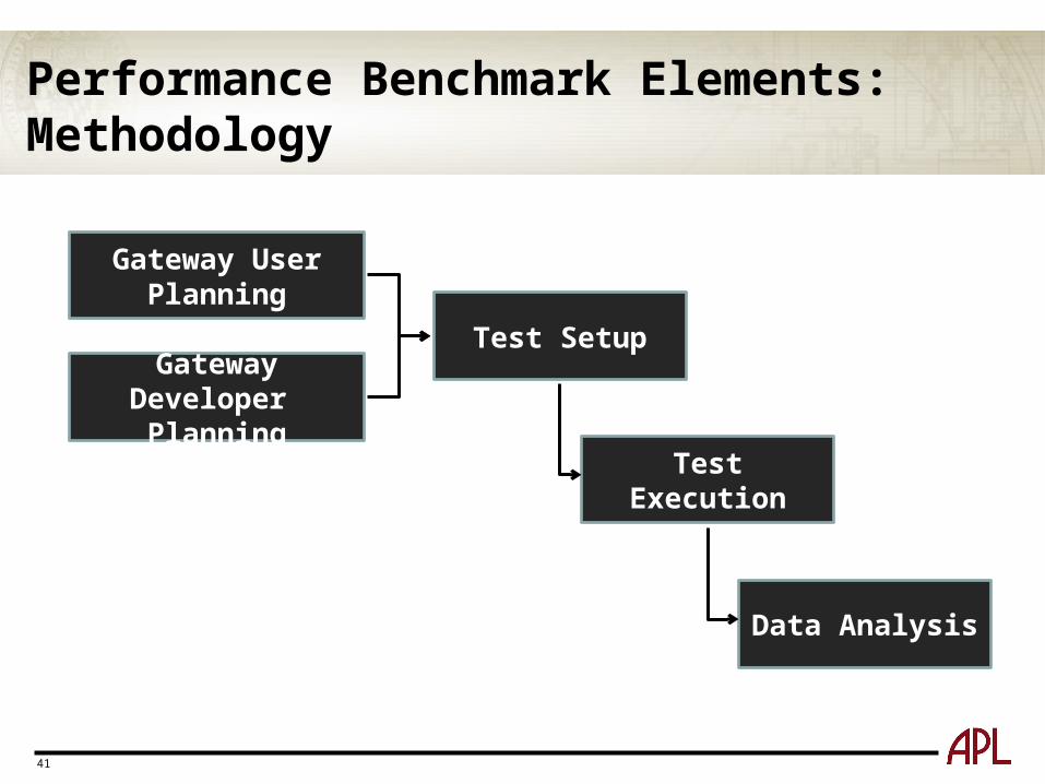
Performance Benchmark Elements: Methodology
Gateway User Planning
Gateway Developer Planning
Test Setup
Test Execution
Data Analysis
42
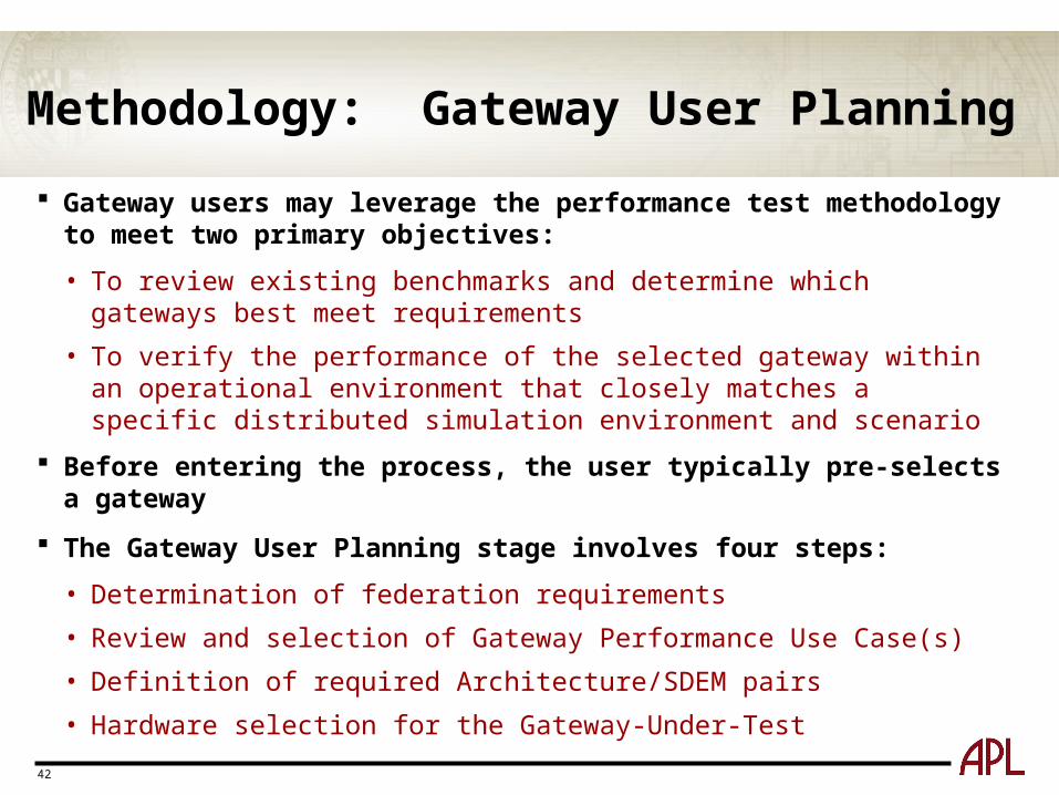
Methodology: Gateway User Planning
Gateway users may leverage the performance test methodology to meet two primary objectives:
• To review existing benchmarks and determine which gateways best meet requirements
• To verify the performance of the selected gateway within an operational environment that closely matches a specific distributed simulation environment and scenario
Before entering the process, the user typically pre-selects a gateway
The Gateway User Planning stage involves four steps:
• Determination of federation requirements
• Review and selection of Gateway Performance Use Case(s)
• Definition of required Architecture/SDEM pairs
• Hardware selection for the Gateway-Under-Test

43
Gateway User Planning: Steps
Gateway User Planning
Define which Architecture/
SDEM Pairs are Needed
Select Hardware for Gateway Based on Federation Needs
Review & Determine which Gateway Performance Use Case(s) Meet Requirements
Determine Federation Requirements
Test Setup
44
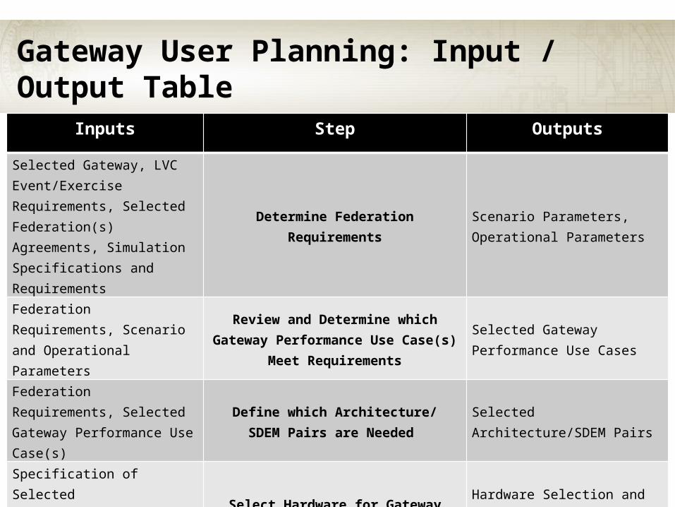
Gateway User Planning: Input / Output Table
Inputs Step Outputs
Selected Gateway, LVC Event/Exercise Requirements, Selected Federation(s) Agreements, Simulation Specifications and Requirements
Determine Federation RequirementsScenario Parameters, Operational Parameters
Federation Requirements, Scenario and Operational Parameters
Review and Determine which Gateway Performance Use Case(s) Meet
Requirements
Selected Gateway Performance Use Cases
Federation Requirements, Selected Gateway Performance Use Case(s)
Define which Architecture/SDEM Pairs are Needed
Selected Architecture/SDEM Pairs
Specification of Selected Architecture/SDEM Pairs, Gateway Performance Use Cases
Select Hardware for Gateway Based on Federation Needs
Hardware Selection and Configuration for the Gateway-Under-Test
45
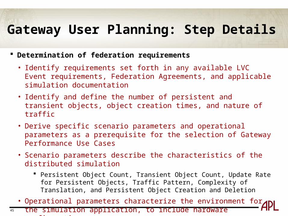
Gateway User Planning: Step Details
Determination of federation requirements
• Identify requirements set forth in any available LVC Event requirements, Federation Agreements, and applicable simulation documentation
• Identify and define the number of persistent and transient objects, object creation times, and nature of traffic
• Derive specific scenario parameters and operational parameters as a prerequisite for the selection of Gateway Performance Use Cases
• Scenario parameters describe the characteristics of the distributed simulation Persistent Object Count, Transient Object Count, Update Rate for Persistent
Objects, Traffic Pattern, Complexity of Translation, and Persistent Object Creation and Deletion
• Operational parameters characterize the environment for the simulation application, to include hardware configuration
Number of Connected Simulation Architectures, Number of Connected Simulated Components, Central Processing Unit (CPU) Processing Power, Computer Memory Capacity, Disk Performance, and Network Configuration/Speed
• Review and selection of Gateway Performance Use Case(s)
• Definition of required Architecture/SDEM pairs
• Hardware selection for the Gateway-Under-Test
46
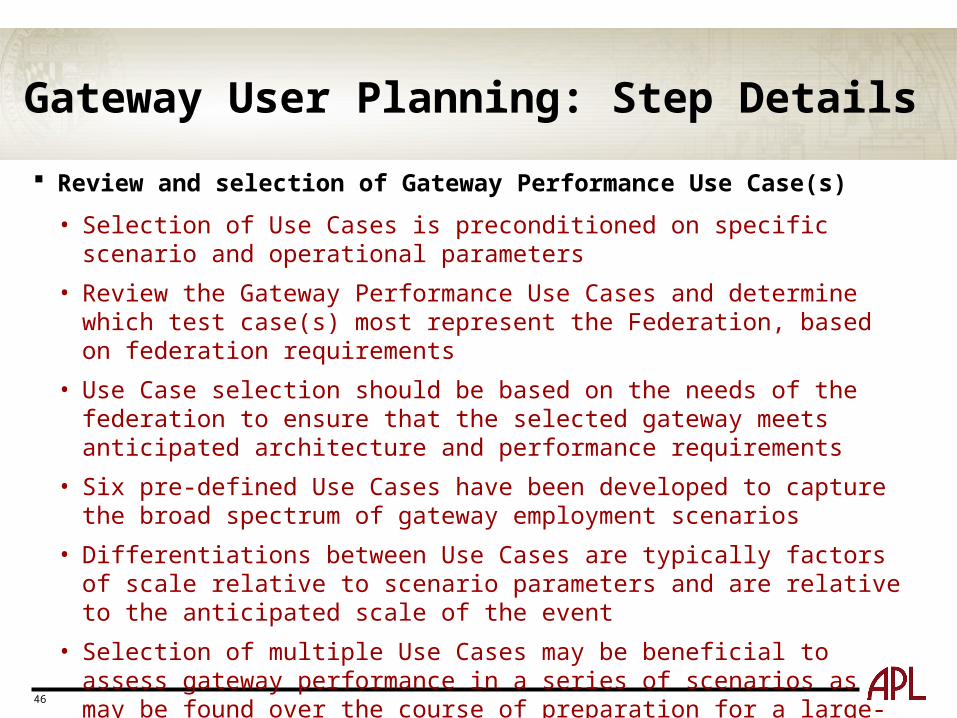
Gateway User Planning: Step Details
Review and selection of Gateway Performance Use Case(s)
• Selection of Use Cases is preconditioned on specific scenario and operational parameters
• Review the Gateway Performance Use Cases and determine which test case(s) most represent the Federation, based on federation requirements
• Use Case selection should be based on the needs of the federation to ensure that the selected gateway meets anticipated architecture and performance requirements
• Six pre-defined Use Cases have been developed to capture the broad spectrum of gateway employment scenarios
• Differentiations between Use Cases are typically factors of scale relative to scenario parameters and are relative to the anticipated scale of the event
• Selection of multiple Use Cases may be beneficial to assess gateway performance in a series of scenarios as may be found over the course of preparation for a large-scale distributed simulation event
47
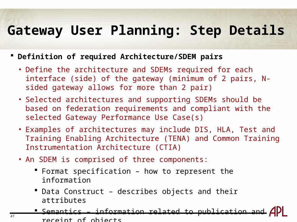
Gateway User Planning: Step Details
Definition of required Architecture/SDEM pairs
• Define the architecture and SDEMs required for each interface (side) of the gateway (minimum of 2 pairs, N-sided gateway allows for more than 2 pair)
• Selected architectures and supporting SDEMs should be based on federation requirements and compliant with the selected Gateway Performance Use Case(s)
• Examples of architectures may include DIS, HLA, Test and Training Enabling Architecture (TENA) and Common Training Instrumentation Architecture (CTIA)
• An SDEM is comprised of three components:
Format specification – how to represent the information Data Construct – describes objects and their attributes Semantics – information related to publication and receipt of objects
48
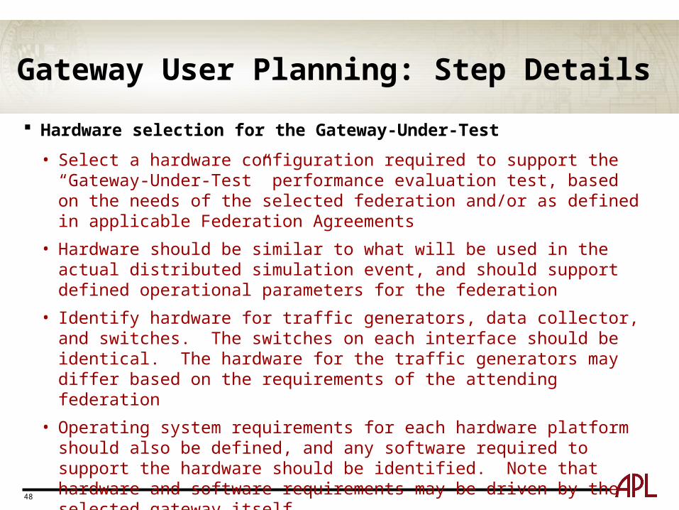
Gateway User Planning: Step Details
Hardware selection for the Gateway-Under-Test
• Select a hardware configuration required to support the “Gateway-Under-Test” performance evaluation test, based on the needs of the selected federation and/or as defined in applicable Federation Agreements
• Hardware should be similar to what will be used in the actual distributed simulation event, and should support defined operational parameters for the federation
• Identify hardware for traffic generators, data collector, and switches. The switches on each interface should be identical. The hardware for the traffic generators may differ based on the requirements of the attending federation
• Operating system requirements for each hardware platform should also be defined, and any software required to support the hardware should be identified. Note that hardware and software requirements may be driven by the selected gateway itself
49
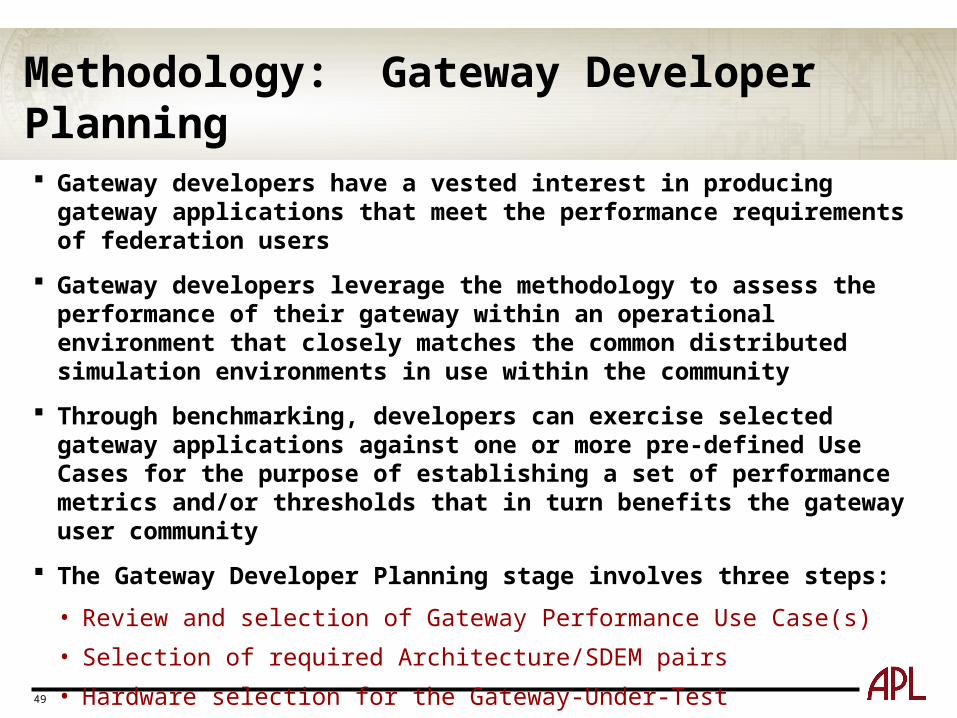
Methodology: Gateway Developer Planning
Gateway developers have a vested interest in producing gateway applications that meet the performance requirements of federation users
Gateway developers leverage the methodology to assess the performance of their gateway within an operational environment that closely matches the common distributed simulation environments in use within the community
Through benchmarking, developers can exercise selected gateway applications against one or more pre-defined Use Cases for the purpose of establishing a set of performance metrics and/or thresholds that in turn benefits the gateway user community
The Gateway Developer Planning stage involves three steps:
• Review and selection of Gateway Performance Use Case(s)
• Selection of required Architecture/SDEM pairs
• Hardware selection for the Gateway-Under-Test
50
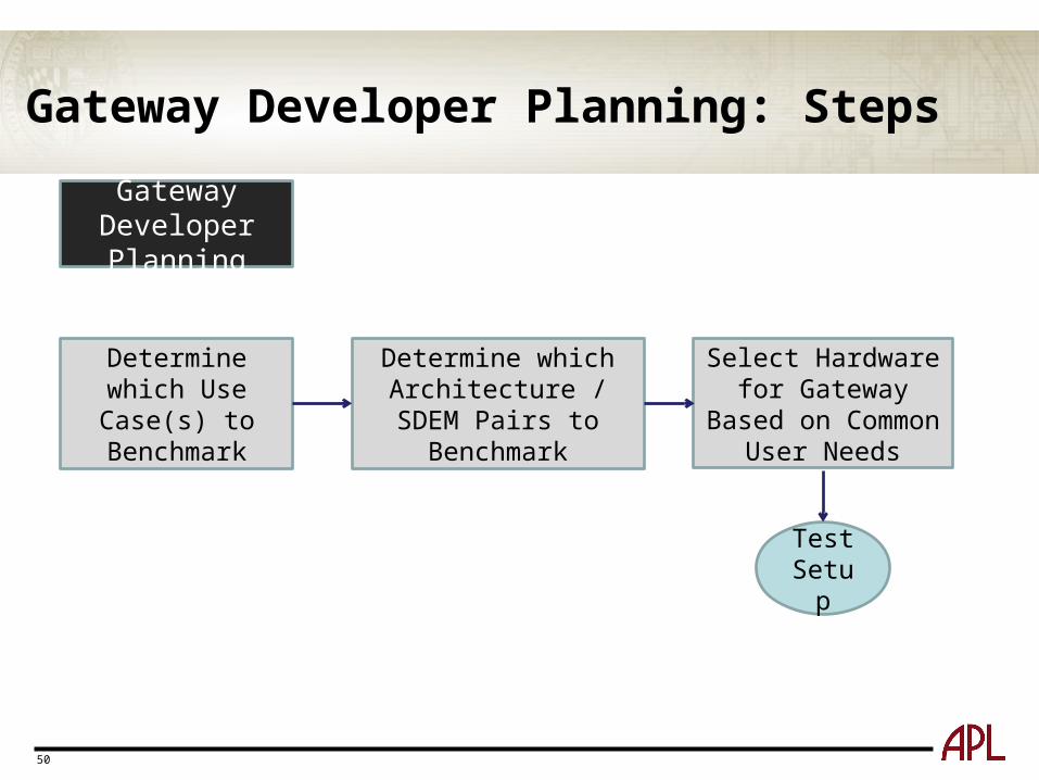
Gateway Developer Planning: Steps
Select Hardware for Gateway Based on
Common User Needs
Determine which Architecture / SDEM Pairs to
Benchmark
Determine which Use Case(s) to Benchmark
Test Setup
Gateway Developer Planning
51
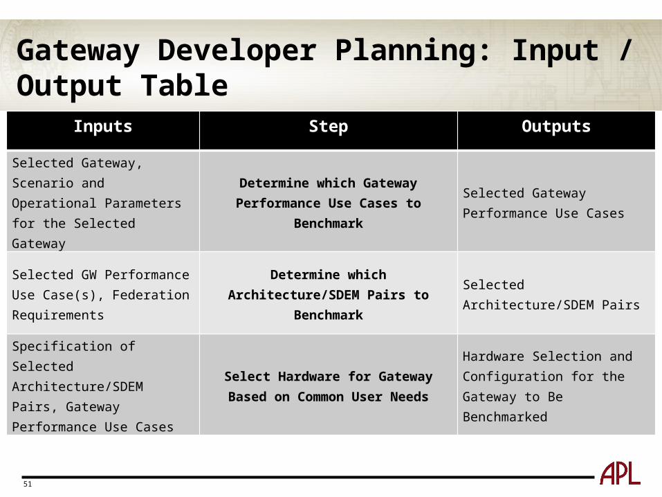
Gateway Developer Planning: Input / Output Table
Inputs Step Outputs
Selected Gateway, Scenario and Operational Parameters for the Selected Gateway
Determine which Gateway Performance Use Cases to Benchmark
Selected Gateway Performance Use Cases
Selected GW Performance Use Case(s), Federation Requirements
Determine which Architecture/SDEM Pairs to Benchmark
Selected Architecture/SDEM Pairs
Specification of Selected Architecture/SDEM Pairs, Gateway Performance Use Cases
Select Hardware for Gateway Based on Common User Needs
Hardware Selection and Configuration for the Gateway to Be Benchmarked
52
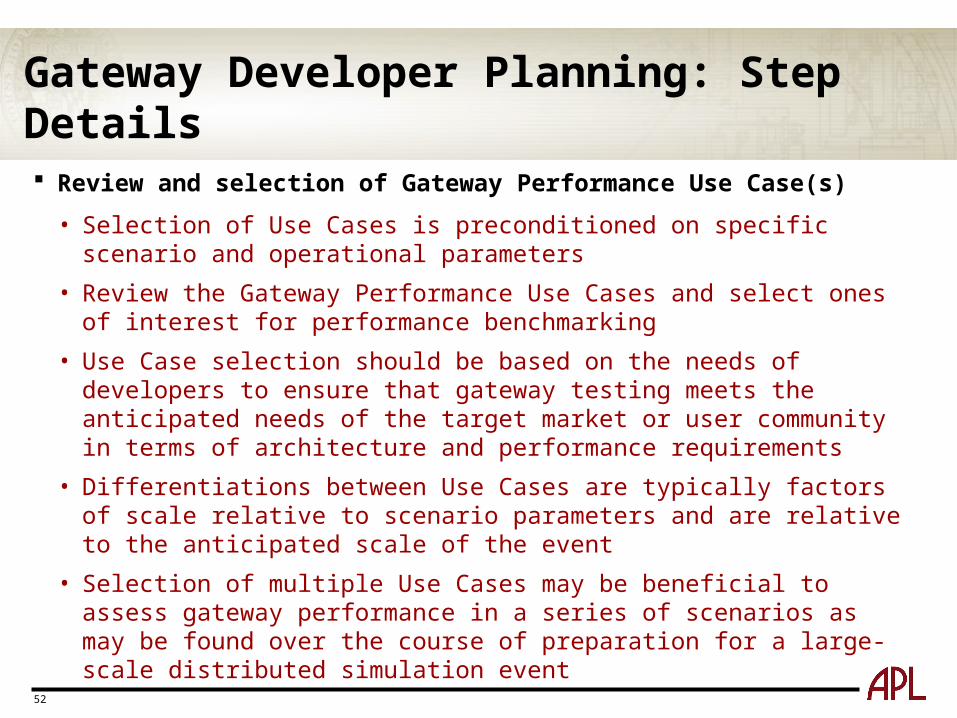
Gateway Developer Planning: Step Details
Review and selection of Gateway Performance Use Case(s)
• Selection of Use Cases is preconditioned on specific scenario and operational parameters
• Review the Gateway Performance Use Cases and select ones of interest for performance benchmarking
• Use Case selection should be based on the needs of developers to ensure that gateway testing meets the anticipated needs of the target market or user community in terms of architecture and performance requirements
• Differentiations between Use Cases are typically factors of scale relative to scenario parameters and are relative to the anticipated scale of the event
• Selection of multiple Use Cases may be beneficial to assess gateway performance in a series of scenarios as may be found over the course of preparation for a large-scale distributed simulation event
53
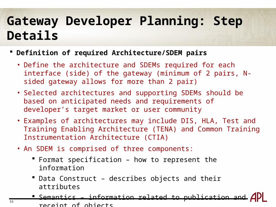
Gateway Developer Planning: Step Details
Definition of required Architecture/SDEM pairs
• Define the architecture and SDEMs required for each interface (side) of the gateway (minimum of 2 pairs, N-sided gateway allows for more than 2 pair)
• Selected architectures and supporting SDEMs should be based on anticipated needs and requirements of developer’s target market or user community
• Examples of architectures may include DIS, HLA, Test and Training Enabling Architecture (TENA) and Common Training Instrumentation Architecture (CTIA)
• An SDEM is comprised of three components:
Format specification – how to represent the information Data Construct – describes objects and their attributes Semantics – information related to publication and receipt of objects
• Developers select Architecture/SDEM pairs based on applicable and anticipated federation requirements against which the gateway is to be benchmarked
54
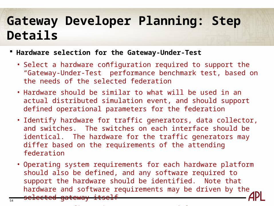
Gateway Developer Planning: Step Details
Hardware selection for the Gateway-Under-Test
• Select a hardware configuration required to support the “Gateway-Under-Test” performance benchmark test, based on the needs of the selected federation
• Hardware should be similar to what will be used in an actual distributed simulation event, and should support defined operational parameters for the federation
• Identify hardware for traffic generators, data collector, and switches. The switches on each interface should be identical. The hardware for the traffic generators may differ based on the requirements of the attending federation
• Operating system requirements for each hardware platform should also be defined, and any software required to support the hardware should be identified. Note that hardware and software requirements may be driven by the selected gateway itself
• Document configuration parameters used for gateway benchmark test and provide as part of benchmark results package
55
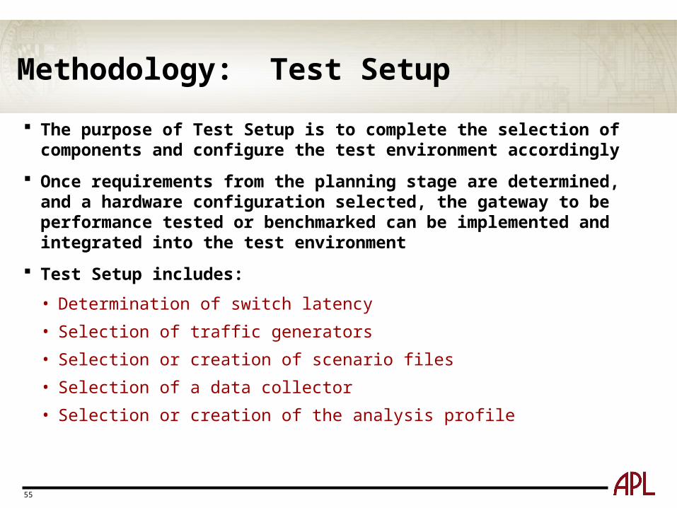
Methodology: Test Setup
The purpose of Test Setup is to complete the selection of components and configure the test environment accordingly
Once requirements from the planning stage are determined, and a hardware configuration selected, the gateway to be performance tested or benchmarked can be implemented and integrated into the test environment
Test Setup includes:
• Determination of switch latency
• Selection of traffic generators
• Selection or creation of scenario files
• Selection of a data collector
• Selection or creation of the analysis profile
56
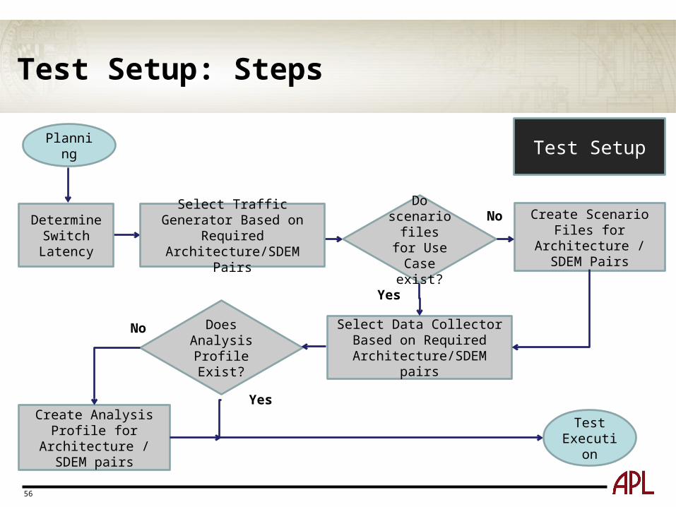
Test Setup: Steps
Test SetupPlanning
Determine Switch
Latency
Create Scenario Files for Architecture /
SDEM Pairs
Select Data Collector Based on Required
Architecture/SDEM pairs
Does Analysis Profile Exist?
No
Yes
Create Analysis Profile for Architecture /
SDEM pairs
No
Yes
Test Execution
Select Traffic Generator Based on Required
Architecture/SDEM Pairs
Do scenario
files for Use Case exist?
57
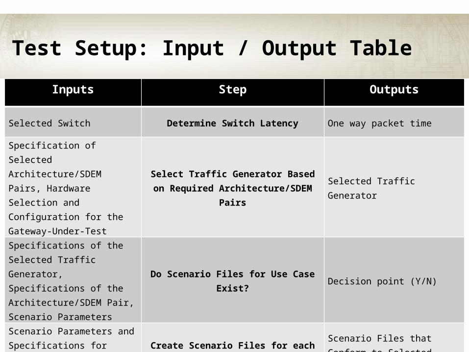
Test Setup: Input / Output Table
Inputs Step Outputs
Selected Switch Determine Switch Latency One way packet time
Specification of Selected Architecture/SDEM Pairs, Hardware Selection and Configuration for the Gateway-Under-Test
Select Traffic Generator Based on Required Architecture/SDEM Pairs
Selected Traffic Generator
Specifications of the Selected Traffic Generator, Specifications of the Architecture/SDEM Pair, Scenario Parameters
Do Scenario Files for Use Case Exist? Decision point (Y/N)
Scenario Parameters and Specifications for Selected Architecture/SDEM Pairs
Create Scenario Files for each Architecture/SDEM Pair
Scenario Files that Conform to Selected Traffic Generator(s)
58
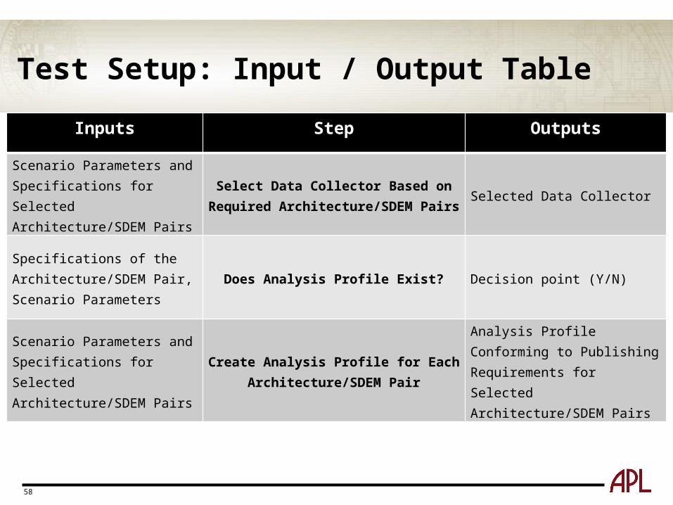
Test Setup: Input / Output Table
Inputs Step Outputs
Scenario Parameters and Specifications for Selected Architecture/SDEM Pairs
Select Data Collector Based on Required Architecture/SDEM Pairs
Selected Data Collector
Specifications of the Architecture/SDEM Pair, Scenario Parameters
Does Analysis Profile Exist? Decision point (Y/N)
Scenario Parameters and Specifications for Selected Architecture/SDEM Pairs
Create Analysis Profile for Each Architecture/SDEM Pair
Analysis Profile Conforming to Publishing Requirements for Selected Architecture/SDEM Pairs
59
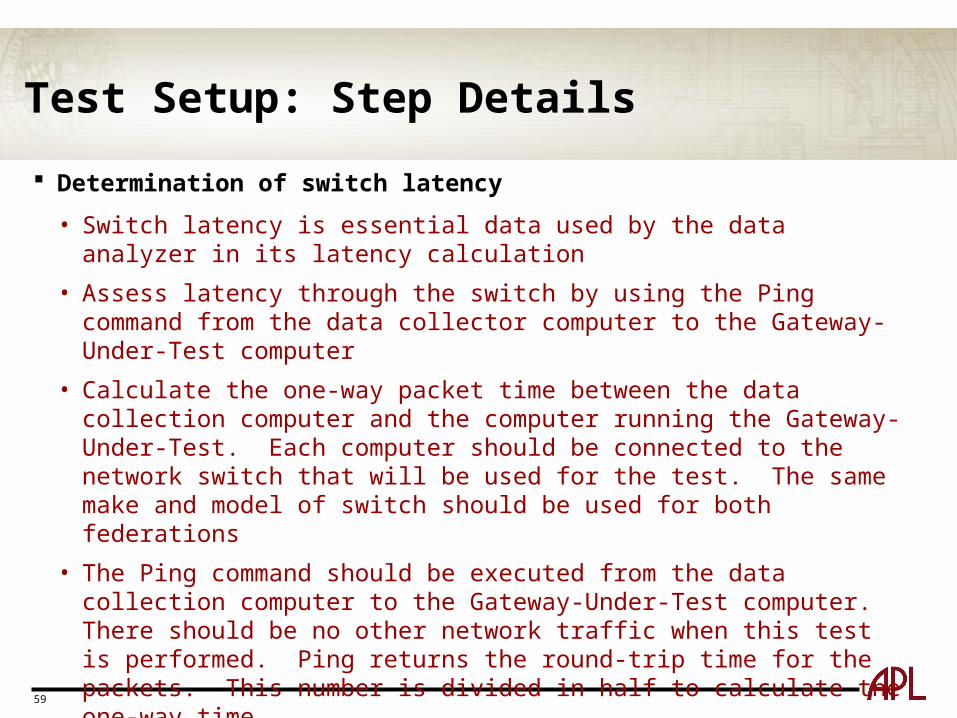
Test Setup: Step Details
Determination of switch latency
• Switch latency is essential data used by the data analyzer in its latency calculation
• Assess latency through the switch by using the Ping command from the data collector computer to the Gateway-Under-Test computer
• Calculate the one-way packet time between the data collection computer and the computer running the Gateway-Under-Test. Each computer should be connected to the network switch that will be used for the test. The same make and model of switch should be used for both federations
• The Ping command should be executed from the data collection computer to the Gateway-Under-Test computer. There should be no other network traffic when this test is performed. Ping returns the round-trip time for the packets. This number is divided in half to calculate the one-way time
• Most large distributed simulations will be run on enterprise-grade switches. It is recommended that enterprise-grade switches be used
60
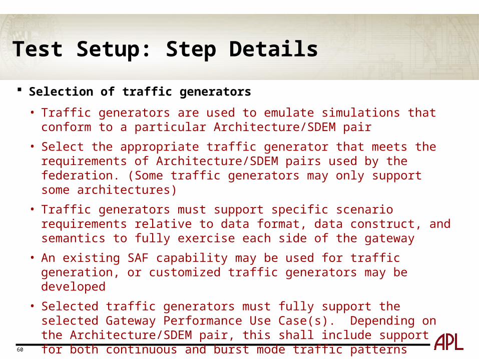
Test Setup: Step Details
Selection of traffic generators
• Traffic generators are used to emulate simulations that conform to a particular Architecture/SDEM pair
• Select the appropriate traffic generator that meets the requirements of Architecture/SDEM pairs used by the federation. (Some traffic generators may only support some architectures)
• Traffic generators must support specific scenario requirements relative to data format, data construct, and semantics to fully exercise each side of the gateway
• An existing SAF capability may be used for traffic generation, or customized traffic generators may be developed
• Selected traffic generators must fully support the selected Gateway Performance Use Case(s). Depending on the Architecture/SDEM pair, this shall include support for both continuous and burst mode traffic patterns
61
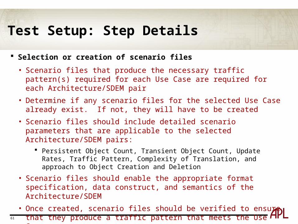
Test Setup: Step Details
Selection or creation of scenario files
• Scenario files that produce the necessary traffic pattern(s) required for each Use Case are required for each Architecture/SDEM pair
• Determine if any scenario files for the selected Use Case already exist. If not, they will have to be created
• Scenario files should include detailed scenario parameters that are applicable to the selected Architecture/SDEM pairs:
Persistent Object Count, Transient Object Count, Update Rates, Traffic Pattern, Complexity of Translation, and approach to Object Creation and Deletion
• Scenario files should enable the appropriate format specification, data construct, and semantics of the Architecture/SDEM
• Once created, scenario files should be verified to ensure that they produce a traffic pattern that meets the Use Case
• Verified scenario files should be archived in a designated repository that supports version control, accessible to the appropriate user communities
62
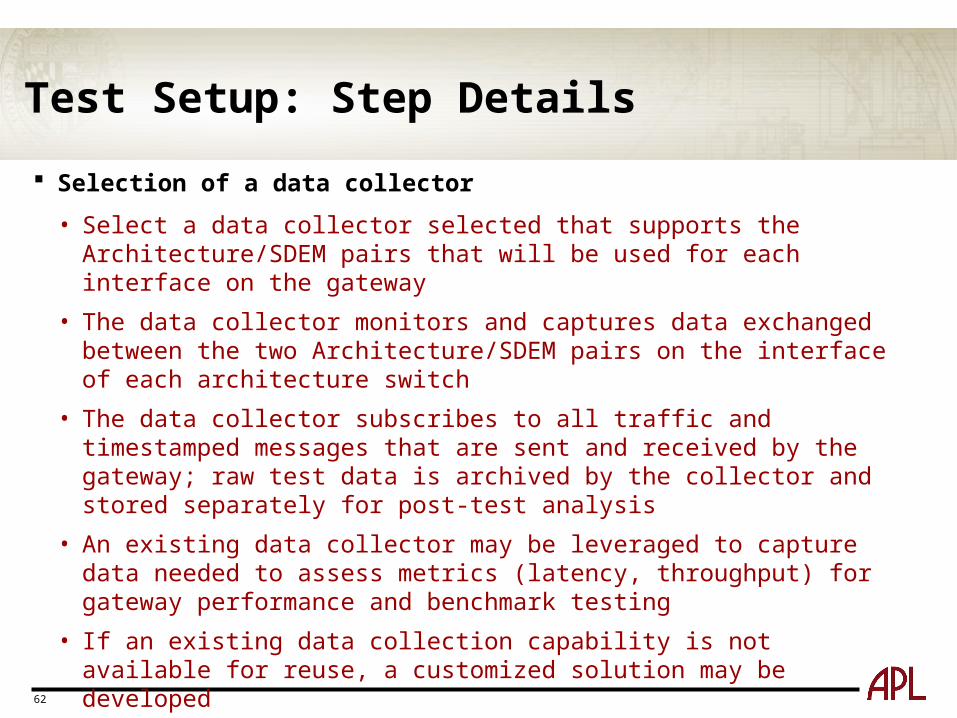
Test Setup: Step Details
Selection of a data collector
• Select a data collector selected that supports the Architecture/SDEM pairs that will be used for each interface on the gateway
• The data collector monitors and captures data exchanged between the two Architecture/SDEM pairs on the interface of each architecture switch
• The data collector subscribes to all traffic and timestamped messages that are sent and received by the gateway; raw test data is archived by the collector and stored separately for post-test analysis
• An existing data collector may be leveraged to capture data needed to assess metrics (latency, throughput) for gateway performance and benchmark testing
• If an existing data collection capability is not available for reuse, a customized solution may be developed
• The selected data collector should be similar to, or match, the standard data collection instrumentation as may be used during a distributed simulation to monitor gateway traffic
63
Test Setup: Step Details
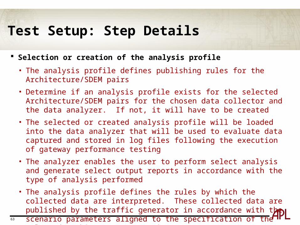
Selection or creation of the analysis profile
• The analysis profile defines publishing rules for the Architecture/SDEM pairs
• Determine if an analysis profile exists for the selected Architecture/SDEM pairs for the chosen data collector and the data analyzer. If not, it will have to be created
• The selected or created analysis profile will be loaded into the data analyzer that will be used to evaluate data captured and stored in log files following the execution of gateway performance testing
• The analyzer enables the user to perform select analysis and generate select output reports in accordance with the type of analysis performed
• The analysis profile defines the rules by which the collected data are interpreted. These collected data are published by the traffic generator in accordance with the scenario parameters aligned to the specification of the selected Architecture/SDEM pairs
64
Methodology: Test Execution
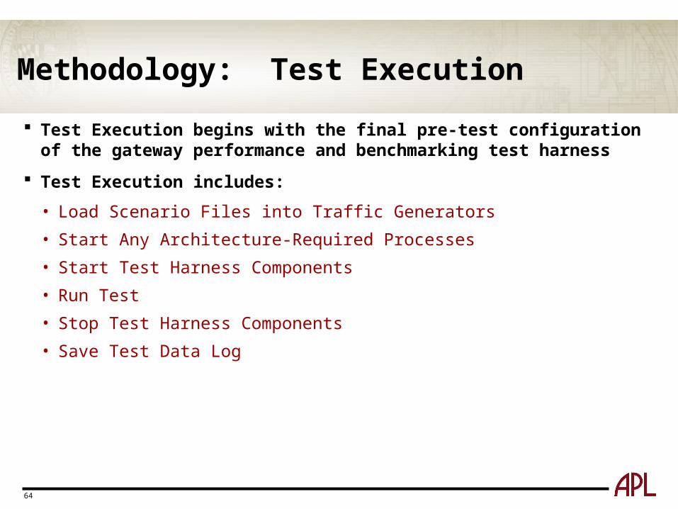
Test Execution begins with the final pre-test configuration of the gateway performance and benchmarking test harness
Test Execution includes:
• Load Scenario Files into Traffic Generators
• Start Any Architecture-Required Processes
• Start Test Harness Components
• Run Test
• Stop Test Harness Components
• Save Test Data Log
65
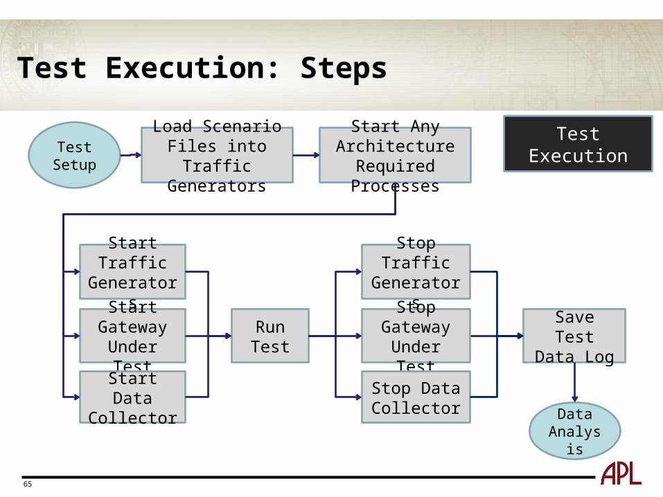
Test Execution: Steps
Test Setup
Data Analysis
Load Scenario Files into Traffic Generators
Start Any Architecture Required Processes
Start Traffic Generators
Start Gateway Under Test
Start Data Collector
Run Test
Stop Traffic Generators
Stop Gateway Under Test
Stop Data Collector
Save Test Data Log
Test Execution
66
Test Execution: Input / Output Table
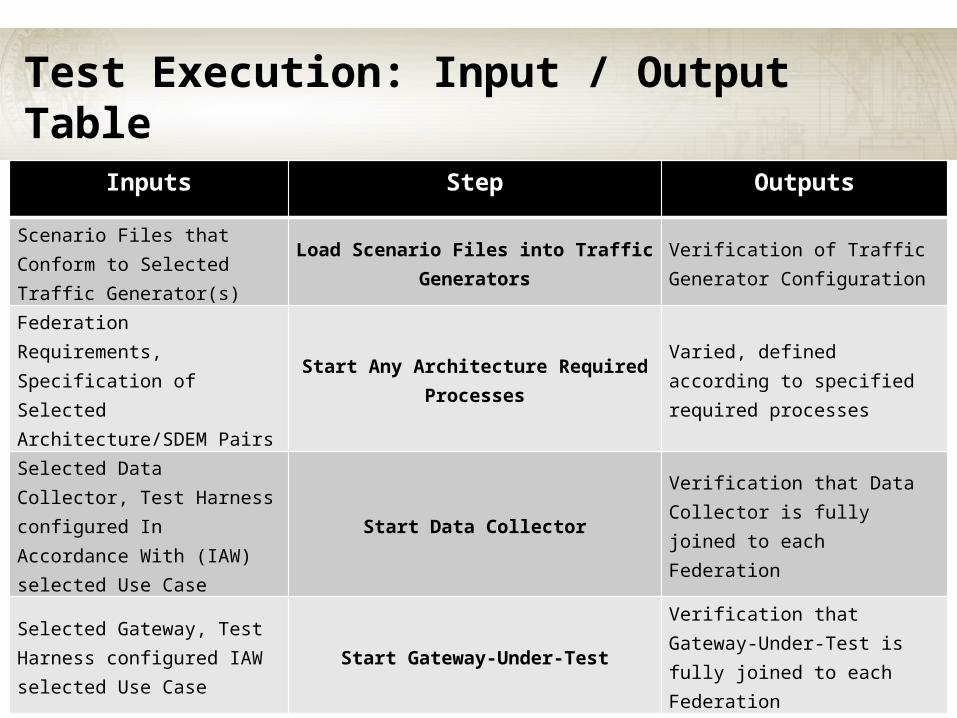
Inputs Step Outputs
Scenario Files that Conform to Selected Traffic Generator(s)
Load Scenario Files into Traffic Generators
Verification of Traffic Generator Configuration
Federation Requirements, Specification of Selected Architecture/SDEM Pairs
Start Any Architecture Required Processes
Varied, defined according to specified required processes
Selected Data Collector, Test Harness configured In Accordance With (IAW) selected Use Case
Start Data CollectorVerification that Data Collector is fully joined to each Federation
Selected Gateway, Test Harness configured IAW selected Use Case
Start Gateway-Under-TestVerification that Gateway-Under-Test is fully joined to each Federation
67
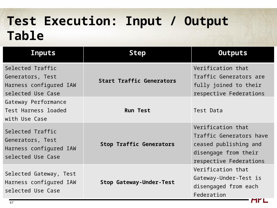
Test Execution: Input / Output Table
Inputs Step Outputs
Selected Traffic Generators, Test Harness configured IAW selected Use Case
Start Traffic GeneratorsVerification that Traffic Generators are fully joined to their respective Federations
Gateway Performance Test Harness loaded with Use Case
Run Test Test Data
Selected Traffic Generators, Test Harness configured IAW selected Use Case
Stop Traffic Generators
Verification that Traffic Generators have ceased publishing and disengage from their respective Federations
Selected Gateway, Test Harness configured IAW selected Use Case
Stop Gateway-Under-TestVerification that Gateway-Under-Test is disengaged from each Federation

68
Test Execution: Input / Output Table
Inputs Step Outputs
Selected Data Collector, Test Harness configured IAW selected Use Case
Stop Data Collector
Verification that Data Collector ceases collection operation and is disengaged from each Federation
Selected Data Collector, Test Harness configured IAW selected Use Case
Save Test Data Log Saved Test Data Logs
69
Test Execution: Step Details
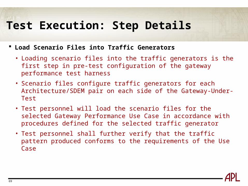
Load Scenario Files into Traffic Generators
• Loading scenario files into the traffic generators is the first step in pre-test configuration of the gateway performance test harness
• Scenario files configure traffic generators for each Architecture/SDEM pair on each side of the Gateway-Under-Test
• Test personnel will load the scenario files for the selected Gateway Performance Use Case in accordance with procedures defined for the selected traffic generator
• Test personnel shall further verify that the traffic pattern produced conforms to the requirements of the Use Case
70
Test Execution: Step Details
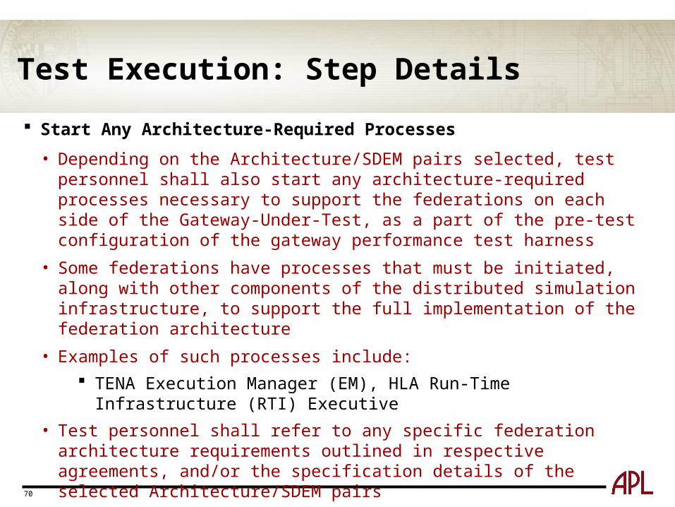
Start Any Architecture-Required Processes
• Depending on the Architecture/SDEM pairs selected, test personnel shall also start any architecture-required processes necessary to support the federations on each side of the Gateway-Under-Test, as a part of the pre-test configuration of the gateway performance test harness
• Some federations have processes that must be initiated, along with other components of the distributed simulation infrastructure, to support the full implementation of the federation architecture
• Examples of such processes include:
TENA Execution Manager (EM), HLA Run-Time Infrastructure (RTI) Executive
• Test personnel shall refer to any specific federation architecture requirements outlined in respective agreements, and/or the specification details of the selected Architecture/SDEM pairs
71
Test Execution: Step Details
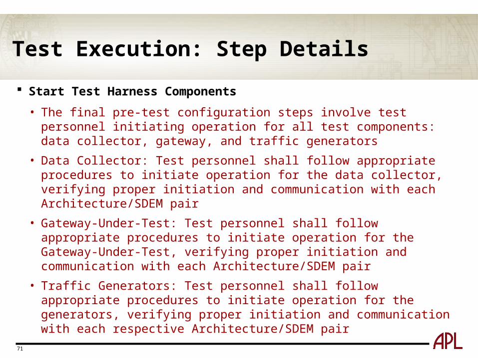
Start Test Harness Components
• The final pre-test configuration steps involve test personnel initiating operation for all test components: data collector, gateway, and traffic generators
• Data Collector: Test personnel shall follow appropriate procedures to initiate operation for the data collector, verifying proper initiation and communication with each Architecture/SDEM pair
• Gateway-Under-Test: Test personnel shall follow appropriate procedures to initiate operation for the Gateway-Under-Test, verifying proper initiation and communication with each Architecture/SDEM pair
• Traffic Generators: Test personnel shall follow appropriate procedures to initiate operation for the generators, verifying proper initiation and communication with each respective Architecture/SDEM pair
72
Test Execution: Step Details
Run Test
• Test personnel shall initiate publishing of data via the traffic generators on each side of the Gateway-Under-Test, in accordance with the prescribed Gateway Performance Use Case
• Personnel shall monitor and verify operation as warranted by the Use Case, to include data publication via the traffic generators, other federation processes as required, and data collection
• The test continues until completion of all planned activities or planned test duration
73
Test Execution: Step Details
Stop Test Harness Components
• At the conclusion of the test, personnel shall stop operation of all test components: traffic generators, Gateway-Under-Test, and data collector
• Traffic Generators: Test personnel shall follow appropriate procedures to initiate shutdown, ensuring that data publishing ceases and that the generators disengage from each respective Architecture/SDEM pair
• Gateway-Under-Test: Test personnel shall follow appropriate procedures to initiate shutdown, ensuring that the gateway properly disengages from each Architecture/SDEM pair
• Data Collector: Test personnel shall follow appropriate procedures to initiate shutdown, ensuring that the collector properly disengages from each Architecture/SDEM pair
74
Test Execution: Step Details
Save Test Data Log
• Following the completion of all test component shutdown procedures, test personnel shall ensure the proper archival and storage of collected test data
• Raw test data captured by the data collector shall be stored to a designated repository in the form of data logs that can be later be loaded into the data analyzer
75
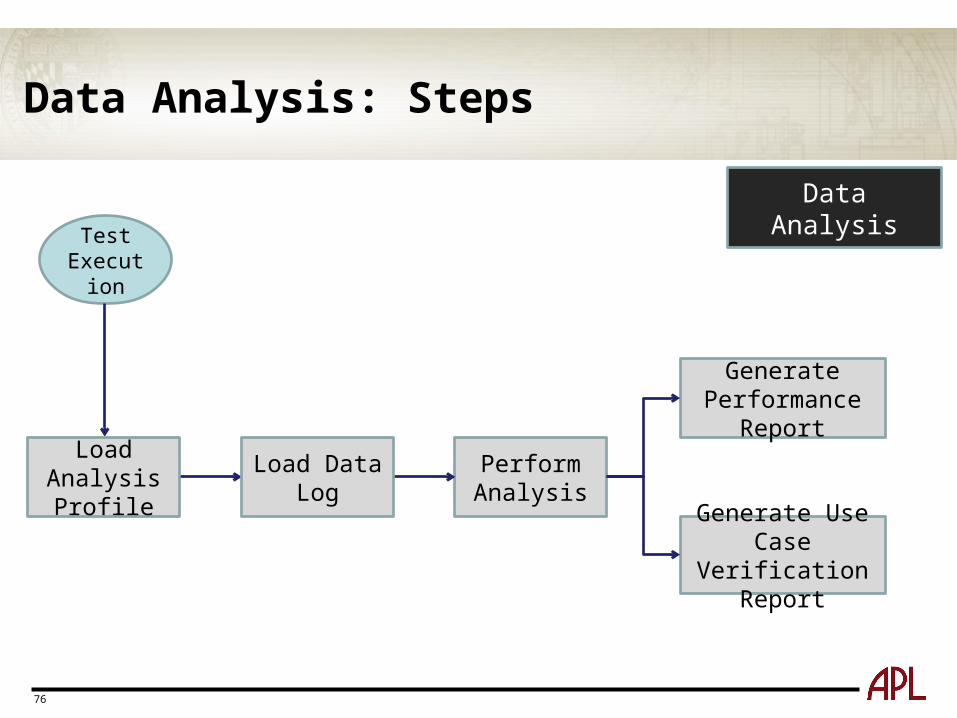
Methodology: Data Analysis
Data Analysis takes as input the analysis profile produced or acquired during Test Setup and the saved test data logs from the Test Execution stage
The data analyzer is used to calculate performance metrics and generate the necessary performance and benchmarking reports
Data Analysis includes:
• Load Analysis Profile into Data Analyzer
• Load Test Data Logs into Data Analyzer
• Perform Analysis
• Generate Performance Report
• Generate Use Case Verification Report
76
Data Analysis: Steps
Test Execution
Generate Performance Report
Generate Use Case Verification Report
Perform Analysis
Load Analysis Profile Load Data Log
Data Analysis
77
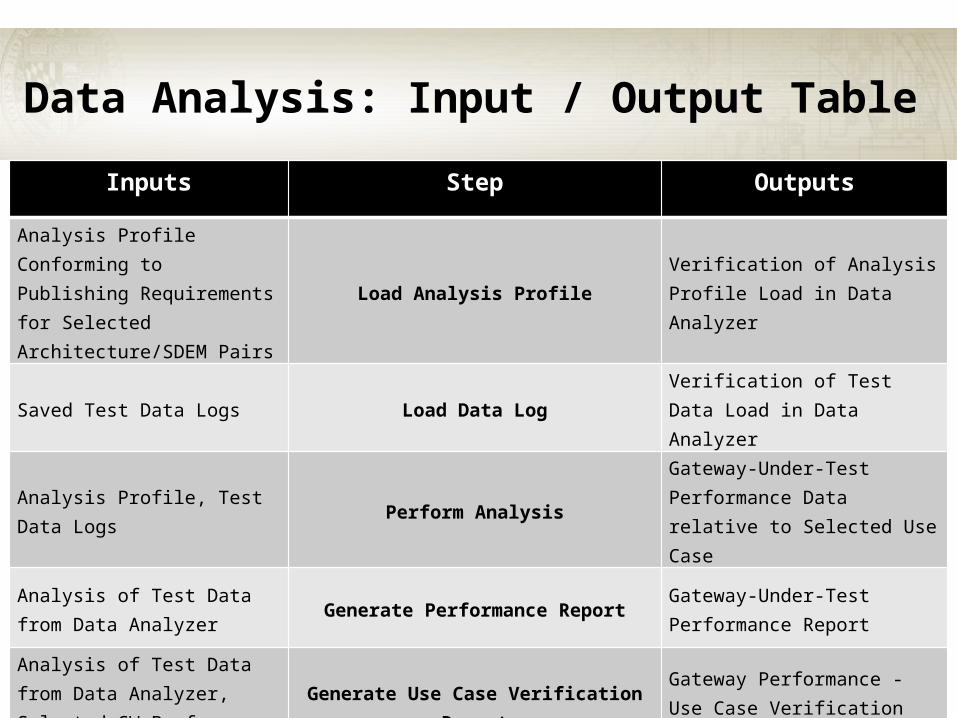
Data Analysis: Input / Output Table
Inputs Step Outputs
Analysis Profile Conforming to Publishing Requirements for Selected Architecture/SDEM Pairs
Load Analysis ProfileVerification of Analysis Profile Load in Data Analyzer
Saved Test Data Logs Load Data LogVerification of Test Data Load in Data Analyzer
Analysis Profile, Test Data Logs Perform AnalysisGateway-Under-Test Performance Data relative to Selected Use Case
Analysis of Test Data from Data Analyzer
Generate Performance ReportGateway-Under-Test Performance Report
Analysis of Test Data from Data Analyzer, Selected GW Performance Use Case(s)
Generate Use Case Verification ReportGateway Performance - Use Case Verification Report
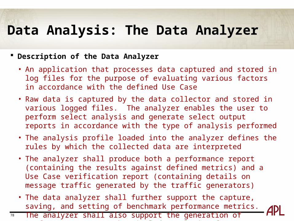
Data Analysis: The Data Analyzer
Description of the Data Analyzer
• An application that processes data captured and stored in log files for the purpose of evaluating various factors in accordance with the defined Use Case
• Raw data is captured by the data collector and stored in various logged files. The analyzer enables the user to perform select analysis and generate select output reports in accordance with the type of analysis performed
• The analysis profile loaded into the analyzer defines the rules by which the collected data are interpreted
• The analyzer shall produce both a performance report (containing the results against defined metrics) and a Use Case verification report (containing details on message traffic generated by the traffic generators)
• The data analyzer shall further support the capture, saving, and setting of benchmark performance metrics. The analyzer shall also support the generation of performance reports that include analysis of gateway performance against one or more selected benchmarks
78
79
Data Analysis: Step Details
Load Analysis Profile into Data Analyzer
• Following appropriate procedures, analysts shall load the analysis profile into the data analyzer to evaluate data captured and stored in log files following the execution of gateway performance testing
• The analysis profile must conform to the publishing requirements of the federations utilized for the selected Gateway Performance Use Case(s)
80
Data Analysis: Step Details
Load Test Data Logs into Data Analyzer
• Test data logs are loaded into the data analyzer, following appropriate procedures
• Test data logs, coupled with the selected analysis profile, allow analysts to evaluate the data in accordance with the Gateway Performance Use Case
Perform Analysis
• The data analyzer allows the analyst user to perform select analyses to assess the performance of the Gateway-Under-Test against defined measures or otherwise specified performance metrics or benchmarks
• Using the pre-loaded analysis profile and test data logs (and any other pre-loaded benchmark or performance threshold configuration parameters), the analyst shall initiate the analysis activity using the data analyzer
81
Data Analysis: Step Details
Generate Performance Report
• Following analysis, analysts will use the data analyzer to generate a Gateway-Under-Test Performance Report
• The Gateway-Under-Test Performance Report includes detailed results using the eight predefined metrics for latency and throughput on persistent and transient objects
• The report may also contain information describing the scenario parameters and operational parameters that serve to characterize the Use Case and place performance results into context
82
Data Analysis: Step Details
Generate Use Case Verification Report
• Following analysis, analysts will use the data analyzer to generate a Use Case Verification Report
• The Use Case Verification Report is used to verify the proper operation of the gateway performance and benchmarking test harness
• This report shall overlay Gateway-Under-Test performance captured by the data collector against the actual recorded network traffic through the gateway interfaces as published by the traffic generators
• In addition to verifying the proper publication of the defined Use Case traffic pattern for the test, the report shall support additional detailed analysis of the Gateway-Under-Test in the context of the selected performance Use Case
83
Introductory Session:Summary and Feedback Breakout into Developer and User groups
Each group will review the same issues focused on the specific needs of developers and users
Each group will produce a summary slide
We will have a short combined session after the breakouts
Please turn in workshop questionnaire before breakouts
84
Breakout Session:Developer Group Introductions
Purpose: To collect feedback from the perspective of the gateway developers
Approach: Review the 4 aspects of the Performance Benchmarks and obtain feedback
Products: Notes from Discussions for use in enhancing Performance Benchmarks, Summary of Discussion for Plenary
85
Developers: Performance Use Cases
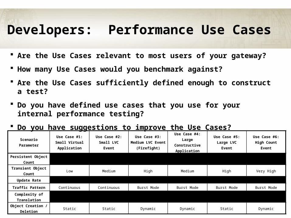
Are the Use Cases relevant to most users of your gateway?
How many Use Cases would you benchmark against?
Are the Use Cases sufficiently defined enough to construct a test?
Do you have defined use cases that you use for your internal performance testing?
Do you have suggestions to improve the Use Cases?
Scenario ParameterUse Case #1:Small Virtual Application
Use Case #2:Small LVC
Event
Use Case #3:Medium LVC Event
(Firefight)
Use Case #4:Large Constructive
Application
Use Case #5:Large LVC
Event
Use Case #6:High Count
Event
Persistent Object Count
Low Medium Medium High High Very High
Transient Object Count
Low Medium High Medium High Very High
Update Rate High Very High Medium Low Medium Medium
Traffic Pattern Continuous Continuous Burst Mode Burst Mode Burst Mode Burst Mode
Complexity of Translation
Low Medium Medium High High Medium
Object Creation /Deletion
Static Static Dynamic Dynamic Static Dynamic
86
Developers: Metrics
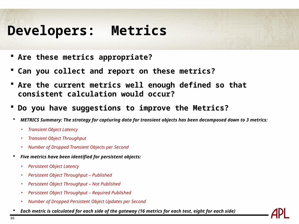
Are these metrics appropriate?
Can you collect and report on these metrics?
Are the current metrics well enough defined so that consistent calculation would occur?
Do you have suggestions to improve the Metrics? METRICS Summary: The strategy for capturing data for transient objects has been decomposed down to 3 metrics:
• Transient Object Latency
• Transient Object Throughput
• Number of Dropped Transient Objects per Second
Five metrics have been identified for persistent objects:
• Persistent Object Latency
• Persistent Object Throughput – Published
• Persistent Object Throughput – Not Published
• Persistent Object Throughput – Required Published
• Number of Dropped Persistent Object Updates per Second
Each metric is calculated for each side of the gateway (16 metrics for each test, eight for each side)
87
Developers: Test Harness
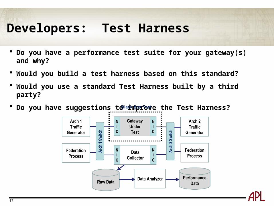
Do you have a performance test suite for your gateway(s) and why?
Would you build a test harness based on this standard?
Would you use a standard Test Harness built by a third party?
Do you have suggestions to improve the Test Harness?
88
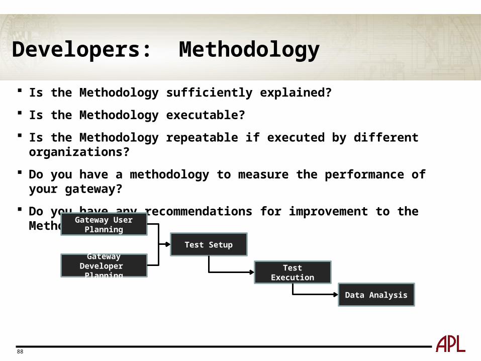
Developers: Methodology
Is the Methodology sufficiently explained?
Is the Methodology executable?
Is the Methodology repeatable if executed by different organizations?
Do you have a methodology to measure the performance of your gateway?
Do you have any recommendations for improvement to the Methodology
Gateway User Planning
Gateway Developer Planning
Test Setup
Test Execution
Data Analysis
89
Developers: General Questions
Do you see value in standardizing performance standards/tools?
Are your customers asking for performance numbers?
• If yes, how to you determine and provide this information?
• If yes, what performance numbers are they requesting?
What's important to them?
Do you have suggestions to improve the proposed benchmark?

90
Breakout Session:Users Group Introductions
Purpose: To collect feedback from the perspective of the gateway Users
Approach: Review the 4 aspects of the Performance Benchmarks and obtain feedback
Products: Notes from Discussions for use in enhancing Performance Benchmarks, Summary of Discussion for Plenary
91
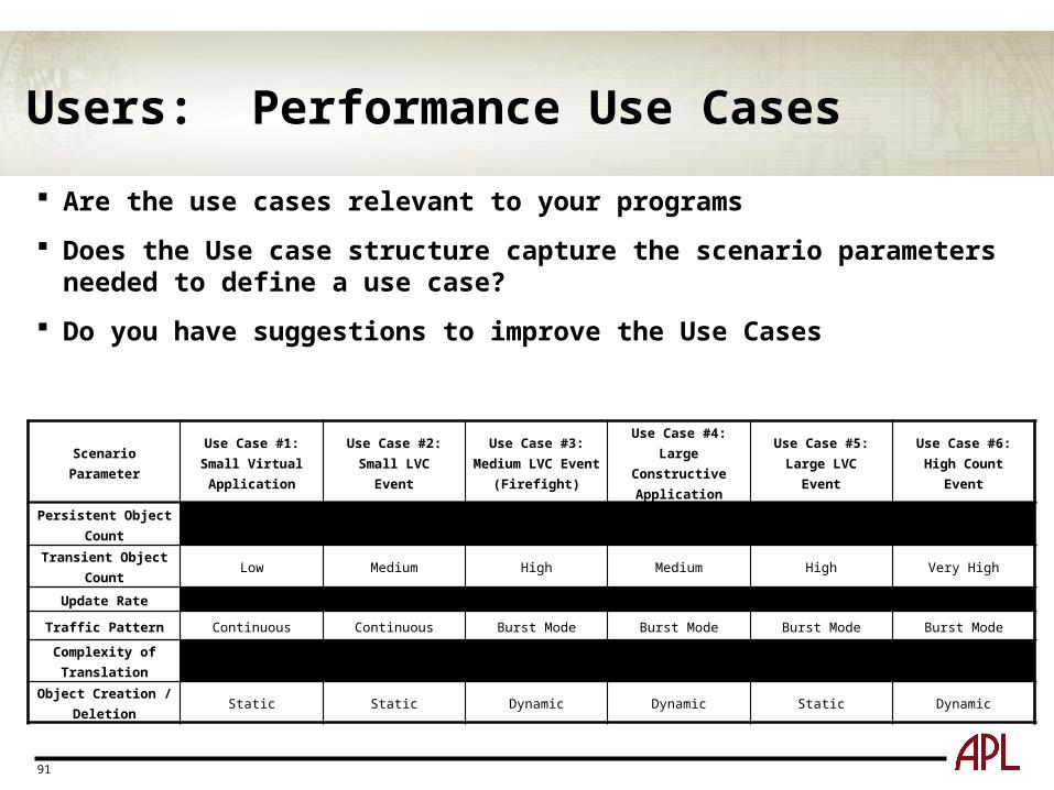
Users: Performance Use Cases
Are the use cases relevant to your programs
Does the Use case structure capture the scenario parameters needed to define a use case?
Do you have suggestions to improve the Use Cases
Scenario ParameterUse Case #1:Small Virtual Application
Use Case #2:Small LVC
Event
Use Case #3:Medium LVC Event
(Firefight)
Use Case #4:Large Constructive
Application
Use Case #5:Large LVC
Event
Use Case #6:High Count
Event
Persistent Object Count
Low Medium Medium High High Very High
Transient Object Count
Low Medium High Medium High Very High
Update Rate High Very High Medium Low Medium Medium
Traffic Pattern Continuous Continuous Burst Mode Burst Mode Burst Mode Burst Mode
Complexity of Translation
Low Medium Medium High High Medium
Object Creation /Deletion
Static Static Dynamic Dynamic Static Dynamic
92
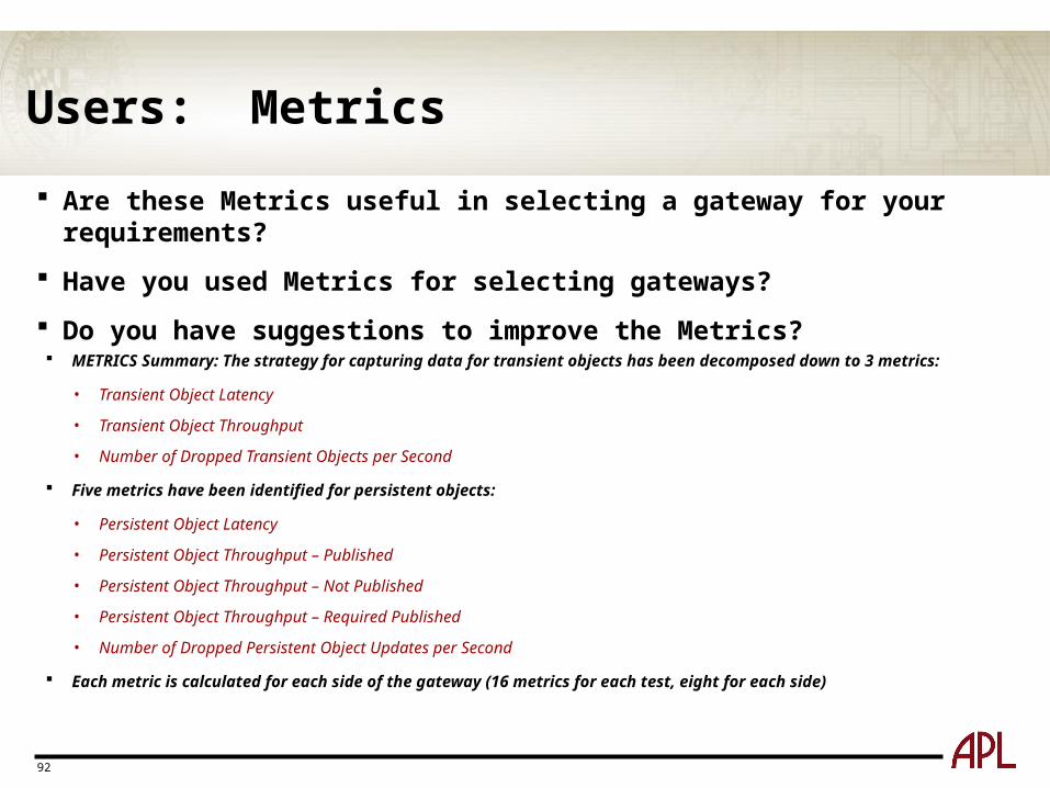
Users: Metrics
Are these Metrics useful in selecting a gateway for your requirements?
Have you used Metrics for selecting gateways?
Do you have suggestions to improve the Metrics?
METRICS Summary: The strategy for capturing data for transient objects has been decomposed down to 3 metrics:
• Transient Object Latency
• Transient Object Throughput
• Number of Dropped Transient Objects per Second
Five metrics have been identified for persistent objects:
• Persistent Object Latency
• Persistent Object Throughput – Published
• Persistent Object Throughput – Not Published
• Persistent Object Throughput – Required Published
• Number of Dropped Persistent Object Updates per Second
Each metric is calculated for each side of the gateway (16 metrics for each test, eight for each side)
93
Users: Test Harness
Have you built an environment to test the performance of gateways to support gateway selection?
Would you build a tool that meets a standard?
Would you use a gateway performance tool (test harness)?
Do you have suggestions to improve the Test Harness?
94
Users: Methodology
When selecting a gateway, have you used a defined methodology to measure its performance?
Would you use a standard methodology to measure the performance of a gateway?
Do you have suggestions to improve the Methodology?
Gateway User Planning
Gateway Developer Planning
Test Setup
Test Execution
Data Analysis

95
User: General Questions
Do you see value in standardizing performance standards/tools?
Are your customers asking for performance numbers?
• If yes, how to you determine and provide this information?
• If yes, what performance numbers are they requesting?
What's important to them?
Do you have suggestions to improve the proposed benchmark?
Performance Benchmark Workshop Summary Thank you for your participation
Please return the workshop Homework materials
• Material and Instructions will be provided via email
Information gathered in this workshop will drive improvements to the Gateway Performance Benchmark
• Will be the focus of the second Workshop tentatively planned for August 2013
96
References
97
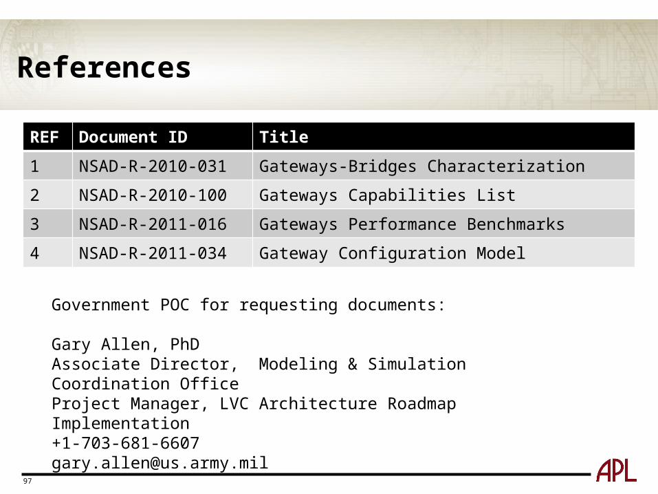
REF Document ID Title
1 NSAD-R-2010-031 Gateways-Bridges Characterization
2 NSAD-R-2010-100 Gateways Capabilities List
3 NSAD-R-2011-016 Gateways Performance Benchmarks
4 NSAD-R-2011-034 Gateway Configuration Model
Government POC for requesting documents:
Gary Allen, PhDAssociate Director, Modeling & Simulation Coordination OfficeProject Manager, LVC Architecture Roadmap [email protected]
Acronyms
98
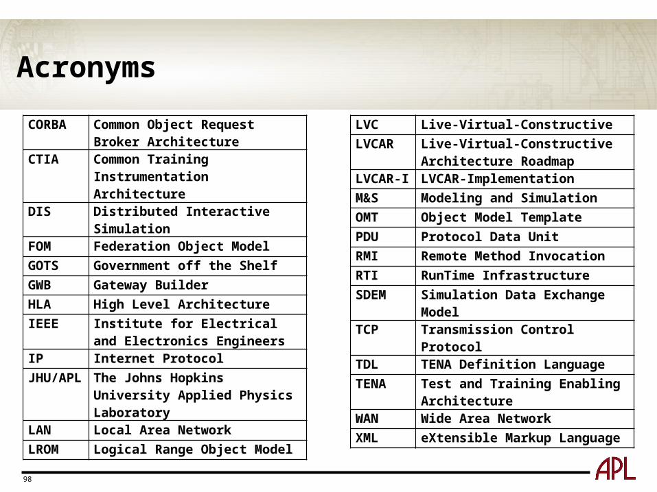
CORBA Common Object Request Broker Architecture
CTIA Common Training Instrumentation Architecture
DIS Distributed Interactive Simulation FOM Federation Object ModelGOTS Government off the ShelfGWB Gateway BuilderHLA High Level ArchitectureIEEE Institute for Electrical and Electronics
EngineersIP Internet ProtocolJHU/APL The Johns Hopkins University Applied
Physics LaboratoryLAN Local Area NetworkLROM Logical Range Object Model
LVC Live-Virtual-ConstructiveLVCAR Live-Virtual-Constructive Architecture
RoadmapLVCAR-I LVCAR-ImplementationM&S Modeling and SimulationOMT Object Model TemplatePDU Protocol Data UnitRMI Remote Method InvocationRTI RunTime InfrastructureSDEM Simulation Data Exchange ModelTCP Transmission Control ProtocolTDL TENA Definition Language TENA Test and Training Enabling ArchitectureWAN Wide Area NetworkXML eXtensible Markup Language

99